KR101491076B1 - Exploreration robot - Google Patents
Exploreration robotDownload PDFInfo
- Publication number
- KR101491076B1 KR101491076B1KR20140019429AKR20140019429AKR101491076B1KR 101491076 B1KR101491076 B1KR 101491076B1KR 20140019429 AKR20140019429 AKR 20140019429AKR 20140019429 AKR20140019429 AKR 20140019429AKR 101491076 B1KR101491076 B1KR 101491076B1
- Authority
- KR
- South Korea
- Prior art keywords
- robot
- lifting
- piston rod
- traveling
- flying
- Prior art date
- Legal status (The legal status is an assumption and is not a legal conclusion. Google has not performed a legal analysis and makes no representation as to the accuracy of the status listed.)
- Active
Links
Images


Classifications
- B—PERFORMING OPERATIONS; TRANSPORTING
- B25—HAND TOOLS; PORTABLE POWER-DRIVEN TOOLS; MANIPULATORS
- B25J—MANIPULATORS; CHAMBERS PROVIDED WITH MANIPULATION DEVICES
- B25J19/00—Accessories fitted to manipulators, e.g. for monitoring, for viewing; Safety devices combined with or specially adapted for use in connection with manipulators
- B25J19/02—Sensing devices
- B—PERFORMING OPERATIONS; TRANSPORTING
- B25—HAND TOOLS; PORTABLE POWER-DRIVEN TOOLS; MANIPULATORS
- B25J—MANIPULATORS; CHAMBERS PROVIDED WITH MANIPULATION DEVICES
- B25J5/00—Manipulators mounted on wheels or on carriages
- B25J5/007—Manipulators mounted on wheels or on carriages mounted on wheels
- B—PERFORMING OPERATIONS; TRANSPORTING
- B25—HAND TOOLS; PORTABLE POWER-DRIVEN TOOLS; MANIPULATORS
- B25J—MANIPULATORS; CHAMBERS PROVIDED WITH MANIPULATION DEVICES
- B25J9/00—Programme-controlled manipulators
- B25J9/16—Programme controls
- B25J9/1674—Programme controls characterised by safety, monitoring, diagnostic
- B—PERFORMING OPERATIONS; TRANSPORTING
- B64—AIRCRAFT; AVIATION; COSMONAUTICS
- B64C—AEROPLANES; HELICOPTERS
- B64C39/00—Aircraft not otherwise provided for
- B64C39/02—Aircraft not otherwise provided for characterised by special use
- B64C39/028—Micro-sized aircraft
- Y—GENERAL TAGGING OF NEW TECHNOLOGICAL DEVELOPMENTS; GENERAL TAGGING OF CROSS-SECTIONAL TECHNOLOGIES SPANNING OVER SEVERAL SECTIONS OF THE IPC; TECHNICAL SUBJECTS COVERED BY FORMER USPC CROSS-REFERENCE ART COLLECTIONS [XRACs] AND DIGESTS
- Y10—TECHNICAL SUBJECTS COVERED BY FORMER USPC
- Y10S—TECHNICAL SUBJECTS COVERED BY FORMER USPC CROSS-REFERENCE ART COLLECTIONS [XRACs] AND DIGESTS
- Y10S901/00—Robots
- Y10S901/01—Mobile robot
Landscapes
- Engineering & Computer Science (AREA)
- Robotics (AREA)
- Mechanical Engineering (AREA)
- Aviation & Aerospace Engineering (AREA)
- Manipulator (AREA)
Abstract
Translated fromKoreanDescription
Translated fromKorean본 발명은 주행로봇과 비행로봇으로 이루어진 탐사용 로봇에 관한 것이다.
The present invention relates to a navigation robot comprising a traveling robot and a flying robot.
감시 및 정찰과 같은 군사 분야에서처럼 인간의 접근과 개입이 어렵거나 불가능한 거친 외부 환경에서 운용되는 무인장치들이 개발되어 사용되고 있다.Unmanned devices that operate in rough external environments where human access and intervention are difficult or impossible, such as in the military field, such as surveillance and reconnaissance, are being developed and used.
전술한 무인장치로는 무인 지상차량(UGV)과 무인 비행체(UAV)를 들 수 있으며, 무인 비행체는 고정익형 무인 비행체와 회전익형 무인 비행체로 나눌 수 있다.Unmanned vehicles (UGV) and unmanned aerial vehicles (UAV) can be cited as the above-mentioned unmanned vehicles. Unmanned vehicles can be classified into fixed-wing unmanned aerial vehicles and wing-wing unmanned aerial vehicles.
그런데, 전술한 무인 지상차량은 원거리를 이동할 때 기동성이 떨어지는 문제점이 있었으며, 무인 비행체는 지상구동이 필요할 때 활용도가 떨어지는 문제점이 있었다.However, the above-mentioned unmanned ground vehicle has a problem in that the maneuverability is low when moving over a long distance, and the unmanned aerial vehicle has a problem in that the utilization of the unmanned aerial vehicle is inferior when the ground driving is needed.
한편, 전술한 문제점을 해결하기 위해서 "대한민국공개특허 제 2013-0005501 호"에는 무인 지상차량의 정찰 임무와 무인 비행체의 정찰 임무를 동시에 수행할 수 있도록 무인 지상차량과 무인 비행체를 통합한 무인 정찰 로봇이 개시되어 있다.In order to solve the above-mentioned problem, Korean Patent Laid-Open Publication No. 2013-0005501 discloses an unmanned reconnaissance robot incorporating an unmanned ground vehicle and an unmanned aerial vehicle so that the reconnaissance mission of the unmanned ground vehicle and the reconnaissance mission of the unmanned air vehicle can be performed simultaneously. .
그러나 "대한민국공개특허 제 2013-0005501 호"에 개시된 무인 정찰 로봇은 무인 지상차량 또는 무인 비행체가 가지는 공간 이동의 제한성을 극복할 수 있는 이점은 있으나, 하나의 장치에 무인 지상차량의 특징과 무인 비행체의 특징이 통합되어 있기 때문에 지상 탐사(정찰)임무와 비행 탐사임무를 동시에 수행하지 못하는 문제점이 있었다.However, the unmanned reconnaissance robot disclosed in "Korean Patent Laid-Open Publication No. 2013-0005501" has an advantage that it can overcome limitations of space movement of unmanned ground vehicles or unmanned aerial vehicles, (Reconnaissance) missions and flight exploration missions can not be performed at the same time.
따라서 무인 지상차량과 무인 비행체가 별도로 구비되면서 필요 시 연결 및 분리될 수 있는 탐사용 로봇의 개발이 요구되고 있는 실정이다.
Therefore, it is required to develop a navigation robot that can be connected and disconnected when necessary, as the unmanned ground vehicle and the unmanned aerial vehicle are separately provided.
본 발명은 주행로봇과 비행로봇을 연결 및 분리되게 함으로써, 주행로봇 또는 비행로봇이 가지는 공간 이동의 제한성을 극복할 수 있게 하면서 개별로 탐사 임무를 수행할 수 있게 하는 탐사용 로봇을 제공하기 위한 것이다.The present invention provides a navigation robot for connecting and disconnecting a traveling robot and a flying robot so as to overcome limitations of space travel of a traveling robot or a flying robot while performing a search mission individually .
본 발명이 이루고자 하는 기술적 과제들은 이상에서 언급한 기술적 과제들로 제한되지 않는다.
The technical objects to be achieved by the present invention are not limited to the above-mentioned technical problems.
상기 과제를 달성하기 위한 본 발명은 무인 비행체로 이루어진 비행로봇과, 무인 지상차량으로 이루어진 주행로봇을 가지는 탐사용 로봇에 있어서, 탐사용 로봇은, 비행로봇과 상기 주행로봇을 분리 가능하게 연결하는 연결수단;을 포함하며, 연결수단은, 주행로봇이 올려지는 리프팅 플레이트; 및 비행로봇의 하부면에 장착됨과 아울러 상기 리프팅 플레이트를 승강시켜 상기 주행로봇을 상기 비행로봇에 고정시키는 승강 액추에이터;를 포함한다.According to another aspect of the present invention, there is provided a navigation system including a navigational robot including a navigation robot composed of an unmanned aerial vehicle and a navigation robot including an unmanned ground vehicle, Wherein the connecting means comprises: a lifting plate on which the traveling robot is mounted; And a lift actuator mounted on a lower surface of the flying robot and lifting the lifting plate to fix the traveling robot to the flying robot.
구체적으로 승강 액추에이터는, 내부에 실린더실이 제공되고 비행로봇의 하부면 상에 장착되는 승강 액추에이터 바디; 및 승강 액추에이터 바디의 실린더실 내부를 따라 비행로봇의 하부면 측에서 비행로봇의 하부면 외측으로 수직하게 직선왕복운동 가능하게 배치되는 승강 피스톤 로드;를 포함한다.Specifically, the lifting actuator includes a lifting actuator body provided with a cylinder chamber therein and mounted on a lower surface of the flying robot; And a lifting piston rod disposed on the lower surface side of the flying robot along the inner side of the cylinder chamber of the lifting actuator body so as to be linearly reciprocating vertically outside the lower surface of the flying robot.
구체적으로 승강 액추에이터는 환형의 링 형상을 가지는 스토퍼;를 더 포함하며, 스토퍼는 승강 액추에이터 바디의 하단부 외주면 상에 고정 장착되어 리프팅 플레이트와 함께 리프팅 플레이트에 올려진 주행로봇을 흔들림 없이 잡아준다.Specifically, the lifting actuator includes a ring-shaped stopper, and the stopper is fixedly mounted on the outer peripheral surface of the lower end of the lifting actuator body to hold the traveling robot mounted on the lifting plate together with the lifting plate without shaking.
구체적으로 리프팅 플레이트는 승강 피스톤 로드를 따라 안내될 수 있도록 상부면 중앙부분이 승강 피스톤 로드의 하단부에 고정 장착되며, 리프팅 플레이트에는 주행로봇의 바퀴들이 지면에 접촉되면서 구동가능하게 끼워지는 다수의 개구공이 형성될 수 있다.Specifically, the lifting plate is fixedly mounted on the lower end portion of the lifting piston rod so that the lifting plate can be guided along the lifting piston rod. The lifting plate is provided with a plurality of openings .
구체적으로 주행로봇에는 리프팅 플레이트에 올려지면서 승강 액추에이터의 승강 피스톤 로드에 끼워질 수 있도록 연결공이 주행로봇의 전방에서부터 주행로봇의 후방 측으로 연장되게 형성된다.Specifically, the traveling robot is formed so as to extend from the front of the traveling robot to the rear side of the traveling robot so that the traveling robot can be fitted on the lifting piston rod of the lifting actuator while being mounted on the lifting plate.
구체적으로 연결공에는 비행로봇과의 연결 시 승강 피스톤 로드가 연결공에서 이탈되지 않게 하는 잠금수단;이 구비되고, 잠금수단은, 연결공의 연장단에 인접한 측면 상에 배치되어 연결공에 끼워지는 승강 피스톤 로드를 감지하는 센서; 및 센서에 의해 감지된 승강 피스톤 로드를 연결공에서 이탈되지 않게 하는 잠금 액추에이터;를 포함한다.Specifically, the connecting hole is provided with a locking means for preventing the lifting piston rod from being detached from the connecting hole when the connecting rod is connected to the flying robot, and the locking means is provided on the side adjacent to the extending end of the connecting hole, A sensor for detecting the lifting piston rod; And a locking actuator for preventing the elevating piston rod sensed by the sensor from being detached from the connecting hole.
더 구체적으로 잠금 액추에이터는, 센서에 검출된 승강 피스톤 로드를 연결공에 한정할 수 있도록 연결공의 일측에 인접한 주행로봇 내부에 배치되는 잠금 액추에이터 바디; 및 잠금 액추에이터 바디의 작동에 의해 연결공 측으로 수평하게 출몰 가능하게 배치되는 잠금 피스톤 로드;를 포함한다.
More specifically, the lock actuator includes a lock actuator body disposed inside the traveling robot adjacent to one side of the connecting hole so as to confine the ascending piston rod detected by the sensor to the connecting hole; And a lock piston rod which is horizontally protruded horizontally toward the connection hole by the operation of the lock actuator body.
이상에서 설명한 바와 같이 본 발명에 따른 탐사용 로봇은, 비행로봇과 주행로봇을 분리 가능하게 연결하는 연결수단을 구비함으로써, 비행로봇과 주행로봇이 가지는 공간 이동의 제한성을 극복할 수 있게 하는 이점이 있다.As described above, the navigation robot according to the present invention is provided with the connecting means for detachably connecting the flying robot and the traveling robot, so that it is possible to overcome limitations of the space movement of the flying robot and the traveling robot have.
또한 본 발명에 따른 탐사용 로봇은, 주행로봇이 올려지는 리프팅 플레이트에 주행로봇의 바퀴가 구동가능하게 끼워지는 개구공이 형성되기 때문에 비행로봇과 주행로봇이 연결된 상태에서 지상을 주행할 수 있을 뿐만 아니라 비행도 가능한 이점이 있다.
In addition, since the navigation robot according to the present invention has the opening hole in which the wheels of the traveling robot are slidably fitted in the lifting plate on which the traveling robot is mounted, the navigation robot can travel on the ground while the flying robot and the traveling robot are connected There is also the advantage of flying.
도 1은 본 발명에 따른 탐사용 로봇을 분해하여 나타낸 분해 사시도이며,
도 2는 도 1에 도시된 비행로봇에 장착된 연결수단을 보인 사시도이고,
도 3은 도 1에 도시된 주행로봇을 확대하여 나타낸 사시도이며, 그리고
도 4는 도 1에 도시된 비행로봇과 주행로봇의 연결된 상태를 나타낸 결합 사시도이다.FIG. 1 is an exploded perspective view of a navigation robot according to the present invention,
FIG. 2 is a perspective view showing a connecting means mounted on the flying robot shown in FIG. 1,
Fig. 3 is an enlarged perspective view of the traveling robot shown in Fig. 1, and Fig.
FIG. 4 is a perspective view illustrating a coupled state of the flying robot and the traveling robot shown in FIG. 1. FIG.
이하, 첨부된 도면을 참조하여 본 발명의 바람직한 실시예를 상세하게 설명한다. 도면들 중 동일한 구성요소들은 가능한 어느 곳에서든지 동일한 부호로 표시한다. 또한 본 발명의 요지를 불필요하게 흐릴 수 있는 공지 기능 및 구성에 대한 상세한 설명은 생략한다.Hereinafter, preferred embodiments of the present invention will be described in detail with reference to the accompanying drawings. In the drawings, the same components are denoted by the same reference symbols whenever possible. In the following description, well-known functions or constructions are not described in detail since they would obscure the invention in unnecessary detail.
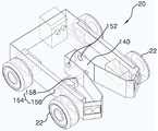
도 1은 본 발명에 따른 탐사용 로봇을 나타낸 사시도로서, 본 발명에 따른 탐사용 로봇(100)은 비행로봇(10)과, 주행로봇(20), 및 비행로봇(10)에 제공됨과 아울러 비행로봇(10)에 주행로봇(20)을 분리 가능하게 연결하는 연결수단(110)을 포함한다.1 is a perspective view of a navigation robot according to the present invention. The navigation robot 100 according to the present invention is provided to a
여기서, 도 1에 도시된 비행로봇(10)은 통상의 회전익형 무인 비행체로 이루어지며, 주행로봇(20)은 통상의 무인 지상차량으로 이루어지는데, 비행로봇(10)과 주행로봇(20)의 작동 및 탐사기능은 공지의 기술이므로 상세한 설명은 생략한다.The
도 2는 도 1에 도시된 비행로봇에 장착된 연결수단을 보인 사시도로서, 연결수단(110)은 주행로봇(20)이 올려지는 리프팅 플레이트(130)와, 리프팅 플레이트(130)를 승강시켜 주행로봇(20)을 비행로봇(10)에 고정시키는 승강 액추에이터(120)를 포함한다.The connecting
먼저, 승강 액추에이터(120)는 내부에 실린더실(도시되지 않음)이 제공되는 승강 액추에이터 바디(122)와, 승강 피스톤 로드(124)를 포함한다.First, the
승강 액추에이터 바디(122)는 도시된 바와 같이 비행로봇(10)의 하부면 상에 장착된다. 그리고 승강 피스톤 로드(124)는 승강 액추에이터 바디(122)의 실린더실 내부를 따라 안내된다. 이를 위해 승강 피스톤 로드(124)의 상단부는 승강 액추에이터 바디(122)의 실린더실 내부에 배치되고, 승강 피스톤 로드(124)의 하단부는 승강 액추에이터 바디(122)의 외측으로 노출되게 배치된다.The
이때, 승강 피스톤 로드(124)는 비행로봇(10)의 하부면 측에서 비행로봇(10)의 하부면 외측으로 수직하게 직선왕복운동 가능하게 배치되는데, 여기서 승강 피스톤 로드(124)의 구동(驅動)은 공지의 기술이므로 상세한 설명은 생략한다.At this time, the
한편, 승강 액추에이터(120)는 환형의 링 형상을 가지는 스토퍼(126)를 더 포함한다.On the other hand, the
스토퍼(126)는 도시된 바와 같이 승강 피스톤 로드(124)의 구동(驅動)에 간섭되지 않게 승강 액추에이터 바디(122)의 하단부 외주면 상에 고정 장착된다. 이러한 스토퍼(126)는 리프팅 플레이트(130)와 함께 리프팅 플레이트(130)에 올려진 주행로봇(20)을 흔들림 없이 잡아주는 기능을 수행한다.The
즉 리프팅 플레이트(130)에 올려진 주행로봇(20)은 비행로봇(10)과의 연결을 위해서 승강 액추에이터(120)의 작동에 의해 상승하게 되며, 이때 리프팅 플레이트(130)를 따라 상승하는 주행로봇(20)의 상부면은 스토퍼(126)의 하부면 상에 밀착되는데, 그 결과 주행로봇(20)은 스토퍼(126)와 리프팅 플레이트(130) 사이에 흔들림 없이 고정된다.That is, the
한편, 리프팅 플레이트(130)는 도시된 바와 같이 사각의 수평한 판 형상을 가진다. 이러한 리프팅 플레이트(130)는 승강 피스톤 로드(124)를 따라 안내되는데, 이를 위해 리프팅 플레이트(130)의 상부면 중앙부분은 승강 피스톤 로드(124)의 하단부에 고정 장착된다.On the other hand, the
그리고 리프팅 플레이트(130)에는 리프팅 플레이트(130)에 올려진 주행로봇(20)의 바퀴(22)들이 지면에 접촉되면서 구동가능하게 끼워지는 다수의 개구공(132)이 형성된다. 즉 리프팅 플레이트(130)에 올려진 주행로봇(20)의 차체는 리프팅 플레이트(130)에 지지되고 주행로봇(20)의 바퀴(22)들은 개구공(132)에 끼워지는데, 이렇게 주행로봇(20)의 바퀴(22)들이 개구공(132)에 주행가능하게 끼워짐에 따라 주행로봇(20)과 연결된 비행로봇(10)은 주행로봇(20)의 구동에 의해 건물 내부나 터널, 및 동굴 등의 지형을 주행할 수 있게 된다.The
도 3은 도 1에 도시된 주행로봇을 확대하여 사시도로서, 주행로봇(20)에는 연결수단(110)의 리프팅 플레이트(130)에 올려지면서 승강 피스톤 로드(124)에 끼워질 수 있도록 연결공(140)이 형성된다.3 is an enlarged perspective view of the traveling robot shown in Fig. 1, and the traveling
연결공(140)은 도시된 바와 같이 주행로봇(20)의 전방에서부터 주행로봇(20)의 후방 측으로 연장되게 형성된다. 즉 연결공(140)이 형성된 주행로봇(20)은 평면에서 봤을 때 대략 "⊃"자 형상을 가진다. 이때 연결공(140)은 승강 피스톤 로드(124)에 원활하게 끼워질 수 있도록 연결공(140)의 중앙부분에서부터 연결공(140)의 개구(開口) 측으로 간격이 점층적으로 넓어지게 형성된다.The
한편, 주행로봇(20)의 연결공(140)에는 비행로봇(10)과의 연결 시 승강 피스톤 로드(124)가 연결공(140)에서 이탈되지 않게 하는 잠금수단(150)이 구비된다.The connecting
잠금수단(150)은 연결공(140) 내에 제공되면서 서로 전기적으로 연결되는 센서(152)와, 잠금 액추에이터(154)를 포함한다.The locking means 150 includes a
센서(152)는 도시된 바와 같이 연결공(140)의 연장단에 인접한 측면 상에 배치된다. 이렇게 배치된 센서(152)는 연결공(140)에 끼워지는 승강 피스톤 로드(124)를 감지하고, 이를 잠금 액추에이터(154)에 신호로 출력한다.The
여기서 센서(152)로는 승강 피스톤 로드(124)의 위치를 검출할 수 있는 통상의 근접센서, 또는 빛의 밝기를 이용해 승강 피스톤 로드(124)를 검출할 수 있는 통상의 조도센서, 또는 레이저광을 이용해 승강 피스톤 로드(124)를 검출할 수 있는 통상의 레이저센서 중 어느 하나 일 수 있다.The
한편, 잠금 액추에이터(154)는 잠금 액추에이터 바디(156)와, 잠금 피스톤 로드(158)를 포함한다.On the other hand, the lock actuator 154 includes a lock actuator body 156 and a
잠금 액추에이터 바디(156)는 도시된 바와 같이 센서(152)에 검출된 승강 피스톤 로드(124)를 연결공(140)에 한정할 수 있도록 연결공(140)의 일측에 인접한 주행로봇(20) 내부에 배치된다. 그리고 잠금 피스톤 로드(158)는 잠금 액추에이터 바디(156)의 작동에 의해 연결공(140) 측으로 수평하게 출몰 가능하게 배치된다. 이렇게 연결공(140) 측으로 출몰되는 잠금 피스톤 로드(158)는 센서(152)에 의해 감지된 승강 피스톤 로드(124)를 연결공(140)에서 이탈되지 않게 하는데, 이때 승강 피스톤 로드(124)는 연결공(140)의 연장단과 잠금 피스톤 로드(158) 사이에 한정된다.The lock actuator body 156 is disposed in the vicinity of the inside of the traveling
즉, 센서(152)에 의해 승강 피스톤 로드(124)가 검출되면, 센서(152)는 검출신호를 잠금 액추에이터(154) 측으로 출력하고, 센서(152)의 검출신호가 잠금 액추에이터(154)에 입력되면, 잠금 액추에이터(154)는 잠금 피스톤 로드(158)를 연결공(140) 측으로 돌출시켜 승강 피스톤 로드(124)가 연결공(140)에서 이탈되지 않게 한다. 그리고 비행로봇(10)에서 주행로봇(20)을 분리시킬 때에는 잠금 피스톤 로드(158)는 잠금 액추에이터 바디(156) 측으로 복귀된다.That is, when the
하기에는 전술한 바와 같이 형성된 탐사용 로봇(100)의 연결 및 분리 상태를 간략하게 설명한다.Hereinafter, connection and disconnection states of the navigation robot 100 formed as described above will be briefly described.
비행로봇(10)과 주행로봇(20)을 연결시키기 위해서는, 우선 비행로봇(10)과 주행로봇(20)에 결합명령과 동시에 GPS좌표 값을 전송하여 비행로봇(10)과 주행로봇(20)을 동일지역으로 이동시킨다. 이렇게 비행로봇(10)과 주행로봇(20)이 동일지역으로 이동되면, 비행로봇(10)은 초음파신호를 360도 방향으로 송신하고, 주행로봇(20)은 초음파송신신호를 찾은 후 신호를 수신하면서 비행로봇(10)에 연결된다.The flying coordinates of the flying
이때 주행로봇(20)은 리프팅 플레이트(130)에 올려지면서 승강 피스톤 로드(124)에 끼워지는데, 주행로봇(20)의 연결공(140)에 승강 피스톤 로드(124)가 센서(152)에 의해 감지되면, 잠금 액추에이터(154)는 잠금 피스톤 로드(158)를 연결공(140) 측으로 돌출시킨다.At this time, the traveling
이러한 상태 하에서 승강 액추에이터(120)가 승강 피스톤 로드(124)를 상승시키면 주행로봇(20)은 스토퍼(126)와 리프팅 플레이트(130) 사이에 고정된다.Under this condition, when the lifting
이와 같이 비행로봇(10)에 주행로봇(20)이 연결되면, 비행로봇(10)을 작동시켜 주행로봇(20)을 원거리로 이동시킬 수 있으며, 반대로 비행로봇(10)에 주행로봇(20)이 연결된 상태 하에서 주행로봇(20)을 작동시키면 비행로봇(10)의 배터리 소모를 원천적으로 막으면서 비행로봇(10)을 원하는 위치로 이동시킬 수 있거나, 또는 주행로봇(20)과 함께 비행로봇(10)을 건물 내부나 터널, 또는 동굴 등의 지형으로 이동시킬 수 있다.When the traveling
한편, 비행로봇(10)과 주행로봇(20)의 분리되는 비행로봇(10)과 주행로봇(20)의 연결하는 방법의 역순으로 이루어진다.A method of connecting the flying
여기서 비행로봇(10)과 주행로봇(20)이 동일지역으로 이동하는 기술, 및 초음파신호에 위해 연결위치로 주행로봇(20)을 접근시키는 기술 등은 공지의 기술이므로 상세한 설명을 생략한다.Here, a technique of moving the flying
이와 같이 형성된 본 발명에 따른 탐사용 로봇(100)은 비행로봇(10)과 주행로봇(20)을 분리 가능하게 연결하는 연결수단(110)을 구비함으로써, 비행로봇(10)과 주행로봇(20)이 가지는 공간 이동의 제한성을 극복할 수 있게 한다.The navigation robot 100 according to the present invention has the connecting means 110 for detachably connecting the flying
또한 본 발명에 따른 탐사용 로봇(100)은, 주행로봇(20)이 올려지는 리프팅 플레이트(130)에 주행로봇(20)의 바퀴(22)가 구동가능하게 끼워지는 개구공(132)을 형성함으로써, 비행로봇(10)과 주행로봇(20)이 연결된 상태에서 지상을 주행할 수 있게 한다.The navigation robot 100 according to the present invention further includes an
상기와 같은 탐사용 로봇(100)은 위에서 설명된 실시예들의 구성과 작동 방식에 한정되는 것이 아니다. 상기 실시예들은 각 실시예들의 전부 또는 일부가 선택적으로 조합되어 다양한 변형이 이루어질 수 있도록 구성될 수도 있다.
The above-described navigation robot 100 is not limited to the configuration and operation of the above-described embodiments. The embodiments may be configured so that all or some of the embodiments may be selectively combined so that various modifications may be made.
100 : 탐사용 로봇110 : 연결수단
120 : 승강 액추에이터130 : 리프팅 플레이트
140 : 연결공150 : 잠금수단
152 : 센서154 : 잠금 액추에이터100: Tom robot 110: Connection means
120: lifting actuator 130: lifting plate
140: connecting hole 150: locking means
152: sensor 154: lock actuator
Claims (7)
Translated fromKorean상기 탐사용 로봇은,
상기 비행로봇과 상기 주행로봇을 분리 가능하게 연결하는 연결수단;을 포함하며,
상기 연결수단은,
상기 주행로봇이 올려지는 리프팅 플레이트; 및
상기 비행로봇의 하부면에 장착됨과 아울러 상기 리프팅 플레이트를 승강시켜 상기 주행로봇을 상기 비행로봇에 고정시키는 승강 액추에이터;를 포함하며,
상기 승강 액추에이터는,
내부에 실린더실이 제공되고 상기 비행로봇의 하부면 상에 장착되는 승강 액추에이터 바디; 및
상기 승강 액추에이터 바디의 상기 실린더실 내부를 따라 상기 비행로봇의 하부면 측에서 상기 비행로봇의 하부면 외측으로 수직하게 직선왕복운동 가능하게 배치되는 승강 피스톤 로드;를 포함하며,
상기 승강 액추에이터는 환형의 링 형상을 가지는 스토퍼;를 더 포함하며,
상기 스토퍼는 상기 승강 액추에이터 바디의 하단부 외주면 상에 고정 장착되어 상기 리프팅 플레이트와 함께 상기 리프팅 플레이트에 올려진 상기 주행로봇을 흔들림 없이 잡아주는 것을 특징으로 하는 탐사용 로봇.
In a navigation robot having a navigation robot composed of an unmanned aerial vehicle and an unmanned ground vehicle,
The navigation system according to claim 1,
And connection means for detachably connecting the flying robot and the traveling robot,
Wherein the connecting means comprises:
A lifting plate on which the traveling robot is lifted; And
And a lifting actuator mounted on a lower surface of the flying robot and lifting the lifting plate to fix the traveling robot to the flying robot,
The elevating actuator includes:
A lift actuator body provided with a cylinder chamber therein and mounted on a lower surface of the flying robot; And
And a lifting piston rod vertically and reciprocally movable from a lower surface side of the flying robot to an outer side of a lower surface of the flying robot along the inside of the cylinder chamber of the lifting actuator body,
The elevating actuator further includes a stopper having an annular ring shape,
Wherein the stopper is fixedly mounted on an outer circumferential surface of a lower end portion of the lifting actuator body to hold the traveling robot mounted on the lifting plate together with the lifting plate without shaking.
상기 리프팅 플레이트는 상기 승강 피스톤 로드를 따라 안내될 수 있도록 상부면 중앙부분이 상기 승강 피스톤 로드의 하단부에 고정 장착되며,
상기 리프팅 플레이트에는 상기 주행로봇의 바퀴들이 지면에 접촉되면서 구동가능하게 끼워지는 다수의 개구공이 형성되는 것을 특징으로 하는 탐사용 로봇.
The method according to claim 1,
The lifting plate is fixedly mounted on a lower end portion of the lifting piston rod so that a center portion of the upper surface is guided along the lifting piston rod,
Wherein the lifting plate is formed with a plurality of openings which are fitted to be able to be driven while the wheels of the traveling robot are in contact with the ground.
상기 주행로봇에는 상기 리프팅 플레이트에 올려지면서 상기 승강 액추에이터의 상기 승강 피스톤 로드에 끼워질 수 있도록 연결공이 상기 주행로봇의 전방에서부터 상기 주행로봇의 후방 측으로 연장되게 형성되는 것을 특징으로 하는 탐사용 로봇.
The method according to claim 1,
Wherein the traveling robot is formed with a connecting hole extending from a front side of the traveling robot to a rear side of the traveling robot so as to be fitted on the lifting piston rod of the elevating actuator while being mounted on the lifting plate.
상기 연결공에는 상기 비행로봇과의 연결 시 상기 승강 피스톤 로드가 상기 연결공에서 이탈되지 않게 하는 잠금수단;이 구비되고,
상기 잠금수단은,
상기 연결공의 연장단에 인접한 측면 상에 배치되어 상기 연결공에 끼워지는 상기 승강 피스톤 로드를 감지하는 센서; 및
상기 센서에 의해 감지된 상기 승강 피스톤 로드를 상기 연결공에서 이탈되지 않게 하는 잠금 액추에이터;를 포함하는 것을 특징으로 하는 탐사용 로봇.
The method of claim 5,
And a locking means for preventing the lifting piston rod from being detached from the connecting hole when the connecting robot is connected to the flying robot,
Wherein the locking means comprises:
A sensor disposed on a side adjacent to the extending end of the connecting hole to sense the lifting piston rod fitted in the connecting hole; And
And a locking actuator for preventing the elevating piston rod detected by the sensor from being detached from the connection hole.
상기 잠금 액추에이터는,
상기 센서에 검출된 상기 승강 피스톤 로드를 상기 연결공에 한정할 수 있도록 상기 연결공의 일측에 인접한 상기 주행로봇 내부에 배치되는 잠금 액추에이터 바디; 및
상기 잠금 액추에이터 바디의 작동에 의해 상기 연결공 측으로 수평하게 출몰 가능하게 배치되는 잠금 피스톤 로드;를 포함하는 것을 특징으로 하는 탐사용 로봇.The method of claim 6,
Wherein the lock actuator comprises:
A lock actuator body disposed within the traveling robot adjacent to one side of the connecting hole so as to limit the elevating piston rod detected by the sensor to the connecting hole; And
And a locking piston rod disposed horizontally to be able to protrude / retract horizontally toward the connection hole by operation of the lock actuator body.
Priority Applications (1)
| Application Number | Priority Date | Filing Date | Title |
|---|---|---|---|
| KR20140019429AKR101491076B1 (en) | 2014-02-20 | 2014-02-20 | Exploreration robot |
Applications Claiming Priority (1)
| Application Number | Priority Date | Filing Date | Title |
|---|---|---|---|
| KR20140019429AKR101491076B1 (en) | 2014-02-20 | 2014-02-20 | Exploreration robot |
Publications (1)
| Publication Number | Publication Date |
|---|---|
| KR101491076B1true KR101491076B1 (en) | 2015-02-10 |
Family
ID=52591615
Family Applications (1)
| Application Number | Title | Priority Date | Filing Date |
|---|---|---|---|
| KR20140019429AActiveKR101491076B1 (en) | 2014-02-20 | 2014-02-20 | Exploreration robot |
Country Status (1)
| Country | Link |
|---|---|
| KR (1) | KR101491076B1 (en) |
Cited By (10)
| Publication number | Priority date | Publication date | Assignee | Title |
|---|---|---|---|---|
| KR101972698B1 (en)* | 2018-03-26 | 2019-04-25 | 이재관 | Exploration device for survey |
| CN110209176A (en)* | 2019-06-28 | 2019-09-06 | 北京史河科技有限公司 | A kind of robot |
| JP2020164161A (en)* | 2017-08-31 | 2020-10-08 | 浙江吉利控股集団有限公司Zhejiang Geely Holding Group Co.,Ltd. | Flying car system and flying car sharing method |
| CN111846259A (en)* | 2019-04-24 | 2020-10-30 | 苏州翼搏特智能科技有限公司 | A docking mechanism for an aircraft and a crawling robot |
| CN112249322A (en)* | 2020-10-19 | 2021-01-22 | 东风汽车集团有限公司 | A vehicle portable rotary-wing single-person aircraft and vehicle |
| KR20210098064A (en) | 2020-01-31 | 2021-08-10 | 한국로봇융합연구원 | Monitoring robot system in the culvert or atypical space |
| CN114252642A (en)* | 2022-02-24 | 2022-03-29 | 江西省自然资源事业发展中心 | Dynamic monitoring device and monitoring method for natural resources |
| US11472498B2 (en) | 2018-11-29 | 2022-10-18 | Saudi Arabian Oil Company | Perching UAV with releasable crawler |
| KR20230086213A (en)* | 2021-12-08 | 2023-06-15 | 한국항공우주연구원 | 3D logistics identification system and 3D logistics identification method using the same |
| WO2025154073A1 (en)* | 2024-01-17 | 2025-07-24 | Wespace Technologies Ltd | A vehicle for terrestrial or extraterrestrial use |
Citations (2)
| Publication number | Priority date | Publication date | Assignee | Title |
|---|---|---|---|---|
| JP2010047109A (en)* | 2008-08-21 | 2010-03-04 | Mitsubishi Heavy Ind Ltd | Unmanned aircraft system and method for operating the same |
| JP2013531573A (en)* | 2010-05-26 | 2013-08-08 | エアロヴァイロンメント インコーポレイテッド | Reconfigurable battery-powered drone system |
- 2014
- 2014-02-20KRKR20140019429Apatent/KR101491076B1/enactiveActive
Patent Citations (2)
| Publication number | Priority date | Publication date | Assignee | Title |
|---|---|---|---|---|
| JP2010047109A (en)* | 2008-08-21 | 2010-03-04 | Mitsubishi Heavy Ind Ltd | Unmanned aircraft system and method for operating the same |
| JP2013531573A (en)* | 2010-05-26 | 2013-08-08 | エアロヴァイロンメント インコーポレイテッド | Reconfigurable battery-powered drone system |
Cited By (14)
| Publication number | Priority date | Publication date | Assignee | Title |
|---|---|---|---|---|
| JP2020164161A (en)* | 2017-08-31 | 2020-10-08 | 浙江吉利控股集団有限公司Zhejiang Geely Holding Group Co.,Ltd. | Flying car system and flying car sharing method |
| US11661127B2 (en) | 2017-08-31 | 2023-05-30 | Zhejiang Geely Holding Group Co., Ltd. | Modular ground vehicle and flight vehicle sharing system |
| KR101972698B1 (en)* | 2018-03-26 | 2019-04-25 | 이재관 | Exploration device for survey |
| US11472498B2 (en) | 2018-11-29 | 2022-10-18 | Saudi Arabian Oil Company | Perching UAV with releasable crawler |
| US11584458B2 (en) | 2018-11-29 | 2023-02-21 | Saudi Arabian Oil Company | Inspection method using a perching UAV with a releasable crawler |
| CN111846259A (en)* | 2019-04-24 | 2020-10-30 | 苏州翼搏特智能科技有限公司 | A docking mechanism for an aircraft and a crawling robot |
| CN110209176A (en)* | 2019-06-28 | 2019-09-06 | 北京史河科技有限公司 | A kind of robot |
| KR20210098064A (en) | 2020-01-31 | 2021-08-10 | 한국로봇융합연구원 | Monitoring robot system in the culvert or atypical space |
| CN112249322A (en)* | 2020-10-19 | 2021-01-22 | 东风汽车集团有限公司 | A vehicle portable rotary-wing single-person aircraft and vehicle |
| KR20230086213A (en)* | 2021-12-08 | 2023-06-15 | 한국항공우주연구원 | 3D logistics identification system and 3D logistics identification method using the same |
| KR102773045B1 (en)* | 2021-12-08 | 2025-02-26 | 한국항공우주연구원 | 3D logistics identification system and 3D logistics identification method using the same |
| CN114252642A (en)* | 2022-02-24 | 2022-03-29 | 江西省自然资源事业发展中心 | Dynamic monitoring device and monitoring method for natural resources |
| CN114252642B (en)* | 2022-02-24 | 2023-03-14 | 江西省自然资源事业发展中心 | Dynamic monitoring device and monitoring method for natural resources |
| WO2025154073A1 (en)* | 2024-01-17 | 2025-07-24 | Wespace Technologies Ltd | A vehicle for terrestrial or extraterrestrial use |
Similar Documents
| Publication | Publication Date | Title |
|---|---|---|
| KR101491076B1 (en) | Exploreration robot | |
| KR102089067B1 (en) | Multi-drone system and operating method thereof | |
| US11860305B2 (en) | Light detection and ranging (LIDAR) device having multiple receivers | |
| US10067502B1 (en) | Service drone configuration based on a serviceable vehicle-component fault condition | |
| JP6379575B2 (en) | Unmanned aircraft, unmanned aircraft control method, and control system | |
| US11054835B2 (en) | Vehicle collision avoidance | |
| US20200039373A1 (en) | Systems and methods for charging an unmanned aerial vehicle with a host vehicle | |
| Papachristos et al. | The power-tethered UAV-UGV team: A collaborative strategy for navigation in partially-mapped environments | |
| AU2023200354A1 (en) | Materials handling vehicle obstacle scanning tools | |
| US20220258818A1 (en) | Autonomous mobile robot | |
| US10139816B2 (en) | Device for maneuvering ground support equipment on an airport stand | |
| US20170201738A1 (en) | Senising on uavs for mapping and obstacle avoidance | |
| US20170372625A1 (en) | Unmanned aerial vehicle | |
| CN109002046B (en) | A mobile robot navigation system and navigation method | |
| US10597273B2 (en) | Carrier vehicle | |
| GB2557715A (en) | Unmanned aerial vehicles | |
| JP2014104797A (en) | Indoor inspection system | |
| CN204364888U (en) | Long-distance Control assembly and system | |
| KR20200088908A (en) | Close navigation of unmanned vehicles | |
| CN106774343A (en) | A kind of pilotless automobile transported for wounded's rescue | |
| CN107636549A (en) | Method, device and unmanned aerial vehicle for controlling a movable object | |
| Cantelli et al. | UAV/UGV cooperation to improve navigation capabilities of a mobile robot in unstructured environments | |
| CN113253743A (en) | Near-end capturing method for reconfigurable autonomous docking process of unmanned vehicle | |
| KR20190075432A (en) | Charging station for unmanned aerial vehicles and system including the same | |
| AU2016101054A4 (en) | System for Controlling RC toy car using Laser Gun controller |
Legal Events
| Date | Code | Title | Description |
|---|---|---|---|
| PA0109 | Patent application | Patent event code:PA01091R01D Comment text:Patent Application Patent event date:20140220 | |
| PA0201 | Request for examination | ||
| E902 | Notification of reason for refusal | ||
| PE0902 | Notice of grounds for rejection | Comment text:Notification of reason for refusal Patent event date:20141218 Patent event code:PE09021S01D | |
| E701 | Decision to grant or registration of patent right | ||
| GRNT | Written decision to grant | ||
| PE0701 | Decision of registration | Patent event code:PE07011S01D Comment text:Decision to Grant Registration Patent event date:20150202 | |
| PR0701 | Registration of establishment | Comment text:Registration of Establishment Patent event date:20150202 Patent event code:PR07011E01D | |
| PR1002 | Payment of registration fee | Payment date:20150202 End annual number:3 Start annual number:1 | |
| PG1601 | Publication of registration | ||
| FPAY | Annual fee payment | Payment date:20180126 Year of fee payment:4 | |
| PR1001 | Payment of annual fee | Payment date:20180126 Start annual number:4 End annual number:4 | |
| FPAY | Annual fee payment | Payment date:20190207 Year of fee payment:5 | |
| PR1001 | Payment of annual fee | Payment date:20190207 Start annual number:5 End annual number:5 | |
| FPAY | Annual fee payment | Payment date:20200102 Year of fee payment:6 | |
| PR1001 | Payment of annual fee | Payment date:20200102 Start annual number:6 End annual number:6 | |
| PR1001 | Payment of annual fee | Payment date:20210728 Start annual number:7 End annual number:7 | |
| PR1001 | Payment of annual fee | Payment date:20220110 Start annual number:8 End annual number:8 | |
| PR1001 | Payment of annual fee | Payment date:20221124 Start annual number:9 End annual number:9 | |
| PR1001 | Payment of annual fee | Payment date:20240304 Start annual number:10 End annual number:10 |