KR101489519B1 - Implantable device - Google Patents
Implantable deviceDownload PDFInfo
- Publication number
- KR101489519B1 KR101489519B1KR1020097006956AKR20097006956AKR101489519B1KR 101489519 B1KR101489519 B1KR 101489519B1KR 1020097006956 AKR1020097006956 AKR 1020097006956AKR 20097006956 AKR20097006956 AKR 20097006956AKR 101489519 B1KR101489519 B1KR 101489519B1
- Authority
- KR
- South Korea
- Prior art keywords
- implantable device
- sub
- carrier structure
- wire
- configuration
- Prior art date
- Legal status (The legal status is an assumption and is not a legal conclusion. Google has not performed a legal analysis and makes no representation as to the accuracy of the status listed.)
- Expired - Fee Related
Links
Images


Classifications
- A—HUMAN NECESSITIES
- A61—MEDICAL OR VETERINARY SCIENCE; HYGIENE
- A61F—FILTERS IMPLANTABLE INTO BLOOD VESSELS; PROSTHESES; DEVICES PROVIDING PATENCY TO, OR PREVENTING COLLAPSING OF, TUBULAR STRUCTURES OF THE BODY, e.g. STENTS; ORTHOPAEDIC, NURSING OR CONTRACEPTIVE DEVICES; FOMENTATION; TREATMENT OR PROTECTION OF EYES OR EARS; BANDAGES, DRESSINGS OR ABSORBENT PADS; FIRST-AID KITS
- A61F2/00—Filters implantable into blood vessels; Prostheses, i.e. artificial substitutes or replacements for parts of the body; Appliances for connecting them with the body; Devices providing patency to, or preventing collapsing of, tubular structures of the body, e.g. stents
- A61F2/02—Prostheses implantable into the body
- A61F2/04—Hollow or tubular parts of organs, e.g. bladders, tracheae, bronchi or bile ducts
- A—HUMAN NECESSITIES
- A61—MEDICAL OR VETERINARY SCIENCE; HYGIENE
- A61B—DIAGNOSIS; SURGERY; IDENTIFICATION
- A61B17/00—Surgical instruments, devices or methods
- A—HUMAN NECESSITIES
- A61—MEDICAL OR VETERINARY SCIENCE; HYGIENE
- A61B—DIAGNOSIS; SURGERY; IDENTIFICATION
- A61B17/00—Surgical instruments, devices or methods
- A61B17/0057—Implements for plugging an opening in the wall of a hollow or tubular organ, e.g. for sealing a vessel puncture or closing a cardiac septal defect
- A—HUMAN NECESSITIES
- A61—MEDICAL OR VETERINARY SCIENCE; HYGIENE
- A61B—DIAGNOSIS; SURGERY; IDENTIFICATION
- A61B17/00—Surgical instruments, devices or methods
- A61B17/11—Surgical instruments, devices or methods for performing anastomosis; Buttons for anastomosis
- A—HUMAN NECESSITIES
- A61—MEDICAL OR VETERINARY SCIENCE; HYGIENE
- A61B—DIAGNOSIS; SURGERY; IDENTIFICATION
- A61B17/00—Surgical instruments, devices or methods
- A61B17/12—Surgical instruments, devices or methods for ligaturing or otherwise compressing tubular parts of the body, e.g. blood vessels or umbilical cord
- A61B17/12022—Occluding by internal devices, e.g. balloons or releasable wires
- A61B17/12027—Type of occlusion
- A61B17/12031—Type of occlusion complete occlusion
- A—HUMAN NECESSITIES
- A61—MEDICAL OR VETERINARY SCIENCE; HYGIENE
- A61B—DIAGNOSIS; SURGERY; IDENTIFICATION
- A61B17/00—Surgical instruments, devices or methods
- A61B17/12—Surgical instruments, devices or methods for ligaturing or otherwise compressing tubular parts of the body, e.g. blood vessels or umbilical cord
- A61B17/12022—Occluding by internal devices, e.g. balloons or releasable wires
- A61B17/12027—Type of occlusion
- A61B17/12036—Type of occlusion partial occlusion
- A—HUMAN NECESSITIES
- A61—MEDICAL OR VETERINARY SCIENCE; HYGIENE
- A61B—DIAGNOSIS; SURGERY; IDENTIFICATION
- A61B17/00—Surgical instruments, devices or methods
- A61B17/12—Surgical instruments, devices or methods for ligaturing or otherwise compressing tubular parts of the body, e.g. blood vessels or umbilical cord
- A61B17/12022—Occluding by internal devices, e.g. balloons or releasable wires
- A61B17/12099—Occluding by internal devices, e.g. balloons or releasable wires characterised by the location of the occluder
- A61B17/12109—Occluding by internal devices, e.g. balloons or releasable wires characterised by the location of the occluder in a blood vessel
- A61B17/12113—Occluding by internal devices, e.g. balloons or releasable wires characterised by the location of the occluder in a blood vessel within an aneurysm
- A61B17/12118—Occluding by internal devices, e.g. balloons or releasable wires characterised by the location of the occluder in a blood vessel within an aneurysm for positioning in conjunction with a stent
- A—HUMAN NECESSITIES
- A61—MEDICAL OR VETERINARY SCIENCE; HYGIENE
- A61B—DIAGNOSIS; SURGERY; IDENTIFICATION
- A61B17/00—Surgical instruments, devices or methods
- A61B17/12—Surgical instruments, devices or methods for ligaturing or otherwise compressing tubular parts of the body, e.g. blood vessels or umbilical cord
- A61B17/12022—Occluding by internal devices, e.g. balloons or releasable wires
- A61B17/12099—Occluding by internal devices, e.g. balloons or releasable wires characterised by the location of the occluder
- A61B17/12122—Occluding by internal devices, e.g. balloons or releasable wires characterised by the location of the occluder within the heart
- A—HUMAN NECESSITIES
- A61—MEDICAL OR VETERINARY SCIENCE; HYGIENE
- A61B—DIAGNOSIS; SURGERY; IDENTIFICATION
- A61B17/00—Surgical instruments, devices or methods
- A61B17/12—Surgical instruments, devices or methods for ligaturing or otherwise compressing tubular parts of the body, e.g. blood vessels or umbilical cord
- A61B17/12022—Occluding by internal devices, e.g. balloons or releasable wires
- A61B17/12131—Occluding by internal devices, e.g. balloons or releasable wires characterised by the type of occluding device
- A61B17/12136—Balloons
- A—HUMAN NECESSITIES
- A61—MEDICAL OR VETERINARY SCIENCE; HYGIENE
- A61B—DIAGNOSIS; SURGERY; IDENTIFICATION
- A61B17/00—Surgical instruments, devices or methods
- A61B17/12—Surgical instruments, devices or methods for ligaturing or otherwise compressing tubular parts of the body, e.g. blood vessels or umbilical cord
- A61B17/12022—Occluding by internal devices, e.g. balloons or releasable wires
- A61B17/12131—Occluding by internal devices, e.g. balloons or releasable wires characterised by the type of occluding device
- A61B17/12168—Occluding by internal devices, e.g. balloons or releasable wires characterised by the type of occluding device having a mesh structure
- A61B17/12172—Occluding by internal devices, e.g. balloons or releasable wires characterised by the type of occluding device having a mesh structure having a pre-set deployed three-dimensional shape
- A—HUMAN NECESSITIES
- A61—MEDICAL OR VETERINARY SCIENCE; HYGIENE
- A61F—FILTERS IMPLANTABLE INTO BLOOD VESSELS; PROSTHESES; DEVICES PROVIDING PATENCY TO, OR PREVENTING COLLAPSING OF, TUBULAR STRUCTURES OF THE BODY, e.g. STENTS; ORTHOPAEDIC, NURSING OR CONTRACEPTIVE DEVICES; FOMENTATION; TREATMENT OR PROTECTION OF EYES OR EARS; BANDAGES, DRESSINGS OR ABSORBENT PADS; FIRST-AID KITS
- A61F2/00—Filters implantable into blood vessels; Prostheses, i.e. artificial substitutes or replacements for parts of the body; Appliances for connecting them with the body; Devices providing patency to, or preventing collapsing of, tubular structures of the body, e.g. stents
- A61F2/01—Filters implantable into blood vessels
- A—HUMAN NECESSITIES
- A61—MEDICAL OR VETERINARY SCIENCE; HYGIENE
- A61L—METHODS OR APPARATUS FOR STERILISING MATERIALS OR OBJECTS IN GENERAL; DISINFECTION, STERILISATION OR DEODORISATION OF AIR; CHEMICAL ASPECTS OF BANDAGES, DRESSINGS, ABSORBENT PADS OR SURGICAL ARTICLES; MATERIALS FOR BANDAGES, DRESSINGS, ABSORBENT PADS OR SURGICAL ARTICLES
- A61L31/00—Materials for other surgical articles, e.g. stents, stent-grafts, shunts, surgical drapes, guide wires, materials for adhesion prevention, occluding devices, surgical gloves, tissue fixation devices
- A61L31/08—Materials for coatings
- A—HUMAN NECESSITIES
- A61—MEDICAL OR VETERINARY SCIENCE; HYGIENE
- A61B—DIAGNOSIS; SURGERY; IDENTIFICATION
- A61B17/00—Surgical instruments, devices or methods
- A61B17/0057—Implements for plugging an opening in the wall of a hollow or tubular organ, e.g. for sealing a vessel puncture or closing a cardiac septal defect
- A61B2017/00575—Implements for plugging an opening in the wall of a hollow or tubular organ, e.g. for sealing a vessel puncture or closing a cardiac septal defect for closure at remote site, e.g. closing atrial septum defects
- A61B2017/00592—Elastic or resilient implements
- A—HUMAN NECESSITIES
- A61—MEDICAL OR VETERINARY SCIENCE; HYGIENE
- A61B—DIAGNOSIS; SURGERY; IDENTIFICATION
- A61B17/00—Surgical instruments, devices or methods
- A61B17/0057—Implements for plugging an opening in the wall of a hollow or tubular organ, e.g. for sealing a vessel puncture or closing a cardiac septal defect
- A61B2017/00575—Implements for plugging an opening in the wall of a hollow or tubular organ, e.g. for sealing a vessel puncture or closing a cardiac septal defect for closure at remote site, e.g. closing atrial septum defects
- A61B2017/00597—Implements comprising a membrane
- A—HUMAN NECESSITIES
- A61—MEDICAL OR VETERINARY SCIENCE; HYGIENE
- A61B—DIAGNOSIS; SURGERY; IDENTIFICATION
- A61B17/00—Surgical instruments, devices or methods
- A61B17/0057—Implements for plugging an opening in the wall of a hollow or tubular organ, e.g. for sealing a vessel puncture or closing a cardiac septal defect
- A61B2017/00575—Implements for plugging an opening in the wall of a hollow or tubular organ, e.g. for sealing a vessel puncture or closing a cardiac septal defect for closure at remote site, e.g. closing atrial septum defects
- A61B2017/00606—Implements H-shaped in cross-section, i.e. with occluders on both sides of the opening
- A—HUMAN NECESSITIES
- A61—MEDICAL OR VETERINARY SCIENCE; HYGIENE
- A61B—DIAGNOSIS; SURGERY; IDENTIFICATION
- A61B17/00—Surgical instruments, devices or methods
- A61B17/0057—Implements for plugging an opening in the wall of a hollow or tubular organ, e.g. for sealing a vessel puncture or closing a cardiac septal defect
- A61B2017/00575—Implements for plugging an opening in the wall of a hollow or tubular organ, e.g. for sealing a vessel puncture or closing a cardiac septal defect for closure at remote site, e.g. closing atrial septum defects
- A61B2017/00615—Implements with an occluder on one side of the opening and holding means therefor on the other
- A—HUMAN NECESSITIES
- A61—MEDICAL OR VETERINARY SCIENCE; HYGIENE
- A61B—DIAGNOSIS; SURGERY; IDENTIFICATION
- A61B17/00—Surgical instruments, devices or methods
- A61B17/0057—Implements for plugging an opening in the wall of a hollow or tubular organ, e.g. for sealing a vessel puncture or closing a cardiac septal defect
- A61B2017/00575—Implements for plugging an opening in the wall of a hollow or tubular organ, e.g. for sealing a vessel puncture or closing a cardiac septal defect for closure at remote site, e.g. closing atrial septum defects
- A61B2017/00628—T-shaped occluders
- A—HUMAN NECESSITIES
- A61—MEDICAL OR VETERINARY SCIENCE; HYGIENE
- A61B—DIAGNOSIS; SURGERY; IDENTIFICATION
- A61B17/00—Surgical instruments, devices or methods
- A61B2017/00831—Material properties
- A61B2017/00867—Material properties shape memory effect
- A—HUMAN NECESSITIES
- A61—MEDICAL OR VETERINARY SCIENCE; HYGIENE
- A61B—DIAGNOSIS; SURGERY; IDENTIFICATION
- A61B17/00—Surgical instruments, devices or methods
- A61B2017/00831—Material properties
- A61B2017/00893—Material properties pharmaceutically effective
- A—HUMAN NECESSITIES
- A61—MEDICAL OR VETERINARY SCIENCE; HYGIENE
- A61B—DIAGNOSIS; SURGERY; IDENTIFICATION
- A61B17/00—Surgical instruments, devices or methods
- A61B17/11—Surgical instruments, devices or methods for performing anastomosis; Buttons for anastomosis
- A61B2017/1107—Surgical instruments, devices or methods for performing anastomosis; Buttons for anastomosis for blood vessels
- A—HUMAN NECESSITIES
- A61—MEDICAL OR VETERINARY SCIENCE; HYGIENE
- A61B—DIAGNOSIS; SURGERY; IDENTIFICATION
- A61B17/00—Surgical instruments, devices or methods
- A61B17/11—Surgical instruments, devices or methods for performing anastomosis; Buttons for anastomosis
- A61B2017/1135—End-to-side connections, e.g. T- or Y-connections
- A—HUMAN NECESSITIES
- A61—MEDICAL OR VETERINARY SCIENCE; HYGIENE
- A61B—DIAGNOSIS; SURGERY; IDENTIFICATION
- A61B17/00—Surgical instruments, devices or methods
- A61B17/11—Surgical instruments, devices or methods for performing anastomosis; Buttons for anastomosis
- A61B2017/1139—Side-to-side connections, e.g. shunt or X-connections
- A—HUMAN NECESSITIES
- A61—MEDICAL OR VETERINARY SCIENCE; HYGIENE
- A61B—DIAGNOSIS; SURGERY; IDENTIFICATION
- A61B17/00—Surgical instruments, devices or methods
- A61B17/12—Surgical instruments, devices or methods for ligaturing or otherwise compressing tubular parts of the body, e.g. blood vessels or umbilical cord
- A61B17/12022—Occluding by internal devices, e.g. balloons or releasable wires
- A61B2017/1205—Introduction devices
- A61B2017/12054—Details concerning the detachment of the occluding device from the introduction device
- A—HUMAN NECESSITIES
- A61—MEDICAL OR VETERINARY SCIENCE; HYGIENE
- A61B—DIAGNOSIS; SURGERY; IDENTIFICATION
- A61B90/00—Instruments, implements or accessories specially adapted for surgery or diagnosis and not covered by any of the groups A61B1/00 - A61B50/00, e.g. for luxation treatment or for protecting wound edges
- A61B90/39—Markers, e.g. radio-opaque or breast lesions markers
Landscapes
- Health & Medical Sciences (AREA)
- Life Sciences & Earth Sciences (AREA)
- Surgery (AREA)
- Veterinary Medicine (AREA)
- Heart & Thoracic Surgery (AREA)
- Animal Behavior & Ethology (AREA)
- General Health & Medical Sciences (AREA)
- Public Health (AREA)
- Engineering & Computer Science (AREA)
- Biomedical Technology (AREA)
- Medical Informatics (AREA)
- Molecular Biology (AREA)
- Nuclear Medicine, Radiotherapy & Molecular Imaging (AREA)
- Vascular Medicine (AREA)
- Reproductive Health (AREA)
- Cardiology (AREA)
- Neurosurgery (AREA)
- Epidemiology (AREA)
- Oral & Maxillofacial Surgery (AREA)
- Transplantation (AREA)
- Pathology (AREA)
- Gastroenterology & Hepatology (AREA)
- Pulmonology (AREA)
- Prostheses (AREA)
- Surgical Instruments (AREA)
Abstract
Translated fromKoreanDescription
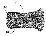
Translated fromKorean본 발명은 인체 및/또는 동물체에서 결손구(defect opening), 공동(cavity), 기관로(organ passage) 등의 폐쇄 또는 부분적인 폐쇄를 위해 사용하거나 또는 벽체, 기관, 공동 등 사이에 형성된 연통구(communicating opening)를 제공하기 위한 이식형 장치에 관한 것으로, 제 1 형태에서는 축(X)을 따른 길이 대 폭(transverse extent)의 비율이 크고 제 2 형태에서는 상기 축(X)을 따른 길이 대 폭의 비율이 보다 작은 캐리어 구조체(carrier structure)를 포함하되, 상기 캐리어 구조체는 근위부(proximal part) 및 원위부(distal part)를 가지고 웨프트(weft) 및/또는 메쉬(mesh) 및/또는 층상 구조의 직물(layered cloth) 및/또는 거즈(gauze) 방식으로 형성된다.The present invention can be used for closing or partially closing a defect opening, a cavity, an organ passage or the like in a human body and / or an animal, The present invention relates to an implantable device for providing a communicating opening in which a ratio of transverse extent along the axis X is large in the first form and a ratio of length to width along the axis X in the second form is large, Wherein the carrier structure has a proximal part and a distal part and has a weft and / or mesh and / or laminar structure, wherein the carrier structure has a proximal part and a distal part. A layered cloth and / or a gauze method.
상기 축은 일반적으로 이식형 장치가 장형(elongated)인 경우에 제공되는 이식형 장치의 세로축이다. 이러한 종류의 이식형 장치는 종래 기술로부터 알려진다. 예를 들어, DE 103 02 447은 제 2 형태에서의 근위부 및/또는 원위부가 실질적으로 평평한, 디스크 형태 또는 환상의 구성이고, 원위부 또는 근위부를 연결하고 내부 공간을 둘러싸는 중간 섹션으로부터 바깥을 향하여 구부러지는 이식형 장치를 개시한다. 막 부재로서 역할을 하는 추가적인 섬유 또는 메쉬부는 이식형 장치 내에 채택될 수 있다. 이러한 막 부재의 제공은, 예를 들어 인간의 심장 내의 결손구가 폐쇄될 수 있는 것을 의미한다. 조직이 여기에서 성장할 수 있다.The axis is generally the longitudinal axis of the implantable device provided when the implantable device is elongated. This type of implantable device is known from the prior art. For example, DE 103 02 447 discloses a device in which a proximal and / or distal portion in a second form is a substantially flat, disc-shaped or annular configuration and which is connected to a distal or proximal portion, Discloses a portable implantable device. Additional fibers or mesh portions serving as membrane members may be employed within the implantable device. The provision of such a membrane member means that, for example, a defect in the heart of a human can be closed. Organizations can grow here.
또한, DE 100 00 137 A1은 제 2 형태가 거의 디스크 부재 사이의 결손구 주위의 영역을 수용하기 위하여 근위 디스크 부재 및 원위 디스크 부재가 있는 이중 디스크 형태인, 인체 또는 동물체의 결손구를 폐쇄하기 위한 이식형 장치를 개시한다. 캐리어 구조체가 컷 튜브부(cut tube portion)로부터 생산되는 것을 고려할 때, 실질적으로 접합 없는 하나의 부품이다. 다시, 이식형 장치 내에 막이 제공될 수 있고, 그 막은 이식형 장치의 상이한 측면에 배치될 수 있거나 또는 적당한 개구가 있는 양말과 같이 그 자체가 이식형 장치 위에 변위 시스템을 위해 끌어 당겨질 수 있다.
또한, DE 103 38 702 B1은 근위 및 원위 잔류 영역에는 그 사이에 배치되는 실리더형 둘레부(limb)가 제공되되, 근위 잔류 영역은 근위 말단을 향하여 개방하여 있는 형태인 대응 이식형 장치를 개시한다. 상기 이식형 장치의 원위 잔류 영역의 실(thread) 또는 와이어의 말단은 홀더와 결합된다. 더욱이, 션트(shunt)를 완벽하게 폐쇄하기 위한 위브 인레이(weave inlay)가 실린더형 둘레부 또는 근위 잔류 영역 내에 배치될 수 있다.In addition,
또한, 이식형 장치는 예를 들어 US 5,846,162 및 US 5,725,552로부터 공지되며, 모두 종(bell) 형상으로 이루어진다. 또한, WO 93/13712는 격벽 결손의 폐쇄를 위해 이식되는 조건이 이중 콘 또는 이중 디스크 구성을 띠고, 이 경우 외부 구조가 함께 직접 연결되는 않는 와이어 부재로부터 형성된다. 이는 세일(sail)부로 엮이되, 세일부는 폐쇄될 결손에 대응하는 반지름에서 함께 꿰매어진다. 시스템은 다수의 구성요소 부재로 이루어진 이식부가 높은 수준의 조립 복잡성 및 지출을 요구한다는 점에서 불리하다.Also, implantable devices are known, for example, from US 5,846,162 and US 5,725,552, all of which are in bell shape. WO 93/13712 also discloses that conditions for implantation for the closure of bulkhead defects are formed from a wire member having a dual cone or double disc configuration, in which case the outer structure is not directly connected together. It is woven into the sail section, and the sail section is tucked together at a radius corresponding to the defect to be closed. The system is disadvantageous in that the implantation of a number of component elements requires a high level of assembly complexity and expenditure.
WO 95/27448은 혈관 필터로서 사용되는 격벽 폐쇄를 위한 로드 베어링(load-bearing) 구조로서 사용될 이식부를 개시한다. 이러한 배치에 있어서, 상대적으로 장형의 이중 원뿔은 일련의 개별적인 와이어들로부터 형성되고, 본 종래 기술에서는 원뿔이 뼈에 의해 상호 연결되고, 또 다른 실시 형태에서는 원뿔이 광대버섯과 유사하게 동일한 방향성을 갖는다.WO 95/27448 discloses an implant for use as a load-bearing structure for septum closure used as a vascular filter. In this arrangement, the relatively elongated double cone is formed from a series of individual wires, in which the cones are interconnected by the bones, and in another embodiment the cones have the same orientation similar to the broad mushrooms .
US 5,443,727 A는 예를 들어 심방 격벽 결손(ASD) 또는 심실 격벽 결손(VSD)과 같은 심장의 큰 결손을 폐쇄하기 위한 이식부를 개시한다. 이 경우, 일종의 스크린이 격벽 결손의 전방에 배치되고, 각각의 와이어로부터 생성되는 각 4개의 루프로부터 실질적으로 형성되고 대응되는 폐쇄부로서 결손부가 결속되며, 이는 카테터로부터 배출되면서 전개되고, 스크린에서 측면을 통하여 이식부가 미끄러지는 것을 방지하도록 의도된다. 폐쇄 이식부는 "X" 형태로 코팅된 와이어 골격(skeleton)을 포함하고, 조정 가능 루프뿐만 아니라 폼 디스크에 적용되고 와이어 골격의 중앙에 맞추어지는 전개 가능한 폼(foam) 수지 디스크를 더 포함한다.US 5,443, 727 A discloses an implant for closing a large defect in the heart, such as, for example, atrial septal defect (ASD) or ventricular septal defect (VSD). In this case, a sort of screen is disposed in front of the barrier defect, and substantially formed from each of the four loops generated from each wire and bound together as a corresponding closing part, which is evolved as it exits the catheter, Lt; RTI ID = 0.0 > a < / RTI > The closed implant includes a skeleton coated in an "X" form, and includes an adjustable loop as well as a deployable foam resin disk applied to the foam disk and centered on the wire skeleton.
WO 97/28774는 카테터로부터 배출되면, 이에 부여된 제 2 형태를 제공함으로써 그리고 넓은 영역에서 결손의 크기에 적합한 그 자체의 탄성력에 의하여 자동으로 전개되는 이식부를 개시한다. 부여된 구조체는 결손 주위의 영역에 대하여 결손의 양쪽 측면에서 이중 디스크의 방식으로 클램핑된다. 이식부는 예를 들어 초음파 용접 또는 땜질과 같은 적당한 접합 방법에 의해 함께 접합되는 와이어 부재의 직렬의 형태로부터 형성된다. 이식부에는 와이어 부재에 고정되는 덮개가 더 제공된다.WO 97/28774 discloses an implant which is evacuated from the catheter and automatically deployed by its own elasticity, which is adapted to the magnitude of the defect in a large area, by providing a second form imparted thereto. The imparted structure is clamped in the manner of a double disc on both sides of the defect with respect to the area around the defect. The implants are formed from a series of forms of wire members joined together by suitable bonding methods such as, for example, ultrasonic welding or brazing. The cover is further provided with a cover fixed to the wire member.
또한, WO 99/12478 A1은 덤벨 또는 요요 형상의, 복수의 섞여 짜여진(interwoven) 니티놀(Nitinol) 와이어를 포함하는 메쉬가 제공되는 대응 이식형 장치를 개시한다. 이식형 장치는, 그 제 1 형태에서, 두 개의 단부는 실질적으로 슬리브(sleeve)에 각각 유지되고 용접되는 헐거운 와이어 말단을 구비하는 둥근 메쉬의 형태이다. 그것을 제공함으로써, 이식형 장치는 그 근위부 및 원위부에서 돌출된 슬리브를 가지게 형성된다.WO 99/12478 A1 also discloses a corresponding implantable device provided with a mesh comprising a plurality of interwoven Nitinol wires in the form of dumbbells or yo-yo. The implantable device is, in its first form, in the form of a round mesh with loose wire ends, the two ends of which are held and welded substantially respectively to a sleeve. By providing it, the implantable device is formed with a sleeve protruding from its proximal and distal portions.
US 2003/0191495 A1은 그것들 사이에 부재를 연결하는 근위 앵커(anchor) 부재 및 원위 앵커 부재를 구비한 격벽 폐쇄기를 개시한다.US 2003/0191495 A1 discloses a bulkhead closure with a proximal anchor member and a distal anchor member connecting members therebetween.
게다가, 이식부 및 이식부의 변위를 위한 카테터 시스템은, 예를 들어, US 5,108,420 A, DE 42 22 291 A1, DE 28 22 603 A, WO 96/01591 및 EP 0 474 884 A1에서 개시된다. 홀딩 케이블을 구비한 돔 형상 스크린이 있는 혈관 내의 필터 장치는 DE 695 29 338 T2에 개시된다.In addition, catheter systems for displacement of implants and implants are disclosed, for example, in US 5,108,420 A, DE 42 22 291 A1, DE 28 22 603 A, WO 96/01591 and EP 0 474 884 A1. An intravascular filter device with a dome shaped screen with a holding cable is disclosed in DE 695 29 338 T2.
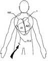
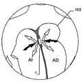
종래 기술로서 전술한 공보들에 개시된 모든 이식형 장치는, 특히 막 부재가 제공되는 경우에 결손구를 보다 양호하게 폐쇄할 수 있거나 또는 보다 적은 정도로 폐쇄할 수 있음을 제공한다. 하지만, 종래 기술의 모든 이식형 장치는 각각이 이식 위치에서 그 전개를 가능하게 하는 충분한 공간이 있는 경우에만 적절하게 사용될 수 있음을 유의해야 한다. 하지만, 정확하게 심장의 좌심방 영역에서는 이식형 장치의 전개 또는 이식을 가능하게 하기 위한 매우 제한된 공간만이 있을 뿐이다.All implantable devices disclosed in the above-mentioned publications as prior art provide that the defect can be better closed or closed to a lesser extent, especially if a membrane member is provided. It should be noted, however, that all implantable devices of the prior art can be suitably used only if each has sufficient space to enable its deployment in the implantation location. However, precisely in the left atrium area of the heart there is only a very limited space for enabling the deployment or implantation of the implantable device.
그러므로, 본 발명의 목적은, 청구항 1에 상술된 바와 같이, 예를 들어 심장의 좌심방에서와 같이 이식 진행을 가능하게 하는 매우 작은 양의 공간만이 있는 경우에서, 인체 및/또는 동물체에 위치에서 이식을 적절하게 하는 방식으로, 하지만, 이식형 장치는 이식 진행 후에 불필요한 변위에 관한 특히 우수한 안정성을 가지도록 이식형 장치를 발전시키는 것이고, 이식형 장치를 전개하는 방법을 제공하는 것이다.It is, therefore, an object of the present invention to provide a method and apparatus for determining the position of a subject in a human body and / or an animal, such as in the left atrium of a heart, as described in
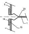
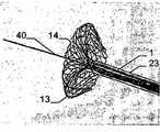
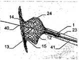
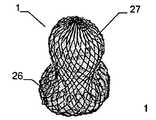
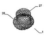
그 목적은 제 2 형태에서 하나 이상의 부분은, 적어도 이중층 구성을 형성하기 위해, 다른 부분의 반대편을 향하여 있는 제 1 서브부, 먼저 제 1 형태로부터 제 2 형태로 전개하고 제 1 서브부 상의 다른 부를 향하는 방향으로 되접혀지는(folded back) 제 2 서브부를 가진다는 점에서 청구항 1에 상술된 바와 같은 이식형 장치에 의해 달성된다.The object is that, in the second aspect, at least one part is a first sub-part facing away from the other part to form at least a bilayer configuration, a first sub-part firstly developed from the first form to the second form, and another part on the first sub- And has a second sub-section folded back in a direction facing away from the first sub-section.
그 목적은 제 1 형태로부터 제 2 형태로 이식형 장치를 전개하는 방법으로도 달성되며, 그 방법은 a)이식형 장치가 카테터 내에서 장형의 제 1 형태로 배치되고, b)이식형 장치가 길이 대 폭의 비율이 작은 제 2 형태로 전개하기 위해 카테터로부터 밀어내어지고, c)카테터로부터 먼저 밀어내어지는, 이식형 장치의 제 1 부분의 서브부는 전개되고, 이식형 장치의 부분의 그것에 인접한 다른 서브부가 카테터로부터 밀어내어지는 경우에 카테터를 향하는 방향으로 후방으로 접혀지고 및 d)카테터로부터 더욱 밀어내어지면서 이식형 장치는 완전히 전개된다. 본 발명의 또 다른 발전은 종속항에서 정의된다.The object is also achieved by a method of deploying an implantable device from a first form to a second form, the method comprising the steps of: a) placing the implantable device in a first, elongated form in the catheter; b) The sub-portion of the first portion of the implantable device, which is pushed out of the catheter for deployment in a second form with a small length-to-width ratio, and pushed out first from the catheter, is deployed, The implantable device is fully deployed as the other sub portion is pushed out of the catheter, folded back in the direction toward the catheter, and d) further pushed out of the catheter. Further developments of the invention are defined in the dependent claims.
따라서, 이식 위치에서 대응하는 카테터로부터 밀어내어지는 경우와 같이, 이식을 위한 오직 작은 공간만을 요구하는 이식형 장치를 제공하고, 이는 일반적으로 카테터로부터 원위로 조금씩 밀어내어지고, 먼저 밀어내어진 서브부가 근위 방향으로 접혀지고, 이식형 장치가 카테터로부터 더욱 밀어내어지는 경우, 카테터에 인접하고 두 번째로 밀어내어지고 원위에서 마주하는, 원위부의 서브부가 전개된다. 이식형 장치가 카테터로부터 더욱 밀어내어지는 경우, 먼저 밀어내어진 서브부가 다른 서브부 상으로 후방으로 접혀지게 되어, 이것이 서로에게 접힌 두 개의 서브부를 위한 이중층 구성에 기여한다. 이중층 구성은 종래 기술에서 단일층 장치에 관하여 현저하게 강화된 이식형 장치의 부분을 제공하여, 이것이 이식 위치에서 특별하게 안전한 자리에 기여한다. 또한, 적어도 이중층 구성은 종래의 상태의 장치와 비교했을 때, 전개시에 이식형 장치의 전체 직경은 직접 전개되고 그 결과 특히 폐쇄될 큰 개구라도 개구를 통하여 장치가 미끄러질 위험 없이 장치가 전체로서 전개되지 않은 조건인 경우에도 항상 폐쇄될 수 있는 것과 같이, 전개상에 유리한 점도 발견된다.Thus, an implantable device that requires only a small space for implantation, such as being pushed out of the corresponding catheter at the implantation site, is provided, which is generally pushed down slightly over the circle from the catheter, When the implantable device is further pushed out of the catheter, a distal sub-portion is deployed adjacent to the catheter and pushed for a second time and facing on the circle. When the implantable device is further pushed out of the catheter, the first pushed out sub-portion is folded back onto the other sub-portion, which contributes to a bilayer configuration for the two sub-folded sub-portions. The bilayer configuration provides a portion of the implantable device that is significantly enhanced with respect to the single layer device in the prior art, which contributes to a particularly secure site in the implantation site. In addition, at least the dual layer construction has the advantage that the overall diameter of the implantable device is directly developed upon deployment and, as a result, even if the opening is large enough to be closed, the device can be deployed as a whole without the risk of the device slipping through the opening It can be always closed even in the case where the conditions are not satisfied.
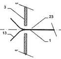
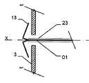
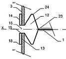
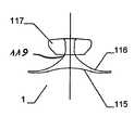
이식형 장치가 결손구 내에, 예를 들어, 심장의 벽체 내에 배치되는 경우, 근위부 및 원위부 사이에 유리하게 제공되고, 근위부 및 원위부에 관하여 감소된 직경의 중간부는 벽체 또는 결손구를 통과하여, 이식형 장치가 결손구 또는 벽체로부터 근접하게 카테터로부터 더욱 밀어내어지는 경우, 이식형 장치의 근위부는 전개된다.The implantable device is advantageously provided within the defect, e.g., within the wall of the heart, between the proximal and distal portions, with the intermediate portion of the reduced diameter relative to the proximal and distal portions passing through the wall or defect, When the shaped device is further pushed out of the catheter proximate the defect or wall, the proximal portion of the implantable device is deployed.
일 부분의 두 개의 서브부에 의하여, 특히, 서로 되접혀지고 서로에 대해 접혀져 있는 원위부는, 이식형 장치가 카테터로부터 밀어내어지는 경우 오직 작은 양의 공간이 원위로 요구되고, 이는 본 발명에 따른 이식형 장치를 예를 들어 심장의 좌심방에 이식을 위한 적절하고 정확하게 한다.The distal portion, particularly folded back against each other, by two sub-portions of the one portion is required on the circle only a small amount of space when the implantable device is pushed out of the catheter, The implantable device is suitably and accurately positioned, for example, for implantation in the left atrium of the heart.
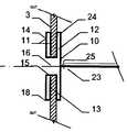
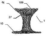
특히 근위부에서, 적어도 일 부분은, 그 엣지 영역이 실질적으로 디스크 형태 또는 볼록한 볼록 구성이 유리하다. 원칙적으로, 양쪽 부분은 유사한 구성이 될 수 있다. 게다가 일 부분은 디스크 형태이고 다른 부분은 부풀어오른 볼록 구성일 수 있다. 바람직하게는, 일 부분은 실질적으로 폐쇄된 말단을 가지는 캐리어 구조체를 가진다. 특히, 캐리어 구조체는 이식형 장치에 대하여 외측에 배치되고 결합되는 근위 단부를 근위로 형성한다. 실질적으로 폐쇄된 말단은 슬리브 부재 내에 수용되고 캐리어 구조체의 웨프트 및/또는 메쉬 및/또는 층상 구조의 직물 및/또는 거즈 말단을 결합시키는 말단의 형태가 될 수 있다. 기타 다른 방법으로 결합될 수도 있다.Particularly in the proximal portion, at least one portion is advantageous in that the edge region has a substantially disc-shaped or convex convex configuration. In principle, both parts can be of similar construction. In addition, one portion may be a disk shape and the other portion may be a convex convex configuration. Preferably, a portion has a carrier structure having a substantially closed end. In particular, the carrier structure is proximal to the proximal end that is disposed and bonded to the implantable device. The substantially closed end may be in the form of a sleeve received within the sleeve member and engaging the weft and / or mesh and / or layered structure of the carrier structure and / or the gauze end. Or may be combined in other ways.
이식형 장치는 이중층 배치로 서로에 대해 접혀지는 말단부가 있는 스텐트 형태로 될 수도 있다. 바람직하게는, 이 경우 제 2 서브부가 제 1 서브부 상에 내측으로 서로 접혀진다.The implantable device may be in the form of a stent with a distal end folded against each other in a bilayer configuration. Preferably, in this case the second sub-part is folded inwardly on the first sub-part.
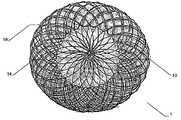
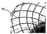
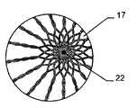
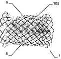
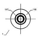
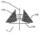
인체 및/또는 동물체에서 결손구, 공동, 기관로 등을 폐쇄 또는 일부 폐쇄하기 위해 사용되는 이식형 장치에 있어서, 제 1 형태로부터 제 2 형태로 재현 가능하게 변환될 수 있는 캐리어 구조체를 포함하되, 상기 캐리어 구조체는 근위부 및 원위부를 가지고 웨프트 및/또는 메쉬 및/또는 층상 구조의 직물 및/또는 거즈 방식으로 형성되고, 일 부분은 바깥을 향하여 개방된 형태이고, 다른 부분은 볼록한 구성에서 폐쇄되고 특히 슬리브 부재에 의해 폐쇄되는 형태이고, 개방된 형태가 제공되는 부분은 이중층 구성으로 서로에 대해 접혀져 있는 적어도 두 개의 서브부를 가진다.An implantable device used to close or partially close a defect sphere, cavity, organs, etc., in a human and / or animal, comprising a carrier structure that can be reproducibly converted from a first form to a second form, Wherein the carrier structure is formed in a weft and / or mesh and / or layered fabric and / or gauze manner with a proximal and a distal portion, one portion is open outwardly and the other portion is closed in a convex configuration In particular closed by a sleeve member, and the portion provided with an open configuration has at least two sub-portions folded against each other in a bilayer configuration.
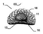
만약 이식형 장치의 근위부가 실질적으로 디스크 형태 구성이라면, 특히 예를 들어 이식형 장치가 배치되는 예를 들어 결손구 주위의 벽체에 양호하게 적용될 수 있다. 근위부에 대하여 볼록한 또는 볼록부 구성은, 다소 만곡된 이식 위치에서 이식형 장치가 배치되는 경우 근위 방향으로부터 이식 위치에서 이식형 장치를 위한 매우 양호하고 정확하게 유지를 보증할 수도 있다. 이러한 볼록한 구성이 제공되는 경우, 바람직하게는 이식형 장치의 근위 말단은 함께 유지되어, 이에 따라 이식형 장치를 통하여 제공될 수 있는 관통 개구가 가능한 작게 유지될 수 있다. 이는 개구용 폐쇄 수단을 형성할 수 있다. 원칙적으로, 여기에서는 이식형 장치를 통하여 고의로 관통 개구를 제공하는 것이 제공하는 것도 가능하다. 만약, 폐쇄 효과를 원한다면, 예를 들어, 이식형 장치의 상술된 추가적인 슬리브 부재가, 결합되는 근위 말단에 맞추어질 수 있다,If the proximal portion of the implantable device is substantially a disc-shaped configuration, it can be particularly well applied, for example, to a wall around the defect, for example, where the implantable device is deployed, for example. A convex or convex configuration with respect to the proximal portion may ensure a very good and accurate retention for the implantable device at the implantation site from the proximal direction when the implantable device is deployed at the somewhat curved implantation site. If such a convex configuration is provided, the proximal end of the implantable device is preferably held together so that the through-hole, which can be provided through the implantable device, can be kept as small as possible. This can form a closing means for the opening. In principle, it is also possible here to provide deliberate penetrating opening through the implantable device. If a closure effect is desired, for example, the above-mentioned additional sleeve member of the implantable device can be fitted to the proximal end to which it is coupled,
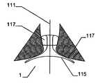
서로 되접혀지게 되는 이중층 구성을 제공함으로써, 원위부에서 특히 우수한 안정성을 실현하는 것이 가능하여, 특히 이식 위치에서 이식형 장치의 안정적인 유지가 가능하다. 이식형 장치의 전개는, 특히 예를 들어, 소위 코브라 효과(cobra effect)가 발생할 수 있는 것과 같이 용이하게 근위로 접근 가능하지 않는, 원위 영역에서 특히 결정적으로 정확할 수 있으며, 그리고 그곳에서는 이식부가 적절하게 전개하지 않지만 함께 접혀지는 조건은 코브라의 머리와 같은 한쪽 측에서 구부러진다. 여기에서는 이식형 장치가 신뢰성있게 원하는 형상으로 전개하는 것이 가장 중요하다. 예를 들어 결손구를 통하여 근위 방향으로부터만 접근 능력이 확보됨에 따라 많은 상황에서 이식 위치의 원위측에서의 조정이 어려워진다. 따라서, 서로에 대해 접혀지고, 특히 우수한 안정성을 부여하는 원위부의 서브부를 제공함으로써 원위측 상에 이식형 장치 부분 강화라는 점에서 특히 바람직하다는 점이 증명되고, 이식형 장치가 적절한 방법으로 원위로 전개한다는 점을 증명한다.By providing a bi-layer construction that is folded back to each other, it is possible to achieve particularly good stability at the distal end, which makes it possible to maintain a stable implantable device, especially at the implantation site. The deployment of implantable devices can be particularly accurate in the distal region, particularly where, for example, the so-called cobra effect is not easily accessible proximal, such as may occur, But the folded condition is bent on one side like the head of the cobra. Here it is most important that the implantable device deploys reliably in the desired shape. For example, as accessibility is secured only from the proximal direction through the defect, adjustment in the distal side of the implant site becomes difficult in many situations. It has therefore been demonstrated that it is particularly desirable in terms of implantable device part reinforcement on the distal side by providing a distal sub-fold that is folded against each other, particularly providing excellent stability, and that the implantable device deploys on the circle in an appropriate manner Prove point.
원위부의 이중층 구성은 예를 들어 결손구와 같은 이식 위치를 둘러싸는 엣지에서 이식형 장치를 안정화하고, 이에 따라 이식 위치에서 이식형 장치의 고정 및 이동을 돕는다. 근위부를 향하는 방향으로 되접히는 원위부의 제 2 서브부는 보다 짧은 전개 길이가 요구됨에 따라 주변으로 연장하는 얇은 엣지의 형상에서 좁은 것이 바람직하며, 그 결과 이식형 장치의 전개시 요구되는 공간이 보다 작다. 대안적으로 또는 추가적인 부분으로서, 근위부를 향하는 방향으로 접혀지게 되는 원위부의 제 2 서브부는, 근위부와 원위부 사이의 중간부에 연장할 수 있거나 또는 폐쇄할 수 있다. 특히 오히려 지탱하러 올 수 있다. 이러한 배치에 의하여, 원위부의 이중층 구성에 의하여, 원위부의 서브부를 원위로 마주하는 전체 범위에 거쳐서 안정화가 가능하다. 게다가, 예를 들어 인간 또는 동물의 심장 벽체를 지탱하는 제 2 서브부는 약간 만곡되어 있는 전체 원위부 또는 아치형의 구성 또는 하나 이상의 서브부 중 하나에 의해, 미리 결정 가능한 또는 미리 결정된 공간에서 다른 것 상에 배치되는 원위부의 다른 서브부와 관련하여, 오히려 탄력적으로 지탱할 수 있어, 이식 위치에서 특히 안정적인 맞춤을 가능하게 하는 탄성 액션이 생성될 수 있다.The dual layer configuration of the distal portion stabilizes the implantable device at the edge surrounding the implant location, e.g., a defect, thereby assisting in the fixation and movement of the implantable device at the implantation site. The distal second sub-portion, which is folded back in the direction toward the proximal portion, is preferably narrow in the shape of a thin edge extending to the periphery as a shorter deployment length is required, resulting in less space required in deploying the implantable device. Alternatively, or as a further portion, the second sub-portion of the distal portion that is folded in the direction toward the proximal portion may extend or close in the middle between the proximal portion and the distal portion. In particular, it can come to bear. With this arrangement, the dual layer configuration of the distal portion allows stabilization over the entire range of the distal portion of the sub-portion facing the circle. In addition, the second sub-part, for example supporting the heart wall of a human or animal, can be placed in a predeterminable or predetermined space on another, by one of the entire distal or arcuate configurations or one or more sub- With respect to the other subdivisions of the distal part to be deployed, it can rather be supported elastically, so that a resilient action can be created which allows a particularly stable fit at the implantation site.
바람직하게는, 근위부와 원위부 사이에 제공되고 근위부 및 원위부에 대하여 감소된 직경의 중간부의 직경 및/또는 이식형 장치를 통하여 연장하는 관통 개구의 직경은, 인체 및/또는 동물체의 벽체, 기관, 동공 사이에 명확한 연통구를 제공하기 위해 미리 결정 가능한 방법으로 크기가 결정된다. 그러므로 이식형 장치를 통하는 관통 개구 또는 이식형 장치의 근위부와 원위부 사이의 중간부는 이러한 사이즈가 될 수 있어, 인체 또는 동물체의 내에 두 개의 챔버, 동공, 벽체, 기관 등 사이에 원하는 명확한 연통구가 제공될 수 있다.Preferably, the diameter of the intermediate portion of the reduced diameter provided between the proximal portion and the distal portion and / or of the reduced diameter relative to the proximal and distal portions and / or the diameter of the penetrating opening extending through the implantable device is greater than the diameter of the body, The size is determined in a predetermined manner so as to provide a clear communication hole therebetween. Thus, the through-opening through the implantable device or the intermediate portion between the proximal and distal portions of the implantable device can be of such a size that a desired clear communication opening is provided between the two chambers, pupils, walls, .
바람직하게, 이식형 장치의 원위부는 그 근위부와는 독립적으로 전개할 수 있다. 특히 원위부는 근위부와는 독립적이고 완전하게 전개할 수 있다. 이는, 예를 들어 인간 또는 동물의 심장에서 큰 결손의 영역에 이식형 장치를 배치하는 경우 심장의 우측으로 빈번하게 풀리기에 종래 기술에서 불가능하였던 비교적 큰 결손의 폐쇄를 가능하게 한다.Preferably, the distal portion of the implantable device is deployable independently of its proximal portion. In particular, the distal portion is independent of the proximal portion and can be fully deployed. This allows for the closure of relatively large defects which have not been possible in the prior art, for example, frequently to the right of the heart when placing the implantable device in the area of a large defect in the human or animal heart.
하나 이상의 막 부재는 근위 영역 및/또는 원위부 및/또는 근위부 또는 원위부 사이에 제공될 수 있다. 막 부재는 적당한 방법, 예를 들어 그곳에 접착 또는 봉합됨으로써 또는 기타 다른 방법으로 이식형 장치의 캐리어 구조체의 웨프트, 메쉬, 층상 구조의 직물 또는 거즈에 고정될 수 있다. 유리하게는, 막 부재와 캐리어 구조체 사이의 고정은 캐리어 구조체의 외부 엣지 영역에서 봉합(sewing)에 의해 제공된다. 캐리어 구조체에 대한 막 부재의 고정은 막 부재의 엣지 주위에 실형 부재를 통과시키고 캐리어 구조체의 엣지 측 둘레에 그것을 고리화(looping)하고 캐리어 구조체의 엣지 루프에서 하나 이상의 매듭(knotting)을 제공함으로써 제공된다. 엣지에서 막 부재와 캐리어 구조체를 봉합하는 것은 양호하고 확실한 고정을 제공할 뿐만 아니라 후에 미끄러지는 위험 없이, 기타의 문제없이 막 부재에 의해 캐리어 구조체가 완전히 덮이는 것을 제공한다. 바람직하게는 막 부재는 순수한 메쉬의 형태가 될 수 있어 막 부재의 개별적인 실이 함께 연결되고 실의 변위를 방지한다. 이러한 막 부재의 구성은 상피 조직(epithelium) 형성이 촉진되고 혈전증(thrombosis) 형성이 방지될 수 있다는 의미가 있다. 하나 이상의 막 부재는 삽입되거나 또는 다중층 조건에서 배치되고 캐리어 구조체에 의해 형성되는 다리부 사이에 삽입 가능할 수 있다. 다리부는 이식형 장치의 중심 영역에 배치될 수 있어, 막 부재가 어떠한 문제 없이 그 사이에 삽입될 수 있다.One or more membrane members may be provided between the proximal region and / or the distal portion and / or the proximal or distal portion. The membrane member may be secured to the weft, mesh, layered fabric or gauze of the carrier structure of the implantable device by an appropriate method, e. G. By gluing or sealing thereon or by any other means. Advantageously, fixation between the membrane member and the carrier structure is provided by sewing in the outer edge region of the carrier structure. Fixation of the membrane member to the carrier structure is provided by passing the sealing member around the edge of the membrane member and looping it around the edge side of the carrier structure and providing one or more knots in the edge loop of the carrier structure do. Suturing the membrane member and the carrier structure at the edge not only provides good and reliable fixation but also provides for the carrier structure to be completely covered by the membrane member without any risk of slipping back. Preferably, the membrane members may be in the form of a pure mesh so that the individual chambers of the membrane members are connected together and prevent displacement of the seal. The construction of such a membrane member means that the formation of epithelium is promoted and the formation of thrombosis can be prevented. One or more membrane members may be inserted or interposed between the legs that are disposed in multi-layered conditions and formed by the carrier structure. The legs can be placed in the central region of the implantable device, so that the membrane member can be inserted therebetween without any problems.
또한, 바람직하게는, 만약 막 부재의 직경이 폐쇄될 결손구에 거의 대응한다면, 또 다른 유리한 점을 찾을 수 있다. 예를 들어, 원위부의 두 개의 서브부와 함께 근위부를 향하는 방향으로 후방으로 지향되는 적어도 이중층 구성에 의하여, 막 부재가 결손구의 영역의 심장의 좌측을 완벽히 덮는 방식으로 이식형 장치에 고정되는 것이 가능하다. 대조적으로 막 부재로서 이식형 장치용의 니티놀 및 폴리에스테르의 조합을 사용하는 종래 기술에서 색전증을 야기하는 이식형 장치의 캐리어 구조체의 메쉬에서 형성할 수 있는 응혈(clots)의 위험은 이 경우 최소화된다. 이 경우, 결손구를 둘러싸는 벽체의 영역에서 서로에 대한 폴리에스테르 및 니티놀 지탱하고, 그 결과로서 예를 들어 두통 또는 일시적으로 안 보이는 경우와 같이 전문 저널에 개시되는 사건을 이끄는 응혈 형성을 이끌 수 있다. 바람직하게는 본 발명에 따른 이식형 장치를 사용하는 경우, 본 발명에 따른 막 부재가 결손구에 대응하는 것과 같은 크기라는 가능성에 의하여, 이들 사건은 더 이상 발생하지 않을 것이다.Also advantageously, another advantage can be found if the diameter of the membrane member corresponds substantially to a defect orifice to be closed. For example, with at least a bilayer configuration that is directed backward in a proximal direction with two subdivisions of the distal portion, it is possible for the membrane member to be secured to the implantable device in such a way that it completely covers the left side of the heart of the region of the deficient sphere Do. In contrast, the risk of clots that can form in the mesh of the carrier structure of an implantable device causing embolism in the prior art using a combination of nitinol and polyester for implantable devices as membrane members is minimized in this case . In this case, it may be possible to lead to clot formation leading to the events described in the professional journals, such as those with polyester and nitinol on each other in the area of the wall surrounding the defect, resulting in, for example, have. Preferably, with the use of an implantable device according to the invention, these events will no longer occur due to the possibility that the membrane members according to the invention are the same size as corresponding to the defect sites.
또한, 이식형 장치의 제 2 형태의 막 부재가 폐쇄될 결손구의 직경을 거의 가정하는 방식으로 이식형 장치에 막 부재가 고정될 수 있다는 점이 유리하다. 이러한 방식에서, 폐쇄될 결손구 또는 폐쇄될 각각 홀과 같이 동일한 크기를 정확히 가정하는 방식으로 막 부재가 이식형 장치에 정확하게 고정되는 것이 가능하다. 이것은 바람직하게 가능한 작은 크기이고 응혈 위험이 감소되기 때문에 정확한 막 부재를 사용하는 것을 가능하게 한다. 이러한 방식으로 인간 또는 동물의 심장 벽체의, 결손구를 둘러싸는 엣지는 막 부재가 있는 메쉬 또는 거즈의 조합에 의하지 않고 이식형 장치의 캐리어 구조체의 메쉬 또는 거즈에 의해 배타적으로 둘러싸이고, 이로 인해 응혈 위험이 상당히 감소될 수 있다.It is also advantageous that the membrane member can be secured to the implantable device in such a way that the membrane member of the second form of the implantable device is substantially assumed to have a diameter of the defect orifice to be closed. In this way, it is possible for the membrane member to be precisely secured to the implantable device in a manner that precisely assumes the same size, such as a defect to be closed or a respective hole to be closed. This makes it possible to use the precise membrane member because it is preferably as small in size as possible and the risk of clotting is reduced. In this way, the edges of the heart wall of a human or animal heart, which surround the defect, are exclusively surrounded by the mesh or gauze of the carrier structure of the implantable device, without the combination of mesh or gauze with a membrane member, The risk can be significantly reduced.
상술된 바와 같이, 막 부재가 이러한 크기이고 이식형 장치의 제 2 형태에서 이식형 장치에 고정된다면, 막 부재가 실질적으로 그것을 완전히 덮고 특히 실질적으로 원위부 전체를 완전히 덮는다는 유리한 점이 발견된다. 감소된 응혈의 위험은 여기에서 유리한 효과로서 발견된다. 이는 인간 또는 동물의 뇌에 혈액이 흘러 응혈이 위협적인 결과를 가질 수 있다는 점에서부터 심장의 좌측에 특히 유리하다는 점이 증명된다. 혈액이 인간 또는 동물의 심장의 우측으로부터 응혈이 필터링되고 용해되는 폐로 흘러 응혈이 거기에서 이러한 반대의 결과를 가지지 않는다.As noted above, the advantage is found that if the membrane member is of such a size and secured to the implantable device in the second form of implantable device, the membrane member substantially completely covers it and in particular completely covers the entire distal portion. The risk of reduced clotting is found here as a beneficial effect. This proves to be particularly beneficial to the left side of the heart from the point that blood can flow into the human or animal brain and clotting can have a threatening consequence. The blood flows from the right side of the human or animal heart to the lungs where the clot is filtered and dissolved and there is no such opposite result.
이식형 장치에서 복수의 막 부재가 사용될 수도 있고, 그리고 이는 폐쇄될 개구 내의 이식형 장치에 관하여 폐쇄 옵션의 두드러지는 향상을 이끈다는 점이 높이 평가될 것이다. 게다가, 이식형 장치의 캐리어 구조체의 구조 구성(거즈, 층상 구조의 직물, 메쉬, 웨프트 등)은 치밀하여(dense) 더 이상 막 부재가 요구되지 않고, 캐리어 구조체 그 자체로 이러한 막 부재의 기능을 취한다. 이 경우, 이식형 장치의 캐리어 구조체의 구조 구성이 치밀하여 캐리어 구조체는 막 부재로서 행동한다.It will be appreciated that a plurality of membrane members may be used in an implantable device, which leads to a noticeable improvement in the occlusion option with respect to the implantable device in the opening to be closed. In addition, the structural configuration (gauze, layered fabric, mesh, weft, etc.) of the carrier structure of the implantable device is dense and no further membrane members are required and the carrier structure itself Lt; / RTI > In this case, the structural structure of the carrier structure of the implantable device is dense, so that the carrier structure acts as a membrane member.
이식형 장치의 캐리어 구조체는 예를 들어 형상 기억 재료, 특히 금속 또는 금속 합금, 특히 니티놀, 또는 플라스틱 재료를 포함할 수 있다. 이러한 것이 제공되는 막 부재는 플라스틱 재료, 특히 폴리에스테르 또는 또 다른 중합체(polymer)를 포함할 수 있다. 이식형 장치의 캐리어 구조체는 단일의 와이어형 부재로부터 형성되는 것이 바람직하다. 하지만, 이것은 복수의 와이어형 부재로부터 형성될 수 있다. 캐리어 구조체에 관하여서는 단일의, 2겹의, 또는 2겹의 감긴(wound), 3중의, 3중의 땋여진(braided), 와이어형 부재, 특히 니티놀 와이어, 또는 다중의 감긴, 트위스트 또는 땋여진 와이어형 부재, 특히 니티놀 와이어로부터 형성될 수 있다. 또한, 상술한 변형들의 조합을 제공하는 것도 가능하다. 이러한 이식형 장치의 구성에 있어서, 카테터로부터 밀어내어진 이식형 장치는 상기 전술한 그리고 큰 이식형 장치를 다루는 경우에, 그것들을 형성하는 구조에 관한 상이한 구성의 종래 기술에서의 경우에는 주요한 문제를 이끄는 코브라 형상을 나타내지 않다는 점에서 유리하다는 점이 증명된다. 이식형 장치의 캐리어 구조체는 섬유, 특히 중합체 섬유를 통하여 짜여질 수 있다. 이는 스텐트 형태의 이식형 장치의 경우에서 특히 유리하게 사용될 수 있고 별도의 막 부재를 대체할 수 있는 치밀한 캐리어 구조체를 제공한다.The carrier structure of the implantable device may comprise, for example, a shape memory material, in particular a metal or metal alloy, especially nitinol, or a plastic material. The membrane member to which this is provided may comprise a plastic material, in particular a polyester or another polymer. The carrier structure of the implantable device is preferably formed from a single wire-like member. However, it can be formed from a plurality of wire-like members. With respect to the carrier structure, a single, double, or double strand wound, triple, triple braided, wire-like member, especially a nitinol wire, or multiple wound, twisted or braided wires Shaped member, particularly a ninitil wire. It is also possible to provide a combination of the above variations. In the construction of such an implantable device, the implantable devices extruded from the catheter have a major problem in the case of the above-described and large implantable devices, in the case of the prior art of different configurations for the structures forming them It is advantageous in that it does not exhibit a cobra shape leading to the cobra. The carrier structure of the implantable device can be woven through fibers, in particular polymer fibers. This provides a dense carrier structure that can be used particularly advantageously in the case of an implantable device in the form of a stent and can replace a separate membrane member.
이식형 장치의 캐리어 구조체(거즈, 메쉬, 웨프트, 층상 구조의 직물 등)을 감당할 수 있는 하나의 단일의 와이어형 부재만의 사용은 개개의 와이어형 부재 사이에 접합 위치와 같이 용접 또는 납땜 위치가 제공될 필요가 없고, 이러한 접합 위치에서 발생할 수 있는 파손의 두려움이 없고 어떤 부식의 위험도 없다는 결과를 갖는다는 것을 의미한다. 이러한 부식 및 접합 위치는 다른 점에서 이식형 장치의 파손 심지어 환자에 대한 상해 또는 이식 후의 사건 또는 이식 진행 동안에도 파손의 경우를 야기한다. 종래 기술에 있어서 마주치던 이러한 문제는 더 이상 본 발명에 따른 이식형 장치에 있어서 발생하지 않는다.The use of only a single wire-like member capable of supporting a carrier structure (gauze, mesh, weft, layered fabric, etc.) of the implantable device allows the use of only a single wire- Does not need to be provided and there is no fear of breakage that may occur at such a joint position and there is no risk of any corrosion. Such corrosion and joint locations cause damage to the implantable device, or even injury to the patient or event after implantation or even during implantation, in other respects. This problem encountered in the prior art no longer occurs in the implantable device according to the present invention.
하나 이상의 와이어형 부재는 둥근 또는 평평한 단면 또는 평평한 및 둥근 단면 형상의 여타의 조합으로 될 수 있다. 게다가, 이식형 장치의 캐리어 구조체는 말단에 하나 이상의 루프 또는 아이(eye)를 제공할 수 있다. 캐리어 구조체의 잔류부의 방향으로의 루프 또는 아이는 트위스트된(twisted) 또는 섞여 짜여진 부분으로 들어갈 수 있어, 더 나은 안정도는 덜 치밀한 메쉬 또는 거즈의 준비와 동시에 부분적으로 달성될 수 있다. 하나의 와이어형 부재의 말단은 캐리어 구조체의 표면에서 함께 짜여지는 것이 바람직하다. 이러한 배치에 의하여, 이러한 배치를 제공함으로써, 와이어가 말단에서 캐리어 구조체로부터 돌출되는 이식 위치를 둘러싸는 혈관 또는 조직을 다치게 할지 못한다.The one or more wire-like members may be round or flat cross-sections or any other combination of flat and round cross-sectional shapes. In addition, the carrier structure of the implantable device may provide one or more loops or eyes at the distal end. A loop or eye in the direction of the remaining portion of the carrier structure may enter the twisted or interwoven portion so that better stability can be achieved partially at the same time as preparation of the less dense mesh or gauze. It is preferable that the ends of one wire-like member are woven together at the surface of the carrier structure. By such an arrangement, by providing such an arrangement, it does not hurt the blood vessels or tissues surrounding the implantation site where the wire protrudes from the carrier structure at the distal end.
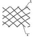
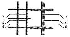
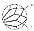
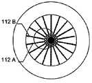
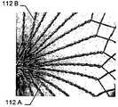
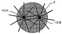
유리하게는, 이식형 장치의 캐리어 구조체는, 서로 짜여진 또는 땋여진 트위스트된 와이어형 부재, 또는 함께 트위스트된, 교차점에서 개별적으로 또는 서로 트위스트된 부재의 형상으로서 땋여지는 와이어형 부재의 부분을 포함한다. 이러한 것으로서 이식형 장치의 캐리어 구조체는 짜여진 또는 함께 땋여진 하나 이상의 와이어형 부재를 포함할 수 있고, 와이어형 부재의 일부는 함께 트위스트될 수 있어 그것들은 한 쌍의 부재로 정의될 수 있다. 함께 트위스트된 와이어 형의 한 쌍의 부재가 제공되는 경우, 개개의 와이어형 부재는 교차점에서 서로 개별적으로 각각 땋여질 수 있고, 전체 한 쌍의 부재는 다른 한 쌍과 함께 땋여질 수 있다. 후자의 변형에 있어서, 함께 트위스트된 두 개의 와이어형 부재, 또는 와이어형 부재의 두 부분은 또 다른 부재 쌍을 둘러싼다. 이와 유사한 방법으로, 와이어형 부재나 와이어형 부재의 부분 중 두꺼운 가닥 역시 함께 땋아질 수 있다. 와이어형 부재 또는 와이어형 부재의 부분을 트위스팅하는 것은 한층 높은 레벨의 안정성을 확보할 수 있다는 것을 의미하며, 동시에 명시된 방법으로 트위스트된 부재 쌍을 땋는 것은, 이식형 장치상 한 쪽으로 치우친 긴장으로 인하여 상이한 크기의 개구들이 비의도적으로 생길 수 없도록 캐리어 구조체 내의 각각의 부재 쌍의 위치가 안전하게 확보되는 것을 의미한다.Advantageously, the carrier structure of the implantable device comprises a portion of a wire-like member that is woven or braided twisted together, or braided together in the form of a twisted, twisted, do. As such, the carrier structure of the implantable device may include one or more wired members that are woven or braided together, and some of the wired members may be twisted together so that they can be defined as a pair of members. When a pair of wire-type members twisted together are provided, the individual wire-like members may be individually braided to each other at an intersection, and the entire pair of members may be braided together with another pair. In the latter variant, the two wire-like members twisted together, or two parts of the wire-like member, surround another pair of members. In a similar manner, the thick strands of the portions of the wire-like member or of the wire-like member may also be braided together. The twisting of a part of a wire-like member or a wire-like member means that a higher level of stability can be ensured, and at the same time braiding a pair of twisted members in a specified manner is advantageous because of the biased tension on the implantable device This means that the position of each pair of members in the carrier structure is securely secured such that openings of different sizes can not unintentionally occur.
상기 캐리어 구조체는 단일층, 다중층, 또는 다중층 구성에서 하나 이상의 와이어형 부재로 이루어질 수 있다. 이것은 캐리어 구조체의 안정성뿐만 아니라, 자연스럽게 캐리어 구조체의 밀도에 영향을 줄 수 있으며, 따라서 결손구가 막 부재가 없더라도 폐쇄될 수 있도록 해준다.The carrier structure may consist of one or more wire-like members in a single layer, multi-layer, or multilayer configuration. This not only affects the stability of the carrier structure, but also naturally affects the density of the carrier structure, thus allowing the defect sphere to be closed even without the membrane member.
캐리어 구조체의 지층(stratum)이나 층 각각은 동일한 물질 또는 상이한 물질로 이루어질 수 있다. 한 예로서, 적어도 한 층은 니티놀, 적어도 바로 다음의 층은 폴리에스테르, 그리고 그 다음 층은 PTFE로 구성될 수 있다. 그러한 방법을 통해, 소기의 안정성과 함께, 될 수 있는 한 부분적으로 상이한 레벨의 내구력을 지닌 캐리어 구조체를 생산하는 것이 가능하다. 더욱이, 하나 이상의 막 부재가 적어도 두 층 사이에 배치될 수 있다. 막 부재는 캐리어 구조체의 층들 사이에 안정적으로 견고히 배치될 수 있다. 유리하게도, 막 부재의 재료의 선택은 캐리어 구조체가 배치되는 개개의 막의 재료에 매칭될 수 있다.Each stratum or layer of the carrier structure may be made of the same material or a different material. As an example, at least one layer may be composed of Nitinol, at least the immediately following layer of polyester, and the next layer of PTFE. With such a method, it is possible to produce a carrier structure with a desired level of durability, possibly with the desired stability. Moreover, one or more membrane members may be disposed between at least two layers. The membrane member can be stably and firmly disposed between the layers of the carrier structure. Advantageously, the selection of the material of the membrane member can be matched to the material of the individual membrane on which the carrier structure is disposed.
이식형 장치는 동심 또는 편심 형상이 될 수 있다. 유리하게도 이식형 장치의 캐리어 구조체는 제 2 형태에서 다른 부분을 향하는 방향으로 되접혀진, 하나 이상의 한 부분 내의 서브부를 가지면서, 이식 위치에 관련된 구성에 대해 자동으로 적용된다. 되접혀진 상태에 있는 한 서브부를 가진 이식 장치의 특정 원위부의 특정한 구정은 이식형 장치 또는 이식형 장치의 캐리어 구조체가 고정된 중심을 갖지 않음으로써 이식형 장치가 어떠한 형태의 결손에 대해서도 가요성으로 적용될 수 있게 하거나, 또는 결손에 덧붙여진 제 2차 형태에 대해서 미리 적용될 수 있도록 해준다. 예를 들어 만약 결손구가 타원형 중 하나라면, 이식 장치는 그런 상황에서 결손구에 특히 잘 맞을 수 있는 타원형을 취할 수 있다. 이식장치가 기대어 있는 인접한 벽체에 대한 적용 또한 이식 장치가 되접힌 서브부 의해 이식 부분, 그리고 적어도 이중층 부분(예를 들어, 원위부)에 특히 안정적이고 견고한 받침을 제공한다는 점에서 아무런 문제없이 가능하다. 종종 폐쇄되어야 하는 결손구가 대동맥에 인접하여 위치하기도 한다. 상기 이식 장치는 편리하게도 결손구의 위치와 주변부에 대한 어느 방향으로도, 즉 대동맥 벽체에 대해서, 이식 장치의 상대적 위치에 관해 아무런 문제 없이 적용될 수 있다. 이와 상응하는 방법으로, 이식형 장치는 예를 들어 폐, 심방 중격, 관상 정맥, 폐정맥 그리고 특정 벽체의 판막 엣지를 둘러싼 구조에서의 결손구에서 적용될 수 있다.The implantable device may be concentric or eccentric. Advantageously, the carrier structure of the implantable device is automatically applied to the configuration associated with the implant location, with the sub-part in one or more of the parts folded back in the direction from the second configuration to the other part. The specific orientation of a particular distal portion of a graft device having a sub-fold in its retracted state does not have a fixed center of gravity of the carrier structure of the implantable device or graft device so that the graft device is flexibly applied to any type of defect Or to be applied in advance to the second form attached to the defect. For example, if the defect sphere is one of the ellipses, the implant device may take an elliptical shape which may be particularly well suited to the defect sphere in such a situation. Application to adjacent walls on which the implanted device is leaning is also possible without any problem in that the implanted device provides a particularly stable and robust pedestal at the implanted portion and at least the bilayer portion (e.g., the distal portion) by the folded sub-portion. Often, the defect is located adjacent to the aorta, which should be closed. The implantation device can conveniently be applied to the location of the defect and to the periphery in any direction, i. E. Relative to the aortic wall, relative to the relative position of the implant. In a corresponding manner, the implantable device can be applied, for example, to a defect in the structure surrounding the valve, atrial septum, coronary vein, pulmonary vein and the valve edge of a particular wall.
대안적으로, 이식형 장치는 이식 위치의 상대적인 위치에 대해 적합하도록 변형될 수 있다. 이는 적합하게 미리 형성이 결정되어 특히 미리 구부러지거나 미리 만곡된 원위부나 근위부를 이식형 장치의 제 2 형태에서 이미 제공함으로써, 이식형 장치가 이미 이식 위치에 맞는 형태로 전개될 수 있도록 한다. 이는 특히 이식형 장치가 옆에 배치된 대동맥에 대한 압력을 피할 수 있도록 한다. 그렇지 않으면 대동맥에 대한 이러한 압력이 대동맥에 개구를 뚫을 수 있으며, 환자의 생명을 위협하는 결과를 낳을 수 있다. 이식 위치의 구성에 대해서 이식형 장치의 최적의 적용 형태를 제공하는 가능성과 열처리에 의해 형상 기억 재질로 구성된 캐리어 구조체를 바람직하게 사용할 때 그 형태를 제 2 형태로서 장치에 부여할 수 있는 가능성은, 되접혀지거나 후방으로 접혀진 서브부를 포함하며 결과적으로 부여된 제 2 형태의 구성이 특히 안정적이도록 하는 적어도 이중층 배치인 부분에 의해서 더욱 도움받는다. 이러한 특정 배치가 겪을 수 있는 위험이 이로 인하여 충분히 배제될 수 있다. 폐쇄되어야 할 결손구 부위에서의 최악의 상황에서도 적용될 수 있는 제 2 형태의 구성의 미리 부여하는 가능성이, 대동맥 손상의 위험 때문에 지금까지 치료받을 수 없었던 환자들이 치료받을 수 있도록 해준다. 모든 ASD 환자의 30% 이상의 경우에 있어서, 결손구에 접한 대동맥 벽체나 다른 벽체 또는 구조의 손상 위험이 너무 크기 때문에 지금까지 시중에 유통되는 이식 장치를 사용한 치료는 이행될 수 없다. 현재, 편리하게도 상기 이식 장치의 제 2 형태가 이식 부위의 조건에 맞게 적용될 수 있기 때문에, 결손구에 접한 대동맥 벽체나 다른 벽체 또는 구조에 침입하거나 손상시키는 위험이 더 이상 발생하지 않으며, 따라서 그러한 환자들도 치료받을 수 있다. 일 부분의 이중층 서브부로 인하여, 이식 부위에 대해 적용되는 이식 장치의 상대적 배치를 잃지 않고 변함없이 안정적으로 된다.Alternatively, the implantable device may be modified to suit the relative position of the implantation site. This allows the implantable device to be deployed already in a form that fits the implant location, by appropriately providing the preformed and especially pre-bent or pre-curved distal or proximal portion in a second form of implantable device. This in particular allows the implantable device to avoid pressure on the aorta placed next to it. Otherwise, this pressure on the aorta can puncture the opening in the aorta and result in a patient's life-threatening consequences. The possibility of providing an optimal application form of the implantable device with respect to the configuration of the implantation position and the possibility of imparting the form to the device as the second form when the carrier structure composed of the shape memory material is preferably used by heat treatment, And is further assisted by at least a double layer arrangement which includes a folded back or folded back sub-portion and which consequently ensures that the configuration of the second type provided is particularly stable. The risks that this particular arrangement may suffer can therefore be excluded sufficiently. The possibility of preliminarily giving a second type of configuration, which can be applied even in the worst case conditions at the defect site to be closed, allows patients who have not been treated so far to be treated because of the risk of aortic injury. In the case of more than 30% of all ASD patients, the risk of damage to the aortic wall or other wall or structure in contact with the defect is so great that treatment with a commercially available implantable device can not be performed until now. At present, there is no longer a risk of intrusion or damage to the aortic wall or other wall or structure in contact with the defect, conveniently because the second form of the implant can be applied to the conditions of the implant site, Can also be treated. Due to the double-layer sub-part of the one part, it remains stable without losing the relative placement of the implanted device applied to the implant site.
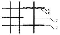
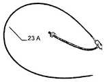
바람직하게는 이식 수술 중 모니터링 장치에서 시각적으로 이식 장치를 보이기 위한 표지로서 하나 이상의 부재가 제공된다. 상기 하나 이상의 부재는 이식 장치의 엣지에 설치된 미세나선(microspiral)일 수 있다. 이러한 미세나선은 이식 장치의 엣지에서 이식 장치를 휘감는 부분으로 될 수 있다. 특히 바람직하게는 하나 이상의 부재가 X-레이 가시 재료, 특히 70~90% 백금과 30~10% 이리듐을 포함한 재료로 구성되어 있다. 또한, 장치가 모니터링 장치로 시각적으로 보여지도록 해주는 그 이외의 재료의 사용도 가능하다는 것이 인지될 것이다. Preferably, one or more members are provided as markers for visually displaying the implanted device in a monitoring device during a graft operation. The at least one member may be a microspiral disposed at an edge of the implant device. Such a fine helix can be a portion that wraps around the implant at the edge of the implant. Particularly preferably, the at least one member is composed of an X-ray visible material, in particular a material comprising 70 to 90% platinum and 30 to 10% iridium. It will also be appreciated that other materials may be used that allow the device to be visually displayed as a monitoring device.
본 발명에 따른 이식 장치의 특정 구성(배치)에 의해, 이식 장치는 MNR 호환성이며, 따라서 이식 수술을 모니터하는 점에 대해 어떠한 문제도 야기하지 않는다. 따라서 예를 들자면 X-레이 조상, 초음파장치(echography), 신티그램(schintigraphy) 등의 이미지화 공정(imaging processes)에 의해 이식 진행 과정 중 이식 장치가 추적될 수 있다. 만약, 종래 기술에서와 같이, 강철 와이어에 용접 부위가 있다면, 이미징 프로세스를 사용할 시 인공물이 보여질 것이고, 이러한 인공물은 이식 진행 과정을 추적하는 데 있어서 문제를 야기한다.Due to the specific configuration (arrangement) of the implantable device according to the invention, the implantable device is MNR compatible and therefore does not cause any problems in monitoring implantation. Thus, implantation devices can be traced during the implantation process by imaging processes such as X-ray ancopy, echography, and schintigraphy. If, as in the prior art, there is a weld on a steel wire, an artifact will be visible when using the imaging process, and this artifact causes problems in tracking the progress of the implant.
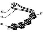
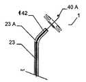
본 발명에 따른 이러한 이식 장치는, 이식 장치가 이식 위치에 대해 적절하게 적용되거나 그곳에 순응하고 안전하게 배치될 수 있는 점에 있어서는, 어떠한 각도에서도 적당한 배출 기기로 결손구에 배치될 수 있다. 이식 위치에서의 이식 각도에 대한 적용을 위해, 이식형 장치는 쉽게 구부려지는 중간부를 제공하며, 특히 곧은 중간부 그리고/또는 콘서티나형(concertina)으로 뒤집히거나 그리고/또는 접혀지는 중간부를 제공한다. 각각에 대해 일체로 섞여 짜여진 이식 장치의 공급이 가능하고, 그 경우 이식 장치의 두 절반부 또는 부분의 접합점이 바람직하게도 중간부에 있어서 어떠한 굴곡도 그 부분에서 가능하다. 본 발명에 따른 배출 기기는 특히 가이드 또는 배출 와이어에 관해 와이어를 지지하는 것에 의한 작동에 의해 이식 장치가 함께 회전할 수 있도록 디자인된다. 바람직하게, 배출 와이어는 약 0.1 ~ 0.3mm 직경의 얇은 선단(tip)을 갖는다. 이식 장치의 캐리어 구조체가 치밀한 메쉬 구조라도, 이는 이식 장치의 캐리어 구조체를 관통하여 쉽게 끼워 넣어질 수 있도록 한다. 배출 와이어가 지지 와이어를 관통하도록 지지 와이어는 하나 이상의 루프를 가지고 있다. 바람직하게, 이식 장치에 고정하도록 유지 와이어는 이식 장치의 캐리어 구조체의 말단 루프를 관통하여 끼워질 수 있다. 이는 이식 과정에서 지지하고 지향할 수 있도록, 이식 장치의 캐리어 구조체 상에 특히 견고한 지지대를 제공할 수 있도록 한다. 대안적으로 또는 부가적으로, 유지 와이어는 이식 장치의 말단 루프를 함께 연결하는 캐리어링(carrier ring)을 관통하여 끼워질 수도 있다.This implantation device according to the invention can be placed in the defect orifice with a suitable drainage device at any angle in that the implantation device can be suitably applied to the implantation site or can be adapted and safely deployed there. For application to the implantation angle at the implantation site, the implantable device provides an intermediate portion that is easily bent and particularly provides an intermediate portion that is inverted and / or folded into a straight middle portion and / or a concertina . It is possible to supply an interwoven device which is interwoven with each other for each, in which case the junctions of the two halves or portions of the implanted device are preferably in the middle, so that any bending is possible in that part. The discharge device according to the invention is designed so that the implanting device can rotate together, in particular by operation by supporting the wire on a guide or discharge wire. Preferably, the discharge wire has a thin tip with a diameter of about 0.1 to 0.3 mm. Even if the carrier structure of the implanted device is a dense mesh structure, it can be easily inserted through the carrier structure of the implanted device. The support wire has one or more loops such that the discharge wire penetrates the support wire. Preferably, the retaining wire may be inserted through the end loops of the carrier structure of the implanted device for securing to the implant device. This makes it possible to provide a particularly rigid support on the carrier structure of the implanted device so that it can be supported and oriented during the implantation process. Alternatively or additionally, the retaining wire may be inserted through a carrier ring connecting the end loops of the implant device together.
바람직하게 이식 장치는 하나 이상의 배출 와이어와 하나 이상의 유지 와이어 주변을 회전하고 부유할 수 있다. 이것은 인체 또는 동물체에서 접근이 어려운 위치라도 정확한 위치잡기(positioning)를 가능하게 한다.Preferably the implanted device can rotate and float around the at least one discharge wire and the at least one holding wire. This allows precise positioning even in difficult-to-reach locations in the human body or the animal.
이러한 배출 기기를 사용하여 인체 또는 동물체 내 이식 위치에 이식형 장치를 배출하는 방법에 있어서, 하나 이상의 유지 와이어는 이식형 장치의 캐리어 구조체의 말단에 배치되는 루프 및/또는 이식형 장치의 캐리어 구조체의 말단에 배치되는 루프를 연결하는 캐리어링을 관통하여 꿰어지며, 말단 루프는 유지 와이어 위에 형성된다. 더불어, 배출 와이어는 유지 와이어와 이식형 장치의 말단 루프를 관통하여 끼워지며, 유지 와이어는 따라서 배출 와이어에 고정된다. 그 결과로, 이식형 장치와 함께 배출 와이어는 이식 위치로 유지 와이어와 함께 배출 와이어를 따라 카테터를 통해 전진하고, 이식형 장치는 그곳에 배치된다. 이식형 장치의 배출을 위해, 배출 와이어는 근위 방향으로 되당겨지고(pulled back) 유지 와이어의 말단 루프로부터 뽑아지며, 유지 와이어는 이식형 장치의 루프로부터 뽑아져서 카테터를 통해 되당겨진다. 이 경우, 앞선 움직임을 촉진하기 위한 배출 와이어와 유지 와이어가 카테터 내의 덮개 부재에 배치될 수 있다.A method of ejecting an implantable device at a transplantation location in a human or animal body using such an ejection device, the at least one retention wire comprising a loop disposed at a distal end of the carrier structure of the implantable device and / Is inserted through a carrier ring connecting the loops disposed at the ends, and the end loops are formed on the holding wires. In addition, the discharge wire is inserted through the holding wire and the end loop of the implantable device, and the holding wire is thus fixed to the discharge wire. As a result, the drain wire with the implantable device advances through the catheter along the drain wire with the holding wire to the implantation location, and the implantable device is placed there. For drainage of the implantable device, the drain wire is pulled back in the proximal direction and pulled from the end loop of the holding wire, the holding wire being pulled from the loop of the implantable device and pulled back through the catheter. In this case, the discharge wire and the retaining wire for promoting the advance movement can be arranged in the lid member in the catheter.
배출 기기가 있는 이식형 장치의 회전이 가능한 덕분에 매우 상이한 구성의 틈이나 결손구가 정확하게 폐쇄될 수 있다. 따라서, 심지어 이식형 장치가 편심형 구성을 하고 있을지라도, 배출 기기가 제공하는 회전 능력 덕분에 정확한 배치가 가능하며, 이러한 점에서 그러한 편심성은 예를 들어 대동맥에 접한 부분이나 인간이나 동물의 심장 벽체 등 다른 경계 구조와 같이 한쪽 평면에 아주 적은 공간만이 이용될 수 있을 때 편리하고 정밀하다.Thanks to the rotatable nature of the implantable device with the discharge device, gaps or defects in very different configurations can be correctly closed. Thus, even if the implantable device is in an eccentric configuration, accurate positioning is possible due to the rotational ability provided by the ejection device, and in this respect such eccentricity can be achieved, for example, It is convenient and precise when only a very small amount of space can be used on one plane, such as another boundary structure such as a wall.
유리하게도 제공되는 가이드 또는 배출 와이어의 아주 얇은, 0.1 ~ 0.3mm 사이의 특정 직경을 가진 선단으로, 배출 와이어가 부착된 이식형 장치의 부유(flotation)가 가능하다. 만약 이식형 장치의 위치가 만족스럽지 못하다면, 이식형 장치는 자유로운 부유에도 불구하고, 카테터를 통해 여전히 제거될 수 있다. 대조적으로 만약 이식형 장치에 의해 택해진 위치가 만족스러울 경우, 이식형 장치는 그러한 이식형 장치의 좋은 위치를 바꾸지 않고 배출 시스템과 함께 카테터로부터 배출될 수 있다. 종래의 기술에서는 배출 기기와 함께 이식형 장치의 배출이 불가능하다. 배출 와이어는 바람직하게도 이식 부위에서의 손상을 보호하는 말아 올려진 선단(rolled-up tip)을 가지고 있다. Flotation of the implantable device with the discharge wire is possible with a very thin tip of the guide or discharge wire which is advantageously provided, with a specific diameter between 0.1 and 0.3 mm. If the position of the implantable device is not satisfactory, the implantable device can still be removed through the catheter, despite free floating. In contrast, if the position taken by the implantable device is satisfactory, the implantable device can be ejected from the catheter with the delivery system without altering the good position of such implantable device. In the prior art, the ejection of the implantable device together with the ejection device is impossible. The drain wire preferably has a rolled-up tip that protects against damage at the implant site.
앞에서 원위부는 바람직하게는 각각에 대해 접혀진 두 개의 서브부를 가진 이중층 구성이라고 설명했음에도 불구하고, 기본적으로는 근위부와 원위부의 두 부분 모두 이러한 방법으로 설계될 수 있다는 것이 인식될 것이다. 그와 동시에, 각각에 대해 접혀진 두 개의 서브부에 준비된 부분도 이와 상응하는 방법으로 근위부로 배열되는 것이 가능하다.It will be appreciated that although both of the foregoing have been described as having a dual layer configuration with two sub-folds, which are preferably folded for each, both the proximal and distal portions can be designed in this manner. At the same time, it is possible for the portions prepared for the two sub-folds folded about each to be arranged proximal in a corresponding manner.
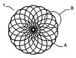
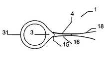
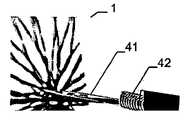
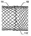
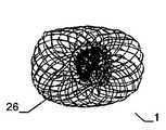
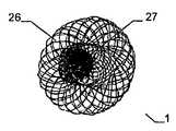
더불어, 인체 및/또는 동물체에서 결손구, 공동, 기관로 등의 폐쇄 또는 부분적인 폐쇄를 위해 사용하거나 또는 벽체, 장기, 공동 등 사이에 형성된 연통구를 제공하기 위한 이식형 장치는, 연장된 제 1 형태 또는 제 1 형태에 비교했을 때 짧은 제 2 형태의 캐리어 구조체와 함께 제공될 수 있고, 캐리어 구조체는 근위부와 원위부를 가지고 있으며, 메쉬 및/또는 층상 구조의 직물 및/또는 거즈의 형태이며, 이 캐리어 구조체의 적어도 한 부분은 나선형(helix-like)으로 감아 올려져 있다. 또한, 캐리어 구조체의 두 부분 역시 나선형으로 감아 올려지는 것이 가능하다. 부분이 나선형으로 감아 올려진다는 사실은, 각각에 대해 접혀져 있는 부분의 두 개의 서브부 덕분에, 그 부분에 이중층 구조만 있을 때보다 캐리어 구조체가 더욱 안정적이 되도록 해준다. 이식형 장치의 세로 범위에 대한 폭으로 배치되는 나선 또는 스파이럴(spiral)의 형태로 자동으로 제 2 형태에서 설정되는 부분은, 거즈, 메쉬, 웨프트, 층상 구조의 직물 등의 형태에서 캐리어 구조체의 공급 덕분에, 종래 기술에서 다르게 알려지고 와이어형 부재로부터 형성되는 스파이럴 형태보다 더욱더 분명하게 안정적이다. 더욱, 이식형 장치는 특히 쉽게 얇은 카테터로 끼워지고 다시 밀어내질 수 있다. 나선형으로 이끄는 반복되는 후방 배치 덕분에, 이식형 장치의 제 2 형태는 아주 큰 용적이 가능하다.In addition, an implantable device for use in closing or partial occlusion of a defect, cavity, organs, etc. in a human body and / or an animal, or for providing a communication port formed between a wall, an organ, a cavity, 1 < / RTI > type or a short second type of carrier structure as compared to the first type, the carrier structure having a proximal and distal portion and being in the form of a mesh and / or layered fabric and / At least a portion of the carrier structure is wound in a helix-like manner. Also, two portions of the carrier structure can be rolled up spirally. The fact that the part is rolled up spirally allows the carrier structure to be more stable than when there is only a bilayer structure at that part, thanks to the two sub-parts of the folded part for each. The portion automatically set in the second form in the form of a spiral or spiral arranged in a widthwise relation to the longitudinal extent of the implantable device can be used in the form of a gauze, a mesh, a weft, Thanks to the supply, is much more stable than the spiral form known from the prior art and formed from a wire-like member. Moreover, the implantable device is particularly easily inserted into a thin catheter and can be pushed back. Thanks to the repeated rearward placement leading to the spiral, the second version of the implantable device is capable of a very large volume.
바람직하게는, 나선형으로 감겨있는 적어도 한 부분은 각자의 다른 부분을 향한 복수의 서브부 그리고 또 다른 부분에서부터 나온 복수의 서브부를 가지고 있다. 각각에 대해 접혀진 나선형 부분의 그러한 서브부의 개수는 어떤 개수라도 선택될 수 있다. 예를 들어 말하자면, 다른 부분을 향한 두 개의 서브부와 그 부분에서부터 나온 두 개의 서브부가 제공될 수 있다. 나선형 부분의 안정성은 서브부의 개수를 선택함으로써 정해질 수 있다.Preferably, at least one portion that is spirally wound has a plurality of sub-portions directed to different portions of one another and a plurality of sub-portions emerging from another portion. Any number of such sub-portions of the helical portion folded for each can be selected. For example, two subparts towards another part and two subparts from that part can be provided. The stability of the helical portion can be determined by selecting the number of sub-portions.
또 다른 부분은 나선형 구성에서 감긴 부분으로부터 동일한 구성 또는 상이한 구성이 될 수 있다. 특히 두 부분은 나선형으로 접힐 수 있으며, 이 경우 일 부분은 다른 부분보다 덜 엄격하게 접힐 수 있다.The other portion may be of the same configuration or different configuration from the wound portion in the helical configuration. In particular, the two parts can be folded in a spiral, in which case one part can be folded less tightly than the other part.
만약 배치가 나선형 구성으로 접힌 두 부분을 가지지 않다면, 나선형 구성으로 접히지 않은 부분은 실질적으로 편평하거나 및/또는 적어도 부분적으로 볼록하거나(bulging) 및/또는 만곡 구성을 취할 수 있다. 구성이 편평한 구성을 취할 때, 그 부분은 예를 들어 디스크 형태(disk-shaped)가 될 수 있거나 두 부분 사이의 원통형 중간부의 직선 곧은 종단의 형태를 할 수 있다. 적어도 부분적으로 볼록한 구성은 만곡형과 함께 조합될 수 있다. 거꾸로, 만곡형 구성은 실질적으로 디스크 형태가 될 수 있다. 그러한 두 부분은 상이한 직경을 가질 수 있다.If the arrangement does not have two parts folded in a helical configuration, the unfolded portion in the helical configuration may be substantially flat and / or at least partially bulging and / or curved. When the configuration assumes a flat configuration, the portion may be, for example, disk-shaped, or it may be in the form of a straight straight end of a cylindrical intermediate portion between the two portions. The at least partially convex configuration can be combined with the curved shape. Conversely, the curved configuration can be substantially disk shaped. Such two parts may have different diameters.
나선형 구성으로 접혀진 부분에는 일반적으로는 관통 개구가 제공된다. 다른 부분은 관통 개구를 가지거나 또는 실질적으로 막혀있을 수 있다. 원칙적으로는 만약 특정 목적에 바람직하다고 생각이 된다면, 슬리브 부재는 함께 붙들려 있는, 즉 차단된 구성의 말단에 잘 맞춰질 수 있다.The folded portion in a helical configuration is generally provided with a through opening. The other portion may have a through opening or may be substantially clogged. In principle, if the sleeve member is deemed desirable for a particular purpose, the sleeve member can be fitted to the end of the retained, i.
또한, 하나 이상의 막 부재가 나선형으로 접혀진 하나 이상의 부분에 및/또는 다른 부분으로 도입되거나 확보될 수 있다. 원리상, 양쪽 부분이 나선형 구성으로 다른 부분에 대하여 접혀지고 막 부재가 하나 또는 모든 부분 내에 또는 상에 제공되는 것이 가능하다.Also, one or more membrane members may be introduced or secured to one or more of the spirally folded portions and / or other portions. In principle, it is possible that both parts are folded in relation to the other part in a spiral configuration and that the membrane part is provided in or on one or all parts.
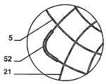
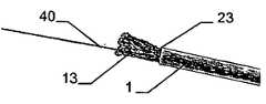
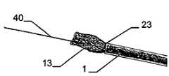
또한, 인체 및/또는 동물체에서 결손구, 공동, 기관로 등의 폐쇄 또는 부분적은 폐쇄를 위해 사용하거나, 또는 벽체, 장기, 공동 등 사이에 형성된 연통구를 제공하기 위한 이식형 장치는, 연장된 제 1 형태는 제 1형태에 비교했을 때 짧은 제 2 형태의 캐리어 구조체와 함께 제공될 수 있고, 여기의 캐리어 구조체는 근위부와 원위부를 가지고 있으며, 메쉬 및/또는 층상 구조의 직물 및/또는 거즈의 형태이며, 제 2 형태에서 적어도 한 부분은 두 개의 서브부를 포함하며, 두 개의 서브부 중 한 부분은 제 1 형태로부터 제 2 형태로 먼저 전개되고, 상기 다른 부분을 향하여 있는 제 2 서브부 상에서 다른 부분으로 향하는 방향으로 접힌다. 이 경우, 접힌 서브부는 바람직하게는 이식형 장치를 향해 내측으로 되접혀진다. 이것은 또한 접힌 서브부 덕분에 한 부분 또는 특히 그 부분의 엣지에 안정성을 부여한다. 외측으로 한 서브부를 되접히는 것에 비교하면, 앞에서 설명된 대로, 내측으로 접힌 서브부는 제 1 형태로 접어 올려질 수 없거나, 또는 만약 이식형 장치가 배치된 후 이식형 장치가 혹시 카테터로 들어가진다면, 제 1 형태로 최소한 거의 접어 올려질 수 없게 된다. 그러므로 이식 위치로부터 한번 배출된 이식형 장치의 제거는 이러한 구현에서는 어렵다고 보인다.An implantable device for use in closing or partially closing a defect, cavity, organs, etc., in a human body and / or an animal, or for providing a communication port formed between a wall, an organ, a cavity, The first form may be provided with a short second type of carrier structure as compared to the first form, wherein the carrier structure has a proximal and a distal part, and the mesh and / or layered fabric and / or gauze In which at least one portion comprises two sub-portions, one of the two sub-portions is first developed from a first form to a second form, and the other of the two sub- Folded in the direction toward the part. In this case, the folded sub-portion is preferably folded back inward toward the implantable device. This also gives stability to one part, or especially to the edge of that part, thanks to the folded sub-part. Compared to folding a sub-section outwardly, as previously described, the inwardly folded sub-section can not be folded up into the first configuration, or if the implantable device is to be introduced into the catheter after the implantable device has been deployed, It can not be folded at least almost in the first form. Removal of the implantable device once drained from the implant location therefore appears to be difficult in this implementation.
한 서브부의 안으로 접힘을 사용할 때, 캐리어 구조체의 곧고 긴 층상 구조의 직물 또는 거즈는 말단에서 특히 잘 보강될 수 있다. 그러한 점에서, 수제작보다 더욱 쉽게 곧고 긴 구조의 제조가 가능하기 때문에, 기계 생산이 특히 적당하다.When using folds in one sub-section, the straight, long layered fabric or gauze of the carrier structure can be particularly well reinforced at the ends. In this respect, machine production is particularly suitable, since it is possible to manufacture straight and long structures more easily than handmade.
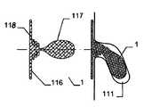
본 발명에 따른 이식형 장치는 특히 바람직하게는 심방 격벽 결손(ASD), 심실 격벽 결손(VSD), 난원공개존(PFO), 심장의 구조적 심방 결손, 좌측 충수(appendix)의 폐쇄에 사용될 수 있으며, 혈관 마개, 즉 말초 혈관계(peripheral flow system)의 말초 혈관 마개 시스템(peripheral vessel closuer system)으로써, 그리고 동맥관개존(PDA)에 사용될 수 있다. 특히, 이식형 장치의 적어도 한 부분의 이중층 구성의 사용은 안정성을 제공함으로써, 심지어 특히 10~12F보다 큰 관이나 개구도 장치에 의해 폐쇄될 수 있다.The implantable device according to the present invention is particularly preferably used for the treatment of atrial septal defect (ASD), ventricular septal defect (VSD), open ovalization zone (PFO), structural heart atrial deficit of the heart and closure of the left appendix , As a vessel stopper, as a peripheral vessel closuer system of the peripheral flow system, and as a ductal conduit (PDA). In particular, the use of a bilayer configuration of at least one portion of the implantable device can be closed by providing a stability, even by a tube or aperture device, especially larger than 10-12F.
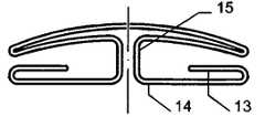
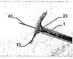
동맥관개존에 대한 이식형 장치의 사용을 위해, 이식 장치가 하나 이상의 이중층 모자 테두리부(hat brim-shaped portion, 모자 테두리-형태 부분)와 함께, 모자 형태(hat-shaped)의 구성을 갖는 것이 바람직하다고 보인다. 그러한 모자 형태는 이식 장치의 머리 부분 형태(head part-shaped)가 동맥관개존의 폐쇄를 위해 동맥관개존에 도입될 수 있도록 한다. 모자 테두리부는 대동맥을 지탱함으로써 대동맥이 자유롭게 있도록 한다.For use of the implantable device for patent ductus arteriosus, it is preferred that the implantation device has a hat-shaped configuration with one or more double brim-shaped portions (hat rim-shaped portions) It seems to be. Such a hat shape allows the head part-shaped of the implant to be introduced into the patent ductus arteriosus for the closure of the patent ductus arteriosus. The cap rim supports the aorta so that the aorta is free.
이중층 모자 테두리부는, 각각에 대해 접힌 적어도 두 개의 서브부를 갖는 부분의 형태를 갖는 것이 보다 바람직하다. 이러한 배치로 인하여, 대동맥 벽체에 대해 지지되기 위한 부분이 특히 안정적이어서, 이에 따라 특히 안전한 고정이 가능하다. 바람직하게는, 대동맥 벽체에 대하여 지탱하는 모자 테두리부는 대동맥에 특히 잘 부착될 수 있도록 대동맥의 곡면에 상응하도록 그 형상이 결정된다. 그러나 이에 추가하여, 각각의 위에서 접힌 모자 테두리부의 서브부에 의해 자동으로 대동맥 구조에 적합하게 변형되며, 안전하고 견고하게 부착될 수 있다. 각각의 위에서 후방으로 접혀지거나 되접혀진 부분의 서브부 및 모자 형태에서 유지되는 구성에 의해, 매우 상이한 직경의 틈이 하나 또는 동일한 이식형 기구에 의해 폐쇄될 수 있다. 예를 들어, 8mm의 직경의 틈이 3mm 이하의 직경을 가진 틈에 사용되는 동일한 모자 형태의 이식형 기구에 의해 밀폐되어 폐쇄될 수 있다. 그러므로 이러한 모자 형태의 이식형 기구 사용의 융통성이 매우 높고, 모자 형태의 특정한 구성에서도 마찬가지다.
모자 테두리부와 마주보는 관계에 있는 이식형 장치의 머리부 부분은, 특히 이식형 장치의 내부로 내측을 향하여 뒤집어 질 수 있다. 이로 인해 그 부분이 폐쇄될 수 있으며, 외측으로 돌출되는 말단 없이 형성되어 그 부분의 형상이 더 쉽게 안정적으로 유지될 수 있을 뿐만 아니라 그 말단에서 이식형 장치 밖으로 돌출된 말단의 손상을 방지할 수 있다.It is more preferred that the double-layer cap rim has the form of a portion having at least two sub-folds folded about each. Due to this arrangement, the portion to be supported against the aortic wall is particularly stable, so that a particularly secure fixation is possible. Preferably, the cap rim that rests against the aortic wall is shaped to correspond to the curved surface of the aorta so that it can adhere particularly well to the aorta. In addition to this, however, it is automatically deformed to conform to the aortic structure by the sub-part of the folded cap rim on each, and can be securely and firmly attached. By virtue of the configuration in which it is held in the shape of the sub-folded portion and the hat-folded portion of the folded back or folded back from above, very different diameters of gaps can be closed by one or the same implantable device. For example, a gap of 8 mm in diameter may be closed and closed by an implantable device of the same hat type used in a gap having a diameter of 3 mm or less. Therefore, the flexibility of using such a hat-shaped implantable device is very high, and it is the same in a specific configuration of the hat-shaped.
The head portion of the implantable device in confronting relation to the cap rim may be inverted, in particular towards the inside of the implantable device. So that the part can be closed and formed without an outwardly projecting end so that the shape of the part can be more easily stably maintained and also the damage of the end protruding out of the implantable device at its end can be prevented .
대안적으로, 모자 테두리부와 마주보는 관계에 있는, 이식형 장치의 머리부 부분은, 머리부 부분으로부터 방울 형태(drop shape)가 형성되도록 이식형 장치로부터 외측을 향하여 뒤집어 지게 될 수 있다. 이러한 형상은 특히 혈관에 삽입되는데 적당하다.Alternatively, the head portion of the implantable device in opposition to the cap rim may be inverted from the implantable device outwardly to form a drop shape from the head portion. This shape is particularly suitable for insertion into blood vessels.
바람직한 형태에서, 이식형 장치의 배치를 위한 본 발명에 따른 방법에서, 카테터를 향한 방향으로 뒤쪽으로 접히는 서브부는 실질적으로 다른 서브부 위로 편평하게 접힐 수 있다. 더불어, 전술한 바와 같이, 카테터를 향한 방향으로 뒤쪽으로 접히는 서브부는 스스로에 대해 나선형으로 둘러싸일 수 있다. 이식형 장치에 대해 위에서 언급된 또 다른 형태는 또한 이식형 장치가 카테터로부터 내밀어질 때 제 2 형태로써 배치될 수 있다. 더불어, 이식형 장치의 적어도 한 부분은 풍선형 형태(balloon-like shape) 또는 특히 이식형 장치로 내측으로 접힌 제 2 서브부와 함께 앵커형으로 돌출된 형상이 될 수 있다. 더불어 이식형 장치의 적어도 한 부분은 실질적으로 편평하거나 및/또는 적어도 볼록한 볼록 또는 오목 구성의 부분에 있으며 및/또는 국면의 볼록 또는 오목형이 될 수 있다. 위에 특정 형상의 혼합형도 역시 가능하며, 이식형 장치의 각각의 부분의 체적과 같이 특정 사용 방법으로 선택될 수 있다.In a preferred form, in the method according to the invention for placement of an implantable device, the sub-folding back in the direction towards the catheter may be folded flat substantially over the other sub-portion. In addition, as discussed above, the sub-folding back in the direction toward the catheter may be helically surrounded by itself. Another embodiment of the implantable device described above can also be deployed in a second configuration when the implantable device is pushed out of the catheter. In addition, at least a portion of the implantable device may be of an anchor-like shape with a balloon-like shape or, in particular, a second sub-section folded inwardly with the implantable device. In addition, at least a portion of the implantable device may be substantially flat and / or at least part of a convex convex or concave configuration and / or may be convex or concave in phase. Mixed forms of a particular shape are also possible, and may be selected for a particular use method, such as the volume of each portion of the implantable device.
만약 이식형 장치, 특히 캐리어 구조체 및/또는 막 부재의 표면 중 적어도 하나가, 하나 이상의 기능성 재료로 처리되거나 코팅된다면 특히 바람직할 것이라고 여겨진다. 이러한 점에 의해, 한편으로는 이식형 장치에 대한 신체의 한 부분의 해로운 반응이 회피되는 반면 다른 한 편으로는 이식 부위를 둘러싼 부분이 약물 치료에 의해 직접적으로 치료될 수 있으며, 따라서 특히 이식형 장치의 효율성이 더욱 향상될 수 있다. 이식형 장치 혹은 이식형 장치의 표면에 사용되는 입히거나 처리하기 위해 사용되는 기능성 재료는 무기 재료(inorganic materials), 세라믹 재료(ceramic materials), 합성 중합체(synthetic polymers), 인간 생체 고분자(human biopolymers), 약물 코팅(medication coatings), 약물-유리 중합체(medication-liberating polymers), 생체분자(biomolecules), 기능기(functional groups) 그리고 유전 물질(genetic materials)에서 선택될 수 있다. 이러한 점에서, 특히 다양한 효과 또는 기능의 조합을 구하는 데, 하나 또는 다수의 재료가 함께 사용되고 조합될 수 있다.It would be particularly desirable if at least one of the surfaces of the implanted device, in particular the carrier structure and / or membrane member, was treated or coated with one or more functional materials. On the one hand, the detrimental reaction of one part of the body to the implantable device is avoided, while on the other hand the part surrounding the implantation site can be treated directly by medication, The efficiency of the apparatus can be further improved. Functional materials used for coating or treating on the surfaces of implantable or implantable devices include inorganic materials, ceramic materials, synthetic polymers, human biopolymers, Can be selected from medication coatings, medication-liberating polymers, biomolecules, functional groups and genetic materials. In this regard, one or a plurality of materials can be used and combined together in particular to obtain various effects or combinations of functions.
특히 바람직하게는, 기능성 재료는 금(gold), 바이오골드(biogold), 다이아몬드형 탄소(DLC), 다이아몬드형 나노복합체(DLN), 산화 이리듐(iridium oxide), 나노다공성 산화(III) 알루미늄(Al2O3), 실리콘 카바이드(silicon carbide), 하이드록실아파티트(hydroxylapatite), 티타늄 산화 질소(titanium nitrite oxide), 폴리(2-클로로-p-크실리렌)(poly(2-chloro-p-xylylene)), 폴리부틸메타크릴레이트(polybutylmethacrylate), 폴리[비스](트리플루오에톡시)포스파젠(poly[bis](trifluroethoxy)phosphazene), 폴리테트라플루오로에틸렌(polytetrafluoroethylene), 폴리우레탄(polyurethane), 콜라겐, 콘드로이틴 설페이트(chondroitin sulfate), 엘라스틴(elastin), 피브린(fibrin), 하이드라우로닉 산(hydrauronic acid), 앱시키맵(abciximab), 헤파린(heparin), 파클리탁셀(paclitaxel), 앱시키맵-유리 셀룰로으즈(abciximab-liberating cellulose), 안지오펩틴-유리 포스포릴클로린(angiopeptin-liberating phosphorylcholine), DNA 유리 폴리에틸렌 비닐아세테이트(DNA liberating polyethylene vinylacetate) 또는 폴리부틸메타크릴레이트(polybutylmethacrylate), 약물-유리 또는 물질-유리 폴리(L-락타이드)(medicament-liberating or substance-liberating poly(L-lactide)), 파크리탁셀 또는 히루딘(hirudin) 또는 아일로프로스트-유리 폴리락타이드(iloprost-liberating polyactide), 바이러스 벡터-유리 폴리락타이드-포스포릴클로린(viral vector-liberating polylactide-phosphorylcholine), 포스콜린-유리 폴리우레탄(forskolin-liberating polyurethane) 및 줄기 세포에서 선택될 수 있다. 이러한 점에서, 예를 들어 표면에 보호막을 입히는 것 또는 항산화 코팅을 하는 것은 산화 이리듐(iridium oxide)에 의해 제공될 수 있다. 폴리우레탄은 예를 들어 얇은 막의 형태로 적용될 수 있다. 생물분자학 기능성기로 기능화된 표면은, 앞에서 언급했던 상황과 관련해서, 분자 표면 공학, 다시 말해 기능성 기의 도입에 의해 분자 물질 표면의 형성으로써 제공될 수 있다. 더불어, 이식형 장치의 표면은 혈액 내에서 순환하는 원구 세포(progenitor cells)의 부착을 위해 예를 들어 셀 리간드 구조에 의해 꼼꼼하게 제공될 수 있다. Poly(L-lactide)는 다수의 약물, 특히 cystostatic 기로부터 나온 약물과 혼합될 수 있으며, 이러한 점에서 각각 바라던 치료 효과가 있을 수 있는 어떤 종류의 약물도 사용하는 것이 가능하다. 예를 들어, 환자의 심장의 구조적 결손 또는 PDA와 같은 구조적 심장의 틈을 폐쇄하기 위해, 중합체와 함께 조합을 이룰 수 있는 물질 또는 약물은 특히 엔도텔리세이션(endothelisation), 다시 말해 생체 특정 세포의 성장을 촉진하기 위한 물질이 될 수 있다.Particularly preferably, the functional material is selected from the group consisting of gold, biogold, diamond-like carbon (DLC), diamond-like nanocomposite (DLN), iridium oxide,2 O3 ), silicon carbide, hydroxylapatite, titanium nitrite oxide, poly (2-chloro-p-xylylene) bis (trifluroethoxy) phosphazene, polytetrafluoroethylene, polyurethane (polyurethane), polyoxyethylene (polyoxypropylene), polyoxypropylene ), Collagen, chondroitin sulfate, elastin, fibrin, hydrauronic acid, abciximab, heparin, paclitaxel, Abciximab-liberating cellulose, angiopeptin-glass Anisotropic agents such as angiopeptin-liberating phosphorylcholine, DNA-liberating polyethylene vinylacetate or polybutylmethacrylate, medicament-free or medicament-liberating or L- free polyol (L-lactide), paclitaxel or hirudin or iloprost-liberating polyactide, viral vector-free polylactide-phospholylcholine -liberating polylactide-phosphorylcholine, forskolin-liberating polyurethane, and stem cells. In this regard, for example, coating the surface with a protective film or applying an antioxidative coating may be provided by iridium oxide. The polyurethane can be applied, for example, in the form of a thin film. Biomolecular functionalized surfaces can be provided by molecular surface engineering, ie, the formation of molecular material surfaces by the introduction of functional groups, in the context of the aforementioned situation. In addition, the surface of the implantable device can be meticulously provided by, for example, a cell ligand structure for attachment of circulating progenitor cells in the blood. Poly (L-lactide) can be mixed with many drugs, especially drugs from the cystostatic group, and it is possible to use any kind of drug that can have the desired therapeutic effect in this respect. For example, a substance or drug that can be combined with a polymer to close a structural defect in the patient's heart or a structural heart gap, such as a PDA, is particularly useful for endothelisation, It can be a material to promote growth.
이식형 장치의 표면 처리는 예를 들어 플라즈마 처리, 특히 DLC(다이아몬드형 탄소) 또는 DLN(다이아몬드형 나노복합체), PVD(물리적 증기 증착) 과정, CVD(화학적 증기 증착) 과정, 이온 주입(ion implantation), 스퍼터링(sputtering), 이온 빔 공정, 레이저 공정, 열공정(thermal process), 스핀 코팅(spin coating), 딥 코팅(dip coating), 에칭(etching) 그리고 전해연마(eletropolishing)의 적용에서의 다양한 과정을 사용하여 수행될 수 있다.The surface treatment of the implantable device can be performed, for example, by plasma treatment, in particular DLC (diamond-like carbon) or DLN (diamond-like nanocomposite), PVD (physical vapor deposition), CVD (chemical vapor deposition) ), Sputtering, ion beam processes, laser processes, thermal processes, spin coating, dip coating, etching, and various applications in electropolishing Process. ≪ / RTI >
이하, 도면을 참조하여 이하에 더욱 상세하게 설명되어 있는 그 예시를 통하여 더욱 상세한 실시 형태에서 본 발명을 설명한다.DETAILED DESCRIPTION OF THE PREFERRED EMBODIMENTS The present invention will now be described in more detail with reference to the accompanying drawings, which are explained in more detail below with reference to the drawings.
도 1a는 본 발명에 따른 이식형 장치 제 1 실시 형태의 평면도를 도시하며,Figure 1A shows a top view of a first embodiment of an implantable device according to the invention,
도 1b는 본 발명에 따른 이식형 장치의 제 2 실시 형태의 평면도를 도시하며,Figure 1B shows a top view of a second embodiment of an implantable device according to the invention,
도 1c 내지 1f는 도 1b의 이식형 장치의 상세도를 도시하며,1C-1F show a detailed view of the implantable device of FIG. 1B,
도 1g 및 1h는 도 1a의 이식형 장치가 배치되어 있는 벽체를 통과하여 섹션의 측면 개념도를 도시하며,Figures 1g and 1h illustrate side schematic views of the section through the wall in which the implantable device of Figure la is disposed,
도 1j는 큰 형태의 관통 개구가 있는 본 발명에 따른 이식형 장치의 제 3 실시 형태의 평면도를 도시하며,Figure 1J shows a top view of a third embodiment of an implantable device according to the invention with a large form of through-opening,
도 1k는 본 발명에 따른 모자-형태의 이식형 장치의 제 4 실시 형태의 사시도를 도시하며,1K shows a perspective view of a fourth embodiment of a cap-type implantable device according to the invention,
도 2a 내지 2c는 본 발명에 따른 이식형 장치의 캐리어 구조체의 단일층, 2층, 및 3층 구조 구조의 상세도를 도시하며,Figures 2a to 2c show a detailed view of the single layer, two layer and three layer structure of the carrier structure of the implantable device according to the invention,
도 2d, 3 및 4는 섞여 짜여진 한 쌍의 부재가 있는 이식형 장치의 캐리어 구조체의 단일층 구조의 구성의 상세도를 도시하며,Figures 2d, 3 and 4 show a detailed view of the construction of the monolayer structure of the carrier structure of the implantable device with a pair of interwoven members,
도 5 내지 13은 본 발명에 따른 이식형 장치의 캐리어 구조체를 형성하기 위해 땋는 방법의 다양한 종류를 상세도를 도시하며,Figures 5 to 13 show detailed views of various types of braiding methods for forming a carrier structure of an implantable device according to the present invention,
도 14 내지 16은 본 발명에 따른 이식형 장치의 또 다른 실시 형태의 평면도 및 그 중심 영역 및 엣지 영역의 상세도를 도시하며,Figures 14 to 16 show a top view of another embodiment of the implantable device according to the invention and a detailed view of its central and edge regions,
도 17은 후방으로 접힌 부분의 상세도를 도시하며,Fig. 17 shows a detailed view of a rear folded portion,
도 18, 21, 22 및 23은 본 발명에 따른 이식형 장치의 또 다른 실시 형태의 평면도 및 그것의 중심 영역 및 두 개의 엣지 영역의 상세도를 도시하며,Figures 18, 21, 22 and 23 show a plan view of another embodiment of an implantable device according to the invention and a detailed view of its central region and two edge regions,
도 19 및 20은 본 발명에 따른 이식형 장치의 또 다른 실시 형태의 전방측 및 후방측의 평면도를 도시하며,19 and 20 show plan views of a front side and a back side of another embodiment of the implantable device according to the present invention,
도 24a 및 24b는 본 발명에 따른 이식형 장치의 또 다른 실시 형태의 측면 개념도를 도시하며,Figures 24A and 24B show side elevational views of another embodiment of an implantable device according to the present invention,
도 25 내지 29는 본 발명에 따른 이식형 장치의 또 다른 실시 형태의 평면도 및 중심 영역, 두 개의 엣지 영역, 그것들 사이에 배치된 영역의 상세도를 도시하며,Figures 25 to 29 show a plan view and a central view of another embodiment of the implantable device according to the invention, two edge areas, a detailed view of the area arranged between them,
도 30 내지 34는 본 발명에 따른 이식형 장치의 막 부재의 배치의 다양한 가능성의 측면도를 도시하며,30 to 34 show side views of various possibilities of the arrangement of the membrane members of the implantable device according to the invention,
도 35 내지 42b는 본 발명에 따른 이식 위치에서 이식형 장치를 위한 배출 과정 동안의 본 발명에 따른 이식형 장치가 있는 카테터의 원리의 측면 개념도를 도시하며,35-42b illustrate side elevational views of the principle of a catheter with an implantable device according to the present invention during an evacuation process for an implantable device in an implantation position according to the present invention,
도 43 내지 58은 카테터로부터 본 발명에 따른 이식형 장치를 위한 배출 과정의 사시도를 도시하며,Figures 43 to 58 show a perspective view of an evacuation process for an implantable device according to the present invention from a catheter,
도 59는 막 부재가 있는 본 발명에 따른 이식형 장치의 실시 형태의 평면도를 도시하며,59 shows a top view of an embodiment of an implantable device according to the invention with a membrane member,
도 60은 막 부재의 다른 배치가 있는 본 발명에 따른 이식형 장치의 또 다른 실시 형태의 평면도를 도시하며,60 shows a top view of another embodiment of an implantable device according to the invention with another arrangement of membrane members,
도 61 내지 64는 이식 위치에 적합한 본 발명에 따른 이식형 장치의 사시도를 도시하며,Figures 61-64 illustrate a perspective view of an implantable device in accordance with the present invention suitable for an implant location,
도 65는 이식 위치에 적합하도록 형성되는 본 발명에 따른 이식형 장치의 또 다른 실시 형태의 사시도를 도시하며,Figure 65 shows a perspective view of another embodiment of an implantable device according to the present invention which is adapted to an implant location,
도 66은 대동맥에 배치되는 본 발명에 따른 이식형 장치 및 대동맥의 측면 개념도를 도시하며,66 shows a side schematic view of an aortic device and an implantable device according to the present invention placed in the aorta,
도 67 및 68은 대동맥 옆에 배치되는 본 발명에 따른 이식형 장치의 측면 개념도를 도시하며,67 and 68 illustrate side elevational views of an implantable device according to the present invention disposed next to the aorta,
도 69 내지 74는 후방으로 나선형 구성으로 복수회 접힌 부분이 있는 본 발명에 따른 이식형 장치의 또 다른 실시 형태의 섹션의 개념도를 도시하며,Figures 69 to 74 show a conceptual diagram of a section of another embodiment of an implantable device according to the present invention having a plurality of folded portions in a backward helical configuration,
도 75는 돌출부, 모자 테두리부 및 이에 대향하는 관계로 배치되는 돌출부가 있는 모자의 형태의, 본 발명에 따른 이식형 장치의 또 다른 실의 사시도를 도시하며,75 shows a perspective view of another thread of an implantable device in accordance with the invention in the form of a cap with protrusions, cap rims and protrusions arranged in opposed relation thereto,
도 76은 실질적으로 원통의 머리 서브부 부분이 있는 본 발명에 따른 모자-형상의 이식형 장치의 또 다른 실시 형태의 사시도를 도시하며,76 shows a perspective view of another embodiment of a cap-shaped implantable device according to the present invention having a substantially cylindrical head sub-portion,
도 77은 배출 와이어에 적용되는, 디스크 형태부 및 볼록부가 있는 본 발명에 따른 이식형 장치의 사시도이며,77 is a perspective view of an implantable device according to the present invention having a disk shaped portion and a convex portion,
도 78 내지 81은 본 발명에 따른 배출 기기 및 본 발명에 따른 이식형 장치의 가느다란 말단 루프의 사시도를 도시하며,78-81 illustrate a perspective view of a draining device according to the invention and of a narrow end loop of an implantable device according to the invention,
도 82는 도 78에 도시된 바와 같이 말단 루프의 평면도를 도시하며,82 shows a top view of the end loop as shown in FIG. 78,
도 83 내지 85는 본 발명에 따른 이식형 장치의 말단 루프의 평면도를 도시하며,83 to 85 show plan views of the end loops of an implantable device according to the invention,
도 86 내지 88은 이식형 장치를 위한 본 발명에 따른 배출 기기의 위치잡기를 도시하는 원리의 개념도를 도시하며,86-88 show a conceptual diagram of the principle of positioning the discharge device according to the invention for an implantable device,
도 89는 배출 와이어 및 유지 와이어의 형태의 배출 기기가 제공되는 본 발명에 따른 이식형 장치의 원리의 사시 개념도를 도시하며,89 shows a perspective view of the principle of the implantable device according to the invention provided with a discharge device in the form of discharge wire and holding wire,
도 90 내지 101은 카테터로부터 밀어내어지고 있는 본 발명에 따른 이식형 장치의 또 다른 실시 형태를 도해하는 사시도를 도시하며,90 to 101 show perspective views illustrating another embodiment of an implantable device according to the present invention being pushed out of the catheter,
도 102 내지 105는 전개 가능한, 스텐트 형태의 본 발명에 따른 이식형 장치의 또 다른 실시 형태의 원리를 도해하는 개념도를 도시하며,Figures 102-105 illustrate a conceptual diagram illustrating the principle of another embodiment of an implantable device in accordance with the present invention in the form of a deployable stent,
도 106은 돌출하여 있는 스텐트 형태의 본 발명에 따른 이식형 장치의 사시도를 도시하며,106 shows a perspective view of an implantable device according to the invention in the form of a protruding stent,
도 107 내지 111은 긴 다리부가 있는 본 발명에 따른 이식형 장치의 중심 영역의 상세도를 도시하며,Figures 107 to 111 show a detailed view of the central region of the implantable device according to the invention with long legs,
도 112 및 113은 중심 영역의 긴 다리부가 있는 본 발명에 따른 두 개의 이식형 장치의 사시도를 도시하며,Figures 112 and 113 show perspective views of two implantable devices in accordance with the present invention with long legs of the central region,
도 114 내지 119는 도 112 및 113의 도시된 이식형 장치 상의 막 부재의 배치의 원리를 도해하는 개념도를 도시하며,Figures 114-119 show a conceptual diagram illustrating the principle of the arrangement of the membrane members on the implantable device shown in Figures 112 and 113,
도 120 및 121은 루프용 두 개의 캐리어링이 있는 본 발명에 따른 이식형 장치의 중심 영역의 상세도를 도시하며,Figures 120 and 121 show a detailed view of the central region of an implantable device according to the invention with two carrier rings for the loop,
도 122는 말아 올려진 돼지꼬리부(pigtail)이 있는 배출 와이어 상의 이식형 장치의 원리를 도해하는 측단면으로서 개념도를 도시하며,122 shows a conceptual diagram as a side cross-sectional view illustrating the principle of an implantable device on a discharge wire with a rolled pigtail,
도 123 내지 125는 이식 위치에 도 122의 이식형 장치를 공급하기 위한 만곡한 밸브 카테터의 원리를 도해하는 개념도를 도시하며,Figures 123 to 125 illustrate a conceptual diagram illustrating the principle of a curved valve catheter for feeding the implantable device of Figure 122 to an implantation location,
도 126은 이식형 장치가 있는 변위 장치를 도시하며,Figure 126 shows a displacement device with an implantable device,
도 127a 내지 127c는 심장의 좌우측 챔버 사이의 벽체에 션트가 있는, 확대된 스케일로 도해되는 심장이 있는 환자의 개념도를 도시하며,Figures 127a through 127c illustrate a conceptual diagram of a patient with a heart that is shown on an enlarged scale with a wall shunt between the left and right chambers of the heart,
은 128은 밸브 카테터의 상세도를 도시하며,Reference numeral 128 denotes a valve catheter in detail,
도 129 및 130은 폴리에스테르 섬유가 있는 스텐트 형태의 이식형 장치의 상세도 및 사시도를 도시하며,129 and 130 show a detail and a perspective view of an implantable device in the form of a stent with polyester fibers,
도 131 내지 133은 도 75에 도시된 이식형 장치의 실시 형태의 변형의 원리를 도해하는 단면도 및 사시도를 도시하며,131 to 133 show a cross-sectional view and a perspective view illustrating the principle of modification of the embodiment of the implantable device shown in Fig. 75,
도 134 내지 137a은 좌측 충수의 폐쇄를 위한, 본 발명에 따른 이식형 장치의 원리를 도해하는 다양한 개념도를 도시하며,Figures 134 to 137a show various conceptual diagrams illustrating the principle of an implantable device according to the present invention for closing the left appendix,
도 137b 및 137c은 도 137a에 도시되는 이식형 장치의 두 개의 절반부의 연결 영역을 상세도를 도시하며,Figures 137b and 137c show a detail view of the connection areas of the two halves of the implantable device shown in Figure 137a,
도 138 내지 140은 도 134 내지 136의 이식형 장치의 변형의 원리를 도해하는 개념도를 도시하며,Figures 138-140 illustrate a conceptual diagram illustrating the principle of modification of the implantable device of Figures 134-136,
도 141 내지 148b은 좌측 충수의 폐쇄를 위한 본 발명에 따른 이식형 장치의 또 다른 실시 형태의 원리를 도해하는 개념도를 도시하며, 및Figures 141 to 148B show a conceptual diagram illustrating the principle of another embodiment of the implantable device according to the present invention for closing the left appendix,
도 149 내지 172는 본 발명에 따른 모자-형상의 이식형 장치의 다양한 변형의 사시도를 도시한다.149 to 172 show perspective views of various modifications of the cap-shaped implantable device according to the present invention.
<도면부호>≪
1 이식형 장치(implantable device)1 Implantable device
1A 제 1 절반부(first half) / 부분1A first half / portion
1B 제 2 절반부(second half) / 부분1B second half / portion
2 개구(opening)2 opening
3 벽체(wall)3 wall
4 막 부재(membrane element)4 membrane element
5 와이어형 부재(wire-like element)5 wire-like element
6 와이어형 부재(wire-like element)6 wire-like element < RTI ID = 0.0 >
7 와이어형 부재(wire-like element)7 wire-like element
8 와이어형 부재(wire-like element)8 wire-like element < RTI ID = 0.0 >
9 와이어형 부재(wire-like element)9 wire-like element
10 근위부(proximal portion)10 proximal portion
11 원위부(distal portion)11 distal portion
12 내부 공간(internal space)12 Internal space
13 서브부(sub-portion)13 sub-portion
14 서브부(sub-portion)14 sub-portion
15 중간부(intermediate portion)15 intermediate portion
16 개구/중심 관통 개구(opening/central through opening)16 opening / central through opening
17 캐리어 구조체(carrier structure)17 Carrier structure
18 외부 엣지(outer edge)18 outer edge
19 부재(element)19 element
20 내부 영역(inner region)20 inner region
21 외부 엣지(outer edge)21 outer edge
22 중심 영역(central region)22 central region
23 카테터(catheter)23 Catheter
23A 밸브 카테터(valve catheter)23A valve catheter
24 주변 연장 엣지(peripherally extending edge)24 Peripherally extending edge
25 근위 말단(proximal end)25 proximal end
26 모자 테두리부(hat brim portion)26 hat brim portion
27 머리부 부분(head part portion)27 Head part portion
30 벽체의 외측(outside of the wall)30 Outside of the wall
31 대동맥(aorta)31 aorta
40 배출 와이어(ejection wire)40 ejection wire
40A 말아 올려진 선단(rolled-up tip) / 돼지꼬리부(pigtail)40A rolled-up tip / pigtail
41 유지 와이어(holding wire)41 holding wire
42 덮개(sheathing)42 sheathing
50 와이어형 부재(wire-like element)50 Wire-like element
51 말단(end)51 end
52 와이어형 부재(wire-like element) / 마커(marker)52 wire-like element / marker
55 와이어형 부재(wire-like element)55 wire-like element
60 와이어형 부재(wire-like element)60 Wire-like element
66 와이어형 부재(wire-like element)66 wire-like element
81 아이 루프(eye loop)81 Eye loop
82 말단(end)82 end
85 캐리어링(carrier ring)85 Carrier ring
87 루프(loop)87 Loop
88 트위스트부(twisted portion)88 Twisted portion
100 심장(heart)100 heart
101 션트(shunt)101 shunt
103 액추에이팅부(actuating portion)103 actuating portion
104 핸들부(handle portion)104 Handle portion
105 섬유(fiber)105 fiber
109 서브부(folded-in sub-portion)109 folded-in sub-portion
110 서브부(sub-portion)110 sub-portion,
111 좌측 충수(left appendix)111 left appendix
112 연결 영역(connecting region)112 Connecting region
112A 다리부(leg portion)112A leg portion
112B 다리부(leg portion)112B leg portion
115 서브부(sub-portion)115 sub-portion
116 디스크 형태부(disk-shaped portion)116 disk-shaped portion < RTI ID = 0.0 >
117 원위부(distal portion) / 풍선형 부분(balloon-like portion)117 distal portion / balloon-like portion
118 중간부(intermediate portion)118 intermediate portion
119 서브부(sub-portion)119 sub-portion
133 서브부(sub-portion)133 sub-portion
142 푸셔(pusher)142 Pusher
144 서브부(sub-portion)144 sub-portion
555 와이어형 부재(wire-like element)555 wire-like element
666 와이어형 부재(wire-like element)666 Wire-like element
x 축x axis
도 1a는 이식형 장치(1)의 정면도를 도시한다. 도 1g 및 1h의 이식형 장치의 측면도에서 명료하게 도시되는 것과 같이 이식형 장치(1)는 예를 들어 인간 또는 동물의 심장의 벽체(3)의 개구(2)에 배치되고 이식형 장치는 근위부(10) 및 원위부(11)를 구비하는데, 도면들은 단지 설명을 위해 벽체(3)에 관한 도면부호가 도 1h에 도시된다는 점만 상이하다. 근위부(10)는 내부 공간(12)을 둘러싸도록 형성되는 반면에, 원위부(11)는 서로에 대해 접혀지는 두 개의 서브부(13, 14)에 의해서 이중층 구성으로 형성된다. 하나의 서브부(13)는 근위부(10)를 향하는 방향으로 구부러져서(bent back) 벽체(3)의 외측(30)을 지탱하는 반면, 다른 서브부(14)는 외측에서 원위로 배치되고, 근위부(10) 및 원위부(11)를 상호 연결하고 벽체(3)의 개구(2)에 배치되는 중간부(15)에 연결된다. 막 부재(4)는 원위의 서브부(14) 상의 외측에 탑재된다. 막 부재는, 중간부를 통과하고 서브부(14)에 의해 내측의 범위를 한정하는 개구(16)를 폐쇄한다. 이는, 이미 그 방향으로 폐쇄되어 있는 근위부와 유사하게, 실질적으로 폐쇄된 구성에 의하여 원위 방향도 폐쇄되어 있는 원위부(11)를 제공한다.1A shows a front view of an
이식형 장치(1)는 도 1b 내지 1f뿐만 아니라 도 1a에서 보다 명확하게 도시되는 캐리어 구조체로 이루어진다. 이는 가장 넓게 변화하는 구성일 수 있으며, 예를 들어, 거즈, 웨프트, 층상 구조의 직물 또는 메쉬의 형태일 수 있다. 도 1b는 4개의 상이한 캐리어 구조체 구성 디자인의 이식형 장치(1)를 도시한다. 도 1b의 좌측 상단 모서리에 도시되며 도 1c에 상세하게 도시되는 구성은, 메쉬 형태의 단일층의 캐리어 구조체를 나타낸다. 이것은 두 개이며 각각이 상호 트위스트된 와이어형 부재(5, 6)가 짜서 형성된다. 도 1e에 도시된 구조는 2층 구조이고, 물론 두 개의 서로 트위스트된 와이어형 부재(5, 6)를 짜서 형성된다. 도 1d에 도시된 구조는 3층 구조이고, 도 1f에 도시된 구조는 4층 구조이며, 이들 모두는 두 개의 서로 트위스트된 와이어형 부재(5, 6)를 짜서 형성된다. 이식형 장치의 도 1a에 도시된 실시 형태는 4층 캐리어 구조체를 포함하여, 서로에 대해 접혀지는 두 개의 서브부(13, 14)의 영역에서 특히 치밀하다. 주변으로 연장하는 이식형 장치의 외부 엣지(18)는 도 1a 내지 1f의 실시 형태에서 균일하게 만곡되는 구성이다.The
도 1j는, 도 1a 내지 1h의 실시 형태와는 다른 이식형 장치(1)의 또 다른 실시 형태를 도시하는데, 여기에 이식형 장치를 관통하는 넓은 관통 개구(16)가 존재한다. 이러한 넓은 관통 개구가 있기에, 예를 들어 벽체 또는 기관로의 부분 폐쇄의 경우 명료한 관통 개구를 제공할 수 있다.Fig. 1J shows another embodiment of the
도 1k는 특히 지속성 동맥관(persistent ductus arteriosus)(PDA)의 치료용으로 설계된 이식형 장치(1)의 실시 형태를 도시한다. 이러한 PDA의 폐쇄를 위한 대응하는 구성은 이하에 더욱 상세하게 논의될 도 75 및 76에서도 보인다. 이러한 모든 실시 형태는 거의 모자-형상의 구성이다.Figure 1K shows an embodiment of an
도 2a 내지 13은 와이어형 부재의 짜임(weaving) 또는 엮임(interlacing)에 관한 변형된 예시들을 도시하는데, 원칙적으로 가능한 형태만을 예시적으로 도시한다. 도시된 형태의 다수의 또 다른 변형 및 조합이 형성될 수 있다는 점을 주지하여야 한다. 도 2a는 두 개의 와이어형 부재(5, 6)를 포함하는 단일층 메쉬를 도시한다. 도 2b는 하나의 층에서의 와이어형 부재(5, 6) 및 다른 층에서의 와이어형 부재(55, 66)를 포함하는 이중층 메쉬를 도시한다. 도 2c는 하나의 층에서의 와이어형 부재(5, 6), 제 2 층에서의 와이어형 부재(55, 56), 및 제 3 층에서의 와이어형 부재(555, 666)를 포함하는 3층 메쉬를 도시한다. 도 2d는 서로 평행의 병렬 배치되는 관계로서 연장하는 두 개의 각각 와이어형 부재(5, 6)에 의해 형성되는 단일층 메쉬를 도시한다. 도 3 및 4는 상호 서로 평행의 관계로서 연장하는 두 개의 와이어형 부재(5, 6)가 함께 트위스트되고, 각각 트위스트된 한 쌍의 와이어형 부재(5, 6)가 순서대로 서로 엮이는 변형을 도시한다. 이들 두 개의 실시 형태에서 유일한 차이점은 서로를 통과하여 개개의 쌍을 엮는(lacing) 방식이다. 도 3에 도시된 실시 형태에서는 각각 트위스트된 한 쌍이 트위스트된 다른 한 쌍의 와이어형 부재 사이를 함께 통과하게 되는 반면, 도 4의 실시 형태에서는 개개의 와이어형 부재(5, 6)가 교차점에서 서로 지나친다.Figs. 2A to 13 illustrate modified examples of weaving or interlacing of a wire-like member, which illustratively illustrate only possible forms in principle. It should be noted that many further variations and combinations of the illustrated forms can be made. Figure 2a shows a single layer mesh comprising two wire-
도 5는 개개의 와이어형 부재가 서로 엮일 수 있고, 각각 제 1 케이스에서는 두 개의 와이어형 부재(5, 6)가 서로 엮이고, 제 2 케이스에서는 4개의 와이어형 부재(5, 6, 7, 8)가 서로 엮이고, 제 3 케이스에서는 6개의 와이어형 부재(5, 6, 7, 8, 9, 50, 60)가 서로 엮이는 또 다른 가능한 방식을 도시한다.5 shows a state in which the individual wire-like members are interwoven with each other and two wire-
도 6은 엮임 또는 거즈 변형을 도시하는데, 개개의 매끄러운 와이어형 부재(7)가 한 쌍의 엮인 와이어형 부재(5, 6)와 짜여지거나 서로 엮인다. 도 7은 오직 하나의 단일 매끄러운 와이어형 부재(7)가 매끄러운 와이어형 부재(7)와 대응하게 그리고 4개의 와이어형 부재(5, 6, 8, 9)를 포함하는 메쉬와 대안적으로 짜여지는 또는 서로 엮이는 변형을 도시한다. 도 8에서는 6개의 와이어형 부재 및 한 쌍의 와이어형 부재(5, 6)를 포함하는 메쉬 배치의 조합이 한 쌍의 트위스트된 와이어형 부재와 서로 엮이고 대안적으로 배치된다. 도 9 및 10은 상호 다시 짜여지고 또는 서로 엮이는 5개의 또는 6개의 엮인 와이어형 부재(5, 6, 7, 8, 9, 60)를 각각 포함하는 조합을 도시한다. 도 11은 각각 트위스트된 한 쌍의 와이어형 부재(5, 6)를 포함하는 메쉬 배치를 도시한다. 도 12는 매끄러운 와이어형 부재(7) 및 트위스트된 한 쌍의 와이어형 부재(5, 6)를 대안적으로 포함하는 메쉬 배치를 도시한다. 도 13은 서로 엮이지 않은 3개의 매끄러운 와이어형 부재(5, 6, 7)를 포함하고 그리고 이에 상응하는 방법으로서 3개의 매끄러운 와이어형 부재 및 오직 두 개의 매끄러운 와이어형 부재(5, 6)를 대안적으로 포함하는 메쉬 배치를 도시한다. 각각의 와이어형 부재는 둥근 또는 평평한 단면 형상 또는 임의의 다른 형태의 단면 형상일 수 있다.Fig. 6 shows an interwoven or gauze deformation, in which individual smooth wire-
도 14는 규칙적인 동심 형태인 이식형 장치(1)의 실시 형태를 개념적으로 도시한다. 원칙적으로는, 예를 들어 이식형 장치(1)가 한쪽 측면에서 한계가 정해지는 위치에서 예를 들어 벽체 또는 대동맥 또는 기타의 다른 형태에 의해 환자의 몸체에 이식되는 경우, 이식형 장치에 있어서 편심 형태가 제공되는 것도 가능하다. 이러한 특성의 실시 형태는 도 61 내지 68을 참조하여 더욱 상세히 논의될 것이다. 도 14에서 이식형 장치(1)의 두 개의 상세 섹션(A, B)이 표시되는데, 이는 도 15(상세도 A) 및 16(상세도 B)에서 상세히 도시된다. 이 점에 있어서, 이식형 장치의 중심을 도시하는 도 15는 원위부, 중간부 및 근위부를 통하여 연장하는 작은 중심의 관통 개구(16)를 명백하게 도시한다. 여기에서, 캐리어 구조체(17)는 와이어형 부재(5)로부터 규칙적인 메쉬의 방식으로 형성된다. 이식형 장치(1)의 엣지의, 도 16에 도시되는 상세도 B는, 외부 엣지(18)가 막 부재(4)를 고정하는 역할을 하는 추가적인 부재(19)에 의해 싸이는(wrapped) 것을 도해한다. 그러므로 부재(19)는, 예를 들어 프로렌인 강심제-외과 봉합(cardiac-surgical suture) 재료의 실형(thread-like)의 또는 와이어 부재의 형태일 수 있다. 게다가 추가적인 부재는, 이하에서 자세히 설명되는 것과 같이, 이식 진행 동안 모니터링 장치 하에서 이식형 장치를 명백히 식별하기 위한 마커(marker)로서도 제공될 수 있다. 이식형 장치의 외부 엣지(18)는 원위부의 근위 방향으로 마주하는 서브부(13) 및 원위로 마주하는 서브부(14)가 서로 인접하거나 또는 서로 섞이는 영역이다. 이는 도 1g 및 도 1h에서 보여질 수 있다.Fig. 14 conceptually shows an embodiment of an
이식형 장치(1)의 캐리어 구조체(17)는 치밀하고 콤팩트하여 이미 일종의 막을 형성한다. 하지만, 이와 같은 경우가 아니거나, 또는 환자의 심장 내의 결손구와 같은 개구의 완전한 실링(sealing) 폐쇄를 원한다면, 캐리어 구조체의 메쉬 구성 또는 웨프트 하에서 도 16의 예에 의해 개념적으로 도시되는 추가적인 막 부재(4)가 제공될 수 있다. 도 30 내지 34에 도시되는 바와 같이 막 부재는 이식형 장치(1)의 원위부(11)의 위치에서 서브부(14) 상에 원위로 맞추어 질 수 있을 뿐만 아니라, 도 1 및 도 30에서도 도시된 바와 같이 그 외측 상에서 그리고 이식형 장치 내측의 다른 위치에서도 제공될 수 있다. 매우 작은 막 부재(4)의 도 32에 도시된 변형은 중간부(15)의 개구(16) 내에 배치된다. 막 부재가 더 작아지면, 캐리어 구조체(17)의 메쉬 또는 거즈에 따른 응고 위험성이 감소되는데, 다시 말해 벽체(3)에서 폐쇄되는 개구(2) 둘레에는 오직 그 재료만이 존재하고 위험을 증가시키고 트레블링 색전증(travelling embolism)로 인한 두통 및 일시적인 시각상실을 초래할 수 있는 캐리어 구조체와 막 부재의 재료의 조합은 존재하지 않는다. 여기에서 이러한 합병증은 신뢰성있게 회피될 수 있다. 동일한 점이 도 31, 33 및 34의 다른 변형에 적용되는데, 도 31에 관해서는 막 부재가 근위부(10)의 내부 공간에 배치되고, 예를 들어 그 내부 상에 주변으로 연장하는 외부 엣지(18)에 고정된다. 도 33에서는, 막 부재가 근위부(10)의 원위 서브부를 지탱하는 조건에서 근위부(10)에 의해 규정되는 내부 공간(12)에 배치 및 고정되며, 이는 이식형 장치가 벽체의 홀 내에 배치되는 경우 벽체를 지탱하고 중간부로 들어간다. 도 34에서, 막 부재는 그 근위 내부측 상에서, 근위부(10)에 의해 규정된 내부 공간에 배치된다. 막 부재는 예를 들어 중합체와 같은 플라스틱 재료를 포함할 수 있다.The
도 17은, 도 14 및 16에서 도시되지 않는, 원위부(11)의 되접히거나(back-folded) 후방으로 접힌(rearwardly folded) 서브부(13)의 상세를 도시한다. 여기에서, 상대적으로 좁은 구성이다. 균등하게 넓혀지고 심지어 이식형 장치의 중심까지 연장할 수 있다.17 shows the details of the sub-portion 13 rearwardly folded rearwardly of the
도 18 및 21 내지 23은 도 14의 이식형 장치(1)의 실시 형태에서 변형된 실시 형태를 도시하며, 여기에서 주변으로 연장하는 외부 엣지(18)를 위한 상이한 구성을 포함한다. 이 점에 있어서 도 18은 근위부(10)의 평면도를 도시하고 도 21는 작은 관통 개구(16) 및 와이어형 부재(5)의 두 개의 말단이 있는 이식형 장치의 중심의 상세도를 도시하고, 그리고 이는 와이어형 부재(5)의 또 다른 부분이 있는 캐리어 구조체(17) 내에서 중심으로 서로 엮인다.Figs. 18 and 21-23 illustrate a modified embodiment of the embodiment of the
도 18의 상세도 D에서 상세하게 도시되는 바와 같이, 도 22에서는 구조체는 둘레에서 싸이는 근위부(10)의 외부 엣지(18) 대신 와이어형 부재(52) 등으로 둘레에서 부분적으로 감긴 캐리어 구조체의 루프만을 포함한다. 이것은 예를 들어 X-레이 유닛 하에서 이식형 장치를 시각적으로 나타내기 위한 마커로서 역할을 한다. 그러한 목적으로 위해, 예를 들어 도해된 와이어형 부재(52)는, 예를 들어 30 내지 10% 이리듐 그리고 70 내지 90% 백금 비율로 이루어지는 백금 및 이리듐(iridium)을 함유하는 재료로부터 생성되는 미세나선의 형태이다. 도 23에서 도시된 바와 같이, 도 18에서 상세도 E에서 상세하게 도시되는 바와 같이, 이식형 장치(1)는 단일의 와이어형 부재로부터 형성된다. 여기에서, 그 말단(51)은 원하지 않는 헐거움을 방지하기 위해 외부 엣지(21) 영역에서 서로 엮인다.As shown in detail in detail D of FIG. 18, in FIG. 22, the structure may include a carrier structure partially wrapped around the periphery by a wire-
삭제delete
도 19는 근위부(10)의 정면도를 도시하며, 도 20은 이식형 장치(1)의 또 다른 실시 형태의 원위부(11)의 평면도를 도시한다. 이 점에 있어서 이러한 실시 형태에서는 근위부(10)에 원위부(11)를 향하는 방향으로 후방으로 접히는 서브부 및 근위 방향으로 마주하는 서브부가 제공된다는 점이 명백할 것이며, 다시 말해 도 1에 도시된 원위부의 그것에 대응하는 구성 설계로 이루어진다는 점이 명백해질 것이다. 캐리어 구조체(17)는 예를 들어 도 14의 실시 형태보다 더 치밀해진다. 이는 특히 근위부(10) 좌측에 실질적으로 관통 개구가 없기 때문에, 중심 영역에서 명백히 보인다. 각각 구성을 갖는 캐리어 구조체(17)의 개별적이고 규칙적으로 배치된 세그먼트(segment)는 각각이 예를 들어 3%의 공차로서 α = 20o의 각도를 차지할 수 있다.19 shows a front view of the
도 24a는 원위부(11)가 평평하거나 균등한 구성이지만 근위부(10)가 만곡하게 폐쇄된 구성인 이식형 장치의 원리를 도해하는 측면 개념도를 도시한다. 도 24b에서는, 원위부(11)가 상호 되접히는 서브부(13, 14)로 형성된다.Figure 24a shows a side elevational schematic diagram illustrating the principle of an implantable device with a configuration in which the
도 14에 도시된 것과는 다르나 도 19 및 20에 도시된 것과 동일한, 도 25에 도시된 이식형 장치의 실시 형태는, 도 25, 도 26에 표시된 상세도 F에서 상세하게 알 수 있는 바와 같이, 근위부(10)가 이러한 중심 개구를 가지지 않고, 그 중심 영역(22)에서 실질적으로 폐쇄된 구성이기 때문에, 본질적으로 관통 개구를 가지지 않는다. 도 25, 도 27에 표시된 상세도 G에서 상세하게 알 수 있는 바와 같이, 중심 영역을 둘러싸는 영역에서 안정하지만 많은 개구를 만들기 위해, 개개의 와이어형 부재는 캐리어 구조체(17)의 중심 영역(22)을 둘러싸는 영역에서 섞여 짜여진다. 와이어형 부재(5)의 말단(51)은 원하지 않는 헐거움을 방지하여 결속되도록 와이어형 부재의 일부와 그 중심 영역에서 섞여 짜여진다. 여기에서, 외부 엣지(18)에는 어떠한 막 부재도 제공되지 않기 때문에 막 부재를 고정하는 부재에 싸이지 않는다. 이는, 도 29에 도시된 바와 같이, 도 25의 상세도 I 및 도 28의 외부 엣지(18)의 상세도 H 모두로부터 보여질 수 있다.The embodiment of the implantable device shown in Fig. 25, which is different from that shown in Fig. 14, but the same as that shown in Figs. 19 and 20, as can be seen in detail in the detail view F shown in Figs. 25 and 26, Since it does not have such a central opening and is substantially closed in its
도 59는 고정되는 막 부재(4)가 구비된 변형 형태에서 도 25의 이식형 장치의 실시 형태를 도시한다. 막 부재(4)가 전체 캐리어 구조체(17)를 지탱하여, 캐리어 구조체의 주변 연장 엣지가 자유롭지 못하다. 따라서 이식형 장치(1)의 엣지 영역에서의 색전증 발생의 위험이 낮아진다. 막 부재(4)는 도 59에 도시된, 근위부의 내부 영역(20)을 너머 그리고 여기에서 실질적으로 폐쇄된 특성으로 이루어지는 근위 말단(25)을 너머 연장한다. 막 부재(4)는 예를 들어 봉합되어 있는 이식형 장치(1)의 캐리어 구조체(17)의 주변 연장 엣지(24)에 고정된다.Fig. 59 shows an embodiment of the implantable device of Fig. 25 in a variant in which a
도 35 내지 42b는 벽체(3)의 개구(2) 내에 이식형 장치(1)의 배치에 관련된 과정을 개념적으로 도시한다. 도 43 내지 58은 사시도로서 도시되는 이식형 장치(1)를 상세한 예시로서 도시한다. 도 35 및 도 43의 제 1 단계에서, 가이드 또는 배출 와이어(40) 및 결과적으로 이를 에워싸며 축(X)을 따라 연장되며 배출 와이어를 둘러싸는 제 1 조건의 카테터(23) 내에 이식형 장치가 배치되는 카테터(23)가 개구(2)를 통하여 밀린다. 이러한 전진하는 움직임을 만들기 위해, 예를 들어 이식형 장치(1)에 고정된 유지 와이어(41)는 배출 와이어(40)에 대하여 상대적으로 이동된다. 유지 와이어(41)를 이식형 장치에 맞추는 방식은 도 78 내지 89를 참조하여 아래에서 더욱 상세하게 설명될 것이다. 제 2 단계에서, 이식형 장치(1)는 배출 와이어(40)를 따라 카테터(23)로부터 밀어내어진다(push out). 이 경우, 나중에 벽체(3)를 지탱할 원위부(11)의 서브부(13)가 먼저 전개된다. 이는 특히 도 36 및 37 및 도 44 내지 47로부터 알 수 있다. 근위 방향으로 되접히는 구성이 서브부(13)에 부여된다는 점을 명백히 알 수 있다. 바람직하게는, 이식형 장치(1)의 재료는 특히 니티놀과 같은 형상 기억 재료 또는 플라스틱 재료일 수 있으며, 또는 예를 들어 이식형 장치의 다중층 캐리어 구조체인 경우에 그 조합일 수 있다.Figures 35 to 42b conceptually illustrate the process related to the placement of the
도 39 및 48 내지 50에서 도시되는 바와 같이, 이식형 장치(1)가 카테터(23)로부터 더 밀어내어지는 경우, 원위부(11)의 제 1 서브부(14)가 전개된다. 이식형 장치(1)가 카테터(23)로부터 더 밀어내어질수록, 이식형 장치가 카테터(23)로부터 더 밀어내어지면 서브부(13)는 서브부(14) 상에서 한층 더 되접히고 한층 더 이를 지탱한다.When the
이식형 장치(1)가 카테터로부터 더욱 밀어내어지는 경우, 도 40 내지 42 및 51 내지 57에서 도시되는 바와 같이, 근위부(10) 또한 점진적으로 전개된다. 이 경우, 근위부(10)는 신속하게 연장하고 주변 연장 엣지(24)를 형성하며, 이에 따라 근위부 역시 이중층 구성이 된다. 하지만, 근위부(10)의 근위 말단(25)은 폐쇄되도록 결합되거나 또는 최소한의 개구가 제공되는 구성이어서, 이로 인해 내부 공간(12)의 범위가 정해진다는 점을 유의한다.When the
이식형 장치가 카테터로부터 완전히 밀어내어지고 이 경우 제 2 형태로 전개된 경우, 예를 들어 도 42a 또는 42b 및 58에 도시된 형상이 된다. 도 42a에 도시된 실시 형태와는 달리, 도 42b의 실시 형태에는 원위부 상에 막 부재(4)가 제공된다. 근위부(10)에 관하여 실질적으로 평평한 형상 대신에, 도면에 도시된 바와 같이, 볼록한 구성일 수도 있고, 다시 말해 더 넓은 내부 공간을 에워쌀 수 있고, 및/또는 예를 들어 도 24b에 예로서 도시된 바와 같이, 만곡할 수도 있다.When the implantable device is fully pushed out of the catheter and deployed in this case to the second configuration, for example, the configuration shown in Figures 42a or 42b and 58 is achieved. Unlike the embodiment shown in Figure 42 (a), the embodiment of Figure 42 (b) is provided with a
원하는 바에 따라 전부 또는 일부 폐쇄가 주어지는 방식으로 이식형 장치가 이식 위치에서 맞추어 지는 경우, 유지 와이어(41) 및 배출 와이어(40)의 형태인 배출 기기에 의해 이식형 장치가 분리될 수 있다. 상응하는 도면이 도 42b 및 58에서 확인될 수 있다. 만약 또 다른 조정이 여전히 요구된다면, 원하는 위치에 도달할 때까지 배출 와이어 및 유지 와이어의 상대적 이동에 의해 영향을 받을 수 있다. 이 점에 있어서, 예를 들어, 이를 통과하는 배출 와이어 및 유지 와이어가 구비된 이식형 장치의 측면 개념도인 도 87이 도시하는 바와 같이, 이식형 장치의 회전도 가능하다. 도 88에 개념적으로 도시된 바와 같이, 배출 와이어(40) 및 유지 와이어(41) 둘레의 이식형 장치의 부유(floatation)도 가능하다. 가이드 또는 배출 와이어(40)는 전체적으로 매우 얇은 특성을 가지고 매우 얇은 선단(tip)을 가지므로 배출 와이어에 의해 이식형 장치의 부유가 가능하다. 배출 와이어의 선단은 0.1 내지 0.3mm 사이의 직경을 가질 수 있다. 도 86에 나타난 바와 같이, 배출 와이어(40)에 관하여 어떠한 각도를 가정할 수 있다. 이러한 방식에 의하여, 이러한 방식을 갖지 않았다면 이식형 장치가 인체 또는 동물체에서 접근하기 곤란할 수 있었던 문제가 있는 이식 위치에서도, 별다른 문제가 없을 수 있다.The implantable device can be separated by the drainage device in the form of the holding
도 60에서 이식형 장치(1)의 평면도로부터 볼 수 있는 바와 같이, 도 58에 도시된 것과 비교해 볼 때 본 실시 형태는 막 부재(4)가 제공되는 변형을 포함한다. 이는 이식형 장치(1)보다 더 작은 직경이어서, 캐리어 구조체(17)의 엣지가 막 부재(4) 둘레로의 연장 관계에서 자유롭게 유지된다. 막 부재(4)는 원위로 지시되는 원위부(11)의 서브부(14) 상에 고정되고, 특히 거기에 봉합 또는 접착된다. 도 60에 도시된 바와 같이, 배출 와이어(40)는 막 부재(4) 및 이식형 장치(1)의 중심을 통과한다.As can be seen from the top view of
이식형 장치의 위치잡기는 예를 들어, 이미지화 공정에 의해 추적(tracking)될 수 있고, 이 경우 예를 들어 소정의 위치에서 이식형 장치는 이미지화 공정이 사용되는 경우 가시적인 마커(marker)로서 전술한 와이어형 부재(52)를 구비할 수 있다. 이러한 마커는 예를 들어 캐리어 구조체(17)의 표면에 제공되거나 또는 도 22에 도시된 바와 같이 엣지에 제공될 수 있는데, 이 경우 엣지에서 이를 배치하는 것이 이식형 장치의 경계 윤곽(contour)이 명확히 검출될 수 있기에 보다 바람직함을 확인하였다.The positioning of the implantable device can, for example, be tracked by an imaging process, for example at a given location, the implantable device can be used as a visible marker when an imaging process is used, And a wire-
이식형 장치(1)는 그것이 배치되는 개구(2)의 어떠한 형상에도 적용될 수 있다. 예를 들어, 타원형의 개구에 맞추어 지는 경우 타원형이 될 수 있고 또는 다각형의 개구에 맞추어 지는 경우 다각형이 될 수 있다. 도 61 내지 64는 이러한 변형 형태를 도시한다. 이 경우, 전체 이식형 장치는 이식 위치에서의 구조체, 특히 벽체에 적용되기 위해 모든 축 둘레로 만곡할 수 있다. 일 부분의 후방으로 접혀진 서브부에 의해 이중층 구성인 부분으로 인하여, 여느 문제들 없이 이식형 장치는 이식 위치에서 모든 구성에 적합하고, 변형에도 불구하고 안정된 위치를 가정할 수 있으며, 이식 위치에서 신속하고 균일하게 조여질 수 있다.The
또한, 이식을 더욱 향상시키도록, 제 2 형태가 부여된 경우 상응하게 형성된 개구에 대한 양호한 맞춤을 위해, 생산시 이식형 장치에는 이미 만곡되거나 및/또는 타원형의, 다각형의 또는 다른 구성이 제공될 수도 있다. 이러한 종류의 실시 형태가 도 65에 예를 들어 도시된다. 여기에서, 원위부 및 근위부(10, 11)는 동물의 열린 구강과 같이 서로로부터 부분적으로 구부러진다. 더 나은 지향(orientation)을 위해, 도 65는 원위부(11) 및 근위부(10)의 서로 상에서 접히는 두 개의 서브부(13, 14)뿐만 아니라, 원위부(11)의 외부 엣지(18) 및 중간부(15)를 도시한다. 이식형 장치(1)에 부여되는 이러한 특징적인 구성은, 예를 들어 대동맥 상의 역압(adverse pressure)을 피하기 위해 제공된다. 도 66 내지 68로부터 볼 수 있는 바와 같이, 이식형 장치는 이러한 대동맥(31) 둘레로 배치될 수 있어서, 대동맥 벽체를 손상시키는 위험이 더 이상 발생하지 않는다. 이와 관련하여, 도 66은 막 부재(4)가 제공되는 이식형 장치(1)의 평면도를 도시하고, 도 67 및 68은 이식형 장치(1)의 측면도를 도시한다. 모든 경우에 있어서, 이식형 장치가 대동맥(31) 둘레로 맞추어 지는 것이 명백히 보여질 수 있다. 도 68에 도시되는 바와 같이, 평면도에서 중간부는 이식형 장치에 대하여 편심으로 배치될 수 있어, 그 결과 이식형 장치가 편심 구성이다.Further, for better fitting of the correspondingly formed opening when the second configuration is given, the implantable device at the time of production may be provided with already curved and / or elliptical, polygonal or other configurations to further improve the implantation It is possible. This kind of embodiment is shown by way of example in Fig. Here, the distal and
삭제delete
이식형 장치는 ASD, VSD 또는 PFO 폐쇄 장치, 혈관(vascular) 폐쇄 장치 또는 좌측 심장귀(cardiac auricle) 폐쇄 장치와 같은, 광범위한 문제에 대하여 사용될 수 있다.Implantable devices can be used for a wide range of problems, such as ASD, VSD or PFO occlusion devices, vascular occlusion devices or left cardiac auricle occlusion devices.
하지만, 도 69 내지 74는 앞선 실시 형태와는 대조적으로, 하나 이상의 부분이 나선형 구성으로 감아 올려지는 이식형 장치(1)의 또 다른 실시 형태를 도시한다. 이 경우, 서브부(13)가 서브부(14)에 되접혀지거나 또는 후방으로 접히는 두 개의 서브부(13 및 14)에 추가하여, 그것이 카테터로부터 더욱 밀어내어지고 그리고 제 2 형태가 제공되는 경우, 이식형 장치에 의한 적어도 하나의 다른 되접힘 또는 후방으로의 접힘이 효과적이다. 또한, 두 개의 서브부(13 및 14)는 자신의 둘레에서 적어도 한번 접힌다. 이는, 종래 기술의 이식형 장치와 비교하여, 이러한 부분들에 보다 안정성을 제공한다.However, Figures 69-74 illustrate another embodiment of an
제 1 형태로부터 제 2 형태로의 이식형 장치(1)의 전개시에 먼저 전개되는 서브부는 서브부(133)이다. 이식형 장치가 카테터(23)로부터 더욱 밀어내어지는 경우, 서브부(133)는 원위 방향으로 접혀진 서브부(144)를 따라오는데, 서브부(133)는 근위 방향으로 접힌다. 이식형 장치가 카테터로부터 더욱 밀어내어지는 경우, 서브부(13)는 서브부(133) 상에 접히고 후속하여 서브부(14)는 서브부(144) 상에 접힌다. 도면에 도시되지 않지만, 또 다른 서브부가 이러한 방식으로 상호 접힐 수 있어서, 그 결과 더 크거나 또는 더 작은 두께의 나선형이 된다.The sub-portion first developed in the development of the
다른 실시 형태에서와 같이, 이식형 장치(1)의 구성의 나머지는 원하는 바와 같이 될 수 있다. 도 69에 도시된 바와 같이 오직 일 부분에만 나선형 구성이 제공되는 반면, 다른 부분은 실질적으로 평평한 디스크 형태 또는 모루형(anvil-like) 구성이고 작은 관통 개구를 가진다. 관통 개구(16)는 외측에 배치되어 있는 막 부재(4)에 의해 나선형부에서 폐쇄된다. 도 70의 실시 형태의 경우, 다시 일 부분이 나선형 구성이다. 다른 부분은 결합되어, 오무려지는(retracted) 근위 말단(25)이 있는, 볼록하고 만곡한 구성으로 형성된다. 도 70의 실시 형태와는 달리, 도 71의 실시 형태는 근위부가 실질적으로 평평하게 만곡한 구성으로 형성되고 나선형부보다 큰 직경을 가진다. 근위부의 내부의 근위 말단(25)은 함께 이끌린다. 대조적으로, 도 74에 도시된 근위부는 거의 나선형부과 같이 동일한 직경으로 이루어지고 폐쇄된 만곡부 내에 막 부재(4)를 가진다.As in other embodiments, the remainder of the configuration of the
도 72의 실시 형태는 도 69에 도시된 것과 유사하지만, 상대적으로 넓은 관통 개구가 디스크 형태부에 제공되고 막 부재(4)가 거기에 배치된다는 점에서 차이가 있다. 디스크 형태부의 관통 개구는 이식형 장치 그 자체가 통과하는 관통 개구에 거의 대응한다.The embodiment of Figure 72 is similar to that shown in Figure 69, but differs in that a relatively wide through opening is provided in the disc shaped portion and a
도 73에 도시된 실시 형태는 나선형 구성으로 감겨지거나 또는 접혀 올라가는 두 개의 부분을 구비한다. 이 경우, 근위부(10)는 근위 방향에서 후방으로 접혀지거나 또는 되접히는 서브부(110)를 포함하고, 이는 서브부를 원위로 마주하고, 다음 서브부를 근위로 마주한다. 그러므로 근위부는 복수회 서로 접혀져 있는 서브부에 의해 나선형 구성일 수 있다.The embodiment shown in Figure 73 has two portions that are rolled up or folded in a spiral configuration. In this case, the
도 75 및 76은, 전술한 도 1k와 같이, PDA를 폐쇄하기 위해 적절한, 이식형 장치(1)의 모자-형상의 구성을 도시한다. 이 경우, 이식형 장치는 결손구로 삽입되고 일 부분이 대동맥 벽체를 지탱한다. 바람직하게, 상기 일 부분은 적어도 한번 되접혀지는 서브부가 제공되는 부분인데, 그 부분이 대응하는 구성이라 생각할 수 있거나 또는 제 2 형태로서 부여됨에 따라 적용될 수 있기 때문이다. 그러므로 전술한 도면에 있어서 모자 형상이 적합한데, 적어도 한번은 후방으로 접혀지거나 되접히는 모자 테두리부(26)에 따른 각각의 모자 테두리가 대동맥 벽체의 구성에 적합할 수 있고 거기서 신속하게 안정하게 될 수 있기 때문이다. 도 1k의 실시 형태는 모자의 머리부 부분을 형성하는 하나의 짧고 둥근 머리부 부분(27)만을 가지는 반면에, 도 76에서는 특히 길며 거의 원통인 머리부 부분이 있다. 후자는 모자 테두리를 형성하는 다른 부분을 향하여 내측으로 끌어당져지는 것과 같은 형상으로 이루어지는 폐쇄된 말단을 가진다. 모자 테두리를 형성하는 부분은, 이식 위치에서의 또 다른 벽체 또는 대동맥 벽체에 더 양호하게 적용되기 위해, 이식형 장치의 세로 길이를 가로지르는 만곡한 구성으로 형성될 수 있다.Figures 75 and 76 illustrate a hat-shaped configuration of the
삭제delete
도 75는 양 부분에서 모두 돌출하는 이식형 장치(1)의 구성을 도시한다. 모자 형태는 돌출하는 모자 테두리부(26)뿐만 아니라, 말단에서 돌출하는 머리부 부분(27)을 구비한다. 양 부분 모두 구성에 적합하거나 또는 이식 위치에서의 구성에 적합하도록 만곡될 수 있고, 서브부(13, 14)와 같이 후방으로 접혀지거나 되접히는 서브부를 가질 수 있다.Fig. 75 shows the configuration of an
도면에 도시되는 이식형 장치의 모자-형상의 실시 형태에 추가하여, 각각의 이식 위치에 적합하도록 경사진 형상을 제공하거나, 머리부 부분을 위해 배(pear) 구성인 형상을 제공하거나, 1회 이상 내측으로 방향을 바꾸는 형상 등을 제공할 수 있다.In addition to the hat-shaped embodiment of the implantable device shown in the figures, it is also possible to provide a sloped shape to suit each implantation position, to provide a shape that is a pearly configuration for the head portion, A shape which changes the direction toward the inner side or the like can be provided.
도 77은 안정화 목적을 위해 덮개(42) 내에 배치된 배출 와이어(40) 상의 이식형 장치(1)의 실시 형태를 도시한다. 이식형 장치(1)는 볼록하게 폐쇄된 근위부(10) 및 서로 되접혀지는 서브부가 있는 디스크 형태의 원위부(11)를 구비한다. 이식형 장치(1) 상의 하나 이상의 유지 와이어(41)의 꿰기(threading)와 관련된 과정이 도 78 내지 81에 상세히 도시된다. 도 25 및 도 26에 각각 도시된 이식형 장치(1)의 실시 형태의 조건과 유사하게, 와이어형 부재(5)의 트위스트부(88)의 말단으로서의 루프(87)는 결합되어 있거나 또는 결합될 수 있는 특히 근위 말단(25)의 근위부(10)를 통하여 관통 개구 둘레에 형성된다. 도 78 내지 81에 도시된 바와 같이, 유지 와이어(41)는 이들 루프(87)를 통하여 꿰어진다. 이에 인접하는 트위스트부(88)가 구비된 루프(87)는 도 82의 상세도에 도시되며, 그리고 도 83 내지 85에서 트위스트부(88)를 구비하여 원형의 구성에 배치되는 8개의 루프(87)의 측면 개념도에서 도시된다.77 shows an embodiment of the
유지 와이어는 루프(87) 안팎으로 이중이다. 따라서 유지 와이어(41)의 말단에서 아이 루프(eye loop)(81)를 형성한다. 전술한 바와 같이, 배출 와이어(40)는 매우 얇은 선단을 가져, 유지 와이어(41)의 말단 아이 루프(81)를 통하여 특히 용이하게 꿰어질 수 있다. 또한, 배출 와이어는 대부분 중심, 다시 말해 근위부의 관통 개구를 통하여 꿰어지고, 이러한 제공에 의하여 윈위부 및 막 부재(4)에서 가능한 만큼 자연스럽다.The retaining wire is double in and out of the loop (87). Thus, an
도 82에 도시되는 유지 와이어(41)의 말단(82)은 조작자에 의한 근위 위치에서 배출 과정의 조작을 위해 배출 와이어의 말단에 결합된다. 이에 따라, 하나 이상의 유지 와이어(41)가 이식 작업에 사용되는 카테터(23)의 길이를 넘을 만한 길이로 이루어지기에, 유지 와이어(41)의 말단(82)이 도 81로부터 가정될 수 있을 만큼 이식형 장치에 가깝게 제공되지는 않는다.The
도 84에서 도시되는 바와 같이 루프는 내부 관통 개구를 둘러싸며 서로 병치되는 관계에서 연결되지 않는 조건으로 배치될 수 있을 뿐만 아니라, 도 83에서 도시되는 바와 같이 캐리어링(85)에 연결될 수 있다. 이후, 유지 와이어(41)의 아이 루프(81)를 통하여 꿰어지는 배출 와이어(40)는 예를 들어 도 85에 도시된 캐리어링을 통과하는데, 이 경우 유지 와이어는 모든 루프(87)를 통하여 꿰어질 필요는 없으며 단지 루프(87)를 통한 꿰기 및/또는 캐리어링(85) 둘레의 고리화(looping)로서 이식형 장치 내에 유지 와이어(41)를 고정하기에 충분하다.As shown in Fig. 84, the loops can be arranged not to be connected in a juxtaposed relationship surrounding the inner through-holes, but can also be connected to the
도 89는, 배출 와이어(40) 및 유지 와이어(41)가 통과하되 카테터를 통하여 밀리는 동안 더 나은 안정성을 확보하기 위해 유지 와이어(41) 및 배출 와이어(40)가 카테터(23) 내의 덮개(42)에 배치되는 이식형 장치(1)의 상세도를 도시한다.Figure 89 shows the position of the
도 90 내지 101은, 이식형 장치(1)의 또 다른 실시 형태의 전개로서, 카테터(23) 내에 있는 것으로 가정되는 장형의 제 1 형태로부터 전개되어 외측에 있다고 가정되며 제조시 사전에 부여되는 제 2 형태로의 전개를 도시한다. 관련하여, 도 90은 이식형 장치의 연장된 제 1 형태를 도시하며, 여기에서 카테터(23) 및 이식형 장치(1)를 통하여 연장하는 배출 와이어(40)를 구비하여 아직 카테터(23) 내에 배치되어 있는 형태이다. 예를 들어 도 78 내지 85에 도시된 바와 같이, 배출 와이어(40)는 이식형 장치(1)에 적절하게 고정된다.Figures 90-101 illustrate an alternative embodiment of the
도 91 및 92는 카테터(23)로부터 일정 거리 밀린 위치에서의 이식형 장치를 도시하는데, 이식형 장치의 서브부(13)는 카테터로부터 먼저 밀어내어진다. 도 93에 도시된 도면에서, 서브부(13)는 이미 접혀지기 시작한다. 이때에, 그 접힘 움직임은 상술된 실시 형태에서와 같이 외측이 아니라, 배출 와이어(40)를 향하는 방향으로 내측이다. 이는 특히 도 94 내지 97로부터 명백히 알 수 있다.91 and 92 illustrate an implantable device at a position pushed away from the
본 실시 형태에서의 이식형 장치(1)의 서브부(14)는 카테터(23)에 아직 배치되어 있는 다른 근위부(10)를 향하여 마주하고, 또한 이식형 장치가 카테터로부터 더욱 밀어내어지는 경우 더욱 전개한다. 도 98로부터 명백히 도시되는 바와 같이, 깔때기 구성이 형성되고, (내부의) 서브부(13)에 의하여 이중층 특성으로 이루어지는 원위 말단은 외측의 서브부(14) 상에서 내부를 향하여 되접혀지고, 그리므로 원위에서 더욱 안정화된다.The
이식형 장치가 카테터로부터 더욱 밀어내어지는 경우, 전체 이식형 장치의 깔때기 구성은 한층 더 명백하다(도 99 내지 101 참조). 이 경우, 원위부(11)의 서브부(14)는 근위부(10) 내측으로 들어간다. 후자는 실질적으로 폐쇄되며 함께 결합된 근위 말단을 구비한다. 그 말단은 그것의 안정화를 위해 배출 와이어(40)의 덮개(42)에 의해 체결되어, 이식형 장치(1)는 여는 문제 없이 카테터(23)로부터 밀어내어질 수 있다.When the implantable device is further pushed out of the catheter, the funnel configuration of the whole implantable device is even more evident (see Figures 99-101). In this case, the
서브부(13)가 배출 와이어를 향하는 방향으로 내측으로 접혀지는 경우, 이식형 장치(1)의 원위부(11)의 안정화 역시 확실하게 구현될 수 있다는 것이 이해될 수 있다. 안정화 목적을 위한 그러한 종류의 내측 접힘 움직임은, 예를 들어 도 101에 도시된 깔때기 구성과 같이, 이식형 장치의 다양한 사용 및 형태에 관하여 적절하다. 하지만, 서브부(13)가 배출 와이어(40)를 향하는 방향으로 내측으로 접히는 경우, 특히 완전히 전개되어 있는 제 2 형태에서 제 1 형태로의 접힘이 거의 가능하지 않다는 문제가 발생한다. 이중층 재료가 카테터(23)를 좀처럼 통과하지 못함에 따라, 전개된 이식형 장치의 카테터로의 오무려짐은 이중층 재료에 의하여 어려우며, 이에 따라 보다 큰 내경의 상이한 카테터가 사용되어야 함이 발견되었다. 하지만, 이는 꽤 복잡하고 비용이 든다. 그러므로 서브부(14) 상에서 서브부(13)의 전개 후 이식형 장치가 카테터(23) 내에서 끌어 당겨지는 상황에서, 전술한 실시 형태에서와 같이, 장치가 여느 문제없이 제 2 형태로부터 제 1 형태로 되접혀지는 경우 서브부의 외측 방향으로의 오므려짐이 바람직하게 보다 적합하다.It can be appreciated that stabilization of the
도 102 내지 106은 도 90 내지 101의 실시 형태의 변형을 도시한다. 이 경우, 서브부(13)는 더욱 안정된 엣지를 형성하도록 내측으로 다시 한번 접혀진다. 하지만, 이식형 장치가 카테터(23)로부터 밀어내어지는 경우, 도 105 및 106에 도시되는 바와 같이, 스텐트 형태로 궁극적으로 전개된다. 본 실시 형태는 안정화를 위해 배출 와이어용 덮개(42)를 구비하여, 이식형 장치(1)가 여느 문제 없이 카테터로부터 밀어내어질 수 있다. 이는, 이전 깔때기 형상으로부터 원하는 스텐트 형상(도 105)으로 전개되는 카테터(23) 또는 덮개(42)로부터 이식형 장치(1)가 방출된 이후이다. 도 106에 도시되는 바와 같이, 스텐트 형태의 이식형 장치(1)의 근위 말단은 돌출하는 구성일 수 있다. 스텐트 형태의 이식형 장치의 하나 이상의 이중층 말단의 제공에 의해, 그 말단에 한층 더한 강성이 제공될 수 있어서, 장치는 연장 시 혈관 내의 이동이 방지될 수 있다. 이중층 구성에 의하여, 짜여진 직물 또는 메쉬 또는 캐리어 구조체는 그곳에서 더 밀집되고 더욱 안정적인, 방사상의 앵커력(anchoring force)을 발휘할 수 있다.Figures 102-106 illustrate variations of the embodiments of Figures 90-101. In this case, the
도 25 내지 29를 참조하여, 이식형 장치(1)의 또 다른 실시 형태가 도 107 내지 119에 도시된다. 적어도 두 개인 각각의 와이어형 부재(5)의 섞여 짜여짐에 의해 제공되는 다리부(112A 및 112B)는 관련된 사용의 각각의 상황에 따라 더 길어지거나 더 짧아질 수 있다. 도 107의 실시 형태에 있어서, 이는 도 25 내지 29의 실시 형태에서보다 더 길다. 다리부는 중심 영역(22)으로부터 외부 엣지(18) 또는 외부 영역(21)을 향하여 연장되며, 도 18 내지 21에 예로서 도시된 바와 같이 평평한 메쉬 대신에 제공될 수 있다. 도 107의 실시 형태에 있어서, 이는 도 25 내지 29의 실시 형태에서보다 더 길며, 외부 영역(1) 내에서 평평한 메쉬와 조합되어 제공될 수 있다. 긴 다리부(112A, 112B)가 형성되는 경우, 원하지 않는 늘임(stretching)이 발생하지 않기 때문에, 보다 짧은 다리부가 제공되는 경우와 비교하여 보다 나은 구성을 가지는 것이 가능하다. 추가로, 외부 엣지 또는 다리부에 대한 막 부재의 보다 나은 고정이 가능하다. 게다가 그러한 종류의 보다 긴 다리부가 구비된 이식형 장치는, 대부분 평평한 지면 구조의 형태인 이식형 장치에 비하여 보다 양호하게 카테터로 늘여질 수 있다.Referring to Figs. 25-29, another embodiment of the
도 109에서 도시되는 바와 같이 다리부(112A 및 112B)는 상이한 평면에 배치되어, 도 113에 도시된 바와 같이 막 부재(4)가 그들 사이에 배치될 수 있다. 이러한 방식으로 그것의 상단측 및 아래쪽 상에 막 부재를 에워싸는 것은 그것의 원하지 않는 천공을 방지할 수 있다. 또한, 그 구조는 특히 도 4에 도시되는데, 다리부(112A)로부터 형성되는 하나의 별 형태부(star) 및 다리부(112B)로부터 형성되는 다른 별 형태부, 막 부재(4)의 삽입으로 하나 위에 다른 하나가 배치된다. 별 형태부에 대한 평면도에서, 이는 도 118에 도시되고 도 117의 사시도에도 동등하게 도시된다.The legs 112A and 112B may be arranged in different planes as shown in Fig. 109, so that the
하지만, 도 114에 도시된 바와 같이, 막 부재(4)는 오직 한쪽 측면에만 배치되며, 다시 말해 다리부(112A 및 112B)의 사이에 배치되지 않는다. 도 118은 식별된 영역에서의 도 114의 상세도를 도시한다. 다리부(112A 및 112B)가 막 부재(4)의 동일한 하나의 측면에 배치됨이 명확할 것이다.However, as shown in Figure 114, the
도 116은 두 개의 막 부재(4)가 있는 이식형 장치(1)에 대한 단면도를 개념적으로 도시한다. 하나의 막 부재가 원위부(11) 또는 서브부(14) 상에서 외측에 제공되는 반면에, 다른 막 부재(4)는 근위부(10) 상에서 다리부(112A 및 112B) 사이에 배치된다. 그러므로 막 부재(4)는 가장 넓게 변화하는 위치에 제공되고, 임의의 수의 막 부재가 이식형 장치에 고정되는 것이 가능하다.Figure 116 conceptually shows a cross-sectional view of an
도 84 및 85를 참조하여, 전술한 바와 같이, 중심 영역의 루프(87)는 캐리어링(85)에 의해 함께 연결될 수 있다. 이에 대한 변형이 도 120 및 121에 도시된다. 복수의 캐리어링(85A 및 85B)이 제공된다. 루프의 일부는 하나의 캐리어링에 수용되고 다른 일부는 다른 링에 수용된다(도 121 참조). 기본적으로, 주어진 사용 형태에서 유리함이 확인된다면, 2개 이상의 캐리어링을 제공할 수 있다.Referring to Figs. 84 and 85, as described above, the
도 122에서는, 도 116의 이식형 장치(1)가 배출 와이어(40) 상에 배치된다. 배출 와이어(40)는 말아 올려진 선단(40A)을 가진다. 이러한 말아 올려진 선단의 제공에 의하여, 제공되지 않는다면 배출 와이어와 만날 때 발생할 수 있는 혈관 벽체 내의 원하지 않는 천공을 방지할 수 있다. 이러한 방식으로 혈관 벽체에 대한 걸림 문제(hooking)가 확실히 방지될 수 있다.In Fig. 122, the
특히, 선단이 말아 올려진 선단의 형태를 이루는 경우에도, 선단을 더욱 가시적으로 하도록 금(gold) 마커가 제공될 수 있다. 이식형 장치(1)가 가시적이기 위해, 하나 이상의 위치에 특히 데이크론(Dacron)과 같은 중합체를 포함할 수 있는 막 부재의 영역에 X-레이 및/또는 초음파 마커가 제공될 수 있다. X-레이 마커의 제공은, 이식형 장치의 위치를 모니터링하기 위해 X-레이가 투과되는 경우에, 일반적으로 중합체와 같이 X-레이 스크린 하에서 시인되지 않는 재료를 포함하는 막 부재가 가시화될 수 있음을 의미한다. 반대로, 초음파 모니터링을 사용하는 경우, 막 부재는 일반적으로 확실하게 가시화될 수 있지만, 이식형 장치의 다른 재료를 보는 것이 불가능하므로, 상기 재료로 초음파 마커를 제공하는 것이 유리하다고 발견된다. 원하는 장비에서 장치가 가시화된다면, 자기 공명(magnetic resonance) 마커 또는 임의의 다른 종류의 마커가 제공될 수 있다.In particular, a gold marker may be provided to make the tip more visible, even if the tip is in the form of a curled tip. In order for the
니티놀의 캐리어 구조체 내에서 예를 들어 데이크론 섬유인 폴리에스테르 섬유의 함유에 의하여 특히 실현될 수 있는 에코(echo) 마커가 제공될 수 있다. 또한, 도 129 및 130의 실시 형태에서 도시되는 바와 같이, 이러한 섬유는 캐리어 구조체의 실링을 위해, 다시 말해 조밀한(compacting) 구조의 실링을 위해 역할을 수행한다. 이 경우, 폴리에스테르 섬유(105)는 와이어형 부재(5 및 6) 사이의 공간에 짜여진다. 이러한 실시 형태는, 특히 도 105 및 106 각각 도시된 스텐트 형태에서의 대동맥 이상 비대 치료를 위한 대동맥 스텐트로서 만족스럽게 사용될 수도 있다.Echo markers can be provided which can be realized in particular by the inclusion of polyester fibers, e. G., Deodorant fibers, in the carrier structure of nitinol. In addition, as shown in the embodiment of Figures 129 and 130, such fibers serve to seal the carrier structure, i. E., To seal the compacting structure. In this case, the
도 123 내지 125는 이식형 장치를 각각의 이식 위치에 공급하도록 상이하게 만곡한 밸브 카테터(23A)를 도시한다. 카테터가 이식형 장치 내에 도입되는 혈관에 대하여, 각각의 이식 위치가 하나의 상황에서 다른 상황으로 상이한 각도에 있을 수 있기 때문에, 그러한 각도에 대한 푸셔(142)의 적용 가능성 또는 카테터 각도 각각의 적용 가능성이 존재한다. 이를 위해, 실제 카테터(23)는 밸브 카테터(23A) 내에 배치된다. 가이드 카테터로서 카테터(23)는 일반적으로 가요성 특성으로 이루어지지 않고 일직선이거나 만곡할 수 있다. 도 123 내지 125의 실시 형태에서는 일직선이다. 추가로, 가요성이고 원하거나 미리 결정 가능한 각도를 가정할 수 있는 푸셔(142)가 카테터(23) 내에 제공된다. 말아 올려진 선단(40A)이 구비된 - 푸셔(142) 내에 배치된 배출 와이어(40)는 강성일 수 있지만 그 만곡 각도에서 푸셔에 의해 적용될 수 있도록 설계될 수 있다. 밸브 카테터의 만곡 각도를 변화시키기 위해, 이는 각각의 사용 상황에서 적용되도록 만곡될 수 있고, 그로 인해 만곡에 적용되도록 카테터 내에 배치된 푸셔 및 배출 와이어의 부재를 강요할 수 있거나 또는 푸셔 또는 배출 와이어가 원하는 바에 따라 만곡되어 있으며, 그로 인해 원하는 만곡 형상을 가지도록 밸브 카테터를 강요할 수 있다. 또한, 모든 부재는 만곡에 관련될 수 있고, 원하는 만곡 각도가 그 조합에 의해 생성될 수 있다. 예를 들어, 밸브 카테터는 도 124에 도시된 바와 같이 45o의 만곡 각도일 수 있고, 따라서 그러한 각도가 가능한 이식이 가능하다. 도 123에서와 같이 약 90o의 만곡 각도가 가능하고, 도 125에서와 같이 45o이하의 각도도 가능하다.Figures 123 to 125 illustrate a valve catheter 23A that is curved differently to provide an implantable device to each implantation location. As the catheter is introduced into the implantable device, the applicability of each of the
도 134 내지 137A에서 도시되는 바와 같이, 정확한 만곡 각도를 설정하는 것은 좌측 충수의 정밀한 이식을 위해 중요하다. 좌측 충수는 특히 어려운 형상으로 이루어지고 환자마다 벽체를 둘러싸는 각도가 상이하기 때문에, 정확한 배치가 특히 어렵다. 본 발명의 경우 배치 각도는 밸브 카테터, 푸셔 및 배출 와이어의 조합에 의해 제어될 수 있기 때문에 좌측 충수 내의 이식형 장치(1)의 정확한 배치가 가능하다.As shown in Figures 134-137A, setting the correct angle of curvature is important for precise implantation of the left appendix. Because the left appendage is particularly difficult to shape and the angle surrounding the wall is different for each patient, precise placement is particularly difficult. In the case of the present invention, the correct positioning of the
좌측 충수의 이식에 적합한 이식형 장치(1)의 형상은 도 131 내지 133에 도시된다. 원위부(11)는 내측으로 접혀진 서브부(109)를 가지되, 원위부(11)는 디스크-형태의 근위부(10)와 같이 바깥으로 돌출하는 구성이다. 구성은 도 75에 도시된 것과 대응한다. 도 132 및 133은 각각 개념도로서 단면도를 도시하며, 특히 근위부 및 원위부(11 및 10)의 돌출하는 구성뿐만 아니라 서브부(109)를 명확히 도시한다.The shape of the
도 134 내지 140은 좌측 충수(111)의 이식에 적절한 이식형 장치(1)의 다양한 형태를 도시한다. 도 134 실시 형태는, 풍선 형태인 원위부(117), 뒤집힌 중간부(118), 및 디스크 형태부(116)를 구비한다. 도 134의 우측에서, 원위부(117)를 의미하는 풍선형 부분(117)이 좌측 충수(111)에 삽입되고, 중간부(118)는 좌측 충수의 좁은 연결부에서 지지되고, 디스크 형태부(116)는 좌측 충수로부터 분기하는 심장의 벽체에 대하여 지지된다. 도 131의 실시 형태에서 원위부(11) 또는 좌측 충수에 삽입되는 풍선형 부분(117)의 내측으로 지향되는 후방으로의 감김은, 좌측 충수의 특히 우수한 안착성 및 강성을 제공할 수 있다. 길거나(도 75 및 131 내지 133 참조) 또는 변형 가능한 중간부(118)에 의하여, 좌측 충수와 심장의 벽체 사이에 각도에 대한 적용에 있어서 여느 문제없이, 형상에 관한 적용성에 의해 매우 우수한 실링이 가능하다. 디스크 형태부(116)는 이중층 구성 또는 오직 단일층 구성일 수 있다. 다른 이식형 장치에 관하여 여러 위치에서 전술한 바와 같이, 해당 영역에서 증가된 강성에 의한 유지 향상을 위해, 디스크 형태부(116)가 서브부를 다른 것에 되접히게 함으로써 이중층 구성인 것이 바람직하다.Figs. 134-140 illustrate various forms of
풍선형 부분(117)을 형성하는 것 대신, 도 135에 도시된 바와 같이 앵커형일 수 있다. 이러한 실시 형태에서, 중간부(118)는 실질적으로 일직선이다. 이식형 장치(1)의 이러한 구성은 도 135의 우측도에서 도시되는 바와 같이, 좌측 충수의 우수한 폐쇄를 가능하게 한다.Instead of forming the balloon shaped
도 134와 유사한 실시 형태가 도 136에 도시되는데, 관련하여 후자에서는 도 134와 달리 그 배치가 콘서티나형의 방법으로 접혀진 중간부(118)를 구비한다. 도 136의 우측 부분에서 도시되는 바와 같이, 그 구성은 좌측 충수의 우수한 폐쇄를 가능하게 한다.An embodiment similar to that of FIG. 134 is shown in FIG. 136, and in the latter case, unlike FIG. 134, its arrangement has a
도 137a의 실시 형태에 있어서, 콘서티나형의 중간부(118) 대신, 단순화된 만곡을 제공하기 위하여 폭이 좁으며 함께 묶이는 두 개의 절반부(1A 및 1B)로 구성된다. 두 개의 절반부를 생산하기 위해 특히 하나의 와이어형 부재만을 사용하여, 두 개의 절반부가 연결 영역(112)에서 함께 연결된다. 캐리어 구조체에서 정의된 정도의 강성이 연결 영역(112)에서 실현될 수 있다. 좌측 충수 또는 심장 벽체로의 삽입 후의 안전한 유지가 해당 영역에서 가능하기 때문에, 좌측 충수를 폐쇄하기 위한 사용 상황에서 특히 유리하다는 것이 발견된다. 도 137b에 도시된 바와 같이 두 개의 절반부(1A 및 1B)의 균일한 직경을 제공하는 대신, 도 137c에 도시된 바와 같이 연결 영역(112)이 보다 작은 직경일 수 있다. 이는 좌측 충수에서의 적용을 위한 다양한 만곡을 가능하게 한다. 또한, 디스크 형태부 및 풍선형 부분(116 및 117)의 움직임이 원하는 정도까지 가능하다.In the embodiment of FIG. 137A, instead of the
도 138은 도 134의 실시 형태의 변형을 도시하고, 도 139는 도 135의 실시 형태의 변형을 도시하고, 도 140은 도 136의 실시 형태의 변형을 도시한다. 3개의 도 138 내지 140 모두에서, 풍선형 부분(117)은 이중층 구성이되 서브부(119)는 풍선형 부분(117)에 보다 높은 강성을 제공하기 위해 내측으로 접혀진다. 반면에, 풍선형 부분(117)의 외측의 볼록한 구성은 도 134 내지 136에 도시된 것과 대응한다. 하지만, 전술된 구성과는 달리, 도 138 내지 140에서 풍선형 부분(117)은 개방되며 폐쇄되어 있지 않음을 유의하여야 한다.Fig. 138 shows a modification of the embodiment of Fig. 134, Fig. 139 shows a modification of the embodiment of Fig. 135, and Fig. 140 shows a modification of the embodiment of Fig. In all three Figures 138-140, the balloon-shaped
도 141 내지 148은 좌측 충수(111)의 폐쇄를 위한 이식형 장치(1)의 또 다른 변형을 도시한다. 도 141, 142 및 145, 146 각각은, 한편에서는 디스크 형태부(116)의 서브부(115)의 아래에서부터 바라본 도면(도 141 및 145)을 도시하고, 다른 한편에서는 원위부(117) 및 디스크 형태부(116)의 위에서부터 바라본 도면(도 142 및 146)을 도시한다. 도 143, 144, 147 및 148에서 도시되는 바와 같이, 이식형 장치(1)는 각각 유사한 형상이다. 원위부(117)는 다양한 도면에서 상이한 직경으로 이루어지고, 외측으로 접혀져 있는 구성이다. 중간부(118)도 상이한 직경으로 이루어져, 원위부(117) 및 중간부(118)의 직경 사이의 차이가 다양하다. 디스크 형태부(116)의 형상이 다양하되, 모든 실시 형태에 있어서 외측으로 지향되는 서브부(115)가 구비된 이중층 구성이다. 도 143의 실시 형태에서 서브부(115)는 실질적으로 평평하다. 이는 도 144의 변형에서의 케이스다. 도 147에 도시된 변형에 있어서, 서브부(115)는 대안적으로 오목-볼록한 구성, 다시 말해 구불구불한 구성이되, 도시된 바와 같이 특히 양호하고 안정적인 방법으로 유사하게 형성된 벽체를 지탱할 수 있다. 도 148의 변형은 서브부(115)에서 오목한 형상을 가지므로, 도시된 벽체의 형상에 대하여 튼튼한 유지를 가능하게 한다. 도시된 변형에 추가하여, 도시된 구조의 다른 다양한 형상과 특히 그 중간 정도의 형상이 형성될 수 있으며, 이는 직경뿐만 아니라 폐쇄될 개구 및 벽체의 특정한 형상에 적합하게 될 수 있다.141 to 148 illustrate another modification of the
도 126은 배치 장치 상의 이식형 장치(1)를 도시한다. 이식형 장치(1)는 배출 와이어 상에 배치되고, 이미 카테터(23)로부터 밀어내어지고, 그리고 완전히 전개되어 있다. 배치 장치의 핸들부(104)는 카테터(23)의 근위 말단에 배치되거나 또는 카테터는 핸들부의 하나의 말단 상에서 밀린다. 유지 와이어, 배출 와이어 및 푸셔가 원하는 방법으로 작동됨으로써, 푸셔(142)가 핸들부(104)를 통과하여 액추에이팅부(103)에 이른다. 도 128은 밸브 카테터(23A)의 상세를 도시한다.Figure 126 shows an
도 127a 내지 127c는, 좌우측 심실(AI 및 AD) 사이의 벽체에 션트(101)를 구비하고 심장(100)이 있는 환자의 개념도를 확대된 스케일로 도시한다. 여기에서, 심장으로의 혈관을 거쳐 환자 사타구니(groin)의 작은 절개부릍 통하는 이식 경로가 도시된다. 이식형 장치(1)는 혈관을 통하여 밸브 카테터(23A) 내의 환자의 심장(100)으로 전진한다. 도 127b에 따라, 두 개의 심실(AI 및 AD)로부터의 혈액의 교환, 다시 말해 유출 흐름은 션트(101)를 통하여 가능하기에 방지될 수 있다. 이를 위해, 도 127c에 도시된 바와 같이, 이식형 장치(1)는 션트(101) 또는 개구 내에 배치되고 그것을 폐쇄한다. 이는 검은색 및 하얀색 화살표에 의해 나타난다.Figures 127a through 127c show, on an enlarged scale, a conceptual view of a patient with a
도 149 내지 172는 도 1k 내지 76에 도시되어 있는, 이식형 장치(1)의 모자 형상의 수많은 변형을 도시한다. 각각의 경우 강성화(stiffening) 목적을 위해 이중층 구성의 모자 테두리를 형성하는 모자 테두리부(26)와 머리부 부분(27)은 각각의 경우에서 결합되고, - 도 152 및 153을 제외하면 - 내측으로 접혀진다. 일직선이며 기울어진 모자 형상이 형성될 수 있다. 모자 형상의 크기도 변화될 수 있다. 또한, 도 159 및 160에 도시된 바와 같이, 하나 이상의 막 부재(4)가 이식형 장치(1)에 도입될 수 있다. 도 159에서 막 부재(4)는 모자 테두리부(26) 내에 배치되고, 도 160에서 머리부 부분(27)에 배치된다. 모자 테두리부 및 머리부 부분(26 및 27) 사이에 배치되거나, 또는 모자 테두리부 및 머리부 부분(26 및 27) 내측에 다수의 막 부재가 배치되는 것도 물론 가능하다.Figures 149 to 172 illustrate a number of variations of the hat shape of the
도 156 및 도 164, 165, 166, 171 및 172에 도시된 바와 같이, 모자 테두리부(26)는 대략 평평한 디스크-형태 구성일 수 있거나 및/또는 만곡을 포함할 수 있다. 만곡은 오목하거나 및/또는 볼록하거나 또는 임의의 원하는 만곡일 수 있으므로, 각각 이식 위치의 형상으로의 적용이 가능하다. 머리부 부분(27)의 직경과 비교했을 때, 모자 테두리부(26)의 직경은 이식 위치에서 각각의 조건에 적합할 수 있다. 상응하는 방법으로, 머리부 부분(27)의 형상은 도 161 및 162에 도시된 바와 같이 풍선형 방법으로 돌출되는 구성이 될 수도 있고, 예를 들어 도 172에 도시된 바와 같이 일직선의 구성으로 될 수 있다. 머리부 부분(27) 및 모자 테두리부(26)는 둥근 또는 타원형의 직경 또는 임의의 원하는 형상으로 될 수 있다. 하지만, 이중층의 모자 테두리부(26)의 제공은 이식 위치에 관하여 가장 넓게 변화하는 형상에 적용 가능하게 하며, 동시에 강성이고 안정된 맞춤을 보장할 수 있다.
도 152 및 도 153에 도시된 모자-형상의 이식형 장치의 실시 형태는 외측으로 만곡한 머리부 부분(27)을 가진다. 그 변형은 세뇨관(tubular) 혈관의 폐쇄에 특히 적당하다. 그 변형에 있어서, 모자 테두리부(26)는 평평한 균일한 구성이 아니며, 방울 형태(drop-shaped) 구성인 머리부 부분(27)에 대하여 되접혀져 있다.156 and 164, 165, 166, 171, and 172, the
An embodiment of the cap-shaped implantable device shown in Figs. 152 and 153 has an outwardly
삭제delete
전술한 이식형 장치는 그 표면에서 코팅 또는 처리될 수 있다. 표면 처리 또는 코팅은, 완성형 조건에서 캐리어 구조체를 형성하는데 사용되는 재료 상에서 및/또는 캐리어 구조체 상에서 제공될 수 있다. 이에 관하여 사용될 수 있는 재료의 개관 및 표면의 처리를 위한 공정이 이하에 설명된다.The implantable device described above may be coated or otherwise treated at its surface. The surface treatment or coating may be provided on the material and / or on the carrier structure used to form the carrier structure under completed conditions. An overview of the materials that can be used in this connection and a process for the treatment of the surface are described below.
적당한 무기 및 세라믹 재료는 특히 바이오골드(biogold), 금, DLC(다이아몬드형 탄소), DLN(다이아몬드형 나노합성물), 표면 패시베이션(surface passivation) 및 항산화 코팅(anti-oxidative coatings)에 특히 적당한 산화 이리듐, 나오포오스(nanoporous) Al2O3(drug eluting), 실리콘 카바이드(silicon carbide), HaP(히드록실아파타이트(hydroxylapatite)) 및 티타늄 산화 질소이다.Suitable inorganic and ceramic materials are in particular iridium iodide, which is particularly suitable for biogolds, gold, DLC (diamond-like carbon), DLN (diamond-like nanocomposites), surface passivation and anti- , Nanoporous Al2 O3 ( drug eluting), silicon carbide, HaP (hydroxylapatite) and titanium oxide.
적당한 합성 중합체는 특히 parylene C(파릴렌 C)(폴리(2-클로로-p-크실리렌)(poly(2-chloro-p-xylylene))),PBMA(폴리부틸메타크릴레이트)(polybutylmethacrylate), PC(포스포릴클로린)(phosphorylcholine), PE(폴리에틸렌)(polyethylene), PEVA(폴리에틸렌 비닐아세테이트)(polyethylene vinylacetate), PHMA(폴리헥실매타크릴레이트)(polyhexylmethacrylate), PolyzeneⓡF(폴리젠ⓡF)(PTFEP 또는 poly[bis](trifluoroethoxy)phosphazene), PTFE(폴리테트라플루오로에틸렌)(polytetrafluoroethylene) 및 PU(폴리우레탄)(polyurethane)이며 특히 이는 얇은 층으로 적당하다. 또한 이식 위치에 관하여 대응하는 포지티브 액션(색전증 과정에 지원, 응혈 형성의 방지 등)이 있는 합성 중합체가 사용될 수 있다.Suitable synthetic polymers are, in particular, parylene C (parylene C) (poly (2-chloro-p-xylylene)), PBMA (polybutylmethacrylate) , PC (phosphoryl chlorine) (phosphorylcholine), PE (polyethylene) (polyethylene), PEVA (polyethylene vinyl acetate) (polyethylene vinylacetate), PHMA (poly hexyl silmae othermethacrylate) (polyhexylmethacrylate), Polyzene ⓡ F ( polrijenⓡ F (PTFE or poly [bis] (trifluoroethoxy) phosphazene), PTFE (polytetrafluoroethylene) and PU (polyurethane), which are particularly suitable as a thin layer. Also synthetic polymers with a corresponding positive action (such as support in embolization procedures, prevention of clot formation, etc.) with respect to implant location may be used.
특히 유리하게 사용될 수 있는 인간 바이오중합체의 영역에서 콜라겐, 콘드로이틴 설페이트, 엘라스틴, 피브린 및 하이드라우로닉 산이 적당하다.Collagen, chondroitin sulfate, elastin, fibrin and hydracharonic acid are suitable in the area of human biopolymers that can be used particularly advantageously.
게다가, 표면에는 예를 들어 (당단백 반응 억제제(glycoprotein inhibitor)로써) 앱시키맵, (혈액 응고 억제제(coagulation inhibitor)로써) 헤파린 및/또는 (세포 분열에 간섭하기 위해 종래 사용되는) 파클리탁셀과 같은 순수 약물 코팅이 제공될 수 있다. 또한, 다른 순수 약물 코팅이 제공될 수도 있다.In addition, the surface may be treated with an appropriate amount of an antioxidant such as, for example, a glycoprotein inhibitor (such as a glycoprotein inhibitor), an abstigmap, a heparin (as a coagulation inhibitor) and / or a paclitaxel (conventionally used to interfere with cell division) A drug coating may be provided. Other pure drug coatings may also be provided.
또한, 예를 들어 앱시키맵을 유리시키기 위한 셀룰로오스, 안지오펩틴(angiopeptin)을 유리시키기 위한 PC, DNA를 유리시키기 위한 PE, 라파마이신(rapamycin)을 유리시키기 위한 VA/PBMA, 특정 사용 방법에서 선택될 수 있는 약물을 유리시키기 위한 폴리(L-락타이드)(poly(L-lactide))(PLLA), 파크리탁셀(paclitaxel) 또는 히루딘 또는 아일로프로스트를 유리시키기 위한 폴리락타이드(PLA), 바이러스 벡터를 유리시키기 위한 PLA-PC, 및 포르스콜린(forskolin)을 유리시키기 위한 PU와 같은, 약물-유리 중합체를 사용할 수 있다. 중합체 및 약물의 다른 조합도 효과가 있다. 이에 관하여, 바이러스 벡터는 유전적 재료를 살아있는 유기체의 세포로 도입하기 위해 사용될 수 있다. 상술된 중합체는 다시 흡수 가능한 바이오 재료이므로, 특정한 약물이 유사하게 그 행동을 전개하는 반면에, 중합체는 환자의 유기체 상에서 여느 반대의 행동을 가지지 않는다. 예를 들어, 파마이신이 가장 강하게 세포상해성 행동(cytotoxic action)을 가지고, 거부 반응 행동을 발생하는 것을 방지하는 데 사용된다. 히루딘은 혈액 응고 억제 작용을 가지고 아일로프로스트는 혈관 확장 및 혈관 보호 효과를 가진다.It is also possible to use, for example, celluloses to liberate appoximages, PCs to liberate angiopeptins, PE to liberate DNA, VA / PBMA to liberate rapamycin, (PLLA), paclitaxel, or polylactide (PLA) to liberate hirudin or aisrofrost to release a drug that can be selected. ), PLA-PC to liberate the viral vector, and PU to liberate forskolin can be used. Other combinations of polymers and drugs are also effective. In this regard, viral vectors can be used to introduce genetic material into the cells of a living organism. Since the polymer described above is a resorbable biomaterial, a particular drug develops its behavior similarly, while the polymer does not have any counter-action on the patient's organism. For example, pharmacia is the most potent cytotoxic action used to prevent rejection behavior. Hirudin has a blood coagulation inhibitory action, and isrofost has vasodilatation and vascular protection effect.
예를 들어, 분자 표면 엔지니어링으로서 지칭되는 맥락에서, 이식형 장치의 표면 코팅으로써 생체분자 및 기능기가 있는 기능화된 표면을 제공하는 것이 가능하다. 이 경우 기능화된 표면은 기능기의 도입에 의해 변경되지 않은 표면으로부터 제공된다. 이 경우 그 중에서도 특히 특정 기능에 관련하는 경계 표면을 생성하는 것이 가능하다.For example, in the context of what is referred to as molecular surface engineering, it is possible to provide a functionalized surface with biomolecules and functional groups by surface coating of an implantable device. In this case, the functionalized surface is provided from the unmodified surface by introduction of the functional group. In this case, it is possible to create a boundary surface particularly related to a particular function.
유전 기술 분야에 있어서, 줄기 세포가 이식형 장치의 표면 코팅을 위해 유리하게 사용될 수 있다는 점이 발견되었다. 예를 들어, 다른 이식형 장치 또는 스텐트의 표면에는 구체적으로 혈액 내에서 순환하는 전구 세포(progenitor cells)의 접착을 위한 세포 리간드(ligand) 구조가 제공될 수 있다.In the field of genetic engineering, it has been found that stem cells can be advantageously used for surface coating of implantable devices. For example, the surface of another implantable device or stent may be provided with a cell ligand structure specifically for adhesion of circulating progenitor cells in the blood.
표면 처리를 위한 적당한 공정은, 특히 예를 들어, DLC 및 DLN(다이아몬드형 탄소, 다이아몬드형 나노합성물), PVD 공정(물리적 증기 증착) 또는 CVD 공정(화학적 증기 증착), 이온 이식, 스퍼터링, 이온 빔 공정, 레이저 공정, 열공정, 스핀 코팅, 딥 코팅, 에칭 또는 전해연마에 관하여 사용되는 플라즈마 처리와 같이, 경계층을 증착, 제거 또는 변경을 위한 공정이다. 또 다른 표면 처리 공정을 사용하는 것도 가능하다. 스핀 코팅의 용어는 기질의 신속한 회전이 있는 원심력(centrifugal force) 하에서 재료의 분포에 의해, 균일하게 얇은 필름의 평평한 회전의 댄칭의 기질에 대한 적용을 표시하도록 사용된다. 딥 코팅의 용어는 그 재료(sol)에 디핑(dipping)하고 일정한 속도로 그것을 끌어당김으로써 액체 필름이 기질 표면에 달라붙어 남고 이를 건조함으로써 병진 대칭성(translational symmetry)에 관련한 기질을 코팅하는 것을 나타낸다.Suitable processes for surface treatment are, for example, DLC and DLN (diamond-like carbon, diamond-like nanocomposites), PVD processes (physical vapor deposition) or CVD processes (chemical vapor deposition), ion implantation, sputtering, Removal, or alteration of the boundary layer, such as a plasma treatment used in a process, a laser process, a thermal process, a spin coating, a dip coating, an etching, or an electrolytic polishing. It is also possible to use another surface treatment process. The term spin coating is used to denote the application of the flat rotation of a uniformly thin film to the substrate of the dangling by the distribution of the material under a centrifugal force with rapid rotation of the substrate. The term dip coating refers to coating a substrate related to translational symmetry by dipping the material (sol) and drawing it at a constant rate so that the liquid film remains attached to the substrate surface and is dried.
이전에 설명되어 있고 도면에 도시되는 이식형 장치의 실시 형태에 비하여, 제 2 형태에서의 원위부 및 근위부 중 적어도 하나가 외측으로 마주하는 서브부 및 제 1 형태로부터 제 2 형태로 먼저 전개되고 제 1 서브부 상에 후방으로 접히거나 되접히는 제 2 서브부를 구비하는 많은 다른 구성을 형성하는 것이 가능하다. 이에 관하여, 이식형 장치의 완전히 전개된 형태에서의 두 개의 서브부는 이중층 구성에서 전후하여 놓여질 수 있거나 상호 공간에서 배치될 수 있되, 다른 부분을 향하여 마주하는 서브부는 이식형 장치 또는 결손구의 벽체에 대하여 지지될 수 있다. 여느 경우에 있어서, 적어도 이중층 구성에 의하여, 이식형 장치의 그 부분이 안정화된다. 근위부의 근위 바깥측의 설명되고 도해된 평평한 구성 대신에, 중심으로 예를 들어, 그것이 외측으로 돌출하는 방식으로 합쳐지는 말단을 가질 수 있다. 상술된 특징은 개별적으로 제공되거나 또는 조합에 의하여 제공되어 본 발명의 유리한 구성을 형성하는 점을 고려할 수 있다. 이식형 장치의 다양한 실시 형태에 관하여 설명된, 특히 캐리어 구조체 및/또는 막 부재에 관한 모든 특징들은, 어느 하나에 대해서만 설명될지라도, 모든 실시 형태에 제공될 수 있다. 따라서, 개개의 실시 형태 및 그것의 특징의 임의의 조합이 가능하다.In contrast to the embodiment of the implantable device described previously and shown in the figures, at least one of the distal and proximal portions in the second configuration is a sub-section facing outwardly and a sub- It is possible to form many different configurations having a second sub-section folded back or folded back on the sub-section. In this regard, the two sub-parts in the fully deployed form of the implantable device may be placed back and forth in the bilayer configuration or may be arranged in a mutual space, with the sub-part facing towards the other, Can be supported. In any case, at least with the bilayer configuration, that portion of the implantable device is stabilized. Instead of the illustrated and illustrated flat configuration of the proximal outer side of the proximal portion, for example, it may have a distal end that fits in a manner that protrudes outwardly, for example. It is contemplated that the features described above may be provided individually or in combination to form an advantageous configuration of the present invention. All the features of the implantable device, particularly the carrier structure and / or the membrane member, which have been described with respect to various embodiments, may be provided in all embodiments, although only one is described. Thus, any combination of the individual embodiments and their features is possible.
Claims (81)
Translated fromKoreanApplications Claiming Priority (5)
| Application Number | Priority Date | Filing Date | Title |
|---|---|---|---|
| DE102006047494 | 2006-10-05 | ||
| DE102006047494.5 | 2006-10-05 | ||
| DE102006050385.6 | 2006-10-20 | ||
| DE102006050385ADE102006050385A1 (en) | 2006-10-05 | 2006-10-20 | Implantable mechanism for use in human and/or animal body for e.g. closing atrium septum defect, has partial piece that is folded back on another partial piece from primary form into secondary form of carrying structure |
| PCT/EP2007/008656WO2008040555A2 (en) | 2006-10-05 | 2007-10-05 | Implantable device |
Publications (2)
| Publication Number | Publication Date |
|---|---|
| KR20090085027A KR20090085027A (en) | 2009-08-06 |
| KR101489519B1true KR101489519B1 (en) | 2015-02-03 |
Family
ID=39154730
Family Applications (1)
| Application Number | Title | Priority Date | Filing Date |
|---|---|---|---|
| KR1020097006956AExpired - Fee RelatedKR101489519B1 (en) | 2006-10-05 | 2007-10-05 | Implantable device |
Country Status (11)
| Country | Link |
|---|---|
| US (1) | US9179899B2 (en) |
| EP (2) | EP2053976B1 (en) |
| JP (1) | JP5244112B2 (en) |
| KR (1) | KR101489519B1 (en) |
| CN (1) | CN101460102B (en) |
| BR (1) | BRPI0720347B8 (en) |
| DE (1) | DE102006050385A1 (en) |
| ES (2) | ES2599217T3 (en) |
| IL (1) | IL197936A (en) |
| RU (1) | RU2452432C2 (en) |
| WO (1) | WO2008040555A2 (en) |
Families Citing this family (158)
| Publication number | Priority date | Publication date | Assignee | Title |
|---|---|---|---|---|
| US9861346B2 (en) | 2003-07-14 | 2018-01-09 | W. L. Gore & Associates, Inc. | Patent foramen ovale (PFO) closure device with linearly elongating petals |
| US9039724B2 (en)* | 2004-03-19 | 2015-05-26 | Aga Medical Corporation | Device for occluding vascular defects |
| US12303105B2 (en) | 2004-04-12 | 2025-05-20 | Boston Scientific Scimed, Inc. | Luminal structure anchoring devices and methods |
| US8425539B2 (en) | 2004-04-12 | 2013-04-23 | Xlumena, Inc. | Luminal structure anchoring devices and methods |
| DE102005003632A1 (en) | 2005-01-20 | 2006-08-17 | Fraunhofer-Gesellschaft zur Förderung der angewandten Forschung e.V. | Catheter for the transvascular implantation of heart valve prostheses |
| US8777967B2 (en) | 2005-06-09 | 2014-07-15 | Xlumena, Inc. | Methods and devices for anchoring to tissue |
| US20070213813A1 (en) | 2005-12-22 | 2007-09-13 | Symetis Sa | Stent-valves for valve replacement and associated methods and systems for surgery |
| US9220487B2 (en) | 2006-08-09 | 2015-12-29 | Coherex Medical, Inc. | Devices for reducing the size of an internal tissue opening |
| US8167894B2 (en) | 2006-08-09 | 2012-05-01 | Coherex Medical, Inc. | Methods, systems and devices for reducing the size of an internal tissue opening |
| US8529597B2 (en) | 2006-08-09 | 2013-09-10 | Coherex Medical, Inc. | Devices for reducing the size of an internal tissue opening |
| US20090192530A1 (en)* | 2008-01-29 | 2009-07-30 | Insightra Medical, Inc. | Fortified mesh for tissue repair |
| US9005242B2 (en) | 2007-04-05 | 2015-04-14 | W.L. Gore & Associates, Inc. | Septal closure device with centering mechanism |
| US7896915B2 (en) | 2007-04-13 | 2011-03-01 | Jenavalve Technology, Inc. | Medical device for treating a heart valve insufficiency |
| DE202008018557U1 (en) | 2007-08-21 | 2015-10-26 | Symetis Sa | A replacement flap |
| US20090082803A1 (en) | 2007-09-26 | 2009-03-26 | Aga Medical Corporation | Braided vascular devices having no end clamps |
| US20090171386A1 (en) | 2007-12-28 | 2009-07-02 | Aga Medical Corporation | Percutaneous catheter directed intravascular occlusion devices |
| BR112012021347A2 (en) | 2008-02-26 | 2019-09-24 | Jenavalve Tecnology Inc | stent for positioning and anchoring a valve prosthesis at an implantation site in a patient's heart |
| US9044318B2 (en) | 2008-02-26 | 2015-06-02 | Jenavalve Technology Gmbh | Stent for the positioning and anchoring of a valvular prosthesis |
| US20130165967A1 (en) | 2008-03-07 | 2013-06-27 | W.L. Gore & Associates, Inc. | Heart occlusion devices |
| US9687242B2 (en)* | 2008-04-03 | 2017-06-27 | Cook Medical Technologies Llc | Occlusion device |
| US8454632B2 (en) | 2008-05-12 | 2013-06-04 | Xlumena, Inc. | Tissue anchor for securing tissue layers |
| US20090281379A1 (en) | 2008-05-12 | 2009-11-12 | Xlumena, Inc. | System and method for transluminal access |
| WO2010033189A1 (en)* | 2008-09-16 | 2010-03-25 | VentralFix, Inc. | Method and apparatus for minimally invasive delivery, tensioned deployment and fixation of secondary material prosthetic devices in patient body tissue, including hernia repair within the patient's herniation site |
| US8940015B2 (en) | 2008-11-11 | 2015-01-27 | Aga Medical Corporation | Asymmetrical medical devices for treating a target site and associated method |
| US10702275B2 (en) | 2009-02-18 | 2020-07-07 | St. Jude Medical Cardiology Division, Inc. | Medical device with stiffener wire for occluding vascular defects |
| US8052741B2 (en)* | 2009-03-23 | 2011-11-08 | Medtronic Vascular, Inc. | Branch vessel prosthesis with a roll-up sealing assembly |
| US9364259B2 (en) | 2009-04-21 | 2016-06-14 | Xlumena, Inc. | System and method for delivering expanding trocar through a sheath |
| JP5535313B2 (en) | 2009-05-29 | 2014-07-02 | エックスルミナ, インコーポレイテッド | Device and method for deploying a stent across adjacent tissue layers |
| WO2010139771A2 (en)* | 2009-06-03 | 2010-12-09 | Symetis Sa | Closure device and methods and systems for using same |
| DE102009024390A1 (en)* | 2009-06-09 | 2010-12-16 | Bentley Surgical Gmbh | Medical implant for closing vascular openings |
| CH701269A1 (en) | 2009-06-10 | 2010-12-15 | Carag Ag | Occluder. |
| US20120029556A1 (en) | 2009-06-22 | 2012-02-02 | Masters Steven J | Sealing device and delivery system |
| US9636094B2 (en)* | 2009-06-22 | 2017-05-02 | W. L. Gore & Associates, Inc. | Sealing device and delivery system |
| US9381006B2 (en)* | 2009-06-22 | 2016-07-05 | W. L. Gore & Associates, Inc. | Sealing device and delivery system |
| EP3607888A1 (en) | 2009-09-07 | 2020-02-12 | Aeeg Ab | Device and kit for closure of a body lumen puncture |
| BR112012010321B8 (en) | 2009-11-02 | 2021-06-22 | Symetis Sa | replacement valve for use on a human body |
| DE102009060770A1 (en)* | 2009-12-30 | 2011-07-07 | Bentley Surgical GmbH, 72379 | Medical implant for closing vascular openings |
| US10856978B2 (en) | 2010-05-20 | 2020-12-08 | Jenavalve Technology, Inc. | Catheter system |
| EP2387950A1 (en)* | 2010-05-23 | 2011-11-23 | Occlutech Holding AG | Medical implant and manufacturing method thereof |
| EP2387951B1 (en)* | 2010-05-23 | 2012-12-26 | Occlutech Holding AG | Braided medical device and manufacturing method therefore |
| WO2011147849A1 (en) | 2010-05-25 | 2011-12-01 | Jenavalve Technology Inc. | Prosthetic heart valve and transcatheter delivered endoprosthesis comprising a prosthetic heart valve and a stent |
| CN101933850B (en)* | 2010-09-16 | 2012-07-18 | 先健科技(深圳)有限公司 | Stopper and manufacturing method thereof |
| DE202011001366U1 (en)* | 2011-01-12 | 2011-03-24 | Osypka, Peter, Dr.-Ing. | Closure of unwanted openings in the heart |
| AU2012225575B9 (en) | 2011-03-08 | 2015-08-20 | W. L. Gore & Associates, Inc. | Medical device for use with a stoma |
| US10201336B2 (en) | 2011-03-25 | 2019-02-12 | St. Jude Medical, Cardiology Division, Inc. | Device and method for delivering a vascular device |
| US8821529B2 (en) | 2011-03-25 | 2014-09-02 | Aga Medical Corporation | Device and method for occluding a septal defect |
| EP3967268A1 (en)* | 2011-05-16 | 2022-03-16 | Hlt, Inc. | Inversion delivery device for a prosthesis |
| DE102011102039A1 (en)* | 2011-05-19 | 2012-11-22 | Feg Textiltechnik Forschungs- Und Entwicklungsgesellschaft Mbh | implant |
| DE102011102933B4 (en) | 2011-05-31 | 2018-05-03 | Acandis Gmbh & Co. Kg | Medical implant for placement within a hollow body, in particular an aneurysm |
| DE102011102955B4 (en) | 2011-05-31 | 2018-05-03 | Acandis Gmbh & Co. Kg | Medical implant for arranging a hollow body, in particular an aneurysm, and method for producing a medical implant |
| US9770232B2 (en) | 2011-08-12 | 2017-09-26 | W. L. Gore & Associates, Inc. | Heart occlusion devices |
| EP2567663A1 (en)* | 2011-09-09 | 2013-03-13 | Occlutech Holding AG | A collapsible medical closing device, a method and a medical system for delivering an object |
| IN2014CN03396A (en) | 2011-10-27 | 2015-10-09 | Occlutech Holding Ag | |
| CN104023646A (en)* | 2011-11-23 | 2014-09-03 | 奥特鲁泰克控股有限公司 | Medical occlusion device |
| EP2596754A1 (en) | 2011-11-23 | 2013-05-29 | Occlutech Holding AG | Medical implant and manufacturing method thereof |
| US11207176B2 (en) | 2012-03-22 | 2021-12-28 | Boston Scientific Scimed, Inc. | Transcatheter stent-valves and methods, systems and devices for addressing para-valve leakage |
| US20130274873A1 (en) | 2012-03-22 | 2013-10-17 | Symetis Sa | Transcatheter Stent-Valves and Methods, Systems and Devices for Addressing Para-Valve Leakage |
| JP6360042B2 (en) | 2012-05-17 | 2018-07-18 | ボストン サイエンティフィック サイムド,インコーポレイテッドBoston Scientific Scimed,Inc. | Method and device for access across adjacent tissue layers |
| DE102012107465A1 (en)* | 2012-08-15 | 2014-05-22 | Pfm Medical Ag | Implantable device for use in the human and / or animal body for replacement of an organ flap |
| US20140094861A1 (en)* | 2012-10-01 | 2014-04-03 | Smith & Nephew, Inc. | Surgical locator |
| US10327781B2 (en) | 2012-11-13 | 2019-06-25 | Covidien Lp | Occlusive devices |
| US10828019B2 (en)* | 2013-01-18 | 2020-11-10 | W.L. Gore & Associates, Inc. | Sealing device and delivery system |
| GB2510151B (en) | 2013-01-25 | 2015-07-22 | Cook Medical Technologies Llc | Vascular plug |
| ES2980140T3 (en) | 2013-02-21 | 2024-09-30 | Boston Scient Scimed Inc | Devices for forming an anastomosis |
| US10973618B2 (en)* | 2013-03-01 | 2021-04-13 | St. Jude Medical, Cardiology Division, Inc. | Embolic protection device |
| US10973523B2 (en)* | 2013-03-08 | 2021-04-13 | Aga Medical Corporation | Medical device for treating a target site |
| CN104812315B (en)* | 2013-05-15 | 2017-05-03 | 郡是株式会社 | Medical Materials |
| EP3038537B1 (en) | 2013-05-30 | 2025-08-06 | OCCLUTECH GmbH | Asymmetric occluder device |
| EP2829301A1 (en)* | 2013-07-25 | 2015-01-28 | Bruno Escarguel | Medical device for radiotherapy treatment |
| CN105491978A (en) | 2013-08-30 | 2016-04-13 | 耶拿阀门科技股份有限公司 | Radially collapsible frame for a prosthetic valve and method for manufacturing such a frame |
| EP2856946A1 (en)* | 2013-10-07 | 2015-04-08 | Occlutech Holding AG | A medical implant for occluding an opening in a body and a method of producing such a medical implant |
| JP6661539B2 (en) | 2013-12-20 | 2020-03-11 | テルモ株式会社 | Vessel closure |
| US11154302B2 (en) | 2014-03-31 | 2021-10-26 | DePuy Synthes Products, Inc. | Aneurysm occlusion device |
| US11076860B2 (en) | 2014-03-31 | 2021-08-03 | DePuy Synthes Products, Inc. | Aneurysm occlusion device |
| CN104997572B (en)* | 2014-04-23 | 2017-12-01 | 中国人民解放军第二军医大学 | A kind of dissection of aorta breach plugging device |
| US11712230B2 (en)* | 2014-05-02 | 2023-08-01 | W. L. Gore & Associates, Inc. | Occluder and anastomosis devices |
| US11439396B2 (en) | 2014-05-02 | 2022-09-13 | W. L. Gore & Associates, Inc. | Occluder and anastomosis devices |
| US10363040B2 (en) | 2014-05-02 | 2019-07-30 | W. L. Gore & Associates, Inc. | Anastomosis devices |
| CN104224246B (en)* | 2014-05-05 | 2017-04-12 | 尚小珂 | ASD (atrial septal defect) reserved-hole occluder |
| US9808230B2 (en) | 2014-06-06 | 2017-11-07 | W. L. Gore & Associates, Inc. | Sealing device and delivery system |
| KR101581025B1 (en)* | 2014-06-16 | 2015-12-29 | (주) 타우피엔유메디칼 | Cerclage rope unified with coronary sinus arch in the cerclage annuloplasty procedure |
| ES2690259T3 (en)* | 2014-09-09 | 2018-11-20 | Occlutech Holding Ag | Flow regulation device in the heart |
| CN105455922B (en)* | 2014-09-09 | 2018-09-14 | 先健科技(深圳)有限公司 | Plugging device and preparation method thereof |
| JP6318413B2 (en)* | 2014-11-04 | 2018-05-09 | グンゼ株式会社 | Wire member |
| WO2016087504A1 (en)* | 2014-12-03 | 2016-06-09 | Peter Osypka Stiftung | Medical closure device |
| CA2976260C (en) | 2015-02-25 | 2024-02-06 | Galaxy Therapeutics, Llc | System for and method of treating aneurysms |
| EP3270825B1 (en) | 2015-03-20 | 2020-04-22 | JenaValve Technology, Inc. | Heart valve prosthesis delivery system |
| CN104771200B (en)* | 2015-04-15 | 2017-05-24 | 中国人民解放军第二军医大学 | Intracranial aneurysm neck reconstruction device |
| US10709555B2 (en) | 2015-05-01 | 2020-07-14 | Jenavalve Technology, Inc. | Device and method with reduced pacemaker rate in heart valve replacement |
| CN106806014A (en)* | 2015-11-30 | 2017-06-09 | 财团法人金属工业研究发展中心 | Implanted magnetic seed |
| CN105832375B (en) | 2016-03-14 | 2018-01-16 | 北京迈迪顶峰医疗科技有限公司 | A kind of atrial appendage occlusion device |
| US12232737B2 (en) | 2016-03-17 | 2025-02-25 | Eclipse Medical Limited | Occluding anatomical structures |
| JP6937327B2 (en)* | 2016-03-17 | 2021-09-22 | スワミナサン ジャヤラマン | Anatomical blockage |
| US11039822B2 (en)* | 2016-03-18 | 2021-06-22 | Shanghai Microport Medical (Group) Co., Ltd. | Left atrial appendage closure and delivery system thereof |
| CN105902291A (en)* | 2016-04-08 | 2016-08-31 | 张小曦 | Intracranial aneurysm interventional closure treatment device |
| WO2017195125A1 (en) | 2016-05-13 | 2017-11-16 | Jenavalve Technology, Inc. | Heart valve prosthesis delivery system and method for delivery of heart valve prosthesis with introducer sheath and loading system |
| US20180049859A1 (en)* | 2016-08-16 | 2018-02-22 | Spartan Micro, Inc. | Intravascular flow diversion devices |
| EP3526379B1 (en) | 2016-10-14 | 2021-08-11 | Inceptus Medical, LLC | Braiding machine and methods of use |
| US10576099B2 (en) | 2016-10-21 | 2020-03-03 | Covidien Lp | Injectable scaffold for treatment of intracranial aneurysms and related technology |
| US20190358021A1 (en)* | 2017-01-20 | 2019-11-28 | Nippon Piston Ring Co., Ltd. | Medical member and method for treating soft tissue |
| WO2018138658A1 (en) | 2017-01-27 | 2018-08-02 | Jenavalve Technology, Inc. | Heart valve mimicry |
| CN110545739A (en) | 2017-02-23 | 2019-12-06 | 德普伊新特斯产品公司 | aneurysm devices and delivery systems |
| EP3554391A4 (en) | 2017-02-24 | 2020-09-16 | Inceptus Medical LLC | VESSEL LOCKING DEVICES AND METHODS |
| US11724075B2 (en) | 2017-04-18 | 2023-08-15 | W. L. Gore & Associates, Inc. | Deployment constraining sheath that enables staged deployment by device section |
| CN108938035B (en)* | 2017-05-23 | 2025-09-05 | 杭州德诺电生理医疗科技有限公司 | Left atrial appendage occluder with improved connection method |
| EP3629945A4 (en) | 2017-05-25 | 2021-03-03 | Terumo Corporation | ADHESIVE LOCKING SYSTEMS |
| CN109567891A (en)* | 2017-09-29 | 2019-04-05 | 上海微创医疗器械(集团)有限公司 | Occluder for left auricle and left atrial appendage occlusion device |
| WO2019073480A1 (en) | 2017-10-13 | 2019-04-18 | Sree Chitra Tirunal Institute For Medical Sciences And Technology | Implantable atrial septal defect occlusion device with woven central section on left atrial flange |
| US11885051B2 (en) | 2017-10-14 | 2024-01-30 | Inceptus Medical, Llc | Braiding machine and methods of use |
| EP3476365B1 (en)* | 2017-10-27 | 2024-12-04 | Keystone Heart Ltd. | A dome shaped filtering device and method of manufacturing the same |
| US11185335B2 (en) | 2018-01-19 | 2021-11-30 | Galaxy Therapeutics Inc. | System for and method of treating aneurysms |
| US10905430B2 (en) | 2018-01-24 | 2021-02-02 | DePuy Synthes Products, Inc. | Aneurysm device and delivery system |
| DE102018204036B4 (en)* | 2018-03-16 | 2025-05-08 | Neuroloop GmbH | Implant in the form of a wound cuff electrode arrangement |
| US11596412B2 (en) | 2018-05-25 | 2023-03-07 | DePuy Synthes Products, Inc. | Aneurysm device and delivery system |
| WO2020018697A1 (en) | 2018-07-18 | 2020-01-23 | W. L. Gore & Associates, Inc. | Implantable medical device deployment system |
| US11051825B2 (en) | 2018-08-08 | 2021-07-06 | DePuy Synthes Products, Inc. | Delivery system for embolic braid |
| US11123077B2 (en) | 2018-09-25 | 2021-09-21 | DePuy Synthes Products, Inc. | Intrasaccular device positioning and deployment system |
| US11076861B2 (en) | 2018-10-12 | 2021-08-03 | DePuy Synthes Products, Inc. | Folded aneurysm treatment device and delivery method |
| WO2020093012A1 (en) | 2018-11-01 | 2020-05-07 | Terumo Corporation | Occlusion systems |
| US20200179663A1 (en)* | 2018-12-11 | 2020-06-11 | W. L. Gore & Associates, Inc. | Medical devices for shunts, occluders, fenestrations and related systems and methods |
| US11406392B2 (en) | 2018-12-12 | 2022-08-09 | DePuy Synthes Products, Inc. | Aneurysm occluding device for use with coagulating agents |
| US11272939B2 (en) | 2018-12-18 | 2022-03-15 | DePuy Synthes Products, Inc. | Intrasaccular flow diverter for treating cerebral aneurysms |
| EP3897370B1 (en) | 2018-12-21 | 2025-06-11 | W. L. Gore & Associates, Inc. | Medical treatment system using measurement data from multiple sensors |
| CN110613492B (en)* | 2019-01-28 | 2024-10-18 | 慧扬医疗科技(苏州)有限公司 | Left auricle plugging device |
| US11134953B2 (en) | 2019-02-06 | 2021-10-05 | DePuy Synthes Products, Inc. | Adhesive cover occluding device for aneurysm treatment |
| US11337706B2 (en) | 2019-03-27 | 2022-05-24 | DePuy Synthes Products, Inc. | Aneurysm treatment device |
| US10653425B1 (en) | 2019-05-21 | 2020-05-19 | DePuy Synthes Products, Inc. | Layered braided aneurysm treatment device |
| US11672542B2 (en) | 2019-05-21 | 2023-06-13 | DePuy Synthes Products, Inc. | Aneurysm treatment with pushable ball segment |
| US11602350B2 (en) | 2019-12-05 | 2023-03-14 | DePuy Synthes Products, Inc. | Intrasaccular inverting braid with highly flexible fill material |
| US11413046B2 (en) | 2019-05-21 | 2022-08-16 | DePuy Synthes Products, Inc. | Layered braided aneurysm treatment device |
| US11497504B2 (en) | 2019-05-21 | 2022-11-15 | DePuy Synthes Products, Inc. | Aneurysm treatment with pushable implanted braid |
| US11278292B2 (en) | 2019-05-21 | 2022-03-22 | DePuy Synthes Products, Inc. | Inverting braided aneurysm treatment system and method |
| US11607226B2 (en) | 2019-05-21 | 2023-03-21 | DePuy Synthes Products, Inc. | Layered braided aneurysm treatment device with corrugations |
| US12102327B2 (en) | 2019-05-25 | 2024-10-01 | Galaxy Therapeutics, Inc. | Systems and methods for treating aneurysms |
| US11202636B2 (en) | 2019-05-25 | 2021-12-21 | Galaxy Therapeutics Inc. | Systems and methods for treating aneurysms |
| EP4017410A1 (en)* | 2019-08-20 | 2022-06-29 | HoliStick Medical | Positioning device and method |
| CN110680415B (en)* | 2019-09-20 | 2024-05-17 | 珠海丽笙医疗科技有限公司 | Cladding type plugging device |
| WO2021092618A1 (en) | 2019-11-04 | 2021-05-14 | Covidien Lp | Devices, systems, and methods for treatment of intracranial aneurysms |
| US11457926B2 (en) | 2019-12-18 | 2022-10-04 | DePuy Synthes Products, Inc. | Implant having an intrasaccular section and intravascular section |
| CN114786594A (en)* | 2019-12-18 | 2022-07-22 | 波士顿科学国际有限公司 | Left atrial appendage closure device with anticoagulant covering |
| EP4090255A4 (en)* | 2020-01-14 | 2024-01-10 | Squadra Lifesciences, Inc | MEDICAL IMPLANTABLE DEVICE FOR CLOSURE OF INTERATRIUM SEPTUM DEFECTS |
| US11839381B2 (en)* | 2020-02-03 | 2023-12-12 | St. Jude Medical Medical, Cardiology Division, Inc. | Frame and patch design for occluder with access passage |
| CA3175525A1 (en) | 2020-04-28 | 2021-11-04 | Terumo Corporation | Occlusion systems |
| US12127743B2 (en) | 2020-09-23 | 2024-10-29 | DePuy Synthes Products, Inc. | Inverting braided aneurysm implant with dome feature |
| US11191531B1 (en)* | 2020-10-02 | 2021-12-07 | Ruben Quintero | Amnio opening occlusion device with removal element |
| CN112472878A (en)* | 2020-12-10 | 2021-03-12 | 上海锦葵医疗器械股份有限公司 | Plugging device containing composite coating and preparation method thereof |
| CN112472156A (en)* | 2020-12-10 | 2021-03-12 | 上海锦葵医疗器械股份有限公司 | Occluder containing drug coating and preparation method thereof |
| CN112426185A (en)* | 2020-12-10 | 2021-03-02 | 上海锦葵医疗器械股份有限公司 | Plugging device containing expandable coating and preparation method thereof |
| EP4260814A4 (en)* | 2020-12-11 | 2024-07-31 | Shanghai HanYu Medical Technology Co., Ltd | PIERCABLE INTERATRIAL SEPTUM CLOSURE |
| CN112545604A (en)* | 2020-12-23 | 2021-03-26 | 上海禾吟企业管理咨询中心 | Left auricle plugging device |
| WO2022164957A1 (en) | 2021-01-27 | 2022-08-04 | Galaxy Therapeutics, Inc. | Systems and methods for treating aneurysms |
| EP4035606A3 (en)* | 2021-01-29 | 2022-08-10 | St. Jude Medical, Cardiology Division, Inc. | Medical device for closure of a vascular abnormality |
| DE102021211683A1 (en) | 2021-10-15 | 2023-04-20 | Karl Leibinger Medizintechnik Gmbh & Co. Kg | Fastening device for implants or tissue fragments |
| JP2024538262A (en)* | 2021-11-05 | 2024-10-18 | マイクロベンション インコーポレイテッド | Vascular disorder treatment device |
| CN114305535B (en)* | 2021-12-29 | 2024-10-11 | 武汉大学中南医院 | Device suitable for patent foramen ovale patient |
| CN114569184A (en)* | 2022-02-24 | 2022-06-03 | 广东海思卡尔医疗科技有限公司 | Plugging instrument for human body cavity |
| WO2024102411A1 (en) | 2022-11-09 | 2024-05-16 | Jenavalve Technology, Inc. | Catheter system for sequential deployment of an expandable implant |
| WO2025160095A1 (en)* | 2024-01-22 | 2025-07-31 | Taurus Vascular, Inc. | Methods and systems for transcaval treatment of aneurysms |
Citations (4)
| Publication number | Priority date | Publication date | Assignee | Title |
|---|---|---|---|---|
| US5846261A (en)* | 1994-07-08 | 1998-12-08 | Aga Medical Corp. | Percutaneous catheter directed occlusion devices |
| US5976174A (en)* | 1997-12-15 | 1999-11-02 | Ruiz; Carlos E. | Medical hole closure device and methods of use |
| US6468303B1 (en)* | 2000-03-27 | 2002-10-22 | Aga Medical Corporation | Retrievable self expanding shunt |
| US20060058872A1 (en) | 2003-12-23 | 2006-03-16 | Amr Salahieh | Methods and apparatus for endovascular heart valve replacement comprising tissue grasping elements |
Family Cites Families (41)
| Publication number | Priority date | Publication date | Assignee | Title |
|---|---|---|---|---|
| US3786816A (en)* | 1972-12-21 | 1974-01-22 | Technibiotics | Method and apparatus for occluding fluid flow through vessels |
| DE2822603C2 (en)* | 1978-05-24 | 1987-03-26 | Kay Dr. 7809 Denzlingen Thierfelder | Device for closing a tissue defect |
| ATE107150T1 (en)* | 1990-04-02 | 1994-07-15 | Kanji Inoue | DEVICE FOR CLOSING A SHUTTLE OPENING BY A NON-OPERATIONAL METHOD. |
| US5108420A (en)* | 1991-02-01 | 1992-04-28 | Temple University | Aperture occlusion device |
| CA2128338C (en)* | 1992-01-21 | 2004-10-12 | Gladwin S. Das | Septal defect closure device |
| DE4222291C1 (en) | 1992-07-07 | 1994-01-20 | Krmek Mirko | Prosthesis for closing atrial or ventricular-septal defect - comprises two equally shaped units of elastic sprung material with six radially running arms spaced apart by equal edges |
| RU2053734C1 (en)* | 1992-09-11 | 1996-02-10 | Сергей Владимирович Щукин | Intravascular carcass |
| DE69523615T3 (en)* | 1994-04-06 | 2006-09-21 | William Cook Europe A/S | A MEDICAL DEVICE FOR IMPLANTING IN THE VASCULAR SYSTEM OF A HUMAN |
| RU2071355C1 (en)* | 1994-04-19 | 1997-01-10 | Заза Александрович Кавтеладзе | Intravenous filter |
| ES2340142T3 (en)* | 1994-07-08 | 2010-05-31 | Ev3 Inc. | SYSTEM TO CARRY OUT AN INTRAVASCULAR PROCEDURE. |
| US6123715A (en)* | 1994-07-08 | 2000-09-26 | Amplatz; Curtis | Method of forming medical devices; intravascular occlusion devices |
| US5725552A (en)* | 1994-07-08 | 1998-03-10 | Aga Medical Corporation | Percutaneous catheter directed intravascular occlusion devices |
| US5433727A (en)* | 1994-08-16 | 1995-07-18 | Sideris; Eleftherios B. | Centering buttoned device for the occlusion of large defects for occluding |
| RU2157146C2 (en)* | 1995-06-13 | 2000-10-10 | ВИЛЬЯМ КУК Европа, A/S | Device for performing implantation in blood vessels and hollow organs |
| US6168622B1 (en)* | 1996-01-24 | 2001-01-02 | Microvena Corporation | Method and apparatus for occluding aneurysms |
| WO1997028774A1 (en) | 1996-02-09 | 1997-08-14 | Avery Dennison Corporation | Diapers having precombined mechanical closures |
| DE19604817C2 (en)* | 1996-02-09 | 2003-06-12 | Pfm Prod Fuer Die Med Ag | Device for closing defect openings in the human or animal body |
| US5733294A (en)* | 1996-02-28 | 1998-03-31 | B. Braun Medical, Inc. | Self expanding cardiovascular occlusion device, method of using and method of making the same |
| US6007544A (en)* | 1996-06-14 | 1999-12-28 | Beth Israel Deaconess Medical Center | Catheter apparatus having an improved shape-memory alloy cuff and inflatable on-demand balloon for creating a bypass graft in-vivo |
| US6626939B1 (en)* | 1997-12-18 | 2003-09-30 | Boston Scientific Scimed, Inc. | Stent-graft with bioabsorbable structural support |
| JP2002515289A (en)* | 1998-05-15 | 2002-05-28 | シェルハイ・インコーポレーテッド | Endovascular implant and method of manufacturing the same |
| US20040073155A1 (en)* | 2000-01-14 | 2004-04-15 | Broncus Technologies, Inc. | Methods and devices for maintaining patency of surgically created channels in tissue |
| US6689150B1 (en)* | 1999-10-27 | 2004-02-10 | Atritech, Inc. | Filter apparatus for ostium of left atrial appendage |
| DE10000137A1 (en)* | 2000-01-04 | 2001-07-12 | Pfm Prod Fuer Die Med Ag | Implantate for closing defect apertures in human or animal bodies, bearing structure of which can be reversed from secondary to primary form by elastic force |
| KR20010084836A (en) | 2000-02-29 | 2001-09-06 | 강성권 | Stent |
| US6425924B1 (en)* | 2000-03-31 | 2002-07-30 | Ethicon, Inc. | Hernia repair prosthesis |
| US6334864B1 (en)* | 2000-05-17 | 2002-01-01 | Aga Medical Corp. | Alignment member for delivering a non-symmetric device with a predefined orientation |
| US6797083B2 (en)* | 2001-06-11 | 2004-09-28 | Ev3 Inc. | Method of training nitinol wire |
| US20030050648A1 (en)* | 2001-09-11 | 2003-03-13 | Spiration, Inc. | Removable lung reduction devices, systems, and methods |
| US20050070992A1 (en)* | 2001-11-28 | 2005-03-31 | Aptus Endosystems, Inc. | Prosthesis systems and methods sized and configured for the receipt and retention of fasteners |
| EP1467661A4 (en)* | 2001-12-19 | 2008-11-05 | Nmt Medical Inc | Septal occluder and associated methods |
| DE10302447B4 (en)* | 2003-01-21 | 2007-12-06 | pfm Produkte für die Medizin AG | Occlusion device, placement system, set of such a placement system and such occlusion device and method for producing an occlusion device |
| DE10338702B9 (en)* | 2003-08-22 | 2007-04-26 | Occlutech Gmbh | Occlusioninstrument |
| US7748389B2 (en)* | 2003-12-23 | 2010-07-06 | Sadra Medical, Inc. | Leaflet engagement elements and methods for use thereof |
| JP4223417B2 (en)* | 2004-02-23 | 2009-02-12 | テルモ株式会社 | In vivo tissue closure device |
| US20050228434A1 (en)* | 2004-03-19 | 2005-10-13 | Aga Medical Corporation | Multi-layer braided structures for occluding vascular defects |
| JP4395519B2 (en)* | 2004-04-08 | 2010-01-13 | エイジーエイ メディカル コーポレイション | Flange closure device and method |
| US7842053B2 (en)* | 2004-05-06 | 2010-11-30 | Nmt Medical, Inc. | Double coil occluder |
| JP2009514625A (en)* | 2005-11-11 | 2009-04-09 | オクルテク ゲーエムベーハー | Self-expanding medical occlusion device |
| US8100938B2 (en)* | 2005-11-14 | 2012-01-24 | Occlutech Holding Ag | Occlusion device for occluding an atrial auricula and method for producing same |
| US7665466B2 (en)* | 2005-11-14 | 2010-02-23 | Occlutech Gmbh | Self-expanding medical occlusion device |
- 2006
- 2006-10-20DEDE102006050385Apatent/DE102006050385A1/ennot_activeWithdrawn
- 2007
- 2007-10-04USUS11/973,267patent/US9179899B2/enactiveActive
- 2007-10-05BRBRPI0720347Apatent/BRPI0720347B8/enactiveIP Right Grant
- 2007-10-05EPEP07818732.5Apatent/EP2053976B1/enactiveActive
- 2007-10-05CNCN200780020740XApatent/CN101460102B/enactiveActive
- 2007-10-05EPEP13000018.5Apatent/EP2623039B1/enactiveActive
- 2007-10-05RURU2009115370/14Apatent/RU2452432C2/enactive
- 2007-10-05WOPCT/EP2007/008656patent/WO2008040555A2/enactiveApplication Filing
- 2007-10-05JPJP2009530809Apatent/JP5244112B2/ennot_activeExpired - Fee Related
- 2007-10-05ESES13000018.5Tpatent/ES2599217T3/enactiveActive
- 2007-10-05ESES07818732.5Tpatent/ES2575879T3/enactiveActive
- 2007-10-05KRKR1020097006956Apatent/KR101489519B1/ennot_activeExpired - Fee Related
- 2009
- 2009-04-05ILIL197936Apatent/IL197936A/enactiveIP Right Grant
Patent Citations (4)
| Publication number | Priority date | Publication date | Assignee | Title |
|---|---|---|---|---|
| US5846261A (en)* | 1994-07-08 | 1998-12-08 | Aga Medical Corp. | Percutaneous catheter directed occlusion devices |
| US5976174A (en)* | 1997-12-15 | 1999-11-02 | Ruiz; Carlos E. | Medical hole closure device and methods of use |
| US6468303B1 (en)* | 2000-03-27 | 2002-10-22 | Aga Medical Corporation | Retrievable self expanding shunt |
| US20060058872A1 (en) | 2003-12-23 | 2006-03-16 | Amr Salahieh | Methods and apparatus for endovascular heart valve replacement comprising tissue grasping elements |
Also Published As
| Publication number | Publication date |
|---|---|
| EP2053976B1 (en) | 2016-03-16 |
| KR20090085027A (en) | 2009-08-06 |
| ES2575879T3 (en) | 2016-07-01 |
| US20080262518A1 (en) | 2008-10-23 |
| JP2010505481A (en) | 2010-02-25 |
| EP2623039B1 (en) | 2016-07-20 |
| BRPI0720347A2 (en) | 2018-11-13 |
| US9179899B2 (en) | 2015-11-10 |
| RU2009115370A (en) | 2010-11-10 |
| ES2599217T3 (en) | 2017-01-31 |
| WO2008040555A8 (en) | 2009-05-28 |
| WO2008040555A3 (en) | 2008-09-18 |
| JP5244112B2 (en) | 2013-07-24 |
| WO2008040555A2 (en) | 2008-04-10 |
| IL197936A (en) | 2017-01-31 |
| RU2452432C2 (en) | 2012-06-10 |
| CN101460102A (en) | 2009-06-17 |
| BRPI0720347B1 (en) | 2019-06-18 |
| BRPI0720347B8 (en) | 2021-06-22 |
| CN101460102B (en) | 2012-06-27 |
| EP2623039A1 (en) | 2013-08-07 |
| EP2053976A2 (en) | 2009-05-06 |
| DE102006050385A1 (en) | 2008-04-10 |
| IL197936A0 (en) | 2009-12-24 |
Similar Documents
| Publication | Publication Date | Title |
|---|---|---|
| KR101489519B1 (en) | Implantable device | |
| US20250143707A1 (en) | Methods and devices for treatment of vascular defects | |
| JP7058617B2 (en) | Flexible embolic implant | |
| JP6533463B2 (en) | Implant | |
| US10631839B2 (en) | Implantable device | |
| JP2022016444A (en) | Space filling device | |
| CN104159526B (en) | Medical implants, kits and methods for making strand three-dimensional fabrics for forming medical implants | |
| CN107405153B (en) | Device for closing the atrial appendage | |
| KR101906489B1 (en) | Left atrial appendage occlusive device | |
| JP2019134972A (en) | Distal protection systems and methods with pressure and ultrasound features | |
| CN108601596B (en) | Implants | |
| KR102509293B1 (en) | Implant with Separation Mechanism | |
| US20120283768A1 (en) | Method and apparatus for the treatment of large and giant vascular defects | |
| KR20090007353A (en) | Blocking device and manufacturing method | |
| KR20170120657A (en) | Stent graft | |
| CN114052982A (en) | Film-carrying support |
Legal Events
| Date | Code | Title | Description |
|---|---|---|---|
| PA0105 | International application | St.27 status event code:A-0-1-A10-A15-nap-PA0105 | |
| P11-X000 | Amendment of application requested | St.27 status event code:A-2-2-P10-P11-nap-X000 | |
| P13-X000 | Application amended | St.27 status event code:A-2-2-P10-P13-nap-X000 | |
| T11-X000 | Administrative time limit extension requested | St.27 status event code:U-3-3-T10-T11-oth-X000 | |
| P11-X000 | Amendment of application requested | St.27 status event code:A-2-2-P10-P11-nap-X000 | |
| P13-X000 | Application amended | St.27 status event code:A-2-2-P10-P13-nap-X000 | |
| PG1501 | Laying open of application | St.27 status event code:A-1-1-Q10-Q12-nap-PG1501 | |
| R18-X000 | Changes to party contact information recorded | St.27 status event code:A-3-3-R10-R18-oth-X000 | |
| A201 | Request for examination | ||
| AMND | Amendment | ||
| P11-X000 | Amendment of application requested | St.27 status event code:A-2-2-P10-P11-nap-X000 | |
| P13-X000 | Application amended | St.27 status event code:A-2-2-P10-P13-nap-X000 | |
| PA0201 | Request for examination | St.27 status event code:A-1-2-D10-D11-exm-PA0201 | |
| P22-X000 | Classification modified | St.27 status event code:A-2-2-P10-P22-nap-X000 | |
| E902 | Notification of reason for refusal | ||
| PE0902 | Notice of grounds for rejection | St.27 status event code:A-1-2-D10-D21-exm-PE0902 | |
| T11-X000 | Administrative time limit extension requested | St.27 status event code:U-3-3-T10-T11-oth-X000 | |
| AMND | Amendment | ||
| E13-X000 | Pre-grant limitation requested | St.27 status event code:A-2-3-E10-E13-lim-X000 | |
| P11-X000 | Amendment of application requested | St.27 status event code:A-2-2-P10-P11-nap-X000 | |
| P13-X000 | Application amended | St.27 status event code:A-2-2-P10-P13-nap-X000 | |
| E601 | Decision to refuse application | ||
| P22-X000 | Classification modified | St.27 status event code:A-2-2-P10-P22-nap-X000 | |
| PE0601 | Decision on rejection of patent | St.27 status event code:N-2-6-B10-B15-exm-PE0601 | |
| AMND | Amendment | ||
| P11-X000 | Amendment of application requested | St.27 status event code:A-2-2-P10-P11-nap-X000 | |
| P13-X000 | Application amended | St.27 status event code:A-2-2-P10-P13-nap-X000 | |
| PJ0201 | Trial against decision of rejection | St.27 status event code:A-3-3-V10-V11-apl-PJ0201 | |
| PB0901 | Examination by re-examination before a trial | St.27 status event code:A-6-3-E10-E12-rex-PB0901 | |
| E902 | Notification of reason for refusal | ||
| PE0902 | Notice of grounds for rejection | St.27 status event code:A-1-2-D10-D21-exm-PE0902 | |
| P11-X000 | Amendment of application requested | St.27 status event code:A-2-2-P10-P11-nap-X000 | |
| P13-X000 | Application amended | St.27 status event code:A-2-2-P10-P13-nap-X000 | |
| B701 | Decision to grant | ||
| PB0701 | Decision of registration after re-examination before a trial | St.27 status event code:A-3-4-F10-F13-rex-PB0701 | |
| PR0701 | Registration of establishment | St.27 status event code:A-2-4-F10-F11-exm-PR0701 | |
| PR1002 | Payment of registration fee | St.27 status event code:A-2-2-U10-U12-oth-PR1002 Fee payment year number:1 | |
| PG1601 | Publication of registration | St.27 status event code:A-4-4-Q10-Q13-nap-PG1601 | |
| FPAY | Annual fee payment | Payment date:20180118 Year of fee payment:4 | |
| PR1001 | Payment of annual fee | St.27 status event code:A-4-4-U10-U11-oth-PR1001 Fee payment year number:4 | |
| PR1001 | Payment of annual fee | St.27 status event code:A-4-4-U10-U11-oth-PR1001 Fee payment year number:5 | |
| FPAY | Annual fee payment | Payment date:20200116 Year of fee payment:6 | |
| PR1001 | Payment of annual fee | St.27 status event code:A-4-4-U10-U11-oth-PR1001 Fee payment year number:6 | |
| PR1001 | Payment of annual fee | St.27 status event code:A-4-4-U10-U11-oth-PR1001 Fee payment year number:7 | |
| P22-X000 | Classification modified | St.27 status event code:A-4-4-P10-P22-nap-X000 | |
| PC1903 | Unpaid annual fee | St.27 status event code:A-4-4-U10-U13-oth-PC1903 Not in force date:20220129 Payment event data comment text:Termination Category : DEFAULT_OF_REGISTRATION_FEE | |
| PC1903 | Unpaid annual fee | St.27 status event code:N-4-6-H10-H13-oth-PC1903 Ip right cessation event data comment text:Termination Category : DEFAULT_OF_REGISTRATION_FEE Not in force date:20220129 | |
| PN2301 | Change of applicant | St.27 status event code:A-5-5-R10-R13-asn-PN2301 St.27 status event code:A-5-5-R10-R11-asn-PN2301 |