KR101489083B1 - Docking apparatus for speaker output - Google Patents
Docking apparatus for speaker outputDownload PDFInfo
- Publication number
- KR101489083B1 KR101489083B1KR20130088869AKR20130088869AKR101489083B1KR 101489083 B1KR101489083 B1KR 101489083B1KR 20130088869 AKR20130088869 AKR 20130088869AKR 20130088869 AKR20130088869 AKR 20130088869AKR 101489083 B1KR101489083 B1KR 101489083B1
- Authority
- KR
- South Korea
- Prior art keywords
- terminal
- unit
- motor
- communication terminal
- rotation
- Prior art date
- Legal status (The legal status is an assumption and is not a legal conclusion. Google has not performed a legal analysis and makes no representation as to the accuracy of the status listed.)
- Active
Links
Images


Classifications
- G—PHYSICS
- G06—COMPUTING OR CALCULATING; COUNTING
- G06F—ELECTRIC DIGITAL DATA PROCESSING
- G06F1/00—Details not covered by groups G06F3/00 - G06F13/00 and G06F21/00
- G06F1/16—Constructional details or arrangements
- G06F1/1613—Constructional details or arrangements for portable computers
- G06F1/1632—External expansion units, e.g. docking stations
- H—ELECTRICITY
- H04—ELECTRIC COMMUNICATION TECHNIQUE
- H04M—TELEPHONIC COMMUNICATION
- H04M1/00—Substation equipment, e.g. for use by subscribers
- H04M1/02—Constructional features of telephone sets
- H04M1/0293—Terminal boxes for telephone sets
Landscapes
- Engineering & Computer Science (AREA)
- Theoretical Computer Science (AREA)
- Signal Processing (AREA)
- Computer Hardware Design (AREA)
- Human Computer Interaction (AREA)
- Physics & Mathematics (AREA)
- General Engineering & Computer Science (AREA)
- General Physics & Mathematics (AREA)
- Telephone Set Structure (AREA)
Abstract
Translated fromKoreanDescription
Translated fromKorean본 발명은 스피커 출력용 도킹 장치에 관한 것으로, 보다 상세하게는 외부 단말기가 삽입 장착되도록 구성되고, 그 삽입 장착된 외부 단말기로부터 수신되는 오디오 신호를 기 구비된 스피커로 출력하는 스피커 출력용 도킹 장치에 관한 것이다.BACKGROUND OF THE INVENTION 1. Field of the Invention The present invention relates to a docking device for speaker output, and more particularly, to a docking device for speaker output, which is configured such that an external terminal is inserted therein and outputs an audio signal received from an external terminal .
통신 단말기는 상대방과의 통화가 제1 목적이었으나, 최근 기술의 발전으로 인해 다양한 멀티미디어 파일을 재생하는 기능도 구비하게 되었다.The communication terminal has a first purpose of communicating with the other party, but it is also equipped with a function of reproducing various multimedia files due to the recent development of technology.
예를 들어 통신 단말기 사용자는 자신의 통신 단말기를 이용하여 영화도 보고, 음악도 들을 수 있게 된 것이다.For example, a communication terminal user can view movies and listen to music using his / her communication terminal.
휴대폰과 같은 통신 단말기는 휴대가 간편해야 하므로 제조업체에서는 가능한 한 크기를 작고, 무게를 가볍게 하는 많은 노력을 하고 있다.Since communication terminals such as mobile phones have to be easy to carry, manufacturers are trying to make them as small as possible and light in weight.
그런데 여러 사람이 동시에 통신 단말기를 이용하여 영화 또는 TV(Television)를 보거나 음악을 같이 들으려고 하는 경우 통신 단말기에 내장된 스피커를 이용하여 소리를 출력할 수 있는데, 상술한 바와 같이 통신 단말기의 휴대성을 높이기 위해 성능이 좋은 스피커를 통신 단말기에 내장하지는 못하고 있는 실정이다.However, when a plurality of people simultaneously use a communication terminal to view a movie or a television or listen to music together, it is possible to output sound by using a speaker built in the communication terminal. As described above, It is not possible to incorporate a speaker with high performance into a communication terminal.
뿐만 아니라, 통신 단말기의 배터리 용량을 고려하여 제한된 출력을 가진 스피커를 구비하게 됨으로써, 볼륨을 높이는데도 한계가 있어 통신 단말기에 내장된 스피커를 이용하는 경우가 그리 많지 않은 실정이다.In addition, since a speaker having a limited output is provided in consideration of the battery capacity of the communication terminal, there is a limit to increase the volume, so that a case of using a speaker built in a communication terminal is not so much.
이러한 문제점을 해결하기 위해 통신 단말기와 통신하여 통신 단말기로부터 소리 신호를 전달받아 질 좋은 사운드를 출력하는 도킹 장치가 제시된 바 있다.To solve such a problem, a docking apparatus has been proposed in which a sound signal is received from a communication terminal by communicating with the communication terminal to output a sound sound.
즉, 도킹 장치는 통신 단말기가 삽입 장착되도록 구성되고, 그 삽입 장착된 통신 단말기로부터 오디오 신호를 수신하여 기 구비된 스피커를 통해 출력하는 장치를 의미한다.That is, the docking device is configured to be inserted and mounted with a communication terminal, and receives an audio signal from the inserted communication terminal and outputs the received audio signal through a built-in speaker.
그런데 종래의 도킹 장치는 통신 단말기가 삽입되면 그 삽입된 통신 단말기를 특정 방향으로 회전시킬 수 있는 구성이 포함되어 있지 않았다. 그러나 최근 출시되고 있는 통신 단말기는 동영상이나 이미지 등을 가로 방향으로 볼 수 있도록 하는 가로 방향 모드와, 세로 방향으로 볼 수 있도록 하는 세로 방향 모드가 모두 포함되어 있는데, 도킹 장치에 통신 단말기를 삽입한 상태에서 회전시킬 수 없도록 하게 되면 사용자는 그 통신 단말기의 가로 방향 모드나 세로 방향 모드 중 어느 하나의 모드로만 동영상이나 이미지를 봐야하는 불편이 있다.However, the conventional docking apparatus does not include a configuration in which the inserted communication terminal can be rotated in a specific direction when the communication terminal is inserted. However, the recently released communication terminal includes both a horizontal mode for viewing a moving image or an image in a horizontal direction and a vertical mode for viewing in a vertical direction. In a state where a communication terminal is inserted into a docking device It is inconvenient for the user to view the moving image or the image in only one of the horizontal direction mode and the vertical direction mode of the communication terminal.
본 발명은 상기한 종래의 문제점을 해결하기 위해 안출된 것으로서, 그 목적은 통신 단말기가 삽입 장착된 이후 해당 통신 단말기가 회전할 수 있도록 구성된 스피커 출력용 도킹 장치를 제공하는 것이다.SUMMARY OF THE INVENTION It is an object of the present invention to provide a docking device for speaker output which is configured such that a communication terminal can be rotated after a communication terminal is inserted and mounted.
본 발명의 다른 목적은 통신 단말기의 삽입 마찰을 줄이면서도, 삽입 장착된 이후 유격 발생을 최소화도록 구성된 스피커 출력용 도킹 장치를 제공하는 것이다.It is another object of the present invention to provide a docking device for speaker output which is configured to minimize the occurrence of play after insertion of the communication terminal while reducing insertion friction.
본 발명의 다른 목적은 삽입 장착된 통신 단말기의 회전 속도를 비선형적으로 제어하여 가속도 회전에 따른 내부 부품의 파손 및 소음 발생을 방지하는 스피커 출력용 도킹 장치를 제공하는 것이다.It is another object of the present invention to provide a docking device for speaker output that non-linearly controls the rotational speed of a telecommunication terminal mounted and prevented from damaging internal components and generating noises due to acceleration rotation.
상기한 목적을 달성하기 위해 본 발명에 따른 스피커 출력용 도킹 장치는, 유선 인터페이스를 포함하고 소정의 단말기가 장착되며 회전 가능하게 구성된 단말기 장착부와; 스피커와; 상기 유선 인터페이스를 통해 입력되는 오디오 신호를 처리하여 상기 스피커로 전송하는 오디오 처리부와; 상기 단말기 장착부를 회전시키는 회전부를 포함하여 구성되고, 상기 단말기 장착부는, 세로방향으로 설치되는 베이스와, 상기 유선 인터페이스를 포함하고 상기 베이스의 아랫 부분에 형성되어 상기 단말기의 하부를 수납하는 수납부를 포함하여 구성되고, 상기 베이스에는 상기 단말기가 상기 수납부에 삽입될 때 상기 단말기를 앞으로 밀어 견고한 장착이 이루어지도록 하고 삽입시의 마찰을 최소화시키는 뒷면 지지부와, 상기 단말기 장착부가 가로방향으로 회전한 경우 상기 단말기 장착부에 장착된 단말기를 아랫방향에서 지지하는 가로방향 지지부가 돌출 형성된 것을 특징으로 한다.According to an aspect of the present invention, there is provided a speaker output docking device comprising: a terminal mounting unit including a wired interface and configured to be rotatable and equipped with a predetermined terminal; A speaker; An audio processor for processing an audio signal input through the wired interface and transmitting the audio signal to the speaker; And a rotating part for rotating the terminal mounting part. The terminal mounting part includes a base installed in the longitudinal direction, and a housing part including the wired interface and formed at a lower part of the base for housing the lower part of the terminal Wherein the base is provided with a rear support portion for pushing the terminal forward when the terminal is inserted into the receiving portion and minimizing friction during insertion, And a transverse support portion for supporting the terminal mounted on the terminal mounting portion from the lower side is protruded and formed.
이상 설명한 바와 같이 본 발명에 따르면, 스피커 출력용 도킹 장치에 장착된 통신 단말기를 그 장착된 상태에서 회전하여 가로 방향 모드와 세로 방향 모드를 모두 이용할 수 있도록 한다.As described above, according to the present invention, the communication terminal mounted on the docking device for speaker output can be rotated in the mounted state so that both the horizontal mode and the vertical mode can be used.
또한 통신 단말기가 스피커 출력용 도킹 장치에 삽입 장착되는 과정의 마찰 발생을 최소화하고, 장착된 이후에는 외부 충격 등이 발생한 경우 삽입 장착된 통신 단말기가 움직임을 최소화할 수 있다.In addition, it is possible to minimize the occurrence of friction in the process of inserting the communication terminal into the docking device for speaker output, and minimizing the movement of the inserted communication terminal when an external shock or the like occurs after being mounted.
기 설정된 비선형 속도 테이블을 이용하여 모터(통신 단말기를 회전시키기 위해 이용되는 모터)를 회전함으로써 도킹 장차에 삽입 장착된 통신 단말기가 회전시 동일한 속도로 회전하도록 할 수 있다. 특히 가로 방향 모드 상태에서 세로 방향 모드 상태로 회전하는 속도와, 세로 방향 모드 상태에서 가로 방향 모드 상태로 회전하는 속도를 동일하게 맞출 수 있다. 이 경우 회전 가속도에 따른 내부 부품의 파손이나 소음 발생을 최소화시킬 수 있다.It is possible to rotate the motor (the motor used for rotating the communication terminal) using the predetermined non-linear speed table so that the communication terminal inserted in the docking station rotates at the same speed when the rotation is performed. In particular, the speed of rotation from the horizontal mode to the vertical mode and the speed of rotation from the vertical mode to the horizontal mode can be equalized. In this case, it is possible to minimize the occurrence of breakage or noise of the internal parts due to the rotation acceleration.
또한, 외부의 물리력 등에 의해 모터가 정상적으로 회전하지 않은 경우 모터를 강제로 정지시킴으로써 모터의 손상을 방지할 수 있다.In addition, when the motor does not rotate normally due to an external physical force or the like, the motor is forcibly stopped to prevent damage to the motor.
그리고 통신 단말기의 삽입이 시작되는 부분을 곡면으로 형성함으로써, 삽입시 통신 단말기의 표면 손상을 방지하고 쉽게 삽입되도록 할 수 있다.Further, by forming the portion where insertion of the communication terminal starts, the surface of the communication terminal can be prevented from being damaged and inserted easily during insertion.
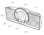
도 1은 본 발명의 일 실시예에 따른 스피커 출력용 도킹 장치의 외부 사시도이고,
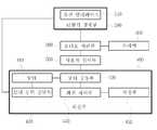
도 2는 도 1의 스피커 출력용 도킹 장치의 기능 블록도이고,
도 3은 도 1의 스피커 출력용 도킹 장치에 통신 단말기가 장착된 후 회전하는 상태를 나타낸 도면이고,
도 4는 도 1의 스피커 출력용 도킹 장치의 모터 및 동력 전달부의 개략 구성을 나타낸 도면이고,
도 5는 도 1의 스피커 출력용 도킹 장치가 삽입 장착된 통신 단말기를 90도만 회전하도록 하기 필요한 회전 스토퍼를 나타낸 도면이고,
도 6은 도 1의 스피커 출력용 도킹 장치의 저장부에 저장된 비선형 속도 테이블의 데이터 특성의 일 예를 나타낸 도면이고,
도 7은 도 1의 스피커 출력용 도킹 장치의 단말기 장착부의 단면을 나타낸 도면이다.1 is an external perspective view of a speaker output docking apparatus according to an embodiment of the present invention,
Fig. 2 is a functional block diagram of the docking device for speaker output of Fig. 1,
FIG. 3 is a view illustrating a state in which the communication terminal is mounted on the speaker output docking apparatus of FIG. 1 and then rotated.
4 is a view showing a schematic configuration of a motor and a power transmitting portion of the docking device for speaker output of Fig. 1,
FIG. 5 is a view showing a rotation stopper required to rotate the communication terminal inserted with the docking device for speaker output of FIG. 1 only by 90 degrees,
FIG. 6 is a diagram illustrating an example of data characteristics of a nonlinear velocity table stored in a storage unit of the docking device for speaker output of FIG. 1,
7 is a cross-sectional view of the terminal mounting portion of the docking device for speaker output of FIG.
이하에서는 첨부도면을 참조하여 본 발명에 대해 상세히 설명한다.Hereinafter, the present invention will be described in detail with reference to the accompanying drawings.
도 1은 본 발명의 일 실시예에 따른 스피커 출력용 도킹 장치의 외관을 나타낸 것이고, 도 2는 그 스피커 출력용 도킹 장치의 기능 블록을 나타낸 것이다.FIG. 1 shows an appearance of a docking device for speaker output according to an embodiment of the present invention, and FIG. 2 shows a functional block diagram of the docking device for speaker output.
이러한 스피커 출력용 도킹 장치에는 소정의 통신 단말기가 삽입 장착된 상태에서 회전할 수 있는데, 예를 들어 도 3(a)와 같이 스피커 출력용 도킹 장치에 세로 방향으로 통신 단말기가 삽입 장착된 상태에서 내부에 구비된 모터(410)의 회전에 따라 도 3(b)와 같이 삽입 장착된 통신 단말기가 후술하는 단말기 장착부(100)와 함께 90방향 즉, 가로 방향으로 회전할 수 있는 것이다.For example, as shown in FIG. 3 (a), the docking device for speaker output can be rotated in a state where a communication terminal is inserted and mounted in the docking device for speaker output. The communication terminal inserted and mounted as shown in FIG. 3 (b) can rotate in the 90 direction, that is, the horizontal direction together with the
스피커 출력용 도킹 장치의 구성요소의 기능에 대해서 먼저 설명하면 다음과 같다.The functions of the components of the docking device for speaker output will be described first.
사용자 입력부(500)는 사용자가 조작하는 명령을 수신하는 기능을 수행하는데, 예를 들어 적어도 하나의 누름 버튼(510)을 포함하여 구성될 수 있고, 또는 리모콘 수신부를 포함하여 구성될 수 있다.The
즉, 사용자는 사용자 입력부(500)의 조작을 통해 후술하는 바와 같이 본 발명에 따른 스피커 출력용 도킹 장치의 각종 기능, 예를 들어 입력되는 오디오 신호를 출력하는 기능, 삽입 장착된 통신 단말기가 회전하도록 하는 기능 등을 수행할 수 있다.That is, the user operates various functions of the docking device for speaker output according to the present invention, for example, a function of outputting an input audio signal, a function of causing the inserted communication terminal to rotate Function and so on.
단말기 장착부(100)는 단말기 유선 인터페이스(110)를 포함하고 앞서 설명한 통신 단말기가 장착되고 회전 가능하게 구성된다.The
여기서 단말기 유선 인터페이스(110)는 삽입 장착되는 통신 단말기에 구비된 인터페이스와 직접 연결되는 인터페이스를 의미하는데, 예를 들어 USB(Universal Serial Bus), 마이크로 USB 등과 같이 소정의 통신 프로토콜에 따른 통신이 이루어지도록 구성될 수 있다.Here, the terminal
즉, 통신 단말기는 스피커 출력용 도킹 장치의 단말기 장착부(100)에 삽입 장착됨과 동시에 그 단말기 장착부(100) 안쪽에 구비된 유선 인터페이스(110)와 결합되는 것이다. 이에 따라 통신 단말기에서 생성되는 오디오 신호는 해당 유선 인터페이스(110)를 통해 스피커 출력용 도킹 장치 내부로 입력될 수 있는 것이다.That is, the communication terminal is inserted into the
스피커(200)는 통신 단말기로부터 입력되는 오디오 신호를 출력하는 것으로서, 특히 후술하는 오디오 처리부(300)로부터 전달되는 오디오 신호를 출력하여 사용자들이 들을 수 있도록 한다. 스피커(200)의 기능 및 구성은 기 공지된 기술에 해당하므로 보다 상세한 설명을 생략한다.The
오디오 처리부(300)는 유선 인터페이스(110)를 통해 통신 단말기로부터 입력되는 오디오 신호를 처리하여 스피커(200)로 전송하는 기능을 수행한다. 이러한 오디오 처리부(300)에는 입력된 오디오 신호를 증폭하거나 잡음을 필터링 하는 기능 등을 수행할 수도 있다.The
회전부(400)는 단말기 장착부(100)를 회전시키는 기능을 수행한다. 회전부(400)가 단말기 장착부(100)를 회전시키게 되면 단말기 장착부(100)에 삽입 장착된 통신 단말기가 함께 회전하게 되고, 통신 단말기의 가로 방향 모드와 세로 방향 모드를 모두 이용할 수 있게 된다. 여기서 통신 단말기의 가로 방향 모드는 통신 단말기의 디스플레이부가 직사각형상으로 이루어진 경우 직사각형의 긴 변이 가로에 위치한 상태에서 동영상 또는 이미지 등이 가로 방향의 화면에 맞게 표시되는 모드를 의미하고, 세로 방향 모드는 직사각형의 긴 변이 세로에 위치한 상태에서 동영상 또는 이미지 등이 세로 방향의 화면에 맞게 표시되는 모드를 의미한다.The
참고로 도 3(a)는 통신 단말기가 세로 방향 모드로 동작하고 있는 상태를 나타내고, 도 3(b)는 통신 단말기가 가로 방향 모드로 동작하고 있는 상태를 나타낸다.3 (a) shows a state in which the communication terminal operates in the vertical direction mode, and FIG. 3 (b) shows a state in which the communication terminal operates in the horizontal direction mode.
이러한 회전부(400)는 모터(410), 모터 구동부(420), 모터 동력 전달부(430), 저장부(450)와, 회전 제어부(440)를 포함하여 구성될 수 있다.The
먼저 모터(410)는 전기적인 신호에 따라 회전운동을 발생시키는 장치로서, 예를 들어 직류 또는 교류 신호에 따라 중심축에 구비된 샤프트를 회전시킬 수 있다. 모터(410)의 구성 및 기능은 기 공지된 기술에 해당하므로 보다 상세한 설명을 생략한다.First, the
모터 구동부(420)는 모터(410)와 연결되어 소정의 제어 신호에 따라 실제 모터(410)를 구동시키는 기능을 수행하는 것으로서, 예를 들어 직류 신호를 교류 신호로 변환시키는 인버터부를 포함하여 구성될 수 있다.The
모터 동력 전달부(430)는 모터(410)의 회전력을 단말기 장착부(100)에 전달하여 모터(410)의 회전에 따라 단말기 장착부(100)가 회전할 수 있도록 한다. 이러한 모터 동력 전달부(430)는 적어도 하나의 기어를 포함하는 기억박스와 동력 전달용 팬밸트 등을 포함하여 구성될 수 있다.The motor
모터(410)와 모터 동력 전달부(430)의 일 예는 도 4에 도시된 바와 같다.One example of the
동 도면에 도시된 바와 같이 모터(410)의 중심 축 샤프트의 회전은 팬밸트와 복수 개의 기어(430)를 경유하여 결국 단말기 장착부(100)에 직접 연결된 회전판(170)까지 전달될 수 있다.The rotation of the central axis shaft of the
다른 예로써 기어 박스 없이 모터(410)의 중심축 샤프트가 직접 단말기 장착부(100)의 중심과 연결되도록 구성될 수도 있는데, 이때 필요한 체결구들은 모터(410)를 이용하여 소정의 물체를 회전시키는 기술 분야에서 기 공지된 것이므로 보다 상세한 설명을 생략한다.As another example, the center shaft of the
저장부(450)에는 비선형 속도 테이블이 저장되어 있다.The
여기서 비선형 속도 테이블은 모터(410)의 속도를 비선형적으로 제어하기 위해 구비한 테이블인데, 예를 들어 단말기 장착부(100)가 일정한 속도로 회전하도록 제어하기 위해 구비한 테이블이다. 비선형 속도 테이블의 이용에 관한 보다 상세한 설명은 후술토록 한다.Here, the nonlinear velocity table is a table provided for nonlinearly controlling the speed of the
회전 제어부(440)는 저장부(450)에 저장된 비선형 속도 테이블을 이용하여 모터 구동부(420)를 제어하는 기능을 수행한다. 예를 들어 회전 제어부(440)는 PWM(Pulse Width Modulation) 신호를 모터 구동부(420)에 인가하여 모터(410)의 회전 속도를 제어할 수 있는데, 저장부(450)에 저장된 비선형 속도 테이블을 이용하여 시간에 따라 PWM 신호의 듀티비를 가변시킬 수 있는 것이다.The
예를 들어 저장부(450)에 저장된 비선형 속도 테이블에 포함된 각 데이터가 도 6에 도시된 그래프를 만족하는 데이터인 경우, 회전 제어부(440)는 시간 흐름에 따라 모터(410) 제어를 위한 PWM 신호의 듀티비를 줄이게 된다.For example, when each data included in the nonlinear velocity table stored in the
참고로 회전 제어부(440)는 모터(410)의 회전 방향에 따라 서로 구별되는 비선형 속도 테이블이 이용될 수 있다.For reference, the
회전 제어부(440)가 모터(410)의 구동을 위해 동일한 듀티비의 PWM 신호를 인가한다 하더라도 단말기 장착부(100)에 통신 단말기가 장착된 상태에서 회전하는 경우에는 회전 각도가 증가함에 따라 통신 단말기의 무게로 인해 회전 속도가 변하게 된다.Even if the
예를 들어 도 3(a)와 같이 통신 단말기가 단말기 장착부(100)에 삽입 장착된 상태에서 도 3(b)와 같이 반시계 방향으로 회전하는 경우 회전 제어부(440)가 동일한 듀티비의 PWM 신호를 인가한다 하더라도 회전속도는 점차 증가하게 된다. 이는 도 3(b)의 상태에서 도 3(a)의 상태로 시계방향으로 회전하는 경우에도 마찬가지이다. 이에 반해 본 발명과 같이 비선형 속도 테이블을 이용하여 모터를 제어하게 되면 이러한 문제점들은 해소될 수 있다.For example, when the communication terminal is inserted into the
상술한 저장부(450)에 저장된 비선형 속도 테이블에 포함된 데이터는 회전 제어부(440)의 교류 제어 신호(일 예로 상술한 PWM 신호)의 주파수가 가청주파수(20Hz~20KHz)를 피하도록 설정된 값일 수 있다.The data included in the nonlinear velocity table stored in the
예를 들어 회전 제어부(440)는 비선형 속도 테이블의 데이터를 이용하여 50KHz 근방의 주파수를 갖는 PWM 신호를 모터 구동부(420)에 인가할 수 있는 것이다.For example, the
이에 따라 회전 제어부(440)의 제어 신호에 의해 사람 귀에 들리는 잡음이 발생하는 것을 방지할 수 있다.Accordingly, it is possible to prevent the noise heard by the human ear from being generated by the control signal of the
도 3(a) 및 도 3(b)와 같이 90도 각도로 회전하여 멈추도록 하기 위해서 해당 각도만큼 회전시 단말기 장착부(100)의 회전이 멈추도록 하는 회전 스토퍼(180)가 단말기 장착부(100)와 직접 연결된 회전판(170)에 구비될 수 있는데, 이처럼 빠른 속도로 회전하는 물체가 회전 스토퍼에 의해 강제로 멈추게 되는 경우 큰 소음이 발생하고, 스토퍼에 무리한 충격을 가해 회전 스토퍼가 손상될 염려가 있다.(회전 스토퍼(180)와 그 회전 스토퍼(180)를 일정한 위치에 멈추도록 하는 고정체(190)의 일 예는 도 5에 도시되었다. 도 5는 스피커 출력용 도킹 장치의 내부로서 특히 단말기 장착부(100)의 뒷면을 나타내고 있다.)A
이러한 문제를 해결하기 위해 회전 제어부(440)는 상술한 바와 같이 저장부(450)에 저장된 비선형 속도 테이블을 이용하여 모터(410)의 회전을 제어하는 것이다. 특히 회전 제어부(440)는 비선형 속도 테이블을 이용하여 통신 단말기가 장착된 단말기 장착부(100)가 동일한 속도로 회전하도록 제어할 수 있다.In order to solve this problem, the
또한, 회전 제어부(440)는 기 설정된 시간동안 단말기 장착부(100)가 기 설정된 위치까지 회전하지 않았다고 판단하는 경우 모터(410)가 정지하도록 모터 구동부(420)를 제어할 수 있다. 이는 모터(410)가 외력 등에 의해 정상적인 속도로 회전하지 않는 경우 모터(410)에 무리가 가서 파손되는 것을 방지하기 위함이다.The
한편, 앞서 설명한 단말기 장착부(100)의 구조에 대해 보다 상세히 설명하면 다음과 같다. 참고로 단말기 장착부(100)의 구조는 도 7에 자세히 나타나 있다.The structure of the
단말기 장착부(100)는 세로방향으로 설치되는 베이스(120)와, 이 베이스(120)의 아랫부분에 형성되어 통신 단말기의 하부를 수납하는 수납부(130)를 포함하여 구성된다.The
베이스(120)는 단말기 장착부(100)에 장착되는 통신 단말기의 뒷면과 마주보는 면을 의미한다.The
이 베이스(120)에는 단말기 장착부(100)가 가로방향으로 회전한 경우 그 단말기 장착부(100)에 장착된 단말기를 아랫방향에서 지지하는 가로 방향 지지부(150)가 돌출 형성될 수 있다. 도 3(b)를 참조하면 가로 방향 지지부(150)의 이러한 기능을 확인할 수 있다. 즉, 도 3(b)에는 통신 단말기의 하부가 수납부(130)에 수납된 후 회전한 상태를 나타내고 있고, 이때 가로 방향 지지부(150)가 통신 단말기를 아랫방향에서 지지하고 있다.In the
수납부(130)는 유선 인터페이스(110)를 포함하고 있는데, 여기서 유선 인터페이스(110)는 일 예로 마이크로 USB(Universal Serial Bus)일 수 있는데, 본 발명이 이에 한정되는 것은 아니다.The
수납부(130)는 삽입된 통신 단말기의 하단 앞면과 닿는 앞면 지지부(131)와 통신 단말기의 하단 측면과 닿는 측면 지지부(132)를 포함하여 구성될 수 있다.The
여기서 측면 지지부(132)의 통신 단말기 삽입 시작부분은 곡면으로 이루어질 수 있다. 이는 삽입부에 통신 단말기를 삽입하는 경우 통신 단말기의 표면 손상을 방지하고 쉽게 삽입 공간으로 삽입되도록 하기 위함이다.Here, the communication terminal insertion start portion of the
또한 베이스(120)에는 통신 단말기가 수납부(130)에 삽입될 때 해당 통신 단말기를 앞으로 밀어 견고한 장착이 이루어지도록 하고 삽입시의 마찰을 최소화시키는 뒷면 지지부(140)가 돌출 형성된다. 따라서 뒷면 지지부(140)는 수납부(130)와 근접한 위치에 형성됨이 바람직하다.Further, a back
도 7(c)를 참조하면 뒷면 지지부(140)는 좌측과 우측에 각각 한 개씩 구비되어 있고, 베이스(120) 면으로부터 소정의 크기만큼 돌출 형성되어 있음을 알 수 있다. 따라서 삽입부에 통신 단말기를 삽입한 경우 통신 단말기 뒷면은 뒷면 지지부(140)에 닿아 있게 되는 것이다.Referring to FIG. 7 (c), it is understood that the
즉, 통신 단말기는 뒤쪽으로는 뒷면 지지부(140)와 맞닿아 있고, 앞쪽으로는 상술한 앞면 지지부(131)에 맞닿아 있어 견고하게 장착될 수 있는 것이다.That is, the communication terminal is in contact with the rear
뒷면 지지부(140)가 형성되지 않은 경우에는 삽입시 통신 단말기가 베이스(120) 전체 면과 맞닿으면서 삽입되므로 높은 삽입 마찰이 발생하여 삽입이 용이하지 않다. 뒷면 지지부(140)가 형성됨으로써 삽입 장착된 통신 단말기의 뒷면 대부분은 베이스(120) 면과 닿지 않을 수 있어서 통신 단말기의 착탈이 용이해진다.In the case where the
한편, 베이스(120) 중앙부에는 단말기 장착부(100)에 장착된 단말기의 뒤쪽 방향 움직임을 방지하는 유격 줄임부(160)가 돌출 형성될 수 있다.The base 120 may protrude from the center of the base 120 to prevent the terminal mounted on the
즉, 상술한 바와 같이 삽입 장착된 통신 단말기는 베이스(120) 면과 닿지 않아 소정의 유격이 발생하므로 외부의 충격에 의해 쉽게 흔들릴 수 있다. 이를 방지하기 위해 베이스(120) 중앙부에 소정의 돌출 부위를 형성함으로써 통신 단말기가 뒤로 흔들릴 때 그 흔들리는 폭을 최소화시킬 수 있다.That is, as described above, since the inserted communication terminal does not touch the
유격 줄임부(160)의 돌출 높이는 뒷면 지지부(140)의 돌출 높이보다 조금 작은게 바람직한데, 이는 통신 단말기의 삽입시에는 유격 줄임부(160)에 닿지 않도록 하면서도, 외부 충격 등에 의해 통신 단말기가 흔들릴 때만 유격 줄임부(160)에 닿도록 하기 위함이다.It is preferable that the protrusion height of the
상술한 구성에 따라 본원발명은 삽입 장착되는 통신 단말기의 가로 방향 모드와 세로 방향 모드를 모두 이용할 수 있게 하면서도, 그 삽입 장착된 상태가 견고하게 이루어지도록 할 수 있다.According to the above-described configuration, the present invention can use both the horizontal mode and the vertical mode of the inserted communication terminal, and the inserted state can be firmly established.
또한 삽입된 상태에서의 유격이 최소화되도록 할 수 있으며, 더 나아가 통신 단말기의 회전시 일정한 회전 속도를 갖도록 할 수 있다.Also, it is possible to minimize the clearance in the inserted state, and further, to have a constant rotation speed when the communication terminal is rotated.
이상 설명한 바와 같이 본 발명에 따르면, 스피커 출력용 도킹 장치에 장착된 통신 단말기를 그 장착된 상태에서 회전하여 가로 방향 모드와 세로 방향 모드를 모두 이용할 수 있도록 한다.As described above, according to the present invention, the communication terminal mounted on the docking device for speaker output can be rotated in the mounted state so that both the horizontal mode and the vertical mode can be used.
또한 통신 단말기가 스피커 출력용 도킹 장치에 삽입 장착되는 과정의 마찰 발생을 최소화하고, 장착된 이후에는 외부 충격 등이 발생한 경우 삽입 장착된 통신 단말기가 움직임을 최소화할 수 있다.In addition, it is possible to minimize the occurrence of friction in the process of inserting the communication terminal into the docking device for speaker output, and minimizing the movement of the inserted communication terminal when an external shock or the like occurs after being mounted.
한편, 본 발명은 상기한 특정 실시예에 한정되는 것이 아니라 본 발명의 요지를 벗어나지 않는 범위 내에서 여러 가지로 변형 및 수정하여 실시할 수 있는 것이다. 이러한 변형 및 수정이 첨부되는 특허청구범위에 속한다면 본 발명에 포함된다는 것은 자명할 것이다.While the present invention has been particularly shown and described with reference to exemplary embodiments thereof, it is to be understood that the invention is not limited to the disclosed exemplary embodiments, but, on the contrary, is intended to cover various modifications and equivalent arrangements included within the spirit and scope of the invention. It is to be understood that such variations and modifications are intended to be included in the scope of the appended claims.
100 : 단말기 장착부 200 : 스피커
300 : 오디오 처리부 400 : 회전부
500 : 사용자 입력부 110 : 유선 인터페이스
120 : 베이스 130 : 수납부
131 : 앞면 지지부 132 : 측면 지지부
140 : 뒷면 지지부 150 : 가로방향 지지부
160 : 유격 줄임부 410 : 모터
420 : 모터 구동부 430 : 모터 동력 전달부
440 : 회전 제어부 450 : 저장부100: terminal mounting portion 200: speaker
300: audio processing unit 400:
500: user input unit 110: wired interface
120: base 130:
131: front support part 132: side support part
140: backside support part 150: transverse support part
160: Stripping block 410: Motor
420: motor driving part 430: motor power transmission part
440: rotation control unit 450:
Claims (6)
Translated fromKorean스피커와;
상기 유선 인터페이스를 통해 입력되는 오디오 신호를 처리하여 상기 스피커로 전송하는 오디오 처리부와;
상기 단말기 장착부를 회전시키는 회전부를 포함하여 구성되고,
상기 단말기 장착부는, 세로방향으로 설치되는 베이스와, 상기 유선 인터페이스를 포함하고 상기 베이스의 아랫 부분에 형성되어 상기 단말기의 하부를 수납하는 수납부를 포함하여 구성되고,
상기 베이스에는 상기 단말기가 상기 수납부에 삽입될 때 상기 단말기를 앞으로 밀어 견고한 장착이 이루어지도록 하고 삽입시의 마찰을 최소화시키는 뒷면 지지부와, 상기 단말기 장착부가 가로방향으로 회전한 경우 상기 단말기 장착부에 장착된 단말기를 아랫방향에서 지지하는 가로방향 지지부가 돌출 형성되고,
상기 회전부는 모터, 모터 구동부, 비선형 속도 테이블이 저장된 저장부, 상기 모터의 회전력을 상기 단말기 장착부에 전달하는 모터 동력 전달부와, 회전 제어부를 포함하여 구성되고,
상기 회전 제어부는 상기 저장부에 저장된 비선형 속도 테이블을 이용하여 상기 모터가 일정한 속도로 회전하도록 상기 모터 구동부를 제어하는 것을 특징으로 하는 스피커 출력용 도킹 장치.A terminal mounting unit including a wired interface and configured to be rotatable;
A speaker;
An audio processor for processing an audio signal input through the wired interface and transmitting the audio signal to the speaker;
And a rotation part for rotating the terminal mounting part,
The terminal mounting portion includes a base installed in a longitudinal direction and a housing portion including the wired interface and formed at a lower portion of the base to receive a lower portion of the terminal,
The base includes a rear supporting portion for pushing the terminal forward when the terminal is inserted into the receiving portion and minimizing the friction at the time of insertion, and a rear supporting portion for mounting the terminal mounting portion on the terminal mounting portion A transverse support portion for supporting the terminal in a downward direction is protruded,
The rotation unit includes a motor, a motor driving unit, a storage unit storing a nonlinear velocity table, a motor power transmission unit transmitting rotation force of the motor to the terminal mounting unit, and a rotation control unit,
Wherein the rotation control unit controls the motor driving unit so that the motor rotates at a constant speed using the nonlinear velocity table stored in the storage unit.
상기 베이스 중앙부에는 상기 단말기 장착부에 장착된 단말기의 뒤쪽 방향 움직임을 방지하는 유격 줄임부가 돌출 형성된 것을 특징으로 하는 스피커 출력용 도킹 장치.The method according to claim 1,
And a protruding portion for preventing movement of the terminal mounted on the terminal mounting portion is prevented from protruding toward the rear of the base.
상기 수납부는 삽입된 상기 단말기의 하단 앞면과 닿는 앞면 지지부와; 상기 단말기의 하단 측면과 닿는 측면 지지부를 포함하여 구성되고,
상기 측면 지지부의 상기 단말기 삽입 시작부분은 곡면으로 이루어진 것을 특징으로 하는 스피커 출력용 도킹 장치.The method according to claim 1,
Wherein the housing part comprises: a front surface supporting part contacting the lower front surface of the inserted terminal; And a side support portion contacting the lower side surface of the terminal,
Wherein the terminal insertion start portion of the side support portion is formed of a curved surface.
상기 회전 제어부는 기 설정된 시간동안 상기 단말기 장착부가 기 설정된 위치까지 회전하지 않았다고 판단하는 경우 상기 모터가 정지하도록 상기 모터 구동부를 제어하는 것을 특징으로 하는 스피커 출력용 도킹 장치.The method according to claim 1,
Wherein the rotation control unit controls the motor driving unit to stop the motor when the terminal mounting unit determines that the terminal mounting unit has not rotated to a predetermined position for a predetermined time.
상기 회전 제어부는 교류 제어 신호를 상기 모터 구동부에 인가하여 모터의 회전을 제어하고,
상기 저장부에 저장된 비선형 속도 테이블에 포함된 데이터는 상기 회전 제어부의 교류 제어 신호의 주파수가 가청주파수를 피하도록 설정된 값인 것을 특징으로 하는 스피커 출력용 도킹 장치.The method according to claim 1,
The rotation control unit applies an AC control signal to the motor driving unit to control the rotation of the motor,
Wherein the data included in the nonlinear velocity table stored in the storage unit is a value set such that the frequency of the AC control signal of the rotation control unit avoids an audible frequency.
Priority Applications (1)
| Application Number | Priority Date | Filing Date | Title |
|---|---|---|---|
| KR20130088869AKR101489083B1 (en) | 2013-07-26 | 2013-07-26 | Docking apparatus for speaker output |
Applications Claiming Priority (1)
| Application Number | Priority Date | Filing Date | Title |
|---|---|---|---|
| KR20130088869AKR101489083B1 (en) | 2013-07-26 | 2013-07-26 | Docking apparatus for speaker output |
Publications (1)
| Publication Number | Publication Date |
|---|---|
| KR101489083B1true KR101489083B1 (en) | 2015-02-02 |
Family
ID=52590115
Family Applications (1)
| Application Number | Title | Priority Date | Filing Date |
|---|---|---|---|
| KR20130088869AActiveKR101489083B1 (en) | 2013-07-26 | 2013-07-26 | Docking apparatus for speaker output |
Country Status (1)
| Country | Link |
|---|---|
| KR (1) | KR101489083B1 (en) |
Citations (3)
| Publication number | Priority date | Publication date | Assignee | Title |
|---|---|---|---|---|
| KR970049279A (en)* | 1995-12-22 | 1997-07-29 | 김광호 | Portable computer removable device in the docking station |
| JP2001128485A (en)* | 1999-10-27 | 2001-05-11 | Mitsubishi Electric Corp | Motor system, air conditioner equipped with the motor system, and method of starting motor |
| KR20110073501A (en)* | 2008-09-25 | 2011-06-29 | 코비 일렉트로닉스 코포레이션 | Docking Station with Rotating Mechanism |
- 2013
- 2013-07-26KRKR20130088869Apatent/KR101489083B1/enactiveActive
Patent Citations (3)
| Publication number | Priority date | Publication date | Assignee | Title |
|---|---|---|---|---|
| KR970049279A (en)* | 1995-12-22 | 1997-07-29 | 김광호 | Portable computer removable device in the docking station |
| JP2001128485A (en)* | 1999-10-27 | 2001-05-11 | Mitsubishi Electric Corp | Motor system, air conditioner equipped with the motor system, and method of starting motor |
| KR20110073501A (en)* | 2008-09-25 | 2011-06-29 | 코비 일렉트로닉스 코포레이션 | Docking Station with Rotating Mechanism |
Similar Documents
| Publication | Publication Date | Title |
|---|---|---|
| US20070230723A1 (en) | Portable media delivery system | |
| AU2013372185B2 (en) | Computer apparatus for use by senior citizens | |
| US9201458B2 (en) | Nudge notification via shifting device battery | |
| EP3769181B1 (en) | Expandable enclosure for electronic device resonance box | |
| CN108769311A (en) | A kind of method for controlling mobile terminal and mobile terminal | |
| US20090304217A1 (en) | Apparatus and method for using a portable media unit | |
| CN111224440A (en) | Wireless charging stand and electronic equipment | |
| CN105554200A (en) | Mobile terminal | |
| CN102165856A (en) | Docking station with rotation mechanism | |
| CN106170029B (en) | Stereo mobile terminal | |
| US9918152B2 (en) | Peripheral audio output device | |
| CN205545424U (en) | Mobile terminal | |
| KR20140082154A (en) | Expandable auxiliary apparatus for portable device with device holder | |
| CN109862459B (en) | TWS earphone device | |
| KR101250933B1 (en) | Charging and correspondence holder of portable electronic equipment | |
| JP2023054816A (en) | Speaker box assembly, display device, audio output method, and audio output device | |
| KR101489083B1 (en) | Docking apparatus for speaker output | |
| CN111885466B (en) | Speaker structure and electronic equipment | |
| WO2012071607A1 (en) | Entertainment system | |
| WO2012155399A1 (en) | Multimedia player and wireless earphone charged by the same | |
| CN213586148U (en) | Speaker components, display equipment | |
| CN113572878B (en) | Electronic device, control method and control device thereof, and readable storage medium | |
| WO2023020112A1 (en) | Audio playback device, terminal, and audio control method | |
| CN110225197B (en) | Connection processing method, terminal and electronic equipment | |
| KR101319685B1 (en) | A apparatus for holding and fixing mobile phone |
Legal Events
| Date | Code | Title | Description |
|---|---|---|---|
| PA0109 | Patent application | Patent event code:PA01091R01D Comment text:Patent Application Patent event date:20130726 | |
| PA0201 | Request for examination | ||
| PE0902 | Notice of grounds for rejection | Comment text:Notification of reason for refusal Patent event date:20140612 Patent event code:PE09021S01D | |
| E701 | Decision to grant or registration of patent right | ||
| PE0701 | Decision of registration | Patent event code:PE07011S01D Comment text:Decision to Grant Registration Patent event date:20150116 | |
| GRNT | Written decision to grant | ||
| PR0701 | Registration of establishment | Comment text:Registration of Establishment Patent event date:20150127 Patent event code:PR07011E01D | |
| PR1002 | Payment of registration fee | Payment date:20150127 End annual number:3 Start annual number:1 | |
| PG1601 | Publication of registration | ||
| FPAY | Annual fee payment | Payment date:20171208 Year of fee payment:6 | |
| PR1001 | Payment of annual fee | Payment date:20171208 Start annual number:4 End annual number:6 | |
| PR1001 | Payment of annual fee | Payment date:20231207 Start annual number:10 End annual number:10 | |
| PR1001 | Payment of annual fee | Payment date:20241209 Start annual number:11 End annual number:11 |