KR101487778B1 - Sensing system and moving robot having the same - Google Patents
Sensing system and moving robot having the sameDownload PDFInfo
- Publication number
- KR101487778B1 KR101487778B1KR20100043914AKR20100043914AKR101487778B1KR 101487778 B1KR101487778 B1KR 101487778B1KR 20100043914 AKR20100043914 AKR 20100043914AKR 20100043914 AKR20100043914 AKR 20100043914AKR 101487778 B1KR101487778 B1KR 101487778B1
- Authority
- KR
- South Korea
- Prior art keywords
- light
- light guide
- guide
- receiving
- main body
- Prior art date
- Legal status (The legal status is an assumption and is not a legal conclusion. Google has not performed a legal analysis and makes no representation as to the accuracy of the status listed.)
- Expired - Fee Related
Links
Images


Classifications
- G—PHYSICS
- G01—MEASURING; TESTING
- G01S—RADIO DIRECTION-FINDING; RADIO NAVIGATION; DETERMINING DISTANCE OR VELOCITY BY USE OF RADIO WAVES; LOCATING OR PRESENCE-DETECTING BY USE OF THE REFLECTION OR RERADIATION OF RADIO WAVES; ANALOGOUS ARRANGEMENTS USING OTHER WAVES
- G01S7/00—Details of systems according to groups G01S13/00, G01S15/00, G01S17/00
- G01S7/48—Details of systems according to groups G01S13/00, G01S15/00, G01S17/00 of systems according to group G01S17/00
- G01S7/481—Constructional features, e.g. arrangements of optical elements
- G01S7/4814—Constructional features, e.g. arrangements of optical elements of transmitters alone
- B—PERFORMING OPERATIONS; TRANSPORTING
- B25—HAND TOOLS; PORTABLE POWER-DRIVEN TOOLS; MANIPULATORS
- B25J—MANIPULATORS; CHAMBERS PROVIDED WITH MANIPULATION DEVICES
- B25J19/00—Accessories fitted to manipulators, e.g. for monitoring, for viewing; Safety devices combined with or specially adapted for use in connection with manipulators
- B25J19/02—Sensing devices
- B—PERFORMING OPERATIONS; TRANSPORTING
- B25—HAND TOOLS; PORTABLE POWER-DRIVEN TOOLS; MANIPULATORS
- B25J—MANIPULATORS; CHAMBERS PROVIDED WITH MANIPULATION DEVICES
- B25J5/00—Manipulators mounted on wheels or on carriages
- B25J5/007—Manipulators mounted on wheels or on carriages mounted on wheels
- G—PHYSICS
- G01—MEASURING; TESTING
- G01S—RADIO DIRECTION-FINDING; RADIO NAVIGATION; DETERMINING DISTANCE OR VELOCITY BY USE OF RADIO WAVES; LOCATING OR PRESENCE-DETECTING BY USE OF THE REFLECTION OR RERADIATION OF RADIO WAVES; ANALOGOUS ARRANGEMENTS USING OTHER WAVES
- G01S17/00—Systems using the reflection or reradiation of electromagnetic waves other than radio waves, e.g. lidar systems
- G01S17/88—Lidar systems specially adapted for specific applications
- G01S17/93—Lidar systems specially adapted for specific applications for anti-collision purposes
- G01S17/931—Lidar systems specially adapted for specific applications for anti-collision purposes of land vehicles
- G—PHYSICS
- G05—CONTROLLING; REGULATING
- G05D—SYSTEMS FOR CONTROLLING OR REGULATING NON-ELECTRIC VARIABLES
- G05D1/00—Control of position, course, altitude or attitude of land, water, air or space vehicles, e.g. using automatic pilots
- G05D1/02—Control of position or course in two dimensions
- G05D1/021—Control of position or course in two dimensions specially adapted to land vehicles
- G05D1/0227—Control of position or course in two dimensions specially adapted to land vehicles using mechanical sensing means, e.g. for sensing treated area
- G—PHYSICS
- G05—CONTROLLING; REGULATING
- G05D—SYSTEMS FOR CONTROLLING OR REGULATING NON-ELECTRIC VARIABLES
- G05D1/00—Control of position, course, altitude or attitude of land, water, air or space vehicles, e.g. using automatic pilots
- G05D1/02—Control of position or course in two dimensions
- G05D1/021—Control of position or course in two dimensions specially adapted to land vehicles
- G05D1/0231—Control of position or course in two dimensions specially adapted to land vehicles using optical position detecting means
- G05D1/0238—Control of position or course in two dimensions specially adapted to land vehicles using optical position detecting means using obstacle or wall sensors
- A—HUMAN NECESSITIES
- A47—FURNITURE; DOMESTIC ARTICLES OR APPLIANCES; COFFEE MILLS; SPICE MILLS; SUCTION CLEANERS IN GENERAL
- A47L—DOMESTIC WASHING OR CLEANING; SUCTION CLEANERS IN GENERAL
- A47L2201/00—Robotic cleaning machines, i.e. with automatic control of the travelling movement or the cleaning operation
- A47L2201/04—Automatic control of the travelling movement; Automatic obstacle detection
Landscapes
- Engineering & Computer Science (AREA)
- Physics & Mathematics (AREA)
- General Physics & Mathematics (AREA)
- Radar, Positioning & Navigation (AREA)
- Remote Sensing (AREA)
- Computer Networks & Wireless Communication (AREA)
- Electromagnetism (AREA)
- Aviation & Aerospace Engineering (AREA)
- Automation & Control Theory (AREA)
- Robotics (AREA)
- Mechanical Engineering (AREA)
- Control Of Position, Course, Altitude, Or Attitude Of Moving Bodies (AREA)
- Manipulator (AREA)
- Geophysics And Detection Of Objects (AREA)
- Optical Radar Systems And Details Thereof (AREA)
Abstract
Translated fromKoreanDescription
Translated fromKorean본 발명은 주위의 인접한 물체를 감지하는 센싱 시스템과 이러한 센싱 시스템을 갖춘 이동 로봇에 관한 것이다.The present invention relates to a sensing system for sensing nearby objects and a mobile robot equipped with such a sensing system.
근래에는 청소 로봇과 같은 이동 로봇이 널리 보급되고 있는 추세인데, 이러한 이동 로봇은 이동 로봇이 이동하는 과정에서 벽이나 가구 등에 충돌하거나 바닥이 끝나는 지점에서 이동 로봇이 낙하하여 그 충격에 의해 손상될 수 있으므로 이동 로봇에는 이를 방지할 수 주위의 인접한 물체를 감지하는 센싱 시스템이 포함된다.In recent years, mobile robots such as cleaning robots have become widespread. Such mobile robots may collide with walls, furniture or the like during the movement of the mobile robots, Therefore, the mobile robot includes a sensing system for sensing an object adjacent thereto so as to prevent this.
센싱 시스템은 광 센서를 포함한 것으로, 광 센서는 광원을 내장하여 광을 방사하는 발광부와, 발광부에서 발광되었다가 인접한 물체에 의해 반사된 광을 수광하는 수광부를 포함하여, 발광부에서 조사된 광이 퍼지는 발광 영역과 수광부가 광을 수광할 수 있는 수광 영역이 겹쳐지는 부분이 광 센서가 물체를 감지할 수 있는 감지영역이 된다.The sensing system includes an optical sensor. The optical sensor includes a light emitting unit that emits light by incorporating a light source, and a light receiving unit that emits light from the light emitting unit and receives light reflected by an adjacent object, A portion where the light emitting region in which the light is spread and the light receiving region in which the light receiving portion is capable of receiving light becomes a sensing region in which the optical sensor can sense an object.
본 발명의 일 측면은 보다 넓은 영역으로 광을 방사할 수 있는 센싱 시스템 및 이를 갖춘 이동 로봇에 관한 것이다.One aspect of the present invention relates to a sensing system capable of emitting light in a wider area and a mobile robot equipped with the sensing system.
본 발명의 일 측면에 따른 센싱 시스템은 광을 발생시키는 광원과, 광원에서 발생한 광을 확산시켜 방사하는 광 가이드와, 광 가이드에서 방사되었다가 인접한 물체에 의해 반사된 광을 수광하는 수광센서를 포함한다.A sensing system according to an aspect of the present invention includes a light source that generates light, a light guide that emits light by diffusing light generated from the light source, and a light receiving sensor that receives light reflected from an adjacent object that is emitted from the light guide do.
또한 광 가이드는 일 방향으로 연장 형성되며, 광원은 광 가이드의 양 단면 중 적어도 어느 하나에 설치된다.Further, the light guide extends in one direction, and the light source is installed on at least one of both end faces of the light guide.
또한 광 가이드의 일측면에는 광 가이드 내로 입사된 광을 타측면을 향하여 반사하는 반사면이 마련된다.Further, on one side of the light guide, a reflecting surface for reflecting the light incident into the light guide toward the other side is provided.
또한 본 발명의 일 측면에 따른 이동 로봇은 본체와, 본체 주변의 물체를 감지하는 센싱 시스템을 포함하며, 센싱 시스템은 광을 발생시키는 광원과, 광원에서 발생한 광을 전달받아 확산시켜 방사하는 광 가이드와, 광 가이드에서 방사되었다가 인접한 물체에 의해 반사된 광을 수광하는 수광 센서를 포함한다.According to another aspect of the present invention, there is provided a mobile robot including a body and a sensing system for sensing an object around the body, wherein the sensing system includes a light source for generating light, a light guide for diffusing and radiating light generated by the light source, And a light receiving sensor for receiving the light emitted from the light guide and reflected by the adjacent object.
또한 본체는 원반 형상으로 형성되며, 광 가이드는 본체와 대응하도록 원주 방향으로 연장되어 본체의 전면측에 배치된다.The main body is formed in a disk shape, and the light guide extends in the circumferential direction so as to correspond to the main body, and is disposed on the front side of the main body.
또한 광원은 광 가이드의 양단 중 적어도 어느 하나에 설치되어 광 가이드의 양단면을 통해 광 가이드 내로 광을 입사한다.Further, the light source is provided on at least one of both ends of the light guide, and the light enters into the light guide through both end faces of the light guide.
또한 광 가이드의 후면에 마련되어 광 가이드 내로 입사된 광을 광 가이드의 전면측으로 반사하는 반사면을 포함한다.And a reflecting surface provided on the rear surface of the light guide for reflecting the light incident into the light guide to the front side of the light guide.
또한 광 가이드의 후면에는 반사면 형성을 위해 복수의 반사홈이 마련된다.Further, a plurality of reflection grooves are provided on the rear surface of the light guide for forming the reflection surface.
또한 광 가이드의 후방측에 배치되어 광 가이드의 후방측으로 방사된 광을 전방측으로 반사하는 반사부재를 더 포함한다.And a reflecting member disposed on the rear side of the light guide and reflecting the light emitted toward the rear side of the light guide toward the front side.
또한 수광 센서는 광 가이드의 상측에 배치되어 그 전방 하측으로부터의 광을 수광하여 장애물 감지 센서를 포함한다.Further, the light receiving sensor is disposed on the upper side of the light guide, and receives light from the front lower side thereof, and includes an obstacle detecting sensor.
또한 수광센서는 광 가이드에서 하측으로 방사되었다가 바닥에 의해 반사된 광을 수광하는 바닥 감지센서를 더 포함한다.The light receiving sensor further includes a floor detecting sensor which radiates downward from the light guide and receives light reflected by the floor.
또한 본체의 일측에 진퇴이동 가능하게 설치되며 광 가이드가 배치되는 범퍼를 더 포함하며, 수광 센서는 본체의 광 가이드 후방측에 배치되어 광 가이드의 후면으로부터 방사된 광을 수광하는 범퍼 감지센서를 포함한다.The light receiving sensor further includes a bumper detecting sensor disposed on a rear side of the light guide of the main body and receiving light emitted from the rear surface of the light guide. do.
또한 수광 센서는 광을 감지하는 감지부와, 감지부의 전방측에 배치되어 수광 센서의 수광영역을 결정하는 수광 렌즈를 포함한다.The light receiving sensor further includes a sensing unit for sensing light and a light receiving lens disposed on the front side of the sensing unit to determine a light receiving area of the light receiving sensor.
또한 수광 렌즈는 상하 방향의 수광영역과 좌우 방향의 수광영역은 서로 독립적으로 결정되는 비대칭 렌즈를 포함한다.The light receiving lens includes an asymmetric lens in which the light receiving region in the vertical direction and the light receiving region in the lateral direction are determined independently of each other.
또한 범퍼에는 광 가이드 및 장애물 센서와 대응하는 위치에 투명창이 마련된다.The bumper is also provided with a transparent window at a position corresponding to the light guide and the obstacle sensor.
상술한 바와 같이 광원에서 조사된 광이 광 가이드의 면을 통해 넓게 확산되어 방사되므로, 소수의 광원으로 넓은 영역에 광을 방사할 수 있다.As described above, since the light emitted from the light source diffuses widely through the surface of the light guide and is radiated, light can be emitted in a wide area with a small number of light sources.
또한, 센싱 시스템의 감지 영역이 수광 센서의 수광 영역이 대응하는 넓이로 대폭 증가되므로 인접한 물체를 감지할 수 없는 사각 영역을 대폭 감소시킬 수 있다.In addition, since the sensing area of the sensing system is greatly increased to a corresponding area of the light receiving area of the light receiving sensor, it is possible to greatly reduce a rectangular area in which an adjacent object can not be sensed.
도 1은 본 발명의 일 실시예에 따른 이동 로봇의 사시도이다.
도 2는 본 발명의 일 실시예에 따른 이동 로봇에 적용된 센싱 시스템의 사시도이다.
도 3과 도 4는 본 발명의 일 실시예에 따른 이동 로봇에 적용된 센싱 시스템의 개략도이다.
도 5는 본 발명의 일 실시예에 따른 이동 로봇에 적용된 수광 렌즈의 개략도이다.1 is a perspective view of a mobile robot according to an embodiment of the present invention.
2 is a perspective view of a sensing system applied to a mobile robot according to an embodiment of the present invention.
3 and 4 are schematic views of a sensing system applied to a mobile robot according to an embodiment of the present invention.
5 is a schematic view of a light receiving lens applied to a mobile robot according to an embodiment of the present invention.
이하에서는 본 발명에 따른 일 실시예에 따른 센싱 시스템 및 이를 갖춘 이동 로봇을 도면을 참조하여 상세히 설명한다.Hereinafter, a sensing system according to an embodiment of the present invention and a mobile robot equipped with the sensing system will be described in detail with reference to the drawings.
도 1에 도시한 바와 같이 본 실시예에서는 이동 로봇(100)은 본체(10)와, 본체(10)의 하면에 배치되어 본체(10)가 이동할 수 있도록 하는 바퀴(11, 12: 도 3 참조)와, 본체(10)의 전방측에 배치되는 범퍼(13) 등의 구성을 포함한다.1, the
본체(10)는 대략 원반 형상으로 형성되며, 바퀴(11, 12)는 본체(10)의 하부 양측에 나란히 배치된 한 쌍의 이동 바퀴(11)와, 본체(10)의 하부 전방측에 배치된 캐스터 바퀴(12)를 포함한다. 범퍼(13)는 본체(10)의 전방측에 전후 방향으로 진퇴이동 가능하게 설치되며, 탄성부재(미도시)를 통해 본체(10)에 탄성지지되어 이동 로봇(100)이 벽이나 가구 등과 같은 장애물과 불가피하게 충돌하게 되더라도 본체(10)에 전달되는 충격을 감소시킬 수 있도록 되어 있다.The
또한 이동 로봇(100)은 도 2, 3에 도시한 바와 같이 이동 로봇(100)이 이동하는 과정에서 본체(10) 주변의 벽이나 가구 또는 바닥 등의 주변 물체를 감지하여, 이동 로봇(100)이 충돌 또는 낙하하는 것을 방지하기 위한 센싱 시스템(20)을 포함한다.2 and 3, the
센싱 시스템(20)은 광을 발생시키는 광원(21)과, 광원에서 발생한 광을 전달받으며 전달된 광을 확산시켜 그 면을 통해 넓게 방사하는 광 가이드(22)와, 광 가이드(22)에서 방사되었다가 이동 로봇(100)에 인접한 물체에 의해 반사된 광을 수광하는 수광 센서(23A, 23B, 23C)를 포함한다.The
이와 같이 광이 광 가이드(22)의 면을 통해 방사되도록 하면, 소수의 광원(21)을 사용하여 넓은 영영에 광을 방사할 수 있게 되며, 그에 따라 설계자가 수광 센서(23A, 23B, 23C)의 위치를 다양하게 선정하여 설치할 수 있게 있다. 즉, 광 가이드(22) 내로 입사된 광은 광 가이드(22) 내부를 그 길이 방향으로 따라 이동하면서 점진적으로 분산되어 광 가이드(22)로부터 방사되는데, 이때 광은 광원(21)이 설치되어 있는 광 가이드(22)의 양단면을 제외한 나머지 면을 통해 전체적으로 방사된다.When the light is radiated through the surface of the
이와 같이 광원(21)에서 발생한 광이 광 가이드(22)를 주위로 전체적으로 분산되어 방사되도록 하면, 센싱 시스템(20)을 통해 인접 물체를 감지할 수 있는 감지 영역은 수광 센서(23A, 23B, 23C)가 광을 수광할 수 있는 수광 영역과 거의 대응하는 수준으로 넓어지게 되므로, 센싱 시스템의 감지 영역을 벗어나 이동 로봇(100)과 인접한 물체를 감지할 수 없는 사각 영역을 대폭 줄일 수 있을 뿐만 아니라 적은 수의 수광 센서(23A, 23B, 23C)를 통해서 이동 로봇(100) 인접 물체들을 효율적으로 감지할 수 있다.When the light emitted from the
광 가이드(22)는 일정 길이를 갖도록 일 방향으로 연장되며 그 양단에 광원(21)이 설치된다. 이러한 광 가이드(22)는 광을 안내할 수 있도록 투명 재질로 형성되는데, 광 가이드(22)를 형성하는 투명 재질로는 폴리 카보네이트(Poly Carbonate), 아크릴, 유리나 광섬유 등과 같이 투명하면서도 공기에 비해 상대적으로 밀도가 높은 여러 종류의 재질이 사용되어질 수 있다.The
따라서 광원(21)에서 발생한 광은 광 가이드(22)의 양단면을 통해 광 가이드(22) 내로 입사되고 광 가이드(22) 내로 입사된 광은 광 가이드(22)의 길이 방향으로 안내된다. 광 가이드(22)를 따라 이동하는 광은 광 가이드(22)와 공기의 경계면에서의 광의 입사각이나 광 가이드(22)와 공기의 밀도차 등의 여러 조건에 의해 일부분씩 점진적으로 광 가이드(22)로부터 출사되므로 이를 통해 광은 분산되어 광 가이드(22)의 전면, 후면 및 상, 하면을 통해 전체적으로 방사된다.The light generated in the
본 실시예에서 광 가이드(22)는 본체(10)의 전면 형상과 대응하도록 원주 방향으로 연장되며 범퍼(13)에 배치되어 범퍼(13)와 함께 진퇴이동하도록 되어 있다. 범퍼(13)에는 광 가이드(22)와 대응하는 위치에 광이 통과할 수 있도록 투명창(13a)이 마련되어 있다.The
광 가이드(22)의 후면에는 광 가이드(22) 내로 입사된 광을 전방측으로 반사할 수 있도록 하는 복수의 반사홈(22a)이 형성되어 반사홈(22a)이 마련된 광 가이드(22)의 후면이 광을 반사하는 반사면으로 작용한다. 본 실시예에서 반사홈(22a)들은 광 가이드(22) 내를 이동하는 광에 대하여 직각인 상하 방향으로 형성되어 광을 전방측으로 반사할 수 있다. 이때, 광 가이드(22)에는 그 후면에 반사홈(22a)이 형성되어 있으므로 광 가이드(22) 내로 입사된 광의 상당 부분은 광 가이드의 전방측으로 안내되나, 상술한 바와 같이 광 가이드는(22)는 투명 재질로 형성되어 있으므로 광 가이드(22) 내로 입사된 광은 광 가이드(22)의 후면에 마련된 복수의 반사홈(22a)들에 의해 반사되어 광 가이드(22)에서 방사된 광의 상당 부분은 광 가이드(22)의 전면을 통해 출사되어 장애물 감지를 위해 사용되며, 그 나머지는 광 가이드(22)의 하면이나 후면을 통해 하측이나 후방측으로 방사되어 바닥 감지나 범퍼 감지를 위해 사용된다.A plurality of
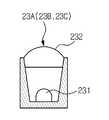
수광 센서(23A, 23B, 23C)는 도 5에 도시한 바와 같이 광을 감지하는 감지부(231)와, 감지부(231)의 전방측에 배치되어 수광 센서(23A, 23B, 23C)의 수광영역을 결정하는 수광 렌즈(232)를 포함한다. 본 실시예에서 수광 렌즈(232)는 상하 방향의 수광영역과 좌우 방향의 수광영역이 서로 독립적으로 결정되는 비대칭 렌즈로 이루어져 있는데, 이는 수광 센서(23A, 23B, 23C)가 설치되는 위치 및 수광 센서(23A, 23B, 23C)의 역할에 따라 감지해야 하는 상하 방향 수광 영역과 좌우 방향 수광 영역이 서로 상이하므로 이에 대응하기 위한 것이다.As shown in FIG. 5, the
또한 수광 센서(23A, 23B, 23C)는 도 3에 도시한 바와 같이 본체(10)의 전방측에 벽이나 가구 등과 같은 물체가 존재하는지의 여부를 감지하는 장애물 감지센서(23A)와, 이동 로봇(100)이 놓여진 곳의 바닥을 감지하는 바닥 감지센서(23B)와, 범퍼(13)의 위치를 감지하는 범퍼 감지센서(23C) 등을 포함한다.3, the
장애물 감지센서(23A)는 이동 로봇(100)의 전방측에 장애물이 존재하는지의 여부를 감지한다. 장애물 감지센서(23A)는 광 가이드(22)의 상측에 전방 하측을 향하여 경사지게 배치되어 전방 하측으로부터의 광을 수광하도록 되어 있는데, 이는 태양광이나 실내 조명에서 방사된 광이 장애물 감지센서(23A)에 수광되어 이동 로봇(100)이 오작동하는 것을 방지하기 위한 것이다. 본 실시예에서 장애물 감지센서(23A)는 도 2에 도시한 바와 같이 복수개가 구비되어 광 가이드(22)의 상측에 광 가이드(22)를 따라 원주 방향으로 서로 이격 배치된다. 이때, 장애물 감지센서(23A)들은 장애물을 감지하지 못하는 사각 영역을 최소화하기 위해 그 좌우 방향 수광 영역의 양측이 이웃한 장애물 감지센서(23A)들의 수광 영역과 각각 교차될 수 있도록 배치된다.The
이러한 장애물 감지센서(23A)에 적용된 수광 렌즈(232)의 상하 방향의 수광 영역은 이동 로봇(100)의 높이에 대응하는 높이를 갖도록 되어 있으며, 그 좌우 방향의 수광 영역은 상술한 바와 같이 이웃한 장애물 감지센서(23A)의 좌우 방향 수광 영역과 교차되도록 넓게 형성된다. 따라서, 장애물 감지센서(23A)에 적용된 수광 렌즈(232)는 장애물 감지센서(23A)의 좌우 방향 수광 영역이 상하 방향 수광 영역에 비해 상대적으로 넓게 형성되도록 한다.The light receiving area of the
다시 도 3을 참조하면 바닥 감지센서(23B)는 본체(10)의 하부에 배치되어 광 가이드(22)의 하면으로부터 방사되었다가 바닥에 의해 반사된 광을 수광하여 바닥이 일정 거리 내에 존재하는지를 감지함으로써 이동 로봇(100)의 낙하를 예방하기 위한 것이다.3, the
범퍼 감지센서(23C)는 도 4에 도시한 바와 같이 광 가이드(22)의 후방측에 배치되어 광 가이드(22)의 후면으로부터 방사된 광을 수광하여 범퍼(13)의 위치 변동을 확인함으로써 범퍼(13)가 장애물에 충돌하였는지의 여부를 판단할 수 있도록 한다.4, the
이때, 광 가이드(22)의 후면을 통해 후방측으로 방사된 광은 매우 넓은 영역으로 방사되는 반면, 범퍼 감지센서(23C)는 범퍼(13)의 위치만을 감지하기 위한 것이므로 좁은 영역의 광 만을 감지하여도 충분히 제기능을 수행할 수 있다.At this time, the light radiated to the rear side through the rear surface of the
따라서, 광의 낭비를 막기 위해 광 가이드(22)의 후방측에는 광 가이드(22)에서 후방측으로 방사된 광을 전방측으로 반사하는 반사부재(24)가 이격 배치된다. 반사부재(24)는 백색이나 은색의 판으로 이루어지며, 광 가이드(22)와 대응하도록 원주 방향으로 연장형성되어 있다. 또한, 반사부재(24)에는 범퍼 감지센서(23C)와 대응하는 위치에 광 가이드(22)에서 방사된 광이 관통하여 범퍼 감지센서(23C)로 진행할 수 있도록 하는 관통공(24a)이 마련된다.Therefore, in order to prevent waste of light, a reflecting
다음은 이와 같이 구성된 이동 로봇(100)의 동작을 도 3과 도 4를 참조하여 설명한다.The operation of the
광원(21)에서 광이 발생하면 광원(21)에서 발생한 광은 광 가이드(22)의 양 단면을 통해 광 가이드(22)로 입사되었다가, 광의 상당 부분은 광 가이드(22)의 후면에 마련된 반사홈(22a)에 의해 전방측으로 반사되어 광 가이드(22)의 전면을 통해 방사되며, 그 나머지는 광 가이드(22)의 상, 하면 및 후면을 통해 방사된다.When light is generated in the
이동 로봇(100)이 이동하는 과정에서 광 가이드(22)의 전방측으로 방사된 광이 조사되고 있는 발광영역과 장애물 감지센서(23A)가 광을 수광할 수 있는 수광영역이 교차되는 영역에 형성되는 장애물 감지영역에 내에 벽이나 가구 같은 장애물이 진입할 경우, 광 가이드(22)에서 방사된 광은 장애물에 의해 반사되어 장애물 감지센서(23A)로 수광되므로, 이를 통해 장애물이 감지된다.In the region where the light emitting region irradiated with the light radiated to the front side of the
또한, 이동 로봇(100)이 바닥을 따라 이동하는 과정에서 이동 로봇(100)이 놓이진 바닥은 광 가이드(22)의 하측을 통해 방사된 광이 조사되고 있는 발광영역과 바닥 감지센서(23B)가 광을 수광할 수 있는 수광영역이 교차되는 바닥 감지영역 상에 존재하므로, 바닥은 지속적으로 감지된다.The floor on which the
이동 로봇(100)이 이동하여 바닥이 끝나는 위치에 도달하면 바닥 감지영역 내에 더이상 바닥이 존재하지 않아 바닥 감지센서(23B)에 수광되는 광량이 대폭 줄어들게 되므로, 이를 통해 바닥이 끝났다는 것이 감지된다.When the
또한, 이동 로봇(100)이 이동하는 과정에서 불가피하게 장애물에 부딪치게 될 경우, 충격 완화를 위해 범퍼(13)는 일시적으로 본체(10)를 향하여 후진하게 되는데, 광 가이드(22)는 범퍼(13)에 설치되어 있으므로 범퍼(13)와 함께 본체(10)를 향해 이동하고, 그에 따라 광 가이드(22)와 본체(10)에 배치되어 있는 범퍼 감지센서(23C)와의 거리는 줄어든다.The
상술한 바와 같이 광 가이드(22)의 후면을 통해서는 지속적으로 광이 방사되고 있으므로, 광이 관통공(24a)을 통해 범퍼 감지센서(23C)에 전달되는데, 상기와 같이 광 가이드(22)와 범퍼 감지센서(23C) 사이의 거리가 가까워지면 범퍼 감지센서(23C)에 수광되는 광량은 증가하게 되므로 그에 따라 범퍼(13)가 후진하였다는 것이 감지된다.The light is transmitted to the
본 실시예에서는 광 가이드(22)의 후면에는 복수의 반사홈(22a)이 형성되어 반사홈(22a)을 통해 광 가이드(22)의 후면이 광을 반사하도록 되어 있으나 이에 한정되는 것은 아니며, 반사홈(22a)에 해당하는 구성없이 광을 반사할 수 있도록 백색으로 이루어진 시트를 광 가이드(22)의 후면에 부착하여 광 가이드(22)의 후면이 광을 전방측으로 반사하는 반사면으로 작용하도록 하는 것도 가능하다.In the present embodiment, a plurality of
또한, 이외에도 반사홈(22a)에 해당하는 구성없이 광 가이드(22)의 후면에 백색이나 은색의 도료, 광을 확산시키는 광 확산 잉크 등을 도포하여 광 가이드(22)의 후면이 반사면으로 작용하게 하거나, 백색이나 은색의 토너를 광 가이드(22)의 후면에 인쇄하여 광 가이드(22)의 후면이 반사면으로 작용하도록 하는 것도 가능하다.In addition, a white or silver paint or a light diffusion ink for diffusing light is applied to the rear surface of the
본 발명은 상기에서 기재된 실시예들에 한정되는 것은 아니며, 본 발명의 사상 에서 벗어나지 않는 범위에서 다양하게 수정 및 변형할 수 있다는 점은 이 기술의 분야에서 통상의 지식을 가진 자에게 자명하다. 따라서 수정예 또는 변형예들은 본 발명의 특허청구범위에 속한다 하여야 할 것이다.It will be apparent to those skilled in the art that various modifications and variations can be made in the present invention without departing from the spirit of the invention. Accordingly, modifications or variations are intended to fall within the scope of the appended claims.
10: 본체 13: 범퍼
13a: 투명창 20: 센싱 시스템
21: 광원 22: 광 가이드
23A: 장애물 감지센서 23B: 바닥 감지센서
23C: 범퍼 감지센서 24: 반사부재10: Body 13: Bumper
13a: transparent window 20: sensing system
21: light source 22: light guide
23A:
23C: bumper detection sensor 24: reflective member
Claims (15)
Translated fromKorean상기 광원에서 발생한 광을 확산시켜 방사하는 광 가이드와,
상기 광 가이드에서 방사되었다가 인접한 물체에 의해 반사된 광을 수광하는 수광센서를 포함하고,
상기 광 가이드는 일 방향으로 연장 형성되며,
상기 광원은 상기 광 가이드의 양 단면 중 적어도 어느 하나에 설치되고,
상기 광원으로부터 방사된 광은 상기 광 가이드에 입사하여 상기 광 가이드의 양 단면을 연결하는 측면 중 하나의 면을 통해 방사되는 센싱 시스템.A light source for generating light,
A light guide for diffusing and radiating light generated in the light source,
And a light receiving sensor for receiving the light emitted from the light guide and reflected by the adjacent object,
The light guide extends in one direction,
Wherein the light source is provided on at least one of both end faces of the light guide,
Wherein the light emitted from the light source is incident on the light guide and radiated through one of the side surfaces connecting both end faces of the light guide.
상기 광 가이드의 양 단면을 연결하는 측면 중 다른 하나의 면에는 상기 광 가이드 내로 입사된 광을 반사하는 반사면이 마련되는 센싱 시스템.The method according to claim 1,
And a reflecting surface that reflects light incident into the light guide is provided on the other of the side surfaces connecting the both end faces of the light guide.
상기 본체 주변의 물체를 감지하는 센싱 시스템을 포함하며,
상기 센싱 시스템은 광을 발생시키는 광원과, 상기 광원에서 발생한 광을 전달받아 확산시켜 방사하는 광 가이드와,
상기 광 가이드에서 방사되었다가 인접한 물체에 의해 반사된 광을 수광하는 수광 센서를 포함하고,
상기 본체는 원반 형상으로 형성되며,
상기 광 가이드는 상기 본체와 대응하도록 원주 방향으로 연장되어 상기 본체의 전면측에 배치되는 이동 로봇.A main body,
And a sensing system for sensing an object around the body,
The sensing system includes a light source for generating light, a light guide for transmitting light emitted from the light source to diffuse the light,
And a light receiving sensor for receiving the light emitted from the light guide and reflected by the adjacent object,
The main body is formed in a disk shape,
Wherein the light guide extends in the circumferential direction so as to correspond to the main body and is disposed on the front side of the main body.
상기 광원은 상기 광 가이드의 양단 중 적어도 어느 하나에 설치되어 상기 광 가이드의 양단면을 통해 상기 광 가이드 내로 광을 입사하는 이동 로봇.5. The method of claim 4,
Wherein the light source is provided on at least one of both ends of the light guide and light enters into the light guide through both end faces of the light guide.
상기 광 가이드의 후면에 마련되어 상기 광 가이드 내로 입사된 광을 상기 광 가이드의 전면측으로 반사하는 반사면을 포함하는 이동 로봇.5. The method of claim 4,
And a reflecting surface provided on a rear surface of the light guide and reflecting the light incident into the light guide toward the front side of the light guide.
상기 광 가이드의 후면에는 상기 반사면 형성을 위해 복수의 반사홈이 마련되는 이동 로봇.8. The method of claim 7,
And a plurality of reflection grooves are formed on the rear surface of the light guide for forming the reflection surface.
상기 광 가이드의 후방측에 배치되어 상기 광 가이드의 후방측으로 방사된 광을 전방측으로 반사하는 반사부재를 더 포함하는 이동 로봇.9. The method of claim 8,
And a reflecting member which is disposed on the rear side of the light guide and reflects the light emitted toward the rear side of the light guide toward the front side.
상기 수광 센서는 상기 광 가이드의 상측에 배치되어 그 전방 하측으로부터의 광을 수광하여 장애물 감지 센서를 포함하는 이동 로봇.5. The method of claim 4,
Wherein the light receiving sensor is disposed on the upper side of the light guide and receives light from the front lower side thereof and includes an obstacle detection sensor.
상기 수광센서는 상기 광 가이드에서 하측으로 방사되었다가 바닥에 의해 반사된 광을 수광하는 바닥 감지센서를 더 포함하는 이동 로봇.5. The method of claim 4,
Wherein the light receiving sensor further comprises a floor detection sensor that emits downward from the light guide and receives light reflected by the floor.
상기 본체의 일측에 진퇴이동 가능하게 설치되며 상기 광 가이드가 배치되는 범퍼를 더 포함하며,
상기 수광 센서는 상기 본체의 상기 광 가이드 후방측에 배치되어 상기 광 가이드의 후면으로부터 방사된 광을 수광하는 범퍼 감지센서를 포함하는 이동 로봇5. The method of claim 4,
Further comprising a bumper disposed on one side of the main body so as to be movable forward and backward and in which the light guide is disposed,
Wherein the light receiving sensor comprises a bumper detecting sensor disposed on a rear side of the light guide of the main body and receiving light emitted from a rear surface of the light guide,
상기 수광 센서는 광을 감지하는 감지부와, 상기 감지부의 전방측에 배치되어 상기 수광 센서의 수광영역을 결정하는 수광 렌즈를 포함하는 이동 로봇.5. The method of claim 4,
Wherein the light receiving sensor comprises a sensing unit for sensing light and a light receiving lens disposed on a front side of the sensing unit to determine a light receiving area of the light receiving sensor.
상기 수광 렌즈는 상하 방향의 수광영역과 좌우 방향의 수광영역은 서로 독립적으로 결정되는 비대칭 렌즈를 포함하는 이동 로봇.14. The method of claim 13,
Wherein the light receiving lens includes an asymmetric lens in which a light receiving area in a vertical direction and a light receiving area in a lateral direction are independently determined.
상기 범퍼에는 상기 광 가이드와 대응하는 위치에 투명창이 마련되는 이동 로봇.13. The method of claim 12,
Wherein the bumper is provided with a transparent window at a position corresponding to the light guide.
Priority Applications (4)
| Application Number | Priority Date | Filing Date | Title |
|---|---|---|---|
| KR20100043914AKR101487778B1 (en) | 2010-05-11 | 2010-05-11 | Sensing system and moving robot having the same |
| US13/086,887US8794367B2 (en) | 2010-05-11 | 2011-04-14 | Sensing system and moving robot having the same |
| EP11163823.5AEP2386877B1 (en) | 2010-05-11 | 2011-04-27 | Sensing System and Moving Robot Having the Same |
| CN201110119334.7ACN102288969B (en) | 2010-05-11 | 2011-05-05 | Sensing system and moving robot having the same |
Applications Claiming Priority (1)
| Application Number | Priority Date | Filing Date | Title |
|---|---|---|---|
| KR20100043914AKR101487778B1 (en) | 2010-05-11 | 2010-05-11 | Sensing system and moving robot having the same |
Publications (2)
| Publication Number | Publication Date |
|---|---|
| KR20110124506A KR20110124506A (en) | 2011-11-17 |
| KR101487778B1true KR101487778B1 (en) | 2015-01-29 |
Family
ID=44484071
Family Applications (1)
| Application Number | Title | Priority Date | Filing Date |
|---|---|---|---|
| KR20100043914AExpired - Fee RelatedKR101487778B1 (en) | 2010-05-11 | 2010-05-11 | Sensing system and moving robot having the same |
Country Status (4)
| Country | Link |
|---|---|
| US (1) | US8794367B2 (en) |
| EP (1) | EP2386877B1 (en) |
| KR (1) | KR101487778B1 (en) |
| CN (1) | CN102288969B (en) |
Cited By (9)
| Publication number | Priority date | Publication date | Assignee | Title |
|---|---|---|---|---|
| WO2019031800A1 (en)* | 2017-08-07 | 2019-02-14 | 엘지전자 주식회사 | Robot cleaner |
| US10758103B2 (en) | 2017-08-07 | 2020-09-01 | Lg Electronics Inc. | Robot cleaner and controlling method thereof |
| US10772478B2 (en) | 2017-08-07 | 2020-09-15 | Lg Electronics Inc. | Robot cleaner |
| US10952586B2 (en) | 2017-08-07 | 2021-03-23 | Lg Electronics Inc. | Cleaner |
| US10986973B2 (en) | 2017-08-07 | 2021-04-27 | Lg Electronics Inc. | Robot cleaner |
| US11013388B2 (en) | 2017-08-07 | 2021-05-25 | Lg Electronics Inc. | Robot cleaner |
| US11197595B2 (en) | 2017-08-07 | 2021-12-14 | Lg Electronics Inc. | Cleaner |
| US11439287B2 (en) | 2018-01-25 | 2022-09-13 | Lg Electronics Inc. | Controlling method of robot cleaner |
| US11478120B2 (en) | 2017-08-07 | 2022-10-25 | Lg Electronics Inc. | Cleaner |
Families Citing this family (52)
| Publication number | Priority date | Publication date | Assignee | Title |
|---|---|---|---|---|
| KR101527417B1 (en)* | 2010-10-27 | 2015-06-17 | 삼성전자 주식회사 | Bumper structure of cleaning robot |
| KR101425194B1 (en)* | 2011-12-26 | 2014-08-04 | 크루셜텍 (주) | Sensing apparatus for robot cleaner |
| CN103251360A (en)* | 2012-02-16 | 2013-08-21 | 恩斯迈电子(深圳)有限公司 | Control method of sweeping robot |
| CN107024933B (en)* | 2012-03-15 | 2021-07-06 | 艾罗伯特公司 | Buffer for robot including sensor array |
| KR101312926B1 (en)* | 2012-05-14 | 2013-10-01 | 크루셜텍 (주) | Sensing apparatus for robot cleaner and sensing mtehod thereof |
| US9020641B2 (en) | 2012-06-07 | 2015-04-28 | Samsung Electronics Co., Ltd. | Obstacle sensing module and cleaning robot including the same |
| DE102013203659A1 (en)* | 2013-03-04 | 2014-09-04 | Robert Bosch Gmbh | vehicle device |
| KR101490170B1 (en)* | 2013-03-05 | 2015-02-05 | 엘지전자 주식회사 | Robot cleaner |
| KR101450569B1 (en)* | 2013-03-05 | 2014-10-14 | 엘지전자 주식회사 | Robot cleaner |
| KR101450537B1 (en)* | 2013-03-05 | 2014-10-14 | 엘지전자 주식회사 | Robot cleaner |
| KR102020210B1 (en) | 2013-04-11 | 2019-11-05 | 삼성전자주식회사 | Sensor module and robot cleaner having the same |
| USD733203S1 (en)* | 2013-12-17 | 2015-06-30 | Roambotics Inc. | Personal robot |
| CN106415423B (en)* | 2014-07-10 | 2021-01-01 | 伊莱克斯公司 | Method for detecting a measurement error of a robotic cleaning device |
| GB2529847B (en)* | 2014-09-03 | 2018-12-19 | Dyson Technology Ltd | A mobile Robot with Independently Adjustable Light Sources |
| GB2529846B (en) | 2014-09-03 | 2019-02-20 | Dyson Technology Ltd | Illumination Control of a Vision System for a Mobile Robot |
| GB2529848B (en)* | 2014-09-03 | 2018-12-19 | Dyson Technology Ltd | A mobile robot |
| USD765750S1 (en)* | 2015-02-27 | 2016-09-06 | Kenneth C. Miller | Robot |
| DE102015109775B3 (en) | 2015-06-18 | 2016-09-22 | RobArt GmbH | Optical triangulation sensor for distance measurement |
| DE102015114883A1 (en) | 2015-09-04 | 2017-03-09 | RobArt GmbH | Identification and localization of a base station of an autonomous mobile robot |
| DE102015119501A1 (en) | 2015-11-11 | 2017-05-11 | RobArt GmbH | Subdivision of maps for robot navigation |
| DE102015119865B4 (en) | 2015-11-17 | 2023-12-21 | RobArt GmbH | Robot-assisted processing of a surface using a robot |
| DE102015121666B3 (en) | 2015-12-11 | 2017-05-24 | RobArt GmbH | Remote control of a mobile, autonomous robot |
| DE102016102644A1 (en) | 2016-02-15 | 2017-08-17 | RobArt GmbH | Method for controlling an autonomous mobile robot |
| WO2017200344A1 (en) | 2016-05-20 | 2017-11-23 | 엘지전자 주식회사 | Robot cleaner |
| RU2710413C1 (en) | 2016-05-20 | 2019-12-26 | ЭлДжи ЭЛЕКТРОНИКС ИНК. | Robot vacuum cleaner |
| WO2017200347A1 (en)* | 2016-05-20 | 2017-11-23 | 엘지전자 주식회사 | Robot cleaner |
| WO2017200345A1 (en) | 2016-05-20 | 2017-11-23 | 엘지전자 주식회사 | Robot cleaner |
| WO2017200349A1 (en) | 2016-05-20 | 2017-11-23 | 엘지전자 주식회사 | Robot cleaner |
| WO2017200353A1 (en) | 2016-05-20 | 2017-11-23 | 엘지전자 주식회사 | Robot cleaner |
| US10463221B2 (en) | 2016-05-20 | 2019-11-05 | Lg Electronics Inc. | Autonomous cleaner |
| US10342405B2 (en) | 2016-05-20 | 2019-07-09 | Lg Electronics Inc. | Autonomous cleaner |
| WO2017200346A1 (en) | 2016-05-20 | 2017-11-23 | 엘지전자 주식회사 | Robot cleaner |
| WO2017200350A1 (en) | 2016-05-20 | 2017-11-23 | 엘지전자 주식회사 | Robot cleaner |
| WO2017200343A1 (en) | 2016-05-20 | 2017-11-23 | 엘지전자 주식회사 | Robot cleaner |
| JP7073336B2 (en) | 2016-08-05 | 2022-05-23 | ロブアート ゲーエムベーハー | How to control an autonomous mobile robot |
| EP3974934A1 (en) | 2017-03-02 | 2022-03-30 | Robart GmbH | Method for controlling an autonomous mobile robot |
| DE102017109219A1 (en) | 2017-04-28 | 2018-10-31 | RobArt GmbH | Method for robot navigation |
| USD897386S1 (en)* | 2018-05-04 | 2020-09-29 | Beijing Ling Technology Co., Ltd. | Picture-book reading robot |
| USD907677S1 (en)* | 2018-06-15 | 2021-01-12 | Mobile Industrial Robots A/S | Mobile robot |
| USD929478S1 (en) | 2018-06-15 | 2021-08-31 | Mobile Industrial Robots A/S | Mobile robot having an illuminated region |
| US11465293B2 (en) | 2018-07-31 | 2022-10-11 | Bissell Inc. | Autonomous floor cleaner |
| CN115091475A (en)* | 2018-08-24 | 2022-09-23 | 科沃斯机器人股份有限公司 | Self-moving robot |
| USD899475S1 (en)* | 2018-10-31 | 2020-10-20 | Hangzhou Hikrobot Technology Co., Ltd | Automatic guided transport vehicle |
| US20210308880A1 (en)* | 2018-11-07 | 2021-10-07 | Abb Schweiz Ag | Self-Disinfecting Robot and Method For Disinfecting A Robot |
| CN212368885U (en)* | 2018-11-07 | 2021-01-19 | 尚科宁家运营有限公司 | Robot cleaner and illuminator subassembly thereof |
| US11493336B2 (en) | 2020-06-22 | 2022-11-08 | Pixart Imaging Inc. | Optical navigation device which can determine dirtiness level of cover or fix multi light pattern issue |
| US12216063B2 (en) | 2019-05-28 | 2025-02-04 | Pixart Imaging Inc. | Electronic device which can determine a dirtiness level |
| US11523722B2 (en) | 2019-05-28 | 2022-12-13 | Pixart Imaging Inc. | Dirtiness level determining method and electronic device applying the dirtiness level determining method |
| KR102745306B1 (en) | 2019-09-17 | 2024-12-20 | 엘지전자 주식회사 | Cleaner |
| KR102760020B1 (en)* | 2019-09-26 | 2025-01-24 | 엘지전자 주식회사 | Robot Cleaner |
| CN112925351B (en)* | 2019-12-06 | 2022-08-02 | 杭州萤石软件有限公司 | A kind of visual machine light source control method and device |
| CN113892860A (en)* | 2020-06-22 | 2022-01-07 | 原相科技股份有限公司 | Electronic device capable of judging contamination degree |
Citations (4)
| Publication number | Priority date | Publication date | Assignee | Title |
|---|---|---|---|---|
| JP2005221336A (en)* | 2004-02-04 | 2005-08-18 | Nippon Densan Corp | Scanning range sensor |
| JP2006087508A (en)* | 2004-09-21 | 2006-04-06 | Sanyo Electric Co Ltd | Self-propelled cleaner |
| KR100630892B1 (en)* | 2005-03-15 | 2006-10-04 | 주식회사 코맥스 | Mobile robot with unified floor detection and obstacle detection |
| KR100722762B1 (en)* | 2001-04-18 | 2007-05-30 | 삼성광주전자 주식회사 | Obstacle type sensing device and method for robot cleaner |
Family Cites Families (7)
| Publication number | Priority date | Publication date | Assignee | Title |
|---|---|---|---|---|
| DE4040894C1 (en) | 1990-12-20 | 1992-04-30 | Eltro Gmbh, Gesellschaft Fuer Strahlungstechnik, 6900 Heidelberg, De | Motor vehicle parking aid using pulsed laser - evaluates signal reflected from obstacle and received by semiconductor diode at rear corner of vehicle |
| WO1993003399A1 (en) | 1991-08-07 | 1993-02-18 | Aktiebolaget Electrolux | Obstacle detecting assembly |
| JP3183598B2 (en)* | 1993-12-14 | 2001-07-09 | 三菱電機株式会社 | Obstacle detection device |
| CA2375267A1 (en) | 1999-06-18 | 2000-12-28 | Xijia Gu | Optical fiber diffuser |
| KR100729986B1 (en)* | 1999-12-20 | 2007-06-20 | 아시스트 신꼬, 인코포레이티드 | Auto-carrying system |
| CN2881746Y (en)* | 2006-01-10 | 2007-03-21 | 雅一国际有限公司 | Self-propelled device with obstacle detection function |
| JP5092613B2 (en)* | 2007-08-06 | 2012-12-05 | 日産自動車株式会社 | Distance measuring method and apparatus, and vehicle equipped with distance measuring apparatus |
- 2010
- 2010-05-11KRKR20100043914Apatent/KR101487778B1/ennot_activeExpired - Fee Related
- 2011
- 2011-04-14USUS13/086,887patent/US8794367B2/ennot_activeExpired - Fee Related
- 2011-04-27EPEP11163823.5Apatent/EP2386877B1/ennot_activeNot-in-force
- 2011-05-05CNCN201110119334.7Apatent/CN102288969B/ennot_activeExpired - Fee Related
Patent Citations (4)
| Publication number | Priority date | Publication date | Assignee | Title |
|---|---|---|---|---|
| KR100722762B1 (en)* | 2001-04-18 | 2007-05-30 | 삼성광주전자 주식회사 | Obstacle type sensing device and method for robot cleaner |
| JP2005221336A (en)* | 2004-02-04 | 2005-08-18 | Nippon Densan Corp | Scanning range sensor |
| JP2006087508A (en)* | 2004-09-21 | 2006-04-06 | Sanyo Electric Co Ltd | Self-propelled cleaner |
| KR100630892B1 (en)* | 2005-03-15 | 2006-10-04 | 주식회사 코맥스 | Mobile robot with unified floor detection and obstacle detection |
Cited By (15)
| Publication number | Priority date | Publication date | Assignee | Title |
|---|---|---|---|---|
| US10986973B2 (en) | 2017-08-07 | 2021-04-27 | Lg Electronics Inc. | Robot cleaner |
| US11197595B2 (en) | 2017-08-07 | 2021-12-14 | Lg Electronics Inc. | Cleaner |
| KR102014141B1 (en)* | 2017-08-07 | 2019-10-21 | 엘지전자 주식회사 | Robot Cleaner |
| US10758103B2 (en) | 2017-08-07 | 2020-09-01 | Lg Electronics Inc. | Robot cleaner and controlling method thereof |
| US10772478B2 (en) | 2017-08-07 | 2020-09-15 | Lg Electronics Inc. | Robot cleaner |
| US10952586B2 (en) | 2017-08-07 | 2021-03-23 | Lg Electronics Inc. | Cleaner |
| KR20190015933A (en)* | 2017-08-07 | 2019-02-15 | 엘지전자 주식회사 | Robot Cleaner |
| US11096545B2 (en) | 2017-08-07 | 2021-08-24 | Lg Electronics Inc. | Robot cleaner |
| WO2019031800A1 (en)* | 2017-08-07 | 2019-02-14 | 엘지전자 주식회사 | Robot cleaner |
| AU2018316017B2 (en)* | 2017-08-07 | 2021-10-28 | Lg Electronics Inc. | Robot cleaner |
| US11013388B2 (en) | 2017-08-07 | 2021-05-25 | Lg Electronics Inc. | Robot cleaner |
| US11744429B2 (en) | 2017-08-07 | 2023-09-05 | Lg Electronics Inc. | Cleaner |
| US11478120B2 (en) | 2017-08-07 | 2022-10-25 | Lg Electronics Inc. | Cleaner |
| US11622661B2 (en) | 2017-08-07 | 2023-04-11 | Lg Electronics Inc. | Robot cleaner |
| US11439287B2 (en) | 2018-01-25 | 2022-09-13 | Lg Electronics Inc. | Controlling method of robot cleaner |
Also Published As
| Publication number | Publication date |
|---|---|
| CN102288969A (en) | 2011-12-21 |
| KR20110124506A (en) | 2011-11-17 |
| EP2386877B1 (en) | 2014-04-16 |
| US8794367B2 (en) | 2014-08-05 |
| US20110278082A1 (en) | 2011-11-17 |
| CN102288969B (en) | 2015-01-14 |
| EP2386877A1 (en) | 2011-11-16 |
Similar Documents
| Publication | Publication Date | Title |
|---|---|---|
| KR101487778B1 (en) | Sensing system and moving robot having the same | |
| ES2428230T3 (en) | Cleaning robot guide system that includes a cleaning robot and a docking station, and procedure for controlling the cleaning robot | |
| US8688270B2 (en) | Device for influencing navigation of an autonomous vehicle | |
| CN213850443U (en) | Robot cleaner and robot system | |
| US9618622B2 (en) | Optical object-detection device having a MEMS and motor vehicle having such a detection device | |
| CN106133630B (en) | Obstacle detection method, system, moving body, structural elements and buffer | |
| US20220236734A1 (en) | Non-uniform light-emitting lidar apparatus and autonomous robot including the same | |
| KR20010014970A (en) | Optical unit for detecting object and coordinate input apparatus using the same | |
| US20120224054A1 (en) | Optical Position Detecting Device | |
| US20120026481A1 (en) | Detector device and mobile robot having the same | |
| US20140300584A1 (en) | Spatial input device | |
| KR102633680B1 (en) | Lidar device | |
| US20140300870A1 (en) | Image projection device and input object detection method | |
| KR20170087006A (en) | Omnidirectional obstacle detection apparatus, autonomous driving robot using it and omnidirectional obstacle detection method of autonomous driving robot | |
| CN212675199U (en) | Sensing detection device and stable machine of sweeping floor that traveles | |
| KR101358781B1 (en) | Optical touch screen apparatus using frustrated total internal reflection | |
| JP2003207578A5 (en) | ||
| US9983736B1 (en) | Optical touch sensor | |
| JP3208577U (en) | Mobile platform and its sensor module | |
| TWI671053B (en) | Detecting system of autonomous robot | |
| US20230236109A1 (en) | Dual-Emitter Optic Block and Chamber for Smoke Detector | |
| CN219479975U (en) | Detection modules and self-moving devices | |
| CN213829057U (en) | Intelligent movement chassis and intelligent movement robot | |
| CN212845947U (en) | Novel sensor for avoiding obstacles and sweeper | |
| JP2000095497A (en) | Unmanned fork lift |
Legal Events
| Date | Code | Title | Description |
|---|---|---|---|
| PA0109 | Patent application | St.27 status event code:A-0-1-A10-A12-nap-PA0109 | |
| R17-X000 | Change to representative recorded | St.27 status event code:A-3-3-R10-R17-oth-X000 | |
| PG1501 | Laying open of application | St.27 status event code:A-1-1-Q10-Q12-nap-PG1501 | |
| R18-X000 | Changes to party contact information recorded | St.27 status event code:A-3-3-R10-R18-oth-X000 | |
| A201 | Request for examination | ||
| PA0201 | Request for examination | St.27 status event code:A-1-2-D10-D11-exm-PA0201 | |
| D13-X000 | Search requested | St.27 status event code:A-1-2-D10-D13-srh-X000 | |
| D14-X000 | Search report completed | St.27 status event code:A-1-2-D10-D14-srh-X000 | |
| E902 | Notification of reason for refusal | ||
| PE0902 | Notice of grounds for rejection | St.27 status event code:A-1-2-D10-D21-exm-PE0902 | |
| T11-X000 | Administrative time limit extension requested | St.27 status event code:U-3-3-T10-T11-oth-X000 | |
| E13-X000 | Pre-grant limitation requested | St.27 status event code:A-2-3-E10-E13-lim-X000 | |
| P11-X000 | Amendment of application requested | St.27 status event code:A-2-2-P10-P11-nap-X000 | |
| P13-X000 | Application amended | St.27 status event code:A-2-2-P10-P13-nap-X000 | |
| E701 | Decision to grant or registration of patent right | ||
| PE0701 | Decision of registration | St.27 status event code:A-1-2-D10-D22-exm-PE0701 | |
| GRNT | Written decision to grant | ||
| PR0701 | Registration of establishment | St.27 status event code:A-2-4-F10-F11-exm-PR0701 | |
| PR1002 | Payment of registration fee | St.27 status event code:A-2-2-U10-U11-oth-PR1002 Fee payment year number:1 | |
| PG1601 | Publication of registration | St.27 status event code:A-4-4-Q10-Q13-nap-PG1601 | |
| P22-X000 | Classification modified | St.27 status event code:A-4-4-P10-P22-nap-X000 | |
| PN2301 | Change of applicant | St.27 status event code:A-5-5-R10-R11-asn-PN2301 | |
| PR1001 | Payment of annual fee | St.27 status event code:A-4-4-U10-U11-oth-PR1001 Fee payment year number:4 | |
| PN2301 | Change of applicant | St.27 status event code:A-5-5-R10-R14-asn-PN2301 | |
| P14-X000 | Amendment of ip right document requested | St.27 status event code:A-5-5-P10-P14-nap-X000 | |
| P16-X000 | Ip right document amended | St.27 status event code:A-5-5-P10-P16-nap-X000 | |
| Q16-X000 | A copy of ip right certificate issued | St.27 status event code:A-4-4-Q10-Q16-nap-X000 | |
| FPAY | Annual fee payment | Payment date:20190103 Year of fee payment:5 | |
| L13-X000 | Limitation or reissue of ip right requested | St.27 status event code:A-2-3-L10-L13-lim-X000 | |
| PR1001 | Payment of annual fee | St.27 status event code:A-4-4-U10-U11-oth-PR1001 Fee payment year number:5 | |
| U15-X000 | Partial renewal or maintenance fee paid modifying the ip right scope | St.27 status event code:A-4-4-U10-U15-oth-X000 | |
| FPAY | Annual fee payment | Payment date:20191204 Year of fee payment:6 | |
| PR1001 | Payment of annual fee | St.27 status event code:A-4-4-U10-U11-oth-PR1001 Fee payment year number:6 | |
| R18-X000 | Changes to party contact information recorded | St.27 status event code:A-5-5-R10-R18-oth-X000 | |
| PC1903 | Unpaid annual fee | St.27 status event code:A-4-4-U10-U13-oth-PC1903 Not in force date:20210124 Payment event data comment text:Termination Category : DEFAULT_OF_REGISTRATION_FEE | |
| R18-X000 | Changes to party contact information recorded | St.27 status event code:A-5-5-R10-R18-oth-X000 | |
| PC1903 | Unpaid annual fee | St.27 status event code:N-4-6-H10-H13-oth-PC1903 Ip right cessation event data comment text:Termination Category : DEFAULT_OF_REGISTRATION_FEE Not in force date:20210124 | |
| P22-X000 | Classification modified | St.27 status event code:A-4-4-P10-P22-nap-X000 |