KR101486493B1 - Touch sensing apparatus using hybrid capacitance sensing operation and method thereof - Google Patents
Touch sensing apparatus using hybrid capacitance sensing operation and method thereofDownload PDFInfo
- Publication number
- KR101486493B1 KR101486493B1KR1020130114030AKR20130114030AKR101486493B1KR 101486493 B1KR101486493 B1KR 101486493B1KR 1020130114030 AKR1020130114030 AKR 1020130114030AKR 20130114030 AKR20130114030 AKR 20130114030AKR 101486493 B1KR101486493 B1KR 101486493B1
- Authority
- KR
- South Korea
- Prior art keywords
- channel
- channels
- mutual capacitance
- magnetic
- measuring
- Prior art date
- Legal status (The legal status is an assumption and is not a legal conclusion. Google has not performed a legal analysis and makes no representation as to the accuracy of the status listed.)
- Expired - Fee Related
Links
Images


Classifications
- G—PHYSICS
- G06—COMPUTING OR CALCULATING; COUNTING
- G06F—ELECTRIC DIGITAL DATA PROCESSING
- G06F3/00—Input arrangements for transferring data to be processed into a form capable of being handled by the computer; Output arrangements for transferring data from processing unit to output unit, e.g. interface arrangements
- G06F3/01—Input arrangements or combined input and output arrangements for interaction between user and computer
- G06F3/03—Arrangements for converting the position or the displacement of a member into a coded form
- G06F3/041—Digitisers, e.g. for touch screens or touch pads, characterised by the transducing means
- G06F3/044—Digitisers, e.g. for touch screens or touch pads, characterised by the transducing means by capacitive means
- G—PHYSICS
- G06—COMPUTING OR CALCULATING; COUNTING
- G06F—ELECTRIC DIGITAL DATA PROCESSING
- G06F2203/00—Indexing scheme relating to G06F3/00 - G06F3/048
- G06F2203/041—Indexing scheme relating to G06F3/041 - G06F3/045
- G06F2203/04103—Manufacturing, i.e. details related to manufacturing processes specially suited for touch sensitive devices
Landscapes
- Engineering & Computer Science (AREA)
- General Engineering & Computer Science (AREA)
- Theoretical Computer Science (AREA)
- Human Computer Interaction (AREA)
- Physics & Mathematics (AREA)
- General Physics & Mathematics (AREA)
- Position Input By Displaying (AREA)
Abstract
Translated fromKoreanDescription
Translated fromKorean본 발명은 터치 감지 장치에 관한 것이다. 좀 더 자세하게는 자기 커패시턴스 감지 및 상호 커패시턴스 감지를 혼용하는 터치 감지 장치에 관한 것이다.The present invention relates to a touch sensing device. More particularly, to a touch sensing device that combines magnetic capacitance sensing and mutual capacitance sensing.
터치 스크린 방식을 이용하는 디스플레이 장치에서 스크린 상의 터치 위치를 감지하는 방법으로는 터치에 의해 센싱 전극에 발생된 커패시턴스의 변화를 감지하는 방법으로서, 자기 커패시턴스(self-capacitance)를 감지하는 방법, 상호 커패시턴스(mutual-capacitance)를 감지하는 방법 등이 있다.A method of sensing a touch position on a screen in a display device using a touch screen method includes a method of detecting a change in capacitance generated on a sensing electrode by touching, a method of sensing self-capacitance, a method of detecting mutual capacitance and mutual-capacitance.
자기 커패시턴스를 감지하는 방법은 멀티 터치시 고스트 현상이 발생하여 정확환 멀티 터치의 위치를 감지하는데 어려움이 있다.The method of detecting the magnetic capacitance is difficult to detect the position of the accurate multi-touch due to the ghost phenomenon at the multi-touch.
상호 커패시턴스를 감지하는 방법은 터치 패널 사이즈가 커질 경우 터치 채널 수의 증가에 따라 채널 스캔 타임이 증가하게 되어 처리 속도가 늦어지는 문제점이 있다.In the method of detecting the mutual capacitance, when the size of the touch panel is increased, the channel scan time is increased according to the increase of the number of touch channels, and the processing speed is slowed down.
본 발명은 정확한 터치 위치를 감지하고 터치 감지 처리 속도를 증가시키기 위한 터치 감지 장치를 제공하는데 목적이 있다.An object of the present invention is to provide a touch sensing device for sensing an accurate touch position and increasing a touch sensing process speed.
본 발명은 정확한 터치 위치를 감지하고 터치 감지 처리 속도를 증가시키기 위한 터치 감지 방법을 제공하는데 다른 목적이 있다.It is another object of the present invention to provide a touch sensing method for detecting an accurate touch position and increasing a touch sensing processing speed.
본 발명의 목적을 달성하기 위한 일 양태로서, 본 발명에 따른 터치 감지 장치는, 대응하는 다수의 제1 채널을 구성하고 제1 방향으로 배치된 다수의 제1 센싱 전극과, 대응하는 다수의 제2 채널을 구성하고 제2 방향으로 배치된 다수의 제2 센싱 전극을 포함하는 터치 패널과; 상기 다수의 제1 채널에 대한 자기 커패시턴스를 측정하고, 측정된 자기 커패시턴스를 이용하여 다수의 제1 채널 중에서 상호 커패시턴스 측정을 위한 채널을 선택하고, 상기 다수의 제2 채널과 선택된 채널 간의 상호 커패시턴스를 측정하는 제어 수단을 포함할 수 있다.According to an aspect of the present invention, there is provided a touch sensing apparatus including a plurality of first sensing electrodes arranged in a first direction and a plurality of first sensing electrodes arranged in a first direction, A touch panel including a plurality of second sensing electrodes arranged in a second direction and constituting two channels; Measuring a magnetic capacitance for the plurality of first channels, selecting a channel for mutual capacitance measurement among the plurality of first channels using the measured magnetic capacitance, and measuring a mutual capacitance between the plurality of second channels and the selected channel And may include control means for measuring.
본 발명의 실시예에 따르면, 상기 제어 수단은, 상기 다수의 제1 채널에 대하여 측정된 자기 커패시턴스 중에서 극대값을 갖는 채널을 상호 커패시턴스 측정을 위한 채널로 선택할 수 있다.According to the embodiment of the present invention, the control means may select a channel having a maximum value among the magnetic capacitances measured for the plurality of first channels as a channel for mutual capacitance measurement.
본 발명의 실시예에 따르면, 상기 제어 수단은, 상기 다수의 제1 채널에 대하여 측정된 자기 커패시턴스 중에서 극대값을 갖는 채널을 포함하는 주변 채널 중에서 자기 커패시턴스가 큰 순서대로인 소정 개수의 채널을 상호 커패시턴스 측정을 위한 채널로 선택할 수 있다.According to the embodiment of the present invention, the control means controls a predetermined number of channels, in the order of increasing magnetic capacitance, among the peripheral channels including the channel having the maximum value among the magnetic capacitances measured for the plurality of first channels, It can be selected as a channel for measurement.
본 발명의 실시예에 따르면, 상기 제어 수단은, 상기 다수의 제1 채널에 대하여 측정된 자기 커패시턴스 중에서 극대값을 갖는 채널을 포함하는 주변 채널 중에서 자기 커패시턴스가 소정 임계치보다 크거나 같은 채널을 상호 커패시턴스 측정을 위한 채널로 선택할 수 있다.According to the embodiment of the present invention, the control means controls a channel having a magnetic capacitance greater than or equal to a predetermined threshold among the peripheral channels including the channel having the maximum value among the magnetic capacitances measured for the plurality of first channels, Can be selected as a channel for.
본 발명의 실시예에 따르면, 상기 제어 수단은, 상기 다수의 제2 채널 중 특정의 채널과 상기 다수의 제1 채널 중 선택된 채널 간의 상호 커패시턴스를 측정하는 과정인 상호 커패시턴스 측정 과정을 상기 다수의 제2 채널에 대하여 순차적으로 진행할 수 있다.According to an embodiment of the present invention, the control unit may measure a mutual capacitance measurement process, which is a process of measuring a mutual capacitance between a specific one of the plurality of second channels and a selected one of the plurality of first channels, It can proceed sequentially for two channels.
본 발명의 실시예에 따르면, 상호 커패시턴스 측정 과정은, 상기 다수의 제2 채널 중 특정의 채널을 송신단으로 하고, 상기 다수의 제1 채널 중 선택된 채널을 수신단으로 하여 진행할 수 있다.According to an embodiment of the present invention, the mutual capacitance measurement process may be performed by using a specific channel among the plurality of second channels as a transmitting terminal and a selected one of the plurality of first channels as a receiving terminal.
본 발명의 실시예에 따르면, 상기 상호 커패시턴스 측정 과정은, 상기 다수의 제1 채널 중 선택된 채널에 순차로 제1 펄스폭을 갖는 제1 펄스를 인가하고, 상기 다수의 제2 채널 중 특정의 채널에 상기 제1 펄스폭 내에 포함되는 제2 펄스폭을 갖는 제2 펄스를 인가할 수 있다.According to an embodiment of the present invention, the mutual capacitance measurement step may include: applying a first pulse having a first pulse width sequentially to a selected one of the plurality of first channels; A second pulse having a second pulse width included in the first pulse width may be applied to the second pulse.
본 발명의 목적을 달성하기 위한 일 양태로서, 터치 감지 장치는, 대응하는 다수의 제1 채널을 구성하고 제1 방향으로 배치된 다수의 제1 센싱 전극과, 대응하는 다수의 제2 채널을 구성하고 제2 방향으로 배치된 다수의 제2 센싱 전극을 포함하는 터치 패널과; 상기 다수의 제1 채널에 대한 제1 자기 커패시턴스를 측정하고, 상기 다수의 제2 채널에 대한 제2 자기 커패시턴스를 측정하고, 측정된 제1 자기 커패시턴스를 이용하여 다수의 제1 채널 중에서 상호 커패시턴스 측정을 위한 제3 채널을 선택하고, 측정된 제2 자기 커패시턴스를 이용하여 다수의 제2 채널 중에서 상호 커패시턴스 측정을 위한 제4 채널을 선택하고, 상기 제4 채널과 상기 제3 채널 간의 상호 커패시턴스를 측정하는 제어 수단을 포함할 수 있다.In one aspect of the present invention, a touch sensing apparatus includes a plurality of first sensing electrodes arranged in a first direction and a corresponding plurality of second channels, A touch panel including a plurality of second sensing electrodes arranged in a second direction; Measuring a first magnetic capacitance for the plurality of first channels, measuring a second magnetic capacitance for the plurality of second channels, measuring mutual capacitance among the plurality of first channels using the measured first magnetic capacitance Selects a fourth channel for mutual capacitance measurement among the plurality of second channels using the measured second magnetic capacitance, measures a mutual capacitance between the fourth channel and the third channel And a control means for controlling the control means.
본 발명의 실시예에 따르면, 상기 제어 수단은, 상기 제1 자기 커패시턴스 중에서 극대값을 갖는 채널을 상기 제3 채널로 선택하고, 상기 제2 자기 커패시턴스 중에서 극대값을 갖는 채널을 상기 제4 채널로 선택할 수 있다.According to the embodiment of the present invention, the control means selects the channel having the maximum value among the first magnetic capacities as the third channel, and selects the channel having the maximum value among the second magnetic capacities as the fourth channel have.
본 발명의 실시예에 따르면, 상기 제어 수단은, 상기 제1 자기 커패시턴스 중에서 극대값을 갖는 채널을 포함하는 주변 채널 중에서 자기 커패시턴스가 큰 순서대로인 소정 개수의 채널을 상기 제3 채널로 선택하고, 상기 제2 자기 커패시턴스 중에서 극대값을 갖는 채널을 포함하는 주변 채널 중에서 자기 커패시턴스가 큰 순서대로인 소정 개수의 채널을 상기 제4 채널로 선택할 수 있다.According to an embodiment of the present invention, the control means selects a predetermined number of channels in the order of decreasing magnetic capacitance among the peripheral channels including the channel having the maximum value among the first magnetic capacities as the third channel, Among the peripheral channels including the channel having the maximum value among the first and second magnetic capacitances, a predetermined number of channels in the order of large magnetic capacitance can be selected as the fourth channel.
본 발명의 실시예에 따르면, 상기 제어 수단은, 상기 제1 자기 커패시턴스 중에서 극대값을 갖는 채널을 포함하는 주변 채널 중에서 자기 커패시턴스가 소정 임계치보다 크거나같은 채널을 상기 제3 채널로 선택하고, 상기 제2 자기 커패시턴스 중에서 극대값을 갖는 채널을 포함하는 주변 채널 중에서 자기 커패시턴스가 소정 임계치보다 크거나 같은 채널을 상기 제4 채널로 선택할 수 있다.According to the embodiment of the present invention, the control means selects, as the third channel, a channel whose magnetic capacitance is equal to or larger than a predetermined threshold among the peripheral channels including the channel having the maximum value among the first magnetic capacitances, A channel having a magnetic capacitance greater than or equal to a predetermined threshold among the peripheral channels including the channel having the maximum value among the two magnetic capacitances may be selected as the fourth channel.
본 발명의 실시예에 따르면, 상기 제어 수단은, 상기 제4 채널 중 특정의 채널과 상기 제3 채널 간의 상호 커패시턴스를 측정하는 과정인 상호 커패시턴스 측정 과정을 상기 제4 채널에 대하여 순차적으로 진행할 수 있다.According to an embodiment of the present invention, the control unit may sequentially measure a mutual capacitance measurement process, which is a process of measuring mutual capacitance between a specific channel and the third channel among the fourth channels, sequentially with respect to the fourth channel .
본 발명의 실시예에 따르면, 상기 상호 커패시턴스 측정 과정은, 상기 제4 채널 중 특정의 채널을 송신단으로 하고, 상기 제3 채널을 수신단으로 하여 진행할 수 있다.According to the embodiment of the present invention, the mutual capacitance measurement process may be performed by using a specific channel among the fourth channels as a transmitting terminal and a third channel as a receiving terminal.
본 발명의 실시예에 따르면, 상기 상호 커패시턴스 측정 과정은, 상기 제3 채널에 순차로 제1 펄스폭을 갖는 제1 펄스를 인가하고, 상기 제4 채널 중 특정의 채널에 상기 제1 펄스폭 내에 포함되는 제2 펄스폭을 갖는 제2 펄스를 인가할 수 있다.According to an embodiment of the present invention, the mutual capacitance measurement step may include: applying a first pulse having a first pulse width sequentially to the third channel; and applying a first pulse having a first pulse width to the third channel, A second pulse having a second pulse width can be applied.
본 발명의 목적을 달성하기 위한 일 양태로서, 본 발명의 터치 감지 방법은, 대응하는 다수의 제1 채널을 구성하고 제1 방향으로 배치된 다수의 제1 센싱 전극과, 대응하는 다수의 제2 채널을 구성하고 제2 방향으로 배치된 다수의 제2 센싱 전극을 포함하는 터치 패널을 포함하는 터치 감지 장치의 터치 감지 방법으로서, 다수의 제1 채널에 대하여 자기 커패시턴스를 측정하고, 측정된 자기 커패시턴스를 이용하여, 다수의 제1 채널 중에서 상호 커패시턴스 측정을 위한 채널을 선택하고, 상기 다수의 제2 채널과 선택된 채널 간의 상호 커패시턴스를 측정하는 것을 포함할 수 있다.In order to achieve the object of the present invention, the touch sensing method of the present invention comprises a plurality of first sensing electrodes arranged in a first direction and a plurality of corresponding second plurality of sensing electrodes constituting a corresponding plurality of first channels, A touch sensing method of a touch sensing device including a touch panel including a plurality of second sensing electrodes constituting a channel and arranged in a second direction, the method comprising: measuring a magnetic capacitance with respect to a plurality of first channels, Selecting a channel for mutual capacitance measurement among a plurality of first channels and measuring a mutual capacitance between the plurality of second channels and the selected channel.
본 발명의 실시예에 따르면, 상기 상호 커패시턴스 측정을 위한 채널을 선택하는 것은, 상기 다수의 제1 채널에 대하여 측정된 자기 커패시턴스 중에서 극대값을 갖는 채널을 상호 커패시턴스 측정을 위한 채널로 선택하는 것을 포함할 수 있다.According to an embodiment of the present invention, selecting the channel for the mutual capacitance measurement includes selecting a channel having a maximum value among the magnetic capacitances measured for the plurality of first channels as a channel for mutual capacitance measurement .
본 발명의 실시예에 따르면, 상기 상호 커패시턴스를 측정하는 것은, 상기 다수의 제2 채널 중 특정의 채널과 상기 다수의 제1 채널 중 선택된 채널 간의 상호 커패시턴스를 측정하는 과정인 상호 커패시턴스 측정 과정을 상기 다수의 제2 채널에 대하여 순차적으로 진행하는 것을 포함하고, 상기 상호 커패시턴스 측정 과정은, 상기 다수의 제1 채널 중 선택된 채널에 순차로 제1 펄스폭을 갖는 제1 펄스를 인가하고, 상기 다수의 제2 채널 중 특정의 채널에 상기 제1 펄스폭 내에 포함되는 제2 펄스폭을 갖는 제2 펄스를 인가하는 것을 포함할 수 있다.According to an embodiment of the present invention, the mutual capacitance measurement may include measuring a mutual capacitance between a specific one of the plurality of second channels and a selected one of the plurality of first channels, Wherein the step of measuring the mutual capacitance comprises sequentially applying a first pulse having a first pulse width to a selected one of the plurality of first channels, And applying a second pulse having a second pulse width included in the first pulse width to a specific one of the second channels.
본 발명의 목적을 달성하기 위한 일 양태로서, 본 발명의 터치 감지 방법은, 대응하는 다수의 제1 채널을 구성하고 제1 방향으로 배치된 다수의 제1 센싱 전극과, 대응하는 다수의 제2 채널을 구성하고 제2 방향으로 배치된 다수의 제2 센싱 전극을 포함하는 터치 패널을 포함하는 터치 감지 장치의 터치 감지 방법으로서, 다수의 제1 채널 및 다수의 제2 채널에 대하여 자기 커패시턴스를 측정하고, 측정된 자기 커패시턴스를 이용하여, 다수의 제1 채널 중에서 상호 커패시턴스 측정을 위한 제3 채널 및 다수의 제2 채널 중에서 상호 커패시턴스 측정을 위한 제4 채널을 선택하고, 상기 제4 채널과 상기 제3 채널 간의 상호 커패시턴스를 측정하는 것을 포함할 수 있다.In order to achieve the object of the present invention, the touch sensing method of the present invention comprises a plurality of first sensing electrodes arranged in a first direction and a plurality of corresponding second plurality of sensing electrodes constituting a corresponding plurality of first channels, A touch sensing method of a touch sensing device including a touch panel including a plurality of second sensing electrodes arranged in a first direction and a plurality of second sensing electrodes arranged in a second direction, the touch sensing method comprising: measuring a magnetic capacitance with respect to a plurality of first channels and a plurality of second channels Selects a fourth channel for mutual capacitance measurement among a plurality of first channels and a third channel for mutual capacitance measurement and a plurality of second channels using the measured magnetic capacitance, And measuring the mutual capacitance between the three channels.
본 발명의 실시예에 따르면, 상기 제3 채널 및 상기 제4 채널을 선택하는 것은, 상기 다수의 제1 채널에 대하여 측정된 자기 커패시턴스 중에서 극대값을 갖는 채널을 상기 제3 채널로 선택하고, 상기 다수의 제2 채널에 대하여 측정된 자기 커패시턴스 중에서 극대값을 갖는 채널을 상기 제4 채널로 선택하는 것을 포함할 수 있다.According to an embodiment of the present invention, the selection of the third channel and the fourth channel may include selecting a channel having a maximum value among the magnetic capacitances measured for the plurality of first channels as the third channel, And selecting the channel having the maximum value among the magnetic capacitances measured for the second channel of the first channel as the fourth channel.
본 발명의 실시예에 따르면, 상기 상호 커패시턴스를 측정하는 것은, 상기 제4 채널 중 특정의 채널과 상기 제3 채널 간의 상호 커패시턴스를 측정하는 과정인 상호 커패시턴스 측정 과정을 상기 제4 채널에 대하여 순차적으로 진행하는 것을 포함하고, 상기 상호 커패시턴스 측정 과정은, 상기 제3 채널에 순차로 제1 펄스폭을 갖는 제1 펄스를 인가하고, 상기 제4 채널 중 특정의 채널에 상기 제1 펄스폭 내에 포함되는 제2 펄스폭을 갖는 제2 펄스를 인가하는 것을 포함할 수 있다.According to an embodiment of the present invention, the measurement of the mutual capacitance may be performed by sequentially measuring a mutual capacitance measurement process, which is a process of measuring a mutual capacitance between a specific channel of the fourth channel and the third channel, Wherein the mutual capacitance measurement step comprises: applying a first pulse having a first pulse width to the third channel in sequence, and applying a first pulse having a first pulse width to a specific one of the fourth channels, And applying a second pulse having a second pulse width.
본 발명에 따르면, 정확한 터치 위치를 감지하고 터치 감지 처리 속도를 증가시킬 수 있는 터치 감지 장치를 구현할 수 있다.According to the present invention, a touch sensing apparatus capable of detecting an accurate touch position and increasing a touch sensing processing speed can be implemented.
도 1은 본 발명의 실시예에 따른 터치 감지 장치의 구성도이다.
도 2는 도 1의 터치 감지 장치를 이용한 터치 감지 방법을 설명하는 흐름도이다.
도 3은 본 발명의 실시예에 따라 상호 커패시턴스 측정을 위한 채널을 선택하는 것을 설명하는 도면이다.
도 4 및 도 5는 본 발명의 실시예에 따라 상호 커패시턴스 측정을 설명하기 위한 도면이다.
도 6 및 도 7은 본 발명의 실시예에 따라 상호 커패시턴스 측정을 설명하기 위한 도면이다.
도 8은 본 발명의 실시예에 따른 터치 감지 장치의 구성도이다.
도 9는 도 8의 터치 감지 장치를 이용한 터치 감지 방법을 설명하는 흐름도이다.
도 10은 본 발명의 실시예에 따라 상호 커패시턴스 측정을 설명하기 위한 도면이다.
도 11은 본 발명의 실시예에 따라 상호 커패시턴스 측정을 설명하기 위한 도면이다.1 is a block diagram of a touch sensing apparatus according to an embodiment of the present invention.
2 is a flowchart illustrating a touch sensing method using the touch sensing apparatus of FIG.
3 is a diagram illustrating selection of a channel for mutual capacitance measurement according to an embodiment of the present invention.
4 and 5 are views for explaining mutual capacitance measurement according to an embodiment of the present invention.
6 and 7 are views for explaining mutual capacitance measurement according to an embodiment of the present invention.
8 is a configuration diagram of a touch sensing apparatus according to an embodiment of the present invention.
9 is a flowchart illustrating a touch sensing method using the touch sensing apparatus of FIG.
10 is a view for explaining mutual capacitance measurement according to an embodiment of the present invention.
11 is a diagram for explaining mutual capacitance measurement according to an embodiment of the present invention.
이하에서는 첨부한 도면을 참조하면서, 본 발명의 실시예에 대한 구성 및 작용을 상세하게 설명하기로 한다.DETAILED DESCRIPTION OF THE PREFERRED EMBODIMENTS Hereinafter, the configuration and operation of an embodiment of the present invention will be described in detail with reference to the accompanying drawings.
도 1은 본 발명의 실시예에 따른 터치 감지 장치의 구성도이다.1 is a block diagram of a touch sensing apparatus according to an embodiment of the present invention.
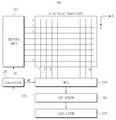
도 1을 참조하면, 터치 감지 장치(100)는 터치 패널(110), 구동 유닛(120), 컨트롤러(130), 멀티플렉서(140), 커패시턴스 센서(150), 계산기(160)를 포함할 수 있다.Referring to FIG. 1, the
터치 패널(110)는 Y축 방향으로 센싱 전극이 행 형태로 배치되어 n개의 Y축 채널을 이루고, X축 방향으로 m개의 센싱 전극이 열 형태로 배치되어 m개의 X축 채널을 이룰 수 있다.The
n개의 행 센싱 전극과 m개의 열 센싱 전극은 서로 접촉되지 않게 서로 다른 레이어 상에 형성될 수 있다.The n row sensing electrodes and the m thermal sensing electrodes may be formed on different layers so that they are not in contact with each other.
X축 채널을 통해서는 자기 커패시턴스 감지신호 및 상호 커패시턴스 감지신호를 출력할 수 있다.The magnetic capacitance sensing signal and the mutual capacitance sensing signal can be output through the X axis channel.
Y축 채널을 통해서는 구동 신호를 입력할 수 있다.A drive signal can be input through the Y-axis channel.
구동 유닛(120)는 컨트롤러(130)로부터의 구동 제어 신호(DC)에 응답하여 n개의 Y축 채널 각각에 상호 커패시턴스의 측정을 위한 구동 신호를 입력할 수 있다.The
컨트롤러(130)는 커패시턴스 센싱 신호(CSS)에 응답하여 상호 커패시턴스를 측정하기 위한 X축 채널을 선택하고, 멀티플렉서의 출력을 제어하기 위한 멀티플렉서 제어신호(MC)를 출력하고, 구동 유닛(120)의 구동 신호의 출력을 제어하기 위한 구동 제어 신호(DC)를 출력할 수 있다.The
멀티플렉서(140)는 멀티플렉서 제어신호(MC)에 응답하여 m개의 X축 채널 중 하나를 선택하여 선택된 X축 채널로부터의 자기 커패시턴스 감지신호 및 상호 커패시턴스 감지신호를 커패시턴스 센서(150)로 출력할 수 있다.The
커패시턴스 센서(150)는 멀티플렉서(150)로부터 출력되는 자기 커패시턴스 감지신호, 상호 커패시턴스 감지신호에 응답하여 특정 채널에 대한 자기 커패시턴스 측정값, 상호 커패시턴스 측정값을 측정할 수 있고, 터치 원시 데이터를 생성하여 계산기(160)로 출력할 수 있다.The
아울러, 커패시턴스 센서(150)는 특정 채널에 대한 자기 커패시턴스 감지신호에 대응하는 자기 커패시턴스 측정값을 포함하는 커패시턴스 센싱신호(CSS)를 컨트롤러(130)로 출력할 수 있다.In addition, the
계산기(160)는 커패시턴스 센서(150)로부터 터치 원시 데이터를 입력받아 터치 좌표를 계산할 수 있다.The
도 2는 도 1의 터치 감지 장치를 이용한 터치 감지 방법을 설명하는 흐름도이다.2 is a flowchart illustrating a touch sensing method using the touch sensing apparatus of FIG.
도 1 및 도 2를 참조하면, 먼저, X축 방향으로 X축 채널에 대한 자기 커패시턴스를 측정한다(S202).Referring to FIGS. 1 and 2, the magnetic capacitance of the X-axis channel is measured in the X-axis direction (S202).
멀티플렉서(140)는 멀티플렉서 제어신호(MC)에 응답하여 각 채널로부터의 자기 커패시턴스 감지신호를 X축 1번 채널부터 m번 채널까지 순서대로 커패시턴스 센서(150)로 출력할 수 있다.The
커패시턴스 센서(150)는 각 채널의 자기 커패시턴스 감지신호에 대응하는 커패시턴스 측정값을 포함한 커패시턴스 센싱신호(CSS)를 생성하여 컨트롤러(130)로 출력하고, 각 채널에 대한 터치 유무를 나타내는 정보(예를 들면, 특정 채널에 대한 커패시턴스 값이 특정 임계치 이상일 경우에 특정 채널에 터치가 발생하였음을 나타낼 수 있음)를 포함하는 터치 원시 데이터를 생성하여 계산기(160)로 출력할 수 있다.The
다음으로, 계산기(160)는 터치 원시 데이터를 바탕으로 하여 X축 터치 좌표를 계산한다(S204).Next, the
다음으로, 측정된 X축 채널의 자기 커패시턴스를 바탕으로 상호 커패시턴스 측정을 위한 X축 채널을 선택한다(S206).Next, an X-axis channel for mutual capacitance measurement is selected based on the measured magnetic capacitance of the X-axis channel (S206).
컨트롤러(130)는 커패시턴스 센싱신호(CSS)에 응답하여 상호 커패시턴스 측정을 위한 X축 채널을 선택할 수 있다.The
도 3은 본 발명의 실시예에 따라 상호 커패시턴스 측정을 위한 채널을 선택하는 것을 설명하는 도면이다.3 is a diagram illustrating selection of a channel for mutual capacitance measurement according to an embodiment of the present invention.
터치 물체가 i번째 X축 채널을 구성하는 센싱 전극 주변에 터치된 경우, i번째 X축 채널에 대한 커패시턴스 측정값(Cs)이 극대값을 형성하고 있고, i-1 번째 채널 및 i+1 번째 채널이 극대값보다 한 단계 작은 커패시턴스 측정값을 형성하고 있고, i-2 번째 채널 및 i+2 번째 채널이 극대값보다 두 단계 작은 커패시턴스 측정값을 형성하고 있다. 이들 채널은 모두 커패시턴스 임계치(Cs,th)보다 크거나 같은 커패시턴스 측정값을 갖는다.When the touch object is touched around the sensing electrode constituting the i-th X-axis channel, the capacitance measurement value Cs for the i-th X-axis channel forms a maximum value, and the i- And the i-2 th channel and the (i + 2) th channel form a capacitance measurement value that is two steps smaller than the maximum value. All of these channels have a capacitance measurement value equal to or greater than the capacitance threshold (Cs, th).
i-3 번째 채널 및 i+3 번째 채널은 커패시턴스 임계치(Csth)보다 작은 커패시턴스 측정값을 갖는다.The (i-3) -th channel and the (i + 3) -th channel have a capacitance measurement value smaller than the capacitance threshold value Csth.
실시예에 따라서는, 컨트롤러(130)는 커패시턴스 측정값(Cs)이 극대값을 갖는 i번째 채널을 상호 커패시턴스 측정을 위한 X축 채널로 선택할 수 있다.According to an embodiment, the
다른 실시예에 따라서는, 컨트롤러(130)는 커패시턴스 측정값(Cs)이 극대값부터 큰 순서대로 소정 개수(예컨대, 3)의 측정값을 갖는 채널인, i-1, i, i+1 번째 채널을 상호 커패시턴스 측정을 위한 X축 채널로 선택할 수 있다.According to another embodiment, the
또 다른 실시예에 따라서는, 컨트롤러(130)는 커패시턴스 임계치(Cs,th)보다 크거나 같은 채널인, i-2, i-1, i, i+1, i+2 번째 채널을 상호 커패시턴스 측정을 위한 X축 채널로 선택할 수 있다.According to another embodiment, the
다음으로, Y축 채널을 송신단으로 하고 선택된 X축 채널을 수신단으로 하여 상호 커패시턴스를 측정한다(S208).Next, the mutual capacitance is measured using the Y-axis channel as the transmitting end and the selected X-axis channel as the receiving end (S208).
도 4 및 도 5는 본 발명의 실시예에 따라 상호 커패시턴스 측정을 설명하기 위한 도면이다.4 and 5 are views for explaining mutual capacitance measurement according to an embodiment of the present invention.
도 4를 참조하면, X축 채널 중 i번째 채널과 j번째 채널에, Y축 채널 중 o 번째 채널과 p번째 채널에 터치가 발생되어, X축 채널 중 i번째 채널과 j번째 채널이 상호 커패시턴스 측정을 위한 X축 채널로 선택된 경우이다.Referring to FIG. 4, a touch is generated in the i-th channel and the j-th channel in the X-axis channel and in the o-th channel and the p-th channel in the Y-axis channel, It is selected as the X axis channel for measurement.
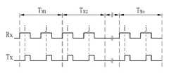
도 5를 참조하면, 1번째 상호 커패시턴스 감지 주기(TM1) 동안에, 수신단인 X축 i번째 채널의 센싱 전극에 수신단 구동신호(Rx)의 펄스를 인가하고, 수신단인 X축 j번째 채널의 센싱 전극에 수신단 구동신호(Rx)의 펄스를 인가하면서, 송신단 구동신호(Tx)의 펄스를 수신단 구동신호의 펄스의 50% 타이밍에 동기되게 Y축 채널 중 1번째 채널의 센싱 전극에 인가하게 된다.Referring to FIG. 5, during the first mutual capacitance sensing period TM1 , a pulse of the receiving end driving signal Rx is applied to the sensing electrode of the i-th receiving channel in the X-axis, The pulse of the transmission terminal driving signal Tx is applied to the sensing electrode of the first channel of the Y axis channel in synchronization with the 50% timing of the pulse of the reception terminal driving signal while the pulse of the reception terminal driving signal Rx is applied to the electrode.
계속하여, 2번째 상호 커패시턴스 감지 주기(TM2) 동안에, 수신단인 X축 i번째 채널의 센싱 전극에 수신단 구동신호(Rx)의 펄스를 인가하고, 수신단인 X축 j번째 채널의 센싱 전극에 수신단 구동신호(Rx)의 펄스를 인가하면서, 송신단 구동신호(Tx)의 펄스를 수신단 구동신호의 펄스의 50% 타이밍에 동기되게 Y축 채널 중 2번째 채널의 센싱 전극에 인가하게 된다.During the second mutual capacitance detection period (TM2 ), a pulse of the receiving end driving signal (Rx) is applied to the sensing electrode of the i-th receiving channel of the X axis and the receiving electrode The pulse of the transmission terminal driving signal Tx is applied to the sensing electrode of the second channel of the Y axis channel synchronously with the 50% timing of the pulse of the reception terminal driving signal while applying the pulse of the driving signal Rx.
이런 과정을 계속하여 마지막으로, n번째 상호 커패시턴스 감지 주기(TMn) 동안에, 수신단인 X축 i번째 채널의 센싱 전극에 수신단 구동신호(Rx)의 펄스를 인가하고, 수신단인 X축 j번째 채널의 센싱 전극에 수신단 구동신호(Rx)의 펄스를 인가하면서, 송신단 구동신호(Tx)의 펄스를 수신단 구동신호의 펄스의 50% 타이밍에 동기되게 Y축 채널 중 n번째 채널의 센싱 전극에 인가하게 된다.During the n-th mutual capacitance detection period (TMn ), a pulse of the receiving end driving signal (Rx) is applied to the sensing electrode of the receiving X-axis i-th channel, The pulse of the transmitting end driving signal Tx is applied to the sensing electrode of the n-th channel of the Y-axis channel in synchronization with the 50% timing of the receiving end driving signal while applying the pulse of the receiving end driving signal Rx to the sensing electrode of the Y- do.
실시예에 따라서는, 송신단 구동신호(Tx)의 펄스를 수신단 구동신호의 펄스의 50% 타이밍에 인가하는 것에 한정되지 않고, 송신단 구동신호의 펄스의 펄스폭 내에서 인가하는 것도 가능하다.In some embodiments, the pulse of the transmission terminal driving signal Tx is not limited to the pulse of the reception terminal driving signal but may be applied within the pulse width of the transmission terminal driving signal.
실시예에 따라서는, 펄스를 포지티브 에지로 인가하는 것에 한정되지 않고, 네거티브 에지의 펄스를 인가하는 것도 가능하다. 또한, 도 5에서는 설명의 편의상 펄스 방식의 커패시턴스 감지 방식을 표시하였지만, 다양한 커패시턴스 감지 방식을 사용할 수 있음은 당연하다. 다시 말해, 방식에 따라서는 펄스 폭이나 에지를 사용하지 않을 수 있음은 당연하다. 이미 사용하고 있는 방식으로, 펄스의 숫자를 누적하는 방식과 아날로그 신호를 이용하여 감지되는 신호의 크기를 측정하는 방식이 있다.Depending on the embodiment, it is also possible to apply a negative edge pulse instead of applying the pulse to the positive edge. In FIG. 5, although a pulse type capacitance sensing method is shown for the sake of explanation, it is natural that various capacitance sensing methods can be used. In other words, it is natural that pulse width or edge may not be used depending on the method. There is a method of accumulating the number of pulses and a method of measuring the size of a signal to be sensed using an analog signal in a method that is already used.
송신단 구동신호(Tx)는 컨트롤러(130)의 구동 제어신호(DC)에 응답하는 구동 유닛(120)에 의해 Y축 각 채널의 센싱 전극에 인가될 수 있다.The transmitting end drive signal Tx may be applied to the sensing electrode of each channel of the Y axis by the
수신단 구동신호(Rx)는 컨트롤러(130)의 구동 제어신호(DC)에 응답하는 구동 유닛(120)에 의해 X축 채널 중 i번째 채널과 j번째 채널의 센싱 전극에 별도의 배선을 통해 인가될 수 있다.The receiving end driving signal Rx is applied to the sensing electrodes of the i-th channel and the j-th channel in the X-axis channel through a separate wiring by the driving
멀티플렉서(140)는 컨트롤러(130)의 멀티플렉서 제어신호(MC)에 응답하여 수신단 구동신호의 펄스가 대응하는 수신단 채널에 인가되는 동안에 대응하는 수신단 채널로부터 수신되는 상호 커패시턴스 감지 신호를 커패시턴스 센서(150)로 출력할 수 있다.The
상호 커패시턴스 감지 신호는 수신단 구동신호의 펄스 및 송신단 구동신호의 펄스에 응답하는 응답 신호일 수 있다.The mutual capacitance detection signal may be a pulse of the receiving end driving signal and a response signal responsive to the pulse of the transmitting end driving signal.
커패시턴스 센서(150)는 1번째 부터 n번째 상호 커패시턴스 감지 주기 동안에 발생된 상호 커패시턴스 감지 신호를 수신하여, Y축의 각 채널과 선택된 X축 채널에 대한 상호 커패시턴스를 측정할 수 있다.The
커패시턴스 센서(150)는 선택된 X축 채널에 대한 Y축의 각 채널의 터치 유무를 나타내는 정보(예를 들면, 특정 채널에 대한 상호 커패시턴스 값이 특정 임계치 이상일 경우에 특정 채널에 터치가 발생하였음을 나타낼 수 있음)를 포함하는 터치 원시 데이터를 생성하여 계산기(160)로 출력할 수 있다.The
다음으로, 계산기(160)는 터치 원시 데이터를 바탕으로 Y축 터치 좌표를 계산한다(S210).Next, the
도 6 및 도 7은 본 발명의 실시예에 따라 상호 커패시턴스 측정을 설명하기 위한 도면이다.6 and 7 are views for explaining mutual capacitance measurement according to an embodiment of the present invention.
도 6을 참조하면, X축 채널 중 i번째 채널과 j번째 채널과 k번째 채널에, Y축 채널 중 o 번째 채널과 p번째 채널과 q번째 채널에 터치가 발생되어, X채널 중 i번째 채널과 j번째 채널과 k번째 채널이 상호 커패시턴스 측정을 위한 X축 채널로 선택된 경우이다.Referring to FIG. 6, touches are generated in the i-th channel, the j-th channel, and the k-th channel among the X-axis channels, the o-th channel and the p-th channel and the q- And the j-th channel and the k-th channel are selected as the X-axis channel for mutual capacitance measurement.
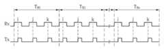
도 7을 참조하면, 1번째 상호 커패시턴스 감지 주기(TM1) 동안에, 수신단인 X축 i번째 채널의 센싱 전극에 수신단 구동신호(Rx)의 펄스를 인가하고 수신단인 X축 j번째 채널의 센싱 전극에 수신단 구동신호(Rx)의 펄스를 인가하고 수신단인 X축 k번째 채널의 센싱 전극에 수신단 구동신호(Rx)의 펄스를 인가하면서, 송신단 구동신호(Tx)의 펄스를 수신단 구동신호의 펄스의 50% 타이밍에 동기되게 Y축 채널 중 1번째 채널의 센싱 전극에 인가하게 된다.Referring to FIG. 7, during the first mutual capacitance sensing period TM1 , a pulse of the receiving end driving signal Rx is applied to the sensing electrode of the receiving X-axis i-th channel, And a pulse of the reception terminal driving signal Rx is applied to the sensing electrode of the Xth, kth, and nth reception channels of the reception terminal, and a pulse of the transmission terminal driving signal Tx is applied to the sensing terminal of the reception terminal driving signal Rx And is applied to the sensing electrode of the first channel of the Y-axis channel synchronously with the 50% timing.
계속하여, 2번째 상호 커패시턴스 감지 주기(TM2) 동안에, 수신단인 X축 i번째 채널의 센싱 전극에 수신단 구동신호(Rx)의 펄스를 인가하고 수신단인 X축 j번째 채널의 센싱 전극에 수신단 구동신호(Rx)의 펄스를 인가하고 수신단인 X축 k번째 채널의 센싱 전극에 수신단 구동신호(Rx)의 펄스를 인가하면서, 송신단 구동신호(Tx)의 펄스를 수신단 구동신호의 펄스의 50% 타이밍에 동기되게 Y축 채널 중 2번째 채널의 센싱 전극에 인가하게 된다.During the second mutual capacitance detection period (TM2 ), a pulse of the reception end driving signal (Rx) is applied to the sensing electrode of the i-th reception channel of the X axis and the receiving electrode A pulse of the signal Rx is applied and a pulse of the reception terminal driving signal Tx is applied to the sensing electrode of the reception terminal X axis, Axis channel to the sensing electrode of the second channel among the Y-axis channels.
이런 과정을 계속하여 마지막으로, n번째 상호 커패시턴스 감지 주기(TMn) 동안에, 수신단인 X축 i번째 채널의 센싱 전극에 수신단 구동신호(Rx)의 펄스를 인가하고, 수신단인 X축 j번째 채널의 센싱 전극에 수신단 구동신호(Rx)의 펄스를 인가하고 수신단인 X축 k번째 채널의 센싱 전극에 수신단 구동신호(Rx)의 펄스를 인가하면서, 송신단 구동신호(Tx)의 펄스를 수신단 구동신호의 펄스의 50% 타이밍에 동기되게 Y축 채널 중 n번째 채널의 센싱 전극에 인가하게 된다.During the n-th mutual capacitance detection period (TMn ), a pulse of the receiving end driving signal (Rx) is applied to the sensing electrode of the receiving X-axis i-th channel, A pulse of the reception terminal driving signal Rx is applied to the sensing electrode of the reception terminal X and a pulse of the reception terminal driving signal Rx is applied to the sensing electrode of the Xth axis kth reception channel, Axis is applied to the sensing electrode of the n-th channel in synchronization with the 50% timing of the pulse of the Y-axis.
실시예에 따라서는, 송신단 구동신호(Tx)의 펄스를 수신단 구동신호의 펄스의 50% 타이밍에 인가하는 것에 한정되지 않고, 송신단 구동신호의 펄스의 펄스폭 내에서 인가하는 것도 가능하다.In some embodiments, the pulse of the transmission terminal driving signal Tx is not limited to the pulse of the reception terminal driving signal but may be applied within the pulse width of the transmission terminal driving signal.
실시예에 따라서는, 펄스를 포지티브 에지로 인가하는 것에 한정되지 않고, 네거티브 에지의 펄스를 인가하는 것도 가능하다.Depending on the embodiment, it is also possible to apply a negative edge pulse instead of applying the pulse to the positive edge.
도 8은 본 발명의 실시예에 따른 터치 감지 장치의 구성도이다.8 is a configuration diagram of a touch sensing apparatus according to an embodiment of the present invention.
도 8을 참조하면, 터치 감지 장치(800)는 터치 패널(810), 스위치(820), 제1 멀티플렉서(830), 구동 유닛(840), 컨트롤러(850), 제2 멀티플렉서(860), 커패시턴스 센서(870), 계산기(880)를 포함할 수 있다.8, the
터치 패널(810)은 Y축 방향으로 센싱 전극이 행 형태로 배치되어 n개의 Y축 채널을 이루고, X축 방향으로 m개의 센싱 전극이 열 형태로 배치되어 m개의 X축 채널을 이룰 수 있다.The
n개의 행 센싱 전극과 m개의 열 센싱 전극은 서로 접촉되지 않게 서로 다른 레이어 상에 형성될 수 있다.The n row sensing electrodes and the m thermal sensing electrodes may be formed on different layers so that they are not in contact with each other.
X축 채널을 통해서는 자기 커패시턴스 감지신호 및 상호 커패시턴스 감지신호를 출력할 수 있다.The magnetic capacitance sensing signal and the mutual capacitance sensing signal can be output through the X axis channel.
Y축 채널을 통해서는 구동 신호를 입력할 수 있고, 자기 커패시턴스 감지신호를 출력할 수 있다.A driving signal can be input through the Y-axis channel, and a magnetic capacitance sensing signal can be output.
스위치(820)는 컨트롤러(850)로부터의 스위치 제어신호(SC)에 응답하여 제1 멀티플렉서(830) 또는 구동 유닛(840)을 선택적으로 Y축 각 채널로 연결할 수 있다.The
제1 멀티플렉서(830)는 제1 멀티플렉서 제어신호(MC1)에 응답하여 n개의 Y축 채널 중 하나를 선택하여 선택된 Y축 채널로부터의 자기 커패시턴스 감지신호를 커패시턴스 센서(870)로 출력할 수 있다.The
구동 유닛(840)는 컨트롤러(850)로부터의 구동 제어신호(DC)에 응답하여 상호 커패시턴스 측정을 위해 선택된 Y축 채널 각각에 상호 커패시턴스의 측정을 위한 구동 신호를 입력할 수 있다.The
컨트롤러(850)는 커패시턴스 센싱 신호(CSS)에 응답하여 상호 커패시턴스를 측정하기 위한 X축 채널 및 Y축 채널을 선택하고, 제1 멀티플렉서 및 제2 멀티플렉서의 출력을 제어하기 위한 제1 멀티플렉서 제어신호 및 제2 멀티플렉서 제어신호(MC1, MC2)를 출력하고, 구동 유닛(840)의 구동 신호의 출력을 제어하기 위한 구동 제어신호(DC)를 출력할 수 있다.The
제2 멀티플렉서(860)는 제2 멀티플렉서 제어신호(MC2)에 응답하여 m개의 X축 채널 중 하나를 선택하여 선택된 X축 채널로부터의 자기 커패시턴스 감지신호 및 상호 커패시턴스 감지신호를 커패시턴스 센서(870)로 출력할 수 있다.The
커패시턴스 센서(870)는 제1 멀티플렉서(830) 및 제2 멀티플렉서(860)로부터 출력되는 자기 커패시턴스 감지신호, 상호 커패시턴스 감지신호에 응답하여 특정 채널에 대한 자기 커패시턴스 측정값, 상호 커패시턴스 측정값을 측정할 수 있고, 터치 원시 데이터를 생성하여 계산기(160)로 출력할 수 있다.The
아울러, 커패시턴스 센서(870)는 특정 채널에 대한 자기 커패시턴스 감지신호에 대응하는 자기 커패시턴스 측정값을 포함하는 커패시턴스 센싱신호(CSS)를 컨트롤러(130)로 출력할 수 있다.In addition, the
계산기(880)는 커패시턴스 센서(870)로부터 터치 원시 데이터를 입력받아 터치 좌표를 계산할 수 있다.The
도 9는 도 8의 터치 감지 장치를 이용한 터치 감지 방법을 설명하는 흐름도이다.9 is a flowchart illustrating a touch sensing method using the touch sensing apparatus of FIG.
도 8 및 도 9를 참조하면, 먼저, X축 방향으로 X축 채널에 대한 자기 커패시턴스를 측정한다(S902).8 and 9, first, the magnetic capacitance of the X-axis channel in the X-axis direction is measured (S902).
제2 멀티플렉서(860)는 제2 멀티플렉서 제어신호(MC2)에 응답하여 X축 각 채널로부터의 자기 커패시턴스 감지신호를 X축 1번 채널부터 m번 채널까지 순서대로 커패시턴스 센서(870)로 출력할 수 있다.The
커패시턴스 센서(870)는 X축 각 채널의 자기 커패시턴스 감지신호에 대응하는 커패시턴스 측정값을 포함한 커패시턴스 센싱신호(CSS)를 생성하여 컨트롤러(850)로 출력하고, X축 각 채널에 대한 터치 유무를 나타내는 정보(예를 들면, 특정 채널에 대한 커패시턴스 값이 특정 임계치 이상일 경우에 특정 채널에 터치가 발생하였음을 나타낼 수 있음)를 포함하는 터치 원시 데이터를 생성하여 계산기(870)로 출력할 수 있다.The
다음으로, 계산기(880)는 터치 원시 데이터를 바탕으로 하여 X축 터치 좌표를 계산한다(S904).Next, the
다음으로, Y축 방향으로 Y축 채널에 대한 자기 커패시턴스를 측정한다(S906).Next, the magnetic capacitance for the Y-axis channel in the Y-axis direction is measured (S906).
스위치(820)는 스위치 제어신호(SC)에 응답하여 n개의 Y축 채널과 제1 멀티플렉서(830)를 연결하여 준다.The
제1 멀티플렉서(830)는 제1 멀티플렉서 제어신호(MC1)에 응답하여 Y축 각 채널로부터의 자기 커패시턴스 감지신호를 Y축 1번 채널부터 n번 채널까지 순서대로 커패시턴스 센서(870)로 출력할 수 있다.The
커패시턴스 센서(870)는 Y축 각 채널의 자기 커패시턴스 감지신호에 대응하는 커패시턴스 측정값을 포함한 커패시턴스 센싱신호(CSS)를 생성하여 컨트롤러(850)로 출력할 수 있다.The
다음으로, 측정된 X축 채널 및 Y축 채널의 자기 커패시턴스를 바탕으로 상호 커패시턴스 측정을 위한 X축 채널 및 Y출 채널을 선택한다(S908).Next, based on the measured magnetic capacitance of the X-axis channel and the Y-axis channel, an X-axis channel and a Y-out channel for mutual capacitance measurement are selected (S908).
컨트롤러(850)는 커패시턴스 센싱신호(CSS)에 응답하여 상호 커패시턴스 측정을 위한 X축 채널 및 Y축 채널을 선택할 수 있다. 상호 커패시턴스 측정을 위한 X축 채널 또는 Y축 채널 선택은 도 3에서 설명한 바와 같으므로 생략하기로 한다.The
다음으로, 선택된 Y축 채널을 송신단으로 하고 선택된 X축 채널을 수신단으로 하여 상호 커패시턴스를 측정한다(S910). 스위치(820)는 스위치 제어신호(SC)에 응답하여 n개의 Y축 채널과 구동 유닛(840)을 연결하여 준다.Next, the mutual capacitance is measured using the selected Y-axis channel as a transmitting end and the selected X-axis channel as a receiving end (S910). The
도 4 및 도 10은 본 발명의 실시예에 따라 상호 커패시턴스 측정을 설명하기 위한 도면이다.4 and 10 are views for explaining mutual capacitance measurement according to an embodiment of the present invention.
도 4를 참조하면, X축 채널 중 i번째 채널과 j번째 채널에, Y축 채널 중 o 번째 채널과 p번째 채널에 터치가 발생되어, X축 채널 중 i번째 채널과 j번째 채널이 상호 커패시턴스 측정을 위한 X축 채널로 선택되고, Y축 채널 중 o번째 채널과 p번째 채널이 상호 커패시턴스 측정을 위한 Y축 채널로 선택된 경우이다.Referring to FIG. 4, a touch is generated in the i-th channel and the j-th channel in the X-axis channel and in the o-th channel and the p-th channel in the Y-axis channel, Axis is selected as the X-axis channel for measurement, and the o-th channel and the p-th channel of the Y-axis channel are selected as the Y-axis channel for mutual capacitance measurement.
도 10을 참조하면, o번 상호 커패시턴스 감지 주기(TMo) 동안에, 수신단인 X축 i번째 채널의 센싱 전극에 수신단 구동신호(Rx)의 펄스를 인가하고, 수신단인 X축 j번째 채널의 센싱 전극에 수신단 구동신호(Rx)의 펄스를 인가하면서, 송신단 구동신호(Tx)의 펄스를 수신단 구동신호의 펄스의 50% 타이밍에 동기되게 Y축 채널 중 o번째 채널의 센싱 전극에 인가하게 된다.Referring to Figure 10, o once mutual capacitance detection period (TMo) while, the receiving end of the X-axis i is the pulse of the receiver drive signal (Rx) on the sensing electrode in the second channel, the sensing of the X-axis j-th channel receiver The pulse of the transmitting terminal driving signal Tx is applied to the sensing electrode of the o-th channel of the Y-axis channel in synchronization with the 50% timing of the receiving terminal driving signal while applying the pulse of the receiving terminal driving signal Rx to the electrode.
계속하여, p번 상호 커패시턴스 감지 주기(TMp) 동안에, 수신단인 X축 i번째 채널의 센싱 전극에 수신단 구동신호(Rx)의 펄스를 인가하고, 수신단인 X축 j번째 채널의 센싱 전극에 수신단 구동신호(Rx)의 펄스를 인가하면서, 송신단 구동신호(Tx)의 펄스를 수신단 구동신호의 펄스의 50% 타이밍에 동기되게 Y축 채널 중 p번째 채널의 센싱 전극에 인가하게 된다.During the p-times mutual capacitance detection period (TMp ), a pulse of the receiving end driving signal (Rx) is applied to the sensing electrode of the receiving X-axis i-th channel and the receiving electrode The pulse of the transmission terminal driving signal Tx is applied to the sensing electrode of the p-th channel of the Y-axis channel in synchronization with the 50% timing of the pulse of the reception terminal driving signal while applying the pulse of the driving signal Rx.
실시예에 따라서는, 송신단 구동신호(Tx)의 펄스를 수신단 구동신호의 펄스의 50% 타이밍에 인가하는 것에 한정되지 않고, 송신단 구동신호의 펄스의 펄스폭 내에서 인가하는 것도 가능하다.In some embodiments, the pulse of the transmission terminal driving signal Tx is not limited to the pulse of the reception terminal driving signal but may be applied within the pulse width of the transmission terminal driving signal.
실시예에 따라서는, 펄스를 포지티브 에지로 인가하는 것에 한정되지 않고, 네거티브 에지의 펄스를 인가하는 것도 가능하다.Depending on the embodiment, it is also possible to apply a negative edge pulse instead of applying the pulse to the positive edge.
송신단 구동신호(Tx)는 컨트롤러(850)의 구동 제어신호(DC)에 응답하는 구동 유닛(840)에 의해 Y축 채널 중 선택된 o번째 채널과 p번째 채널의 센싱 전극에 인가될 수 있다.The transmission terminal driving signal Tx may be applied to the sensing electrodes of the o-th channel and the p-th channel selected from the Y-axis channels by the driving
수신단 구동신호(Rx)는 컨트롤러(850)의 구동 제어 신호(DC)에 응답하는 구동 유닛(840)에 의해 X축 채널 중 i번째 채널과 j번째 채널의 센싱 전극에 별도의 배선을 통해 인가될 수 있다.The receiving end driving signal Rx is applied to the sensing electrodes of the i-th channel and the j-th channel of the X-axis channel through separate wirings by the driving
제2 멀티플렉서(860)는 컨트롤러(850)의 제2 멀티플렉서 제어신호(MC2)에 응답하여 수신단 구동신호의 펄스가 대응하는 수신단 채널에 인가되는 동안에 대응하는 수신단 채널로부터 수신되는 상호 커패시턴스 감지 신호를 커패시턴스 센서(870)로 출력할 수 있다.In response to the second multiplexer control signal MC2 of the
상호 커패시턴스 감지 신호는 수신단 구동신호의 펄스 및 송신단 구동신호의 펄스에 응답하는 응답 신호일 수 있다.The mutual capacitance detection signal may be a pulse of the receiving end driving signal and a response signal responsive to the pulse of the transmitting end driving signal.
커패시턴스 센서(870)는 o번 및 p번 상호 커패시턴스 감지 주기 동안에 발생된 상호 커패시턴스 감지 신호를 수신하여, 선택된 Y축 채널과 선택된 X축 채널에 대한 상호 커패시턴스를 측정할 수 있다.The
커패시턴스 센서(870)는 선택된 X축 채널에 대한 선택된 Y축 채널의 터치 유무를 나타내는 정보(예를 들면, 특정 채널에 대한 상호 커패시턴스 값이 특정 임계치 이상일 경우에 특정 채널에 터치가 발생하였음을 나타낼 수 있음)를 포함하는 터치 원시 데이터를 생성하여 계산기(880)로 출력할 수 있다.The
다음으로, 계산기(880)는 터치 원시 데이터를 바탕으로 Y축 터치 좌표를 계산한다(S912).Next, the
도 6 및 도 11은 본 발명의 실시예에 따라 상호 커패시턴스 측정을 설명하기 위한 도면이다.6 and 11 are views for explaining mutual capacitance measurement according to an embodiment of the present invention.
도 6을 참조하면, X축 채널 중 i번째 채널과 j번째 채널과 k번째 채널에, Y축 채널 중 o 번째 채널과 p번째 채널과 q번째 채널에 터치가 발생되어, X채널 중 i번째 채널과 j번째 채널과 k번째 채널이 상호 커패시턴스 측정을 위한 X축 채널로 선택되고 Y채널 중 o 번째 채널과 p번째 채널과 q번째 채널이 상호 커패시턴스 측정을 위한 Y축 채널로 선택된 경우이다.Referring to FIG. 6, touches are generated in the i-th channel, the j-th channel, and the k-th channel among the X-axis channels, the o-th channel and the p-th channel and the q- And the j-th channel and the k-th channel are selected as the X-axis channel for mutual capacitance measurement, and the o-th channel and the p-th channel and the q-th channel of the Y-channel are selected as the Y-axis channel for mutual capacitance measurement.
도 11을 참조하면, o번 상호 커패시턴스 감지 주기(TMo) 동안에, 수신단인 X축 i번째 채널의 센싱 전극에 수신단 구동신호(Rx)의 펄스를 인가하고 수신단인 X축 j번째 채널의 센싱 전극에 수신단 구동신호(Rx)의 펄스를 인가하고 수신단인 X축 k번째 채널의 센싱 전극에 수신단 구동신호(Rx)의 펄스를 인가하면서, 송신단 구동신호(Tx)의 펄스를 수신단 구동신호의 펄스의 50% 타이밍에 동기되게 Y축 채널 중 o번째 채널의 센싱 전극에 인가하게 된다.11, a pulse of the receiving end driving signal Rx is applied to the sensing electrode of the receiving X-axis i-th channel during the o-th mutual capacitance sensing period TMo , And a pulse of the reception terminal driving signal Rx is applied to the sensing electrode of the Xth, kth, and nth reception channels of the reception terminal, and a pulse of the transmission terminal driving signal Tx is applied to the sensing terminal of the reception terminal driving signal Rx And is applied to the sensing electrode of the o-th channel of the Y-axis channel synchronously with the 50% timing.
계속하여, p번 상호 커패시턴스 감지 주기(TMp) 동안에, 수신단인 X축 i번째 채널의 센싱 전극에 수신단 구동신호(Rx)의 펄스를 인가하고 수신단인 X축 j번째 채널의 센싱 전극에 수신단 구동신호(Rx)의 펄스를 인가하고 수신단인 X축 k번째 채널의 센싱 전극에 수신단 구동신호(Rx)의 펄스를 인가하면서, 송신단 구동신호(Tx)의 펄스를 수신단 구동신호의 펄스의 50% 타이밍에 동기되게 Y축 채널 중 p번째 채널의 센싱 전극에 인가하게 된다.During the p-times mutual capacitance detection period (TMp ), a pulse of the receiving end driving signal (Rx) is applied to the sensing electrode of the receiving X-axis i-th channel and the receiving- A pulse of the signal Rx is applied and a pulse of the reception terminal driving signal Tx is applied to the sensing electrode of the reception terminal X axis, Axis channel to the sensing electrode of the p-th channel among the Y-axis channels.
계속하여, q번 상호 커패시턴스 감지 주기(TMq) 동안에, 수신단인 X축 i번째 채널의 센싱 전극에 수신단 구동신호(Rx)의 펄스를 인가하고, 수신단인 X축 j번째 채널의 센싱 전극에 수신단 구동신호(Rx)의 펄스를 인가하고 수신단인 X축 k번째 채널의 센싱 전극에 수신단 구동신호(Rx)의 펄스를 인가하면서, 송신단 구동신호(Tx)의 펄스를 수신단 구동신호의 펄스의 50% 타이밍에 동기되게 Y축 채널 중 q번째 채널의 센싱 전극에 인가하게 된다.Next , during the q-th mutual capacitance detection period (TMq ), a pulse of the receiving end driving signal (Rx) is applied to the sensing electrode of the i-th receiving channel of the X axis and the receiving electrode A pulse of the driving signal Rx is applied and a pulse of the transmitting terminal driving signal Tx is applied to the sensing electrode of the receiving terminal X axis, Axis is applied to the sensing electrode of the q-th channel in the Y-axis channel in synchronization with the timing.
실시예에 따라서는, 송신단 구동신호(Tx)의 펄스를 수신단 구동신호의 펄스의 50% 타이밍에 인가하는 것에 한정되지 않고, 송신단 구동신호의 펄스의 펄스폭 내에서 인가하는 것도 가능하다.In some embodiments, the pulse of the transmission terminal driving signal Tx is not limited to the pulse of the reception terminal driving signal but may be applied within the pulse width of the transmission terminal driving signal.
실시예에 따라서는, 펄스를 포지티브 에지로 인가하는 것에 한정되지 않고, 네거티브 에지의 펄스를 인가하는 것도 가능하다.Depending on the embodiment, it is also possible to apply a negative edge pulse instead of applying the pulse to the positive edge.
지금까지는 설명의 편의상 모든 Y축 채널에 대하여 자기 커패시턴스를 측정하는 것으로 하였으나, 일부만 측정하거나, 전체의 터치 영역을 구분 영역으로 나눈 후 도 2와 도 9의 방법을 조합하여 사용할 수 있음은 당연하다.For the convenience of explanation, the magnetic capacitance is measured for all the Y-axis channels. However, it is natural that only a part of the measurement is performed, or the entire touch area is divided into the division areas and then the combination of the methods of FIGS. 2 and 9 can be used.
상기에서는 본 발명의 바람직한 실시예를 참조하여 설명하였지만, 해당 기술분야의 숙련된 당업자는 하기의 특허 청구 범위에 기재된 본 발명의 사상 및 영역으로부터 벗어나지 않는 범위 내에서 본 발명을 다양하게 수정 및 변형시킬 수 있음을 이해할 수 있을 것이다.It will be apparent to those skilled in the art that various modifications and variations can be made in the present invention without departing from the spirit or scope of the invention as defined in the appended claims. It can be understood that it is possible.
본 발명은 터치 감지 장치에 유용하게 이용될 수 있다.The present invention can be advantageously used in a touch sensing apparatus.
100, 800 : 터치 감지 장치
110, 810 : 터치 패널
120, 840 : 구동 유닛
140 : 멀티플렉서
830: 제1 멀티플렉서
860 : 제2 멀티플렉서
130, 850 : 컨트롤러
150, 870 : 커패시턴스 센서
160, 880 : 계산기100, 800: Touch sensing device
110, 810: Touch panel
120, 840: drive unit
140: Multiplexer
830: first multiplexer
860: second multiplexer
130, 850:
150, 870: Capacitance sensor
160, 880: Calculator
Claims (20)
Translated fromKorean상기 다수의 제1 채널에 대한 자기 커패시턴스를 측정하고, 측정된 자기 커패시턴스를 이용하여 다수의 제1 채널 중에서 상호 커패시턴스 측정을 위한 채널을 선택하고, 상기 다수의 제2 채널과 선택된 채널 간의 상호 커패시턴스를 측정하는 제어 수단을 포함하고,
상기 제어 수단은,
상기 다수의 제1 채널에 대하여 측정된 자기 커패시턴스 중에서 극대값을 갖는 채널을 상호 커패시턴스 측정을 위한 채널로 선택하고,
상기 제어 수단은,
상기 다수의 제2 채널 중 특정의 채널과 상기 다수의 제1 채널 중 선택된 채널 간의 상호 커패시턴스를 측정하는 과정인 상호 커패시턴스 측정 과정을 상기 다수의 제2 채널에 대하여 순차적으로 진행하고,
상기 상호 커패시턴스 측정 과정은,
상기 다수의 제2 채널 중 특정의 채널을 송신단으로 하고, 상기 다수의 제1 채널 중 선택된 채널을 수신단으로 하여 진행하고,
상기 상호 커패시턴스 측정 과정은,
상기 다수의 제1 채널 중 선택된 채널에 순차로 제1 펄스폭을 갖는 제1 펄스를 인가하고,
상기 다수의 제2 채널 중 특정의 채널에 상기 제1 펄스폭 내에 포함되는 제2 펄스폭을 갖는 제2 펄스를 인가하는 것을 포함하는 터치 감지 장치.A touch comprising a plurality of first sensing electrodes constituting a corresponding plurality of first channels and arranged in a first direction and a plurality of second sensing electrodes constituting a corresponding plurality of second channels and arranged in a second direction, panel; And
Measuring a magnetic capacitance for the plurality of first channels, selecting a channel for mutual capacitance measurement among the plurality of first channels using the measured magnetic capacitance, and measuring a mutual capacitance between the plurality of second channels and the selected channel And control means for measuring,
Wherein,
A channel having a maximum value among the magnetic capacitances measured for the plurality of first channels is selected as a channel for mutual capacitance measurement,
Wherein,
A mutual capacitance measurement process of measuring a mutual capacitance between a specific one of the plurality of second channels and a selected one of the plurality of first channels is sequentially performed for the plurality of second channels,
The mutual capacitance measurement process includes:
A specific channel among the plurality of second channels is used as a transmitting terminal, a selected one of the plurality of first channels is used as a receiving terminal,
The mutual capacitance measurement process includes:
Applying a first pulse having a first pulse width sequentially to selected ones of the plurality of first channels,
And applying a second pulse having a second pulse width included in the first pulse width to a specific one of the plurality of second channels.
상기 다수의 제1 채널에 대한 자기 커패시턴스를 측정하고, 측정된 자기 커패시턴스를 이용하여 다수의 제1 채널 중에서 상호 커패시턴스 측정을 위한 채널을 선택하고, 상기 다수의 제2 채널과 선택된 채널 간의 상호 커패시턴스를 측정하는 제어 수단을 포함하고,
상기 제어 수단은,
상기 다수의 제1 채널에 대하여 측정된 자기 커패시턴스 중에서 극대값을 갖는 채널을 포함하는 주변 채널 중에서 자기 커패시턴스가 큰 순서대로인 소정 개수의 채널을 상호 커패시턴스 측정을 위한 채널로 선택하고,
상기 제어 수단은,
상기 다수의 제2 채널 중 특정의 채널과 상기 다수의 제1 채널 중 선택된 채널 간의 상호 커패시턴스를 측정하는 과정인 상호 커패시턴스 측정 과정을 상기 다수의 제2 채널에 대하여 순차적으로 진행하고,
상기 상호 커패시턴스 측정 과정은,
상기 다수의 제2 채널 중 특정의 채널을 송신단으로 하고, 상기 다수의 제1 채널 중 선택된 채널을 수신단으로 하여 진행하고,
상기 상호 커패시턴스 측정 과정은,
상기 다수의 제1 채널 중 선택된 채널에 순차로 제1 펄스폭을 갖는 제1 펄스를 인가하고,
상기 다수의 제2 채널 중 특정의 채널에 상기 제1 펄스폭 내에 포함되는 제2 펄스폭을 갖는 제2 펄스를 인가하는 것을 포함하는 터치 감지 장치.A touch comprising a plurality of first sensing electrodes constituting a corresponding plurality of first channels and arranged in a first direction and a plurality of second sensing electrodes constituting a corresponding plurality of second channels and arranged in a second direction, panel; And
Measuring a magnetic capacitance for the plurality of first channels, selecting a channel for mutual capacitance measurement among the plurality of first channels using the measured magnetic capacitance, and measuring a mutual capacitance between the plurality of second channels and the selected channel And control means for measuring,
Wherein,
Selecting a predetermined number of channels as mutual capacitance measurement channels from among the peripheral channels including the channel having the maximum value among the magnetic capacitances measured for the plurality of first channels in the order of large magnetic capacitance,
Wherein,
A mutual capacitance measurement process of measuring a mutual capacitance between a specific one of the plurality of second channels and a selected one of the plurality of first channels is sequentially performed for the plurality of second channels,
The mutual capacitance measurement process includes:
A specific channel among the plurality of second channels is used as a transmitting terminal, a selected one of the plurality of first channels is used as a receiving terminal,
The mutual capacitance measurement process includes:
Applying a first pulse having a first pulse width sequentially to selected ones of the plurality of first channels,
And applying a second pulse having a second pulse width included in the first pulse width to a specific one of the plurality of second channels.
상기 다수의 제1 채널에 대한 자기 커패시턴스를 측정하고, 측정된 자기 커패시턴스를 이용하여 다수의 제1 채널 중에서 상호 커패시턴스 측정을 위한 채널을 선택하고, 상기 다수의 제2 채널과 선택된 채널 간의 상호 커패시턴스를 측정하는 제어 수단을 포함하고,
상기 제어 수단은,
상기 다수의 제1 채널에 대하여 측정된 자기 커패시턴스 중에서 극대값을 갖는 채널을 포함하는 주변 채널 중에서 자기 커패시턴스가 소정 임계치보다 크거나 같은 채널을 상호 커패시턴스 측정을 위한 채널로 선택하고,
상기 제어 수단은,
상기 다수의 제2 채널 중 특정의 채널과 상기 다수의 제1 채널 중 선택된 채널 간의 상호 커패시턴스를 측정하는 과정인 상호 커패시턴스 측정 과정을 상기 다수의 제2 채널에 대하여 순차적으로 진행하고,
상기 상호 커패시턴스 측정 과정은,
상기 다수의 제2 채널 중 특정의 채널을 송신단으로 하고, 상기 다수의 제1 채널 중 선택된 채널을 수신단으로 하여 진행하고,
상기 상호 커패시턴스 측정 과정은,
상기 다수의 제1 채널 중 선택된 채널에 순차로 제1 펄스폭을 갖는 제1 펄스를 인가하고,
상기 다수의 제2 채널 중 특정의 채널에 상기 제1 펄스폭 내에 포함되는 제2 펄스폭을 갖는 제2 펄스를 인가하는 것을 포함하는 터치 감지 장치.A touch comprising a plurality of first sensing electrodes constituting a corresponding plurality of first channels and arranged in a first direction and a plurality of second sensing electrodes constituting a corresponding plurality of second channels and arranged in a second direction, panel; And
Measuring a magnetic capacitance for the plurality of first channels, selecting a channel for mutual capacitance measurement among the plurality of first channels using the measured magnetic capacitance, and measuring a mutual capacitance between the plurality of second channels and the selected channel And control means for measuring,
Wherein,
Selecting a channel having a magnetic capacitance greater than or equal to a predetermined threshold as a channel for mutual capacitance measurement among peripheral channels including a channel having a maximum value among the magnetic capacitances measured for the plurality of first channels,
Wherein,
A mutual capacitance measurement process of measuring a mutual capacitance between a specific one of the plurality of second channels and a selected one of the plurality of first channels is sequentially performed for the plurality of second channels,
The mutual capacitance measurement process includes:
A specific channel among the plurality of second channels is used as a transmitting terminal, a selected one of the plurality of first channels is used as a receiving terminal,
The mutual capacitance measurement process includes:
Applying a first pulse having a first pulse width sequentially to selected ones of the plurality of first channels,
And applying a second pulse having a second pulse width included in the first pulse width to a specific one of the plurality of second channels.
상기 다수의 제1 채널에 대한 제1 자기 커패시턴스를 측정하고, 상기 다수의 제2 채널에 대한 제2 자기 커패시턴스를 측정하고, 측정된 제1 자기 커패시턴스를 이용하여 다수의 제1 채널 중에서 상호 커패시턴스 측정을 위한 제3 채널을 선택하고, 측정된 제2 자기 커패시턴스를 이용하여 다수의 제2 채널 중에서 상호 커패시턴스 측정을 위한 제4 채널을 선택하고, 상기 제4 채널과 상기 제3 채널 간의 상호 커패시턴스를 측정하는 제어 수단을 포함하고,
상기 제어 수단은,
상기 제1 자기 커패시턴스 중에서 극대값을 갖는 채널을 상기 제3 채널로 선택하고,
상기 제2 자기 커패시턴스 중에서 극대값을 갖는 채널을 상기 제4 채널로 선택하고,
상기 제어 수단은,
상기 제4 채널 중 특정의 채널과 상기 제3 채널 간의 상호 커패시턴스를 측정하는 과정인 상호 커패시턴스 측정 과정을 상기 제4 채널에 대하여 순차적으로 진행하고,
상기 상호 커패시턴스 측정 과정은,
상기 제4 채널 중 특정의 채널을 송신단으로 하고, 상기 제3 채널을 수신단으로 하여 진행하고,
상기 상호 커패시턴스 측정 과정은,
상기 제3 채널에 순차로 제1 펄스폭을 갖는 제1 펄스를 인가하고,
상기 제4 채널 중 특정의 채널에 상기 제1 펄스폭 내에 포함되는 제2 펄스폭을 갖는 제2 펄스를 인가하는 것을 포함하는 터치 감지 장치.A touch comprising a plurality of first sensing electrodes constituting a corresponding plurality of first channels and arranged in a first direction and a plurality of second sensing electrodes constituting a corresponding plurality of second channels and arranged in a second direction, panel; And
Measuring a first magnetic capacitance for the plurality of first channels, measuring a second magnetic capacitance for the plurality of second channels, measuring mutual capacitance among the plurality of first channels using the measured first magnetic capacitance Selects a fourth channel for mutual capacitance measurement among the plurality of second channels using the measured second magnetic capacitance, measures a mutual capacitance between the fourth channel and the third channel And control means
Wherein,
Selecting a channel having a maximum value among the first magnetic capacities as the third channel,
A channel having a maximum value among the second magnetic capacitances is selected as the fourth channel,
Wherein,
A mutual capacitance measurement process of measuring a mutual capacitance between a specific channel of the fourth channel and the third channel is sequentially performed for the fourth channel,
The mutual capacitance measurement process includes:
A specific channel among the fourth channels as a transmitting terminal, a third channel as a receiving terminal,
The mutual capacitance measurement process includes:
Applying a first pulse having a first pulse width sequentially to the third channel,
And applying a second pulse having a second pulse width included in the first pulse width to a specific one of the fourth channels.
상기 다수의 제1 채널에 대한 제1 자기 커패시턴스를 측정하고, 상기 다수의 제2 채널에 대한 제2 자기 커패시턴스를 측정하고, 측정된 제1 자기 커패시턴스를 이용하여 다수의 제1 채널 중에서 상호 커패시턴스 측정을 위한 제3 채널을 선택하고, 측정된 제2 자기 커패시턴스를 이용하여 다수의 제2 채널 중에서 상호 커패시턴스 측정을 위한 제4 채널을 선택하고, 상기 제4 채널과 상기 제3 채널 간의 상호 커패시턴스를 측정하는 제어 수단을 포함하고,
상기 제어 수단은,
상기 제1 자기 커패시턴스 중에서 극대값을 갖는 채널을 포함하는 주변 채널 중에서 자기 커패시턴스가 큰 순서대로인 소정 개수의 채널을 상기 제3 채널로 선택하고,
상기 제2 자기 커패시턴스 중에서 극대값을 갖는 채널을 포함하는 주변 채널 중에서 자기 커패시턴스가 큰 순서대로인 소정 개수의 채널을 상기 제4 채널로 선택하고,
상기 제어 수단은,
상기 제4 채널 중 특정의 채널과 상기 제3 채널 간의 상호 커패시턴스를 측정하는 과정인 상호 커패시턴스 측정 과정을 상기 제4 채널에 대하여 순차적으로 진행하고,
상기 상호 커패시턴스 측정 과정은,
상기 제4 채널 중 특정의 채널을 송신단으로 하고, 상기 제3 채널을 수신단으로 하여 진행하고,
상기 상호 커패시턴스 측정 과정은,
상기 제3 채널에 순차로 제1 펄스폭을 갖는 제1 펄스를 인가하고,
상기 제4 채널 중 특정의 채널에 상기 제1 펄스폭 내에 포함되는 제2 펄스폭을 갖는 제2 펄스를 인가하는 것을 포함하는 터치 감지 장치.A touch comprising a plurality of first sensing electrodes constituting a corresponding plurality of first channels and arranged in a first direction and a plurality of second sensing electrodes constituting a corresponding plurality of second channels and arranged in a second direction, panel; And
Measuring a first magnetic capacitance for the plurality of first channels, measuring a second magnetic capacitance for the plurality of second channels, measuring mutual capacitance among the plurality of first channels using the measured first magnetic capacitance Selects a fourth channel for mutual capacitance measurement among the plurality of second channels using the measured second magnetic capacitance, measures a mutual capacitance between the fourth channel and the third channel And control means
Wherein,
Selecting a predetermined number of channels among the peripheral channels including the channel having the maximum value among the first magnetic capacities in the order of increasing magnetic capacitance as the third channel,
Selecting a predetermined number of channels among the peripheral channels including the channel having the maximum value among the second magnetic capacitances in the order of increasing magnetic capacitance as the fourth channel,
Wherein,
A mutual capacitance measurement process of measuring a mutual capacitance between a specific channel of the fourth channel and the third channel is sequentially performed for the fourth channel,
The mutual capacitance measurement process includes:
A specific channel among the fourth channels as a transmitting terminal, a third channel as a receiving terminal,
The mutual capacitance measurement process includes:
Applying a first pulse having a first pulse width sequentially to the third channel,
And applying a second pulse having a second pulse width included in the first pulse width to a specific one of the fourth channels.
상기 다수의 제1 채널에 대한 제1 자기 커패시턴스를 측정하고, 상기 다수의 제2 채널에 대한 제2 자기 커패시턴스를 측정하고, 측정된 제1 자기 커패시턴스를 이용하여 다수의 제1 채널 중에서 상호 커패시턴스 측정을 위한 제3 채널을 선택하고, 측정된 제2 자기 커패시턴스를 이용하여 다수의 제2 채널 중에서 상호 커패시턴스 측정을 위한 제4 채널을 선택하고, 상기 제4 채널과 상기 제3 채널 간의 상호 커패시턴스를 측정하는 제어 수단을 포함하고,
상기 제어 수단은,
상기 제1 자기 커패시턴스 중에서 극대값을 갖는 채널을 포함하는 주변 채널 중에서 자기 커패시턴스가 소정 임계치보다 크거나같은 채널을 상기 제3 채널로 선택하고,
상기 제2 자기 커패시턴스 중에서 극대값을 갖는 채널을 포함하는 주변 채널 중에서 자기 커패시턴스가 소정 임계치보다 크거나 같은 채널을 상기 제4 채널로 선택하고,
상기 제어 수단은,
상기 제4 채널 중 특정의 채널과 상기 제3 채널 간의 상호 커패시턴스를 측정하는 과정인 상호 커패시턴스 측정 과정을 상기 제4 채널에 대하여 순차적으로 진행하고,
상기 상호 커패시턴스 측정 과정은,
상기 제4 채널 중 특정의 채널을 송신단으로 하고, 상기 제3 채널을 수신단으로 하여 진행하고,
상기 상호 커패시턴스 측정 과정은,
상기 제3 채널에 순차로 제1 펄스폭을 갖는 제1 펄스를 인가하고,
상기 제4 채널 중 특정의 채널에 상기 제1 펄스폭 내에 포함되는 제2 펄스폭을 갖는 제2 펄스를 인가하는 것을 포함하는 터치 감지 장치.A touch comprising a plurality of first sensing electrodes constituting a corresponding plurality of first channels and arranged in a first direction and a plurality of second sensing electrodes constituting a corresponding plurality of second channels and arranged in a second direction, panel; And
Measuring a first magnetic capacitance for the plurality of first channels, measuring a second magnetic capacitance for the plurality of second channels, measuring mutual capacitance among the plurality of first channels using the measured first magnetic capacitance Selects a fourth channel for mutual capacitance measurement among the plurality of second channels using the measured second magnetic capacitance, measures a mutual capacitance between the fourth channel and the third channel And control means
Wherein,
Selecting a channel having a magnetic capacitance greater than or equal to a predetermined threshold among the peripheral channels including the channel having the maximum value among the first magnetic capacities as the third channel,
Selecting a channel having a magnetic capacitance greater than or equal to a predetermined threshold among the peripheral channels including the channel having the maximum value among the second magnetic capacities as the fourth channel,
Wherein,
A mutual capacitance measurement process of measuring a mutual capacitance between a specific channel of the fourth channel and the third channel is sequentially performed for the fourth channel,
The mutual capacitance measurement process includes:
A specific channel among the fourth channels as a transmitting terminal, a third channel as a receiving terminal,
The mutual capacitance measurement process includes:
Applying a first pulse having a first pulse width sequentially to the third channel,
And applying a second pulse having a second pulse width included in the first pulse width to a specific one of the fourth channels.
다수의 제1 채널에 대하여 자기 커패시턴스를 측정하고,
측정된 자기 커패시턴스를 이용하여, 다수의 제1 채널 중에서 상호 커패시턴스 측정을 위한 채널을 선택하고,
상기 다수의 제2 채널과 선택된 채널 간의 상호 커패시턴스를 측정하는 것을 포함하고,
상기 상호 커패시턴스 측정을 위한 채널을 선택하는 것은,
상기 다수의 제1 채널에 대하여 측정된 자기 커패시턴스 중에서 극대값을 갖는 채널을 상호 커패시턴스 측정을 위한 채널로 선택하는 것을 포함하고,
상기 상호 커패시턴스를 측정하는 것은,
상기 다수의 제2 채널 중 특정의 채널과 상기 다수의 제1 채널 중 선택된 채널 간의 상호 커패시턴스를 측정하는 과정인 상호 커패시턴스 측정 과정을 상기 다수의 제2 채널에 대하여 순차적으로 진행하는 것을 포함하고,
상기 상호 커패시턴스 측정 과정은,
상기 다수의 제1 채널 중 선택된 채널에 순차로 제1 펄스폭을 갖는 제1 펄스를 인가하고,
상기 다수의 제2 채널 중 특정의 채널에 상기 제1 펄스폭 내에 포함되는 제2 펄스폭을 갖는 제2 펄스를 인가하는 것을 포함하는 터치 감지 방법.A touch comprising a plurality of first sensing electrodes constituting a corresponding plurality of first channels and arranged in a first direction and a plurality of second sensing electrodes constituting a corresponding plurality of second channels and arranged in a second direction, A touch sensing method of a touch sensing device including a panel,
Measuring a magnetic capacitance with respect to a plurality of first channels,
Selecting a channel for mutual capacitance measurement among a plurality of first channels using the measured magnetic capacitance,
Measuring a mutual capacitance between the plurality of second channels and a selected channel,
Selecting a channel for the mutual capacitance measurement comprises:
Selecting a channel having a maximum value among the magnetic capacitances measured for the plurality of first channels as a channel for mutual capacitance measurement,
Measuring the mutual capacitance may comprise:
And measuring a mutual capacitance between a specific one of the plurality of second channels and a selected one of the plurality of first channels, the method comprising: sequentially measuring a mutual capacitance measurement process for the plurality of second channels;
The mutual capacitance measurement process includes:
Applying a first pulse having a first pulse width sequentially to selected ones of the plurality of first channels,
And applying a second pulse having a second pulse width included in the first pulse width to a specific one of the plurality of second channels.
다수의 제1 채널 및 다수의 제2 채널에 대하여 자기 커패시턴스를 측정하고,
측정된 자기 커패시턴스를 이용하여, 다수의 제1 채널 중에서 상호 커패시턴스 측정을 위한 제3 채널 및 다수의 제2 채널 중에서 상호 커패시턴스 측정을 위한 제4 채널을 선택하고,
상기 제4 채널과 상기 제3 채널 간의 상호 커패시턴스를 측정하는 것을 포함하고,
상기 제3 채널 및 상기 제4 채널을 선택하는 것은,
상기 다수의 제1 채널에 대하여 측정된 자기 커패시턴스 중에서 극대값을 갖는 채널을 상기 제3 채널로 선택하고,
상기 다수의 제2 채널에 대하여 측정된 자기 커패시턴스 중에서 극대값을 갖는 채널을 상기 제4 채널로 선택하는 것을 포함하고,
상기 상호 커패시턴스를 측정하는 것은,
상기 제4 채널 중 특정의 채널과 상기 제3 채널 간의 상호 커패시턴스를 측정하는 과정인 상호 커패시턴스 측정 과정을 상기 제4 채널에 대하여 순차적으로 진행하는 것을 포함하고,
상기 상호 커패시턴스 측정 과정은,
상기 제3 채널에 순차로 제1 펄스폭을 갖는 제1 펄스를 인가하고,
상기 제4 채널 중 특정의 채널에 상기 제1 펄스폭 내에 포함되는 제2 펄스폭을 갖는 제2 펄스를 인가하는 것을 포함하는 터치 감지 방법.A touch comprising a plurality of first sensing electrodes constituting a corresponding plurality of first channels and arranged in a first direction and a plurality of second sensing electrodes constituting a corresponding plurality of second channels and arranged in a second direction, A touch sensing method of a touch sensing device including a panel,
Measuring magnetic capacitance for a plurality of first channels and a plurality of second channels,
A third channel for mutual capacitance measurement and a fourth channel for mutual capacitance measurement among a plurality of second channels are selected from a plurality of first channels using the measured magnetic capacitance,
Measuring a mutual capacitance between the fourth channel and the third channel,
The third channel and the fourth channel are selected,
Selecting a channel having a maximum value among the magnetic capacitances measured for the plurality of first channels as the third channel,
And selecting a channel having a maximum value among the magnetic capacitances measured for the plurality of second channels as the fourth channel,
Measuring the mutual capacitance may comprise:
And measuring a mutual capacitance between the specific channel and the third channel of the fourth channel, wherein the mutual capacitance measurement process is sequentially performed for the fourth channel,
The mutual capacitance measurement process includes:
Applying a first pulse having a first pulse width sequentially to the third channel,
And applying a second pulse having a second pulse width included in the first pulse width to a specific one of the fourth channels.
Priority Applications (1)
| Application Number | Priority Date | Filing Date | Title |
|---|---|---|---|
| KR1020130114030AKR101486493B1 (en) | 2013-09-25 | 2013-09-25 | Touch sensing apparatus using hybrid capacitance sensing operation and method thereof |
Applications Claiming Priority (1)
| Application Number | Priority Date | Filing Date | Title |
|---|---|---|---|
| KR1020130114030AKR101486493B1 (en) | 2013-09-25 | 2013-09-25 | Touch sensing apparatus using hybrid capacitance sensing operation and method thereof |
Publications (1)
| Publication Number | Publication Date |
|---|---|
| KR101486493B1true KR101486493B1 (en) | 2015-01-27 |
Family
ID=52592628
Family Applications (1)
| Application Number | Title | Priority Date | Filing Date |
|---|---|---|---|
| KR1020130114030AExpired - Fee RelatedKR101486493B1 (en) | 2013-09-25 | 2013-09-25 | Touch sensing apparatus using hybrid capacitance sensing operation and method thereof |
Country Status (1)
| Country | Link |
|---|---|
| KR (1) | KR101486493B1 (en) |
Cited By (3)
| Publication number | Priority date | Publication date | Assignee | Title |
|---|---|---|---|---|
| KR101800798B1 (en)* | 2016-02-19 | 2017-11-29 | 엘지디스플레이 주식회사 | Driving circuit, touch display device, and method for driving the touch display device |
| KR101850039B1 (en)* | 2017-11-17 | 2018-04-18 | 엘지디스플레이 주식회사 | Driving circuit, touch display device, and method for driving the touch display device |
| KR20190051367A (en)* | 2017-11-06 | 2019-05-15 | 주식회사 에이코닉 | Display device and operation method thereof |
Citations (4)
| Publication number | Priority date | Publication date | Assignee | Title |
|---|---|---|---|---|
| KR20120085737A (en)* | 2009-07-28 | 2012-08-01 | 밍찬 첸 | Dynamic mode switching for fast touch response |
| JP2013515302A (en)* | 2010-01-21 | 2013-05-02 | ティーピーケイ タッチ ソリューションズ(シアメン)インコーポレーテッド | Method for scanning projected capacitive touch panel, storage medium and apparatus for scanning projected capacitive touch panel |
| KR20130075717A (en)* | 2010-04-30 | 2013-07-05 | 마이크로칩 테크놀로지 인코포레이티드 | Mutual capacitance measurement in a multi-touch input device |
| KR20130075721A (en)* | 2010-04-30 | 2013-07-05 | 마이크로칩 테크놀로지 인코포레이티드 | Capacitive touch system using both self and mutual capacitance |
- 2013
- 2013-09-25KRKR1020130114030Apatent/KR101486493B1/ennot_activeExpired - Fee Related
Patent Citations (4)
| Publication number | Priority date | Publication date | Assignee | Title |
|---|---|---|---|---|
| KR20120085737A (en)* | 2009-07-28 | 2012-08-01 | 밍찬 첸 | Dynamic mode switching for fast touch response |
| JP2013515302A (en)* | 2010-01-21 | 2013-05-02 | ティーピーケイ タッチ ソリューションズ(シアメン)インコーポレーテッド | Method for scanning projected capacitive touch panel, storage medium and apparatus for scanning projected capacitive touch panel |
| KR20130075717A (en)* | 2010-04-30 | 2013-07-05 | 마이크로칩 테크놀로지 인코포레이티드 | Mutual capacitance measurement in a multi-touch input device |
| KR20130075721A (en)* | 2010-04-30 | 2013-07-05 | 마이크로칩 테크놀로지 인코포레이티드 | Capacitive touch system using both self and mutual capacitance |
Cited By (6)
| Publication number | Priority date | Publication date | Assignee | Title |
|---|---|---|---|---|
| KR101800798B1 (en)* | 2016-02-19 | 2017-11-29 | 엘지디스플레이 주식회사 | Driving circuit, touch display device, and method for driving the touch display device |
| US9864459B2 (en) | 2016-02-19 | 2018-01-09 | Lg Display Co., Ltd. | Driving circuit, touch display device, and method of driving the touch display device |
| US10082907B2 (en) | 2016-02-19 | 2018-09-25 | Lg Display Co., Ltd. | Driving circuit, touch display device, and method of driving the touch display device |
| KR20190051367A (en)* | 2017-11-06 | 2019-05-15 | 주식회사 에이코닉 | Display device and operation method thereof |
| KR101983561B1 (en)* | 2017-11-06 | 2019-09-03 | 주식회사 에이코닉 | Display device and operation method thereof |
| KR101850039B1 (en)* | 2017-11-17 | 2018-04-18 | 엘지디스플레이 주식회사 | Driving circuit, touch display device, and method for driving the touch display device |
Similar Documents
| Publication | Publication Date | Title |
|---|---|---|
| CN203894708U (en) | Touchpen detection device for detecting touch from touchpen | |
| TWI512566B (en) | Touch control detecting apparatus and method thereof | |
| US10969897B2 (en) | Method and device for operating capacitive touch panel | |
| US9939966B2 (en) | Low ground mass correction mechanism | |
| US9389738B2 (en) | Touching apparatus and touching detecting method thereof | |
| KR101378511B1 (en) | Method, touch sensing apparatus and computer-readable recording medium for minimizing noise on touch panel | |
| US20130050116A1 (en) | Touch sensing device | |
| US9268432B2 (en) | Touch panel having a master and slave controller and method for driving thereof | |
| CN103793099A (en) | Touch sensing system and method of reducing latency thereof | |
| KR102249203B1 (en) | Coordinate indicating apparatus and method for driving thereof | |
| US9189110B2 (en) | Sensing and driving apparatus, touch sensing system, and sensing and driving method | |
| KR101954731B1 (en) | Liquid crystal display device and driving method thereof | |
| US8810546B1 (en) | Touchscreen panel frequency response determination | |
| KR101486493B1 (en) | Touch sensing apparatus using hybrid capacitance sensing operation and method thereof | |
| KR20140073827A (en) | Touch sensing system and driving method thereof | |
| US8884635B2 (en) | Transcapacitive charge measurement | |
| US10996792B2 (en) | Partial mutual capacitive touch sensing in a touch sensitive device | |
| WO2016106148A1 (en) | Method and system for dual node sensing | |
| CN102799322A (en) | Capacitive sensing device and control method | |
| KR101447542B1 (en) | Touch panel input apparatus and dirving method for the same | |
| WO2014163906A1 (en) | Eliminating common mode noise in touch applications | |
| US9274665B2 (en) | Touch detecting method and touch detecting apparatus | |
| KR101983561B1 (en) | Display device and operation method thereof | |
| KR101993387B1 (en) | Display device and driving method thereof | |
| US8890544B2 (en) | Transcapacitive charge measurement |
Legal Events
| Date | Code | Title | Description |
|---|---|---|---|
| PA0109 | Patent application | St.27 status event code:A-0-1-A10-A12-nap-PA0109 | |
| PA0201 | Request for examination | St.27 status event code:A-1-2-D10-D11-exm-PA0201 | |
| P11-X000 | Amendment of application requested | St.27 status event code:A-2-2-P10-P11-nap-X000 | |
| P13-X000 | Application amended | St.27 status event code:A-2-2-P10-P13-nap-X000 | |
| R15-X000 | Change to inventor requested | St.27 status event code:A-3-3-R10-R15-oth-X000 | |
| R16-X000 | Change to inventor recorded | St.27 status event code:A-3-3-R10-R16-oth-X000 | |
| R18-X000 | Changes to party contact information recorded | St.27 status event code:A-3-3-R10-R18-oth-X000 | |
| D13-X000 | Search requested | St.27 status event code:A-1-2-D10-D13-srh-X000 | |
| D14-X000 | Search report completed | St.27 status event code:A-1-2-D10-D14-srh-X000 | |
| PE0902 | Notice of grounds for rejection | St.27 status event code:A-1-2-D10-D21-exm-PE0902 | |
| E13-X000 | Pre-grant limitation requested | St.27 status event code:A-2-3-E10-E13-lim-X000 | |
| P11-X000 | Amendment of application requested | St.27 status event code:A-2-2-P10-P11-nap-X000 | |
| P13-X000 | Application amended | St.27 status event code:A-2-2-P10-P13-nap-X000 | |
| PE0701 | Decision of registration | St.27 status event code:A-1-2-D10-D22-exm-PE0701 | |
| GRNT | Written decision to grant | ||
| PR0701 | Registration of establishment | St.27 status event code:A-2-4-F10-F11-exm-PR0701 | |
| PR1002 | Payment of registration fee | St.27 status event code:A-2-2-U10-U11-oth-PR1002 Fee payment year number:1 | |
| PG1601 | Publication of registration | St.27 status event code:A-4-4-Q10-Q13-nap-PG1601 | |
| R18-X000 | Changes to party contact information recorded | St.27 status event code:A-5-5-R10-R18-oth-X000 | |
| P22-X000 | Classification modified | St.27 status event code:A-4-4-P10-P22-nap-X000 | |
| LAPS | Lapse due to unpaid annual fee | ||
| PC1903 | Unpaid annual fee | St.27 status event code:A-4-4-U10-U13-oth-PC1903 Not in force date:20180121 Payment event data comment text:Termination Category : DEFAULT_OF_REGISTRATION_FEE | |
| PC1903 | Unpaid annual fee | St.27 status event code:N-4-6-H10-H13-oth-PC1903 Ip right cessation event data comment text:Termination Category : DEFAULT_OF_REGISTRATION_FEE Not in force date:20180121 | |
| P22-X000 | Classification modified | St.27 status event code:A-4-4-P10-P22-nap-X000 | |
| P22-X000 | Classification modified | St.27 status event code:A-4-4-P10-P22-nap-X000 | |
| P22-X000 | Classification modified | St.27 status event code:A-4-4-P10-P22-nap-X000 | |
| PN2301 | Change of applicant | St.27 status event code:A-5-5-R10-R13-asn-PN2301 St.27 status event code:A-5-5-R10-R11-asn-PN2301 |