KR101481229B1 - Method and system for adjusting side-mirror - Google Patents
Method and system for adjusting side-mirrorDownload PDFInfo
- Publication number
- KR101481229B1 KR101481229B1KR20120118108AKR20120118108AKR101481229B1KR 101481229 B1KR101481229 B1KR 101481229B1KR 20120118108 AKR20120118108 AKR 20120118108AKR 20120118108 AKR20120118108 AKR 20120118108AKR 101481229 B1KR101481229 B1KR 101481229B1
- Authority
- KR
- South Korea
- Prior art keywords
- vehicle
- mirror
- communication
- opponent
- intersection
- Prior art date
- Legal status (The legal status is an assumption and is not a legal conclusion. Google has not performed a legal analysis and makes no representation as to the accuracy of the status listed.)
- Active
Links
- 238000000034methodMethods0.000titleclaimsdescription24
- 238000004891communicationMethods0.000claimsabstractdescription57
- 238000010586diagramMethods0.000description6
- 238000005516engineering processMethods0.000description3
- 238000005286illuminationMethods0.000description2
- 125000002066L-histidyl groupChemical group[H]N1C([H])=NC(C([H])([H])[C@](C(=O)[*])([H])N([H])[H])=C1[H]0.000description1
- 238000001514detection methodMethods0.000description1
- 231100001261hazardousToxicity0.000description1
- 230000001788irregularEffects0.000description1
- 230000001737promoting effectEffects0.000description1
Images


Classifications
- G—PHYSICS
- G08—SIGNALLING
- G08G—TRAFFIC CONTROL SYSTEMS
- G08G1/00—Traffic control systems for road vehicles
- G08G1/09—Arrangements for giving variable traffic instructions
- B—PERFORMING OPERATIONS; TRANSPORTING
- B60—VEHICLES IN GENERAL
- B60R—VEHICLES, VEHICLE FITTINGS, OR VEHICLE PARTS, NOT OTHERWISE PROVIDED FOR
- B60R1/00—Optical viewing arrangements; Real-time viewing arrangements for drivers or passengers using optical image capturing systems, e.g. cameras or video systems specially adapted for use in or on vehicles
- B60R1/006—Side-view mirrors, e.g. V-shaped mirrors located at the front or rear part of the vehicle
- B60R1/007—Side-view mirrors, e.g. V-shaped mirrors located at the front or rear part of the vehicle specially adapted for covering the lateral blind spot not covered by the usual rear-view mirror
- B—PERFORMING OPERATIONS; TRANSPORTING
- B60—VEHICLES IN GENERAL
- B60R—VEHICLES, VEHICLE FITTINGS, OR VEHICLE PARTS, NOT OTHERWISE PROVIDED FOR
- B60R1/00—Optical viewing arrangements; Real-time viewing arrangements for drivers or passengers using optical image capturing systems, e.g. cameras or video systems specially adapted for use in or on vehicles
- B60R1/02—Rear-view mirror arrangements
- B60R1/025—Rear-view mirror arrangements comprising special mechanical means for correcting the field of view in relation to particular driving conditions, e.g. change of lane; scanning mirrors
- B—PERFORMING OPERATIONS; TRANSPORTING
- B60—VEHICLES IN GENERAL
- B60R—VEHICLES, VEHICLE FITTINGS, OR VEHICLE PARTS, NOT OTHERWISE PROVIDED FOR
- B60R1/00—Optical viewing arrangements; Real-time viewing arrangements for drivers or passengers using optical image capturing systems, e.g. cameras or video systems specially adapted for use in or on vehicles
- B60R1/02—Rear-view mirror arrangements
- B60R1/06—Rear-view mirror arrangements mounted on vehicle exterior
Landscapes
- Engineering & Computer Science (AREA)
- Multimedia (AREA)
- Mechanical Engineering (AREA)
- Physics & Mathematics (AREA)
- General Physics & Mathematics (AREA)
- Traffic Control Systems (AREA)
- Rear-View Mirror Devices That Are Mounted On The Exterior Of The Vehicle (AREA)
Abstract
Translated fromKoreanDescription
Translated fromKorean본 발명은 V2X 통신을 활용하여 사이드미러 각도를 최적으로 조절하는 사이드미러 조절방법 및 조절시스템에 관한 것이다.
The present invention relates to a side mirror adjustment method and an adjustment system that optimally adjust a side mirror angle by utilizing V2X communication.
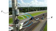
최근 무선통신 기술의 발전으로 인하여 차량(V)과 인프라 안테나(I) 간의 통신(V2I통신, 도 1 참고) 또는 차량(V)과 차량(V) 간의 통신(V2V통신, 도 2 참고) 또는 양자가 모두 가능한 차량과 다자간의 통신(V2X통신)기술이 제시되고 있다.The communication between the vehicle V and the infrastructure antenna I (V2I communication, see FIG. 1) or the communication between the vehicle V and the vehicle V (V2V communication, see FIG. 2) (V2X communication) technologies are proposed.
이러한 기술을 활용한 다양한 기능들이 차량에 탑재될 수 있을 것인데, 본 발명은 이 중 V2X통신을 활용한 사이드미러의 최적 조절에 관한 것이다.
Various functions utilizing such a technology may be mounted on a vehicle. The present invention relates to an optimal adjustment of a side mirror using the V2X communication.
차량의 사이드미러를 자동으로 조절하는 장치에 관하여는 일부 기술이 소개되고 있고, 그 중 KR10-2000-0033489 A의 경우 차량이 교차로에 진입하면 자이로 센서의 회전 각도에 따라 사이드 미러를 차량 진행방향으로 항상 일정하게 유지시킴으로써 사각지대에서의 사고 예방을 미연에 방지시켜 주는 것으로서 자이로센서를 이용한 사이드미러의 제어에 관한 것이다.Some of the technologies for automatic adjustment of the side mirrors of vehicles have been introduced. In the case of KR10-2000-0033489 A, when the vehicle enters the intersection, the side mirrors are moved in the vehicle traveling direction according to the rotation angle of the gyro sensor The present invention relates to control of a side mirror using a gyro sensor, which prevents an accident in a blind spot by preventing the occurrence of an accident.
그러나 이러한 기술은 차량의 선회시에만 적용될 수 있어 선회가 없는 교차로의 경우에 적용이 다소 어렵고, 또한, 자이로센서를 이용하는 경우에도 상대차량이 불규칙적인 운행양상을 보일 때에는 실질적으로 상대차량을 사이드미러에 담아내지 못하는 문제가 있었다.However, this technique can be applied only when turning the vehicle, so that it is somewhat difficult to apply to an intersection where there is no turning. Also, even when the gyro sensor is used, when the relative vehicle shows irregular running behavior, There was a problem that could not be covered.
따라서, 이러한 기술에서 더 나아가 V2X통신을 활용함으로써 실질적으로 상대차량을 효과적으로 사이드미러에 담아내는 기술이 필요하였던 것이다.
Therefore, in this technique, further, by utilizing V2X communication, it was necessary to effectively carry out the technique of effectively bringing the opponent vehicle into the side mirror.
상기의 배경기술로서 설명된 사항들은 본 발명의 배경에 대한 이해 증진을 위한 것일 뿐, 이 기술분야에서 통상의 지식을 가진자에게 이미 알려진 종래기술에 해당함을 인정하는 것으로 받아들여져서는 안 될 것이다.
It should be understood that the foregoing description of the background art is merely for the purpose of promoting an understanding of the background of the present invention and is not to be construed as an admission that the prior art is known to those skilled in the art.
본 발명은 이러한 문제점을 해결하기 위하여 제안된 것으로, V2X 통신을 활용하여 사이드미러의 조사각도를 최적으로 조절함으로써 운전자로 하여금 최적의 시야를 제공하고, 교차로에서의 사고를 예방할 수 있게 하는 사이드미러 조절방법 및 조절시스템을 제공하는데 그 목적이 있다.
SUMMARY OF THE INVENTION The present invention has been made in order to solve the above problems, and it is an object of the present invention to provide a side mirror control device capable of optimally adjusting an angle of illumination of a side mirror using V2X communication to provide an optimal view to a driver, A method and an adjustment system.
상기의 목적을 달성하기 위한 본 발명에 따른 사이드미러 조절방법은, 차량 무선통신을 통하여 자차가 교차지점에 근접하는지 판단하는 돌입단계; 차량 무선통신을 통하여 상대차량이 위험지역에 위치하는지 판단하는 위험단계; 운전자와 사이드미러 사이의 각도를 통해 사이드미러로 볼 수 있는 영역인 미러존을 계산하는 계산단계; 및 상대차량이 위험지역에 위치하는 경우 미러존에 존재할 수 있도록 사이드미러의 각도를 조절하는 조절단계;를 포함한다.According to another aspect of the present invention, there is provided a method of controlling a side mirror, the method comprising: a step of determining whether a vehicle is approaching an intersection through wireless communication; A risk step of determining whether the opponent vehicle is located in a dangerous area through vehicle wireless communication; A calculation step of calculating a mirror zone which is an area viewed by the side mirror through an angle between the driver and the side mirror; And an adjusting step of adjusting the angle of the side mirror so that the relative vehicle exists in the mirror zone when the opponent vehicle is located in the dangerous area.
상기 돌입단계는 자차가 진행하는 차선 중 교차지점에 근접하는 일정 영역을 합류지점으로 인식하고 자차가 합류지점에 위치하는지 여부를 통하여 자차가 교차지점에 근접하는지 판단할 수 있다.The rushing step recognizes a certain area near the intersection point of the lane on which the vehicle is traveling as a confluence point and can determine whether the vehicle is close to the intersection point through whether or not the vehicle is located at the confluence point.
상기 돌입단계는 차량과 인프라 안테나의 통신인 V2I통신을 통하여 자차가 교차지점에 근접하는지 판단할 수 있다.The launching step may determine whether the vehicle is approaching an intersection through V2I communication, which is communication between the vehicle and the infrastructure antenna.
상기 돌입단계는 자차의 GPS통신과 내비게이션 정보를 통하여 자차가 교차지점에 근접하는지 판단할 수 있다.The launching step can determine whether the vehicle is approaching an intersection through the GPS communication and the navigation information of the vehicle.
상기 위험지역은 자차가 합류할 상대차선 중 교차지점에 근접하는 일정 영역일 수 있다.The dangerous area may be a certain area that is close to an intersection of the opponent lanes to which the vehicle is to be joined.
상기 위험단계는 차량과 인프라 안테나의 통신인 V2I통신 또는 차량간의 통신인 V2V통신을 통하여 상대차량의 위치를 파악하고, 파악된 상대차량이 위험지역에 위치하는지 판단할 수 있다.The danger step may be to determine the position of the opponent vehicle through the V2I communication, which is the communication between the vehicle and the infrastructure antenna, or the V2V communication, which is the communication between the vehicles, and determine whether the detected opponent vehicle is located in the dangerous area.
상기 위험단계는, 상대차량이 위험지역에 위치하지 않는 경우 상대차량이 위험지역에 근접하는지 판단하는 예측단계;를 더 포함하고, 상기 조절단계는 상대차량이 위험지역에 근접하는 경우에도 사이드미러의 각도를 조절할 수 있다.Wherein the danger step further includes a prediction step of determining whether the opponent vehicle is close to a dangerous area when the opponent vehicle is not located in the dangerous area, The angle can be adjusted.
상기 계산단계는 운전자의 위치와 양측 사이드미러의 상대각도를 통하여 미러존을 계산할 수 있다.The calculating step may calculate the mirror zone through the position of the driver and the relative angle of the both side mirrors.
한편, 본 발명의 사이드미러 조절시스템은, 인프라 안테나 또는 상대차량과 무선통신을 수행할 수 있는 통신모듈; 사이드미러의 각도를 조절할 수 있는 구동모듈; 및 운전자와 사이드미러 사이의 각도를 통해 사이드미러로 볼 수 있는 영역인 미러존을 계산하고, 통신모듈을 통하여 자차가 교차지점에 근접하는지 판단하며 상대차량이 위험지역에 위치하는지 판단한 후, 상대차량이 위험지역에 위치하는 경우 상대차량이 미러존에 존재할 수 있도록 구동모듈을 제어하는 제어모듈;을 포함한다.
Meanwhile, the side mirror control system of the present invention includes: a communication module capable of performing wireless communication with an infrastructure antenna or a counterpart vehicle; A driving module capable of adjusting the angle of the side mirror; And a mirror zone which is an area visible by the side mirror through an angle between the driver and the side mirror, determines whether the vehicle is close to an intersection through the communication module, determines whether the opponent vehicle is located in a dangerous area, And a control module for controlling the drive module so that the relative vehicle exists in the mirror zone when the vehicle is located in the dangerous area.
상술한 바와 같은 구조로 이루어진 사이드미러 조절방법 및 조절시스템에 따르면, V2X 통신을 활용하여 사이드미러의 조사각도를 최적으로 조절함으로써 운전자로 하여금 최적의 시야를 제공하고, 교차로에서의 사고를 예방할 수 있게 된다.
According to the side mirror adjustment method and the adjustment system having the above-described structure, it is possible to optimize the angle of illumination of the side mirrors by utilizing the V2X communication, thereby providing the driver with an optimal view and preventing an accident at the intersection do.
도 1은 V2I 통신의 구성도.
도 2는 V2V 통신의 구성도.
도 3은 본 발명의 일 실시예에 따른 사이드미러 조절방법을 설명하기 위한 개념도.
도 4는 본 발명의 일 실시예에 따른 사이드미러 조절시스템의 구성도.
도 5는 본 발명의 일 실시예에 따른 사이드미러 조절방법의 순서도.1 is a block diagram of V2I communication.
2 is a block diagram of V2V communication.
3 is a conceptual diagram illustrating a side mirror adjustment method according to an embodiment of the present invention;
4 is a configuration diagram of a side mirror control system according to an embodiment of the present invention;
5 is a flowchart of a side mirror adjustment method according to an embodiment of the present invention.
이하에서는 첨부된 도면을 참조하여 본 발명의 바람직한 실시 예에 따른 사이드미러 조절방법 및 조절시스템에 대하여 살펴본다.Hereinafter, a side mirror adjusting method and an adjusting system according to preferred embodiments of the present invention will be described with reference to the accompanying drawings.
도 5는 본 발명의 일 실시예에 따른 사이드미러 조절방법의 순서도로서, 본 발명의 사이드미러 조절방법은, 차량 무선통신을 통하여 자차가 교차지점에 근접하는지 판단하는 돌입단계(S200); 차량 무선통신을 통하여 상대차량이 위험지역에 위치하는지 판단하는 위험단계(S400); 운전자와 사이드미러 사이의 각도를 통해 사이드미러로 볼 수 있는 영역인 미러존을 계산하는 계산단계(S100); 및 상대차량이 위험지역에 위치하는 경우 미러존에 존재할 수 있도록 사이드미러의 각도를 조절하는 조절단계(S500);를 포함한다.FIG. 5 is a flowchart illustrating a method of adjusting a side mirror according to an embodiment of the present invention. The method of adjusting a side mirror of the present invention includes an entering step S200 for determining whether a vehicle is approaching an intersection through vehicle wireless communication. A risk step (S400) for determining whether the opponent vehicle is located in a dangerous area through vehicle wireless communication; A calculation step (S100) of calculating a mirror zone which is an area visible by the side mirror through an angle between the driver and the side mirror; And an adjustment step (S500) of adjusting the angle of the side mirror so that the relative vehicle exists in the mirror zone when the vehicle is located in the dangerous area.
본 발명의 사이드미러 조절방법은 V2X통신을 이용한 조절방법으로서, 주로 교차로에서의 위험상황에 대비하기 위한 것이다. 교차로에서는 자차의 진입뿐만 아니라 상대차량의 예측불허의 차선변경 상황도 수반되기 때문에 사이드미러로 모든 영역을 커버하기 힘들고, 따라서 운전자는 교차로의 집입시 고개를 돌려 후방을 예의주시해야 하며 동시에 전방도 예의주시해야 하는 어려운 상황을 반복한다.The side mirror adjustment method of the present invention is a method of adjusting using V2X communication, mainly to prepare for a dangerous situation at an intersection. It is difficult to cover all areas with side mirrors because it involves not only the entry of the car but also the unpredicted lane changing situation of the opponent vehicle. Therefore, the driver must turn his / her head when observing the intersection to watch the rear, Repeat the difficult situation to watch.
또한, 이러한 교차로에서의 상황은 단순히 내비게이션의 정보만으로는 GPS 통신의 한계상 차량의 차선변경 상황까지 커버하지 못하기 때문에 좀 더 정확한 통신수단과 이를 이용한 정확한 판단에 근거하여 사이드미러를 조절할 필요가 있는 것이다.In addition, the situation at such an intersection can not cover the lane change situation of the vehicle due to the limitation of the GPS communication only by the information of the navigation, so it is necessary to adjust the side mirror based on more accurate communication means and accurate judgment using the communication means .
이를 위해 본 발명의 사이드미러 조절시스템은 크게, 인프라 안테나(I) 또는 상대차량(300)과 무선통신을 수행할 수 있는 통신모듈(120); 사이드미러(140)의 각도를 조절할 수 있는 구동모듈(142); 및 운전자(H)와 사이드미러(140) 사이의 각도를 통해 사이드미러(140)로 볼 수 있는 영역인 미러존(144)을 계산하고, 통신모듈(120)을 통하여 자차(100)가 교차지점에 근접하는지 판단하며 상대차량(300)이 위험지역(620)에 위치하는지 판단한 후, 상대차량(300)이 위험지역(620)에 위치하는 경우 상대차량(300)이 미러존(144)에 존재할 수 있도록 구동모듈(142)을 제어하는 제어모듈(150);을 포함한다.To this end, the side mirror control system of the present invention mainly comprises: a
도 4는 본 발명의 일 실시예에 따른 사이드미러 조절시스템의 구성도로서, 차량에는 다른 차량 혹은 인프라 안테나와 통신이 가능한 통신모듈(120)이 장착되고, 사이드미러(140)의 각도를 조절할 수 있는 구동모듈(142)이 구비된다.FIG. 4 is a block diagram of a side mirror control system according to an embodiment of the present invention. In the vehicle, a
그리고, 차량의 제어모듈은 운전자(H)와 사이드미러(140) 사이의 각도를 통해 사이드미러(140)로 볼 수 있는 영역인 미러존(144)을 계산한다. 이를 위해 운전자(H)의 위치는 시트의 중앙으로 추정할 수도 있겠지만 좀 더 정확하게는 차량 실내를 촬영하는 카메라(130)를 통해 운전자(H)의 정확한 위치를 알고, 그 지점을 중심으로 사이드미러(140)와의 상대각도(B,C)를 통해 사이드미러(140)의 조사영역인 미러존(144)을 계산할 수 있도록 함이 바람직하다.The control module of the vehicle calculates the
그리고 제어모듈(150)은 통신모듈(120)을 통하여 자차(100)가 교차지점에 근접하는지 판단하며 상대차량(300)이 위험지역(620)에 위치하는지 판단한 후, 상대차량(300)이 위험지역(620)에 위치하는 경우 상대차량(300)이 미러존(144)에 존재할 수 있도록 구동모듈(142)을 제어하는 것이다.
The
구체적으로, 도 3은 본 발명의 일 실시예에 따른 사이드미러 조절방법을 설명하기 위한 개념도로서, 도로에서 현재 자차(100)의 운행차선(500)과 상대차선(600)이 교차하는 교차지점이 있다고 할 때, 자차(100)는 우선 앞서 살핀 방법으로 자차(100)의 미러존(144)을 계산한다. 그리고 자차(100)가 교차지점에 근접한 합류지점(520)에 들어오는지 판단한 후 자차(100)가 합류지점(520)에 들어온 경우 상대차량(300)을 파악한다.3 is a conceptual diagram for explaining a method of adjusting a side mirror according to an embodiment of the present invention. The intersection point where the
상대차량(300)이 상대차선(600) 중 교차지점에 근접한 위험지역(620)에 들어온 경우 그 상대차량(300)을 추종하도록 사이드미러를 제어하는데, 이를 위해 정확한 자차(100)와 상대차량(300) 간의 상대위치를 알 필요가 있다. 이를 위해 자차(100)와 상대차량(300)이 모두 인프라 안테나(I)와 통신하여 V2I통신을 통해 자차(100)와 인프라 안테나(I), 상대차량(300) 간의 거리(d1,d2,d3)를 알고 그 사이에서 이루는 각도(A)를 알 수 있게 된다. 이를 통해 상대차량(300)의 위치를 파악하고 자차(100)에서는 미러존(144)에 상대차량이 위치할 수 있도록 사이드미러를 조절하는 것이다.
When the
도 5는 본 발명의 일 실시예에 따른 사이드미러 조절방법의 순서도로서 ,본 발명의 사이드미러 조절방법은, 차량 무선통신을 통하여 자차가 교차지점에 근접하는지 판단하는 돌입단계(S200); 차량 무선통신을 통하여 상대차량이 위험지역에 위치하는지 판단하는 위험단계(S400); 운전자와 사이드미러 사이의 각도를 통해 사이드미러로 볼 수 있는 영역인 미러존을 계산하는 계산단계(S100); 및 상대차량이 위험지역에 위치하는 경우 미러존에 존재할 수 있도록 사이드미러의 각도를 조절하는 조절단계(S500);를 포함한다.FIG. 5 is a flowchart illustrating a method of adjusting a side mirror according to an embodiment of the present invention. The method of adjusting a side mirror of the present invention includes an entering step S200 for determining whether a vehicle is approaching an intersection through vehicle wireless communication. A risk step (S400) for determining whether the opponent vehicle is located in a dangerous area through vehicle wireless communication; A calculation step (S100) of calculating a mirror zone which is an area visible by the side mirror through an angle between the driver and the side mirror; And an adjustment step (S500) of adjusting the angle of the side mirror so that the relative vehicle exists in the mirror zone when the vehicle is located in the dangerous area.
또한, 상기 돌입단계(S200)는 자차가 진행하는 차선 중 교차지점에 근접하는 일정 영역을 합류지점으로 인식하고 자차가 합류지점에 위치하는지 여부를 통하여 자차가 교차지점에 근접하는지 판단하도록 한다.In addition, the entry step S200 recognizes a certain area near the intersection of the lane on which the vehicle is traveling as a confluence point, and determines whether the vehicle is close to the intersection through whether or not the vehicle is located at the confluence point.
자차가 교차지점에 근접하는지를 판단하는 돌입단계(S200)는 차량과 인프라 안테나의 통신인 V2I통신을 통하여 자차가 교차지점에 근접하는지 판단할 수 있으며, 또는 돌입단계(S200)는 자차의 GPS통신과 내비게이션 정보를 통하여 자차가 교차지점에 근접하는지 판단할 수도 있을 것이다.
The step S200 of determining whether the vehicle is approaching the intersection can determine whether the vehicle is approaching the intersection through the V2I communication which is the communication between the vehicle and the infrastructure antenna. The navigation information may determine whether the vehicle is approaching the intersection.
한편, 자차가 교차지점에 근접한 경우에는 V2I 통신을 이용하여 상대차량의 위치를 파악하고, 파악된 상대차량이 위험지역에 위치하는지 판단한다(S300,S400). 그리고 추가적으로는 V2V통신을 통하여 상대차량의 위치를 파악하고(S600,S700), 파악된 상대차량이 위험지역에 위치하는지 판단함으로써 인프라 안테나의 고장이나 없는 경우를 대비하도록 할 것이다.If the vehicle is close to the intersection, the position of the opponent vehicle is determined using the V2I communication, and it is determined whether the detected opponent vehicle is located in the dangerous area (S300, S400). In addition, the position of the opponent vehicle is further determined through the V2V communication (S600, S700), and it is determined whether the detected opponent vehicle is located in the dangerous area, so as to prepare for the failure or the absence of the infrastructure antenna.
이러한 V2X통신을 통하여 상대차량을 탐지한 후에는 그 통신 데이터를 계산하여 정확한 상대차량의 궤적과 현재 위치를 파악한다.After detecting the opponent vehicle through the V2X communication, the communication data is calculated and the accurate locus of the opponent vehicle and the current position are obtained.
그리고 이를 위해 상대차량을 탐지하는 기준인 위험지역은 자차가 합류할 상대차선 중 교차지점에 근접하는 일정 영역으로 선정한다.
For this purpose, the hazardous area, which is the criterion for detecting the opponent vehicle, is selected as a certain area near the intersection of the relative lanes to which the vehicle is to be joined.
한편, 상기 위험단계(S400)는, 상대차량이 위험지역에 위치하지 않는 경우 상대차량이 위험지역에 근접하는지 판단하는 예측단계(S700);를 더 포함하고, 상기 조절단계(S500)는 상대차량이 위험지역에 근접하는 경우에도 사이드미러의 각도를 조절하도록 함으로써 도 3에 도시된 차선변경 차량(400)의 경우에도 고위험군으로 분류하여 사이드미러를 통해 볼 수 있도록 할 것이다. 이러한 경우는 내비게이션의 정보만으로는 확보할 수 없는 경우이고 특히, 본 발명의 경우 레이더 장비를 이용한 상대차량의 탐지보다 장애물의 존재를 가정할 때 더욱 정확도가 높은 것이다. 일반적으로 산간지역의 교차로에는 교차지점 사이에 나무 등의 장애물이 있는 경우도 있기 때문이다.
The danger step S400 further includes a prediction step S700 of determining whether the opponent vehicle is close to a dangerous area when the opponent vehicle is not located in the dangerous area, Even in the case of approaching this dangerous area, by adjusting the angle of the side mirrors, the lane-changing
그리고 상대차량이 위험지역에 위치하는 경우 미러존에 존재할 수 있도록 사이드미러의 각도를 조절하는 조절단계(S500);를 수행하여 상대차량이 사이드미러에 보이도록 함으로써 안전운전을 돕고, 특히 상대차량이 차선변경하여 갑자기 들어오거나 차속이 빨라 순식간에 들어오거나 교차지점에 장애물이 있는 경우에도 V2X통신을 통하여 정확하게 상대차량을 예측할 수 있는 것이다.
And adjusting the angle of the side mirror so that the relative vehicle is located in the mirror zone when the opponent vehicle is located in the danger zone, performing the step S500 so that the opponent vehicle is seen on the side mirror, V2X communication can accurately predict the opponent vehicle even if the lane change suddenly comes in, or the speed of the vehicle suddenly comes in or there is an obstacle at the crossing point.
본 발명은 특정한 실시예에 관련하여 도시하고 설명하였지만, 이하의 특허청구범위에 의해 제공되는 본 발명의 기술적 사상을 벗어나지 않는 한도 내에서, 본 발명이 다양하게 개량 및 변화될 수 있다는 것은 당 업계에서 통상의 지식을 가진 자에게 있어서 자명할 것이다.
While the present invention has been particularly shown and described with reference to specific embodiments thereof, it will be understood by those skilled in the art that various changes in form and details may be made therein without departing from the spirit and scope of the invention as defined by the following claims It will be apparent to those of ordinary skill in the art.
100 : 자차 120 : 통신모듈
140 : 사이드미러 144 : 미러존
150 : 제어모듈 300 : 상대차량
S100 : 계산단계 S200 : 돌입단계
S400 : 위험단계 S500 : 조절단계100: car 120: communication module
140: Side mirror 144: Mirror zone
150: Control module 300: Relative vehicle
S100: Calculation step S200: Ingress step
S400: Risk step S500: Adjustment step
Claims (9)
Translated fromKorean상기 자차, 상기 교차 지점에 접근하는 상대 차량 및 인프라 안테나 간의 V2I 통신을 통하여 상기 상대 차량, 자차 및 인프라 안테나 간의 거리를 구하고, 상기 인프라 안테나를 기준으로 상기 상대 차량과 상기 자차가 이루는 각도를 산출하여 상기 상대 차량의 위치가 위험지역에 위치하는지 여부를 판단하는 단계;
운전자의 위치와 양측 사이드미러의 상대 각도를 통해 사이드미러로 볼 수 있는 영역인 미러존을 계산하는 계산단계(S100); 및
상대차량이 위험지역에 위치하는 경우 미러존에 존재할 수 있도록 사이드미러의 각도를 조절하는 조절단계(S500);를 포함하는,
사이드미러 조절방법.A step of determining whether the vehicle is approaching an intersection through a vehicle wireless communication;
A distance between the vehicle, the vehicle, and the infrastructure antenna is obtained through V2I communication between the vehicle, the vehicle approaching the intersection, and the infrastructure antenna, and the angle between the vehicle and the vehicle is calculated based on the infrastructure antenna Determining whether the position of the opponent vehicle is located in a dangerous area;
A calculation step (S100) of calculating a mirror zone which is an area viewed by a side mirror through a position of a driver and a relative angle of both side mirrors; And
(S500) of adjusting the angle of the side mirror so that the vehicle is located in the mirror zone when the opponent vehicle is located in the danger zone.
How to adjust the side mirrors.
상기 돌입단계(S200)는 자차가 진행하는 차선 중 교차지점에 근접하는 일정 영역을 합류지점으로 인식하고 자차가 합류지점에 위치하는지 여부를 통하여 자차가 교차지점에 근접하는지 판단하는 것을 특징으로 하는 사이드미러 조절방법.The method according to claim 1,
The step S200 recognizes a certain area near the intersection point of the lane on which the vehicle is traveling as a confluence point and determines whether the vehicle is close to the intersection through whether or not the vehicle is located at the confluence point. How to adjust the mirror.
상기 돌입단계(S200)는 차량과 인프라 안테나의 통신인 V2I통신을 통하여 자차가 교차지점에 근접하는지 판단하는 것을 특징으로 하는 사이드미러 조절방법.The method according to claim 1,
Wherein the step S200 determines whether the vehicle is approaching an intersection through V2I communication which is communication between the vehicle and the infrastructure antenna.
상기 돌입단계(S200)는 자차의 GPS통신과 내비게이션 정보를 통하여 자차가 교차지점에 근접하는지 판단하는 것을 특징으로 하는 사이드미러 조절방법.The method according to claim 1,
Wherein the step S200 determines whether the vehicle is approaching an intersection through the GPS communication and the navigation information of the vehicle.
상기 위험지역은 자차가 합류할 상대차선 중 교차지점에 근접하는 일정 영역인 것을 특징으로 하는 사이드미러 조절방법.The method according to claim 1,
Wherein the dangerous area is a predetermined area that is close to an intersection point of a lane on which the vehicle is to be joined.
상기 상대 차량의 위치가 위험지역에 위치하는지 여부를 판단하는 단계는, 상대차량이 위험지역에 위치하지 않는 경우 상대차량이 위험지역에 근접하는지 판단하는 예측단계(S700);를 더 포함하고,
상기 조절단계(S500)는 상대차량이 위험지역에 근접하는 경우에도 사이드미러의 각도를 조절하는 것을 특징으로 하는 사이드미러 조절방법.The method according to claim 1,
Wherein the step of determining whether the position of the opponent vehicle is located in a dangerous area includes the step of predicting whether the opponent vehicle is in a dangerous area when the opponent vehicle is not located in the dangerous area,
Wherein the adjusting step S500 adjusts the angle of the side mirror even when the opponent vehicle is close to the dangerous area.
사이드미러(140)의 각도를 조절할 수 있는 구동모듈(142); 및
운전자(H)와 사이드미러(140) 사이의 각도를 통해 사이드미러(140)로 볼 수 있는 영역인 미러존(144)을 계산하고, 통신모듈(120)을 통하여 자차(100)가 교차 지점에 근접하는지 판단하며, 상기 자차, 상대 차량 및 인프라 안테나 간의 V2I 통신을 통하여 상기 상대 차량, 자차 및 인프라 안테나 간의 거리를 구하고, 상기 인프라 안테나를 기준으로 상기 상대 차량과 상기 자차가 이루는 각도를 산출하여 상기 상대 차량이 위험지역에 위치하는지 여부를 판단한 후, 상대차량(300)이 위험지역(620)에 위치하는 경우 상대차량(300)이 미러존(144)에 존재할 수 있도록 구동모듈(142)을 제어하는 제어모듈(150);을 포함하는 사이드미러 조절시스템.A communication module (120) capable of performing wireless communication with the infrastructure antenna (I) or the counterpart vehicle (300);
A driving module 142 capable of adjusting the angle of the side mirror 140; And
The mirror zone 144 which is an area visible to the side mirror 140 through the angle between the driver H and the side mirror 140 is calculated and the vehicle 100 is positioned at the crossing point via the communication module 120 Determining a distance between the counterpart vehicle, the vehicle and the infrastructure antenna through V2I communication between the vehicle, the counterpart vehicle, and the infrastructure antenna, calculating an angle between the counterpart vehicle and the vehicle based on the infrastructure antenna, The driving module 142 is controlled so that the opponent vehicle 300 may exist in the mirror zone 144 when the opponent vehicle 300 is located in the dangerous area 620 after determining whether or not the opponent vehicle is located in the dangerous area. And a control module (150) for controlling the side mirrors.
Priority Applications (4)
| Application Number | Priority Date | Filing Date | Title |
|---|---|---|---|
| KR20120118108AKR101481229B1 (en) | 2012-10-23 | 2012-10-23 | Method and system for adjusting side-mirror |
| US13/693,580US20140114500A1 (en) | 2012-10-23 | 2012-12-04 | Method and system for adjusting side mirror |
| DE102012223412.8ADE102012223412A1 (en) | 2012-10-23 | 2012-12-17 | Method and system for adjusting a side mirror |
| CN201210598987.2ACN103770711A (en) | 2012-10-23 | 2012-12-21 | Method and system for adjusting side mirror |
Applications Claiming Priority (1)
| Application Number | Priority Date | Filing Date | Title |
|---|---|---|---|
| KR20120118108AKR101481229B1 (en) | 2012-10-23 | 2012-10-23 | Method and system for adjusting side-mirror |
Publications (2)
| Publication Number | Publication Date |
|---|---|
| KR20140051724A KR20140051724A (en) | 2014-05-02 |
| KR101481229B1true KR101481229B1 (en) | 2015-01-09 |
Family
ID=50437091
Family Applications (1)
| Application Number | Title | Priority Date | Filing Date |
|---|---|---|---|
| KR20120118108AActiveKR101481229B1 (en) | 2012-10-23 | 2012-10-23 | Method and system for adjusting side-mirror |
Country Status (4)
| Country | Link |
|---|---|
| US (1) | US20140114500A1 (en) |
| KR (1) | KR101481229B1 (en) |
| CN (1) | CN103770711A (en) |
| DE (1) | DE102012223412A1 (en) |
Cited By (1)
| Publication number | Priority date | Publication date | Assignee | Title |
|---|---|---|---|---|
| US10086764B2 (en) | 2015-10-12 | 2018-10-02 | Hyundai Motor Company | Apparatus and method for controlling a viewing angle for a vehicle, and a vehicle including the apparatus |
Families Citing this family (13)
| Publication number | Priority date | Publication date | Assignee | Title |
|---|---|---|---|---|
| US9041552B2 (en)* | 2012-01-10 | 2015-05-26 | Xiao Lin Yu | Automobile blind spot detection system and method |
| CN114710351B (en)* | 2014-03-26 | 2025-05-20 | 大陆汽车科技有限公司 | Method and system for improving data security during communication |
| CN105015423B (en)* | 2015-07-20 | 2017-09-26 | 北京汽车股份有限公司 | Rear mirror control method, rearview mirror control system and automobile |
| CN105383393B (en)* | 2015-12-22 | 2017-06-30 | 深圳市歌美迪电子技术发展有限公司 | Multimedia rear-view mirror system and its mirror-reflection area size adjusting method |
| SE539981C2 (en) | 2016-06-28 | 2018-02-20 | Scania Cv Ab | Method and control unit for a digital mirror |
| US10220785B2 (en)* | 2017-03-24 | 2019-03-05 | Ford Global Technologies, Llc | Controlling side-view mirrors in autonomous vehicles |
| US10220786B2 (en)* | 2017-03-24 | 2019-03-05 | Ford Global Technologies, Llc | Controlling side-view mirrors in autonomous vehicles |
| US10902728B2 (en) | 2017-04-26 | 2021-01-26 | Ford Global Technologies, Llc | Blind spot object detection |
| KR102696501B1 (en)* | 2019-09-05 | 2024-08-19 | 현대모비스 주식회사 | Mehtod for generating avoidance path and electronic device thereof |
| CN112498243A (en)* | 2020-11-12 | 2021-03-16 | 浙江合众新能源汽车有限公司 | Self-adaptive adjusting method and device for exterior rearview mirror |
| KR20230073380A (en)* | 2021-11-18 | 2023-05-26 | 현대자동차주식회사 | Vehicle and method for controlling |
| CN116101166A (en)* | 2022-11-30 | 2023-05-12 | 东风商用车有限公司 | Rearview mirror control method, device, equipment and readable storage medium |
| KR102735697B1 (en)* | 2022-12-20 | 2024-11-28 | 주식회사 현대케피코 | Vehicle control apparatus and method |
Citations (4)
| Publication number | Priority date | Publication date | Assignee | Title |
|---|---|---|---|---|
| JPH08263793A (en)* | 1995-03-23 | 1996-10-11 | Honda Motor Co Ltd | Vehicle control device |
| JP2005199910A (en) | 2004-01-16 | 2005-07-28 | Nissan Motor Co Ltd | Mirror control device for vehicle and mirror control method for vehicle |
| JP2010228540A (en)* | 2009-03-26 | 2010-10-14 | Denso Corp | Obstacle visual recognition device |
| KR20120123899A (en)* | 2011-05-02 | 2012-11-12 | 현대모비스 주식회사 | Apparatus And Method Recognizing State Of Circumstance For Car |
Family Cites Families (13)
| Publication number | Priority date | Publication date | Assignee | Title |
|---|---|---|---|---|
| US5668675A (en)* | 1995-01-18 | 1997-09-16 | Fredricks; Ronald J. | Opto-electronic aid for alignment of exterior vehicle mirrors to minimize blind spot effects |
| US7426437B2 (en)* | 1997-10-22 | 2008-09-16 | Intelligent Technologies International, Inc. | Accident avoidance systems and methods |
| KR20000004717U (en)* | 1998-08-14 | 2000-03-15 | 안문휘 | Reflector auto-adjustment side mirror |
| KR20000033489A (en) | 1998-11-24 | 2000-06-15 | 김영환 | Method and device for adjusting side mirror when driving a vehicle |
| US6193380B1 (en)* | 1999-04-20 | 2001-02-27 | Raymond A. Jacobs | Vehicle blind spot mirror |
| US6501371B2 (en)* | 2001-05-22 | 2002-12-31 | Trw Inc. | Apparatus and method for positioning a reflective surface on a vehicle |
| US6672728B1 (en)* | 2001-09-04 | 2004-01-06 | Exon Science Inc. | Exterior rearview mirror with automatically adjusted view angle |
| US7571041B2 (en)* | 2005-01-13 | 2009-08-04 | General Motors Corporation | Automatic control of automotive rearview mirror |
| JP4810953B2 (en)* | 2005-10-07 | 2011-11-09 | 日産自動車株式会社 | Blind spot image display device for vehicles |
| US20100220406A1 (en)* | 2008-03-31 | 2010-09-02 | Ford Global Technologies, Llc | Blind Spot Detection System |
| US7994902B2 (en)* | 2009-02-25 | 2011-08-09 | Southwest Research Institute | Cooperative sensor-sharing vehicle traffic safety system |
| JP5613398B2 (en)* | 2009-10-29 | 2014-10-22 | 富士重工業株式会社 | Intersection driving support device |
| SE535786C2 (en)* | 2010-01-19 | 2012-12-18 | Volvo Technology Corp | Dead Angle Warning System |
- 2012
- 2012-10-23KRKR20120118108Apatent/KR101481229B1/enactiveActive
- 2012-12-04USUS13/693,580patent/US20140114500A1/ennot_activeAbandoned
- 2012-12-17DEDE102012223412.8Apatent/DE102012223412A1/ennot_activeWithdrawn
- 2012-12-21CNCN201210598987.2Apatent/CN103770711A/enactivePending
Patent Citations (4)
| Publication number | Priority date | Publication date | Assignee | Title |
|---|---|---|---|---|
| JPH08263793A (en)* | 1995-03-23 | 1996-10-11 | Honda Motor Co Ltd | Vehicle control device |
| JP2005199910A (en) | 2004-01-16 | 2005-07-28 | Nissan Motor Co Ltd | Mirror control device for vehicle and mirror control method for vehicle |
| JP2010228540A (en)* | 2009-03-26 | 2010-10-14 | Denso Corp | Obstacle visual recognition device |
| KR20120123899A (en)* | 2011-05-02 | 2012-11-12 | 현대모비스 주식회사 | Apparatus And Method Recognizing State Of Circumstance For Car |
Cited By (1)
| Publication number | Priority date | Publication date | Assignee | Title |
|---|---|---|---|---|
| US10086764B2 (en) | 2015-10-12 | 2018-10-02 | Hyundai Motor Company | Apparatus and method for controlling a viewing angle for a vehicle, and a vehicle including the apparatus |
Also Published As
| Publication number | Publication date |
|---|---|
| DE102012223412A1 (en) | 2014-04-24 |
| KR20140051724A (en) | 2014-05-02 |
| CN103770711A (en) | 2014-05-07 |
| US20140114500A1 (en) | 2014-04-24 |
Similar Documents
| Publication | Publication Date | Title |
|---|---|---|
| KR101481229B1 (en) | Method and system for adjusting side-mirror | |
| US11008009B2 (en) | Vehicle control device | |
| US10549780B2 (en) | Driving assistance device for a vehicle | |
| US10429848B2 (en) | Automatic driving system | |
| JP6361567B2 (en) | Automated driving vehicle system | |
| US10095227B2 (en) | Automatic driving system | |
| EP3091338B1 (en) | Misrecognition determination device | |
| JP6269534B2 (en) | Travel control device | |
| EP3611069A1 (en) | Vehicle control device | |
| EP3828502B1 (en) | Computer-implemented method and apparatus for detecting spoofing attacks on automated driving systems | |
| US10657822B2 (en) | Vehicle control device | |
| KR102691753B1 (en) | Autonomous driving apparatus and method | |
| JPH11328584A (en) | Vehicles group formation control device | |
| EP3842315B1 (en) | Autonomous driving vehicle three-point turn | |
| JP2018118609A (en) | Automated driving system | |
| US11577758B2 (en) | Autonomous vehicle park-and-go scenario design | |
| KR102691754B1 (en) | Autonomous driving apparatus and method | |
| JP7220244B2 (en) | VEHICLE CONTROL DEVICE, VEHICLE CONTROL METHOD, AND PROGRAM | |
| US12091057B2 (en) | Vehicle control device, vehicle control method, and storage medium | |
| US12036984B2 (en) | Vehicle travel control apparatus | |
| US12403911B2 (en) | Control device, control method, and storage medium | |
| US12371015B2 (en) | Vehicle control apparatus | |
| US11807274B2 (en) | L4 auto-emergency light system for future harsh brake |
Legal Events
| Date | Code | Title | Description |
|---|---|---|---|
| A201 | Request for examination | ||
| PA0109 | Patent application | Patent event code:PA01091R01D Comment text:Patent Application Patent event date:20121023 | |
| PA0201 | Request for examination | ||
| E902 | Notification of reason for refusal | ||
| PE0902 | Notice of grounds for rejection | Comment text:Notification of reason for refusal Patent event date:20131031 Patent event code:PE09021S01D | |
| PG1501 | Laying open of application | ||
| E90F | Notification of reason for final refusal | ||
| PE0902 | Notice of grounds for rejection | Comment text:Final Notice of Reason for Refusal Patent event date:20140528 Patent event code:PE09021S02D | |
| E701 | Decision to grant or registration of patent right | ||
| PE0701 | Decision of registration | Patent event code:PE07011S01D Comment text:Decision to Grant Registration Patent event date:20141126 | |
| GRNT | Written decision to grant | ||
| PR0701 | Registration of establishment | Comment text:Registration of Establishment Patent event date:20150105 Patent event code:PR07011E01D | |
| PR1002 | Payment of registration fee | Payment date:20150105 End annual number:3 Start annual number:1 | |
| PG1601 | Publication of registration | ||
| FPAY | Annual fee payment | Payment date:20171227 Year of fee payment:4 | |
| PR1001 | Payment of annual fee | Payment date:20171227 Start annual number:4 End annual number:4 | |
| FPAY | Annual fee payment | Payment date:20181213 Year of fee payment:5 | |
| PR1001 | Payment of annual fee | Payment date:20181213 Start annual number:5 End annual number:5 | |
| PR1001 | Payment of annual fee | Payment date:20210104 Start annual number:7 End annual number:7 |