KR101480514B1 - Stent for cerebral aneurysm coil embolization - Google Patents
Stent for cerebral aneurysm coil embolizationDownload PDFInfo
- Publication number
- KR101480514B1 KR101480514B1KR20120054628AKR20120054628AKR101480514B1KR 101480514 B1KR101480514 B1KR 101480514B1KR 20120054628 AKR20120054628 AKR 20120054628AKR 20120054628 AKR20120054628 AKR 20120054628AKR 101480514 B1KR101480514 B1KR 101480514B1
- Authority
- KR
- South Korea
- Prior art keywords
- stent
- cerebral
- aneurysm
- cerebral aneurysm
- central portion
- Prior art date
- Legal status (The legal status is an assumption and is not a legal conclusion. Google has not performed a legal analysis and makes no representation as to the accuracy of the status listed.)
- Active
Links
- 201000008450Intracranial aneurysmDiseases0.000titleclaimsabstractdescription94
- 230000010102embolizationEffects0.000titleclaimsabstractdescription36
- 229910052751metalInorganic materials0.000claimsabstractdescription12
- 239000002184metalSubstances0.000claimsabstractdescription12
- 238000000034methodMethods0.000claimsdescription12
- 239000000463materialSubstances0.000claimsdescription4
- 206010002329AneurysmDiseases0.000abstractdescription38
- 210000001627cerebral arteryAnatomy0.000description47
- 210000004204blood vesselAnatomy0.000description29
- 239000003550markerSubstances0.000description19
- 230000002490cerebral effectEffects0.000description9
- 238000010586diagramMethods0.000description7
- 210000001367arteryAnatomy0.000description6
- 230000006870functionEffects0.000description5
- 229910001285shape-memory alloyInorganic materials0.000description5
- 210000001841basilar arteryAnatomy0.000description4
- 238000003780insertionMethods0.000description3
- 230000037431insertionEffects0.000description3
- 238000011282treatmentMethods0.000description3
- 229910001111Fine metalInorganic materials0.000description2
- 230000000694effectsEffects0.000description2
- 238000013161embolization procedureMethods0.000description2
- 229910001000nickel titaniumInorganic materials0.000description2
- HLXZNVUGXRDIFK-UHFFFAOYSA-Nnickel titaniumChemical compound[Ti].[Ti].[Ti].[Ti].[Ti].[Ti].[Ti].[Ti].[Ti].[Ti].[Ti].[Ni].[Ni].[Ni].[Ni].[Ni].[Ni].[Ni].[Ni].[Ni].[Ni].[Ni].[Ni].[Ni].[Ni]HLXZNVUGXRDIFK-UHFFFAOYSA-N0.000description2
- 239000011800void materialSubstances0.000description2
- 206010008111Cerebral haemorrhageDiseases0.000description1
- 229910000990Ni alloyInorganic materials0.000description1
- 229910001069Ti alloyInorganic materials0.000description1
- RTAQQCXQSZGOHL-UHFFFAOYSA-NTitaniumChemical compound[Ti]RTAQQCXQSZGOHL-UHFFFAOYSA-N0.000description1
- 230000000903blocking effectEffects0.000description1
- 210000004369bloodAnatomy0.000description1
- 239000008280bloodSubstances0.000description1
- 230000017531blood circulationEffects0.000description1
- 230000036760body temperatureEffects0.000description1
- 210000005013brain tissueAnatomy0.000description1
- 230000001112coagulating effectEffects0.000description1
- 210000004351coronary vesselAnatomy0.000description1
- 238000007428craniotomyMethods0.000description1
- 239000013078crystalSubstances0.000description1
- 230000007423decreaseEffects0.000description1
- 230000002950deficientEffects0.000description1
- 201000010099diseaseDiseases0.000description1
- 208000037265diseases, disorders, signs and symptomsDiseases0.000description1
- 210000001105femoral arteryAnatomy0.000description1
- 238000009434installationMethods0.000description1
- 238000010030laminatingMethods0.000description1
- 230000005012migrationEffects0.000description1
- 238000013508migrationMethods0.000description1
- 230000003287optical effectEffects0.000description1
- 210000003101oviductAnatomy0.000description1
- 210000005259peripheral bloodAnatomy0.000description1
- 239000011886peripheral bloodSubstances0.000description1
- 230000002093peripheral effectEffects0.000description1
- 230000005855radiationEffects0.000description1
- 238000004904shorteningMethods0.000description1
- 210000003625skullAnatomy0.000description1
- 238000001356surgical procedureMethods0.000description1
- 230000002459sustained effectEffects0.000description1
- 239000010936titaniumSubstances0.000description1
- 210000005166vasculatureAnatomy0.000description1
Images


Classifications
- A—HUMAN NECESSITIES
- A61—MEDICAL OR VETERINARY SCIENCE; HYGIENE
- A61F—FILTERS IMPLANTABLE INTO BLOOD VESSELS; PROSTHESES; DEVICES PROVIDING PATENCY TO, OR PREVENTING COLLAPSING OF, TUBULAR STRUCTURES OF THE BODY, e.g. STENTS; ORTHOPAEDIC, NURSING OR CONTRACEPTIVE DEVICES; FOMENTATION; TREATMENT OR PROTECTION OF EYES OR EARS; BANDAGES, DRESSINGS OR ABSORBENT PADS; FIRST-AID KITS
- A61F2/00—Filters implantable into blood vessels; Prostheses, i.e. artificial substitutes or replacements for parts of the body; Appliances for connecting them with the body; Devices providing patency to, or preventing collapsing of, tubular structures of the body, e.g. stents
- A61F2/82—Devices providing patency to, or preventing collapsing of, tubular structures of the body, e.g. stents
- A61F2/86—Stents in a form characterised by the wire-like elements; Stents in the form characterised by a net-like or mesh-like structure
- A61F2/90—Stents in a form characterised by the wire-like elements; Stents in the form characterised by a net-like or mesh-like structure characterised by a net-like or mesh-like structure
- A—HUMAN NECESSITIES
- A61—MEDICAL OR VETERINARY SCIENCE; HYGIENE
- A61F—FILTERS IMPLANTABLE INTO BLOOD VESSELS; PROSTHESES; DEVICES PROVIDING PATENCY TO, OR PREVENTING COLLAPSING OF, TUBULAR STRUCTURES OF THE BODY, e.g. STENTS; ORTHOPAEDIC, NURSING OR CONTRACEPTIVE DEVICES; FOMENTATION; TREATMENT OR PROTECTION OF EYES OR EARS; BANDAGES, DRESSINGS OR ABSORBENT PADS; FIRST-AID KITS
- A61F2/00—Filters implantable into blood vessels; Prostheses, i.e. artificial substitutes or replacements for parts of the body; Appliances for connecting them with the body; Devices providing patency to, or preventing collapsing of, tubular structures of the body, e.g. stents
- A61F2/02—Prostheses implantable into the body
- A61F2/04—Hollow or tubular parts of organs, e.g. bladders, tracheae, bronchi or bile ducts
- A61F2/06—Blood vessels
- A61F2/07—Stent-grafts
- A—HUMAN NECESSITIES
- A61—MEDICAL OR VETERINARY SCIENCE; HYGIENE
- A61B—DIAGNOSIS; SURGERY; IDENTIFICATION
- A61B17/00—Surgical instruments, devices or methods
- A61B17/12—Surgical instruments, devices or methods for ligaturing or otherwise compressing tubular parts of the body, e.g. blood vessels or umbilical cord
- A61B17/12022—Occluding by internal devices, e.g. balloons or releasable wires
- A61B17/12099—Occluding by internal devices, e.g. balloons or releasable wires characterised by the location of the occluder
- A61B17/12109—Occluding by internal devices, e.g. balloons or releasable wires characterised by the location of the occluder in a blood vessel
- A61B17/12113—Occluding by internal devices, e.g. balloons or releasable wires characterised by the location of the occluder in a blood vessel within an aneurysm
- A61B17/12118—Occluding by internal devices, e.g. balloons or releasable wires characterised by the location of the occluder in a blood vessel within an aneurysm for positioning in conjunction with a stent
- A—HUMAN NECESSITIES
- A61—MEDICAL OR VETERINARY SCIENCE; HYGIENE
- A61B—DIAGNOSIS; SURGERY; IDENTIFICATION
- A61B17/00—Surgical instruments, devices or methods
- A61B17/12—Surgical instruments, devices or methods for ligaturing or otherwise compressing tubular parts of the body, e.g. blood vessels or umbilical cord
- A61B17/12022—Occluding by internal devices, e.g. balloons or releasable wires
- A61B17/12131—Occluding by internal devices, e.g. balloons or releasable wires characterised by the type of occluding device
- A61B17/1214—Coils or wires
- A—HUMAN NECESSITIES
- A61—MEDICAL OR VETERINARY SCIENCE; HYGIENE
- A61L—METHODS OR APPARATUS FOR STERILISING MATERIALS OR OBJECTS IN GENERAL; DISINFECTION, STERILISATION OR DEODORISATION OF AIR; CHEMICAL ASPECTS OF BANDAGES, DRESSINGS, ABSORBENT PADS OR SURGICAL ARTICLES; MATERIALS FOR BANDAGES, DRESSINGS, ABSORBENT PADS OR SURGICAL ARTICLES
- A61L31/00—Materials for other surgical articles, e.g. stents, stent-grafts, shunts, surgical drapes, guide wires, materials for adhesion prevention, occluding devices, surgical gloves, tissue fixation devices
- A61L31/02—Inorganic materials
- A61L31/022—Metals or alloys
- A—HUMAN NECESSITIES
- A61—MEDICAL OR VETERINARY SCIENCE; HYGIENE
- A61F—FILTERS IMPLANTABLE INTO BLOOD VESSELS; PROSTHESES; DEVICES PROVIDING PATENCY TO, OR PREVENTING COLLAPSING OF, TUBULAR STRUCTURES OF THE BODY, e.g. STENTS; ORTHOPAEDIC, NURSING OR CONTRACEPTIVE DEVICES; FOMENTATION; TREATMENT OR PROTECTION OF EYES OR EARS; BANDAGES, DRESSINGS OR ABSORBENT PADS; FIRST-AID KITS
- A61F2/00—Filters implantable into blood vessels; Prostheses, i.e. artificial substitutes or replacements for parts of the body; Appliances for connecting them with the body; Devices providing patency to, or preventing collapsing of, tubular structures of the body, e.g. stents
- A61F2/82—Devices providing patency to, or preventing collapsing of, tubular structures of the body, e.g. stents
- A61F2002/823—Stents, different from stent-grafts, adapted to cover an aneurysm
- A—HUMAN NECESSITIES
- A61—MEDICAL OR VETERINARY SCIENCE; HYGIENE
- A61F—FILTERS IMPLANTABLE INTO BLOOD VESSELS; PROSTHESES; DEVICES PROVIDING PATENCY TO, OR PREVENTING COLLAPSING OF, TUBULAR STRUCTURES OF THE BODY, e.g. STENTS; ORTHOPAEDIC, NURSING OR CONTRACEPTIVE DEVICES; FOMENTATION; TREATMENT OR PROTECTION OF EYES OR EARS; BANDAGES, DRESSINGS OR ABSORBENT PADS; FIRST-AID KITS
- A61F2/00—Filters implantable into blood vessels; Prostheses, i.e. artificial substitutes or replacements for parts of the body; Appliances for connecting them with the body; Devices providing patency to, or preventing collapsing of, tubular structures of the body, e.g. stents
- A61F2/82—Devices providing patency to, or preventing collapsing of, tubular structures of the body, e.g. stents
- A61F2/86—Stents in a form characterised by the wire-like elements; Stents in the form characterised by a net-like or mesh-like structure
- A61F2/90—Stents in a form characterised by the wire-like elements; Stents in the form characterised by a net-like or mesh-like structure characterised by a net-like or mesh-like structure
- A61F2/91—Stents in a form characterised by the wire-like elements; Stents in the form characterised by a net-like or mesh-like structure characterised by a net-like or mesh-like structure made from perforated sheets or tubes, e.g. perforated by laser cuts or etched holes
- A61F2/915—Stents in a form characterised by the wire-like elements; Stents in the form characterised by a net-like or mesh-like structure characterised by a net-like or mesh-like structure made from perforated sheets or tubes, e.g. perforated by laser cuts or etched holes with bands having a meander structure, adjacent bands being connected to each other
- A61F2002/91525—Stents in a form characterised by the wire-like elements; Stents in the form characterised by a net-like or mesh-like structure characterised by a net-like or mesh-like structure made from perforated sheets or tubes, e.g. perforated by laser cuts or etched holes with bands having a meander structure, adjacent bands being connected to each other within the whole structure different bands showing different meander characteristics, e.g. frequency or amplitude
- A—HUMAN NECESSITIES
- A61—MEDICAL OR VETERINARY SCIENCE; HYGIENE
- A61F—FILTERS IMPLANTABLE INTO BLOOD VESSELS; PROSTHESES; DEVICES PROVIDING PATENCY TO, OR PREVENTING COLLAPSING OF, TUBULAR STRUCTURES OF THE BODY, e.g. STENTS; ORTHOPAEDIC, NURSING OR CONTRACEPTIVE DEVICES; FOMENTATION; TREATMENT OR PROTECTION OF EYES OR EARS; BANDAGES, DRESSINGS OR ABSORBENT PADS; FIRST-AID KITS
- A61F2230/00—Geometry of prostheses classified in groups A61F2/00 - A61F2/26 or A61F2/82 or A61F9/00 or A61F11/00 or subgroups thereof
- A61F2230/0002—Two-dimensional shapes, e.g. cross-sections
- A61F2230/0028—Shapes in the form of latin or greek characters
- A61F2230/0054—V-shaped
- A—HUMAN NECESSITIES
- A61—MEDICAL OR VETERINARY SCIENCE; HYGIENE
- A61F—FILTERS IMPLANTABLE INTO BLOOD VESSELS; PROSTHESES; DEVICES PROVIDING PATENCY TO, OR PREVENTING COLLAPSING OF, TUBULAR STRUCTURES OF THE BODY, e.g. STENTS; ORTHOPAEDIC, NURSING OR CONTRACEPTIVE DEVICES; FOMENTATION; TREATMENT OR PROTECTION OF EYES OR EARS; BANDAGES, DRESSINGS OR ABSORBENT PADS; FIRST-AID KITS
- A61F2230/00—Geometry of prostheses classified in groups A61F2/00 - A61F2/26 or A61F2/82 or A61F9/00 or A61F11/00 or subgroups thereof
- A61F2230/0063—Three-dimensional shapes
- A61F2230/0073—Quadric-shaped
- A61F2230/0076—Quadric-shaped ellipsoidal or ovoid
- A—HUMAN NECESSITIES
- A61—MEDICAL OR VETERINARY SCIENCE; HYGIENE
- A61F—FILTERS IMPLANTABLE INTO BLOOD VESSELS; PROSTHESES; DEVICES PROVIDING PATENCY TO, OR PREVENTING COLLAPSING OF, TUBULAR STRUCTURES OF THE BODY, e.g. STENTS; ORTHOPAEDIC, NURSING OR CONTRACEPTIVE DEVICES; FOMENTATION; TREATMENT OR PROTECTION OF EYES OR EARS; BANDAGES, DRESSINGS OR ABSORBENT PADS; FIRST-AID KITS
- A61F2250/00—Special features of prostheses classified in groups A61F2/00 - A61F2/26 or A61F2/82 or A61F9/00 or A61F11/00 or subgroups thereof
- A61F2250/0014—Special features of prostheses classified in groups A61F2/00 - A61F2/26 or A61F2/82 or A61F9/00 or A61F11/00 or subgroups thereof having different values of a given property or geometrical feature, e.g. mechanical property or material property, at different locations within the same prosthesis
- A61F2250/0039—Special features of prostheses classified in groups A61F2/00 - A61F2/26 or A61F2/82 or A61F9/00 or A61F11/00 or subgroups thereof having different values of a given property or geometrical feature, e.g. mechanical property or material property, at different locations within the same prosthesis differing in diameter
- A—HUMAN NECESSITIES
- A61—MEDICAL OR VETERINARY SCIENCE; HYGIENE
- A61F—FILTERS IMPLANTABLE INTO BLOOD VESSELS; PROSTHESES; DEVICES PROVIDING PATENCY TO, OR PREVENTING COLLAPSING OF, TUBULAR STRUCTURES OF THE BODY, e.g. STENTS; ORTHOPAEDIC, NURSING OR CONTRACEPTIVE DEVICES; FOMENTATION; TREATMENT OR PROTECTION OF EYES OR EARS; BANDAGES, DRESSINGS OR ABSORBENT PADS; FIRST-AID KITS
- A61F2250/00—Special features of prostheses classified in groups A61F2/00 - A61F2/26 or A61F2/82 or A61F9/00 or A61F11/00 or subgroups thereof
- A61F2250/0058—Additional features; Implant or prostheses properties not otherwise provided for
- A61F2250/0096—Markers and sensors for detecting a position or changes of a position of an implant, e.g. RF sensors, ultrasound markers
- A61F2250/0098—Markers and sensors for detecting a position or changes of a position of an implant, e.g. RF sensors, ultrasound markers radio-opaque, e.g. radio-opaque markers
Landscapes
- Health & Medical Sciences (AREA)
- Life Sciences & Earth Sciences (AREA)
- Surgery (AREA)
- Engineering & Computer Science (AREA)
- Biomedical Technology (AREA)
- Veterinary Medicine (AREA)
- Public Health (AREA)
- Vascular Medicine (AREA)
- Heart & Thoracic Surgery (AREA)
- Animal Behavior & Ethology (AREA)
- General Health & Medical Sciences (AREA)
- Molecular Biology (AREA)
- Medical Informatics (AREA)
- Nuclear Medicine, Radiotherapy & Molecular Imaging (AREA)
- Reproductive Health (AREA)
- Neurosurgery (AREA)
- Cardiology (AREA)
- Oral & Maxillofacial Surgery (AREA)
- Transplantation (AREA)
- Epidemiology (AREA)
- Inorganic Chemistry (AREA)
- Chemical & Material Sciences (AREA)
- Gastroenterology & Hepatology (AREA)
- Pulmonology (AREA)
- Media Introduction/Drainage Providing Device (AREA)
- Prostheses (AREA)
- Surgical Instruments (AREA)
Abstract
Translated fromKoreanDescription
Translated fromKorean본 발명은 스텐트(stent)에 관한 것으로서, 더욱 상세하게는 뇌동맥류에 대한 코일 색전술을 시술하는데 사용되는 스텐트에 관한 것이다.
BACKGROUND OF THE INVENTION 1. Field of the Invention The present invention relates to a stent, and more particularly, to a stent used for performing coil embolization for a cerebral aneurysm.
뇌동맥류(cerebral aneurysm)란 뇌혈관의 내측을 이루고 있는 내탄력층과 중막이 손상되고 결손되면서 혈관벽이 부풀어올라 혈관 내 공간을 형성하는 질환을 가리킨다. 뇌동맥류를 그대로 방치하면, 지속되는 혈류에 의한 압력에 의하여 혈관벽의 두께가 계속 얇아지고 손상되게 되며, 어느 순간 해당 부위가 터질 수가 있다. 특히, 뇌동맥류가 터지게 되면 뇌출혈이 발생하게 되므로, 다른 혈관의 동맥류보다 사람에게 치명적인 위험을 초래하게 된다. 따라서 다른 혈관에서의 동맥류를 치료하는 것과는 별도로, 뇌동맥류만을 치료하기 위한 의료 기술도 다양하게 연구되고 있다.Cerebral aneurysm (cerebral aneurysm) is the inner part of the cerebral blood vessels and the inner elastic layer of the damaged and deficient blood vessel walls swell up to form an intravascular space disease. If the cerebral aneurysm is left untreated, the thickness of the blood vessel walls will continue to be thinned and damaged by the sustained pressure caused by the blood flow, and the corresponding site may burst at any moment. Particularly, when the cerebral aneurysm breaks down, it causes a cerebral hemorrhage, resulting in a fatal danger to the human aneurysm. Therefore, apart from treating aneurysms in other blood vessels, various medical techniques for treating only aneurysms of the cerebral arteries have been studied.
뇌동맥류를 치료하는 방법으로 크게 뇌동맥류 결찰술과 코일 색전술의 두 가지가 있다. 뇌동맥류 결찰술은 신경외과에서 시행하는 전통적인 방법으로서, 두개골편을 제거하고 뇌조직 사이에 위치해 있는 뇌동맥류를 작은 클립으로 결찰하는 수술법이다. 반면, 코일 색전술은 다리 쪽의 대퇴동맥을 통해 금속으로 된 작은 관을 집어 넣어 뇌동맥에 접근한 뒤 뇌동맥류에 코일을 넣어 막는 수술법이다. 코일 색전술은 뇌동맥류 결찰술과는 달리 두개골을 여는 개두 시술을 하지 않으며, 이에 따라서 수술 시간이 짧고 또한 시술 후 수일 내로 회복되어 정상적인 활동을 할 수 있는 장점이 있다.There are two main methods of treating the aneurysm: aneurysm ligation and coil embolization. Cerebral aneurysm ligation is a traditional method performed by neurosurgeons, which removes the skull piece and ligates the aneurysm located between the brain tissues with a small clip. On the other hand, coil embolization is a surgical procedure in which a small tube of metal is inserted through the femoral artery of the leg to access the cerebral artery, and then the coil is inserted into the aneurysm of the cerebral artery. Coil embolization, unlike cranial aneurysm ligation, does not open the cranial craniotomy, thus shortening the operation time and recovering to within a few days after the operation.
전술한 바와 같이, 코일 색전술을 이용한 치료 방법은 뇌동맥류 내부에 코일을 충전함으로써 뇌동맥류의 내부로 혈류가 흘러 들어가지 않도록 막는 것이다. 코일 색전술을 이용한 치료 중 약 20% 정도는 별다른 보조 장치의 사용 없이 코일 색전술 시술이 가능하다. 하지만, 동맥류의 목이 넓은 광경 뇌동맥류의 치료에 있어서는 뇌동맥류의 입구를 막아서 코일의 이탈을 막을 수 있도록 뇌동맥류가 발생한 모혈관의 내강에 원통형 스텐트(stent)를 설치하는 스텐트 설치술이 함께 사용된다. 코일 색전술을 위한 스텐트는 충전된 코일의 이탈을 막기 위한 것으로서 설치 후에 코일을 충전할 수 있도록 금속 세선이 그물 형상으로 엮여 있는 그물망 구조를 갖는다.As described above, the treatment using coil embolization is to prevent the flow of blood to the inside of the cerebral aneurysm by filling the coil inside the cerebral aneurysm. Approximately 20% of coil embolization treatments allow coil embolization without the use of ancillary equipment. However, in the treatment of a wide aneurysm of the aneurysm, a stent is used together with a cylindrical stent in the lumen of the aneurysm of the aneurysm to prevent the release of the coil by blocking the entrance of the aneurysm . The stent for coil embolization has a mesh structure in which a metal wire is woven in a net shape so as to fill the coil after the installation.
도 1은 뇌동맥류의 코일 색전술에 사용되는 종래의 스텐트를 보여 주는 도면으로서, 각각 정면도(좌측)와 측면도(우측)이다. 도 1을 참조하면, 스텐트(100)는 전체적으로 속이 빈 원기둥 형상이다. 즉, 금속 세선을 이용하여 엮여 있는 그물 형상의 구조물에 의하여 스텐트(100)의 외주면이 한정되나, 위쪽 면과 아래쪽 면은 개방되고 외주면의 내부는 비어 있다. 이 때, 원기둥 형상의 스텐트(100)는 전체적으로 직경이 동일하다. 스텐트(100)의 정면도를 보면 알 수 있는 것처럼, 스텐트(100)는 중심부의 직경과 양쪽 단부의 직경이 동일하다. 스텐트(100)는 뇌동맥류가 생긴 뇌혈관의 내부에 적어도 뇌동맥류의 입구를 커버하도록 삽입되며, 코일은 스텐트(100)의 외주면에 형성되어 있는 그물 눈을 통해 뇌동맥류의 내부로 삽입된다.1 is a front view (left side) and a side view (right side) of a conventional stent used for coil embolization of a cerebral aneurysm. Referring to FIG. 1, the
통상의 뇌동맥류, 예컨대 뇌동맥류의 목 부분이 특별히 크지 않고 또한 단일 뇌혈관의 곧은 부분에 발생한 뇌동맥류의 경우에는 종래의 코일 색전술용 스텐트(100)도 코일의 유출을 방지하는데 효과적이다. 그러나 뇌혈관은 그 구조 및/또는 형태가 상대적으로 복잡하다. 뿐만 아니라, 이러한 복잡한 구조 및/또는 형태로 인하여 뇌동맥류의 형상도 특이한 경우가 많다. 예컨대, 뇌동맥류는 기저동맥 말단이나 또는 뇌동맥과 다른 주변 혈관의 교차점 등에서 생기거나 및/또는 생성된 뇌동맥류의 모양도 그 입구가 상대적으로 넓은 광경 동맥류(wide neck aneurysm)일 수가 있다.In the case of a cerebral aneurysm such as a cerebral aneurysm, which is not particularly large in the neck portion of the cerebral aneurysm and also occurs in a straight portion of a single cerebral blood vessel, a conventional
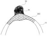
이러한 경우에, 도 1에 도시된 것과 같은 기존의 스텐트(100)를 사용하여 코일 색전술을 시술하면, 시술 후에 뇌동맥류 내부로 충전된 코일이 뇌동맥으로 유출되는 문제가 발생하곤 한다. 도 2a 내지 도 2c는 종래의 스텐트(100)를 사용하여 뇌동맥류에 대한 코일 색전술 시술을 할 경우에, 코일 유출 문제가 발생할 수 있는 뇌동맥류의 형상을 예시적으로 보여 주는 도면이다. 도 2a는 모동맥(parent artery, 10)에 발생한 뇌동맥류(20)가 상대적으로 넓은 입구(neck)를 갖는 광경 뇌동맥류(wide neck cerebral aneurysm)인 경우이고, 도 2b는 좌우 모동맥(10)으로 분기되는 기저동맥(12)의 말단(basilar artery top)에 뇌동맥류(22)가 발생한 경우이며, 도 2c는 모동맥(10)과 분지 혈관(14)이 만나는 지점에서 뇌동맥류(24)가 발생한 경우이다. 도 2a 내지 2c에 도시된 것과 같은 뇌동맥류(20, 22, 24)는 뇌동맥류 자체가 특이한 형상을 가지거나 및/또는 그 위치 등으로 인하여, 종래와 같은 스텐트(100, 도 1 참조)를 사용할 경우에 뇌동맥류(20, 22, 24)의 입구와 스텐트(100) 사이에는 상당히 큰 틈이 존재할 수 있다. 이 경우에, 뇌동맥류(20, 22, 24)에 충전된 코일이 혈관으로 다시 빠져 나올 가능성이 상당히 높으며, 유출된 코일에 의하여 혈관(10, 12, 14)에 손상이 발생하거나 또는 코일이 혈관(10, 12, 14)의 일부, 심한 경우에는 혈관 전체를 막는 부작용을 일으킬 수 있다.In such a case, when the coil embolization is performed using the
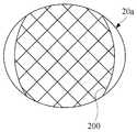
도 3a 및 도 3b는 광경 뇌동맥류에 종래의 코일 색전술용 스텐트(100)를 설치한 모습을 도식적으로 보여 주는 도면으로서, 도 3a는 뇌동맥류(20)의 입구(20a)에서 바라본 모습이고, 도 3b는 스텐트(100)가 뇌동맥에 설치된 전체적인 형상을 보여 주는 도면이다. 도 3a 및 도 3b를 참조하면, 종래의 스텐트(100)는 그 직경이 광경 뇌동맥류(20)의 입구(20a)의 직경보다 상당히 작기 때문에, 스텐트(100)와 뇌동맥류의 입구(20a) 사이에 상당히 큰 틈이 존재하며, 이 틈을 통해서 코일(30)이 뇌혈관(10)으로 빠져나올 가능성이 상당히 높다는 것을 알 수 있다.
3A and 3B are diagrams showing a state in which a conventional stent for
본 발명에서 해결하고자 하는 하나의 과제는 넓은 입구를 가지는 광경 뇌동맥류, 기저동맥 말단과 같이 혈관의 굴곡이 심한 영역에 발생한 뇌동맥류, 또는 뇌동맥과 분지 혈관이 만나는 지점 등과 같이 구조가 복잡한 영역에서 발생한 뇌동맥류 등과 같이, 뇌동맥류의 형상이 특이하거나 및/또는 혈관의 형상이나 구조가 복잡한 뇌동맥에 발생한 뇌동맥류에 대한 코일 색전술에 효과적으로 사용될 수 있는 코일 색전술용 스텐트를 제공하는 것이다.
One of the problems to be solved by the present invention is to provide a method of treating a cerebral aneurysm in a complicated area such as a cerebral aneurysm having a wide entrance, a cerebral aneurysm occurring in a region where a blood vessel is severely bent, such as a basal artery end, It is an object of the present invention to provide a stent for coil embolization which can be effectively used for coil embolization of a cerebral aneurysm which is unique in the shape of a cerebral aneurysm and / or has a complex shape and / or structure of a blood vessel, such as a cerebral aneurysm.
상기한 과제를 해결하기 위한 본 발명의 일 실시예에 따른 스텐트는 뇌동맥류의 코일 색전술을 위한 스텐트로서, 외면의 그물 눈을 통해 코일이 상기 뇌동맥류의 내부로 충전될 수 있도록 그물 구조의 금속 세선으로 이루어진 원통형 형상이고, 상기 원통형 형상은 중앙부의 최대 직경이 양쪽 단부 각각의 최대 직경보다 더 크다.According to an aspect of the present invention, there is provided a stent for coagulating aneurysm of the cerebral aneurysm, the stent comprising: And the cylindrical shape has a maximum diameter of the central portion larger than a maximum diameter of each of the both ends.
상기 실시예의 일 측면에 의하면, 상기 원통형 형상은 상기 중앙부가 전체적으로 상기 양쪽 단부보다 튀어 나온 방추형(fusiform) 형상일 수 있다. 또는, 상기 원통형 형상은 상기 중앙부의 일측이 상기 양쪽 단부보다 튀어 나온 반방추형(semi-fusiform) 형상일 수 있다. 후자의 경우에, 상기 스텐트는 상기 중앙부의 튀어 나오지 않은 타측으로 굽은 형상일 수 있다.According to one aspect of the embodiment, the cylindrical shape may be a fusiform shape in which the central portion protrudes from the both ends as a whole. Alternatively, the cylindrical shape may be a semi-fusiform shape in which one side of the central part protrudes from both ends. In the latter case, the stent may be curved to the other side not protruding from the center portion.
상기 실시예의 다른 측면에 의하면, 상기 중앙부에는 방사선 불투과성(radio-opacity) 물질로 형성된 하나 또는 그 이상의 돌출부 마커(protrusion marker)가 설치되어 있을 수 있다.According to another aspect of the embodiment, one or more protrusion markers formed of a radio-opacity material may be provided at the center portion.
상기 실시예의 또 다른 측면에 의하면, 상기 중앙부는 4~40mm의 길이를 가질 수 있다. 그리고 상기 중앙부의 최대 직경은 2~8mm의 크기를 가질 수 있다.According to another aspect of the embodiment, the central portion may have a length of 4 to 40 mm. The maximum diameter of the center portion may be 2 to 8 mm.
상기 실시예의 또 다른 측면에 의하면, 상기 스텐트는 양쪽 단부 각각에서 끝으로 갈수록 직경이 증가하는 나팔관 형상을 가질 수 있다.According to another aspect of the embodiment, the stent may have a trumpet shape in which the diameter increases from each end to the end.
상기 실시예의 또 다른 측면에 의하면, 상기 스텐트는 상기 양쪽 단부 각각의 그물 눈의 크기가 상기 중앙부의 그물 눈의 크기보다 더 작을 수 있다.
According to another aspect of the embodiment, the size of the mesh of each of the ends of the stent may be smaller than the size of the mesh of the central portion.
본 발명에 실시예에 따른 뇌동맥류의 코일 색전술에 사용되는 스텐트는 대체적으로 중앙부가 양쪽 단부보다 튀어 나온 볼록한 형상을 갖는다. 이러한 형상의 스텐트는 입구가 상대적으로 큰 와이드 넥 뇌동맥류(wide neck cerebral aneurysm)는 물론 굴곡이 심한 뇌혈관의 영역에 발생한 뇌동맥류 또는 뇌동맥과 다른 혈관이 만나는 지점과 같이 구조가 복잡한 영역에 발생한 뇌동맥류에 적용되더라도, 뇌동맥류의 입구와 스텐트의 사이에 생기는 공간을 최소화할 수 있다. 이에 따라서, 뇌동맥류의 코일 색전술 시술에 있어서, 뇌동맥류의 내부에 충전된 코일이 뇌동맥으로 다시 빠져 나오는 것을 막거나 또는 최소화할 수 있으므로, 뇌동맥류로부터 충전된 코일이 혈관으로 빠져 나와서 생기는 부작용을 예방할 수 있다. 뿐만 아니라, 스텐트는 중앙부에 하나 또는 그 이상의 돌출부 마커가 구비되어 있어서, 시술시에 스텐트의 중앙부가 뇌동맥류의 입구에 정확하게 배치되도록 할 수 있다.
The stent used in the coil embolization of the cerebral aneurysm according to the embodiment of the present invention generally has a convex shape protruding from both ends of the central portion. This type of stent has a wide neck cerebral aneurysm with a relatively large entrance, as well as a cerebral aneurysm in the area of severe cerebral vasculature, or a cerebral aneurysm in the complex area of the cerebral artery, It is possible to minimize the space between the entrance of the cerebral aneurysm and the stent. Therefore, in coil embolization of the aneurysm of the cerebral artery, it is possible to prevent or minimize the coil that is filled in the aneurysm of the cerebral artery from coming back to the cerebral artery, thereby preventing the side effect caused by the coil that is filled from the cerebral aneurysm into the blood vessel. . In addition, the stent is provided with one or more protruding markers at the center, so that the central portion of the stent can be accurately positioned at the entrance of the aneurysm of the cerebral artery during the procedure.
도 1은 뇌동맥류의 코일 색전술에 사용되는 종래의 스텐트를 보여 주는 정면도와 측면도이다.
도 2a 내지 도 2c는 각각 도 1의 스텐트를 사용할 경우에 문제점이 발생할 수 있는 뇌동맥류의 형상을 도식적으로 보여 주는 것으로서, 도 2a는 상대적으로 넓은 입구(neck)를 갖는 광경 뇌동맥류(wide neck cerebral aneurysm)인 경우이고, 도 2b는 기저동맥의 말단(basilar artery top)에 뇌동맥류가 발생한 경우이며, 도 2c는 모동맥과 분지 혈관이 만나는 지점에서 뇌동맥류가 발생한 경우이다.
도 3a 및 도 3b는 광경 뇌동맥류가 발생한 뇌동맥에 도 1의 스텐트를 설치한 경우를 도식적으로 보여 주는 도면으로서, 도 3a는 뇌동맥류의 입구에서 바라본 도면이고, 도 3b는 단면도이다.
도 4는 본 발명에 일 실시예에 따른 뇌동맥류의 코일 색전술을 위한 스텐트를 보여 주는 정면도이다.
도 5는 도 4의 스텐트가 광경 뇌동맥류가 발생한 뇌동맥에 삽입되어 설치된 모습을 도식적으로 보여 주는 도면이다.
도 6a 및 도 6b는 광경 뇌동맥류가 발생한 뇌동맥에 도 4의 스텐트를 설치한 모습을 도식적으로 보여 주는 도면으로서, 도 6a는 뇌동맥류의 입구에서 바라본 모습이고, 도 6b는 전체적인 형상을 보여 주는 단면도이다.
도 7은 본 발명에 다른 실시예에 따른 뇌동맥류의 코일 색전술을 위한 스텐트의 형상을 보여 주는 정면도이다.
도 8은 도 7의 스텐트가 뇌동맥과 분지 혈관이 만나는 지점에서 발생한 뇌동맥류에 대한 코일 색전술을 위하여 설치된 모습을 보여 주는 도면이다.
도 9는 본 발명에 또 다른 실시예에 따른 뇌동맥류의 코일 색전술을 위한 스텐트의 형상을 보여 주는 정면도이다.
도 10은 도 9의 스텐트가 기저 동맥이 양쪽 뇌동맥으로 분기되는 지점에서 발생한 뇌동맥류에 대한 코일 색전술을 위하여 설치된 모습을 보여 주는 도면이다.
도 11은 본 발명에 또 다른 실시예에 따른 뇌동맥류의 코일 색전술을 위한 스텐트의 형상을 보여 주는 정면도이다.1 is a front view and a side view showing a conventional stent used for coil embolization of a cerebral aneurysm.
FIGS. 2A to 2C are diagrams illustrating a shape of a cerebral aneurysm which may cause a problem when the stent of FIG. 1 is used. FIG. 2A shows a wide neck cerebral artery having a relatively wide neck, aneurysm), FIG. 2B shows a case where an aneurysm of the cerebral artery occurs at the basilar artery top, and FIG. 2C shows a case where an aneurysm of the cerebral artery occurs at the point where the artery meets the branch vessel.
FIGS. 3A and 3B are diagrams showing a case where the stent of FIG. 1 is installed in a cerebral artery in which an optic cerebral aneurysm is generated. FIG. 3A is a view from the entrance of a cerebral aneurysm, and FIG.
4 is a front view showing a stent for coil embolization of a cerebral aneurysm according to an embodiment of the present invention.
FIG. 5 is a diagram schematically showing a state in which the stent of FIG. 4 is inserted into a cerebral artery in which an optic cerebral aneurysm develops.
FIGS. 6A and 6B are diagrams showing a state in which a stent shown in FIG. 4 is installed in a cerebral artery in which an optic cerebral aneurysm develops. FIG. 6A is a view viewed from an entrance of a cerebral aneurysm. to be.
7 is a front view showing the shape of a stent for coil embolization of a cerebral aneurysm according to another embodiment of the present invention.
FIG. 8 is a view showing a state in which the stent of FIG. 7 is installed for coil embolization of a cerebral aneurysm occurring at a point where a cerebral artery meets a branch vessel.
FIG. 9 is a front view showing a shape of a stent for coil embolization of a cerebral aneurysm according to another embodiment of the present invention. FIG.
FIG. 10 is a view showing a state in which the stent of FIG. 9 is installed for coil embolization of a cerebral aneurysm occurring at a point where a base artery branches into both cerebral arteries.
11 is a front view showing a shape of a stent for coil embolization of a cerebral aneurysm according to yet another embodiment of the present invention.
이하, 첨부된 도면들을 참조하여 본 발명의 실시예를 상세하게 설명한다. 본 명세서에서 사용되는 용어는 실시예에서의 기능 및 효과를 고려하여 선택된 용어들로서, 그 용어의 의미는 사용자 또는 운용자의 의도 또는 업계의 관례 등에 따라 달라질 수 있다. 따라서 후술하는 실시예들에서 사용된 용어의 의미는, 본 명세서에 구체적으로 명시된 경우에는 명시된 정의에 따르며, 구체적으로 명시하지 않는 경우, 당업자들이 일반적으로 인식하는 의미로 해석되어야 할 것이다.
Hereinafter, embodiments of the present invention will be described in detail with reference to the accompanying drawings. The terms used in the present specification are terms selected in consideration of the functions and effects in the embodiments, and the meaning of the terms may vary depending on the intention of the user or the operator or industry custom. Therefore, the meaning of the term used in the following embodiments is based on the defined definition when specifically stated in this specification, and unless otherwise stated, it should be interpreted in a sense generally recognized by those skilled in the art.
도 4는 본 발명에 일 실시예에 따른 뇌동맥류의 코일 색전술을 위한 스텐트를 보여 주는 정면도이다.4 is a front view showing a stent for coil embolization of a cerebral aneurysm according to an embodiment of the present invention.
도 4를 참조하면, 스텐트(200)는 전체적으로 그물 구조의 금속 세선(202)으로 이루어져 있는 원통형 형상이다. 스텐트(200)는 금속 세선(202)으로 이루어진 그물 구조에 의하여 원통형 형상의 외면이 한정되지만 양쪽 단부의 외면은 모두 개방되어 있다. 스텐트(200)의 외면에는 다수의 빈 공간(204, '그물 눈'에 대응함)이 존재한다. 이러한 빈 공간(204)은 코일 색전술 시술 시에 코일이 스텐트(200)의 내부로부터 뇌동맥류로 삽입되는 통로로서 기능한다.Referring to FIG. 4, the
스텐트(200)는 중앙부(middle portion, 200a)와 이 중앙부(200a)의 양쪽 방향으로 위치한 한 쌍의 단부(edge portion, 200b, 200c)로 구분할 수 있다. 이러한 중앙부(200a)와 단부(200b, 200c)의 구분은 물리적인 것이거나 또는 관념적 및/또는 기능적인 구분일 수도 있다. 예를 들어, 도면에 도시되어 있지는 않지만 중앙부(200a)와 단부(200b, 200c)의 구분을 위하여 보조 부재가 스텐트(200), 즉 중앙부(200a)와 단부(200b, 200c)의 경계에 추가로 구비되어 있을 수 있다. 또는, 스텐트(200)가 전체적으로 원기둥 형상에서 가운데 부분에서만 튀어 나온 형상인 경우에, 중앙부(200a)는 스텐트(200)의 중심부를 포함하면서 튀어 나온 부분이고, 단부(200b, 200c)는 중앙부(200a)의 양쪽 가장자리 부분일 수 있다. 이와는 달리, 뇌동맥류가 발생한 뇌동맥의 내부로 스텐트(200)가 삽입되어 설치된 경우에, 적어도 뇌동맥류의 입구를 커버하는 크기를 가지는 스텐트(200)의 중심 부분이 스텐트(200)의 중앙부(200a)이고, 그 이외의 부분이 단부(200b, 200c)가 될 수도 있다.The
그리고 실시예에 따라서는 단부(200b, 200c)는 중앙부(200a)와 인접하는 제1 단부(200b)와 이 제1 단부(200b)의 외측, 즉 중앙부(200a)의 반대쪽으로 인접하는 제2 단부(200c)로 구분할 수 있다. 예컨대, 도 4에 도시된 바와 같이, 스텐트(200)의 단부(200b, 200c)가 내측 부분(중앙부(200a)에 인접한 부분)보다 외측 부분의 직경이 더 큰 나팔관 형상을 가질 경우에, 내측 부분이 제1 단부(200b)에 해당되고, 외측 부분이 제2 단부(200c)에 해당될 수 있다. 이와 같이, 단부(200b, 200c)의 제1 단부(200b) 및 제2 단부(200c)로의 구분은 물리적인 것일 수 있으나, 여기에만 한정되는 것은 아니다. 후술하는 바와 같이, 스텐트(200)는 나팔관 형상이 아니고 단부(200b, 200c)의 직경이 전체적으로 동일할 수 있는데, 이 경우에는 제1 단부(200b)와 제2 단부(200c)는 물리적으로 구분이 되지 않을 수도 있다.The
이러한 스텐트(200)는 적어도 중앙부(200a)의 최대 직경(D1)이 제1 단부(200b)의 최대 직경(D2)보다 더 큰 특징을 갖는다. 여기서, 최대 직경(D1, D2)이란 문자 그대로 해당 부분에서 값이 제일 큰 직경을 가리킨다. 예를 들어, 스텐트(200)는 전체적으로 중앙부(200a)가 제1 단부(200b) 보다 튀어 나온 방추형(fusiform) 형상을 가짐으로써, 중앙부(200a)의 최대 직경(D1)이 제1 단부(200b)의 최대 직경보다 더 클 수 있다.The
또한, 스텐트(200)가 전체적으로 나팔관 형상을 갖는 경우에, 중앙부(200a)의 최대 직경(D1)은 제2 단부(200c)의 최대 직경(D3)보다 더 클 수도 있다. 하지만, 본 실시예가 여기에만 한정되는 것은 아니며, 중앙부(200a)의 최대 직경(D1)은 제2 단부(200c)의 최대 직경(D3)과 크기가 같거나 또는 더 작을 수도 있다.The maximum diameter D1 of the
본 실시예의 다른 측면에 의하면, 스텐트(200)는 여러 가지 형상의 프로파일을 가짐으로써, 중앙부(200a)의 최대 직경(D1)이 제1 단부(200b)의 최대 직경(D2)보다 더 클 수 있다. 즉, 스텐트(200)는 전술한 조건(D1>D2)을 만족하면서 실질적으로 다양한 프로파일을 갖도록 구현될 수 있다. 예컨대, 스텐트(200)는 직경이 제2 단부(200c)의 끝 부분으로부터 제1 단부(200b)를 거쳐서 중앙부(200a)의 중심으로 가면서 점진적으로 증가하는 윤곽을 가질 수 있다. 또는, 스텐트(200)는 제1 및 제2 단부(200b, 200c)의 직경은 일정하지만 중앙부(200a)에서는 중심으로 갈수록 직경이 점진적으로 증가하는 프로파일을 가질 수도 있다. 이 때, 중앙부(200a)는 중심으로 갈수록 점진적으로 직경이 증가하여 중심에서 최대 직경을 갖거나 또는 최대 직경을 갖는 부분이 일정한 폭(즉, 최대로 돌출되어 나온 중앙부(200a)의 중심 부분이 평평한 프로파일)을 가질 수도 있다.According to another aspect of the present embodiment, the
이와 같이, 적어도 제1 단부(200b)보다 중앙부(200a)가 더 돌출된 프로파일을 갖는 스텐트(200)는 뇌동맥류가 발생한 뇌혈관에 삽입되어 설치된 경우에, 뇌동맥류의 입구와 스텐트(200)의 사이에 생기는 틈을 없애거나 최소화함으로써, 뇌동맥류에 충전된 코일이 이탈되는 것을 방지 또는 최소화할 수 있다. 특히, 광경 뇌동맥류(도 2a 참조)나 또는 혈관의 형상이나 구조가 특이한 뇌동맥의 부분에 발생한 뇌동맥류(도 2b 및 도 2c 참조)의 경우에, 본 발명의 실시예와 같은 형상의 스텐트(200)는 코일의 이탈 방지에 보다 효과적일 수 있다.The
전술한 바와 같이, 스텐트(200)의 형상은 금속 세선(202)으로 형성된 그물 모양에 의하여 한정될 수 있다. 즉, 스텐트(200)는 금속 세선(202)이 격자 구조로 엮여서 방추형 형상을 가질 수 있다. 격자에 의하여 한정되는 빈 공간(204, 그물 눈)의 형태는 마름모일 수 있지만, 이에 한정되는 것은 아니다. 빈 공간(204)은 코일의 삽입 시술에 필요한 넓이 이상의 넓이를 갖는다면 그 형상에 특별한 제한이 없다. 예를 들어, 빈 공간(204)은 코일의 삽입 시술에 사용되는 미세 카테터가 통과할 수 있는 넓이, 예컨대 1mm 미만의 외경을 갖는 미세 카테터가 쉽게 통과할 수 있는 넓이(예컨대, 1mm2 이상)를 가질 수 있다. 이러한 격자를 형성하는 금속 세선(202)은 이웃하는 격자의 모서리가 서로 연결된 닫힌(closed) 형태(도 4 참조)이거나 또는 이웃하는 일부 격자의 모서리가 연결되어 있지 않은 열린(open) 형태일 수 있다.As described above, the shape of the
이와 같이, 본 발명의 실시예에 따른 카테트(200)는 제1 단부(200b)가 중앙부(200a)의 양쪽으로 위치하며 그 최대 직경(D2)이 중앙부(200a)의 최대 직경(D1)보다 작다. 이러한 조건을 만족하면서, 제1 및 제2 단부(200b, 200c)는 전체적으로 직경이 동일하거나 또는 외측으로 갈수록 직경이 작아지는 프로파일을 가질 수 있다. 또는, 도 4에 도시된 바와 같이, 단부(200b, 200c)는 제2 단부(200c)의 직경이 바깥쪽으로 갈수록 증가하는 나팔관 형상을 가질 수도 있다. 이러한 나팔관 형상의 스텐트(200)는 혈관 내부로 삽입되었을 때 제2 단부(200c)에서 혈관의 내벽에 접촉되도록 함으로써, 스텐트(200)가 뇌동맥 내부의 원하는 위치에 보다 잘 고정되도록 할 수 있다.As described above, the
스텐트(200)는 양쪽 단부(200b, 200c), 보다 구체적으로 제2 단부(200c) 각각의 최외각 부분에 설치되어 있는 단부 마커(end marker, 212)를 포함할 수 있다. 각 단부 마커(212)는 하나 또는 그 이상이 될 수 있는데, 통상적으로 방사선 불투광성 물질로 형성된다. 스텐트(200)의 양쪽 제2 단부(200c)에 각각 구비되어 있는 단부 마커(212)는, 시술자가 X선 투시 하에서 혈관 내부로 삽입되는 스텐트(200)의 양쪽 끝부분, 즉 원위부와 근위부의 위치를 용이하게 확인할 수 있도록 한다.The
본 실시예의 일 측면에 의하면, 스텐트(200)는 단부 마커(212) 외에 중앙부(200a)에 돌출부 마커(protrusion marker, 214)를 더 포함할 수 있다. 돌출부 마커(214)는 하나 또는 그 이상이 될 수 있는데, 도 4에는 돌출부 마커(214)가 하나인 경우가 도시되어 있다. 돌출부 마커(214)는 스텐트(200)의 중앙부(200a), 특히 중앙부(200a)에서 최대 직경을 갖는 부분의 위치를 시술자에게 알려주기 위한 것이다. 따라서, 돌출부 마커(214)는, 도 4에 도시된 것과 같이, 최대 직경(D1)을 갖는 부분에 하나만 설치되거나 또는 복수 개, 예컨대 돌출부 마커(214)를 기준으로 좌우 대칭으로 2개가 더 추가되어 총 3개가 설치됨으로써, 시술자는 중앙부(200a)에서 특히 돌출된 부분의 위치를 보다 용이하게 파악할 수 있다. 이러한 돌출부 마커(214)는 해당 부분(돌출된 부분)이 뇌동맥류의 입구에 정확하게 위치하도록 시술하는데 이용되기 때문에, 광경 뇌동맥류나 혈관의 구조나 형상이 특이한 부분에 발생한 뇌동맥류의 시술에 보다 유용하게 활용될 수 있다.According to one aspect of the present embodiment, the
그리고, 본 실시예의 일 측면에 의하면, 중앙부(200a)의 최대 직경(D1)은 2.5mm 이상에서 8mm 이하가 될 수 있다. 그리고 중앙부(200a)의 길이(L1)는 4mm 이상 에서 30mm 이하가 될 수 있다. 이러한 중앙부(200a)의 최대 직경(D1) 및 길이(L1)에 따라 중앙부(200a)의 방추형 형상은 좌우 대칭이면서 완만한 경사 또는 급격한 경사를 가질 수 있다. 그리고 스텐트(200)의 제1 및 제2 단부(200b, 200c)의 직경(L2+L3)은 뇌동맥류가 발생한 뇌동맥의 내경을 고려하여, 2mm 이상 내지 6mm 이하일 수 있다. 그리고 스텐트(200)의 전체 길이(L1+2ㅧ(L2+L3))는 중앙부(200a)와 양쪽 단부(200b, 200c)의 길이의 합으로 약 10mm 이상에서 40mm 이하가 될 수 있다.According to an aspect of this embodiment, the maximum diameter D1 of the
전술한 바와 같은 형상을 갖는 본 발명의 일 실시예에 따른 스텐트(200)의 금속 세선(202)은 형상 기억 합금으로 형성될 수 있다. 형상 기억 합금으로는 통상적으로 니티놀(nitinol)이 사용되나, 여기에만 한정되는 것은 아니다. 니티놀은 니켈과 티탄을 섞어 만든 합금이다. 형상 기억 합금은 온도가 변함에 따라 결정 구조가 변하는 특성이 있으며, 저온에서 어느 모양으로든 변형이 가능하지만 온도가 상승(예컨대, 상온이나 체온)하면 다시 원래 모습대로 복원된다. 그리고 복원 시에는 그 재질의 특성 또한 더 단단하게 변할 수 있다. 이러한 형상 기억 합금의 특징에 따라서 스텐트(200)는 상온에서는 혈관 내부에 삽입시키기 쉽도록 매우 작은 크기를 가지지만, 혈관 내부에 삽입되면 온도 변화에 의해 자가팽창(self-expanding)하여 혈관의 내벽에 안착하게 된다.The
도 5는 도 4의 스텐트(200)가 광경 뇌동맥류(wide neck cerebral aneurysm)가 발생한 뇌혈관(10)에 삽입된 모습을 도식적으로 보여 주는 도면이다. 도 5에서는 도시의 편의를 위하여 스텐트(200)는 단부의 직경이 일정한 것으로 도시되어 있으며, 또한 단부 마커와 돌출부 마커에 대한 도시도 생략하였다. 그리고 도 5의 도면은 코일 색전술을 시술하여 뇌동맥류(20)의 내부에 코일(30)이 가득 충전되어 있는 경우이다.FIG. 5 is a diagram schematically showing a state in which the
도 5를 참조하면, 본 발명의 일 실시예에 따른 뇌동맥류의 코일 색전술을 위한 스텐트(200)는 뇌동맥류(20)가 발생한 뇌동맥(10)의 내부에 삽입된다. 스텐트(200), 특히 스텐트(200)의 중앙부(200a, 도 4 참조)는 적어도 뇌동맥류(20)가 발생한 부분을 커버하도록 뇌동맥(10)의 내부에 위치하게 된다. 뇌동맥(10)에 발생한 뇌동맥류(20)가 광경 뇌동맥류인 경우에, 종래의 스텐트(100, 도 1 참조)로 뇌동맥류(20)의 입구를 효과적으로 막는 것이 쉽지 않으며, 스텐트(100)와 뇌동맥류(20)의 입구 사이에는 상대적으로 큰 틈이 존재한다(도 3a 참조). 반면, 본 발명의 일 실시예에 따른 스텐트(200)를 사용하는 경우, 스텐트(200)는 중앙부(200a, 도 4 참조)가 제1 단부(200b, 도 4 참조)보다 돌출되어 있는 방추형 형상이므로, 중앙부(200a)가 뇌동맥류(20)의 입구에 밀착되어 광경 뇌동맥류(20)라도 그 입구를 효과적으로 차단할 수 있다. 따라서 본 발명의 일 실시예에 따른 스텐트(200)를 사용하면, 코일 색전술에서 뇌동맥류(20)의 내부로 충전된 코일(30)이 뇌동맥류로부터 이탈되는 것을 효과적으로 방지할 수 있다.Referring to FIG. 5, a
도 6a 및 도 6b는 광경 뇌동맥류(20)에 본 발명의 실시예에 따른 스텐트(200)를 설치한 모습을 도식적으로 보여 주는 도면으로서, 도 6a는 뇌동맥류(20)의 입구(20a)에서 바라본 모습이고, 도 6b는 전체적인 형상을 보여 주는 단면도이다. 도 6a 및 도 6b를 참조하면, 본 발명의 실시예에 따른 스텐트(200)는 중앙부의 직경이 단부보다 더 큰 볼록한 형상을 가지므로, 스텐트(200)와 뇌동맥류의 입구(20a) 사이에는 거의 틈이 존재하지 않는다는 것을 알 수 있다. 따라서 스텐트(200)는 광경 뇌동맥류(20)에 충전된 코일(30)이 뇌동맥(10)으로 다시 빠져나올 가능성을 상당히 감소시킬 수 있다는 것을 확인할 수 있다.
6A and 6B are diagrams showing a state in which a
도 7은 본 발명에 다른 실시예에 따른 뇌동맥류의 코일 색전술을 위한 스텐트의 형상을 보여 주는 정면도이다. 이하, 도 4를 참조하여 전술한 스텐트(200)와의 차이점을 중심으로 설명한다. 따라서, 여기에서 구체적으로 설명되지 않은 사항은 도 4를 참조하여 전술한 스텐트(200)에 관한 내용이 동일하게 적용될 수 있다. 다만, 후술하는 실시예에서는 스텐트가 나팔관 모양을 가지는 것이 아니라 단부의 직경이 전체적으로 일정한 프로파일을 갖는 경우에 대해서 설명하는데, 이것이 후술하는 실시예가 나팔관 형상의 스텐트를 배제하는 것은 아니다. 따라서 후술하는 실시예에서 사용된 '단부'라는 용어는 스텐트에서 '중앙부'를 제외한 그 이외의 모든 부분(즉, 도 4의 경우에 제1 및 제2 단부)을 지칭한다.7 is a front view showing the shape of a stent for coil embolization of a cerebral aneurysm according to another embodiment of the present invention. Hereinafter, the difference from the
도 7을 참조하면, 스텐트(300)는, 도 4의 스텐트(200)와 마찬가지로, 중앙부(300a)와 양쪽의 단부(300b)를 갖는다. 그리고 도면을 통해 알 수 있는 바와 같이, 중앙부(300a)의 최대 직경은 단부(300b)의 최대 직경보다 더 크다. 다만, 중앙부(300a)는 전체적으로 돌출된 프로파일을 갖는 것이 아니라 한쪽 방향(도면에서는 우측 방향)으로만 돌출되고 반대쪽(도면에서는 좌측 방향)으로는 단부(300b)와 일직선이 되는 프로파일을 갖는 반방추형(semi-fusiform)의 형상을 갖는다는 점에서, 도 4의 스텐트(200)와 차이가 있다. 그리고 스텐트(300)에는 단부 마커(312)는 물론 돌출부 마커(314)가 구비될 수 있는데, 도 7에 스텐트(300)에 구비된 돌출부 마커(314)는 스텐트(300)의 돌출된 부분의 정확한 위치는 물론 돌출된 방향도 표시하는 기능을 수행할 수 있다.Referring to Fig. 7, the
도 8은 도 7의 스텐트(300)가 뇌동맥류의 코일 색전술을 위하여 사용되는 일례를 보여 주는 것으로서, 뇌동맥과 주변 혈관이 만나는 지점에서 발생한 뇌동맥류에 사용되는 경우이다. 도 8을 참조하면, 뇌동맥(10)과 그 분지 혈관(12)이 만나는 지점에서 발생한 뇌동맥류(24)는 입구가 상대적으로 넓을 수가 있다. 이 경우에, 종래의 일자형 스텐트(100, 도 1 참조)를 사용하여 코일 색전술을 시술하면, 분지 혈관(12)이 뇌동맥(10)에 합류되는 지점의 특이한 형상으로 인하여 스텐트(100)가 뇌동맥류(24)의 입구에 충분히 밀착되지 못할 수가 있다. 반면, 도 4에 도시된 것과 같은 방추형의 스텐트(200)를 사용하면, 뇌동맥류(24)의 입구를 효과적으로 차단할 수 있지만, 뇌동맥류(24)가 발생한 반대쪽의 뇌동맥(10)의 내벽이 스텐트(200)에 의하여 압박될 수가 있다. 이러한 경우, 도 7에 도시된 것과 같은 반방추형의 스텐트(300)를 사용함으로써, 스텐트(300)와 뇌동맥류(24)의 입구 사이의 틈을 줄일 수 있을 뿐만 아니라 뇌동맥류(24)가 발생한 쪽의 반대쪽의 뇌동맥 내벽에 압력이 불필요하게 가해지는 것을 방지할 수 있다.
FIG. 8 shows an example in which the
도 9는 본 발명에 또 다른 실시예에 따른 뇌동맥류의 코일 색전술을 위한 스텐트의 형상을 보여 주는 정면도이다. 이하, 도 4 및 도 7을 참조하여 전술한 스텐트(200, 300)와의 차이점을 중심으로 설명한다. 따라서 여기에서 구체적으로 설명되지 않은 사항은 도 4 및 도 7을 참조하여 전술한 스텐트(200, 300)에 관한 내용이 동일하게 적용될 수 있다.FIG. 9 is a front view showing a shape of a stent for coil embolization of a cerebral aneurysm according to another embodiment of the present invention. FIG. Hereinafter, differences from the
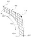
도 9를 참조하면, 스텐트(400)는, 도 4의 스텐트(200) 및 도 7의 스텐트(300)와 마찬가지로, 중앙부(400a)와 양쪽의 단부(400b)를 갖는다. 그리고 도면을 통해 알 수 있는 바와 같이, 중앙부(400a)의 최대 직경은 단부(400b)의 최대 직경보다 더 크다. 그리고 도 7의 스텐트(300)와 마찬가지로, 중앙부(400a)는 전체적으로 돌출된 프로파일을 갖는 것이 아니라 한쪽 방향(도면에서는 오른쪽 방향)으로만 돌출되고 반대쪽(도면에서는 왼쪽 방향)으로는 단부(400b)와 직선이 되는 프로파일을 갖는 반방추형(semi-fusiform)의 형상을 갖는다. 다만, 도 9의 스텐트(400)는 중앙부(400a)에서 소정의 각도, 예컨대 10~90도의 각도로 굽은 프로파일을 갖는다는 점에서, 도 7의 스텐트(300)와 차이가 있다. 스텐트(400)에는 단부 마커(412)는 물론 돌출부 마커(414)가 구비될 수 있는데, 특히 돌출부 마커(414)는 중앙부(400a)에서 돌출된 부분의 위치는 물론 돌출된 방향도 표시하는 기능을 수행할 수 있다는 점에서, 도 7의 스텐트(300)와 동일하다.Referring to Fig. 9, the
도 10은 도 9의 스텐트(400)가 뇌동맥류의 코일 색전술을 위하여 사용되는 일례를 보여 주는 것으로서, 기저 동맥이 양쪽의 뇌동맥으로 분기되는 지점에서 뇌동맥류가 발생한 경우이다. 도 10을 참조하면, 기저 뇌동맥(12)이 양쪽 뇌동맥(10)으로 분기되는 지점에서 발생한 뇌동맥류(22)는 그 입구가 상대적으로 넓을 수가 있다. 이 경우에, 종래의 일자형 스텐트(100, 도 1 참조)는 넓은 뇌동맥류(22)의 입구를 충분히 밀착하지 못할 수가 있다. 그리고 도 4에 도시된 것과 같은 방추형의 스텐트(200)나 도 7에 도시된 것과 같은 반방추형의 스텐트(300)를 사용하더라도 혈관(10, 12)의 복잡한 구조로 인하여 뇌동맥류(22)의 입구를 효과적으로 차단할 수 없을 수가 있다. 반면, 도 9에 도시된 것과 같은 굽은 형상의 반방추형의 스텐트(400)를 사용함으로써, 스텐트(400)와 뇌동맥류(22)의 입구 사이의 틈을 효과적으로 줄일 수 있다.
FIG. 10 shows an example in which the
도 11은 본 발명에 또 다른 실시예에 따른 뇌동맥류의 코일 색전술을 위한 스텐트의 형상을 보여 주는 정면도이다. 이하, 도 4, 도 7, 및 도 9를 참조하여 전술한 스텐트(200, 300, 400)와의 차이점을 중심으로 설명한다. 따라서 여기에서 구체적으로 설명되지 않은 사항은 도 4, 도 7, 및 도 9를 참조하여 전술한 스텐트(200, 300, 400)에 관한 내용이 동일하게 적용될 수 있다.11 is a front view showing a shape of a stent for coil embolization of a cerebral aneurysm according to yet another embodiment of the present invention. Hereinafter, differences from the
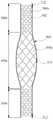
도 11을 참조하면, 스텐트(500)는, 전술한 다른 스텐트(200, 300, 400)와 마찬가지로, 중앙부(500a)와 양쪽의 단부(500b)를 갖는다. 그리고 도면을 통해 알 수 있는 바와 같이, 중앙부(500a)의 최대 직경은 단부(500b)의 최대 직경보다 더 크다. 그리고 도 4의 스텐트(200)와 마찬가지로 중앙부(500a)는 전체적으로 돌출된 방추형(fusiform)의 형상을 갖는다. 스텐트(500)에는 단부 마커(512)는 물론 돌출부 마커(514)가 구비될 수 있는데, 특히 돌출부 마커(514)는 중앙부(500a)에서 돌출된 부분의 위치를 표시하는 기능을 수행한다.11, the
다만, 도 11의 스텐트(500)는 그물 모양으로 엮여 있는 금속 세선(502)에 의하여 한정되는 빈 공간(그물 눈, 504a, 504b)의 크기가 중앙부(500a)와 단부(500b)에서 차이가 있다는 점에서 도 4의 스텐트(200)와 차이가 있다. 보다 구체적으로, 스텐트(500)는 중앙부(500a)보다 단부(500b)에서 금속 세선(502)을 보다 촘촘하게 엮어서, 단부(500b)의 그물 눈(504b)의 크기가 중앙부(500a)의 그물 눈(502)의 크기보다 더 작다. 이러한 형상의 스텐트(500)는 단부(500b)에서 혈관 안에서 펼쳐지는 동안 또는 펼쳐진 이후에 혈관벽에 밀착되어지는 힘이 중앙부(500a)보다 더 강하게 할 수 있으며, 그 결과 스텐트(500)가 혈관 안에서 이동(migration)하는 것을 보다 효율적으로 방지할 수 있다.
However, the
이상 바람직한 실시 예를 들어 본 발명을 상세하게 설명하였으나, 본 발명은 전술한 실시 예에 한정되지 않고, 본 발명의 기술적 사상의 범위 내에서 당 분야에서 통상의 지식을 가진 자에 의하여 여러 가지 변형이 가능하다.
While the present invention has been particularly shown and described with reference to exemplary embodiments thereof, it is to be understood that the invention is not limited to the disclosed exemplary embodiments, but, on the contrary, It is possible.
100, 200, 300, 400, 500 : 스텐트
10 : 뇌동맥(뇌혈관 또는 모동맥)
12 : 기저동맥
14 : 분지 혈관
20, 22, 24 : 뇌동맥류
30 : 코일
202, 502 : 금속 세선
204, 504a, 504b : 그물 눈
212, 312, 412, 512 : 단부 마커
214, 314, 414, 514 : 돌출부 마커100, 200, 300, 400, 500: stent
10: cerebral artery (cerebral artery or coronary artery)
12: basilar artery
14: branch vessel
20, 22, 24: Cerebral aneurysm
30: Coil
202, 502: metal thin wire
204, 504a, 504b: net eyes
212, 312, 412, 512: end markers
214, 314, 414, 514: protruding markers
Claims (9)
Translated fromKorean상기 스텐트의 내부로부터 그물 눈을 통해 코일이 상기 스텐트의 외부로 주입되어 상기 뇌동맥류의 입구를 통해 상기 뇌동맥류 내로 충전될 수 있도록 그물 구조의 금속 세선으로 이루어되, 중앙부의 최대 직경이 상기 중앙부에 인접한 양쪽 단부 각각의 최대 직경보다 더 큰 원통형 형상을 가지며,
상기 중앙부는 상기 뇌동맥류의 내부에 충전된 코일이 상기 뇌동맥류의 입구를 통해 빠져 나오는 것을 방지하는 것을 특징으로 하는 뇌동맥류의 코일 색전술을 위한 스텐트.In a stent for coil embolization of the cerebral aneurysm,
And a metal wire having a mesh structure so that a coil can be injected from the inside of the stent into the outside of the stent through an opening of the stent and filled into the cerebral aneurysm through an inlet of the cerebral aneurysm, Has a cylindrical shape larger than the maximum diameter of each of the adjacent ends,
Wherein the central portion prevents a coil filled in the cerebral aneurysm from escaping through the inlet of the cerebral aneurysm.
상기 원통형 형상은 상기 중앙부의 일측이 상기 양쪽 단부보다 돌출된 반방추형(semi-fusiform) 형상인 것을 특징으로 하는 뇌동맥류의 코일 색전술을 위한 스텐트.The method according to claim 1,
Wherein the cylindrical shape is a semi-fusiform shape in which one side of the central portion protrudes from the both ends.
상기 스텐트는 상기 중앙부의 돌출되지 않은 타측 방향으로 굽은 형상인 것은 특징으로 하는 뇌동맥류의 코일 색전술을 위한 스텐트.The method of claim 3,
Wherein the stent has a curved shape in a direction of the other side of the central portion that is not protruded.
상기 중앙부에는 방사선 불투과성(radio-opacity) 물질로 형성된 하나 또는 그 이상의 돌출부 마커(protrusion marker)가 설치되어 있는 것을 특징으로 하는 뇌동맥류의 코일 색전술을 위한 스텐트.The method according to claim 1,
Wherein the central portion is provided with one or more protrusion markers formed of a radio-opacity material.
상기 스텐트는 양쪽 단부 각각에서 끝으로 갈수록 직경이 증가하는 나팔관 형상을 갖는 것을 특징으로 하는 뇌동맥류의 코일 색전술을 위한 스텐트.The method according to claim 1,
Wherein the stent has a trumpet-like shape in which the diameter increases from each end to the end of the stent.
상기 스텐트는 상기 중앙부의 그물 눈의 크기가 상기 양쪽 단부 각각의 그물 눈의 크기보다 더 큰 것을 특징으로 하는 뇌동맥류의 코일 색전술을 위한 스텐트.
The method according to claim 1,
Wherein the stent has a mesh size of the central portion greater than a mesh size of each of the end portions of the stent.
Priority Applications (1)
| Application Number | Priority Date | Filing Date | Title |
|---|---|---|---|
| KR20120054628AKR101480514B1 (en) | 2011-05-26 | 2012-05-23 | Stent for cerebral aneurysm coil embolization |
Applications Claiming Priority (3)
| Application Number | Priority Date | Filing Date | Title |
|---|---|---|---|
| KR1020110050292 | 2011-05-26 | ||
| KR20110050292 | 2011-05-26 | ||
| KR20120054628AKR101480514B1 (en) | 2011-05-26 | 2012-05-23 | Stent for cerebral aneurysm coil embolization |
Publications (2)
| Publication Number | Publication Date |
|---|---|
| KR20120132368A KR20120132368A (en) | 2012-12-05 |
| KR101480514B1true KR101480514B1 (en) | 2015-01-09 |
Family
ID=47217461
Family Applications (1)
| Application Number | Title | Priority Date | Filing Date |
|---|---|---|---|
| KR20120054628AActiveKR101480514B1 (en) | 2011-05-26 | 2012-05-23 | Stent for cerebral aneurysm coil embolization |
Country Status (4)
| Country | Link |
|---|---|
| US (1) | US20140114343A1 (en) |
| EP (1) | EP2716263B1 (en) |
| KR (1) | KR101480514B1 (en) |
| WO (1) | WO2012161509A1 (en) |
Cited By (2)
| Publication number | Priority date | Publication date | Assignee | Title |
|---|---|---|---|---|
| KR20180133994A (en) | 2017-06-07 | 2018-12-18 | 고려대학교 산학협력단 | Packing material for coil embolization, apparatus and method for manufacturing the same |
| KR20190138421A (en) | 2018-06-05 | 2019-12-13 | 인제대학교 산학협력단 | Horizontally installable stent unit |
Families Citing this family (11)
| Publication number | Priority date | Publication date | Assignee | Title |
|---|---|---|---|---|
| US10716573B2 (en) | 2008-05-01 | 2020-07-21 | Aneuclose | Janjua aneurysm net with a resilient neck-bridging portion for occluding a cerebral aneurysm |
| US10028747B2 (en) | 2008-05-01 | 2018-07-24 | Aneuclose Llc | Coils with a series of proximally-and-distally-connected loops for occluding a cerebral aneurysm |
| US9358140B1 (en) | 2009-11-18 | 2016-06-07 | Aneuclose Llc | Stent with outer member to embolize an aneurysm |
| CN108186074A (en) | 2014-02-27 | 2018-06-22 | 因库麦迪斯有限公司 | For treating the framework microcoils of vascular diseases |
| CN104825203A (en)* | 2015-04-14 | 2015-08-12 | 陈旭东 | Cerebral aneurysm embolization therapeutic device and using method thereof |
| KR101593223B1 (en) | 2015-05-15 | 2016-02-12 | (주)시지바이오 | Hybrid stent |
| CN111031936B (en) | 2017-08-17 | 2023-10-10 | 阿里萨医疗股份有限公司 | flow attenuation device |
| JP2021520255A (en) | 2018-04-04 | 2021-08-19 | インキュメデックス インコーポレイテッド | Embolic device with improved reduced diameter coating |
| CN110420080A (en)* | 2018-04-28 | 2019-11-08 | 微创神通医疗科技(上海)有限公司 | Bracket, intervention medical device and intervention medical system |
| KR102230327B1 (en)* | 2019-04-16 | 2021-03-22 | 주식회사 에스앤지바이오텍 | Cerebral aneurysm stent and manufacturing method thereof |
| KR20220068982A (en)* | 2019-07-11 | 2022-05-26 | 더 클리블랜드 클리닉 파운데이션 | Systems and Methods for Model-Based Stent Design and Deployment |
Citations (4)
| Publication number | Priority date | Publication date | Assignee | Title |
|---|---|---|---|---|
| US20040167605A1 (en)* | 2003-02-26 | 2004-08-26 | Elliott Christopher J. | Endoluminal device having enhanced affixation characteristics |
| US20070100430A1 (en)* | 2004-03-30 | 2007-05-03 | Leon Rudakov | Medical device |
| KR20100045211A (en)* | 2008-10-23 | 2010-05-03 | (주) 태웅메디칼 | A double stent |
| KR20120009329A (en)* | 2010-07-23 | 2012-02-01 | (재)예수병원유지재단 | Stent with combined hat geometry |
Family Cites Families (43)
| Publication number | Priority date | Publication date | Assignee | Title |
|---|---|---|---|---|
| US5464449A (en)* | 1993-07-08 | 1995-11-07 | Thomas J. Fogarty | Internal graft prosthesis and delivery system |
| RU2089131C1 (en)* | 1993-12-28 | 1997-09-10 | Сергей Апполонович Пульнев | Stent-expander |
| US5951599A (en)* | 1997-07-09 | 1999-09-14 | Scimed Life Systems, Inc. | Occlusion system for endovascular treatment of an aneurysm |
| ATE311833T1 (en)* | 1999-02-01 | 2005-12-15 | Univ Texas | WOVEN INTRAVASCULAR DEVICE AND METHOD FOR MAKING |
| US6663607B2 (en)* | 1999-07-12 | 2003-12-16 | Scimed Life Systems, Inc. | Bioactive aneurysm closure device assembly and kit |
| US6309367B1 (en)* | 1999-07-23 | 2001-10-30 | Neurovasx, Inc. | Aneurysm shield |
| US20020007222A1 (en)* | 2000-04-11 | 2002-01-17 | Ashvin Desai | Method and apparatus for supporting a body organ |
| US6730119B1 (en)* | 2000-10-06 | 2004-05-04 | Board Of Regents Of The University Of Texas System | Percutaneous implantation of partially covered stents in aneurysmally dilated arterial segments with subsequent embolization and obliteration of the aneurysm cavity |
| US6565601B2 (en)* | 2000-11-15 | 2003-05-20 | Micro Therapeutics, Inc. | Methods for vascular reconstruction of diseased arteries |
| US20030100945A1 (en)* | 2001-11-23 | 2003-05-29 | Mindguard Ltd. | Implantable intraluminal device and method of using same in treating aneurysms |
| US7572288B2 (en)* | 2001-07-20 | 2009-08-11 | Microvention, Inc. | Aneurysm treatment device and method of use |
| US20040158311A1 (en)* | 2003-02-06 | 2004-08-12 | Berhow Steven W. | Intravascular stent |
| US20040260384A1 (en)* | 2003-06-17 | 2004-12-23 | Medtronic Ave | Superelastic coiled stent |
| DE10335649A1 (en)* | 2003-07-30 | 2005-02-24 | Jotec Gmbh | Braid stent for implantation in a blood vessel |
| US8747453B2 (en)* | 2008-02-18 | 2014-06-10 | Aga Medical Corporation | Stent/stent graft for reinforcement of vascular abnormalities and associated method |
| US8623067B2 (en)* | 2004-05-25 | 2014-01-07 | Covidien Lp | Methods and apparatus for luminal stenting |
| US8617234B2 (en)* | 2004-05-25 | 2013-12-31 | Covidien Lp | Flexible vascular occluding device |
| CA2758946C (en)* | 2004-05-25 | 2014-10-21 | Tyco Healthcare Group Lp | Vascular stenting for aneurysms |
| BE1016067A3 (en)* | 2004-06-03 | 2006-02-07 | Frid Noureddine | Luminal endoprosthesis FOR OBSTRUCTION OF ANEURYSM AND METHOD OF MANUFACTURING SUCH STENT. |
| WO2006044632A2 (en)* | 2004-10-15 | 2006-04-27 | Cordis Neurovascular, Inc. | Remodeling device for aneurysms |
| WO2007051183A1 (en)* | 2005-10-28 | 2007-05-03 | Incept, Llc | Flared stents and apparatus and methods for delivering them |
| CN100362971C (en)* | 2005-11-16 | 2008-01-23 | 程英升 | Cardia stent |
| US20070150041A1 (en)* | 2005-12-22 | 2007-06-28 | Nellix, Inc. | Methods and systems for aneurysm treatment using filling structures |
| WO2007076480A2 (en)* | 2005-12-23 | 2007-07-05 | Levy Elad I | Bifurcated aneurysm treatment arrangement |
| GB0603685D0 (en)* | 2006-02-23 | 2006-04-05 | Angiomed Ag | Vascular prosthesis for aneurysms, set of vascular prostheses, method for manufacturing a vascular prosthesis and method for inserting a vascular prosthesis |
| CA2660851A1 (en)* | 2006-08-17 | 2008-02-21 | Nfocus Neuromedical, Inc. | Isolation devices for the treatment of aneurysms |
| DE102006062360A1 (en)* | 2006-12-22 | 2008-06-26 | Aesculap Ag & Co. Kg | Woven artificial organ for an aortic sinus has a first cylindrical section away from a heart, a second cylindrical section with a wider diameter to form a bulbus and a third cylindrical section near to a heart |
| US8118861B2 (en)* | 2007-03-28 | 2012-02-21 | Boston Scientific Scimed, Inc. | Bifurcation stent and balloon assemblies |
| WO2009076515A1 (en)* | 2007-12-11 | 2009-06-18 | Cornell University | Method and apparatus for sealing an opening in the side wall of a body lumen |
| CA3010828A1 (en)* | 2008-01-17 | 2009-07-23 | Boston Scientific Scimed, Inc. | Stent with anti-migration feature |
| US20090192588A1 (en)* | 2008-01-29 | 2009-07-30 | Taeoong Medical Co., Ltd | Biodegradable double stent |
| US8388674B2 (en)* | 2008-02-25 | 2013-03-05 | Mayo Foundation For Medical Education And Research | Conformable stents and methods for making |
| US8100960B2 (en)* | 2008-03-20 | 2012-01-24 | Medtronic Vascular, Inc. | Bloused stent-graft and fenestration method |
| US8041095B2 (en)* | 2008-06-11 | 2011-10-18 | Siemens Aktiengesellschaft | Method and apparatus for pretreatment planning of endovascular coil placement |
| US9179918B2 (en)* | 2008-07-22 | 2015-11-10 | Covidien Lp | Vascular remodeling device |
| KR20100042478A (en)* | 2008-10-16 | 2010-04-26 | (주) 태웅메디칼 | A making method for the stent and the stent thereof |
| US8470013B2 (en)* | 2008-10-20 | 2013-06-25 | Imds Corporation | Systems and methods for aneurysm treatment and vessel occlusion |
| US20100131051A1 (en)* | 2008-11-24 | 2010-05-27 | Medtronic Vascular, Inc. | Systems and Methods for Treatment of Aneurysms Using Zinc Chelator(s) |
| WO2011031587A1 (en)* | 2009-09-10 | 2011-03-17 | Boston Scientific Scimed, Inc. | Endoprosthesis with filament repositioning or retrieval member and guard structure |
| US20120046730A1 (en)* | 2010-04-14 | 2012-02-23 | Abbott Vascular | Methods of treating a condition of a vessel in a patient |
| US20120253454A1 (en)* | 2011-03-31 | 2012-10-04 | Kieran Costello | Stent designs having enhanced radiopacity |
| CN103547222B (en)* | 2011-05-11 | 2016-02-10 | 柯惠有限合伙公司 | Vascular remodeling device |
| US8771341B2 (en)* | 2011-11-04 | 2014-07-08 | Reverse Medical Corporation | Protuberant aneurysm bridging device and method of use |
- 2012
- 2012-05-23KRKR20120054628Apatent/KR101480514B1/enactiveActive
- 2012-05-23EPEP12789310.5Apatent/EP2716263B1/enactiveActive
- 2012-05-23WOPCT/KR2012/004066patent/WO2012161509A1/enactiveApplication Filing
- 2012-05-23USUS14/122,367patent/US20140114343A1/ennot_activeAbandoned
Patent Citations (4)
| Publication number | Priority date | Publication date | Assignee | Title |
|---|---|---|---|---|
| US20040167605A1 (en)* | 2003-02-26 | 2004-08-26 | Elliott Christopher J. | Endoluminal device having enhanced affixation characteristics |
| US20070100430A1 (en)* | 2004-03-30 | 2007-05-03 | Leon Rudakov | Medical device |
| KR20100045211A (en)* | 2008-10-23 | 2010-05-03 | (주) 태웅메디칼 | A double stent |
| KR20120009329A (en)* | 2010-07-23 | 2012-02-01 | (재)예수병원유지재단 | Stent with combined hat geometry |
Cited By (2)
| Publication number | Priority date | Publication date | Assignee | Title |
|---|---|---|---|---|
| KR20180133994A (en) | 2017-06-07 | 2018-12-18 | 고려대학교 산학협력단 | Packing material for coil embolization, apparatus and method for manufacturing the same |
| KR20190138421A (en) | 2018-06-05 | 2019-12-13 | 인제대학교 산학협력단 | Horizontally installable stent unit |
Also Published As
| Publication number | Publication date |
|---|---|
| EP2716263A1 (en) | 2014-04-09 |
| EP2716263B1 (en) | 2016-12-14 |
| EP2716263A4 (en) | 2014-11-19 |
| US20140114343A1 (en) | 2014-04-24 |
| KR20120132368A (en) | 2012-12-05 |
| WO2012161509A1 (en) | 2012-11-29 |
Similar Documents
| Publication | Publication Date | Title |
|---|---|---|
| KR101480514B1 (en) | Stent for cerebral aneurysm coil embolization | |
| US11564817B2 (en) | Procedures for vascular occlusion | |
| JP6841874B2 (en) | Blocking device | |
| CN111278367B (en) | Occlusion device | |
| JP5619925B2 (en) | Flexible vascular closure device | |
| EP3386402B1 (en) | Occlusion device | |
| CA2829799C (en) | Implant, especially for the occlusion of bifurcation aneurysms | |
| KR101300437B1 (en) | Vascular stenting for aneurysms | |
| CA2652176C (en) | Flexible vascular occluding device | |
| CN101472536A (en) | Flexible vascular occlusion device | |
| EP3668417A1 (en) | Flow attenuation device | |
| KR20130032911A (en) | Vascular stenting for aneurysms | |
| JP6100454B2 (en) | Biological lumen occlusion device | |
| CN113423347A (en) | Vascular occlusion device | |
| KR20160022597A (en) | Stent for cerebral aneurysm | |
| KR20130118668A (en) | Intravascular occlusion device | |
| HK40011380A (en) | Occlusion device | |
| JP2008054901A (en) | Intravascular stiffener | |
| HK1261731A1 (en) | Occlusion device | |
| HK1261731B (en) | Occlusion device |
Legal Events
| Date | Code | Title | Description |
|---|---|---|---|
| A201 | Request for examination | ||
| PA0109 | Patent application | Patent event code:PA01091R01D Comment text:Patent Application Patent event date:20120523 | |
| PA0201 | Request for examination | ||
| PG1501 | Laying open of application | ||
| N231 | Notification of change of applicant | ||
| PN2301 | Change of applicant | Patent event date:20121221 Comment text:Notification of Change of Applicant Patent event code:PN23011R01D | |
| E902 | Notification of reason for refusal | ||
| PE0902 | Notice of grounds for rejection | Comment text:Notification of reason for refusal Patent event date:20130927 Patent event code:PE09021S01D | |
| E902 | Notification of reason for refusal | ||
| PE0902 | Notice of grounds for rejection | Comment text:Notification of reason for refusal Patent event date:20140424 Patent event code:PE09021S01D | |
| E701 | Decision to grant or registration of patent right | ||
| PE0701 | Decision of registration | Patent event code:PE07011S01D Comment text:Decision to Grant Registration Patent event date:20141121 | |
| GRNT | Written decision to grant | ||
| PR0701 | Registration of establishment | Comment text:Registration of Establishment Patent event date:20150102 Patent event code:PR07011E01D | |
| PR1002 | Payment of registration fee | Payment date:20150102 End annual number:3 Start annual number:1 | |
| PG1601 | Publication of registration | ||
| FPAY | Annual fee payment | Payment date:20180103 Year of fee payment:4 | |
| PR1001 | Payment of annual fee | Payment date:20180103 Start annual number:4 End annual number:4 | |
| FPAY | Annual fee payment | Payment date:20190102 Year of fee payment:5 | |
| PR1001 | Payment of annual fee | Payment date:20190102 Start annual number:5 End annual number:5 | |
| FPAY | Annual fee payment | Payment date:20190701 Year of fee payment:6 | |
| PR1001 | Payment of annual fee | Payment date:20190701 Start annual number:6 End annual number:6 | |
| PR1001 | Payment of annual fee | Payment date:20200507 Start annual number:7 End annual number:7 | |
| PR1001 | Payment of annual fee | Payment date:20210503 Start annual number:8 End annual number:8 | |
| PR1001 | Payment of annual fee | Payment date:20220329 Start annual number:9 End annual number:9 | |
| PR1001 | Payment of annual fee | Payment date:20240327 Start annual number:11 End annual number:11 |