KR101477846B1 - Dual differential semi-active actuator fit for interaction tasks and fast motion - Google Patents
Dual differential semi-active actuator fit for interaction tasks and fast motionDownload PDFInfo
- Publication number
- KR101477846B1 KR101477846B1KR1020107023148AKR20107023148AKR101477846B1KR 101477846 B1KR101477846 B1KR 101477846B1KR 1020107023148 AKR1020107023148 AKR 1020107023148AKR 20107023148 AKR20107023148 AKR 20107023148AKR 101477846 B1KR101477846 B1KR 101477846B1
- Authority
- KR
- South Korea
- Prior art keywords
- actuator
- mechanical differential
- mechanical
- port
- differential
- Prior art date
- Legal status (The legal status is an assumption and is not a legal conclusion. Google has not performed a legal analysis and makes no representation as to the accuracy of the status listed.)
- Expired - Fee Related
Links
Images


Classifications
- B—PERFORMING OPERATIONS; TRANSPORTING
- B25—HAND TOOLS; PORTABLE POWER-DRIVEN TOOLS; MANIPULATORS
- B25J—MANIPULATORS; CHAMBERS PROVIDED WITH MANIPULATION DEVICES
- B25J9/00—Programme-controlled manipulators
- B25J9/10—Programme-controlled manipulators characterised by positioning means for manipulator elements
- B25J9/102—Gears specially adapted therefor, e.g. reduction gears
- F—MECHANICAL ENGINEERING; LIGHTING; HEATING; WEAPONS; BLASTING
- F16—ENGINEERING ELEMENTS AND UNITS; GENERAL MEASURES FOR PRODUCING AND MAINTAINING EFFECTIVE FUNCTIONING OF MACHINES OR INSTALLATIONS; THERMAL INSULATION IN GENERAL
- F16D—COUPLINGS FOR TRANSMITTING ROTATION; CLUTCHES; BRAKES
- F16D2121/00—Type of actuator operation force
- F16D2121/18—Electric or magnetic
- F16D2121/28—Electric or magnetic using electrostrictive or magnetostrictive elements, e.g. piezoelectric elements
- F—MECHANICAL ENGINEERING; LIGHTING; HEATING; WEAPONS; BLASTING
- F16—ENGINEERING ELEMENTS AND UNITS; GENERAL MEASURES FOR PRODUCING AND MAINTAINING EFFECTIVE FUNCTIONING OF MACHINES OR INSTALLATIONS; THERMAL INSULATION IN GENERAL
- F16H—GEARING
- F16H3/00—Toothed gearings for conveying rotary motion with variable gear ratio or for reversing rotary motion
- F16H3/44—Toothed gearings for conveying rotary motion with variable gear ratio or for reversing rotary motion using gears having orbital motion
- F16H3/72—Toothed gearings for conveying rotary motion with variable gear ratio or for reversing rotary motion using gears having orbital motion with a secondary drive, e.g. regulating motor, in order to vary speed continuously
- F16H3/721—Toothed gearings for conveying rotary motion with variable gear ratio or for reversing rotary motion using gears having orbital motion with a secondary drive, e.g. regulating motor, in order to vary speed continuously the secondary drive being an energy dissipating device, e.g. regulating brake, in order to vary speed continuously
Landscapes
- Engineering & Computer Science (AREA)
- Robotics (AREA)
- Mechanical Engineering (AREA)
- Retarders (AREA)
- Transmission Devices (AREA)
Abstract
Translated fromKoreanDescription
Translated fromKorean본 출원은 2008년 3월 27일에 출원된 미국 임시 특허출원 No. 61/064,813의 이익을 청구하며, 이 미국 임시 특허출원 No. 61/064,813은 참조사항으로 본 명세서에서 통합된다.This application is a continuation-in-part of U.S. Provisional Patent Application No. 61 / 064,813, which is hereby incorporated by reference in its entirety. 61 / 064,813, incorporated herein by reference.
본 발명은 상호작용 작업과 신속한 움직임을 위한 반-능동형 이중 차동 액추에이터에 관한 것이다. 더욱 상세하게는, 본 발명은 로봇의 상호작용 작업, 힘 제어 작업 또는 신속한 움직임 작업을 위해 적합한 이중 차동 반-능동형 액추에이터에 관한 것이다.
The present invention relates to a semi-active dual differential actuator for interactive operation and rapid movement. More particularly, the present invention relates to a dual differential, semi-active actuator suitable for robot interaction, force control or rapid motion operation.
대부분의 현대 로봇 시스템은 신속하며 반복가능한 위치 제어 기계들이다. 그러나, 고비용 R&D 노력에도 불과하고, 대부분 이 시스템들은 시스템들이 미리 프로그램화된 특정 동작을 실행하는 제어 영역에 한정된다. 게다가, 여전히 이 시스템들은 그린딩(grinding), 폴리싱(polishing), 표면 후작업 및 복잡한 조립과 같은 작업 면에서 제한된 성능을 나타낸다. 또한, 경제적으로 이익이 되는 다수의 사람-기계 간의 상호작용 적용예가 확인되었지만(물리 치료, 운동 보조, 수술 보조, 수동 작업 지시, 스포츠 활동, 정형술(ortheses) 및 보철물 동력화(prostheses motorization), 햅틱(haptic), 상호작용 기계들의 원격조정(teleoperation) 등), 매우 적은 적용예만이 성공적으로 실행되어왔다.Most modern robot systems are fast and repeatable position control machines. However, this is only a costly R & D effort, and most of the systems are limited to the control areas where the systems perform certain operations pre-programmed. In addition, these systems still exhibit limited performance in terms of operations such as grinding, polishing, post-surface finishing and complicated assembly. In addition, although a number of economically beneficial man-machine interaction applications have been identified (physical therapy, athletic assistance, surgical assistance, manual work instructions, sports activities, ortheses and prostheses motorization, haptics haptic, teleoperation of interactive machines, etc.), very few applications have been successfully implemented.
지난 25년 동안, 일부 연구원들은 안전하고 범용적인 상호작용을 할 수 있는 로봇 시스템을 형성하기 위한 하나의 목적을 가진 디자인 패러다임을 인식하며 수정하려고 노력해 왔으며, 이로 인해서 상호작용 제어 이론의 개발을 이끌어왔다. 불행하게도, 힘 피드백이 실행될 때, 주로 높은 출력 임피던스 (관성 및 마찰) 때문에 그리고 감지 변환기와 실행 변환기가 통상적으로 함께 배치되지 못하기(non-collocation) 때문에, 종래의 액추에어터는 액추에이터의 사용을 위해 부적합하며 안전하고 범용을 위한 상호작용에 부적합하다고 밝혀졌다.Over the last 25 years, some researchers have tried to recognize and modify the design paradigm with a purpose to form robotic systems that can interact safely and universally, leading to the development of interaction control theory . Unfortunately, because of the high output impedance (inertia and friction) and the non-collocation of the sense transducer and the running transducer, when the force feedback is performed, conventional actuator actuators are used for actuator use It was found unsuitable for inadequate, secure, and universal interactions.
다양한 상호작용 작업을 위해 적합한 안전하고 다용도인 액추에이터는 1) 높은 힘 밀도 또는 토크 밀도, 2)충분한 힘 대역폭, 3) 매우 낮은 출력 임피던스 및 4) 고성능의 힘 표시 기능과 같은 4 개 이상의 기본적인 특징을 가져야한다. 그러나, 어떠한 종래 액추에이터도 상기 모든 기본적인 특성을 동시에 제시하지 못한다.
A versatile, safe and versatile actuator for a wide range of interaction tasks, has four or more basic features such as 1) high power density or torque density, 2) sufficient power bandwidth, 3) very low output impedance, and 4) Should have. However, any conventional actuator does not simultaneously present all of the above basic characteristics.
본 발명에 따르면, 기계적 부하와 상호작용하기 위한 기계식 차동 액추에이터가 제공되며, 이 기계식 차동 액추에이터는 제 1 반-능동형 서브-액추에이터, 제 2 반-능동형 서브-액추에이터, 속도원, 상기 속도원에 결합된 제 1 상호작용 포트, 제 2 상호작용 포트 및 제 1 반-능동형 서브-액추에이터에 결합된 제 3 상호작용 포트를 포함한 3 개의 상호작용 포트를 가지는 제 1 기계식 차동장치 및 상기 속도원에 결합된 제 1 상호작용 포트, 제 2 상호작용 포트 및 제 2 반-능동형 서브-액추에이터에 결합된 제 3 상호작용 포트를 포함한 3 개의 상호작용 포트들을 가지는 제 2 기계식 차동장치를 구비하며, 상기 제 1 기계식 차동장치의 제 2 상호작용 포트와 제 2 기계식 차동장치의 제 2 상호작용 포트는, 부하에 결합하기 위해 형성된 출력부를 형성하도록 함께 결합된다.According to the invention, there is provided a mechanical differential actuator for interacting with a mechanical load, the mechanical differential actuator comprising a first half-active sub-actuator, a second half-active sub-actuator, a velocity circle, A first mechanical differential having three interaction ports including a first interaction port, a second interaction port and a third interaction port coupled to the first half-active sub-actuator, A second mechanical differential having three interaction ports including a first interaction port, a second interaction port and a third interaction port coupled to a second semi-active sub-actuator, The second interaction port of the differential and the second interaction port of the second mechanical differential are connected together to form an output formed to engage the load. It is.
상기 목적과 그 외 다른 목적, 본 발명의 장점 및 특징이 첨부 도면을 참조하여, 단지 예로써 제시된, 본 발명의 비제한적인 설명적 실시예를 열람함으로써 더욱 명백해질 것이다.The foregoing and other objects, advantages and features of the present invention will become more apparent upon a reading of the following non-limiting illustrative embodiment of the invention, given by way of example only, with reference to the accompanying drawings,
이제부터 본 발명에 따른 액추에이터의 비제한적으로 설명된 실시예가 기술된다.A non-limiting illustrative embodiment of an actuator according to the present invention will now be described.
일반적으로, 비제한적으로 설명된 본 발명의 실시예에 따른 액추에이터는 새로운 유형의 작동 장치(actuation mechanism)에 관한 것이며, 이 작동 장치는 두 개의 기계식 차동 장치(differential)를 이용한 출력에 연결되며 입력 속도원(input velocity source)에 연결된 두 개의 반-능동형 액추에이터를 이용한다. 액추에이터의 출력 힘(또는 출력 토크)가 반-능동형 액추에이터의 제동력(braking force)들의 조합에 의해 양 방향으로 제어되도록 형상이 형성된다. 이 개념은 1) 높은 힘 밀도 또는 높은 토크 밀도, 2) 큰 대역폭, 3) 매운 낮은 출력 임피던스 및 4) 고성능(high-fidelity)의 힘 표시 기능(force display capability)을 가능하게 한다. 이러한 특성들에 의해 안전하며 다목적의 로봇 상호작용에 추가하여, 정밀한 힘 제어, 신속한 속도 제어가 가능하다.In general, an actuator according to an embodiment of the present invention, which is non-limitingly described, relates to a new type of actuation mechanism, which is connected to an output using two mechanical differentials, Use two semi-active actuators connected to the input velocity source. The shape is formed such that the output force (or output torque) of the actuator is controlled in both directions by the combination of the braking forces of the semi-active actuator. This concept enables high power density or high torque density, 2) large bandwidth, 3) spicy low output impedance, and 4) high-fidelity force display capability. These features make it possible to provide precise force control and rapid speed control in addition to safe, versatile robot interaction.
액추에이터 이론의 소개.Introduction to Actuator Theory.
액추에이터는 제어가능한 방식으로 특정 형태의 에너지(열, 전기, 화학, 수력, 기계적 에너지 등)를 기계적 힘으로 변형하고 또한 이와 반대로 변형하는 장치이다. 본 명세서에서, 특히 비배타적으로 액추에이터는 예를 들면, 다음과 같은 것을 포함하는 몇몇 서브시스템(subsystem)의 집합일 수 있다.Actuators are devices that transform a specific type of energy (thermal, electrical, chemical, hydraulic, mechanical energy, etc.) into mechanical forces and vice versa in a controllable manner. In this specification, particularly non-exclusively, the actuator may be a collection of several subsystems, including, for example:
●제어 전자장치● Control electronics
●전력 전자장치● Power electronics
●에너지 변환기(들)● Energy converter (s)
●상태 센서(들)(state sensor) 및State sensor (s) and
●트랜스미션 장치(들)● The transmission device (s)
n개의 자유도(degree of freedom)를 가진 로봇 시스템(robotic system)은 n 개의 전력 교환(상호작용) 포트(power exchange(interaction) port)들을 통하여 부하(load)에 연결된다. 개별 상호작용 포트의 상태는 일반화된 힘(generalized force)과 일반화된 속도(generalized speed)인 두 개의 변수(variable)에 의해 정의된다. 정해진 포트의 두 개의 상호작용 상태 변수와 독립적으로 제어하는 것은 가능하지 않다. 종래의 제어는 두 개의 변수 중 하나에 집중된다.A robotic system with n degrees of freedom is connected to the load through n power exchange (interaction) ports. The state of an individual interaction port is defined by two variables, a generalized force and a generalized speed. It is not possible to control independently of two interactive state variables of a given port. Conventional control is concentrated on one of two variables.
속도 (또는 위치) 제어를 위해서, 이상적으로 액추에이터는 작용력(force load)이 상호 작용하는 속도원으로써 작용한다. 직면한 임의의 힘에도 불과하고, 액추에이터는 부하로 전달된 속도 분포(speed profile)를 제어하여야한다. 빈번하게, 이상적인 속도원에 근접한 성능에 도달하도록 설계된 실제 액추에이터는 높은 기계적 임피던스(관성, 마찰, 강성(stiffness))를 가진 부품(component)들을 이용하여 실행된다. 이러한 임피던스(impedance)는 힘 방해(force disturbance)를 용이하게 거부한다. 유동 제어 수력 변환기(hydraulic transducer)와 고비율 기어형 전자기(EM) 모터가 좋은 예이다. 또한 고성능 속도 제어가 낮은 출력 임피던스 액추에이터들을 이용해 가능하나, 비교적 더 넓은 힘 대역폭이 효율적으로 방해에 대항하기 위해서 필요하다. 직접-구동식 EM 모터에 대한 속도 제어가 좋은 예이다.For speed (or position) control, ideally, the actuator acts as a velocity source with which the force load interacts. And the actuator must control the speed profile delivered to the load. Frequently, actual actuators designed to reach performance close to an ideal velocity source are implemented using components with high mechanical impedances (inertia, friction, stiffness). This impedance easily rejects force disturbance. A good example is a hydraulic transducer and a high ratio geared electromagnetic (EM) motor. High performance speed control is also possible with low output impedance actuators, but a relatively wider power bandwidth is needed to efficiently combat disturbances. A good example is speed control for direct-drive EM motors.
힘 제어를 위해서, 이상적으로 액추에이터는 속도 부하와 상호 작용하는 힘 공급원(force source)로써 작용한다. 출력 운동(output motion)에도 불과하고, 액추에이터는 부하로 전해진 힘(또는 토크) 분배를 완전히 제어해야만 한다. 이상적인 힘 공급원에 가능한 한 가장 근접한 성능에 도달하도록 설계된 실제 액추에이터는 매우 낮은 기계적 임피던스를 가진 부품들을 이용하여 실행된다. 출력 임피던스가 출력 운동으로 출력 힘에 대한 감도(sensitivity)로써 간주될 수 있어서, 출력 임피던스는 이롭지못하다. 두 번째 문제는, 고성능의 힘 제어가 요구된다면, 힘 생성 현상과 시스템의 출력 사이의 전달(transmission)이 모델링되지 않은 힘 노이즈를 거의 추가하지 않아야한다는 것이다. 대부분의 높은 힘 밀도 액추에이터는 높은 임피던스(관성 및 마찰)를 나타내기 때문에, 그리고 전달에 의해 추가된 모델링하기 곤란한 힘 노이즈가 있기 때문에, 때때로 힘 제어가 문제될 수 있다.For force control, ideally, the actuator acts as a force source that interacts with the velocity load. It is just an output motion, and the actuator must fully control the force (or torque) distribution delivered to the load. Actual actuators designed to reach the closest performance to the ideal source of force are implemented using components with very low mechanical impedances. The output impedance can be regarded as the sensitivity to the output force in the output motion, so the output impedance is not beneficial. The second problem is that, if high-performance force control is required, the transmission between the force generation phenomenon and the output of the system should add little to un-modeled force noise. Sometimes force control can be a problem because most high-force-density actuators exhibit high impedances (inertia and friction), and because of the power noise that is difficult to model, added by transmission.
라이트 물체를 들어올림과 위치시킴, 단순한 부품을 천천히 조립함, 강성 벽체 밀어올림과 같은 큰 부류의 로봇 업무는 낮은 전력 교환으로 실현된다. 이 단순한 업무들을 위해서, 적합한 액추에이터가 이용된다면, 일반적으로 속도 또는 힘의 제어에 기초한 종래의 피드백으로도 충분하다. 그러나, 상당 양의 전력 교환을 이용한 복잡한 로봇 업무(조작, 이동, 고전력 햅틱스 등)를 위해서, 정밀한 상호작용 모델의 부족, 실시간으로 물리적 양에 연계된 업무를 정밀하게 측정하는 것에 대한 어려움 및 센싱 변환기와 작동 변환기의 함께 배치하지 못함(non-collocation)은 단순한 힘 제어기 또는 단순한 속도 제어기의 성능에 부정적인 효과를 미치며, 이 부정적인 효과는 불안정성을 나타내어서, 안전하고 다용도의 상호작용을 위해서는 불충분하다. 이 문제점들을 대처하기 위해서, 연구자들은 "상호작용 제어(interaction control)"라고 명명된 새로운 접근법을 제안했으며, 이 접근법은 상호작용의 포트에서 로봇의 역학적 동작의 조절에 관련된다. 이 접근법은 움직임과 힘 사이의 관계를 특정하고 이 관계로부터 편차(deviation)를 최소화하는 제어어법을 실행하는 것과 관련된다. 이러한 관계는 예를 들면, 요구된 포트 임피던스(Zref) 로 표현될 수 있고, 이 포트 임피던스는

로봇 시스템에서, 힘이 수용가능한 정도로 제한되거나 제어되지 않을 때, 안정성 문제가 발생한다. 예상하지 못한 충격 동안 또는 정확하지못한 조작 동안, 임의의 제어기가 인식하기 전 또는 임의의 제어기가 효과적인 조치를 취하기 전이라도, 주로 액추에이터의 고유(효력) 임피던스에 기인하여 시스템의 고유 임피던스(natural impedance)는 큰 부하를 형성한다. 일단 제어기가 인식한다면, 그 이후에 넓은 힘 대역폭이 적합한 대항 체계(counter-measure)를 세우도록 돕는다. 이와 같이, 안전한 액추에이터는 매우 낮은 고유 임피던스와 높은 대역폭을 방지하여야한다.In robotic systems, stability problems arise when the forces are not as limited or controlled as acceptable. The natural impedance of the system, mainly due to the inherent (impedance) impedance of the actuator, before any controller recognizes, or even before any controller takes effective action, during unexpected impact or incorrect operation, Form a large load. Once the controller recognizes, then a large power bandwidth helps to establish a suitable counter-measure. Thus, a safe actuator must prevent very low inherent impedance and high bandwidth.
로봇 상호작용 업무에서, 범용성(versatility)은 넓은 범위를 거쳐서 그리고 정확하게 힘, 속도 또는 임피던스 관계와 같은 상호작용 변수를 제어하는 기능으로써 정의될 수 있다. 정확한 힘 또는 임피던스 제어는 고성능의 힘 표시 기능을 필요로 한다. 고주파수에서도, 낮은 가상 임피던스(virtual impedance)를 표시하는 능력은 매우 낮은 고유 주파수와 높은 대역폭을 요한다. 최종적으로, 충분한 힘 대역폭이 이용가능하다면, 낮은 고유 임피던스를 가진 액추에이터를 이용하여, 속도 제어에 높은 성능만이 허용된다.In robotic interaction tasks, versatility can be defined as the ability to control interaction variables over a wide range and accurately, such as force, velocity, or impedance relationships. Accurate force or impedance control requires a high performance force display capability. Even at high frequencies, the ability to display low virtual impedance requires very low natural frequencies and high bandwidth. Finally, if a sufficient power bandwidth is available, only high performance for speed control is allowed, using an actuator with low inherent impedance.
안정성과 범용성에 대한 요청은 낮은 고유 임피던스, 넓은 대역폭 및 정확한 힘 표시 기능에 대한 필요를 정당화시킨다. 반면에, 액추에이터 본체가 시스템에 의해 움직여진다면, 높은 힘 밀도가 유용한 로봇 시스템에서 통합을 되는 것이 필요하며 안정성에도 기여할 수도 있다.Requests for stability and versatility justify the need for low inherent impedance, wide bandwidth and accurate power indication capability. On the other hand, if the actuator body is moved by the system, high force densities need to be integrated in a useful robotic system and may also contribute to stability.
상호작용 제어를 위해 형성된 액추에이터Actuators formed for interaction control
범용적인 방식으로 그리고 안전하게 기계들의 상호작용을 제어할 수 있는 기계들의 실행은 상기 목적을 위해 특별하게 형성된 액추에이터를 이용하여 시작되며, 이러한 실행이 새로운 연구 추세이다. 이용가능한 공보에는 이러한 액추에이터들이 실행되기 어렵다고 나와있다. 상호작용 업무를 위해 형성된 현존하는 액추에이터는 아래와 같이 분류될 수 있다.The implementation of machines capable of controlling the interaction of machines in a universal manner and safely is initiated using actuators specially formed for this purpose, and this practice is a new research trend. The available publications state that these actuators are difficult to implement. Existing actuators formed for interaction tasks can be classified as follows.
● 전기기계식 액추에이터의 간단한 임피던스 제어. 상호작용 제어에 대한 제 1 시도는 EM 모터를 이용하여 실행되며, 전류는 개방 루프(open loop)와 표준 기어박스(standard gearbox)에서 제어된다. 개방 루프는 고유의 제어 안정성을 의미한다. 그러나, 기어박스는 모터의 마찰과 관성(inertia)을 증대시키며, 충돌 허용치(impact tolerance)를 감소시키며, 힘에 노이즈를 주입시킨다. 성능은 임피던스 제어의 보장을 입증하기에 충분했지만 대부분의 로봇 적용에 대하여는 불충분하다.● Simple impedance control of electromechanical actuators. The first attempt at interaction control is performed using an EM motor, and the current is controlled in an open loop and a standard gearbox. An open loop means inherent control stability. However, the gearbox increases the friction and inertia of the motor, reduces impact tolerance, and injects noise into the force. Performance was sufficient to demonstrate the guarantee of impedance control, but insufficient for most robot applications.
● 힘 피드백 액추에이터. 이 액추에이터는 가령 기어형 EM 모터와 같은 종래의 높은 임피던스 액추에이터에 연속하여 위치된 강성 힘 센서(stiff force sensor)를 구비한다. 이 상호작용이 낮은 주파수에서 고유 출력 임피던스를 부분적으로 숨기도록 힘 피드백을 이용하여 제어된다. 불행히도, 센싱 변환기와 작동 변환기를 함께 배치하지 못하는 것이 안정된 피드백 이득(gain)과 안정된 상호작용 대역폭을 제한한다. 게다가, 높은 임피던스는 안정성을 위협할 수 있다.● Force Feedback Actuator. The actuator is provided with a stiff force sensor which is positioned in succession to a conventional high impedance actuator, such as a gear-type EM motor, for example. This interaction is controlled using force feedback to partially hide the inherent output impedance at low frequencies. Unfortunately, the failure to place the sensing transducer and the working transducer together limits the stable feedback gain and stable interaction bandwidth. In addition, high impedance can threaten stability.
● 임피던스 제어가능형 직접 구동 액추에이터(Direct Drive Actuator)(DDA). 일반적으로 직접 구동 EM 모터는 권선 전류(winding current)와 출력힘 사이에서 공지된 관계를 가지는 저관성 장치(low inertia device)이다. 신속하고 내재적으로 안정된 힘 제어가 전류 피드-포워드 기법(feed-forward scheme)을 이용하여 구현될 수 있다. 그러나, 어떠한 기어박스도 이용되지 않기 때문에, 중량에 대한 토크 비율이 작고, 이로 인하여 가능한 적용예의 범위가 매우 제한된다.● Impedance controllable Direct Drive Actuator (DDA). Generally, a direct drive EM motor is a low inertia device having a known relationship between winding current and output force. Fast and inherently stable force control can be implemented using a current feed-forward scheme. However, since no gear box is used, the torque ratio to weight is small, which limits the range of possible applications.
● 연속 탄성 엑추에이터(Series Elastic Actuator)(SEA). 이 액추에이터는 높은 임피던스 엑추에이터와 힘 센서 사이에 위치된 유연한 요소(compliant element)를 이용한다. 이로써, 넓은 진폭 대역폭이 비교적 낮은 명백한 관성, 더 우수한 힘 분석(force resolution), 향상된 제어 안정성과 더 우수한 충돌 내성 위해 교환된다.● Series Elastic Actuator (SEA). The actuator utilizes a compliant element located between the high impedance actuator and the force sensor. As such, the wide amplitude bandwidth is swapped for relatively low apparent inertia, better force resolution, improved control stability and better crash tolerance.
● 차동 탄성 엑추에이터들. 이들의 작동 원리는 SEA와 유사하지만, 기계적 차동 장치의 이용에 의해 특히, 회전 엑추에이터를 위해 단순화된 통합(integration)이 가능하다.● Differential elastic actuators. Their operating principle is similar to SEA, but the use of mechanical differentials allows for simplified integration, especially for rotary actuators.
● 가변 강성 액추에이터(Variable Stiffness Actuators)(VSA). 이 액추에이터는 기계적 수단에 의해 액추에이터의 고유 출력 강성을 가변시킬 수 있다. 대부분의 VSA는 대립하는 형상으로 작동하는 두 개의 비-선형 기계식 스프링을 이용한다. 액추에이터는 본질적으로 안정되고 충력에 강하다. 주된 결점은 기계적 복잡성과 낮은 힘-밀도이다.● Variable Stiffness Actuators (VSA). This actuator can vary the inherent output stiffness of the actuator by mechanical means. Most VSAs use two non-linear mechanical springs that operate in conflicting shapes. The actuators are inherently stable and resistant to impact. The main drawbacks are mechanical complexity and low force-density.
● 평행하게 결합된 마이크로-매크로 액추에이터(Parallel Coupled Micro-Macro Actuator)(PaCMMA)와 분배 마이크로-매크로 액추에이터(Distributed Macro-Mini (DM2) Actuator). PaCMMA과 DM2 액추에이터는 낮은 전력 DDA와 동시에 고전력 SEA를 이용한다. DDA 액추에이터가 "고주파수와 저전력" 힘에 기여하는 반면, SEA는 "저주파수와 고전력" 힘에 기여한다. 이 시스템은 출력에서 힘 센서를 이용하여 폐루프 방식(closed-loop fashion)으로 제어된다. 역학적 성능은 SEA에 비해 향상되지만, 복잡성과 체적이 증가된다.Parallel Coupled Micro-Macro Actuators (PaCMMA) and Distributed Macro-Mini Actuators (DM2). PaCMMA and DM2 actuators use low power DDA and high power SEA at the same time. While DDA actuators contribute to "high frequency and low power" forces, SEAs contribute to "low frequency and high power" forces. The system is controlled in a closed-loop fashion using a force sensor at the output. Mechanical performance is improved compared to SEA, but the complexity and volume are increased.
● 가변 댐퍼 액추에이터(Variable Damper Actuator)(VDA). 이 액추에이터는 높은 임피던스 액추에이터와 부하 사이에 위치된 직렬로 또는 차동적으로 결합된 유동 유체 클러치(rheological fluid clutch)를 이용한다. 가변 출력 힘이 클러치 토크(clutching torque)를 조절함으로써 획득된다. 유리하게는, 주변환경(부하)이 높은 임피던스 액추에이터의 관성으로부터 격리된다. 그러나, 출력힘을 역전하기 위해서, 입력 속도가 역전되어야하며, 0의 힘이 교차할 때 대역폭이 제한된다. 또한, 클러치 마찰이 정확하게 작은 힘을 표시할 수 있는 능력을 제한한다.● Variable Damper Actuator (VDA). The actuator utilizes a rheological fluid clutch in series or differentially located between the high impedance actuator and the load. A variable output force is obtained by adjusting the clutching torque. Advantageously, the ambient environment (load) is isolated from the inertia of the high impedance actuator. However, to reverse the output force, the input speed must be reversed and the bandwidth is limited when the force of zero crosses. Also, the clutch friction limits the ability to accurately represent small forces.
반-능동형 서브-액추에이터Semi-active sub-actuator
반-능동형 액추에이터는 단지 기계적 에너지를 소멸시키는 장치이다. 유사한 능력을 가진 능동형 액추에이터와 비교해볼 때, 많은 부분이 상대적으로 작고, 가벼우며 낮은 출력 관성을 표시한다. 상이한 반-능동형 액추에이터는 제한되지는 않지만, 가령 전기유변성 유체 브레이크(electrorheological fluid brake) 또는 자기 유변성(MR) 유체 브레이크(magnetorheological fluid brake), 건식 마찰 브레이크(dry friction brake), 자기 입자 브레이크(magnetic particles brake), 전자기 히스테리시스 브레이크(electromagnetic hysteresis brake), 회전 댐퍼(rotary damper) 등이 본 발명을 구현하기 위해서 이용될 수 있다. 단순화를 위해서, 후술되는 설명은 MR 브레이크를 제한되지만 다른 유형의 반-능동형 액추에이터도 이용될 수 있다고 이해된다.Semi-active actuators are simply devices that dissipate mechanical energy. Compared to active actuators with similar capabilities, many parts are relatively small, light and display low output inertia. The different semi-active actuators include, but are not limited to, electrorheological fluid brakes or magnetorheological fluid brakes, dry friction brakes, magnetic particle brakes, magnetic particle brakes, electromagnetic hysteresis brakes, rotary dampers, etc. may be used to implement the present invention. For the sake of simplicity, it is understood that the following description is limited to MR brakes, but other types of semi-active actuators may also be used.
MR 유체의 유동 작용(rheological behavior)이 자기장(magnetic field)의 적용에 의해 수정된다. 자기장의 크기에 비례하여 더 크거나 더 작은 항복 응력(yield stress)의 성장함으로써, 유체가 전단 변형(shear)될 때, 이 변화가 명백해진다. 도 1과 관련하여, MR 회전 브레이크(MR rotary brake, 10)의 예시적인 실시예가 도시되며, 이 MR 회전 브레이크는 하나 이상의 산재된 회전자(rotor, 12)블레이드와 고정자(stator, 14) 블레이드를 이용하고, 이 회전자 블레이드와 고정자들은 이들 사이의 틈(gap, 13)들 내에서 MR 유체를 전단 변형시키고, 다수의 틈(13)들이 토크를 증가시킨다. 예를 들면, 전자기 코일(electromagnetic coil, 16)을 이용하여 자기 흐름(magnetic flux)이 형성될 수 있다. 이 MR 브레이크에 의해 중량에 대한 높은 토크 비율, 낮은 관성, 높은 대역폭, 넓은 역학적 토크 범위 및 낮은 전력 소모를 제시할 수 있다. MR 브레이크는 전자적 시스템과 기계적 시스템 사이에서 간결하고, 조용하며 신속한 인터페이스들을 형성하도록 이용될 수 있다. 후술될 설명의 목적을 위해서, 도 2에서 도시된 심볼(symbol, 20)이 가령 (선형 형상으로) MR 브레이크 또는 MR 클러치와 같은 반-능동형 액추에이터를 개략적으로 나타내도록 이용될 수 있다.The rheological behavior of the MR fluid is modified by the application of a magnetic field. This change becomes apparent when the fluid is sheared by growing a larger or smaller yield stress proportional to the magnitude of the magnetic field. 1, there is shown an exemplary embodiment of a
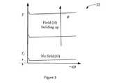
이제부터 도 3과 관련하여, 전형적인 제동 토크(T) 대 전계강도(field strength, H)와 각속도(ω)에 대한 그래프가 도시된다. 항복 토크에 기인 전계 강도는 Ty(H)이며, 이는 예를 들면 전자기 코일(16)(도 1 참조)로 전압(tension) 또는 전류 피드-포워드를 이용하여 조절될 수 있다. B와 Tf는점성이며 건식 마찰 조건이다.정지마찰 현상(stiction phenomenon)이 저속에서 보일 수 있다는 것을 주목하라. 회전자(12) 블레이드와 고정자(14) 블레이드 사이에서 충분한 상대 운동이 있다면, 방정식 1(Equation 1)은 출력 토크의 우수한 근사치이다. 방정식 2(Equation 2)는 방정식 1과 선형 등가이며(토크 T 대신에 선형 힘 F), 이 방정식 2에서

마주보는 반-능동형 서브-액추에이터 개념Opposed Semi-Active Sub-Actuator Concepts
마주보는 반-능동형 서브-액추에이터 개념은 두 개의 유사한 반-능동형 클러치를 이용하며, 이 클러치는 외부 속도원([1], [2], [3], [4] 및 [5])에 의해 반대 방향이지만 동일한 속도로 구동된다. 도 4와 관련하여, 두 개의 반-능동형 액추에이터(SAA)(42, 44)의 출력부들이 함께 연결되어, 마주보는 반-능동형 서브-액추에이터 시스템(40)의 출력 부재(output member, 47)를 형성한다. 예를 들면, MR 클러치와 같은 제 1 SAA (42)의 입력 부재가 예를 들면, 시계방향(clockwise)(CW)과 같이 제 1 방향으로 회전하는 반면, 예를 들면, MR 클러치와 같은 제 2 SAA (44)의 입력 부재가 예를 들면, 반시계방향(clockwise)(CCW)과 같이 제 2 반대 방향으로 회전한다. 제 1 SAA(42)는 시계방향 출력 토크를 제어하는 반면, 출력 부재(46)가 SAA(42, 44)들의 입력 부재(가령, SAA(42 및 44)의 프레임들)보다 더 빨리 회전하지 않는 한, 제 2 SAA(44)는 반시계방향(CCW) 출력 토크를 제어한다.The opposing semi-active sub-actuator concept utilizes two similar semi-active clutches, which are controlled by an external velocity source ([1], [2], [3], [4] and [5]) But in the opposite direction, but at the same speed. 4, the outputs of the two semi-active actuators (SAAs) 42, 44 are connected together to form an output member 47 of the opposing semi-active
부하가 속도원의 관성에서 격리된다는 사실에 추가하여, 많은 장점들이 마주하는 두 개의 유사한 반-능동형 액추에이터들에 있다. 예를 들면, 디자인의 대칭 때문에, (예를 들면, 도 4의 제 1 SAA(42)와 제 2 SAA(44))클러치들의 건식 마찰이 상쇄되며 출력으로 전달되지 않는다. 입력 속도가 유사하다면, 출력 속도가 영이 될 때, 점성 저항(viscous drag)도 상쇄된다(balanced). 항상 클러치에서 상대 운동이 있기 때문에, 정지 마찰이 제거된다. 반-능동형 액추에이터 기술에 기인하여, 클러치 힘이 예를 들면, 두 개 모두의 반-능동형 액추에이터로 전압 또는 전류 피드-포워드를 조절함으로써 신속하고 정확하게 제어된다는 사실이 조합된 이 장점들 때문에, 이 개념은 높은 성능(높은 힘 밀도, 높은 대역폭, 매우 낮은 출력 임피던스 및 고성능의 힘 표시 기능)과 내재된 안전한 힘 공급원를 형성하도록 이용될 수 있다.In addition to the fact that the load is isolated from the inertia of the velocity circle, many advantages reside in the two similar semi-active actuators facing each other. For example, due to the symmetry of the design, the dry friction of the clutches (e.g.,
기계식Mechanical차동장치Differential
기계식 차동장치들은 세 개의 포트들을 가지는 장치이며, 이 포트들 중에서 힘이 후술되는 공지된 관계로 분배된다. 표준 기어박스(standard gearbox), 하모닉 드라이브(harmonic drive), 사이클로이드 기어박스(cycloidal gearbox), 바 매커니즘(bar mechanism), 너트 매커니즘에 대응하는 리드 스크루(lead screw) 또는 볼 스크루(ball screw) 및 케이블 매커니즘, 그 외 다른 것들을 포함하는 임의의 감속 장치(speed reducer)가 기계식 차동장치로써 이용될 수 있다. 레버 유추(lever analogy)가 차동 매커니즘의 작동 원리를 설명하기 위해서 이용될 수 있다. 도 5a와 도 5b는 관성 효과(inertial effect)가 고려되지 않거나(도 5a) 고려된(도 5b) 레버 유추를 설명된다. 관성 효과가 고려되지 않는 경우에(도 5a), 포트(O1, O2 및 O3)들, 속도(


차동 매커니즘의 이용으로 인해 세 개의 포트들을 거쳐서 힘 분배와 더욱 복잡한 실행 원리를 위한 개방된 신규한 형상 가능성을 제공한다. 몇몇 현존하는 차동 결합을 이용한 액추에이터 사이에서, 이러한 가능성이 Lauria 등에 의한 [6], Kim 등에 의한 [7] 및 Chapuis 등에 의한 [8]에 의해 제안된다.The use of a differential mechanism provides an open novel shape possibilities for power distribution and more complex implementation principles through the three ports. Among the actuators using some existing differential coupling, this possibility is proposed by Lauria et al. [6], Kim et al. [7] and Chapuis et al. [8].
반-능동형 이중Semi-active duplex차동Differential 액추에이터 개념 Actuator concept
MR 클러치에서, 하나의 입력 회전 부재와 하나의 출력 회전 부재가 있다. 자기장은 슬립 링(slip ring)을 통하여 연결된 회전 코일(rotating coil) 또는 고정 자석 유동 가이드(fixed magnetic flux guide)에 의해 둘러싸인 고정 코일(stationary coil)에 의해 생성된다. 이로써 MR 클러치는 비교적 복잡해진다. 비교해보면, 출력부는 단지 회전 부재이기 때문에, MR 브레이크는 더 작고 단순하다.In the MR clutch, there is one input rotary member and one output rotary member. The magnetic field is generated by a stationary coil surrounded by a rotating coil or a fixed magnetic flux guide connected through a slip ring. As a result, the MR clutch becomes relatively complicated. In comparison, the MR brakes are smaller and simpler because the output portion is simply a rotating member.
클러치의 이용 때문에, 마주보는 반-능동형 서브-액추에이터 개념을 통합하기에는 복잡하다. 이 결점이 직렬로 연결된 두 개의 클러치들 대신에 차동적으로 결합된 두 개의 브레이크들을 이용함으로써 상당히 감소할 수 있다. 따라서, 본 발명은 입력 속도원에 연결되며 두 개의 기계식 차동 장치를 이용한 시스템의 출력에 연결된 반-능동형 액추에이터들 (브레이크들)를 이용한다. 양 방향에서 두 개의 제동력(braking force)의 조합에 의해 시스템의 출력 힘이 제어될 수 있도록, 이 형상이 형성된다.Due to the use of clutches, it is complicated to incorporate the opposing semi-active sub-actuator concept. This drawback can be substantially reduced by using two differentially coupled brakes instead of two clutches in series. Accordingly, the present invention utilizes semi-active actuators (brakes) connected to the output of the system connected to the input speed source and using two mechanical differentials. This shape is formed so that the output force of the system can be controlled by the combination of two braking forces in both directions.
상기한 바와 같이, 다양한 반-능동형 액추에이터 기술이 본 발명을 구체화하도록 이용될 수 있다. 그러나, 단순화를 위해서, MR 브레이크가 작동 원리를 설명하도록 이용될 것이다.As noted above, various semi-active actuator techniques may be utilized to embody the present invention. However, for the sake of simplicity, the MR brakes will be used to explain the working principle.
반-능동형 이중 차동 액추에이터의 가능한 형상이 상기 액추에이터의 작동 원리를 설명하기 위해 레버 유추를 이용하여 도 6에서 도시된다. 속도원(도시되진 않지만)은

상기 관계들은 작동 원리의 상기 형상에 대한 몇몇 특성을 나타낸다. 마주보는 반-능동형 서브-액추에이터 개념처럼, 건식 마찰 조건이 출력에 전달되지 않도록, 대칭이 형성된다. 출력 속도가 영일 때, 점성력(Viscous force)이 상쇄된다. 항상 브레이크에서 상대 운동이 있기 때문에, 정지 마찰 문제는 제거된다. 항상 개별 차동 매커니즘에서 반동력(reaction force)이 동일한 방향이기 때문에, 백래시(backlash)가 제거된다. 게다가, 도 6과 도 7에서 알 수 있듯이, 출력 힘은 입력 속도원의 움직임에 의해 영향받지 않아서, 정확하게 제어될 필요 없다. 또 다른 특성은, 브레이크의 매우 낮은 출력 관성 때문에, 고유 출력 임피던스가 가령 표준 기어식 EM 모터와 같은 종래의 액추에이터 중 하나와 비교하여 매우 작게 형성될 수 있다는 것이다. 상기 개념에 기초한 액추에이터의 그 외 다른 장점이 후술된다.These relationships represent some characteristics of the shape of the working principle. Like the opposed semi-active sub-actuator concept, symmetry is formed so that dry friction conditions are not transmitted to the output. When the output speed is zero, the viscous force is canceled. Because there is always relative motion in the brakes, the static friction problem is eliminated. Since the reaction force is always in the same direction in the individual differential mechanisms, the backlash is eliminated. In addition, as can be seen in Figures 6 and 7, the output force is not affected by the motion of the input velocity source and need not be precisely controlled. Another characteristic is that, due to the very low output inertia of the brakes, the inherent output impedance can be made very small compared to one of the conventional actuators, such as a standard gear type EM motor. Other advantages of the actuator based on the above concept will be described later.
가능한 형상들Possible shapes
본 발명의 설명을 단순화하기 위해서, 이제부터 복수 개의 가능한 형상 중 세 개의 설명적 형상이 도 7 내지 9를 참조하여 논의될 것이다.To simplify the description of the present invention, from now on, three illustrative shapes of a plurality of possible shapes will be discussed with reference to Figures 7-9.
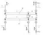
더욱 상세하게는, 도 7에서 설명된 제 1 형상은 기계식 이중 차동 장치 개념을 도입한 도 6에서 이용된 형상과 균등물에, 개별적으로 피봇(O3및 O6)들에 연결된 가령, MR 브레이크(56 및 58)들과 같은 두 개의 반-능동형 액추에이터에 대한 추가한 것이다.More specifically, FIG. 7 is described in the first shape to the shape and the equivalents thereof used in Figure 6 incorporating the dual mechanical differential concept device, individually pivoted (O3 Active actuators, such as the
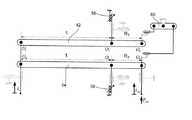
도 8에서 설명된 제 2 형상에서, 개별적으로 피봇(O3 및 O5)들이 두 개의 MR 브레이크(56 및 58)들에 연결되며, 피봇(O2 및 O6)들이 시스템의 출력을 형성하도록 함께 링크되며, 두 개의 차동 장치(52, 54)의 입력 속도 포트(O1 및 O4)들은 동일 방향으로 이동한다. 이중 차동장치 형상 때문에, 출력 힘이 양 방향에서 여전히 제어가능하다.8, individually pivots O3 and O5 are connected to two
도 9에 도시된 제 3 형상에 관하여, 개별적으로 피봇(O2 및 O5)들이 두 개의 MR 브레이크(56 및 58)들에 연결되며, 시스템의 출력을 형성하도록 피봇(O3 및 O6)들이 (제 3 레버로 나타난) 외부 매커니즘(60)에 연결되고, 두 개의 차동 장치(52, 54)들 중 입력 속도 포트(O1 및 O4)도 동일한 방향으로 이동한다. 제동력이 출력힘에 대하여 반대 효과를 주도록 외부 매커니즘(60)이 필요하다.9, pivots O2 and O5 are connected to two
이 설명적 형상들이 예를 들면, 케이블 매커니즘, 대응하는 너트 매커니즘을 이용한 리드 스크루 또는 볼 스크루, 바 매커니즘, 사이클로이드 기어박스 및 유성기어박스, 표준 기어박스, 하모닉 드라이브 등을 이용하여 실행될 수 있다.These illustrative shapes may be implemented using, for example, a cable mechanism, a lead screw or ball screw using a corresponding nut mechanism, a bar mechanism, a cycloid gearbox and a planetary gearbox, a standard gearbox, a harmonic drive,
출력힘이 예를 들면, 두 개의 반-능동형 액추에이터들 모두로 전력 또는 전류 피드-포워드를 조절함으로써 제어될 수 있다. 선택적으로, 또한 출력힘이 출력과 부하 사이에서 힘 센서 또는 토크 센서를 이용한 토크 피브백 제어 기법(torque feedback control scheme)을 이용하여 제어될 수 있다.The output force can be controlled, for example, by adjusting the power or current feed-forward to both of the two semi-active actuators. Optionally, the output force can also be controlled using a torque feedback control scheme using a force sensor or torque sensor between the output and the load.
출력힘이 MR 브레이크(56 및 58)들에 의해 제공된 두 개의 제동력들을 이용하여 양 방향으로 제어가능하기 때문에, 레버(52, 54)들의 길이는 독립적으로 가변할 수 있고, 포트(01 내지 O6)들의 기능(입력 속도원에 링크, 브레이크에 링크 또는 시스템의 출력에 링크)은 본 발명의 특성과 개념으로부터 벗어남이 없이 치환가능하다.
The lengths of the
첨부된 도면에서,
도 1은 단순화된 멀티-블레이드형 자기유변(MR) 브레이크의 횡단면도.
도 2는 MR 브레이크 또는 MR 클러치와 같은 반-능동형 엑츄에이터를 개략적으로 나타내기 위해 이용되는 심볼(symbol)이다.
도 3은 MR 브레이크의 일반적인 토크 커브에 대한 그래프이다.
도 4는 도 1의 단순화된 멀티-블레이드형 MR 브레이크를 이용하여 대립되는 반-능동형 서브-액추에이터들에 대한 횡단면도.
도 5a와 5b에는 각각 관성효과를 고려한 기계적 차동 개념에 대한 개략적인 레버 해석과 관성효과를 고려한 기계적 차동 개념에 대한 개략적인 레버 해석(lever analogy)이다.
도 6은 이중 기계식 차동 개념의 허용가능한 형상에 대한 개략적 레버 해석이다.
도 7은 반-능동형 이중 기계식 차동 액추에이터의 제 1 형상에 대한 개략적 레버 해석이다.
도 8은 반-능동형 이중 기계식 차동 액추에이터의 제 2 형상에 대한 개략적 레버 해석이다.
도 9는 반-능동형 이중 기계식 차동 액추에이터의 제 3 형상에 대한 개략적 레버 해석이다.
도 10은 도 7에 도시된 것과 균등한 형상인 두 개의 유성 기어링 스테이지들을 이용한 반-능동형 이중 기계식 차동 액추에이터에 대한 제 1 실시예의 횡단면의 사시도.
도 11은 도 10의 반-능동형 이중 기계식 차동 액추에이터의 실시예에 대한 서브시스템의 세부사항에 대한 분해 사시도.
도 12는 도 11의 감속 및 역전 스테이지의 속도 방향에 대한 개략도.
도 13은 도 10의 반-능동형 이중 기계식 차동 액추에이터가 가지는 MR 브레이크에 대한 횡단면 사시도.
도 14는 도 10의 반-능동형 이중 기계식 차동 액추에이터가 가지는 MR 브레이크의 분해 사시도.
도 15는 도 10의 반-능동형 이중 기계식 차동 액추에이터의 이중-차동 매커니즘에 대한 단순화된 사시도.
도 16은 도 8에 도시된 일 형상과 균등한 형상인 두 개의 하모닉 드라이브 기어링 스테이지를 이용한 반-능동형 이중 기계식 차동 액추에이터의 제 2 실시예에 대한 사시도.
도 17은 도 16의 반-능동형 이중 기계식 차동 액추에이터에 대한 분해 사시도.
도 18은 도 16의 반-능동형 이중 기계식 차동 액추에이터가 가지는 이중 차동 매커니즘에 대한 단순화된 횡단면도.
도 19는 도 16의 반-능동형 이중 기계식 차동 액추에이터가 가지는 두 개의 MR 브레이크 내에서 입력 전압에 대한 함수로써 토크 출력을 나타낸 그래프.
도 20은 도 16의 반-능동형 이중 기계식 차동 액추에이터를 이용한 전압 피드포워드 토크 제어기에 대한 예를 나타낸 개략도.
도 21은 느린 사인 명령에 대한 도 20의 제어기의 토크 응답을 나타낸 그래프.
도 22는 도 9에 도시된 일 형상과 균등한 형상인 두 개의 유성 기어링 스테이지들을 이용한 제 3 실시예인 이중 차동 매커니즘에 대한 사시도. 및
도 23a와 도 23b는 도 8에 도시된 일 실시예와 균등한 형상인 두 개의 유성 기어열(gearing train)을 이용한 반-능동형 이중 기계식 차동 액추에이터에 대한 제 4 실시예의 두 개의 변형예들에 대한 개략도들.In the accompanying drawings,
1 is a cross-sectional view of a simplified multi-blade type magnetic rheological (MR) brake.
Figure 2 is a symbol used to schematically represent a semi-active actuator such as an MR brake or an MR clutch.
3 is a graph of a typical torque curve of an MR brake.
Figure 4 is a cross-sectional view of opposing semi-active sub-actuators using the simplified multi-blade type MR brakes of Figure 1;
Figures 5a and 5b show a schematic lever analysis of the concept of mechanical differential in consideration of the inertia effect and a schematic lever analysis of the mechanical differential concept in which the inertia effect is considered.
Figure 6 is a schematic lever analysis for an acceptable shape of the dual mechanical differential concept.
Figure 7 is a schematic lever analysis for a first configuration of a semi-active dual-mechanical differential actuator.
Figure 8 is a schematic lever analysis for a second shape of a semi-active dual mechanical differential actuator.
9 is a schematic lever analysis for a third shape of a semi-active dual-mechanical differential actuator.
10 is a perspective view of a cross-sectional view of a first embodiment of a semi-active dual-mechanical differential actuator using two planetary gearing stages in a shape equivalent to that shown in Fig.
11 is an exploded perspective view of the details of the subsystem for an embodiment of the semi-active dual-mechanical differential actuator of FIG. 10;
12 is a schematic view for the speed direction of the decelerating and reversing stage of FIG. 11;
Fig. 13 is a cross-sectional perspective view of the MR brake of the semi-active dual-acting differential actuator of Fig. 10; Fig.
Fig. 14 is an exploded perspective view of the MR brake of the semi-active dual-acting differential actuator of Fig. 10; Fig.
Figure 15 is a simplified perspective view of the dual-differential mechanism of the semi-active dual-mechanical differential actuator of Figure 10;
16 is a perspective view of a second embodiment of a semi-active dual-mechanical differential actuator using two harmonic drive gearing stages of the same shape and the same shape shown in Fig.
Figure 17 is an exploded perspective view of the semi-active dual-mechanical differential actuator of Figure 16;
Figure 18 is a simplified cross-sectional view of the dual differential mechanism of the semi-active dual-mechanical differential actuator of Figure 16;
19 is a graph showing the torque output as a function of the input voltage in the two MR brakes of the semi-active dual-acting differential actuator of Fig.
Figure 20 is a schematic diagram illustrating an example of a voltage feed forward torque controller using the semi-active dual-mechanical differential actuator of Figure 16;
Figure 21 is a graph showing the torque response of the controller of Figure 20 for a slow sine command.
22 is a perspective view of a dual differential mechanism that is a third embodiment using two planetary gearing stages in one shape and the equivalent shape shown in Fig. And
Figs. 23A and 23B are diagrams for two variants of the fourth embodiment for a half-active dual-mechanical differential actuator using two planetary gearing trains of equal shape to the embodiment shown in Fig. Schematic diagrams.
반-능동형 이중Semi-active duplex차동Differential 액추에이터에 대한 설명적 Explanatory to the actuator실시예Example
제 1 설명적First Explanatory실시예Example
제 1 설명적 실시예에서, 도 10 내지 15를 참조하면, 두 개의 유성 기어링 스테이지들이 도 7에 도시된 일 형상과 균등한 이중 차동 장치에서 이용된다. 일반적으로, 상기 제 1 설명적 실시예는 더욱 상세하게 설명될 다음과 같은 사항을 포함한다.In the first illustrative embodiment, referring to Figs. 10-15, two planetary gearing stages are used in a dual differential device equivalent to the shape shown in Fig. In general, the first illustrative embodiment includes the following items to be described in more detail.
● 전자기(EM) 모터와 속도 감속 및 역전 스테이지를 포함하는 입력 속도원, 두 부재들은 속도원의 출력을 형성하는 방향으로 반대되는 속력으로 이동한다.• An input speed source, including electromagnetic (EM) motors and speed reduction and reversing stages, the two members move at opposite speeds in the direction of the output of the speed source.
● 입력 속도원, 두 개의 MR 브레이크들 및 시스템의 출력에 결합된, 두 개의 유성 기어링 스테이지에 기초한 이중 차동 매커니즘 및● Dual differential mechanism based on two planetary gearing stages, coupled to input speed circle, two MR brakes and the output of the system, and
● 액추에이터 주 체적 내부에 선택적으로 포함된 제어 및 구동 전자장치.Control and drive electronics optionally contained within the actuator main volume.
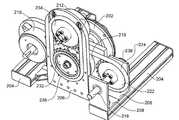
도 10 내지 15와 관련하여 더욱 상세하게는, 속도원을 형성하기 위해서, (하우징 본체(102a)와 두 개의 하우징 단부(102b 및 102c)를 구비한) 하우징(102)이 (도시되진 않지만) 기준 프레임(reference frame)에 기계적으로 고정된다. EM 모터(104)의 회전자가 기어(108)와 맞물린 피니언(pinion, 106)에 부착된다. 기어(108) 자체는 제 1 속도원 출력을 형성하는 기어(112)와 맞물린 피니언(108)에 부착된다. 또한 기어(108)는 제 2 속도원 출력을 형성하는 기어(118)와 맞물린 피니언(116)에 부착되는 기어(114)와 맞물린다. 두 개의 출력 속도들은 도 11 및 도 12에서 화살표에 의해 개략적으로 표시된 바와 같이 반대 방향으로 이동한다.More specifically with reference to Figures 10 to 15, a housing 102 (with
가령, 기어(112 및 118)들과 같은 속도원 출력을 기계식 차동 입력 포트들에 링크하기 위해서, 기어(112)는 샤프트의 움직임이 베어링(bearings, 124 및 126)들에 의해 가이드 되는 샤프트(122)를 관통하여 선기어(sun gear, 130)에 부착된다. 기어(118)는 중공 샤프트(128)를 관통하여 선기어(120)에 부착되고, 이 중공 샤프트는 샤프트 상으로 자유롭게 회전하여서, 중공 샤프트의 움직임이 샤프트(122)에 의해 가이드된다.The
두 개의 유성 기어링 스테이지들이 이중 차동 매커니즘을 형성하기 위해 이용된다. 차동 장치 형상에서 하나의 유성 기어링이 도 7의 레버(52 또는 54)들 중 하나에 대응되며, R은 애눌러스 기어(annulus gear)에 대한 선기어가 가지는 톱니 수의 비율이다. 차동 기능은 전방 위성 캐리어(134)와 후방 위성 캐리어(136)(포트 O2 및 O5) 상에 장착된 위성 기어(132)와, 그리고 애뉼러스 기어(138 및 140)들(포트 O3 및 O6)과, 선기어(120 및 130)들 (포트 O1 및 O4)의 상호 작용에 의해 실현된다. 두 개의 유성 기어링 스테이지의 위성 기어들은 위성 캐리어 샤프트(142)들 상에서 자유롭게 회전하며, 이 위성 캐리어 샤프트들은 전방 위성 캐리어(134)와 후방 위성 캐리어(136)에 의해 지지되며, 이 전방 위성 캐리어와 후방 위성 캐리어의 움직임은 베어링(144 및 190)들에 의해 가이드된다. 상기 제 1 설명적 실시예에서, 로드(146)들은 전방 위성 캐리어(134)와 후방 위성 캐리어(136)의 강도(rigidity)를 증가시키도록 이용된다.Two planetary gearing stages are used to form the dual differential mechanism. In the differential configuration, one planetary gearing corresponds to one of the
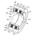
특히 도 13 및 도14과 관련하여, MR 브레이크(148 및 150)들의 회전자들은, 너트(156)에 의해, 애눌러스 기어(138 및 140)들에 체결된 다수의 회전자 블레이드(152)들과 회전자 스페이서(rotor spacer, 154)들에 의해 형성된다. 반면에, 하우징 본체(102a)에 체결된 MR 브레이크(148 및 150)들의 고정자들은 링(161)의 많은 고정자 블레이드들과 고정자 스페이서들, 전자기 코일(162 및 164)의 많은 고정자 블레이드들과 고정자 스페이서들 및 자속 가이드 부품(magnetic flux guide part)(166, 168, 170 및 172)들의 많은 고정자 블레이드(158)들과 고정자 스페이서(160)들에 의해 형성된다. 회전자 블레이드(152)와 고정자 블레이드(158) 사이의 틈(174)들은 MR 유체로 충진된다. 밀봉 요소(176, 178, 180 및 182)들은 MR 유체를 한정하도록 이용된다. 전류가 코일(162 및 164)들 중 하나를 통하여 흐를 때, 자기장이 발생하며 개별적으로 가령, 대응하는 브레이크 (148 및 150)의 MR 유체를 통하여 가이드된다. 결과적으로, 브레이크(148 또는 150)는 고정자에 대한 회전자(개별적으로, 애눌러스 기어)(138 또는 140))의 회전을 방해한다.13 and 14, the rotors of the
이제 도 15에 관하여, 출력 샤프트(output shaft, 188)에서 출력 토크(output torque, 200)를 초래하는, 개별적으로 애눌러스 기어(138 및 140)들의 제동 토크(194 및 198)들뿐만 아니라, 개별적으로 선기어(120 및 130)들의 입력 속도들의 방향(192 및 196)이 나타난다.Referring now to FIG. 15, the braking torques 194 and 198 of the individual compression gears 138 and 140, which result in an
앞선 도 10에 대하여, 제어 및 구동 전자장치(184)는 MR 브레이크(148 및 150)의 전자기 코일(162 및 164)에 공급되는 전기 에너지를 조절함으로써 두 개의 제동력 및 EM 모터(104)의 회전을 제어한다. 제어 및 구동 전자장치(184)들은 액추에이터의 주된 체적 내부에 선택적으로 포함된다. 채용된 제어 기법에 따라, 선택적인 인코더(encoder, 186)가 베어링(144 및 190)들에 의해 가이드된 출력 샤프트(188)의 움직임을 감지하도록 이용될 수 있다.
10, the control and drive
제 2 설명적The second illustrative실시예Example
제 2 설명적 실시예에서, 도 16 내지 18을 참조하면, 두 개의 하모직 구동 기어링 스테이지(harmonic drive gearing stage)가 도 8에 도시된 형상과 균등한 이중 차동 장치 형상으로 이용된다. 일반적으로, 상기 제 2 설명적 실시예는 더욱 세부적으로 다음과 같은 것을 포함한다.In the second illustrative embodiment, referring to Figures 16-18, two harmonic drive gearing stages are used in a dual differential device configuration equivalent to the configuration shown in Figure 8. < RTI ID = 0.0 > In general, the second illustrative embodiment includes the following in more detail.
● 전자기(EM) 모터에 의해 형성된 입력 속도원,● Input speed circle formed by electromagnetic (EM) motor,
● 입력 속도원, 두 개의 MR 브레이크들 및 시스템의 출력에 결합되며, 두 개의 하모닉 구동 기어링 스테이지에 기초한, 이중 차동 매커니즘,• Dual-differential mechanism based on input speed circle, two MR brakes and the output of the system, based on two harmonic drive gearing stages,
●제어 및 구동 전자장치.• Control and drive electronics.
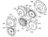
더욱 상세하게는, 도 16 내지 18과 관련하여, 속도원을 형성하기 위해서, EM 모터(202)의 본체, 지지 베이스(support base, 204), 지지 플레이트(206)들, 지지 브라켓(support bracket, 208)들 및 MR 브레이크들의 본체(210 및 212)들이 기계적으로 접지된다. EM 모터(202)의 출력 샤프트(214)는 이중 차동 매커니즘(216)의 입력 포트들에 연결된 속도원을 형성한다(도 17 참조).More specifically, with reference to FIGS. 16 through 18, the main body of the
두 개의 HD 기어링 스테이지는 기계식 이중 차동 매커니즘(216)을 형성하기 위해 이용되며 이 기계식 이중 차동 매커니즘이 나타난 도 18은 단순화된 단면도를 나타낸다. 일반적으로, HD 기어박스는 1)웨이브 제너레이터(wave generator)(WG); 2)가요성 스플라인(flexible spline)(FS) 및 원형 스플라인(circular spline)(CS)의 세 개의 부품으로 구성된다. 이용된 두 개의 HD 기어링 세트는 FS와 함께 회전하는 역학적 스플라인(dynamic spline)(DS)이라 불리는 4번째 부품을 가진다. HD 기어링 스테이지는 도 8의 레버(52, 54)들 중 하나로 볼 수 있고, 도 8의 O1/O4는 WG로써, O2/O5는 CS로써, O3/O6는 FD/DS로써 볼 수 있고, R은 FD/DS의 톱니 수로 나누면 2와 동일하다. WG(포트 O1 및 O4) 모두는 EM 모터(202)의 출력 샤프트(214)에 체결된다. 제 1 HD 기어링 스테이지의 CS(O2)는 제 2 HD 기어링 스테이지의 FS(O6)에 체결된다. 그 이후에 이 조립체는 풀리(220 및 222)들과 벨트(224)를 관통하여 시스템의 출력 샤프트(218)에 연결된다. 제 1 기어링 스테이지의 DS(O3)는 풀리(226 및 228)들과 벨트(230)를 관통하여 MR 브레이크(210)에 링크된다. 최종적으로 제 2 기어링 스테이지의 CS(O5)는 풀리(232 및 234)들과 벨트(236)를 관통하여 MR 브레이크(212)에 링크된다. 4-지점 접촉 베이링(four-point contact bearing, 239)은 풀리들의 움직임을 가이드하도록 이용되며 기어링 요소들에 부착된다. 기계식 이중 차동 매커니즘(216)은 벨트(224)를 관통하여 출력 샤프트(218)로 링크(240)에서, 벨트(230)를 관통하여 MR 브레이크(210)로 링크(241)에서 및 벨트(236)를 관통하여 MR 브레이크(212)로 링크(242)에서 링크된다.Two HD gearing stages are used to form the mechanical dual
상업적으로 이용가능한 MR 브레이크들이 예를 들면, 가령 LORD 회사[10]로부터 이용가능한 것들과 같은 MR 브레이크(210 및 212)들로 이용될 수 있다.Commercially available MR brakes may be used, for example, as
(도시되진 않지만)제어 및 구동 전자장치는 MR 브레이크(210 및 212)들로 공급되는 전기 에너지를 조절함으로써 두 개의 제동력과 EM 모터(202)의 회전을 제어한다. 채용된 제어 기법에 따라서, 광학적 엔코더(optional encoder, 238)가 출력 샤프트(218)의 움직임을 감지하도록 이용될 수 있다.The control and drive electronics (not shown) control the two braking forces and the rotation of the
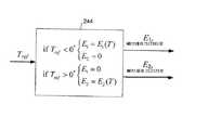
예를 들면, 제어기는 전압(electrical tension) 피드-포워드 토크 제어 기법을 이용할 수 있다. 이 기법에서, MR 브레이크(210 및 212)(E1 및 E2)들에 적용된 전력과 출력 토크(T) 사이 관계가 처음으로 확인한다. 이러한 목적을 위해서, 모터(202)는 등속도로 회전하도록 설정되며, 느리게 가변하는 사인파형의 전압이 MR 브레이크(210 및 212)들로 보내진다. 출력 토크는 방해된 출력 움직임으로 측정된다. 데이터와 피팅된 선형 곡선들이 도 19에서 제시된다. 부분적으로 선택된 형상의 비대칭성 때문에, 커브들은 정확하게 0 (Nm)에서 교차하지 않지만, 상당히 작은 토크 값(0*)에서 교차한다. 도 6의 형상과 반대로, MR 브레이크(210 및 212)들의 마찰의 작은 부분이 출력으로 전해진다. 도 20은 도 19에서 나온 테이터를 이용하여 전압 피드-포워드 토크 제어기(244)의 설명적인 예시를 나타내며, 도 21은 도 20의 제어기를 이용하여 방해된 출력 움직임을 포함한 느린 사인형 토크 명령에 대한 토크 응답을 나타낸다.
For example, the controller may utilize electrical tension feed-forward torque control techniques. In this technique, the relationship between the power applied to the
제 3 설명적Third Explanatory실시예Example
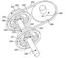
도 22를 참조하면 제 3 설명적 실시예에서, 두 개의 유성 기어링 스테이지가 도 9에서 도시된 일 형상과 균등한 이중 차동 형상으로 이용된다.Referring to Fig. 22, in the third illustrative embodiment, two planetary gearing stages are used in a dual differential configuration equivalent to the configuration shown in Fig.
속도원(246)은 속도(249 및 251)들과 함께 회전하는 선기어(248 및 250)들(포트 O1 및 O4)에 연결된다. 유성 캐리어(252 및 254)들(포트 O2 및 O5)은 제동 토크(253 및 255)를 생성하는 (도시되진 않지만) MR 브레이크들에 연결된다. 애눌러스 기어(256 및 258)들(포트 O3 및 O6)은 케이블 또는 벨트(264)를 구동시키는 풀리(260 및 262)들에 체결된다. 시스템의 출력부는 풀리(266)이다. 풀리(260, 262, 266)들과 케이블 또는 벨트(264)는 도 9의 외부 매커니즘(60)을 구성하며, 이 외부 매커니즘은 두 개의 제동 토크가 출력 토크(268)에 반대 효과를 미치도록 이용된다.
제 4 설명적Fourth illustrative실시예Example
도 23a 또는 도 23b를 참조하면 제 4 설명적 실시예에서, 유성 기어열은 도 8에서 도시된 일 형상과 균등한 이중 차동 형상으로 이용된다. 도 23a 및 도 23b은 이중 차동와 높은 감속율(reduction ratio)을 가질 수 있는 두 개의 변형예로 나타낸다. 도 8의 R1 및 R2는 방정식 8 및 방정식 9에 의해 설명된 바와 같이 기어링 요소의 상대 톱니에 대한 함수이며, 여기에서 ni 는 기어(i)의 톱니 수이다.Referring to FIG. 23A or 23B, in the fourth illustrative embodiment, the planetary gear train is used in a dual differential shape equivalent to the shape shown in FIG. Figures 23A and 23B show two variants that can have dual differential and high reduction ratios.
도 23a 및 도 23b 모두에서, 입력 샤프트(270)(포트 O1 및 O4)는 (도시되진 않지만) 속도원에 링크된다. 샤프트(272)(포트 O3)는 (도시되진 않지만) 제 1 브레이크로 링크되며, 샤프트(274)(포트 O5)는 (도시되진 않지만) 제 2 브레이크로 링크되며, 샤프트(276)(포트 O2 및 O6)는 시스템의 출력으로 작동한다. 유성 기어(278)는, 그 자체로 유성 기어(282)보다 더 많은 기어를 가진 유성 기어(280)보다 더 많은 톱니를 가진다. 제동 토크가 샤프트(272)에 가해진다면 그리고 제동 토크가 샤프트(274)에 가해진다면, 토크는 전달된 방향과 반대 방향에서 샤프트(276)로 전달된다.23A and 23B, the input shaft 270 (ports O1 and O4 ) is linked to the velocity source (although not shown). Shaft 272 (ports O3) are (but not shown) is linked to a first brake, a shaft 274 (ports O5) is (but not shown) is linked to the second brake, a shaft 276 (port O2 and O6 ) act as the output of the system. The

비록 상기 설명적인 실시예에서 속도원으로써 EM 모터가 주로 참조되었을지라도, 본 발명의 목적을 위한 이 속도원은 가령, 예를 들면 기어식 동력(powered geared) EM 모터 또는 직접-구동식 EM 모터, 압전 모터(piezoelectric motor), 수압 모터(hydraulic motor) 또는 수압 액추에이터, 공압 모터(pneumatic motor) 또는 공압 액추에이터 또는 내연 기관(combustion engine), 터빈 등과 같은 움직임을 제공할 수 있는 임의의 기계적 동력원으로 간주된다.
Although the EM motor is primarily referred to as the velocity source in the above illustrative embodiment, the velocity source for the purposes of the present invention may be, for example, a geared powered EM motor or a direct-drive EM motor, Is considered to be any mechanical power source capable of providing motion such as a piezoelectric motor, a hydraulic motor or a hydraulic actuator, a pneumatic motor or a pneumatic actuator or a combustion engine, a turbine, .
반-능동형 이중Semi-active duplex차동Differential 액추에이터 개념의 장점 Benefits of the actuator concept
반-능동형 이중 차동 액추에이터 개념의 공통적인 장점은 다음과 같은 사항을 포함한다.Common advantages of the semi-active dual differential actuator concept include the following:
액추에이터가 가령, 디자인된 MR 브레이크로써 신속한 반-능동형 액추에이터를 이용한다면, 힘은 넓은 대역폭으로 제어될 수 있다. 또한, 이 디자인은 빠른 힘, 임피던스 또는 위치 제어 업무를 위해 적합하다. 또한, 큰 대역폭도 로봇 상호작용 적용예에서 직면한 안정성 문제에 대해 유용하다.If the actuator utilizes a fast semi-active actuator, for example as a designed MR brake, the force can be controlled in a wide bandwidth. Also, this design is suitable for fast power, impedance or position control tasks. In addition, large bandwidth is also useful for stability problems encountered in robotic interaction applications.
출력 임피던스는 속도원에서 대부분 완화될 수 있기 때문에, 출력 임피던스는 예외적으로 낮게 형성될 수 있다. 낮은 출력 관성 액추에이터는 매우 낮은 힘과 임피던스에서 더욱 잘 실행되고 더욱 안전하게 상호작용 업무를 수행할 수 있다. 게다가, 작은 관성은 신속하게 가속되고 감속되는 능력을 향상시키며 더 신속한 움직임과 증가된 생산성을 갖게 한다.Since the output impedance can be largely mitigated at the rate source, the output impedance can be exceptionally low. Low output inertia actuators are able to perform better interactively and more securely at very low forces and impedances. In addition, small inertia improves the ability to accelerate and decelerate quickly, and has faster movement and increased productivity.
예를 들면, 액추에이터 힘 또는 임피던스는 MR 브레이크에서 피드-포워드 전압 또는 전류를 조절함으로써 제어될 수 있다. 이러한 제어는 실행 변환기와 감지 변환기 사이에서 있는 구성 모드들에 의해 불안정화될 수 있는 힘 피드백 루프(force feedback loop)에 의존하지 않는다. 안정성 관심은 힘 피드백에 의존한 다수의 이전 접근에 대한 힘과 임피던스 제어 성능을 제한해왔다.For example, the actuator force or impedance can be controlled by adjusting the feed-forward voltage or current in the MR brake. This control does not rely on a force feedback loop that can be destabilized by the configuration modes that exist between the execution converter and the sense converter. Stability concerns have limited the force and impedance control capabilities for many previous approaches that rely on force feedback.
액추에이터는 넓은 역학적 힘 범위를 거쳐서 고성능의 힘 제어를 나타낼 수 있다. 기어식 모터에서, 힘 증폭 트랜스미션(force amplification transmission)은 힘 출력에 모델링하기 힘든 많은 노이즈를 추가한다. 이 노이즈는 운동학적 불완전성, 백래시, 정지 마찰 및 비선형 마찰에서 기인한다. 제안된 개념은 실질적으로 추가적인 힘 증폭에 대한 필요 없이 직접적으로 큰 힘들을 생성하도록 높은 힘-밀도을 가진 반-능동형 액추에이터를 이용할 수 있다. 결과적으로, 브레이크들은 최소한의 기어링를 통하여 출력에 링크될 수 있어서, 제동력들이 정확하게 제어될 수 있다면, 액추에이터는 넓은 동역학적 범위를 거쳐서 고성능의 힘 제어를 나타낸다.Actuators can exhibit high-performance force control over a wide dynamic force range. In gear motors, a force amplification transmission adds a lot of noise to the force output that is difficult to model. This noise is due to kinematic imperfection, backlash, static friction, and nonlinear friction. The proposed concept can utilize semi-active actuators with high force-density to produce large forces directly without the need for substantially additional force amplification. As a result, the brakes can be linked to the output through minimal gearing, so that if the braking forces can be accurately controlled, the actuators exhibit high performance force control over a wide dynamic range.
어떠한 힘도 액추에이터에 의해 생성되지 않을 때, 역구동성(Backdrivability)은 출력을 이동하도록 요구된 최소한의 힘에 대한 측정이다. 때때로, 이 개념은 액추에이터에 의해 제어된 임피던스와 힘에 대한 성능과 안정성을 논의를 위해 이용되어왔다. 낮은 고유의 출력 임피던스 때문에, 이 디자인은 매우 역구동적(backdrivable)이다.When no force is generated by the actuator, Backdrivability is a measure of the minimum force required to move the output. Occasionally, this concept has been used to discuss the performance and stability of impedances and forces controlled by actuators. Because of its low inherent output impedance, this design is highly backdrivable.
이 디자인은 튼튼하며 충격에 강하다. 초과된 에너지가 브레이크에서 단순히 상쇄되는 충돌 동안조차도, 항상 출력 힘이 제어된다. 알려지지 않은 환경과 상호작용할 때, 약한 임의의 트랜스미션 부품 또는 센서도 공통적으로 직면한 펄스 힘을 받지 않는다.This design is strong and impact resistant. The output force is always controlled, even during impact where excess energy is simply canceled out of the brakes. When interacting with an unknown environment, any weak transmission parts or sensors are not subjected to a commonly encountered pulse force.
제안된 개념은 합리적인 비용으로 제작될 수 있다. 상기된 충격 완화 효과에 의해 가령, 큰 관성, 긴 시간 상수들 또는 부정확한 속도 제어를 가진 가령 적은 양의 입력 속도원 하나를 이용하는 것이 가능하다. 게다가, 감속 또는 역전 스테이지의 연결된 기어링은 다수의 비-선형 마찰을 방지할 수 있다. 이들 중 어떠한 것도 액추에이터 출력에 전달되지 않는다. 추가적으로, 백래시가 힘의 내부 반대작용에 의해 제거되기 때문에, 기어링은 큰 공차(tolerance)를 가지게 기계가공될 수 있다.The proposed concept can be made at a reasonable cost. It is possible, for example, to use one of a small amount of input velocity source with large inertia, long time constants or inaccurate velocity control by the above-mentioned shock-mitigating effect. In addition, the linked gearing of the decelerating or reversing stages can prevent a plurality of non-linear friction. Neither of these is transmitted to the actuator output. Additionally, since the backlash is removed by internal opposing forces, the gearing can be machined to have a large tolerance.
백래시의 제거는 위치 제어 업무의 정확성을 향상시키는데 유익하다. 또한, 이로 인해 위치 제어기 또는 속도 제어기의 안정성을 포함하지 않고 액추에이터와 부하 사이에서 높은 관성이 미스매치를 하게 한다.Elimination of backlash is beneficial in improving the accuracy of position control tasks. This also causes high inertia mismatch between the actuator and the load without including the stability of the position controller or speed controller.
이 액추에이터는 여분의 작동(redundant actuation)에 적합하다. 액추에이터의 수가 자유도 수보다 더 많다면, 로봇 시스템은 여분의 작동을 형성한다. 여분의 작동이 평행한 매니플레이터(manipulator)가 가지는 엔드-이펙터의 강성( end-effector stiffness)를 향상시키고, 특이성으로 인해 제어되지 않은 작동을 제거하며, 업무 공간 내에서 더욱 동종의 힘 출력이 나오게 한다고 공지되어 있다. 위치 내의 임의의 에러도 시스템을 망치거나 불안정화할 수 있는 큰 내부 힘을 초래할 수 있기 때문에, 종래의 (스티프) 액추에이터는 여분의 작동을 위해 쉽게 이용될 수 없다. 상기 반-능동형 이중 차동 액추에이트가 용이하게 역구동할 수 있기 때문에, 제안된 반-능동형 이중 차동 액추에이트는 여분의 구동을 위해 적합하다.This actuator is suitable for redundant actuation. If the number of actuators is greater than the number of degrees of freedom, then the robot system forms an extra operation. The redundant operation improves the end-effector stiffness of the parallel manipulator, eliminates uncontrolled operation due to the specificity, and produces more homogeneous force output within the workspace . Conventional (stiff) actuators can not be readily used for redundant operation, because any error in position can result in large internal forces that can ruin or destabilize the system. Since the semi-active dual differential actuator can be easily reversed, the proposed semi-active dual differential actuator is suitable for redundant drive.
이 원리에 대한 또 다른 이점은 상이하게 실행되는 조인트에 기계적 동력을 전달하는 기계식 버스(mechanical bus)를 이용하는 가능성을 형성하는 것이다. 일반적으로, 다수의 자유도를 가지는 구동 시스템은 개별 조인트용 모터를 가진다. 개별 액추에이터는 초기 유형(예를 들면, 전기적 에너지)에서 나온 에너지를 기계적 에너지로 변환한다. 개별 액추에이터는 변형을 실행하기 위한 특정 중량과 체적을 요한다. 하나의 기계식 에너지원을 이용하여 복수의 조인트를 실행하게 하고, 몇몇 적용예에서, 이로써 전체의 복잡성, 체적 및 질량을 낮추는 개념이 기계식 버스이다.
Another advantage to this principle is the possibility of using a mechanical bus to transfer mechanical power to differently executed joints. Generally, a drive system with multiple degrees of freedom has motors for individual joints. The individual actuators convert the energy from the initial type (e. G., Electrical energy) into mechanical energy. Individual actuators require specific weight and volume to perform the deformation. A mechanical energy source is used to execute multiple joints, and in some applications, the concept of lowering overall complexity, volume, and mass is thus a mechanical bus.
반-능동형 이중Semi-active duplex차동Differential 액추에이터 개념의 적용 Application of actuator concept
특히, 상기 본 발명의 설명적 실시예는 비-배타적으로 로봇 시스템과 매커니즘에서 통합을 위한 고성능 액추에이터의 디자인에 적합하다. 환경에 대한 안전하고, 신속하고, 정확거나 다용도를 요구하는 다수의 로봇 업무는 이러한 디자인에 유익할 수 있다. 이 적용 분야는 후술되는 것들 중 다수를 포함한다.In particular, the illustrative embodiment of the present invention is suitable for non-exclusively designing high performance actuators for integration in robotic systems and mechanisms. Many robotic tasks that require safe, fast, accurate, or versatile environments can benefit from this design. This application includes many of the following.
신속 및/또는 정밀한 조립 업무를 위한 로봇 암에 대한 구동,Driving to a robot arm for fast and / or precise assembly tasks,
신속 및/또는 정밀한 절삭 작업을 위한 (레이저 유형을 포함한) 로봇 절단 기계에 대한 구동,Driving for robot cutting machines (including laser type) for rapid and / or precise cutting operations,
재활(rehabilitation), 물리치료(physiotherapy) 및 근육 또는 신경 운동 로봇 시스템에 대한 구동,Rehabilitation, physiotherapy and driving for muscle or neuro-motorized robotic systems,
인간 환경(human environment) 내에서 작동하는 안전한 로봇 암에 대한 구동,Driving for a secure robotic arm operating in a human environment,
안전하고 튼튼한 로붓 장남감에 대한 구동,Driving for safe and durable robust toys,
햅틱 인터페이스(원격-현실(tele-presence), 원격 작동 및 가상 현실)에 대한 구동,Driving for haptic interfaces (tele-presence, remote operation and virtual reality)
유선에 의한 조정 햅틱 구동 휠에 대한 구동,Driving for a coordinated haptic drive wheel by wire,
로봇 차량을 위한 힘 또는 임피던스 제어 휠 및 조인트에 대한 실행,Force or Impedance Control for a Robot Vehicle Execution on wheels and joints,
인공 기관(prostheses) 또는 오르테시스(ortheses)에 대한 구동,Driving for prostheses or ortheses,
힘 증대 및 작업 보조 외골격에 대한 실행,Power-up and task-assisted execution on the exoskeleton,
폴리싱 또는 그린딩용 로붓의 실행,Execution of the strobe for polishing or grinding,
하이퍼-모터식 로봇 매커니즘에 대한 실행,Implementation of a hyper-motorized robot mechanism,
업무를 실행하기 위해서 함께 작업하는 로봇 암에 대한 작동,The operation of a robot arm working together to perform a task,
수술용 로봇에 대한 작동Operation for surgical robots
인간형 로봇을 위한 팔, 다리에 대한 작동Works for arms and legs for humanoid robots
알려지지 않은 환경 내에서 가변적인 형상 물체를 조작하는 임의의 로봇Any robot that manipulates variable geometry objects in an unknown environment
로봇 시스템이 알려지지 않은 환경 내에서의 임의의 작업,If the robot system is in an unknown environment,
제어 힘 또는 제어 토크를 요하는 임의의 작업,Any task requiring control force or control torque,
더 신속한 움직임을 하도록 더 작은 출력 관성을 요하는 임의의 작업,Any task that requires a smaller output inertia for faster motion,
더 안전한 움직임을 하도록 더 작은 출력 관성을 요하는 임의의 작업,Any task that requires a smaller output inertia for a safer motion,
정밀한 위치설정 및/또는 제어 안정성을 향상시키기 위해 적은 백래쉬를 요구하는 임의의 작업,Any task that requires less backlash to improve precision positioning and / or control stability,
하나의 기계적 동력원으로부터 다수의 비행 플랩(flap)에 대한 실행Execution of multiple flight flaps from a single mechanical power source
하나의 기계적 동력원으로부터 다수의 헬리콥터 날(helicopter blade)에 대한 실행, 및Execution of a plurality of helicopter blades from a single mechanical power source, and
기계적 버스 개념이 유용한 임의의 실행.
A random execution of the mechanical bus concept is useful.
본 발명은 상기 설명과 첨부된 도면에서 설명된 구성과 부품에 대한 세부사항으로 본 발명의 적용을 제한하지 않는다고 이해된다. 본 발명은 다양한 방식으로 실행되며 또 다른 실시예를 가질 수 있다. 또한, 본 명세서에서 이용된 용어 또는 전문용어는 설명의 목적이며 제한의 목적이 아니다.It is to be understood that the invention is not to be limited in its application to the details of construction and parts described in the foregoing description and the accompanying drawings. The invention may be practiced in various ways and have other embodiments. Also, the terms or terminology used herein are for the purpose of description and not of limitation.
따라서, 비록 본 발명은 본 발명의 예시적인 실시예를 비-제한적으로 위에서 설명해왔으며, 이 실시예들은 본 발명의 특성과 개념에서 벗어남 없이, 첨부된 청구범위의 범위 내에서 수정될 수 있다.
Thus, although the present invention has been described above with non-limiting exemplary embodiments of the invention, these embodiments may be modified within the scope of the appended claims without departing from the spirit and scope of the invention.
참조문헌들References
[1] M. Sakguchi, J. Furusho, "Development of ER actuators and their applications to force display systems", IEEE Virtual Reality Annual International Symposium, 1998, p 66-70.[1] M. Sakuchi, J. Furusho, "Development of ER Actuators and Their Applications to Force Display Systems", IEEE Virtual Reality Annual International Symposium, 1998, pp. 66-70.
[2] S. B. Choi, S. S. Han, H. K. Kim, CC. Cheong, "H infinity control of a flexible gantry robot arm using smart actuators", Mechatronics 9(3):271- 86, 1999.[2] S. B. Choi, S. S. Han, H. K. Kim, CC. Cheong, "H infinity control of a flexible gantry robot arm using smart actuators ", Mechatronics 9 (3): 271-86, 1999.
[3] H. Hakogi, M. Ohaba, N. Kuramochi, H. Yano, "Torque control of a rehabilitation teaching robot using magneto-rheological fluid clutches", JSME lnt J Series B 48(3):501-7, 2006.[3] H. Hakogi, M. Ohaba, N. Kuramochi, H. Yano, "Torque control of a rehabilitation teaching robot using magneto-rheological fluid clutches", JSME lnt J Series B 48 (3): 501-7, 2006 .
[4] A.R. Johnson, W.A Bullough, J. Makin, "Dynamic simulation and performance of an electro-rheological clutch based reciprocating mechanism", Smart Materials and Structures, v 8, n 5, Oct, 1999, p 591-600.[4] A.R. Johnson, W. A Bullough, J. Makin, "Dynamic simulation and performance of an electro-rheological clutch based reciprocating mechanism ", Smart Materials and Structures,
[5] Perco laboratory website, as of 03/2008: www.percro.org/index. php?pageld=MRCIutch www.percro.org/index.php?pageld=AdvancedActuationConcepts[5] Perco laboratory website, as of 03/2008: www.percro.org/index. php? pageld = MRCIutch www.percro.org/index.php?pageld=AdvancedActuationConcepts
[6] M. Lauria, M. -A. Legault, P. Giguere, F. Gagnon, F. Michaud, M. Lavoie, High Performance Differential Actuator for Robotic interaction tasks, U.S. patent application 20070241696, 2007.[6] M. Lauria, M. -A. Legault, P. Giguere, F. Gagnon, F. Michaud, M. Lavoie, High Performance Differential Actuator for Robotic interaction tasks, U.S. Pat. patent application 20070241696, 2007.
[7] B. -S. Kim, J -J. Park, J -B Song, "Double actuator unit with planetary gear train for a safe manipulator", Proceedings - IEEE International Conference on Robotics and Automation, 2007, p 1146-1151.[7] B. -S. Kim, J -J. Park, J-B Song, "Double Actuator Unit with Planetary Gear Train for Safe Manipulator ", Proceedings, IEEE International Conference on Robotics and Automation, 2007, pp. 1146-1151.
[8] D. Chapuis, X. Michel, R. Gassert, C-M. Chew, E. Burdet, H. Bleuler, "A haptic knob with a hybrid ultrasonic motor and powder clutch actuator", Proceedings - Second Joint EuroHaptics Conference and Symposium on Haptic Interfaces for Virtual Environment and Teleoperator Systems, World Haptics 2007, p 200-205.[8] D. Chapuis, X. Michel, R. Gassert, C-M. Proceedings - Second Joint EuroHaptics Conference and Symposium on Haptic Interfaces for Virtual Environments and Teleoperator Systems, World Haptics 2007, p 200- 205.
[9] http.//www.harmonιcdrιve net [10] http://www.lord.com/mr
[9] http: //www.harmonikdrvve net [10] http://www.lord.com/mr
Claims (20)
Translated fromKorean상기 기계식 차동 액추에이터는
제 1 반-능동형 서브-액추에이터,
제 2 반-능동형 서브-액추에이터,
속도원,
상기 속도원에 결합된 제 1 상호작용 포트, 제 2 상호작용 포트 및 제 1 반-능동형 서브-액추에이터에 결합된 제 3 상호작용 포트를 포함한 3 개의 상호작용 포트를 가지는 제 1 기계식 차동장치 및
상기 속도원에 결합된 제 1 상호작용 포트, 제 2 상호작용 포트 및 제 2 반-능동형 서브-액추에이터에 결합된 제 3 상호작용 포트를 포함한 3 개의 상호작용 포트들을 가지는 제 2 기계식 차동장치를 구비하며,
상기 제 1 기계식 차동장치의 제 2 상호작용 포트와 제 2 기계식 차동장치의 제 2 상호작용 포트는, 부하에 결합하기 위해 형성된 출력부를 형성하도록 함께 결합되는, 기계적 부하와 상호작용하기 위한 기계식 차동 액추에이터.A mechanical differential actuator for interacting with a mechanical load,
The mechanical differential actuator
A first half-active sub-actuator,
A second half-active sub-actuator,
Speed circle,
A first mechanical differential having three interaction ports including a first interaction port coupled to the velocity source, a second interaction port and a third interaction port coupled to the first half-active sub-actuator, and
A second mechanical differential having three interaction ports including a first interaction port coupled to the velocity source, a second interaction port, and a third interaction port coupled to the second anti-active sub-actuator In addition,
Wherein the second interaction port of the first mechanical differential and the second interaction port of the second mechanical differential are coupled together to form an output formed to engage the load, .
상기 제 1 하모닉 기어링 스테이지는 상기 제 1 기계식 차동장치의 제 1 포트에 연결된 웨이브 제너레이터, 상기 제 1 기계식 차동장치의 제 2 포트에 연결된 원형 스플라인 및 상기 제 1 기계식 차동장치의 제 3 포트에 연결된 가요성 스플라인을 구비하며,
상기 제 2 하모닉 기어링 스테이지는 상기 제 2 기계식 차동장치의 제 1 포트에 연결된 웨이브 제너레이터, 상기 제 2 기계식 차동장치의 제 2 포트에 연결된 원형 스플라인 및 상기 제 2 기계식 차동장치의 제 3 포트에 연결된 가요성 스플라인을 구비하는 기계식 차동 액추에이터.2. The system of claim 1, wherein the first mechanical differential and the second mechanical differential comprise a first harmonic gearing stage and a second harmonic gearing stage,
The first harmonic gearing stage includes a wave generator coupled to a first port of the first mechanical differential, a circular spline connected to a second port of the first mechanical differential, and a second spline connected to a third port of the first mechanical differential And a spline,
The second harmonic gearing stage comprises a wave generator coupled to a first port of the second mechanical differential, a circular spline connected to a second port of the second mechanical differential, and a second spline connected to a third port of the second mechanical differential Mechanical differential actuator with a spline.
상기 제 1 유성 기어링 스테이지는 제 1 기계식 차동장치의 제 1 포트에 연결된 선기어, 제 1 기계식 차동장치의 제 2 포트에 연결된 하나 이상의 위성 기어 및 제 1 기계식 차동장치의 제 3 포트에 연결된 애눌러스 기어를 구비하고,
상기 제 2 유성 기어링 스테이지는 제 2 기계식 차동장치의 제 1 포트에 연결된 선기어, 제 2 기계식 차동장치의 제 2 포트에 연결된 하나 이상의 위성 기어 및 제 2 기계식 차동장치의 제 3 포트에 연결된 애눌러스 기어를 구비한 기계식 차동 액추에이터.
2. The apparatus of claim 1 wherein the first mechanical differential and the second mechanical differential comprise a first planetary gearing stage and a second planetary gearing stage,
The first planetary gearing stage includes a sun gear connected to a first port of the first mechanical differential, one or more satellite gears connected to a second port of the first mechanical differential, Gears,
Said second planetary gearing stage comprising a sun gear connected to a first port of a second mechanical differential, one or more satellite gears connected to a second port of a second mechanical differential, Mechanical differential actuators with gears.
Applications Claiming Priority (2)
| Application Number | Priority Date | Filing Date | Title |
|---|---|---|---|
| US6481308P | 2008-03-27 | 2008-03-27 | |
| US61/064,813 | 2008-03-27 |
Publications (2)
| Publication Number | Publication Date |
|---|---|
| KR20110007135A KR20110007135A (en) | 2011-01-21 |
| KR101477846B1true KR101477846B1 (en) | 2014-12-30 |
Family
ID=41112892
Family Applications (1)
| Application Number | Title | Priority Date | Filing Date |
|---|---|---|---|
| KR1020107023148AExpired - Fee RelatedKR101477846B1 (en) | 2008-03-27 | 2009-03-26 | Dual differential semi-active actuator fit for interaction tasks and fast motion |
Country Status (7)
| Country | Link |
|---|---|
| US (1) | US8622864B2 (en) |
| EP (2) | EP2271862B1 (en) |
| JP (1) | JP5436532B2 (en) |
| KR (1) | KR101477846B1 (en) |
| CN (2) | CN101983297B (en) |
| CA (1) | CA2719297C (en) |
| WO (1) | WO2009117827A1 (en) |
Cited By (1)
| Publication number | Priority date | Publication date | Assignee | Title |
|---|---|---|---|---|
| KR20210152646A (en) | 2020-06-09 | 2021-12-16 | 한남대학교 산학협력단 | Double Differential Gear |
Families Citing this family (67)
| Publication number | Priority date | Publication date | Assignee | Title |
|---|---|---|---|---|
| US8075429B2 (en)* | 2007-04-11 | 2011-12-13 | Wilson Sporting Goods Co. | Racquet stringing machine |
| US9381649B2 (en) | 2012-06-25 | 2016-07-05 | Systems Machine Automation Components Corporation | Robotic finger |
| US9731418B2 (en) | 2008-01-25 | 2017-08-15 | Systems Machine Automation Components Corporation | Methods and apparatus for closed loop force control in a linear actuator |
| DE102015110633A1 (en)* | 2015-07-01 | 2017-01-05 | Inventus Engineering Gmbh | Haptic operating device and method |
| DE102015110634A1 (en)* | 2015-07-01 | 2017-01-05 | Inventus Engineering Gmbh | Minicomputer and procedure |
| US10976827B2 (en)* | 2010-09-15 | 2021-04-13 | Inventus Engineering Gmbh | Input device and method of operating an input device |
| JP5963755B2 (en) | 2010-09-23 | 2016-08-03 | システムズ マシーンズ オートメーション コンポーネンツ コーポレイション | Low cost multi-coil linear actuator |
| EP2444207B1 (en)* | 2010-10-21 | 2014-05-28 | Università di Pisa | Variable stiffness actuator |
| DE102010053226B4 (en)* | 2010-12-03 | 2025-04-17 | Stabilus Gmbh | drive device |
| SE536329C2 (en)* | 2010-12-29 | 2013-08-20 | Scania Cv Ab | Drive system for a vehicle |
| CN102950601A (en)* | 2011-08-31 | 2013-03-06 | 鸿富锦精密工业(深圳)有限公司 | Robot arm component |
| DE102011116783A1 (en) | 2011-10-24 | 2013-04-25 | Maxon Motor Ag | Power transmission unit for an electric motor operated drive and magnetorheological coupling |
| US20130211422A1 (en)* | 2012-02-15 | 2013-08-15 | Intuitive Surgical Operations, Inc. | Compact rotary actuator with internal planetary |
| DE102012004561B4 (en) | 2012-03-09 | 2019-10-02 | Hochschule Heilbronn | Slip coupling device |
| US8910758B2 (en)* | 2012-03-19 | 2014-12-16 | Caterpillar Inc. | Integrated retarder and friction brake |
| KR101867790B1 (en)* | 2012-04-30 | 2018-06-15 | 쓰렛 스펙트럼 인코포레이티드 | Motorized drive assembly |
| JP2015521840A (en) | 2012-06-25 | 2015-07-30 | システムズ, マシーンズ, オートメイション コンポーネンツ コーポレイション | Low-cost and thin linear actuator |
| JP6059471B2 (en)* | 2012-08-28 | 2017-01-11 | 富士重工業株式会社 | Recovery device and recovery method |
| DE102012022798A1 (en)* | 2012-11-21 | 2014-05-22 | Maxon Motor Ag | linear actuator |
| CN104074947B (en)* | 2013-03-28 | 2016-09-07 | 比亚迪股份有限公司 | A kind of active differential mechanism, the control system with this mechanism and vehicle |
| CN103335085B (en)* | 2013-07-17 | 2015-09-09 | 重庆大学 | A kind of magnetorheological step-less moment variator capable of reversing |
| CN103775540B (en)* | 2014-01-24 | 2017-02-15 | 北京阳铭诚科技有限责任公司 | Duplex electromagnetic clutch |
| US10807248B2 (en) | 2014-01-31 | 2020-10-20 | Systems, Machines, Automation Components Corporation | Direct drive brushless motor for robotic finger |
| US9871435B2 (en) | 2014-01-31 | 2018-01-16 | Systems, Machines, Automation Components Corporation | Direct drive motor for robotic finger |
| WO2015114586A1 (en)* | 2014-01-31 | 2015-08-06 | Bombardier Inc. | Apparatus and methods for actuation of flight control surfaces |
| US9656746B2 (en)* | 2014-01-31 | 2017-05-23 | Bell Helicopter Textron Inc. | Magnetorheological haptic trim actuator |
| US9534644B2 (en)* | 2014-01-31 | 2017-01-03 | Bell Helicopter Textron Inc. | Magnetorheological rotorcraft actuation system |
| FR3028624B1 (en)* | 2014-11-18 | 2018-04-20 | Ixblue | METHOD AND SYSTEM FOR ADAPTIVE COMPENSATION OF DRY FRICTIONS |
| US11053993B2 (en)* | 2014-12-08 | 2021-07-06 | Lord Corporation | Integrated device for resistive torque generation |
| US9656745B2 (en)* | 2015-01-30 | 2017-05-23 | Bell Helicopter Textron Inc. | Magnetorheological actuator with torsional spring |
| CN107208714B (en)* | 2015-02-25 | 2020-04-28 | 索科普哈应用研究产品商业化公司基因科学Sec | Cable drive system with magnetorheological fluid clutch apparatus |
| EP3702246B1 (en) | 2015-05-26 | 2025-10-08 | Exonetik Inc. | Active steering system using magnetorheological fluid clutch apparatuses |
| US10429211B2 (en) | 2015-07-10 | 2019-10-01 | Systems, Machines, Automation Components Corporation | Apparatus and methods for linear actuator with piston assembly having an integrated controller and encoder |
| EP3353558A1 (en) | 2015-09-24 | 2018-08-01 | Systems, Machines, Automation Components Corporation | Magnetically-latched actuator |
| FR3042660B1 (en)* | 2015-10-16 | 2018-04-06 | Airbus Helicopters | ELECTROMECHANICAL ACTUATOR FOR ELECTRICAL FLIGHT CONTROL OF AN AIRCRAFT |
| CN105630020A (en)* | 2015-12-22 | 2016-06-01 | 哈尔滨工业大学 | Electromagnetic friction active loading system |
| US10675723B1 (en) | 2016-04-08 | 2020-06-09 | Systems, Machines, Automation Components Corporation | Methods and apparatus for inserting a threaded fastener using a linear rotary actuator |
| US10865085B1 (en) | 2016-04-08 | 2020-12-15 | Systems, Machines, Automation Components Corporation | Methods and apparatus for applying a threaded cap using a linear rotary actuator |
| DE102016216799B4 (en)* | 2016-09-06 | 2022-10-13 | Schaeffler Technologies AG & Co. KG | Spur gear differential with non-destructively removable sun gears |
| CN106272534B (en)* | 2016-10-19 | 2019-06-28 | 上海未来伙伴机器人有限公司 | A kind of steering mechanism on humanoid robot hip joint |
| DE102016221206B4 (en)* | 2016-10-27 | 2018-05-09 | Schaeffler Technologies AG & Co. KG | Electromechanical suspension actuator |
| US10337561B2 (en)* | 2016-12-15 | 2019-07-02 | Boston Dynamics, Inc. | Transmission with integrated overload protection for a legged robot |
| DE102017103809A1 (en)* | 2017-02-24 | 2018-08-30 | Inventus Engineering Gmbh | Prosthetic device with a rotary damper |
| WO2018193917A1 (en)* | 2017-04-21 | 2018-10-25 | アルプス電気株式会社 | Rotary-type operation device, method for controlling same, and program |
| WO2018218336A1 (en)* | 2017-05-12 | 2018-12-06 | Exonetik Inc. | Exoskeleton, orthosis, wearable device or mobile robots using magnetorheological fluid clutch apparatus |
| WO2019018079A1 (en) | 2017-07-20 | 2019-01-24 | Massachusetts Institute Of Technology | Antagonistically driven differential for mechanical actuator |
| US10493865B2 (en) | 2018-01-31 | 2019-12-03 | Honda Motor Co., Ltd. | Vehicle seat dual-motion actuator and method |
| IT201800002424A1 (en)* | 2018-02-06 | 2018-05-06 | Dana Motion Sys Italia Srl | Improved device for the transmission of rotary motion and the transfer of at least one fluid medium. |
| US11561359B2 (en)* | 2018-02-09 | 2023-01-24 | Carl Zeiss Meditec Ag | Balancing device for rotary apparatus |
| CA3096409A1 (en)* | 2018-04-23 | 2019-10-31 | Exonetik Inc. | System and method for operating magnetorheological fluid clutch apparatus |
| FR3086076B1 (en)* | 2018-09-13 | 2021-07-30 | Safran Electronics & Defense | EFFORT APPLICATION DEVICE FOR AN ACTIVE SLEEVE |
| RU185163U1 (en)* | 2018-09-28 | 2018-11-22 | Андрей Валерьянович Дудьев | Group twin-motor differential drive |
| IT201800009207A1 (en)* | 2018-10-05 | 2020-04-05 | Scuola Superiore Di Studi Univ E Di Perfezionamento Sant'anna | TORQUE TRANSMISSION UNIT WITH HALF TORQUE SENSORS |
| IT201800009210A1 (en)* | 2018-10-05 | 2020-04-05 | Scuola Superiore Di Studi Univ E Di Perfezionamento Sant'anna | ACTIVE WEARABLE ROBOT WITH BACK JOINT |
| IT201800009213A1 (en)* | 2018-10-05 | 2020-04-05 | Scuola Superiore Di Studi Univ E Di Perfezionamento Sant'anna | UNDER-ACTUATION GROUP FOR ACTIVE WEARABLE ROBOT |
| DE102019119658A1 (en)* | 2019-07-19 | 2021-01-21 | Pilz Gmbh & Co. Kg | Cycloid gear with torque detection device |
| US12017629B2 (en)* | 2019-09-19 | 2024-06-25 | Steering Solutions Ip Holding Corporation | Vehicle wheel steer control system and method |
| DE102020124354B4 (en)* | 2019-09-19 | 2024-07-25 | Continental Automotive Systems, Inc. | VEHICLE WHEEL STEERING CONTROL SYSTEM AND METHOD |
| FR3102459B1 (en)* | 2019-10-23 | 2021-09-24 | Safran Electronics & Defense | Device for applying force for the control stick in a situation of lack of current |
| CN111086028B (en)* | 2019-12-14 | 2021-01-19 | 西安交通大学 | A kind of industrial robot terminal motion sensing device and identification method |
| US11788561B2 (en)* | 2020-04-15 | 2023-10-17 | Goodrich Corporation | Hydraulic fluid flow control |
| CN113894834B (en)* | 2020-06-22 | 2023-05-26 | 云南电网有限责任公司昆明供电局 | Double-motor linkage structure for mechanical arm joint telescopic pitching |
| US20240309944A1 (en)* | 2021-02-01 | 2024-09-19 | Exonetik Inc. | Additive parallel load path actuator using fluidic coupling |
| US20220354731A1 (en)* | 2021-05-07 | 2022-11-10 | Gruszka Capital, LLC | Caress and therapeutic massage apparatus and associated method |
| US11920615B2 (en) | 2022-04-19 | 2024-03-05 | Goodrich Corporation | Hydraulic fluid flow control |
| CN115949696A (en)* | 2022-12-26 | 2023-04-11 | 东华大学 | Magneto-rheological dampers for robot intelligent transmission joints |
| CN119057755B (en)* | 2024-09-11 | 2025-04-11 | 深圳市嘉理科技有限公司 | Low-friction pneumatic slip ring |
Citations (4)
| Publication number | Priority date | Publication date | Assignee | Title |
|---|---|---|---|---|
| US5041068A (en)* | 1989-03-10 | 1991-08-20 | Fuji Jukogyo Kabushiki Kaisha | Differential device for a four-wheel drive motor vehicle |
| JPH11165559A (en)* | 1997-12-05 | 1999-06-22 | Mitsubishi Motors Corp | Vehicle driving force adjustment device |
| JP2003042192A (en)* | 2001-08-01 | 2003-02-13 | Viscodrive Japan Ltd | Viscous coupling |
| JP2004332935A (en)* | 2003-05-02 | 2004-11-25 | Zahnradfab Friedrichshafen Ag | Gear device for distributing drive torque |
Family Cites Families (22)
| Publication number | Priority date | Publication date | Assignee | Title |
|---|---|---|---|---|
| KR930005967B1 (en)* | 1989-08-26 | 1993-06-30 | 나종오 | Automatic transmission |
| DE9302373U1 (en)* | 1993-02-18 | 1993-05-19 | Planetroll Antriebe Gmbh, 7932 Munderkingen | Gear arrangement |
| AT405924B (en)* | 1998-01-16 | 1999-12-27 | Oskar Wachauer | DRIVE FOR A VEHICLE, ESPECIALLY FOR A MULTI-TRACK ELECTRIC MOBILE |
| US6851705B2 (en)* | 1998-06-19 | 2005-02-08 | Autoliv Asp, Inc. | Dual output inflator with independent gas storage vessels |
| US6634976B1 (en)* | 2001-05-29 | 2003-10-21 | Dennis E. Britt | Speed variator transmission |
| EP1415837A1 (en)* | 2002-10-29 | 2004-05-06 | STMicroelectronics S.r.l. | Parallel configuration system for hybrid vehicles |
| JP2007515697A (en)* | 2003-05-13 | 2007-06-14 | ナショナル ユニバーシティ オブ シンガポール | Damper system |
| US7008345B2 (en)* | 2003-10-27 | 2006-03-07 | Automotive Components Holdings Inc. | Planetary differential |
| DE102004016642B4 (en)* | 2004-03-30 | 2009-03-19 | Getrag Driveline Systems Gmbh | Transfer Case |
| US7267627B2 (en)* | 2004-05-24 | 2007-09-11 | Magna Powertrain Usa, Inc. | Torque vectoring axle assembly |
| US7086982B2 (en)* | 2004-05-24 | 2006-08-08 | Magna Powertrain Usa, Inc. | Torque vectoring drive axle assembly |
| US7004876B2 (en)* | 2004-05-27 | 2006-02-28 | Magna Powertrain, Inc. | Torque vectoring limited slip differential assembly |
| US7334670B2 (en)* | 2004-09-08 | 2008-02-26 | Gm Global Technology Operations, Inc. | Torque vectoring differential for controlling vehicle stability |
| ITPI20040077A1 (en)* | 2004-10-14 | 2005-01-14 | Univ Pisa | GEAR MOTOR MECHANISM WITH VARIABLE AND QUICKLY CONTROLLABLE RIGIDITY |
| US7137922B1 (en)* | 2004-11-22 | 2006-11-21 | Taiwan Jet Power Industrial Ltd. | Differential device |
| GB2421770A (en)* | 2005-01-04 | 2006-07-05 | Roger James Turvey | Stepless infinitely variable ratio gearbox |
| DE102005051382A1 (en)* | 2005-10-27 | 2007-05-10 | Zf Friedrichshafen Ag | Hybrid drive and method for its operation |
| US8209052B2 (en) | 2006-03-31 | 2012-06-26 | Societe de Commercialisation de Produits de la Recherche Appliquee-Socpra-Sciences et Genie, S.E.C. | High performance differential actuator for robotic interaction tasks |
| ATE480450T1 (en) | 2006-10-18 | 2010-09-15 | Moog Inc | LOCKING TOLERANT DIFFERENTIAL ACTUATORS |
| JP5167786B2 (en)* | 2007-11-29 | 2013-03-21 | 日産自動車株式会社 | Control device for hybrid vehicle |
| JP5039098B2 (en)* | 2009-07-24 | 2012-10-03 | 日産自動車株式会社 | Control device for hybrid vehicle |
| JP5786216B2 (en)* | 2010-11-02 | 2015-09-30 | ジヤトコ株式会社 | Hybrid vehicle |
- 2009
- 2009-03-26KRKR1020107023148Apatent/KR101477846B1/ennot_activeExpired - Fee Related
- 2009-03-26WOPCT/CA2009/000390patent/WO2009117827A1/enactiveApplication Filing
- 2009-03-26EPEP20090724318patent/EP2271862B1/ennot_activeNot-in-force
- 2009-03-26EPEP14004385.2Apatent/EP2881224B1/enactiveActive
- 2009-03-26CACA2719297Apatent/CA2719297C/enactiveActive
- 2009-03-26CNCN200980111064.6Apatent/CN101983297B/ennot_activeExpired - Fee Related
- 2009-03-26JPJP2011501072Apatent/JP5436532B2/ennot_activeExpired - Fee Related
- 2009-03-26CNCN201310728715.4Apatent/CN103775597B/ennot_activeExpired - Fee Related
- 2009-03-26USUS12/934,415patent/US8622864B2/enactiveActive
Patent Citations (4)
| Publication number | Priority date | Publication date | Assignee | Title |
|---|---|---|---|---|
| US5041068A (en)* | 1989-03-10 | 1991-08-20 | Fuji Jukogyo Kabushiki Kaisha | Differential device for a four-wheel drive motor vehicle |
| JPH11165559A (en)* | 1997-12-05 | 1999-06-22 | Mitsubishi Motors Corp | Vehicle driving force adjustment device |
| JP2003042192A (en)* | 2001-08-01 | 2003-02-13 | Viscodrive Japan Ltd | Viscous coupling |
| JP2004332935A (en)* | 2003-05-02 | 2004-11-25 | Zahnradfab Friedrichshafen Ag | Gear device for distributing drive torque |
Cited By (1)
| Publication number | Priority date | Publication date | Assignee | Title |
|---|---|---|---|---|
| KR20210152646A (en) | 2020-06-09 | 2021-12-16 | 한남대학교 산학협력단 | Double Differential Gear |
Also Published As
| Publication number | Publication date |
|---|---|
| CN101983297B (en) | 2015-01-07 |
| EP2271862A1 (en) | 2011-01-12 |
| CN101983297A (en) | 2011-03-02 |
| US20110045932A1 (en) | 2011-02-24 |
| WO2009117827A8 (en) | 2009-12-30 |
| CN103775597A (en) | 2014-05-07 |
| EP2881224B1 (en) | 2019-05-08 |
| EP2271862A4 (en) | 2013-08-07 |
| JP5436532B2 (en) | 2014-03-05 |
| EP2271862B1 (en) | 2015-05-06 |
| CA2719297C (en) | 2013-10-29 |
| EP2881224A1 (en) | 2015-06-10 |
| US8622864B2 (en) | 2014-01-07 |
| CA2719297A1 (en) | 2009-10-01 |
| CN103775597B (en) | 2017-07-11 |
| WO2009117827A1 (en) | 2009-10-01 |
| JP2011515636A (en) | 2011-05-19 |
| KR20110007135A (en) | 2011-01-21 |
Similar Documents
| Publication | Publication Date | Title |
|---|---|---|
| KR101477846B1 (en) | Dual differential semi-active actuator fit for interaction tasks and fast motion | |
| US8209052B2 (en) | High performance differential actuator for robotic interaction tasks | |
| García et al. | Compact gearboxes for modern robotics: A review | |
| KR101310403B1 (en) | Planetary gear system using two input characteristic and gear module thereof and method for controlling the same | |
| Paine et al. | Design and control considerations for high-performance series elastic actuators | |
| Fauteux et al. | Dual-differential rheological actuator for high-performance physical robotic interaction | |
| KR102772103B1 (en) | Multi-input, multi-output actuators and assemblies using them | |
| JP2010210054A (en) | Driving force adjusting apparatus | |
| Véronneau et al. | Modular magnetorheological actuator with high torque density and transparency for the collaborative robot industry | |
| WO2019018079A1 (en) | Antagonistically driven differential for mechanical actuator | |
| US8294406B2 (en) | Parallel kinematics micro-positioning system | |
| CN115349062B (en) | Low-impedance actuation device using magnetorheological fluid clutch device | |
| KR101201415B1 (en) | Actuator using movable pulley | |
| Fauteux et al. | Dual differential rheological actuator for robotic interaction tasks | |
| Prasanga et al. | Compensation of backlash for teleoperated geared motor drive systems | |
| JPWO2020117826A5 (en) | ||
| Li et al. | Implementation of a single motor driven manipulator with multiple joints | |
| Plante et al. | Bridging the gap between haptic devices and cobots with highly geared magnetorheological actuators | |
| Gingras et al. | Preliminary investigation of the design space of geared magnetorheological actuators for safer robotic manipulators | |
| Cummings | uBot-7: The design of a compliant dexterous mobile manipulator | |
| WO2024119264A1 (en) | Haptic actuator using magnetorheological fluid clutch apparatus | |
| Tan et al. | AN electro-rheological (ER) robotic system: controller validation, trend study, comparison with dc servomotors, position repeatability | |
| JP2014031851A (en) | Variable impedance servo motor | |
| Bracco et al. | Design of a Cost Effective Haptic Interface | |
| Dohring et al. | A compact roller-gear pitch-yaw joint module: Design and control issues |
Legal Events
| Date | Code | Title | Description |
|---|---|---|---|
| PA0105 | International application | St.27 status event code:A-0-1-A10-A15-nap-PA0105 | |
| PG1501 | Laying open of application | St.27 status event code:A-1-1-Q10-Q12-nap-PG1501 | |
| N231 | Notification of change of applicant | ||
| PN2301 | Change of applicant | St.27 status event code:A-3-3-R10-R13-asn-PN2301 St.27 status event code:A-3-3-R10-R11-asn-PN2301 | |
| P22-X000 | Classification modified | St.27 status event code:A-2-2-P10-P22-nap-X000 | |
| A201 | Request for examination | ||
| A302 | Request for accelerated examination | ||
| PA0201 | Request for examination | St.27 status event code:A-1-2-D10-D11-exm-PA0201 | |
| PA0302 | Request for accelerated examination | St.27 status event code:A-1-2-D10-D17-exm-PA0302 St.27 status event code:A-1-2-D10-D16-exm-PA0302 | |
| R17-X000 | Change to representative recorded | St.27 status event code:A-3-3-R10-R17-oth-X000 | |
| E902 | Notification of reason for refusal | ||
| PE0902 | Notice of grounds for rejection | St.27 status event code:A-1-2-D10-D21-exm-PE0902 | |
| P11-X000 | Amendment of application requested | St.27 status event code:A-2-2-P10-P11-nap-X000 | |
| P13-X000 | Application amended | St.27 status event code:A-2-2-P10-P13-nap-X000 | |
| E701 | Decision to grant or registration of patent right | ||
| P22-X000 | Classification modified | St.27 status event code:A-2-2-P10-P22-nap-X000 | |
| PE0701 | Decision of registration | St.27 status event code:A-1-2-D10-D22-exm-PE0701 | |
| GRNT | Written decision to grant | ||
| PR0701 | Registration of establishment | St.27 status event code:A-2-4-F10-F11-exm-PR0701 | |
| PR1002 | Payment of registration fee | St.27 status event code:A-2-2-U10-U12-oth-PR1002 Fee payment year number:1 | |
| PG1601 | Publication of registration | St.27 status event code:A-4-4-Q10-Q13-nap-PG1601 | |
| FPAY | Annual fee payment | Payment date:20171205 Year of fee payment:4 | |
| PR1001 | Payment of annual fee | St.27 status event code:A-4-4-U10-U11-oth-PR1001 Fee payment year number:4 | |
| PR1001 | Payment of annual fee | St.27 status event code:A-4-4-U10-U11-oth-PR1001 Fee payment year number:5 | |
| FPAY | Annual fee payment | Payment date:20191212 Year of fee payment:6 | |
| PR1001 | Payment of annual fee | St.27 status event code:A-4-4-U10-U11-oth-PR1001 Fee payment year number:6 | |
| PR1001 | Payment of annual fee | St.27 status event code:A-4-4-U10-U11-oth-PR1001 Fee payment year number:7 | |
| PR1001 | Payment of annual fee | St.27 status event code:A-4-4-U10-U11-oth-PR1001 Fee payment year number:8 | |
| PC1903 | Unpaid annual fee | St.27 status event code:A-4-4-U10-U13-oth-PC1903 Not in force date:20221224 Payment event data comment text:Termination Category : DEFAULT_OF_REGISTRATION_FEE | |
| PC1903 | Unpaid annual fee | St.27 status event code:N-4-6-H10-H13-oth-PC1903 Ip right cessation event data comment text:Termination Category : DEFAULT_OF_REGISTRATION_FEE Not in force date:20221224 |