KR101477133B1 - Minimally invasive surgical system - Google Patents
Minimally invasive surgical systemDownload PDFInfo
- Publication number
- KR101477133B1 KR101477133B1KR1020147001547AKR20147001547AKR101477133B1KR 101477133 B1KR101477133 B1KR 101477133B1KR 1020147001547 AKR1020147001547 AKR 1020147001547AKR 20147001547 AKR20147001547 AKR 20147001547AKR 101477133 B1KR101477133 B1KR 101477133B1
- Authority
- KR
- South Korea
- Prior art keywords
- guide tube
- surgical
- surgical instrument
- instrument
- distal end
- Prior art date
- Legal status (The legal status is an assumption and is not a legal conclusion. Google has not performed a legal analysis and makes no representation as to the accuracy of the status listed.)
- Active
Links
Images


Classifications
- A—HUMAN NECESSITIES
- A61—MEDICAL OR VETERINARY SCIENCE; HYGIENE
- A61B—DIAGNOSIS; SURGERY; IDENTIFICATION
- A61B1/00—Instruments for performing medical examinations of the interior of cavities or tubes of the body by visual or photographical inspection, e.g. endoscopes; Illuminating arrangements therefor
- A61B1/00147—Holding or positioning arrangements
- A61B1/00149—Holding or positioning arrangements using articulated arms
- A—HUMAN NECESSITIES
- A61—MEDICAL OR VETERINARY SCIENCE; HYGIENE
- A61B—DIAGNOSIS; SURGERY; IDENTIFICATION
- A61B17/00—Surgical instruments, devices or methods
- A61B17/28—Surgical forceps
- A61B17/29—Forceps for use in minimally invasive surgery
- A—HUMAN NECESSITIES
- A61—MEDICAL OR VETERINARY SCIENCE; HYGIENE
- A61B—DIAGNOSIS; SURGERY; IDENTIFICATION
- A61B1/00—Instruments for performing medical examinations of the interior of cavities or tubes of the body by visual or photographical inspection, e.g. endoscopes; Illuminating arrangements therefor
- A61B1/00064—Constructional details of the endoscope body
- A61B1/00071—Insertion part of the endoscope body
- A61B1/0008—Insertion part of the endoscope body characterised by distal tip features
- A61B1/00087—Tools
- A—HUMAN NECESSITIES
- A61—MEDICAL OR VETERINARY SCIENCE; HYGIENE
- A61B—DIAGNOSIS; SURGERY; IDENTIFICATION
- A61B1/00—Instruments for performing medical examinations of the interior of cavities or tubes of the body by visual or photographical inspection, e.g. endoscopes; Illuminating arrangements therefor
- A61B1/00147—Holding or positioning arrangements
- A61B1/00154—Holding or positioning arrangements using guiding arrangements for insertion
- A—HUMAN NECESSITIES
- A61—MEDICAL OR VETERINARY SCIENCE; HYGIENE
- A61B—DIAGNOSIS; SURGERY; IDENTIFICATION
- A61B1/00—Instruments for performing medical examinations of the interior of cavities or tubes of the body by visual or photographical inspection, e.g. endoscopes; Illuminating arrangements therefor
- A61B1/00147—Holding or positioning arrangements
- A61B1/0016—Holding or positioning arrangements using motor drive units
- A—HUMAN NECESSITIES
- A61—MEDICAL OR VETERINARY SCIENCE; HYGIENE
- A61B—DIAGNOSIS; SURGERY; IDENTIFICATION
- A61B1/00—Instruments for performing medical examinations of the interior of cavities or tubes of the body by visual or photographical inspection, e.g. endoscopes; Illuminating arrangements therefor
- A61B1/00163—Optical arrangements
- A61B1/00165—Optical arrangements with light-conductive means, e.g. fibre optics
- A—HUMAN NECESSITIES
- A61—MEDICAL OR VETERINARY SCIENCE; HYGIENE
- A61B—DIAGNOSIS; SURGERY; IDENTIFICATION
- A61B1/00—Instruments for performing medical examinations of the interior of cavities or tubes of the body by visual or photographical inspection, e.g. endoscopes; Illuminating arrangements therefor
- A61B1/00163—Optical arrangements
- A61B1/00193—Optical arrangements adapted for stereoscopic vision
- A—HUMAN NECESSITIES
- A61—MEDICAL OR VETERINARY SCIENCE; HYGIENE
- A61B—DIAGNOSIS; SURGERY; IDENTIFICATION
- A61B1/00—Instruments for performing medical examinations of the interior of cavities or tubes of the body by visual or photographical inspection, e.g. endoscopes; Illuminating arrangements therefor
- A61B1/002—Instruments for performing medical examinations of the interior of cavities or tubes of the body by visual or photographical inspection, e.g. endoscopes; Illuminating arrangements therefor having rod-lens arrangements
- A—HUMAN NECESSITIES
- A61—MEDICAL OR VETERINARY SCIENCE; HYGIENE
- A61B—DIAGNOSIS; SURGERY; IDENTIFICATION
- A61B1/00—Instruments for performing medical examinations of the interior of cavities or tubes of the body by visual or photographical inspection, e.g. endoscopes; Illuminating arrangements therefor
- A61B1/005—Flexible endoscopes
- A61B1/0051—Flexible endoscopes with controlled bending of insertion part
- A61B1/0055—Constructional details of insertion parts, e.g. vertebral elements
- A—HUMAN NECESSITIES
- A61—MEDICAL OR VETERINARY SCIENCE; HYGIENE
- A61B—DIAGNOSIS; SURGERY; IDENTIFICATION
- A61B1/00—Instruments for performing medical examinations of the interior of cavities or tubes of the body by visual or photographical inspection, e.g. endoscopes; Illuminating arrangements therefor
- A61B1/012—Instruments for performing medical examinations of the interior of cavities or tubes of the body by visual or photographical inspection, e.g. endoscopes; Illuminating arrangements therefor characterised by internal passages or accessories therefor
- A61B1/018—Instruments for performing medical examinations of the interior of cavities or tubes of the body by visual or photographical inspection, e.g. endoscopes; Illuminating arrangements therefor characterised by internal passages or accessories therefor for receiving instruments
- A—HUMAN NECESSITIES
- A61—MEDICAL OR VETERINARY SCIENCE; HYGIENE
- A61B—DIAGNOSIS; SURGERY; IDENTIFICATION
- A61B1/00—Instruments for performing medical examinations of the interior of cavities or tubes of the body by visual or photographical inspection, e.g. endoscopes; Illuminating arrangements therefor
- A61B1/04—Instruments for performing medical examinations of the interior of cavities or tubes of the body by visual or photographical inspection, e.g. endoscopes; Illuminating arrangements therefor combined with photographic or television appliances
- A61B1/05—Instruments for performing medical examinations of the interior of cavities or tubes of the body by visual or photographical inspection, e.g. endoscopes; Illuminating arrangements therefor combined with photographic or television appliances characterised by the image sensor, e.g. camera, being in the distal end portion
- A—HUMAN NECESSITIES
- A61—MEDICAL OR VETERINARY SCIENCE; HYGIENE
- A61B—DIAGNOSIS; SURGERY; IDENTIFICATION
- A61B1/00—Instruments for performing medical examinations of the interior of cavities or tubes of the body by visual or photographical inspection, e.g. endoscopes; Illuminating arrangements therefor
- A61B1/06—Instruments for performing medical examinations of the interior of cavities or tubes of the body by visual or photographical inspection, e.g. endoscopes; Illuminating arrangements therefor with illuminating arrangements
- A—HUMAN NECESSITIES
- A61—MEDICAL OR VETERINARY SCIENCE; HYGIENE
- A61B—DIAGNOSIS; SURGERY; IDENTIFICATION
- A61B17/00—Surgical instruments, devices or methods
- A61B17/00234—Surgical instruments, devices or methods for minimally invasive surgery
- A—HUMAN NECESSITIES
- A61—MEDICAL OR VETERINARY SCIENCE; HYGIENE
- A61B—DIAGNOSIS; SURGERY; IDENTIFICATION
- A61B34/00—Computer-aided surgery; Manipulators or robots specially adapted for use in surgery
- A61B34/30—Surgical robots
- A—HUMAN NECESSITIES
- A61—MEDICAL OR VETERINARY SCIENCE; HYGIENE
- A61B—DIAGNOSIS; SURGERY; IDENTIFICATION
- A61B34/00—Computer-aided surgery; Manipulators or robots specially adapted for use in surgery
- A61B34/30—Surgical robots
- A61B34/32—Surgical robots operating autonomously
- A—HUMAN NECESSITIES
- A61—MEDICAL OR VETERINARY SCIENCE; HYGIENE
- A61B—DIAGNOSIS; SURGERY; IDENTIFICATION
- A61B34/00—Computer-aided surgery; Manipulators or robots specially adapted for use in surgery
- A61B34/30—Surgical robots
- A61B34/37—Leader-follower robots
- A—HUMAN NECESSITIES
- A61—MEDICAL OR VETERINARY SCIENCE; HYGIENE
- A61B—DIAGNOSIS; SURGERY; IDENTIFICATION
- A61B34/00—Computer-aided surgery; Manipulators or robots specially adapted for use in surgery
- A61B34/70—Manipulators specially adapted for use in surgery
- A—HUMAN NECESSITIES
- A61—MEDICAL OR VETERINARY SCIENCE; HYGIENE
- A61B—DIAGNOSIS; SURGERY; IDENTIFICATION
- A61B34/00—Computer-aided surgery; Manipulators or robots specially adapted for use in surgery
- A61B34/70—Manipulators specially adapted for use in surgery
- A61B34/71—Manipulators operated by drive cable mechanisms
- A—HUMAN NECESSITIES
- A61—MEDICAL OR VETERINARY SCIENCE; HYGIENE
- A61B—DIAGNOSIS; SURGERY; IDENTIFICATION
- A61B34/00—Computer-aided surgery; Manipulators or robots specially adapted for use in surgery
- A61B34/70—Manipulators specially adapted for use in surgery
- A61B34/72—Micromanipulators
- A—HUMAN NECESSITIES
- A61—MEDICAL OR VETERINARY SCIENCE; HYGIENE
- A61B—DIAGNOSIS; SURGERY; IDENTIFICATION
- A61B5/00—Measuring for diagnostic purposes; Identification of persons
- A61B5/0059—Measuring for diagnostic purposes; Identification of persons using light, e.g. diagnosis by transillumination, diascopy, fluorescence
- A61B5/0082—Measuring for diagnostic purposes; Identification of persons using light, e.g. diagnosis by transillumination, diascopy, fluorescence adapted for particular medical purposes
- A61B5/0084—Measuring for diagnostic purposes; Identification of persons using light, e.g. diagnosis by transillumination, diascopy, fluorescence adapted for particular medical purposes for introduction into the body, e.g. by catheters
- A61B5/0086—Measuring for diagnostic purposes; Identification of persons using light, e.g. diagnosis by transillumination, diascopy, fluorescence adapted for particular medical purposes for introduction into the body, e.g. by catheters using infrared radiation
- A—HUMAN NECESSITIES
- A61—MEDICAL OR VETERINARY SCIENCE; HYGIENE
- A61B—DIAGNOSIS; SURGERY; IDENTIFICATION
- A61B8/00—Diagnosis using ultrasonic, sonic or infrasonic waves
- A61B8/12—Diagnosis using ultrasonic, sonic or infrasonic waves in body cavities or body tracts, e.g. by using catheters
- A—HUMAN NECESSITIES
- A61—MEDICAL OR VETERINARY SCIENCE; HYGIENE
- A61B—DIAGNOSIS; SURGERY; IDENTIFICATION
- A61B90/00—Instruments, implements or accessories specially adapted for surgery or diagnosis and not covered by any of the groups A61B1/00 - A61B50/00, e.g. for luxation treatment or for protecting wound edges
- A61B90/10—Instruments, implements or accessories specially adapted for surgery or diagnosis and not covered by any of the groups A61B1/00 - A61B50/00, e.g. for luxation treatment or for protecting wound edges for stereotaxic surgery, e.g. frame-based stereotaxis
- G—PHYSICS
- G16—INFORMATION AND COMMUNICATION TECHNOLOGY [ICT] SPECIALLY ADAPTED FOR SPECIFIC APPLICATION FIELDS
- G16H—HEALTHCARE INFORMATICS, i.e. INFORMATION AND COMMUNICATION TECHNOLOGY [ICT] SPECIALLY ADAPTED FOR THE HANDLING OR PROCESSING OF MEDICAL OR HEALTHCARE DATA
- G16H20/00—ICT specially adapted for therapies or health-improving plans, e.g. for handling prescriptions, for steering therapy or for monitoring patient compliance
- G16H20/40—ICT specially adapted for therapies or health-improving plans, e.g. for handling prescriptions, for steering therapy or for monitoring patient compliance relating to mechanical, radiation or invasive therapies, e.g. surgery, laser therapy, dialysis or acupuncture
- G—PHYSICS
- G16—INFORMATION AND COMMUNICATION TECHNOLOGY [ICT] SPECIALLY ADAPTED FOR SPECIFIC APPLICATION FIELDS
- G16H—HEALTHCARE INFORMATICS, i.e. INFORMATION AND COMMUNICATION TECHNOLOGY [ICT] SPECIALLY ADAPTED FOR THE HANDLING OR PROCESSING OF MEDICAL OR HEALTHCARE DATA
- G16H40/00—ICT specially adapted for the management or administration of healthcare resources or facilities; ICT specially adapted for the management or operation of medical equipment or devices
- G16H40/60—ICT specially adapted for the management or administration of healthcare resources or facilities; ICT specially adapted for the management or operation of medical equipment or devices for the operation of medical equipment or devices
- G16H40/67—ICT specially adapted for the management or administration of healthcare resources or facilities; ICT specially adapted for the management or operation of medical equipment or devices for the operation of medical equipment or devices for remote operation
- A—HUMAN NECESSITIES
- A61—MEDICAL OR VETERINARY SCIENCE; HYGIENE
- A61B—DIAGNOSIS; SURGERY; IDENTIFICATION
- A61B17/00—Surgical instruments, devices or methods
- A61B2017/00017—Electrical control of surgical instruments
- A61B2017/00225—Systems for controlling multiple different instruments, e.g. microsurgical systems
- A—HUMAN NECESSITIES
- A61—MEDICAL OR VETERINARY SCIENCE; HYGIENE
- A61B—DIAGNOSIS; SURGERY; IDENTIFICATION
- A61B17/00—Surgical instruments, devices or methods
- A61B17/00234—Surgical instruments, devices or methods for minimally invasive surgery
- A61B2017/00292—Surgical instruments, devices or methods for minimally invasive surgery mounted on or guided by flexible, e.g. catheter-like, means
- A61B2017/003—Steerable
- A61B2017/00305—Constructional details of the flexible means
- A61B2017/00314—Separate linked members
- A—HUMAN NECESSITIES
- A61—MEDICAL OR VETERINARY SCIENCE; HYGIENE
- A61B—DIAGNOSIS; SURGERY; IDENTIFICATION
- A61B17/00—Surgical instruments, devices or methods
- A61B17/00234—Surgical instruments, devices or methods for minimally invasive surgery
- A61B2017/00292—Surgical instruments, devices or methods for minimally invasive surgery mounted on or guided by flexible, e.g. catheter-like, means
- A61B2017/003—Steerable
- A61B2017/00318—Steering mechanisms
- A61B2017/00323—Cables or rods
- A—HUMAN NECESSITIES
- A61—MEDICAL OR VETERINARY SCIENCE; HYGIENE
- A61B—DIAGNOSIS; SURGERY; IDENTIFICATION
- A61B17/00—Surgical instruments, devices or methods
- A61B17/00234—Surgical instruments, devices or methods for minimally invasive surgery
- A61B2017/00292—Surgical instruments, devices or methods for minimally invasive surgery mounted on or guided by flexible, e.g. catheter-like, means
- A61B2017/0034—Surgical instruments, devices or methods for minimally invasive surgery mounted on or guided by flexible, e.g. catheter-like, means adapted to be inserted through a working channel of an endoscope
- A—HUMAN NECESSITIES
- A61—MEDICAL OR VETERINARY SCIENCE; HYGIENE
- A61B—DIAGNOSIS; SURGERY; IDENTIFICATION
- A61B17/00—Surgical instruments, devices or methods
- A61B2017/00367—Details of actuation of instruments, e.g. relations between pushing buttons, or the like, and activation of the tool, working tip, or the like
- A61B2017/00398—Details of actuation of instruments, e.g. relations between pushing buttons, or the like, and activation of the tool, working tip, or the like using powered actuators, e.g. stepper motors, solenoids
- A—HUMAN NECESSITIES
- A61—MEDICAL OR VETERINARY SCIENCE; HYGIENE
- A61B—DIAGNOSIS; SURGERY; IDENTIFICATION
- A61B17/00—Surgical instruments, devices or methods
- A61B2017/00477—Coupling
- A—HUMAN NECESSITIES
- A61—MEDICAL OR VETERINARY SCIENCE; HYGIENE
- A61B—DIAGNOSIS; SURGERY; IDENTIFICATION
- A61B17/00—Surgical instruments, devices or methods
- A61B17/34—Trocars; Puncturing needles
- A61B17/3417—Details of tips or shafts, e.g. grooves, expandable, bendable; Multiple coaxial sliding cannulas, e.g. for dilating
- A61B17/3421—Cannulas
- A61B2017/3445—Cannulas used as instrument channel for multiple instruments
- A61B2017/3447—Linked multiple cannulas
- A—HUMAN NECESSITIES
- A61—MEDICAL OR VETERINARY SCIENCE; HYGIENE
- A61B—DIAGNOSIS; SURGERY; IDENTIFICATION
- A61B34/00—Computer-aided surgery; Manipulators or robots specially adapted for use in surgery
- A61B34/20—Surgical navigation systems; Devices for tracking or guiding surgical instruments, e.g. for frameless stereotaxis
- A61B2034/2046—Tracking techniques
- A61B2034/2061—Tracking techniques using shape-sensors, e.g. fiber shape sensors with Bragg gratings
- A—HUMAN NECESSITIES
- A61—MEDICAL OR VETERINARY SCIENCE; HYGIENE
- A61B—DIAGNOSIS; SURGERY; IDENTIFICATION
- A61B34/00—Computer-aided surgery; Manipulators or robots specially adapted for use in surgery
- A61B34/30—Surgical robots
- A61B2034/301—Surgical robots for introducing or steering flexible instruments inserted into the body, e.g. catheters or endoscopes
- A—HUMAN NECESSITIES
- A61—MEDICAL OR VETERINARY SCIENCE; HYGIENE
- A61B—DIAGNOSIS; SURGERY; IDENTIFICATION
- A61B34/00—Computer-aided surgery; Manipulators or robots specially adapted for use in surgery
- A61B34/30—Surgical robots
- A61B2034/305—Details of wrist mechanisms at distal ends of robotic arms
- A61B2034/306—Wrists with multiple vertebrae
- A—HUMAN NECESSITIES
- A61—MEDICAL OR VETERINARY SCIENCE; HYGIENE
- A61B—DIAGNOSIS; SURGERY; IDENTIFICATION
- A61B90/00—Instruments, implements or accessories specially adapted for surgery or diagnosis and not covered by any of the groups A61B1/00 - A61B50/00, e.g. for luxation treatment or for protecting wound edges
- A61B90/06—Measuring instruments not otherwise provided for
- A61B2090/062—Measuring instruments not otherwise provided for penetration depth
- A—HUMAN NECESSITIES
- A61—MEDICAL OR VETERINARY SCIENCE; HYGIENE
- A61B—DIAGNOSIS; SURGERY; IDENTIFICATION
- A61B90/00—Instruments, implements or accessories specially adapted for surgery or diagnosis and not covered by any of the groups A61B1/00 - A61B50/00, e.g. for luxation treatment or for protecting wound edges
- A61B90/36—Image-producing devices or illumination devices not otherwise provided for
- A61B90/361—Image-producing devices, e.g. surgical cameras
Landscapes
- Health & Medical Sciences (AREA)
- Life Sciences & Earth Sciences (AREA)
- Surgery (AREA)
- Engineering & Computer Science (AREA)
- Medical Informatics (AREA)
- Biomedical Technology (AREA)
- General Health & Medical Sciences (AREA)
- Public Health (AREA)
- Heart & Thoracic Surgery (AREA)
- Veterinary Medicine (AREA)
- Molecular Biology (AREA)
- Animal Behavior & Ethology (AREA)
- Nuclear Medicine, Radiotherapy & Molecular Imaging (AREA)
- Physics & Mathematics (AREA)
- Pathology (AREA)
- Biophysics (AREA)
- Optics & Photonics (AREA)
- Radiology & Medical Imaging (AREA)
- Robotics (AREA)
- Oral & Maxillofacial Surgery (AREA)
- Epidemiology (AREA)
- Primary Health Care (AREA)
- Ophthalmology & Optometry (AREA)
- Urology & Nephrology (AREA)
- Business, Economics & Management (AREA)
- General Business, Economics & Management (AREA)
- Manipulator (AREA)
- Surgical Instruments (AREA)
Abstract
Translated fromKoreanDescription
Translated fromKorean본 발명의 형태는 미소절개 수술을 위해 사용되는 시스템 및 프로시저에 관한 것이고, 더욱 상세하게는 미소절개 수술을 위해 사용되는 원격조종 시스템에 관한 것이다.Embodiments of the present invention relate to systems and procedures used for microcutting operations, and more particularly to remote control systems used for microcutting operations.
미소절개 수술은 다양한 명칭(예컨대, 내시경, 복강경, 관절경, 혈관내수술, 키홀 등)으로 알려져 있으며, 종종 수술이 행해지는 해부학적 영역에 대하여 특정한다. 이러한 수술은 캘리포니아 서니베일의 'Intuitive Surgical. Inc.'의 'da Vinci®Surgical System'과 같은, 수동의 그리고 원격작동/원격조작/텔레프레전스(telepresence) (로봇 보조/원격로봇) 장비의 사용을 모두 포함한다. 진단(예컨대, 생체검사), 및 치료 과정이 모두 수행된다. 기구는 수술 절개부, 또는 자연개구부를 통해 경피적으로(percutaneously) 환자 몸속으로 삽입될 수 있다. 새로운, 실험적인 미소절개 수술 변화는 기구를 자연개구부(예컨대, 입, 콧구멍, 이도, 항문, 질, 요도)를 통해, 내강(예컨대, 위, 또는 결장 벽을)을 통과하는 절개부를 통해 수술 부위까지 삽입하는 자연개구부를 통한 내시경 수술(NOTES)이다. 'da Vinci®Surgical System'을 사용하는 원격조종 수술은 일부 환자, 및 'da Vinci®Surgical System'이 수술 부위에 효과적으로 접근할 수 없는 일부 해부구조에 대한, 예컨대, 많은 수동 프로세서를 능가하는 큰 장점을 제공한다. 또한, 삽입부의 크기와 개수를 줄이는 것은 환자 회복에 도움을 주고, 환자의 외상, 및 불편함을 감소시킬 것이다.Micro-incision surgery is known as a variety of names (eg, endoscopy, laparoscopy, arthroscopy, intravascular surgery, keyholes, etc.) and often specifies anatomical areas where surgery is performed. These surgeries were performed in Sunnyvale, California, using the 'Intuitive Surgical. Telepresence (robotic assisted / remote robotics) equipment, such as the 'da Vinci®Surgical System' of the US Department of Health, Labor and Welfare. Diagnosis (e.g., biopsy), and treatment are all performed. The instrument may be inserted percutaneously into the patient's body through a surgical incision, or a natural opening. A new, experimental microcutting surgical change can be made by moving the instrument through the natural opening (e.g. mouth, nostril, isthmus, vagina, urethra), through the incision through the lumen Endoscope operation (NOTES) through a natural opening that is inserted into the site. Remote manipulation using the Vinci®Surgical System 'in some patients, and some of the anatomical structures in which the' da Vinci®Surgical System 'can not effectively access the surgical site, for example, . In addition, reducing the size and number of inserts will aid in patient recovery and will reduce patient trauma and discomfort.
자유도(DOF)의 개수는 시스템의 포즈/구성을 고유하게 식별하는 독립 변수의 개수이다. 로봇 조종기는 (입력) 관절 공간을 (출력) 데카르트 공간에 매핑하는 운동학적 체인이기 때문에, DOF의 개념은 임의의 이들 두 공간으로 표현될 수 있다. 더욱 상세하게, 관절 DOF의 세트는 모든 독립적으로 제어되는 관절에 대한 관절 변수의 세트이다. 일반성을 잃지 않고, 관절은 단일의 변위(직선 관절) 또는 회전(회전 관절) DOF를 제공하는 메카니즘이다. 하나 이상의 DOF 모션을 제공하는 임의의 메카니즘은, 운동학 모델링 개념에서, 둘 이상의 개별 관절인 것으로 간주된다. 데카르트 DOF의 세트는 통상적으로, 주어진 기준 데카르트 프레임에 대한 말단 작용기(또는 팁) 프레임의 위치 및 방향을 설명하는, 3개의 변위(위치) 변수(예컨대, 서지(surge), 히브(heave), 스웨이(sway)), 및 3개의 회전(방향) 변수(예컨대, 오일러 각, 또는 롤/피치/요우(roll/pitch/yaw) 각)으로 표현된다.The number of degrees of freedom (DOF) is the number of independent variables that uniquely identify the pose / configuration of the system. Since the robot manipulator is a kinematic chain that maps (input) joint space to (output) Cartesian space, the concept of DOF can be expressed in any of these two spaces. More specifically, the set of joint DOFs is a set of joint variables for all independently controlled joints. Without losing generality, joints are mechanisms that provide a single displacement (straight joint) or rotation (joint rotation) DOF. Any mechanism that provides more than one DOF motion is considered to be more than one individual joint in the kinematic modeling concept. The set of Cartesian DOFs typically includes three displacement (position) variables (e.g., surge, heave, sway) describing the position and orientation of the terminal functional (or tip) frame for a given reference Cartesian frame (sway), and three rotational (directional) variables (e.g., Euler angles, or roll / pitch / yaw angles).
예를 들어, 두 개의 독립적이고 직교하는 레일 상에 설치된 말단 작용기를 가진 평면형 메카니즘은 두 레일에 의해 스패닝되는 영역 내의 x/y 위치를 제어하는 능력(직선 DOF)을 가진다. 말단 작용기가 그 레이의 평면에 수직인 축을 기준으로 회전할 수 있다면, 3개의 출력 DOF(말단 작용기의 x/y 위치, 및 방향 각)에 대응하는 3개의 입력 DOF(두 레일의 위치 및 요우 각)가 존재한다.For example, a planar mechanism with end functionalities installed on two independent, orthogonal rails has the ability to control the x / y position in the area spanned by the two rails (straight DOF). If the terminal functional group is able to rotate about an axis perpendicular to the plane of the grating, there are three input DOFs corresponding to the three output DOFs (x / y position and orientation angle of the end functionalities) ).
데카르트 DOF의 개수는 대부분 6이고, 모든 위치 및 방향 변수는 독립적으로 제어될 수 있으나, 관절 DOF의 개수는 일반적으로 메카니즘의 복잡도, 및 작업 명세사항의 고려를 포함하는 설계 선택의 결과일 수 있다. 따라서, 관절 DOF의 개수는 6 보다 크거나, 같거나, 또는 작을 수 있다. 논-리둔던트 운동학 체인에 대하여, 독립적으로 제어되는 관절의 개수는 말단 작용기 프레임에 대하여 이동가능도(degree of mobility)와 동일하다. 특정 개수의 직선 및 회전 관절 DOF에 대하여, 말단 작용기 프레임은 변위(x/y/z 위치), 및 회전(롤/피치/요우 방향각) 모션의 조합에 대응하는 데카르트 공간에서 동일한 개수의 DOF를 가질 것이다(단일 구성일 때를 제외).The number of Cartesian DOFs is mostly 6, and all position and orientation variables can be controlled independently, but the number of joint DOFs can generally be the result of design choices including consideration of the complexity of the mechanism and the task specifications. Thus, the number of joint DOFs may be greater than, equal to, or less than six. For the non-rendrant kinematic chain, the number of independently controlled joints is the same as the degree of mobility for the terminal functional frame. For a certain number of linear and rotational joint DOFs, the end functional frame has the same number of DOFs in the Cartesian space corresponding to the combination of displacement (x / y / z position) and rotation (roll / pitch / (Except when it is a single configuration).
입력 DOF와 출력 DOF 간의 차이는 리둔던트 또는 불완전 운동학 체인(예컨대, 기계적 조종)을 가진 경우에 매우 중요하다. 특히, 불완전 조종기는 6개 미만의 독립적으로 제어되는 관절을 가지고, 그러므로 말단 작용기 위치 및 방향을 완전히 제어할 수 있는 능력을 가지지 못한다. 그 대신, 불완전 조종기는 한 서브셋의 위치 및 방향 변수만 제어하는 것으로 제한될 수 있다. 한편, 리둔던트 조종기는 6 초과의 관절 DOF를 가진다. 그러므로, 리둔던트 조종기는 원하는 6-DOF 말단 작용기 포즈를 형성하기 위해 하나 이상의 관절 구성을 사용할 수 있다. 즉, 추가적인 자유도는 말단 작용기 위치 및 방향은 물론, 조종기 자체의 "형상"을 제어하기 위해 사용될 수 있다. 운동학적 자유도와 함께, 메카니즘은 그립핑 턱, 또는 가위날의 피벗 레버 이동과 같은, 다른 DOF를 가질 수도 있다.The difference between the input DOF and the output DOF is very important if you have a rendition or an incomplete kinematic chain (e.g., a mechanical steering). In particular, incomplete manipulators have fewer than six independently controlled joints and therefore do not have the ability to fully control the position and orientation of the terminal functional groups. Instead, the imperfect manipulator can be limited to controlling only the position and orientation variables of a subset. On the other hand, the Ridundant manipulator has a joint DOF of greater than 6. Therefore, the rendundont manipulator may use more than one joint configuration to form the desired 6-DOF end functional pose. That is, the additional degrees of freedom can be used to control the "shape" of the controller itself as well as the terminal functional location and orientation. In addition to kinematic freedom, the mechanism may have other DOFs, such as gripping jaws, or pivot lever movement of scissor blades.
또한, DOF가 특정된 공간에 대하여 기준 프레임을 고려하는 것이 중요하다. 예를 들어, 관절 공간에서 단일 DOF 변화(예컨대, 두 링크 사이의 관절의 회전)가 한 링크의 말단 팁에 부착된 프레임의 데카르트 공간에서의 변위 및 방향 변수를 결합한 모션을 야기할 수 있다(말단 팁의 프레임은 공간을 통해 회전하고 이동한다). 운동학은 한 측정 공간에서 다른 측정 공간으로 변환하는 프로세스를 설명한다. 예를 들어, 운동학적 체인의 팁에서 기준 프레임의 데카르트 공간 위치 및 방향을 결정하기 위해 관절 공간 측정을 사용하는 것은 순운동학("forward" kinematics)이다. 원하는 관절 위치를 결정하기 위해 운동학 체인의 팁에서 기준 프레임의 데카르트 공간 위치 및 방향을 사용하는 것은 역운동학("inverse" kinematics)이다. 임의의 회전 관절이 존재한다면, 운동학은 비선형(삼각) 함수를 포함한다.It is also important that the reference frame be taken into account for the space in which the DOF is specified. For example, a single DOF change in the joint space (e.g., rotation of joints between two links) can cause motion that combines the displacement and direction variables in the Cartesian space of the frame attached to the distal tip of one link The frame of the tip rotates and moves through the space). Kinematics describes the process of converting from one measurement space to another. For example, it is the "forward" kinematics that use joint space measurements to determine the Cartesian space position and orientation of the reference frame at the tip of a kinematic chain. It is inverse kinematics to use the Cartesian space position and orientation of the reference frame at the tip of the kinematic chain to determine the desired joint location. If any revolute joint exists, kinematics includes a nonlinear (triangular) function.
본 발명의 형태의 목적은 각각의 수술기구들이 서로 독립적으로 작동하고, 환자의 단일 삽입부를 통해, 각각 데카르트계 공간에서 적어도 6개의 액티브하게 제어되는 자유도(서지, 히브, 스웨이, 롤, 피치, 요우)를 가진 말단 작용기를 갖춘 복수의 원격조종 수술 기기를 제공하는 것이다.It is an object of an aspect of the present invention to provide a surgical instrument in which each surgical instrument operates independently of one another and is operable, via a single insert of a patient, to perform at least six actively controlled degrees of freedom (surge, hive, sway, roll, pitch, And a plurality of remote-controlled surgical instruments each having a terminal functional group having a covalent bond.
본 발명의 형태의 다른 목적은 각각의 수술기구들이 서로 독립적으로 작동하고, 환자의 삽입부를 통해, 강성(rigid) 기기 본체의 측방향 이동을 제한하는 중간 조직을 지나는, 각각 데카르트 공간에서 적어도 6개의 액티브하게 제어되는 자유도(서지, 히브, 스웨이, 롤, 피치, 요우)를 가진 말단 작용기를 갖춘 복수의 원격조종 수술 기기를 제공하는 것이다.It is a further object of this aspect of the present invention to provide a surgical device that allows each of the surgical instruments to operate independently of each other and through the insertion of the patient through an intermediate tissue that limits lateral movement of the rigid device body, It is an object of the present invention to provide a plurality of remotely operated surgical instruments equipped with end functionalities with active controlled degrees of freedom (surge, hive, sway, roll, pitch, yaw).
본 발명의 형태에 따라, 수술기구들은 가이드 튜브를 통해 삽입된다. 수술기구의 말단 끝부는 이동가능하고, 액츄에이터는 그 말단 끝부를 모든 6개의 데카르트 자유도로 이동시킬 수 있다. 이러한 6 자유도는 가이드 튜브의 움직임과는 독립적이다. 액츄에이터는 원격조종에 의해 제어된다.According to an aspect of the invention, the surgical instruments are inserted through the guide tube. The distal end of the surgical instrument is movable, and the actuator can move its distal end to all six Cartesian degrees of freedom. These six degrees of freedom are independent of the motion of the guide tube. The actuators are controlled by remote control.
도 1은 미소절개 수술기구, 및 절개부 또는 자연개구부에 의해 나타난 피벗 포인트에 대한 그 모션의 개략적인 도면이다.
도 2a는 다른 미소절개 수술기구 및 그 모션의 개략적인 도면이다.
도 2b는 또 다른 미소절개 수술기구 및 그 모션의 개략적인 도면이다.
도 3은 미소절개 수술기구의 개략적인 도면이다.
도 4는 미소절개 수술기구 어셈블리의 형태를 도시하는 개략적인 도면이다.
도 4a 및 4b는 가이드 튜브 내에 위치한 제거가능한 기구의 형태를 도시하는 개략적인 투시도이다.
도 5는 제2의 미소절개 수술기구 어셈블리의 형태를 도시하는 개략적인 도면이다.
도 6는 제3의 미소절개 수술기구 어셈블리의 형태를 도시하는 개략적인 도면이다.
도 7는 제4의 미소절개 수술기구 어셈블리의 형태를 도시하는 개략적인 도면이다.
도 8는 제5의 미소절개 수술기구 어셈블리의 형태를 도시하는 개략적인 도면이다.
도 9는 제6의 미소절개 수술기구 어셈블리의 형태를 도시하는 개략적인 도면이다.
도 9a는 도 9의 대안의 형태의 상세를 도시하는 개략적인 도면이다.
도 10은 제7의 미소절개 수술기구 어셈블리의 형태를 도시하는 개략적인 도면이다.
도 11은 제8의 미소절개 수술기구 어셈블리의 형태를 도시하는 개략적인 도면이다.
도 11a 및 11b는 수술기구 어셈블리의 말단부의 개략적인 도면이다.
도 12는 제9의 미소절개 수술기구 어셈블리의 형태를 도시하는 개략적인 도면이다.
도 12a 및 12b는 뒤로 굽은 위치의 개략적인 도면이다.
도 13은 제10의 미소절개 수술기구 어셈블리의 형태를 도시하는 개략적인 도면이다.
도 14는 제11의 미소절개 수술기구 어셈블리의 형태를 도시하는 개략적인 도면이다.
도 15a-15d는 플렉시블, 스티어링가능한 수술기구, 및 수술기구 어셈블리의 삽입 형태를 도시하는 개략적인 도면이다.
도 16은 제12의 미소절개 수술기구 어셈블리의 형태를 도시하는 개략적인 도면이다.
도 16a는 평행 모션 메카니즘을 포함하는 미소절개 수술기구의 말단부의 한 실시예의 측면도이다.
도 16b는 평행 모션 메카니즘 내의 관절의 한 실시예의 투시도이고, 도 16c는 그 단면도이다.
도 16d 및 16e는 평행 모션 메카니즘의 설계 및 동작 형태를 도시하는 개략적인 도면이다.
도 16f 및 16g는 평행 모션 메카니즘 내의 링크 디스크의 끝부의 개략적인 도면이다.
도 16h 및 16i는 평행 모션 메카니즘 내의 강화 브래킷의 개략적인 투시도이다.
도 16j는 강화 브래킷의 끝부의 개략적인 도면이다.
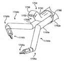
도 17은 제13의 미소절개 수술기구 어셈블리의 형태를 도시하는 개략적인 도면이다.
도 17a는 도 17의 세부사항의 개략적인 측면도이다.
도 17b의 수술기구 어셈블리의 개략적인 투시도이다.
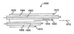
도 18은 제14미소절개 수술기구 어셈블리의 형태를 도시하는 개략적인 도면이다.
도 18a는 기구 어셈블리의 말단 끝부에서의 이미징 시스템의 형태를 도시하는 개략적인 도면이다.
도 18b는 이미징 시스템 이동 형태를 도시하는 개략적인 도면이다.
도 18c는 미소절개 수술기구 어셈블리의 개략적인 투시도이다.
도 18d는 수술기구 어셈블리의 말단 끝부를 피치 업 및 피치 다운하는 방법을 도시하는 개략적인 투시도이다.
도 18e는 미소절개 수술기구 어셈블리의 다른 개략적인 투시도이다.
도 18f는 가이드 튜브의 말단 팁에서 작동가능한 이미징 시스템을 가진 수술기구 어셈블리의 개략적인 평면도이고, 도 18g는 도 18f에 도시된 수술기구 어셈블리의 대안의 형태를 도시하는 세부적인 도면이다.
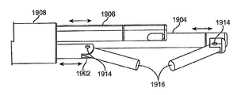
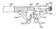
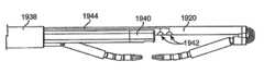
도 19는 제15의 미소절개 수술기구 어셈블리의 형태를 도시하는 개략적인 도면이다.
도 19a는 도 19에 도시된 실시예의 다른 개략적인 투시도이다.
도 19b는 수술기구 어셈블리의 평면도이다.
도 19c는 도 19b에 도시된 수술기구 어셈블리의 다른 평면도이다.
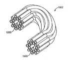
도 19d는 수술기구 메카니즘의 형태를 도시하는 분해 투시도이다.
도 19e는 케이블 가이드 튜브의 투시도이다.
도 19f는 케이블 가이드 튜브의 끝부의 도면이다.
도 19g는 케이블 가이드 피스의 투시도이다.
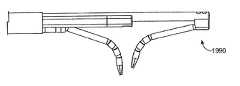
도 19h는 케이블 가이드를 통과하여 빠져나온 수술기구의 형태를 도시하는 투시도이다.
도 19i는 가이드 튜브를 빠져나온 후 수술기구의 모션의 형태를 도시하는 투시도이다.
도 19j는 두 개의 레트로그레이드(retrograde) 수술기구를 가진 수술기구 어셈블리의 형태를 도시하는 투시도이다.
도 19k는 수술기구 어셈블리의 평면도이다.
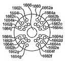
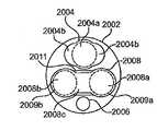
도 20a는 가이드 튜브의 말단 끝면의 도면이다.
도 20b는 이미징 시스템과 수술기구를 가진, 도 20에 도시된 가이드 튜브의 말단 끝면의 도면이다.
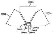
도 20c는 "V"형으로 배열된 홈을 포함하는 수술 채널을 가진 가이드 튜브를 도시하는 끝부의 도면이다.
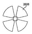
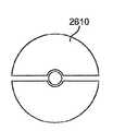
도 20d, 20e, 및 20f는 다른 가이드 튜브 채널 구성을 도시하는 각각의 끝부의 도면이다.
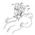
도 21a는 로봇 보조 미소절개 원격수술 시스템의 개략적인 도면이다.
도 21b 및 21c는 원격수술 시스템에서 환자 사이드 지지 시스템의 개략적인 도면이다.
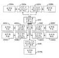
도 22a는 미소절개 원격수술 시스템을 위한 중앙식 모션 제어 시스템의 개략적인 도면이다.
도 22b는 미소절개 원격수술 시스템을 위한 분산식 모션 제어 시스템의 개략적인 도면이다.
도 23은 수술기구 어셈블리와 액츄에이터 어셈블리 사이의 인터페이스의 개략적인 도면이다.
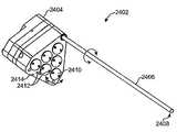
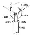
도 24a는 미소절개 수술기구의 근단부의 투시도이다.
도 24b는 도 24a에 도시된 기구와 접하고, 그 기구를 활성화하는 액츄에이터 어셈블리(2420)의 일부분의 투시도이다.
도 25a는 셋업 암의 끝부에서 미소절개 수술기구, 및 액츄에이터 어셈블리를 설치하는 것을 도시하는 개략적인 투시도이다.
도 25b는 셋업 암의 끝부에서 미소절개 수술기구, 및 액츄에이터 어셈블리를 설치하는 것을 도시하는 다른 개략적인 투시도이다.
도 26a는 기구 트랜스미션 메카니즘 및 가이드 튜브의 끝부의 개략적인 도면이다.
도 26b, 26c, 및 26d는 가이드 튜브 둘레에 위치한 트랜스미션 메카니즘의 끝부의 개략적인 도면이다.
도 26e는 액츄에이터 하우징 및 기구의 개략적인 분해투시도이다.
도 27은 플렉시블 동축의 가이드 튜브 및 기구에 연결된 트랜스미션 메카니즘의 개략적인 도면이다.
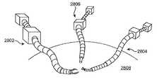
도 28a는 멀티-포트 수술의 한 개략적인 도면이다.
도 28b는 멀티-포트 수술의 다른 개략적인 도면이다.
도 29a 및 29b는 미소절개 수술기구 어셈블리 위치 센싱의 개략적인 도면이다.
도 29c-29e는 조직과의 원치않는 기구 충돌을 방지하는 다른 형태를 도시하는 개략적인 평면도이다.
도 29f는 수술용 이미지 모자이크 출력 디바이스의 개략적인 도면이다.
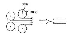
도 30은 미소절개 수술기구의 자동교체 메카니즘의 개략적인 도면이다.
도 30a는 기구 또는 다른 구성요소를 드럼에 저장하는 것의 개략적인 도면이다.
도 30b는 자동 교체가능한 기구를 스풀에 저장하는 것의 개략적인 도면이다.
도 31은 리트랙션을 위해 지정된 다관절형 기구를 포함하는 한 예시적인 미소절개 수술기구 어셈블리의 개략적인 투시도이다.BRIEF DESCRIPTION OF THE DRAWINGS Figure 1 is a schematic representation of the motion of a microcutting surgical instrument and a pivot point represented by an incision or natural opening.
2A is a schematic illustration of another microsurgical instrument and its motion.
2B is a schematic view of another microsurgical instrument and its motion.
Figure 3 is a schematic illustration of a microcutting surgical instrument.
4 is a schematic view showing the shape of the micro incision surgical instrument assembly.
Figures 4a and 4b are schematic perspective views showing the form of a removable mechanism located within the guide tube.
Figure 5 is a schematic view showing the configuration of a second microcutting surgical instrument assembly.
6 is a schematic view showing the configuration of a third microcutting surgical instrument assembly.
7 is a schematic view showing the configuration of a fourth microcutting surgical instrument assembly.
Fig. 8 is a schematic view showing the shape of the fifth micro incision surgical instrument assembly. Fig.
9 is a schematic diagram showing the configuration of a sixth microcutting surgical instrument assembly.
FIG. 9A is a schematic diagram showing the details of the alternative form of FIG.
10 is a schematic view showing the configuration of a seventh microcutting surgical instrument assembly.
11 is a schematic view showing the configuration of the eighth microcutting surgical instrument assembly.
11A and 11B are schematic views of the distal end of the surgical instrument assembly.
12 is a schematic view showing the shape of the ninth incisional surgical instrument assembly;
Figures 12a and 12b are schematic views of the back bent position.
Fig. 13 is a schematic view showing the shape of the tenth microcutting surgical instrument assembly. Fig.
Fig. 14 is a schematic view showing the configuration of the eleventh micro incision surgical instrument assembly. Fig.
Figures 15A-15D are schematic illustrations showing the insertion of a flexible, steerable surgical instrument and a surgical instrument assembly.
16 is a schematic view showing the configuration of the twelfth micro incision surgical instrument assembly.
16A is a side view of one embodiment of the distal end of a microcutting surgical instrument including a parallel motion mechanism.
Figure 16b is a perspective view of one embodiment of a joint within a parallel motion mechanism, and Figure 16c is a cross sectional view thereof.
16D and 16E are schematic diagrams showing the design and operation of the parallel motion mechanism.
Figures 16f and 16g are schematic illustrations of the end of the link disk in a parallel motion mechanism.
Figures 16h and 16i are schematic perspective views of reinforcement brackets in a parallel motion mechanism.
16J is a schematic view of the end portion of the reinforcing bracket.
17 is a schematic diagram showing the configuration of the thirteenth micro incision surgical instrument assembly.
Figure 17a is a schematic side view of the detail of Figure 17;
17B is a schematic perspective view of the surgical instrument assembly of Fig. 17B.
18 is a schematic view showing the shape of the 14th micro incision surgical instrument assembly.
18A is a schematic diagram showing the configuration of the imaging system at the distal end of the instrument assembly.
FIG. 18B is a schematic diagram showing the imaging system movement mode. FIG.
18c is a schematic perspective view of a microcutting surgical instrument assembly.
18D is a schematic perspective view showing a method of pitch-up and pitch-down the distal end of the surgical instrument assembly.
18E is another schematic perspective view of the microcutting surgical instrument assembly.
Figure 18f is a schematic plan view of a surgical instrument assembly having an imaging system operable at the distal tip of the guide tube and Figure 18g is a detail view showing an alternative form of the surgical instrument assembly shown in Figure 18f.
19 is a schematic view showing the shape of the 15th micro incision surgical instrument assembly.
19A is another schematic perspective view of the embodiment shown in FIG.
Figure 19b is a top view of the surgical instrument assembly.
Figure 19c is another plan view of the surgical instrument assembly shown in Figure 19b.
19D is an exploded perspective view showing the configuration of the surgical instrument mechanism.
19E is a perspective view of the cable guide tube.
Figure 19f is a view of the end of the cable guide tube.
19g is a perspective view of the cable guide piece.
19 (h) is a perspective view showing the shape of a surgical instrument that has passed through a cable guide.
Figure 19i is a perspective view showing the shape of the motion of the surgical instrument after exiting the guide tube.
Figure 19j is a perspective view showing the configuration of a surgical instrument assembly with two retrograde surgical instruments.
Figure 19k is a top view of the surgical instrument assembly.
20A is a view of a distal end surface of the guide tube.
20B is a view of a distal end surface of the guide tube shown in Fig. 20 with an imaging system and a surgical instrument.
20C is a view of an end showing a guide tube having a surgical channel including a groove arranged in a "V" shape.
Figures 20d, 20e and 20f are views of the respective ends showing different guide tube channel configurations.
21A is a schematic illustration of a robot assisted microcutting remote surgery system.
Figures 21b and 21c are schematic illustrations of a patient side support system in a remote surgical system.
22A is a schematic diagram of a centralized motion control system for a microcutting remote surgery system.
22B is a schematic diagram of a decentralized motion control system for a microcutting remote surgery system.
23 is a schematic illustration of an interface between a surgical instrument assembly and an actuator assembly.
24A is a perspective view of a proximal end portion of the micro incision surgical instrument.
24B is a perspective view of a portion of an
25A is a schematic perspective view showing the installation of the micro-incision surgical instrument and the actuator assembly at the end of the setup arm.
25B is another schematic perspective view showing the installation of the micro-incision surgical instrument and the actuator assembly at the end of the setup arm.
Figure 26a is a schematic illustration of the mechanism transmission mechanism and the end of the guide tube.
Figures 26b, 26c, and 26d are schematic illustrations of the end of the transmission mechanism located around the guide tube.
Figure 26E is a schematic exploded perspective view of the actuator housing and mechanism.
27 is a schematic illustration of a transmission mechanism coupled to a flexible coaxial guide tube and mechanism.
28A is a schematic illustration of a multi-port operation.
28B is another schematic view of the multi-port operation.
29A and 29B are schematic diagrams of micro-incision surgical instrument assembly position sensing.
Figures 29c-29e are schematic plan views illustrating other forms of preventing unwanted instrument collision with tissue.
29F is a schematic diagram of a surgical image mosaic output device.
30 is a schematic diagram of an automatic replacement mechanism of a microcutting surgical instrument.
30A is a schematic illustration of storing a tool or other component in a drum.
30B is a schematic view of storing a self-replaceable mechanism in a spool.
Figure 31 is a schematic perspective view of an exemplary microcutting surgical instrument assembly including a multi-articulated instrument designated for retraction.
본 발명의 형태 및 실시예를 설명하는 본 설명과 첨부된 도면은 청구항이 정의하는 본 발명의 보호 범위를 제한하지 않는다. 다양한 기계적, 구성적, 구조적, 전기적, 및 동작적 변형이 본 설명 및 청구항의 정신과 범위를 벗어나지 않고 이루어질 수 있다. 몇몇 예에서, 주지된 회로, 구조, 및 기술은 본 발명을 모호하게 하지 않기 위해 상세하게 도시되지 않았다. 둘 이상의 도면에서 유사한 참조번호는 동일하거나 유사한 요소를 나타낸다.This description and the accompanying drawings that illustrate aspects and embodiments of the invention do not limit the scope of protection of the invention as defined by the claims. Various mechanical, structural, structural, electrical, and operational variations may be made without departing from the spirit and scope of the present description and claims. In some instances, well-known circuits, structures, and techniques have not been shown in detail in order not to obscure the present invention. In the drawings, like reference numerals designate the same or similar elements.
또한, 본 설명의 용어는 본 발명을 제한하고자 한 것은 아니다. 예를 들어, "밑에", "아래에", "하부의", 위쪽에", "상부의", "근단의", "말단의" 등과 같은, 공간적으로 상대적인 용어는, 도면에 도시된 바와 같이, 한 요소 또는 피처와 다른 요소 또는 피처의 관계를 설명하기 위해 사용될 수 있다. 이러한 공간적으로 상대적인 용어는 도면에 도시된 위치 및 방향은 물론, 사용중 또는 동작중인 디바이스의 다양한 위치 및 방향을 포함하고자 하였다. 예를 들어, 도면 내의 디바이스가 회전되었다면, 다른 요소 또는 피처 "아래" 또는 "밑"으로 서술된 요소는 그 다른 요소의 "위" 또는 "위쪽에" 있을 수 있다. 그러므로, 예시적인 용어 "아래"는 위쪽 및 아래쪽의 위치 및 방향을 모두 포함할 수 있다. 디바이스는 (90도, 또는 다른 방향으로 회전된) 방향일 수 있고, 본 명세서에 사용된 공간적으로 상대적인 용어는 그에 따라 해석된다. 이와 마찬가지로, 다양한 축을 따른, 또는 축에 대한 이동의 설명은 다양한 특정 디바이스 위치 및 방향을 포함한다. 또한, 단수 형태는 구문에 명시되지 않는다면 복수 형태 또한 포함할 수 있다. 그리고, 용어 "포함한다", "갖추다", "가지다" 등은 언급된 피처, 단계, 동작, 요소, 구성요소, 및/또는 그룹의 존재를 특정하지만, 하나 이상의 다른 피처, 단계, 동작, 요소, 구성요소, 및/또는 그룹의 존재 또는 추가를 배제하지 않는다. 연결된 것으로 서술된 구성요소는 전기적으로 또는 기계적으로 직접 연결될 수 있고, 또는 하나 이상의 매개 구성요소를 통해 간접적으로 연결될 수 있다.In addition, the terminology of the description is not intended to limit the invention. Spatially relative terms such as, for example, "under", "under", "under", "above", "above", "near", "near" Likewise, it should be appreciated that such spatially relative terms may be used to refer to the location and orientation as well as the various positions and orientations of the device in use or during operation, For example, if a device in the drawing is rotated, other elements or features described as "under" or "under" a feature may be "above" or "above" that other element. The "lower" may include both the up and down positions and orientations. The device may be oriented (rotated 90 degrees, or other direction) and the spatially relative terms used herein Similarly, the description of movement along the various axes, or about the axes, includes various specific device positions and orientations. The singular forms may also include plural forms, unless the context clearly dictates otherwise. Steps, operations, elements, components, and / or groups but are not limited to the steps of one or more of the other features, steps, operations, elements, And / or does not exclude the presence or addition of a group. The components described as connected may be electrically or mechanically connected directly or indirectly through one or more intermediate components.
원격조종 등의 용어는 일반적으로 오퍼레이터가 비교적 자연적인 방식(예컨대, 손 또는 손가락의 움직임)으로 마스터 디바이스(예컨대, 입력 운동학적 체인)를 조종하는 것을 의미하고, 여기서 마스터 디바이스 동작은 명령에 그리고 주변 힘에 거의 즉각적으로 반응하는 슬레이브 디바이스(예컨대, 출력 운동학적 체인)로 실시간으로 프로세싱되고 전달되는 명령으로 이루어진다. 원격조종은 미국특허 제6,574,355호('Green')에 개시되어 있다.Remote control, and the like generally means that the operator controls a master device (e.g., an input kinematic chain) in a relatively natural manner (e.g., a movement of a hand or a finger) And a command that is processed and delivered in real time to a slave device (e.g., an output kinematic chain) that reacts almost immediately to force. Remote control is disclosed in U.S. Patent No. 6,574,355 ('Green').
다양한 형태 및 예시적인 실시예의 도면 및 아래의 설명에서 반복을 피하기 위해, 다양한 피처는 다양한 형태 및 실시예에 대하여 공통적임을 이해해야 한다. 본 설명 및 도면에서 한 형태의 생략은 그 형태를 통합한 실시예로부터 그 형태가 빠졌음을 의미하지 않는다. 그 대신에, 그 형태는 명료함을 위해, 그리고 장황한 설명을 피하기 위해 생략될 수 있다.It should be understood that the various features are common to the various forms and embodiments in order to avoid repetition in the various forms and drawings of the exemplary embodiments and the following description. The omission of a form in this description and the drawings does not imply that the form has been omitted from the embodiment incorporating that form. Instead, the form may be omitted for clarity and to avoid redundant explanations.
따라서, 몇가지 일반적인 형태는 아래의 다양한 설명에 적용된다. 예를 들어, 적어도 하나의 수술용 말단 작용기는 다양한 도면에 도시되거나 서술되어 있다. 말단 작용기는 미소절개 수술기구의 일부이거나, 특수한 수술 기능을 수행하는 어셈블리(예컨대, 포셉/그래스퍼, 바늘 구동기, 가위, 전기 후크, 스태플러, 클립 어플라이어/리무버 등)일 수 있다. 다양한 말단 작용기는 단일 DOF를 가질 수 있다(예컨대, 개폐하는 그래스퍼). 말단 작용기는 "손목"형 메카니즘과 같은, 하나 이상의 추가적 DOF를 제공하는 메카니즘과 함께 수술기구 본체에 연결될 수 있다. 이러한 메카니즘의 예는 미국특허 제6,371,952호('Madhani et al.'), 및 미국특허 제6,817,974호('Cooper et al.')에 도시되어 있고, 'da Vinci®Surgical System'을 위한 8mm 및 5mm 기구에 사용된 것과 같은 다양한 'Intuitive Surgical, Inc. Endowrist®mechanism'으로 알려져 있다. 본 명세서에 서술된 수술기구들이 일반적으로 말단 작용기를 포함하고 있으나, 몇몇 형태에서, 말단 작용기는 생략될 수도 있음을 이해해야 한다. 예를 들어, 기구 본체 샤프트의 말단 팁은 조직을 리트랙팅하기 위해 사용될 수 있다. 다른 예로서, 흡입 또는 관개 개구(irrigation opening)가 본체 샤프트, 또는 손목 메카니즘의 말단 팁에 존재할 수 있다. 이러한 형태에서, 말단 작용기의 위치 및 방향의 설명은 말단 작용기를 가지지 않는 수술기구의 팁의 방향 및 위치를 포함함을 이해해야 한다. 예를 들어, 말단 작용기의 팁에 대한 기준 프레임을 다루는 설명은 또한 말단 작용기를 가지지 않은 수술기구의 팁의 기준 프레임을 포함하는 것으로 해석되어야 한다.Thus, some general forms apply to the various descriptions below. For example, at least one surgical end functional group is shown or described in various figures. The terminal functional group may be part of the microsurgical surgical instrument or may be an assembly (e.g., forceps / grasper, needle driver, scissors, electric hook, stapler, clip applicator / remover, etc.) that performs a specific surgical function. The various terminal functional groups may have a single DOF (e.g., opening and closing grasper). The terminal functional group may be connected to the surgical instrument body with a mechanism to provide one or more additional DOF, such as a "wrist" type mechanism. Examples of such mechanisms are shown in U.S. Patent No. 6,371,952 (Madhani et al.), And U.S. Patent No. 6,817,974 ('Cooper et al.'), And 8 mm and 5 mm for the da Vinci®Surgical System A variety of 'Intuitive Surgical, Inc.' Endowrist® mechanism '. It is to be understood that although the surgical instruments described herein generally include a terminal functional group, in some forms, the terminal functional group may be omitted. For example, the distal tip of the instrument body shaft may be used to retract the tissue. As another example, a suction or irrigation opening may be present in the body shaft, or the distal tip of the wrist mechanism. In this form, it should be understood that the description of the position and orientation of the terminal functional group includes the orientation and position of the tip of the surgical instrument without terminal functional groups. For example, the discussion of handling a reference frame for a tip of a terminal functional group should also be interpreted to include a reference frame of a tip of a surgical instrument that does not have a terminal functional group.
본 설명을 통해, 모노-, 또는 입체(stereoscopic) 이미징 시스템/이미지 캡쳐 구성요소/카메라 디바이스는 말단 작용기가 도시되거나 서술된(그 디바이스가 "카메라 기구"로 간주될 수 있는) 기구의 말단 끝부에 위치되거나, 또는 임의의 가이드 튜브 또는 다른 기구 어셈블리 요소의 말단 끝부 또는 그 부근에 설치될 수 있음을 이해해야 한다. 따라서, 용어 본 명세서에서 사용된 "이미징 시스템" 등은 이미지 캡쳐 구성요소, 및 서술된 형태 및 실시예의 환경에서의 이미지 캡쳐 구성요소와 관련 회로의 조합을 모두 포함하기 위해 넓게 해석되어야 한다. 이러한 내시경 이미징 시스템(예컨대, 광, 적외선, 초음파 등)은 떨어져 위치된 이미지 센싱 칩, 및 신체 외부로 유무선 연결을 통해 캡쳐된 이미지 데이터를 전송하는 관련 회로를 포함한다. 이러한 내시경 이미징 시스템은 또한 (예컨대, 로드 렌즈, 또는 광섬유를 사용함으로써) 신체 외부로 캡쳐하기 위한 이미지를 전송하는 시스템을 포함한다. 몇몇 기구, 또는 기구 어셈블리에서, (내시경 이미지가 눈에 직접적으로 보여지는) 다이렉트 뷰 광학 시스템이 사용될 수 있다. 멀리 위치된 반도체 입체 이미징 시스템의 한 예는 미국특허출원 제11/614,661호, "Stereoscopic Endoscope"('Shafer et al.')에 서술되어 있다. 전기적 및 광섬유 조명 커넥션과 같은, 공지된 내시경 이미징 시스템 구성요소는 명료함을 위해 생략되거나 상징적으로 표현된다. 내시경 이미징을 위한 조명은 전형적으로 단일 조명 포트에 의해 도면에 표현된다. 이러한 설명은 예시일 뿐임을 이해해야 한다. 조명 포트의 크기, 위치, 및 개수는 다양할 수 있다. 조명 포트는 전형적으로 음영 깊이를 최소화하기 위해, 이미징 조리개의 복수의 측에 배열되거나, 이미징 조리개를 완전히 둘러싼다.Throughout this description, a mono-or stereoscopic imaging system / image capture component / camera device is described in which a distal end functional group is attached to a distal end of a device (the device may be considered a "camera device" Or may be located at or near the distal end of any guide tube or other instrument assembly element. Thus, the term "imaging system" as used herein should be broadly interpreted to include both an image capture component and a combination of image capture components and associated circuitry in the context of the described aspects and embodiments. Such endoscopic imaging systems (e.g., light, infrared, ultrasound, etc.) include an off-site image sensing chip and associated circuitry for transferring captured image data over a wired or wireless connection to the outside of the body. Such an endoscopic imaging system also includes a system for transferring images for capture outside the body (e.g., by using a rod lens or an optical fiber). In some instruments, or instrument assemblies, a direct view optical system (in which an endoscopic image is seen directly in the eye) may be used. An example of a remotely located semiconductor stereoscopic imaging system is described in U.S. Patent Application No. 11 / 614,661, entitled "Stereoscopic Endoscope" ('Shafer et al.'). Known endoscopic imaging system components, such as electrical and fiber optic illumination connections, are omitted or symbolically represented for clarity. Illumination for endoscopic imaging is typically represented in the drawings by a single illumination port. It should be understood that this description is merely illustrative. The size, location, and number of light ports may vary. The illumination port is typically arranged on the plurality of sides of the imaging diaphragm, or completely surrounding the imaging diaphragm, to minimize shadow depth.
본 설명에서, 캐뉼러(cannula)는 전형적으로 수술기구 또는 가이드 튜브가 환자의 조직을 문지르는 것을 방지하기 위해 사용된다. 캐뉼러는 절개부 및 자연개구부 모두에 대하여 사용될 수 있다. 기구 및 가이드 튜브가 삽입(세로)축에 대하여 빈번하게 이동하거나 회전하지 않는 경우에, 캐뉼러가 사용되지 않을 수 있다. 주입(insufflation)이 필요한 경우에, 캐뉼러는 잉여 주입 가스가 수술기구 또는 가이드 튜브를 지나 새는 것을 방지하기 위한 시일(seal)을 포함할 수 있다. 예를 들어, 주입이 필요하지 않은 흉추(throacic) 수술에 대하여, 캐뉼러 시일은 생략될 수 있고, 기구 또는 가이드 튜브의 삽입축 이동이 적다면, 캐뉼러 자체가 생략될 수도 있다. 강성 가이드 튜브는 가이드 튜브에 대하여 삽입되는 기구에 대한 몇몇 구성에서 캐뉼러로 기능할 수 있다. 캐뉼러 및 가이드 튜브는, 예컨대, 강(steel), 또는 압출된 프라스틱일 수 있다. 강보다 값이 싼 플라스틱은 일회용으로 적합하다.In the present description, a cannula is typically used to prevent the surgical instrument or guide tube from rubbing the tissue of the patient. The cannula may be used for both the incision and the natural opening. In the case where the instrument and the guide tube do not move or rotate frequently with respect to the insertion (longitudinal) axis, the cannula may not be used. If insufflation is required, the cannula may include a seal to prevent surplus injection gas from leaking past the surgical instrument or guide tube. For example, for throacic surgery where implantation is not required, the cannula seal may be omitted and the cannula itself may be omitted if the motion of the insertion shaft of the instrument or guide tube is small. The rigid guide tube may function as a cannula in some configurations for a mechanism to be inserted relative to the guide tube. The cannula and guide tube may be, for example, steel, or extruded plastic. Plastics that are cheaper than steel are suitable for disposable use.
플렉시블 수술기구의 다양한 인스탠스, 및 어셈블리가 도시되고 서술되어 있다. 본 설명에서, 이러한 유연성은 다양한 방법으로 달성된다. 예를 들어, 한 세그먼트, 또는 기구, 또는 가이드 튜브는 헬리컬형으로 감긴 코일, 또는 제거된 다양한 세그먼트(예컨대, 커프(kerf) 타입 컷)를 가진 튜브와 같은, 연속적인 굴곡의 플렉시블 구조일 수 있다. 또는, 플렉시블 부분은 대략 뱀과 같은 연속적으로 굽은 구조를 제공하는 일련의 짧고, 피벗가능하게 연결된 세그먼트("등뼈")로 이루어질 수 있다. 기구 및 가이드 튜브 구조는 미국특허 공개번호 US 2004/0138700 ('Cooper et al.')에 서술되어 있다. 명료함을 위해, 도면 및 관련 설명은 일반적으로 (트랜스미션 메카니즘에 가까운) 근단부, 및 (트랜스미션 메카니즘에서 멀고, 수술 부위에 가까운) 말단부라 하는, 기구와 가이드 튜브의 두 부분만 도시한다. 기구와 가이드 튜브는 세 개 이상의 부분으로 나누어질 수도 있고, 각 부분은 강성, 패시브 플렉시블, 액티브 플렉시블할 수도 있음을 이해해야 한다. 말단부, 근단부, 또는 전체 메카니즘에 대하여 서술된 바와 같은 플렉싱 및 밴딩은 명료함을 위해 생략된 중간 부분에도 적용된다. 예를 들어, 근단부와 및 말단부 사이의 중간부는 단순한 곡선 또는 복합적인 곡선으로 구부러질 수 있다. 플렉시블 부분은 다양한 길이일 수 있다. 더 작은 외경을 가진 부분은 더 큰 외경을 가진 부분보다 밴딩시 더 작은 곡률반경을 가질 것이다. 케이블 제어형 시스템에 대하여, 수용할 수 없는 높은 케이블 마찰, 또는 바인딩은 밴딩시 최소 곡률반경, 및 전체 밴딩 각도를 제한한다. 가이드 튜브의(또는 임의의 관절의) 최고 곡률반경은 그것이 꼬이거나, 내부 수술기구의 메카니즘의 매끄러운 움직임을 방해하지 않도록 하는 반경이다. 플렉시블 구성요소는, 예컨대, 대략 4피트까지의 길이, 및 대략 0.6인치의 직경일 수 있다. 다른 길이 및 직경(예컨대 더 짧거나 더 작은), 및 특정 메카니즘에 대한 유연도는 그 메카니즘이 설계되었던 목표 해부조직에 의해 결정될 수 있다.A variety of in-situ stans and assemblies of flexible surgical instruments are shown and described. In the present description, this flexibility is achieved in various ways. For example, a segment, or instrument, or guide tube may be a continuously curved flexible structure, such as a helically wound coil, or a tube with various segments removed (e.g., a kerf type cut) . Alternatively, the flexible portion may consist of a series of short, pivotably connected segments ("spines") that provide a continuously curved structure, such as a snake. The mechanism and guide tube structure is described in U.S. Patent Publication No.
몇몇 예에서, 기구 또는 가이드 튜브의 말단부만이 플렉시블하고, 근단부는 강성이다. 다른 예에서, 환자 몸속의 기구 또는 가이드 튜브의 전체 부분이 플렉시블이다. 또 다른 예에서, 최말단부는 강성일 수 있고, 하나 이상의 다른 근단부가 플렉시블이다. 플렉시블한 부분은 패시브, 또는 액티브 제어가능(스티어링가능)할 수 있다. 이러한 액티브 제어는, 예컨대, (예컨대, 한 세트는 "피치"를 제어하고, 직교하는 다른 세트는 "요우"를 제어하는) 마주한 케이블 세트를 사용하여 수행될 수 있다. 소형 전자기 액츄에이터, 형상 기억 합금, 전기활성 폴리머("인공 근육"), 기압 또는 공압 벨로우 또는 피스톤 등과 같은 다른 제어 요소가 사용될 수 있다. 기구 또는 가이드 튜브의 한 부분이 다른 가이드 튜브 내부에 완전히 또는 부분적으로 있는 예에서, 패시브 및 액티브 유연성의 다양한 조합이 존재할 수 있다. 예를 들어, 패시브 플렉시블한 가이드 튜브 내의 액티브 플랙시블한 기구는 둘러싼 가이드 튜브를 휘게 하는 충분한 측방향의 힘을 가할 수 있다. 이와 유사하게, 액티브 플렉시블한 가이드 튜브는 내부의 패시브 플렉시블한 기구를 휘게 할 수 있다. 가이드 튜브 및 기구의 액티브 플랙시블한 부분은 협력하여 동작할 수 있다. 플렉시블 및 강성 기구 및 가이드 튜브 모두에 대하여, 중심세로축에서 멀리 떨어진 제어 케이블은 다양한 설계에서 컴플라이언스 고려사항에 따라, 중심세로축에 가깝게 위치된 케이블보다 우수한 기계적인 이점을 제공할 수 있다.In some instances, only the distal end of the instrument or guide tube is flexible and the proximal end is rigid. In another example, the entire portion of the instrument or guide tube in the patient's body is flexible. In yet another example, the distal end can be rigid and at least one other distal end is flexible. The flexible portion can be passive, or can be actively controlled (steerable). This active control can be performed, for example, using opposing cable sets (e.g., one set controls "pitch" and the other set orthogonal controls "yaw"). Other control elements such as small electromagnetic actuators, shape memory alloys, electroactive polymers ("artificial muscles"), pneumatic or pneumatic bellows or pistons, Various combinations of passive and active flexibility may be present in the example where one portion of the instrument or guide tube is completely or partially within the other guide tube. For example, an active flexible instrument in a passive flexible guide tube may apply sufficient lateral force to bend the surrounding guide tube. Similarly, an active flexible guide tube can bend an internal passive flexible mechanism. The active flexible part of the guide tube and instrument can be operated in cooperation. For both flexible and rigid devices and guide tubes, control cables remote from the central longitudinal axis can provide superior mechanical advantages over cables positioned close to the central longitudinal axis, in compliance with compliance considerations in various designs.
플렉시블 부분의 컴플라이언스(뻣뻣함)는 거의 완전히 유연한(작은 내부 마찰이 존재)한 것에서 상당히 강성인 것까지 다양할 수 있다. 몇몇 형태에서, 컴플라이어스는 조절가능하다. 예를 들어, 기구 또는 가이드 튜브의 한 플렉시블 부분 또는 모든 플렉시블 부분은 실질적으로(즉, 유효하나 무한하지는 않은) 강성으로 이루어질 수 있다(그 부분은 "강성 가능" 또는 "잠금 가능"이다). 잠금가능한 부분은 직선으로, 간단한 곡선으로, 또는 복잡한 곡선 형상으로 잠금될 수 있다. 잠금은 인접한 척추로부터 움직임을 막기 위한 마찰을 일으키기 충분한 기구 또는 가이드 튜브를 따라 세로방향으로 이동하는 하나 이상의 케이블에 장력을 제공함으로써 달성될 수 있다. 케이블 또는 케이블들은 각각의 척추의 큰 중앙 홀을 통해 이동하거나, 척추의 바깥 둘레 부근의 작은 홀을 통해 이동할 수 있다. 대안으로서, 하나 이상의 제어 케이블을 움직이기 위한 하나 이상의 구동 모터의 구동 요소가 케이블을 그 위치에 홀딩하기 위해 (예컨대, 서보제어에 의해) 소프트-잠금된 위치일 수 있고, 그로 인해, 기구 또는 가이드 튜브 움직임을 막고, 그러므로, 척추를 그 위치로 잠금한다. 모터 구동 요소를 위치 유지하는 것은 다른 움직임가능한 기구 및 가이드 튜브 구성요소를 효과적으로 위치 유지하기 위해 수행될 수 있다. 서보제어 하에서 단단함은, 유효하더라도, 패시브 셋업 관절을 위치 유지하기 위해 사용되는 브레이크와 같은, 직접적으로 관절에 위치된 브레이크에 의해 얻을 수 있는 뻣뻣함 보다 작은 것이 일반적이다. 케이블의 뻣뻣한 정도는 일반적으로 서보시스템 또는 브레이킹된 관절의 뻣뻣함보다 작기 때문에, 지배하는 것이 일반적이다.The stiffness of the flexible part can vary from almost completely flexible (with small internal friction) to fairly rigid. In some forms, compliance is adjustable. For example, one flexible portion or all flexible portions of a tool or guide tube may be made substantially (i.e., effective but not infinite) in stiffness (the portion is "rigidifiable" or "lockable"). The lockable portion can be locked in a straight line, a simple curve, or a complex curve shape. The locking can be accomplished by providing tension on one or more cables that move longitudinally along a guide tube or a mechanism sufficient to cause friction to prevent movement from the adjacent vertebrae. The cables or cables may move through a large central hole of each vertebra or through a small hole near the periphery of the vertebrae. Alternatively, the drive element of one or more drive motors for moving one or more control cables may be in a soft-locked position (e.g., by servo control) to hold the cable in place, Prevents tube movement, and therefore locks the spine to that position. Positioning the motor-driven element can be performed to effectively position other moveable mechanisms and guide tube components. The rigidity under servo control is generally less than the stiffness obtainable by brakes located directly in the joint, such as the brakes used to hold the passive set joints, even if enabled. The stiffness of the cable is generally less than the stiffness of the servo system or the braked joint, so it is common to dominate.
몇몇 상황에서, 플렉시블 부분의 컴플라이언스는 유연한 상태와 강성 상태 사이에서 연속적으로 변경될 수 있다. 예를 들어, 잠금 케이블 장력은 경도를 증가시키지만 플렉시블 부분을 강성 상태로 잠금하지 않도록 증가될 수 있다. 이러한 중간 컴플라이언스는 수술 부위에 반작용 힘에 의해 발생되는 움직임으로 인해 발생될 수 있는 조직의 외상(trauma)을 줄이면서 원격수술하는 것을 가능하게 할 수 있다. 플렉시블 부분에 통합된 적합한 굽힘 센서는 원격수술 시스템이 기구 및/또는 가이드 튜브 위치를 그것의 밴딩에 따라 판단하는 것을 가능하게 한다. 미국특허출원 공개번호 US2006/0013523('Childers et al.')은 광섬유 위치 형상 센싱 디바이스 및 방법을 개시한다. 미국특허출원 제11/491,384호('Larkin et al.')는 이러한 부분 및 플렉시블 디바이스의 제어에 사용된 광섬유 굽힘 센서(예컨대, 섬유 브라그 격자)을 개시한다.In some situations, the compliance of the flexible portion can be continuously changed between the flexible state and the stiffness state. For example, the locking cable tension may be increased to increase the hardness but not to lock the flexible portion to a rigid state. This intermediate compliance can make it possible to perform a remote operation while reducing the trauma of tissue that can be caused by movement caused by a reaction force on the surgical site. A suitable bending sensor incorporated in the flexible portion enables the remote surgical system to determine the instrument and / or guide tube position according to its banding. United States Patent Application Publication No. US2006 / 0013523 ('Childers et al.') Discloses a fiber optic positional shape sensing device and method. U.S. Patent Application Serial No. 11 / 491,384 ('Larkin et al.') Discloses fiber bending sensors (e.g., fiber Bragg gratings) used in these parts and in the control of flexible devices.
본 명세서에서 서술된 바와 같은 형태의 미소절개 수술기구 어셈블리, 기구, 및 말단 작용기를 제어하기 위한 의사의 입력은 직관적인 카메라 기준의 제어 인터페이스를 사용하여 수행되는 것이 일반적이다. 예를 들어, 'da Vinci®Sugical System'은 이러한 제어 인터페이스를 가진 의사용 컨솔을 포함하고, 본 명세서에 서술된 형태를 제어하도록 조절될 수 있다. 의사는 슬레이브 기구 어셈블리 및 기구를 제어하기 위해, 예컨대, 6개의 DOF를 가진 하나 이상의 마스터 수동 입력 메카니즘을 조종한다. 입력 메카니즘은 하나 이상의 말단 작용기 DOF를 제어하기 위한 손가락으로 작동되는 그래스퍼(예컨대, 클로징 그래스핑 조우)를 포함한다. 말단 작용기와 내시경 이미징 시스템의 상대 위치와, 의사의 입력 메카니즘과 이미지 출력 디스플레이의 위치를 방향 조절함으로써, 직관적인 제어가 제공된다. 이러한 오리엔테이션은 의사가 마치 그 수술 부위를 실제로 참가하여 보고 있는 것처럼 입력 메카니즘과 말단 작용기를 조종하는 것을 가능하게 한다. 이러한 원격오퍼레이션의 실제 프리전스는 의사가 그 수술 부위를 직접 보고 수술하는 오퍼레이터에게 나타나는 화면을 보는 것을 의미한다. 미국특허 제6,671,581호('Niemeyer et al.')는 미소절개 수술장치에서 카메라 기준 제어에 대한 추가 정보를 포함한다.Physician input for controlling the microcutting surgical instrument assembly, instrument, and end functionalities, as described herein, is typically performed using an intuitive camera-based control interface. For example, 'da Vinci®Sugical System' includes a physician console with this control interface and can be adjusted to control the forms described herein. The physician manipulates one or more master passive input mechanisms, e.g., six DOFs, to control the slave mechanism assembly and mechanism. The input mechanism includes a finger-operated grasper (e.g., a closing grasping jaw) for controlling one or more end functionalities DOF. Intuitive control is provided by orienting the relative positions of the end functionalities and the endoscopic imaging system and the position of the physician's input mechanism and the image output display. This orientation makes it possible for the physician to manipulate the input mechanism and end functionalities as if they were actually participating in the surgical site. The actual precession of these remote operations means that the physician sees the surgical site and sees the screen appearing to the operator who is operating. U.S. Patent No. 6,671,581 ('Niemeyer et al.') Includes additional information on camera reference control in the microsurgical surgical device.
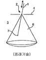
도 1은 미소절개 수술기구(1) 및 그 동작의 개략적인 도면이다. 도 1에 도시된 바와 같이, 수술기구(1)는 신체 캐비티(예컨대, 복강) 또는 내강(3) 내의 작은 절개부(2)를 통해 삽입되는 곧은 강성 기구이다. 절개부(2)는 복부 벽과 같은, 비교적 얇은 신체벽 조직 구조(4)로 이루어진다. 의사는 수동으로(예컨대, 종래의 복강경 기구를 작동 함으로써), 또는 로봇 원격작동에 의해(예컨대, 'Intuitive Surgical, Inc.'의 'da Vinci®Sugical System'을 사용하여) 기구(1)를 작동한다. 기구(1)가 직선형이기 때문에, 기구의 작동은 절개부(2)에 의해 부분적으로 제한된다. 기구(1)는 세로축방향으로 이동(삽입, 또는 퇴진)될 수 있고, 세로축에 대하여 회전될 수 있다. 기구(1)는 또한 볼륨(6)을 통해 말단 작용기(7)를 스위핑하도록, 대략 절개부(2)인 중심점(5)에서 피벗할 수 있다. 기구(1)의 말단 끝부에 (도시되지 않은) 옵션의 손목 메카니즘이 말단 작용기(7)의 방향을 제어하기 위해 사용될 수 있다. 그러나, 몇몇 경우에, 중간 조직 구조(예컨대, 기관 또는 도관, 두꺼운 조직벽(4), 굽은 신체 내강(lumen) 벽 등)가 기구(1)이 절개부(2)에서의 중심점(5)에서 모든 방향 또는 일부의 방향으로 피벗하는 것을 방해하고, 의사가 원하는 수술 부위에 접근하지 못하게 한다.Fig. 1 is a schematic view of the micro incision surgical instrument 1 and its operation. As shown in Fig. 1, the surgical instrument 1 is a straight stiffness mechanism inserted through a body cavity (e. G., Abdominal cavity) or a small incision 2 in the
미소절개 수술기구가 환자에게 삽입된 위치와 수술 부위 사이에서 밴딩되도록 설계되었다면, 중간 조직 구조는 그 기구의 말단 작용기의 포지셔닝을 제한하지 못한다. 이러한 밴딩은 두가지 방식으로 수행될 수 있다. 첫째로, 둘 이상의, 길고 강성 본체부가 하나의 관절에 의해 서로 연결된다. 둘째로, 상술된 바와 같은 플렉시블 메카니즘이 사용된다. 리지드 본체부와 플렉시블 메카니즘의 위치는 기구의 말단 끝부에서 말단 작용기의 위치와 방향에 대하여 액티브 제어된다.If the microsurgical instrument is designed to bend between the inserted position and the surgical site, the intermediate tissue structure does not limit the positioning of the distal end functionalities of the instrument. This banding can be performed in two ways. First, two or more long, rigid body portions are interconnected by a single joint. Secondly, a flexible mechanism as described above is used. The position of the rigid body portion and the flexible mechanism is actively controlled with respect to the position and direction of the terminal functional group at the distal end of the device.
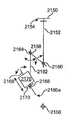
도 2a는 본 발명의 형태에 따른 다른 미소절개 수술기구(10) 및 그 동작의 개략적인 도면이다. 도 2a에 도시된 바와 같이, 기구(10)는 예시적인 근단 기구 본체부(10a), 및 말단 기구 본체부(10b)를 포함한다. 몇몇 형태에서, 둘 이상의 본체부가 사용될 수 있다. 도시된 바와 같이, 근단, 및 말단 본체부(10a, 10b)는 모두 직선형이고 리지드이다. 대안으로서, 본체부(10a, 10b) 중 하나 또는 모두는 특정한 경로 또는 작업을 위한 굴곡을 가질 수 있다. 두 본체부(10a, 10b)는 말단 본체부(10b)가 움직일 수 있게 하는 관절(11)에 연결된다. 몇몇 형태에서, 관절(11)은 본체부(10b)가 본체부(10a)에 대하여 단일 DOF로 움직일 수 있게 하고, 다른 형태에서 관절(11)은 본체부(10b)가 본체부(10a)에 대하여 2 DOF로 움직일 수 있게 한다. 기구(10)는 세로축을 따라 이동(삽입)될 수 있다. 몇몇 형태에서, 근단 본체부(10a)는 세로축에 대하여 회전될 수 있다. 따라서, 말단 본체부(10b)의 말단 끝부에 위치한 말단 작용기(7)는 볼륨(12) 내에 위치될 수 있다. 몇몇 형태에서, 관절(11)은 단일 DOF를 제공하여, 말단 작용기(7)는 근단 본체부(10a)가 그 세로축에 대하여 회전할 때 회전하는 평면 곡선을 따라 스위핑한다. 몇몇 형태에서, 관절(11)은 2 DOF를 제공하여, 말단 작용기(7)는 굴곡진 면을 따라 스위핑한다. 볼륨(12)의 높이는 기구(10)의 삽입 크기에 따른다. 볼륨(12)은 오목한/볼록한 끝을 가진 실린더형으로 도시되어 있다. 기구(10)의 말단 끝부와 관절의 움직임에 따라, 다른 볼륨 형상이 가능하다. 예를 들어, 몇몇 형태에서, 말단 본체부(10b)는 본체부(10a)의 세로축으로부터, 90도 보다 큰 각도, θ로 위치될 수 있다(이러듯 스스로 뒤로 굽는 것을 "레트로플렉티브"라 한다). (도시되지 않은) 옵션의 손목 메카니즘이 말단 작용기(7)의 방향을 변경하기 위해 사용될 수 있다.2A is a schematic diagram of another
도 1에 도시된 기구(1)와 달리, 기구(10)는 관절(11)이 환자 몸속 깊숙이 위치하기 때문에, 환자 벽에서의 피벗에 의해 제한되지 않는다. 그러므로, 기구(10)는 기구(1)의 움직임을 제한하거나(예컨대, 위수술시 식도), 건드리지 말아야할(예컨대, 신경수술시 뇌조직) 중간 조직 구조(13)를 지나 환자 몸속으로 삽입될 수 있다. 따라서, 수술기구(10)의 형태는 의사가 기구(1)를 사용하여 닿을 수 없거나, 수술할 수 없었던 조직에 도달할 수 있게 한다. 수술기구 부분이 직선형이고 리지드이다라는 제약을 제거하면, 조직 구조에 훨씬 우수한 수술 접근성을 제공할 수 있다.Unlike the instrument 1 shown in Fig. 1, the
리지드 기구 본체부만 사용하는 대신에, 하나 이상의 플렉시블 부분이 사용될 수 있다. 도 2b는 본 발명의 형태에 따른 다른 미소절개 수술기구(15) 및 그 동작의 개략적인 도면이다. 도 2b에 도시된 바와 같이, 수술기구(15)는 근단 기구 본체부(15a), 및 말단 기구 본체부(15b)를 가진다. 말단 기구 본체부(15b)는 곧고 강성이지 않고, 상술된 바와 같은 플렉시블하다. 몇몇 실시예에서, 플렉시블 말단 기구 본체부(15b)는 곧은(또는 대안으로써, 굴곡진) 강성 근단 기구 본체부(15a)와 중간 위치(15c)에서 연결된다. 다른 형태에서, 근단 기구 본체부(15a), 및 말단 기구 본체부(15b)는 모두 플렉시블하고, 중간 기구 본체부(15c)는 두 본체부가 결합된 위치를 나타낸다. 말단 기구 본체부(15b)는 간단한 굴곡을 가진 것으로 도시되어 있다. 아래 서술된 바와 같은 다른 형태에서, 본체부(15b)는 2차원 또는 3차원으로 복잡한 굴곡을 가질 수 있다.Instead of using only the rigid tool body portion, one or more flexible portions may be used. Figure 2B is a schematic illustration of another
수술동안, 기구(15)는 도시된 볼륨(16) 내의 다양한 위치에 말단 작용기(7)를 위치시킨다. 기구 본체부(15a)는 중간 조직 구조(13)에 의해 제한되어 있고, 기구 본체부(15b)는 굽어져 있다. 말단 기구 본체부(15b)의 길이 및 곡률반경은 기구(15)가 레트로플렉시블하게 동작할 수 있는지에 따라 결정된다. 기구 본체부(15b)의 복잡한 밴딩은 의사가 볼륨(16)내에서 다른 중간 조직 구조(13a) 주변으로 조종하는 것을 가능하게 할 것임을 알 수 있다(기구(10)(도 2a)가 둘 이상의 말단부를 가진다면, 유사한 동작이 이루어질 수 있다). (도시되지 않은) 옵션의 손목 메카니즘이 말단 작용기(7)의 방향을 제어하기 위해 사용된다. 또한, 몇몇 형태에서, 플렉시블 부분(15b)이 회전을 전달하도록 설계되어 있다면, 말단 작용기(7)는 (손목 메카니즘이 있든 없든) 회전 기구(15)에 의해 회전될 수 있다.During operation, the
도 2a 및 2b에 도시된 수술기구(10 및 15)는 단일 기구로 제한되지 않는다. 기구(10 및 15)로 도시된 아키텍처는 하나 이상의 다양한 가이드 튜브, 수술기구, 및 아래에 서술된 바와 같은 가이드 프루브를 결합한 어셈블리에 적용될 수 있다. 그리고, 하나 이상의 이미징 시스템(내시경)이 이러한 기구 및 기구 어셈블리에 추가될 수 있다. 도면과 연관지어 아래에 서술된 형태는 도 2a 및 도 2b에 일반적으로 도시된 형태의 예이다. 그러므로, 본 발명의 형태는 각각이 서로 독립적으로 동작하고, 각각 한 부모의 단일 엔트리 포트를 통해, 데카르트 공간에서 적어도 6개의 액티브 제어 DOF(즉, 서지, 히브, 스웨이, 롤, 피치, 요우)를 가진 말단 작용기를 갖춘 복수의 원격조종 수술기구를 제공한다. 데카르트 공간에서 말단 작용기의 6개의 DOF는, 예컨대, 또한 수술 부위에 도달하기 위해 그 기구가 통과하는 가이드 튜브를 움직임으로써, 제공되는 DOF에 추가된다.
The
수술기구 어셈블리Surgical Instrument Assembly
도 3은 미소절개 수술기구(300)의 개략적인 도면이다. 수술기구(300)는 전형적으로 캐뉼러(302)를 통해, 또는 자연개구부 또는 절개부를 통해 환자 몸으로 삽입된다. 몇몇 예에서, 수술기구(300)의 본체는 기존의 플렉시블 미소절개 수술기구와 유사한 방식으로 그 전체 길이를 따라 패시브 플렉시블하다. 예를 들어, 케이블은 케이블을 보호하는 외부 시쓰 및 헬리컬하게 감긴 와이어를 통해 축방향으로 이동하고, 케이블은 말단 작용기를 작동하기 위해 코일 내부를 이동한다(예컨대, "보우든(Bowden)" 케이블"). 다른 예로서, 일련의 작은 환형 척추형 세그먼트가 기구(300)를 플렉시블하게 만들기 위해 사용될 수 있다. 다른 예에서, 수술기구(300)의 본체는 근단부(306)와 말단부(308)로 구분될 수 있다. 각각의 기구 본체부(306, 308)는 강성, 패시브 플렉시블, 또는 액티브 플렉시블일 수 있다. 플렉시블 부분은 다양한 직선의 또는 굽은 위치로 ("강성가능" 또는 "잠금가능")일 수 있다. 도 3에 도시된 바와 같이, 예컨대, 근단부(306)는 본질적으로 또는 잠금가능 강성일 수 있고, 말단부(308)는 패시브 또는 액티브 플렉시블일 수 있다. 다른 예에서, 말단부 및 근단부(306, 308)는 모두(본질적으로, 환자의 몸안에 있는 기구(302)의 전체 부분은) 다양한 조합으로 패시브 또는 액티브 플렉시블이고 강성가능할 수 있다.3 is a schematic view of the microsectioning
도 3에 도시된 수술기구(300)는 말단 작용기(304)에 다양한 자유도를 제공한다. 말단 작용기(304)의 위치를 제어하기 위해, 예컨대, 한 조합의 수술기구(300) 삽입 및 말단부(308) 밴딩이 특정된다. 말단 작용기(304)의 방향을 제어하기 위해, 한 조합의 수술기구(300) 회전과 말단부(308) 밴딩이 특정된다. 따라서, 말단부(308)가 (변경 위치(310)로 도시된 바와 같이) 간단한 곡선 내로만 동작될 수 있다면, 4 DOF가 사용가능하다. 말단 작용기(304)의 위치가 특정되면, 말단 작용기(304)의 피치 및 요우는 위치의 함수이다. 말단 작용기(304)의 방향이 특정되면, 히브 및 스웨이의 위치는 방향의 함수이다. 그러므로, 말단 손목 메카니즘이 말단 작용기(304)의 방향을 제어하기 위해 추가되어, 그 위치 및 방향이 특정될 수 있다. 말단부(308)가 (변경 위치(312)로 도시된 바와 같이) 복잡한 굴곡으로 동작될 수 있다면, 6개의 DOF가 사용가능하고, 말단 작용기(304)의 위치 및 방향이 특정될 수 있다. 말단 작용기(304)의 위치 및 방향이 이러한 6 DOF 기구에서 독립적으로 특정될 수 있다 하더라도, 말단 작용기(304)의 오리엔테이션 상에 강화된 제어를 제공하기 위해 말단 손목 메카니즘이 추가될 수도 있다. 이러한 강화된 제어는, 예컨대, 말단부(308)가 취할 수 있는 다양한 포즈에 의해 제공되는 것보다 큰 피치 및 요우 변위, 말단부(308)를 특정 포즈로 유지하는 피치 및 요우 변위, 및 조직이 말단 세그먼트(308)의 포즈 형태를 제한하는 수술 상황에서의 피치 및 요우 변위를 가능하게 한다.The
도 4는 미소절개 수술기구 어셈블리(400)의 예시적인 형태를 도시하는 개략적인 도면이다. 기구 어셈블리(400)는 도 3을 참조하여 서술된 수술기구(300)와 유사한 수술기구(402), 및 가이드 튜브를 포함한다. 가이드 튜브(404)는 근단 끝부(408)에서 말단 끝부(410)까지 연장된, 완전히 또는 부분적으로 인클로징될 수 있는, 적어도 하나의 세로방향의 채널(406)을 가진다. 수술기구(402)는 채널(406)을 통해 움직이고, 예컨대, 가이드 튜브(404) 내에 위치를 유지하기 위한 비회전 소켓에 스냅 피팅될 수 있다. 가이드 튜브(404)는 액티브 제어 메카니즘과 연결된 채널에 부가하여, 예컨대, 관주 또는 흡입이 자신을 통해 수술 부위에 제공될 수 있는 (도시되지 않은) 다른 채널을 가질 수도 있다. 수술기구 어셈블리(400)는 캐뉼러(414)를 통해, 또는 자연개구부 또는 절개부를 통해 하나의 부모에 삽입된다. 몇몇 예에서, 캐뉼러 타입 가이드가 자연개구부를 통한 삽입을 보조하기 위해 사용될 수 있다. 캐뉼러(414) 및 이러한 캐뉼러 타입의 가이드는 (예컨대, 후두부 수술을 위한) 삽입을 용이하게 하기 위해 직선형 또는 곡선형일 수도 있다. 수술기구 어셈블리(400')의 단면은 원형일 수도 있고, 다른 형상(예컨대, 타원형, 둥근 다각형)일 수도 있다. 수술기구(402) 및 가이드 튜브(404)의 다양한 조합은 강성, 패시브 플렉시블, 및 액티브 플렉시블한 것은 물론, 상술한 바와 같은, 가변 컴플라이언스, 및/또는 잠금가능일 수도 있다. 몇몇 예에서, (도시되지 않은) 광 내시경 이미지 시스템이 가이드 튜브(404)의 말단 끝부에 설치될 수 있다.FIG. 4 is a schematic diagram illustrating an exemplary embodiment of a microcutting
몇몇 또는 모든 수술기구(300)(도 3)는 말단 작용기를 다양한 위치 및 방향으로 움직이기 위해 굽혀지는 것과 마찬가지로, 수술기구 어셈블리(400)는 말단 작용기를 다양한 위치 및 방향으로 움직이기 위해 그와 유사하게 굽혀질 수 있다. 수술기구 어셈블리(400)의 말단 끝부(416), 또는 전체 길이는 말단 작용기(412)를 히브 및/또는 스웨이하도록 액티브하게 굽혀질 수 있다. 밴딩과 회전의 조합은 또한 말단 작용기(412)에 사용될 수도 있다. 복잡한 밴딩은 상술된 바와 같은 측방향 이동 동안 말단 작용기(412)가 피치 및/또는 요우잉하는 것을 방지할 수 있다. 변경 위치(418 및 420)는 이러한 액티브 플렉싱을 설명한다. 본 발명의 한 형태에 따라, 몇몇 예에서, 가이드 튜브(404)의 말단 끝부(416)는 말단 작용기(412)에 작은 손목형 피치 및 요우잉 오리엔테이션을 제공한다. 수술기구 어셈블리(400)의 다른 부분은 말단 작용기에 회전 및 위치를 제공한다.As with some or all of the surgical instruments 300 (Fig. 3), as well as being bent to move the end functionalities in various positions and orientations, the
수술기구 어셈블리(400)는 도 3을 참조하여 서술된 바와 같이, 수술기구(300)가 말단 작용기(304)에 제공하는 것보다 말단 작용기(412)에, 일부 리둔던트, 잠재적으로 더 많은 DOF를 제공한다. 도 4에 도시된 바와 같이, 몇몇 형태에서, 말단 작용기(412)가 기구 어셈블리(400)의 세로축 기준으로의 회전으로 변위하되게 하도록, 수술기구(402)가 가이드 튜브(404) 내에서 회전할수 있고, 그리고/또는 가이드 튜브(404)가 캐뉼러(414)(또는 자연개구부)내에서 회전할 수 있다. 말단 작용기(412)가 기구 어셈블리(400)의 세로축을 따라 변위되게 하도록, 기구(402)는 가이드 튜브(404) 내에서 이동할 수 있고, 그리고/또는 가이드 튜브(404)가 캐뉼러(414) 내에서 이동될 수 있다. 대안으로써, 기구(402)는 아래 서술된 바와 같이 가이드 튜브(404) 내에서 그 위치를 유지할 수 있다. 가이드 튜브의 말단 끝부(416)가 수술기구의 말단 끝부(402)에 가하는 측방향의 밴딩 힘은 말단 작용기(412)가 그 수술 작업을 수행할 수 있을 만큼 충분히 강하다. 몇몇 예에서, 말단 작용기(412)는 하나 이상의 추가적인 DOF(예컨대, 롤, 피치, 요우)를 제공하는 손목형 메카니즘을 통해 수술기구(402)의 말단 끝부에 연결될 수 있다.The
도 4는 또한 가이드 튜브가 구부러질 때, 그 굽힘이 그 내부에서 이동하는 기구 또는 다른 가이드 튜브의 오퍼레이션을 방해해서는 안됨을 도시한다. 예를 들어, 가이드 튜브(404)는 말단 작용기(412)를 작동하는 케이블이 마찰로 제한되거나, 영구적으로 꼬여지게 구부러지지 않아야 한다. 몇몇 형태에서, 곡률 반경은, 예컨대, 플렉시블 가이드 튜브를 구성하는 각각의 척추 구조에 의해 기계적으로 제한된다. 다른 형태에서, 곡률반경은, 예컨대, 액츄에이션 동안 더 부드러운 동작을 위해, 아래 서술된 제어 시스템에 의해 제한된다. 또한, 몇몇 형태에서, 내부 기구 및 또는 가이드 튜브용 케이블은 가이드 튜브가 구부러질 때 그들이 제어하는 구성요소가 영향을 받지 않도록 근단 끝부와 말단 끝부 사이보다 더 짧은 경로로 이동해서는 안된다(이러한 시프팅은 말단 굽힘/형상 센서, 및 적절한 케이블 길이를 유지하는 제어 시스템을 사용함으로써 보상될 수 있다). 케이블 경로 길이는 플렉시블 관절의 중심부를 통해 움직이는 케이블에 대하여 시쓰를 사용함으로써(예컨대, '보우든 케이블'), 그리고 가상 피벗 포인트 관절에 대하여 아래에 서술된 바와 같은 관절 둘레를 통해 케이블을 라우팅함으로써 안정화될 수 있다.Fig. 4 also shows that, when the guide tube is bent, its bending must not interfere with the operation of the mechanism or other guide tube moving within it. For example, the
몇몇 예에서, 수술기구(402)는 제거가능할 수 있고, 상이한 수술작업을 수행하기 위해 기구(402)와 유사한 구조를 가졌으나 상이한 말단 작용기를 가진 상이한 수술기구로 교체될 수 있다. 따라서, 하나의 가이드 튜브(404)가 하나 이상의 상호교체가능한 수술기구(402)에 손목형 DOF를 제공하기 위해 사용될 수 있다. 몇몇 예에서, 수술기구는 가이드 튜브(404)가 환자 몸속에 있을 때 상호교체될 수도 있다. 이러한 상호교체는 아래에 더욱 상세하게 서술된다. 가이드 튜브는 그 궤적에 관계없이, 새로 삽입된 기구가 수술 부위에 바로 위치될 수 있게 한다. 그리고, 하나의 가이드 튜브(404)는 완전히 또는 부분적으로 삽입된 수술기구(402)와 함께, 또는 그러한 수술기구 없이 수술 동안 인출되고 다른 튜브로 교체될 수 있다. 몇몇 또는 모든 제어가능한 DOF가 가이드 튜브에 있으므로, 몇몇 형태에서, 기구는 값싸게 만들 수 있으므로, 폐기가능할 수 있고, 가이드 튜브는 살균가능하고 재사용가능하게 만들 수 있다.In some instances, the
도 4a 및 4b는 가이드 튜브(440) 내에 위치 유지된 제거가능한 기구의 형태를 도시하는 개략적인 투시도이다. 가이드 튜브(440)의 말단 끝부(442)는 기구의 말단 끝부가 통과하는 개구(444)를 갖추고 있다. 개구(444)는 옵션으로써 기구가 가이드 튜브(440) 내에서 회전하는 것을 방지하기 위해 비원형으로 만들어질 수 있다. 옵션의 피팅(446)(예컨대, 멈춤쇠(detent) 내로 스냅핑하는 스프링 등)은 기구가 가이드 튜브를 통해 이동하는 것을 방지하기 위해 그 기구의 말단 작용기(448)를 위치 유지한다. 원형 개구(444)는 기구가 회전하는 것을 허용하지만, 피팅(446)이 기구가 이동하는 것을 방지한다. 피팅(446)이 기구를 릴리즈할 때(예컨대, 충분한 인력이 작용된 때), 기구는 가이드 튜브로부터 인출될 수 있다. 말단 끝부(442)는 몇몇 형태의 기구의 말단 작용기를 위한 손목형 메카니즘일 수 있다. 이러한 회전 방지 구성 및 피팅은 가이드 튜브의 말단 끝부에 예시적으로 도시되어 있으나, 다양한 위치(예컨대, 가이드 튜브의 삽입 끝부)에 설치될 수 있다. 회전방지 구성 및 피팅은 다른 기구 및 가이드 튜브 조합을 위해 아래 서술된 다양한 형태로 사용될 수 있고, 회전방지 구성 및 피팅은 리둔던트 삽입 DOF, 및/또는 리둔던트 롤 DOF를 제거할 것임을 이해해야 한다.Figures 4A and 4B are schematic perspective views showing the form of a removable instrument positioned within the
기구 어셈블리(400)는 강성 또는 잠금 상태로 삽입되거나, 목적 수술 부위에 도달하기 위해 삽입동안 액티브하게 스티어링될 수도 있다. 몇몇 형태에서, 기구(402) 및 가이드 튜브(404)는 교대로 동축으로 진행될 수 있다. 예를 들어, 기구(402)는 수술 부위로의 궤적에 따라 부분적으로 스티어링된 후, 잠금된다(기구(또는 가이드 튜브)의 말단부만이 액티브하게 스티어링될 필요가 있고, 보다 더 근단부는 패시브하거나, 그 기구(또는 가이드 튜브)가 진행하는 것과 같은 곡선형 진행을 사용할 수 있다). 곡선형 진행은, 예컨대, 'Ikuta, K. et al.'의 "Shape memory alloy servo actuator system with electric resistance feedback and application for active endoscope"란 제목의, '1998 IEEE International Conference on Robotics and Automation, April 24-29, 1988, Vol.1', 페이지 427-430에 서술되어 있다. 그 다음, 가이드 튜브(404)는 기구(402)의 말단 끝부로 패시브하게 진행되고, 기구(402)의 추가적인 진행을 지원하기 위해 잠금된다. 동축의 교대의 진행, 및 잠금은 원하는 궤적을 따라 수술 부위에 도달할 때까지 계속된다. 대안으로써, 가이드 튜브(404)는 액티브하게 스티어링가능하고 잠금가능하고, 기구(402)는 수술 부위에 도달할 때까지 가이드 튜브 내에서 패시브하게 진행되거나 잠금된다. 기구(402) 및 가이드 튜브(404) 모두 액티브하게 스티어링가능하다면, 그들은 수술 부위로의 궤적을 따라 동축으로 진행하고 잠금될 때, 서로 뛰어넘을(leapfrog) 수 있다. 이러한 동축의 삽입은 본 명세서에 서술된 둘 이상의 기구 및 가이드 튜브의 임의의 조합과 함께 사용될 수 있다.The
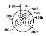
도 5는 제2의 수술기구 어셈블리(500)의 형태를 도시하는 개략적인 도면이다. 수술기구 어셈블리(500)는 둘 이상의 수술기구(502a, 502b)가 하나의 가이드 튜브(504)에 의해 둘러싸일 수 있음을 보여준다. 수술기구(502a, 502b)는 단일 채널(506) 내에서 가이드 튜브(504)를 통해 세로방향으로 이동할 수 있다. 또는, 수술기구(502a, 502b)는 각각의 채널(506a, 506b)을 통해 고유하게 가이드 튜브(504)를 통해 각각 이동할 수 있다. 말단 작용기(508a, 508b)는 수술기구(502a, 502b)의 말단 끝부에 각각 연결된다. 기구 어셈블리(500)는 캐뉼러(510)를 통해 삽입되고, 상술된 바와 동일하다. 기구 어셈블리(500)의 단면은 원형, 타원형, 또는 다른 형상(예컨대, 둥근 사각형 또는 다른 다각형)일 수 있다. 수술기구(502a, 502b)와 가이드 튜브(504)의 다양한 조합은 강성, 패시브 플렉시블, 및 액티브 플렉시블은 물론, 상술된 바와 같은, 잠금가능형일 수 있다. 예시적인 옵션의 이미징 시스템(511)(예컨대, 광학 부재 및 전자기기에 연결된 하나 이상의 이미지 캡쳐 칩)이 가이드 튜브(504)의 말단 끝부에 설치된다. 이미징 시스템(511)은 가이드 튜브(504)의 진행을 돕기 위해 사용될 수 있고, 의사가 수술 부위에서 작동하는 말단 작용기(508a, 508b)를 볼 수 있게 하는 시야를 가진다.FIG. 5 is a schematic diagram illustrating the configuration of a second
수술기구 어셈블리(500)는 둘 이상의 수술기구가 근단 끝부에서 말단 끝부로 하나의 가이드 튜브를 통해 연장되어 있다는 점을 제외하면, 수술기구 어셈블리(400)(도 4)와 유사한 방식으로 동작한다. 따라서, 추가적인 채널, 액티브 및 패시브 유연성, 잠금/강성화, 다양한 DOF, 손목형 메카니즘의 옵션의 사용, 기구 상호교체가능성, 교대의 동축 진행, 및 캐뉼러의 상술된 설명은 기구 어셈블리(500)에도 적용된다. 말단 끝부 및 전체 어셈블리의 유연성은 상술된 바와 같이 앞선 도면에 도시된 것과 유사한, 위치 변경선(512 및 514)에 의해 보여진다. 가이드 튜브(504)의 복잡한 밴딩은 상술된 바와 같이, 말단 작용기(508a, 508b)에 적어도 6개의 DOF를 제공한다. 교대의 동축 진행은 상술된 바와 같이 이루어진다. 이러한 진행은 다양한 방식이 가능하다. 예를 들어, 몇몇 형태에서, 두 기구 모두 사용될 수 있고, 가이드 튜브가 두 기구 상으로 미끄러질 수 있고; 다른 형태에서, 제1기구가 진행되고 잠금된 후, 가이드 튜브가 진행되고 잠금되고, 그 후 다른 기구가 진행되고 잠금되는 식이다.The
도 6은 제3의 미소절개 수술기구 어셈블리(600)의 형태를 도시하는 개략적인 도면이다. 수술기구 어셈블리(600)는 수술기구(602)의 액티브하게 플렉시블한 말단부(604)가 가이드 튜브(606)의 말단 끝부 아래로 연장된 점을 제외하면, 기구 어셈블리(400)(도 4)와 유사한 방식으로 동작한다. 가이드 튜브(606)의 말단 끝부(608), 및 또는 가이드 튜브(606)의 액티브 유연성은 위치 변경선(610, 및 612)에 의해 보여진다. 기구(602)의 말단부(604)의 액티브 유연성은 말단 작용기(614)를 도시된 변경 위치(616)로 이동시킨다. 따라서, 말단 작용기(614)는 기구(602)의 말단부(604)의 이동으로부터, 가이드 튜브(606)의 말단 끝부(608)의 이동으로부터, 그리고/또는 말단부(604, 608)에 의한 이동의 조합으로 부터 손목형 DOF(예컨대, 롤, 피치, 요우)를 경험한다. 그러므로, 기구 어셈블리(600)는 기구와 가이드의 조합이 말단 작용기(614)에 리둔던트 위치 및 방향 DOF를 제공하는 형태를 보여준다. 추가적인 채널, 액티브 및 패시브 유연성, 잠금/강성화, 다양한 자유도, 향상된 측방향 힘 적용 및 경도, 손목형 메카니즘 및 이미징 시스템의 옵션의 사용, 기구 상호교체가능성, 교대의 동축 진행, 및 캐뉼러는 기구 어셈블리(600)에도 적용된다.FIG. 6 is a schematic diagram illustrating the configuration of a third microcutting
도 7은 제4의 미소절개 수술기구 어셈블리(700)의 형태를 도시하는 개략적인 도면이다. 도 7에 도시된 바와 같이, 기구(702)는 기구 어셈블리(700)의 세로축을 따라 1차 가이드 튜브(704)를 통해 연장되어 있다. 또한, 1차 가이드 튜브(704)는 세로축을 따라 2차 가이드 튜브(706)를 통해 연장되어 있다. 몇몇 예에서, 수술기구 어셈블리(700)는 캐뉼러(708)를 통해 삽입된다. 말단 작용기(710)는 수술기구(702)의 말단 끝부에 연결되어, 말단 작용기(710)는 1차 가이드 튜브(704)의 말단 끝부를 지나 연장된다.FIG. 7 is a schematic diagram illustrating the configuration of a fourth microcutting
특정 동작(예컨대, 그립핑)과 연관된 고유한 하나 이상의 DOF 외의, 말단 작용기(710)의 리둔던트 DOF는 다양한 방법으로 제공된다. 수술기구(702)는 1차 가이드 튜브(704) 내에서 회전할 수 있고, 그리고/또는 1차 가이드 튜브(704)는 2차 가이드 튜브(706) 내에서 회전될 수 있고, 2차 가이드 튜브(706)는 캐뉼러(708)(또는 자연개구부 또는 절개부)에서 회전될 수 있고, 이는 말단 작용기(710)가 기구 어셈블리(700)의 세로축에 대하여 회전 이동되게 한다. 수술기구(702)는기구 어셈블리(700)의 세로축을 따라 말단 작용기(710)를 변위(서지)시키기 위해 1차 가이드 튜브(704) 내에서 이동할 수 있고, 그리고/또는 1차 가이드 튜브(704)는 2차 가이드 튜브(706) 내에서 이동할 수 있고, 그리고/또는 2차 가이드 튜브(706)는 캐뉼러(708) 내에서 이동할 수 있다.Other than the inherent one or more DOFs associated with a particular operation (e.g., gripping), the rearward DOF of the
도 7에 도시된 바와 같이, 1차 가이드 튜브(704)의 액티브하게 플렉시블한 말단부(712)는 2차 가이드 튜브(706)의 말단 끝부를 지나 연장되어있다. 말단부(712)는 말단 작용기(710)가 (상술된 바와 같은 부수적인 피치 및 요우와 함께) 위브 및/또는 스웨이하게 할 수 있고, 변경 위치(714)로 도시된 바와 같이, 하나 또는 둘 이상의 추가적인 자유도를 더한다. 이와 유사하게, 2차 가이드 튜브(706)의 액티브하게 플렉시블한 말단부(716), 또는 전체 2차 가이드 튜브(706)는 말단 작용기(710)가 위브 및/또는 스웨이하게 할 수 있고, 변겨 위치(718, 및 720)로 도시된 바와 같이 하나 또는 둘 이상의 자유도를 더한다. 기구 어셈블리(700)가 말단 작용기(710)에 다양한 조합의 롤, 위브 및 스웨이 변위를 제공하므로, 손목형 메카니즘이 말단 작용기(710)를 수술기구(702)에 연결하기 위해 필요하지 않을 수도 있으나, 이러한 메카니즘은 추가적인 하나 이상의 자유도(예컨대, 롤, 피치, 요우)를 제공하기 위해 사용될 수도 있다.7, the actively flexible
도 7의 변경 위치에 의해 알 수 있는 바와 같이, 1차 및 2차 가이드 튜브는 다양한 조합의 간단한 밴딩 및 복잡한 밴딩과 함께 말단 작용기(710)를 조종할 수 있다. 한 예시적인 실시예에서, 2차 가이드 튜브(706)의 액티브 유연성은 말단 작용기(710)의 비교적 큰 움직임을 위해 사용되고, 1차 가이드 튜브의 말단부(712)의 액티브 유연성은 말단 작용기(710)의 비교적 작은 손목 타입의 동작을 위해 사용된다. 이러한 모션의 크기는 말단부(712)가 2차 가이드 튜브(706)를 지나 연장된 거리에 따르므로, 도 2b에 서술된 동작과 유사한 동작을 제공할 수 있다.As can be seen by the altered position of Figure 7, the primary and secondary guide tubes can steer the
몇몇 예에서, 수술기구(702)는 도 6에 서술된 바와 같이 1차 가이드 튜브(704)를 지나 연장될 수 있다. 추가적인 채널, 액티브 및 패시브 유연성, 잠금/강성화, 다양한 DOF, 향상된 측방향 힘 적용 및 경도, 기구 상호교체가능성, 교대의 동축 진행, 및 캐뉼러의 상술된 설명은 기구 어셈블리(700)에도 적용된다. 또한, 2차 가이드 튜브(706)는 1차 가이드 튜브(704)보다 훨씬 더 큰 외경을 가지기 때문에, 2차 가이드 튜브(706)를 위한 액츄에이션 및 잠금 메카니즘은 기구(702) 또는 1차 가이드 튜브(704) 중 하나가 단독으로 또는 함께 제공할 수 있는 반작용력 보다 증가된 측방향 힘 및 경도를 제공할 수 있다.In some instances, the
도 8은 제5의 미소절개 수술기구 어셈블리(800)의 형태를 도시하는 개략적인 도면이다. 수술기구 어셈블리(800)는 둘 이상의 1차 가이드 튜브(802a, 802b)가 하나의 2차 가이드 튜브(804)에 의해 둘러싸일 수 있음을 보여준다. 예시적인 수술기구(806a, 806b)는 각각의 1차 가이드 튜브(802a, 802b)를 통해 이동한다. 1차 가이드 튜브(802a, 802b)는 기구 어셈블리(400)(도 4)와 일반적으로 유사한 아키텍처를 가진다. 그러나, 몇몇 예에서, 하나 이상의 1차 가이드 튜브(802)는 수술기구 어셈블리(500)(도 5), 또는 수술기구 어셈블리(600)(도 6)와 유사한 아키텍처를 가질 수도 있다. 2차 가이드 튜브(804)의 말단 끝부를 지나 연장되어 있는 1차 가이드 튜브(802a, 802b)의 말단부의 액티브 유연성은 위치 변경선(808a, 808b)에 의해 도시되어 있다. 1차 가이드 튜브(802a, 802b)의 말단부는 다양한 수술동작을 실시하기 위해 환자 몸속의 수술 부위의 다양한 위치로 서로 인접한 말단 작용기(809a, 809b)를 이동시킬 수 있다. 2차 가이드 튜브(804)의 다양한 액티브 유연성은 위치 변경선(810a, 810b)에 의해 도시되어 있다. 추가적인 채널, 액티브 및 패시브 유연성, 잠금/강성화, 다양한 DOF, 향상된 측방향 힘 적용 및 경도, 손목형 메카니즘의 옵션의 사용, 교대의 동축 진행, 및 캐뉼러의 상기 설명은 기구 어셈블리(800)에도 적용된다.FIG. 8 is a schematic diagram illustrating the configuration of a fifth microcutting
몇몇 예에서, 점선 박스로 개략적으로 표시된, 내시경 이미징 시스템(812)이 2차 가이드 튜브(804)의 말단 끝부에 위치될 수 있다. 이미징 시스템(812)은 상술된 바와 같이, 모노- 또는 입체 일 수 있고, 기구 어셈블리(800)의 세로축과 나란한 각도, 또는 일정한 각도(예컨대, 30도)의 시야를 가질 수 있다. 몇몇 예에서, 이미징 시스템(812)은 1차 가이드 튜브(802a, 802b) 사이에 위치된다. 다른 예에서, 이미징 시스템(812)은 2차 가이드 튜브(804)의 단면을 보다 컴팩트하게 만들기 위해 1차 가이드 튜브(802a, 802b)의 위, 아래, 또는 측면에 위치될 수 있다(예컨대, 하나의 입체 렌즈는 1차 가이드 튜브(802a, 802b) 위에 , 다른 렌즈는 그 아래에; 이러한 구성을 위해, 카메라 기준 제어는 가이드 튜브가 밖으로 굽은 후, 인터푸필러리 축(interpupillary axis)과 대략적으로 동일한 평면인 수술 부위를 향해 안으로 굽을 때 이루어질수 있다).In some instances, an
도 9는 제6의 미소절개 수술기구 어셈블리(900)의 형태를 도시하는 개략적인 도면이다. 기구 어셈블리(900)는 예시적인 추가 수술기구(902)가 2차 가이드 튜브(904)를 통해 연장되어 있으나, 수술기구(902)가 1차 가이드 튜브에 의해 둘러싸이지 않은 점을 제외하면, 기구 어셈블리(800)(도 8)와 유사하다. 따라서, 수술기구(902)와 2차 가이드 튜브(904) 간의 관계는 도 4, 및 6에 도시된 바와 같이 수술기구와 가이드 튜브 간의 관계와 유사하다. 1차 가이드 튜브(906a, 906b)와 기구(908a, 908b) 어셈블리 사이의 관계는 도 7과 8에 도시된 형태에 대하여 서술된 관계와 유사하다. 기구 어셈블리(900)는 하나 이상의 1차 가이드 튜브와 기구 어셈블리의 다양한 조합을 통해 연장된 2차 가이드 튜브는 물론, 가이드 튜브없는 하나 이상의 기구를 설명한다.FIG. 9 is a schematic diagram illustrating the configuration of a sixth microcutting
몇몇 예에서, 수술기구(902)는 강성, 또는 패시브 플렉시블하고, 그 말단 작용기(910)는 기구(908a, 908b) 끝부의 말단 작용기(912a, 912b)가 수행하는 수술 동작을 돕기 위해 조직을 잡거나 당기기 위해 사용된다. 강성 또는 패시브 플렉시블이더라도, 기구(902)는 상당한 힘으로 당길 수 있다. 다른 예에서, 수술기구는 레트렉션, 관주, 흡입 등과 같은 다른 기능을 수행할 수도 있다. 또한, 기구 어셈블리(800)(도 8)에 의해 도시된 바와 같이, 내시경 이미징 시스템이 2차 가이드 튜브(904)의 말단 끝부에 설치되었다면, 기구(902)는 이미징 시스템의 윈도우를 서비스(예컨대, 유체 분사 세척)하기 위해 사용될 수 있다.In some instances, the
또 다른 예에서, 상술된 바와 같이, 수술기구(902)의 말단 끝부는 액티브 플렉시블하고, 말단 작용기(910)는 도 9a에 도시된 바와 같이, 내시경 이미징 시스템(914)으로 교체될 수 있다. 이러한 예에서, 말단 이미징 디바이스는 적어도 하나의 DOF를 피치로 제공하는 손목 타입 메카니즘(916)을 가진 수술기구(902)의 액티브 플렉시블한 끝부에 연결될 수 있다. 이러한 아키텍처는 이미징 센싱 디바이스가 1차 가이드 튜브(906a, 906b)의 말단 끝부 사이에서 벗어나는 것을 가능하게 하고, 말단 작용기(912a, 912b)가 동작하는 영역을 가진 시야의 중심과 나란하도록 시야각이 피칭된다(그리고/또는 요잉된다). 이러한 아키텍처는 두개의 독립된 액츄에이팅되는 수술 말단 작용기, 및 수술기구와 독립된 내시경 이미징 시스템과 함께, 몸 속으로 하나의 단일 입구 포트를 통해 수술 부위에서, 의사가 수술하는 것을 가능하게 한다. 도 9a에 도시된 독립적으로 제어되는 이미징 시스템의 다른 장점은 아래의 도 17a를 참조하여 더 상세하게 서술되고 도시된 바와 같은, 조직 리트랙션이다.In another example, as discussed above, the distal end of the
상술된 형태에 따라, 하나 이상의 수술기구는 평평한 면이거나, 다른 형상일 수 있고, 어셈블리의 세로축에 대하여 정방형이거나 기울어질 수 있는 가이드 튜브의 말단 끝부에서 빠져나간다. 다른 형태에 따라, 하나 이상의 수술기구는 가이드 튜브의 측면에서 빠져나간다. 도 10은 제7의 미소절개 수술 어셈블리(1000)의 이러한 형태를 도시하는 개략적인 도면이다.According to the above-described form, the at least one surgical instrument may be a flat surface or other shape, and may extend out of the distal end of the guide tube, which may be square or tiltable with respect to the longitudinal axis of the assembly. According to another aspect, the at least one surgical instrument exits the side of the guide tube. FIG. 10 is a schematic view showing this form of the seventh microcutting
도 10에 도시된 바와 같이, (둘 이상의 기구의 예로서) 두 개의 수술기구(1002a, 1002b)는 가이드 튜브(1004)의 최말단 끝부 대신에, 측면 출구(1008a, 1008b)를 통해 가이드 튜브(1004)의 말단부(1006)를 빠져나간다. 측면 출구(1008a, 1008b)는 일반적으로 서로 마주보는 방향(즉, 대략 서로 180도 떨어진)일 수 있고, 또는 더 작은 각(예컨대, 120도)만큼 떨어질 수 있다. 그리고, 측면 출구는 둘 이상의 출구가 하나, 둘, 또는 둘 이상의 기구(1002)를 위해 사용된 형태에서 말단부(1006) 둘레에 다양한 각의 방향을 가질 수 있다. 한 형태에서, 하나의 측면 출구는 가이드 튜브(1004)의 말단 팁에서부터 다른 측면 출구 보다 더 멀리 떨어져 있다. 기구(1002a)의 말단부(1010a) 및 기구(1002b)의 말단부(1010b)는 수술 부위에서 수술을 위해 말단 작용기(1012a, 1012b)를 움직이기 위해 각각 독립적으로 액티브 플렉시블하다. 옵션의 손목 메카니즘과 함께, 기기 회전 및 삽입과 간단하거나 복합한 밴딩의 다양한 조합은 요구되는 말단 작용기 DOF를 제공한다. 내시경 이미징 시스템(1014)은 가이드 튜브(1004)의 말단 끝부에 위치된다. 이미징 시스템(1014)의 시야각은 기구 어셈블리(1000)의 세로축과 일치되거나, 시야각은 세로축으로부터 (예컨대, 30도로) 기울어질 수 있다. 몇몇 형태에서, 시야각은, 예컨대, 하나 이상의 동작가능한 반사면(미러, 프리즘)을 사용하여, 수술 과정 프로시저 동안 액티브하게 변경될 수 있다. 추가적인 채널, 액티브 및 패시브 유연성, 잠금/강성화, 다양한 DOF, 향상된 측방향 힘 적용 및 경도, 손목형 메카니즘의 옵션의 사용, 기구 상호교체가능성, 및 캐뉼러의 상기 설명은 기구 어셈블리(1000)에도 적용된다.10, two
수술 어셈블리(1000)는, 몇몇 예에서, 캐뉼러(1016) 또는 상술된 바와 유사한 가이딩 구조를 통해 절개부 또는 자연개구부를 통해 환자 몸속으로 삽입된다. 가이드 튜브(1004)가 삽입된 때, 몇몇 예에서, 수술기구(1002a, 1002b)는 가이드 튜브(1004)가 수술 부위를 향해 진행할 때, 개구부(1008a, 1008b)를 넘어 연장되지지 않도록, 완전히 또는 부분적으로 리트랙팅한다. 이미징 시스템(1014)으로부터의 이미지가 진행을 도울 수 있다. 가이드 튜브(1004)가 수술 부위의 제위치에 도달하면, 기구(1002a, 1002b)가 수술 부위에 도달하기 위해 가이드 튜브(1004) 내로 삽입되고, 그리고/또는 진행할 수 있다. 가이드 튜브(1004)는 수술 부위에서 큰 움직임을 제공하기 위해 수술 진행동안 액티브하게 굽혀질 수 있고, 기구 말단부(1010a, 1010b)는 위치 변경선(1012a, 1012b)에 의해 도시된, 수술 동작을 완성하기 위해 미세한 움직임을 실행한다. 의사는 말단 작용기(1012a, 1012b)로 수술 작업을 수행하면서, 이미징 시스템(1014)으로부터의 이미지를 본다. 의사는 그들이 측면 출구(1008a, 1008b)를 빠져나갈 때, 말단부(1010a, 1010b)의 이미징 시스템(1014)으로부터 이미지를 볼 수 없기 때문에, 아래 서술된, 몇몇 형태의 제어 시스템에서, 가이드 튜브(1004)로부터 빠져나갈 때, 가이드 튜브가 이미징 시스템(1014)의 앞부분에 맞게 굽도록 말단부(1010a, 1010b)를 제어한다. 다른 형태에서, 내강 공간이 아래 서술된 바와 같이 맵핑되고, 제어 시스템은 말단 작용기를 이미징 시스템(1014)의 시야 내로 가이드하기 위해 맵핑 데이터를 사용한다. 또 다른 형태에서, 가이드 튜브의 말단부는 예컨대, 알고 있는 공간으로부터 왼쪽으로 이동될 수 있고, 그로 인해, 우측 기구가 우측의 가이드 튜브에 "안전" 공간으로 삽입되는 것을 가능하게 한다. 그 다음, 이와 마찬가지로, 가이드 튜브의 말단 끝부는 우측으로 이동되고, 좌측 기구가 좌측의 가이드 튜브에 대한 "안전 공간"으로 이동된다. 가이드 튜브의 말단 끝부가 기구가 빠져나가는 가이드 튜브의 부분에 관계없이 위로 움직이는 형태에 대하여, 기구는 가이드 튜브의 위로 변위된 말단 끝부 바로 아래의 "안전" 공간으로 유사하게 삽입될 수 있다. 인출, 또는 후속의 큰 리포지셔닝을 위해, 기구(1002a, 1002b)는 가이드 튜브(1004)로부터 완전히 또는 부분적으로 측면 출구(1008a, 1008b)를 통해 인출될 수 있다.The
도 11은 제8의 미소절개 수술기구 어셈블리(1100)의 형태를 도시하는 개략적인 도면이다. 도 11에 도시된 바와 같이, 수술기구(1102a)는 그 세로축을 따라 1차 가이드 튜브(1104a)를 통해 연장되어 있다. 이와 마찬가지로, 수술기구(1102b)는 그 세로축을 따라 1차 가이드 튜브(1104b)를 통해 연장되어 있다. 말단 작용기(1106a, 1106b)는 기구(1102a, 1102b)의 말단 끝부에 연결되어 있다. 1차 가이드 튜브(1104, 1104b)는 2차 가이드 튜브(1108)를 통해 세로로 연장되어 있다. 수술기구(1102a, 1102b)가 가이드 튜브(1104)의 말단부(1106)의 측면 출구(1008a, 1008b)를 빠져나가는 방식과 유사한 방식으로, 1차 가이드 튜브(1104a, 1104b)는 2차 가이드 튜브(1108)의 측면 출구(1110a, 1110b)를 빠져나간다. 1차 가이드 튜브(1104a, 1104b)의 말단부(1112a, 1112b)는 위치 변경선(1114a, 1114b)에 의해 도시된 바와 같이, 말단 작용기(1106a, 1106b)를 움직이기 위해 액티브하게 굽혀진다. 내시경 이미징 시스템(1116)은 2차 가이드 튜브(1108)의 말단 끝부에 위치된다. 추가적인 채널, 액티브 및 패시브 유연성, 잠금/강성화, 다양한 DOF, 향상된 측방향 힘 적용 및 경도, 손목형 메카니즘의 옵션의 사용, 기구 상호교체가능성, 및 캐뉼러의 상기 설명은 기구 어셈블리(1100)에도 적용된다.11 is a schematic diagram showing the configuration of the eighth microcutting
기구 어셈블리(1100)는 기구 어셈블리(1000)(도 10)와 유사한 방식으로 동작한다. 두 형태 사이의 주된 차이점은 어셈블리(1100)에서 2차 가이드 튜브와 1차 가이드 튜브를 모두 사용한다는 것이다. 그러므로, 기구 어셈블리(1100 및 1000) 사이의 관계는 기구 어셈블리(800)(도 8)와 기구 어셈블리(500)(도 5) 사이의 관계와 유사하다. 삽입, 삽입 및 리포지셔닝 동안 완전히 또는 부분적인 기구 리트랙션, 이미징 시스템의 사용, 1차 가이드 튜브 및 2차 가이드 튜브의 사용, 및 기구의 제어된 연장의 상기 설명은 기구 어셈블리(1100)의 형태에도 적용된다.
도 11a 및 11b는 수술기구 어셈블리의 끝부의 개략적인 도면이고, 어셈블리(1000)(도 10), 및 1100(도 11))와 같은, 측면 출구 어셈블리가 가이드 튜브 또는 2차 가이드 튜브의 전체 단면적을 줄이기 위해 사용될 수 있음을 도시한다. 도 11a는 기구/가이드 튜브 조합(802a, 806a, 및 802b, 806b)이 가이드 튜브 또는 2차 가이드 튜브의 말단 끝부로부터 빠져나가는, (원형의 단면 형상만 도시된) 어셈블리(800)와 같은, 어셈블리의 개략적인 도면이다. 본 예에서, 이미징 시스템(812)은 이미징 포트와 도시된 조명 포트(1122) 사이의 인터푸필러리 디스턴스(interpupillary distance)를 가진 입체 이미징 시스템이다. 도 11b의 예에 도시된 바와 같이, 측면 출구 어셈블리의 기구/말단 가이드 튜브부 조합(1102a, 1112a 및 1102b, 1112b)은 도 11a에 도시된 조합(802a, 806a, 및 802b, 806b)과 동일한 단면적을 가진다. 그리고, 예시의 입체 이미징 시스템(1116)은 도 11a에 도시된 이미징 시스템(812)과 동일한 인터푸필러리 디스턴스를 가진다. 내시경 이미지가 가이드 튜브의 말단 끝부에서 캡쳐되고 디지털화되면, 가이드 튜브 영역 부근의 이미징 캡쳐 및 디지털화 구성요소가 광학 부재(예컨대, 광섬유 다발, 로드 렌즈 등)를 대신하여 기구 및 액츄에이션을 위해 사용될 수 있다. 결과적으로, 도 11b의 측면 출구 가이드 튜브의 타원형 단면적은 도 11a의 측면 출구 가이드 튜브의 단면적보다 작고, 이미징 시스템의 인터푸필러리 디스턴스는 동일하다. 이러한 감소된 단면적은, 예컨대, 특정의 자연개구부의 크기에 대하여, 삽입 포트와 수술 부위 사이의 중간 조직의 위치에 대하여, 사용되어야 하는 절개부의 크기 및 위치에 대한 장점일 수 있다. 이러한 타원형 단면 형상은 본 명세서에 서술된 다른 기구 어셈블리 가이드 튜브에 사용될 수 있다.Figures 11a and 11b are schematic illustrations of the end of a surgical instrument assembly, wherein the side exit assembly, such as assembly 1000 (Figure 10), and 1100 (Figure 11) ≪ / RTI > Figure 11a illustrates an
도 12는 제9의 미소절개 수술기구 어셈블리(1200)의 형태를 도시하는 개략적인 도면이다. 기구 어셈블리(1200)는 2차 가이드 튜브(1204)의 말단 끝부로부터 연장된 추가적인 수술기구(1202)를 가지고, 기구 어셈블리(1100)와 유사하다. 수술기구(1202)는 수술기구(902)(도 9)와 유사한 방식으로 작동하고, 몇몇 형태에서, 강성이고, 다른 형태에서 상술한 바와 같이 패시브 또는 액티브 플렉시블하다. 그리고, 말단 작용기(1206)는 도 9 및 9a, 또는 도 17 및 17a에 관하여 서술된 바와 같은 내시경 이미징 시스템으로 교체될 수 있고, 그러므로 몇몇 형태에서, 기구 어셈블리(1200)는 도 12에 도시된 바와 같은, 독립적으로 작동되는, 옵션의 손목-마운팅된 내시경 이미징 시스템(1208)을 가진다.12 is a schematic diagram showing the configuration of the ninth incisional
도 12a, 및 12b는 상술된 말단-출구 가이드 튜브를 위한 레트로플렉시브 동작과 유사한, 측면 출구 가이드 튜브의 예에서의 레트로플렉시브 위치를 보여주는 실시예의 개략적인 도면이다. 도 12a는, 한 형태에서, 측면 출구 기구 어셈블리(1220)가 측면 출구(1222a, 및 1222b)와 대략 동일한 평면인 평면에서 액티브하게 굽혀짐을 도시한다. 도 12b는, 다른 형태에서, 측면 출구 기구 어셈블리(1230)가 측면 출구(1232a, 및 1232b)에 대략 수직인 (도시되지 않은) 평면에서 액티브하게 굽혀짐을 도시한다(시야 기준을 참조하면 피칭한다). 어셈블리(1230)의 곡률반경은 어셈블리(1220)의 곡률반경보다 작을 수 있고, 그 기계적 구조로 인한 다른 치수는 실질적으로 동일하다. 몇몇 형태에서, 측면 출구 기구 어셈블리는, 동시에 요우잉 및 피칭할 수 있고, 어셈블리는 측면 출구에서 떨어져 요우잉/피칭할 수 있다.Figures 12a and 12b are schematic illustrations of an embodiment showing a retro flexure position in an example of a side exit guide tube, similar to the retro flexure operation for the end-outlet guide tube described above. 12A shows, in one form, the side
도 13 및 14는 제10 및 제11형태의 미소절개 수술기구 어셈블리(1300(도 13), 및 1400(도 14))를 도시하는 개략적인 도면이다. 수술기구 어셈블리(1300, 및 1400)는 도 3-12b에 도시된 수술기구 어셈블리의 형태와 관련된 설명을 결합한다. 더욱 상세하게는, 기구 어셈블리(1300)는 하나 이상의 수술기구(1302)가 가이드 튜브(1306)의 말단부(1304)의 끝부를 빠져나가고, 하나 이상의 다른 수술기구(1308)가 가이드 튜브(1306)의 말단부(1304)의 측면 출구(1310)에서 빠져나가는 형태를 보여준다. 이와 마찬가지로, 기구 어셈블리(1400)는 하나 이상의 수술기구(1402)는 2차 가이드 튜브(1408)의 말단부(1406)의 끝부를 빠져나가는 하나 이상의 1차 가이드 튜브(1404) 내에서 동축으로 움직이고, 하나 이상의 다른 수술기구(1410)는 2차 가이드 튜브(1408) 내에서 동축으로 움직이고, 2차 가이드 튜브(1408)의 말단부(1406)의 하나 이상의 측면 출구(1414)로부터 빠져나가는 하나 이상의 1차 가이드 튜브(1412)를 통해 동축으로 움직이는 형태를 보여준다. 추가적인 채널, 액티브 및 패시브 유연성, 잠금/강성화, 다양한 DOF, 향상된 측방향 힘 적용 및 경도, 손목형 메카니즘의 옵션의 사용, 기구 상호교체가능성, 캐뉼러, 및 내시경 이미징 시스템의 상기 설명은 기구 어셈블리(1300, 및 1400)에도 적용된다.Figs. 13 and 14 are schematic views showing the micro incision surgical instrument assemblies 1300 (Fig. 13), and 1400 (Fig. 14) of the tenth and eleventh forms.
많은 예에서, 본 명세서에 서술된 바와 같은, 기구 또는 기구 어셈블리는 수술 부위에서 액티브하게 또는 패시브하게 포지셔닝될 수 있다. 본 명세서에 서술된 바와 같은, 충분히 플렉시블하고 조종가능한 수술기구 또는 수술기구 어셈블리는 아래의 삽입 설명에 따라, 기능하는 기구 또는 어셈블리의 하나 이상의 세그먼트와 함께 삽입될 수 있다. 그러나, 몇몇 예에서, 가이드 프루브는 입력 포트와 수술 부위 사이의 일부 또는 모든 궤적을 초기에 형성하기 위해 사용될 수 있다. 가이드 프루브는, 예컨대, 가이드 프루브의 말단 팁에 있는 이미징 시스템으로부터의 이미지 데이터, 외부 이미징 시스템(예컨대, 초음파, 엑스레이, MRI)로부터의 실시간 이미지 데이터, 수술전 이미지 데이터 및 예상 궤적의 컴퓨터 분석, 및 이러한 데이터의 다양한 조합을 사용하여 조종될 수 있다.In many instances, instruments or instrument assemblies, such as those described herein, can be positively or positively positioned at the surgical site. A sufficiently flexible and steerable surgical or surgical instrument assembly, as described herein, may be inserted with one or more segments of a functioning instrument or assembly in accordance with the following insert description. However, in some instances, a guide probe may be used to initially form some or all traces between the input port and the surgical site. The guide probe may include, for example, image data from the imaging system at the distal tip of the guide probe, real-time image data from an external imaging system (e.g., ultrasound, x-ray, MRI), pre- And can be manipulated using various combinations of such data.
도 15a-15d는 환자 몸속의 수술 부위에 도달하기 위해 중간 조직 구조를 지나 조종하기 위해 가이드 프루브를 사용함으로써, 본 명세서에 서술된 바와 같은, 플렉시블하고, 스티어링가능한 수술기구 및 수술기구 어셈블리의 삽입 형태를 도시하는 개략적인 도면이다. 삽입은 상술된 바와 같이, (도시되지 않은) 캐뉼러를 사용하든 하용하지 않든, 자연개구부 또는 절개부를 통해 이루어질 수 있다. 도 15a에 도시된 바와 같이, 제1중간 조직 구조(1502)는 수술기구 또는 수술기구 어셈블리가, 도 1에 도시된 바와 같이, 일반적으로 몸속으로 들어가는 중간점을 피벗하여 작동하는 것을 방해한다. 또한, 제2중간 조직 구조(1504)는 도 2b에 도시된 바와 같이, 기구 또는 기구 어셈블리가 제1중간 조직 구조(1502)를 통과하는 위치와 목적 수술 부위(1506) 사이에 존재한다. 기구 또는 기구 어셈블리는 수술 부위에 도달하기 위해 이 중간 조직 구조의 사이로, 그리고 그 둘레로 가이드되어야 한다.Figures 15A-15D illustrate the use of a guide probe to navigate an intermediate tissue structure to reach a surgical site in a patient's body, thereby providing a flexible, steerable surgical instrument and an insertion of a surgical instrument assembly Fig. Insertion may be through natural openings or incisions, whether using a cannula (not shown) or not, as described above. As shown in FIG. 15A, the first
도 15a에 도시된 바와 같이, 한 형태에서, 가이드 프루브(1508)는 수술 부위(1506) 또는 다른 원하는 위치에 도달하기 위해 제1중간 구조(1502)를 지나 삽입된 후, 제2중간 조직 구조(1504) 둘레로 액티브하게 조종된다. 가이드 프루브의 주된 기능은 수술 부위까지의 궤적을 형성하는 것이다. 옵션의 내시경 이미징 시스템(1509)이 가이드 프루브(1508)의 말단 팁에 설치될 수 있다. 몇몇 형태에서, 상술된 바와 같은 곡선 진행은 삽입 동안 사용된다 - 말단 끝부를 스티어링함으로써 초기 형성된 곡선은 가이드 프부르가 수술 부위를 향해 진행할 때, 가이드 프루브 상에 근단측 방향으로 자동으로 진행된다. 이러한 곡선 진행은, 예컨대, 아래 서술된 바와 같은 제어 시스템을 사용하여 이루어진다. 원하는 위치에 도착한 후, 가이드 프루브(1508)는 2차 또는 3차원의 곡선의 형태를 유지하기 위해 강성화된다. 그 다음, 가이드 튜브(1510)는 도 15b에 도시된 바와 같이, 가이드 프루브(1508)를 통해 동축으로 삽입된다. 가이드 튜브(1510)는 도시된 바와 같이, 중간 위치로 삽입될 수도 있고, 또는 위치 변경선에 의해 도시된 바와 같이, 수술 부위(1506)의 위치로 삽입되고 조종될 수 있다. 몇몇 형태에서, 가이드 프루브 및 가이드 튜브는 동축으로 먼저 하나가 삽입된 후 다른 하나가 삽입되는 교대 방식으로 반복될 수 있다. 가이드 튜브(1510)는 도 4-14에 도시된 바와 같은, 다양한 1차 가이드 튜브 및 2차 가이드 튜브의 예이다. 원하는 위치에 도달한 후, 가이드 튜브(1510)는 가이드 프루브(1508)에 의해 형성된 모양을 유지하기 위해 강성화된 후, 도 15c에 도시된 바와 같이 인출된다. 가이드 프루브가 인출된 후, 수술기구 또는 수술기구 어셈블리(1512)는 도 15d에 도시된 바와 같이, 수술 부위(1506)에 도달하기 위해 가이드 튜브(1510)를 통해 삽입될 수 있다.15A, in one form, the
가이드 튜브 삽입을 용이하게 하기 위해, 한 형태에서, 가이드 프루브는 가이드 프루브가 환자 몸속으로 들어가고, 수술 부위에 닳을 만큼 충분한 거리 만큼 동축의 가이드 튜브를 지나 연장되어 있다. 그 다음, 가이드 프루브는 동축으로 삽입된다. 한 대안의 형태에서, 가이드 프루브의 근단부(예컨대, 트랜스미션 메카니즘; 도 27 참조)는 가이드 튜브가 가이드 프루브를 통해 동축으로 삽입되게 하기 위해 제거가능하다.To facilitate insertion of the guide tube, in one form, the guide prosthesis extends beyond the coaxial guide tube by a distance sufficient for the guide prosthesis to enter the patient's body and wear on the surgical site. The guide probes are then inserted coaxially. In one alternative form, the proximal end of the guide probe (e.g., the transmission mechanism; see FIG. 27) is removable to allow the guide tube to be coaxially inserted through the guide probe.
수술기구 어셈블리(400)(도 4)에 따른 예와 같이, 가이드 프루브가 삽입되고, 가이드 튜브(404)가 가이드 프루브를 통해 삽입되고, 가이드 튜브가 인출되고, 그리고 그 후 수술기구(402)가 가이드 튜브(404)를 통해 삽입된다. 유사한 프로시저가 수술기구 어셈블리(500)(도 5)와 같은, 복수의 기구 채널을 가진 가이드 튜브에 대하여 사용될 수 있다. 수술기구 어셈블리(700)(도 7)를 따른 예와 같이, 가이드 프루브가 삽입되고, 1차 가이드 튜브(704)가 가이드 프루브를 통해 삽입되고, 2차 가이드 튜브(706)가 1차 가이드 튜브(704)를 통해 삽입되고, 가이드 프루브가 인출되고, 그리고, 기구(702)가 1차 가이드 튜브(704)를 통해 삽입된다. 대안으로써, 비교적 큰 직경을 가진 가이드 프루브가 삽입되고, 2차 가이드 튜브(706)가 가이드 프루브를 통해 삽입되고, 가이드 프루브가 인출되고, 그리고 2차 가이드 튜브(704)와 기구(706)가 2차 가이드 튜브(706)를 통해 삽입된다. 유사한 프로시저가 둘 이상의 1차 가이드 튜브, 및/또는 기구 채널을 가진 2차 가이드 튜브에 대하여 사용될 수 있다. 또 다른 예와 같이, 가이드 튜브(1510)는 캐뉼러(708)에 대하여 유사하고, 기구 어셈블리(700)가 가이드 튜브(1510)를 통해 삽입된다. 삽입 순서의 다양한 변형이 가능하고, 이는 본 발명에 범위에 속한다.As in the example according to the surgical instrument assembly 400 (FIG. 4), a
도 2a를 다시 참조하면, 미소절개 수술기구의 강성 말단부가 또한 중간 조직 구조를 통해 액세스되는 몸속의 큰 볼륨 깊이까지의 액세스를 제공할 수 있다. 이러한 메카니즘은 빌딩과 오퍼레이션하는 것이 기계적으로 더 간단할 수 있으므로, 플렉시블 기술을 사용하는 시스템보다 값싸고 쉽게 제어될 수 있다. 그리고, 몇몇 형태에서, 이러한 메카니즘은 상술된 바와 같은 레트로플렉시브 밴딩과 유사한 능력을 제공하기 위해 스스로 뒤로 동작할 수 있다.Referring again to Fig. 2A, the rigid end of the microcutting surgical instrument can also provide access to a large volume depth in the body that is accessed through the mid-tissue structure. Such a mechanism can be cheaper and easier to control than a system using flexible technology because it can be mechanically simpler to operate with a building. And, in some embodiments, such a mechanism may operate backward to provide a similar capability to retroreflexive banding as described above.
도 16은 제12의 미소절개 수술 어셈블리(1600)의 형태를 도시하는 개략적인 도면이다. 도 16에 도시된 바와 같이, 두 수술기구(1602a, 1602b)는 강성 가이드 튜브(1606)를 통해 세로로 연장된 채널(1604a, 1604b)을 통해 연장되어 있다. 몇몇 형태에서, 가이드 튜브(1606)는 직선형이고, 다른 형태에서, 가이드 튜브는 측정 삽입 포트에 맞도록 휘어진다(기구는 용이하게 하기 위해 유사하게 휘어진다). 가이드 튜브(1606)는 다양한 단면 형상(예컨대, 원형, 타원형, 둥근 다각형)을 가질 수 있고, 다양한 개수의 수술기구 및 채널이 사용될 수 있다. 몇몇 옵션의 작동 채널이 관주 및 흡입과 같은 수술보조 기능을 제공하기 위해 사용될 수 있다. 몇몇 형태에서, 내시경 이미징 시스템(예컨대, 모노-, 또는 입체 이미지 캡쳐 또는 다이렉트 뷰)이 가이드 튜브(1606)의 말단 끝부(1610)에 설치된다. 한 형태에서, 가이드 튜브(1606)는 캐뉼러(1612) 또는 유사한 가이딩 구조를 사용하거나 사용하지 않고, (예컨대, 배꼽에서의 대략 2.0㎝의) 절개부 또는 자연개구부를 통해 환자 몸속으로 삽입된다. 몇몇 형태에서, 가이드 튜브(1606)는 캐뉼러(1612) 내에서 회전할 수 있다.16 is a schematic diagram illustrating the configuration of the twelfth microcutting
도 16에 도시된 바와 같이, 수술기구(1602a 및 1602b)는 유사한 방식으로 기능하고, 다양한 수술 기능(본체 회전, 손목 오퍼레이션, 말단 작용기 오퍼레이션 등)은 'da Vinci®Sugical System'에 사용되는 수술기구와 유사하다(모두 8mm 및 5mm 기구 본체 직경)이다. 다른 형태에서, 수술기구는 상이하게 기능할 수 있고, 그리고/또는 'da Vinci®Sugical System' 기구에 내장되지 않은 능력을 가질 수 있다(예컨대, 한 기구는 직선형이고, 한 기구는 관절형일 수 있고, 한 기구는 플렉시블할 수 있는 등등이다). 도 16에 도시된 예시의 형태에서, 기구(1602a)는 그 근단 끝부에 (도시되지 않은) 트랜스미션 부, 길쭉한 기구 본체(1614), 다양한 수술 말단 작용기(1630) 중 하나, 및 말단 작용기(1630)와 기구 본체(1614)를 연결하는, 스네이크형의, 2 자유도의 손목 메카니즘(1626)을 포함한다. 'da Vinci®Sugical System'에서와 같이, 몇몇 형태에서, 트랜스미션 부는 지지암에 영구적으로 마운팅된 전기 액츄에이터(예컨대, 서보모터)와 인터페이싱하는 디스크를 포함하여, 기구는 쉽게 변경될 수 있다. 짝을 이룬 짐벌 플레이트 및 레버와 같은 다른 링키지가 기계적 인터페이스에서 구동력을 전달하기 위해 사용될 수 있다. 트랜스미션 부 내의 기계적 메카니즘(예컨대, 기어, 레버, 짐벌)은 구동력을 디스크에서 제어 손목 메카니즘(1626), 및 말단 작용기(1630)의 움직임을 제어하기 위해, (하나 이상의 분절된 부분을 포함할 수 있는) 기구 본체(1614) 내의 하나 이상의 채널을 통해 움직이는 케이블, 와이어, 및/또는 케이블, 와이어, 및 하이포튜브 조합으로 전달한다. 몇몇 형태에서, 하나 이상의 디스크, 및 연관된 메카니즘은 도시된 바와 같이 그 세로축(1619)을 기준으로 기구 본체(1614)를 회전하는 구동력을 전달한다. 몇몇 형태에서, 특정 기구를 위한 액츄에이터는 채널(1604a) 내에 도시된 바와 같이 세로방향으로 기구 본체(1614)를 이동시키는 하나의 선형 액츄에이터 상에 단독으로 설치될 수 있다. 기구 본체(1614)의 메인 부는 실질적으로 강성인 단일 튜브이지만, 몇몇 형태에서, 이 메인 부는 약간 탄성적으로 플렉시블할 수 있다. 이러한 작은 유연성은 가이드 튜브(1606) 근단측(즉, 환자 몸밖)의 근단 본체부(1620)가 약간 휘는 것을 가능하게 하고, 몇몇 기구 본체는 이러한 유연성이 없을 때 그들 각각의 개별 부분의 하우징이 허용할 수 있는 것보다, 작은-목있는 꽃병에 놓인 동일한 길이의 수개의 절화와 같이, 가이드 튜브(1606) 내에서 더 근접하게 위치될 수 있다. 기구 본체 내의 제어 케이블과 하이포튜브에 대한 굽힘각이 작기 때문에, 이러한 굽힘은 작고(예컨대, 한 실시예에서 대략 5도의 굽힘각 이하), 상당한 마찰을 일으키지 않는다,As shown in Fig. 16, the
도 16에 도시된 바와 같이, 기구(1602a, 및 1602b)는 각각 가이드 튜브를 통해 연장된 근단 본체부, 및 가이드 튜브의 말단 끝부를 지나 위치된 적어도 하나의 말단 본체부를 포함한다. 예를 들어, 기구(1602a)는 가이드 튜브(1606)를 통해 연장된 근단 본체부(1620), 관절(1624)에서 근단 본체부(1620)에 연결된 말단 본체부(1622), 다른 관절(1628)에서 말단 본체부(1622)에 연결된 손목 메카니즘(1626)(이 커플링은 다른 짧은 말단 본체부를 포함할 수 있다), 및 말단 작용기(1530)를 포함한다. 몇몇 형태에서, 말단 본체부(1622), 및 관절(1624, 및 1628)은 그 메카니즘의 말단 끝부에서의 기준 프레임의 위치가 말단 기준 프레임의 방향을 바꾸지 않고, 그 메카니즘의 근단 끝부에서의 기준 플레임에 관하여 변경될 수 있는 평행 모션 메카니즘(1632)으로 기능한다.As shown in FIG. 16,
도 16a는 평행 모션 메카니즘(1632), 손목 메카니즘(1626), 및 말단 작용기(1630)를 갖춘, 기구(1602a)의 말단 끝부의 한 실시예의 측면도이다. 본 실시예에서, 평행 모션 메카니즘(1632)의 직경은 대략 7mm이고, 손목(1626)의 직경은 대략 5mm이다. 도 16a는 관절(1624 및 1628)이 각각 수직축을 기준으로 피벗하는 두 개의 힌지를 가진다. 하나의 힌지가 관절(1624)에서 피벗할 때, 대응 힌지는 관절(1628)에서 반대 방향으로 동일한 크기만큼 피벗한다. 따라서, 말단 본체부(1622)가 이동할 때, 손목(1626) 및 말단 작용기(1630)의 방향은 본질적으로 영향을 받지 않는다. 힌지는 피벗의 양측 각각의 케이블 길이가 밸런스를 이루도록 회전 접촉으로 구성되고; 상세한 내용은 미국특허 제6,817,974호('Cooper et al.')에 개시되어 있다. 미국특허 제6,817,974호는 또한 일정한 속도의 회전 구성을 제공하는 (손목(1626)과 유사한 구성인) 평행 모션 메카니즘(1632) 내의 힌지의 요우-피치-피치-요우(YPPY; 대안으로써 PYYP) 배열에 대한 상세를 개시한다. 결과적으로, 근단 본체부(1620)의 회전은 말단 작용기(1630)에 매끄럽게 전달된다. 케이블, 와이어, 또는 밴딩가능한 하이포튜브는 말단 작용기(1630)를 작동하기 위해(예컨대, 도시된 그리퍼의 턱을 열고 닫는 것), 본체부(1620, 1622), 관절(1624, 1628), 및 손목(1626)에 중앙 채널을 통해 라우팅된다. 평행 모션 메카니즘(1632), 및 손목(1626)을 작동하는 케이블은 관절 둘레 부근의 개구를 통해 라우팅된다. 도 16b는 관절(1624, 1628)의 한 예시적인 실시예의 투시도이고, 도 16c는 그 단면도이다.16A is a side view of one embodiment of the distal end portion of the
본 명세서에 서술된 바와 같이, 평행 모션 메카니즘(1632)은 두 개의 관절(1624, 및 1628)을 포함한다. 그러나, 관절(1624, 1628)은 서로 연결되어 있기 때문에, 서로 독립적으로 작동하지 않는다. 그러므로, 관절 공간에서, 전체 평행 모션 메카니즘(1632)은 "관절"(1624, 및 1628)이 각각 두 개의 직교하는 힌지를 가지고 있다면(메카니즘의 말단 끝부의 위치가 3D 데카르트 평면에서 변경될 수 있다면), 2 자유도(즉, 피치 및 요우)를 가진 단일 관절로 간주될 수 있고, 또는 "관절(1624, 및 1628)이 각각 하나의 힌지를 가진다면(메카니즘의 말단 끝부의 위치가 2D 데카르트 평면에서 변경될 수 있다면), 1 자유도(즉, 피치 또는 요우)를 가진 단일 관절로 간주될 수 있다. 평행 모션 메카니즘(1632)이 관절 공간에서 2 DOF를 가지면, 그 메카니즘은 일정한 속도 관절로 기능하고 회전을 전달한다. 메카니즘(1632)의 모션은 메카니즘이 말단 끝부(프레임)의 위치를 변경할 때, 메카니즘의 근단 및 말단 끝부(프레임)의 상대적 방향이 일정하게 유지되기 때문에, "평행"이다.As described herein, the
도 16d 및 16e는 평행 모션 메카니즘(1632)의 설계 형태 및 오퍼레이션 원리를 도시하는 개략적인 도면이다. 명료함을 위해, 한 세트의 대응 피벗 힌지(즉, PP 또는 YY)만이 도시되어 있다. 힌지의 다른 세트는 동일한 방식으로 동작한다. 각각의 힌지는 근단 링크 디스크, 및 말단 링크 디스크를 가진다. 도 16d에 도시된 바와 같이, 제1세트의 케이블(1640a, 1640b)은 평행 모션 메카니즘(1632)의 맞은편에 위치하고, 힌지(1624a) 내의 근단 링크 디스크를 힌지(1628b) 내의 말단 링크 디스크와 연결한다. 두 케이블(1640a, 1640b)은 사용될 수 있는 케이블의 다양한 조합(예컨대, 증가된 길이에 대하여 각각의 측면에 두 케이블; 대략 120도 떨어진 3개의 케이블이 양평면에서 평행을 유지한다)의 예시이다. 제2세트의 케이블(1642a, 1642b)은 힌지(1624a)의 말단 링크 디스크에 연결되고, 근단 본체부(1620)를 통해 (도시되지 않은) 트랜스미션 메카니즘으로 되돌아간다. 손목 메카니즘(1626), 및 말단 작용기(1630)를 제어하는 다른 케이블은 제3세트의 케이블(1644, 1644b)로 도시되었다.16D and 16E are schematic diagrams showing the design mode and operation principle of the
도 16e에 도시된 바와 같이, 트랜스미션 메카니즘은 케이블(1642a)에 신장력을 가할 때(케이블(1642b)이 풀려질 때), 힌지(1624a)는 피벗한다. 힌지(1624a)의 근단 링크 디스크와 힌지(1628a)의 말단 링크 디스크 사이를 연결하는 케이블(1628a, 1640b)은 힌지(1628a)를 반대 방향의 동일한 크기로 피벗하게 한다. 겨과적으로, 손목(1626) 및 말단 작용기(1630)는 근단 본체부(1620)의 세로축(1619)으로부터 멀어지도록 측방향으로 변위된다. 힌지 설계로 인해, 케이블(1644a, 1644b)의 길이는 상기 움직임에 영향을 받지 않고, 그러므로, 손목(1626), 및 말단 작용기(1630)의 방향 또한 상기 움직임에 의해 영향을 받지 않는다. 근단 기구 본체부(1620)가 고정되어 있다면, 말단 작용기(1630)는 환자의 기준 프레임 내에서 세로축(1619)으로 나란한 방향으로 약간 이동한다(서지). 그러므로, 아래 서술된, 제어 시스템은 말단 작용기(1630)를 환자의 기준 프레임에서 일정한 삽입 깊이로 유지하기 위해 필수적인 크기만큼 근단 본체부(1620)를 이동시킴으로써 이러한 작은 이동을 보상한다.As shown in FIG. 16E, the transmission mechanism pivots the
몇몇 예에서, 말단 작용기로 회전을 전달하는 것이 요구되지 않을 때(예컨대, 흡입 또는 관주 툴, 이미징 시스템에 대하여), 평행 이동 메카니즘 내의 각각의 관절은 단일 피벗 힌지만 가질 수 있다. 또한, 당업자들은 말단 작용기 방향 유지가 요구되지 않는다면, 평행 이동 메카니즘이 생략될 수 있음을 이해할 것이다. 예를 들어, 근단 기구 본체부는 단일 피벗 축을 가진 관절에서 말단 기구 본체부에 연결될 수 있고, 근단 본체부는 말단 본체부의 말단 끝부에서 말단 작용기를 한 측에서 다른 측으로 이동시키기 위해 회전되어야 한다. 또는, 둘 이상의 길쭉한 말단 본체부가 사용될 수 있다. 회전이 요구되지 않는다면, 본체부의 단면은 원형일 필요가 없다. 몇몇 형태에서, 손목 메카니즘은 생략될 수 있다.In some instances, when it is not required to transmit rotation to the terminal functional group (e.g., for an inhalation or conduit tool, imaging system), each joint in the translational mechanism may have only a single pivot hinge. In addition, those skilled in the art will appreciate that if the terminal functional orientation retention is not required, the translation mechanism may be omitted. For example, the near-end instrument body portion may be connected to the distal end instrument body portion at a joint having a single pivot axis, and the near-end body portion must be rotated to move the end function from one side to the other at the distal end portion of the distal end body portion. Alternatively, two or more elongate end body portions may be used. If rotation is not required, the cross section of the body portion need not be circular. In some forms, the wrist mechanism may be omitted.
도 16f는 링크 디스크의 끝부의 개략적인 도면이고, 평행 모션 메카니즘에서 케이블 라우팅의 형태를 도시한다. 도 16f에서, 12개의 케이블 라우팅 홀이 링크 디스크(1650)의 바깥 둘레 부근에 배치된다. 케이블 라우팅 홀은 링크 디스크(1650) 상에서, 3, 6, 9, 및 12시 위치 사이에 서로 22.5도 떨어져 있다. 홀은 링크 디스크(1650)의 앞면 및 뒷면 상의 (도시되지 않은) 힌지 구성요소로 인해, 3, 6, 9, 및 12시 위치에 배치되지 않는다. 홀은 12시 위치에서 시작하여, (1652a-1652l)로 라벨링된다. 4세트의 3개의 케이블은 각각 4가지 기능을 위해 지정된다. 제1세트의 케이블들은 평행 모션 메카니즘의 평행 기능을 유지하고, 홀(1652a, 1652e, 및 1652i)을 통해 라우팅된다. 제2세트의 케이블들은 손목 메카니즘(예컨대 손목 메카니즘(1626)의 말단부를 움직이기 위해 사용되고, 홀(1652b, 1652f, 및 1652j)을 통해 라우팅된다. 제3세트의 케이블들은 평행 모션 메카니즘을 이동시키기 위해 사용되고, 홀(1652c, 1652g, 및 1652k)을 통해 라우팅된다. 제4세트의 케이블들은 손목 메카니즘의 근단부를 이동시키기 위해 사용되고, 홀(1652d, 1652h, 및 1652l)을 통해 라우팅된다. 케이블 및 말단 작용기와 연관된 다른 구성요소는 링크 디스크(1650) 내의 중앙 홀(1654)을 통해 라우팅된다.16F is a schematic view of the end of the link disc and shows the form of cable routing in a parallel motion mechanism. In Fig. 16F, twelve cable routing holes are disposed in the vicinity of the outer circumference of the
도 16g는 링크 디스크의 다른 개략적인 끝부의 도면이고, 평행 모션 메카니즘에서의 케이블 라우팅의 추가 형태를 도시한다. 도 16g에 도시된 바와 같이, 제1세트의 12개의 케이블 라우팅 홀은 도 16f에 도시된 것과 유사한 방식으로 링크 디스크(1660)의 바깥 둘레에 위치한다. 또한, 제2세트의 12개의 케이블 라우팅 홀은 제1세트의 홀 안쪽의 중심원 둘레에 위치한다. 12시 위치에서 시작하여, 바깥 링의 케이블 라우팅 홀은 (1662a-1662l)로 표시되고, 안쪽 링의 홀은 (1664a-1114l)로 표시된다. 평행 모션 메카니즘과 연결된 케이블은 바깥 링의 홀(1662)을 통해 라우팅되고, 손목 메카니즘과 연결된 케이블은 안쪽 링의 홀(1664)을 통해 라우팅된다. 제1세트의 3개의 케이블 쌍은 평행 모션 메카니즘에서 평행 기능을 유지하고, 인접한 홀(1662a 및 1662l, 1662d 및 1662e, 및 1662h 및 1662i)을 통해 라우팅된다. 제2세트의 3개의 케이블 쌍은 평행 모션 메카니즘을 작동시키기 위해 사용되고, 인접한 홀(1662b 및 1662c, 1662f 및 1662g, 및 1662j 및 1662k)을 통해 라우팅된다. 제3세트의 3개의 케이블 쌍은 손목 메카니즘의 근단부를 움직이기 위해 사용되고, 인접한 홀(1664a 및 1664l, 1664d 및 1664e, 및 1664h 및 1664i)을 통해 라우팅된다. 제4세트의 3개의 케이블 쌍은 손목 메카니즘의 말단부를 움직이기 위해 사용되고, 인접한 홀(1664b 및 1664c, 1664f 및 1664g, 및 1664j 및 1664k)을 통해 라우팅된다. 케이블 및 말단 작용기와 연결된 다른 구성요소는 링크 디스크(1660)의 중앙 홀(1666)을 통해 라우팅된다.Figure 16g is a view of another schematic end of the link disc and shows a further form of cable routing in a parallel motion mechanism. As shown in FIG. 16g, the first set of twelve cable routing holes are located on the outer circumference of the link disk 1660 in a manner similar to that shown in FIG. 16F. Also, the twelve cable routing holes of the second set are located around the center circle inside the first set of holes. Beginning at the 12 o'clock position, the cable routing holes of the outer ring are indicated by (1662a-1662l) and the holes of the inner ring are indicated by (1664a-1114l). The cable connected to the parallel motion mechanism is routed through the
도 16g에 도시된 바와 같은 케이블 쌍의 사용은 단일 케이블을 사용하는 것의 스티프니스 보다 액츄에이션 스티프니스를 증가시킨다. 증가된 스티프니스는 기구 구성요소가 동작 중에 더 정밀하게 포지셔닝될 수 있게 한다(예컨대, 증가된 스티프니스는 모션 이력 현상(hysteresis) 감소를 돕는다). 한 예에서, 이러한 케이블 쌍은 대략 7mm 직경인 평행 모션 메카니즘을 가진 기구를 위해 사용된다. 그러나, 더 작은 직경(예컨대, 대략 5mm의 직경)을 가진 기구는 케이블 쌍을 수용하기 위한 충분한 내부 공간이 부족할 수 있다. 이러한 상황에서는, 도 16f에 따라 라우팅되는 단일 케이블이 평행 모션 메카니즘의 맞은편의 케이블에 연결될 수 있다. 이러한 커플링 형태는 도 16h-16j에 도시되어 있다.The use of a pair of cables as shown in Figure 16g increases actuation stiffness over the use of a single cable. Increased stiffness allows the mechanism components to be more precisely positioned during operation (e.g., increased stiffness aids in reducing motion hysteresis). In one example, such a cable pair is used for a device having a parallel motion mechanism that is approximately 7 mm in diameter. However, a device with a smaller diameter (e.g., a diameter of about 5 mm) may lack sufficient internal space to accommodate the cable pair. In this situation, a single cable routed according to Figure 16f can be connected to the cable on the opposite side of the parallel motion mechanism. Such a coupling configuration is shown in Figures 16h-16j.
도 16h는 평행 모션 메카니즘의 본체부(1622)의 맞은편에 라우팅된 케이블을 연결하는 강화 브래킷(1670)의 개략적인 투시도이다. 브래킷(1670)은 크로스 피스(1672), 및 크로스 피스(1672)의 맞은편에 부착된(예컨대, 용접된) 2개의 평행 지지부재(1674)를 가진다. 하이포튜브(1676)는 하이포튜브가 서로 평행하도록 각각의 지지부채에 부착된다(용접된다). 하이포튜브(1676)는 연결된 두 케이블 사이의 자유공간 거리보다 약간 짧은 거리만큼 떨어져 있다. 평행 모션 메카니즘의 평행 기능을 유지하는 케이블(1678)은 케이블이 평행 모션 메카니즘 내의 그것의 두 개의 앵커 포인트 사이로 연장될 때 연결된 하이포튜브(1676)를 통해 쓰레딩된다. 하이포튜브(1676)는 케이블(1678)을 제위치에 유지하기 위해 클림핑된다. 평행 모션 메카니즘을 이동시키기 위해 사용되는 케이블(1680)의 끝부는 케이블(1680)을 제위치에 유지하기 위해 크림핑된, 연결된 하이포튜브(1676)로 쓰레딩된다. 결과적으로, 케이블(1680)의 말단 끝부는 케이블(1678)의 중간 부분(반드시 절반부는 아님)으로 앵커된다. 도 16f를 참조하면, 홀(1652a, 및 1652g)을 통해 동작하는 케이블은 서로 연결되어 있고, 홀(1652c, 및 1652i)을 통해 동작하는 케이블은 서로 연결되어 있고, 그리고 홀(1652e, 및 1652k)을 통해 동작하는 케이블은 서로 연결되어 있다. 도 16i는 다수의 브래킷(1670)을 평행 모션 메카니즘의 본체에 포지셔닝하는 방법의 한 형태를 도시한다. 즉, 평행 모션 메카니즘의 이동과 연관된 각각의 케이블은 평행 모션 메카니즘의 평행 기능을 유지하는 것과 연관된 맞은편의 케이블에 연결된다.16H is a schematic perspective view of an
상술된, 힌지가 구성된 방법으로 인해, 평행 기능을 유지하는 케이블은, 그들이 평행 모션 메카니즘의 다른 끝부에서 앵커되어 있더라도, 평행 모션 메카니즘의 본체 내에서 동작한다. 그러므로, 평행 모션 메카니즘의 주어진 동작에 대하여, 케이블 커플링은 평행 모션 메카니즘을 작동시키는 케이블(1680)이, 예컨대, 도 16d-16f에 도시된 바와 같은 평행 모션 메카니즘의 본체부로 앵커된 것보다 두배 더 이동할 것을 요구한다. 이러한 커플링의 효과는 케이블이 두배 더 이동하기 때문에, 그리고 케이블 상의 부하(load)는 주어진 결합 토크에 대하여 절반이기 때문에, 연결되지 않은 케이블보다 결합 강도를 대략 4배 증가시킨다.Due to the manner in which the hinges described above are configured, the cables that maintain the parallel function operate within the body of the parallel motion mechanism, even though they are anchored at the other end of the parallel motion mechanism. Thus, for a given operation of the parallel motion mechanism, the cable coupling is configured such that the
도 16j는 강화 브래킷(1670)의 개략적인 끝부 도면이다. 도 16j에 도시된 바와 같이, 크로스 피스(1672)는 케이블 및 말단 작용기와 연결된 다른 구성요소가 크로스 피스를 통해 라우팅될 수 있도록, 속이 빈 원통형이다. 한 형태에서, 크로스 피스(1672)는 전기방전 가공을 사용하여 만들어진다. 도 16을 다시 참조하면, 근단 본체부, 평행 모션 메카니즘, 손목, 및 말단 작용기는 기구가 가이드 튜브(1606)를 통해 삽입되고 인출될 수 있게 하기 위해 세로축(1619)과 나란하게 배열된다. 따라서, 둘 이상의 독립적으로 작동하고, 각각이 평행 모션 메카니즘을 가진 교체가능한 기구는, 의사가 환자 몸속으로 단일 삽입 포트를 통해 삽입하고 환자 몸속의 큰 볼륨 깊이에서 작동하는 것을 가능하게 하기 위해, 가이드 튜브(1606)를 통해 동시에 삽입될 수 있다. 각각의 독립적인 기구의 말단 작용기는 데카르트 공간에서 완전 6 DOF를 가진다(기구 삽입 및 평행 모션 메카니즘은 변위 DOF를 제공하고, 기구 본체 회전, 및 손목 메카니즘은 방향 DOF를 제공한다). 또한, 기구(1602a, 1602b)는, 예컨대, 손목 및 말단 작용기만이 가이드 튜브(1606)의 말단 끝부(1610)로부터 연장되도록, 부분적으로 인출될 수 있다. 이러한 구성에서, 하나 이상의 손목 및 말단 작용기는 제한된 수술 작업을 수행할 수 있다.16J is a schematic end view of the
도 17은 제13의 미소절개 수술 어셈블리(1700)의 형태를 도시하는 개략적인 도면이다. 수술기구(1702a, 1702b)가 상술된 바와 같이 기구(1602a, 1602b)와 유사하게 기능하여, 기구 어셈블리(1600)(도 16-16j)와 유사하지만, 가이드 튜브의 끝부에 고정 내시경 이미징 시스템 대신에, 어셈블리(1700)가 독립적으로 작동하는 내시경 이미징 시스템(1704)을 가진다.FIG. 17 is a schematic diagram showing the configuration of the thirteenth microcutting
한 형태에서, 이미징 시스템(1704)은 상술된 바와 같은 수술기구(1602)와 기계적으로 유사하다. 도 17에 도시된 바와 같은 형태를 요약하자면, 광학 시스템(1704)은 가이드 튜브(1708)를 통해 연장되어 있는 실질적으로 리지드 길쭉한 튜브형 근단 본체부(1706)를 포함하고, 근단 본체부(1706)의 말단 끝부에서, 평행 모션 메카니즘(1622)(도 16-16j)과 유사한 1 또는 2 DOF 평행 모션 메카니즘(1712)이 연결되어 있다. 평행 모션 메카니즘(1712)은 제1관절(1714), 및 중간 말단 본체부(1716), 및 제2관절(1718)을 포함한다. 도 17에 도시된 바와 같이, 몇몇 형태에서, (예컨대, 피치 각 변경을 허용하는 1 DOF; 피치 및 요우 각 변경을 허용하는 2 DOF의) 손목 메카니즘 또는 다른 액티브 관절(1720)은 이미지 캡쳐 구성요소(1722)와 제2관절(1718)을 연결한다. 대안으로써, 다른 형태에서, 제1관절(1714)은 한 독립적으로 제어가능한 1 또는 2 DOF 관절(피치/요우)이고, 제2관절(1718)은 다른 독립적으로 제어가능한 1 또는 2 DOF 관절(피치/요우)이고, 그리고 이미지 캡쳐 구성요소(1722)는 제2관절(1718) 메카니즘의 말단 끝부에 직접 연결된다. 적합한 입체 이미지 캡쳐 구성요소의 한 예는 미국특허출원 제11/614,661호에서 볼 수 있다. 몇몇 형태에서, 이미징 시스템(1704)은 가이드 튜브(1708) 내에서 세로방향으로(서지) 이동한다. 이미징 시스템(1704)의 제어는 또한 "Control System Configured to Compensate for Non-Ideal Actuator-to-Joint Linkage Characteristics in a Medical Robotic System"란 제목의, 동시출원된 미국특허 출원 제[11/762,236]호에 서술되어 있다. 몇몇 형태에서, 특정 시야 방향을 유지할 필요성으로 인해, 회전을 원하지 않을 수 있다. 히브, 스웨이, 서지, 요우, 및 피치 DOF를 가지는 것은 이미지 캡쳐 구성요소가 어셈블리(1700)에 대한 특정의 카메라 기준, 및 의사를 위한 시야 배열을 유지하면서, 다양한 위치로 이동될 수 있게 한다.In one aspect, the
도 17a는, 단지 예시의 목적의, 도 17의 평면도에 대한 측면도이다. 도 17a는 평행 모션 메카니즘(1712)이 이미지 캡쳐 구성요소(1722)를 수술기구 어셈블리(1700)의 세로 중심선으로부터 멀어지도록 이동시키는 것을 보여준다. 이러한 변위는 몇몇 또는 모든 기구 본체 말단부의 끝부가, 예컨대, 기구 어셈블리(1600)(도 16)에 발생하는 것과 같이, 의사에게 출력된 이미지 내에 존재하지 않기 때문에, 수술 부위(1724)의 향상된 화면을 제공한다. 평행 모션 메카니즘(1712), 및 이미지 캡쳐 구성요소(1722)의 피치는 화살표에 의해 도시된 바와 같이, 제어가능하다.Figure 17A is a side view of the plan view of Figure 17 for purposes of illustration only. 17A shows the
도 17b는 수술기구 어셈블리(1700)의 한 실시예를 도시하는 개략적인 투시도이다. 도시된 바와 같이, 두 개의 독립적으로 원격작동되는 수술기구(1740a, 1740b)는 리지드 가이드 튜브(1742)의 말단 끝부를 통해 이동하고, 그 끝부에서 빠져나온다(각각의 기구는 개별 마스터와 연결된다 - 예컨대, 좌측 기구에 대하여 하나의 왼손 마스터, 우측 기구에 대하여 하나의 오른손 마스터). 각각의 기구(1740a, 1740b)는 상술된 바와 같이 6DOF 기구이고, 손목(1746a, 1746b) 및 말단 작용기(1748a, 1748b)가 부착된, 상술된 바와 같은, 평행 모션 메카니즘(1744a, 1744b)을 포함한다. 또한, 독립적으로 원격작동되는 내시경 이미징 시스템(1750)은 가이드 튜브(1742)의 말단 끝부를 통해 이동하고, 그 끝부에서 빠져나온다. 몇몇 형태에서, 이미징 시스템(1750)은 또한 평행 모션 메카니즘(1752), (관절 공간에서 1 또는 2 DOF를 가질 수 있는) 평행 모션 메카니즘(1752)의 말단 끝부에 있는 피치-온니 손목 메카니즘(1754), 및 손목 메카니즘(1754)에 연결된 입체 내시경 이미지 캡쳐 구성요소(1756)를 포함한다. 다른 형태에서, 손목 메카니즘(1754)은 요우 DOF를 포함할 수 있다. 또 다른 예에서, 이미징 시스템(1750)의 근단 및 말단 관절은 독립적으로 제어된다. 한 예시적인 사용에서, 평행 모션 메카니즘(1752)은 이미지 캡쳐 구성요소(1756)를 위로 그리고 옆으로 히브 및 스웨이하고, 손목 메카니즘(1754)은 기구가 가이드 튜브의 연장된 중심선의 옆으로 작동중이라면, 기구 팁 사이에 시야 중심을 위치시키기 위해 이미지 캡쳐 구성요소(1756)의 방향을 조절한다. 다른 예시적인 사용에서, 이미징 시스템의 말단 본체부는 독립적으로 피치 업되고(몇몇 예에서, 또한 독립적으로 요우잉되고), 이미지 캡쳐 구성요소(1756)는 독립적으로 피치 다운된다(몇몇 예에서, 또한 독립적으로 요우잉된다). 본 명세서에 서술된 바와 같이, 이미징 시스템(1750)은 조직을 리트랙팅 하기 위해 다양한 위치로 이동될 수 있다.FIG. 17B is a schematic perspective view illustrating one embodiment of a
또한, 예컨대, 관주, 흡입, 또는 다른 수술 아이템이 삽입되거나 인출되는 보조 채널(1760)이 도시되어 있다. 몇몇 형태에서, (예컨대, 도 9의 기구(902)로 도시된)하나 이상의 소형의, 스티어링가능한 디바이스가 이미징 시스템의 윈도우를 청소하기 위해, 그 윈도우에 세척 유체(예컨대, 가압된 물, 가스), 및/또는 건조제(예컨대, 압축 공기, 또는 흡착(insufflation) 가스)를 분사하기 위해, 보조 채널(1760)을 통해 삽입될 수 있다. 다른 예에서, 이러한 세척봉은 삽입 전에 카메라에 부착하는 패시브 디바이스일 수 있다. 또 다른 예에서, 세척봉의 끝부는 가이드 튜브의 말단 끝부로부터 이미지 캡쳐 구성요소가 빠져나올 때 이미지 캡쳐 구성요소로 자동으로 후크된다. 스프링은 세척봉이 가이드 튜브로부터 이미징 시스템이 인출될 때 가이드 튜브로 리트랙팅되도록 세척봉을 부드럽게 당긴다.Also shown is a
도 17a는 또한 이미지 캡쳐 구성요소(1722)가 어셈블리(1700)의 중심선으로부터 멀어지도록 이동될 때, 겹쳐진 조직 구조 표면(1726)을 누르고 움직이게 할 수 있고, 그로 인해, 조직 구조를 도시된 바와 같이 수술 부위로부터 리트랙팅할 수 있음을 도시한다. 조직을 리트랙팅하기 위한 이미징 시스템(1704)의 사용은 조직을 리트랙팅하기 위해, 다른 수술기구, 또는 그 작업을 위해 특수하게 설계된 디바이스 사용의 예시이다. 이러한 "텐트-폴" 타입의 리트랙션은 말단 끝부 또는 측면 배출 플렉시블 디바이스, 및 리지드 본체 구성요소 디바이스 상의 평행 모션 메카니즘과 같은 본 명세서에 서술된 임의의 다양한 작동가능한 구성요소는 물론, 아래에 서술된 다른 디바이스(예컨대, 도 31 참조)에 의해 수행될 수 있다.17A also can push and move the overlapping
한 형태에서, 하나 이상의 수술기구는 가이드 튜브의 말단 끝부에서는 아니지만, 가이드 튜브의 세로축과 일반적으로 나란하게, 가이드 튜브로부터 빠져나갈 수 있다. 도 18은 제14의 미소절개 수술기구 어셈블리(1800)의 형태를 도시하는 개략적인 도면이다. 도 18에 도시된 바와 같이, 제1수술기구(1802)는 1차 가이드 튜브(1804)를 통해 동축으로 움직이고, 제2수술기구(1806)는 1차 가이드 튜브(1808)를 통해 동축으로 움직인다. 기구와 1차 가이드 튜브 조합(1802, 1804, 및 1806, 1808)은 상술된 다양한 플렉시블 및 리지드 기구 및 기구/가이드 튜브 조합의 예시이다. 기구/가이드 튜브 조합(1802, 1804)은 2차 가이드 튜브(1810)의 최 말단 끝부(1812)에서 연장되고 빠져 나간다. 기구/가이드 튜브 조합(1806, 1808)은 2차 가이드 튜브(1812)를 통해 연장되어, 최말단 끝부(1812)로부터 다소 떨어져 위치한 중간 부분(1814)에서 빠져나간다. 예컨대, 어셈블리(1300(도 13), 및 1400(도 14))에 도시된 바와 같이, 가이드 튜브의 세로축으로부터 멀어지도록 기구를 다이렉팅하는 측면 출구와 대조적으로, 기구/가이드 튜브 조합(1806, 1808)은 2차 가이드 튜브(1810)의 세로축(1816)과 일반적으로 나란하게 빠져나간다. 끝부, 및 중간 부분의 가이드 튜브 면의 각은 축(1816)에 수직이 아닐 수도 있다.In one aspect, the at least one surgical instrument may escape from the guide tube, but not at the distal end of the guide tube, but generally parallel to the longitudinal axis of the guide tube. 18 is a schematic view showing the configuration of the 14th micro incision
도 18은 또한 내시경 이미징 시스템(1818)이 최말단 끝부(1812)와 중간 부분(1814) 사이의 2차 가이드 튜브(1810) 상에 위치되어 있음을 보여준다. 이미징 시스템(1818)의 시야는 세로축(1816)에 일반적으로 수직인 방향이다. 수술 동안(예컨대, 길고 좁은 공간), 이미징 시스템의 시야 내에 위치한 수술 부위, 및 (말단 끝부(1812) 배출부로부터 다소 후퇴되어 작동하는) 기구/가이드 튜브 조합(1802, 1804, 및 1806, 1808)은 수술 부위에서 작동하기 위해 이동된다. 이미징 시스템(1818)은, 몇몇 형태에서, 전자 입체 이미징 캡쳐 시스템이다. 몇몇 형태에서, 제2이미징 시스템(1820)(예컨대, 이미징 시스템(1818)보다 낮은 해상도를 가진 모노스코픽 시스템)이 기구 어셈블리(1800) 삽입을 돕기 위해 축(1816)과 일반적으로 나란한 시야를 가지도록 설치될 수 있다. 도 18에 도시된 아키텍처는 가이드 튜브의 단면이 비교적 작을 수 있게 하지만 - 통과하는 기구 및/또는 가이드 튜브를 수용할 만큼 충분히 작을 수 있게 하지만(도 11b 및 관련 설명 참조) - 이미징 시스템 치수(예컨대, 입체 시스템의 인터푸필러리 디스턴스)는 가이드 튜브의 말단 끝부면에 위치된 것보다 더 클 수 있다.18 also shows that the
도 18a는 한 예시적인 기구 어셈블리(1801)의 말단 끝부의 이미징 시스템의 다른 형태를 도시하는 개략적인 도면이다. 도 18a에 도시된 바와 같이, 하나 이상의 기구 및/또는 기구/가이드 튜브 조합은 상술된 바와 같이, 가이드 튜브(1811)의 중간 부분(1814)으로부터 빠져나간다. 가이드 튜브(1811)의 말단 끝부(1822)는 도시된 바와 같은 중간 부분 부근에서 반드시 피벗하지 않더라도, 위치변경선(1823)에 의해 도시된 바와 같이, 가이드 튜브(1811)의 메인부에 상대적으로 피치될 수 있도록 피벗가능하게 설치된다. 변경위치(1823)는 다양한 이동 및 메카니즘의 예시이다. 예를 들어, 한 형태에서, 상술된 바와 같은 평행 모션 메카니즘은 이미징 시스템(1818)을 변위시키기 위해 사용된다. 다른 예에서, 변경 위치(1823)는 두 개의 독립적으로 제어가능한 1 또는 2DOF 관절을 가진 이미징 시스템(1818)의 포지셔닝과 방향조절을 나타낸다. 관절 및 링크의 다른 조합이 사용될 수 있다. 따라서, 이미징 시스템(1818)의 시야 방향은 수술 부위 부근의 가능 공간으로 변경될 수 있다. 말단 끝부(1822)는 도 18a에 도시된 바와 같은 배출 포트 위쪽에 위치할 수 있고, 또는 도 18f에 도시된 바와 같은 더 작은 기구 어셈블리 단면을 제공하기 위해 배출 포트 사이에 위치될 수도 있다.18A is a schematic diagram illustrating another embodiment of an imaging system at the distal end of an
도 18b는 이미징 시스템(1824)이 위치 변경선 및 화살표에 의해 도시된 바와 같이, 말단 끝부(1822)에서 피벗할 수 있음을 보여주는 다른 개략적인 도면이다. 이미징 시스템(1824)은 가이드 튜브의 최말단 끝부에서 피벗될 수 있고, 또는 (몇몇 형태에서, 제2이미징 시스템(1820)은 기구 어셈블리의 세로축과 나란한 화면을 제공하도록 말단 끝부에 위치될 수 있고, 이미징 시스템(1824)은 옆을 보는 경우에) 최말단 끝부에서 약간 떨어진 위치에서 피벗될 수도 있다.18B is another schematic view showing that the
도 18b는 기구 어셈블리(1800, 및 1801)의 형태를 통합한 미소절개 수술기구 어셈블리의 한 실시예의 개략적인 투시도이다. 도 18b에 도시된 바와 같이, 각각 강성이고, 동작가능한 말단 링크를 가진 두 개의 수술기구(1830a, 1830b)는 가이드 튜브(1834) 상의 중간 위치(1832)로부터 연장되어 있다. 각각의 기구(1830a, 1830b)는 상부 암 링크(1836), 하부 암 링크(1838), 및 말단 작용기(1840)(예시적으로 그리퍼가 도시되어 있음)를 포함한다. 어깨 관절(1842)은 상부 암 링크(1836)를 가이드 튜브(1834)를 통해 뒤로 연장된 (도시되지 않은) 기구 본체에 연결한다. 팔꿈치 관절(1844)은 상부 암 링크(1836)를 하부 암 링크(1838)에 연결하고, 손목 관절(1846)은 하부 암 링크(1838)를 말단 작용기(1840)에 연결한다. 몇몇 형태에서, 도 16a-16j를 참조하여 상술된 평행 모션 메카니즘이 사용될 수 있고, 다른 형태에서, 어깨 및 팔꿈치 관절은, 손목 관절(1846)과 같이, 독립적으로 제어될 수 있다. 몇몇 형태에서 단일 암 링크만이 사용될 수 있고, 다른 형태에서, 둘 이상의 링크가 사용될 수도 있다. 몇몇 형태에서, 하나 또는 양측 어깨 관절(1842)은 연결된 기구 본체가 없도록 가이드 튜브(1834)에 고정될 수 있다.18B is a schematic perspective view of one embodiment of a microcutting surgical instrument assembly incorporating features of
도 18b는 또한 입체 이미징 시스템(1850)이 가이드 튜브(1834)의 최말단 끝부(1852) 부근에 설치되어 있음을 보여준다. 도시 된 바와 같이, 이미징 시스템(1850)은 보호 이미징 포트 뒤에 위치될 수 있는 좌, 및 우 이미지 캡쳐 요소(1854a, 1854b), 및 조명 출력 포트(1856)(LED, 광섬유 끝부, 및/또는 원한다면 조명광을 다이렉팅하는 연관된 프리즘)를 포함한다. 상술된 바와 같이, 이미징 시스템(1850)의 시야는 의사가 가이드 튜브(1834)의 말단 끝부의 옆으로 수술 부위에서 작동하는 말단 작용기(1840)를 선명하게 볼 수 있도록 가이드 튜브(1834)의 세로축과 일반적으로 수직이다. 그리고, 이미징 조리개 사이의 축은 수술기구 팁 사이의 라인과 일반적으로 평행한 것이 바람직하고, 이러한 배열은 기구 팁이 마스터 콘솔에서 자연스럽고 편안한 손 위치로 매핑하는 방향을 의사에게 프리젠테이션한다.Figure 18B also shows that the
몇몇 형태에서, 도 18a에 도시된 바와 같이, 가이드 튜브(1834)의 말단 끝부는 이미징 시스템(1850)의 시야 방향이 상술된 바와 같이 변경될 수 있도록, 관절(1858)에서 피벗한다. 관절(1858)은 가이드 튜브(1834) 상의 다양한 위치에 위치될 수 있다. 한 형태에서, 가이드 튜브(1834)는 대략 12mm 외경이고, 기구는 대략 5mm 외경이고, 이미징 시스템(1850)의 렌즈는 대략 5mm의 인터푸필러리 디스턴스와 대략 3mm의 폭이다. 도 18d는 이미징 시스템(1850)이 앞(말단 방향을 향하고; 전방 화면) 또는 뒤(근단 방향을 향하고; 후방 화면)를 볼 수 있도록, 말단 끝부를 피치 업 다운하는 방법을 도시하는 개략적인 투시도이다.18A, the distal end of the
다른 부분에서 언급한 바와 같이, 많은 형태 및 실시예가 기구 및/또는 다른 가이드 튜브를 통해 연장된 가이드 튜브를 가진 것으로 도시되고 서술되어 있으나, 다른 형태에서, 기구 및/또는 가이드 튜브는 그 구조로 통합되기 위해, 기구 어셈블리 구조 상의 끝부에, 또는 그 중간 위치에 고정될 수 있다. 그러나, 몇몇 형태에서, 고정 기구 및/또는 가이드 튜브는 환자 몸에서 그 구조가 제거된다면, 인비트로(in vitro) 교체될 수 있다. 예를 들어, 의사는 환자로부터 기구 어셈블리를 제거할 수 있고, 끝부 또는 중간 부분에 부착된 하나 이상의 기구를 하나 이상의 다른 기구로 교체할 수 있고, 그 후, 기구 어셈블리를 재삽입할 수 있다.As mentioned elsewhere, many forms and embodiments have been shown and described as having a guide tube extending through the instrument and / or other guide tube, but in other aspects, the instrument and / or guide tube may be integrated into the structure , Or at an intermediate position thereof. However, in some embodiments, the fixture and / or guide tube may be replaced in vitro if the structure is removed from the patient's body. For example, the physician can remove the instrument assembly from the patient, replace one or more instruments attached to the end or middle portion with one or more other instruments, and then reinsert the instrument assembly.
도 18e는 작동가능한 수술기구(1860)(예컨대, 아래 서술된 U-턴 기구, 플렉시블 암, 멀티링크 암 등)가 가이드 튜브(1862)의 최말단 끝부(1861)에 고정되어 있는 미소절개 수술기구의 한 실시예의 개략적인 투시도이다. 그러므로, 가이드 튜브(1862)와 기구(1862)의 조합은 도 2b에 도시되고 서술된 바와 같이 기구(15)의 세그먼트(15a, 및 15b)와 유사한 방식으로 기능한다. 또한, 제2수술기구(1864)는 가이드 튜브(1862) 상의 중간 부분(1866)에 고정되거나, 상술된 바와 같이 제거될 수 있다. 또한, 상술된 바와 같이, 가이드 튜브(1862)의 세로축과 일반적으로 수직인 시야 방향을 가진 이미징 시스템(1868)은 가이드 튜브(1862)의 말단 끝부에 위치한다.18E illustrates a micro-incision
삽입 동안, 한 형태에서, 기구(1860)는 세로축과 일반적으로 나란하게 정렬되도록 곧게 펴지고, 기구(1864)는 세로축과 거의 나란하게 정렬되거나(고정되어 있다면; 제거가능하게 부착되었다면), 가이드 튜브로 적어도 부분적으로 인출된다. 말단 끝부(1861)에 위치한 옵션의 제2이미징 시스템(1870)이 상술된 바와 같이 삽입을 돕기 위해 사용될 수 있다.During insertion, in one form, the
도 18f는 가이드 튜브의 말단 팁에 동작가능한 이미징 시스템을 가진 수술기구 어셈블리의 다른 형태의 개략적인 평면도이다. 도 18f에 도시된 바와 같이, 내시경 이미지 캡쳐 구성요소(1880)는 가이드 튜브(1882)의 말단 끝부에 연결된 평행 모션 메카니즘(1884)의 말단 끝부에 위치한다. 도시된 바와 같이, 평행 모션 메카니즘(1884)은 도면을 보는 사람을 향해, 페이지 바깥쪽으로 이미지 캡쳐 구성요소(1880)를 이동시키도록, 관절부에서 1 DOF를 가진다. 몇몇 형태에서, 평행 모션 메카니즘은 도시된 바와 같이 1 DOF만 가지기 때문에, 도면에 도시된 것보다 (두 기구 사이에서) 더 얇을 수 있다. 다른 형태에서, 평행 모션 메카니즘(1884)은 상술된 바와 같이 2DOF를 가질 수 있다. 대안으로써, 2 개의 독립적으로 제어가능한 관절이 사용될 수 있고, 각각의 관절은 도시된 힌지가 평행 모션 메카니즘(1884)에서 도시된 위치에 일반적으로 놓인다. 한 형태에서, 가이드 튜브(1882)는 도 11b에 도시된 바와 같이, 타원 단면을 가진다.Figure 18f is a schematic plan view of another form of a surgical instrument assembly having an imaging system operable at the distal tip of the guide tube. 18F, the endoscopic
추가적인 DOF가 이미지 캡쳐 구성요소(1880)의 방향을 조절하기 위해 사용될 수 있다. 예를 들어, 도 18g는 독립적인 요우 관절(1886)이 평행 모션 메카니즘(1884)과 이미지 캡쳐 구성요소(1880) 사이에 위치될 수 있음을 도시한다. 관절(1886)은 사용될 수 있는 다양한 단일, 및 복수의 DOF 관절(예컨대, 피치/ 또는 피치/요우)의 예시이다. 도 19j에 도시된 바와 같이, 한 형태에서, 플렉시블 암이 평행 모션 메카니즘(1884) 대신에 사용될 수 있다. 이미지 캡쳐 구성요소(1880) 내의 광학 부재는 아래로 보는 각도(예컨대, 30도)를 제공할 수 있다.Additional DOF may be used to adjust the orientation of the
도 18f는 또한 한 형태에서, 평행 모션 메카니즘(1884)이 평행 모션 메카니즘, 손목 메카니즘, 및 독립적으로 제어가능한 기구(1888a, 및 1888b)의 말단 작용기가 가이드 튜브(1882) 내의 중간 부분의 배출 포트(1890a, 및 1890b)를 통해 연장되게 할 수 있을 만큼 충분히 길고, 이미지 캡쳐 구성요소(1880)가 가이드 튜브(1882)의 중심과 나란하게 이동함을 보여준다. 평행 모션 메카니즘(1884)이 이미지 캡쳐 구성요소(1880)를 가이드 튜브(1882)와 나란하지 않게 이동시킬 때, 기구(1888a, 및 1888b)는 수술 부위에 도달하기 위해 이미지 캡쳐 구성요소(1880) 아래로 연장될 수 있다.Figure 18f also illustrates that in one form a
도 19는 제15의 미소절개 수술기구 어셈블리의 형태를 도시하는 개략적인 투시도이고, 그 어셈블리의 말단부(1900)를 보여준다. 어셈블리(1800)(도 18-18g)의 일부 변형인, 어셈블리(1900)는 주로 그 말단 끝부의 앞쪽보다는 어셈블리의 옆으로 일반적으로 수행될 수술 작업을 위한 것이다. 도 19에 도시된 실시예에서, 제1수술기구(1902), 제2수술기구(1904), 및 이미징 시스템(1906)은 가이드 튜브(1908)를 통해 연장된다. 기구 및 이미징 시스템의 다양한 조합이 상술된 바와 같이, 제거가능하게 또는 고정되어 사용될 수 있다. 수술기구(1902)는 일반적으로 상술된 다양한 기구와 유사하게 동작하고, 그 말단부(1902a)는 상술된 바와 같이 리지드이거나 플렉시블할 수 있다. 그리고, 기구(1902)는 상술된 바와 같은 1차 가이드 튜브 및 기구 조합이 사용된 형태의 예시이다. 가이드 튜브(1908)는 상술된 바와 같이 리지드이거나 플렉시블일 수 있다. 수술기구 본체는, 예컨대, 대략 7mm 직경이다.19 is a schematic perspective view showing the configuration of the fifteenth micro-incision surgical instrument assembly, showing the
이미징 시스템(1906) 내의 이미지 캡쳐 시스템은 의사가 어셈블리의 옆에 위치한 곳에서 수술할 수 있도록 기구 어셈블리(1900)의 세로축에 일반적으로 수직인 시야를 가진다. 이미징 시스템(1906)은 가이드 튜브(1908)에 형성된 채널 내에서 세로방향으로(서지) 이동할 수 있고, 가이드 튜브(1908)의 말단 끝부에 고정될 수 있고, 또는 어셈블리(1800)(도 18-18g)의 형태에 의해 도시된 바와 같이, 가이드 튜브(1908)의 통합된 일부분일 수 있다. 둥근 기구 본체를 가진 몇몇 형태에서, 이미징 시스템(1906)은 채널 내에서 회전할 수 있다. 둥근 기구 본체는, 예컨대, 7(무선 링크가 사용되지 않는다면) 센서 데이터 배선, 및 광섬유 조명 다발을 수용할만큼 충분히 커야 한다. 다른 형태에서, 말단 끝부(1912)만 수술 부위를 시야 내에 놓기 위해, 화살표에 의해 도시된 바와 같이, 이미징 시스템(1906)의 세로축을 기준으로 회전할 수 있다. 말단 끝부(1912)만 회전한다면, 인터페이스는 (무선 링크가 사용되지 않는다면) 센서 데이터 배선, 및, 예컨대, 전력 배선, 또는 조명을 위한 광섬유가 그 회전을 수용하기 위해 휘어지게 한다.The image capture system within the
수술기구(1904)는 주로 레트로그레이드로 작동하도록 설계되었다. 도 19에 도시된 바와 같이, 기구(1904)의 말단부(1904a)는 U-턴 메카니즘(1904c)에 의해 본체부(1904b)에 결합된다. U-턴 어셈블리(1904c) 내의 (예컨대, 리버, 도르레, 기어, 짐벌, 케이블, 케이블 가이드 튜브 등과 같은) 구성요소는 말단부(1904a), 및 옵션의 손목 메카니즘을 이동시키기 위해, 그리고 (도시되지 않은) 말단 작용기를 작동하기 위해, (예컨대, 케이블, 또는 케이블/하이포튜브 조합으로부터의) 기계적 힘을 U-턴(도시된 것처럼 반드시 180도일 필요는 없고, 다른 턴 각도가 사용될 수 있음)에 전달한다. U-턴 메카니즘(1904c)은, 예컨대, 동일한 크기의 플렉시블 기계적 구조의 최소 곡률반경보다 상당히 더 작은 곡률반경을 통해 기계적 힘을 전달하기 때문에, 플렉시블 기계 구조와 차별된다. 또한, U-턴 메카니즘은 스스로 이동하지 않기 때문에, 구동력이 U-턴 메카니즘으로 들어가는 포인트와 액튜에이팅 힘이 U-턴 메카니즘을 빠져나가는 포인트 사이의 거리는 변하지 않는다. 관절이 본체부(1904b)를 근단부와 말단부로 분할하도록 설치된 형태에 대하여, 기구 본체 회전이 관절을 통해 전달되지 않는다면, 말단 팁(1904d)은 말단부의 세로축을 기준으로 회전하도록 구성될 수 있다.The
도 19a는 도 19에 도시된 실시예의 다른 개략적인 투시도이고, 수술 동안 기구(1902 및 1904)의 말단 끝부가 일반적으로 어셈블리(1900) 옆으로의 이미징 시스템(1906)의 시야 내에 있음을 보여준다.19A is another schematic perspective view of the embodiment shown in FIG. 19 showing that the distal end of
도 19 및 19a는 또한, 몇몇 형태에서, 수술기구 말단 끝부가 단일 피벗 포인트(1914)에서 메인 본체에 연결되어 있음을 보여준다. 하나 이상의 평면으로의 이동은 예컨대, 상기 도 18b(1842), 또는 아래의 도 19b, 및 19b에 도시된 바와 같은, 볼 및 소켓 타입의 관절에 의해 용이해진다. 다른 형태에서, 도 16a-b에 도시된 관절과 같은, 관절이 사용될 사용된다. (도시되지 않은) 말단 작용기는 최말단 끝부(1916)에 직접적으로 또는 손목 메카니즘을 통해 연결될 수 있다.Figures 19 and 19a also show, in some forms, that the distal end of the surgical instrument is connected to the main body at a
도 19b는 U-턴 수술기구(1920)를 통합한 수술기구 어셈블리 실시예의 평면도이다. 말단 기구 팔뚝부(1922)는 U-턴 메카니즘(1926), 및 예시적으로 제어가능한 볼 관절(1928)을 통해 기구 본체부(1924)에 연결된다. 손목(1930)은 말단 작용기(1932)를 팔뚝부(1922)의 말단 끝부에 연결한다(볼 및 고리형 세그먼트 플렉시블 메카니즘이 설명을 위해 도시되어 있으나, 다른 손목 메카니즘이 상술된 바와 같이 사용될 수 있다). 팔뚝부(1922), 손목(1930), 및 말단 작용기(1932)를 움직이는 (도시되지 않은) 케이블은 아래에 더욱 상세하게 서술된 바와 같이, U-턴 메카니즘(1926) 내의 개별 케이블 가이드를 통해 라우팅된다. 위치변경선(1934)은 몇몇 예에서, 손목(1930)이 말단 작용기(1932)가 다양한 사용가능한 방법으로 방향조절될 수 있게 하기 위해 3차원에서 적어도 135도 굽혀질 수 있음을 보여준다. 이러한 손목의 한 실시예는, 도 16a-b를 참조하여 상술된 바와 같이, 예컨대, 3개의 2-DOF 관절의 두 힌지를 통합할 수 있다. 각각의 2-DOF 관절은 팔뚝 링크(1922)의 세로축과 나란한 위치에서 대략 45도의 피치 및 요우잉을 허용한다. 몇몇 형태에서, 도시된 바와 같이 인덱싱된 관절을 사용하지 않고, 상술된 바와 같은 평행 모션 메카니즘과 손목 조합이 사용될 수 있다. 도 19b에 도시된 수술기구 어셈블리는 또한 U-턴 메카니즘을 통합하지 않는다는 점을 제외하고, 기구(1920)와 유사하게 동작하는 제2수술기구(1936)를 통합한다.FIG. 19B is a top view of an embodiment of a surgical instrument assembly incorporating a U-turn
도 19b는 수술기구(1920)가 가이드 튜브(1938)로부터 더 연장되어 있는, 도 19b에 도시된 수술기구 어셈블리 실시예의 다른 평면도이다. 도 19b에서, 말단 작용기는 이미징 시스템(1940) 부근에서 동작하고 있고, 이미징 시스템(1940)을 일반적으로 포인팅한다. 도 19b에서, 말단 작용기는 여전히 이미징 시스템(1940) 부근에서 동작하고 있으나, 이미징 시스템(1940)의 시야각에 일반적으로 수직으로 포인팅한다. 그러므로, 도 19b는 가이드 튜브(1938)로부터 기구(1920)가 연장된 거리가 마스터 입력 제어에 의해 지시된 말단 작용기 각도에 의존할 수 있다. 또한, 몇몇 형태에서, 명령이 말단 작용기의 위치를 유지하면서 방향을 변경하도록 주어지면, 기구 본체 및 팔뚝 링크는 새로운 포즈를 위해 이동되어야 한다.19B is another plan view of the surgical instrument assembly embodiment shown in FIG. 19B with the
도 19d는 U-턴 메카니즘을 통해 말단 기구 구성요소를 제어하는 케이블을 라우팅하는 것의 형태를 도시하는 분해 투시도이다(용어 "케이블"은 사용가능한 다양한 파일러(여기서, 용어 "파일러"는 넓게 해석되어야 하고, 예컨대, 단일 및 복수의-가닥의 실, 또는 심지어 매우 미세한 하이포튜브를 포함한다)의 예시이다). 도 19d에 도시된 바와 같이, 팔뚝 링크(1922), 손목(1930), 및 말단 작용기(1932)에 대한 액츄에이터 케이블(1950)은 기구 본체부(1924)를 통해 움직이고, 케이블(1950)을 U-턴으로 라우팅하는 개별 케이블 가이드 튜브(1952)를 통해 라우팅된다. 케이블 가이드 튜브는, 예컨대, 스테인레스강 하이포튜브이다. 브레이스(1954)는 케이블 가이드 튜브(1952)의 양 끝부를 클램핑하여, 고정시킨다. 대안으로써 또는 부가적으로, 케이블 가이드 튜브는 솔더링 또는 브레이징될 수 있다. 외부 커버는 케이블 가이드 튜브, 및 또한 U-턴 기구가 가이드 튜브로부터 연장될 때 그 기구가 누를 수 있는 임의의 조직을 덮고 보호할 수 있다. 도시된 실시예에서, 각각의 개별 가이드 튜브는 대략 동일한 길이이고, 대략 동일한 곡률 반경을 가진다(도면에 도시된 바와 같이, 몇몇 작은 차이는 존재할 수 있다). 대략 동일한 길이 및 곡률반경의 튜브는, 직경과 길이의 함수인 각각의 케이블의 컴플리언스를 대 략적으로 동일하게 만든다. 마찰은 각각의 케이블의 전체 밴딩각과 부하에 의존한다.19D is an exploded perspective view showing a form of routing a cable that controls an end mechanism component via a U-turn mechanism (the term "cable" refers to a variety of available filers, where the term "filer" For example, single and multiple-stranded yarns, or even very fine hypotubes). 19D, the
본 실시예에서, 18개의 케이블 가이드 튜브가 도시되어 있다. 말단 DOF를 제어하기 위해, 텐션 케이블의 이론적인 최소 개수는 DOF+1이다. 강도 또는 스티프니스를 증가시키기 위해, 또는 두 개의 다른 힌지를 억제하기 위해, 더 많은 케이블이 간단히 사용될수 있다. 상술된 바와 같은, 예시적인 5mm 손목 메카니즘에서, 2개의 힌지는 다른 두 개의 힌지에 케이블을 통해 종속된다. 본 예에서, 18개의 케이블은 4 말단 DOF와 말단 작용기 그립을 제어하기 위해 사용될 수 있다. 손목 메카니즘에 대한 회전 제어가 없는 몇몇 실시예에서, 말단 작용기의 회전은 가이드 튜브 내부의 기구 본체 샤프트를 회전함으로써 제공된다. 다른 관절의 좌표 이동과 함께, 기구 본체 샤프트를 회전시키는 것은 그 말단부의 말단 작용기를 회전시킬 것이다.In this embodiment, eighteen cable guide tubes are shown. To control the end DOF, the theoretical minimum number of tension cables is DOF + 1. To increase strength or stiffness, or to suppress two different hinges, more cables can be used simply. In the exemplary 5 mm wrist mechanism, as described above, the two hinges are dependent on the other two hinges via cable. In this example, eighteen cables can be used to control the four-terminal DOF and end functional grip. In some embodiments where there is no rotation control for the wrist mechanism, rotation of the end effector is provided by rotating the instrument body shaft within the guide tube. With the movement of the other joints, rotating the implement body shaft will rotate the distal end functionalities of its distal end.
도 19e는 케이블 가이드 튜브(1952)의 한 예시적인 실시예의 투시도이다. 18개의 케이블 가이드 튜브가 모두 도시되어 있다. 케이블 가이드 튜브는 중앙 채널(1955)을 형성하도록 배열되고, 그 중앙 채널을 통해 말단 작용기에 대한 제어 케이블, 흡입을 위한 수술기구, 또는 전기소작기 등이 라우팅될 수 있다. (도시되지 않은) 옵션의 슬리브가 마찰을 줄이기 위해 채널(1955)로 삽입될 수 있다. 다른 개수의 가이드 튜브(예컨대, 9)가 사용될 수 있다.19E is a perspective view of one exemplary embodiment of a
도 19f는 중앙 채널(1955) 둘레의 가이드 튜브(1952)의 배열을 보여주는 끝부의 도면이다.19f is an end view showing the arrangement of the
도 19g는 U-턴 둘레에서 케이블을 라우팅하는 대안의 방법의 실시예의 투시도이다. 복수의 케이블 가이드 튜브(1952), 및 브레이스(1954)를 사용하는 대신, 단일부(1956)로 구성된다. 금속주조 또는 신속금속조형기술(rapid metal prototype)이 케이블이 라우팅되는 개별 채널(1957), 및 다른 구성요소가 상술된 바와 같이 라우팅될 수 있는 중앙 채널(1958)을 포함하는 부분을 만들기 위해 사용될 수 있다.19g is a perspective view of an embodiment of an alternative method of routing a cable around a U-turn. Instead of using a plurality of
도 19h는 U 턴 메카니즘이 통과하여, 가이드 튜브로부터 연장되어 있는 수술기수의 형태를 도시하는 투시도이다. 가이드 튜브(1962) 내의 단일 채널(1960)은 기구의 본체부(1924), 및 기구가 채널 내부로 이동한 때 주 본체부를 향해 뒤로 접혀지는 레트로그레이드 부(1964)(레트로그레이드부에 대한 제어 케이블만 도시되어 있고; 예컨대, 도 19b 참조)를 모두 수용할 수 있는 형상이다. 채널은 U-턴 메카니즘 및 레트로그레이드 부가 가이드 튜브를 빠져나가고, 주 본체부가 통과하는 채널 부분은 아직 주 본체부를 단단히 잡고 있을 때, 중앙에서 핀치된다. 단일피스 U-턴부(1956)는 채널(1960) 내에서 미끄러질 수 있도록 또한 도시된 바와 같이 핀치된다. 레트로그레이드 부(1964)가 가이드 튜브(1962)를 빠져나간 후, 제2기구가 레트로그레이드 부(1954)가 통과했던 채널(1960) 부분을 통해 삽입될 수 있다. 복수의 기구가 가이드 튜브를 통해 삽입될 수 있게 하는 다양한 다른 채널 형상이 아래에 더욱 상세하게 서술된다.Figure 19h is a perspective view showing the shape of the surgical nose extending from the guide tube through the U-turn mechanism. The
도 19i는 U-턴 기구가 가이드 튜브를 빠져나간 후, 채널 내에서 회전될 수 있고, 그 다음, 팔뚝 링크는 말단 작용기가 이미징 시스템의 시야 내에 위치하도록 이동될 수 있음을 보여주는 투시도이다. 한 형태에서, 말단 작용기를 제위치에 유지하는 것과, 가이드 튜브 내의 기구 본체를 회전시키는 것은, 관절의 특성으로 인해, 화살표에 의해 도시된 바와 같이, 말단 작용기를 회전시킨다.Figure 19i is a perspective view showing that the U-turn mechanism can be rotated in the channel after exiting the guide tube and then the forearm link can be moved so that the end functionalities are positioned within the field of view of the imaging system. In one form, maintaining the end functionalities in place and rotating the instrument body in the guide tube rotate the end functionalities, as shown by the arrows, due to the nature of the joints.
도 19j는 하나 이상의 U-턴 레트로그레이드 수술기구를 사용하는 수술기구 어셈블리 실시예의 형태를 도시하는 투시도이다. 두 개의 U-턴 기구를 사용하는 것은 말단 작용기가 가이드 튜브와 가깝게 뒤로 작동하는 것을 가능하게 한다. 의사에게 이미지 캡쳐를 제공하기 위해, 이미지 캡쳐 구성요소(1972)가 예시적인 플렉시블 메카니즘(1979)의 끝부에 설치되어 있는 예시적인 독립적인 이미지 시스템(1970)이 도시되어 있다. U-턴 메카니즘 또는 일련의 리지드 링크가 플렉시블 메카니즘 대신 사용될 수 있다. 이미징 시스템을 뒤로 굽히는 것은 이미지 캡쳐 구성요소(1972)의 시야가 두 개의 U-턴 기구 말단 작용기를 포함할 수 있게 한다. 대안으로써, 이미징 시스템(1976)은 말단 작용기가 일반적으로 기구 어셈블리의 옆으로 작동될 때, 가이드 튜브의 옆에 위치될 수 있다.Figure 19j is a perspective view showing a form of a surgical instrument assembly embodiment using one or more U-turn retrograde surgical instruments. The use of two U-turn mechanisms enables the end functionalities to work backward close to the guide tube. An exemplary
도 19k는, 예컨대, 기구 본체로부터 말단 팔뚝 링크, 손목 메카니즘, 및 말단 작용기로 힘을 전달하기 위해, 작은 레버를 사용하는 U-턴 메카니즘(1990)의 다른 형태를 도시하는 평면도이다. 다양한 케이블, 와이어, 로드, 하이포튜브 등, 및 이러한 구성요소의 조합이 본체 및 팔뚝에 사용될 수 있고, 힘 트랜스미션 구성요소에 연결된다.19k is a plan view showing another form of the
사용되는 기구 어셈블리 및 기구에 상대적인 수술 부위의 위치에 따라. 이미징 시스템을 위한 조명이 옆으로, 그리고 뒤로 굽혀지는 작동 시스템에서 다양한 위치에 위치될 수 있다. 또한, 부가적으로 또는 그 대신에, 상술된 바와 같은 이미지 캡쳐 구성요소 부근에 하나 이상의 조명 출력 포트를 가진다면, 하나 이상의 조명 LED가 레트로플렉시브 툴의 본체에 설치될 수 있다. 도 19c를 참조하면, 예컨대, 하나 이상의 LED가 기구 본체부(1924)를 따라 예시적인 위치(1942)에 설치될 수 있다. 또는, LED는 예컨대, 도 19b에 도시된 바와 같은 (1938)에서, 팔뚝부를 따라 위치될 수 있다. 이와 마찬가지로, LED는 도 19j에 도시된 위치(1978)에 뒤로 굽혀지는 플렉시블 메카니즘의 안쪽 굴곡부에 위치될 수 있다. 이미징 조리개로부터 일정 거리 떨어진 추가적인 조명을 설치하는 장점은, 추가 조명이 그림자를 제공하여, 더 우수한 심도 큐(depth cue)를 제공한다는 것이다. 그러나, 이미징 조리개를 둘러싸거나 그 부근의 조명은 그림자가 음영 영역에서 자세히 볼 수 없게 하는 심도로 되는 것을 방지한다. 따라서 몇몇 형태에서, 이미징 조리개 부근에, 그리고 이미징 조리개로부터 멀리 떨어진 조명이 모두 사용된다.Depending on the location of the surgical site relative to the instrument assembly and instrument used. The illumination for the imaging system can be positioned at various positions in the operating system, which is sideways and bends backwards. Additionally or alternatively, one or more illumination LEDs may be installed in the body of the retro flexibule tool, provided that it has one or more illumination output ports in the vicinity of the image capture component as described above. Referring to FIG. 19C, for example, one or more LEDs may be installed at an
LED가 설치된 구조에서, 점선(1944(도 19c), 또는 1980(도 19j)에 의해 도시된, 하나 이상의 채널은 LED를 지나는 냉각 유체(예컨대, 물)를 전달할 수 있다. LED 다이(또는 복수의 LED 다이)는 냉각 채널에 기판의 뒷면이 냉각 유체에 노출되도록 결합된 열전도성 기판(예컨대, 알루미늄 판, 세라믹 플레이트)의 앞면에 설치될 수 있다. LED를 기판에 접합하는 기술은 공지되어 있고, 액체 냉각과 함께 사용하도록 조정될 수 있다. 냉각 유체는 닫힌 시스템에서 순환될 수 있고, 또는 환자 몸속 또는 몸 밖에서 비워질 수 있다. 환자 몸속에서 비워지는 열린 냉각 시스템에 대하여, 무균의 생체적합성 유체(예컨대, 무균 이소토닉 식염수)가 사용된다. 흡십이 환자 몸속에서 냉각 유체를 제거하기 위해 사용될 수 있다. 또한, 환자 몸속으로 배출된 냉각 유체는 다른 기능을 수행하기 위해 사용될 수 있다. 예를 들어, 배출된 냉각 유체는 이미징 렌즈를 가로지르도록 다이렉팅될 수 있다. 유체는 렌즈를 세척하거나, 체액, 스모크, 또는 수술 부산물이 렌즈에 달라붙는 것을 방지할 수 있다.In a structure in which an LED is installed, one or more channels, shown by dashed lines 1944 (Figure 19c), or 1980 (Figure 19j), may carry a cooling fluid (e.g., water) LED die) may be mounted on the front surface of a thermally conductive substrate (e.g., an aluminum plate, a ceramic plate) coupled to the cooling channel such that the backside of the substrate is exposed to the cooling fluid. The cooling fluid may be circulated in a closed system or may be emptied out of or into the patient's body. For an open cooling system emptying from the patient's body, a sterile biocompatible fluid (e.g., , Aseptic isotonic saline) is used to remove the cooling fluid from the patient's body, and aspiration may be used to remove the cooling fluid from the patient's body. For example, the exhausted cooling fluid can be directed across the imaging lens, which can be used to clean the lens, prevent fluids, smoke, or surgical by-products from sticking to the lens. can do.
적합한 온도 범위 내로 LED를 유지하기 위한 냉각 유체의 양은 매우 작다. 예를 들어, 대략 4와트의 전력을 소비하는 LED는 0.020-인치 OD 플라스틱 튜브(예컨대, 12피트의 전체길이; 6피트 공급, 및 6피트 리턴)를 통해 약 0.1cc/초의 속도의 물로 냉각될 수 있고, 물은 대략 섭씨 10도의 온도 상승을 경험할 것이다.The amount of cooling fluid to hold the LED within a suitable temperature range is very small. For example, an LED consuming approximately 4 watts of power may be cooled with water at a rate of about 0.1 cc / sec through a 0.020-inch OD plastic tube (e.g., 12 feet full length; 6 foot feed, and 6 foot return) And the water will experience a temperature rise of about 10 degrees Celsius.
상술된 바와 같은 LED의 사용은 기구상에 대안의 조명 설치의 한 예이다. 몇몇 형태에서, 광섬유 가이드가 사용될 수 있고, 이러한 경우에 냉각에 대한 고려사항 적용하지 않는다.The use of LEDs as described above is an example of an alternative lighting setup on a mechanism. In some embodiments, a fiber optic guide may be used, in which case cooling considerations do not apply.
상술된 바와 같이, 몇몇 형태에서, 가이드 튜브의 단면적은 비교적 큰 단면적의 말단부를 가진 기구를 수용해야 한다. 가이드 튜브의 단면적을 최소화하기 위해, 한 형태에서, 하나 이상의 기구가 하나의 특수한 형태의 채널을 통해 삽입된다.As described above, in some aspects, the cross-sectional area of the guide tube must accommodate a device having a distal end with a relatively large cross-sectional area. To minimize the cross-sectional area of the guide tube, in one form, one or more mechanisms are inserted through one specific type of channel.
도 20a는 가이드 튜브(2002)의 말단 끝면의 끝부 도면이다. 가이드 튜브(2002)의 측단면은 유사하게 형성되어 있다(즉, 도시된 채널은 전체 가이드 튜브를 통해 연장되어 있다). 도 20a에 도시된 바와 같이, 가이드 튜브(2002)는 3개의 채널을 가진다(더 많거나 적은 채널이 사용될 수도 있다). 채널(2004)은 내시경 이미징 시스템을 수용하고, 다양한 단면 형상(예컨대, 원형, 타원형, 둥근 다각형 등)을 가질 수 있다. 도 20a에 도시된 형상은 둥근 사각격의 중심의 겹쳐진 원이다. 채널(2004)의 원형 보어(2004a)는 (점선으로 도시된) 이미징 시스템의 본체를 수용하고, 원형 보어(2004a) 양옆의 (둥근 사각형의 끝부) 슬롯(2004b)은, 실린더형 본체부 보다 넓은 이미지 캡쳐 요소가 채널(2004)을 통과할 수 있게 한다. 원형 보어(2004a)는 슬롯(2004b) 보다 약간 더 큰 직경을 가지기 때문에(채널(2004) 단면은 타원이고, 양옆이 볼록한 형상), 이미징 시스템의 본체부는 이미지 캡쳐 요소가 가이드 튜브(2002)의 말단 끝부를 빠져나간 후 채널(2004) 내에 위치가 유지된다.20A is an end view of the distal end surface of the
단일의, 원형 보어로 도시된 채널(2006)은 옵션의 보조 채널이고, 관주, 흡입, 소형(예컨대, 3mm 직경) 기구 등을 위해 사용될 수 있다.The
채널(2008) 기구(1902 및 1904)(도 19)와 같은, 본체부보다 큰 말단 끝부를 가진 두 개의 수술 기수를 동시에 수용하기 위한 고유한 형상이다. 도 20a에 도시된 바와 같이, 채널(2008)의 단면 형상은 주축을 가로지르는 핀치 중심을 가진 일반적인 타원형이다(단면은 타원이고, 양면이 오목한 형상이다). 채널(2008)은 실린더형 기구 본체가 삽입되는 두 개의 실린더형 보어(2008a, 2008b)를 포함한다. 보어(2008a, 2008b)는 슬롯(2008c)에 의해 통합된다. (원형 점선(2009a)으로 도시된) 기구 본체가 보어(2008a)를 통해 삽입될 때, 예컨대, 근단부보다 더 큰 기구의 말단부는 적어도 슬롯의 일부, 및 가능하다면 보어(2008b)의 일부 또는 모두를 통과할 수 있다. 도 19h는 이러한 형태를 도시한다. 기구의 말단부가 가이드 튜브의 말단 끝부를 지나 삽입된 후, 기구의 근단부는 보어(2008a) 내에서 회전된어, 근단부의 위치를 유지한다. 결과적으로, 실린더형이거나, 또는 슬롯(2008c)을 통과할 수 있는 큰 말단부를 가진 (원형 점선(2009b)으로 도시된) 다른 기구가 보어(2008b)를 통해 삽입될 수 있다. 이러한 채널 구성 및 삽입 프로세스는 스태플러, 클립 어플라이어, 및 다른 특수 작업 기구와 같은, 특이한 형상의 말단 끝부를 가진 다양한 기구를 위해, 또한 본 명세서에 서술된 레트로그레이드 작동 기구를 위해 사용될 수 있다. 또한, 그 본체 단면적 보다 더 큰 말단 이미지 캡쳐 구성요소 단면적을 가지고, 채널의 타원형 단면을 통과하기 위한 형상의 이미징 디바이스가 유사하게 삽입될 수 있고, 하나 이상의 다른 기구가 후속할 수 있다. 채널(2008), 또는 다른 채널의 립(2011)은, 몇몇 예에서, 가이드 튜브 내에서 기구 인출을 용이하게 하기 위해 도시된 바와 같이, 둥글거나 사선일 수 있다.It is a unique shape for simultaneously accommodating two operative noses having a larger end portion than the body portion, such as the
도 20b는 모두 삽입 채널(2004, 2008)을 통해 연장된 예시적인 이미징 시스템(2010), 및 두 개의 수술기구(2012,2014)를 가진 가이드 튜브(2002)의 말단 끝면의 끝부 도면이다. 기구(2012)는 도 19 및 19a에 도시된 예시적인 실시예와 유사한, U-턴 메카니즘 타입의 레트로그레이드 작동 기구이다. 기구(2014)는 삽입동안 일반적으로 원형 단면을 가지지만, 삽입 동안, 기구(2014)의 일부가 기구(2012)가 차지하지 않는 슬롯(2008c)의 임의의 부분으로 연장될 수 있다. 다른 예로서, 예컨대, 도 19b-19i에 도시된 실시예와 유사한 복수의 케이블 다이드 튜브 U-턴 메카니즘을 가진 기구는 채널(2008)을 통해 삽입될 수 있고, 기구의 본체 및 말단부는 보어를 통해 통과하고, U-턴 메카니즘의 핀치된 부분은 보어 사이의 슬롯을 통과한다.20B is an end view of the distal end surface of the
도 20a에 도시된 채널 모양은 큰 말단 끝부를 가진 두 개의 기구가 가이드 튜브를 통해 삽입될 수 있게 하고, 제3기구 추가를 가능하게 하도록 조절될 수 있다. 도 20c는 기구 채널이 "V" 형상으로 배열된 보어를 포함하는 형태를 도시하는 끝부의 도면이지만, "V" 형상은 3개 이상의 채널 보어가 한 라인에 나란히 있도록 평평할 수도 있다. 도시된 바와 같이, 채널(2020)은 보어(2020a, 2020b)를 연결하는 슬롯(2020d), 및 보어(2020b, 2020c)를 연결하는 슬롯(2020e)과 함께, 3개의 실린더형 보어(2020a, 2020b, 2020c)를 포함한다. 보어(2020a, 2020c)는 "V" 형상의 끝부에 위치하고, 보어(2020b)는 "V" 형상의 꼭지점에 위치한다. 예시적으로, U-턴 메카니즘을 가진 제1레트로그레이드 작동 기구는 보어(2020a, 및 2020b)를 통해 삽입된 후, U-턴 메카니즘을 가진 제2레트로그레이드 작동 기구는 보어(2020c, 및 2020b)를 통해 삽입된다. 삽입된 후, 3개의 보어는 기구 중 하나가 독립적으로 제거될 수 있게 한다 - 하나의 기구는 다른 기구를 제거되는 것을 허용하기 위해 제거될 필요가 없다. 옵션의 제3기구는 두 개의 다른 기구가 삽입되고, 그 근단 본체부가 보어(2020a, 및 2020c) 내에서 위치 유지된 후, 보어(2020b)를 통해 삽입될 수 있다. 두 개의 큰 끝부를 가진 기구, 및 옵션의 제3기구는 다양한 조합으로 채널(2020)을 통해 삽입될 수 있음을 알 수 있다. 이미징 시스템은, 도시된 바와 같은 둥근 사각형, 원형, 또는 본 명세서에 서술된 바와 같은 다양한 다른 형상(예컨대, 도 20a의 (2004))일 수 있는, 채널(2022)을 통해 삽입될 수 있다. 대안으로써, 이미징 시스템이 적절한 형상의 말단 끝부를 가진다면, 채널(2020)을 통해 삽입될 수도 있다. 두 개의 레트로그레이드 작동 기구, 및 이미징 시스템을 가진 어셈블리는 도 19j에 도시되어 있다.The channel shape shown in FIG. 20A can be adjusted to allow two instruments with a large distal end to be inserted through the guide tube, and to enable the addition of a third mechanism. Fig. 20C is an end view showing a configuration in which the instrument channel includes bores arranged in a "V" shape, but a "V" shape may be flat so that three or more channel bores are arranged side by side on one line. As shown, the
도 20d, 20e, 및 20f는 각각 큰 말단 끝부를 가진 하나 이상의 기구를 수용하기 위해 사용될 수 있는 다른 채널 구성의 형태를 도시하는 끝부의 도면이다. 도 20d는 삼각 배열의 3개의 보어(2030a, 2030b, 2030c)를 가진 채널(2030)을 도시한다. 인접한 보어를 상호연결하는 슬롯은 각각의 보어를 다른 두개의 보어와 연결하는 단일 개구로 통합된다(즉, 도 20c에 도시된 "V" 형상의 탑이 제3슬롯에 의해 결합된다. 채널은 일반적으로 삼각형의 단면을 가지고, 보어는 그 삼각형의 꼭지점이다). 또한, 기구 본체를 보어 내에서 유지하는 것을 돕고, 또는 보어 사이의 채널 사이드가 보어 내에 기구 본체를 제위치에 홀딩하기 위해 충분히 핀치되지 않는다면, 그 꼭지점에 위치되는, 예시의 스페이서(2032)가 채널(2030) 중심에 도시되어 있다. 도 20e는 채녈이 수술기구를 수용하기 위해 임의의 개수의 보어를 가질 수 있음을 보여준다(사각형의 각 코너에 배열된 보어와 함께 4개가 도시되어 있다). 도 20f는 "T" 형상의 채널을 도시하고, 기구를 위한 보어는 "T"의 3개의 끝부에 존재한다. 도 20d에 도시된 바와 같은 스페이서는 "T" 내의 적합한 위치에 기구를 유지하기 위해 사용될 수 있고, 또는 보어 사이의 연결 개구는 그 보어 내에 기구를 유지하기 위해 약간 핀치될 수 있다. 다른 단면의 채널 형상(예컨대, 십자가, 또는 "X" 형상; "T" 형상은 이러한 십자가 또는 "X" 형상의 일부임을 이해해야 한다)이 수술 기수의 본체 또는 샤프트를 채널 내에서 위치 유지하는 개별 구성요소 또는 단면 구성과 함께 사용될 수 있다.Figures 20d, 20e, and 20f are views of an end showing a form of another channel configuration that can be used to accommodate one or more mechanisms each having a large end portion. 20D shows a
도 20a-20f에서, 기구 및 이미징 시스템 본체의 근단부를 홀딩하는 보어는 그 보어 내에서 본체가 회전할 수 있게 하는 원형으로 도시되어 있다. 그러나, 몇몇 형태에서, 일부 또는 모든 보어는 본체부가 그 보어 내에서 회전하지 못하도록 비원형 단면을 가질 수도 있다. 예를 들어, 하나의 비원형 보어는 회전이 방지된 이미징 시스템의 근단 본체부를 홀딩하도록 지정될 수 있다. 또는, 특별한 형상의 보어가 특정 디바이스만이 특정 보어로 삽입될 수 있음을 보장하기 위해 사용될 수 있다. 그러나, 몇몇 형태에서, 임의의 기구 및 이미징 시스템이 임의의 보어를 통해 삽입될 수 있다.
In Figures 20a-20f, the bore holding the proximal end of the instrument and imaging system body is shown in a circular form allowing the body to rotate within its bore. However, in some versions, some or all of the bores may have a non-circular cross-section to prevent the body portion from rotating within its bore. For example, one non-circular bore may be designated to hold the near-end body portion of the imaging system prevented from rotation. Alternatively, special shaped bores can be used to ensure that only certain devices can be inserted into a particular bore. However, in some forms, any instrument and imaging system may be inserted through any bore.
지지 및 제어 형태Support and control type
도 21a는 본 명세서에 서술된 미소절개 수술기구, 기구 어셈블리, 및 조종 및 제어 시스템의 형태를 사용하는 로봇보조(원격조종) 미소절개 수술 시스템의 형태를 도시하는 개략적인 도면이다. 본 시스템의 일반적인 아키텍처는 'Intuitive Surgical, Inc.'의 'da Vinci®Surgical System', 및 'Zeus®Surgical System'와 같은 다른 시스템의 아키텍처와 유사하다. 3개의 메인 구성요소는 의사의 콘솔(2102), 환자 사이드 지지 시스템(2104), 및 비디오 시스템(2106)이고, 이들 모두 도시된 바와 같이 유무선 연결에 의해 상호연결(2108)되어 있다. 하나 이상의 전자 데이터 프로세서는 시스템 기능을 제공하기 위해 이러한 메인 구성요소 내에 다양하게 위치될 수 있다.FIG. 21A is a schematic diagram illustrating the configuration of a robotic assisted microsurgical surgical system using the microcutting surgical instrument, instrumental assembly, and manipulation and control system embodiments described herein. The general architecture of this system is similar to that of other systems, such as 'da Vinci®Surgical System' of 'Intuitive Surgical, Inc.', and 'Zeus®Surgical System'. The three main components are a physician's
의사 콘솔(2102)은, 예컨대, 의사가 본 명세서에 서술된 바와 같이 수술기구, 가이드 튜브, 및 이미징 시스템("슬레이브") 디바이스를 조종할 수 있게 하는 복수의 DOF 기계적 입력("마스터") 디바이스를 포함한다. 이들 입력 디바이스는, 몇몇 형태에서, 기구 및 기구 어셈블리 구성요소로부터 감각적 피드백을 의사에게 제공할 수 있다. 콘솔(2102)은 또한 디스플레이 상의 이미지가 디스플레이 스크린 뒤/아래에서 움직이는 의사의 손에 대응하는 거리에서 일반적으로 포커싱되도록, 위치된 입체 비디오 출력 디스플레이를 포함한다. 이러한 형태는 미국특허 제6,671,571호에 더욱 상세하게 서술되어 있다. 삽입 동안 제어는, 예컨대, 'da Vinci®Surgical System'에서 원격조종되는 내시경 제어와 유사한 방식으로, 달성될 수 있다 - 한 형태에서, 의사는 하나 또는 모든 마스터와 함께 이미지를 가상으로 이동시키고, 의사는 이미지를 좌우로 움직이고, 자신을 향해 당기기 위해 마스터를 사용하고, 결과적으로 이미징 시스템 및 그 연결된 기구 어셈블리(예컨대, 플렉시블 가이드 튜브)에게 출력 디스플레이 상의 고정된 중심점을 향해 스티어링하고, 환자 몸속으로 진행하도록 명령한다. 한 형태에서, 카메라 제어는 'da Vinci®Surgical System'과 같이, 마스터 핸들이 이동되는 방향과 동일한 방향으로 이미지가 움직이도록, 마스터가 이미지에 고정되어 있는 느낌을 주도록 설계된다. 이러한 설계는 의사가 카메라 제어로부터 벗어날 때, 마스터가 기구를 제어하기 위한 정확한 위치에 있게 하고, 결과적으로 기구 제어를 개시하거나 재개하기 전에 마스터 위치를 다시 뒤로 클러칭(디스인게이지)하고, 이동하고, 디클러칭(인게이지)할 필요성이 없다. 몇몇 형태에서, 마스터 위치는 큰 마스터 동작공간을 사용하는 것을 피하기 위해 삽입 속도에 비례하여 이루어질 수 있다. 대안으로써, 의사는 삽입을 위한 래칫팅(ratcheting) 액션을 사용하기 위해 마스터를 클러칭하고 디클러칭할 수 있다. 몇몇 형태에서, (예컨대, 식도를 통해 삽입될 때, 성문(glottis)을 지난) 삽입은 (예컨대, 수동 작동되는 휠에 의해) 수동으로 제어될 수 있고, 자동 삽입(예컨대, 서보모터 구동 롤러)은 수술기구 어셈블리의 말단 끝부가 수술 부위 부근에 도달한 때 수행된다. 환자의 해부 구조, 및 삽입 궤적으로 사용가능한 공간의 프리오퍼레이티브, 또는 실시간 이미징 데이터(예컨대, MRI, X-레이)는 삽입을 돕기 위해 사용될 수 있다.The
환자 사이드 지지 시스템(2104)은 바닥에 설치된 베이스(2110), 또는 대안으로써, 점선으로 도시된 천정에 설치된 베이스(2112)를 포함한다. 베이스는 이동가능하거나 고정일 수 있다(예컨대, 바닥, 천장, 또는 수술대와 같은 다른 장비). 한 실시예에서, 조종기 암 어셈블리는 수정된 'da Vinci®'수술 시스템 암 어셈블리이다. 암 어셈블리는, 그들의 브레이크가 릴리즈될 때 연결된 링크의 수동 포지셔닝을 허용하는, 두 개의 예시적인 패시브 회전 셋업 관절(2114a, 2114b)를 포함한다. 암 어셈블리와 베이스 사이의 (도시되지 않은) 패시브 프리즘형(prismatic) 셋업 관절은 큰 수직 조절을 허용하기 위해 사용될 수 있다. 또한, 암 어셈블리는 예시적으로 액티브 롤 관절(2116a) 및 액티브 요우잉 관절(2116b)을 포함한다. 관절(2116c 및 2116d)은 평행 메카니즘 역할을 하여, 가이드 조종기(2118)에 의해 홀딩된 (수술기구 어셈블리의) 가이드 튜브는 환자(1222)의 배꼽과 같은, 삽입 포트에 위치한 원격 중심(2120)을 기준으로 움직인다. 하나 이상의 수술기구 및 내시경 이미징 시스템은 가이드 조종기(2118)와 독립적으로 설치된다. 사양한 셋업 및 액티브 관절은 환자(2122)가 이동가능한 테이블(2126) 상의 다양한 위치에 있을 때, 조종기가 가이드 튜브, 기구, 및 이미징 시스템을 이동할 수 있게 한다.The patient
도 21b 및 21c는 환자의 사이드 지지 시스템의 다른 예시적인 실시예의 개략적인 측면 및 전면의 도면이다. 베이스(2150)는 고정된다(예컨대, 마루, 또는 천장에 설치된다). 링크(2152)는 패시브 회전의 셋업 관절(2154)로 베이스(2150)에 연결된다. 도시된 바와 같이, 관절(2154)의 회전 축은 일반적으로 (도시되지 않은, 수술기구 어셈블리의) 가이드 튜브가 환자 몸속으로 삽입하는 위치(예컨대, 복부 수술을 위한 배꼽에서)인 원격 중심점(2156)과 나란히 배열된다. 링크(2158)는 회전 관절(2160)에서 링크(2152)에 연결된다. 링크(2162)는 회전 관절(2164)에서 링크(2158)에 연결된다. 링크(2166)는 회전 관절(2168)에서 링크(2162)에 연결된다. 가이드 튜브는 링크(2166)의 끝부(2166a)를 통해 미끄러지도록 설치된다. 조종 플랫폼(2170)은 프리즘형 관절(2172), 및 회전 관절(2174)에 의해 링크(2166)에 연결되고 지지된다. 프리즘형 관절(2172)은 링크(2166)를 따라 미끄러질 때 가이드 튜브로 삽입되고 인출된다. 관절(2174)은 "C" 형상의 링 캔틸레버를 홀딩하는 베어링 어셈블리를 포함한다. "C" 링은 베어링을 통해 미끄러질 때, "C" 내부의 중심점을 기준으로 회전하고, 그로인해 가이드 튜브가 회전한다. "C"의 개구부는 가이드 튜브가 겹쳐진 조종기를 움직이지 않고 설치되거나 교체될 수 있게 한다. 조종 플랫폼(2170)은 아래에 서술된, 수술기구 및 이미징 시스템에 대한 복수의 조종기(2176)를 지지한다.Figures 21b and 21c are schematic side and front views of another exemplary embodiment of a patient's side support system.
본 예의 조종 암 어셈블리는 예컨대, 리지드 가이드 튜브를 포함하는 기구 어셈블리를 위해 사용되고, 원격 센터를 기준으로 이동하도록 작동된다. 특정 셋업 및 조종 팔 내의 액티브 관절은 원격 중심을 기준으로 한 모션이 필요하지 않다면, 생략될 수 있다. 조종 팔은 의사를 위한 포즈의 필수 범위를 달성하기 위해 링크, 패시브, 및 액티브 관절(리둔던트 DOF가 제공될 수 있음)의 다양한 조합을 포함할 수 있음을 이해해야 한다.The steering arm assembly of this example is used, for example, for a mechanism assembly that includes a rigid guide tube and is operated to move relative to a remote center. Active joints within a particular setup and steering arm may be omitted if motion based on a remote center is not required. It should be understood that the steering arm may include various combinations of link, passive, and active joints (which may be provided with a rear dungeon DOF) to achieve the requisite range of poses for the physician.
도 21a를 다시 참조하면, 비디오 시스템(2106)은, 예컨대, 수술 부위의 캡쳐된 복강경 이미징 데이터, 및/또는 프리오퍼레이티브, 또는 환자 외부의 다른 이미징 시스템으로부터의 실시간 이미지에 대한 이미지 프로세싱 기능을 수행한다. 이미징 시스템(2106)은 프로세싱된 이미지 데이터(예컨대, 수술 부위의 이미지는 물론, 관련 제어 및 환자 정보)를 의사의 콘솔(2102)에의 의사에게 출력한다. 몇몇 형태에서, 프로세싱된 이미지 데이터는 다른 수술실의 사람이 볼수 있는 옵션의 외부 모니터, 또는 수술실 외부의 하나 이상의 위치로 출력된다(예컨대, 다른 위치의 의사가 그 비디오를 모니터링할 수도 있고, 라이브 피드 비디오는 교육을 위해 사용될 수도 있다).21A,
도 22a는 본 명세서에 서술된 수술기구 어셈블리 및 구성요소를 통합한 미소절개 원격수술 시스템에 대한 중앙식 모션 제어 및 좌표 시스템 아키텍처의 형태를 도시하는 개략적인 도면이다. 모션 좌표 시스템(2202)은 입력(2204), 센서 입력(2206), 및 최적화 입력(2208)을 수신한다.FIG. 22A is a schematic diagram illustrating a form of a centralized motion control and coordinate system architecture for a microcutting remote surgical system incorporating the surgical instrument assembly and components described herein. FIG. Motion coordinate
마스터 입력(2204)은 마스터 제어 메카니즘 상에서의 의사의 팔, 손목, 손, 및 손가락의 움직임을 포함할 수 있다. 입력은 또한 다른 동작(예컨대, 손가락, 발, 무릎 등, 버튼, 레버, 스위치 등을 누르거나 움직이는 것), 및 특정 구성요소의 위치 및 방향을 제어하는, 또는 태스크-특정의 오퍼레이션을 제어하는 명령일 수도 있다.
센서 입력(2206)은, 예컨대, 측정된 서보모터 위치, 또는 센싱된 밴딩 정보로부터의 위치 정보일 수 있다. "Robotics surgery system including position sensors using fiber Bragg Gratings"란 제목의, 특허출원 제11/491,384호('Larkin, et al.')는 위치 센싱을 위한 섬유 브래그 격자의 사용을 설명한다. 이러한 굽힘 센서는 구성요소(예컨대, 말단 작용기 팁)에 대한 위치 및 방향 정보를 판단하기 위해 사용되도록, 본 명세서에 서술된 다양한 기구 및 이미징 시스템에 통합될 수 있다. 위치 및 방향 정보는 또한 환자 몸 외부에 위치하고, 환자 몸속의 구성요소의 위치 및 방향 변화를 실시간으로 센싱하는 하나 이상의 센서(예컨대, 형광 투시경, MRI, 초음파 등)에 의해 생성될 수 있다.The
아래에 서술된 바와 같이, 사용자 인터페이스는 3개의 연결된 제어 모드: 기구에 대한 모드, 이미징 시스템에 대한 모드, 및 가이드 튜브에 대한 모드를 가진다. 이러한 연결된 모드는 사용자가 단일 부분을 직접적으로 제어하기 보다는 시스템을 전체적으로 다룰 수 있게 한다. 그러므로, 모션 좌표기는 특정 목표를 달성하기 위해 전체 시스템 운동학적(즉, 시스템의 전체 DOF) 이점을 취하는 방법을 결정해야 한다. 예를 들어, 한 목표는 특정 구성에 대하여 기구 작동공간을 최적화하는 것일 수 있다. 다른 목표는 두 기구 사이의 중간에 이미징 시스템의 시야를 유지하는 것일 수 있다. 그러므로, 최적화 입력(2208)은 하이-레벨 명령일 수 있고, 또는 입력은 보다 상세한 명령, 또는 감각적인 정보를 포함할 수 있다. 하이레벨 명령의 한 예는 작동공간을 최적화 하기 위한 제어장치(controller)에 대한 지능적인(intelligent) 명령일 수 있다. 보다 상세한 명령의 한 예는 이미징 시스템이 이미징 시스템의 카메라를 최적화하는 것을 개시하거나 중단하도록 하는 것일 수 있다. 감각적인 입력의 한 예는 동작공간 제한에 도달했음을 나타내는 신호일 수 있다.As described below, the user interface has three connected control modes: a mode for an instrument, a mode for an imaging system, and a mode for a guide tube. This linked mode allows the user to manipulate the system as a whole rather than directly controlling the single part. Therefore, the motion coordinator must determine how to take advantage of the overall system kinematics (ie, the overall DOF of the system) to achieve a particular goal. For example, one goal may be to optimize the tool operating space for a particular configuration. Another goal may be to maintain the field of view of the imaging system between the two instruments. Thus, the
모션 좌표기(2202)는 명령 신호를 다양한 액츄에이터 제어장치, 및 다양한 원격수술 시스템 암에 대한 조종기와 연결된 액츄에이터(예컨대, 서보모터)로 출력한다. 도 22a는 두 개의 기구 제어장치(2210)로, 이미징 시스템 제어장치(2212)로, 그리고 가이드 튜브 제어장치(2214)로 전송되는 출력 신호의 한 예를 도시한다. 다른 개수, 및 조합의 제어장치가 사용될 수 있다.
한 예로서, 이러한 모션 좌표 시스템은 수술기구 어셈블리(1700)(도 17)를 제어하기 위해 사용될 수 있다. 기구 제어장치(2210)는 기구(1702a, 1702b)와 연결되고, 이미징 시스템 제어장치(2212)는 이미징 시스템(1704)과 연결되고, 그리고 가이드 튜브 제어장치(2214)는 가이드 튜브(1708)와 연결된다. 따라서, 몇몇 형태에서 원격수술 시스템을 작동하는 의사는 상기 식별된 적어도 3개의 제어 모드: 기구 이동을 위한 기구 제어 모드, 이미징 시스템 이동을 위한 이미징 시스템 제어 모드, 및 가이드 튜브 이동을 위한 가이드 튜브 제어 모드를 동시에 그리고 자동적으로 액세스할 것이다. 유사한 중앙식 아키텍처는 본 명세서에 서술된 다른 다양한 메카니즘과 함께 동작하기 위해 조절될 수 있다.As an example, such a motion coordinate system may be used to control the surgical instrument assembly 1700 (Fig. 17). The
도 22b는 본 명세서에 서술된 수술기구 어셈블리 및 구성요소를 통합한 미소절개 원격수술 시스템을 위한 분산형 모션 제어, 및 좌표 시스템 아키텍처의 형태를 도시하는 개략적인 도면이다. 도 22b에 도시된 형태에서, 제어 및 트랜스폼 프로세서(2220)는 두 개의 마스터 암 옵티마이저/제어장치(2222a, 2222b)와, 3개의 수술기구 옵티마이저/컨트로러(2224a, 2224b, 2224c)와, 이미징 시스템 옵티마이저/제어장치(2226)와, 그리고 가이드 튜브 옵티마이저/제어장치(2228)와 정보를 교환한다. 각각의 옵티마이저/제어장치는 원격수술 시스템 내의 (예컨대, 카메라(이미징 시스템) 암, 가이드 튜브 암, 및 기구 암을 포함하는) 마스터 또는 슬레이브 암과 연관된다. 각각의 옵티마이저/제어장치는 암-특정 최적화 목표(2230a-2230g)를 수신한다.FIG. 22B is a schematic diagram illustrating aspects of a distributed motion control, and coordinate system architecture for a microcutting remote surgical system incorporating the surgical instrument assembly and components described herein. 22B, the control and transform
제어 및 트랜스폼 프로세서(2220)와 다양한 옵티마이저/제어장치 사이의 더블-헤드 화살표는 옵티마이저/제어장치의 함과 연관된 팔로우잉 데이터의 교환을 나타낸다. 팔로우잉 데이터는 베이스 프레임 및 말단 팀 프레임을 포함하는, 전체 암의 전체 데카르트 구성을 포함한다. 제어 및 트랜스폼 프로세서(2220)는 각각의 옵티마이저/제어장치로부터 수신된 팔로우잉 데이터를 모든 옵티마이저/제어장치로 라우팅하여, 각각의 옵티마이저/제어장치는 시스템 내의 모든 암의 현재 데카르트 구성에 대한 데이터를 가진다. 또한, 각각의 암에 대한 옵티마이저/제어장치는 그 암에 대하여 고유한 최적화 목표를 수신한다. 그 다음, 각각의 암의 옵티마이저/제어장치는 자신의 최적화 목표를 추구할 때 다른 암 위치를 입력 및 제한으로 사용한다. 한 형태에서, 각각의 최적화 제어장치는 자신의 최적화 목표를 추구하기 위해 내장된 로컬 옵티마이저를 사용한다. 각각의 암의 옵티마이저/제어장치에 대한 최적화 모듈은 독립적으로 턴온 또는 턴오프될 수 있다. 예를 들어, 이미징 시스템 및 가이드 튜브만을 위한 최적화 모듈이 턴온될 수 있다.The double-headed arrow between the control and transform
분산형 제어 아키텍처는, 성능감소에 대한 잠재성은 가지지만, 중앙식 아키텍처 보다 높은 플렉시블리티를 제공한다. 중앙식 아키텍처가 사용되는 것보다 이러한 분산형 제어 아키텍처가 사용되는 것이, 새로운 암을 추가하고, 전체 시스템 구성을 변경하는 것이 더 용이하다. 그러나, 이러한 분산형 아키텍처에서, 단일 모듈이 전체 시스템의 형태를 인식하는 중앙식 아키텍처로 수행될 수 있는 글로벌 최적화에 비해, 최적화는 지역적이다.Distributed control architecture has the potential for performance degradation, but it offers higher flexibility than a centralized architecture. It is easier for this distributed control architecture to be used than to use a centralized architecture to add new arms and change the overall system configuration. However, in this distributed architecture, optimization is local, as compared to global optimization, where a single module can be implemented with a centralized architecture that recognizes the form of the overall system.
도 23은 본 명세서에 다양하게 서술된 바와 같은, 플렉시블 및 리지드 메카니즘을 대표하는 수술기구 어셈블리(2302)와 한 예시적인 액츄에이터 어셈블리(2304) 사이의 한 인터페이스의 형태를 도시하는 개략적인 도면이다. 본 예에 대하여, 기구 어셈블리(2302)는 수술기구(2306), 수술기구(2306)를 둘러싸는 1차 가이드 튜브(2308), 및 1차 가이드 튜브(2308)를 둘러싸는 2차 가이드 튜브(2310)를 포함한다.23 is a schematic diagram illustrating the configuration of one interface between an exemplary
도 23에 도시된 바와 같이, 트랜스미션 메카니즘은 각각의 기구 또는 가이드 튜브의 근단 끝부에 위치된다: 기구(2306)에 대하여 트랜스미션 메카니즘(2306a), 1차 가이드 튜브(2308)에 대하여 트랜스미션 메카니즘(2308a), 및 2차 가이드 튜브(2310)에 대하여 트랜스미션 메카니즘(2310a). 각각의 트랜스미션 메카니즘은 관련 액츄에이터 메카니즘에 기계적으로, 그리고 제거가능하게 연결된다: 액츄에이터 메카니즘(2312)에 대하여 트랜스미션 메카니즘(2306a), 액츄에이터 메카니즘(2314)에 대하여 트랜스미션 메카니즘(2308a), 액츄에이터 메카니즘(2316)에 대하여 트랜스미션 메카니즘(2310a). 한 형태에서, 접합 디스크는 아래에 더욱 상세하게 서술된 바와 같이, 'da Vinci®' 수술기구 인터페이스와 같이 사용된다. 다른 형태에서, 접합 짐벌 플레이트 및 레버가 사용된다. 트랜스미션 메카니즘 내의 다양한 기계적 구성요소(예컨대, 기어, 레버, 케이블, 도르레, 케이블 가이드, 짐벌 등)는 인터페이스로부터 제어되는 요소로 기계적 힘을 전달하기 위해 사용된다. 각각의 액츄에이터 메카니즘은 관련 기구 또는 가이드 튜브의 말단 끝부에서의 움직임을 제어 하는 적어도 하나의 액츄에이터(예컨대, (브러시드 또는 브러시니스) 서보모터)를 포함한다. 예를 들어, 액츄에이터(2312a)는 수술기구(2306)의 말단 작용기(2306b) 그립 DOF를 제어 하는 전기 서보모터이다. (본 명세서에 서술된 바와 같은 가이드 프루브를 포함하는) 기구, 또는 가이드 튜브(또는, 통칭하여, 기구 어셈블리)는 연관된 액츄에이터 메카니즘으로부터 분리될 수 있고, 도시된 바와 같이 미끄러져 나간다. 그 다음, 다른 기구 또는 가이드 튜브로 교체될 수 있다. 기계적 인터페이스와 함께, 각각의 트랜스미션 메카니즘과 액츄에이터 메카니즘 사이에 전기적 인터페이스가 존재한다. 이러한 전기 인터페이스는 데이터(예컨대, 기구/가이드 튜브 타입)가 전송될 수 있게 한다.23, a transmission mechanism is located at the proximal end of each instrument or guide tube: a transmission mechanism 2306a for the
몇몇 예에서, 하나 이상의 DOF는 수동으로 액츄에이팅될 수 있다. 예를 들어, 수술기구(2306)는 수동-액츄에이팅되는 말단 작용기 그립 DOF를 가진 패시브하게 플렉시블한 복강경 기구일 수 있고, 가이드 튜브(2308)는 상술된 바와 같은 손목 모션을 제공하기 위해 액티브하게 스티어링가능할 수 있다. 본 예에서, 의사는 가이드 튜브 DOF를 서보제어하고, 보조는 기구 그립 DOF를 수동 제어한다.In some instances, one or more DOFs may be manually actuated. For example, the
기구 및/또는 가이드 튜브 요소를 제어하는 액츄에이터와 함께, 각각의 액츄에이터 어셈블리는 또한 기구 어셈블리(2302)의 세로축(서지)을 따른 모션을 제공하는 액츄에이터 구성요소(예컨대, 모터구동 케이블, 리드 나사, 피니언 기어 등; 선형 모터 등)를 포함할 수 있다. 도 23의 예에 도시된 바와 같이, 액츄에이터 메카니즘(2312)은 선형 액츄에이터(2312b)를 포함하고, 액츄에이터 메카니즘(2314)은 선형 액츄에이터(2314b)를 포함하고, 그리고 액츄에이터 메카니즘(2316)은 선형 액츄에이터(2316b)를 포함하여, 기구(2306), 1차 가이드 튜브(2308), 및 2차 가이드 튜브(2310)는 각각 독립적으로 동축으로 이동될 수 있다. 도 23에 도시된 바와 같이, 액츄에이터 어셈블리(2316)는 상술된 바와 같이, 패시브하게 또는 액티브하게, 셋업 암(2318)에 설치된다. 액티브 설치 아키텍처에서, 액티브 설치는 하나 이상의 구성요소 DOF(예컨대, 리지드 가이드 튜브의 삽입)를 제어하기 위해 사용될 수 있다.Each actuator assembly also includes an actuator component (e.g., a motor drive cable, a lead screw, a pinion, etc.) that provides motion along the longitudinal axis (surge) of the
제어 시스템(2320)으로부터의 제어 신호는 액츄에이터 어셈블리(2304) 내의 다양한 서보모터를 제어한다. 제어 신호는, 예컨대, 기구 어셈블리(2302)의 기계적 슬레이브 구성요소를 이동시키기 위한 입/출력 시스템(2322)에서의 의사의 마스터 입력과 연관된다. 결국, 액츄에이터 어셈블리(2304), 및/또는 기구 어셈블리(2302), 및/또는 다른 구성요소 내의 센서로부터의 다양한 피드백 신호는 제어 시스템(2320)으로 전달된다. 이러한 피드백 신호는 섬유 브래그 격자 기반 센서의 사용과 함께 얻을 수 있는, 서보모터 위치 또는 다른것의 위치, 방향, 및 힘 정보로 나타나는, 포즈 정보일 수 있다. 피드백 신호는 또한, 예컨대, 입/출력 시스템(2322)에서 의사에게 시각적으로 또는 촉각적으로 출력될, 조직 반작용력과 같은, 힘 센싱 정보를 포함할 수 있다.Control signals from the
기구 어셈블리(2302)와 연관된 내시경 이미징 시스템으로부터의 이미지 데이터는 이미지 프로세싱 시스템(2324)으로 전달된다. 이러한 이미지 데이터는 도시된 바와 같이, 프로세싱되고 입/출력 시스템(2322)을 통해 의사에게 출력될 입체 이미지 데이터를 포함할 수 있다. 이미지 프로세싱은 또한 한 형태의 말단 위치의 피드백 센서인 제어 시스템으로 입력되는, 기구 위치를 결정하기 위해 사용될 수 있다. 또한, 환자 외부 또는 부근에 위치한 옵션의 센싱 시스템(2326)은 기구 어셈블리(2302)와 연관된 다른 데이터 또는 위치를 센싱할 수 있다. 센싱 시스템(2326)은 고정일 수 있고, 또는 제어 시스템(2320)에 의해 제어될 수 있고(액츄에이터는 도시되어 있지 않고, 도시된, 또는 공지된 기계적 서보 구성요소와 유사할 수 있다), 환자 부근에 위치된 하나 이상의 실제적 센서를 포함할 수 있다. (예컨대, 하나 이상의 무선 전송기, RFID 칩 등으로부터의) 위치 정보, 및 센싱 시스템(2326)으로부터의 다른 데이터는 제어 시스템(232)으로 라우팅될 수 있다. 이러한 위치 정보 또는 다른 데이터가 의사에게 시각적으로 출력된다면, 제어 시스템(2320)은 그 정보 또는 데이터를 입/출력 시스템(2322)에서 의사의 출력 디스플레이와의 인터그레이션을 위해 이미지 프로세싱 시스템(2324)으로 프로세싱된 형태, 또는 원 형태로 전달한다. 또한, 형광 투시경, 또는 센싱 시스템(2326)의로부터의 다른 실시간 이미징(초음파, X-레이, MRI 등)과 같은, 임의의 이미지 데이터는 의사의 디스플레이와의 인터그레이션을 위해 이미지 프로세싱 시스템(2324)으로 전송된다. 그리고, 센싱 시스템(2326)으로부터의 실시간 이미지는 의사의 디스플레이와 인터그레이션을 위해 이미지 프로세싱 시스템(2324)에 의해 액세스되는 프리오퍼레이티브 이미지와 통합될 수 있다. 이러한 방법으로, 예컨대, 임의의 조직의 프리오퍼레이티브 이미지(예컨대, 뇌 조직 구조)는 데이터 저장 위치(2328)로부터 수신되고, 더 우수한 가시성을 위해 강화될 수 있고, 프리오퍼레이티브 이미지는 실시간 이미지 내의 다른 조직 랜드마크와 함께 등록되고, 결합된 프리오퍼레이티브 이미지 및 실시간 이미지는 의사가 중간 조직 구조를 손상하지 않고 수술 부위로 기구 어셈블리(2302)를 조종하는 것을 돕는 출력 디스플레이를 프리젠테이션하기 위해 기구 및 액츄에이터 어셈블리(2302, 2304), 및/또는 센싱 시스템(2306)으로부터의 위치 정보와 함께 사용된다.Image data from an endoscopic imaging system associated with
도 24a는 미소절개 수술기구(2402)의 근단부의 투시도이다. 도 24a에 도시된 바와 같이, 기구(2402)는 기구 본체 튜브(2406)의 근단 끝부에 연결된 트랜스미션 메카니즘(2404)을 포함한다. 본체 튜브(2406)의 말단 끝부(2408)에 있는 구성요소는 명료함을 위해 생략되었고, 예컨대, 상술된 바와 같은 2DOF 평행 모션 메카니즘, 손목, 및 말단 작용기 조합; 상술된 바와 같은 관절 및 내시경 이미징 시스템 등을 포함할 수 있다. 도시된 예시적인 실시예에서, 트랜스미션 메카니즘(2404)은 6개의 인터페이스 디스크(2410)를 포함한다. 하나 이상의 디스크(2410)는 기구(240)에 대한 DOF와 연관된다. 예를 들어, 제1디스크는 기구 본체 회전 DOF와 연관될 수 있고, 제2디스크는 말단 작용기 그립 DOF와 연관될 수 있다. 도시된 바와 같이, 한 예로써, 디스크는 소형화를 위해 육각형 격자 내에 배열된다 - 본 경우에, 6개의 디스크는 삼각형이다. 다른 격자 패턴 또는 더 자유로운 배열이 사용될 수도 있다. 트랜스미션 메카니즘(2404) 내의 기계적 구성요소(예컨대, 기어, 레버, 짐벌, 케이블 등)는 디스크(2410) 상의 회전 토크를, 예컨대, 본체 튜브(2406)로, 그리고 말단 끝부 메카니즘에 연결된 구성요소로 전달한다. 말단 끝부 DOF를 제어하는 케이블 및/또는 케이블과 하이포튜브 조합은 본체 튜브(2406)를 통해 움직인다. 한 예에서, 본체 튜브는 대략 7mm 직경이고, 다른 예에서, 대략 5mm 직경이다. 중심에서 벗어난 위치의, 돌출된 핀(2412)은 연관된 액츄에이터 디스크와 짝을 이룰 때 적절한 디스크(2410) 방향을 제공한다. 하나 이상의 전기적 인터페이스 커넥터(2414)는 기구(2402) 및 그 기구와 연관된 액츄에이터 메카니즘 사이에 전기적 인터페이스를 제공한다. 몇몇 예에서, 기구(2402)는 반도체 메모리 집적회로에 저장된 정보를 자신과 연관된 액츄에이터 메카니즘을 통해 제어 시스템으로 전달할 수 있다. 이러한 전달된 정보는 기구 타입 식별정보, 기구 사용 횟수 등을 포함할 수 있다. 몇몇 예에서, 제어 시스템은 (예컨대, 루틴 유지 스케쥴을 결정하기 위해, 또는 소정의 사용 횟수 후 그 기구의 사용을 방지하기 위해, 사용횟수를 기록하기 위해) 저장된 정보를 갱신할 수 있다. 미국특허 제6,866,671호('Tierney et al.')는 기구에 대한 정보를 저장하는 방법을 설명한다. 전자 인터페이스는 또한 전기소작기(electrocautery) 말단 작용기에 대한 파워를 포함할 수 있다. 대안으로써, 이러한 파워 커넥션은 기구(2402) 외부(예컨대, 트랜스미션 메카니즘(2404)의 하우징)에 위치할 수 있다. 예컨대, 광섬유 레이저, 광섬유 말단 벤드 또는 힘 센서, 관주, 흡입 등을 위한 다른 커넥터가 포함될 수 있다. 도시된 바와 같이, 트랜스미션 메카니즘(2404)의 하우징은 아래에 서술된 바와 같이, 그것이 유사한 하우징에 가깝게 위치할 수 있게 하는, 거친 쐐기 또는 파이 형상이다.24A is a perspective view of a proximal end portion of the micro incision
도 24b는 수술기구(2402) 내의 구성요소와 쌍을 이루고, 구성요소를 액츄에이팅하는 액츄에이터 어셈블리(2420)의 일부분의 투시도이다. 액츄에이터 디스크(2422)는 인터페이스 디스크(2410)와 짝을 이루도록 배열된다. 디스크(2422) 내의 홀(2424)은 오직 하나의 360도 방향으로만 핀(2412)을 수용하도록 배열된다. 각각의 디스크(2422)는 상술된 바와 같은 서보제어 입력을 수신하는, 연관된 회전 서보모터 액츄에이터(2426)에 의해 회전된다. 기구(2402)의 트랜스미션 메카니즘 하우징에 대응하는 형상이고, 거친 쐐기 형상의 마운팅 브래킷(2428)은 디스크(2422), 서보모터 액츄에이터(2426, 및 기구(2402)의 인터페이스 커넥터(2414)와 쌍을 이룬 전자 인터페이스(2430)를 지지한다. 한 예에서, 기구(2402)는 제거를 용이하게 하기 위해 (도시되지 않은) 스프링 클립에 의해 액츄에이터 어셈블리(2420)에 대하여 홀딩된다. 도 24b에 도시된 바와 같이, 액츄에이터 어셈블리 하우징(2428)의 일부분(2432)은 기구 본체 튜브(2406)가 통과할 수 있도록 절단된다. 대안으로써, 본체 튜브가 통과할 수 있도록 액츄에이터 어셈블리에 홀이 형성될 수 있다. (재사용가능한, 또는 폐기가능한, 통상적으로 플라스틱인) 무균 스페이서가 무균 수술 필드를 유지하기 위해 액츄에이터 어셈블리와 기구의 트랜스미션 메카니즘을 격리하기 위해 사용될 수 있다. 무균 플라스틱 박막 시트, 또는 "드레이프"(예컨대, 0.002인치 두께의 폴리에틸렌)가 스페이서에 의해 커버되지 않는 액츄에이터 어셈블리 부분을 커버하기 위해, 또한 조종 암 부분을 커버하기 위해 사용된다. 미국특허 제6,866,671호는 이러한 스페이서 및 드레이프를 설명한다.Figure 24B is a perspective view of a portion of an
도 25a는 셋업/조종 암의 끝부에서의 미소절개 수술기구, 및 그 관련 액츄에이터 어셈블리를 설치하는 단계의 형태를 도시하는 개략적인 투시도이다. 도 25a에 도시된 바와 같이, 수술기구(2502a)는 트랜스미션 메카니즘이 상술된 바와 같이 액츄에이터 어셈블리(옵션의 스페이서/드래페는 도시되어 있지 않다)와 매칭하도록, 액츄에이터 어셈블리(2504)에 설치된다. 기구(2502a)의 본체 튜브(2506)는 액츄에이터 어셈블리(2504)를 지나 연장되어 있고, 리지드 가이드 튜브(2508) 내의 포트로 삽입된다. 도시된 바와 같이, 본체 튜브(2506)는 실질적으로 강성이지만, 도 16을 참조하여 상술된 바와 같이, 트랜스미션 메카니즘 하우징과 가이드 튜브 사이에서 약간 휘어질 수 있다. 이러한 밴딩은 삽입 가이드 내의 기구 본체 튜브 보어가 밴딩이 없을 때 그들의 트랜스미션 메카니즘의 크기가 허용할 수 있는 것 보다 더 가깝게 위치될 수 있다. 리지드 기구 본체 튜브에서의 굽힘 각이 플렉시블(예컨대, 플래시드)) 기구 본체에 대한 굽힘 각 보다 작기 때문에, 케이블은 플렉시블 본체 내에서보다 더 딱딱할 수 있다. 높은 케이블 스티프니스는 기구에서 제어 되는 말단 DOF의 개수로 인해 중요하다. 또한, 리지드 기구 본체는 플렉시블 본체 보다 가이드 튜브로 삽입되기 더 용이하다. 한 실시예에서, 이러한 벤딩은 탄성적이여서, 기구가 가이드 튜브로부터 인출된 때, 본체 튜브는 자신의 곧은 형상을 취한다(본체 튜브는 기구 본체가 회전하는 것을 방지하는 영구 밴딩을 가지도록 형성될 수 있다. 액츄에이터 어셈블리(2504)는 가이드 튜브(2508)로의 본체 튜브(2506)의 삽입을 제어하는 선형 액츄에이터(2510)(예컨대, 서보제어되는 리드 나사 및 너트, 또는 볼 나사 및 너트 어셈블리)에 설치된다. 제2기구(2502b)는 도시된 바와 유사한 메카니즘과 함께 설치된다 또한, (도시되지 않은) 이미징 시스템은 유사하게 설치된다.25A is a schematic perspective view showing the configuration of a microcutting surgical instrument at the end of the set up / steering arm and its associated actuator assembly. 25A, the
도 25a는 또한 가이드 튜브(2508)가 지지 플랫폼(2512)에 제거가능하게 설치됨을 보여준다. 이러한 설치는, 예컨대, 'da Vinci®'수술 시스템 조종 암 상의 캐뉼러를 홀딩하기 위해 사용되는 설치와 유사하다. 제거가능하고 교체가능한 가이드 튜브는 상이한 프로시저와 함께 사용하기 위해 설계된 상이한 가이드 튜브가 동일한 원격조종 시스템과 함께 사용될 수 있게 한다(예컨대, 상이한 단면 형상, 또는 동작 채널 및 보조 채널의 상이한 개수, 및 형상을 가진 가이드 튜브). 그 다음, 액츄에이터 플랫폼(2512)은 하나 이상의 추가적인 액츄에이터 메카니즘(예컨대, 피치, 요우, 롤, 삽입)을 사용하여 로봇 조종 암(2514)(예컨대, 4 DOF)에 설치된다. 그 다음, 조종 암(2514)은 도 21a를 참조하여 상술된 바와 같이, 패시브 셋업 암에 설치될 수 있다.25A also shows that the
도 25b는 환자를 기준으로 상이한 각으로 도 25a에 도시된 형태를 도시하는 개략적인 투시도이다. 도 25b에서, 암(2514), 및 플랫폼(2512)은 가이드 튜브(2508)가 배꼽에서 환자의 복부로 삽입되도록 하는 위치이다. 이러한 삽입은 피부 또는 내강을 통한(예컨대, 위, 결장, 직장, 질, 직장('직장자궁와') 삽입을 포함하는, 다양한 자연개구부 및 삽입구의 예시이다. 도 25b는 또한 각각의 기구/이미징 시스템에 대한 선형 액츄에이터가 어떻게 독립적으로 작동하는지를, 삽입된 이미징 시스템(2518)을 보고, 기구(2502a, 2502b)를 인출함으로써, 보여준다. 이러한 형태는 본 명세서에 서술된 다른 수술기구 어셈블리(예컨대, 끝부 또는 측면 출구, 사이드 동작 툴 등을 가진 플렉시블 가이드 튜브)에 적용될 수 있다. 몇몇 예에서, 조종 암이 환자 몸속의 삽입 포트에서 원격 중심(2520)을 기준으로 회전하도록 이동함을 볼 수 있다. 그러나, 중간 조직이 원격 중심을 기준으로 움직임이 제한되어 있다면, 암은 가이드 튜브(2508)를 제자리에 유지할 수 있다.25B is a schematic perspective view showing the configuration shown in Fig. 25A at different angles with respect to the patient. Fig. In Fig. 25B, the
상술된 바와 같이, 한 형태에서, 기구 및 기구의 트랜스미션 메카니즘은, 기구 트랜스미션 메카니즘, 및 가이드 튜브의 끝부의 개략적인 도면인, 도 26a에 도시된 바와 같은 일반적으로 파이-쐐기 레이아웃으로 가이드 튜브 둘레에 배열된다(쐐기 형상의 버티스는 가이드 튜브의 연장된 중앙선을 향한 방향이다). 쐐기 형상의 버티스는 다소 절단되어 도시되어 있고; 쐐기 형상은 광범위하게 해석되어야 하고, 예각 및 둔각을 모두 포함할 수 있음을 이해해야 한다. 기구 트랜스미션 메카니즘(2602a, 2606b)은 서보모터로부터 가이드 튜브(2604)의 동작 채널(2606a, 2606b)을 통해 삽입된 다중-DOF 이미징 시스템 기구로 제어 힘을 전달한다. 하나 이상의 옵션의 가이드 튜브 채널(2604d)은 기구의 수동 삽입, 관주, 흡입 등을 허용한다. 도 26b, 및 26c는 유사한 개략적인 끝부 도면이고, 트랜스미션 메카니즘이 가이드 튜브 둘레의 360도로 위치된 4개의 쐐기(2608)(도 26b), 또는 투 개의 반원 형상의 하우징(2610)(도 26c)과 같은, 다른 구성으로 가이드 튜브 둘레에 위치될 수 있음을 보여준다. 또한, 트랜스미션 어셈블리는 가이드 튜브 둘레에 위치될 수 있음은 물론, 도 23에 개략적으로 도시된 바와 같이 하나 앞 또는 뒤에 다른 것이 스택될 수 있음을, 도 25a, 25b, 26a, 26b, 및, 26c에 도시된 형태로부터 알 수 있다. 도 26d는 액츄에이터 메카니즘(2620)이 기구/가이드 튜브 및 이미징 시스템 트랜스미션 메카니즘(2624) 보다 가이드 튜브(2622)의 연장된 중심선으로부터 더 떨어져 위치될 수 있음을 도시하는 다른 개략적인 끝부 도면이다.As described above, in one form, the mechanism and mechanism of the transmission mechanism are located in the generally tube-wedge layout as shown in Figure 26A, which is a schematic view of the instrument transmission mechanism and the end of the guide tube, (The wedge-shaped vertice is toward the extended centerline of the guide tube). The wedge-shaped vertices are shown somewhat cut away; It should be understood that the wedge shape should be extensively interpreted and may include both acute and obtuse angles.
도 26e는 하나 이상의 구성요소에 대한 액츄에이터 메카니즘이 단일 하우징 내에 설치될 수 있음을 도시하는 개략적인 분해 투시도이다. 도 26e에 도시된 바와 같이, 액츄에이터 메카니즘 하우징(2630)은 가이드 튜브(2632)를 이동시키기 위해 사용되는 (도시되지 않은) 서보모터, 및 관련 구성요소를 포함한다. 하우징(2630)은 또한 기구(2634)를 작동하기 위해 사용되는 서보모터 및 관련 구성요소를 포함한다. 기구(2634)의 본체, 및 말단부는 도시된 바와 같이 하우징(2630)을 통해 삽입되고, 하우징(2630) 상의 인터페이스 구성요소(2636)는 기구(2634) 상의 대응 구성요소(예컨대, 디스크(2410)(도 24))와 연결한다. 이러한 배열은, 예컨대, 각각이 측면 배출 기구 또는 가이드 튜브와 연관된, 두 개의 하우징(2634)이 존재하는, 본 명세서에 서술된 측면 배출 수술기구 어셈블리에 대하여 사용될 수 있다.Figure 26E is a schematic exploded perspective view showing that the actuator mechanism for one or more components can be installed in a single housing. 26E, the
다양한 기구, 가이드 튜브, 및 이미징 시스템에 대한 기계적 및 전기적 인터페이스에 대한 상세, 및 무균 필드를 보존하기 위한 무균 절단(draping)에 대한 상세는 미국특허 제6,866,671호('Tiermey et al.') 및 제6,132,368호('Cooper')에 서술되어 있다. 기계적 인터페이스 메카니즘은 도시되고 서술된 디스크로 제한되지 않는다. 진동판, 짐벌, 무빙 핀, 레버, 케이블 래치, 및 다른 제거가능한 커플링과 같은 다른 메카니즘이 사용될 수 있다.Details of mechanical and electrical interfaces to various instruments, guide tubes, and imaging systems, and details of sterility to preserve aseptic fields are disclosed in U.S. Patent No. 6,866,671 ('Tiermey et al. 6,132,368 ('Cooper'). The mechanical interface mechanism is not limited to the disks shown and described. Other mechanisms such as diaphragms, gimbals, moving pins, levers, cable latches, and other removable couplings may be used.
도 27은 플렉시블 동축 가이드 튜브 및 기구와 연관된 트랜스미션 메카니즘의 형태를 도시하는 개략적인 도면이다. 도 27은 1차 가이드 튜브(2702)가 2차 가이드 튜브(2704)의 말단 끝부를 통해 동축으로 움직이고, 그 끝부를 빠져나가는 것을 보여준다. 이와 마찬가지로, 2차 가이드 튜브(2704)는 제3가이드 튜브(2706)의 말단 끝부를 통해 동축으로 움직이고, 그 끝부를 빠져나간다. 트랜스미션 및 액츄에이터 메카니즘(2708)은 제3가이드 튜브(2706)와 연관된다. 트랜스미션 및 액츄에이터 메카니즘(2710)은 2차 가이드 튜브(2704)와 연관되고, 가이드 튜브(2704)의 근단부는 제3가이드 튜브(2706)로 삽입되기 전에 트랜스미션 및 액츄에이터 메카니즘(2710)을 통해(대안으로써, 옆으로) 연장되어 있다. 이와 마찬가지로, 트랜스미션 및 액츄에이터 메카니즘(2712)은 1차 가이드 튜브(2702)와 연관되고, 가이드 튜브(2702)의 근단부는 보조 및 제3가이드 튜브(2704, 2706)로 삽입되기 전에, 트랜스미션 및 액츄에이터 메카니즘을 통해(대안으로써, 옆으로) 연장되어 있다. 1차 가이드 튜브(2702) 내의 채널(2714)의 말단 끝부를 통해 움직이고 빠져나가는 (도시되지 않은) 기구 및 이미징 시스템을 위한 트랜스미션 메카니즘은 기구 어셈블리의 세로축을 따라 일반적으로 유사하게 스택할 수 있고, 또는 상술된 바와 같이 그 근단 끝부에서 가이드 튜브(2702)의 연장되어 있는 세로축을 따라 배열될 수 있다. 또는, 제어장치 위치는 측면 배출 구성요소에 대한 트랜스미션 메카니즘이 나란히 스택된 측면 배출 어셈블리와 같이, 나란히 결합되고 스택될 수 있고, 이 둘은 모두 가이드 튜브 트랜스미션 메카니즘 뒤에 스택된다. 중간 배출 어셈블리는 유사하게 구성될 수 있다. 기구 및/또는 이미징 시스템 액츄에이터 및 제어는 또한 가이드 튜브에 대한 액츄에이터 및 트랜스미션 메카니즘과 동일한 하우징 내에서 결합될 수 있다.Figure 27 is a schematic diagram showing the form of a transmission mechanism associated with a flexible coaxial guide tube and instrument. Figure 27 shows that the
많은 형태에서, 본 명세서에 서술된 디바이스는 단일 포트 디바이스로 사용된다 - 수술 과정을 완성하기 위해 필수적인 모든 구성요소가 단일 삽입 포트를 통해 몸속으로 삽입된다. 그러나, 몇몇 형태에서, 복수의 디바이스 및 포트가 사용될 수 있다. 도 28a는 3개의 수술기구 어셈블리가 3개의 상이한 포트에서 몸속으로 삽입되는 것과 같은 복수의 포트 형태를 도시하는 개략적인 도면이다. 기구 어셈블리(2802)는 상술된 바와 같이, 관련 트랜스미션 및 액츄에이터 메카니즘과 함께, 1차 가이드 튜브, 2차 가이드 튜브, 및 2개의 기구를 포함한다. 본 예에서, 어셈블리(2804)는 상술된 바와 같이, 관련 트랜스미션 및 액츄에이터 메카니즘과 함께, 1차 가이드 튜브, 2차 가이드 튜브, 및 단일 기구를 포함한다. 이미징 시스템 어셈블리(2806)는 상술된 바와 같이, 관련 트랜스미션 및 액츄에이터 메카니즘과 함께, 가이드 튜브, 및 이미징 시스템을 포함한다. 각각의 이들 메카니즘(2802, 2804, 2806)은 도시된 바와 같은 개별의, 고유 포트를 통해 몸(2808)속으로 삽입된다. 도시된 디바이스는 본 명세서에 서술된 다양한 리지드, 및 플렉시블 형태의 예시이다.In many forms, the device described herein is used as a single port device - all of the components necessary to complete the surgical procedure are inserted into the body through a single insertion port. However, in some forms, a plurality of devices and ports may be used. 28A is a schematic diagram showing a plurality of port configurations such that three surgical instrument assemblies are inserted into the body at three different ports. The
도 28b는 멀티 포트 형태를 도시하는 다른 개략적인 도면이다. 도 28b는 상이한 자연개구부(콧구멍, 입)로 삽입된 후, 단일 신체 내강(목구멍)을 통해 수술 부위에 도달하는 3개의 예시적인 기구 또는 어셈블리(2810)를 도시한다.FIG. 28B is another schematic view showing the multi-port type. FIG. Fig. 28B shows three exemplary instruments or
도 29a 및 29b는 미소절개 수술기구 어셈블리 위치 센싱 및 모션 제어의 추가 형태를 도시하는 개략적인 도면이다. 도 29a에 도시된 바와 같이, 구술기구 디바이스 또는 어셈블리의 말단 끝부(2902)는 신체 내강 또는 다른 캐비티의 벽(2904) 속으로 수술 부위(2906)를 향해 진행된다. 말단 끝부(2902)는 상술된 바와 같은 가이드 프루브, 또는 가이드 튜브와 같은, 다양한 구성요소를 보여준다. 말단 끝부(2902)는 위치 변경선으로 도시된 바와 같이, 위아래로 그리고 좌우로 이동된다(도시된 바와 같이 휘어지거나, 관절에서 피벗된다). 말단 끝부(2902)의 팁이 벽(2904) 위치에 닿거나, 거의 닿게 된 때, 액츄에이터 제어 시스템(2908)은 팁의 위치를 기록하고, 그 위치를 메모리(2910)에 저장한다. 팁 위치 정보는 상술된 바와 같이, 수술기구 어셈블리로부터, 또는 외부 센서(2912)로부터 직접적으로 올 수 있다. 팁은 의사의 다이렉트 제어 하에서, 또는 제어 시스템(2908)에 의한 자동 제어 하에서, 다양한 패턴(예컨대, 일련의 링, 헬릭스, 일련의 다양한 십자가, 또는 별 등)으로 벽(2904)을 터치하거나 거의 터치하도록 상이한 3차원 방향으로 휘어질 수 있다. 내강 또는 캐비티의 내부 공간이 매핑된 후, 공간 정보는 도 29b에 도시된 바와 같이, 후속의 수술기구 어셈블리 구성요소의 진행을 돕기 위해 사용된다. 일 예로서, 측면 출구를 가진 2차 가이드 튜브(2911)가 도시되어 있고, 제어 시스템(2908)이 1차 가이드 튜브(2914a, 2914b) 및 관련 말단 작용기가 수술 부위(2906)를 향해 진행될 때 벽(2904)을 저해하는 것을 방지하기 위해 맵 정보를 사용한다.29A and 29B are schematic diagrams showing additional forms of micro-incision surgical instrument assembly position sensing and motion control. 29A, the
도 29c-29e는 원치않는 조직과의 기구 충동을 방지하는 추가적인 형태를 도시하는 개략적인 평면도이다. 기구는 환자 해부구조에 의해 한정된 공간에서 이미징 시스템의 시야 밖의 환자 조직과 충돌할 수 있다(예컨대, 후두 수술). 이러한 충돌은 조직을 손상시킬 수 있다. 멀티-DOF 수술기구에 대하여, 몇몇 수술의는 이러한 근단 DOF가 움직일 때 조직 손상이 발생하는 것을 원하지 않을 수 있다. 도 29c에 도시된 바와 같이, 예컨대, 내시경 이미징 시스템(2920)은 가이드 튜브(2922)의 끝부로부터 연장되어 있다. 좌측 작동 기구(2924a)는 모든 DOF가 (점선을 경계로 하는) 이미징 시스템(2920)의 시야(2926) 내에 있도록 놓인다. 그러나, 우측 작동 기구(2924b)는 기구(2924b)의 말단 작용기가 시야(2926) 내에 있더라도, 시야(2926)를 벗어난 근단 DOF를 가진다(상술된 바와 같은, 한 예시적인 평행 모션 메카니즘, 및 손목이 도시되어 있다).Figures 29c-29e are schematic plan views illustrating additional features for preventing instrument impingement with unwanted tissue. The instrument may collide with patient tissue outside the field of view of the imaging system (e.g., laryngeal surgery) in a confined space by the patient anatomy. Such collisions can damage tissue. For multi-DOF surgical instruments, some surgeries may not want tissue damage to occur when these near-DOF DOs move. 29C, for example, the
한 형태에서, 시야의 경계는 경계가 카메라 헤드(이미지 캡쳐 구성요소)에 관하여 알려지도록 카메라가 생산된 때 결정될 수 있다. 그 다음, 경계 정보는 카메라 헤드를 통합한 이미징 시스템과 연관된 비휘발성 이미징 시스템을 사용할 수 있다. 결과적으로, 제어 시스템은 워킹 기구에 상대적으로 카메라를 위치시키기 위해 이미징 시스템 기구의 운동학적 및 관절 위치 정보를 사용할 수 있고, 그러므로, 제어 시스템은 수술기구에 상대적인 시야의 경계를 결정할 수 있다. 그 다음, 기구는 그 경계 내에서 수술하도록 제어 된다.In one aspect, the boundary of the field of view can be determined when the camera is produced such that the boundary is known about the camera head (image capture component). The boundary information can then use a non-volatile imaging system associated with the imaging system incorporating the camera head. As a result, the control system can use the kinematic and joint position information of the imaging system mechanism to position the camera relative to the walking mechanism, and therefore the control system can determine the boundary of the visual field relative to the surgical instrument. The instrument is then controlled to operate within its boundary.
입체 이미징 시스템에 대한 다른 형태에서, 시야의 경계는 기구, 및 시야 내의 그 위치를 식별하기 위해 기계 버전 알고리즘을 사용함으로써 기구에 상대적으로 결정될 수 있다. 이러한 "기구 트래킹" 문제는 미국특허출원 공개번호 US2006/0258938 A1('Hoffman et al.')에 개시되어 있다.In another form for a stereoscopic imaging system, the boundary of the field of view can be determined relative to the instrument by using a mechanical version algorithm to identify the instrument and its position in the field of view. This "instrument tracking" problem is disclosed in U.S. Patent Application Publication No. US2006 / 0258938 A1 ('Hoffman et al.').
도 29d에 도시된 바와 같이, 이미징 시스템(2920)은 카메라 헤드가 바로 가이드 튜브(2922)의 말단 끝부에 존재하도록 놓인다. 기구(2924a, 2924b)는 가이드 튜브의 말단 끝부에서부터, 그리고 이미징 시스템(2920)의 시야 내로 연장되어 있다. "허용가능한 볼륨"은 시야의 경계와 일치하는 것으로 정의된다. 제어 시스템은 기구(2924a, 및 2924b)의 임의의 부분이 허용가능한 볼륨을 벗어나 이동하는 것을 방지한다. 의사가 모든 기구(2924a, 및 2924b)의 말단 이동부를 볼 수 있기 때문에, 의사는 그 기구를 주변 조직과 충돌없이 이동시킬 수 있다. 기구 이동이 기록되고, 기구의 최장 이동에 의해 한정되는 (점선을 경계로 하는) "기구 볼륨"(2928)이 결정된다. 기구 볼륨은 기구가 조직과 충돌없이 움직일 수 있는 볼록한 볼륨이다.29D, the
그 다음, 이미징 시스템(2920)은 도 29e에 도시된 바와 같이 삽입된다. 결과적으로, 시야(2926) 또한 삽입되고, 기구(2924a, 2924b) 부분은 삽입된 시야(2926)를 벗어난다. 시야를 벗어난 이전에 결정된 기구 볼륨과 새로 삽입된 시야를 더하기 위해 새로운 허용가능한 볼륨이 결정된다. 그러므로, 제어 시스템은 의사가 새로운 허용가능한 볼륨 내 어느곳이든 기구를 이동시킬 수 있게 할 것이다. 이러한 프로세스는 추가적인 시야 삽입 또는 가이드 튜브(2922) 이동에 대하여 반복될 수 있다. 이러한 스킴은 의사가 조직 모델을 요구하지 않고 실시간으로 모션의 허용가능한 기구 범위를 정의할 수 있게 한다. 의사는 시야 내로 기구의 모션 범위의 경계를 추적하는 것만 요구되고, 제어 시스템은 이러한 정보를 시야가 변경될 때마다 기록할 것이다.The
원치않는 기구/조직 충돌을 방지하는 다른 방법은 이미지 모자이크를 사용하는 것이다. 도 29f는 의사가 수술 과정동안 보는 디스플레이(예컨대, 입체 )의 개략적인 도면이다. 도 29f에 도시된 바와 같이, (점선을 경계로 하는)새로운, 더 삽입된 시야(2940)로부터의 이미지는 등록되고, 오래된, 더 후퇴된 시야(2942)로부터의 이미지와 모자이킹된다. 이미지 모자이킹은 공지되어 있고(예컨대, 미국특허 제4,673,988호('Jansson et al.), 및 제5,999,662('Burt et al.') 참조), 의료장비에 적용되어 왔다(미국특허 제7,194,118호('Harris et al.') 참조). 결과적으로 의사는 현재의 더 삽입된 시야 보다 더 큰 면적을 본다. 기구의 동적으로 정밀한 그래픽 시뮬레이션은 의사가 기구가 이동할 때 이 영역 내에서 가능한 충돌을 볼 수 있도록 오래된 시야(2942)에서 볼 수 있다.Another way to prevent unwanted appliance / tissue conflicts is to use image mosaics. 29F is a schematic illustration of a display (e.g., three-dimensional) that a physician views during a surgical procedure. As shown in FIG. 29F, the image from the new, more inset view 2940 (bounded by the dotted line) is registered and mapped with the image from the older, more retracted
몇몇 형태에서, 미소절개 수술기구 어셈블리 구성요소는 수술 동안 손으로 대체될 수 있다. 다른 형태에서 구성요소는 자동적으로 교체될 수 있다. 도 30은 수술 동안 미소절개 수술기구(예컨대, 단일 그립 DOF를 가진 플렉시블 복강경 기구와 같은, 대략 3mm 직경의 것)를 자동교환하기 위한 메카니즘을 도시하는 개략적인 도면이다. 도 30에 도시된 바와 같이, 기구 매거진(3002)는 저장된 수개(예컨대, 도시된 바와 같이 3개)의 기구(3004a, 3004b, 3004c)를 가진다. 기구는 드럼에 저장될 수 있고, 선형으로 확장되고, 몇몇 형태에서, 매거진(3002) 내의 기구는 각각의 수술 프로시저에 대하여 선택된다 - 즉, 의사는 특정 과정을 통해 사용될 기구를 결정하고, 매거진(3002)은 그에 따라 구성된다. 도 30에 도시된 바와 같이, 매거진(3002)은 액츄에이터 제어 시스템(308)이 기구(3004a)를 가이드 튜브(3008)로 진행시키게 하도록 위치한다. 기구를 교체하기 위해, 제어 시스템(3006)은 가이드 튜브(3008)로부터 기구(3004a)를 인출하고, 기구(3004b, 또는 3004c)를 가이드 튜브(3008)로 진행시키도록 매거진(3002)을 리포지셔닝한다. 도 30에 도시된, 매거진, 기구, 및 가이드 튜브는 본 명세서에 서술된 다양한 구성요소(예컨대, 기구, 1차 가이드 튜브 및 2차 가이드 튜브), 및 가이드 프루브, 이미징 시스템(광, 적외선, 초음파) 등)의 예이다.In some embodiments, the microsurgical instrument assembly component can be replaced by hand during surgery. In other forms, the components can be replaced automatically. 30 is a schematic diagram showing a mechanism for automatically changing a micro-incision surgical instrument (e.g., about 3 mm diameter, such as a flexible laparoscope instrument with a single grip DOF) during surgery. As shown in Fig. 30, the
도 30a는 기구 또는 다른 구성요소를 드럼에 저장하는 것의 형태를 도시하는 개략적인 도면이다. 기구(3004)는 드럼(3020)이 매거진 하우징(3022)내에서 회전할 때 연장되게 된다. 기구(3004)의 말단 작용기(3008)를 위한 액츄에이터(3006)는 드럼(3020) 상에 위치된다. 액츄에이터(3006)는, 예컨대, 스티어링가능한 가이드 튜브가 대신 진행되어야 한다면, 사용될 수 있는 다른 액츄에이터 어셈블리의 예시이다. 기구(3004)는 말단 작용기(3008)에 대한 케이블 액츄에이터가 플렉시블 커버 내에 묶이지 않도록, 충분히 느슨하게 감긴다. 도 30b는 개별 캡스턴(3032)에 설치된 스풀(3030) 상에 자동 교체가능한 기구를 저장하는 것의 형태를 도시한 개략적인 도면이다.30A is a schematic diagram showing a form of storing a mechanism or other component in a drum. The
도 31은 리트랙션 전용의 멀티-관절 기구를 포함하는 미소절개 수술기구의 형태를 도시하는 개략적인 투시도이다. 도 31에 도시된 바와 같이, 가이드 튜브(3102)는 이미징 시스템이 삽입되는 채널(3104), 및 수술기구가 삽입되는 3개의 채널(3106a, 3106b, 3106c)을 포함한다. 리트랙션 기구(3108)는 채널(3106c)을 통해 연장되어 있음이 도시되어 있다.Fig. 31 is a schematic perspective view showing the shape of a micro incision surgical instrument including a multi-joint mechanism for retraction only. Fig. As shown in Fig. 31, the
도시된 바와 같이, 리트랙션 기구(3108)는 근단 기구 본체(3110), 및 4개의 직렬 링크(3112a-d)를 포함한다. 4개의 관절(3114a-d)은 근단 기구 본체(3110)와 링크(3112a-d)를 함께 연결한다. 한 형태에서, 각각의 관절(3114a-d)은 독립적으로 제어 가능한 단일 DOF 피치 관절이다. 다른 형태에서, 관절은 추가적인 DOF를 가질 수 있다. 액티브하게 제어되는(수동 또는 원격조종되는) 그리퍼(3116)는 패시브 회전 관절(3118)을 통해 가장 말단의 링크(3112d)의 말단 끝부에 설치된다. 몇몇 형태에서, 다른 말단 작용기는 그리퍼로 교체될 수 있고, 또는 삭제될 수 있다. 한 형태에서, 링크(3112a-d)와 그리퍼(3116)의 결합 길이는 채널(3106a 및 3106b)을 통해 연장된 기구의 작동 인벨로프를 지나 조직을 리트랙트하기에 충분하다. 예를 들어, 링크와 그리퍼의 결합 길이는 기구의 전체 삽입 범위(예컨대, 대략 5인치)와 대략 동일할 수 있다. 4개의 링크와 관절이 도시되어 있고, 다른 개수의 링크 및 관절이 사용될 수도 있다. 리트랙션은 채널(3106c) 내에 피징 관절(3114a-d)과 회전 기구(3108)의 다양한 조합을 사용하여 수행된다.As shown, the
리트랙션을 위해, 기구(3108)는 각각의 관절(3114a-d)이 다른 관절 다음에 하나가 노출되도록 삽입된다. 삽입 깊이는 리트랙션이 가이드 튜브의 말단 끝부에서부터 관절이 빠져나갈 때 다양한 개수의 관절을 가진 가이드 튜브의 말단 끝부로부터 다양한 거리에서 시작할 수 있도록, 변경될 수 있다. 즉, 예컨대, 리트랙션은 관절(3114d)이 가이드 튜브의 말단 끝부를 지나 삽입되자마자 시작될 수 있다. 리트랙션을 위해, 그립퍼(3116)는 조직을 그립할 수 있다. 패시브 회전 관절(3118)은 그립된 조직이 기구(3108)가 채널(3106c) 내에서 회전될 때 토크를 받는 것을 방지한다. 한 형태에서, 제어 시스템은 기구(3108)의 모션과 가이드 튜브(3102)를 연결한다. 이러한 연결된 모션 제어는, 가이드 튜브가 리트랙션된 조직 "바로 아래에서" 좌측으로 또는 우측으로 이동될 때, 조직이 그리퍼(3116)에 의해 제위치에 유지될 수 있게 한다. 예를 들어, 가이드 튜브(3102)의 말단 끝부가 좌측으로 이동될 때, 기구(3108)는 그리퍼(3116)를 우측으로 이동시키도록 회전된다(그리고, 관절(3114a-d) 피치는 변경될 수 있다.For retraction,
도 31은 또한 가이드 튜브 내의 기구 위치 및 제어의 한 형태를 도시한다. 동작중인 수술기구는 그 작동 위치에 대응하거나, 나란한 가이드 튜브 채널을 통해 삽입될 필요가 없다. 예를 들어, 도 31에 도시된 바와 같이, 좌측의 동작중인 기구는 가장 왼쪽의 채널(3106c)을 통해 삽입될 필요는 없다. 그 대신, 좌측의 동작중인 기구는 "아래"의 채널(3106b)을 통해 삽입될 수 있다. 그 다음, 우측의 작동 기구는 가장 오른쪽의 채널(3106a)을 통해 삽입될 수 있다. 그 다음, 좌측 및 우측의 작동 기구는 회전되지 않거나, 요잉되지 않은 채널(3104)을 통해 삽입된 이미징 시스템의 시야와 나란하게 수술 부위에서 작동하도록 제어될 수 있다. 다른 방법을 말하자면, 작동 기구의 삽입 채널 사이의 좌-우 축은 수술 부위에서 작동 기구의 말단 작용기 사이의 좌-우 축과, 또는 입체 이미징 시스템의 좌-우축 인터푸필러리 축과 나란할 필요가 없다. 또한, 기구가 각각의 특정 액츄에이터에 연결되었음을 인식한 제어 시스템에 의해, 좌-우 기구 위치는 변경될 수 있다. 예를 들어, 리트랙션 기구(3108)는 채널(3106a)을 통해 삽입될 수 있고, 우측 작동 기구는 채널(3106b)을 통해 삽입될 수 있고, 좌측 작동 기구는 채널(3106c)을 통해 삽입될 수 있다. 몇몇 형태에서, 적합한 형태의 채널, 및/또는 이미징 시스템과 함께, 이미징 시스템은 수 개의 채널 중 하나를 통해 삽입될 수 있다. 예를 들어, "탑" 채널(3104), 및 "아래" 채널(3106b)은 도 20a에 도시된 바와 같은, 실린더형 기구 본체를 유지하는 중앙 보어를 가진 타원 형상일 수 있다. 결과적으로, 이미징 시스템은 "탑" 또는 "아래" 채널을 통해 삽입될 수 있고, 작동 기구는 다른 "탑", 또는 "아래" 채널을 통해 삽입될 수 있다.Figure 31 also shows one form of control and instrument position within the guide tube. The operating surgical instrument in operation does not correspond to its operating position or need to be inserted through a side-by-side guide tube channel. For example, as shown in FIG. 31, the left operating mechanism need not be inserted through the
다양한 미소절개 수술 시스템, 어셈블리, 및 기구, 및 관련 구성요소의 예의 설명은 제한적으로 해석되지 않는다. 본 명세서에 서술된 형태를 통합한 다양한 변형이 가능함을 이해해야 한다. 예를 들어, 리지드 및 플렉시블 기구, 및 기구 구성요소의 다양한 조합, 및 가이드 튜브 및 가이드 튜브 구성요소의 다양한 조합이 본 발명의 범위에 속한다. 청구항은 본 발명을 정의한다.
The description of the various microcutting surgical systems, assemblies, and instruments, and examples of related components, are not to be construed as limiting. It should be understood that various modifications can be made to incorporate the forms described herein. For example, various combinations of rigid and flexible mechanisms and instrument components, and various combinations of guide tubes and guide tube components are within the scope of the present invention. The claims define the present invention.
(본 발명의 형태에 관한 절)(Section concerning the form of the present invention)
형태[990]는 아래의 미소절개 수술 시스템을 포함한다:Form [990] includes the following microcutting surgical system:
1. 미소절개 수술 시스템으로서,1. A micro-incision surgery system,
가이드 튜브;Guide tube;
상기 가이드 튜브를 통해 연장된, 말단 끝부를 가진 수술기구; 및A surgical instrument having a distal end extending through the guide tube; And
상기 수술기구의 상기 말단 끝부를 모든 6 데카르트 자유도로 움직이는 복수의 원격조종 액츄에이터를 포함하고,A plurality of remote steering actuators moving the distal end of the surgical instrument in all six degrees of freedom,
상기 수술기구의 상기 말단 끝부의 상기 자유도는 상기 가이드 튜브의 자유도와 독립적인 것을 특징으로 하는 미소절개 수술 시스템.Wherein the degree of freedom of the distal end of the surgical instrument is independent of the degree of freedom of the guide tube.
2. 제1항에 있어서, 상기 가이드 튜브는 실질적으로 리지드인 것을 특징으로 하는 미소절개 수술 시스템.2. The microcutting incision surgical system according to claim 1, wherein the guide tube is substantially rigid.
3. 제1항에 있어서, 상기 가이드 튜브는 실질적으로 리지드이고, 굴곡진 것을 특징으로 하는 미소절개 수술 시스템.3. The microcutting incision surgical system according to claim 1, wherein the guide tube is substantially rigid and curved.
4. 제1항에 있어서, 상기 가이드 튜브를 움직이는 제2의 복수의 원격조종 액츄에이터를 더 포함하는 것을 특징으로 하는 미소절개 수술 시스템.4. The micro-incision surgery system of claim 1, further comprising a second plurality of remote steering actuators for moving the guide tube.
5. 제4항에 있어서, 상기 제2의 복수의 원격조종 액츄에이터는 상기 가이드 튜브의 말단 끝부를 적어도 2개의 변위 자유도로 움직이는 것을 특징으로 하는 미소절개 수술 시스템.5. The system of
6. 제1항에 있어서, 상기 가이드 튜브는 패시브 플렉시블 부를 포함하는 것을 특징으로 하는 미소절개 수술 시스템.6. The system of claim 1, wherein the guide tube comprises a passive flexible portion.
7. 제6항에 있어서, 상기 패시브 플렉시블 부는 상기 가이드 튜브의 최말단부인 것을 특징으로 하는 미소절개 수술 시스템.7. The micro-incision surgery system according to claim 6, wherein the passive flexible portion is the distal end of the guide tube.
8. 제6항에 있어서, 상기 패시브 플렉시블 부는 굽은 위치를 유지하도록 효과적으로 잠금 가능한 것을 특징으로 하는 미소절개 수술 시스템.8. The microcutting incision surgical system according to claim 6, wherein the passive flexible portion is effectively lockable to maintain a bent position.
9. 제6항에 있어서, 상기 패시브 플렉시블 부의 컴플라이언스는 효과적으로 플래시드 상태와 효과적으로 리지드 상태 사이에서 연속적으로 가변되도록 제어되는 것을 특징으로 하는 미소절개 수술 시스템.9. The system of claim 6, wherein the compliance of the passive flexible portion is effectively controlled to be continuously variable between a flash state and an effective rigid state.
10. 제1항에 있어서, 상기 가이드 튜브는 액티브 플렉시블 부를 포함하는 것을 특징으로 하는 미소절개 수술 시스템.10. The microcutting incision surgical system according to claim 1, wherein the guide tube comprises an active flexible portion.
11. 제 10 항에 있어서, 상기 액티브 플렉시블 부는 상기 가이드 튜브의 최말단부인 것을 특징으로 하는 미소절개 수술 시스템.11. The microcutting incision surgical system according to
12. 제10항에 있어서, 상기 액티브 플렉시블 부는 굽은 위치를 유지하도록 효과적으로 잠금가능한 것을 특징으로 하는 미소절개 수술 시스템.12. The microcutting incision surgical system of
13. 제10항에 있어서, 상기 패시브 플렉시블 부의 컴플라이언스는 효과적으로 이동가능한 상태와 효과적으로 리지드인 상태 사이에서 연속적으로 가변되도록 제어되는 것을 특징으로 하는 미소절개 수술 시스템.13. The system of
14. 제1항에 있어서, 상기 가이드 튜브는 리지드 부, 및 패시브 플렉시블 부를 포함하는 것을 특징으로 하는 미소절개 수술 시스템.14. The microcutting incision surgical system according to claim 1, wherein the guide tube comprises a rigid portion and a passive flexible portion.
15. 제1항에 있어서, 상기 가이드 튜브는 리지드 부, 및 액티브 플렉시블 부를 포함하는 것을 특징으로 하는 미소절개 수술 시스템.15. The microcutting incision surgical system according to claim 1, wherein the guide tube comprises a rigid portion and an active flexible portion.
16. 제1항에 있어서, 상기 가이드 튜브는 패시브 플렉시블 부, 및 액티브 플렉시브 부를 포함하는 것을 특징으로 하는 미소절개 수술 시스템.16. The microcutting incision surgical system according to claim 1, wherein the guide tube includes a passive flexible portion and an active flexible portion.
17. 제1항에 있어서, 상기 가이드 튜브는 굽힘 센서를 포함하는 것을 특징으로 하는 미소절개 수술 시스템.17. The microcutting incision surgical system according to claim 1, wherein the guide tube comprises a bending sensor.
18. 제1항에 있어서, 상기 가이드 튜브는 입체 이미지 캡쳐 구성요소를 포함하는 것을 특징으로 하는 미소절개 수술 시스템.18. The microcutting surgical system of claim 1, wherein the guide tube comprises a stereoscopic image capturing component.
19. 제1항에 있어서, 제2가이드 튜브를 더 포함하고, 상기 가이드 튜브는 상기 제2가이드 튜브를 통해 연장되는 것을 특징으로 하는 미소절개 수술 시스템.19. The microcutting incision surgical system of claim 1, further comprising a second guide tube, wherein the guide tube extends through the second guide tube.
20. 제19항에 있어서, 상기 제2가이드 튜브는 패시브 플렉시블 부를 포함하는 것을 특징으로 하는 미소절개 수술 시스템.20. The microcutting incision surgical system according to claim 19, wherein the second guide tube includes a passive flexible portion.
21. 제19항에 있어서, 상기 제2가이드 튜브는 원격조종 제어되는 액티브 플렉시블 부를 포함하는 것을 특징으로 하는 미소절개 수술 시스템.21. The microcutting incision surgical system according to claim 19, wherein the second guide tube comprises an active flexible portion that is remotely controlled.
22. 제1항에 있어서, 상기 수술기구는 굽힘 센서를 포함하는 것을 특징으로 하는 미소절개 수술 시스템.
22. The microcutting incision surgical system according to claim 1, wherein the surgical instrument comprises a bending sensor.
또한, 형태[1000]는 아래의 시스템, 및 방법을 포함한다:Also, form [1000] includes the following systems and methods:
1. 미소절개 수술기구 시스템으로서,1. A micro incision surgical instrument system,
플렉시블 가이드 프루브;Flexible guide probes;
플렉시블 가이드 튜브;Flexible guide tube;
말단 끝부 작용기를 포함하는 수술기구; 및A surgical instrument including a distal end functional unit; And
원격조종 제어 시스템을 포함하고,A remote control system,
상기 원격조종 제어 시스템은 상기 가이드 프루브를 환자의 삽입 포트로부터 중간 조직 구조를 지나, 수술 부위로 진행하는 제어 신호를 출력하고, 상기 가이드 프루브는 상기 가이드 프루브의 말단 끝부가 상기 중간 조직 구조를 지난 이후, 굽은 위치를 유지하도록 잠금되고,Wherein the remote control control system outputs a control signal from the insertion port of the patient through an intermediate tissue structure to a surgical site and wherein the guide probe is configured such that the distal end of the guide probe , Locked to maintain the bent position,
상기 가이드 튜브는 상기 잠금된 가이드 프루브를 통해 동축으로 진행가능하고, 상기 가이드 튜브는 상기 가이드 튜브의 말단 끝부가 상기 수술 부위에 도달한 후, 상기 가이드 튜브의 잠금된 굽은 위치에 대응한 굽은 위치를 유지하도록 잠금되고, 그리고Wherein the guide tube is coaxially movable through the locked guide probe and the guide tube has a curved position corresponding to the locked curved position of the guide tube after the distal end of the guide tube reaches the surgical site Locked, and
상기 수술기구는 상기 가이드 프루브가 잠금해제되고 상기 잠금된 가이드 튜브를 통해 인출된 후 상기 말단 작용기를 위치시키기 위해 상기 잠금된 가이드 튜브를 통해 삽입되는 것을 특징으로 하는 미소절개 수술기구 시스템.Wherein the surgical instrument is inserted through the locked guide tube to position the end effector after the guide probe is unlocked and withdrawn through the locked guide tube.
2. 제1항에 있어서, 상기 가이드 프루브는 상기 가이드 프루브의 말단 끝부에 위치된 이미지 캡쳐 디바이스를 포함하는 것을 특징으로 하는 미소절개 수술 시스템.2. The microcutting incision surgical system according to claim 1, wherein the guide probe includes an image capture device located at a distal end of the guide probe.
3. 제1항에 있어서, 상기 원격조종 제어 시스템은 상기 삽입구와 상기 수술부위 사이 경로의 동작전 이미지에 따라 상기 가이드 프루브를 진행시키는 것을 특징으로 하는 미소절개 수술 시스템.3. The microcutting incision surgery system according to claim 1, wherein the remote control control system advances the guide probe according to an image before operation of the path between the insertion port and the surgical site.
4. 제1항에 있어서, 상기 원격조종 제어 시스템은 상기 삽입구와 상기 수술부위 사이 경로의 실시간 이미지에 따라 상기 가이드 프루브를 진행시키는 것을 특징으로 하는 미소절개 수술 시스템.4. The microcutting incision surgery system according to claim 1, wherein the remote control control system advances the guide probe according to a real-time image of a path between the insertion port and the surgical site.
5. 제1항에 있어서, 상기 제어 시스템은 상기 가이드 프루브가 진행할 때 상기 가이드 프루브의 말단부에서 상기 가이드 프루브의 근단부까지의 곡선을 자동적으로 전달하는 것을 특징으로 하는 미소절개 수술 시스템.5. The microcutting incision surgical system according to claim 1, wherein the control system automatically transmits a curve from a distal end of the guide probe to a proximal end of the guide probe when the guide probe proceeds.
6. 제1항에 있어서, 상기 중간 조직은 머리 내에 있는 것을 특징으로 하는 미소절개 수술 시스템.6. The microcutting incision surgical system according to claim 1, wherein the intermediate tissue is in the head.
7. 제1항에 있어서, 상기 중간 조직은 상기 삽입구와 상기 수술부위 사이의 직선 경로를 가로막는 것을 특징으로 하는 미소절개 수술 시스템.7. The microcutaneous incision surgery system according to claim 1, wherein the intermediate tissue interrupts a linear path between the insertion port and the surgical site.
8. 제1항에 있어서, 상기 원격조종 제어 시스템은 상기 말단 작용기가 상기 수술부위에 도달한 후 상기 수술기구의 말단부를 움직이는 제2제어 신호를 출력하는 것을 특징으로 하는 미소절개 수술 시스템.8. The system according to claim 1, wherein the remote control control system outputs a second control signal for moving the distal end of the surgical instrument after the distal end functional member reaches the surgical site.
9. 제1항에 있어서, 상기 원격조종 제어 시스템은 상기 말단 작용기가 상기 수술부위에 도달한 후 상기 가이드 튜브의 말단부를 움직이는 제2제어 신호를 출력하는 것을 특징으로 하는 미소절개 수술 시스템.9. The system of claim 1, wherein the remote control control system outputs a second control signal to move the distal end of the guide tube after the distal end functional member reaches the surgical site.
10. 미소절개 수술 방법으로서,10. As a microcutting operation method,
가이드 프루브를 환자의 삽입구로부터, 중간 조직 구조를 지나, 수술 부위로 진행시키는 원격조종 제어 신호를 생성하는 단계;Generating a remote control control signal that advances the guide probe from the patient's insertion port, past the mid-tissue structure, to the surgical site;
상기 가이드 프루브의 말단 끝부가 상기 중간 조직 구조를 지난 후 상기 가이드 프루브를 잠금하는 단계;Locking the distal end of the guide probe past the intermediate tissue structure and then locking the guide probe;
상기 잠금된 가이드 프루브를 통해 가이드 튜브를 동축으로 진행시키는 단계;Coaxially advancing the guide tube through the locked guide probe;
상기 가이드 튜브의 말단 끝부가 상기 수술 부위에 도달한 후 상기 가이드 튜브를 잠금하는 단계;Locking the guide tube after the distal end of the guide tube reaches the surgical site;
상기 잠금된 가이드 튜브로부터 상기 가이드 프루브를 인출하는 단계;Withdrawing the guide probe from the locked guide tube;
상기 수술 부위에 상기 수술기구의 말단 작용기를 위치시키기 위해 상기 잠금된 가이드 튜브를 통해 수술기구를 진행시키는 단계를 포함하는 것을 특징으로 하는 미소절개 수술 방법.And advancing the surgical instrument through the locked guide tube to position the end effector of the surgical instrument on the surgical site.
11. 제10항에 있어서, 상기 제어 신호의 적어도 일부는 상기 삽입구와 상기 수술부위 사이 경로의 동작전 이미지를 기초로 하는 것을 특징으로 하는 미소절개 수술 방법.11. The method of
12. 제10항에 있어서, 상기 제어 신호의 적어도 일부는 상기 삽입구와 상기 수술부위 사이 경로의 실시간 이미지를 기초로 하는 것을 특징으로 하는 미소절개 수술 방법.12. The method of
13. 제10항에 있어서, 상기 말단 작용기가 상기 수술부위에 도달한 후 상기 수술기구의 말단 끝부를 움직이는 제2의 원격조종 제어 시스템을 생성하는 단계를 더 포함하는 것을 특징으로 하는 미소절개 수술 방법.13. The method of
14. 제10항에 있어서, 상기 말단 작용기가 상기 수술부위에 도달한 후 상기 가이드 튜브의 말단 끝부를 움직이는 제2의 원격조종 제어 시스템을 생성하는 단계를 더 포함하는 것을 특징으로 하는 미소절개 수술 방법.
14. The method of
또한, 형태[1010]는 아래의 장치, 및 방법을 포함한다:Also, form [1010] includes the following devices and methods:
장치로서,As an apparatus,
가이드 튜브;Guide tube;
길쭉한 제1본체, 및 상기 제1본체의 근단 끝부에 제1트랜스미션 메카니즘을 갖춘 제1기구; 및A first mechanism having a first elongated body and a first transmission mechanism at a proximal end of the first body; And
길쭉한 제2본체, 및 상기 제2본체의 근단 끝부에 제2트랜스미션 메카니즘을 갖춘 제2기구를 포함하고,And a second mechanism having a second transmission mechanism at a proximal end of the second body,
상기 제1트랜스미션 메카니즘은 상기 제1기구의 말단 끝부의 구성요소를 이동시키기 위해 연결되어 있고, 상기 제1트랜스미션 메카니즘은 쐐기 형상을 포함하고;The first transmission mechanism is connected to move a component of a distal end of the first mechanism, the first transmission mechanism includes a wedge shape;
상기 제2트랜스미션 메카니즘은 상기 제2기구의 말단 끝부의 구성요소를 이동시키기 위해 연결되어 있고, 상기 제2트랜스미션 메카니즘은 쐐기 형상을 포함하고;The second transmission mechanism is connected to move a component of a distal end of the second mechanism and the second transmission mechanism comprises a wedge shape;
상기 제1트랜스미션 메카니즘의 상기 쐐기 형상은 상기 제2트랜스미션 메카니즘의 상기 쐐기 형상과 인접하여 있고;The wedge shape of the first transmission mechanism is adjacent to the wedge shape of the second transmission mechanism;
상기 제1 및 제2트랜스미션 메카니즘의 상기 쐐기 형상의 꼭지점은 상기 가이드 튜브의 연장된 중심선을 향한 방향이고; 그리고The wedge-shaped vertices of the first and second transmission mechanisms are oriented toward an extended centerline of the guide tube; And
상기 제1 및 제2 본체는 상기 가이드 튜브를 통해 연장되는 것을 특징으로 하는 장치.Wherein the first and second bodies extend through the guide tube.
2. 제1항에 있어서, 상기 제1본체는 실질적으로 리지드이고, 상기 제1트랜스미션 메카니즘과 상기 가이드 튜브의 말단 끝부 사이에서 탄성적으로 밴딩되는 것을 특징으로 하는 장치.2. The apparatus of claim 1, wherein the first body is substantially rigid and is resiliently banded between the first transmission mechanism and the distal end of the guide tube.
3. 제1항에 있어서, 상기 가이드 튜브의 근단 끝부에 제3트랜스미션 메카니즘을 더 포함하는 것을 특징으로 하는 장치.3. The apparatus of claim 1, further comprising a third transmission mechanism at a proximal end of the guide tube.
4. 제1항에 있어서, 상기 가이드 튜브의 근단 끝부에 제3트랜스미션 메카니즘을 더 포함하는 것을 특징으로 하는 장치.4. The apparatus of claim 1, further comprising a third transmission mechanism at a proximal end of the guide tube.
5. 제1항에 있어서, 상기 제1기구의 말단 끝부의 구성요소를 움직이도록 연결되는 것은 상기 가이드 튜브 내의 상기 제1본체를 회전시키도록 연결되는 것을 특징으로 하는 장치.5. The apparatus of claim 1, further comprising: a second body coupled to move a component of a distal end of the first mechanism to rotate the first body within the guide tube.
6. 제1항에 있어서, 상기 제1트랜스미션 메카니즘이 설치된 제1액츄에이터 어셈블리; 및 상기 제2트랜스미션 메카니즘이 설치된 제2액츄에이터 어셈블리를 더 포함하고, 상기 제1액츄에이터 메카니즘은 상기 제1기구를 상기 가이드 튜브를 통해 이동시키고; 그리고, 상기 제2액츄에이터 메카니즘은 상기 제2기구를 상기 제1기구와 독립적으로 상기 가이드 튜브를 통해 이동시키는 것을 특징으로 하는 장치.6. The assembly of claim 1, further comprising: a first actuator assembly having the first transmission mechanism installed therein; And a second actuator assembly in which the second transmission mechanism is mounted, the first actuator mechanism moving the first mechanism through the guide tube; And the second actuator mechanism moves the second mechanism through the guide tube independently of the first mechanism.
7. 제1항에 있어서, 상기 제1트랜스미션 메카니즘은 액츄에이터 메카니즘을 위한 기계적 인터페이스를 포함하고; 상기 기계적 인터페이스는 상기 가이드 튜브에 근접한 상기 제1트랜스미션 메카니즘의 옆에 위치된 것을 특징으로 하는 장치.7. The system of claim 1, wherein the first transmission mechanism comprises a mechanical interface for an actuator mechanism; Wherein the mechanical interface is located next to the first transmission mechanism proximate the guide tube.
8. 제1항에 있어서, 상기 제1트랜스미션 메카니즘은 액츄에이터 메카니즘을 위한 기계적 인터페이스를 포함하고; 상기 기계적 인터페이스는 상기 가이드 튜브의 연장된 중심선에서 먼쪽의 상기 제1트랜스미션 메카니즘의 옆에 위치된 것을 특징으로 하는 장치.8. The method of claim 1, wherein the first transmission mechanism comprises a mechanical interface for an actuator mechanism; Wherein the mechanical interface is located next to the first transmission mechanism away from the extended centerline of the guide tube.
9. 방법으로서,9. As a method,
가이드 튜브를 통해 복수의 수술기구 본체를 연장되는 단계;Extending a plurality of surgical instrument bodies through a guide tube;
상기 가이드 튜브의 연장된 중심선을 따라 복수의 트랜스미션 메카니즘을 정렬하는 단계를 포함하고,And aligning the plurality of transmission mechanisms along an extended centerline of the guide tube,
상기 각각의 트랜스미션 메카니즘은 상기 수술기구 본체 중 고유의 하나에 연결되어 있고,Each of the transmission mechanisms being connected to a unique one of the surgical instrument bodies,
상기 트랜스미션 메카니즘을 정렬하는 단계는 상기 트랜스미션 메카니즘의 꼭지점의 방향을 상기 가이드 튜브의 상기 연장된 중심선을 향하도록 하는 단계를 포함하는 것을 특징으로 하는 방법.Wherein aligning the transmission mechanism includes orienting the orientation of the apex of the transmission mechanism towards the extended centerline of the guide tube.
10. 제9항에 있어서, 트랜스미션 메카니즘과 가이드 튜브 사이에서 상기 수술기구 본체 중 적어도 하나를 탄성적으로 밴딩하는 단계를 더 포함하는 것을 특징으로 하는 방법.10. The method of claim 9, further comprising elastically bending at least one of the surgical instrument body between the transmission mechanism and the guide tube.
11. 제9항에 있어서, 상기 수술기구 본체 중 적어도 하나를 상기 가이드 튜브에 연결된 트랜스미션 메카니즘을 통해 연장되는 단계를 더 포함하는 것을 특징으로 하는 방법.11. The method of claim 9, further comprising extending at least one of the surgical instrument bodies through a transmission mechanism coupled to the guide tube.
12. 제9항에 있어서, 상기 수술기구 본체 중 제1본체, 및 상기 수술기구 본체 중 제2본체를 상기 가이드 튜브를 통해 독립적으로 이동하도록 액츄에이팅하는 단계를 더 포함하는 것을 특징으로 하는 방법.12. The method of claim 9, further comprising actuating a first body of the surgical instrument body and a second body of the surgical instrument body to move independently through the guide tube .
13. 제9항에 있어서, 상기 가이드 튜브에 근접한 상기 트랜스미션 메카니즘의 한 측에서 상기 트랜스미션 메카니즘 중 하나에 구동력을 연결하는 단계를 더 포함하는 것을 특징으로 하는 방법.13. The method of claim 9, further comprising coupling a driving force to one of the transmission mechanisms at one side of the transmission mechanism proximate the guide tube.
14. 제9항에 있어서, 상기 가이드 튜브의 연장된 중심선에서 먼쪽의 상기 트랜스미션 메카니즘의 한측에서 상기 트랜스미션 메카니즘 중 하나에 액츄에티이 힘을 연결하는 단계를 더 포함하는 것을 특징으로 하는 방법.14. The method of claim 9, further comprising coupling an actuating force to one of the transmission mechanisms at one side of the transmission mechanism away from an extended centerline of the guide tube.
15. 장치로서,15. An apparatus,
가이드 튜브;Guide tube;
길쭉한 제1본체, 및 상기 제1본체의 근단 끝부에 제1트랜스미션 메카니즘을 갖춘 제1기구; 및A first mechanism having a first elongated body and a first transmission mechanism at a proximal end of the first body; And
길쭉한 제2본체, 및 상기 제2본체의 근단 끝부에 제2트랜스미션 메카니즘을 갖춘 제2기구를 포함하고,And a second mechanism having a second transmission mechanism at a proximal end of the second body,
상기 제1트랜스미션 메카니즘은 상기 제1기구의 말단 끝부의 구성요소를 작동하도록 연결되어 있고;The first transmission mechanism being operative to actuate a component of a distal end of the first mechanism;
상기 제2트랜스미션 메카니즘은 상기 제2기구의 말단 끝부의 구성요소를 작동하도록 연결되어 있고;The second transmission mechanism being operable to actuate a component of a distal end of the second mechanism;
상기 제1 및 제2트랜스미션 메카니즘은 상기 가이드 튜브의 연장된 중심선을 따라 배열되어 있고;The first and second transmission mechanisms being arranged along an extended centerline of the guide tube;
상기 제1 및 제2본체는 상기 가이드 튜브를 따라 연장되고; 그리고The first and second bodies extending along the guide tube; And
상기 제1 및 제2본체는 대체로 리지드하고, 상기 제1 및 제2트랜스미션 메카니즘과 가이드 튜브 사이에서 탄성적으로 밴딩되는 것을 특징으로 하는 장치.Wherein the first and second bodies are substantially rigid and resiliently banded between the first and second transmission mechanisms and the guide tube.
16. 장치로서,16. An apparatus,
가이드 튜브;Guide tube;
길쭉한 제1본체, 및 상기 제1본체의 근단 끝부에 제1트랜스미션 메카니즘을 갖춘 제1기구; 및A first mechanism having a first elongated body and a first transmission mechanism at a proximal end of the first body; And
길쭉한 제2본체, 및 상기 제2본체의 근단 끝부에 제2트랜스미션 메카니즘을 갖춘 제2기구를 포함하고,And a second mechanism having a second transmission mechanism at a proximal end of the second body,
상기 제1트랜스미션 메카니즘은 제1액츄에이터 메카니즘을 갖춘 인터페이스를 포함하고, 상기 제1액츄에이터 메카니즘을 갖춘 상기 인터페이스는 상기 가이드 튜브의 연장된 중심선으로부터 떨어진 상기 제1트랜스미션 메카니즘의 한쪽 옆에 위치하고;Wherein the first transmission mechanism includes an interface with a first actuator mechanism and wherein the interface with the first actuator mechanism is located on one side of the first transmission mechanism away from an extended centerline of the guide tube;
상기 제2트랜스미션 메카니즘은 제2액츄에이터 메카니즘을 갖춘 인터페이스를 포함하고, 상기 제2액츄에이터 메카니즘을 갖춘 상기 인터페이스는 상기 가이드 튜브의 연장된 중심선으로부터 떨어진 상기 제2트랜스미션 메카니즘의 한 측에 위치하고;The second transmission mechanism includes an interface with a second actuator mechanism and the interface with the second actuator mechanism is located on one side of the second transmission mechanism away from the extended centerline of the guide tube;
상기 제1 및 제2트랜스미션 메카니즘은 상기 가이드 튜브의 연장된 중심선의 실질적으로 맞은 편에 위치하고; 그리고Said first and second transmission mechanisms being located substantially opposite of an extended centerline of said guide tube; And
상기 제1 및 제2본체는 상기 가이드 튜브를 통해 연장되는 것을 특징으로 하는 장치.Wherein the first and second bodies extend through the guide tube.
18. 장치로서,18. An apparatus,
원격조종 액츄에이터 어셈블리;Remote steering actuator assembly;
수술기구; 및Surgical instrument; And
내시경 이미징 시스템을 포함하고,An endoscopic imaging system,
상기 수술기구 및 상기 내시경 이미징 시스템은 상기 액츄에이터 어셈블리 상에서 상호교체가능하게 설치가능한 것을 특징으로 하는 장치.Wherein the surgical instrument and the endoscopic imaging system are interchangeably installable on the actuator assembly.
19. 방법으로서,19. A method,
수술기구 또는 이미징 시스템이 원격조종 액츄에이터 어셈블리에 설치되어 있는지를 센싱하는 단계;Sensing whether a surgical or imaging system is installed in the remote steering actuator assembly;
상기 기구가 상기 액츄에이터 어셈블리에 설치되어 있다면, 상기 액츄에이터 어셈블리와 상기 수술기구를 기구 제어 모드로 조종하는 단계; 및Manipulating the actuator assembly and the surgical instrument into an instrument control mode if the instrument is installed in the actuator assembly; And
상기 이미징 시스템이 상기 액츄에이터 어셈블리에 설치되어 있다면, 상기 액츄에이터 어셈블리와 상기 이미징 시스템을 카메라 제어 모드로 조종하는 단계를 포함하는 것을 특징으로 하는 방법.
And manipulating the actuator assembly and the imaging system into a camera control mode if the imaging system is installed in the actuator assembly.
또한, 형태[1020]는 아래의 기구, 및 방법을 포함한다:Also, form [1020] includes the following mechanisms and methods:
1. 수술기구로서,1. As a surgical instrument,
기구 본체;A mechanism body;
말단 작용기; 및Terminal functional group; And
길쭉한 리지드 본체부를 갖춘 평행 모션 메카니즘을 포함하고,And a parallel motion mechanism having an elongated rigid body portion,
상기 평행 모션 메카니즘은 상기 기구와 상기 말단 작용기 사이에 연결되어 있고; 그리고The parallel motion mechanism being connected between the mechanism and the terminal functional group; And
상기 평행 모션 메카니즘은 상기 말단 작용기의 방향을 변경하지 않고 상기 말단 작용기의 위치를 변경하는 것을 특징으로 하는 수술기구.Wherein the parallel motion mechanism alters the position of the end functional group without changing the orientation of the end functional group.
2. 제1항에 있어서, 상기 평행 모션 메카니즘은 상기 기구 본체의 세로축을 기준으로 상기 말단 작용기를 히브하고, 스웨이하는 것을 특징으로 하는 수술기구.2. The surgical instrument of claim 1, wherein the parallel motion mechanism hives and swings the distal end of the instrument relative to a longitudinal axis of the instrument body.
3. 제1항에 있어서, 상기 평행 모션 메카니즘은 상기 리지드 본체부의 근단 끝부에 제1힌지, 및 상기 리지드 본체부의 말단 끝부에 제2힌지를 더 포함하고, 상기 제1 및 제2힌지는 상기 제1힌지가 제1방항으로 피벗하고, 상기 제2힌지가 상기 제1방향과 반대인 제2방향으로 피벗하도록 연결된 것을 특징으로 하는 수술기구.3. The apparatus of claim 1, wherein the parallel motion mechanism further comprises a first hinge at a proximal end of the rigid body, and a second hinge at a distal end of the rigid body, Wherein the first hinge is pivotable in a first direction and the second hinge is pivotable in a second direction opposite the first direction.
4. 제3항에 있어서, 상기 제1 및 제2힌지는 복수의 파일러에 의해 연결되어 있는 것을 특징으로 하는 수술기구.4. The surgical instrument of
5. 제4항에 있어서, 상기 파일러는 케이블을 포함하는 것을 특징으로 하는 수술기구.5. The surgical instrument of
6. 제1항에 있어서, 상기 본체부의 근단 끝부에 트랜스미션 메카니즘; 및 상기 트랜스미션 메카니즘과 상기 평행 모션 메카니즘의 힌지 사이에 연결된 복수의 파일러를 포함하고, 상기 파일러 중 적어도 하나의 파일러 상의 힘은 상기 평행 모션 메카니즘의 상기 리지드 본체부를 이동시키는 것을 특징으로 하는 수술기구.6. The apparatus of claim 1, further comprising: a transmission mechanism at a proximal end of the main body; And a plurality of filers connected between the hinge of the transmission mechanism and the parallel motion mechanism, wherein a force on at least one of the filers moves the rigid body portion of the parallel motion mechanism.
7. 제6항에 있어서, 상기 파일러는 케이블을 포함하는 것을 특징으로 하는 수술기구.7. The surgical instrument of claim 6, wherein the filer comprises a cable.
8. 제1항에 있어서, 상기 본체부의 근단 끝부에 트랜스미션 메카니즘을 더 포함하고, 상기 평행 모션 메카니즘은 상기 리지드 본체부의 근단 끝부에 제1힌지, 및 상기 리지드 본체부의 말단 끝부에 제2힌지를 더 포함하고; 제1파일러는 상기 제1힌지와 상기 제2힌지 사이에 연결되어 있고, 제2파일러는 상기 트랜스미션 메카니즘과 상기 제1힌지와 상기 제2힌지 사이에 위치한 상기 제1파일러 사이를 연결하는 것을 특징으로 하는 수술기구.8. The apparatus of claim 1, further comprising a transmission mechanism at a proximal end of the body portion, wherein the parallel motion mechanism includes a first hinge at a proximal end portion of the rigid body portion and a second hinge at a distal end portion of the rigid body portion Include; A first filer is coupled between the first hinge and the second hinge and a second filer connects between the transmission mechanism and the first filer located between the first hinge and the second hinge. Surgical instrument.
9. 제8항에 있어서, 상기 제1 및 제2파일러는 케이블을 포함하는 것을 특징으로 하는 수술기구.9. The surgical instrument of claim 8, wherein the first and second filers comprise a cable.
10. 수술기구로서,10. As a surgical instrument,
근단 본체부; 및A near-end main body portion; And
상기 근단 본체부의 말단 끝부에 연결된 평행 모션 메카니즘을 포함하고,And a parallel motion mechanism coupled to a distal end of the near-end body portion,
상기 평행 모션 메카니즘은The parallel motion mechanism
말단 본체부,End body portion,
근단 링크, 및 상기 말단 본체부의 근단 끝부에 연결된 말단 링크를 갖춘 제1힌지,A first hinge having a near-end link and a distal link connected to a proximal end of the distal end body,
말단 링크, 및 상기 말단 본체부의 말단 끝부에 연결된 근단 링크를 갖춘 제2힌지, 및A second hinge having a distal link and a near-end link connected to a distal end of the distal end body, and
상기 제1힌지의 상기 근단 링크와 상기 제2힌지의 상기 말단 링크 사이에 연결된 파일러를 포함하는 것을 특징으로 하는 수술기구.And a filer connected between the distal link of the first hinge and the distal link of the second hinge.
11. 제10항에 있어서, 상기 파일러는 케이블을 포함하는 것을 특징으로 하는 수술기구.11. The surgical instrument of
12. 제10항에 있어서, 상기 근단 본체부의 근단 끝부에 트랜스미션 메카니즘; 및12. The apparatus of
상기 트랜스미션 메카니즘과 상기 제1힌지의 상기 말단 링크 사이에 연결된 제2파일러를 더 포함하는 것을 특징으로 하는 수술기구.Further comprising a second filer connected between the transmission mechanism and the end link of the first hinge.
13. 제12항에 있어서, 상기 파일러 및 상기 제2파일러는 케이블을 포함하는 것을 특징으로 하는 수술기구.13. The surgical instrument of
14. 제10항에 있어서, 상기 근단 본체부의 근단 끝부에 트랜스미션 메카니즘; 및14. The apparatus of
상기 제1힌지의 상기 근단 링크와 상기 제2힌지의 상기 말단 링크 사이에 연결된 상기 파일러에 연결된 제2파일러를 더 포함하는 것을 특징으로 하는 수술기구.Further comprising a second filer connected to the filer connected between the distal link of the first hinge and the distal link of the second hinge.
15. 제10항에 있어서, 상기 파일러 및 상기 제2파일러는 케이블을 포함하는 것을 특징으로 하는 수술기구.15. The surgical instrument of
16. 방법으로서,16. A method,
수술기구 본체와 말단 작용기 사이에 평행 모션 메카니즘을 연결하는 단계; 및Connecting a parallel motion mechanism between the surgical instrument body and the end effector; And
상기 말단 작용기의 방향을 변경하지 않고, 상기 말단 작용기의 위치를 변경하도록 상기 평행 모션 메카니즘을 이동시키는 단계를 포함하는 것을 특징으로 하는 방법.And moving the parallel motion mechanism to change the position of the terminal functional group without changing the orientation of the terminal functional group.
17. 제16항에 있어서, 상기 평행 모션 메카니즘을 이동시키는 단계는 상기 기구본체의 세로축을 기준으로 상기 말단 작용기를 히빙하고, 스웨잉하는 단계를 포함하는 것을 특징으로 하는 방법.17. The method of
18. 제16항에 있어서, 상기 평행 모션 메카니즘의 근단 힌지와 말단 힌지를 반대 방향으로 피벗하도록 연결하는 단계를 더 포함하는 것을 특징으로 하는 방법.18. The method of
19. 제16항에 있어서, 상기 평행 모션 메카니즘의 말단 본체부를 이동시키기 위해 트랜스미션 메카니즘을 연결하는 단계를 더 포함하는 것을 특징으로 하는 방법.19. The method of
20. 제16항에 있어서, 상기 평행 모션 메카니즘의 근단 힌지와 말단 힌지 사이에 제1파일러를 연결하는 단계, 및 트랜스미션 메카니즘과 상기 제1파일러 사이에 제2파일러를 연결하는 단계를 더 포함하는 것을 특징으로 하는 방법.20. The method of
21. 제20항에 있어서, 상기 제1 및 제2파일러는 케이블을 포함하는 것을 특징으로 하는 방법.
21. The method of claim 20, wherein the first and second filers comprise a cable.
또한, 형태[1030]는 아래의 어셈블리, 및 방법을 포함한다:Also, form [1030] includes the following assemblies, and methods:
1. 수술기구 어셈블리로서,1. A surgical instrument assembly,
적어도 두 개의 측면 출구를 갖춘 가이드 튜브;A guide tube having at least two side outlets;
상기 가이드 튜브를 통해 연장되고, 상기 측면 출구 중 제1출구를 통해 빠져 나가는 제1수술기구;A first surgical instrument extending through the guide tube and exiting through a first one of the side outlets;
상기 가이드 튜브를 통해 연장되고, 상기 측면 출구 중 제2출구를 통해 빠져 나가는 제2수술기구; 및A second surgical instrument extending through the guide tube and exiting through a second one of the side outlets; And
상기 가이드 튜브의 말단 끝부에 위치된 입체 이미지 캡쳐 구성요소를 포함하는 것을 특징으로 하는 수술기구 어셈블리.And a stereoscopic image capturing component positioned at a distal end of the guide tube.
2. 제1항에 있어서, 상기 제1측면 출구는 상기 제2측면 출구 바로 반대편인 것을 특징으로 하는 수술기구 어셈블리.2. The surgical instrument assembly of claim 1, wherein the first side exit is directly opposite the second side exit.
3. 제1항에 있어서, 상기 제1수술기구의 말단 끝부는 상기 제1수술기구가 상기 측면 출구로부터 연장될 때, 상기 이미지 캡쳐 구성요소의 시야 내로 자동으로 연장되는 것을 특징으로 하는 수술기구 어셈블리.3. The surgical instrument assembly of claim 1, wherein the distal end of the first surgical instrument automatically extends into the field of view of the image capturing element when the first surgical instrument extends from the lateral outlet. .
4. 제1항에 있어서, 상기 제1수술기구는 굽힘 센서를 포함하는 것을 특징으로 하는 수술기구 어셈블리.4. The surgical instrument assembly of claim 1, wherein the first surgical instrument comprises a bending sensor.
5. 제1항에 있어서, 상기 측면 출구 중 제1출구를 통해 연장된 상기 제1수술기구의 적어도 일부분은 액티브 제어가능한 플렉시블 부를 포함하는 것을 특징으로 하는 수술기구 어셈블리.5. The surgical instrument assembly of claim 1, wherein at least a portion of the first surgical instrument extending through the first outlet of the side exit includes an actively controllable flexible portion.
6. 제1항에 있어서, 상기 제1수술기구는 상기 가이드 튜브로부터 제거될 수 있고, 수술 프로시저 동안 제3의 수술기구로 교체될 수 있는 것을 특징으로 하는 수술기구 어셈블리.6. The surgical instrument assembly of claim 1, wherein the first surgical instrument is removable from the guide tube and can be replaced with a third surgical instrument during a surgical procedure.
7. 제1항에 있어서, 상기 가이드 튜브의 상기 말단 끝부를 통해 연장되고, 상기 말단 끝부를 통해 빠져나가는 제3수술기구를 더 포함하는 것을 특징으로 하는 수술기구 어셈블리.7. The surgical instrument assembly of claim 1, further comprising a third surgical instrument extending through the distal end of the guide tube and exiting through the distal end.
8. 제7항에 있어서, 상기 제3수술기구는 그립핑 말단 작용기를 갖춘 패시브 플렉시블 기구를 포함하는 것을 특징으로 하는 수술기구 어셈블리.8. The surgical instrument assembly of
9. 제1항에 있어서, 상기 가이드 튜브는 액티브 제어가능한 플렉시블 부를 포함하는 것을 특징으로 하는 수술기구 어셈블리.9. The surgical instrument assembly of claim 1, wherein the guide tube comprises an active controllably flexible portion.
10. 제1항에 있어서, 상기 가이드 튜브는 액티브 제어가능한 레트로플렉티브 부를 포함하는 것을 특징으로 하는 수술기구 어셈블리.10. The surgical instrument assembly of claim 1, wherein the guide tube comprises an actively controllable retroflective portion.
11. 제1항에 있어서, 상기 레트로플렉티브 부는 피치 자유도, 또는 요우 자유도로 레트로플렉싱하는 것을 특징으로 하는 수술기구 어셈블리.11. The surgical instrument assembly according to claim 1, wherein said retroflective portion retroflexes in a pitch-freedom degree, or a yaw-freedom degree.
12. 제1항에 있어서, 상기 측면 출구와 상기 말단 끝부 사이의 상기 가이드 튜브의 상기 부분은 상기 측면 출구의 위치를 변경하지 않고 이동가능한 것을 특징으로 하는 수술기구 어셈블리.12. The surgical instrument assembly of claim 1, wherein said portion of said guide tube between said side outlet and said distal end is moveable without changing the position of said side outlet.
13. 제1항에 있어서, 상기 가이드 튜브의 단면은 타원형이고; 상기 제1수술기구는 상기 타원형의 제1끝부를 통해 연장되고; 그리고 상기 제2수술기구는 상기 타원형의 제2끝부를 통해 연장되는 것을 특징으로 하는 수술기구 어셈블리.13. The method of claim 1, wherein the cross-section of the guide tube is elliptical; The first surgical instrument extending through the first end of the ellipse; And the second surgical instrument extends through the second end of the elliptical shape.
14. 제1항에 있어서, 상기 가이드 튜브, 상기 제1수술기구, 및 상기 제2수술기구의 모션을 제어하는 원격조종 제어 시스템을 더 포함하는 것을 특징으로 하는 수술기구 어셈블리.14. The surgical instrument assembly of claim 1, further comprising a remote steering control system for controlling motion of the guide tube, the first surgical instrument, and the second surgical instrument.
15. 방법으로서,15. A method,
수술기구의 말단부가 가이드 튜브의 측면 출구를 통해 연장될 때, 상기 수술기구의 말단부를 상기 수술기구의 상기 말단 끝부가 상기 가이드 튜브의 말단 끝부에 위치한 내시경 비전 시스템의 시야 내에서 자동적으로 이동되도록 제어하는 단계를 포함하는 것을 특징으로 하는 방법.The distal end of the surgical instrument is automatically controlled to move within the field of view of the endoscope vision system located at the distal end of the guide tube when the distal end of the surgical instrument extends through the lateral outlet of the guide tube. ≪ / RTI >
16. 방법으로서,16. A method,
제1수술기구를 가이드 튜브 내의 제1측면 출구를 통해 연장되는 단계;Extending the first surgical instrument through the first side exit in the guide tube;
제2수술기구를 가이드 튜브 내의 제2측면 출구를 통해 연장되는 단계; 및Extending a second surgical instrument through a second side outlet in the guide tube; And
상기 제1수술기구의 말단 끝부, 및 상기 제2수술기구의 말단 끝부를 상기 가이드 튜브의 말단 끝부에 위치한 입체 이미지 캡쳐 구성요소의 시야 내로 위치시키는 단계를 포함하는 것을 특징으로 하는 방법Positioning the distal end of the first surgical instrument and the distal end of the second surgical instrument within the field of view of the stereoscopic image capturing component located at the distal end of the guide tube.
17. 제16항에 있어서, 상기 제1수술기구가 상기 제1측면 출구로부터 연장될 때, 상기 이미지 캡쳐 구성요소의 시야 내로 상기 제1수술기구의 말단 끝부를 자동으로 연장되는 단계를 더 포함하는 것을 특징으로 하는 방법.17. The method of
18. 제16항에 있어서, 수술 프로시저 동안 상기 제1수술기구를 제3의 수술기구로 교체하는 단계; 및 상기 이미지 캡쳐 구성요소의 상기 시야 내로 상기 제3수술기구의 말단 끝부를 위치시키는 단계를 더 포함하는 것을 특징으로 하는 방법.18. The method of
19. 제16항에 있어서, 상기 가이드 튜브의 상기 말단 끝부의 출구를 통해 제3수술기구를 연장되는 단계를 더 포함하는 것을 특징으로 하는 방법.19. The method of
20. 제16항에 있어서, 상기 가이드 튜브를 레트로플렉싱하는 단계를 더 포함하는 것을 특징으로 하는 방법.20. The method of
21. 제16항에 있어서, 상기 가이드 튜브를 피치 자유도로, 또는 요우 자유도로 리트로플렉싱하는 단계를 더 포함하는 것을 특징으로 하는 방법.21. The method of
22. 제16항에 있어서, 상기 측면 출구를 고정하면서 상기 출구와 상기 가이드 튜브의 상기 말단 끝부 사이로 상기 가이드 튜브의 일부분을 이동시키는 단계를 더 포함하는 것을 특징으로 하는 방법.22. The method of
23. 제16항에 있어서, 상기 가이드 튜브, 상기 제1수술기구, 및 상기 제2수술기구를 원격조종 제어하는 단계를 더 포함하는 것을 특징으로 하는 방법.
23. The method of
또한, 형태[1031]는 아래의 어셈블리 및 방법을 포함한다:Also, form [1031] includes the following assemblies and methods:
1. 수술기구 어셈블리로서,1. A surgical instrument assembly,
적어도 두 개의 측면 출구를 갖춘 2차 가이드 튜브;A secondary guide tube having at least two side outlets;
상기 2차 가이드 튜브를 통해 연장되고, 상기 측면 출구 중 제1출구를 통해 빠져나가는 제1의 1차 가이드 튜브;A first primary guide tube extending through the secondary guide tube and exiting through a first outlet of the side outlet;
상기 2차 가이드 튜브를 통해 연장되고, 상기 측면 출구 중 제2출구를 통해 빠져나가는 제2의 1차 가이드 튜브;A second primary guide tube extending through the secondary guide tube and exiting through a second one of the side outlets;
상기 제1의 1차 가이드 튜브를 통해 연장되고, 그 말단 끝부를 빠져나가는 제1수술기구;A first surgical instrument extending through the first primary guide tube and exiting a distal end thereof;
상기 제2의 1차 가이드 튜브를 통해 연장되고, 그 말단 끝부를 빠져나가는 제2수술기구; 및A second surgical instrument extending through the second primary guide tube and exiting a distal end thereof; And
상기 제2가이드 튜브의 말단 끝부에 위치된 입체 이미지 캡쳐 구성요소를 포함하는 것을 특징으로 하는 수술기구 어셈블리.And a stereoscopic image capturing component positioned at a distal end of the second guide tube.
2. 제1항에 있어서, 상기 제1측면 출구는 상기 제2측면 출구 바로 반대편인 것을 특징으로 하는 수술기구 어셈블리.2. The surgical instrument assembly of claim 1, wherein the first side exit is directly opposite the second side exit.
3. 제1항에 있어서, 상기 제1가이드 튜브의 말단 끝부는, 상기 제1의 1차 가이드 튜브가 상기 제1측면 출구로부터 연장될 때, 상기 이미지 캡쳐 구성요소의 시야 내로 자동으로 연장되는 것을 특징으로 하는 수술기구 어셈블리.3. The apparatus of claim 1, wherein the distal end of the first guide tube is configured to automatically extend into the field of view of the image capture component when the first primary guide tube extends from the first side exit Characterized by a surgical instrument assembly.
4. 제1항에 있어서, 상기 제1의 1차 가이드 튜브는 수술기구는 굽힘 센서를 포함하는 것을 특징으로 하는 수술기구 어셈블리.4. The surgical instrument assembly of claim 1, wherein the first primary guide tube includes a bending sensor.
5. 제4항에 있어서, 상기 제1기구는 굽힘 센서를 포함하는 것을 특징으로 하는 수술기구 어셈블리.5. The surgical instrument assembly of
6. 제1항에 있어서, 상기 제1기구는 굽힘 센서를 포함하는 것을 특징으로 하는 수술기구 어셈블리.6. The surgical instrument assembly of claim 1, wherein the first mechanism comprises a bending sensor.
7. 제1항에 있어서, 상기 제1측면 출구로부터 연장되는 상기 제1의 1차 가이드 튜브의 적어도 일부분은 액티브 제어가능한 플렉시블 부를 포함하는 것을 특징으로 하는 수술기구 어셈블리.7. The surgical instrument assembly of claim 1, wherein at least a portion of the first primary guide tube extending from the first side exit includes an actively controllable flexible portion.
8. 제7항에 있어서, 상기 제1의 1차 가이드 튜브의 상기 액티브 제어가능한 플렉시블 부는 상기 제1의 1차 가이드 튜브의 최말단부이고, 상기 제1의 1차 가이드 튜브의 상기 액티브 제어가능한 플렉시블 부는 상기 제1수술기구의 말단 작용기를 움직이는 것을 특징으로 하는 수술기구 어셈블리.8. The apparatus of
9. 제1항에 있어서, 상기 제1수술기구는 제거될 수 있고, 수술 프로시저 동안 제3의 수술기구로 교체될 수 있는 것을 특징으로 하는 수술기구 어셈블리.9. The surgical instrument assembly of claim 1, wherein the first surgical instrument can be removed and replaced with a third surgical instrument during a surgical procedure.
10. 제1항에 있어서, 상기 제1의 1차 가이드 튜브는 제거될 수 있고, 수술 프로시저 동안 제3의 1차 가이드 튜브로 교체될 수 있는 것을 특징으로 하는 수술기구 어셈블리.10. The surgical instrument assembly of claim 1, wherein the first primary guide tube can be removed and replaced with a third primary guide tube during a surgical procedure.
11. 제1항에 있어서, 상기 2차 가이드 튜브의 상기 말단 끝부를 통해 연장되고, 상기 말단 끝부를 통해 빠져나가는 제3수술기구를 더 포함하는 것을 특징으로 하는 수술기구 어셈블리.11. The surgical instrument assembly of claim 1, further comprising a third surgical instrument extending through the distal end of the secondary guide tube and exiting through the distal end.
12. 제11항에 있어서, 상기 제3수술기구는 그립핑 말단 작용기를 갖춘 패시브 플렉시블 기구를 포함하는 것을 특징으로 하는 수술기구 어셈블리.12. The surgical instrument assembly of
13. 제1항에 있어서, 상기 2차 가이드 튜브는 액티브 제어가능한 플렉시블 부를 포함하는 것을 특징으로 하는 수술기구 어셈블리.13. The surgical instrument assembly of claim 1, wherein the secondary guide tube comprises an active controllably flexible portion.
14. 제1항에 있어서, 상기 2차 가이드 튜브는 액티브 제어가능한 레트로플렉티브 부를 포함하는 것을 특징으로 하는 수술기구 어셈블리.14. The surgical instrument assembly of claim 1, wherein the secondary guide tube comprises an actively controllable retroflective portion.
15. 제1항에 있어서, 상기 레트로플렉티브 부는 피치 자유도, 또는 요우 자유도로 레트로플렉싱하는 것을 특징으로 하는 수술기구 어셈블리.15. The surgical instrument assembly of claim 1, wherein said retroflective portion retroflexes with pitch freedom or yaw freedom.
16. 제1항에 있어서, 상기 측면 출구와 상기 말단 끝부 사이의 상기 2차 가이드 튜브의 부분은 플렉시블이고; 그리고 상기 측면 출구와 상기 말단 끝부 사이의 상기 2차 가이드 튜브의 상기 부분은 상기 측면 출구의 위치를 변경하지 않고 이동가능한 것을 특징으로 하는 수술기구 어셈블리.16. The apparatus of claim 1, wherein the portion of the secondary guide tube between the side exit and the distal end is flexible; And wherein said portion of said secondary guide tube between said side exit and said distal end is moveable without changing the position of said side exit.
17. 제1항에 있어서, 상기 2차 가이드 튜브의 단면은 타원형을 포함하고; 상기 제1의 1차 가이드 튜브는 상기 타원형의 제1끝부를 통해 연장되고; 그리고 상기 제2의 1차 가이드 튜브는 상기 타원형의 제2끝부를 통해 연장되는 것을 특징으로 하는 수술기구 어셈블리.17. The method of claim 1, wherein the cross-section of the secondary guide tube comprises an ellipse; The first primary guide tube extending through the first end of the ellipse; And the second primary guide tube extends through the second end of the elliptical shape.
18. 제1항에 있어서, 상기 2차 가이드 튜브, 상기 제1 및 제2의 1차 가이드 튜브, 및 제1 및 제2 수술기구의 이동을 제어하는 원격조종 제어 시스템을 더 포함하는 것을 특징으로 하는 수술기구 어셈블리.18. The apparatus of claim 1, further comprising a remote control system for controlling movement of the secondary guide tube, the first and second primary guide tubes, and the first and second surgical instruments A surgical instrument assembly.
19. 방법으로서,19. A method,
1차 가이드 튜브의 말단부가 2차 가이드 튜브의 측면 출구를 통해 연장될 때, 상기 1차 가이드 튜브의 상기 말단 끝부가 상기 2차 가이드 튜브의 말단 끝부에 위치한 내시경 비젼 시스템의 시야 내에서 자동적으로 움직이도록 상기 1차 가이드 튜브의 말단부를 제어하는 단계를 포함하는 것을 특징으로 하는 방법.As the distal end of the primary guide tube extends through the lateral outlet of the secondary guide tube, the distal end of the primary guide tube automatically moves within the view of the endoscope vision system located at the distal end of the secondary guide tube And controlling the distal end of the primary guide tube such that the distal end of the primary guide tube is positioned so that the distal end of the primary guide tube is at the distal end.
20. 방법으로서,20. As a method,
2차 가이드 튜브 내의 제1측면 출구를 통해 제1의 1차 가이드 튜브를 연장되는 단계;Extending the first primary guide tube through the first side outlet in the secondary guide tube;
상기 2차 가이드 튜브 내의 제2측면 출구를 통해 제2의 1차 가이드 튜브를 연장되는 단계;Extending a second primary guide tube through a second side outlet in the secondary guide tube;
상기 제1의 1차 가이드 튜브를 통해 제1수술기구를 연장되는 단계;Extending the first surgical instrument through the first primary guide tube;
상기 제2의 1차 가이드 튜브를 통해 제2수술기구를 연장되는 단계; 및Extending the second surgical instrument through the second primary guide tube; And
상기 제1수술기구의 말단 끝부 및 상기 제2수술기구의 말단 끝부를 상기 2차 가이드 튜브의 상기 끝부에 위치한 입체 이미지 캡쳐 구성요소의 시야 내로 위치시키는 단계를 포함하는 것을 특징으로 하는 방법.Positioning the distal end of the first surgical instrument and the distal end of the second surgical instrument within the field of view of the stereoscopic image capturing component located at the end of the secondary guide tube.
21. 제20항에 있어서, 상기 제1의 1차 가이드 튜브가 상기 제1측면 출구로부터 연장될 때, 상기 이미지 캡쳐 구성요소의 시야 내로 상기 제1의 1차 가이드 튜브의 말단 끝부를 자동으로 연장되는 단계를 더 포함하는 것을 특징으로 하는 방법.21. The method of claim 20, further comprising automatically extending the distal end portion of the first primary guide tube into the field of view of the image capture component when the first primary guide tube extends from the first side exit Lt; RTI ID = 0.0 > 1, < / RTI >
22. 제20항에 있어서, 수술 프로시저 동안 상기 제1의 1차 가이드 튜브를 제3의 1차 가이드 튜브로 교체하는 단계; 및 상기 이미지 캡쳐 구성요소의 상기 시야 내로 상기 제3의 1차 가이드 튜브의 말단 끝부를 위치시키는 단계를 더 포함하는 것을 특징으로 하는 방법.22. The method of claim 20, further comprising: replacing the first primary guide tube with a third primary guide tube during a surgical procedure; And positioning the distal end of the third primary guide tube within the field of view of the image capture component.
23. 제20항에 있어서, 상기 가이드 튜브의 상기 말단 끝부의 출구를 통해 제3수술기구를 연장되는 단계를 더 포함하는 것을 특징으로 하는 방법.23. The method of claim 20, further comprising extending a third surgical instrument through the outlet of the distal end of the guide tube.
24. 제20항에 있어서, 상기 2차 가이드 튜브를 레트로플렉싱하는 단계를 더 포함하는 것을 특징으로 하는 방법.24. The method of claim 20, further comprising retro-flexing the secondary guide tube.
25. 제20항에 있어서, 상기 2차 가이드 튜브를 피치 자유도로, 또는 요우 자유도로 리트로플렉싱하는 단계를 더 포함하는 것을 특징으로 하는 방법.25. The method of claim 20, further comprising retroflexing the secondary guide tube in pitch-free or yaw-free fashion.
26. 제20항에 있어서, 상기 측면 출구를 고정하면서 상기 측면 출구와 상기 2차 가이드 튜브의 상기 말단 끝부 사이의 상기 2차 가이드 튜브 부분을 이동시키는 단계를 더 포함하는 것을 특징으로 하는 방법.26. The method of claim 20, further comprising moving the secondary guide tube portion between the side exit and the distal end of the secondary guide tube while securing the side exit.
27. 제20항에 있어서, 상기 2차 가이드 튜브, 상기 제1의 1차 가이드 튜브, 상기 제2의 1차 가이드 튜브, 상기 제1수술기구, 및 상기 제2수술기구를 원격조종 제어하는 단계를 더 포함하는 것을 특징으로 하는 방법.
27. The method of claim 20, further comprising the step of remotely controlling and controlling the secondary guide tube, the first primary guide tube, the second primary guide tube, the first surgical instrument, ≪ / RTI >
또한, 형태[1040]는 아래의 시스템 및 방법을 포함한다:Also, the form [1040] includes the following systems and methods:
1. 미소절개 수술 시스템으로서,1. A micro-incision surgery system,
가이드 튜브;Guide tube;
복수의 수술기구를 포함하는 매거진;A magazine including a plurality of surgical instruments;
상기 매거진의 하나 이상의 구성요소를 이동시키기 위해 연결된 액츄에이터 메카니즘; 및An actuator mechanism coupled to move one or more components of the magazine; And
상기 액츄에이터 메카니즘을 위한 제어 시스템을 포함하고,And a control system for the actuator mechanism,
상기 제어 시스템으로부터의 신호는 상기 액츄에이터 메카니즘을 상기 가이드 튜브로부터 상기 수술기구 중 제1기구를 인출하게 하고, 상기 가이드 튜브로부터 상기 수술기구 중 제2기구를 진행시키는 것을 특징으로 하는 미소절개 수술 시스템.Wherein the signal from the control system causes the actuator mechanism to draw a first one of the surgical instruments from the guide tube and advance the second one of the surgical instruments from the guide tube.
2. 제1항에 있어서, 상기 복수의 수술기구는 상기 매거진 내의 단일 축 둘레에 설치된 것을 특징으로 하는 미소절개 수술 시스템.2. The microcutting incision surgical system according to claim 1, wherein the plurality of surgical instruments are installed around a single axis in the magazine.
3. 제1항에 있어서, 각각의 수술기구는 상기 매거진 내의 고유한 축 둘레에 설치된 것을 특징으로 하는 미소절개 수술 시스템.3. The microcutting incision surgical system according to claim 1, wherein each surgical instrument is installed around a unique axis in the magazine.
4. 제1항에 있어서, 상기 수술기구 중 제1수술기구의 상기 끝부에 제1말단 작용기; 및 상기 수술기구 중 제2수술기구의 상기 끝부에 제2말단 작용기를 더 포함하고,4. The surgical instrument of claim 1, further comprising: a first end functional group at the end of the first surgical instrument of the surgical instrument; And a second end functional group at the end of the second surgical instrument of the surgical instrument,
상기 매거진은 상기 제1말단 작용기를 작동시키는 제1액츄에이터, 및 상기 제2말단 작용기를 작동시키는 제2액츄에이터를 포함하는 것을 특징으로 하는 미소절개 수술 시스템.Wherein said magazine comprises a first actuator for actuating said first end-effector, and a second actuator for actuating said second end-effector.
5. 제1항에 있어서, 상기 매거진은 제1수술 프로시저를 위해 필요한 모든 수술기구를 포함하고; 상기 매거진은 제2수술 프로시저를 위해 필요한 모든 수술기구를 포함하는 제2매거진으로 교체될 수 있고, 상기 제1 및 제2수풀 프로시저는 상이한 수술기구를 필요로 하는 것을 특징으로 하는 미소절개 수술 시스템.5. The method of claim 1, wherein the magazine comprises all the surgical instruments necessary for a first surgical procedure; Characterized in that the magazine can be replaced by a second magazine comprising all the surgical instruments necessary for the second surgical procedure and the first and second bush procedures require different surgical instruments. system.
6. 방법으로서,6. As a method,
제어 시스템으로부터의 제1명령에 응답하여 가이드 튜브로부터 매거진에 저장된 복수의 수술기구 중 하나인 제1수술기구를 인출하는 단계; 및Withdrawing a first surgical instrument, which is one of a plurality of surgical instruments stored in a magazine, from a guide tube in response to a first command from a control system; And
상기 제어 시스템으로부터의 제2명령에 응답하여 상기 매거진에 저장된 제2수술기구를 상기 가이드 튜브로 진행시키는 단계를 포함하고,Advancing a second surgical instrument stored in the magazine to the guide tube in response to a second command from the control system,
상기 제2수술기구는 상기 매거진에 저장된 상기 복수의 수술기구 중 다른 하나인 것을 특징으로 하는 방법.Wherein the second surgical instrument is another one of the plurality of surgical instruments stored in the magazine.
7. 제6항에 있어서, 상기 매거진을 상기 제1기구가 인출된 제1위치에서 상기 제2기구가 진행된 제2위치로 이동시키는 단계를 더 포함하고, 상기 메거진은 상기 제어 시스템으로부터의 제3명령에 응답하여 이동되는 것을 특징으로 하는 방법.7. The method of claim 6, further comprising moving the magazine from a first position in which the first mechanism is drawn to a second position in which the second mechanism advances, The command being moved in response to a command.
8. 제6항에 있어서, 상기 제어 시스템으로부터의 제3명령에 응답하여 상기 매거진 내의 액츄에이터 메카니즘을 작동함으로써 상기 제1기구의 말단 끝부에 위치된 말단 작용기를 작동시키는 단계를 더 포함하는 것을 특징으로 하는 방법.8. The method of claim 6, further comprising actuating an end effector located at a distal end of the first mechanism by actuating an actuator mechanism in the magazine in response to a third command from the control system How to.
9. 방법으로서,9. As a method,
제1의 복수의 상호교체가능한 수술기구를 갖춘 제1매거진을 미소절개 수술 시스템에 설치하는 단계;Installing a first magazine having a first plurality of interchangeable surgical instruments in a microcutting surgical system;
제2의 복수의 상호교체가능한 수술기구를 갖춘 제2매거진으로 상기 설치된 제1매거진을 교체하는 단계를 포함하는 것을 특징으로 하는 방법.
And replacing said installed first magazine with a second magazine having a second plurality of interchangeable surgical instruments.
또한, 형태[1050]는 아래의 어셈블리, 및 방법을 포함한다:Also, form [1050] includes the following assemblies, and methods:
1. 수술기구 어셈블리로서,1. A surgical instrument assembly,
근단 끝부, 말단 끝부, 및 상기 근단 끝부와 상기 말단 끝부 사이의 중간 부분을 갖춘 가이드 튜브;A guide tube having a proximal end, a distal end, and an intermediate portion between the proximal end and the distal end;
제1수술기구;A first surgical instrument;
제2수술기구; 및A second surgical instrument; And
상기 중간 부분과 상기 말단 끝부 사이의 상기 가이드 튜브 상에 위치한 입체 이미지 캡쳐 구성요소를 포함하고,And a stereoscopic image capture component located on the guide tube between the intermediate portion and the distal end,
세로축은 상기 근단 끝부와 상기 말단 끝부 사이로 연장되어 있고, 상기 제1수술기구는 상기 가이드 튜브의 상기 말단 끝부로부터 연장되고, 상기 제2수술기구는 상기 중간 부분에서 상기 가이드 튜브로부터 상기 가이드 튜브의 상기 세로축과 실질적으로 평행하게 연장되고, 그리고 상기 캡쳐 구성요소의 시야는 상기 가이드 튜브의 세로축과 일반적으로 수직인 것을 특징으로 하는 수술기구 어셈블리.Wherein the first surgical instrument extends from the distal end of the guide tube and the second surgical instrument extends from the guide tube to the distal end of the guide tube, And extends substantially parallel to the longitudinal axis and the field of view of the capture component is generally perpendicular to the longitudinal axis of the guide tube.
2. 제1항에 있어서, 상기 제1수술기구는 플렉시블 부를 포함하는 것을 특징으로 하는 수술기구 어셈블리.2. The surgical instrument assembly of claim 1, wherein the first surgical instrument comprises a flexible portion.
3. 제1항에 있어서, 상기 제1수술기구는 리지드 부를 포함하는 것을 특징으로 하는 수술기구 어셈블리.3. The surgical instrument assembly of claim 1, wherein the first surgical instrument comprises a rigid portion.
4. 제1항에 있어서, 상기 제1수술기구는 상기 가이드 튜브에 고정된 것을 특징으로 하는 수술기구 어셈블리.4. The surgical instrument assembly of claim 1, wherein the first surgical instrument is secured to the guide tube.
5. 제1항에 있어서, 상기 제1수술기구는 U-턴 메카니즘을 가진 상기 가이드 튜브에 고정되어 있고; 그리고 상기 U-턴 메카니즘은 상기 제1수술기구의 말단 끝부의 구성요소를 액츄에이팅하는 힘을 전달하는 것을 특징으로 하는 수술기구 어셈블리.5. The method of claim 1, wherein the first surgical instrument is secured to the guide tube having a U-turn mechanism; And the U-turn mechanism transmits a force to actuate a component of a distal end of the first surgical instrument.
6. 제1항에 있어서, 상기 제1수술기구는 상기 가이드 튜브를 통과하고, 상기 가이드 튜브의 상기 말단 끝부로부터 상기 가이드 튜브의 상기 세로축과 실질적으로 평행하게 빠져나가는 것을 특징으로 하는 수술기구 어셈블리.6. The surgical instrument assembly of claim 1, wherein the first surgical instrument passes through the guide tube and exits substantially parallel to the longitudinal axis of the guide tube from the distal end of the guide tube.
7. 제1항에 있어서, 상기 제2수술기구는 평행 모션 메카니즘을 포함하는 것을 특징으로 하는 수술기구 어셈블리.7. The surgical instrument assembly of claim 1, wherein the second surgical instrument comprises a parallel motion mechanism.
8. 제1항에 있어서, 상기 제2수술기구는 리지드 부를 포함하는 것을 특징으로 하는 수술기구 어셈블리.8. The surgical instrument assembly of claim 1, wherein the second surgical instrument comprises a rigid portion.
9. 제1항에 있어서, 상기 제2수술기구는 플렉시블 부를 포함하는 것을 특징으로 하는 수술기구 어셈블리.9. The surgical instrument assembly of claim 1, wherein the second surgical instrument comprises a flexible portion.
10. 제1항에 있어서, 상기 제2수술기구는 상기 가이드 튜브를 통과하고, 상기 중간 부분으로부터 상기 가이드 튜브의 상기 세로축에 실질적으로 평행하게 빠져나가는 것을 특징으로 하는 수술기구 어셈블리.10. The surgical instrument assembly of claim 1, wherein said second surgical instrument passes through said guide tube and exits substantially parallel to said longitudinal axis of said guide tube from said intermediate portion.
11. 제1항에 있어서, 상기 가이드 튜브에 위치한 제2이미지 캡쳐 구성요소를 더 포함하고, 상기 제2이미지 캡쳐 구성요소의 시야는 상기 가이드 튜브의 상기 세로축과 일반적으로 평행인 것을 특징으로 하는 수술기구 어셈블리.11. The surgical instrument of claim 1, further comprising a second image capture component located in the guide tube, the field of view of the second image capture component being generally parallel to the longitudinal axis of the guide tube. Mechanism assembly.
12. 방법으로서,12. As a method,
가이드 튜브의 한 말단 끝부로부터 제1수술기구를 연장되는 단계;Extending the first surgical instrument from one end of the guide tube;
상기 가이드 튜브의 중간 부분으로부터 제2수술기구를 연장되는 단계; 및Extending a second surgical instrument from an intermediate portion of the guide tube; And
상기 가이드 튜브 상에 위치한 이미지 캡쳐 구성요소의 시야 방향을 상기 가이드 튜브의 세로축과 일반적으로 수직이 되도록 하는 단계를 포함하고,Such that the viewing direction of the image capture component located on the guide tube is generally perpendicular to the longitudinal axis of the guide tube,
상기 제2수술기구는 상기 가이드 튜브의 세로축과 일반적으로 평행하게 상기 가이드 튜브로부터 연장되는 것을 특징으로 하는 방법.Wherein the second surgical instrument extends from the guide tube generally parallel to a longitudinal axis of the guide tube.
13. 제12항에 있어서, 상기 제1수술기구의 플렉시블 부를 이동시키는 단계를 더 포함하는 것을 특징으로 하는 방법.13. The method of
14. 제12항에 있어서, 상기 제1수술기구의 리지드 부를 이동시키는 단계를 더 포함하는 것을 특징으로 하는 방법.14. The method of
15. 제12항에 있어서, U-턴 메카니즘을 통해 상기 가이드 튜브로 힘을 전달하는 단계를 더 포함하는 것을 특징으로 하는 방법.15. The method of
16. 제12항에 있어서, 상기 제2수술기구의 플렉시블 부를 이동시키는 단계를 더 포함하는 것을 특징으로 하는 방법.16. The method of
17. 제12항에 있어서, 상기 제2수술기구의 리지드 부를 이동시키는 단계를 더 포함하는 것을 특징으로 하는 방법.17. The method of
18. 제12항에 있어서, 상기 제2수술기구의 평행 모션 메카니즘을 이동시키는 단계를 더 포함하는 것을 특징으로 하는 방법.18. The method of
19. 제12항에 있어서, 상기 가이드 튜브 상에 위치한 제2이미지 캡쳐 구성요소의 시야를 상기 가이드 튜브의 상기 세로축과 일반적으로 수직이 되도록 방향 조절하는 단계를 더 포함하는 것을 특징으로 하는 방법.
19. The method of
또한, 형태[1051]는 아래의 어셈블리 및 방법을 포함한다:In addition, form [1051] includes the following assemblies and methods:
1. 수술기구 어셈블리로서,1. A surgical instrument assembly,
근단 끝부, 말단 끝부, 및 상기 근단 끝부와 상기 말단 끝부 사이의 중간 부분을 갖춘 가이드 튜브;A guide tube having a proximal end, a distal end, and an intermediate portion between the proximal end and the distal end;
수술기구; 및Surgical instrument; And
상기 중간 부분과 상기 말단 끝부 사이의 상기 가이드 튜브 상에 위치한 입체 이미지 캡쳐 구성요소를 포함하고,And a stereoscopic image capture component located on the guide tube between the intermediate portion and the distal end,
세로축은 상기 근단 끝부와 상기 말단 끝부 사이로 연장되어 있고, 상기 수술기구는 상기 가이드 튜브의 상기 세로축과 실질적으로 평행하게 상기 중간 위치에서 상기 가이드 튜브를 빠져 나가고,Wherein the longitudinal axis extends between the proximal end and the distal end and the surgical instrument exits the guide tube at the intermediate position substantially parallel to the longitudinal axis of the guide tube,
상기 캡쳐 구성요소의 시야는 상기 가이드 튜브의 상기 세로축과 일반적으로 수직인 것을 특징으로 하는 수술기구 어셈블리.Wherein the field of view of the capture component is generally perpendicular to the longitudinal axis of the guide tube.
2. 제1항에 있어서, 상기 가이드 튜브는 중간 부분이 고정된 채, 상기 이미지 캡쳐 구성요소를 이동할 수 있게 하는 관절을 포함하는 것을 특징으로 하는 수술기구 어셈블리.2. The surgical instrument assembly of claim 1, wherein the guide tube comprises a joint that allows the image capture component to move while the intermediate portion is fixed.
3. 제1항에 있어서, 상기 수술기구는 평행 모션 메카니즘을 포함하는 것을 특징으로 하는 수술기구 어셈블리.3. The surgical instrument assembly of claim 1, wherein the surgical instrument comprises a parallel motion mechanism.
4. 제1항에 있어서, 상기 수술기구는 복수의 리지드 링크를 포함하는 것을 특징으로 하는 수술기구 어셈블리.4. The surgical instrument assembly of claim 1, wherein the surgical instrument comprises a plurality of rigid links.
5. 제1항에 있어서, 상기 이미지 캡쳐 구성요소는 제1이미징 포트, 제2이미징 포트, 및 상기 제1 및 제2이미징 포트 사이에 인터푸필러리 축을 포함하고; 상기 인터푸필러리 축은 상기 가이드 튜브의 상기 세로축과 실질적으로 수직인 것을 특징으로 하는 수술기구 어셈블리.5. The system of claim 1, wherein the image capture component comprises a first imaging port, a second imaging port, and an interopi pillow axis between the first and second imaging ports; Wherein the interfacial shaft is substantially perpendicular to the longitudinal axis of the guide tube.
6. 제1항에 있어서, 제2수술기구를 더 포함하고, 상기 제2수술기구는 상기 가이드 튜브를 통과하고, 상기 제2수술기구는 상기 가이드 튜브를 상기 중간 부분에서 상기 가이드 튜브의 상기 세로축에 실질적으로 평행하게 빠져나가는 것을 특징으로 하는 수술기구 어셈블리.6. The surgical instrument according to claim 1, further comprising a second surgical instrument, wherein the second surgical instrument passes through the guide tube and the second surgical instrument moves the guide tube from the intermediate portion to the longitudinal axis Of the surgical instrument assembly.
7. 제6항에 있어서, 상기 제2수술기구는 평행 모션 메카니즘을 포함하는 것을 특징으로 하는 수술기구 어셈블리.7. The surgical instrument assembly of claim 6, wherein the second surgical instrument comprises a parallel motion mechanism.
8. 제6항에 있어서, 상기 제2수술기구는 복수의 리지드 링크를 포함하는 것을 특징으로 하는 수술기구 어셈블리.8. The surgical instrument assembly of claim 6, wherein the second surgical instrument comprises a plurality of rigid links.
9. 제1항에 있어서, 상기 중간 부분에서 상기 가이드 튜브에 고정된 제2수술기구를 더 포함하는 것을 특징으로 하는 수술기구 어셈블리.9. The surgical instrument assembly of claim 1, further comprising a second surgical instrument secured to the guide tube at the intermediate portion.
10. 제9항에 있어서, 상기 제2수술기구는 평행 모션 메카니즘을 포함하는 것을 특징으로 하는 수술기구 어셈블리.10. The surgical instrument assembly of claim 9, wherein the second surgical instrument comprises a parallel motion mechanism.
11. 제9항에 있어서, 상기 제2수술기구는 복수의 리지드 링크를 포함하는 것을 특징으로 하는 수술기구 어셈블리.11. The surgical instrument assembly of claim 9, wherein the second surgical instrument comprises a plurality of rigid links.
12. 제1항에 있어서, 상기 가이드 튜브 상에 위치된 제2이미지 캡쳐 구성요소를 더 포함하고, 상기 제2이미지 캡쳐 구성요소의 시야는 상기 가이드 튜브의 상기 세로축과 일반적으로 평행인 것을 특징으로 하는 수술기구 어셈블리.12. The apparatus of claim 1, further comprising a second image capture component located on the guide tube, the field of view of the second image capture component being generally parallel to the longitudinal axis of the guide tube A surgical instrument assembly.
13. 수술기구 어셈블리로서,13. A surgical instrument assembly,
근단 끝부, 말단 끝부, 및 상기 근단 끝부와 상기 말단 끝부 사이의 중간 부분을 갖춘 가이드 튜브;A guide tube having a proximal end, a distal end, and an intermediate portion between the proximal end and the distal end;
상기 중간 부분에서 상기 가이드 튜브에 고정된 수술기구; 및A surgical instrument fixed to the guide tube at the intermediate portion; And
상기 중간 부분과 상기 말단 끝부 사이의 상기 가이드 튜브 상에 위치한 입체 이미지 캡쳐 구성요소를 포함하고,And a stereoscopic image capture component located on the guide tube between the intermediate portion and the distal end,
세로축은 상기 근단 끝부와 상기 말단 끝부 사이로 연장되어 있고, 상기 캡쳐 구성요소의 시야는 상기 가이드 튜브의 상기 세로축과 일반적으로 수직인 것을 특징으로 하는 수술기구 어셈블리.Wherein the longitudinal axis extends between the proximal end and the distal end and the field of view of the capture component is generally perpendicular to the longitudinal axis of the guide tube.
14. 제13항에 있어서, 상기 가이드 튜브는 상기 이미지 캡쳐 구성요소를 중간 부분을 움직이지 않으면서 작동할 수 있게 하는 관절을 포함하는 것을 특징으로 하는 수술기구 어셈블리.14. The surgical instrument assembly of
15. 제13항에 있어서, 상기 수술기구는 평행 모션 메카니즘을 포함하는 것을 특징으로 하는 수술기구 어셈블리.15. The surgical instrument assembly of
16. 제13항에 있어서, 상기 수술기구는 복수의 리지드 링크를 포함하는 것을 특징으로 하는 수술기구 어셈블리.16. The surgical instrument assembly of
17. 제13항에 있어서, 상기 이미지 캡쳐 구성요소는 제1이미징 포트, 제2이미징 포트, 및 상기 제1 및 제2이미징 포트 사이에 인터푸필러리 축을 포함하고; 상기 인터푸필러리 축은 상기 가이드 튜브의 상기 세로축과 실질적으로 수직인 것을 특징으로 하는 수술기구 어셈블리.17. The system of
18. 제13항에 있어서, 상기 중간 부분에서 상기 가이드 튜브에 고정된 제2수술기구를 더 포함하고, 상기 수술기구는 평행 모션 메카니즘을 포함하는 것을 특징으로 하는 수술기구 어셈블리.18. The surgical instrument assembly of
19. 제13항에 있어서, 상기 중간 부분에서 상기 가이드 튜브에 고정된 제2수술기구를 더 포함하고, 상기 수술기구는 복수의 리지드 링크를 포함하는 것을 특징으로 하는 수술기구 어셈블리.19. The surgical instrument assembly of
20. 제13항에 있어서, 상기 가이드 튜브 상에 위치된 제2이미지 캡쳐 구성요소를 더 포함하고, 상기 제2이미지 캡쳐 구성요소의 시야는 상기 가이드 튜브의 상기 세로축과 일반적으로 평행인 것을 특징으로 하는 수술기구 어셈블리.20. The apparatus of
21. 방법으로서,21. A method,
가이드 튜브의 중간 부분으로부터 상기 가이드 튜브의 세로축과 일반적으로 평행하게 수술기구를 연장되는 단계; 및Extending the surgical instrument from a middle portion of the guide tube generally parallel to a longitudinal axis of the guide tube; And
상기 가이드 튜브에 위치한 입체 이미지 캡쳐 구성요소의 시야를 상기 가이드 튜브의 상기 세로축에 일반적으로 수직이 되도록 방향 조절하는 단계를 포함하는 것을 특징으로 하는 방법.And orienting the field of view of the stereoscopic image capturing component located in the guide tube to be generally perpendicular to the longitudinal axis of the guide tube.
22. 제21항에 있어서, 상기 중간 부분을 움직이지 않고, 상기 이미지 캡쳐 메카니즘을 이동시키는 단계를 더 포함하는 것을 특징으로 하는 방법.22. The method of claim 21, further comprising moving the image capture mechanism without moving the intermediate portion.
23. 제21항에 있어서, 상기 수술기구의 평행 모션 메카니즘을 이동시키는 단계를 더 포함하는 것을 특징으로 하는 방법.23. The method of claim 21, further comprising moving a parallel motion mechanism of the surgical instrument.
24. 제21항에 있어서, 상기 이미지 캡쳐 메카니즘의 인터푸필러리 축을 상기 가이드 튜브의 상기 세로축에 실질적으로 수직이 되도록 방향조절하는 단계를 더 포함하는 것을 특징으로 하는 방법.24. The method of claim 21, further comprising orienting the interopepillary axis of the image capture mechanism such that it is substantially perpendicular to the longitudinal axis of the guide tube.
25. 제21항에 있어서, 상기 가이드 튜브의 상기 중간 위치에서 제2수술기구를 연장되는 단계를 더 포함하고, 상기 제2수술기구는 상기 가이드 튜브의 세로축과 일반적으로 평행하게 상기 가이드 튜브로부터 연장되는 것을 특징으로 하는 방법.25. The method of claim 21, further comprising extending a second surgical instrument at the intermediate position of the guide tube, wherein the second surgical instrument extends from the guide tube generally parallel to a longitudinal axis of the guide tube ≪ / RTI >
26. 제21항에 있어서, 상기 가이드 튜브 상에 위치한 제2이미지 캡쳐 메카니즘의 시야를 상기 가이드 튜브의 세로축과 일반적으로 평행하도록 방향조절하는 단계를 더 포함하는 것을 특징으로 하는 방법.
26. The method of claim 21, further comprising orienting the field of view of the second image capture mechanism located on the guide tube generally parallel to the longitudinal axis of the guide tube.
또한, 형태[1060]는 아래와 같은 장치, 및 방법을 포함한다:In addition, the form [1060] includes the following apparatuses and methods:
1. 수술 장치로서,1. As a surgical device,
액티브 플렉시블한 말단부를 가진 가이드 튜브;A guide tube having an active flexible distal end;
상기 수술기구의 말단 끝부에 말단 작용기를 갖춘 수술기구; 및A surgical instrument having a distal end feature at a distal end of the surgical instrument; And
원격조종 제어 시스템을 포함하고,A remote control system,
상기 수술기구는 상기 가이드 튜브를 통해 연장되고, 그리고 상기 가이드 튜브의 상기 액티브 플렉시블한 말단부는 상기 제어 시스템에 의해 생성된 신호에 응답하여 수술 프로시저 동안 상기 말단 작용기에 대한 손목 메카니즘으로서 역할하는 것을 특징으로 하는 수술 장치.Characterized in that the surgical instrument extends through the guide tube and the active flexible end of the guide tube serves as a wrist mechanism for the end effector during the surgical procedure in response to a signal generated by the control system .
2. 제1항에 있어서, 상기 가이드 튜브 및 입체 이미징 시스템은 단일 포트에서 환자 몸속으로 삽입되고; 상기 이미징 시스템에 의해 캡쳐된 이미지는 상기 제어 시스템으로의 원격조종 입력을 위한 기준으로 사용되는 것을 특징으로 하는 수술 장치.2. The system of claim 1, wherein the guide tube and stereoscopic imaging system are inserted into a patient's body at a single port; Wherein the image captured by the imaging system is used as a reference for remote control input to the control system.
3. 제1항에 있어서, 상기 말단 작용기는 상기 가이드 튜브 내에서의 상기 수술기구의 회전에 응답하여 회전하는 것을 특징으로 하는 수술 장치.3. The surgical apparatus according to claim 1, wherein said end-effector is rotated in response to rotation of said surgical instrument in said guide tube.
4. 제1항에 있어서, 상기 말단 작용기는 상기 가이드 튜브 내에서의 상기 수술기구의 서지에 응답하여 서지하는 것을 특징으로 하는 수술 장치.4. A surgical device according to claim 1, wherein said end-effectors surge in response to a surge of said surgical instrument in said guide tube.
5. 제1항에 있어서, 상기 가이드 튜브의 상기 말단부는 굽힘 센서를 포함하는 것을 특징으로 하는 수술 장치.5. The surgical device according to claim 1, wherein the distal end of the guide tube comprises a bending sensor.
6. 제1항에 있어서, 상기 수술기구는 상기 말단 작용기가 기준으로 하는 서징, 회전, 또는 서징 및 회전하는 것을 방지하도록 상기 가이드 튜브 내에 고정되어 있는 것을 특징으로 하는 수술 장치.6. The surgical apparatus according to claim 1, wherein the surgical instrument is fixed within the guide tube to prevent the end functional group from swinging, rotating, or swinging and rotating relative to the reference.
7. 제1항에 있어서, 상기 수술기구는 상기 가이드 튜브의 모션이 상기 말단 작용기를 서지, 회전, 도는 서지 및 회전하는 것을 허용하도록 상기 가이드 튜브 내에 고정되어 있는 것을 특징으로 하는 수술 장치.7. The surgical device of claim 1, wherein the surgical instrument is secured within the guide tube to allow motion of the guide tube to surge, rotate, rotate, and rotate the end effector.
8. 제1항에 있어서, 상기 가이드 튜브의 상기 말단부는 상기 수술기구 또는 말단 작용기의 동작을 방해하지 않는 최소 곡률반경을 형성하는 기계적 리미트를 포함하는 것을 특징으로 하는 수술 장치.8. The surgical device according to claim 1, wherein the distal end of the guide tube comprises a mechanical limit that forms a minimum radius of curvature that does not interfere with the operation of the surgical or end effector.
9. 제1항에 있어서, 상기 제어 시스템은 상기 수술기구 또는 말단 작용기의 동작을 방해하지 않는 상기 가이드 튜브의 상기 말단부의 최소 곡률반경을 형성하는 것을 특징으로 하는 수술 장치.9. A surgical device according to claim 1, wherein said control system forms a minimum radius of curvature of said distal end of said guide tube that does not disturb the operation of said surgical instrument or end effector.
10. 제1항에 있어서, 상기 가이드 튜브의 상기 말단부를 통해 연장되고, 상기 말단 작용기를 작동하는 케이블의 길이는 상기 가이드 튜브의 말단부가 작동할 때 본질적으로 일정하게 유지는 것을 특징으로 하는 수술 장치.10. The surgical instrument according to claim 1, wherein the length of the cable extending through the distal end of the guide tube and actuating the end effector is maintained essentially constant when the distal end of the guide tube is actuated. .
11. 제1항에 있어서, 상기 가이드 튜브는 상기 말단부에 인접한 플렉시블 근단부를 포함하고; 그리고 상기 근단부는 상기 근단부가, 상기 말단 작용기가 조직을 잡고 있을 때, 상기 말단부가 상기 말단 작용기를 작동하는 형상을 유지하도록 충분히 뻗뻗한 것을 특징으로 하는 수술 장치.11. The device of claim 1, wherein the guide tube comprises a flexible proximal end adjacent the distal end; And wherein the proximal end is sufficiently stretched so that the proximal end maintains a shape in which the distal end actuates the distal end functional member when the distal end functional group is holding tissue.
12. 제11항에 있어서, 상기 근단부는 액티브 및 잠금가능인 것을 특징으로 하는 수술 장치.12. The surgical device of
13. 제11항에 있어서, 상기 근단부는 서보 잠금가능인 것을 특징으로 하는 수술 장치.13. The surgical device of
14. 제11항에 있어서, 상기 근단부는 패시브 및 잠금가능인 것을 특징으로 하는 수술 장치.14. The surgical device of
15. 제1항에 있어서, 2차 가이드 튜브를 더 포함하고, 상기 가이드 튜브는 플렉시블 근단부를 포함하고; 그리고 상기 원격조종 제어 시스템은 상기 가이드 튜브의 상기 플렉시블 근단부의 적어도 일부분, 및 상기 플렉시블 말단부의 적어도 일부분을 상기 2차 가이드 튜브의 말단 끝부를 지나 삽입하는 것을 특징으로 하는 수술 장치.15. The apparatus of claim 1, further comprising a secondary guide tube, wherein the guide tube includes a flexible proximal end; And wherein the remote control control system inserts at least a portion of the flexible proximal end of the guide tube and at least a portion of the flexible distal end past the distal end of the secondary guide tube.
16. 방법으로서, 가이드 튜브를 통해 말단부에 말단 작용기를 갖춘 수술기구를 연장되는 단계; 및 제어 시스템에 의해 생성된 신호에 응답하여 수술 프로시저 동안 상기 말단 작용기에 대한 손목 메카니즘으로서 상기 가이드 튜브의 플렉시블 말단부를 원격조종 제어하는 단계를 포함하는 것을 특징으로 하는 방법.16. A method, comprising: extending a surgical instrument having a distal end feature at a distal end through a guide tube; And remotely controlling the flexible distal end of the guide tube as a wrist mechanism for the end effector during a surgical procedure in response to a signal generated by the control system.
17. 제16항에 있어서, 상기 가이드 튜브 및 입체 이미징 시스템을 단일 포트를 통해 환자 몸속으로 삽입하는 단계를 더 포함하는 것을 특징으로 하는 방법.17. The method of
18. 제16항에 있어서, 상기 가이드 튜브 내에서 상기 수술기구를 회전함으로써 상기 말단 작용기를 회전하는 단계를 더 포함하는 것을 특징으로 하는 방법.18. The method of
19. 제16항에 있어서, 상기 가이드 튜브 내에서 상기 수술기구를 서징함으로써 상기 말단 작용기를 서징하는 단계를 더 포함하는 것을 특징으로 하는 방법.19. The method of
20. 제16항에 있어서, 굽힘 센서로부터의 신호를 상기 제어 시스템에 입력하는 단계를 더 포함하는 것을 특징으로 하는 방법.20. The method of
21. 제16항에 있어서, 상기 말단 작용기가 상기 가이드 튜브를 기준으로 서징, 회전, 또는 서징 및 회전하는 것을 기계적으로 방지하는 단계를 더 포함하는 것을 특징으로 하는 방법.21. The method of
22. 제16항에 있어서, 가이드 튜브의 모션이 상기 말단 작용기를 서지, 회전, 또는 서지 및 회전할 수 있도록 상기 가이드 튜브 내에 상기 수술기구를 고정하는 단계를 더 포함하는 것을 특징으로 하는 방법.22. The method of
23. 제16항에 있어서, 상기 수술기구 또는 말단 작용기의 오퍼레이션을 방해하지 않도록, 상기 가이드 튜브의 최소 곡률반경을 제한하는 기계적 스탑을 형성하는 단계를 더 포함하는 것을 특징으로 하는 방법.23. The method of
24. 제16항에 있어서, 상기 수술기구 또는 말단 작용기의 오퍼레이션을 방해하지 않도록, 상기 가이드 튜브의 최소 곡률반경을 제한하는 제어 시스템 스탑을 형성하는 단계를 더 포함하는 것을 특징으로 하는 방법.24. The method of
25. 제16항에 있어서, 상기 가이드 튜브의 상기 말단부가 움직일 때 케이블 길이를 본질적으로 일정하게 유지하는 단계를 더 포함하고, 상기 케이블은 상기 가이드 튜브의 상기 말단부를 통해 연장되고, 상기 말단 작용기를 작동하는 것을 특징으로 하는 방법.25. The method of
26. 제16항에 있어서, 상기 말단부에 인접한 상기 가이드 튜브의 플렉시블 근단부의 뻣뻣함을 형성하는 단계를 더 포함하고, 상기 뻣뻣함은 상기 근단부가, 상기 말단 작용기가 조직을 잡고 있을 때, 상기 말단부가 상기 말단 작용기를 움직이는 형상을 유지하기 충분한 것을 특징으로 하는 방법.26. The method of
27. 제16항에 있어서, 상기 근단부를 잠금하는 단계를 더 포함하고, 상기 근단부는 액티브 플렉시블인 것을 특징으로 하는 방법.27. The method of
28. 제16항에 있어서, 상기 근단부를 잠금하는 단계를 더 포함하고, 상기 근단부는 패시브 플렉시블인 것을 특징으로 하는 방법.28. The method of
29. 제16항에 있어서, 상기 가이드 튜브를 2차 가이드 튜브를 통해 연장되는 단계를 더 포함하고, 상기 플렉시블 근단부, 및 상기 가이드 튜브의 상기 말단부는 상기 2차 가이드 튜브를 통해 연장되는 것을 특징으로 하는 방법.29. The method of
30. 제16항에 있어서, 상기 제1수술기구는 제1수술기구이고, 상기 말단 작용기는 제1말단 작용기이고, 상기 방법은 상기 가이드 튜브로부터 상기 제1수술기구를 인출하는 단계; 상기 가이드 튜브를 통해 제2수술기구를 연장되는 단계; 및 상기 제어 시스템에 의해 생성된 신호에 응답하여 상기 수술 프로시저 동안 상기 제2말단 작용기에 대한 손목 메카니즘으로서 상기 가이드 튜브의 상기 플렉시블 말단부를 이동시키는 단계를 더 포함하고, 상기 제2수술기구는 상기 제2수술기구의 말단 끝부에 제2말단 작용기를 포함하고, 상기 제2말단 작용기는 상기 제1말단 작용기에 의해 수행되는 수술 작업과 상이한 수술 작업을 수행하는 것을 특징으로 하는 방법.
30. The method of
또한, 형태[1070]는 아래의 미소절개 수술 가이드 튜브, 및 방법을 포함한다:Also, form [1070] includes the following microcutting surgical guide tube, and method:
1. 미소절개 수술 가이드 튜브로서,1. A micro incision surgical guide tube,
상기 가이드 튜브를 통해 세로방향으로 연장된 채널을 포함하고;A longitudinally extending channel through the guide tube;
상기 채널은 수술기구의 본체부를 수용하는 보어를 포함하고;The channel including a bore for receiving a body portion of a surgical instrument;
상기 채널은 제1슬롯 및 제2슬롯을 더 포함하고; 그리고The channel further comprising a first slot and a second slot; And
상기 제1슬롯 및 제2슬롯은 상기 보어의 일반적으로 반대측에서부터 연장되는 것을 특징으로 하는 미소절개 수술 가이드 튜브.Wherein the first slot and the second slot extend from generally opposite sides of the bore.
2. 미소절개 수술 가이드 튜브로서,2. Micro incision As a surgical guide tube,
상기 가이드 튜브를 통해 세로방향으로 연장된 채널을 포함하고;A longitudinally extending channel through the guide tube;
상기 채널은 제1수술기구의 본체부를 수용하는 제1보어; 제2수술기구의 본체부를 수용하는 제2보어; 및 상기 제1보어와 상기 제2보어를 상기 채널의 길이를 따라 연결하는 슬롯을 포함하는 것을 특징으로 하는 미소절개 수술 가이드 튜브.The channel having a first bore receiving a body portion of the first surgical instrument; A second bore for receiving the body portion of the second surgical instrument; And a slot connecting the first bore and the second bore along the length of the channel.
3. 제2항에 있어서, 상기 채널은 상기 제1수술기구의 상기 본체부를 상기 제1보어 내에 유지하도록 핀치되는 것을 특징으로 하는 미소절개 수술 가이드 튜브.3. The micro incision surgical guide tube of claim 2, wherein the channel is pinched to hold the body portion of the first surgical instrument in the first bore.
4. 제2항에 있어서, 상기 채널은 상기 제1수술기구의 상기 본체부를 상기 제1보어 내에 유지하는 스페이서를 더 포함하는 것을 특징으로 하는 미소절개 수술 가이드 튜브.4. The micro incision surgical guide tube according to claim 2, wherein the channel further comprises a spacer for holding the body portion of the first surgical instrument in the first bore.
5. 제2항에 있어서, 상기 채널은 제3수술기구의 본체부를 수용하는 제3보어, 및 상기 채널의 상기 길이를 따라 상기 제1보어와 상기 제3보어를 연결하는 제2슬롯을 더 포함하는 것을 특징으로 하는 미소절개 수술 가이드 튜브.5. The apparatus of claim 2, wherein the channel further comprises a third bore receiving a body portion of a third surgical instrument, and a second slot connecting the first bore and the third bore along the length of the channel Wherein the guide tube comprises a guide tube for guiding the operation of the micro incision.
6. 제2항에 있어서, 상기 채널은 V-형상의 단면을 포함하는 것을 특징으로 하는 미소절개 수술 가이드 튜브.6. The micro incision surgical guide tube of claim 2, wherein the channel comprises a V-shaped cross-section.
7. 제2항에 있어서, 상기 채널은 T-형상의 단면을 포함하는 것을 특징으로 하는 미소절개 수술 가이드 튜브.7. The micro incision surgical guide tube of claim 2, wherein the channel comprises a T-shaped cross-section.
8. 미소절개 수술 가이드 튜브로서,8. A micro incision surgical guide tube,
상기 가이드 튜브를 통해 세로방향으로 연장된 채널을 포함하고;A longitudinally extending channel through the guide tube;
상기 채널은 V-형상의 단면을 포함하고;Said channel comprising a V-shaped cross-section;
상기 채널은 제1수술기구의 본체부를 수용하는 제1보어를 포함하고, 상기 제1보어는 상기 V-형상의 상기 제1끝부에 위치하고;The channel including a first bore receiving a body portion of a first surgical instrument, the first bore being located at the first end of the V-shape;
상기 채널은 제2수술기구의 본체부를 수용하는 제2보어를 포함하고, 상기 제2보어는 상기 V-형상의 상기 제2끝부 또는 다른 꼭지점에 위치하는 것을 특징으로 하는 미소절개수술 가이드 튜브.Wherein said channel comprises a second bore receiving a body portion of a second surgical instrument and said second bore is located at said second end or other vertex of said V-shape.
9. 제8항에 있어서, 상기 채널은 제3수술기구의 본체부를 수용하는 제3보어를 포함하는 것을 특징으로 하는 미소절개 수술 가이드 튜브.9. The micro incision surgical guide tube of claim 8, wherein the channel comprises a third bore for receiving a body portion of a third surgical instrument.
10. 방법으로서,10. As a method,
미소절개 수술 가이드 튜브를 통해 세로방향으로 연장된 채널을 형성하는 단계를 포함하고,Forming a longitudinally extending channel through the microcutting surgical guide tube,
상기 채널은 수술기구의 본체부를 수용하는 보어를 포함하고;The channel including a bore for receiving a body portion of a surgical instrument;
상기 채널은 제1슬롯 및 제2슬롯을 더 포함하고; 그리고The channel further comprising a first slot and a second slot; And
상기 제1 및 제2슬롯은 상기 보어의 일반적으로 반대측으로부터 연장되어 있는 것을 특징으로 하는 방법.Wherein the first and second slots extend from generally opposite sides of the bore.
11. 방법으로서,11. As a method,
미소절개 수술 가이드 튜브를 통해 세로방향으로 연장된 채널을 형성하는 단계를 포함하고,Forming a longitudinally extending channel through the microcutting surgical guide tube,
상기 채널은 제1수술기구의 본체부를 수용하는 제1보어, 제2수술기구의 본체부를 수용하는 제2보어; 및 상기 제1보어와 상기 제2보어를 상기 채널의 길이를 따라 연결하는 슬롯을 포함하는 것을 특징으로 하는 방법.The channel includes a first bore for receiving a body portion of the first surgical instrument, a second bore for receiving a body portion of the second surgical instrument, And a slot connecting the first bore and the second bore along the length of the channel.
12. 제11항에 있어서, 상기 채널은 상기 제1수술기구의 상기 본체부를 상기 제1보어 내에 유지하도록 핀치되는 것을 특징으로 하는 방법.12. The method of
13. 제11항에 있어서, 상기 채널 내에 스페이서를 설치하는 단계를 더 포함하고, 상기 스페이서는 상기 제1수술기구를 상기 제1보어 내에 유지하는 것을 특징으로 하는 방법.13. The method of
14. 제11항에 있어서, 상기 채널은 제3수술기구의 본체부를 수용하는 제3보어, 및 상기 채널의 상기 길이를 따라 상기 제1보어와 상기 제3보어를 연결하는 제2슬롯을 더 포함하는 것을 특징으로 하는 방법.14. The apparatus of
15. 제11항에 있어서, 상기 채널은 V-형상의 단면을 포함하는 것을 특징으로 하는 방법.15. The method of
16. 제11항에 있어서, 상기 채널은 T-형상의 단면을 포함하는 것을 특징으로 하는 방법.16. The method of
17. 방법으로서,17. A method,
미소절개 수술 가이드 튜브를 통해 세로방향으로 연장된 채널을 형성하는 단계를 포함하고,Forming a longitudinally extending channel through the microcutting surgical guide tube,
상기 채널은 V-형상의 단면을 포함하고;Said channel comprising a V-shaped cross-section;
상기 채널은 제1수술기구의 본체부를 수용하는 제1보어를 포함하고, 상기 제1보어는 상기 V-형상의 상기 제1끝부에 위치하고;The channel including a first bore receiving a body portion of a first surgical instrument, the first bore being located at the first end of the V-shape;
상기 채널은 제2수술기구의 본체부를 수용하는 제2보어를 포함하고, 상기 제2보어는 상기 V-형상의 상기 제2끝부 또는 다른 꼭지점에 위치하는 것을 특징으로 하는 방법.Wherein said channel includes a second bore receiving a body portion of a second surgical instrument and said second bore is located at said second end or other apex of said V-shape.
18. 제17항에 있어서, 상기 채널은 제3수술기구의 본체부를 수용하는 제3보어를 포함하는 것을 특징으로 하는 방법.18. The method of claim 17, wherein the channel includes a third bore receiving a body portion of a third surgical instrument.
19. 미소절개 수술 시스템으로서,19. A microcutting surgical system,
복수의 제1수술기구를 동시에 수용하도록 구성된 제1가이드 튜브; 및A first guide tube configured to simultaneously receive a plurality of first surgical instruments; And
복수의 제2수술기구를 동시에 수용하도록 구성된 제2가이드 튜브를 포함하고,And a second guide tube configured to simultaneously receive a plurality of second surgical instruments,
상기 제1수술기구 중 적어도 하나는 상기 제2가이드 튜브에 의해 수용될 수 없고; 그리고At least one of the first surgical instruments can not be received by the second guide tube; And
상기 제1 및 제2가이드 튜브는 상기 수술 시스템에 상호교체가능하게 설치되도록 구성된 것을 특징으로 하는 미소절개 수술 시스템.Wherein the first and second guide tubes are configured to be interchangeably installed in the surgical system.
20. 제19항에 있어서, 상기 제1수술기구의 개수는 상기 제2수술기구의 개수와 상이한 것을 특징으로 하는 미소절개 수술 시스템.20. The microcutting incision surgery system according to claim 19, wherein the number of the first surgical instruments is different from the number of the second surgical instruments.
21. 미소절개 수술 시스템으로서,21. A microcutting surgical system,
복수의 제1수술기구를 동시에 수용하도록 구성된 제1가이드 튜브; 및A first guide tube configured to simultaneously receive a plurality of first surgical instruments; And
복수의 제2수술기구를 동시에 수용하도록 구성된 제2가이드 튜브를 포함하고,And a second guide tube configured to simultaneously receive a plurality of second surgical instruments,
제1수술기구의 개수는 상기 제2수술기구의 개수와 상이하고; 그리고The number of first surgical instruments being different from the number of second surgical instruments; And
상기 제1 및 제2가이드 튜브는 상기 수술 시스템에 상호교체가능하게 설치되도록 구성된 것을 특징으로 하는 미소절개 수술 시스템.Wherein the first and second guide tubes are configured to be interchangeably installed in the surgical system.
22. 방법으로서,22. A method,
복수의 제1수술기구를 동시에 수용하도록 제1가이드 튜브를 구성하는 단계; 및Constructing a first guide tube to simultaneously accommodate a plurality of first surgical instruments; And
복수의 제2수술기구를 동시에 수용하도록 제2가이드 튜브를 구성하는 단계를 포함하고,And constructing a second guide tube to simultaneously receive a plurality of second surgical instruments,
상기 제1수술기구 중 적어도 하나는 상기 제2가이드 튜브에 의해 수용될 수 없고; 그리고 상기 제1 및 제2가이드 튜브는 미소절개 수술 시스템에 상호교체가능하게 설치되도록 구성되어 있는 것을 특징으로 하는 방법.At least one of the first surgical instruments can not be received by the second guide tube; And wherein the first and second guide tubes are configured to be interchangeably installed in the microcutting surgical system.
23. 제22항에 있어서, 상기 제1수술기구의 개수는 상기 제2수술기구의 개수와 상이한 것을 특징으로 하는 방법.23. The method of claim 22, wherein the number of first surgical instruments is different from the number of second surgical instruments.
24. 방법으로서,24. A method,
복수의 제1수술기구를 동시에 수용하도록 제1가이드 튜브를 구성하는 단계; 및Constructing a first guide tube to simultaneously accommodate a plurality of first surgical instruments; And
복수의 제2수술기구를 동시에 수용하도록 제2가이드 튜브를 구성하는 단계를 포함하고,And constructing a second guide tube to simultaneously receive a plurality of second surgical instruments,
상기 제1수술기구의 개수는 상기 제2수술기구의 개수와 상이하고; 그리고 상기 제1 및 제2가이드 튜브는 미소절개 수술 시스템에 상호교체가능하게 설치되도록 구성되어 있는 것을 특징으로 하는 방법.
Wherein the number of the first surgical instruments is different from the number of the second surgical instruments; And wherein the first and second guide tubes are configured to be interchangeably installed in the microcutting surgical system.
또한, 형태[1071]는 아래의 미소절개 수술 가이드 튜브, 및 방법을 포함한다:Also, form [1071] includes the following microcutting surgical guide tube, and method:
1. 미소절개 수술 가이드 튜브로서,1. A micro incision surgical guide tube,
상기 가이드 튜브의 단면의 바깥 둘레는 타원 형상을 포함하고;The outer circumference of the cross section of the guide tube includes an elliptical shape;
제1수술기구의 본체부를 수용하는 제1채널은 상기 타원 형상의 한 끝부에서 상기 가이드 튜브를 통해 적어도 부분적으로 연장되어 있고, 그리고A first channel for receiving a body portion of the first surgical instrument extends at least partially through the guide tube at one end of the elliptical shape,
제2수술기구의 본체부를 수용하는 제2채널은 상기 타원 형상의 맞은편 끝부에서 상기 가이드 튜브를 통해 적어도 부분적으로 연장되어 있는 것을 특징으로 하는 미소절개 수술 가이드 튜브.Wherein the second channel receiving the body portion of the second surgical instrument extends at least partially through the guide tube at the opposite end of the elliptical shape.
2. 제1항에 있어서, 상기 가이드 튜브의 말단 끝부에 내시경 이미징 시스템을 더 포함하는 것을 특징으로 하는 미소절개 수술 가이드 튜브.2. The micro incision surgical guide tube of claim 1, further comprising an endoscope imaging system at a distal end of the guide tube.
3. 제1항에 있어서, 상기 가이드 튜브의 말단 끝부에 입체 내시경 이미징 시스템을 더 포함하는 것을 특징으로 하는 미소절개 수술 가이드 튜브.3. The micro incision surgical guide tube of claim 1, further comprising a stereoscopic imaging system at a distal end of the guide tube.
4. 제1항에 있어서, 상기 가이드 튜브는 2차 가이드 튜브이고; 상기 제1수술기구는 2차 가이드 튜브를 통해 연장되고; 그리고 상기 1차 가이드 튜브는 상기 2차 가이드 튜브를 통해 적어도 일부분 연장되어 있는 것을 특징으로 하는 미소절개 수술 가이드 튜브.4. The apparatus of claim 1, wherein the guide tube is a secondary guide tube; The first surgical instrument extending through the secondary guide tube; And wherein the primary guide tube extends at least partially through the secondary guide tube.
5. 제1항에 있어서, 상기 가이드 튜브는 2차 가이드 튜브이고; 상기 제1수술기구는 제1의 1차 가이드 튜브를 통해 연장되고; 상기 제2수술기구는 제2의 1차 가이드 튜브를 통해 연장되고; 상기 제1 및 제2의 1차 가이드 튜브는 상기 2차 가이드 튜브를 통해 적어도 일부분 연장되어 있는 것을 특징으로 하는 미소절개 수술 가이드 튜브.5. The apparatus of claim 1, wherein the guide tube is a secondary guide tube; The first surgical instrument extending through the first primary guide tube; The second surgical instrument extends through a second primary guide tube; Wherein the first and second primary guide tubes extend at least partially through the secondary guide tube.
6. 제1항에 있어서, 상기 가이드 튜브는 원격조종가능하게 작동되는 것을 특징으로 하는 미소절개 수술 가이드 튜브.6. The micro incision surgical guide tube of claim 1, wherein the guide tube is remotely operable.
7. 제1항에 있어서, 상기 가이드 튜브는 플렉시블 부를 포함하는 것을 특징으로 하는 미소절개 수술 가이드 튜브.7. The microcutting guide tube according to claim 1, wherein the guide tube includes a flexible portion.
8. 제7항에 있어서, 상기 플렉시블 부는 원격조종 가능하게 작동되는 것을 특징으로 하는 미소절개 수술 가이드 튜브.8. The micro incision surgical guide tube according to
9. 방법으로서,9. As a method,
미소절개 수술 가이드 튜브의 단면의 바깥 둘레를 타원 형상을 가지도록 형성하는 단계;Forming an outer circumference of a cross section of the micro incision surgical guide tube so as to have an elliptical shape;
제1수술기구의 본체부를 수용하는, 상기 가이드 튜브에 제1채널을 형성하는 단계; 및Forming a first channel in the guide tube, the first channel receiving a body portion of the first surgical instrument; And
제2수술기구의 본체부를 수용하는, 상기 가이드 튜브에 제2채널을 형성하는 단계를 포함하고,And forming a second channel in the guide tube, the second channel receiving a body portion of the second surgical instrument,
상기 제1채널은 상기 타원 형상의 한 끝부에서 상기 가이드 튜브를 통해 적어도 부분적으로 연장되어 있고, 그리고 상기 제2채널은 상기 타원 형상의 맞은편 끝부에서 상기 가이드 튜브를 통해 적어도 부분적으로 연장되어 있는 것을 특징으로 하는 방법.The first channel at least partially extending through the guide tube at one end of the elliptical shape and the second channel extending at least partially through the guide tube at the opposite end of the elliptical shape Lt; / RTI >
10. 제9항에 있어서, 상기 가이드 튜브의 말단 끝부에 내시경 이미징 시스템을 설치하는 단계를 더 포함하는 것을 특징으로 하는 방법.10. The method of claim 9, further comprising installing an endoscopic imaging system at a distal end of the guide tube.
11. 제9항에 있어서, 상기 가이드 튜브의 말단 끝부에 입체 내시경 이미징 시스템을 설치하는 단계를 더 포함하는 것을 특징으로 하는 방법.11. The method of claim 9, further comprising the step of installing a stereoscopic imaging system at a distal end of the guide tube.
12. 제9항에 있어서, 상기 가이드 튜브는 2차 가이드 튜브이고; 상기 방법은 상기 제1수술기구를 1차 가이드 튜브를 통해 연장되는 단계; 및 상기 1차 가이드 튜브를 상기 2차 가이드 튜브를 통해 적어도 일부분 연장되는 단계를 더 포함하는 것을 특징으로 하는 방법.12. The apparatus of claim 9, wherein the guide tube is a secondary guide tube; The method comprising: extending the first surgical instrument through a primary guide tube; And extending the primary guide tube at least partially through the secondary guide tube.
13. 제9항에 있어서, 상기 가이드 튜브는 2차 가이드 튜브이고, 상기 방법은 상기 제1수술기구를 제1의 1차 가이드 튜브를 통해 연장되는 단계; 및 상기 제2수술기구를 제2의 1차 가이드 튜브를 통해 연장되는 단계를 더 포함하고, 상기 제1 및 제2의 1차 가이드 튜브는 상기 제2가이드 튜브를 통해 적어도 일부분 연장되는 것을 특징으로 하는 방법.13. The method of claim 9, wherein the guide tube is a secondary guide tube, the method comprising: extending the first surgical instrument through a first primary guide tube; And extending the second surgical instrument through a second primary guide tube, wherein the first and second primary guide tubes extend at least partially through the second guide tube How to.
14. 제9항에 있어서, 상기 가이드 튜브는 원격조종 가능하게 작동되는 것을 특징으로 하는 방법.14. The method of claim 9, wherein the guide tube is operated remotely.
15. 제9항에 있어서, 상기 가이드 튜브는 플렉시블 부를 포함하는 것을 특징으로 하는 방법.15. The method of claim 9, wherein the guide tube comprises a flexible portion.
16. 제15항에 있어서, 상기 플렉시블 부는 원격조종 가능하게 작동되는 것을 특징으로 하는 방법.
16. The method of
또한, 형태[1080]는 아래의 미소절개 수술 시스템, 및 방법을 포함한다:Also, form [1080] includes the following microcutting surgical system, and method:
1. 미소절개 수술 시스템으로서,1. A micro-incision surgery system,
가이드 튜브;Guide tube;
말단 끝부를 가진 수술기구; 및A surgical instrument having a distal end; And
입체 이미지 캡쳐 구성요소를 포함하는 이미징 시스템을 포함하고,An imaging system including a stereoscopic image capture component,
상기 수술기구 및 상기 이미징 시스템은 상기 가이드 튜브를 통해 연장되어 있고; 상기 기구의 상기 말단 끝부는 상기 가이드 튜브와는 독립적으로 모든 6 데카르트 자유도로 움직이고; 그리고 상기 이미지 캡쳐 구성요소는 상기 가이드 튜브와는 독립적으로 적어도 하나의 데카르트 자유도로 움직이는 것을 특징으로 하는 미소절개 수술 시스템.The surgical instrument and the imaging system extending through the guide tube; The distal end of the instrument being movable independently of the guide tube in all 6 Cartesian degrees of freedom; And wherein the image capture component is movable in at least one Cartesian freedom independently of the guide tube.
2. 제1항에 있어서, 상기 가이드 튜브는 플렉시블 부를 포함하는 것을 특징으로 하는 미소절개 수술 시스템.2. The microcutting operation system according to claim 1, wherein the guide tube includes a flexible portion.
3. 제1항에 있어서, 상기 가이드 튜브는 리지드 부를 포함하는 것을 특징으로 하는 미소절개 수술 시스템.3. The microcutting incision surgical system according to claim 1, wherein the guide tube comprises a rigid portion.
4. 제1항에 있어서, 상기 이미징 시스템은 상기 가이드 튜브의 말단 끝부를 지나 연장되는 액티브 제어 가능한 플렉시블 부를 더 포함하는 것을 특징으로 하는 미소절개 수술 시스템.4. The system of claim 1, wherein the imaging system further comprises an actively controllable flexible portion extending beyond the distal end of the guide tube.
5. 제1항에 있어서, 상기 이미징 시스템은 두 개의 독립적으로 제어가능한 회전 관절을 더 포함하는 것을 특징으로 하는 미소절개 수술 시스템.5. The system of claim 1, wherein the imaging system further comprises two independently controllable rotational joints.
6. 제5항에 있어서, 상기 회전 관절의 제1관절은 이미지 캡쳐 구성요소의 핀치 방향을 제어하고, 상기 회전 관절의 제2관절은 이미지 캡쳐 구성요소의 요우 방향을 제어하는 것을 특징으로 하는 미소절개 수술 시스템.6. The apparatus of claim 5, wherein the first joint of the rotating joint controls the pinch direction of the image capturing component, and the second joint of the rotating joint controls the yaw direction of the image capturing component. Incision surgery system.
7. 제1항에 있어서, 상기 이미징 시스템은 길쭉한 근단 본체부, 길쭉한 말단 본체부, 상기 근단 본체부와 상기 말단 본체부 사이에 연결된 제1의 독립적으로 제어 가능한 관절, 및 상기 말단 본체부와 상기 이미지 캡쳐 구성요소 사이에 연결된 제2의 독립적으로 제어 가능한 관절을 더 포함하는 것을 특징으로 하는 미소절개 수술 시스템.7. The imaging system of claim 1, wherein the imaging system comprises an elongated near-end body portion, an elongated distal body portion, a first independently controllable joint connected between the near-end body portion and the distal body portion, Further comprising a second independently controllable joint connected between the image capture components.
8. 제1항에 있어서, 상기 이미징 시스템은 평행 모션 메카니즘을 포함하는 것을 특징으로 하는 미소절개 수술 시스템.8. The microcutaneous incision surgical system of claim 1, wherein the imaging system comprises a parallel motion mechanism.
9. 제1항에 있어서, 상기 이미지 캡쳐 구성요소는 적어도 삽입, 피치, 및 요우인 자유도로 작동하는 것을 특징으로 하는 미소절개 수술 시스템.9. The system of claim 1, wherein the image capture component operates at least at an insertion, pitch, and yaw.
10. 제1항에 있어서, 상기 가이드 튜브에 독립적으로 상기 수술기구를 작동하도록 연결된 제1세트의 원격조종 액츄에이터; 상기 가이드 튜브에 독립적으로 상기 이미징 시스템을 움직이도록 연결된 제2세트의 원격조종 액츄에이터를 더 포함하는 것을 특징으로 하는 미소절개 수술 시스템.10. The apparatus of claim 1, further comprising: a first set of remote steering actuators operatively connected to the guide tube for independently operating the surgical instrument; Further comprising a second set of remote steering actuators coupled to move the imaging system independently of the guide tube.
11. 제1항에 있어서, 제1의 복수의 원격조종 액츄에이터; 및 제2의 복수의 원격조종 액츄에이터를 더 포함하고, 상기 수술기구는 상기 제1의 복수의 액츄에이터로부터 구동력을 수신하도록 연결될 수 있고, 상기 이미징 시스템은 상기 제2의 복수의 액츄에이터로부터의 구동력을 수신하도록 연결될 수 있고, 그리고 상기 이미징 시스템은 상기 제1의 복수의 액츄에이터로부터 구동력을 수신하도록 연결될 수 있고, 상기 수술기구는 상기 제2의 복수의 액츄에이터로부터의 구동력을 수신하도록 연결될 수 있는 것을 특징으로 하는 미소절개 수술 시스템.11. The apparatus of claim 1, further comprising: a first plurality of remote steering actuators; And a second plurality of remote steering actuators, wherein the surgical instrument may be connected to receive a driving force from the first plurality of actuators, and the imaging system receives a driving force from the second plurality of actuators And the imaging system can be connected to receive a driving force from the first plurality of actuators and the surgical instrument can be connected to receive a driving force from the second plurality of actuators Micro incision surgery system.
12. 제1항에 있어서, 상기 이미징 캡쳐 구성요소의 이미징 포트에 가스 또는 유체를 다이렉팅하는 디바이스를 더 포함하는 것을 특징으로 하는 미소절개 수술 시스템.12. The microcut surgical system of claim 1, further comprising a device for directing a gas or fluid to an imaging port of the imaging capture component.
13. 제12항에 있어서, 상기 디바이스는 상기 가이드 튜브를 통해 연장되고, 상기 디바이스 말단 팁은 적어도 2 데카르트 자유도로 움직이는 것을 특징으로 하는 미소절개 수술 시스템.13. The microcutaneous incision surgical system of
14. 제1항에 있어서, 제2이미지 캡쳐 구성요소를 갖춘 제2이미징 시스템을 더 포함하고, 상기 이미징 시스템 및 제2이미징 시스템은 수술 프로시저 동안 교체가능하고; 상기 제2이미지 캡쳐 구성요소는 상기 제1이미징 시스템과 상기 제2이미징 시스템이 교체된 후 적어도 1 데카르트 자유도로 상기 가이드 튜브에 독립적으로 움직이고; 그리고 상기 이미지 캡쳐 구성요소 및 제2이미지 캡쳐 구성요소는 각각 상이한 타입의 이미지를 캡쳐하는 것을 특징으로 하는 미소절개 수술 시스템.14. The apparatus of claim 1, further comprising a second imaging system with a second image capturing component, wherein the imaging system and the second imaging system are interchangeable during a surgical procedure; Said second image capture component moving independently of said guide tube at least one degree of freedom after said first imaging system and said second imaging system have been replaced; And wherein the image capture component and the second image capture component each capture a different type of image.
15. 제1항에 있어서, 상기 이미지 캡쳐 구성요소는 시각적 이미지를 캡쳐하고; 그리고 상기 제2이미지 캡쳐 구성요소는 초음파 이미지를 캡쳐하는 것을 특징으로 하는 미소절개 수술 시스템.15. The apparatus of claim 1, wherein the image capture component captures a visual image; And the second image capture component captures an ultrasound image.
16. 방법으로서,16. A method,
가이드 튜브를 통해 수술기구를 연장되는 단계;Extending the surgical instrument through the guide tube;
상기 가이드 튜브를 통해 이미징 시스템을 연장되는 단계;Extending the imaging system through the guide tube;
상기 수술기구의 상기 말단 끝부를 상기 가이드 튜브와는 독립적으로 모든 6 데카르트 자유도로 이동시키는 단계; 및Moving the distal end of the surgical instrument independently of the guide tube in all 6 Cartesian degrees of freedom; And
상기 이미지 캡쳐 구성요소를 상기 가이드 튜브와는 독립적으로 적어도 하나의 데카르트 자유도로 이동시키는 단계를 포함하는 것을 특징으로 하는 방법.Moving the image capture component independently of the guide tube in at least one Cartesian freedom.
17. 제16항에 있어서, 상기 이미지 캡쳐 구성요소를 이동시키는 단계는 상기 이미징 시스템의 플렉시블 부를 이동시키는 단계를 포함하는 것을 특징으로 하는 방법.17. The method of
18. 제16항에 있어서, 상기 이미지 캡쳐 구성요소를 이동시키는 단계는 상기 이미징 시스템의 리지드 부를 이동시키는 단계를 포함하는 것을 특징으로 하는 방법.18. The method of
19. 제16항에 있어서, 상기 이미지 캡쳐 구성요소를 이동시키는 단계는 두 개의 독립적으로 제어가능한 회전 관절을 움직이는 단계를 포함하는 것을 특징으로 하는 방법.19. The method of
20. 제16항에 있어서, 상기 이미지 캡쳐 구성요소를 이동시키는 단계는 평행 모션 메카니즘을 이동시키는 단계를 포함하는 것을 특징으로 하는 방법.20. The method of
21. 제16항에 있어서, 상기 이미지 캡쳐 구성요소를 이동시키는 단계는 상기 이미지 캡쳐 구성요소를 적어도 삽입, 피치, 및 요우의 자유로도 이동시키는 단계를 포함하는 것을 특징으로 하는 방법.21. The method of
22. 제16항에 있어서, 상기 수술기구의 상기 말단 끝부를 이동시키는 단계는 상기 말단 끝부의 위치 및 방향을 원격조종가능하게 제어하는 단계를 포함하고; 그리고 상기 이미지 캡쳐 구성요소를 이동시키는 단계는 상기 이미지 캡쳐 구성요소의 위치 및 방향을 원격조종 가능하게 제어하는 단계를 포함하는 것을 특징으로 하는 방법.22. The method of
23. 제16항에 있어서, 상기 이미지 캡쳐 구성요소를 이동시키는 단계는 상기 이미지 캡쳐 구성요소로 조직을 리트랙팅하는 단계를 포함하는 것을 특징으로 하는 방법.23. The method of
24. 제16항에 있어서, 상기 이미지 캡쳐 구성요소가 환자 몸속에 있는 동안 상기 이미지 캡쳐 구성요소의 이미징 포트에 가스 또는 유체를 다이렉팅하는 단계를 더 포함하는 것을 특징으로 하는 방법.24. The method of
25. 제16항에 있어서, 상기 가이드 튜브는 환자 몸속으로 삽입되고, 상기 가이드 튜브로부터 상기 이미징 시스템을 제거하는 단계; 환자 몸속의 상기 가이드 튜브를 통해 제2이미징 시스템을 연장되는 단계; 및 상기 제2이미징 시스템의 이미지 캡쳐 구성요소를 적어도 1 데카르트 자유도로 움직이는 단계를 더 포함하는 것을 특징으로 하는 방법.25. The method of
26. 제25항에 있어서, 상기 이미징 시스템으로 제1타입의 이미지를 캡쳐하는 단계; 및 상기 제2이미징 시스템으로 제2타입의 이미지를 캡쳐하는 단계를 더 포함하는 것을 특징으로 하는 방법.26. The method of claim 25, further comprising: capturing an image of a first type with the imaging system; And capturing a second type of image with the second imaging system.
27. 제25항에 있어서, 상기 제1타입의 이미지는 시각적 이미지이고; 그리고 상기 제2타입의 이미지는 초음파 이미지인 것을 특징으로 하는 방법.
27. The method of claim 25, wherein the image of the first type is a visual image; And the second type of image is an ultrasound image.
또한, 형태[1090]는 아래의 미소절개 수술기구 어셈블리 및 방법을 포함한다:Also, form [1090] includes the following microcutting surgical instrument assembly and method:
1. 미소절개 수술기구 어셈블리로서,1. A micro incision surgical instrument assembly,
가이드 튜브;Guide tube;
상기 가이드 튜브를 통해 연장되고, 그 말단부가 상기 가이드 튜브의 말단 끝부를 지나 연장되어 있는 길쭉한 본체; 및An elongated body extending through the guide tube and having a distal end extending past the distal end of the guide tube; And
상기 본체의 상기 말단부에 위치한 조명 디바이스를 포함하는 것을 특징으로 하는 미소절개 수술기구 어셈블리.And a lighting device located at said distal end of said body.
2. 제1항에 있어서, 상기 본체 내에 냉각 채널을 더 포함하고, 상기 냉각 채널은 상기 조명 디바이스와 가깝게 위치하는 것을 특징으로 하는 미소절개 수술기구 어셈블리.2. The microcut surgical instrument assembly of claim 1, further comprising a cooling channel in the body, the cooling channel being located proximate the illumination device.
3. 제2항에 있어서, 상기 냉각 채널 내의 냉각 유체는 재순환하는 것을 특징으로 하는 미소절개 수술기구 어셈블리.3. The microcutting surgical instrument assembly of claim 2, wherein the cooling fluid in the cooling channel recirculates.
4. 제2항에 있어서, 상기 냉각 채널 내의 냉각 유체는 상기 조명 디바이스를 냉각시킨 후 환자 몸속으로 배출되는 것을 특징으로 하는 미소절개 수술기구 어셈블리.4. The micro-incision surgical instrument assembly of claim 2, wherein the cooling fluid in the cooling channel is discharged into the patient's body after cooling the illumination device.
5. 제2항에 있어서, 상기 냉각 채널 내의 냉각 유체는 상기 조명 디바이스를 냉각시킨 후 내시경 이미징 시스템의 이미징 부분을 통해 흐르도록 다이렉팅된 것을 특징으로 하는 미소절개 수술기구 어셈블리.5. The microcutting surgical instrument assembly of claim 2, wherein the cooling fluid in the cooling channel is cooled to cool the illumination device and then directed to flow through an imaging portion of the endoscopic imaging system.
6. 제1항에 있어서, 상기 조명 디바이스는 발광 다이오드를 포함하는 것을 특징으로 하는 미소절개 수술기구 어셈블리.6. The micro-incision surgical instrument assembly of claim 1, wherein the illumination device comprises a light emitting diode.
7. 제1항에 있어서, 상기 본체의 상기 말단부는 실질적으로 리지드인 것을 특징으로 하는 미소절개 수술기구 어셈블리.7. The microcut surgical instrument assembly of claim 1, wherein the distal end of the body is substantially rigid.
8. 제1항에 있어서, 상기 본체의 상기 말단부는 실질적으로 플렉시블인 것을 특징으로 하는 미소절개 수술기구 어셈블리.8. The microcutting surgical instrument assembly of claim 1, wherein the distal end of the body is substantially flexible.
9. 제1항에 있어서, 상기 본체의 상기 말단부에 연결된 수술기구 말단 작용기를 더 포함하는 것을 특징으로 하는 미소절개 수술기구 어셈블리.9. The micro incision surgical instrument assembly of claim 1, further comprising a surgical instrument end functional member coupled to the distal end of the body.
10. 제1항에 있어서, 상기 본체의 상기 말단부에 연결된 내시경 이미지 캡쳐 구성요소를 더 포함하는 것을 특징으로 하는 미소절개 수술기구 어셈블리.10. The microcut surgical instrument assembly of claim 1, further comprising an endoscopic image capturing component coupled to the distal end of the body.
11. 제1항에 있어서, 상기 가이드 튜브를 통해 연장되는 길쭉한 제2본체;및 상기 제2본체의 말단 끝부에 연결된 내시경 이미지 캡쳐 구성요소를 더 포함하는 것을 특징으로 하는 미소절개 수술기구 어셈블리.11. The microcut surgical instrument assembly of claim 1 further comprising an elongated second body extending through the guide tube and an endoscopic image capture component coupled to a distal end of the second body.
12. 방법으로서,12. As a method,
미소절개 수술기구 어셈블리 가이드 튜브를 통해 길쭉한 본체를 연장되는 단계; 및Extending the elongated body through the micro-incision surgical instrument assembly guide tube; And
상기 본체의 말단부의 한 측에 위치된 조명 디바이스로 수술 부위를 조명하는 단계를 포함하는 것을 특징으로 하는 방법.And illuminating the surgical site with a lighting device located on one side of the distal end of the body.
13. 제12항에 있어서, 상기 본체 내의 냉각 채널을 사용하여 상기 조명 디바이스를 냉각하는 단계를 더 포함하는 것을 특징으로 하는 방법.13. The method of
14. 제12항에 있어서, 상기 냉각 채널 내의 유체를 재순환하는 단계를 더 포함하는 것을 특징으로 하는 방법.14. The method of
15. 제12항에 있어서, 상기 유체가 상기 조명 디바이스를 냉각한 후 상기 유체를 상기 냉각 채널로부터 환자 몸속으로 배출하는 단계 더 포함하는 것을 특징으로 하는 방법.15. The method of
16. 제12항에 있어서, 상기 유체가 상기 조명 디바이스를 냉각한 후 상기 냉각 채널로부터 내시경 이미징 시스템의 이미징 포트를 통해 흐르도록 유체를 다이렉팅하는 단계를 더 포함하는 것을 특징으로 하는 방법.16. The method of
17. 제12항에 있어서, 상기 본체의 리지드 부를 이동시킴으로써 상기 조명 디바이스의 조명 필드를 이동시키는 단계를 더 포함하는 것을 특징으로 하는 방법.17. The method of
18. 제12항에 있어서, 상기 본체의 플렉시블 부를 이동시킴으로써 상기 조명 디바이스의 조명 필드를 이동시키는 단계를 더 포함하는 것을 특징으로 하는 방법.18. The method of
19. 제12항에 있어서, 상기 본체의 말단 끝부에 말단 작용기를 연결하는 단계를 더 포함하는 것을 특징으로 하는 방법.19. The method of
20. 제12항에 있어서, 상기 본체의 말단 끝부에 내시경 이미지 캡쳐 구성요소를 연결하는 단계를 더 포함하는 것을 특징으로 하는 방법.20. The method of
21. 제12항에 있어서, 상기 가이드 튜브를 통해 연장되는 제2의 길쭉한 본체의 말단 끝부에 연결된 이미지 캡쳐 구성요소로 상기 수술 부위의 이미지를 캡쳐하는 단계를 더 포함하는 것을 특징으로 하는 방법.21. The method of
22. 제12항에 있어서, 상기 조명 디바이스는 발광 다이오드를 포함하는 것을 특징으로 하는 방법.
22. The method of
또한, 형태[1100]는 아래의 미소절개 수술기구, 및 방법을 포함한다:Also, form [1100] includes the following micro-incision surgical instrument, and method:
1. 미소절개 수술기구로서1. As a micro incision surgical instrument
근단 본체부;A near-end main body portion;
상기 근단 본체부의 근단 끝부에 연결된 트랜스미션 메카니즘;A transmission mechanism coupled to a proximal end of the near-end body;
말단 본체부;An end body portion;
상기 근단 본체부와 말단 본체부 사이에 연결된 U-턴 메카니즘; 및A U-turn mechanism connected between the near-end body portion and the distal end body portion; And
상기 말단 본체부의 말단 끝부에 연결된 구성요소를 포함하고,And a component coupled to a distal end of the distal body portion,
상기 U-턴 메카니즘은 상기 트랜스미션 메카니즘으로부터 상기 구성요소로 구동력을 전달하는 것을 특징으로 하는 미소절개 수술기구.Wherein the U-turn mechanism transmits a driving force from the transmission mechanism to the component.
2. 제1항에 있어서, 상기 U-턴 메카니즘은 복수의 가이드 튜브를 포함하는 것을 특징으로 하는 미소절개 수술기구.2. The micro incision surgical instrument of claim 1, wherein the U-turn mechanism comprises a plurality of guide tubes.
3. 제2항에 있어서, 상기 가이드 튜브는 실질적으로 동일한 길이인 것을 특징으로 하는 미소절개 수술기구.3. The micro-incision surgical instrument of claim 2, wherein the guide tubes are substantially the same length.
4. 제1항에 있어서, 상기 U-턴 메카니즘은 복수의 채널을 가진 단일부를 포함하는 것을 특징으로 하는 미소절개 수술기구.4. The instrument of claim 1, wherein the U-turn mechanism comprises a single portion having a plurality of channels.
5. 제1항에 있어서, 상기 U-턴 메카니즘은 상기 U-턴 메카니즘을 상기 말단 본체부에 연결하는 관절을 포함하는 것을 특징으로 하는 미소절개 수술기구.5. The micro incision surgical instrument of claim 1, wherein the U-turn mechanism includes a joint connecting the U-turn mechanism to the distal end body portion.
6. 제1항에 있어서, 상기 말단 본체부는 실질적으로 리지드이고 곧은 것을 특징으로 하는 미소절개 수술기구.6. The small incision surgical instrument of claim 1, wherein the distal end body portion is substantially rigid and straight.
7. 제1항에 있어서, 상기 말단 본체부는 플렉시블한 것을 특징으로 하는 미소절개 수술기구.7. The microcutting device of claim 1, wherein the distal body portion is flexible.
8. 제1항에 있어서, 구동력이 U-턴 메카니즘으로 들어가는 포인트와, 구동력이 U-턴 메카니즘으로부터 빠져나오는 포인트 사이의 거리가 변경불가능한 것을 특징으로 하는 미소절개 수술기구.8. The microcutting instrument of claim 1 wherein the distance between the point at which the drive force enters the U-turn mechanism and the point at which the drive force exits from the U-turn mechanism is unchangeable.
9. 제1항에 있어서, 상기 구성요소는 손목 어셈블리를 포함하는 것을특징으로 하는 미소절개 수술기구.9. The micro incision surgical instrument of claim 1, wherein the component comprises a wrist assembly.
10. 제1항에 있어서, 상기 구성요소는 말단 작용기를 포함하는 것을 특징으로 하는 미소절개 수술기구.10. The micro-incision surgical instrument of claim 1, wherein the component comprises a terminal functional group.
11. 방법으로서, 트랜스미션 메카니즘으로부터의 구동력을 U-턴 메카니즘을 통해 미소절개 수술기구의 말단 구성요소로 전달하는 단계를 포함하는 것을 특징으로 하는 방법.11. A method, comprising transmitting driving force from a transmission mechanism through a U-turn mechanism to a distal end component of a microcutting surgical instrument.
12. 제11항에 있어서, 상기 U-턴 메카니즘을 통해 구동력을 전달하는 단계는 복수의 가이드튜브 내의 파일러를 이동시키는 단계를 포함하는 것을 특징으로 하는 방법.12. The method of
13. 제12항에 있어서, 상기 가이드 튜브는 실질적으로 동일한 길이인 것을 특징으로 하는 방법.13. The method of
14. 제11항에 있어서, 상기 U-턴 메카니즘을 통해 구동력을 전달하는 단계는 단일부 내의 파일러를 이동시키는 단계를 포함하는 것을 특징으로 하는 방법.14. The method of
15. 제11항에 있어서, 상기 U-턴 메카니즘을 상기 수술기구의 말단 본체부에 연결하는 관절을 통해 구동력을 전달하는 단계를 포함하는 것을 특징으로 하는 방법.15. The method of
16. 제11항에 있어서, 상기 말단부는 실질적으로 리지드이고 곧은 것을 특징으로 하는 방법.16. The method of
17. 제11항에 있어서, 상기 말단부는 플렉시블인 것을 특징으로 하는 방법.17. The method of
18. 제11항에 있어서, 구동력이 U-턴 메카니즘으로 들어가는 포인트와, 구동력이 U-턴 메카니즘으로부터 빠져나오는 포인트 사이의 거리가 변경불가능한 것을 특징으로 하는 방법.18. The method of
19. 제1항에 있어서, 상기 구성요소는 손목 어셈블리를 포함하는 것을 특징으로 하는 방법.19. The method of claim 1, wherein the component comprises a wrist assembly.
20. 제1항에 있어서, 상기 구성요소는 말단 작용기를 포함하는 것을 특징으로 하는 방법.
20. The method of claim 1, wherein the component comprises a terminal functional group.
또한, 형태[1101]는 아래의 미소절개 수술 시스템 및 방법을 포함한다:Also, form [1101] includes the following microcutting surgical system and method:
1. 미소절개 수술 시스템으로서,1. A micro-incision surgery system,
가이드 튜브; 및Guide tube; And
상기 가이드 튜브를 통해 연장된 수술기구를 포함하고,And a surgical instrument extending through the guide tube,
상기 수술기구는The surgical instrument
근단 본체부;A near-end main body portion;
말단 본체부;An end body portion;
상기 근단 본체부와 상기 말단 본체부 사이에 연결된 U-턴 메카니즘;A U-turn mechanism connected between the proximal body portion and the distal body portion;
상기 말단 본체부의 말단 끝부에 연결된 손목 메카니즘; 및A wrist mechanism connected to a distal end of the distal end body; And
상기 손목 메카니즘의 말단 끝부에 연결된 말단 작용기를 포함하는 것을 특징으로 하는 미소절개 수술 시스템.And a terminal functional group connected to a distal end of the wrist mechanism.
2. 제1항에 있어서, 상기 가이드 튜브는 보어 및 슬롯을 포함하고; 상기 보어는 상기 수술기구가 상기 가이드 튜브를 통해 삽입될 때 U-턴 메카니즘의 제1부분 및 상기 근단 본체부를 수용하고; 그리고 상기 슬롯은 상기 수술기구가 상기 가이드 튜브를 통해 삽입될 때 U-턴 메카니즘의 제2부분 및 상기 말단 본체부를 수용하고; 그리고 상기 U-턴 메카니즘은 상기 수술기구가 상기 가이드 튜브를 통해 삽입될 때 상기 슬롯을 통과하는 것을 특징으로 하는 미소절개 수술 시스템.2. The apparatus of claim 1, wherein the guide tube comprises a bore and a slot; The bore receiving a first portion of the U-turn mechanism and the near-end body portion when the surgical instrument is inserted through the guide tube; And the slot receiving the second portion of the U-turn mechanism and the distal body portion when the surgical instrument is inserted through the guide tube; And the U-turn mechanism passes through the slot when the surgical instrument is inserted through the guide tube.
3. 제1항에 있어서, 상기 가이드 튜브는 제1보어, 제2보어, 및 상기 제1보어와 상기 제2보어를 연결하는 슬롯을 포함하고; 상기 제1보어는 상기 수술기구가 가이드 튜브를 통해 삽입될 때 U-메카니즘의 상기 근단 본체부를 수용하고; 상기 제1보어는 상기 수술기구가 상기 가이드 튜브를 통해 삽입될 때 상기 말단 본체부를 수용하고; 상기 U-턴 메카니즘은 상기 수술기구가 상기 가이드 튜브를 통해 삽입될 때 상기 슬롯을 통과하는 것을 특징으로 하는 미소절개 수술 시스템.3. The apparatus of claim 1, wherein the guide tube includes a first bore, a second bore, and a slot connecting the first bore and the second bore; The first bore receiving the near-end body portion of the U-mechanism when the surgical instrument is inserted through the guide tube; The first bore receiving the distal body portion when the surgical instrument is inserted through the guide tube; Wherein the U-turn mechanism passes through the slot when the surgical instrument is inserted through the guide tube.
4. 제3항에 있어서, 상기 제2보어는 상기 U-턴 메카니즘이 상기 가이드 튜브를 통과한 후 제2수술기구의 본체부를 수용하는 것을 특징으로 하는 미소절개 수술 시스템.4. The system of
5. 제1항에 있어서, 입체 이미징 시스템을 더 포함하고, 상기 이미징 시스템의 시야는 상기 가이드 튜브의 세로축에 일반적으로 수직인 방향인 것을 특징으로 하는 미소절개 수술 시스템.5. The system of claim 1, further comprising a stereoscopic imaging system, wherein the field of view of the imaging system is generally perpendicular to the longitudinal axis of the guide tube.
6. 제1항에 있어서, 입체 이미징 시스템을 더 포함하고, 상기 이미징 시스템의 시야는 레트로그레이드인 방향인 것을 특징으로 하는 미소절개 수술 시스템.6. The system of claim 1, further comprising a stereoscopic imaging system, wherein the field of view of the imaging system is retrograde.
7. 제1항에 있어서, 입체 이미징 시스템을 더 포함하고, 상기 이미징 시스템은 상기 가이드 튜브를 통해 연장되는 것을 특징으로 하는 미소절개 수술 시스템.7. The microcutaneous incision surgical system of claim 1, further comprising a stereoscopic imaging system, wherein the imaging system extends through the guide tube.
8. 제1항에 있어서, 입체 이미징 시스템을 더 포함하고, 상기 이미징 시스템의 시야는 이동가능한 것을 특징으로 하는 미소절개 수술 시스템.8. The system of claim 1, further comprising a stereoscopic imaging system, wherein the view of the imaging system is movable.
9. 제1항에 있어서, 상기 가이드 튜브를 통해 연장된 입체 이미징 시스템; 및 상기 이미징 시스템의 말단 끝부의 이미지 캡쳐 구성요소를 이동시키는 복수의 원격조종 액츄에이터터를 더 포함하는 것을 특징으로 하는 미소절개 수술 시스템.9. The stereoscopic imaging system of claim 1, further comprising: a stereoscopic imaging system extending through the guide tube; And a plurality of telescoping actuator actuators for moving an image capture component of the distal end of the imaging system.
10. 제1항에 있어서, 입체 이미징 시스템을 더 포함하고, 상기 이미징 시스템의 시야는 레트로그레이드인 방향인 것을 특징으로 하는 미소절개 수술 시스템.10. The microcut ablation surgical system of claim 1, further comprising a stereoscopic imaging system, wherein the field of view of the imaging system is retrograde.
11. 제1항에 있어서, 상기 말단 구성요소를 데카트르 공간에서 6개의 논리둔던트 자유도로 이동시키는 복수의 원격조종 액츄에이터를 더 포함하고, 상기 말단 구성요소의 상기 6 자유도는 상기 가이드 튜브의 자유도에 독립적인 것을 특징으로 하는 미소절개 수술 시스템.11. The apparatus of claim 1, further comprising: a plurality of remote steering actuators for moving said distal component in six logical degrees of freedom in a decal space, Wherein the micro-incision surgery system is independent of the degree of freedom.
12. 제1항에 있어서, 상기 수술기구는 제1수술기구이고; 상기 시스템은 상기 가이드 튜브를 통해 연장된 제2수술기구를 더 포함하고, 상기 제2수술기구는 근단 본체부, 말단 본체부, 및 상기 말단 본체부의 말단 끝부에 연결된 구성요소를 포함하고, 수술 동안 상기 제1수술기구의 상기 말단 본체부는 레트로그레이드 방향이고, 상기 제2수술기구의 상기 발단 본체부는 안테로그레이드 방향인 것을 특징으로 하는 미소절개 수술 시스템.12. The surgical instrument of claim 1, wherein the surgical instrument is a first surgical instrument; Wherein the system further comprises a second surgical instrument extending through the guide tube, the second surgical instrument including a proximal body portion, a distal body portion, and a component coupled to a distal end portion of the distal body portion, Wherein the distal end body portion of the first surgical instrument is in the retrograde direction and the stump body portion of the second surgical instrument is in the antegradegrade direction.
13. 제12항에 있어서, 상기 제1수술기구의 상기 구성요소를 데카르트 공간에서 6개의 논리둔던트 자유도로 이동시키는 제1의 복수의 원격조종 액츄에이터; 및 상기 제2수술기구의 상기 구성요소를 데카르트 공간에서 6개의 논리둔던트 자유도로 이동시키는 제2의 복수의 원격조종 액츄에이터를 더 포함하고, 상기 제1 및 제2수술기구는 서로 독립적으로 이동하고; 그리고 상기 구성요소의 상기 6 자유도는 상기 가이드 튜브의 자유도에 독립적인 것을 특징으로 하는 미소절개 수술 시스템.13. The apparatus of
14. 방법으로서,14. A method,
수술기구를 가이드 튜브를 통해 연장되는 단계; 및Extending the surgical instrument through the guide tube; And
상기 수술기구의 트랜스미션 메카니즘으로부터의 액츄에이터 힘을 U-턴 메카니즘을 통해 상기 수술기구의 구성요소로 전달하는 단계를 포함하는 것을 특징으로 하는 방법.And transmitting an actuator force from a transmission mechanism of the surgical instrument to a component of the surgical instrument through a U-turn mechanism.
15. 제14항에 있어서, 입체 이미징 시스템의 시야를 상기 가이드 튜브의 세로축에 일반적으로 수직이되도록 방향조절하는 단계를 더 포함하는 것을 특징으로 하는 방법.15. The method of claim 14, further comprising orienting the field of view of the stereoscopic imaging system to be generally perpendicular to the longitudinal axis of the guide tube.
16. 제14항에 있어서, 상기 시야를 레트로그레이드되도록 방향조절함으로써, 상기 수술기구의 상기 발단 구성요소를 입체 이미징 시스템의 시야 내에 놓는 단계를 더 포함하는 것을 특징으로 하는 방법.16. The method of claim 14, further comprising orienting the anterior component of the surgical instrument within the field of view of the stereoscopic imaging system by orienting the field of view to retrograde.
17. 제14항에 있어서, 상기 가이드 튜브를 통해 입체 이미징 시스템을 연장되는 단계; 및 상기 이미징 시스템을 상기 발단 구성요소가 입체 이미징 시스템의 시야 내에 있도록 위치시키는 단계를 더 포함하는 것을 특징으로 하는 방법.17. The method of claim 14, further comprising: extending the stereoscopic imaging system through the guide tube; And positioning the imaging system such that the starter component is within the field of view of the stereoscopic imaging system.
18. 제14항에 있어서, 상기 이미징 시스템을 위치시키는 단계는 상기 이미징 시스템의 플렉시블 부를 이동시키는 단계를 포함하는 것을 특징으로 하는 방법.18. The method of claim 14, wherein positioning the imaging system comprises moving a flexible portion of the imaging system.
19. 제14항에 있어서, 상기 구성요소를 데카르트 공간에서 6개의 논리둔던트 자유도로 이동시키도록 상기 수술기구를 액츄에이팅하는 단계를 더 포함하고, 상기 구성요소의 상기 6 자유도는 상기 가이드 튜브의 자유도에 독립적인 것을 특징으로 하는 방법.19. The method of claim 14, further comprising the step of actuating the surgical instrument to move the component in a Cartesian space in six logical degrees of freedom, Is independent of the degree of freedom.
20. 방법으로서,20. As a method,
가이드 튜브 내의 채널을 통해 수술기구를 삽입하는 단계를 포함하고,Inserting a surgical instrument through a channel in the guide tube,
상기 삽입 동안, 상기 수술기구의 근단 본체부는 상기 채널에 형성된 보어를 통과하고;During the insertion, the proximal body portion of the surgical instrument passes through a bore formed in the channel;
상기 삽입 동안, 상기 수술기구의 U-턴 메카니즘의 적어도 일부분은 상기 채널 내에 형성된 슬롯을 통과하는 것을 특징으로 하는 방법.During the insertion, at least a portion of the U-turn mechanism of the surgical instrument passes through a slot formed in the channel.
21. 제20항에 있어서, 상기 삽입 동안 상기 수술기구의 말단 본체부는 상기 채널 내에 형성된 제2보어를 통과하는 것을 특징으로 하는 방법.21. The method of claim 20, wherein during insertion the distal body portion of the surgical instrument passes through a second bore formed in the channel.
22. 제21항에 있어서, 상기 U-턴 메카니즘이 상기 가이드 튜브를 통과한 후 상기 제2보어를 통해 상기 제2수술기구를 삽입하는 단계를 더 포함하는 것을 특징으로 하는 방법.
22. The method of claim 21, further comprising inserting the second surgical instrument through the second bore after the U-turn mechanism has passed the guide tube.
또한, 형태[1110]는 아래의 미소절개 수술 시스템 및 방법을 포함한다:Also, form [1110] includes the following microcutting surgical system and method:
1. 미소절개 수술 시스템으로서,1. A micro-incision surgery system,
액츄에이터 제어 시스템;An actuator control system;
말단 끝부를 갖춘 제1수술 디바이스; 및A first surgical device having a distal end; And
메모리를 포함하고,Memory,
상기 액츄에이터 제어 시스템은 제1수술 디바이스가 신체 캐비티 내로 진행될 때 신체 캐비티 내의 복수의 위치로 상기 말단 끝부를 이동시키고; 상기 메모리는 상기 위치를 정의하는 데이터를 저장하고; 그리고 상기 액츄에이터 제어 시스템은 상기 위치로부터 구성된 맵으로부터의 정보를 사용함으로써 제2수술 디바이스를 진행시키는 것을 특징으로 하는 미소절개 수술 시스템.The actuator control system moves the distal end portion to a plurality of positions in the body cavity when the first surgical device is advanced into the body cavity; The memory storing data defining the location; And wherein the actuator control system advances the second surgical device by using information from a map configured from the location.
2. 제1항에 있어서, 상기 제1수술 디바이스에 연결된 위치 센서를 더 포함하고, 상기 위치 센서는 상기 제1수술 디바이스의 상기 복수의 위치를 판단하는 것을 특징으로 하는 미소절개 수술 시스템.2. The microcut surgical system of claim 1, further comprising a position sensor coupled to the first surgical device, wherein the position sensor determines the plurality of positions of the first surgical device.
3. 제2항에 있어서, 상기 위치 센서는 굽힘 센서를 포함하는 것을 특징으로 하는 미소절개 수술 시스템.3. The microcutting incision surgical system according to claim 2, wherein the position sensor comprises a bending sensor.
4. 제1항에 있어서, 상기 환자 외부에 위치된 센서를 더 포함하고, 상기 센서는 상기 제1수술 디바이스의 상기 말단 끝부의 상기 복수의 위치를 판단하는 것을 특징으로 하는 미소절개 수술 시스템.4. The microcut surgical system of claim 1, further comprising a sensor located outside the patient, wherein the sensor determines the plurality of locations of the distal end of the first surgical device.
5. 미소 절개 수술 디바이스를 진행시키는 방법으로서,5. A method of advancing a microsurgical surgical device,
제1수술 디바이스 신체 캐비티로 진행될 때, 신체 캐비티 내의 제1수술 디바이스의 일부의 복수의 위치를 기록하는 단계;Recording a plurality of positions of a portion of the first surgical device in the body cavity when proceeding to the first surgical device body cavity;
상기 기록된 위치로부터 맵을 구성하는 단계; 및Constructing a map from the recorded location; And
상기 맵으로부터의 정보를 사용함으로써 제2수술 디바이스를 상기 신체 캐비티 내로 진행시키는 단계를 포함하는 것을 특징으로 하는 미소절개 수술 디바이스를 진행시키는 방법.Advancing the second surgical device into the body cavity by using information from the map. ≪ RTI ID = 0.0 > 8. < / RTI >
6. 제5항에 있어서, 상기 제1수술 디바이스의 상기 부분의 상기 복수의 위치는 상기 제1수술 디바이스에 연결된 위치 센서로부터 판정되는 것을 특징으로 하는 미소절개 수술 디바이스를 진행시키는 방법.6. The method of claim 5, wherein the plurality of positions of the portion of the first surgical device is determined from a position sensor coupled to the first surgical device.
7. 제6항에 있어서, 상기 위치 센서는 굽힘 센서인것을 특징으로 하는 미소절개 수술 디바이스를 진행시키는 방법.7. The method of claim 6, wherein the position sensor is a bending sensor.
8. 제5항에 있어서, 상기 제1수술 디바이스의 상기 부분의 상기 복수의 위치는 환자 외부에 위치한 센서로부터 판정되는 것을 특징으로 하는 미소절개 수술 디바이스를 진행시키는 방법.8. The method of claim 5, wherein the plurality of positions of the portion of the first surgical device is determined from a sensor located outside the patient.
9. 방법으로서,9. As a method,
가이드 튜브를 제1위치에서 제2위치로 측방향으로 이동시키는 단계; 및Moving the guide tube laterally from a first position to a second position; And
상기 제1위치에서 상기 가이드 튜브에 의해 차지된 공간으로 상기 가이드 튜브를 통해 수술기구를 연장되는 단계를 포함하는 것을 특징으로 하는 방법.And extending the surgical instrument through the guide tube into the space occupied by the guide tube in the first position.
10. 제9항에 있어서, 상기 가이드 튜브를 상기 제2위치에서 제3위치로 측방향으로 이동시키는 단계; 및 상기 제2위치에서 상기 가이드 튜브에 의해 차지된 공간으로 상기 가이드 튜브를 통해 제2수술기구를 연장되는 단계를 더 포함하는 것을 특징으로 하는 방법.10. The method of claim 9, further comprising: moving the guide tube laterally from the second position to a third position; And extending the second surgical instrument through the guide tube into the space occupied by the guide tube in the second position.
11. 방법으로서,11. As a method,
그 경계가 제1위치에서의 이미지 캡쳐 구성요소의 시야의 경계와 실질적으로 일치하고, 수술기구가 조직 접촉없이 연장되어질 수 있는 제1허용가능한 볼륨을 정의하는 단계;Defining a first permissible volume at which the boundary substantially coincides with the boundary of the field of view of the image capturing component at the first location and in which the surgical instrument can be extended without tissue contact;
그 경계가 상기 제1허용가능한 볼륨 내의 수술기구의 모션에 의해 결정되고, 상기 수술기구가 조직 접촉없이 움직일 수 있는 기구 볼륨을 정의하는 단계;Defining a volume at which the boundary is determined by the motion of the surgical instrument in the first permissible volume and in which the surgical instrument can move without tissue contact;
상기 이미지 캡쳐 컨포넌트를 제1허용가능한 볼륨 내의 제2위치로 이동시키는 단계;Moving the image capture component to a second location within a first allowable volume;
그 경계가 제2위치에서의 이미지 캡쳐 구성요소의 시야의 경계와 실질적으로 일치하고, 상기 수술기구가 조직 접촉없이 연장되어질 수 있는 제2허용가능한 볼륨을 정의하는 단계; 및Defining a second permissible volume at which the boundary substantially coincides with the boundary of the field of view of the image capturing component at the second location and wherein the surgical instrument can be extended without tissue contact; And
상기 수술기구를 상기 기구 볼륨과 상기 제2허용가능한 볼륨의 조합된 볼륨에 유지되도록 제어하는 단계를 포함하는 것을 특징으로 하는 방법.And controlling the surgical instrument to be held in a combined volume of the instrument volume and the second permissible volume.
12. 방법으로서,12. As a method,
신체 캐비티의 제1이미지를 캡쳐하는 단계;Capturing a first image of a body cavity;
상기 제1이미지 내에 있고, 상기 제2이미지는 수술기구의 이미지를 포함하는, 신체 캐비티의 제2이미지를 캡쳐하는 단계;Capturing a second image of a body cavity in the first image, wherein the second image comprises an image of a surgical instrument;
상기 제1이미지와 상기 제2이미지를 모자이킹하는 단계; 및Mosaicking the first image and the second image; And
상기 모자이킹된 제1이미지에 상기 수술 이미지의 리프리젠테이션을 생성하는 단계를 포함하는 방법.
And generating a representation of the surgical image in the mosaicked first image.
또한, 형태[1120]는 아래의 수술기구 어셈블리, 및 방법을 포함한다:Also, form [1120] includes the following surgical instrument assembly, and method:
1. 수술기구 어셈블리로서,1. A surgical instrument assembly,
근단 끝부, 말단 끝부, 상기 근단 끝부와 상기 말단 끝부 사이의 관절, 및 상기 근단 끝부와 상기 말단 끝부 사이의 중간 부분을 포함하는 가이드 튜브;A guide tube including a proximal end, a distal end, a joint between the proximal end and the distal end, and an intermediate portion between the proximal end and the distal end;
평행 모션 메카니즘을 포함한 수술기구; 및Surgical instruments including a parallel motion mechanism; And
상기 가이드 튜브의 말단 끝부에 위치한 입체 이미지 캡쳐 구성요소를 포함하고,A stereoscopic image capture component located at a distal end of the guide tube,
상기 수술기구는 상기 가이드 튜브를 통과하고, 상기 중간 부분에서 상기 가이드 튜브를 빠져나가고; 그리고 상기 관절은 상기 중간 부분이 고정되어 있는 동안 상기 이미지 캡쳐 구성요소가 이동될 수 있게 하는 것을 특징으로 하는 수술기구 어셈블리.The surgical instrument passing through the guide tube and out of the guide tube at the intermediate portion; And wherein the joint allows the image capture component to be moved while the intermediate portion is stationary.
2. 제1항에 있어서, 상기 가이드 튜브는 상기 중간 부분은 고정을 유지하면서 상기 이미지 캡쳐 구성요소를 이동시키는 두 개의 독립적으로 제어가능한 관절을 포함하는 것을 특징으로 하는 수술기구 어셈블리.2. The surgical instrument assembly of claim 1, wherein the guide tube includes two independently controllable joints for moving the image capture component while the intermediate portion remains stationary.
3. 제1항에 있어서, 상기 가이드 튜브의 다면은 타원형상을 포함하고; 그리고 상기 수술기구는 상기 타원 형상의 한 끝부를 통과하는 것을 특징으로 하는 수술기구 어셈블리.3. The apparatus of claim 1, wherein the multi-sided surface of the guide tube comprises an elliptical phase; And the surgical instrument passes through one end of the elliptical shape.
4. 제1항에 있어서, 상기 가이드 튜브는 상기 중간 부분을 고정한 채로 상기 이미지 캡쳐 구성요소를 이동시키는 평행 모션 메카니즘을 포함하는 특징으로 하는 수술기구 어셈블리.4. The surgical instrument assembly of claim 1, wherein the guide tube comprises a parallel motion mechanism for moving the image capture component while retaining the intermediate portion.
5. 제1항에 있어서, 평행 모션 메카니즘을 포함하는 제2수술기구를 더 포함하고, 상기 제2수술기구는 상기 가이드 튜브를 통과하고, 상기 가이드 튜브를 상기 중간 부분에서 빠져나가는 것을 특징으로 하는 수술기구 어셈블리.5. The surgical instrument of claim 1, further comprising a second surgical instrument including a parallel motion mechanism, wherein the second surgical instrument passes through the guide tube and the guide tube exits the intermediate portion Surgical instrument assembly.
6. 제5항에 있어서, 상기 제1 및 제2수술기구가 상기 중간 부분에서 연장될 때, 상기 관절은 상기 제1 및 제2수술기구 사이에 있는 것을 특징으로 하는 수술기구 어셈블리.6. The surgical instrument assembly of claim 5, wherein when the first and second surgical instruments extend from the intermediate portion, the joint is between the first and second surgical instruments.
7. 제1항에 있어서, 상기 가이드 튜브의 단면은 타원 형상을 포함하고; 상기 수술기구는 상기 타원 형상의 제1끝부를 통과하고; 그리고 상기 제2수술기구는 상기 타원 형상의 제2끝부를 통과하는 것을 특징으로 하는 수술기구 어셈블리.7. The apparatus of claim 1, wherein the cross-section of the guide tube comprises an oval shape; The surgical instrument passing through the first end of the elliptical shape; And the second surgical instrument passes through the second end of the elliptical shape.
8. 방법으로서,8. As a method,
가이드 튜브의 중간 부분으로부터 수술기구를 연장되는 단계;Extending the surgical instrument from an intermediate portion of the guide tube;
상기 수술기구의 평행 모션 메카니즘을 작동시키는 단계; 및Operating a parallel motion mechanism of the surgical instrument; And
상기 중간 위치가 고정된 동안 상기 가이드 튜브 상의 입체 이미지 캡쳐 구성요소를 작동시키는 단계를 포함하는 방법.Operating the stereoscopic image capture component on the guide tube while the intermediate position is fixed.
9. 제8항에 있어서, 상기 이미지 캡쳐 구성요소를 이동시키는 단계는 두 개의 독립적으로 제어가능한 관절을 이동시키는 단계를 포함하는 것을 특징으로 하는 방법.9. The method of claim 8, wherein moving the image capture component comprises moving two independently controllable joints.
11. 제8항에 있어서, 상기 수술기구를 상기 가이드 튜브의 타원 단면의 제1끝부를 통해 연장되는 단계를 더 포함하는 것을 특징으로 하는 방법.11. The method of claim 8, further comprising extending the surgical instrument through a first end of the elliptical section of the guide tube.
12. 제11항에 있어서, 상기 제2수술기구를 상기 가이드 튜브의 타원 단면의 제2끝부를 통해 연장되는 단계를 더 포함하는 것을 특징으로 하는 방법.
12. The method of
또한, 형태[1130]는 아래의 미소절개 수술 시스템 및 방법을 포함한다:Also, form [1130] includes the following microcutting surgical system and method:
1. 방법으로서,1. As a method,
수술기구의 말단 끝부가 가이드 튜브의 말단 끝부를 지나도록 가이드 튜브를 통해 수술기구를 연장되는 단계; 및Extending the surgical instrument through the guide tube such that the distal end of the surgical instrument passes the distal end of the guide tube; And
상기 수술기구의 상기 말단 끝부를 상기 가이드 튜브의 자유도와는 독립적으로 모든 6 데카르트 자유도로 원격조종 작동시키는 단계를 포함하는 것을 특징으로 하는 방법.Operating the distal end of the surgical instrument remote from the guide tube in all six degrees of freedom independently of the degree of freedom of the guide tube.
2. 제1항에 있어서, 상기 가이드 튜브의 말단 끝부를 원격조종가능하게 이동시키는 단계를 더 포함하는 것을 특징으로 하는 방법.2. The method of claim 1, further comprising the step of remotely piloting the distal end of the guide tube.
3. 제2항에 있어서, 상기 가이드 튜브의 말단 끝부를 원격조종가능하게 이동시키는 단계는 상기 가이드 튜브 상의 굽힘 센서로부터 정보를 수신하는 단계를 포함하는 것을 특징으로 하는 방법.3. The method of claim 2, wherein remotely controllably moving the distal end of the guide tube comprises receiving information from the bending sensor on the guide tube.
4. 제2항에 있어서, 상기 가이드 튜브의 말단 끝부를 원격조종가능하게 이동시키는 단계는 상기 가이드 튜브의 플렉시블 부를 밴딩하는 단계를 포함하는 것을 특징으로 하는 방법.4. The method of claim 2, wherein remotely controllably moving the distal end of the guide tube includes bending the flexible portion of the guide tube.
5. 제2항에 있어서, 상기 가이드 튜브의 말단 끝부를 원격조종가능하게 이동시키는 단계는 상기 수술기구의 일부분을 상기 가이드 튜브 내에서 이동시키는 단계를 포함하는 것을 특징으로 하는 방법.5. The method of claim 2, wherein remotely controllably moving the distal end of the guide tube comprises moving a portion of the surgical instrument within the guide tube.
6. 제2항에 있어서, 상기 가이드 튜브는 실질적으로 리지드이고; 그리고 상기 가이드 튜브의 말단 끝부를 원격조종가능하게 이동시키는 단계는 상기 가이드 튜브를 적어도 2 자유도로 변위시키는 단계를 포함하는 것을 특징으로 하는 방법.6. The apparatus of claim 2, wherein the guide tube is substantially rigid; And remotely controllably moving the distal end of the guide tube comprises displacing the guide tube by at least two degrees of freedom.
7. 제1항에 있어서, 상기 가이드 튜브의 패시브 플렉시블 부를 유효하게 잠금하는 단계를 더 포함하는 것을 특징으로 하는 방법.7. The method of claim 1, further comprising the step of effectively locking the passive flexible portion of the guide tube.
8. 제1항에 있어서, 상기 가이드 튜브의 액티브 플렉시블 부를 효과적으로 잠금하는 단계를 더 포함하는 것을 특징으로 하는 방법.8. The method of claim 1, further comprising the step of effectively locking the active flexible portion of the guide tube.
9. 제1항에 있어서, 상기 가이드 튜브의 일부분을 효과적으로 플래시드 상태와 효과적으로 리지드 상태 사이에서 연속적으로 변경시키는 단계를 더 포함하는 것을 특징으로 하는 방법.9. The method of claim 1, further comprising continuously varying a portion of the guide tube effectively between a flashing condition and an effectively rigid condition.
10. 제1항에 있어서, 상기 가이드 튜브 상의 이미지 캡쳐 구성요소로 수술 부위의 이미지를 캡쳐하는 단계를 더 포함하는 것을 특징으로 하는 방법.10. The method of claim 1, further comprising capturing an image of a surgical site with an image capture component on the guide tube.
11. 제1항에 있어서, 상기 가이드 튜브를 제2가이드 튜브를 통해 연장되는 단계; 및 상기 제2가이드 튜브의 말단 끝부를 원격조종하여 이동시키는 단계를 더 포함하는 것을 특징으로 하는 방법.11. The method of claim 1, further comprising: extending the guide tube through a second guide tube; And remotely manipulating and moving the distal end of the second guide tube.
12. 제11항에 있어서, 상기 제2가이드 튜브의 상기 말단 끝부를 원격조종하여 이동시키는 단계는 상기 제2가이드 튜브의 플렉시블 부를 밴딩하는 단계를 포함하는 것을 특징으로 하는 방법.12. The method of
13. 제11항에 있어서, 상기 제2가이드 튜브의 상기 말단 끝부를 원격조종하여 이동시키는 단계는 상기 제2가이드 튜브 내에서 상기 가이드 튜브의 일부분을 이동시키는 단계를 포함하는 것을 특징으로 하는 방법.13. The method of
14. 제11항에 있어서, 상기 제2가이드 튜브의 상기 말단 끝부를 원격조종하여 이동시키는 단계는 상기 제2가이드 튜브 내에서 수술기구의 일부분을 이동시키는 단계를 포함하는 것을 특징으로 하는 방법.14. The method of
15. 제11항에 있어서, 상기 제2가이드 튜브의 상기 말단 끝부를 원격조종하여 이동시키는 단계는 상기 제2가이드 튜브 상의 굽힘 센서로부터 정보를 수신하는 단계를 포함하는 것을 특징으로 하는 방법.15. The method of
16. 제11항에 있어서, 상기 제2수술기구의 상기 말단 끝부를 원격조종하여 이동시키는 단계는 상기 수술기구 상의 굽힘 센서로부터 정보를 수신하는 단계를 포함하는 것을 특징으로 하는 방법.
16. The method of
또한, 형태[1140]는 아래의 미소절개 수술 시스템, 및 방법을 포함한다:Also, form [1140] includes the following microcutting surgical system, and method:
1. 미소절개 수술 시스템으로서,1. A micro-incision surgery system,
가이드 튜브;Guide tube;
상기 가이드 튜브를 통해 연장된, 말단 끝부를 가진 제1수술기구;A first surgical instrument extending through the guide tube and having a distal end;
상기 가이드 튜브를 통해 연장된, 말단 끝부를 가진 제2수술기구;A second surgical instrument extending through the guide tube and having a distal end;
상기 제1수술기구의 상기 말단 끝부를 모든 6 데카르트 자유도로 움직이는 제1의 복수의 원격조종 액츄에이터; 및A first plurality of remote steering actuators moving the distal end of the first surgical instrument in all six degrees of freedom; And
상기 제2수술기구의 상기 말단 끝부를 모든 6 데카르트 자유도로 움직이는 제2의 복수의 원격조종 액츄에이터를 포함하고,And a second plurality of remote steering actuators moving the distal end of the second surgical instrument at all six degrees of freedom,
상기 수술기구의 상기 제1 및 제2말단 끝부의 상기 자유도는 상기 가이드 튜브의 자유도와는 독립적인 것을 특징으로 하는 미소절개 수술 시스템.Wherein the degrees of freedom of the first and second distal ends of the surgical instrument are independent of the degrees of freedom of the guide tube.
2. 제1항에 있어서, 상기 제1수술기구는 복수의 직렬의 리지드 부를 포함하는 것을 특징으로 하는 미소절개 수술 시스템.2. The microcutting incision surgery system according to claim 1, wherein the first surgical instrument comprises a plurality of in-line rigid portions.
3. 제1항에 있어서, 상기 제1수술기구는 플렉시블 부를 포함하는 것을 특징으로 하는 미소절개 수술 시스템.3. The microcutting incision surgery system according to claim 1, wherein the first surgical instrument comprises a flexible portion.
4. 제3항에 있어서, 상기 플렉시블 부는 원격조종으로 제어가능한 것을 특징으로 하는 미소절개 수술 시스템.4. The microcutting incision surgical system according to
5. 제3항에 있어서, 상기 플렉시블 부는 굽은 위치를 유지하도록 효과적으로 잠금될 수 있는 것을 특징으로 하는 미소절개 수술 시스템.5. The microcutting incision surgical system according to
6. 제1항에 있어서, 상기 제1수술기구는 상기 제1수술기구의 상기 말단 끝부의 방향을 변경하는 손목 메카니즘을 포함하는 것을 특징으로 하는 미소절개 수술 시스템.6. The microcutting incision surgical system according to claim 1, wherein the first surgical instrument includes a wrist mechanism for changing the direction of the distal end of the first surgical instrument.
7. 제1항에 있어서, 상기 제1수술기구는 상기 제1수술기구의 상기 말단 끝부의 방향을 적어도 2자유도로 변경하는 손목 메카니즘을 포함하는 것을 특징으로 하는 미소절개 수술 시스템.7. The microcutting incision surgical system according to claim 1, wherein the first surgical instrument comprises a wrist mechanism for changing the direction of the distal end of the first surgical instrument to at least two degrees of freedom.
8. 제1항에 있어서, 상기 가이드 튜브를 통해 연장된 제3수술기구를 더 포함하고; 상기 제3수술기구는 원경조종 리트랙터인 것을 특징으로 하는 미소절개 수술 시스템.8. The surgical instrument of claim 1, further comprising: a third surgical instrument extending through the guide tube; And the third surgical instrument is a remote control retractor.
9. 제8항에 있어서, 상기 제3수술기구는 패시브하게 회전하는 그립 말단 작용기를 포함하는 것을 특징으로 하는 미소절개 수술 시스템.9. The microcutaneous incision surgical system of claim 8, wherein the third surgical instrument comprises a passive, rotating, grip-end functional.
10. 제8항에 있어서, 상기 제3수술기구는 각각 피치 자유도를 가진 복수의 관절을 포함하는 것을 특징으로 하는 미소절개 수술 시스템.10. The microcutaneous incision surgery system according to claim 8, wherein the third surgical instrument includes a plurality of joints each having a pitch degree of freedom.
11. 제1항에 있어서, 상기 제1의 복수의 원격조종 액츄에이터는 상기 제1수의 플렉시블 부를 복잡한 곡선으로 밴딩하는 것을 특징으로 하는 미소절개 수술 시스템.11. The microcutting incision surgical system according to claim 1, wherein the first plurality of remote control actuators bend the first number of flexible portions into a complex curve.
12. 제1항에 있어서, 상기 제1의 복수의 원격조종 액츄에이터 중 적어도 하나의 액츄에이터는 상기 가이드 튜브 내에서 상기 제1수술기구를 변위시키는 것을 특징으로 하는 미소절개 수술 시스템.12. The microcutting incision surgical system of claim 1, wherein at least one actuator of the first plurality of remote steering actuators displaces the first surgical instrument within the guide tube.
13. 제1항에 있어서, 상기 복수의 원격조종 액츄에이터 중 적어도 하나는 상기 가이드 튜브 내에서 상기 제1수술기구를 회전시키는 것을 특징으로 하는 미소절개 수술 시스템.13. The microcutaneous incision surgical system of claim 1, wherein at least one of the plurality of remote control actuators rotates the first surgical instrument within the guide tube.
14. 방법으로서,14. A method,
제1수술기구의 말단 끝부가 가이드 튜브의 말단 끝부를 지나 위치하도록 제1수술기구를 가이드 튜브를 통해 연장되는 단계;Extending the first surgical instrument through the guide tube so that the distal end of the first surgical instrument is positioned past the distal end of the guide tube;
제2수술기구의 말단 끝부가 가이드 튜브의 말단 끝부를 지나 위치하도록 제2수술기구를 가이드 튜브를 통해 연장되는 단계;Extending a second surgical instrument through the guide tube such that the distal end of the second surgical instrument is positioned past the distal end of the guide tube;
상기 제1수술기구의 상기 말단 끝부를 상기 가이드 튜브의 자유도와는 독립적으로 모든 6 데카르트 자유도로 원격조종 이동시키는 단계; 및Remotely manipulating the distal end of the first surgical instrument in all 6 Cartesian degrees independently of the degree of freedom of the guide tube; And
상기 제2수술기구의 상기 말단 끝부를 상기 가이드 튜브의 자유도와는 독립적으로 모든 6 데카르트 자유도로 원격조종 이동시키는 단계를 포함하는 것을 특징으로 하는 방법.And remotely manipulating the distal end of the second surgical instrument in all 6 Cartesian degrees independently of the degree of freedom of the guide tube.
15. 제14항에 있어서, 상기 제1수술기구의 상기 말단 끝부를 원격조종하여 이동시키는 단계는 복수의 직렬의 리지드 링크에서 한 링크를 이동시키는 단계를 포함하는 것을 특징으로 하는 방법.15. The method of claim 14, wherein remotely piloting and moving the distal end of the first surgical instrument comprises moving a link in a plurality of in-line rigid links.
16. 제14항에 있어서, 상기 제1수술기구의 상기 말단 끝부를 원격조종하여 이동시키는 단계는 플렉시블 부를 이동시키는 단계를 포함하는 것을 특징으로 하는 방법.16. The method of claim 14, wherein remotely piloting and moving the distal end of the first surgical instrument comprises moving the flexible portion.
17. 제14항에 있어서, 상기 제1수술기구의 상기 말단 끝부를 원격조종하여 이동시키는 단계는 플렉시블 부를 복잡한 곡선으로 밴딩하는 단계를 포함하는 것을 특징으로 하는 방법.17. The method of claim 14, wherein remotely piloting and moving the distal end of the first surgical instrument comprises bending the flexible portion into a complex curve.
18. 제14항에 있어서, 상기 제1수술기구의 플렉시블 부를 효과적으로 잠금하는 단계를 더 포함하는 것을 특징으로 하는 방법.18. The method of claim 14, further comprising the step of effectively locking the flexible portion of the first surgical instrument.
19. 제14항에 있어서, 상기 가이드 튜브 내에서 상기 제1수술기구를 원격조종하여 변위시키는 단계를 더 포함하는 것을 특징으로 하는 방법.19. The method of claim 14, further comprising remotely manipulating and displacing the first surgical instrument within the guide tube.
20. 제14항에 있어서, 상기 가이드 튜브 내에서 상기 제1수술기구를 회전시키는 단계를 더 포함하는 것을 특징으로 하는 방법.20. The method of claim 14, further comprising rotating the first surgical instrument within the guide tube.
21. 제14항에 있어서, 상기 가이드 튜브를 통해 제3수술기구를 연장되는 단계; 및 상기 제3수술기구를 조직을 리트랙팅하기 위해 원격조종하여 이동시키는 단계를 더 포함하는 것을 특징으로 하는 방법.
21. The method of claim 14, further comprising: extending a third surgical instrument through the guide tube; And remotely manipulating and moving the third surgical instrument to retract the tissue.
또한, 형태[1150]는 아래의 미소절개 수술 시스템, 및 방법을 포함한다:Also, form [1150] includes the following microcutting surgical system, and method:
1. 미소절개 수술 시스템으로서,1. A micro-incision surgery system,
가이드 튜브;Guide tube;
상기 가이드 튜브를 통해 연장되고, 말단 끝부를 가진 제1수술기구;A first surgical instrument extending through the guide tube and having a distal end;
상기 가이드 튜브를 통해 연장되고, 말단 끝부를 가진 제2수술기구; 및A second surgical instrument extending through the guide tube and having a distal end; And
원격조종 제어 시스템을 포함하고,A remote control system,
상기 제어 시스템은 제1마스터로부터 수신된 입력에 응답하여 상기 제1수술기구의 상기 말단 끝부를 모든 6 데카르트 자유도로 움직이고;Said control system moving said distal end of said first surgical instrument in all 6 Cartesian degrees of freedom in response to an input received from a first master;
상기 제어 시스템은 제2마스터로부터 수신된 입력에 응답하여 상기 제2수술기구의 상기 말단 끝부를 모든 6 데카르트 자유도로 움직이고;The control system moves the distal end of the second surgical instrument in all 6 Cartesian degrees of freedom in response to an input received from a second master;
상기 수술기구의 상기 제1 및 제2말단 끝부의 상기 자유도는 상기 가이드 튜브의 자유도와는 독립적인 것을 특징으로 하는 미소절개 수술 시스템.Wherein the degrees of freedom of the first and second distal ends of the surgical instrument are independent of the degrees of freedom of the guide tube.
2. 제1항에 있어서, 상기 가이드 튜브를 통해 연장된 이미징 시스템을 더 포함하고; 상기 제어 시스템은 상기 이미징 시스템의 이미지 캡쳐 구성요소를 상기 가이드 튜브와 독립적으로 적어도 2 자유도로 이동시키는 것을 특징으로 하는 미소절개 수술 시스템.2. The apparatus of claim 1, further comprising an imaging system extending through the guide tube; Wherein the control system moves the image capture component of the imaging system independently of the guide tube at least two degrees of freedom.
3. 제2항에 있어서, 상기 제어 시스템은 상기 가이드 튜브, 상기 수술기구, 및 상기 이미징 시스템의 모션을 중앙식으로 좌표화하는 것을 특징으로 하는 미소절개 수술 시스템.3. The system of claim 2, wherein the control system centrally coordinates motion of the guide tube, the surgical instrument, and the imaging system.
4. 제2항에 있어서, 상기 제어 시스템은 상기 가이드 튜브, 상기 수술기구, 및 상기 이미징 시스템의 모션을 분산식으로 중앙식으로 좌표화하는 것을 특징으로 하는 미소절개 수술 시스템.4. The system of claim 2, wherein the control system centrally coordinates the motion of the guide tube, the surgical instrument, and the imaging system in a dispersive manner.
5. 제2항에 있어서, 상기 제어 시스템은 가이드 튜브 제어 모드, 기구 제어 모드, 이미징 시스템 제어 모드로 작동하는 것을 특징으로 하는 미소절개 수술 시스템.5. The microcutting operation system according to claim 2, wherein the control system operates in a guide tube control mode, a device control mode, and an imaging system control mode.
6. 제2항에 있어서, 상기 제어 시스템은 상기 이미징 시스템에 의해 캡쳐된 이미지가 상기 제1 및 제2마스터의 모션에 대한 기준으로 사용되는 제어 모드로 작동하는 것을 특징으로 하는 미소절개 수술 시스템.6. The system of claim 2, wherein the control system operates in a control mode in which an image captured by the imaging system is used as a reference for motion of the first and second masters.
7. 방법으로서,7. As a method,
제1수술기구를 가이드 튜브를 통해 연장되는 단계;Extending the first surgical instrument through the guide tube;
제2수술기구를 상기 가이드 튜브를 통해 연장되는 단계A second surgical instrument is inserted through the guide tube,
제1마스터로부터 수신된 원격조종 입력에 응답하여 상기 제1수술기구의 말단 끝부를 모든 6 데카르트 자유도로 작동시키는 단계; 및Operating the distal end of the first surgical instrument in all 6 Cartesian degrees of freedom in response to a remote steering input received from a first master; And
제2마스터로부터 수신된 원격조종 입력에 응답하여 상기 제2수술기구의 말단 끝부를 모든 6 데카르트 자유도로 작동시키는 단계를 포함하고,Operating the distal end of the second surgical instrument in all six degrees of freedom in response to a remote steering input received from a second master,
상기 수술기구의 상기 제1 및 제2말단 끝부의 상기 자유도는 상기 가이드 튜브의 자유도와는 독립적인 것을 특징으로 하는 방법.Wherein the degree of freedom of the first and second end portions of the surgical instrument is independent of the degree of freedom of the guide tube.
8. 제7항에 있어서, 상기 가이드 튜브를 통해 입체 이미징 시스템을 연장되는 단계; 및 원격조종 입력의 수신에 응답하여 상기 가이드 튜브에 독립적으로 적어도 2개의 자유도로 상기 이미징 시스템의 이미징 캡쳐 구성요소를 이동시키는 단계를 더 포함하는 것을 특징으로 하는 방법.8. The method of
9. 제8항에서, 상기 가이드 튜브, 상기 수술기구, 및 상기 이미징 시스템의 모션을 중앙식으로 좌표화하는 단계를 더 포함하는 것을 특징으로 하는 방법.9. The method of claim 8, further comprising centrally coordinate the motion of the guide tube, the surgical instrument, and the imaging system.
10. 제8항에서, 상기 가이드 튜브, 상기 수술기구, 및 상기 이미징 시스템의 모션을 분산식으로 좌표화하는 단계를 더 포함하는 것을 특징으로 하는 방법.10. The method of claim 8, further comprising the step of decentralizing the motion of the guide tube, the surgical instrument, and the imaging system.
11. 제8항에서, 가이드 튜브 제어 모드에서 상기 가이드 튜브를 이동시키는 단계, 기구 제어 모드에서 상기 수술기구를 이동시키는 단계, 및 이미징 시스템 제어 모드에서 상기 이미징 시스템을 이동시키는 단계를 더 포함하는 것을 특징으로 하는 방법.11. The method of claim 8, further comprising moving the guide tube in a guide tube control mode, moving the surgical instrument in an instrument control mode, and moving the imaging system in an imaging system control mode Lt; / RTI >
12. 제8항에서, 상기 제1 및 제2마스터에 대한 기준으로서 상기 이미징 시스템에 의해 캡쳐된 이미지를 사용하는 단계를 더 포함하는 것을 특징으로 하는 방법.12. The method of claim 8, further comprising using an image captured by the imaging system as a reference for the first and second masters.
Claims (20)
Translated fromKorean제1 회전 관절(2154)에 연결된 제1 링크(2152); 및
상기 제1 링크에 의해 지지되는 플랫폼(2170);
을 포함하는 수술 시스템으로서,
상기 플랫폼은 각기 공통의 가이드 튜브(2508)를 통해 연장하는 복수의 수술 기구(2502a, 2502b)를 지지하고,
상기 가이드 튜브는 동작의 원격 중심점(2156)이 가이드 튜브 상에 설치되도록 위치하고, 그리고
상기 제1 회전 관절의 회전 축이 동작의 원격 중심점에 종방향으로 나란하며, 또한 상기 원격 중심점을 통하여 연장되는 수술 시스템.A base 2150;
A first link 2152 coupled to the first pivot 2154; And
A platform supported by the first link;
The surgical system comprising:
The platform supports a plurality of surgical instruments (2502a, 2502b) extending through a common guide tube (2508)
The guide tube is positioned such that the remote center point of operation 2156 is mounted on the guide tube,
Wherein the axis of rotation of the first rotary joint is longitudinally aligned with the remote center point of movement and extends through the remote center point.
상기 제2 회전 관절의 회전 축은 제1 회전 관절의 회전 축에 수직인 것을 특징으로 하는 수술 시스템.The method of claim 1, wherein the platform (2170) is supported by a second rotary joint (2160), and
And the rotational axis of the second rotational joint is perpendicular to the rotational axis of the first rotational joint.
상기 플랫폼은 가이드 튜브의 세로축에 평행하는 변위 축을 가지는 프리즘형 관절(2172)에 의해 지지되고, 그리고
상기 프리즘형 관절은 제1 링크로부터 멀리 있는 것을 특징으로 하는 수술 시스템.2. The guide tube according to claim 1, wherein a longitudinal axis is defined between a proximal end portion and a distal end portion of the guide tube,
The platform is supported by a prismatic joint 2172 having a displacement axis parallel to the longitudinal axis of the guide tube,
Wherein the prismatic joint is remote from the first link.
상기 복수의 액츄에이터 어셈블리는 복수의 수술 기구(2502a, 2502b)와 짝을 이루고 또한 상기 복수의 수술 기구에 구동력을 전달하도록 구성된 것을 특징으로 하는 수술 시스템.2. The assembly of claim 1, further comprising a plurality of actuator assemblies supported by the platform,
Wherein the plurality of actuator assemblies are paired with a plurality of surgical instruments (2502a, 2502b) and configured to transmit a driving force to the plurality of surgical instruments.
제2 회전 관절(2160)에서 제1 링크에 연결된 제2 링크(2158); 및
제3 회전 관절(2164)에서 제2 링크에 연결된 제3 링크(2162)를 더 포함하고,
상기 플랫폼은 제4 회전 관절(2168)에서 제3 링크에 연결되고,
상기 제2, 제3, 제4 회전 관절의 회전 축은 제1 회전 관절의 회전 축에 수직이고, 그리고
상기 제2, 제3, 제4 회전 관절의 회전 축은 상기 가이드 튜브가 동작의 원격 중심점 주위를 회전할 수 있도록 위치하는 것을 특징으로 하는 수술 시스템.The method according to claim 1,
A second link 2158 connected to the first link at the second rotary joint 2160; And
Further comprising a third link (2162) coupled to the second link at the third rotary joint (2164)
The platform is connected to the third link at the fourth rotary joint 2168,
The rotational axis of the second, third, and fourth rotational joints is perpendicular to the rotational axis of the first rotational joint, and
And the rotational axis of the second, third, and fourth rotational joints are positioned such that the guide tube can rotate about a remote center point of motion.
상기 플랫폼은, 또한 상기 가이드 튜브의 세로축에 평행한 변위 축을 가지는 프리즘형 관절(2172)에 의하여 제3 링크에 연결되는 것을 특징으로 하는 수술 시스템.7. The apparatus of claim 6, wherein a longitudinal axis is defined between a proximal end portion and a distal end portion of the guide tube,
Characterized in that the platform is also connected to the third link by a prismatic joint (2172) having a displacement axis parallel to the longitudinal axis of the guide tube.
상기 복수의 수술 기구 각각은 상기 가이드 튜브의 세로축에 평행하는 변위 축을 가지는 선형 액츄에이터(2510)에 의하여 플랫폼에 연결되는 것을 특징으로 하는 수술 시스템.2. The apparatus of claim 1, wherein a longitudinal axis is defined between a proximal end portion and a distal end portion of the guide tube,
Wherein each of the plurality of surgical instruments is connected to the platform by a linear actuator (2510) having a displacement axis parallel to the longitudinal axis of the guide tube.
플랫폼에 의하여 지지되는 복수의 액츄에이터 어셈블리로서, 상기 복수의 액츄에이터 어셈블리는 복수의 수술 기구(2502a, 2502b)와 짝을 이루고 또한 상기 복수의 수술 기구에 구동력을 전달하도록 구성되며;
제1 수술 기구에 연결된 액츄에이터 어셈블리에 해제가능하게 장착되며, 상기 가이드 튜브를 통해 연장되는 제1 본체 튜브를 포함하며, 상기 복수의 액츄에이터 어셈블리 중의 하나에 의하여 지지되고 또한 구동되는 제1 수술 기구(2502a); 및
제2 수술 기구에 연결된 액츄에이터 어셈블리에 해제가능하게 장착되며, 상기 가이드 튜브를 통해 연장되는 제2 본체 튜브를 포함하며, 상기 복수의 액츄에이터 어셈블리 중의 다른 하나에 의하여 지지되고 또한 구동되는 제2 수술 기구(2502b);
를 더 포함하는 것을 특징으로 하는 수술 시스템.The method according to claim 1,
A plurality of actuator assemblies supported by a platform, the plurality of actuator assemblies being paired with a plurality of surgical instruments (2502a, 2502b) and configured to transmit a driving force to the plurality of surgical instruments;
A first surgical instrument releasably mounted in an actuator assembly connected to the first surgical instrument and extending through the guide tube and supported by and driven by one of the plurality of actuator assemblies, ); And
A second surgical instrument releasably mounted on an actuator assembly connected to the second surgical instrument and including a second body tube extending through the guide tube, the second surgical instrument being supported and driven by another one of the plurality of actuator assemblies 2502b);
≪ / RTI >
상기 제2 수술 기구는 복수의 액츄에이터 어셈블리 중의 다른 하나로부터 구동력을 수신하는 제2 트랜스미션 메카니즘을 포함하고, 상기 제2 트랜스미션 메카니즘은 쐐기 형태이고, 상기 제2 본체 튜브는 상기 쐐기 형태의 꼭지점에서 제2 트랜스미션 매카니즘에 연결되고, 그리고
상기 제1 및 제2 트랜스미션 메카니즘은 복수의 액츄에이터 어셈블리에 장착될 때 파이-쐐기(pie-wedge) 레이아웃으로 배열되는 것을 특징으로 하는 수술 시스템.12. The assembly of claim 11, wherein the first surgical instrument comprises a first transmission mechanism (2404) for receiving a driving force from one of the plurality of actuator assemblies, the first transmission mechanism is in the form of a wedge, A wedge-shaped vertex connected to the first transmission mechanism,
Wherein the second surgical mechanism includes a second transmission mechanism for receiving a driving force from the other of the plurality of actuator assemblies, the second transmission mechanism is in the form of a wedge, and the second body tube has a second wedge- Connected to a transmission mechanism, and
Wherein the first and second transmission mechanisms are arranged in a pie-wedge layout when mounted to the plurality of actuator assemblies.
제1 지지 암 링크(2152)를 제1 회전 관절(2154)에서 베이스에 연결하는 단계; 및
플랫폼(2170)을 제1 링크에 연결하는 단계;
를 포함하고,
상기 플랫폼은 각각 공통의 가이드(2508)을 통해 연장되는 복수의 수술 기구(2502a, 2502b)를 지지하고,
상기 가이드 튜브는 동작의 원격 중심점(2156)이 가이드 튜브 상에 설치되도록 위치하며, 그리고
상기 제1 회전 관절의 회전 축은 동작의 원격 중심점과 종방향으로 나란하고 또한 원격 중심점을 통하여 연장되는 수술 기구를 조립하는 방법.A method of assembling a surgical instrument,
Connecting the first support arm link (2152) to the base at the first pivot joint (2154); And
Connecting platform 2170 to a first link;
Lt; / RTI >
The platforms each support a plurality of surgical instruments 2502a, 2502b extending through a common guide 2508,
The guide tube is positioned such that a remote center point of operation 2156 is mounted on the guide tube,
Wherein the axis of rotation of the first rotating joint is parallel to and in the longitudinal direction of the remote center of motion.
상기 제2 회전 관절의 회전 축은 제1 회전 관절의 회전 축에 수직인 것을 특징으로 하는 방법.16. The apparatus of claim 15, wherein the platform is connected to the first support arm link by a second rotating joint,
And the rotation axis of the second rotation joint is perpendicular to the rotation axis of the first rotation joint.
상기 플랫폼은, 상기 가이드 튜브의 세로축에 평행하는 변위 축을 가지는 프리즘형 관절(2172)에 의하여 제1 지지 암 링크에 연결되고, 그리고
상기 프리즘형 관절은 제1 링크에서 멀리 있는 것을 특징으로 하는 방법.16. The method of claim 15, wherein a longitudinal axis is defined between a proximal end portion and a distal end portion of the guide tube,
The platform is connected to the first support arm link by a prismatic joint 2172 having a displacement axis parallel to the longitudinal axis of the guide tube,
Wherein the prismatic joint is remote from the first link.
상기 복수의 수술 기구(2502a, 2502b)와 짝을 이루고 또한 상기 복수의 수술 기구에 구동력을 전달하도록 복수의 액츄에이터 어셈블리를 구성하는 단계;
를 더 포함하는 것을 특징으로 하는 방법.16. The method of claim 15, further comprising: assembling a plurality of actuator assemblies supported by the platform; And
Configuring a plurality of actuator assemblies to mate with and transmit driving force to the plurality of surgical instruments (2502a, 2502b);
≪ / RTI >
제3 회전 관절(2164)에서 상기 제2 링크에 제3 링크(2162)를 연결하는 단계; 및
제4 회전 관절(2168)에서 상기 제3 링크에 상기 플랫폼을 연결하는 단계;
를 더 포함하고,
상기 제2, 제3, 제4 회전 관절의 회전 축은 제1 회전 관절의 회전 축에 평행하고, 그리고
상기 제2, 제3, 제4 회전 관절의 회전 축은 동작 포인트의 원격 중심 주위로 가이드 튜브가 회전할 수 있도록 위치하는 것을 특징으로 하는 방법.16. The method of claim 15, further comprising: connecting a second link (2158) to the first link at a second rotating joint (2160);
Connecting a third link (2162) to the second link at a third rotating joint (2164); And
Coupling the platform to the third link at a fourth rotary joint 2168;
Further comprising:
The rotation axis of the second, third, and fourth rotary joints is parallel to the rotation axis of the first rotary joint, and
And the rotational axis of the second, third and fourth rotational joints is positioned such that the guide tube can rotate about the remote center of the operating point.
Applications Claiming Priority (27)
| Application Number | Priority Date | Filing Date | Title |
|---|---|---|---|
| US81320706P | 2006-06-13 | 2006-06-13 | |
| US81312506P | 2006-06-13 | 2006-06-13 | |
| US81303006P | 2006-06-13 | 2006-06-13 | |
| US81317306P | 2006-06-13 | 2006-06-13 | |
| US81312906P | 2006-06-13 | 2006-06-13 | |
| US81312606P | 2006-06-13 | 2006-06-13 | |
| US81302906P | 2006-06-13 | 2006-06-13 | |
| US81302806P | 2006-06-13 | 2006-06-13 | |
| US81332806P | 2006-06-13 | 2006-06-13 | |
| US81307506P | 2006-06-13 | 2006-06-13 | |
| US81319806P | 2006-06-13 | 2006-06-13 | |
| US81313106P | 2006-06-13 | 2006-06-13 | |
| US81317206P | 2006-06-13 | 2006-06-13 | |
| US60/813,207 | 2006-06-13 | ||
| US60/813,198 | 2006-06-13 | ||
| US60/813,030 | 2006-06-13 | ||
| US60/813,172 | 2006-06-13 | ||
| US60/813,129 | 2006-06-13 | ||
| US60/813,028 | 2006-06-13 | ||
| US60/813,029 | 2006-06-13 | ||
| US60/813,173 | 2006-06-13 | ||
| US60/813,125 | 2006-06-13 | ||
| US60/813,131 | 2006-06-13 | ||
| US60/813,075 | 2006-06-13 | ||
| US60/813,126 | 2006-06-13 | ||
| US60/813,328 | 2006-06-13 | ||
| PCT/US2007/071085WO2007146987A2 (en) | 2006-06-13 | 2007-06-13 | Minimally invasive surgical system |
Related Parent Applications (1)
| Application Number | Title | Priority Date | Filing Date |
|---|---|---|---|
| KR1020097000564ADivisionKR101396840B1 (en) | 2006-06-13 | 2007-06-13 | Minimally invasive surgical system |
Publications (2)
| Publication Number | Publication Date |
|---|---|
| KR20140016437A KR20140016437A (en) | 2014-02-07 |
| KR101477133B1true KR101477133B1 (en) | 2014-12-29 |
Family
ID=38832812
Family Applications (7)
| Application Number | Title | Priority Date | Filing Date |
|---|---|---|---|
| KR1020147001547AActiveKR101477133B1 (en) | 2006-06-13 | 2007-06-13 | Minimally invasive surgical system |
| KR1020147001546AActiveKR101477125B1 (en) | 2006-06-13 | 2007-06-13 | Minimally invasive surgical system |
| KR1020097000564AActiveKR101396840B1 (en) | 2006-06-13 | 2007-06-13 | Minimally invasive surgical system |
| KR1020147001505AActiveKR101477121B1 (en) | 2006-06-13 | 2007-06-13 | Minimally invasive surgical system |
| KR1020147001516AActiveKR101494283B1 (en) | 2006-06-13 | 2007-06-13 | Minimally invasive surgical system |
| KR1020147001522AActiveKR101477738B1 (en) | 2006-06-13 | 2007-06-13 | Minimally invasive surgical system |
| KR1020147001541AActiveKR101392206B1 (en) | 2006-06-13 | 2007-06-13 | Minimally invasive surgical system |
Family Applications After (6)
| Application Number | Title | Priority Date | Filing Date |
|---|---|---|---|
| KR1020147001546AActiveKR101477125B1 (en) | 2006-06-13 | 2007-06-13 | Minimally invasive surgical system |
| KR1020097000564AActiveKR101396840B1 (en) | 2006-06-13 | 2007-06-13 | Minimally invasive surgical system |
| KR1020147001505AActiveKR101477121B1 (en) | 2006-06-13 | 2007-06-13 | Minimally invasive surgical system |
| KR1020147001516AActiveKR101494283B1 (en) | 2006-06-13 | 2007-06-13 | Minimally invasive surgical system |
| KR1020147001522AActiveKR101477738B1 (en) | 2006-06-13 | 2007-06-13 | Minimally invasive surgical system |
| KR1020147001541AActiveKR101392206B1 (en) | 2006-06-13 | 2007-06-13 | Minimally invasive surgical system |
Country Status (6)
| Country | Link |
|---|---|
| US (45) | US20080065106A1 (en) |
| EP (2) | EP4018910A1 (en) |
| JP (13) | JP5324432B2 (en) |
| KR (7) | KR101477133B1 (en) |
| CN (7) | CN101500470B (en) |
| WO (1) | WO2007146987A2 (en) |
Cited By (1)
| Publication number | Priority date | Publication date | Assignee | Title |
|---|---|---|---|---|
| US20240197165A1 (en)* | 2022-12-20 | 2024-06-20 | Rocin Laboratories, Inc. | Method of and system for obesity treatment using laparoscopically-guided 3d-stereoscopic and ir-thermographic intra-abdominal visceral fat aspiration, supported by real-time cytokine sensing and profiling and augmented-reality (ar) display and visual sample tagging |
Families Citing this family (1637)
| Publication number | Priority date | Publication date | Assignee | Title |
|---|---|---|---|---|
| US8944070B2 (en)* | 1999-04-07 | 2015-02-03 | Intuitive Surgical Operations, Inc. | Non-force reflecting method for providing tool force information to a user of a telesurgical system |
| WO2015142796A1 (en) | 2014-03-17 | 2015-09-24 | Intuitive Surgical Operations, Inc. | Tele-operative surgical systems and methods of control at joint limits using inverse kinematics |
| US10188471B2 (en)* | 1999-09-17 | 2019-01-29 | Intuitive Surgical Operations, Inc. | Tele-operative surgical systems and methods of control at joint limits using inverse kinematics |
| US20190090967A1 (en)* | 1999-12-14 | 2019-03-28 | Intuitive Surgical Operations, Inc. | Display of computer generated image of an out-of-view portion of a medical device adjacent a real-time image of an in-view portion of the medical device |
| US20040033600A1 (en)* | 2001-03-21 | 2004-02-19 | Palli Subba Reddy | Ecdysone receptor-based inducible gene expression system |
| US8414505B1 (en) | 2001-02-15 | 2013-04-09 | Hansen Medical, Inc. | Catheter driver system |
| US20070084897A1 (en) | 2003-05-20 | 2007-04-19 | Shelton Frederick E Iv | Articulating surgical stapling instrument incorporating a two-piece e-beam firing mechanism |
| US9060770B2 (en) | 2003-05-20 | 2015-06-23 | Ethicon Endo-Surgery, Inc. | Robotically-driven surgical instrument with E-beam driver |
| US8353897B2 (en)* | 2004-06-16 | 2013-01-15 | Carefusion 2200, Inc. | Surgical tool kit |
| US9072535B2 (en) | 2011-05-27 | 2015-07-07 | Ethicon Endo-Surgery, Inc. | Surgical stapling instruments with rotatable staple deployment arrangements |
| US11998198B2 (en) | 2004-07-28 | 2024-06-04 | Cilag Gmbh International | Surgical stapling instrument incorporating a two-piece E-beam firing mechanism |
| US11890012B2 (en) | 2004-07-28 | 2024-02-06 | Cilag Gmbh International | Staple cartridge comprising cartridge body and attached support |
| US8215531B2 (en) | 2004-07-28 | 2012-07-10 | Ethicon Endo-Surgery, Inc. | Surgical stapling instrument having a medical substance dispenser |
| US20060149129A1 (en)* | 2005-01-05 | 2006-07-06 | Watts H D | Catheter with multiple visual elements |
| US8872906B2 (en)* | 2005-01-05 | 2014-10-28 | Avantis Medical Systems, Inc. | Endoscope assembly with a polarizing filter |
| US8797392B2 (en)* | 2005-01-05 | 2014-08-05 | Avantis Medical Sytems, Inc. | Endoscope assembly with a polarizing filter |
| US8289381B2 (en)* | 2005-01-05 | 2012-10-16 | Avantis Medical Systems, Inc. | Endoscope with an imaging catheter assembly and method of configuring an endoscope |
| US20100312129A1 (en) | 2005-01-26 | 2010-12-09 | Schecter Stuart O | Cardiovascular haptic handle system |
| US8496647B2 (en) | 2007-12-18 | 2013-07-30 | Intuitive Surgical Operations, Inc. | Ribbed force sensor |
| US8971597B2 (en)* | 2005-05-16 | 2015-03-03 | Intuitive Surgical Operations, Inc. | Efficient vision and kinematic data fusion for robotic surgical instruments and other applications |
| US9789608B2 (en) | 2006-06-29 | 2017-10-17 | Intuitive Surgical Operations, Inc. | Synthetic representation of a surgical robot |
| US8073528B2 (en) | 2007-09-30 | 2011-12-06 | Intuitive Surgical Operations, Inc. | Tool tracking systems, methods and computer products for image guided surgery |
| US9492240B2 (en)* | 2009-06-16 | 2016-11-15 | Intuitive Surgical Operations, Inc. | Virtual measurement tool for minimally invasive surgery |
| US10555775B2 (en) | 2005-05-16 | 2020-02-11 | Intuitive Surgical Operations, Inc. | Methods and system for performing 3-D tool tracking by fusion of sensor and/or camera derived data during minimally invasive robotic surgery |
| US7673781B2 (en) | 2005-08-31 | 2010-03-09 | Ethicon Endo-Surgery, Inc. | Surgical stapling device with staple driver that supports multiple wire diameter staples |
| US11246590B2 (en) | 2005-08-31 | 2022-02-15 | Cilag Gmbh International | Staple cartridge including staple drivers having different unfired heights |
| US7934630B2 (en) | 2005-08-31 | 2011-05-03 | Ethicon Endo-Surgery, Inc. | Staple cartridges for forming staples having differing formed staple heights |
| US7669746B2 (en) | 2005-08-31 | 2010-03-02 | Ethicon Endo-Surgery, Inc. | Staple cartridges for forming staples having differing formed staple heights |
| US10159482B2 (en) | 2005-08-31 | 2018-12-25 | Ethicon Llc | Fastener cartridge assembly comprising a fixed anvil and different staple heights |
| US9237891B2 (en) | 2005-08-31 | 2016-01-19 | Ethicon Endo-Surgery, Inc. | Robotically-controlled surgical stapling devices that produce formed staples having different lengths |
| US11484312B2 (en) | 2005-08-31 | 2022-11-01 | Cilag Gmbh International | Staple cartridge comprising a staple driver arrangement |
| US20070106317A1 (en) | 2005-11-09 | 2007-05-10 | Shelton Frederick E Iv | Hydraulically and electrically actuated articulation joints for surgical instruments |
| US9962066B2 (en) | 2005-12-30 | 2018-05-08 | Intuitive Surgical Operations, Inc. | Methods and apparatus to shape flexible entry guides for minimally invasive surgery |
| US7930065B2 (en) | 2005-12-30 | 2011-04-19 | Intuitive Surgical Operations, Inc. | Robotic surgery system including position sensors using fiber bragg gratings |
| US7907166B2 (en)* | 2005-12-30 | 2011-03-15 | Intuitive Surgical Operations, Inc. | Stereo telestration for robotic surgery |
| US8628518B2 (en) | 2005-12-30 | 2014-01-14 | Intuitive Surgical Operations, Inc. | Wireless force sensor on a distal portion of a surgical instrument and method |
| US8439828B2 (en)* | 2006-01-13 | 2013-05-14 | Olympus Medical Systems Corp. | Treatment endoscope |
| US8556805B2 (en)* | 2006-01-13 | 2013-10-15 | Olympus Medical Systems Corp. | Rotational force transmission mechanism, force-attenuating apparatus, medical device, and medical instrument-operation mechanism |
| US9173550B2 (en)* | 2006-01-13 | 2015-11-03 | Olympus Corporation | Medical apparatus |
| US9308049B2 (en)* | 2006-01-13 | 2016-04-12 | Olympus Corporation | Medical treatment endoscope |
| US9289112B2 (en)* | 2006-01-13 | 2016-03-22 | Olympus Corporation | Medical treatment endoscope having an operation stick formed to allow a procedure instrument to pass |
| US8617054B2 (en)* | 2006-01-13 | 2013-12-31 | Olympus Medical Systems Corp. | Medical treatment endoscope |
| WO2007087421A2 (en)* | 2006-01-23 | 2007-08-02 | Avantis Medical Systems, Inc. | Endoscope |
| US8820603B2 (en) | 2006-01-31 | 2014-09-02 | Ethicon Endo-Surgery, Inc. | Accessing data stored in a memory of a surgical instrument |
| US20110024477A1 (en) | 2009-02-06 | 2011-02-03 | Hall Steven G | Driven Surgical Stapler Improvements |
| US7845537B2 (en) | 2006-01-31 | 2010-12-07 | Ethicon Endo-Surgery, Inc. | Surgical instrument having recording capabilities |
| US9861359B2 (en) | 2006-01-31 | 2018-01-09 | Ethicon Llc | Powered surgical instruments with firing system lockout arrangements |
| US11793518B2 (en) | 2006-01-31 | 2023-10-24 | Cilag Gmbh International | Powered surgical instruments with firing system lockout arrangements |
| US11224427B2 (en) | 2006-01-31 | 2022-01-18 | Cilag Gmbh International | Surgical stapling system including a console and retraction assembly |
| US20110295295A1 (en) | 2006-01-31 | 2011-12-01 | Ethicon Endo-Surgery, Inc. | Robotically-controlled surgical instrument having recording capabilities |
| US20120292367A1 (en) | 2006-01-31 | 2012-11-22 | Ethicon Endo-Surgery, Inc. | Robotically-controlled end effector |
| US8708213B2 (en) | 2006-01-31 | 2014-04-29 | Ethicon Endo-Surgery, Inc. | Surgical instrument having a feedback system |
| US11278279B2 (en) | 2006-01-31 | 2022-03-22 | Cilag Gmbh International | Surgical instrument assembly |
| US7753904B2 (en) | 2006-01-31 | 2010-07-13 | Ethicon Endo-Surgery, Inc. | Endoscopic surgical instrument with a handle that can articulate with respect to the shaft |
| US8186555B2 (en) | 2006-01-31 | 2012-05-29 | Ethicon Endo-Surgery, Inc. | Motor-driven surgical cutting and fastening instrument with mechanical closure system |
| US8992422B2 (en) | 2006-03-23 | 2015-03-31 | Ethicon Endo-Surgery, Inc. | Robotically-controlled endoscopic accessory channel |
| US8236010B2 (en) | 2006-03-23 | 2012-08-07 | Ethicon Endo-Surgery, Inc. | Surgical fastener and cutter with mimicking end effector |
| US8721630B2 (en) | 2006-03-23 | 2014-05-13 | Ethicon Endo-Surgery, Inc. | Methods and devices for controlling articulation |
| US20100228096A1 (en)* | 2009-03-06 | 2010-09-09 | Ethicon Endo-Surgery, Inc. | Methods and devices for providing access into a body cavity |
| US8287446B2 (en)* | 2006-04-18 | 2012-10-16 | Avantis Medical Systems, Inc. | Vibratory device, endoscope having such a device, method for configuring an endoscope, and method of reducing looping of an endoscope |
| CA2650474A1 (en) | 2006-04-24 | 2007-11-08 | Synecor, Llc | Natural orifice surgical system |
| US8518024B2 (en)* | 2006-04-24 | 2013-08-27 | Transenterix, Inc. | System and method for multi-instrument surgical access using a single access port |
| EP2023795A2 (en)* | 2006-05-19 | 2009-02-18 | Avantis Medical Systems, Inc. | Device and method for reducing effects of video artifacts |
| KR101477133B1 (en) | 2006-06-13 | 2014-12-29 | 인튜어티브 서지컬 인코포레이티드 | Minimally invasive surgical system |
| US8551076B2 (en)* | 2006-06-13 | 2013-10-08 | Intuitive Surgical Operations, Inc. | Retrograde instrument |
| US8322455B2 (en) | 2006-06-27 | 2012-12-04 | Ethicon Endo-Surgery, Inc. | Manually driven surgical cutting and fastening instrument |
| US12357400B2 (en) | 2006-06-29 | 2025-07-15 | Intuitive Surgical Operations, Inc. | Synthetic representation of a surgical robot |
| US10008017B2 (en) | 2006-06-29 | 2018-06-26 | Intuitive Surgical Operations, Inc. | Rendering tool information as graphic overlays on displayed images of tools |
| US10258425B2 (en)* | 2008-06-27 | 2019-04-16 | Intuitive Surgical Operations, Inc. | Medical robotic system providing an auxiliary view of articulatable instruments extending out of a distal end of an entry guide |
| US20090192523A1 (en) | 2006-06-29 | 2009-07-30 | Intuitive Surgical, Inc. | Synthetic representation of a surgical instrument |
| US9718190B2 (en) | 2006-06-29 | 2017-08-01 | Intuitive Surgical Operations, Inc. | Tool position and identification indicator displayed in a boundary area of a computer display screen |
| WO2008007355A1 (en)* | 2006-07-13 | 2008-01-17 | Stark Med Gmbh | Trans-douglas endoscopical surgical device (ted) |
| AU2007297702B2 (en)* | 2006-09-19 | 2013-04-04 | The Trustees Of Columbia University In The City Of New York | Systems, devices, and methods for surgery on a hollow anatomically suspended organ |
| US10130359B2 (en) | 2006-09-29 | 2018-11-20 | Ethicon Llc | Method for forming a staple |
| US7506791B2 (en) | 2006-09-29 | 2009-03-24 | Ethicon Endo-Surgery, Inc. | Surgical stapling instrument with mechanical mechanism for limiting maximum tissue compression |
| US10568652B2 (en) | 2006-09-29 | 2020-02-25 | Ethicon Llc | Surgical staples having attached drivers of different heights and stapling instruments for deploying the same |
| US11980366B2 (en) | 2006-10-03 | 2024-05-14 | Cilag Gmbh International | Surgical instrument |
| EP2076166A4 (en)* | 2006-10-03 | 2015-03-11 | Virtual Ports Ltd | Lens cleaning device, system and method for surgical procedures |
| ATE514382T1 (en) | 2006-11-30 | 2011-07-15 | Wilson Cook Medical Inc | FABRIC ANCHOR FOR SEAM CLOSURE OF PERFORATIONS |
| US8814779B2 (en) | 2006-12-21 | 2014-08-26 | Intuitive Surgical Operations, Inc. | Stereoscopic endoscope |
| US8556807B2 (en)* | 2006-12-21 | 2013-10-15 | Intuitive Surgical Operations, Inc. | Hermetically sealed distal sensor endoscope |
| US9232959B2 (en) | 2007-01-02 | 2016-01-12 | Aquabeam, Llc | Multi fluid tissue resection methods and devices |
| US12290277B2 (en) | 2007-01-02 | 2025-05-06 | Aquabeam, Llc | Tissue resection with pressure sensing |
| US8632535B2 (en) | 2007-01-10 | 2014-01-21 | Ethicon Endo-Surgery, Inc. | Interlock and surgical instrument including same |
| US8652120B2 (en) | 2007-01-10 | 2014-02-18 | Ethicon Endo-Surgery, Inc. | Surgical instrument with wireless communication between control unit and sensor transponders |
| US11291441B2 (en) | 2007-01-10 | 2022-04-05 | Cilag Gmbh International | Surgical instrument with wireless communication between control unit and remote sensor |
| US8684253B2 (en) | 2007-01-10 | 2014-04-01 | Ethicon Endo-Surgery, Inc. | Surgical instrument with wireless communication between a control unit of a robotic system and remote sensor |
| US20080169333A1 (en) | 2007-01-11 | 2008-07-17 | Shelton Frederick E | Surgical stapler end effector with tapered distal end |
| US11039836B2 (en) | 2007-01-11 | 2021-06-22 | Cilag Gmbh International | Staple cartridge for use with a surgical stapling instrument |
| JP4960112B2 (en)* | 2007-02-01 | 2012-06-27 | オリンパスメディカルシステムズ株式会社 | Endoscopic surgery device |
| US20090231419A1 (en)* | 2007-02-06 | 2009-09-17 | Avantis Medical Systems, Inc. | Endoscope Assembly and Method of Performing a Medical Procedure |
| ATE514386T1 (en)* | 2007-02-28 | 2011-07-15 | Wilson Cook Medical Inc | INTESTINAL BYPASS USING MAGNETS |
| US7673782B2 (en) | 2007-03-15 | 2010-03-09 | Ethicon Endo-Surgery, Inc. | Surgical stapling instrument having a releasable buttress material |
| US8893946B2 (en) | 2007-03-28 | 2014-11-25 | Ethicon Endo-Surgery, Inc. | Laparoscopic tissue thickness and clamp load measuring devices |
| JP4891823B2 (en)* | 2007-03-29 | 2012-03-07 | オリンパスメディカルシステムズ株式会社 | Endoscope device |
| US8064666B2 (en) | 2007-04-10 | 2011-11-22 | Avantis Medical Systems, Inc. | Method and device for examining or imaging an interior surface of a cavity |
| US20080262300A1 (en)* | 2007-04-20 | 2008-10-23 | Usgi Medical, Inc. | Endoscopic system with disposable sheath |
| WO2008133956A2 (en)* | 2007-04-23 | 2008-11-06 | Hansen Medical, Inc. | Robotic instrument control system |
| US7922064B2 (en) | 2007-05-16 | 2011-04-12 | The Invention Science Fund, I, LLC | Surgical fastening device with cutter |
| US7832611B2 (en) | 2007-05-16 | 2010-11-16 | The Invention Science Fund I, Llc | Steerable surgical stapler |
| US7810691B2 (en)* | 2007-05-16 | 2010-10-12 | The Invention Science Fund I, Llc | Gentle touch surgical stapler |
| US7823761B2 (en)* | 2007-05-16 | 2010-11-02 | The Invention Science Fund I, Llc | Maneuverable surgical stapler |
| US8485411B2 (en)* | 2007-05-16 | 2013-07-16 | The Invention Science Fund I, Llc | Gentle touch surgical stapler |
| US20080287987A1 (en)* | 2007-05-16 | 2008-11-20 | Searete Llc, A Limited Liability Corporation Of The State Of Delaware | Dispensing system for tissue sealants |
| US7798385B2 (en)* | 2007-05-16 | 2010-09-21 | The Invention Science Fund I, Llc | Surgical stapling instrument with chemical sealant |
| US8931682B2 (en) | 2007-06-04 | 2015-01-13 | Ethicon Endo-Surgery, Inc. | Robotically-controlled shaft based rotary drive systems for surgical instruments |
| US11564682B2 (en) | 2007-06-04 | 2023-01-31 | Cilag Gmbh International | Surgical stapler device |
| US9096033B2 (en) | 2007-06-13 | 2015-08-04 | Intuitive Surgical Operations, Inc. | Surgical system instrument sterile adapter |
| US9138129B2 (en)* | 2007-06-13 | 2015-09-22 | Intuitive Surgical Operations, Inc. | Method and system for moving a plurality of articulated instruments in tandem back towards an entry guide |
| US9084623B2 (en) | 2009-08-15 | 2015-07-21 | Intuitive Surgical Operations, Inc. | Controller assisted reconfiguration of an articulated instrument during movement into and out of an entry guide |
| US9089256B2 (en)* | 2008-06-27 | 2015-07-28 | Intuitive Surgical Operations, Inc. | Medical robotic system providing an auxiliary view including range of motion limitations for articulatable instruments extending out of a distal end of an entry guide |
| US8903546B2 (en)* | 2009-08-15 | 2014-12-02 | Intuitive Surgical Operations, Inc. | Smooth control of an articulated instrument across areas with different work space conditions |
| US8620473B2 (en)* | 2007-06-13 | 2013-12-31 | Intuitive Surgical Operations, Inc. | Medical robotic system with coupled control modes |
| US9469034B2 (en) | 2007-06-13 | 2016-10-18 | Intuitive Surgical Operations, Inc. | Method and system for switching modes of a robotic system |
| FR2917598B1 (en)* | 2007-06-19 | 2010-04-02 | Medtech | MULTI-APPLICATIVE ROBOTIC PLATFORM FOR NEUROSURGERY AND METHOD OF RECALING |
| US7753245B2 (en) | 2007-06-22 | 2010-07-13 | Ethicon Endo-Surgery, Inc. | Surgical stapling instruments |
| US8408439B2 (en) | 2007-06-22 | 2013-04-02 | Ethicon Endo-Surgery, Inc. | Surgical stapling instrument with an articulatable end effector |
| DE102007029888B4 (en)* | 2007-06-28 | 2016-04-07 | Siemens Aktiengesellschaft | Medical diagnostic imaging and apparatus operating according to this method |
| US11849941B2 (en) | 2007-06-29 | 2023-12-26 | Cilag Gmbh International | Staple cartridge having staple cavities extending at a transverse angle relative to a longitudinal cartridge axis |
| US8082064B2 (en)* | 2007-08-24 | 2011-12-20 | Elite Engineering Corporation | Robotic arm and control system |
| US20110060183A1 (en)* | 2007-09-12 | 2011-03-10 | Salvatore Castro | Multi-instrument access devices and systems |
| WO2009035663A2 (en)* | 2007-09-12 | 2009-03-19 | Synecor, Llc | Multi-instrument access devices and systems |
| JP2009072368A (en)* | 2007-09-20 | 2009-04-09 | Olympus Medical Systems Corp | Medical equipment |
| US20090213211A1 (en)* | 2007-10-11 | 2009-08-27 | Avantis Medical Systems, Inc. | Method and Device for Reducing the Fixed Pattern Noise of a Digital Image |
| US20090112243A1 (en)* | 2007-10-25 | 2009-04-30 | Searete Llc, A Limited Liability Corporation Of The State Of Delaware | Surgical cutter with dispensing system for tissue sealants |
| US20090112256A1 (en)* | 2007-10-30 | 2009-04-30 | Searete Llc, A Limited Liability Corporation Of The State Of Delaware | Suturing device with tissue sealant dispenser |
| JP5028219B2 (en)* | 2007-10-30 | 2012-09-19 | オリンパスメディカルシステムズ株式会社 | Manipulator device and medical device system |
| WO2009073577A2 (en)* | 2007-11-29 | 2009-06-11 | Surgiquest, Inc. | Surgical instruments with improved dexterity for use in minimally invasive surgical procedures |
| JP4580973B2 (en)* | 2007-11-29 | 2010-11-17 | オリンパスメディカルシステムズ株式会社 | Treatment instrument system |
| US20090143816A1 (en)* | 2007-11-30 | 2009-06-04 | Searete Llc, A Limited Liability Corporation Of The State Of Delaware | Grasper with surgical sealant dispenser |
| US8561473B2 (en) | 2007-12-18 | 2013-10-22 | Intuitive Surgical Operations, Inc. | Force sensor temperature compensation |
| US9043018B2 (en)* | 2007-12-27 | 2015-05-26 | Intuitive Surgical Operations, Inc. | Medical device with orientable tip for robotically directed laser cutting and biomaterial application |
| JP5325416B2 (en)* | 2007-12-27 | 2013-10-23 | オリンパスメディカルシステムズ株式会社 | Endoscope body and endoscope |
| US20100262162A1 (en) | 2007-12-28 | 2010-10-14 | Terumo Kabushiki Kaisha | Medical manipulator and medical robot system |
| EP2186466A4 (en)* | 2007-12-28 | 2011-01-19 | Olympus Medical Systems Corp | MEDICAL INSTRUMENT SYSTEM |
| US8561870B2 (en) | 2008-02-13 | 2013-10-22 | Ethicon Endo-Surgery, Inc. | Surgical stapling instrument |
| US7866527B2 (en) | 2008-02-14 | 2011-01-11 | Ethicon Endo-Surgery, Inc. | Surgical stapling apparatus with interlockable firing system |
| US7819298B2 (en) | 2008-02-14 | 2010-10-26 | Ethicon Endo-Surgery, Inc. | Surgical stapling apparatus with control features operable with one hand |
| US9486292B2 (en)* | 2008-02-14 | 2016-11-08 | Immersion Corporation | Systems and methods for real-time winding analysis for knot detection |
| US9179912B2 (en) | 2008-02-14 | 2015-11-10 | Ethicon Endo-Surgery, Inc. | Robotically-controlled motorized surgical cutting and fastening instrument |
| US8758391B2 (en) | 2008-02-14 | 2014-06-24 | Ethicon Endo-Surgery, Inc. | Interchangeable tools for surgical instruments |
| JP5410110B2 (en) | 2008-02-14 | 2014-02-05 | エシコン・エンド−サージェリィ・インコーポレイテッド | Surgical cutting / fixing instrument with RF electrode |
| US8573465B2 (en) | 2008-02-14 | 2013-11-05 | Ethicon Endo-Surgery, Inc. | Robotically-controlled surgical end effector system with rotary actuated closure systems |
| US11986183B2 (en) | 2008-02-14 | 2024-05-21 | Cilag Gmbh International | Surgical cutting and fastening instrument comprising a plurality of sensors to measure an electrical parameter |
| US8636736B2 (en) | 2008-02-14 | 2014-01-28 | Ethicon Endo-Surgery, Inc. | Motorized surgical cutting and fastening instrument |
| US8657174B2 (en) | 2008-02-14 | 2014-02-25 | Ethicon Endo-Surgery, Inc. | Motorized surgical cutting and fastening instrument having handle based power source |
| US11272927B2 (en) | 2008-02-15 | 2022-03-15 | Cilag Gmbh International | Layer arrangements for surgical staple cartridges |
| US9585657B2 (en) | 2008-02-15 | 2017-03-07 | Ethicon Endo-Surgery, Llc | Actuator for releasing a layer of material from a surgical end effector |
| US20090206131A1 (en) | 2008-02-15 | 2009-08-20 | Ethicon Endo-Surgery, Inc. | End effector coupling arrangements for a surgical cutting and stapling instrument |
| ES2769535T3 (en) | 2008-03-06 | 2020-06-26 | Aquabeam Llc | Tissue ablation and cauterization with optical energy carried in a fluid stream |
| US7969866B2 (en)* | 2008-03-31 | 2011-06-28 | Telefonaktiebolaget L M Ericsson (Publ) | Hierarchical virtual private LAN service hub connectivity failure recovery |
| US8727966B2 (en) | 2008-03-31 | 2014-05-20 | Intuitive Surgical Operations, Inc. | Endoscope with rotationally deployed arms |
| US8333755B2 (en) | 2008-03-31 | 2012-12-18 | Intuitive Surgical Operations, Inc. | Coupler to transfer controller motion from a robotic manipulator to an attached instrument |
| US10368838B2 (en) | 2008-03-31 | 2019-08-06 | Intuitive Surgical Operations, Inc. | Surgical tools for laser marking and laser cutting |
| US7886743B2 (en) | 2008-03-31 | 2011-02-15 | Intuitive Surgical Operations, Inc. | Sterile drape interface for robotic surgical instrument |
| WO2009126955A2 (en) | 2008-04-11 | 2009-10-15 | The Regents Of The University Of Michigan | Minimal access tool |
| US9629689B2 (en) | 2008-04-11 | 2017-04-25 | Flexdex, Inc. | Attachment apparatus for remote access tools |
| US9869339B2 (en) | 2008-04-11 | 2018-01-16 | Flexdex, Inc. | End-effector jaw closure transmission systems for remote access tools |
| US10405936B2 (en) | 2008-04-11 | 2019-09-10 | The Regents Of The University Of Michigan | Parallel kinematic mechanisms with decoupled rotational motions |
| WO2009146176A1 (en)* | 2008-04-14 | 2009-12-03 | Blake Larson | Device and method for mri-guided breast interventions |
| WO2009127236A1 (en) | 2008-04-18 | 2009-10-22 | Fortimedix B.V. | An instrument for endoscopic applications or the like |
| JP5336760B2 (en)* | 2008-05-01 | 2013-11-06 | オリンパスメディカルシステムズ株式会社 | Endoscope system |
| US8343034B2 (en)* | 2008-05-13 | 2013-01-01 | Olympus Medical Systems Corp. | Electric medical instrument fitting which is attached to a medical instrument holding device |
| US8496648B2 (en)* | 2008-05-27 | 2013-07-30 | Intuitive Surgical Operations, Inc. | Stiffening assembly |
| EP2127604A1 (en)* | 2008-05-30 | 2009-12-02 | Nederlandse Organisatie voor toegepast- natuurwetenschappelijk onderzoek TNO | An instrument for minimally invasive surgery |
| US9463003B2 (en)* | 2008-06-03 | 2016-10-11 | Virtual Ports Ltd. | Multi-components device, system and method for assisting minimally invasive procedures |
| ES2658968T3 (en)* | 2008-06-05 | 2018-03-13 | Carnegie Mellon University | Extendable articulated probe device |
| WO2009151205A1 (en)* | 2008-06-11 | 2009-12-17 | (주)미래컴퍼니 | Instrument of surgical robot arm |
| US9179832B2 (en) | 2008-06-27 | 2015-11-10 | Intuitive Surgical Operations, Inc. | Medical robotic system with image referenced camera control using partitionable orientational and translational modes |
| US12239396B2 (en) | 2008-06-27 | 2025-03-04 | Intuitive Surgical Operations, Inc. | Medical robotic system providing an auxiliary view including range of motion limitations for articulatable instruments extending out of a distal end of an entry guide |
| US8864652B2 (en)* | 2008-06-27 | 2014-10-21 | Intuitive Surgical Operations, Inc. | Medical robotic system providing computer generated auxiliary views of a camera instrument for controlling the positioning and orienting of its tip |
| US7720322B2 (en) | 2008-06-30 | 2010-05-18 | Intuitive Surgical, Inc. | Fiber optic shape sensor |
| US8932207B2 (en) | 2008-07-10 | 2015-01-13 | Covidien Lp | Integrated multi-functional endoscopic tool |
| US8821480B2 (en) | 2008-07-16 | 2014-09-02 | Intuitive Surgical Operations, Inc. | Four-cable wrist with solid surface cable channels |
| US9186221B2 (en)* | 2008-07-16 | 2015-11-17 | Intuitive Surgical Operations Inc. | Backend mechanism for four-cable wrist |
| US9204923B2 (en) | 2008-07-16 | 2015-12-08 | Intuitive Surgical Operations, Inc. | Medical instrument electronically energized using drive cables |
| JP5407036B2 (en)* | 2008-09-02 | 2014-02-05 | オリンパスメディカルシステムズ株式会社 | Treatment endoscope |
| CN104887170B (en) | 2008-09-05 | 2017-06-09 | 卡内基梅隆大学 | More piece endoscopic apparatus with spherical distal ends component |
| PL3476312T3 (en) | 2008-09-19 | 2024-03-11 | Ethicon Llc | Surgical stapler with apparatus for adjusting staple height |
| US7954686B2 (en) | 2008-09-19 | 2011-06-07 | Ethicon Endo-Surgery, Inc. | Surgical stapler with apparatus for adjusting staple height |
| US9005230B2 (en) | 2008-09-23 | 2015-04-14 | Ethicon Endo-Surgery, Inc. | Motorized surgical instrument |
| US11648005B2 (en) | 2008-09-23 | 2023-05-16 | Cilag Gmbh International | Robotically-controlled motorized surgical instrument with an end effector |
| US9386983B2 (en) | 2008-09-23 | 2016-07-12 | Ethicon Endo-Surgery, Llc | Robotically-controlled motorized surgical instrument |
| US8210411B2 (en) | 2008-09-23 | 2012-07-03 | Ethicon Endo-Surgery, Inc. | Motor-driven surgical cutting instrument |
| US9339342B2 (en) | 2008-09-30 | 2016-05-17 | Intuitive Surgical Operations, Inc. | Instrument interface |
| US9259274B2 (en) | 2008-09-30 | 2016-02-16 | Intuitive Surgical Operations, Inc. | Passive preload and capstan drive for surgical instruments |
| WO2010042611A1 (en)* | 2008-10-07 | 2010-04-15 | The Trustees Of Columbia University In The City Of New York | Systems, devices, and method for providing insertable robotic sensory and manipulation platforms for single port surgery |
| US8608045B2 (en) | 2008-10-10 | 2013-12-17 | Ethicon Endo-Sugery, Inc. | Powered surgical cutting and stapling apparatus with manually retractable firing system |
| US20100091094A1 (en)* | 2008-10-14 | 2010-04-15 | Marek Sekowski | Mechanism for Directing a Three-Dimensional Camera System |
| KR101075363B1 (en)* | 2008-10-31 | 2011-10-19 | 정창욱 | Surgical Robot System Having Tool for Minimally Invasive Surgery |
| EP2324789B1 (en)* | 2008-11-14 | 2017-06-21 | Olympus Corporation | Medical system |
| WO2010055521A1 (en)* | 2008-11-17 | 2010-05-20 | Dovi Brock | A method and a system for rapidly and controlled elevation of a raisable floor for pools |
| US9717403B2 (en) | 2008-12-05 | 2017-08-01 | Jeffrey B. Kleiner | Method and apparatus for performing retro peritoneal dissection |
| US8864654B2 (en)* | 2010-04-20 | 2014-10-21 | Jeffrey B. Kleiner | Method and apparatus for performing retro peritoneal dissection |
| CN101744656B (en)* | 2008-12-11 | 2014-04-16 | 张春霖 | Minimally invasive spine surgical robot against nerve injuries |
| WO2010068004A2 (en)* | 2008-12-12 | 2010-06-17 | Rebo | Surgical instrument |
| KR100994373B1 (en)* | 2008-12-12 | 2010-11-15 | 주식회사 이턴 | Surgical Instruments |
| KR101062188B1 (en)* | 2008-12-12 | 2011-09-05 | 주식회사 이턴 | Coupling Structure of Surgical Instrument and Surgical Robot |
| BRPI0805305A2 (en)* | 2008-12-22 | 2010-09-08 | Imbros Administracao E Partici | improvement in electrocautery |
| US20100160724A1 (en)* | 2008-12-23 | 2010-06-24 | Intuitive Surgical, Inc. | Flexible surgical instrument with links undergoing solid-state transitions |
| US8939963B2 (en)* | 2008-12-30 | 2015-01-27 | Intuitive Surgical Operations, Inc. | Surgical instruments with sheathed tendons |
| US20100168721A1 (en) | 2008-12-30 | 2010-07-01 | Intuitive Surgical, Inc. | Lubricating tendons in a tendon-actuated surgical instrument |
| US8184880B2 (en) | 2008-12-31 | 2012-05-22 | Intuitive Surgical Operations, Inc. | Robust sparse image matching for robotic surgery |
| US8830224B2 (en) | 2008-12-31 | 2014-09-09 | Intuitive Surgical Operations, Inc. | Efficient 3-D telestration for local robotic proctoring |
| EP2381873A2 (en)* | 2009-01-16 | 2011-11-02 | The Board Of Regents Of The University Of Texas System | Medical devices and methods |
| WO2010090059A1 (en)* | 2009-02-03 | 2010-08-12 | オリンパスメディカルシステムズ株式会社 | Manipulator |
| US8517239B2 (en) | 2009-02-05 | 2013-08-27 | Ethicon Endo-Surgery, Inc. | Surgical stapling instrument comprising a magnetic element driver |
| US8453907B2 (en) | 2009-02-06 | 2013-06-04 | Ethicon Endo-Surgery, Inc. | Motor driven surgical fastener device with cutting member reversing mechanism |
| US8444036B2 (en) | 2009-02-06 | 2013-05-21 | Ethicon Endo-Surgery, Inc. | Motor driven surgical fastener device with mechanisms for adjusting a tissue gap within the end effector |
| RU2525225C2 (en) | 2009-02-06 | 2014-08-10 | Этикон Эндо-Серджери, Инк. | Improvement of drive surgical suturing instrument |
| US20100228090A1 (en)* | 2009-03-06 | 2010-09-09 | Ethicon Endo-Surgery, Inc. | Methods and devices for providing access into a body cavity |
| US9737334B2 (en)* | 2009-03-06 | 2017-08-22 | Ethicon Llc | Methods and devices for accessing a body cavity |
| US8924009B2 (en)* | 2009-03-11 | 2014-12-30 | The Board Of Trustees Of The Leland Stanford Junior University | Haptic device for telerobotic surgery |
| EP2305144B1 (en)* | 2009-03-24 | 2012-10-31 | Olympus Medical Systems Corp. | Robot system for endoscope treatment |
| KR101092759B1 (en)* | 2009-03-24 | 2011-12-09 | 한국과학기술원 | Instrument of endoscopic surgical operation and control methode of the same |
| JP5087035B2 (en)* | 2009-03-25 | 2012-11-28 | オリンパス株式会社 | Cover-type treatment endoscope and endoscope cover |
| US8834358B2 (en) | 2009-03-27 | 2014-09-16 | EndoSphere Surgical, Inc. | Cannula with integrated camera and illumination |
| CN102421384B (en)* | 2009-03-27 | 2014-11-12 | 内球外科股份有限公司 | Cannula with integrated camera and illumination |
| US8491574B2 (en)* | 2009-03-30 | 2013-07-23 | Intuitive Surgical Operations, Inc. | Polarization and temperature insensitive surgical instrument force transducer |
| US12266040B2 (en) | 2009-03-31 | 2025-04-01 | Intuitive Surgical Operations, Inc. | Rendering tool information as graphic overlays on displayed images of tools |
| US8468220B2 (en)* | 2009-04-21 | 2013-06-18 | Techguard Security Llc | Methods of structuring data, pre-compiled exception list engines, and network appliances |
| US9894093B2 (en) | 2009-04-21 | 2018-02-13 | Bandura, Llc | Structuring data and pre-compiled exception list engines and internet protocol threat prevention |
| US20100286478A1 (en)* | 2009-04-23 | 2010-11-11 | Usgi Medical, Inc. | Flexible surgery access systems |
| US9254123B2 (en) | 2009-04-29 | 2016-02-09 | Hansen Medical, Inc. | Flexible and steerable elongate instruments with shape control and support elements |
| US20100292535A1 (en)* | 2009-05-18 | 2010-11-18 | Larry Paskar | Endoscope with multiple fields of view |
| SG176213A1 (en) | 2009-05-29 | 2011-12-29 | Univ Nanyang Tech | Robotic system for flexible endoscopy |
| WO2010140844A2 (en)* | 2009-06-05 | 2010-12-09 | 주식회사 이턴 | Surgical instrument |
| KR101029997B1 (en)* | 2009-06-05 | 2011-04-20 | 주식회사 이턴 | Surgical Instruments |
| US9155592B2 (en)* | 2009-06-16 | 2015-10-13 | Intuitive Surgical Operations, Inc. | Virtual measurement tool for minimally invasive surgery |
| US11547275B2 (en) | 2009-06-18 | 2023-01-10 | Endochoice, Inc. | Compact multi-viewing element endoscope system |
| US9101268B2 (en) | 2009-06-18 | 2015-08-11 | Endochoice Innovation Center Ltd. | Multi-camera endoscope |
| US8926502B2 (en) | 2011-03-07 | 2015-01-06 | Endochoice, Inc. | Multi camera endoscope having a side service channel |
| US10524645B2 (en) | 2009-06-18 | 2020-01-07 | Endochoice, Inc. | Method and system for eliminating image motion blur in a multiple viewing elements endoscope |
| US9402533B2 (en) | 2011-03-07 | 2016-08-02 | Endochoice Innovation Center Ltd. | Endoscope circuit board assembly |
| WO2010146587A1 (en) | 2009-06-18 | 2010-12-23 | Peer Medical Ltd. | Multi-camera endoscope |
| US9706903B2 (en) | 2009-06-18 | 2017-07-18 | Endochoice, Inc. | Multiple viewing elements endoscope system with modular imaging units |
| US12137873B2 (en) | 2009-06-18 | 2024-11-12 | Endochoice, Inc. | Compact multi-viewing element endoscope system |
| US11864734B2 (en) | 2009-06-18 | 2024-01-09 | Endochoice, Inc. | Multi-camera endoscope |
| US9101287B2 (en) | 2011-03-07 | 2015-08-11 | Endochoice Innovation Center Ltd. | Multi camera endoscope assembly having multiple working channels |
| US10130246B2 (en) | 2009-06-18 | 2018-11-20 | Endochoice, Inc. | Systems and methods for regulating temperature and illumination intensity at the distal tip of an endoscope |
| US9474440B2 (en) | 2009-06-18 | 2016-10-25 | Endochoice, Inc. | Endoscope tip position visual indicator and heat management system |
| US10165929B2 (en) | 2009-06-18 | 2019-01-01 | Endochoice, Inc. | Compact multi-viewing element endoscope system |
| US9713417B2 (en) | 2009-06-18 | 2017-07-25 | Endochoice, Inc. | Image capture assembly for use in a multi-viewing elements endoscope |
| US9872609B2 (en) | 2009-06-18 | 2018-01-23 | Endochoice Innovation Center Ltd. | Multi-camera endoscope |
| US9901244B2 (en) | 2009-06-18 | 2018-02-27 | Endochoice, Inc. | Circuit board assembly of a multiple viewing elements endoscope |
| US9492063B2 (en) | 2009-06-18 | 2016-11-15 | Endochoice Innovation Center Ltd. | Multi-viewing element endoscope |
| US9642513B2 (en) | 2009-06-18 | 2017-05-09 | Endochoice Inc. | Compact multi-viewing element endoscope system |
| US11278190B2 (en) | 2009-06-18 | 2022-03-22 | Endochoice, Inc. | Multi-viewing element endoscope |
| WO2010151382A1 (en) | 2009-06-26 | 2010-12-29 | Wilson-Cook Medical Inc. | Linear clamps for anastomosis |
| IT1395018B1 (en) | 2009-07-22 | 2012-09-05 | Surgica Robotica S R L | EQUIPMENT FOR MINIMUM INVASIVE SURGICAL PROCEDURES |
| US20110184231A1 (en)* | 2009-07-28 | 2011-07-28 | Page Brett M | Deflectable instrument ports |
| US8876830B2 (en)* | 2009-08-13 | 2014-11-04 | Zimmer, Inc. | Virtual implant placement in the OR |
| EP2465016A1 (en)* | 2009-08-14 | 2012-06-20 | ABB Technology AG | An industrial robot and a method for adjusting a robot program |
| US8918211B2 (en) | 2010-02-12 | 2014-12-23 | Intuitive Surgical Operations, Inc. | Medical robotic system providing sensory feedback indicating a difference between a commanded state and a preferred pose of an articulated instrument |
| US9492927B2 (en) | 2009-08-15 | 2016-11-15 | Intuitive Surgical Operations, Inc. | Application of force feedback on an input device to urge its operator to command an articulated instrument to a preferred pose |
| KR100997194B1 (en)* | 2009-08-18 | 2010-11-30 | 주식회사 이턴 | Remote operation robot system for indirectly providing tactile sensation and control method thereof |
| WO2011028627A2 (en)* | 2009-08-26 | 2011-03-10 | The Research Foundation Of State University Of New York | System and method for endovascular telerobotic access |
| DE112010003417A5 (en)* | 2009-08-27 | 2012-08-16 | Naviswiss AB | ENDOSCOPE AND METHOD FOR THE USE THEREOF |
| DE102009041510A1 (en)* | 2009-09-14 | 2011-03-31 | Richard Wolf Gmbh | Endoscopic instrument |
| US8888789B2 (en) | 2009-09-23 | 2014-11-18 | Intuitive Surgical Operations, Inc. | Curved cannula surgical system control |
| US8545515B2 (en)* | 2009-09-23 | 2013-10-01 | Intuitive Surgical Operations, Inc. | Curved cannula surgical system |
| US8623028B2 (en) | 2009-09-23 | 2014-01-07 | Intuitive Surgical Operations, Inc. | Surgical port feature |
| US8465476B2 (en)* | 2009-09-23 | 2013-06-18 | Intuitive Surgical Operations, Inc. | Cannula mounting fixture |
| WO2011060031A1 (en) | 2009-09-23 | 2011-05-19 | Intuitive Surgical Operations, Inc. | Curved cannula surgical system |
| US20110071541A1 (en) | 2009-09-23 | 2011-03-24 | Intuitive Surgical, Inc. | Curved cannula |
| US8504134B2 (en)* | 2009-10-01 | 2013-08-06 | Intuitive Surgical Operations, Inc. | Laterally fenestrated cannula |
| US9474540B2 (en) | 2009-10-08 | 2016-10-25 | Ethicon-Endo-Surgery, Inc. | Laparoscopic device with compound angulation |
| US10172669B2 (en) | 2009-10-09 | 2019-01-08 | Ethicon Llc | Surgical instrument comprising an energy trigger lockout |
| KR101063281B1 (en) | 2009-12-10 | 2011-09-07 | 주식회사 이턴 | Single Port Surgical Adapter |
| WO2011052939A2 (en)* | 2009-10-26 | 2011-05-05 | 주식회사 이턴 | Surgical instrument and adapter for single port surgery |
| ES2388867B1 (en)* | 2009-10-27 | 2013-09-18 | Universitat Politècnica De Catalunya | MINIMALLY INVASIVE LAPAROSCOPIC SURGERY CLAMPS. |
| US8545525B2 (en) | 2009-11-03 | 2013-10-01 | Cook Medical Technologies Llc | Planar clamps for anastomosis |
| US8996173B2 (en) | 2010-09-21 | 2015-03-31 | Intuitive Surgical Operations, Inc. | Method and apparatus for hand gesture control in a minimally invasive surgical system |
| KR20200064161A (en)* | 2009-11-13 | 2020-06-05 | 인튜어티브 서지컬 오퍼레이션즈 인코포레이티드 | Curved cannula surgical system |
| US20110118708A1 (en) | 2009-11-13 | 2011-05-19 | Intuitive Surgical Operations, Inc. | Double universal joint |
| EP2498710B1 (en) | 2009-11-13 | 2018-05-16 | Intuitive Surgical Operations, Inc. | Motor interface for parallel drive shafts within an independently rotating member |
| US8521331B2 (en) | 2009-11-13 | 2013-08-27 | Intuitive Surgical Operations, Inc. | Patient-side surgeon interface for a minimally invasive, teleoperated surgical instrument |
| US8935003B2 (en) | 2010-09-21 | 2015-01-13 | Intuitive Surgical Operations | Method and system for hand presence detection in a minimally invasive surgical system |
| EP2467065B1 (en) | 2009-11-13 | 2020-01-08 | Intuitive Surgical Operations, Inc. | End effector with redundant closing mechanisms |
| KR101948703B1 (en)* | 2009-11-13 | 2019-02-15 | 인튜어티브 서지컬 오퍼레이션즈 인코포레이티드 | Curved cannula and robotic manipulator |
| US8183520B2 (en) | 2009-11-13 | 2012-05-22 | Intuitive Surgical Operations, Inc. | Optical fiber shape sensor calibration |
| US8543240B2 (en)* | 2009-11-13 | 2013-09-24 | Intuitive Surgical Operations, Inc. | Master finger tracking device and method of use in a minimally invasive surgical system |
| KR102152042B1 (en) | 2009-11-13 | 2020-09-04 | 인튜어티브 서지컬 오퍼레이션즈 인코포레이티드 | Surgical tool with a compact wrist |
| US8682489B2 (en)* | 2009-11-13 | 2014-03-25 | Intuitive Sugical Operations, Inc. | Method and system for hand control of a teleoperated minimally invasive slave surgical instrument |
| US9451981B2 (en) | 2009-11-14 | 2016-09-27 | Spiway Llc | Surgical tissue protection sheath |
| US8986201B2 (en) | 2009-11-14 | 2015-03-24 | Spiway Llc | Surgical tissue protection sheath |
| US9011326B2 (en) | 2009-11-14 | 2015-04-21 | Spiway Llc | Soft tissue shield for trans-orbital surgery |
| US9775640B2 (en)* | 2009-11-14 | 2017-10-03 | SPI Surgical, Inc. | Surgical device |
| US20110118551A1 (en)* | 2009-11-14 | 2011-05-19 | SPI Surgical, Inc. | Collateral soft tissue protection surgical device |
| US8870759B2 (en)* | 2009-12-04 | 2014-10-28 | Covidien Lp | Suspension system for minimally invasive surgery |
| US8747309B2 (en) | 2010-11-09 | 2014-06-10 | Covidien Lp | Suspension system for minimally invasive surgery |
| CN104188710B (en)* | 2009-12-10 | 2017-04-12 | 奥林巴斯株式会社 | Medical manipulator |
| US8887595B2 (en) | 2009-12-22 | 2014-11-18 | Intuitive Surgical Operations, Inc. | Instrument wrist with cycloidal surfaces |
| US8220688B2 (en) | 2009-12-24 | 2012-07-17 | Ethicon Endo-Surgery, Inc. | Motor-driven surgical cutting instrument with electric actuator directional control assembly |
| US8851354B2 (en) | 2009-12-24 | 2014-10-07 | Ethicon Endo-Surgery, Inc. | Surgical cutting instrument that analyzes tissue thickness |
| US20110161172A1 (en)* | 2009-12-30 | 2011-06-30 | Wei-Yeh Lee | System and method for providing user control of the user's network usage data and personal profile information |
| US20110166455A1 (en)* | 2010-01-07 | 2011-07-07 | Cully Edward H | Catheter |
| US8608046B2 (en) | 2010-01-07 | 2013-12-17 | Ethicon Endo-Surgery, Inc. | Test device for a surgical tool |
| FR2955177B1 (en)* | 2010-01-14 | 2012-07-27 | Snecma | GUIDED STRUCTURE OF THE ENDOSCOPE TYPE |
| ES2662543T3 (en) | 2010-01-26 | 2018-04-06 | Artack Medical (2013) Ltd. | Articulated medical instrument |
| US8454583B2 (en)* | 2010-01-30 | 2013-06-04 | Mi4Spine, Llc | Robotic surgical device implant system |
| US9339341B2 (en) | 2010-02-08 | 2016-05-17 | Intuitive Surgical Operations, Inc. | Direct pull surgical gripper |
| US9877744B2 (en) | 2010-02-12 | 2018-01-30 | Intuitive Surgical Operations, Inc. | Entry guide for multiple instruments in a single port surgical system |
| US8652148B2 (en) | 2010-02-25 | 2014-02-18 | Zimmer, Inc. | Tracked cartilage repair system |
| US20110218400A1 (en)* | 2010-03-05 | 2011-09-08 | Tyco Healthcare Group Lp | Surgical instrument with integrated wireless camera |
| WO2011108840A2 (en)* | 2010-03-05 | 2011-09-09 | 주식회사 이턴 | Surgical instrument, coupling structure of the surgical instrument, and method for adjusting origin point |
| US20110218550A1 (en)* | 2010-03-08 | 2011-09-08 | Tyco Healthcare Group Lp | System and method for determining and adjusting positioning and orientation of a surgical device |
| WO2011115387A2 (en)* | 2010-03-15 | 2011-09-22 | 주식회사 이턴 | Coupler for robot arm for single port surgery, and surgical robot comprising same |
| CN102770060B (en)* | 2010-03-17 | 2015-03-25 | 奥林巴斯医疗株式会社 | Endoscope system |
| US8764632B2 (en)* | 2010-04-08 | 2014-07-01 | Eric James Kezirian | Endoscopic device and system |
| US8603121B2 (en) | 2010-04-14 | 2013-12-10 | Cook Medical Technologies Llc | Systems and methods for creating anastomoses |
| IT1399603B1 (en)* | 2010-04-26 | 2013-04-26 | Scuola Superiore Di Studi Universitari E Di Perfez | ROBOTIC SYSTEM FOR MINIMUM INVASIVE SURGERY INTERVENTIONS |
| ITFI20100076A1 (en)* | 2010-04-26 | 2011-10-27 | Scuola Superiore Di Studi Universit Ari E Di Perfe | ROBOTIC SYSTEM FOR MINIMUM INVASIVE SURGERY INTERVENTIONS |
| US9226760B2 (en) | 2010-05-07 | 2016-01-05 | Ethicon Endo-Surgery, Inc. | Laparoscopic devices with flexible actuation mechanisms |
| US8562592B2 (en) | 2010-05-07 | 2013-10-22 | Ethicon Endo-Surgery, Inc. | Compound angle laparoscopic methods and devices |
| CA2835495A1 (en) | 2010-05-10 | 2011-11-17 | Nanamed,Llc | Method and device for imaging an interior surface of an intracorporeal cavity |
| US9033998B1 (en) | 2010-05-13 | 2015-05-19 | Titan Medical Inc. | Independent roll wrist mechanism |
| US8603077B2 (en) | 2010-05-14 | 2013-12-10 | Intuitive Surgical Operations, Inc. | Force transmission for robotic surgical instrument |
| US8644988B2 (en)* | 2010-05-14 | 2014-02-04 | Intuitive Surgical Operations, Inc. | Drive force control in medical instrument providing position measurements |
| US20130072913A1 (en)* | 2010-05-17 | 2013-03-21 | Industry-University Cooperation Foundation Hanyang University Erica Campus | Medical device for surgery |
| GB2480498A (en) | 2010-05-21 | 2011-11-23 | Ethicon Endo Surgery Inc | Medical device comprising RF circuitry |
| KR101181569B1 (en)* | 2010-05-25 | 2012-09-10 | 정창욱 | Surgical robot system capable of implementing both of single port surgery mode and multi-port surgery mode and method for controlling same |
| US8460337B2 (en) | 2010-06-09 | 2013-06-11 | Ethicon Endo-Surgery, Inc. | Selectable handle biasing |
| CA2743187A1 (en)* | 2010-06-11 | 2011-12-11 | The Hospital For Sick Children | Folding endoscope and method of using the same |
| US12220105B2 (en) | 2010-06-16 | 2025-02-11 | Endochoice, Inc. | Circuit board assembly of a multiple viewing elements endoscope |
| KR101017954B1 (en)* | 2010-06-18 | 2011-03-02 | 육근용 | Endoscopic Suture Device |
| US8672837B2 (en) | 2010-06-24 | 2014-03-18 | Hansen Medical, Inc. | Methods and devices for controlling a shapeable medical device |
| US9019345B2 (en) | 2010-07-02 | 2015-04-28 | Intuitive Surgical Operations, Inc. | Imaging mode blooming suppression |
| US8295693B2 (en) | 2010-07-02 | 2012-10-23 | Intuitive Surgical Operations, Inc. | Dual optical path prism and camera in a minimally invasive surgical system |
| US9211058B2 (en) | 2010-07-02 | 2015-12-15 | Intuitive Surgical Operations, Inc. | Method and system for fluorescent imaging with background surgical image composed of selective illumination spectra |
| US10682198B2 (en) | 2010-07-02 | 2020-06-16 | Intuitive Surgical Operations, Inc. | Method and system for fluorescent imaging with background surgical image composed of selective illumination spectra |
| US8783543B2 (en) | 2010-07-30 | 2014-07-22 | Ethicon Endo-Surgery, Inc. | Tissue acquisition arrangements and methods for surgical stapling devices |
| US9498107B2 (en) | 2010-08-06 | 2016-11-22 | Carefusion 2200, Inc. | Clamping system |
| US8776800B2 (en) | 2010-09-30 | 2014-07-15 | Carefusion 2200, Inc. | Sterile drape having multiple drape interface mechanisms |
| JP5612971B2 (en)* | 2010-09-07 | 2014-10-22 | オリンパス株式会社 | Master-slave manipulator |
| DE102010040405B4 (en)* | 2010-09-08 | 2017-07-27 | Siemens Healthcare Gmbh | Instrument system for an endoscopic robot |
| US8360296B2 (en) | 2010-09-09 | 2013-01-29 | Ethicon Endo-Surgery, Inc. | Surgical stapling head assembly with firing lockout for a surgical stapler |
| US20120071752A1 (en) | 2010-09-17 | 2012-03-22 | Sewell Christopher M | User interface and method for operating a robotic medical system |
| US9289212B2 (en) | 2010-09-17 | 2016-03-22 | Ethicon Endo-Surgery, Inc. | Surgical instruments and batteries for surgical instruments |
| US8632525B2 (en) | 2010-09-17 | 2014-01-21 | Ethicon Endo-Surgery, Inc. | Power control arrangements for surgical instruments and batteries |
| EP2618718B1 (en) | 2010-09-20 | 2020-04-15 | EndoChoice Innovation Center Ltd. | Multi-camera endoscope having fluid channels |
| WO2012040239A1 (en)* | 2010-09-20 | 2012-03-29 | Spine View, Inc. | Cannulotome |
| US9560953B2 (en) | 2010-09-20 | 2017-02-07 | Endochoice, Inc. | Operational interface in a multi-viewing element endoscope |
| US8733613B2 (en) | 2010-09-29 | 2014-05-27 | Ethicon Endo-Surgery, Inc. | Staple cartridge |
| US9788834B2 (en) | 2010-09-30 | 2017-10-17 | Ethicon Llc | Layer comprising deployable attachment members |
| US9364233B2 (en) | 2010-09-30 | 2016-06-14 | Ethicon Endo-Surgery, Llc | Tissue thickness compensators for circular surgical staplers |
| US9332974B2 (en) | 2010-09-30 | 2016-05-10 | Ethicon Endo-Surgery, Llc | Layered tissue thickness compensator |
| US11812965B2 (en) | 2010-09-30 | 2023-11-14 | Cilag Gmbh International | Layer of material for a surgical end effector |
| US11298125B2 (en) | 2010-09-30 | 2022-04-12 | Cilag Gmbh International | Tissue stapler having a thickness compensator |
| US9307989B2 (en) | 2012-03-28 | 2016-04-12 | Ethicon Endo-Surgery, Llc | Tissue stapler having a thickness compensator incorportating a hydrophobic agent |
| US9232941B2 (en) | 2010-09-30 | 2016-01-12 | Ethicon Endo-Surgery, Inc. | Tissue thickness compensator comprising a reservoir |
| US8740883B2 (en) | 2010-09-30 | 2014-06-03 | Carefusion 2200, Inc. | Detachable handle mechanism for use in instrument positioning |
| US9277919B2 (en) | 2010-09-30 | 2016-03-08 | Ethicon Endo-Surgery, Llc | Tissue thickness compensator comprising fibers to produce a resilient load |
| US9301753B2 (en) | 2010-09-30 | 2016-04-05 | Ethicon Endo-Surgery, Llc | Expandable tissue thickness compensator |
| US9314246B2 (en) | 2010-09-30 | 2016-04-19 | Ethicon Endo-Surgery, Llc | Tissue stapler having a thickness compensator incorporating an anti-inflammatory agent |
| US11925354B2 (en) | 2010-09-30 | 2024-03-12 | Cilag Gmbh International | Staple cartridge comprising staples positioned within a compressible portion thereof |
| US9629814B2 (en) | 2010-09-30 | 2017-04-25 | Ethicon Endo-Surgery, Llc | Tissue thickness compensator configured to redistribute compressive forces |
| US8640706B2 (en) | 2010-09-30 | 2014-02-04 | Carefusion 2200, Inc. | Interface mechanism between a drape and a handle |
| US12213666B2 (en) | 2010-09-30 | 2025-02-04 | Cilag Gmbh International | Tissue thickness compensator comprising layers |
| US10945731B2 (en) | 2010-09-30 | 2021-03-16 | Ethicon Llc | Tissue thickness compensator comprising controlled release and expansion |
| US9055941B2 (en) | 2011-09-23 | 2015-06-16 | Ethicon Endo-Surgery, Inc. | Staple cartridge including collapsible deck |
| US9351730B2 (en) | 2011-04-29 | 2016-05-31 | Ethicon Endo-Surgery, Llc | Tissue thickness compensator comprising channels |
| RU2013119928A (en) | 2010-09-30 | 2014-11-10 | Этикон Эндо-Серджери, Инк. | A STAPLING SYSTEM CONTAINING A RETAINING MATRIX AND A LEVELING MATRIX |
| US9016542B2 (en) | 2010-09-30 | 2015-04-28 | Ethicon Endo-Surgery, Inc. | Staple cartridge comprising compressible distortion resistant components |
| US8702592B2 (en) | 2010-09-30 | 2014-04-22 | David Allan Langlois | System and method for inhibiting injury to a patient during laparoscopic surgery |
| US20120083825A1 (en)* | 2010-09-30 | 2012-04-05 | Carefusion 2200, Inc. | Detachable shaft |
| US9386988B2 (en) | 2010-09-30 | 2016-07-12 | Ethicon End-Surgery, LLC | Retainer assembly including a tissue thickness compensator |
| US9220501B2 (en) | 2010-09-30 | 2015-12-29 | Ethicon Endo-Surgery, Inc. | Tissue thickness compensators |
| US9301752B2 (en) | 2010-09-30 | 2016-04-05 | Ethicon Endo-Surgery, Llc | Tissue thickness compensator comprising a plurality of capsules |
| US8695866B2 (en) | 2010-10-01 | 2014-04-15 | Ethicon Endo-Surgery, Inc. | Surgical instrument having a power control circuit |
| US12402960B2 (en) | 2010-10-11 | 2025-09-02 | Ecole Polytechnique Federale De Lausanne (Epfl) | Mechanical manipulator for surgical instruments |
| US20120095498A1 (en)* | 2010-10-13 | 2012-04-19 | Ethicon Endo-Surgery, Inc. | Methods and devices for mechanical space creation at a surgical site |
| US12204087B2 (en) | 2010-10-28 | 2025-01-21 | Endochoice, Inc. | Optical systems for multi-sensor endoscopes |
| CN103403605A (en) | 2010-10-28 | 2013-11-20 | 恩多巧爱思创新中心有限公司 | Optical systems for multi-sensor endoscopes |
| US9706908B2 (en) | 2010-10-28 | 2017-07-18 | Endochoice, Inc. | Image capture and video processing systems and methods for multiple viewing element endoscopes |
| US10663714B2 (en) | 2010-10-28 | 2020-05-26 | Endochoice, Inc. | Optical system for an endoscope |
| US9101379B2 (en) | 2010-11-12 | 2015-08-11 | Intuitive Surgical Operations, Inc. | Tension control in actuation of multi-joint medical instruments |
| US9055960B2 (en) | 2010-11-15 | 2015-06-16 | Intuitive Surgical Operations, Inc. | Flexible surgical devices |
| EP2640301B1 (en)* | 2010-11-15 | 2016-03-30 | Intuitive Surgical Operations, Inc. | Decoupling instrument shaft roll and end effector actuation in a surgical instrument |
| US9668811B2 (en)* | 2010-11-16 | 2017-06-06 | Boston Scientific Scimed, Inc. | Minimally invasive access for renal nerve ablation |
| KR101066164B1 (en) | 2010-11-25 | 2011-09-20 | 육근용 | Endoscopic Suture Device |
| KR101291262B1 (en)* | 2010-11-30 | 2013-07-30 | (주)미래컴퍼니 | Guide System for surgery unit And Laparo Surgery Device including the same |
| US9486189B2 (en) | 2010-12-02 | 2016-11-08 | Hitachi Aloka Medical, Ltd. | Assembly for use with surgery system |
| WO2012074564A1 (en) | 2010-12-02 | 2012-06-07 | Freehand Endoscopic Devices, Inc. | Surgical tool |
| US11889986B2 (en) | 2010-12-09 | 2024-02-06 | Endochoice, Inc. | Flexible electronic circuit board for a multi-camera endoscope |
| CN107361721B (en) | 2010-12-09 | 2019-06-18 | 恩多巧爱思创新中心有限公司 | Flexible electronic circuit boards for multi-camera endoscopes |
| US9320419B2 (en) | 2010-12-09 | 2016-04-26 | Endochoice Innovation Center Ltd. | Fluid channeling component of a multi-camera endoscope |
| WO2012078989A1 (en) | 2010-12-10 | 2012-06-14 | Wayne State University | Intelligent autonomous camera control for robotics with medical, military, and space applications |
| WO2012100030A2 (en)* | 2011-01-19 | 2012-07-26 | Duke University | Imaging and visualization systems, instruments, and methods using optical coherence tomography |
| US8888691B2 (en)* | 2011-01-24 | 2014-11-18 | Covidien Lp | Expanding surgical access port |
| EP2672878B1 (en) | 2011-02-07 | 2017-11-22 | Endochoice Innovation Center Ltd. | Multi-element cover for a multi-camera endoscope |
| US10517464B2 (en) | 2011-02-07 | 2019-12-31 | Endochoice, Inc. | Multi-element cover for a multi-camera endoscope |
| US8698885B2 (en) | 2011-02-14 | 2014-04-15 | Intuitive Surgical Operations, Inc. | Methods and apparatus for demosaicing images with highly correlated color channels |
| US8578810B2 (en) | 2011-02-14 | 2013-11-12 | Intuitive Surgical Operations, Inc. | Jointed link structures exhibiting preferential bending, and related methods |
| US8493224B2 (en)* | 2011-03-07 | 2013-07-23 | Terumo Cardiovascular Systems Corp. | Bowden cable wear detection in a tube clamp system for medical fluids |
| US9211122B2 (en) | 2011-03-14 | 2015-12-15 | Ethicon Endo-Surgery, Inc. | Surgical access devices with anvil introduction and specimen retrieval structures |
| EP2688717B1 (en)* | 2011-03-23 | 2023-10-18 | SRI International | Dexterous telemanipulator system |
| JP6363501B2 (en) | 2011-04-06 | 2018-07-25 | メドロボティクス コーポレイション | Articulated surgical tool |
| US8942828B1 (en) | 2011-04-13 | 2015-01-27 | Stuart Schecter, LLC | Minimally invasive cardiovascular support system with true haptic coupling |
| WO2012142442A2 (en) | 2011-04-13 | 2012-10-18 | University Of South Florida | Small diameter laparoscopic tool having releasable tip |
| JP5701140B2 (en)* | 2011-04-21 | 2015-04-15 | キヤノン株式会社 | Stereoscopic endoscope device |
| US9901412B2 (en) | 2011-04-29 | 2018-02-27 | Vanderbilt University | Dexterous surgical manipulator and method of use |
| AU2012250197B2 (en) | 2011-04-29 | 2017-08-10 | Ethicon Endo-Surgery, Inc. | Staple cartridge comprising staples positioned within a compressible portion thereof |
| EP2706932B1 (en)* | 2011-05-12 | 2018-03-28 | Imperial Innovations Limited | A surgical device |
| US9387043B2 (en)* | 2011-05-12 | 2016-07-12 | Imperial Innovations Limited | Medical master/slave type device for minimally invasive surgery |
| US9161771B2 (en) | 2011-05-13 | 2015-10-20 | Intuitive Surgical Operations Inc. | Medical instrument with snake wrist structure |
| US11207064B2 (en) | 2011-05-27 | 2021-12-28 | Cilag Gmbh International | Automated end effector component reloading system for use with a robotic system |
| ITFI20110114A1 (en) | 2011-05-31 | 2012-12-01 | Scuola Superiore Di Studi Universit Arie Di Perfe | ROBOTIC PLATFORM FOR MINING-INVASIVE SURGERY |
| JP6174017B2 (en) | 2011-06-10 | 2017-08-02 | ボード オブ リージェンツ オブ ザ ユニバーシティ オブ ネブラスカ | In vivo vascular seal end effector and in vivo robotic device |
| WO2013009887A1 (en) | 2011-07-11 | 2013-01-17 | Board Of Regents Of The University Of Nebraska | Robotic surgical devices, systems and related methods |
| US20130030363A1 (en) | 2011-07-29 | 2013-01-31 | Hansen Medical, Inc. | Systems and methods utilizing shape sensing fibers |
| US8672838B2 (en) | 2011-08-12 | 2014-03-18 | Intuitive Surgical Operations, Inc. | Image capture unit in a surgical instrument |
| US8784301B2 (en) | 2011-08-12 | 2014-07-22 | Intuitive Surgical Operations, Inc. | Image capture unit and method with an extended depth of field |
| US8734328B2 (en) | 2011-08-12 | 2014-05-27 | Intuitive Surgical Operations, Inc. | Increased resolution and dynamic range image capture unit in a surgical instrument and method |
| US8764633B2 (en) | 2011-08-12 | 2014-07-01 | Intuitive Surgical Operations, Inc. | Feature differentiation image capture unit and method in a surgical instrument |
| US8684914B2 (en) | 2011-08-12 | 2014-04-01 | Intuitive Surgical Operations, Inc. | Image capture unit and an imaging pipeline with enhanced color performance in a surgical instrument and method |
| US20130046137A1 (en)* | 2011-08-15 | 2013-02-21 | Intuitive Surgical Operations, Inc. | Surgical instrument and method with multiple image capture sensors |
| US10098703B2 (en) | 2011-08-16 | 2018-10-16 | Intuitive Surgical Operations, Inc. | Surgical instrument with commonly actuated robotic and manual features |
| WO2013026012A1 (en)* | 2011-08-18 | 2013-02-21 | President And Fellows Of Harvard College | Hybrid snake robot for minimally invasive intervention |
| KR101521289B1 (en)* | 2011-08-29 | 2015-05-21 | 주식회사 모바수 | Instrument for Minimally Invasive Surgery Having Improved Articulation Unit |
| KR101280065B1 (en)* | 2011-09-08 | 2013-06-27 | 한국과학기술원 | Rotating Joint for Surgical Device and Bending Joint for Surgical Device |
| US9949615B2 (en)* | 2011-09-21 | 2018-04-24 | Boston Scientific Scimed, Inc. | Systems and methods for preventing laser fiber misfiring within endoscopic access devices |
| US9050084B2 (en) | 2011-09-23 | 2015-06-09 | Ethicon Endo-Surgery, Inc. | Staple cartridge including collapsible deck arrangement |
| FR2980683B1 (en)* | 2011-09-30 | 2014-11-21 | Univ Paris Curie | DEVICE FOR GUIDING A MEDICAL INSTRUMENT INSERTED IN A NATURAL PATH OR AN ARTIFICIAL PATH OF A PATIENT |
| WO2013052137A2 (en) | 2011-10-03 | 2013-04-11 | Board Of Regents Of The University Of Nebraska | Robotic surgical devices, systems and related methods |
| US20130303944A1 (en) | 2012-05-14 | 2013-11-14 | Intuitive Surgical Operations, Inc. | Off-axis electromagnetic sensor |
| US9452276B2 (en) | 2011-10-14 | 2016-09-27 | Intuitive Surgical Operations, Inc. | Catheter with removable vision probe |
| JP6430831B2 (en)* | 2011-10-14 | 2018-11-28 | インテュイティブ サージカル オペレーションズ, インコーポレイテッド | Catheter system |
| US10238837B2 (en) | 2011-10-14 | 2019-03-26 | Intuitive Surgical Operations, Inc. | Catheters with control modes for interchangeable probes |
| US9387048B2 (en) | 2011-10-14 | 2016-07-12 | Intuitive Surgical Operations, Inc. | Catheter sensor systems |
| JP5893330B2 (en)* | 2011-10-18 | 2016-03-23 | オリンパス株式会社 | Operation input device and method for initializing operation input device |
| US9333025B2 (en) | 2011-10-24 | 2016-05-10 | Ethicon Endo-Surgery, Llc | Battery initialization clip |
| CN102499759B (en)* | 2011-10-31 | 2013-11-20 | 上海交通大学 | Multi-degree-of-freedom single-wound-hole robot flexible hand for celiac minimally invasive surgery |
| US9179927B2 (en) | 2011-12-02 | 2015-11-10 | Ethicon Endo-Surgery, Inc. | Surgical methods using a surgical device having a fixed angular orientation |
| US9211159B2 (en)* | 2011-12-02 | 2015-12-15 | Ethicon Endo-Surgery, Inc. | Surgical devices with intracorporeal elbow joint |
| US9131987B2 (en) | 2011-12-02 | 2015-09-15 | Ethicon Endo-Surgery, Inc. | Elbow assembly for surgical devices |
| US8617203B2 (en) | 2011-12-02 | 2013-12-31 | Ethicon Endo-Surgery, Inc. | Jaw assembly for surgical devices |
| EP2604172B1 (en) | 2011-12-13 | 2015-08-12 | EndoChoice Innovation Center Ltd. | Rotatable connector for an endoscope |
| CA2798716A1 (en) | 2011-12-13 | 2013-06-13 | Peermedical Ltd. | Removable tip endoscope |
| US9504604B2 (en) | 2011-12-16 | 2016-11-29 | Auris Surgical Robotics, Inc. | Lithotripsy eye treatment |
| US9151462B2 (en) | 2011-12-21 | 2015-10-06 | Gr Enterprises And Technologies | Light guide diffuser, and methods |
| US10046175B2 (en) | 2011-12-21 | 2018-08-14 | Spectrum Medical Technologies, Llc | Light delivery systems and related methods of use |
| KR101150350B1 (en)* | 2011-12-26 | 2012-06-08 | 윤치순 | 3-dimensional endoscopic surgery apparratus |
| KR101256862B1 (en)* | 2011-12-27 | 2013-04-22 | 전자부품연구원 | Apparatus for multi free degree and system for surgery device including the same |
| US9271701B2 (en)* | 2012-01-09 | 2016-03-01 | Covidien Lp | Surgical articulation assembly |
| US9226741B2 (en) | 2012-01-09 | 2016-01-05 | Covidien Lp | Triangulation methods with hollow segments |
| US9956042B2 (en)* | 2012-01-13 | 2018-05-01 | Vanderbilt University | Systems and methods for robot-assisted transurethral exploration and intervention |
| US20130190573A1 (en)* | 2012-01-19 | 2013-07-25 | Covidien Lp | Wound protector including flexible and rigid liners |
| WO2013116869A1 (en) | 2012-02-02 | 2013-08-08 | Transenterix, Inc. | Mechanized multi-instrument surgical system |
| US9044230B2 (en) | 2012-02-13 | 2015-06-02 | Ethicon Endo-Surgery, Inc. | Surgical cutting and fastening instrument with apparatus for determining cartridge and firing motion status |
| WO2013123310A1 (en)* | 2012-02-15 | 2013-08-22 | Intuitive Surgical Operations, Inc. | User selection of robotic system operating modes using mode distinguishing operator actions |
| WO2013122889A1 (en) | 2012-02-15 | 2013-08-22 | Intuitive Surgical Operations, Inc. | Switching control of an instrument to an input device upon the instrument entering a display area viewable by an operator of the input device |
| EP3351196A1 (en) | 2012-02-29 | 2018-07-25 | Procept Biorobotics Corporation | Automated image-guided tissue resection and treatment |
| US9033975B2 (en)* | 2012-02-29 | 2015-05-19 | Boston Scientific Scimed, Inc. | Electrosurgical device and system |
| US9078653B2 (en) | 2012-03-26 | 2015-07-14 | Ethicon Endo-Surgery, Inc. | Surgical stapling device with lockout system for preventing actuation in the absence of an installed staple cartridge |
| JP6224070B2 (en) | 2012-03-28 | 2017-11-01 | エシコン・エンド−サージェリィ・インコーポレイテッドEthicon Endo−Surgery,Inc. | Retainer assembly including tissue thickness compensator |
| MX358135B (en) | 2012-03-28 | 2018-08-06 | Ethicon Endo Surgery Inc | Tissue thickness compensator comprising a plurality of layers. |
| BR112014024098B1 (en) | 2012-03-28 | 2021-05-25 | Ethicon Endo-Surgery, Inc. | staple cartridge |
| US9198662B2 (en) | 2012-03-28 | 2015-12-01 | Ethicon Endo-Surgery, Inc. | Tissue thickness compensator having improved visibility |
| US9211134B2 (en) | 2012-04-09 | 2015-12-15 | Carefusion 2200, Inc. | Wrist assembly for articulating laparoscopic surgical instruments |
| US9204787B2 (en) | 2012-04-10 | 2015-12-08 | Conmed Corporation | 360 degree panning stereo endoscope |
| WO2013158983A1 (en) | 2012-04-20 | 2013-10-24 | Vanderbilt University | Robotic device for establishing access channel |
| US9539726B2 (en) | 2012-04-20 | 2017-01-10 | Vanderbilt University | Systems and methods for safe compliant insertion and hybrid force/motion telemanipulation of continuum robots |
| US9687303B2 (en) | 2012-04-20 | 2017-06-27 | Vanderbilt University | Dexterous wrists for surgical intervention |
| US10383765B2 (en) | 2012-04-24 | 2019-08-20 | Auris Health, Inc. | Apparatus and method for a global coordinate system for use in robotic surgery |
| US20140142591A1 (en)* | 2012-04-24 | 2014-05-22 | Auris Surgical Robotics, Inc. | Method, apparatus and a system for robotic assisted surgery |
| CN102697442B (en)* | 2012-04-24 | 2014-10-08 | 王东 | Flexible endoscope system based on electronically driven instruments |
| CN102697443B (en)* | 2012-04-24 | 2014-10-08 | 王东 | Endoscope provided with protective casings on end actuator |
| CN104586510B (en) | 2012-04-27 | 2018-10-02 | 库卡实验仪器有限公司 | Robotic surgical system |
| EP2844181B1 (en) | 2012-05-01 | 2021-03-10 | Board of Regents of the University of Nebraska | Single site robotic device and related systems |
| KR101486645B1 (en)* | 2012-05-07 | 2015-01-29 | 정창욱 | Instrument for Minimally Invasive Surgery Having Variable Bending |
| US9277205B2 (en) | 2012-05-14 | 2016-03-01 | Intuitive Surgical Operations, Inc. | Single-chip sensor multi-function imaging |
| US9737364B2 (en) | 2012-05-14 | 2017-08-22 | Vanderbilt University | Local magnetic actuation of surgical devices |
| US10028641B1 (en)* | 2012-05-18 | 2018-07-24 | John H. Prince | Combined ear, nose and throat inspection and operation instruments |
| KR101912717B1 (en) | 2012-05-25 | 2018-10-29 | 삼성전자주식회사 | Surgical implements and manipulation system including the same |
| US20130317519A1 (en) | 2012-05-25 | 2013-11-28 | Hansen Medical, Inc. | Low friction instrument driver interface for robotic systems |
| US10013082B2 (en) | 2012-06-05 | 2018-07-03 | Stuart Schecter, LLC | Operating system with haptic interface for minimally invasive, hand-held surgical instrument |
| US9101358B2 (en) | 2012-06-15 | 2015-08-11 | Ethicon Endo-Surgery, Inc. | Articulatable surgical instrument comprising a firing drive |
| US12133699B2 (en)* | 2012-06-21 | 2024-11-05 | Globus Medical, Inc. | System and method for surgical tool insertion using multiaxis force and moment feedback |
| US11864745B2 (en)* | 2012-06-21 | 2024-01-09 | Globus Medical, Inc. | Surgical robotic system with retractor |
| US9028494B2 (en) | 2012-06-28 | 2015-05-12 | Ethicon Endo-Surgery, Inc. | Interchangeable end effector coupling arrangement |
| US12383267B2 (en) | 2012-06-28 | 2025-08-12 | Cilag Gmbh International | Robotically powered surgical device with manually-actuatable reversing system |
| US9282974B2 (en) | 2012-06-28 | 2016-03-15 | Ethicon Endo-Surgery, Llc | Empty clip cartridge lockout |
| US9561038B2 (en) | 2012-06-28 | 2017-02-07 | Ethicon Endo-Surgery, Llc | Interchangeable clip applier |
| US9289256B2 (en) | 2012-06-28 | 2016-03-22 | Ethicon Endo-Surgery, Llc | Surgical end effectors having angled tissue-contacting surfaces |
| US20140005718A1 (en) | 2012-06-28 | 2014-01-02 | Ethicon Endo-Surgery, Inc. | Multi-functional powered surgical device with external dissection features |
| US9125662B2 (en) | 2012-06-28 | 2015-09-08 | Ethicon Endo-Surgery, Inc. | Multi-axis articulating and rotating surgical tools |
| US20140005640A1 (en) | 2012-06-28 | 2014-01-02 | Ethicon Endo-Surgery, Inc. | Surgical end effector jaw and electrode configurations |
| US9072536B2 (en) | 2012-06-28 | 2015-07-07 | Ethicon Endo-Surgery, Inc. | Differential locking arrangements for rotary powered surgical instruments |
| US9408606B2 (en) | 2012-06-28 | 2016-08-09 | Ethicon Endo-Surgery, Llc | Robotically powered surgical device with manually-actuatable reversing system |
| JP6290201B2 (en) | 2012-06-28 | 2018-03-07 | エシコン・エンド−サージェリィ・インコーポレイテッドEthicon Endo−Surgery,Inc. | Lockout for empty clip cartridge |
| US9119657B2 (en) | 2012-06-28 | 2015-09-01 | Ethicon Endo-Surgery, Inc. | Rotary actuatable closure arrangement for surgical end effector |
| US9101385B2 (en) | 2012-06-28 | 2015-08-11 | Ethicon Endo-Surgery, Inc. | Electrode connections for rotary driven surgical tools |
| BR112014032776B1 (en) | 2012-06-28 | 2021-09-08 | Ethicon Endo-Surgery, Inc | SURGICAL INSTRUMENT SYSTEM AND SURGICAL KIT FOR USE WITH A SURGICAL INSTRUMENT SYSTEM |
| US11278284B2 (en) | 2012-06-28 | 2022-03-22 | Cilag Gmbh International | Rotary drive arrangements for surgical instruments |
| US20140001231A1 (en) | 2012-06-28 | 2014-01-02 | Ethicon Endo-Surgery, Inc. | Firing system lockout arrangements for surgical instruments |
| EP2883511B1 (en) | 2012-07-03 | 2018-08-22 | KUKA Deutschland GmbH | Surgical instrument arrangement |
| DE102013004487A1 (en)* | 2013-03-11 | 2014-09-11 | Kuka Laboratories Gmbh | Drive train arrangement for a, in particular robot-guided, surgical instrument |
| JP6053358B2 (en)* | 2012-07-03 | 2016-12-27 | オリンパス株式会社 | Surgery support device |
| US9560954B2 (en) | 2012-07-24 | 2017-02-07 | Endochoice, Inc. | Connector for use with endoscope |
| WO2014021222A1 (en)* | 2012-07-31 | 2014-02-06 | オリンパス株式会社 | Medical manipulator |
| EP2879609B2 (en) | 2012-08-02 | 2022-12-21 | Koninklijke Philips N.V. | Controller definition of a robotic remote center of motion |
| EP2882331A4 (en) | 2012-08-08 | 2016-03-23 | Univ Nebraska | ROBOTIC SURGICAL SYSTEMS AND DEVICES, AND ASSOCIATED METHODS |
| US12295680B2 (en) | 2012-08-08 | 2025-05-13 | Board Of Regents Of The University Of Nebraska | Robotic surgical devices, systems and related methods |
| CN104470575B (en) | 2012-08-14 | 2017-06-06 | 直观外科手术操作公司 | Systems and methods for configuring components in a minimally invasive device |
| US9050527B2 (en) | 2012-08-23 | 2015-06-09 | Wms Gaming Inc. | Interactive tether using tension and feedback |
| US9826904B2 (en) | 2012-09-14 | 2017-11-28 | Vanderbilt University | System and method for detecting tissue surface properties |
| US20140081659A1 (en) | 2012-09-17 | 2014-03-20 | Depuy Orthopaedics, Inc. | Systems and methods for surgical and interventional planning, support, post-operative follow-up, and functional recovery tracking |
| JP2014073143A (en)* | 2012-10-02 | 2014-04-24 | Canon Inc | Endoscope system |
| US9386985B2 (en) | 2012-10-15 | 2016-07-12 | Ethicon Endo-Surgery, Llc | Surgical cutting instrument |
| KR102038632B1 (en) | 2012-11-06 | 2019-10-30 | 삼성전자주식회사 | surgical instrument, supporting device, and surgical robot system adopting the same |
| EP2919674B1 (en) | 2012-11-14 | 2023-06-14 | Intuitive Surgical Operations, Inc. | Systems for a dual-control surgical instrument |
| WO2014082040A1 (en)* | 2012-11-26 | 2014-05-30 | Mayo Foundation For Medical Education And Research | Finger cot camera system |
| CN104661612B (en)* | 2012-11-30 | 2017-04-05 | 奥林巴斯株式会社 | Operation support system and control method of operation support system |
| CN105188590B (en)* | 2012-12-10 | 2019-04-26 | 直观外科手术操作公司 | Collision avoidance during controlled movement of an image capture device and an actuatable device movable arm |
| WO2014092197A1 (en) | 2012-12-11 | 2014-06-19 | Olympus Corporation | Endoscopic device and method of controlling endoscopic device |
| DE102012025102A1 (en) | 2012-12-20 | 2014-06-26 | avateramedical GmBH | Endoscope with a multi-camera system for minimally invasive surgery |
| US10588597B2 (en) | 2012-12-31 | 2020-03-17 | Intuitive Surgical Operations, Inc. | Systems and methods for interventional procedure planning |
| US8622896B1 (en) | 2013-01-04 | 2014-01-07 | Zafer Termanini | Liquid-cooled light source for endoscopy and irrigation/suction and power supply tubing and method thereof |
| US10485409B2 (en) | 2013-01-17 | 2019-11-26 | Vanderbilt University | Real-time pose and magnetic force detection for wireless magnetic capsule |
| US10231867B2 (en) | 2013-01-18 | 2019-03-19 | Auris Health, Inc. | Method, apparatus and system for a water jet |
| CN104936548B (en) | 2013-01-28 | 2017-07-14 | 奥林巴斯株式会社 | The control method of medical manipulator and medical manipulator |
| CN103110441B (en)* | 2013-01-29 | 2016-06-15 | 北京派尔特医疗科技股份有限公司 | The universal handle of electric surgery binding instrument |
| US9386984B2 (en) | 2013-02-08 | 2016-07-12 | Ethicon Endo-Surgery, Llc | Staple cartridge comprising a releasable cover |
| CN113616337B (en) | 2013-02-15 | 2025-02-07 | 直观外科手术操作公司 | System and method for proximal control of surgical instruments |
| US10507066B2 (en) | 2013-02-15 | 2019-12-17 | Intuitive Surgical Operations, Inc. | Providing information of tools by filtering image areas adjacent to or on displayed images of the tools |
| US9468438B2 (en) | 2013-03-01 | 2016-10-18 | Eticon Endo-Surgery, LLC | Sensor straightened end effector during removal through trocar |
| BR112015021082B1 (en) | 2013-03-01 | 2022-05-10 | Ethicon Endo-Surgery, Inc | surgical instrument |
| RU2672520C2 (en) | 2013-03-01 | 2018-11-15 | Этикон Эндо-Серджери, Инк. | Hingedly turnable surgical instruments with conducting ways for signal transfer |
| US9668814B2 (en) | 2013-03-07 | 2017-06-06 | Hansen Medical, Inc. | Infinitely rotatable tool with finite rotating drive shafts |
| US10149720B2 (en) | 2013-03-08 | 2018-12-11 | Auris Health, Inc. | Method, apparatus, and a system for facilitating bending of an instrument in a surgical or medical robotic environment |
| US9867635B2 (en) | 2013-03-08 | 2018-01-16 | Auris Surgical Robotics, Inc. | Method, apparatus and system for a water jet |
| US10080576B2 (en) | 2013-03-08 | 2018-09-25 | Auris Health, Inc. | Method, apparatus, and a system for facilitating bending of an instrument in a surgical or medical robotic environment |
| KR20140112601A (en) | 2013-03-11 | 2014-09-24 | 삼성전자주식회사 | Endoscopic surgical instrument |
| WO2014164847A1 (en) | 2013-03-12 | 2014-10-09 | Boston Scientific Scimed, Inc. | Retrieval device and related methods of use |
| US20140276389A1 (en)* | 2013-03-13 | 2014-09-18 | Sean Walker | Selective grip device for drive mechanism |
| US9345481B2 (en) | 2013-03-13 | 2016-05-24 | Ethicon Endo-Surgery, Llc | Staple cartridge tissue thickness sensor system |
| US11039735B2 (en) | 2013-03-13 | 2021-06-22 | Spiway Llc | Surgical tissue protection sheath |
| US10986984B2 (en) | 2013-03-13 | 2021-04-27 | Spiway Llc | Surgical tissue protection sheath |
| US9057600B2 (en) | 2013-03-13 | 2015-06-16 | Hansen Medical, Inc. | Reducing incremental measurement sensor error |
| US11213363B2 (en) | 2013-03-14 | 2022-01-04 | Auris Health, Inc. | Catheter tension sensing |
| US9326822B2 (en) | 2013-03-14 | 2016-05-03 | Hansen Medical, Inc. | Active drives for robotic catheter manipulators |
| US20140277334A1 (en) | 2013-03-14 | 2014-09-18 | Hansen Medical, Inc. | Active drives for robotic catheter manipulators |
| US9173713B2 (en) | 2013-03-14 | 2015-11-03 | Hansen Medical, Inc. | Torque-based catheter articulation |
| US9808244B2 (en) | 2013-03-14 | 2017-11-07 | Ethicon Llc | Sensor arrangements for absolute positioning system for surgical instruments |
| US9629629B2 (en) | 2013-03-14 | 2017-04-25 | Ethicon Endo-Surgey, LLC | Control systems for surgical instruments |
| US20140296869A1 (en) | 2013-03-14 | 2014-10-02 | Intuitive Surgical Operations, Inc. | Surgical instrument shaft |
| CA2906672C (en) | 2013-03-14 | 2022-03-15 | Board Of Regents Of The University Of Nebraska | Methods, systems, and devices relating to force control surgical systems |
| US9498601B2 (en) | 2013-03-14 | 2016-11-22 | Hansen Medical, Inc. | Catheter tension sensing |
| US9833350B2 (en) | 2013-03-15 | 2017-12-05 | Ez-Off Weightloss, Llc | Anchorable size-varying gastric balloons for weight loss |
| US9452018B2 (en) | 2013-03-15 | 2016-09-27 | Hansen Medical, Inc. | Rotational support for an elongate member |
| KR102188100B1 (en) | 2013-03-15 | 2020-12-07 | 삼성전자주식회사 | Robot and control method thereof |
| US20140276936A1 (en) | 2013-03-15 | 2014-09-18 | Hansen Medical, Inc. | Active drive mechanism for simultaneous rotation and translation |
| US9629595B2 (en) | 2013-03-15 | 2017-04-25 | Hansen Medical, Inc. | Systems and methods for localizing, tracking and/or controlling medical instruments |
| US9014851B2 (en) | 2013-03-15 | 2015-04-21 | Hansen Medical, Inc. | Systems and methods for tracking robotically controlled medical instruments |
| EP2969409B1 (en) | 2013-03-15 | 2024-05-01 | Intuitive Surgical Operations, Inc. | Inter-operative switching of tools in a robotic surgical system |
| US10376672B2 (en) | 2013-03-15 | 2019-08-13 | Auris Health, Inc. | Catheter insertion system and method of fabrication |
| EP2967818B1 (en) | 2013-03-15 | 2018-05-16 | Ez Off Weightloss, LLC | System for gastric restriction and malabsorption |
| US9271663B2 (en) | 2013-03-15 | 2016-03-01 | Hansen Medical, Inc. | Flexible instrument localization from both remote and elongation sensors |
| CA2906772C (en)* | 2013-03-15 | 2021-09-21 | Board Of Regents Of The University Of Nebraska | Robotic surgical devices, systems and related methods |
| US9408669B2 (en) | 2013-03-15 | 2016-08-09 | Hansen Medical, Inc. | Active drive mechanism with finite range of motion |
| US20140276647A1 (en) | 2013-03-15 | 2014-09-18 | Hansen Medical, Inc. | Vascular remote catheter manipulator |
| EP2977150B1 (en) | 2013-03-18 | 2017-06-28 | Olympus Corporation | Manipulator |
| ITFI20130055A1 (en) | 2013-03-18 | 2014-09-19 | Scuola Superiore Di Studi Universit Ari E Di Perfe | MINIATURIZED ROBOTIC DEVICE APPLICABLE TO A FLEXIBLE ENDOSCOPE FOR SURGICAL DISSECTION OF SURFACE NEOPLASIA OF THE GASTRO-INTESTINAL TRACT |
| WO2014157001A1 (en)* | 2013-03-26 | 2014-10-02 | オリンパス株式会社 | Treatment tool |
| US9332984B2 (en) | 2013-03-27 | 2016-05-10 | Ethicon Endo-Surgery, Llc | Fastener cartridge assemblies |
| US9572577B2 (en) | 2013-03-27 | 2017-02-21 | Ethicon Endo-Surgery, Llc | Fastener cartridge comprising a tissue thickness compensator including openings therein |
| US9795384B2 (en) | 2013-03-27 | 2017-10-24 | Ethicon Llc | Fastener cartridge comprising a tissue thickness compensator and a gap setting element |
| US9986899B2 (en) | 2013-03-28 | 2018-06-05 | Endochoice, Inc. | Manifold for a multiple viewing elements endoscope |
| US9636003B2 (en) | 2013-06-28 | 2017-05-02 | Endochoice, Inc. | Multi-jet distributor for an endoscope |
| US10595714B2 (en) | 2013-03-28 | 2020-03-24 | Endochoice, Inc. | Multi-jet controller for an endoscope |
| US12207796B2 (en) | 2013-03-28 | 2025-01-28 | Endochoice Inc. | Multi-jet controller for an endoscope |
| JP5959722B2 (en)* | 2013-03-28 | 2016-08-02 | オリンパス株式会社 | Treatment instrument exchange device and medical system |
| US9993142B2 (en) | 2013-03-28 | 2018-06-12 | Endochoice, Inc. | Fluid distribution device for a multiple viewing elements endoscope |
| GB2512910B (en)* | 2013-04-11 | 2016-10-19 | Lumenis Ltd | Endoscopic probe with rotatable sections to direct optical fibre |
| BR112015026109B1 (en) | 2013-04-16 | 2022-02-22 | Ethicon Endo-Surgery, Inc | surgical instrument |
| US9826976B2 (en) | 2013-04-16 | 2017-11-28 | Ethicon Llc | Motor driven surgical instruments with lockable dual drive shafts |
| WO2014170782A1 (en)* | 2013-04-18 | 2014-10-23 | Koninklijke Philips N.V. | Optimal lumen design for optical shape sensing device |
| KR102195714B1 (en)* | 2013-05-02 | 2020-12-28 | 삼성전자주식회사 | Trocar for surgery and method for obtaining image using the same |
| WO2014182723A1 (en) | 2013-05-07 | 2014-11-13 | Endochoice, Inc. | White balance enclosed for use with a multi-viewing elements endoscope |
| US10499794B2 (en) | 2013-05-09 | 2019-12-10 | Endochoice, Inc. | Operational interface in a multi-viewing element endoscope |
| KR20140134491A (en) | 2013-05-14 | 2014-11-24 | 삼성전자주식회사 | Robot control method |
| US9949623B2 (en) | 2013-05-17 | 2018-04-24 | Endochoice, Inc. | Endoscope control unit with braking system |
| AT514345B1 (en)* | 2013-05-22 | 2015-02-15 | Bernecker & Rainer Ind Elektronik Gmbh | Safety monitoring of a serial kinematics |
| US10420583B2 (en) | 2013-05-22 | 2019-09-24 | Covidien Lp | Methods and apparatus for controlling surgical instruments using a port assembly |
| US11020016B2 (en) | 2013-05-30 | 2021-06-01 | Auris Health, Inc. | System and method for displaying anatomy and devices on a movable display |
| US9574644B2 (en) | 2013-05-30 | 2017-02-21 | Ethicon Endo-Surgery, Llc | Power module for use with a surgical instrument |
| WO2014201165A1 (en) | 2013-06-11 | 2014-12-18 | Auris Surgical Robotics, Inc. | System for robotic assisted cataract surgery |
| WO2014201538A1 (en) | 2013-06-19 | 2014-12-24 | Titan Medical Inc. | Articulated tool positioner and system employing same |
| DE102013212448A1 (en)* | 2013-06-27 | 2014-12-31 | Olympus Winter & Ibe Gmbh | Guide catheter with anchoring mechanism and method for inserting a guide catheter |
| US10966700B2 (en)* | 2013-07-17 | 2021-04-06 | Virtual Incision Corporation | Robotic surgical devices, systems and related methods |
| JP6137976B2 (en) | 2013-07-25 | 2017-05-31 | オリンパス株式会社 | Manipulator system |
| JP6116426B2 (en) | 2013-07-25 | 2017-04-19 | オリンパス株式会社 | Manipulator system |
| JP6116429B2 (en)* | 2013-07-26 | 2017-04-19 | オリンパス株式会社 | Therapeutic manipulator and manipulator system |
| JP6109001B2 (en)* | 2013-07-26 | 2017-04-05 | オリンパス株式会社 | Medical system and operating method thereof |
| JP6164964B2 (en)* | 2013-07-26 | 2017-07-19 | オリンパス株式会社 | Medical system and control method thereof |
| US11266466B2 (en)* | 2013-07-29 | 2022-03-08 | Intuitive Surgical Operations, Inc. | Shape sensor systems with redundant sensing |
| DE102013108115A1 (en)* | 2013-07-30 | 2015-02-05 | gomtec GmbH | Method and device for defining a working area of a robot |
| US10219799B2 (en) | 2013-08-05 | 2019-03-05 | Endo-Tagss, Llc | Transabdominal gastric device and method |
| EP3030307B1 (en) | 2013-08-05 | 2019-12-11 | Endo-Tagss, LLC | Transabdominal gastric surgery system |
| KR20150017129A (en) | 2013-08-06 | 2015-02-16 | 삼성전자주식회사 | Surgical robot system and control method for the same |
| US10064541B2 (en) | 2013-08-12 | 2018-09-04 | Endochoice, Inc. | Endoscope connector cover detection and warning system |
| US10426661B2 (en) | 2013-08-13 | 2019-10-01 | Auris Health, Inc. | Method and apparatus for laser assisted cataract surgery |
| US10932867B2 (en) | 2013-08-15 | 2021-03-02 | Intuitive Surgical Operations, Inc. | Reusable surgical instrument with single-use tip and integrated tip cover |
| EP3708105B1 (en) | 2013-08-15 | 2022-02-09 | Intuitive Surgical Operations, Inc. | Preloaded surgical instrument interface |
| US10550918B2 (en) | 2013-08-15 | 2020-02-04 | Intuitive Surgical Operations, Inc. | Lever actuated gimbal plate |
| CN109602495B (en) | 2013-08-15 | 2021-05-11 | 直观外科手术操作公司 | Instrument sterile adapter drive features |
| KR102313228B1 (en) | 2013-08-15 | 2021-10-18 | 인튜어티브 서지컬 오퍼레이션즈 인코포레이티드 | Actuator interface to instrument sterile adapter |
| US10076348B2 (en) | 2013-08-15 | 2018-09-18 | Intuitive Surgical Operations, Inc. | Rotary input for lever actuation |
| CN108784838B (en) | 2013-08-15 | 2021-06-08 | 直观外科手术操作公司 | Instrument sterile adapter drive interface |
| EP3597135B1 (en) | 2013-08-15 | 2021-12-15 | Intuitive Surgical Operations, Inc. | Variable instrument preload mechanism controller |
| US10016244B2 (en) | 2013-08-15 | 2018-07-10 | Intuitive Surgical Operations, Inc. | Robotic instrument driven element |
| WO2015023772A1 (en) | 2013-08-15 | 2015-02-19 | Intuitive Surgical Operations, Inc. | Surgical instruments and methods of cleaning surgical instruments |
| MX369362B (en) | 2013-08-23 | 2019-11-06 | Ethicon Endo Surgery Llc | Firing member retraction devices for powered surgical instruments. |
| US9775609B2 (en) | 2013-08-23 | 2017-10-03 | Ethicon Llc | Tamper proof circuit for surgical instrument battery pack |
| JP2015047376A (en)* | 2013-09-03 | 2015-03-16 | 渡邊 剛 | Tube apparatus with puncture function |
| US10238457B2 (en)* | 2013-09-13 | 2019-03-26 | Vanderbilt University | System and method for endoscopic deployment of robotic concentric tube manipulators for performing surgery |
| US10149694B2 (en) | 2013-09-13 | 2018-12-11 | Vanderbilt University | Energy balance mechanism for flexure joint |
| US9943218B2 (en) | 2013-10-01 | 2018-04-17 | Endochoice, Inc. | Endoscope having a supply cable attached thereto |
| US9364289B2 (en)* | 2013-10-09 | 2016-06-14 | Wisconsin Alumni Research Foundation | Interleaved manipulator |
| US9737373B2 (en) | 2013-10-24 | 2017-08-22 | Auris Surgical Robotics, Inc. | Instrument device manipulator and surgical drape |
| EP3060157B1 (en) | 2013-10-24 | 2019-12-11 | Auris Health, Inc. | System for robotic-assisted endolumenal surgery |
| CN103519772B (en)* | 2013-10-29 | 2016-03-16 | 上海交通大学 | Single-port laparoscopic minimally-invasive surgery imaging system |
| KR102111621B1 (en) | 2013-11-05 | 2020-05-18 | 삼성전자주식회사 | Manipulator |
| US9295522B2 (en)* | 2013-11-08 | 2016-03-29 | Covidien Lp | Medical device adapter with wrist mechanism |
| DE102013225117A1 (en)* | 2013-12-06 | 2015-06-11 | Richard Wolf Gmbh | Drive arrangement for an endoscopic shaft instrument |
| CN105813582B (en) | 2013-12-11 | 2019-05-28 | 柯惠Lp公司 | Wrist and jaw assemblies for robotic surgical systems |
| US9968242B2 (en) | 2013-12-18 | 2018-05-15 | Endochoice, Inc. | Suction control unit for an endoscope having two working channels |
| CA2932459C (en) | 2013-12-18 | 2022-01-04 | Covidien Lp | Electrosurgical end effectors |
| US9724092B2 (en) | 2013-12-23 | 2017-08-08 | Ethicon Llc | Modular surgical instruments |
| US9681870B2 (en) | 2013-12-23 | 2017-06-20 | Ethicon Llc | Articulatable surgical instruments with separate and distinct closing and firing systems |
| US9839428B2 (en) | 2013-12-23 | 2017-12-12 | Ethicon Llc | Surgical cutting and stapling instruments with independent jaw control features |
| US20150173756A1 (en) | 2013-12-23 | 2015-06-25 | Ethicon Endo-Surgery, Inc. | Surgical cutting and stapling methods |
| US9642620B2 (en) | 2013-12-23 | 2017-05-09 | Ethicon Endo-Surgery, Llc | Surgical cutting and stapling instruments with articulatable end effectors |
| US20150173749A1 (en) | 2013-12-23 | 2015-06-25 | Ethicon Endo-Surgery, Inc. | Surgical staples and staple cartridges |
| GB201400569D0 (en)* | 2014-01-14 | 2014-03-05 | Randle Engineering Solutions Ltd | Articulation |
| JP6129087B2 (en) | 2014-01-14 | 2017-05-17 | オリンパス株式会社 | Joint mechanism, manipulator and manipulator system |
| WO2015112747A2 (en) | 2014-01-22 | 2015-07-30 | Endochoice, Inc. | Image capture and video processing systems and methods for multiple viewing element endoscopes |
| CN105228511A (en)* | 2014-01-23 | 2016-01-06 | 奥林巴斯株式会社 | Surgical equipment |
| CN111067626A (en) | 2014-01-31 | 2020-04-28 | 柯惠Lp公司 | Method of assembling a surgical system |
| CN106659540B (en) | 2014-02-03 | 2019-03-05 | 迪斯塔莫申股份公司 | Mechanical teleoperated devices including interchangeable distal instruments |
| WO2015118422A1 (en)* | 2014-02-04 | 2015-08-13 | Koninklijke Philips N.V. | Remote center of motion definition using light sources for robot systems |
| US9795449B2 (en) | 2014-02-06 | 2017-10-24 | Faculty Physicians And Surgeons Of Loma Linda University School Of Medicine | Methods and devices for performing abdominal surgery |
| KR101525457B1 (en)* | 2014-02-10 | 2015-06-03 | 한국과학기술연구원 | Endoscope robot having joint structure with high curvature |
| US9962161B2 (en) | 2014-02-12 | 2018-05-08 | Ethicon Llc | Deliverable surgical instrument |
| JP6218631B2 (en)* | 2014-02-18 | 2017-10-25 | オリンパス株式会社 | Method of operating a manipulator device |
| CN111938820B (en) | 2014-02-21 | 2024-12-10 | 直观外科手术操作公司 | Mechanical joints and related systems and methods |
| KR20230056068A (en)* | 2014-02-21 | 2023-04-26 | 인튜어티브 서지컬 오퍼레이션즈 인코포레이티드 | Articulatable members having constrained motion, and related devices and methods |
| US11033182B2 (en) | 2014-02-21 | 2021-06-15 | 3Dintegrated Aps | Set comprising a surgical instrument |
| JP6353665B2 (en)* | 2014-02-21 | 2018-07-04 | オリンパス株式会社 | Manipulator initialization method, manipulator, and manipulator system |
| JP6462004B2 (en) | 2014-02-24 | 2019-01-30 | エシコン エルエルシー | Fastening system with launcher lockout |
| US20140166724A1 (en) | 2014-02-24 | 2014-06-19 | Ethicon Endo-Surgery, Inc. | Staple cartridge including a barbed staple |
| JP2015159955A (en)* | 2014-02-27 | 2015-09-07 | オリンパス株式会社 | Surgery system and method of avoiding interference between medical instrument and organ |
| JP6278747B2 (en)* | 2014-02-28 | 2018-02-14 | オリンパス株式会社 | Manipulator calibration method, manipulator, and manipulator system |
| KR102553082B1 (en)* | 2014-03-17 | 2023-07-10 | 인튜어티브 서지컬 오퍼레이션즈 인코포레이티드 | Surgical cannula mounts and related systems and methods |
| CN111616804B (en) | 2014-03-17 | 2024-04-09 | 直观外科手术操作公司 | Surgical drape and system including a surgical drape and an attached sensor |
| ES2915689T3 (en)* | 2014-03-19 | 2022-06-24 | Endomaster Pte Ltd | An Improved Flexible Robotic Endoscopic Apparatus |
| WO2016148642A1 (en) | 2015-03-19 | 2016-09-22 | Endomaster Pte Ltd | An enhanced flexible robotic endoscopy apparatus |
| EP3119263A4 (en)* | 2014-03-19 | 2018-06-27 | Endomaster Pte Ltd | Master slave flexible robotic endoscopy system |
| EP3243476B1 (en) | 2014-03-24 | 2019-11-06 | Auris Health, Inc. | Systems and devices for catheter driving instinctiveness |
| US12232723B2 (en) | 2014-03-26 | 2025-02-25 | Cilag Gmbh International | Systems and methods for controlling a segmented circuit |
| US10013049B2 (en) | 2014-03-26 | 2018-07-03 | Ethicon Llc | Power management through sleep options of segmented circuit and wake up control |
| US10004497B2 (en) | 2014-03-26 | 2018-06-26 | Ethicon Llc | Interface systems for use with surgical instruments |
| US20150272580A1 (en) | 2014-03-26 | 2015-10-01 | Ethicon Endo-Surgery, Inc. | Verification of number of battery exchanges/procedure count |
| BR112016021943B1 (en) | 2014-03-26 | 2022-06-14 | Ethicon Endo-Surgery, Llc | SURGICAL INSTRUMENT FOR USE BY AN OPERATOR IN A SURGICAL PROCEDURE |
| US9913642B2 (en) | 2014-03-26 | 2018-03-13 | Ethicon Llc | Surgical instrument comprising a sensor system |
| CN106163445B (en) | 2014-03-31 | 2019-11-29 | 直观外科手术操作公司 | Surgical instruments with switchable drives |
| CN106535738B (en)* | 2014-04-01 | 2022-06-14 | 弗迪格医疗有限公司 | Monitoring system for continuous sensing of uterus |
| BR112016023825B1 (en) | 2014-04-16 | 2022-08-02 | Ethicon Endo-Surgery, Llc | STAPLE CARTRIDGE FOR USE WITH A SURGICAL STAPLER AND STAPLE CARTRIDGE FOR USE WITH A SURGICAL INSTRUMENT |
| CN106456159B (en) | 2014-04-16 | 2019-03-08 | 伊西康内外科有限责任公司 | Fastener Cartridge Assembly and Nail Retainer Cover Arrangement |
| US10327764B2 (en) | 2014-09-26 | 2019-06-25 | Ethicon Llc | Method for creating a flexible staple line |
| US20150297225A1 (en) | 2014-04-16 | 2015-10-22 | Ethicon Endo-Surgery, Inc. | Fastener cartridges including extensions having different configurations |
| CN106456176B (en) | 2014-04-16 | 2019-06-28 | 伊西康内外科有限责任公司 | Fastener Cartridge Including Extensions With Different Configurations |
| US10470768B2 (en) | 2014-04-16 | 2019-11-12 | Ethicon Llc | Fastener cartridge including a layer attached thereto |
| US10046140B2 (en) | 2014-04-21 | 2018-08-14 | Hansen Medical, Inc. | Devices, systems, and methods for controlling active drive systems |
| US10080552B2 (en)* | 2014-04-21 | 2018-09-25 | Covidien Lp | Adapter assembly with gimbal for interconnecting electromechanical surgical devices and surgical loading units, and surgical systems thereof |
| US9855108B2 (en) | 2014-04-22 | 2018-01-02 | Bio-Medical Engineering (HK) Limited | Robotic devices and systems for performing single incision procedures and natural orifice translumenal endoscopic surgical procedures, and methods of configuring robotic devices and systems |
| US10500008B2 (en) | 2014-04-22 | 2019-12-10 | Bio-Medical Engineering (HK) Limited | Surgical arm system with internally driven gear assemblies |
| US11090123B2 (en) | 2014-04-22 | 2021-08-17 | Bio-Medical Engineering (HK) Limited | Robotic devices and systems for performing single incision procedures and natural orifice translumenal endoscopic surgical procedures, and methods of configuring robotic devices and systems |
| CN105358072B (en)* | 2014-04-22 | 2018-11-09 | 香港生物医学工程有限公司 | Single access channel surgical robotic devices and systems and methods of configuring single access channel surgical robotic devices and systems |
| US9724168B2 (en) | 2014-04-22 | 2017-08-08 | Bio-Medical Engineering (HK) Limited | Robotic devices and systems for performing single incision procedures and natural orifice translumenal endoscopic surgical procedures, and methods of configuring robotic devices and systems |
| US10555785B2 (en) | 2014-04-22 | 2020-02-11 | Bio-Medical Engineering (HK) Limited | Surgical arm system with internally driven gear assemblies |
| US20220378535A1 (en)* | 2014-04-22 | 2022-12-01 | Bio-Medical Engineering (HK) Limited | Surgical arm system with internally drive gear assemblies |
| US11801099B2 (en) | 2014-04-22 | 2023-10-31 | Bio-Medical Engineering (HK) Limited | Robotic devices and systems for performing single incision procedures and natural orifice translumenal endoscopic surgical procedures, and methods of configuring robotic devices and systems |
| US11154368B2 (en) | 2014-04-22 | 2021-10-26 | Bio-Medical Engineering (HK) Limited | Port assembly for use with robotic devices and systems to perform single incision procedures and natural orifice translumenal endoscopic surgical procedures |
| US9895200B2 (en)* | 2014-04-22 | 2018-02-20 | Bio-Medical Engineering (HK) Limited | Robotic devices and systems for performing single incision procedures and natural orifice translumenal endoscopic surgical procedures, and methods of configuring robotic devices and systems |
| US11234581B2 (en) | 2014-05-02 | 2022-02-01 | Endochoice, Inc. | Elevator for directing medical tool |
| JP2017514608A (en) | 2014-05-05 | 2017-06-08 | バイカリアス サージカル インク. | Virtual reality surgical device |
| US20150313634A1 (en)* | 2014-05-05 | 2015-11-05 | Rainbow Medical Ltd. | Pericardial access device |
| US10569052B2 (en) | 2014-05-15 | 2020-02-25 | Auris Health, Inc. | Anti-buckling mechanisms for catheters |
| CN103995476A (en)* | 2014-05-22 | 2014-08-20 | 清华大学深圳研究生院 | Method for simulating movement of space target through industrial robot |
| WO2015182561A1 (en)* | 2014-05-27 | 2015-12-03 | 並木精密宝石株式会社 | Manipulator |
| US20150343649A1 (en)* | 2014-05-28 | 2015-12-03 | Richard Galinson | Tentacle mechanism |
| US10045781B2 (en) | 2014-06-13 | 2018-08-14 | Ethicon Llc | Closure lockout systems for surgical instruments |
| JP6169049B2 (en)* | 2014-06-19 | 2017-07-26 | オリンパス株式会社 | Manipulator control method, manipulator, and manipulator system |
| US9744335B2 (en) | 2014-07-01 | 2017-08-29 | Auris Surgical Robotics, Inc. | Apparatuses and methods for monitoring tendons of steerable catheters |
| US9561083B2 (en) | 2014-07-01 | 2017-02-07 | Auris Surgical Robotics, Inc. | Articulating flexible endoscopic tool with roll capabilities |
| US10792464B2 (en) | 2014-07-01 | 2020-10-06 | Auris Health, Inc. | Tool and method for using surgical endoscope with spiral lumens |
| US9788910B2 (en) | 2014-07-01 | 2017-10-17 | Auris Surgical Robotics, Inc. | Instrument-mounted tension sensing mechanism for robotically-driven medical instruments |
| WO2016014444A1 (en) | 2014-07-21 | 2016-01-28 | ProPep Surgical, LLC | System and method for laparoscopic nerve identification, nerve location marking, and nerve location recognition |
| EP3689219B1 (en) | 2014-07-21 | 2023-08-30 | EndoChoice, Inc. | Multi-focal, multi-camera endoscope systems |
| CN107072721B (en) | 2014-07-28 | 2020-03-20 | 直观外科手术操作公司 | Guide apparatus for delivery of flexible instruments and methods of use |
| CN106659538B (en) | 2014-08-13 | 2019-05-10 | 柯惠Lp公司 | Robot-controlled gripping with mechanical advantages |
| WO2016025544A1 (en)* | 2014-08-15 | 2016-02-18 | Intuitive Surgical Operations, Inc. | A surgical system with variable entry guide configurations |
| NL2013369B1 (en) | 2014-08-26 | 2016-09-26 | Univ Eindhoven Tech | Surgical robotic system and control of surgical robotic system. |
| US10542877B2 (en) | 2014-08-29 | 2020-01-28 | Endochoice, Inc. | Systems and methods for varying stiffness of an endoscopic insertion tube |
| ES2848100T3 (en) | 2014-09-04 | 2021-08-05 | Memic Innovative Surgery Ltd | Device control including mechanical arms |
| US11311294B2 (en) | 2014-09-05 | 2022-04-26 | Cilag Gmbh International | Powered medical device including measurement of closure state of jaws |
| US10135242B2 (en) | 2014-09-05 | 2018-11-20 | Ethicon Llc | Smart cartridge wake up operation and data retention |
| BR112017004361B1 (en) | 2014-09-05 | 2023-04-11 | Ethicon Llc | ELECTRONIC SYSTEM FOR A SURGICAL INSTRUMENT |
| US10758111B2 (en) | 2014-09-09 | 2020-09-01 | Vanderbilt University | Hydro-jet endoscopic capsule and methods for gastric cancer screening in low resource settings |
| US20160066882A1 (en)* | 2014-09-10 | 2016-03-10 | Tyco Electronics Corporation | Intracardiac Ultrasound Imaging Delivery Catheter |
| CA2961213A1 (en) | 2014-09-12 | 2016-03-17 | Board Of Regents Of The University Of Nebraska | Quick-release end effectors and related systems and methods |
| US10105142B2 (en) | 2014-09-18 | 2018-10-23 | Ethicon Llc | Surgical stapler with plurality of cutting elements |
| CN107427300B (en) | 2014-09-26 | 2020-12-04 | 伊西康有限责任公司 | Surgical suture buttresses and auxiliary materials |
| US11523821B2 (en) | 2014-09-26 | 2022-12-13 | Cilag Gmbh International | Method for creating a flexible staple line |
| EP3200718A4 (en) | 2014-09-30 | 2018-04-25 | Auris Surgical Robotics, Inc | Configurable robotic surgical system with virtual rail and flexible endoscope |
| US10076325B2 (en) | 2014-10-13 | 2018-09-18 | Ethicon Llc | Surgical stapling apparatus comprising a tissue stop |
| US9924944B2 (en) | 2014-10-16 | 2018-03-27 | Ethicon Llc | Staple cartridge comprising an adjunct material |
| US10314463B2 (en) | 2014-10-24 | 2019-06-11 | Auris Health, Inc. | Automated endoscope calibration |
| US10624807B2 (en) | 2014-10-27 | 2020-04-21 | Intuitive Surgical Operations, Inc. | System and method for integrated surgical table icons |
| WO2016069663A1 (en) | 2014-10-27 | 2016-05-06 | Intuitive Surgical Operations, Inc. | System and method for integrated surgical table motion |
| CN110236853B (en) | 2014-10-27 | 2021-06-04 | 直观外科手术操作公司 | System and method for registration to an operating table |
| KR102545930B1 (en) | 2014-10-27 | 2023-06-22 | 인튜어티브 서지컬 오퍼레이션즈 인코포레이티드 | System and method for integrated surgical table |
| EP3212107B1 (en) | 2014-10-27 | 2025-04-09 | Intuitive Surgical Operations, Inc. | Medical device with active brake release control |
| EP4082466B1 (en)* | 2014-10-27 | 2025-07-30 | Intuitive Surgical Operations, Inc. | System for instrument disturbance compensation |
| KR102479287B1 (en) | 2014-10-27 | 2022-12-20 | 인튜어티브 서지컬 오퍼레이션즈 인코포레이티드 | System and method for monitoring control points during reactive motion |
| US11141153B2 (en) | 2014-10-29 | 2021-10-12 | Cilag Gmbh International | Staple cartridges comprising driver arrangements |
| US10517594B2 (en) | 2014-10-29 | 2019-12-31 | Ethicon Llc | Cartridge assemblies for surgical staplers |
| US9844376B2 (en) | 2014-11-06 | 2017-12-19 | Ethicon Llc | Staple cartridge comprising a releasable adjunct material |
| EP3217890B1 (en) | 2014-11-11 | 2020-04-08 | Board of Regents of the University of Nebraska | Robotic device with compact joint design |
| US9751624B2 (en)* | 2014-12-03 | 2017-09-05 | Bell Helicopter Textron Inc. | Individual blade control utilizing pneumatic muscles |
| DE102014118003A1 (en)* | 2014-12-05 | 2016-06-23 | Karl Storz Gmbh & Co. Kg | Endoscopic instrument and endoscopic instrument system |
| US10736636B2 (en) | 2014-12-10 | 2020-08-11 | Ethicon Llc | Articulatable surgical instrument system |
| JP6725508B2 (en)* | 2014-12-11 | 2020-07-22 | コーニンクレッカ フィリップス エヌ ヴェKoninklijke Philips N.V. | Adaptive planning and delivery of high dose rate brachytherapy |
| US9943309B2 (en) | 2014-12-18 | 2018-04-17 | Ethicon Llc | Surgical instruments with articulatable end effectors and movable firing beam support arrangements |
| US10085748B2 (en) | 2014-12-18 | 2018-10-02 | Ethicon Llc | Locking arrangements for detachable shaft assemblies with articulatable surgical end effectors |
| US9987000B2 (en) | 2014-12-18 | 2018-06-05 | Ethicon Llc | Surgical instrument assembly comprising a flexible articulation system |
| EP3235241B1 (en) | 2014-12-18 | 2023-09-06 | EndoChoice, Inc. | System for processing video images generated by a multiple viewing elements endoscope |
| US9844374B2 (en) | 2014-12-18 | 2017-12-19 | Ethicon Llc | Surgical instrument systems comprising an articulatable end effector and means for adjusting the firing stroke of a firing member |
| MX389118B (en) | 2014-12-18 | 2025-03-20 | Ethicon Llc | SURGICAL INSTRUMENT WITH AN ANVIL THAT CAN BE SELECTIVELY MOVED ON A DISCRETE, NON-MOBILE AXIS RELATIVE TO A STAPLE CARTRIDGE. |
| US10117649B2 (en) | 2014-12-18 | 2018-11-06 | Ethicon Llc | Surgical instrument assembly comprising a lockable articulation system |
| US10188385B2 (en) | 2014-12-18 | 2019-01-29 | Ethicon Llc | Surgical instrument system comprising lockable systems |
| US9844375B2 (en) | 2014-12-18 | 2017-12-19 | Ethicon Llc | Drive arrangements for articulatable surgical instruments |
| EP3653145B1 (en) | 2014-12-19 | 2024-01-24 | DistalMotion SA | Reusable surgical instrument for minimally invasive procedures |
| WO2016097861A1 (en) | 2014-12-19 | 2016-06-23 | Distalmotion Sa | Sterile interface for articulated surgical instruments |
| US10159524B2 (en) | 2014-12-22 | 2018-12-25 | Ethicon Llc | High power battery powered RF amplifier topology |
| CN104490477A (en)* | 2014-12-29 | 2015-04-08 | 天津大学 | Multi-degree-of-freedom single-incision surgical robot for laparoscopic surgery |
| WO2016112034A2 (en) | 2015-01-05 | 2016-07-14 | Endochoice, Inc. | Tubed manifold of a multiple viewing elements endoscope |
| CN104546028B (en)* | 2015-01-27 | 2017-02-01 | 联合微创医疗器械(深圳)有限公司 | Repetitively-openable sample pickup bag |
| CN104586516A (en)* | 2015-02-04 | 2015-05-06 | 刘红军 | Hematocele-preventing flush-type surgical device for neurosurgery department |
| FR3032346B1 (en)* | 2015-02-05 | 2021-10-15 | Univ Pierre Et Marie Curie Paris 6 | INSTRUMENT HANDLING ASSISTANCE PROCESS |
| CN104622523A (en)* | 2015-02-12 | 2015-05-20 | 苏州华奥医药科技有限公司 | Endoscopic surgical operation system |
| CN104622524A (en)* | 2015-02-12 | 2015-05-20 | 苏州华奥医药科技有限公司 | Automatic endoscopic surgery operation system |
| US10376181B2 (en) | 2015-02-17 | 2019-08-13 | Endochoice, Inc. | System for detecting the location of an endoscopic device during a medical procedure |
| WO2016133633A1 (en) | 2015-02-19 | 2016-08-25 | Covidien Lp | Repositioning method of input device for robotic surgical system |
| EP3261574B1 (en)* | 2015-02-26 | 2024-12-18 | Covidien LP | Robotically controlling remote center of motion with software and guide tube |
| US9993258B2 (en) | 2015-02-27 | 2018-06-12 | Ethicon Llc | Adaptable surgical instrument handle |
| US10159483B2 (en) | 2015-02-27 | 2018-12-25 | Ethicon Llc | Surgical apparatus configured to track an end-of-life parameter |
| US11154301B2 (en) | 2015-02-27 | 2021-10-26 | Cilag Gmbh International | Modular stapling assembly |
| US10180463B2 (en) | 2015-02-27 | 2019-01-15 | Ethicon Llc | Surgical apparatus configured to assess whether a performance parameter of the surgical apparatus is within an acceptable performance band |
| JP2020121162A (en) | 2015-03-06 | 2020-08-13 | エシコン エルエルシーEthicon LLC | Time dependent evaluation of sensor data to determine stability element, creep element and viscoelastic element of measurement |
| US10687806B2 (en) | 2015-03-06 | 2020-06-23 | Ethicon Llc | Adaptive tissue compression techniques to adjust closure rates for multiple tissue types |
| US10045776B2 (en) | 2015-03-06 | 2018-08-14 | Ethicon Llc | Control techniques and sub-processor contained within modular shaft with select control processing from handle |
| US10548504B2 (en) | 2015-03-06 | 2020-02-04 | Ethicon Llc | Overlaid multi sensor radio frequency (RF) electrode system to measure tissue compression |
| US10441279B2 (en) | 2015-03-06 | 2019-10-15 | Ethicon Llc | Multiple level thresholds to modify operation of powered surgical instruments |
| US9808246B2 (en) | 2015-03-06 | 2017-11-07 | Ethicon Endo-Surgery, Llc | Method of operating a powered surgical instrument |
| US9924961B2 (en) | 2015-03-06 | 2018-03-27 | Ethicon Endo-Surgery, Llc | Interactive feedback system for powered surgical instruments |
| US10245033B2 (en) | 2015-03-06 | 2019-04-02 | Ethicon Llc | Surgical instrument comprising a lockable battery housing |
| US9901342B2 (en) | 2015-03-06 | 2018-02-27 | Ethicon Endo-Surgery, Llc | Signal and power communication system positioned on a rotatable shaft |
| US9895148B2 (en) | 2015-03-06 | 2018-02-20 | Ethicon Endo-Surgery, Llc | Monitoring speed control and precision incrementing of motor for powered surgical instruments |
| US10617412B2 (en) | 2015-03-06 | 2020-04-14 | Ethicon Llc | System for detecting the mis-insertion of a staple cartridge into a surgical stapler |
| US9993248B2 (en) | 2015-03-06 | 2018-06-12 | Ethicon Endo-Surgery, Llc | Smart sensors with local signal processing |
| WO2016144937A1 (en) | 2015-03-10 | 2016-09-15 | Covidien Lp | Measuring health of a connector member of a robotic surgical system |
| US10078207B2 (en) | 2015-03-18 | 2018-09-18 | Endochoice, Inc. | Systems and methods for image magnification using relative movement between an image sensor and a lens assembly |
| US11819636B2 (en) | 2015-03-30 | 2023-11-21 | Auris Health, Inc. | Endoscope pull wire electrical circuit |
| US10433844B2 (en) | 2015-03-31 | 2019-10-08 | Ethicon Llc | Surgical instrument with selectively disengageable threaded drive systems |
| JP2018520396A (en)* | 2015-04-02 | 2018-07-26 | アジト モーション システムズ エルティーディー | Centralized network configuration for motion-related control systems |
| EP3282952B1 (en) | 2015-04-03 | 2019-12-25 | The Regents Of The University Of Michigan | Tension management apparatus for cable-driven transmission |
| US10314638B2 (en) | 2015-04-07 | 2019-06-11 | Ethicon Llc | Articulating radio frequency (RF) tissue seal with articulating state sensing |
| US10226239B2 (en)* | 2015-04-10 | 2019-03-12 | Covidien Lp | Adapter assembly with gimbal for interconnecting electromechanical surgical devices and surgical loading units, and surgical systems thereof |
| US20160302818A1 (en)* | 2015-04-16 | 2016-10-20 | Ethicon Endo-Surgery, Llc | Ultrasonic surgical instrument with movable rigidizing member |
| WO2016170436A1 (en)* | 2015-04-21 | 2016-10-27 | Sarnaik Swati | Three dimensional vision system for interventional surgery |
| SG11201805324SA (en)* | 2015-04-22 | 2018-07-30 | Bio Medical Eng Hk Ltd | Robotic devices and systems for performing single incision procedures and natural orifice translumenal endoscopic surgical procedures, and methods of configuring robotic devices and systems |
| US10401611B2 (en) | 2015-04-27 | 2019-09-03 | Endochoice, Inc. | Endoscope with integrated measurement of distance to objects of interest |
| US10516865B2 (en) | 2015-05-17 | 2019-12-24 | Endochoice, Inc. | Endoscopic image enhancement using contrast limited adaptive histogram equalization (CLAHE) implemented in a processor |
| CN107809941B (en) | 2015-05-27 | 2020-05-12 | 安布股份有限公司 | endoscope |
| US10617284B2 (en) | 2015-05-27 | 2020-04-14 | Ambu A/S | Endoscope |
| US10646107B2 (en) | 2015-05-27 | 2020-05-12 | Ambu A/S | Endoscope with a tool |
| US10631716B2 (en) | 2015-05-27 | 2020-04-28 | Ambu A/S | Endoscope |
| US10645260B2 (en) | 2015-05-27 | 2020-05-05 | Ambu A/S | Endoscope |
| WO2016188540A1 (en) | 2015-05-27 | 2016-12-01 | Ambu A/S | An endoscope |
| US10779710B2 (en) | 2015-05-27 | 2020-09-22 | Ambu A/S | Endoscope |
| CN106999012B (en) | 2015-05-28 | 2019-03-19 | 奥林巴斯株式会社 | Sheath component, manipulator and arm-and-hand system |
| US10959788B2 (en) | 2015-06-03 | 2021-03-30 | Covidien Lp | Offset instrument drive unit |
| CA2987637C (en) | 2015-06-16 | 2023-10-03 | Covidien Lp | Robotic surgical system torque transduction sensing |
| EP3311768A4 (en)* | 2015-06-18 | 2019-02-27 | Olympus Corporation | Medical system |
| US10154841B2 (en) | 2015-06-18 | 2018-12-18 | Ethicon Llc | Surgical stapling instruments with lockout arrangements for preventing firing system actuation when a cartridge is spent or missing |
| CN107635472A (en) | 2015-06-19 | 2018-01-26 | 神经系统分析公司 | Transcranial doppler detector |
| KR101700885B1 (en)* | 2015-06-23 | 2017-02-01 | 한국과학기술연구원 | Robot system for operation using a plurality of tube continuum |
| EP3313315B1 (en) | 2015-06-23 | 2024-04-10 | Covidien LP | Robotic surgical assemblies |
| WO2017004490A1 (en) | 2015-07-02 | 2017-01-05 | Northgate Technologies Inc. | Gas recirculation system |
| KR101693677B1 (en) | 2015-07-03 | 2017-01-10 | 전자부품연구원 | Surgery apparatus |
| JP6655078B2 (en)* | 2015-07-09 | 2020-02-26 | 川崎重工業株式会社 | Robot arm joints and surgical equipment |
| JP6150962B1 (en)* | 2015-07-17 | 2017-06-21 | オリンパス株式会社 | manipulator |
| CN108024806B (en) | 2015-07-21 | 2022-07-01 | 3D集成公司 | Cannula assembly kit, trocar assembly kit, sleeve assembly, minimally invasive surgical system and method thereof |
| US11020144B2 (en) | 2015-07-21 | 2021-06-01 | 3Dintegrated Aps | Minimally invasive surgery system |
| WO2017024081A1 (en) | 2015-08-03 | 2017-02-09 | Board Of Regents Of The University Of Nebraska | Robotic surgical devices systems and related methods |
| US10835249B2 (en) | 2015-08-17 | 2020-11-17 | Ethicon Llc | Implantable layers for a surgical instrument |
| RU2725081C2 (en) | 2015-08-26 | 2020-06-29 | ЭТИКОН ЭлЭлСи | Strips with surgical staples allowing the presence of staples with variable properties and providing simple loading of the cartridge |
| US10980538B2 (en) | 2015-08-26 | 2021-04-20 | Ethicon Llc | Surgical stapling configurations for curved and circular stapling instruments |
| MX2018002392A (en) | 2015-08-26 | 2018-08-01 | Ethicon Llc | Staple cartridge assembly comprising various tissue compression gaps and staple forming gaps. |
| MX2022009705A (en) | 2015-08-26 | 2022-11-07 | Ethicon Llc | Surgical staples comprising hardness variations for improved fastening of tissue. |
| WO2017037532A1 (en) | 2015-08-28 | 2017-03-09 | Distalmotion Sa | Surgical instrument with increased actuation force |
| MX2022006189A (en) | 2015-09-02 | 2022-06-16 | Ethicon Llc | Surgical staple configurations with camming surfaces located between portions supporting surgical staples. |
| US10238390B2 (en) | 2015-09-02 | 2019-03-26 | Ethicon Llc | Surgical staple cartridges with driver arrangements for establishing herringbone staple patterns |
| JP7082052B2 (en) | 2015-09-03 | 2022-06-07 | ネプチューン メディカル インク. | A device for advancing the endoscope in the small intestine |
| US12150636B2 (en) | 2015-09-04 | 2024-11-26 | Medos International Sárl | Surgical instrument connectors and related methods |
| US10987129B2 (en) | 2015-09-04 | 2021-04-27 | Medos International Sarl | Multi-shield spinal access system |
| US11672562B2 (en)* | 2015-09-04 | 2023-06-13 | Medos International Sarl | Multi-shield spinal access system |
| SI3190942T1 (en) | 2015-09-04 | 2020-10-30 | Memic Innovative Surgery Ltd. | Actuation of a device comprising mechanical arms |
| US11439380B2 (en) | 2015-09-04 | 2022-09-13 | Medos International Sarl | Surgical instrument connectors and related methods |
| US11744447B2 (en) | 2015-09-04 | 2023-09-05 | Medos International | Surgical visualization systems and related methods |
| CN113143355A (en) | 2015-09-04 | 2021-07-23 | 美多斯国际有限公司 | Multi-shield spinal access system |
| CN108348133B (en) | 2015-09-09 | 2020-11-13 | 奥瑞斯健康公司 | Instrument Manipulators for Surgical Robotic Systems |
| WO2017048194A1 (en)* | 2015-09-17 | 2017-03-23 | Endomaster Pte Ltd | Improved flexible robotic endoscopy system |
| JP6824967B2 (en) | 2015-09-18 | 2021-02-03 | オーリス ヘルス インコーポレイテッド | Tubular net navigation |
| US10363036B2 (en) | 2015-09-23 | 2019-07-30 | Ethicon Llc | Surgical stapler having force-based motor control |
| US10105139B2 (en) | 2015-09-23 | 2018-10-23 | Ethicon Llc | Surgical stapler having downstream current-based motor control |
| US10085751B2 (en) | 2015-09-23 | 2018-10-02 | Ethicon Llc | Surgical stapler having temperature-based motor control |
| US10327769B2 (en) | 2015-09-23 | 2019-06-25 | Ethicon Llc | Surgical stapler having motor control based on a drive system component |
| US10076326B2 (en) | 2015-09-23 | 2018-09-18 | Ethicon Llc | Surgical stapler having current mirror-based motor control |
| US10238386B2 (en) | 2015-09-23 | 2019-03-26 | Ethicon Llc | Surgical stapler having motor control based on an electrical parameter related to a motor current |
| US10299878B2 (en) | 2015-09-25 | 2019-05-28 | Ethicon Llc | Implantable adjunct systems for determining adjunct skew |
| KR101684799B1 (en)* | 2015-09-25 | 2016-12-21 | 고려대학교 산학협력단 | Operation robotarm |
| AU2016326371B2 (en) | 2015-09-25 | 2020-07-23 | Covidien Lp | Robotic surgical assemblies and instrument drive connectors thereof |
| US10448805B2 (en) | 2015-09-28 | 2019-10-22 | Bio-Medical Engineering (HK) Limited | Endoscopic systems, devices and methods |
| US10433846B2 (en) | 2015-09-30 | 2019-10-08 | Ethicon Llc | Compressible adjunct with crossing spacer fibers |
| US10478188B2 (en) | 2015-09-30 | 2019-11-19 | Ethicon Llc | Implantable layer comprising a constricted configuration |
| US11890015B2 (en) | 2015-09-30 | 2024-02-06 | Cilag Gmbh International | Compressible adjunct with crossing spacer fibers |
| US10980539B2 (en) | 2015-09-30 | 2021-04-20 | Ethicon Llc | Implantable adjunct comprising bonded layers |
| US10441371B2 (en) | 2015-10-02 | 2019-10-15 | Vanderbilt University | Concentric tube robot |
| JP6773039B2 (en)* | 2015-10-02 | 2020-10-21 | ソニー株式会社 | Medical controls, control methods, and programs |
| CN108712886B (en) | 2015-10-02 | 2021-06-04 | 弗莱克斯德克斯公司 | Handle mechanism providing unlimited roll |
| US11896255B2 (en) | 2015-10-05 | 2024-02-13 | Flexdex, Inc. | End-effector jaw closure transmission systems for remote access tools |
| WO2017062516A1 (en) | 2015-10-05 | 2017-04-13 | Flexdex, Inc. | Medical devices having smoothly articulating multi-cluster joints |
| DK178899B1 (en) | 2015-10-09 | 2017-05-08 | 3Dintegrated Aps | A depiction system |
| JP6886968B2 (en)* | 2015-10-09 | 2021-06-16 | コヴィディエン リミテッド パートナーシップ | How to use an angled endoscope to visualize body cavities using a robotic surgical system |
| CN105232149B (en)* | 2015-10-13 | 2017-10-20 | 西安交通大学 | The flexible Minimally Invasive Surgery motion arm and preparation method of combination drive |
| US10959771B2 (en) | 2015-10-16 | 2021-03-30 | Ethicon Llc | Suction and irrigation sealing grasper |
| ITUB20155057A1 (en)* | 2015-10-16 | 2017-04-16 | Medical Microinstruments S R L | Robotic surgery set |
| ITUB20154977A1 (en) | 2015-10-16 | 2017-04-16 | Medical Microinstruments S R L | Medical instrument and method of manufacture of said medical instrument |
| EP3878396A1 (en) | 2015-10-23 | 2021-09-15 | Covidien LP | Surgical system for detecting gradual changes in perfusion |
| US20170119474A1 (en) | 2015-10-28 | 2017-05-04 | Endochoice, Inc. | Device and Method for Tracking the Position of an Endoscope within a Patient's Body |
| US9955986B2 (en) | 2015-10-30 | 2018-05-01 | Auris Surgical Robotics, Inc. | Basket apparatus |
| US10231793B2 (en) | 2015-10-30 | 2019-03-19 | Auris Health, Inc. | Object removal through a percutaneous suction tube |
| US9949749B2 (en) | 2015-10-30 | 2018-04-24 | Auris Surgical Robotics, Inc. | Object capture with a basket |
| WO2017075602A1 (en)* | 2015-10-31 | 2017-05-04 | Children's National Medical Center | Soft surgical tools |
| US10327812B2 (en) | 2015-11-04 | 2019-06-25 | Rainbow Medical Ltd. | Pericardial access device |
| EP3373838B1 (en)* | 2015-11-11 | 2020-10-28 | Intuitive Surgical Operations Inc. | Reconfigurable end effector architecture |
| US10973517B2 (en) | 2015-11-13 | 2021-04-13 | Intuitive Surgical Operations, Inc. | Stapler with composite cardan and screw drive |
| WO2017086311A1 (en)* | 2015-11-17 | 2017-05-26 | オリンパス株式会社 | Endoscope |
| EP3376988B1 (en) | 2015-11-19 | 2023-08-23 | Covidien LP | Optical force sensor for robotic surgical system |
| EP4579310A3 (en) | 2015-11-24 | 2025-09-10 | Endochoice, Inc. | Disposable air/water and suction valves for an endoscope |
| US10220515B2 (en)* | 2015-11-30 | 2019-03-05 | Seiko Epson Corporation | Robot and control method for robot |
| US10143526B2 (en) | 2015-11-30 | 2018-12-04 | Auris Health, Inc. | Robot-assisted driving systems and methods |
| DE102015223921A1 (en)* | 2015-12-01 | 2017-06-01 | Siemens Healthcare Gmbh | Method for operating a medical robotic device and medical robotic device |
| GB201521807D0 (en)* | 2015-12-10 | 2016-01-27 | Cambridge Medical Robotics Ltd | Surgical instrument shaft spokes |
| GB201521805D0 (en)* | 2015-12-10 | 2016-01-27 | Cambridge Medical Robotics Ltd | Guiding engagement of a robot arm and surgical instrument |
| JP2017104450A (en)* | 2015-12-11 | 2017-06-15 | 川崎重工業株式会社 | Surgical system |
| US10292704B2 (en) | 2015-12-30 | 2019-05-21 | Ethicon Llc | Mechanisms for compensating for battery pack failure in powered surgical instruments |
| US10368865B2 (en) | 2015-12-30 | 2019-08-06 | Ethicon Llc | Mechanisms for compensating for drivetrain failure in powered surgical instruments |
| US10265068B2 (en) | 2015-12-30 | 2019-04-23 | Ethicon Llc | Surgical instruments with separable motors and motor control circuits |
| US10959806B2 (en) | 2015-12-30 | 2021-03-30 | Ethicon Llc | Energized medical device with reusable handle |
| WO2017120361A1 (en) | 2016-01-05 | 2017-07-13 | Neural Analytics, Inc. | Integrated probe structure |
| CN108778140A (en) | 2016-01-05 | 2018-11-09 | 神经系统分析公司 | Systems and methods for determining clinical indications |
| US11589836B2 (en) | 2016-01-05 | 2023-02-28 | Novasignal Corp. | Systems and methods for detecting neurological conditions |
| EP4248906B1 (en) | 2016-01-07 | 2025-08-06 | Intuitive Surgical Operations, Inc. | Telescoping cannula arm |
| JPWO2017130567A1 (en)* | 2016-01-25 | 2018-11-22 | ソニー株式会社 | MEDICAL SAFETY CONTROL DEVICE, MEDICAL SAFETY CONTROL METHOD, AND MEDICAL SUPPORT SYSTEM |
| US11206966B2 (en) | 2016-02-01 | 2021-12-28 | Intuitive Surgical Operations, Inc. | Reduction of endoscope high frequency leakage current using a common-mode choke |
| BR112018009251A2 (en) | 2016-02-05 | 2019-04-09 | Board Of Regents Of The University Of Texas System | surgical apparatus and customized main controller for a surgical apparatus |
| KR102708262B1 (en) | 2016-02-05 | 2024-09-20 | 보드 오브 리전츠, 더 유니버시티 오브 텍사스 시스템 | The manipulatable intraruminal medical device |
| US11213293B2 (en) | 2016-02-09 | 2022-01-04 | Cilag Gmbh International | Articulatable surgical instruments with single articulation link arrangements |
| BR112018016098B1 (en) | 2016-02-09 | 2023-02-23 | Ethicon Llc | SURGICAL INSTRUMENT |
| US10413291B2 (en) | 2016-02-09 | 2019-09-17 | Ethicon Llc | Surgical instrument articulation mechanism with slotted secondary constraint |
| JP2019509670A (en) | 2016-02-12 | 2019-04-04 | インテュイティブ サージカル オペレーションズ, インコーポレイテッド | Matching surgical display technology using virtual primaries |
| US11224426B2 (en) | 2016-02-12 | 2022-01-18 | Cilag Gmbh International | Mechanisms for compensating for drivetrain failure in powered surgical instruments |
| US10258331B2 (en) | 2016-02-12 | 2019-04-16 | Ethicon Llc | Mechanisms for compensating for drivetrain failure in powered surgical instruments |
| US10448948B2 (en) | 2016-02-12 | 2019-10-22 | Ethicon Llc | Mechanisms for compensating for drivetrain failure in powered surgical instruments |
| JP2019507628A (en) | 2016-02-24 | 2019-03-22 | エンドチョイス インコーポレイテッドEndochoice, Inc. | Circuit board assembly for multiple view element endoscopes using CMOS sensors |
| WO2017147607A1 (en) | 2016-02-25 | 2017-08-31 | Flexdex, Inc. | Parallel kinematic apparatuses |
| US10717194B2 (en) | 2016-02-26 | 2020-07-21 | Intuitive Surgical Operations, Inc. | System and method for collision avoidance using virtual boundaries |
| WO2017151850A1 (en)* | 2016-03-03 | 2017-09-08 | Covidien Lp | Input device handle for robotic surgical systems capable of large rotations about a roll axis |
| EP3422990A4 (en) | 2016-03-04 | 2019-11-13 | Covidien LP | REVERSE KINEMATIC CONTROL SYSTEMS FOR SURGICAL ROBOTIC SYSTEM |
| EP3426176B1 (en)* | 2016-03-07 | 2020-10-07 | Ethicon LLC | Robotic bi-polar instruments |
| US10463438B2 (en)* | 2016-03-09 | 2019-11-05 | Memic Innovative Surgery Ltd. | Modular device comprising mechanical arms |
| US10292570B2 (en) | 2016-03-14 | 2019-05-21 | Endochoice, Inc. | System and method for guiding and tracking a region of interest using an endoscope |
| US10350016B2 (en)* | 2016-03-17 | 2019-07-16 | Intuitive Surgical Operations, Inc. | Stapler with cable-driven advanceable clamping element and dual distal pulleys |
| EP3429501B1 (en) | 2016-03-17 | 2024-05-15 | Intuitive Surgical Operations, Inc. | Systems for instrument insertion control |
| GB201604659D0 (en)* | 2016-03-18 | 2016-05-04 | Jri Orthopaedics Ltd | Surgical instrument |
| CN113440259B (en) | 2016-03-25 | 2024-11-01 | 直观外科手术操作公司 | Surgical platform supported by multiple arms |
| JP7010838B2 (en) | 2016-04-01 | 2022-01-26 | エシコン エルエルシー | Surgical staple fasteners |
| US10617413B2 (en) | 2016-04-01 | 2020-04-14 | Ethicon Llc | Closure system arrangements for surgical cutting and stapling devices with separate and distinct firing shafts |
| US10413297B2 (en) | 2016-04-01 | 2019-09-17 | Ethicon Llc | Surgical stapling system configured to apply annular rows of staples having different heights |
| US11284890B2 (en) | 2016-04-01 | 2022-03-29 | Cilag Gmbh International | Circular stapling system comprising an incisable tissue support |
| US10531874B2 (en) | 2016-04-01 | 2020-01-14 | Ethicon Llc | Surgical cutting and stapling end effector with anvil concentric drive member |
| US10420552B2 (en) | 2016-04-01 | 2019-09-24 | Ethicon Llc | Surgical stapling system configured to provide selective cutting of tissue |
| US11576562B2 (en) | 2016-04-07 | 2023-02-14 | Titan Medical Inc. | Camera positioning method and apparatus for capturing images during a medical procedure |
| US11179150B2 (en) | 2016-04-15 | 2021-11-23 | Cilag Gmbh International | Systems and methods for controlling a surgical stapling and cutting instrument |
| US10426467B2 (en) | 2016-04-15 | 2019-10-01 | Ethicon Llc | Surgical instrument with detection sensors |
| US10456137B2 (en) | 2016-04-15 | 2019-10-29 | Ethicon Llc | Staple formation detection mechanisms |
| US10492783B2 (en) | 2016-04-15 | 2019-12-03 | Ethicon, Llc | Surgical instrument with improved stop/start control during a firing motion |
| US10357247B2 (en) | 2016-04-15 | 2019-07-23 | Ethicon Llc | Surgical instrument with multiple program responses during a firing motion |
| US10405859B2 (en) | 2016-04-15 | 2019-09-10 | Ethicon Llc | Surgical instrument with adjustable stop/start control during a firing motion |
| US11607239B2 (en) | 2016-04-15 | 2023-03-21 | Cilag Gmbh International | Systems and methods for controlling a surgical stapling and cutting instrument |
| US10828028B2 (en) | 2016-04-15 | 2020-11-10 | Ethicon Llc | Surgical instrument with multiple program responses during a firing motion |
| JP6831642B2 (en)* | 2016-04-15 | 2021-02-17 | 川崎重工業株式会社 | Surgical system |
| US10335145B2 (en) | 2016-04-15 | 2019-07-02 | Ethicon Llc | Modular surgical instrument with configurable operating mode |
| US11317917B2 (en) | 2016-04-18 | 2022-05-03 | Cilag Gmbh International | Surgical stapling system comprising a lockable firing assembly |
| US20170296173A1 (en) | 2016-04-18 | 2017-10-19 | Ethicon Endo-Surgery, Llc | Method for operating a surgical instrument |
| US10363037B2 (en) | 2016-04-18 | 2019-07-30 | Ethicon Llc | Surgical instrument system comprising a magnetic lockout |
| US10454347B2 (en) | 2016-04-29 | 2019-10-22 | Auris Health, Inc. | Compact height torque sensing articulation axis assembly |
| US10856934B2 (en) | 2016-04-29 | 2020-12-08 | Ethicon Llc | Electrosurgical instrument with electrically conductive gap setting and tissue engaging members |
| US10987156B2 (en) | 2016-04-29 | 2021-04-27 | Ethicon Llc | Electrosurgical instrument with electrically conductive gap setting member and electrically insulative tissue engaging members |
| US10888428B2 (en) | 2016-05-12 | 2021-01-12 | University Of Notre Dame Du Lac | Additive manufacturing device for biomaterials |
| CA3024623A1 (en) | 2016-05-18 | 2017-11-23 | Virtual Incision Corporation | Robotic surgical devices, systems and related methods |
| WO2017205481A1 (en) | 2016-05-26 | 2017-11-30 | Covidien Lp | Robotic surgical assemblies and instrument drive units thereof |
| EP3463159B1 (en) | 2016-05-26 | 2024-01-03 | Covidien LP | Instrument drive units |
| EP3463143A4 (en) | 2016-05-26 | 2020-01-22 | Covidien LP | ROBOTIC SURGICAL ARRANGEMENTS |
| CN107735040B (en) | 2016-06-03 | 2021-06-18 | 柯惠Lp公司 | Control Arms for Robotic Surgical Systems |
| WO2017210500A1 (en) | 2016-06-03 | 2017-12-07 | Covidien Lp | Robotic surgical system with an embedded imager |
| WO2017210497A1 (en) | 2016-06-03 | 2017-12-07 | Covidien Lp | Systems, methods, and computer-readable program products for controlling a robotically delivered manipulator |
| CN109195543A (en) | 2016-06-03 | 2019-01-11 | 柯惠Lp公司 | Passive Shaft Systems for Robotic Surgical Systems |
| US11272992B2 (en) | 2016-06-03 | 2022-03-15 | Covidien Lp | Robotic surgical assemblies and instrument drive units thereof |
| WO2017210098A1 (en)* | 2016-06-03 | 2017-12-07 | Covidien Lp | Multi-input robotic surgical system control scheme |
| EP3429478B1 (en) | 2016-06-21 | 2021-04-21 | Endochoice, Inc. | Endoscope system with multiple connection interfaces to interface with different video data signal sources |
| US11045169B2 (en)* | 2016-06-24 | 2021-06-29 | Arizona Board Of Regents On Behalf Of Arizona State University | Systems for multimodal real-time imaging for biopsies and related methods |
| JP6980705B2 (en) | 2016-06-24 | 2021-12-15 | エシコン エルエルシーEthicon LLC | Stapling system for use with wire staples and punched staples |
| USD826405S1 (en) | 2016-06-24 | 2018-08-21 | Ethicon Llc | Surgical fastener |
| JP6957532B2 (en) | 2016-06-24 | 2021-11-02 | エシコン エルエルシーEthicon LLC | Staple cartridges including wire staples and punched staples |
| US10893863B2 (en) | 2016-06-24 | 2021-01-19 | Ethicon Llc | Staple cartridge comprising offset longitudinal staple rows |
| USD847989S1 (en) | 2016-06-24 | 2019-05-07 | Ethicon Llc | Surgical fastener cartridge |
| USD850617S1 (en) | 2016-06-24 | 2019-06-04 | Ethicon Llc | Surgical fastener cartridge |
| TWI616180B (en)* | 2016-06-29 | 2018-03-01 | 國立成功大學 | Upper gastrointestinal bleeding monitoring system |
| EP4620418A2 (en) | 2016-06-30 | 2025-09-24 | Intuitive Surgical Operations, Inc. | Graphical user interface for displaying guidance information during an image-guided procedure |
| KR102764213B1 (en)* | 2016-06-30 | 2025-02-07 | 인튜어티브 서지컬 오퍼레이션즈 인코포레이티드 | Graphical user interface for displaying guidance information in a plurality of modes during an image-guided procedure |
| US11890070B2 (en) | 2016-07-14 | 2024-02-06 | Intuitive Surgical Operations, Inc. | Instrument release |
| JP7039497B2 (en) | 2016-07-14 | 2022-03-22 | インテュイティブ サージカル オペレーションズ, インコーポレイテッド | Systems and methods for controlling surgical instruments |
| CN109414300B (en) | 2016-07-14 | 2021-11-09 | 直观外科手术操作公司 | Instrument flushing system |
| EP3484397B1 (en) | 2016-07-14 | 2024-07-24 | Intuitive Surgical Operations, Inc. | Multi-cable medical instrument |
| KR102398879B1 (en) | 2016-07-14 | 2022-05-17 | 인튜어티브 서지컬 오퍼레이션즈 인코포레이티드 | Automatic manipulator assembly deployment for draping |
| KR102764208B1 (en) | 2016-07-14 | 2025-02-07 | 인튜어티브 서지컬 오퍼레이션즈 인코포레이티드 | Secondary instrument control in a computer-assisted teleoperated system |
| CN109475390B (en) | 2016-07-14 | 2022-03-04 | 直观外科手术操作公司 | Pressure testing port contained within a body of a surgical instrument |
| US11559363B2 (en) | 2016-07-14 | 2023-01-24 | Intuitive Surgical Operations, Inc. | Controller controlled instrument preload mechanism |
| WO2018013303A1 (en) | 2016-07-14 | 2018-01-18 | Intuitive Surgical Operations, Inc. | Automated instrument preload engage/disengage mechanism |
| WO2018013316A1 (en) | 2016-07-14 | 2018-01-18 | Intuitive Surgical Operations, Inc. | Geared roll drive for medical instrument |
| EP4193903A1 (en) | 2016-07-14 | 2023-06-14 | Intuitive Surgical Operations, Inc. | An endoscope including a plurality of individually testable subassemblies |
| WO2018013305A1 (en) | 2016-07-14 | 2018-01-18 | Intuitive Surgical Operations, Inc. | A surgical apparatus including a sterile adapter having mechanical lockouts |
| WO2018013298A1 (en) | 2016-07-14 | 2018-01-18 | Intuitive Surgical Operations, Inc. | Geared grip actuation for medical instruments |
| WO2018013300A1 (en) | 2016-07-14 | 2018-01-18 | Intuitive Surgical Operations, Inc. | Mechanism for managing and retaining a surgical drape |
| US10078908B2 (en) | 2016-08-12 | 2018-09-18 | Elite Robotics | Determination of relative positions |
| US10500000B2 (en) | 2016-08-16 | 2019-12-10 | Ethicon Llc | Surgical tool with manual control of end effector jaws |
| EP3500151A4 (en) | 2016-08-18 | 2020-03-25 | Neptune Medical Inc. | DEVICE AND METHOD FOR IMPROVED VISUALIZATION OF THE SMALL BOWEL |
| KR101903074B1 (en) | 2016-08-24 | 2018-10-01 | 울산과학기술원 | Photoacoustic and ultrasonic endoscopy system including a coaxially-configured optical and electromagnetic rotary waveguide assembly and embodiment method thereof |
| US10463439B2 (en) | 2016-08-26 | 2019-11-05 | Auris Health, Inc. | Steerable catheter with shaft load distributions |
| US11241559B2 (en) | 2016-08-29 | 2022-02-08 | Auris Health, Inc. | Active drive for guidewire manipulation |
| JP2019531787A (en) | 2016-08-30 | 2019-11-07 | ザ リージェンツ オブ ザ ユニバーシティ オブ カリフォルニア | Biomedical targeting and delivery method and apparatus and system for performing the same |
| WO2018045036A1 (en) | 2016-08-30 | 2018-03-08 | Board Of Regents Of The University Of Nebraska | Robotic device with compact joint design and an additional degree of freedom and related systems and methods |
| KR20230096148A (en) | 2016-08-31 | 2023-06-29 | 아우리스 헬스, 인코포레이티드 | Length conservative surgical instrument |
| CN106175851B (en)* | 2016-08-31 | 2019-04-09 | 北京术锐技术有限公司 | A kind of single-hole laparoscopic surgery system based on flexible arm body |
| US10631933B2 (en)* | 2016-08-31 | 2020-04-28 | Covidien Lp | Pathway planning for use with a navigation planning and procedure system |
| CN106420058B (en)* | 2016-08-31 | 2019-02-05 | 北京术锐技术有限公司 | It is a kind of to drive preposition single-hole laparoscopic surgery system |
| KR102544975B1 (en) | 2016-09-09 | 2023-06-20 | 인튜어티브 서지컬 오퍼레이션즈 인코포레이티드 | Simultaneous white light and hyperspectral light imaging systems |
| CN109310473B (en) | 2016-09-19 | 2023-02-17 | 直观外科手术操作公司 | Base positioning system for a steerable arm and related methods |
| US10751117B2 (en) | 2016-09-23 | 2020-08-25 | Ethicon Llc | Electrosurgical instrument with fluid diverter |
| US9931025B1 (en)* | 2016-09-30 | 2018-04-03 | Auris Surgical Robotics, Inc. | Automated calibration of endoscopes with pull wires |
| WO2018067690A1 (en) | 2016-10-04 | 2018-04-12 | Ez-Off Weight Loss, Llc | Sleeve-anchorable gastric balloon for weight loss |
| WO2018070040A1 (en)* | 2016-10-14 | 2018-04-19 | 株式会社メディカロイド | Gripping mechanism |
| CN109567943B (en)* | 2016-11-01 | 2023-01-10 | 香港生物医学工程有限公司 | Surgical system for performing intracorporeal surgical procedures |
| SG11201805713PA (en)* | 2016-11-01 | 2018-07-30 | Bio Medical Eng Hk Ltd | Robotic devices and systems for performing single incision procedures and natural orifice translumenal endoscopic surgical procedures, and methods of configuring robotic devices and systems |
| CN107485415A (en)* | 2016-11-01 | 2017-12-19 | 香港生物医学工程有限公司 | Surgical system for performing natural translumenal endoscopic procedures |
| CN109893179B (en)* | 2016-11-01 | 2022-11-04 | 香港生物医学工程有限公司 | Surgical system for performing endoscopic procedures through a natural orifice |
| SG10201808087SA (en)* | 2016-11-01 | 2018-10-30 | Bio Medical Eng Hk Ltd | Robotic devices and systems for performing single incision procedures and natural orifice translumenal endoscopic surgical procedures, and methods of configuring robotic devices and systems |
| WO2018094191A1 (en) | 2016-11-21 | 2018-05-24 | Intuitive Surgical Operations, Inc. | Cable length conserving medical instrument |
| EP3576596A4 (en) | 2016-12-02 | 2021-01-06 | Vanderbilt University | STEERABLE ENDOSCOPE WITH CONTINUOUS MANIPULATOR |
| US10143524B2 (en)* | 2016-12-16 | 2018-12-04 | Ethicon Llc | Methods and systems for coupling a surgical tool to a tool driver of a robotic surgical system |
| US10813713B2 (en) | 2016-12-16 | 2020-10-27 | Ethicon Llc | Methods and systems for coupling a surgical tool to a tool driver of a robotic surgical system |
| US11419606B2 (en) | 2016-12-21 | 2022-08-23 | Cilag Gmbh International | Shaft assembly comprising a clutch configured to adapt the output of a rotary firing member to two different systems |
| US10945727B2 (en) | 2016-12-21 | 2021-03-16 | Ethicon Llc | Staple cartridge with deformable driver retention features |
| US10582928B2 (en) | 2016-12-21 | 2020-03-10 | Ethicon Llc | Articulation lock arrangements for locking an end effector in an articulated position in response to actuation of a jaw closure system |
| JP7010957B2 (en) | 2016-12-21 | 2022-01-26 | エシコン エルエルシー | Shaft assembly with lockout |
| US10426471B2 (en) | 2016-12-21 | 2019-10-01 | Ethicon Llc | Surgical instrument with multiple failure response modes |
| US10568625B2 (en) | 2016-12-21 | 2020-02-25 | Ethicon Llc | Staple cartridges and arrangements of staples and staple cavities therein |
| CN110087565A (en) | 2016-12-21 | 2019-08-02 | 爱惜康有限责任公司 | Surgical stapling system |
| US20180168615A1 (en) | 2016-12-21 | 2018-06-21 | Ethicon Endo-Surgery, Llc | Method of deforming staples from two different types of staple cartridges with the same surgical stapling instrument |
| US10758229B2 (en) | 2016-12-21 | 2020-09-01 | Ethicon Llc | Surgical instrument comprising improved jaw control |
| US10485543B2 (en) | 2016-12-21 | 2019-11-26 | Ethicon Llc | Anvil having a knife slot width |
| US20180168625A1 (en) | 2016-12-21 | 2018-06-21 | Ethicon Endo-Surgery, Llc | Surgical stapling instruments with smart staple cartridges |
| JP6983893B2 (en) | 2016-12-21 | 2021-12-17 | エシコン エルエルシーEthicon LLC | Lockout configuration for surgical end effectors and replaceable tool assemblies |
| US20180168648A1 (en) | 2016-12-21 | 2018-06-21 | Ethicon Endo-Surgery, Llc | Durability features for end effectors and firing assemblies of surgical stapling instruments |
| US10980536B2 (en) | 2016-12-21 | 2021-04-20 | Ethicon Llc | No-cartridge and spent cartridge lockout arrangements for surgical staplers |
| JP7010956B2 (en) | 2016-12-21 | 2022-01-26 | エシコン エルエルシー | How to staple tissue |
| US10695055B2 (en) | 2016-12-21 | 2020-06-30 | Ethicon Llc | Firing assembly comprising a lockout |
| US10898186B2 (en) | 2016-12-21 | 2021-01-26 | Ethicon Llc | Staple forming pocket arrangements comprising primary sidewalls and pocket sidewalls |
| US11134942B2 (en) | 2016-12-21 | 2021-10-05 | Cilag Gmbh International | Surgical stapling instruments and staple-forming anvils |
| US11684367B2 (en) | 2016-12-21 | 2023-06-27 | Cilag Gmbh International | Stepped assembly having and end-of-life indicator |
| MX2019007295A (en) | 2016-12-21 | 2019-10-15 | Ethicon Llc | Surgical instrument system comprising an end effector lockout and a firing assembly lockout. |
| US10973516B2 (en) | 2016-12-21 | 2021-04-13 | Ethicon Llc | Surgical end effectors and adaptable firing members therefor |
| JP2020501815A (en) | 2016-12-21 | 2020-01-23 | エシコン エルエルシーEthicon LLC | Surgical stapling system |
| US10687810B2 (en) | 2016-12-21 | 2020-06-23 | Ethicon Llc | Stepped staple cartridge with tissue retention and gap setting features |
| US10542982B2 (en) | 2016-12-21 | 2020-01-28 | Ethicon Llc | Shaft assembly comprising first and second articulation lockouts |
| US11090048B2 (en) | 2016-12-21 | 2021-08-17 | Cilag Gmbh International | Method for resetting a fuse of a surgical instrument shaft |
| US10993715B2 (en) | 2016-12-21 | 2021-05-04 | Ethicon Llc | Staple cartridge comprising staples with different clamping breadths |
| US10813638B2 (en) | 2016-12-21 | 2020-10-27 | Ethicon Llc | Surgical end effectors with expandable tissue stop arrangements |
| WO2018122946A1 (en) | 2016-12-27 | 2018-07-05 | オリンパス株式会社 | Shape acquisition method and control method for medical manipulator |
| US10543048B2 (en) | 2016-12-28 | 2020-01-28 | Auris Health, Inc. | Flexible instrument insertion using an adaptive insertion force threshold |
| US10244926B2 (en) | 2016-12-28 | 2019-04-02 | Auris Health, Inc. | Detecting endolumenal buckling of flexible instruments |
| US11199545B2 (en)* | 2017-01-31 | 2021-12-14 | Asensus Surgical Us, Inc. | Hydraulic instrument drive system for minimally invasive surgery |
| GB2599325B (en)* | 2017-02-07 | 2022-08-03 | Cmr Surgical Ltd | Mounting an endoscope to a surgical robot |
| US10799308B2 (en) | 2017-02-09 | 2020-10-13 | Vicarious Surgical Inc. | Virtual reality surgical tools system |
| CN110139619A (en) | 2017-02-15 | 2019-08-16 | 柯惠Lp公司 | Anti-Crush Systems and Devices for Medical Robotics Applications |
| US11033325B2 (en) | 2017-02-16 | 2021-06-15 | Cilag Gmbh International | Electrosurgical instrument with telescoping suction port and debris cleaner |
| US10357321B2 (en) | 2017-02-24 | 2019-07-23 | Intuitive Surgical Operations, Inc. | Splayed cable guide for a medical instrument |
| JP7252894B2 (en)* | 2017-02-28 | 2023-04-05 | ボストン サイエンティフィック サイムド,インコーポレイテッド | articulating needle |
| US10806490B2 (en)* | 2017-03-08 | 2020-10-20 | Conmed Corporation | Single lumen gas sealed access port for use during endoscopic surgical procedures |
| US10973592B2 (en) | 2017-03-09 | 2021-04-13 | Memie Innovative Surgery Ltd. | Control console for surgical device with mechanical arms |
| US11779410B2 (en) | 2017-03-09 | 2023-10-10 | Momentis Surgical Ltd | Control console including an input arm for control of a surgical mechanical arm |
| US10799284B2 (en) | 2017-03-15 | 2020-10-13 | Ethicon Llc | Electrosurgical instrument with textured jaws |
| WO2018183727A1 (en) | 2017-03-31 | 2018-10-04 | Auris Health, Inc. | Robotic systems for navigation of luminal networks that compensate for physiological noise |
| US11497546B2 (en) | 2017-03-31 | 2022-11-15 | Cilag Gmbh International | Area ratios of patterned coatings on RF electrodes to reduce sticking |
| WO2018195216A1 (en) | 2017-04-18 | 2018-10-25 | Intuitive Surgical Operations, Inc. | Graphical user interface for monitoring an image-guided procedure |
| US10576622B2 (en) | 2017-04-21 | 2020-03-03 | Qualcomm Incorporated | Robotic manipulator |
| JP6813675B2 (en)* | 2017-05-01 | 2021-01-13 | 株式会社メディカロイド | Treatment tool unit, medical treatment tool and surgical system |
| US11337603B2 (en)* | 2017-05-08 | 2022-05-24 | Platform Imaging, LLC | Laparoscopic device implantation and fixation system and method |
| US11033341B2 (en) | 2017-05-10 | 2021-06-15 | Mako Surgical Corp. | Robotic spine surgery system and methods |
| WO2018209042A2 (en) | 2017-05-10 | 2018-11-15 | Mako Surgical Corp. | Robotic spine surgery system and methods |
| US11058503B2 (en)* | 2017-05-11 | 2021-07-13 | Distalmotion Sa | Translational instrument interface for surgical robot and surgical robot systems comprising the same |
| KR102643758B1 (en) | 2017-05-12 | 2024-03-08 | 아우리스 헬스, 인코포레이티드 | Biopsy devices and systems |
| WO2018209518A1 (en) | 2017-05-15 | 2018-11-22 | Bio-Medical Engineering (HK) Limited | Systems, devices, and methods for performing surgical actions via externally driven driving assemblies |
| KR102576296B1 (en) | 2017-05-17 | 2023-09-08 | 아우리스 헬스, 인코포레이티드 | Interchangeable working channels |
| EP3629979A4 (en) | 2017-05-24 | 2021-02-17 | Covidien LP | PRESENCE DETECTION FOR ELECTROSURGICAL TOOLS IN A ROBOTIC SYSTEM |
| WO2018217431A1 (en) | 2017-05-25 | 2018-11-29 | Covidien Lp | Robotic surgical system with automated guidance |
| US11510747B2 (en) | 2017-05-25 | 2022-11-29 | Covidien Lp | Robotic surgical systems and drapes for covering components of robotic surgical systems |
| JP7130003B2 (en) | 2017-05-25 | 2022-09-02 | コヴィディエン リミテッド パートナーシップ | Systems and methods for detection of objects within the field of view of an image capture device |
| WO2018226892A1 (en) | 2017-06-06 | 2018-12-13 | The Regents Of The University Of California | Multi-catheter flexible robotic system |
| USD879809S1 (en) | 2017-06-20 | 2020-03-31 | Ethicon Llc | Display panel with changeable graphical user interface |
| US11517325B2 (en) | 2017-06-20 | 2022-12-06 | Cilag Gmbh International | Closed loop feedback control of motor velocity of a surgical stapling and cutting instrument based on measured displacement distance traveled over a specified time interval |
| US10390841B2 (en) | 2017-06-20 | 2019-08-27 | Ethicon Llc | Control of motor velocity of a surgical stapling and cutting instrument based on angle of articulation |
| USD890784S1 (en) | 2017-06-20 | 2020-07-21 | Ethicon Llc | Display panel with changeable graphical user interface |
| US10327767B2 (en) | 2017-06-20 | 2019-06-25 | Ethicon Llc | Control of motor velocity of a surgical stapling and cutting instrument based on angle of articulation |
| US10980537B2 (en) | 2017-06-20 | 2021-04-20 | Ethicon Llc | Closed loop feedback control of motor velocity of a surgical stapling and cutting instrument based on measured time over a specified number of shaft rotations |
| US10881399B2 (en) | 2017-06-20 | 2021-01-05 | Ethicon Llc | Techniques for adaptive control of motor velocity of a surgical stapling and cutting instrument |
| US10881396B2 (en) | 2017-06-20 | 2021-01-05 | Ethicon Llc | Surgical instrument with variable duration trigger arrangement |
| US10646220B2 (en) | 2017-06-20 | 2020-05-12 | Ethicon Llc | Systems and methods for controlling displacement member velocity for a surgical instrument |
| US10813639B2 (en) | 2017-06-20 | 2020-10-27 | Ethicon Llc | Closed loop feedback control of motor velocity of a surgical stapling and cutting instrument based on system conditions |
| US10779820B2 (en) | 2017-06-20 | 2020-09-22 | Ethicon Llc | Systems and methods for controlling motor speed according to user input for a surgical instrument |
| US11382638B2 (en) | 2017-06-20 | 2022-07-12 | Cilag Gmbh International | Closed loop feedback control of motor velocity of a surgical stapling and cutting instrument based on measured time over a specified displacement distance |
| US10368864B2 (en) | 2017-06-20 | 2019-08-06 | Ethicon Llc | Systems and methods for controlling displaying motor velocity for a surgical instrument |
| US10888321B2 (en) | 2017-06-20 | 2021-01-12 | Ethicon Llc | Systems and methods for controlling velocity of a displacement member of a surgical stapling and cutting instrument |
| US10307170B2 (en) | 2017-06-20 | 2019-06-04 | Ethicon Llc | Method for closed loop control of motor velocity of a surgical stapling and cutting instrument |
| US11090046B2 (en) | 2017-06-20 | 2021-08-17 | Cilag Gmbh International | Systems and methods for controlling displacement member motion of a surgical stapling and cutting instrument |
| US10624633B2 (en) | 2017-06-20 | 2020-04-21 | Ethicon Llc | Systems and methods for controlling motor velocity of a surgical stapling and cutting instrument |
| US11071554B2 (en) | 2017-06-20 | 2021-07-27 | Cilag Gmbh International | Closed loop feedback control of motor velocity of a surgical stapling and cutting instrument based on magnitude of velocity error measurements |
| USD879808S1 (en) | 2017-06-20 | 2020-03-31 | Ethicon Llc | Display panel with graphical user interface |
| US11653914B2 (en) | 2017-06-20 | 2023-05-23 | Cilag Gmbh International | Systems and methods for controlling motor velocity of a surgical stapling and cutting instrument according to articulation angle of end effector |
| US10022192B1 (en) | 2017-06-23 | 2018-07-17 | Auris Health, Inc. | Automatically-initialized robotic systems for navigation of luminal networks |
| US10993716B2 (en) | 2017-06-27 | 2021-05-04 | Ethicon Llc | Surgical anvil arrangements |
| US10772629B2 (en) | 2017-06-27 | 2020-09-15 | Ethicon Llc | Surgical anvil arrangements |
| US10856869B2 (en) | 2017-06-27 | 2020-12-08 | Ethicon Llc | Surgical anvil arrangements |
| US11090049B2 (en) | 2017-06-27 | 2021-08-17 | Cilag Gmbh International | Staple forming pocket arrangements |
| US11324503B2 (en) | 2017-06-27 | 2022-05-10 | Cilag Gmbh International | Surgical firing member arrangements |
| US11266405B2 (en) | 2017-06-27 | 2022-03-08 | Cilag Gmbh International | Surgical anvil manufacturing methods |
| EP3420947B1 (en) | 2017-06-28 | 2022-05-25 | Cilag GmbH International | Surgical instrument comprising selectively actuatable rotatable couplers |
| US11259805B2 (en) | 2017-06-28 | 2022-03-01 | Cilag Gmbh International | Surgical instrument comprising firing member supports |
| USD906355S1 (en) | 2017-06-28 | 2020-12-29 | Ethicon Llc | Display screen or portion thereof with a graphical user interface for a surgical instrument |
| US10765427B2 (en) | 2017-06-28 | 2020-09-08 | Ethicon Llc | Method for articulating a surgical instrument |
| USD869655S1 (en) | 2017-06-28 | 2019-12-10 | Ethicon Llc | Surgical fastener cartridge |
| US11246592B2 (en) | 2017-06-28 | 2022-02-15 | Cilag Gmbh International | Surgical instrument comprising an articulation system lockable to a frame |
| USD851762S1 (en) | 2017-06-28 | 2019-06-18 | Ethicon Llc | Anvil |
| US10716614B2 (en) | 2017-06-28 | 2020-07-21 | Ethicon Llc | Surgical shaft assemblies with slip ring assemblies with increased contact pressure |
| USD854151S1 (en) | 2017-06-28 | 2019-07-16 | Ethicon Llc | Surgical instrument shaft |
| US10211586B2 (en) | 2017-06-28 | 2019-02-19 | Ethicon Llc | Surgical shaft assemblies with watertight housings |
| US10903685B2 (en) | 2017-06-28 | 2021-01-26 | Ethicon Llc | Surgical shaft assemblies with slip ring assemblies forming capacitive channels |
| US10603117B2 (en) | 2017-06-28 | 2020-03-31 | Ethicon Llc | Articulation state detection mechanisms |
| US11564686B2 (en) | 2017-06-28 | 2023-01-31 | Cilag Gmbh International | Surgical shaft assemblies with flexible interfaces |
| US11484310B2 (en) | 2017-06-28 | 2022-11-01 | Cilag Gmbh International | Surgical instrument comprising a shaft including a closure tube profile |
| US10758232B2 (en) | 2017-06-28 | 2020-09-01 | Ethicon Llc | Surgical instrument with positive jaw opening features |
| US11026758B2 (en) | 2017-06-28 | 2021-06-08 | Auris Health, Inc. | Medical robotics systems implementing axis constraints during actuation of one or more motorized joints |
| US10299870B2 (en) | 2017-06-28 | 2019-05-28 | Auris Health, Inc. | Instrument insertion compensation |
| US10898183B2 (en) | 2017-06-29 | 2021-01-26 | Ethicon Llc | Robotic surgical instrument with closed loop feedback techniques for advancement of closure member during firing |
| US10398434B2 (en) | 2017-06-29 | 2019-09-03 | Ethicon Llc | Closed loop velocity control of closure member for robotic surgical instrument |
| US10932772B2 (en) | 2017-06-29 | 2021-03-02 | Ethicon Llc | Methods for closed loop velocity control for robotic surgical instrument |
| US10258418B2 (en) | 2017-06-29 | 2019-04-16 | Ethicon Llc | System for controlling articulation forces |
| US11007022B2 (en) | 2017-06-29 | 2021-05-18 | Ethicon Llc | Closed loop velocity control techniques based on sensed tissue parameters for robotic surgical instrument |
| US10568619B2 (en) | 2017-06-29 | 2020-02-25 | Ethicon Llc | Surgical port with wound closure channels |
| US11389192B2 (en) | 2017-06-29 | 2022-07-19 | Cilag Gmbh International | Method of suturing a trocar path incision |
| US10426559B2 (en) | 2017-06-30 | 2019-10-01 | Auris Health, Inc. | Systems and methods for medical instrument compression compensation |
| CN111132626B (en) | 2017-07-17 | 2024-01-30 | 沃雅戈治疗公司 | track array guidance system |
| JP7379321B2 (en) | 2017-07-20 | 2023-11-14 | ネプチューン メディカル インク. | Dynamically rigid overtube |
| CN107280718B (en)* | 2017-07-27 | 2020-04-28 | 天津大学 | A flexural variable stiffness instrument arm for natural orifice surgery |
| US11471155B2 (en) | 2017-08-03 | 2022-10-18 | Cilag Gmbh International | Surgical system bailout |
| US11974742B2 (en) | 2017-08-03 | 2024-05-07 | Cilag Gmbh International | Surgical system comprising an articulation bailout |
| US11304695B2 (en) | 2017-08-03 | 2022-04-19 | Cilag Gmbh International | Surgical system shaft interconnection |
| US11944300B2 (en) | 2017-08-03 | 2024-04-02 | Cilag Gmbh International | Method for operating a surgical system bailout |
| KR102607089B1 (en) | 2017-08-10 | 2023-11-29 | 인튜어티브 서지컬 오퍼레이션즈 인코포레이티드 | Increased usable instrument life in telesurgical systems |
| US11583252B2 (en) | 2017-08-11 | 2023-02-21 | Arizona Board Of Regents On Behalf Of Arizona State University | Miniature transducer device and related methods |
| CN109381261B (en)* | 2017-08-14 | 2022-10-28 | 新加坡国立大学 | Surgical operating arm and surgical robot |
| WO2019036418A1 (en) | 2017-08-16 | 2019-02-21 | Covidien Lp | End effector including wrist assembly and monopolar tool for robotic surgical systems |
| GB201713277D0 (en)* | 2017-08-18 | 2017-10-04 | Rolls Royce Plc | Hyper-redundant manipulators |
| CA3015089A1 (en) | 2017-08-23 | 2019-02-23 | Memic Innovative Surgery Ltd. | Tools and methods for vaginal access |
| KR102242501B1 (en)* | 2017-09-01 | 2021-04-20 | 한양대학교 에리카산학협력단 | Puncturing Apparatus and the Operating Method thereof |
| WO2019050829A1 (en) | 2017-09-05 | 2019-03-14 | Covidien Lp | Collision handling algorithms for robotic surgical systems |
| US11583358B2 (en) | 2017-09-06 | 2023-02-21 | Covidien Lp | Boundary scaling of surgical robots |
| EP3678579A4 (en) | 2017-09-08 | 2021-06-16 | Covidien LP | Energy disconnect for robotic surgical assemblies |
| US10967504B2 (en) | 2017-09-13 | 2021-04-06 | Vanderbilt University | Continuum robots with multi-scale motion through equilibrium modulation |
| WO2019055681A1 (en) | 2017-09-14 | 2019-03-21 | Vicarious Surgical Inc. | Virtual reality surgical camera system |
| CN117017492A (en)* | 2017-09-27 | 2023-11-10 | 虚拟切割有限公司 | Robotic surgical device with tracking camera technology and related systems and methods |
| CN111093463A (en) | 2017-09-28 | 2020-05-01 | 安布股份有限公司 | endoscope |
| USD907648S1 (en) | 2017-09-29 | 2021-01-12 | Ethicon Llc | Display screen or portion thereof with animated graphical user interface |
| US10729501B2 (en) | 2017-09-29 | 2020-08-04 | Ethicon Llc | Systems and methods for language selection of a surgical instrument |
| US11033323B2 (en) | 2017-09-29 | 2021-06-15 | Cilag Gmbh International | Systems and methods for managing fluid and suction in electrosurgical systems |
| USD907647S1 (en) | 2017-09-29 | 2021-01-12 | Ethicon Llc | Display screen or portion thereof with animated graphical user interface |
| US11484358B2 (en) | 2017-09-29 | 2022-11-01 | Cilag Gmbh International | Flexible electrosurgical instrument |
| USD917500S1 (en) | 2017-09-29 | 2021-04-27 | Ethicon Llc | Display screen or portion thereof with graphical user interface |
| US11490951B2 (en) | 2017-09-29 | 2022-11-08 | Cilag Gmbh International | Saline contact with electrodes |
| US10796471B2 (en) | 2017-09-29 | 2020-10-06 | Ethicon Llc | Systems and methods of displaying a knife position for a surgical instrument |
| US10743872B2 (en) | 2017-09-29 | 2020-08-18 | Ethicon Llc | System and methods for controlling a display of a surgical instrument |
| US10765429B2 (en) | 2017-09-29 | 2020-09-08 | Ethicon Llc | Systems and methods for providing alerts according to the operational state of a surgical instrument |
| US11399829B2 (en) | 2017-09-29 | 2022-08-02 | Cilag Gmbh International | Systems and methods of initiating a power shutdown mode for a surgical instrument |
| WO2019070616A2 (en) | 2017-10-02 | 2019-04-11 | Intuitive Surgical Operations, Inc. | Radiation finder tool |
| WO2019070696A1 (en)* | 2017-10-02 | 2019-04-11 | The Regents Of The University Of California | Steerable catheter flexible robotic system for use with endoscopes |
| US11122965B2 (en) | 2017-10-09 | 2021-09-21 | Vanderbilt University | Robotic capsule system with magnetic actuation and localization |
| US10145747B1 (en) | 2017-10-10 | 2018-12-04 | Auris Health, Inc. | Detection of undesirable forces on a surgical robotic arm |
| US11058493B2 (en) | 2017-10-13 | 2021-07-13 | Auris Health, Inc. | Robotic system configured for navigation path tracing |
| US10555778B2 (en) | 2017-10-13 | 2020-02-11 | Auris Health, Inc. | Image-based branch detection and mapping for navigation |
| US11058500B2 (en) | 2017-10-16 | 2021-07-13 | Epica International, Inc. | Robot-assisted surgical guide system for performing surgery |
| WO2019083983A2 (en) | 2017-10-23 | 2019-05-02 | Bono Peter L | Rotary oscillating/reciprocating surgical tool |
| US11134944B2 (en) | 2017-10-30 | 2021-10-05 | Cilag Gmbh International | Surgical stapler knife motion controls |
| US11090075B2 (en) | 2017-10-30 | 2021-08-17 | Cilag Gmbh International | Articulation features for surgical end effector |
| US10842490B2 (en) | 2017-10-31 | 2020-11-24 | Ethicon Llc | Cartridge body design with force reduction based on firing completion |
| US10779903B2 (en) | 2017-10-31 | 2020-09-22 | Ethicon Llc | Positive shaft rotation lock activated by jaw closure |
| US12279847B2 (en) | 2017-11-10 | 2025-04-22 | Intuitive Surgical Operations, Inc. | Sterile channel pre-drape assembly |
| EP3709921A1 (en)* | 2017-11-13 | 2020-09-23 | Koninklijke Philips N.V. | Multi-stage robot for anatomical structure interventions |
| US10675107B2 (en) | 2017-11-15 | 2020-06-09 | Intuitive Surgical Operations, Inc. | Surgical instrument end effector with integral FBG |
| CN109805881A (en)* | 2017-11-22 | 2019-05-28 | 萧慕东 | an endoscope |
| US10667842B2 (en) | 2017-11-24 | 2020-06-02 | Rainbow Medical Ltd. | Pericardial needle mechanism |
| US12029523B2 (en) | 2017-12-01 | 2024-07-09 | Covidien Lp | Drape management assembly for robotic surgical systems |
| EP3684282B1 (en) | 2017-12-06 | 2024-02-21 | Auris Health, Inc. | Systems to correct for uncommanded instrument roll |
| CN111770736A (en)* | 2017-12-11 | 2020-10-13 | 奥瑞斯健康公司 | Systems and methods for instrument-based insertion architectures |
| US11510736B2 (en) | 2017-12-14 | 2022-11-29 | Auris Health, Inc. | System and method for estimating instrument location |
| WO2019118336A1 (en) | 2017-12-14 | 2019-06-20 | Intuitive Surgical Operations, Inc. | Medical tools having tension bands |
| US11006955B2 (en) | 2017-12-15 | 2021-05-18 | Ethicon Llc | End effectors with positive jaw opening features for use with adapters for electromechanical surgical instruments |
| US11071543B2 (en) | 2017-12-15 | 2021-07-27 | Cilag Gmbh International | Surgical end effectors with clamping assemblies configured to increase jaw aperture ranges |
| US10743875B2 (en) | 2017-12-15 | 2020-08-18 | Ethicon Llc | Surgical end effectors with jaw stiffener arrangements configured to permit monitoring of firing member |
| US10687813B2 (en) | 2017-12-15 | 2020-06-23 | Ethicon Llc | Adapters with firing stroke sensing arrangements for use in connection with electromechanical surgical instruments |
| US10743874B2 (en) | 2017-12-15 | 2020-08-18 | Ethicon Llc | Sealed adapters for use with electromechanical surgical instruments |
| US11033267B2 (en) | 2017-12-15 | 2021-06-15 | Ethicon Llc | Systems and methods of controlling a clamping member firing rate of a surgical instrument |
| US11197670B2 (en) | 2017-12-15 | 2021-12-14 | Cilag Gmbh International | Surgical end effectors with pivotal jaws configured to touch at their respective distal ends when fully closed |
| US10828033B2 (en) | 2017-12-15 | 2020-11-10 | Ethicon Llc | Handheld electromechanical surgical instruments with improved motor control arrangements for positioning components of an adapter coupled thereto |
| US10966718B2 (en) | 2017-12-15 | 2021-04-06 | Ethicon Llc | Dynamic clamping assemblies with improved wear characteristics for use in connection with electromechanical surgical instruments |
| US10779825B2 (en) | 2017-12-15 | 2020-09-22 | Ethicon Llc | Adapters with end effector position sensing and control arrangements for use in connection with electromechanical surgical instruments |
| US10869666B2 (en) | 2017-12-15 | 2020-12-22 | Ethicon Llc | Adapters with control systems for controlling multiple motors of an electromechanical surgical instrument |
| US10779826B2 (en) | 2017-12-15 | 2020-09-22 | Ethicon Llc | Methods of operating surgical end effectors |
| WO2019125964A1 (en) | 2017-12-18 | 2019-06-27 | Auris Health, Inc. | Methods and systems for instrument tracking and navigation within luminal networks |
| US10716565B2 (en) | 2017-12-19 | 2020-07-21 | Ethicon Llc | Surgical instruments with dual articulation drivers |
| US10835330B2 (en) | 2017-12-19 | 2020-11-17 | Ethicon Llc | Method for determining the position of a rotatable jaw of a surgical instrument attachment assembly |
| US10729509B2 (en) | 2017-12-19 | 2020-08-04 | Ethicon Llc | Surgical instrument comprising closure and firing locking mechanism |
| USD910847S1 (en) | 2017-12-19 | 2021-02-16 | Ethicon Llc | Surgical instrument assembly |
| US11045270B2 (en) | 2017-12-19 | 2021-06-29 | Cilag Gmbh International | Robotic attachment comprising exterior drive actuator |
| US11020112B2 (en) | 2017-12-19 | 2021-06-01 | Ethicon Llc | Surgical tools configured for interchangeable use with different controller interfaces |
| US11311290B2 (en) | 2017-12-21 | 2022-04-26 | Cilag Gmbh International | Surgical instrument comprising an end effector dampener |
| US12336705B2 (en) | 2017-12-21 | 2025-06-24 | Cilag Gmbh International | Continuous use self-propelled stapling instrument |
| US11076853B2 (en) | 2017-12-21 | 2021-08-03 | Cilag Gmbh International | Systems and methods of displaying a knife position during transection for a surgical instrument |
| US11179151B2 (en) | 2017-12-21 | 2021-11-23 | Cilag Gmbh International | Surgical instrument comprising a display |
| US11129680B2 (en) | 2017-12-21 | 2021-09-28 | Cilag Gmbh International | Surgical instrument comprising a projector |
| WO2019133439A1 (en)* | 2017-12-29 | 2019-07-04 | The Board Of Regents Of The Unviversity Of Texas | End effector and end effector drive apparatus |
| WO2019136041A1 (en) | 2018-01-04 | 2019-07-11 | Covidien Lp | Robotic surgical instrument including high articulation wrist assembly with torque transmission and mechanical manipulation |
| CN111556735A (en) | 2018-01-04 | 2020-08-18 | 柯惠Lp公司 | Systems and assemblies for mounting surgical accessories to robotic surgical systems and providing access therethrough |
| CA3087672A1 (en) | 2018-01-05 | 2019-07-11 | Board Of Regents Of The University Of Nebraska | Single-arm robotic device with compact joint design and related systems and methods |
| CN111587095A (en) | 2018-01-10 | 2020-08-25 | 柯惠Lp公司 | Robotic surgical system and method of controlling a robotic surgical system |
| EP3740150A4 (en) | 2018-01-17 | 2021-11-03 | Auris Health, Inc. | SURGICAL ROBOTIC SYSTEMS WITH IMPROVED ROBOTIC ARMS |
| EP3513706B1 (en) | 2018-01-19 | 2024-10-16 | Ambu A/S | A method for fixation of a wire portion of an endoscope, and an endoscope |
| JP7064190B2 (en)* | 2018-01-23 | 2022-05-10 | 国立大学法人東海国立大学機構 | Surgical instrument control device and surgical instrument control method |
| US11259882B1 (en) | 2018-01-25 | 2022-03-01 | Integrity Implants Inc. | Robotic surgical instrument system |
| CN118662240A (en) | 2018-01-26 | 2024-09-20 | 马科外科公司 | End effector, system, and method for impacting a prosthesis guided by a surgical robot |
| EP3517017B1 (en) | 2018-01-26 | 2023-01-18 | Ambu A/S | A method for fixation of a wire portion of an endoscope, and an endoscope |
| US12102403B2 (en) | 2018-02-02 | 2024-10-01 | Coviden Lp | Robotic surgical systems with user engagement monitoring |
| US12376927B2 (en) | 2018-02-07 | 2025-08-05 | Distalmotion Sa | Surgical robot systems comprising robotic telemanipulators and integrated laparoscopy |
| AU2019218707B2 (en) | 2018-02-07 | 2024-10-24 | Distalmotion Sa | Surgical robot systems comprising robotic telemanipulators and integrated laparoscopy |
| US11497567B2 (en) | 2018-02-08 | 2022-11-15 | Intuitive Surgical Operations, Inc. | Jointed control platform |
| US11118661B2 (en) | 2018-02-12 | 2021-09-14 | Intuitive Surgical Operations, Inc. | Instrument transmission converting roll to linear actuation |
| KR20240118200A (en) | 2018-02-13 | 2024-08-02 | 아우리스 헬스, 인코포레이티드 | System and method for driving medical instrument |
| US11189379B2 (en) | 2018-03-06 | 2021-11-30 | Digital Surgery Limited | Methods and systems for using multiple data structures to process surgical data |
| EP3761897A4 (en) | 2018-03-07 | 2021-11-24 | Intuitive Surgical Operations, Inc. | LOW-FRICTION MEDICAL TOOLS WITH SMALL PROFILE AND ASSEMBLY-FRIENDLY COMPONENTS |
| US11992286B2 (en) | 2018-03-07 | 2024-05-28 | Intuitive Surgical Operations, Inc. | Low-friction medical tools having roller-assisted tension members |
| US12082900B2 (en) | 2018-03-07 | 2024-09-10 | Intuitive Surgical Operations, Inc. | Low-friction, small profile medical tools having easy-to-assemble components |
| CN111787880A (en) | 2018-03-08 | 2020-10-16 | 柯惠Lp公司 | Surgical robot system |
| CN110269682B (en)* | 2018-03-14 | 2020-09-01 | 深圳市精锋医疗科技有限公司 | Connecting assembly, operating arm, slave operating equipment and surgical robot |
| CN108888345B (en)* | 2018-06-22 | 2021-01-01 | 深圳市精锋医疗科技有限公司 | Power mechanism and slave operation equipment |
| US11986263B2 (en) | 2018-03-12 | 2024-05-21 | Shenzhen Edge Medical Co., Ltd. | Power mechanism and slave operating device |
| CN108814718B (en)* | 2018-03-23 | 2022-03-04 | 深圳市精锋医疗科技股份有限公司 | Operating arm |
| CN110269686B (en)* | 2018-03-14 | 2021-01-01 | 深圳市精锋医疗科技有限公司 | Connecting assembly with rotating part, operating arm and surgical robot |
| CN110269690B (en)* | 2018-03-14 | 2021-01-05 | 深圳市精锋医疗科技有限公司 | Connecting assembly with driving wire, operating arm and surgical robot |
| CN110269689B (en)* | 2018-03-14 | 2021-01-05 | 深圳市精锋医疗科技有限公司 | Connecting assembly, operating arm, slave operating equipment and surgical robot |
| CN110269695B (en)* | 2018-03-14 | 2021-07-09 | 深圳市精锋医疗科技有限公司 | Coupling assembling, operation arm and surgical robot |
| CN110269688B (en)* | 2018-03-14 | 2021-03-09 | 深圳市精锋医疗科技有限公司 | Connecting assembly capable of translating, operating arm and surgical robot |
| CN110269693B (en)* | 2018-03-14 | 2021-07-09 | 深圳市精锋医疗科技有限公司 | Connecting assembly driven by driving wire, operating arm and surgical robot |
| CN110269692B (en)* | 2018-03-14 | 2021-01-05 | 深圳市精锋医疗科技有限公司 | Connecting assembly, operating arm, slave operating equipment and surgical robot |
| CN110269687B (en)* | 2018-03-14 | 2020-12-22 | 深圳市精锋医疗科技有限公司 | Translational connecting assembly, operating arm, slave operating equipment and surgical robot |
| CN110269694B (en)* | 2018-03-14 | 2021-05-11 | 深圳市精锋医疗科技有限公司 | Connecting assembly, operating arm, slave operating equipment and surgical robot |
| CN110269685B (en)* | 2018-03-14 | 2021-02-19 | 深圳市精锋医疗科技有限公司 | Connecting assembly, operation arm, slave operation equipment and operation robot for minimally invasive surgery |
| CN108567489B (en)* | 2018-03-23 | 2022-05-13 | 深圳市精锋医疗科技股份有限公司 | Operation arm, slave operation device and surgical robot |
| CN108814713A (en)* | 2018-03-23 | 2018-11-16 | 深圳市精锋医疗科技有限公司 | Minimally Invasive Surgery motion arm, from operation equipment and operating robot |
| CN108852515B (en)* | 2018-03-23 | 2022-06-24 | 深圳市精锋医疗科技股份有限公司 | Slave operation device for single incision surgery and surgical robot |
| CN108567487A (en)* | 2018-03-23 | 2018-09-25 | 深圳市精锋医疗科技有限公司 | With adjustable link from operation equipment and operating robot |
| CN108567488B (en)* | 2018-03-23 | 2021-07-09 | 深圳市精锋医疗科技有限公司 | Operating arm |
| JP7225259B2 (en) | 2018-03-28 | 2023-02-20 | オーリス ヘルス インコーポレイテッド | Systems and methods for indicating probable location of instruments |
| CN117017505A (en) | 2018-03-28 | 2023-11-10 | 奥瑞斯健康公司 | Composite instrument and robotic system |
| WO2019191144A1 (en) | 2018-03-28 | 2019-10-03 | Auris Health, Inc. | Systems and methods for registration of location sensors |
| WO2019191561A1 (en) | 2018-03-29 | 2019-10-03 | Intuitive Surgical Operations, Inc. | Dual brake setup joint |
| WO2019199827A1 (en) | 2018-04-10 | 2019-10-17 | Intuitive Surgical Operations, Inc. | Articulable medical devices having flexible wire routing |
| WO2019204116A1 (en)* | 2018-04-19 | 2019-10-24 | Terumo Cardiovascular Systems Corporation | Flexible camera system for minimally invasive surgery |
| US11647888B2 (en) | 2018-04-20 | 2023-05-16 | Covidien Lp | Compensation for observer movement in robotic surgical systems having stereoscopic displays |
| EP3781367B1 (en) | 2018-04-20 | 2025-03-05 | Covidien LP | Methods for surgical robotic cart placement |
| JP7316762B2 (en) | 2018-04-27 | 2023-07-28 | 川崎重工業株式会社 | Surgical system and method of controlling surgical system |
| JP7085400B2 (en)* | 2018-04-27 | 2022-06-16 | 川崎重工業株式会社 | Surgical system |
| US10842699B2 (en)* | 2018-04-27 | 2020-11-24 | Ormonde M. Mahoney | System and method for patient positioning in an automated surgery |
| US12194251B2 (en) | 2018-05-01 | 2025-01-14 | Magellan Biomedical Inc. | System and method for device steering, tracking, and navigation of devices for interventional procedures |
| WO2019227032A1 (en) | 2018-05-25 | 2019-11-28 | Intuitive Surgical Operations, Inc. | Fiber bragg grating end effector force sensor |
| US10905499B2 (en) | 2018-05-30 | 2021-02-02 | Auris Health, Inc. | Systems and methods for location sensor-based branch prediction |
| JP7371026B2 (en) | 2018-05-31 | 2023-10-30 | オーリス ヘルス インコーポレイテッド | Path-based navigation of tubular networks |
| KR102567087B1 (en) | 2018-05-31 | 2023-08-17 | 아우리스 헬스, 인코포레이티드 | Robotic systems and methods for navigation of luminal networks detecting physiological noise |
| MX2020012904A (en) | 2018-05-31 | 2021-02-26 | Auris Health Inc | Image-based airway analysis and mapping. |
| US12059128B2 (en) | 2018-05-31 | 2024-08-13 | Neptune Medical Inc. | Device and method for enhanced visualization of the small intestine |
| US12232831B2 (en)* | 2018-06-04 | 2025-02-25 | Epica International, Inc. | Articulated apparatus for surgery |
| CA3103224A1 (en) | 2018-06-17 | 2019-12-26 | Memic Innovative Surgery Ltd. | Surgical articulated arm |
| CN109009450B (en)* | 2018-06-22 | 2021-03-09 | 深圳市精锋医疗科技有限公司 | High-reliability slave operation device, connecting mechanism, power mechanism and operation arm |
| CN109091239B (en)* | 2018-06-22 | 2021-06-01 | 深圳市精锋医疗科技有限公司 | Surgical robot with mounting groove |
| CN109009449B (en)* | 2018-06-22 | 2020-08-11 | 深圳市精锋医疗科技有限公司 | Operation arm and slave operation device |
| KR102712920B1 (en) | 2018-06-27 | 2024-10-07 | 아우리스 헬스, 인코포레이티드 | Alignment and attachment systems for medical devices |
| WO2020009830A1 (en) | 2018-07-03 | 2020-01-09 | Covidien Lp | Systems, methods, and computer-readable media for detecting image degradation during surgical procedures |
| WO2020006811A1 (en)* | 2018-07-06 | 2020-01-09 | Bio-Medical Engineering (HK) Limited | Port assembly for use with robotic devices and systems to perform single incision procedures and natural orifice translumenal endoscopic surgical procedures |
| CN109893249B (en)* | 2018-07-06 | 2022-11-04 | 香港生物医学工程有限公司 | Surgical systems and port assemblies |
| US11259798B2 (en) | 2018-07-16 | 2022-03-01 | Intuitive Surgical Operations, Inc. | Medical devices having tissue grasping surfaces and features for manipulating surgical needles |
| CN112714658A (en) | 2018-07-19 | 2021-04-27 | 海王星医疗公司 | Dynamic rigidized composite medical structure |
| US11612447B2 (en) | 2018-07-19 | 2023-03-28 | Intuitive Surgical Operations, Inc. | Medical devices having three tool members |
| CN109330689B (en)* | 2018-07-31 | 2024-01-09 | 深圳市精锋医疗科技股份有限公司 | Slave operation equipment assembly capable of adjusting operation arm and operation robot |
| WO2020033318A1 (en) | 2018-08-07 | 2020-02-13 | Auris Health, Inc. | Combining strain-based shape sensing with catheter control |
| US10912559B2 (en) | 2018-08-20 | 2021-02-09 | Ethicon Llc | Reinforced deformable anvil tip for surgical stapler anvil |
| US11291440B2 (en) | 2018-08-20 | 2022-04-05 | Cilag Gmbh International | Method for operating a powered articulatable surgical instrument |
| US11253256B2 (en) | 2018-08-20 | 2022-02-22 | Cilag Gmbh International | Articulatable motor powered surgical instruments with dedicated articulation motor arrangements |
| US11083458B2 (en) | 2018-08-20 | 2021-08-10 | Cilag Gmbh International | Powered surgical instruments with clutching arrangements to convert linear drive motions to rotary drive motions |
| US20200054321A1 (en) | 2018-08-20 | 2020-02-20 | Ethicon Llc | Surgical instruments with progressive jaw closure arrangements |
| US11207065B2 (en) | 2018-08-20 | 2021-12-28 | Cilag Gmbh International | Method for fabricating surgical stapler anvils |
| US10779821B2 (en) | 2018-08-20 | 2020-09-22 | Ethicon Llc | Surgical stapler anvils with tissue stop features configured to avoid tissue pinch |
| US10856870B2 (en) | 2018-08-20 | 2020-12-08 | Ethicon Llc | Switching arrangements for motor powered articulatable surgical instruments |
| US11039834B2 (en) | 2018-08-20 | 2021-06-22 | Cilag Gmbh International | Surgical stapler anvils with staple directing protrusions and tissue stability features |
| US11045192B2 (en) | 2018-08-20 | 2021-06-29 | Cilag Gmbh International | Fabricating techniques for surgical stapler anvils |
| US11324501B2 (en) | 2018-08-20 | 2022-05-10 | Cilag Gmbh International | Surgical stapling devices with improved closure members |
| USD914878S1 (en) | 2018-08-20 | 2021-03-30 | Ethicon Llc | Surgical instrument anvil |
| US10842492B2 (en) | 2018-08-20 | 2020-11-24 | Ethicon Llc | Powered articulatable surgical instruments with clutching and locking arrangements for linking an articulation drive system to a firing drive system |
| CN109259717B (en)* | 2018-08-27 | 2020-08-14 | 彭波 | Stereoscopic endoscope and endoscope measuring method |
| MX2021002377A (en)* | 2018-08-29 | 2021-07-21 | Ernesto Molmenti | Knot-tying device for surgical sutures. |
| CN112672710A (en)* | 2018-09-05 | 2021-04-16 | 纽文思公司 | Systems and methods for spinal surgery |
| US12178528B2 (en) | 2018-09-14 | 2024-12-31 | Covidien Lp | Surgical robotic systems and methods of tracking usage of surgical instruments thereof |
| WO2020060790A1 (en) | 2018-09-17 | 2020-03-26 | Covidien Lp | Surgical robotic systems |
| US12186040B2 (en) | 2018-09-17 | 2025-01-07 | Covidien Lp | Surgical robotic systems |
| JP7427654B2 (en)* | 2018-09-17 | 2024-02-05 | オーリス ヘルス インコーポレイテッド | Systems and methods for performing associated medical procedures |
| WO2020061104A1 (en) | 2018-09-18 | 2020-03-26 | Intuitive Surgical Operations, Inc. | Method and system for enhanced image sensor timing |
| CN112804933B (en) | 2018-09-26 | 2024-10-18 | 奥瑞斯健康公司 | Articulating medical device |
| WO2020069080A1 (en) | 2018-09-28 | 2020-04-02 | Auris Health, Inc. | Devices, systems, and methods for manually and robotically driving medical instruments |
| CN112804959B (en) | 2018-09-28 | 2025-01-28 | 奥瑞斯健康公司 | Robotic systems and methods for accompanying endoscopic and percutaneous medical procedures |
| KR102852843B1 (en) | 2018-09-28 | 2025-09-03 | 아우리스 헬스, 인코포레이티드 | System and method for docking medical devices |
| US20200107902A1 (en)* | 2018-10-03 | 2020-04-09 | Daniel Ezra Walzman | Osteotomy Device |
| JP6462946B1 (en)* | 2018-10-03 | 2019-01-30 | 株式会社トライフォース・マネジメント | Force sensor |
| US11065021B2 (en) | 2018-10-03 | 2021-07-20 | Daniel Ezra Walzman | Osteotomy device |
| US11576738B2 (en) | 2018-10-08 | 2023-02-14 | Auris Health, Inc. | Systems and instruments for tissue sealing |
| US11109746B2 (en) | 2018-10-10 | 2021-09-07 | Titan Medical Inc. | Instrument insertion system, method, and apparatus for performing medical procedures |
| US12194620B2 (en) | 2018-10-15 | 2025-01-14 | Oliver Crisipin Robotics Limited | Selectively flexible extension tool |
| US11707819B2 (en) | 2018-10-15 | 2023-07-25 | General Electric Company | Selectively flexible extension tool |
| JP7240705B2 (en)* | 2018-10-24 | 2023-03-16 | 学校法人東京電機大学 | Surgical soft surgical instrument exchange device and its surgical soft surgical instrument |
| US20220047290A1 (en)* | 2018-11-13 | 2022-02-17 | Interscope, Inc. | Systems and methods of endoscopic instruments with articulating end |
| US11291514B2 (en) | 2018-11-15 | 2022-04-05 | Intuitive Surgical Operations, Inc. | Medical devices having multiple blades and methods of use |
| WO2020102778A1 (en) | 2018-11-15 | 2020-05-22 | Intuitive Surgical Operations, Inc. | Strain sensor with contoured deflection surface |
| US11213287B2 (en) | 2018-11-15 | 2022-01-04 | Intuitive Surgical Operations, Inc. | Support apparatus for a medical retractor device |
| WO2020102776A1 (en) | 2018-11-15 | 2020-05-22 | Intuitive Surgical Operations, Inc. | Surgical instrument with sensor aligned cable guide |
| US12419713B2 (en) | 2018-11-15 | 2025-09-23 | Intuitive Surgical Operations, Inc. | Surgical instrument with sensor aligned cable guide |
| KR102210452B1 (en) | 2018-11-26 | 2021-02-02 | 한국로봇융합연구원 | Robots for detection and rescue of persons in narrow spaces |
| US11583313B1 (en) | 2018-12-06 | 2023-02-21 | Spiway Llc | Surgical access sheath and methods of use |
| CN111317570B (en)* | 2018-12-13 | 2022-01-25 | 中国科学院沈阳自动化研究所 | Deformation link gear |
| JP6918368B2 (en)* | 2018-12-18 | 2021-08-11 | 株式会社トライフォース・マネジメント | Force sensor |
| JP6488057B1 (en)* | 2018-12-18 | 2019-03-20 | 株式会社トライフォース・マネジメント | Force sensor |
| US20210093163A1 (en)* | 2019-09-26 | 2021-04-01 | Boston Scientific Scimed, Inc. | Endoscope with integrated tissue acquisition capability |
| US11857188B2 (en)* | 2018-12-21 | 2024-01-02 | Intuitive Surgical Operations, Inc. | Articulation assemblies for surgical instruments |
| WO2020139973A1 (en) | 2018-12-28 | 2020-07-02 | Auris Health, Inc. | Medical instrument with articulable segment |
| CN109498154A (en)* | 2018-12-28 | 2019-03-22 | 北京术锐技术有限公司 | A kind of tangent bend type flexibility operation tool system |
| US11586106B2 (en) | 2018-12-28 | 2023-02-21 | Titan Medical Inc. | Imaging apparatus having configurable stereoscopic perspective |
| US11234783B2 (en) | 2018-12-28 | 2022-02-01 | Titan Medical Inc. | Articulated tool positioner for robotic surgery system |
| US11730556B2 (en) | 2018-12-31 | 2023-08-22 | Asensus Surgical Us, Inc. | Compact actuation configuration and expandable instrument receiver for robotically controlled surgical instruments |
| US11690688B2 (en) | 2018-12-31 | 2023-07-04 | Asensus Surgical Us, Inc. | Compact actuation configuration and expandable instrument receiver for robotically controlled surgical instruments |
| WO2020146348A1 (en) | 2019-01-07 | 2020-07-16 | Virtual Incision Corporation | Robotically assisted surgical system and related devices and methods |
| US11702955B2 (en) | 2019-01-14 | 2023-07-18 | General Electric Company | Component repair system and method |
| CN109770966B (en)* | 2019-01-23 | 2021-11-09 | 吉林大学 | Integrated single-port endoscopic surgical instrument with multiple degrees of freedom |
| US11717355B2 (en) | 2019-01-29 | 2023-08-08 | Covidien Lp | Drive mechanisms for surgical instruments such as for use in robotic surgical systems |
| WO2020160129A1 (en)* | 2019-01-31 | 2020-08-06 | Intuitive Surgical Operations, Inc. | Systems and methods for facilitating insertion of a surgical instrument into a surgical space |
| US11576733B2 (en) | 2019-02-06 | 2023-02-14 | Covidien Lp | Robotic surgical assemblies including electrosurgical instruments having articulatable wrist assemblies |
| JP6941402B1 (en)* | 2019-02-13 | 2021-09-29 | 株式会社トライフォース・マネジメント | Force sensor |
| US11484372B2 (en) | 2019-02-15 | 2022-11-01 | Covidien Lp | Articulation mechanisms for surgical instruments such as for use in robotic surgical systems |
| CN113453642B (en) | 2019-02-22 | 2025-06-03 | 奥瑞斯健康公司 | Surgical platform with motorized arm for adjustable arm support |
| WO2020180678A1 (en)* | 2019-03-01 | 2020-09-10 | Boston Scientific Scimed, Inc. | Systems, devices, and related methods for fastening tissue |
| WO2020197671A1 (en) | 2019-03-22 | 2020-10-01 | Auris Health, Inc. | Systems and methods for aligning inputs on medical instruments |
| US11696761B2 (en) | 2019-03-25 | 2023-07-11 | Cilag Gmbh International | Firing drive arrangements for surgical systems |
| US11172929B2 (en) | 2019-03-25 | 2021-11-16 | Cilag Gmbh International | Articulation drive arrangements for surgical systems |
| US11147553B2 (en) | 2019-03-25 | 2021-10-19 | Cilag Gmbh International | Firing drive arrangements for surgical systems |
| US11147551B2 (en) | 2019-03-25 | 2021-10-19 | Cilag Gmbh International | Firing drive arrangements for surgical systems |
| WO2020194266A1 (en)* | 2019-03-27 | 2020-10-01 | Mirbagheri Alireza | Controlling a laparoscopic instrument |
| AT16885U1 (en) | 2019-03-28 | 2020-11-15 | Palfinger Ag | Crane with crane control |
| US11617627B2 (en) | 2019-03-29 | 2023-04-04 | Auris Health, Inc. | Systems and methods for optical strain sensing in medical instruments |
| CN109908455A (en)* | 2019-04-01 | 2019-06-21 | 郭建宁 | A kind of medical cardiothoracic surgery nursing thoracic cavity pipeline fixing bracket |
| WO2020210598A1 (en) | 2019-04-10 | 2020-10-15 | Saint Louis University | Systems and methods for guiding surgical tools |
| US11793392B2 (en) | 2019-04-17 | 2023-10-24 | Neptune Medical Inc. | External working channels |
| WO2020214221A1 (en) | 2019-04-17 | 2020-10-22 | Neptune Medical Inc. | Dynamically rigidizing composite medical structures |
| AU2020264112B2 (en)* | 2019-04-23 | 2023-01-19 | Boston Scientific Scimed, Inc. | Flexible ureteroscope with quick medical device access and exchange |
| US11364629B2 (en)* | 2019-04-27 | 2022-06-21 | The Johns Hopkins University | Data-driven position estimation and collision detection for flexible manipulator |
| US11452528B2 (en) | 2019-04-30 | 2022-09-27 | Cilag Gmbh International | Articulation actuators for a surgical instrument |
| US11648009B2 (en) | 2019-04-30 | 2023-05-16 | Cilag Gmbh International | Rotatable jaw tip for a surgical instrument |
| US11253254B2 (en) | 2019-04-30 | 2022-02-22 | Cilag Gmbh International | Shaft rotation actuator on a surgical instrument |
| US11426251B2 (en) | 2019-04-30 | 2022-08-30 | Cilag Gmbh International | Articulation directional lights on a surgical instrument |
| US11903581B2 (en) | 2019-04-30 | 2024-02-20 | Cilag Gmbh International | Methods for stapling tissue using a surgical instrument |
| US11432816B2 (en) | 2019-04-30 | 2022-09-06 | Cilag Gmbh International | Articulation pin for a surgical instrument |
| US11471157B2 (en) | 2019-04-30 | 2022-10-18 | Cilag Gmbh International | Articulation control mapping for a surgical instrument |
| CN111714162B (en)* | 2019-05-10 | 2023-03-28 | 上海微创医疗机器人(集团)股份有限公司 | Surgical device and surgical instrument |
| US12042209B2 (en) | 2019-05-16 | 2024-07-23 | Intuitive Surgical Operations, Inc. | Insert guide members for surgical instruments, and related devices, systems, and methods |
| US12376934B2 (en) | 2019-05-22 | 2025-08-05 | Covidien Lp | Surgical robotic arm storage assemblies and methods of replacing surgical robotic arms using the storage assemblies |
| US11123146B2 (en) | 2019-05-30 | 2021-09-21 | Titan Medical Inc. | Surgical instrument apparatus, actuator, and drive |
| CN113905675B (en) | 2019-05-31 | 2025-01-14 | 直观外科手术操作公司 | Staple cartridge for surgical instruments |
| CN113811257B (en) | 2019-06-13 | 2025-09-30 | 直观外科手术操作公司 | Medical tool with length conservation mechanism for actuating a tension band |
| US11628020B2 (en) | 2019-06-19 | 2023-04-18 | Virtuoso Surgical, Inc. | Insertable robot for minimally invasive surgery |
| CA3144616A1 (en)* | 2019-06-24 | 2020-12-30 | Vicarious Surgical Inc. | Methods of inserting a surgical robot through a trocar |
| US11612445B2 (en) | 2019-06-27 | 2023-03-28 | Cilag Gmbh International | Cooperative operation of robotic arms |
| US11399906B2 (en) | 2019-06-27 | 2022-08-02 | Cilag Gmbh International | Robotic surgical system for controlling close operation of end-effectors |
| US11369443B2 (en) | 2019-06-27 | 2022-06-28 | Cilag Gmbh International | Method of using a surgical modular robotic assembly |
| US11413102B2 (en) | 2019-06-27 | 2022-08-16 | Cilag Gmbh International | Multi-access port for surgical robotic systems |
| US11607278B2 (en) | 2019-06-27 | 2023-03-21 | Cilag Gmbh International | Cooperative robotic surgical systems |
| US11376083B2 (en)* | 2019-06-27 | 2022-07-05 | Cilag Gmbh International | Determining robotic surgical assembly coupling status |
| US11376082B2 (en) | 2019-06-27 | 2022-07-05 | Cilag Gmbh International | Robotic surgical system with local sensing of functional parameters based on measurements of multiple physical inputs |
| US11723729B2 (en) | 2019-06-27 | 2023-08-15 | Cilag Gmbh International | Robotic surgical assembly coupling safety mechanisms |
| US11547468B2 (en) | 2019-06-27 | 2023-01-10 | Cilag Gmbh International | Robotic surgical system with safety and cooperative sensing control |
| US11051807B2 (en) | 2019-06-28 | 2021-07-06 | Cilag Gmbh International | Packaging assembly including a particulate trap |
| US11219455B2 (en) | 2019-06-28 | 2022-01-11 | Cilag Gmbh International | Surgical instrument including a lockout key |
| US11399837B2 (en) | 2019-06-28 | 2022-08-02 | Cilag Gmbh International | Mechanisms for motor control adjustments of a motorized surgical instrument |
| US11259803B2 (en) | 2019-06-28 | 2022-03-01 | Cilag Gmbh International | Surgical stapling system having an information encryption protocol |
| US11497492B2 (en) | 2019-06-28 | 2022-11-15 | Cilag Gmbh International | Surgical instrument including an articulation lock |
| US11298132B2 (en) | 2019-06-28 | 2022-04-12 | Cilag GmbH Inlernational | Staple cartridge including a honeycomb extension |
| US11523822B2 (en) | 2019-06-28 | 2022-12-13 | Cilag Gmbh International | Battery pack including a circuit interrupter |
| US11660163B2 (en) | 2019-06-28 | 2023-05-30 | Cilag Gmbh International | Surgical system with RFID tags for updating motor assembly parameters |
| US12004740B2 (en) | 2019-06-28 | 2024-06-11 | Cilag Gmbh International | Surgical stapling system having an information decryption protocol |
| US11684434B2 (en) | 2019-06-28 | 2023-06-27 | Cilag Gmbh International | Surgical RFID assemblies for instrument operational setting control |
| US11224497B2 (en) | 2019-06-28 | 2022-01-18 | Cilag Gmbh International | Surgical systems with multiple RFID tags |
| US11241235B2 (en) | 2019-06-28 | 2022-02-08 | Cilag Gmbh International | Method of using multiple RFID chips with a surgical assembly |
| US11553971B2 (en) | 2019-06-28 | 2023-01-17 | Cilag Gmbh International | Surgical RFID assemblies for display and communication |
| US11464601B2 (en) | 2019-06-28 | 2022-10-11 | Cilag Gmbh International | Surgical instrument comprising an RFID system for tracking a movable component |
| US11376098B2 (en) | 2019-06-28 | 2022-07-05 | Cilag Gmbh International | Surgical instrument system comprising an RFID system |
| US11291451B2 (en) | 2019-06-28 | 2022-04-05 | Cilag Gmbh International | Surgical instrument with battery compatibility verification functionality |
| US11478241B2 (en) | 2019-06-28 | 2022-10-25 | Cilag Gmbh International | Staple cartridge including projections |
| US11638587B2 (en) | 2019-06-28 | 2023-05-02 | Cilag Gmbh International | RFID identification systems for surgical instruments |
| US11426167B2 (en) | 2019-06-28 | 2022-08-30 | Cilag Gmbh International | Mechanisms for proper anvil attachment surgical stapling head assembly |
| US11246678B2 (en) | 2019-06-28 | 2022-02-15 | Cilag Gmbh International | Surgical stapling system having a frangible RFID tag |
| US11298127B2 (en) | 2019-06-28 | 2022-04-12 | Cilag GmbH Interational | Surgical stapling system having a lockout mechanism for an incompatible cartridge |
| US11771419B2 (en) | 2019-06-28 | 2023-10-03 | Cilag Gmbh International | Packaging for a replaceable component of a surgical stapling system |
| US11627959B2 (en) | 2019-06-28 | 2023-04-18 | Cilag Gmbh International | Surgical instruments including manual and powered system lockouts |
| US11439429B2 (en) | 2019-07-11 | 2022-09-13 | New View Surgical | Cannula assembly with deployable camera |
| WO2021011924A1 (en)* | 2019-07-17 | 2021-01-21 | Transenterix Surgical, Inc. | Compact actuation configuration and expandable instrument receiver for robotically controlled surgical instruments |
| US11896330B2 (en) | 2019-08-15 | 2024-02-13 | Auris Health, Inc. | Robotic medical system having multiple medical instruments |
| WO2021028883A1 (en) | 2019-08-15 | 2021-02-18 | Auris Health, Inc. | Medical device having multiple bending sections |
| US11771507B2 (en)* | 2019-08-21 | 2023-10-03 | Cilag Gmbh International | Articulable wrist with flexible member and pivot guides |
| US11207141B2 (en) | 2019-08-30 | 2021-12-28 | Auris Health, Inc. | Systems and methods for weight-based registration of location sensors |
| US11147633B2 (en) | 2019-08-30 | 2021-10-19 | Auris Health, Inc. | Instrument image reliability systems and methods |
| WO2021044386A1 (en)* | 2019-09-07 | 2021-03-11 | Memic Innovative Surgery Ltd. | Cable and wire routing in a mechanical arm of a surgical apparatus |
| CN110464469B (en)* | 2019-09-10 | 2020-12-01 | 深圳市精锋医疗科技有限公司 | Surgical robot, method and device for controlling distal end instrument, and storage medium |
| CN110559083B (en)* | 2019-09-10 | 2020-08-25 | 深圳市精锋医疗科技有限公司 | Surgical robot and control method and control device for tail end instrument of surgical robot |
| CN111870288B (en)* | 2019-09-10 | 2021-11-02 | 深圳市精锋医疗科技有限公司 | Surgical robot and control method and control device for mechanical arm of surgical robot |
| US12223629B2 (en) | 2019-09-11 | 2025-02-11 | Covidien Lp | Systems and methods for smoke-reduction in images |
| GB2586998B (en) | 2019-09-11 | 2022-07-13 | Prec Robotics Limited | A driver module |
| WO2021046752A1 (en) | 2019-09-11 | 2021-03-18 | Covidien Lp | Systems and methods for neural-network based color restoration |
| CN114423373B (en) | 2019-09-17 | 2025-03-14 | 直观外科手术操作公司 | Compact Differential Coaxial Inductive Force Sensor |
| US11958183B2 (en) | 2019-09-19 | 2024-04-16 | The Research Foundation For The State University Of New York | Negotiation-based human-robot collaboration via augmented reality |
| WO2021067467A1 (en) | 2019-09-30 | 2021-04-08 | Intuitive Surgical Operations, Inc. | Single port instrument access device |
| US11737845B2 (en) | 2019-09-30 | 2023-08-29 | Auris Inc. | Medical instrument with a capstan |
| US20220338901A1 (en) | 2019-09-30 | 2022-10-27 | Intuitive Surgical Operations, Inc. | Instrument entry guide |
| US20220401125A1 (en) | 2019-09-30 | 2022-12-22 | Intuitive Surgical Operations, Inc. | Single port instrument access device |
| US12405187B2 (en) | 2019-10-04 | 2025-09-02 | General Electric Company | Insertion apparatus for use with rotary machines |
| US11480068B2 (en)* | 2019-10-15 | 2022-10-25 | General Electric Company | Systems and method of servicing a turbomachine |
| WO2021076765A1 (en) | 2019-10-17 | 2021-04-22 | Intuitive Surgical Operations, Inc. | Surgical tool with nested shaft tubes |
| WO2021080944A1 (en) | 2019-10-21 | 2021-04-29 | New View Surgical Inc. | Thermal control of imaging system |
| US12144564B2 (en)* | 2019-11-08 | 2024-11-19 | Intuitive Surgical Operations, Inc. | Systems and methods for registering an instrument to an image using change in instrument position data |
| US20220395163A1 (en)* | 2019-11-15 | 2022-12-15 | Covidien Lp | Rotation assembly for endoscope lens |
| GB2589380B (en)* | 2019-11-29 | 2024-02-21 | Cmr Surgical Ltd | Controlling a surgical instrument |
| WO2021119444A1 (en) | 2019-12-12 | 2021-06-17 | Intuitive Surgical Operations, Inc. | Instrument shafts with relief features, and related devices, systems, and methods |
| US20230056943A1 (en)* | 2019-12-13 | 2023-02-23 | Dinesh Vyas | Stapler apparatus and methods for use |
| US12290258B2 (en) | 2019-12-13 | 2025-05-06 | Dinesh Vyas | Stapler apparatus and methods for use |
| US11925347B2 (en)* | 2019-12-13 | 2024-03-12 | Dinesh Vyas | Stapler apparatus and methods for use |
| US12350828B2 (en) | 2019-12-16 | 2025-07-08 | Covidien Lp | Surgical robotic systems including surgical instruments with articulation |
| US11607219B2 (en) | 2019-12-19 | 2023-03-21 | Cilag Gmbh International | Staple cartridge comprising a detachable tissue cutting knife |
| US11844520B2 (en) | 2019-12-19 | 2023-12-19 | Cilag Gmbh International | Staple cartridge comprising driver retention members |
| US11701111B2 (en) | 2019-12-19 | 2023-07-18 | Cilag Gmbh International | Method for operating a surgical stapling instrument |
| US11931033B2 (en) | 2019-12-19 | 2024-03-19 | Cilag Gmbh International | Staple cartridge comprising a latch lockout |
| US11529137B2 (en) | 2019-12-19 | 2022-12-20 | Cilag Gmbh International | Staple cartridge comprising driver retention members |
| US11504122B2 (en) | 2019-12-19 | 2022-11-22 | Cilag Gmbh International | Surgical instrument comprising a nested firing member |
| US11911032B2 (en) | 2019-12-19 | 2024-02-27 | Cilag Gmbh International | Staple cartridge comprising a seating cam |
| US11234698B2 (en) | 2019-12-19 | 2022-02-01 | Cilag Gmbh International | Stapling system comprising a clamp lockout and a firing lockout |
| US11304696B2 (en) | 2019-12-19 | 2022-04-19 | Cilag Gmbh International | Surgical instrument comprising a powered articulation system |
| US11529139B2 (en) | 2019-12-19 | 2022-12-20 | Cilag Gmbh International | Motor driven surgical instrument |
| US11446029B2 (en) | 2019-12-19 | 2022-09-20 | Cilag Gmbh International | Staple cartridge comprising projections extending from a curved deck surface |
| US11559304B2 (en) | 2019-12-19 | 2023-01-24 | Cilag Gmbh International | Surgical instrument comprising a rapid closure mechanism |
| US11464512B2 (en) | 2019-12-19 | 2022-10-11 | Cilag Gmbh International | Staple cartridge comprising a curved deck surface |
| US11576672B2 (en) | 2019-12-19 | 2023-02-14 | Cilag Gmbh International | Surgical instrument comprising a closure system including a closure member and an opening member driven by a drive screw |
| US12035913B2 (en) | 2019-12-19 | 2024-07-16 | Cilag Gmbh International | Staple cartridge comprising a deployable knife |
| US11291447B2 (en) | 2019-12-19 | 2022-04-05 | Cilag Gmbh International | Stapling instrument comprising independent jaw closing and staple firing systems |
| EP4081152A1 (en) | 2019-12-23 | 2022-11-02 | Covidien LP | System for guiding surgical procedures |
| CN114901188A (en) | 2019-12-31 | 2022-08-12 | 奥瑞斯健康公司 | Dynamic pulley system |
| WO2021137108A1 (en) | 2019-12-31 | 2021-07-08 | Auris Health, Inc. | Alignment interfaces for percutaneous access |
| WO2021137109A1 (en) | 2019-12-31 | 2021-07-08 | Auris Health, Inc. | Alignment techniques for percutaneous access |
| EP4084724A4 (en) | 2019-12-31 | 2023-12-27 | Auris Health, Inc. | ADVANCED BASKET DRIVE MODE |
| EP4084721B1 (en) | 2019-12-31 | 2025-10-01 | Auris Health, Inc. | Anatomical feature identification and targeting |
| WO2021145051A1 (en) | 2020-01-16 | 2021-07-22 | オリンパス株式会社 | Endoscope system |
| KR102340169B1 (en)* | 2020-01-17 | 2021-12-16 | 주식회사 이지엔도서지컬 | Method for determining hysteresis of surgical robot, method for compensating thereof, and endoscope surgical apparatus |
| KR102372305B1 (en) | 2020-01-20 | 2022-03-10 | 신승준 | Apparatus for operation |
| CN111012525B (en)* | 2020-01-20 | 2020-10-27 | 北京华腾创新科技有限公司 | Neurosurgery snakelike mirror holding arm |
| US11692650B2 (en) | 2020-01-23 | 2023-07-04 | General Electric Company | Selectively flexible extension tool |
| US11752622B2 (en) | 2020-01-23 | 2023-09-12 | General Electric Company | Extension tool having a plurality of links |
| US12274413B2 (en) | 2020-01-24 | 2025-04-15 | Children's Medical Center Corporation | Autonomous robotic catheter for minimally invasive interventions |
| US11613003B2 (en) | 2020-01-24 | 2023-03-28 | General Electric Company | Line assembly for an extension tool having a plurality of links |
| US11857159B2 (en)* | 2020-02-18 | 2024-01-02 | Boston Scientific Scimed, Inc. | Endoscope lumen accessory and methods of use |
| EP4110221A1 (en) | 2020-02-26 | 2023-01-04 | Covidien LP | Robotic surgical instrument including linear encoders for measuring cable displacement |
| US11371437B2 (en) | 2020-03-10 | 2022-06-28 | Oliver Crispin Robotics Limited | Insertion tool |
| US11590362B2 (en)* | 2020-03-26 | 2023-02-28 | Siemens Healthineers International Ag | Radiotherapy treatment planning based on treatment delivery efficiency |
| US11911120B2 (en) | 2020-03-27 | 2024-02-27 | Verb Surgical Inc. | Training and feedback for a controller workspace boundary |
| WO2021202589A1 (en)* | 2020-03-30 | 2021-10-07 | Bard Access Systems, Inc. | Optical and electrical diagnostic systems and methods thereof |
| CA3178444A1 (en) | 2020-03-30 | 2021-10-07 | Neptune Medical Inc. | Layered walls for rigidizing devices |
| US11737663B2 (en) | 2020-03-30 | 2023-08-29 | Auris Health, Inc. | Target anatomical feature localization |
| US12150730B2 (en) | 2020-05-04 | 2024-11-26 | The Regents Of The University Of California | Handheld flexible robotic catheter for endoscopic instrumentation |
| JP7729839B2 (en)* | 2020-05-11 | 2025-08-26 | ヴィカリアス・サージカル・インコーポレイテッド | Systems and methods for in vivo reversal of the orientation and field of view of selected components of a miniaturized surgical robotic unit - Patents.com |
| WO2021231508A1 (en) | 2020-05-12 | 2021-11-18 | Covidien Lp | Systems and methods for image mapping and fusion during surgical procedures |
| US12239393B2 (en) | 2020-05-18 | 2025-03-04 | Intuitive Surgical Operations, Inc. | Hard stop that produces a reactive moment upon engagement for cantilever-based force sensing |
| CN115697173A (en)* | 2020-05-26 | 2023-02-03 | 捷锐士阿希迈公司(以奥林巴斯美国外科技术名义) | Endoscope with variable flexibility |
| US12030195B2 (en) | 2020-05-27 | 2024-07-09 | Covidien Lp | Tensioning mechanisms and methods for articulating surgical instruments such as for use in robotic surgical systems |
| USD974560S1 (en) | 2020-06-02 | 2023-01-03 | Cilag Gmbh International | Staple cartridge |
| KR20230018456A (en) | 2020-06-02 | 2023-02-07 | 플렉스덱스 인코포레이티드 | Surgical tools and assemblies |
| USD975850S1 (en) | 2020-06-02 | 2023-01-17 | Cilag Gmbh International | Staple cartridge |
| USD967421S1 (en) | 2020-06-02 | 2022-10-18 | Cilag Gmbh International | Staple cartridge |
| USD966512S1 (en) | 2020-06-02 | 2022-10-11 | Cilag Gmbh International | Staple cartridge |
| USD975851S1 (en) | 2020-06-02 | 2023-01-17 | Cilag Gmbh International | Staple cartridge |
| USD976401S1 (en) | 2020-06-02 | 2023-01-24 | Cilag Gmbh International | Staple cartridge |
| USD975278S1 (en) | 2020-06-02 | 2023-01-10 | Cilag Gmbh International | Staple cartridge |
| KR20230040308A (en)* | 2020-06-02 | 2023-03-22 | 노아 메디컬 코퍼레이션 | Systems and methods for robotic endoscopic submucosal resection |
| US12091981B2 (en) | 2020-06-11 | 2024-09-17 | General Electric Company | Insertion tool and method |
| EP4171429A4 (en) | 2020-06-30 | 2024-07-24 | Precision Robotics (Hong Kong) Limited | SURGICAL ROBOTIC ARM, FLEXIBLE ARM AND FLEXIBLE JOINT |
| CN113907885B (en)* | 2020-07-10 | 2025-09-16 | 北京术锐机器人股份有限公司 | Surgical robot and surgical robot exit method |
| USD963851S1 (en) | 2020-07-10 | 2022-09-13 | Covidien Lp | Port apparatus |
| US12426969B2 (en) | 2020-07-28 | 2025-09-30 | Intuitive Surgical Operations, Inc. | Systems and methods for selecting assignments for components of computer-assisted devices |
| WO2022026473A2 (en) | 2020-07-28 | 2022-02-03 | Intuitive Surgical Operations, Inc. | Systems and methods for selecting assignments for manipulator assemblies |
| US11871925B2 (en) | 2020-07-28 | 2024-01-16 | Cilag Gmbh International | Surgical instruments with dual spherical articulation joint arrangements |
| US12023124B2 (en)* | 2020-08-11 | 2024-07-02 | Verb Surgical Inc. | Detection of disengagement in cable driven tool |
| CN114098845B (en)* | 2020-08-28 | 2023-07-25 | 中国科学院沈阳自动化研究所 | A modular surgical robot driving device |
| CN112971994B (en)* | 2020-08-31 | 2022-06-03 | 合肥工业大学 | An ophthalmic surgical robot based on continuum configuration |
| CN111991087B (en)* | 2020-09-10 | 2022-02-11 | 苏州大学 | A minimally invasive surgical robot and its end effector |
| CN112245011B (en)* | 2020-10-23 | 2022-02-01 | 上海微创医疗机器人(集团)股份有限公司 | Surgical robot system, adjustment method, storage medium, and terminal |
| US11931025B2 (en) | 2020-10-29 | 2024-03-19 | Cilag Gmbh International | Surgical instrument comprising a releasable closure drive lock |
| US11517390B2 (en) | 2020-10-29 | 2022-12-06 | Cilag Gmbh International | Surgical instrument comprising a limited travel switch |
| US11534259B2 (en) | 2020-10-29 | 2022-12-27 | Cilag Gmbh International | Surgical instrument comprising an articulation indicator |
| USD980425S1 (en) | 2020-10-29 | 2023-03-07 | Cilag Gmbh International | Surgical instrument assembly |
| US11779330B2 (en) | 2020-10-29 | 2023-10-10 | Cilag Gmbh International | Surgical instrument comprising a jaw alignment system |
| US11717289B2 (en) | 2020-10-29 | 2023-08-08 | Cilag Gmbh International | Surgical instrument comprising an indicator which indicates that an articulation drive is actuatable |
| USD1013170S1 (en) | 2020-10-29 | 2024-01-30 | Cilag Gmbh International | Surgical instrument assembly |
| US11452526B2 (en) | 2020-10-29 | 2022-09-27 | Cilag Gmbh International | Surgical instrument comprising a staged voltage regulation start-up system |
| US11896217B2 (en) | 2020-10-29 | 2024-02-13 | Cilag Gmbh International | Surgical instrument comprising an articulation lock |
| US11617577B2 (en) | 2020-10-29 | 2023-04-04 | Cilag Gmbh International | Surgical instrument comprising a sensor configured to sense whether an articulation drive of the surgical instrument is actuatable |
| US12053175B2 (en) | 2020-10-29 | 2024-08-06 | Cilag Gmbh International | Surgical instrument comprising a stowed closure actuator stop |
| US11844518B2 (en) | 2020-10-29 | 2023-12-19 | Cilag Gmbh International | Method for operating a surgical instrument |
| CN112370167B (en)* | 2020-11-10 | 2022-03-29 | 北京邮电大学 | Robotic Surgical Instrument Arm and Minimally Invasive Surgical Robot for Various Holes |
| USD1022197S1 (en) | 2020-11-19 | 2024-04-09 | Auris Health, Inc. | Endoscope |
| WO2022109353A1 (en)* | 2020-11-20 | 2022-05-27 | The Board Of Trustees Of The Leland Stanford Junior University | Local autonomy-based haptic robot interaction with dual proxy model |
| US12364395B2 (en) | 2020-11-23 | 2025-07-22 | Arizona Board Of Regents On Behalf Of Arizona State University | Dual brillouin-photoacoustic microscopy |
| EP4247285A1 (en) | 2020-11-23 | 2023-09-27 | Intuitive Surgical Operations, Inc. | Surgical instrument with electropolished tungsten cable |
| US12082938B2 (en) | 2020-11-23 | 2024-09-10 | Arizona Board Of Regents On Behalf Of Arizona State University | Photoacoustic voltage indicators |
| US11653915B2 (en) | 2020-12-02 | 2023-05-23 | Cilag Gmbh International | Surgical instruments with sled location detection and adjustment features |
| US11627960B2 (en) | 2020-12-02 | 2023-04-18 | Cilag Gmbh International | Powered surgical instruments with smart reload with separately attachable exteriorly mounted wiring connections |
| US11744581B2 (en) | 2020-12-02 | 2023-09-05 | Cilag Gmbh International | Powered surgical instruments with multi-phase tissue treatment |
| US11944296B2 (en) | 2020-12-02 | 2024-04-02 | Cilag Gmbh International | Powered surgical instruments with external connectors |
| US11737751B2 (en) | 2020-12-02 | 2023-08-29 | Cilag Gmbh International | Devices and methods of managing energy dissipated within sterile barriers of surgical instrument housings |
| US11849943B2 (en) | 2020-12-02 | 2023-12-26 | Cilag Gmbh International | Surgical instrument with cartridge release mechanisms |
| US11678882B2 (en) | 2020-12-02 | 2023-06-20 | Cilag Gmbh International | Surgical instruments with interactive features to remedy incidental sled movements |
| US11890010B2 (en) | 2020-12-02 | 2024-02-06 | Cllag GmbH International | Dual-sided reinforced reload for surgical instruments |
| US11653920B2 (en) | 2020-12-02 | 2023-05-23 | Cilag Gmbh International | Powered surgical instruments with communication interfaces through sterile barrier |
| US20240042597A1 (en) | 2020-12-10 | 2024-02-08 | Magellan Biomedical Inc. | Cable driven parallel manipulator control mechanism and related systems and methods |
| US11744567B2 (en)* | 2020-12-28 | 2023-09-05 | Boston Scientific Scimed, Inc. | Control mechanism for end effectors and method of use |
| CN114795489B (en)* | 2021-01-06 | 2025-08-26 | 深圳市精锋医疗科技股份有限公司 | Surgical robot and method and control device for guiding movement of surgical arm thereof |
| US12416800B2 (en) | 2021-01-08 | 2025-09-16 | General Electric Company | Insertion tool |
| US12402883B2 (en) | 2021-01-08 | 2025-09-02 | Intuitive Surgical Operations, Inc. | Surgical instrument with linear and purse string suture staples |
| KR20230133374A (en) | 2021-01-29 | 2023-09-19 | 넵튠 메디컬 인코포레이티드 | Device and method for preventing inadvertent movement of a dynamic stiffening device |
| US12324580B2 (en) | 2021-02-26 | 2025-06-10 | Cilag Gmbh International | Method of powering and communicating with a staple cartridge |
| US11744583B2 (en) | 2021-02-26 | 2023-09-05 | Cilag Gmbh International | Distal communication array to tune frequency of RF systems |
| US11925349B2 (en) | 2021-02-26 | 2024-03-12 | Cilag Gmbh International | Adjustment to transfer parameters to improve available power |
| US12108951B2 (en) | 2021-02-26 | 2024-10-08 | Cilag Gmbh International | Staple cartridge comprising a sensing array and a temperature control system |
| US11950779B2 (en) | 2021-02-26 | 2024-04-09 | Cilag Gmbh International | Method of powering and communicating with a staple cartridge |
| US11701113B2 (en) | 2021-02-26 | 2023-07-18 | Cilag Gmbh International | Stapling instrument comprising a separate power antenna and a data transfer antenna |
| US11749877B2 (en) | 2021-02-26 | 2023-09-05 | Cilag Gmbh International | Stapling instrument comprising a signal antenna |
| US11696757B2 (en) | 2021-02-26 | 2023-07-11 | Cilag Gmbh International | Monitoring of internal systems to detect and track cartridge motion status |
| US11730473B2 (en) | 2021-02-26 | 2023-08-22 | Cilag Gmbh International | Monitoring of manufacturing life-cycle |
| US11980362B2 (en) | 2021-02-26 | 2024-05-14 | Cilag Gmbh International | Surgical instrument system comprising a power transfer coil |
| US11812964B2 (en) | 2021-02-26 | 2023-11-14 | Cilag Gmbh International | Staple cartridge comprising a power management circuit |
| US11751869B2 (en) | 2021-02-26 | 2023-09-12 | Cilag Gmbh International | Monitoring of multiple sensors over time to detect moving characteristics of tissue |
| US11793514B2 (en) | 2021-02-26 | 2023-10-24 | Cilag Gmbh International | Staple cartridge comprising sensor array which may be embedded in cartridge body |
| US11950777B2 (en) | 2021-02-26 | 2024-04-09 | Cilag Gmbh International | Staple cartridge comprising an information access control system |
| US11723657B2 (en) | 2021-02-26 | 2023-08-15 | Cilag Gmbh International | Adjustable communication based on available bandwidth and power capacity |
| EP4307983A4 (en)* | 2021-03-15 | 2025-01-29 | Covidien LP | Robotic surgical systems with dexterous endoscope |
| CN113040918B (en)* | 2021-03-17 | 2022-07-26 | 山东大学 | A surgical robot for the removal of bone lesions in confined spaces |
| US11723658B2 (en) | 2021-03-22 | 2023-08-15 | Cilag Gmbh International | Staple cartridge comprising a firing lockout |
| US11826012B2 (en) | 2021-03-22 | 2023-11-28 | Cilag Gmbh International | Stapling instrument comprising a pulsed motor-driven firing rack |
| US11806011B2 (en) | 2021-03-22 | 2023-11-07 | Cilag Gmbh International | Stapling instrument comprising tissue compression systems |
| US11826042B2 (en) | 2021-03-22 | 2023-11-28 | Cilag Gmbh International | Surgical instrument comprising a firing drive including a selectable leverage mechanism |
| US11737749B2 (en) | 2021-03-22 | 2023-08-29 | Cilag Gmbh International | Surgical stapling instrument comprising a retraction system |
| US11717291B2 (en) | 2021-03-22 | 2023-08-08 | Cilag Gmbh International | Staple cartridge comprising staples configured to apply different tissue compression |
| US11759202B2 (en) | 2021-03-22 | 2023-09-19 | Cilag Gmbh International | Staple cartridge comprising an implantable layer |
| US11786243B2 (en) | 2021-03-24 | 2023-10-17 | Cilag Gmbh International | Firing members having flexible portions for adapting to a load during a surgical firing stroke |
| US11896218B2 (en) | 2021-03-24 | 2024-02-13 | Cilag Gmbh International | Method of using a powered stapling device |
| US11849944B2 (en) | 2021-03-24 | 2023-12-26 | Cilag Gmbh International | Drivers for fastener cartridge assemblies having rotary drive screws |
| US11896219B2 (en) | 2021-03-24 | 2024-02-13 | Cilag Gmbh International | Mating features between drivers and underside of a cartridge deck |
| US11849945B2 (en) | 2021-03-24 | 2023-12-26 | Cilag Gmbh International | Rotary-driven surgical stapling assembly comprising eccentrically driven firing member |
| US11786239B2 (en) | 2021-03-24 | 2023-10-17 | Cilag Gmbh International | Surgical instrument articulation joint arrangements comprising multiple moving linkage features |
| US11744603B2 (en) | 2021-03-24 | 2023-09-05 | Cilag Gmbh International | Multi-axis pivot joints for surgical instruments and methods for manufacturing same |
| US12102323B2 (en) | 2021-03-24 | 2024-10-01 | Cilag Gmbh International | Rotary-driven surgical stapling assembly comprising a floatable component |
| US11832816B2 (en) | 2021-03-24 | 2023-12-05 | Cilag Gmbh International | Surgical stapling assembly comprising nonplanar staples and planar staples |
| US11857183B2 (en) | 2021-03-24 | 2024-01-02 | Cilag Gmbh International | Stapling assembly components having metal substrates and plastic bodies |
| US11793516B2 (en) | 2021-03-24 | 2023-10-24 | Cilag Gmbh International | Surgical staple cartridge comprising longitudinal support beam |
| US11903582B2 (en) | 2021-03-24 | 2024-02-20 | Cilag Gmbh International | Leveraging surfaces for cartridge installation |
| US11944336B2 (en) | 2021-03-24 | 2024-04-02 | Cilag Gmbh International | Joint arrangements for multi-planar alignment and support of operational drive shafts in articulatable surgical instruments |
| US12178418B2 (en) | 2021-03-31 | 2024-12-31 | Moon Surgical Sas | Co-manipulation surgical system having a coupling mechanism removeably attachable to surgical instruments |
| US11819302B2 (en) | 2021-03-31 | 2023-11-21 | Moon Surgical Sas | Co-manipulation surgical system having user guided stage control |
| US11844583B2 (en) | 2021-03-31 | 2023-12-19 | Moon Surgical Sas | Co-manipulation surgical system having an instrument centering mode for automatic scope movements |
| US11832909B2 (en) | 2021-03-31 | 2023-12-05 | Moon Surgical Sas | Co-manipulation surgical system having actuatable setup joints |
| WO2022208414A1 (en) | 2021-03-31 | 2022-10-06 | Moon Surgical Sas | Co-manipulation surgical system for use with surgical instruments for performing laparoscopic surgery |
| US11654547B2 (en) | 2021-03-31 | 2023-05-23 | General Electric Company | Extension tool |
| US12167900B2 (en) | 2021-03-31 | 2024-12-17 | Moon Surgical Sas | Co-manipulation surgical system having automated preset robot arm configurations |
| US11812938B2 (en)* | 2021-03-31 | 2023-11-14 | Moon Surgical Sas | Co-manipulation surgical system having a coupling mechanism removeably attachable to surgical instruments |
| US12042241B2 (en) | 2021-03-31 | 2024-07-23 | Moon Surgical Sas | Co-manipulation surgical system having automated preset robot arm configurations |
| CN117203512A (en)* | 2021-04-26 | 2023-12-08 | 川崎重工业株式会社 | Robot system |
| CN113116477B (en)* | 2021-04-26 | 2022-04-08 | 清华大学 | A pneumatic puncture surgical device |
| EP4088682B1 (en)* | 2021-05-11 | 2025-08-27 | Globus Medical, Inc. | System for surgical tool insertion using multiaxis force and moment feedback |
| US12409003B2 (en) | 2021-05-14 | 2025-09-09 | Covidien Lp | Instrument cassette assemblies for robotic surgical instruments |
| KR102555196B1 (en)* | 2021-05-17 | 2023-07-14 | 주식회사 로엔서지컬 | Surgical tool device having hysteresis compensation and method thereof |
| US12369998B2 (en) | 2021-05-28 | 2025-07-29 | Covidien Lp | Real time monitoring of a robotic drive module |
| US11948226B2 (en) | 2021-05-28 | 2024-04-02 | Covidien Lp | Systems and methods for clinical workspace simulation |
| US11826047B2 (en) | 2021-05-28 | 2023-11-28 | Cilag Gmbh International | Stapling instrument comprising jaw mounts |
| US12257014B2 (en) | 2021-06-22 | 2025-03-25 | Intuitive Surgical Operations, Inc. | Devices and methods for crimp interface for cable tension sensor |
| US20220401126A1 (en)* | 2021-06-22 | 2022-12-22 | Lsi Solutions, Inc. | Surgical instrument guide assembly |
| US11964387B2 (en)* | 2021-06-25 | 2024-04-23 | University Of Tennessee Research Foundation | Methods for improving stability of concentric tube steerable devices using asymmetric flexural rigidity |
| US11974829B2 (en) | 2021-06-30 | 2024-05-07 | Cilag Gmbh International | Link-driven articulation device for a surgical device |
| US11931026B2 (en) | 2021-06-30 | 2024-03-19 | Cilag Gmbh International | Staple cartridge replacement |
| US12358136B2 (en) | 2021-06-30 | 2025-07-15 | Cilag Gmbh International | Grasping work determination and indications thereof |
| US11278303B1 (en) | 2021-07-29 | 2022-03-22 | Vita Solutions LLC | Minimally invasive surgical devices, systems, and methods |
| CN113858169B (en)* | 2021-08-19 | 2024-07-26 | 浙江大学 | Multifunctional flexible actuator |
| WO2023037273A1 (en) | 2021-09-13 | 2023-03-16 | Distalmotion Sa | Instruments for surgical robotic system and interfaces for the same |
| US20230102358A1 (en) | 2021-09-29 | 2023-03-30 | Cilag Gmbh International | Surgical devices, systems, and methods using fiducial identification and tracking |
| JP2024536169A (en) | 2021-09-29 | 2024-10-04 | シラグ・ゲーエムベーハー・インターナショナル | Surgical sealing device for natural body orifices |
| JP2024536170A (en) | 2021-09-29 | 2024-10-04 | シラグ・ゲーエムベーハー・インターナショナル | SURGERY SYSTEM HAVING PORT DEVICE FOR INSTRUMENT CONTROL - Patent application |
| US12376910B2 (en)* | 2021-09-29 | 2025-08-05 | Cilag Gmbh International | Methods for controlling cooperative surgical instruments |
| US11937799B2 (en) | 2021-09-29 | 2024-03-26 | Cilag Gmbh International | Surgical sealing systems for instrument stabilization |
| US20230098670A1 (en) | 2021-09-29 | 2023-03-30 | Cilag Gmbh International | Surgical devices, systems, and methods using multi-source imaging |
| US12137986B2 (en) | 2021-09-29 | 2024-11-12 | Cilag Gmbh International | Methods for controlling cooperative surgical instruments |
| US12364545B2 (en) | 2021-09-29 | 2025-07-22 | Cilag Gmbh International | Surgical devices, systems, and methods using fiducial identification and tracking |
| US12290319B2 (en) | 2021-09-29 | 2025-05-06 | Cilag Gmbh International | Methods for controlling cooperative surgical instruments |
| WO2023052931A1 (en) | 2021-09-29 | 2023-04-06 | Cilag Gmbh International | Surgical sealing systems for instrument stabilization |
| US12295667B2 (en) | 2021-09-29 | 2025-05-13 | Cilag Gmbh International | Surgical devices, systems, and methods using multi-source imaging |
| US12239317B2 (en) | 2021-10-18 | 2025-03-04 | Cilag Gmbh International | Anvil comprising an arrangement of forming pockets proximal to tissue stop |
| US11980363B2 (en) | 2021-10-18 | 2024-05-14 | Cilag Gmbh International | Row-to-row staple array variations |
| US11877745B2 (en) | 2021-10-18 | 2024-01-23 | Cilag Gmbh International | Surgical stapling assembly having longitudinally-repeating staple leg clusters |
| US12279845B2 (en) | 2021-10-18 | 2025-04-22 | Cilag Gmbh International | Cable-driven actuation system for robotic surgical tool attachment |
| US11957337B2 (en) | 2021-10-18 | 2024-04-16 | Cilag Gmbh International | Surgical stapling assembly with offset ramped drive surfaces |
| US12251105B2 (en) | 2021-10-20 | 2025-03-18 | Cilag Gmbh International | Lockout arrangements for surgical instruments |
| US12089841B2 (en) | 2021-10-28 | 2024-09-17 | Cilag CmbH International | Staple cartridge identification systems |
| US12432790B2 (en) | 2021-10-28 | 2025-09-30 | Cilag Gmbh International | Method and device for transmitting UART communications over a security short range wireless communication |
| US11937816B2 (en) | 2021-10-28 | 2024-03-26 | Cilag Gmbh International | Electrical lead arrangements for surgical instruments |
| US11957342B2 (en) | 2021-11-01 | 2024-04-16 | Cilag Gmbh International | Devices, systems, and methods for detecting tissue and foreign objects during a surgical operation |
| CN113974838B (en)* | 2021-11-02 | 2024-01-23 | 上海微创医疗机器人(集团)股份有限公司 | Surgical instrument system and surgical robot |
| CN113814986B (en)* | 2021-11-23 | 2022-04-26 | 广东隆崎机器人有限公司 | Method and system for controlling SCARA robot based on machine vision |
| WO2023101974A1 (en) | 2021-11-30 | 2023-06-08 | Endoquest Robotics, Inc. | Force transmission systems for robotically controlled medical devices |
| TWI838986B (en) | 2021-11-30 | 2024-04-11 | 美商安督奎斯特機器人公司 | Patient console, robotic surgical system having the same, and method for performing the same |
| EP4440481A1 (en) | 2021-11-30 | 2024-10-09 | Endoquest Robotics, Inc. | Barrier drape adapters for robotic surgical systems |
| TWI850880B (en) | 2021-11-30 | 2024-08-01 | 美商安督奎斯特機器人公司 | Disposable end effectors, medical device, and operating method thereof |
| TWI835436B (en) | 2021-11-30 | 2024-03-11 | 美商安督奎斯特機器人公司 | Steerable overtube assemblies for robotic surgical systems, control assemblies and method thereof |
| WO2023101948A1 (en) | 2021-11-30 | 2023-06-08 | Endoquest, Inc. | Master control systems for robotic surgical systems |
| US20250040793A1 (en)* | 2021-12-01 | 2025-02-06 | Tamar Robotics Ltd | Robotic endoscope configuration for tissue removal |
| US12390294B2 (en) | 2021-12-14 | 2025-08-19 | Covidien Lp | Robotic surgical assemblies including surgical instruments having articulatable wrist assemblies |
| EP4201610A1 (en)* | 2021-12-21 | 2023-06-28 | Rolls-Royce plc | Continuum robot stiffening |
| GB2614076B (en)* | 2021-12-21 | 2024-05-15 | Prec Robotics Limited | An articulated member |
| WO2023116578A1 (en)* | 2021-12-24 | 2023-06-29 | 深圳市精锋医疗科技股份有限公司 | Instrument having parallel joint, and surgical robot |
| CN116370098A (en)* | 2021-12-24 | 2023-07-04 | 深圳市精锋医疗科技股份有限公司 | Instrument with parallel joints and surgical robot |
| CN116370095A (en)* | 2021-12-24 | 2023-07-04 | 深圳市精锋医疗科技股份有限公司 | surgical robot |
| CN116370097A (en)* | 2021-12-24 | 2023-07-04 | 深圳市精锋医疗科技股份有限公司 | Instrument with parallel joints and surgical robot |
| CN114343855B (en)* | 2022-01-07 | 2024-01-30 | 内乡县人民医院 | Wart body cutting device with debridement structure for dermatology |
| CN114469356B (en)* | 2022-01-24 | 2023-09-15 | 重庆金山医疗机器人有限公司 | Driving method of master hand and surgical robot doctor control console |
| US12433699B2 (en) | 2022-02-10 | 2025-10-07 | Covidien Lp | Surgical robotic systems and robotic arm carts thereof |
| CN116616898A (en)* | 2022-02-12 | 2023-08-22 | 深圳市精锋医疗科技股份有限公司 | Instrument with parallel joints and surgical robot |
| CN114668432B (en)* | 2022-03-29 | 2024-06-07 | 吉林大学 | An integrated surgical robot for diagnosis and treatment through natural cavity |
| CN114668503B (en)* | 2022-03-29 | 2024-06-04 | 吉林省金博弘智能科技有限责任公司 | Diagnosis and treatment integrated operation robot |
| KR20250003955A (en) | 2022-04-27 | 2025-01-07 | 넵튠 메디컬 인코포레이티드 | Sanitary outer covering for endoscope |
| WO2024126668A1 (en)* | 2022-12-16 | 2024-06-20 | Koninklijke Philips N.V. | Device tracking and monitoring outside imaging field of view |
| EP4437993A1 (en)* | 2023-03-30 | 2024-10-02 | Koninklijke Philips N.V. | Device tracking and monitoring outside imaging field of view |
| US20240208055A1 (en)* | 2022-12-21 | 2024-06-27 | Intuitive Surgical Operations, Inc. | Techniques for constraining motion of a drivable assembly |
| US12370001B2 (en) | 2023-01-09 | 2025-07-29 | Moon Surgical Sas | Co-manipulation surgical system having automated user override detection |
| US11839442B1 (en) | 2023-01-09 | 2023-12-12 | Moon Surgical Sas | Co-manipulation surgical system for use with surgical instruments for performing laparoscopic surgery while estimating hold force |
| US11986165B1 (en) | 2023-01-09 | 2024-05-21 | Moon Surgical Sas | Co-manipulation surgical system for use with surgical instruments for performing laparoscopic surgery while estimating hold force |
| USD1066378S1 (en) | 2023-01-13 | 2025-03-11 | Covidien Lp | Display screen with graphical user interface |
| USD1066380S1 (en) | 2023-01-13 | 2025-03-11 | Covidien Lp | Display screen with graphical user interface |
| USD1066383S1 (en) | 2023-01-13 | 2025-03-11 | Covidien Lp | Display screen with graphical user interface |
| USD1066381S1 (en) | 2023-01-13 | 2025-03-11 | Covidien Lp | Display screen with graphical user interface |
| USD1066404S1 (en) | 2023-01-13 | 2025-03-11 | Covidien Lp | Display screen with graphical user interface |
| USD1066382S1 (en) | 2023-01-13 | 2025-03-11 | Covidien Lp | Display screen with graphical user interface |
| USD1066405S1 (en) | 2023-01-13 | 2025-03-11 | Covidien Lp | Display screen with graphical user interface |
| USD1066379S1 (en) | 2023-01-13 | 2025-03-11 | Covidien Lp | Display screen with graphical user interface |
| WO2024156054A1 (en)* | 2023-01-23 | 2024-08-02 | The Hospital For Sick Children | Articulable surgical instrument assembly and uses therefor |
| US11844585B1 (en) | 2023-02-10 | 2023-12-19 | Distalmotion Sa | Surgical robotics systems and devices having a sterile restart, and methods thereof |
| CN116327373A (en)* | 2023-02-27 | 2023-06-27 | 苏州欧畅医疗科技有限公司 | A single-hole minimally invasive surgical robot and its terminal instrument and actuator |
| CN116453673B (en)* | 2023-04-07 | 2025-03-04 | 南京邮电大学 | Motion estimation method for flexible cable driven minimally invasive surgical instrument end effector |
| CN116652570B (en)* | 2023-05-19 | 2025-02-07 | 东南大学 | A robot end effector providing high tightening torque |
| WO2025010391A1 (en)* | 2023-07-05 | 2025-01-09 | Shakuri Rad Jaschar | Steerable suction/irrigation system for single-port operation |
| WO2025015163A2 (en) | 2023-07-13 | 2025-01-16 | Intuitive Surgical Operations, Inc. | Systems and methods for flexible medical device articulation |
| USD1087995S1 (en) | 2023-08-02 | 2025-08-12 | Covidien Lp | Surgeon display screen with a transitional graphical user interface having staple firing icon |
| USD1087135S1 (en) | 2023-08-02 | 2025-08-05 | Covidien Lp | Surgeon display screen with a graphical user interface having spent staple icon |
| CN116965862A (en)* | 2023-09-13 | 2023-10-31 | 深圳康诺思腾科技有限公司 | Parallel motion mechanism, surgical instrument and surgical robot |
| US12330292B2 (en) | 2023-09-28 | 2025-06-17 | Neptune Medical Inc. | Telescoping robot |
| CN117100408B (en)* | 2023-10-24 | 2024-02-13 | 深圳市精锋医疗科技股份有限公司 | Surgical instrument and surgical robot |
| WO2025154068A1 (en)* | 2024-01-15 | 2025-07-24 | Mor Research Applications Ltd. | A guide device with a bendable tip for endotracheal intubation |
| CN119791748A (en)* | 2025-01-07 | 2025-04-11 | 中南大学湘雅三医院 | Endoscopic suturing device |
| CN119856982B (en)* | 2025-03-25 | 2025-09-09 | 哈尔滨思哲睿智能医疗设备股份有限公司 | Surgical robot, slide control device and storage medium |
Citations (1)
| Publication number | Priority date | Publication date | Assignee | Title |
|---|---|---|---|---|
| US20040045561A1 (en) | 1996-09-04 | 2004-03-11 | Immersion Medical, Inc. | Interface device and method for interfacing instruments to medical procedure simulation systems |
Family Cites Families (758)
| Publication number | Priority date | Publication date | Assignee | Title |
|---|---|---|---|---|
| NL106631C (en)* | 1960-02-04 | 1963-11-15 | Pieter Johannes Meijs | SUPPORT AND LOCKING DEVICE, IN PARTICULAR FOR A TIMER |
| US3557780A (en)* | 1967-04-20 | 1971-01-26 | Olympus Optical Co | Mechanism for controlling flexure of endoscope |
| US3546961A (en) | 1967-12-22 | 1970-12-15 | Gen Electric | Variable flexibility tether |
| US3546861A (en) | 1969-05-12 | 1970-12-15 | Int Harvester Co | Forage harvester |
| US3628535A (en) | 1969-11-12 | 1971-12-21 | Nibot Corp | Surgical instrument for implanting a prosthetic heart valve or the like |
| US3818284A (en) | 1972-12-07 | 1974-06-18 | Marotta Scientific Controls | Valve control with pulse width modulation |
| US3923166A (en) | 1973-10-11 | 1975-12-02 | Nasa | Remote manipulator system |
| US3858578A (en)* | 1974-01-21 | 1975-01-07 | Pravel Wilson & Matthews | Surgical retaining device |
| US3905215A (en) | 1974-06-26 | 1975-09-16 | John R Wright | Ultrasensitive force measuring instrument employing torsion balance |
| US4040413A (en)* | 1974-07-18 | 1977-08-09 | Fuji Photo Optical Co. Ltd. | Endoscope |
| US4150326A (en) | 1977-09-19 | 1979-04-17 | Unimation, Inc. | Trajectory correlation and error detection method and apparatus |
| US4349837A (en) | 1979-07-03 | 1982-09-14 | Spar Aerospace Limited | Satellite servicing |
| JPS56158630A (en) | 1980-05-09 | 1981-12-07 | Olympus Optical Co | Endoscope with ultrasonic diagnostic apparatus |
| JPS57190549A (en) | 1981-05-19 | 1982-11-24 | Olympus Optical Co | Ultrasonic diagnostic apparatus |
| US4601283A (en) | 1981-12-07 | 1986-07-22 | Machida Endoscope Co., Ltd. | Endoscope with a memory shape alloy to control tube bending |
| US5493595A (en) | 1982-02-24 | 1996-02-20 | Schoolman Scientific Corp. | Stereoscopically displayed three dimensional medical imaging |
| US4437114A (en) | 1982-06-07 | 1984-03-13 | Farrand Optical Co., Inc. | Robotic vision system |
| US4588348A (en) | 1983-05-27 | 1986-05-13 | At&T Bell Laboratories | Robotic system utilizing a tactile sensor array |
| US4557255A (en)* | 1983-08-22 | 1985-12-10 | Goodman Tobias M | Ureteroscope |
| GB2161389B (en)* | 1984-07-05 | 1988-06-08 | Wolf Gmbh Richard | Instrument insert for a uretero-renoscope |
| US4577621A (en) | 1984-12-03 | 1986-03-25 | Patel Jayendrakumar I | Endoscope having novel proximate and distal portions |
| JPS61230895A (en) | 1985-04-04 | 1986-10-15 | 三菱重工業株式会社 | Manipulator interference preventive device |
| US4673988A (en) | 1985-04-22 | 1987-06-16 | E.I. Du Pont De Nemours And Company | Electronic mosaic imaging process |
| US4742817A (en) | 1985-05-15 | 1988-05-10 | Olympus Optical Co., Ltd. | Endoscopic apparatus having a bendable insertion section |
| US4672963A (en) | 1985-06-07 | 1987-06-16 | Israel Barken | Apparatus and method for computer controlled laser surgery |
| US4644237A (en) | 1985-10-17 | 1987-02-17 | International Business Machines Corp. | Collision avoidance system |
| US4722056A (en) | 1986-02-18 | 1988-01-26 | Trustees Of Dartmouth College | Reference display systems for superimposing a tomagraphic image onto the focal plane of an operating microscope |
| JPH085018B2 (en) | 1986-02-26 | 1996-01-24 | 株式会社日立製作所 | Remote manipulation method and apparatus |
| US4799474A (en) | 1986-03-13 | 1989-01-24 | Olympus Optical Co., Ltd. | Medical tube to be inserted in body cavity |
| US5078140A (en)* | 1986-05-08 | 1992-01-07 | Kwoh Yik S | Imaging device - aided robotic stereotaxis system |
| US4762456A (en) | 1986-06-11 | 1988-08-09 | Nelson Arthur J | Accommodations to exchange containers between vessels |
| JPH0766290B2 (en) | 1986-06-26 | 1995-07-19 | 東芝機械株式会社 | Tool path generation method |
| US4791934A (en) | 1986-08-07 | 1988-12-20 | Picker International, Inc. | Computer tomography assisted stereotactic surgery system and method |
| GB2194656B (en) | 1986-09-03 | 1991-10-09 | Ibm | Method and system for solid modelling |
| US4721097A (en) | 1986-10-31 | 1988-01-26 | Circon Corporation | Endoscope sheaths and method and apparatus for installation and removal |
| US4854301A (en)* | 1986-11-13 | 1989-08-08 | Olympus Optical Co., Ltd. | Endoscope apparatus having a chair with a switch |
| JPH0829509B2 (en) | 1986-12-12 | 1996-03-27 | 株式会社日立製作所 | Control device for manipulator |
| US4832473A (en) | 1987-02-06 | 1989-05-23 | Olympus Optical Co., Ltd. | Endoscope with elastic actuator comprising a synthetic rubber tube with only radial expansion controlled by a mesh-like tube |
| US4839838A (en) | 1987-03-30 | 1989-06-13 | Labiche Mitchell | Spatial input apparatus |
| US4868644A (en)* | 1987-04-01 | 1989-09-19 | Olympus Optical Co. | Electronic endoscope with solid state imaging device |
| US4860215A (en) | 1987-04-06 | 1989-08-22 | California Institute Of Technology | Method and apparatus for adaptive force and position control of manipulators |
| US4809191A (en) | 1987-04-28 | 1989-02-28 | Barry Wright Corporation | Robotic position sensor |
| US4807593A (en)* | 1987-05-08 | 1989-02-28 | Olympus Optical Co. Ltd. | Endoscope guide tube |
| US4863133A (en) | 1987-05-26 | 1989-09-05 | Leonard Medical | Arm device for adjustable positioning of a medical instrument or the like |
| US4762455A (en) | 1987-06-01 | 1988-08-09 | Remote Technology Corporation | Remote manipulator |
| US4831549A (en) | 1987-07-28 | 1989-05-16 | Brigham Young University | Device and method for correction of robot inaccuracy |
| IT1235460B (en)* | 1987-07-31 | 1992-07-30 | Confida Spa | FLEXIBLE ENDOSCOPE. |
| US4833383A (en) | 1987-08-13 | 1989-05-23 | Iowa State University Research Foundation, Inc. | Means and method of camera space manipulation |
| JPS6483238A (en)* | 1987-09-25 | 1989-03-29 | Toshiba Corp | Endoscope |
| US4792715A (en) | 1987-11-16 | 1988-12-20 | Barsky Michael F | Robot gripper control system using PVDF piezoelectric sensors |
| US5170347A (en) | 1987-11-27 | 1992-12-08 | Picker International, Inc. | System to reformat images for three-dimensional display using unique spatial encoding and non-planar bisectioning |
| US5079699A (en) | 1987-11-27 | 1992-01-07 | Picker International, Inc. | Quick three-dimensional display |
| US5251127A (en) | 1988-02-01 | 1993-10-05 | Faro Medical Technologies Inc. | Computer-aided surgery apparatus |
| US4815450A (en)* | 1988-02-01 | 1989-03-28 | Patel Jayendra I | Endoscope having variable flexibility |
| EP0326768A3 (en)* | 1988-02-01 | 1991-01-23 | Faro Medical Technologies Inc. | Computer-aided surgery apparatus |
| US5046022A (en) | 1988-03-10 | 1991-09-03 | The Regents Of The University Of Michigan | Tele-autonomous system and method employing time/position synchrony/desynchrony |
| US5187796A (en) | 1988-03-29 | 1993-02-16 | Computer Motion, Inc. | Three-dimensional vector co-processor having I, J, and K register files and I, J, and K execution units |
| US4989253A (en) | 1988-04-15 | 1991-01-29 | The Montefiore Hospital Association Of Western Pennsylvania | Voice activated microscope |
| US4979949A (en) | 1988-04-26 | 1990-12-25 | The Board Of Regents Of The University Of Washington | Robot-aided system for surgery |
| US4984157A (en) | 1988-09-21 | 1991-01-08 | General Electric Company | System and method for displaying oblique planar cross sections of a solid body using tri-linear interpolation to determine pixel position dataes |
| JPH0261588U (en)* | 1988-10-24 | 1990-05-08 | ||
| GB2226245A (en)* | 1988-11-18 | 1990-06-27 | Alan Crockard | Endoscope, remote actuator and aneurysm clip applicator. |
| US4942539A (en) | 1988-12-21 | 1990-07-17 | Gmf Robotics Corporation | Method and system for automatically determining the position and orientation of an object in 3-D space |
| US5099846A (en) | 1988-12-23 | 1992-03-31 | Hardy Tyrone L | Method and apparatus for video presentation from a variety of scanner imaging sources |
| US5098426A (en) | 1989-02-06 | 1992-03-24 | Phoenix Laser Systems, Inc. | Method and apparatus for precision laser surgery |
| US5184009A (en) | 1989-04-10 | 1993-02-02 | Wright Scott M | Optical attenuator movement detection system |
| US5053976A (en) | 1989-05-22 | 1991-10-01 | Honda Giken Kogyo Kabushiki Kaisha | Method of teaching a robot |
| US5257203A (en) | 1989-06-09 | 1993-10-26 | Regents Of The University Of Minnesota | Method and apparatus for manipulating computer-based representations of objects of complex and unique geometry |
| US4994079A (en)* | 1989-07-28 | 1991-02-19 | C. R. Bard, Inc. | Grasping forceps |
| US5114403A (en)* | 1989-09-15 | 1992-05-19 | Eclipse Surgical Technologies, Inc. | Catheter torque mechanism |
| US4949927A (en)* | 1989-10-17 | 1990-08-21 | John Madocks | Articulable column |
| DE3935256C1 (en) | 1989-10-23 | 1991-01-03 | Bauerfeind, Peter, Dr., 8264 Waldkraiburg, De | |
| US5181823A (en) | 1989-10-27 | 1993-01-26 | Grumman Aerospace Corporation | Apparatus and method for producing a video display |
| DE69026196T2 (en) | 1989-11-08 | 1996-09-05 | George S Allen | Mechanical arm for an interactive, image-controlled, surgical system |
| US5257617A (en)* | 1989-12-25 | 1993-11-02 | Asahi Kogaku Kogyo Kabushiki Kaisha | Sheathed endoscope and sheath therefor |
| US5405320A (en) | 1990-01-08 | 1995-04-11 | The Curators Of The University Of Missouri | Multiple lumen catheter for hemodialysis |
| JP2521830B2 (en) | 1990-02-14 | 1996-08-07 | 川崎重工業株式会社 | Control method and apparatus for industrial robot |
| US5086401A (en) | 1990-05-11 | 1992-02-04 | International Business Machines Corporation | Image-directed robotic system for precise robotic surgery including redundant consistency checking |
| US5037433A (en)* | 1990-05-17 | 1991-08-06 | Wilk Peter J | Endoscopic suturing device and related method and suture |
| JP3083606B2 (en) | 1990-11-22 | 2000-09-04 | 株式会社東芝 | Medical diagnosis support system |
| US5231989A (en) | 1991-02-15 | 1993-08-03 | Raychem Corporation | Steerable cannula |
| US5217003A (en) | 1991-03-18 | 1993-06-08 | Wilk Peter J | Automated surgical system and apparatus |
| US5217453A (en) | 1991-03-18 | 1993-06-08 | Wilk Peter J | Automated surgical system and apparatus |
| FR2674639A1 (en) | 1991-03-29 | 1992-10-02 | Gaz De France | BRAGG NETWORK OPTIC FIBER AND ITS APPLICATIONS. |
| US5176702A (en) | 1991-04-04 | 1993-01-05 | Symbiosis Corporation | Ratchet locking mechanism for surgical instruments |
| US5251611A (en) | 1991-05-07 | 1993-10-12 | Zehel Wendell E | Method and apparatus for conducting exploratory procedures |
| US5313306A (en) | 1991-05-13 | 1994-05-17 | Telerobotics International, Inc. | Omniview motionless camera endoscopy system |
| US5181514A (en) | 1991-05-21 | 1993-01-26 | Hewlett-Packard Company | Transducer positioning system |
| US5266875A (en) | 1991-05-23 | 1993-11-30 | Massachusetts Institute Of Technology | Telerobotic system |
| US5417210A (en) | 1992-05-27 | 1995-05-23 | International Business Machines Corporation | System and method for augmentation of endoscopic surgery |
| US5279309A (en)* | 1991-06-13 | 1994-01-18 | International Business Machines Corporation | Signaling device and method for monitoring positions in a surgical operation |
| US5182641A (en) | 1991-06-17 | 1993-01-26 | The United States Of America As Represented By The Administrator Of The National Aeronautics And Space Administration | Composite video and graphics display for camera viewing systems in robotics and teleoperation |
| US5159446A (en) | 1991-06-21 | 1992-10-27 | Olympus Optical Co., Ltd. | Electronic endoscope system provided with a separate camera controlling unit and motor controlling unit |
| US5261404A (en) | 1991-07-08 | 1993-11-16 | Mick Peter R | Three-dimensional mammal anatomy imaging system and method |
| US5184601A (en) | 1991-08-05 | 1993-02-09 | Putman John M | Endoscope stabilizer |
| US5343853A (en)* | 1991-09-20 | 1994-09-06 | Fuji Photo Optical Co., Ltd. | Side-looking type electronic endoscope which allows manipulating tool to be inserted thereinto |
| US5889670A (en) | 1991-10-24 | 1999-03-30 | Immersion Corporation | Method and apparatus for tactilely responsive user interface |
| US5230623A (en) | 1991-12-10 | 1993-07-27 | Radionics, Inc. | Operating pointer with interactive computergraphics |
| US5531742A (en) | 1992-01-15 | 1996-07-02 | Barken; Israel | Apparatus and method for computer controlled cryosurgery |
| US6963792B1 (en)* | 1992-01-21 | 2005-11-08 | Sri International | Surgical method |
| CA2128606C (en)* | 1992-01-21 | 2008-07-22 | Philip S. Green | Teleoperator system and method with telepresence |
| US6788999B2 (en)* | 1992-01-21 | 2004-09-07 | Sri International, Inc. | Surgical system |
| US5631973A (en)* | 1994-05-05 | 1997-05-20 | Sri International | Method for telemanipulation with telepresence |
| DE4204397C2 (en) | 1992-02-14 | 2001-08-30 | Sinz Dirk Peter | Shipping container |
| US5430643A (en) | 1992-03-11 | 1995-07-04 | The United States Of America As Represented By The Administrator Of The National Aeronautics And Space Administration | Configuration control of seven degree of freedom arms |
| US5737500A (en) | 1992-03-11 | 1998-04-07 | California Institute Of Technology | Mobile dexterous siren degree of freedom robot arm with real-time control system |
| US5624380A (en)* | 1992-03-12 | 1997-04-29 | Olympus Optical Co., Ltd. | Multi-degree of freedom manipulator |
| JPH06511181A (en)* | 1992-03-18 | 1994-12-15 | ザ・スペクトラネティックス・コーポレーション | Fiber optic catheter with flexible tip |
| JP3285924B2 (en)* | 1992-04-10 | 2002-05-27 | オリンパス光学工業株式会社 | Bay bending equipment |
| US5314466A (en)* | 1992-04-13 | 1994-05-24 | Ep Technologies, Inc. | Articulated unidirectional microwave antenna systems for cardiac ablation |
| US5336231A (en)* | 1992-05-01 | 1994-08-09 | Adair Edwin Lloyd | Parallel channel fixation, repair and ligation suture device |
| US5321353A (en) | 1992-05-13 | 1994-06-14 | Storage Technolgy Corporation | System and method for precisely positioning a robotic tool |
| US5482029A (en) | 1992-06-26 | 1996-01-09 | Kabushiki Kaisha Toshiba | Variable flexibility endoscope system |
| US5361768A (en) | 1992-06-30 | 1994-11-08 | Cardiovascular Imaging Systems, Inc. | Automated longitudinal position translator for ultrasonic imaging probes, and methods of using same |
| US5239246A (en) | 1992-07-08 | 1993-08-24 | The United States Of America As Represented By The Administrator Of The National Aeronautics And Space Administration | Force reflection with compliance control |
| AT399647B (en) | 1992-07-31 | 1995-06-26 | Truppe Michael | ARRANGEMENT FOR DISPLAYING THE INTERIOR OF BODIES |
| US5524180A (en) | 1992-08-10 | 1996-06-04 | Computer Motion, Inc. | Automated endoscope system for optimal positioning |
| US5762458A (en)* | 1996-02-20 | 1998-06-09 | Computer Motion, Inc. | Method and apparatus for performing minimally invasive cardiac procedures |
| US5515478A (en) | 1992-08-10 | 1996-05-07 | Computer Motion, Inc. | Automated endoscope system for optimal positioning |
| US5657429A (en) | 1992-08-10 | 1997-08-12 | Computer Motion, Inc. | Automated endoscope system optimal positioning |
| US5754741A (en) | 1992-08-10 | 1998-05-19 | Computer Motion, Inc. | Automated endoscope for optimal positioning |
| JP3273084B2 (en)* | 1992-08-20 | 2002-04-08 | オリンパス光学工業株式会社 | Medical device holder device |
| US5297536A (en)* | 1992-08-25 | 1994-03-29 | Wilk Peter J | Method for use in intra-abdominal surgery |
| US5397323A (en) | 1992-10-30 | 1995-03-14 | International Business Machines Corporation | Remote center-of-motion robot for surgery |
| US5788688A (en) | 1992-11-05 | 1998-08-04 | Bauer Laboratories, Inc. | Surgeon's command and control |
| US6450950B2 (en)* | 1992-11-12 | 2002-09-17 | Karl Storz Gmbh & Co. Kg | Endoscope having stereo-lateral-view optics |
| US5346504A (en) | 1992-11-19 | 1994-09-13 | Ethicon, Inc. | Intraluminal manipulator with a head having articulating links |
| US5629594A (en) | 1992-12-02 | 1997-05-13 | Cybernet Systems Corporation | Force feedback system |
| US5536236A (en)* | 1993-02-12 | 1996-07-16 | Olympus Optical Co., Ltd. | Covered endoscope system |
| DE9302650U1 (en) | 1993-02-24 | 1993-04-15 | Karl Storz GmbH & Co, 7200 Tuttlingen | Medical forceps |
| US5554098A (en) | 1993-02-26 | 1996-09-10 | Olympus Optical Co., Ltd. | Endoscope system including endoscope and disposable protection cover |
| US5674182A (en)* | 1993-02-26 | 1997-10-07 | Olympus Optical Co., Ltd. | Endoscope system including endoscope and protection cover |
| JP3136500B2 (en) | 1993-03-02 | 2001-02-19 | 三明電機株式会社 | Gap measurement tool |
| US5439005A (en)* | 1993-03-02 | 1995-08-08 | Midas Rex Pneumatic Tools, Inc. | Surgical instrument with telescoping sleeve |
| DE4306803A1 (en)* | 1993-03-04 | 1994-09-08 | Kreuzer Gmbh & Co Ohg | Ceiling mount |
| DE69431518D1 (en) | 1993-03-31 | 2002-11-14 | Luma Corp | INFORMATION MANAGEMENT IN AN ENDOSCOPY SYSTEM |
| JP3250759B2 (en) | 1993-04-02 | 2002-01-28 | オリンパス光学工業株式会社 | Flexible tubular insert bending device |
| US6406472B1 (en)* | 1993-05-14 | 2002-06-18 | Sri International, Inc. | Remote center positioner |
| EP0699053B1 (en) | 1993-05-14 | 1999-03-17 | Sri International | Surgical apparatus |
| US5791231A (en) | 1993-05-17 | 1998-08-11 | Endorobotics Corporation | Surgical robotic system and hydraulic actuator therefor |
| US5486154A (en)* | 1993-06-08 | 1996-01-23 | Kelleher; Brian S. | Endoscope |
| FI932943A7 (en)* | 1993-06-24 | 1994-12-25 | Irri Oy | Automatic tool change |
| AU7468494A (en) | 1993-07-07 | 1995-02-06 | Cornelius Borst | Robotic system for close inspection and remote treatment of moving parts |
| US5487757A (en)* | 1993-07-20 | 1996-01-30 | Medtronic Cardiorhythm | Multicurve deflectable catheter |
| CA2103626A1 (en) | 1993-08-09 | 1995-02-10 | Septimiu Edmund Salcudean | Motion scaling tele-operating system with force feedback suitable for microsurgery |
| US5343385A (en) | 1993-08-17 | 1994-08-30 | International Business Machines Corporation | Interference-free insertion of a solid body into a cavity |
| US5503320A (en) | 1993-08-19 | 1996-04-02 | United States Surgical Corporation | Surgical apparatus with indicator |
| FR2709656B1 (en) | 1993-09-07 | 1995-12-01 | Deemed Int Sa | Installation for computer-assisted microsurgery operation and methods implemented by said installation. |
| US5405344A (en)* | 1993-09-30 | 1995-04-11 | Ethicon, Inc. | Articulable socket joint assembly for an endoscopic instrument for surgical fastner track therefor |
| SE9303253D0 (en) | 1993-10-05 | 1993-10-05 | Siemens Elema Ab | Instruments for peephole surgery |
| US5577992A (en) | 1993-10-05 | 1996-11-26 | Asahi Kogaku Kogyo Kabushiki Kaisha | Bendable portion of endoscope |
| US6059718A (en) | 1993-10-18 | 2000-05-09 | Olympus Optical Co., Ltd. | Endoscope form detecting apparatus in which coil is fixedly mounted by insulating member so that form is not deformed within endoscope |
| JPH08107875A (en) | 1994-08-18 | 1996-04-30 | Olympus Optical Co Ltd | Endoscope shape detector |
| US5876325A (en)* | 1993-11-02 | 1999-03-02 | Olympus Optical Co., Ltd. | Surgical manipulation system |
| US5402793A (en)* | 1993-11-19 | 1995-04-04 | Advanced Technology Laboratories, Inc. | Ultrasonic transesophageal probe for the imaging and diagnosis of multiple scan planes |
| US5842473A (en) | 1993-11-29 | 1998-12-01 | Life Imaging Systems | Three-dimensional imaging system |
| DE4340707C2 (en)* | 1993-11-30 | 1997-03-27 | Wolf Gmbh Richard | manipulator |
| US6241725B1 (en) | 1993-12-15 | 2001-06-05 | Sherwood Services Ag | High frequency thermal ablation of cancerous tumors and functional targets with image data assistance |
| AU7601094A (en) | 1993-12-15 | 1995-07-03 | Computer Motion, Inc. | Automated endoscope system for optimal positioning |
| JPH07184923A (en) | 1993-12-28 | 1995-07-25 | Hitachi Ltd | Remote microsurgery support device |
| US5454827A (en) | 1994-05-24 | 1995-10-03 | Aust; Gilbert M. | Surgical instrument |
| USRE38335E1 (en)* | 1994-05-24 | 2003-11-25 | Endius Incorporated | Surgical instrument |
| US5766196A (en)* | 1994-06-06 | 1998-06-16 | Tnco, Inc. | Surgical instrument with steerable distal end |
| US5617515A (en)* | 1994-07-11 | 1997-04-01 | Dynetics, Inc. | Method and apparatus for controlling and programming a robot or other moveable object |
| US5835693A (en) | 1994-07-22 | 1998-11-10 | Lynch; James D. | Interactive system for simulation and display of multi-body systems in three dimensions |
| US6115053A (en) | 1994-08-02 | 2000-09-05 | New York University | Computer animation method and system for synthesizing human-like gestures and actions |
| JP2843507B2 (en) | 1994-08-09 | 1999-01-06 | 三鷹光器株式会社 | Articulated instrument holding arm |
| JP2802244B2 (en)* | 1994-08-29 | 1998-09-24 | オリンパス光学工業株式会社 | Endoscope sheath |
| NO300407B1 (en) | 1994-08-30 | 1997-05-26 | Vingmed Sound As | Apparatus for endoscope or gastroscope examination of patients |
| US6120433A (en)* | 1994-09-01 | 2000-09-19 | Olympus Optical Co., Ltd. | Surgical manipulator system |
| US5528955A (en) | 1994-09-08 | 1996-06-25 | Hannaford; Blake | Five axis direct-drive mini-robot having fifth actuator located at non-adjacent joint |
| US6597941B2 (en) | 1994-09-15 | 2003-07-22 | Stryker Corporation | Transillumination of body members for protection during body invasive procedures |
| JP3695779B2 (en) | 1994-09-27 | 2005-09-14 | オリンパス株式会社 | Manipulator system |
| US5575805A (en)* | 1994-10-07 | 1996-11-19 | Li Medical Technologies, Inc. | Variable tip-pressure surgical grasper |
| US5765561A (en) | 1994-10-07 | 1998-06-16 | Medical Media Systems | Video-based surgical targeting system |
| US5752973A (en)* | 1994-10-18 | 1998-05-19 | Archimedes Surgical, Inc. | Endoscopic surgical gripping instrument with universal joint jaw coupler |
| DE4439227C1 (en)* | 1994-11-03 | 1996-01-11 | Wolf Gmbh Richard | Endoscope with distance measuring system |
| US5649032A (en) | 1994-11-14 | 1997-07-15 | David Sarnoff Research Center, Inc. | System for automatically aligning images to form a mosaic image |
| JP3642812B2 (en) | 1994-11-17 | 2005-04-27 | 株式会社町田製作所 | Medical observation device |
| JP3640087B2 (en) | 1994-11-29 | 2005-04-20 | 豊田工機株式会社 | Machine Tools |
| JPH08154321A (en) | 1994-11-29 | 1996-06-11 | Tokyo Electric Power Co Inc:The | Remote controlled robot |
| US5868760A (en)* | 1994-12-07 | 1999-02-09 | Mcguckin, Jr.; James F. | Method and apparatus for endolumenally resectioning tissue |
| JPH08164148A (en) | 1994-12-13 | 1996-06-25 | Olympus Optical Co Ltd | Surgical operation device under endoscope |
| US5569270A (en)* | 1994-12-13 | 1996-10-29 | Weng; Edward E. | Laparoscopic surgical instrument |
| US5792164A (en)* | 1994-12-19 | 1998-08-11 | Lakatos; Nick | Surgical instrument |
| JP3539645B2 (en) | 1995-02-16 | 2004-07-07 | 株式会社日立製作所 | Remote surgery support device |
| US6019724A (en) | 1995-02-22 | 2000-02-01 | Gronningsaeter; Aage | Method for ultrasound guidance during clinical procedures |
| JP3628742B2 (en)* | 1995-02-22 | 2005-03-16 | オリンパス株式会社 | Medical manipulator |
| US5836880A (en) | 1995-02-27 | 1998-11-17 | Micro Chemical, Inc. | Automated system for measuring internal tissue characteristics in feed animals |
| US5665096A (en) | 1995-03-07 | 1997-09-09 | Yoon; Inbae | Needle driving apparatus and methods of suturing tissue |
| US5797849A (en) | 1995-03-28 | 1998-08-25 | Sonometrics Corporation | Method for carrying out a medical procedure using a three-dimensional tracking and imaging system |
| US5817022A (en) | 1995-03-28 | 1998-10-06 | Sonometrics Corporation | System for displaying a 2-D ultrasound image within a 3-D viewing environment |
| JPH08275958A (en) | 1995-04-07 | 1996-10-22 | Olympus Optical Co Ltd | Manipulator device for operation |
| US5887121A (en)* | 1995-04-21 | 1999-03-23 | International Business Machines Corporation | Method of constrained Cartesian control of robotic mechanisms with active and passive joints |
| JP3986099B2 (en) | 1995-05-02 | 2007-10-03 | オリンパス株式会社 | Surgical manipulator system |
| US5649956A (en) | 1995-06-07 | 1997-07-22 | Sri International | System and method for releasably holding a surgical instrument |
| US5759151A (en) | 1995-06-07 | 1998-06-02 | Carnegie Mellon University | Flexible steerable device for conducting exploratory procedures |
| US5814038A (en) | 1995-06-07 | 1998-09-29 | Sri International | Surgical manipulator for a telerobotic system |
| US5551432A (en) | 1995-06-19 | 1996-09-03 | New York Eye & Ear Infirmary | Scanning control system for ultrasound biomicroscopy |
| JPH10505286A (en) | 1995-06-20 | 1998-05-26 | シン ング、ワン | Articulated arm for medical procedures |
| CN1155833A (en) | 1995-06-20 | 1997-07-30 | 伍云升 | Articulated arm for medical procedures |
| US6702736B2 (en) | 1995-07-24 | 2004-03-09 | David T. Chen | Anatomical visualization system |
| US6256529B1 (en) | 1995-07-26 | 2001-07-03 | Burdette Medical Systems, Inc. | Virtual reality 3D visualization for surgical procedures |
| DE19529950C1 (en) | 1995-08-14 | 1996-11-14 | Deutsche Forsch Luft Raumfahrt | Guiding method for stereo laparoscope in minimal invasive surgery |
| US5638819A (en) | 1995-08-29 | 1997-06-17 | Manwaring; Kim H. | Method and apparatus for guiding an instrument to a target |
| US5784542A (en) | 1995-09-07 | 1998-07-21 | California Institute Of Technology | Decoupled six degree-of-freedom teleoperated robot system |
| US5825982A (en) | 1995-09-15 | 1998-10-20 | Wright; James | Head cursor control interface for an automated endoscope system for optimal positioning |
| US6007484A (en)* | 1995-09-15 | 1999-12-28 | Image Technologies Corporation | Endoscope having elevation and azimuth control of camera |
| US5601085A (en) | 1995-10-02 | 1997-02-11 | Nycomed Imaging As | Ultrasound imaging |
| US5772576A (en) | 1995-12-11 | 1998-06-30 | Embro Vascular L.L.C. | Apparatus and method for vein removal |
| IT1277690B1 (en)* | 1995-12-22 | 1997-11-11 | Bieffe Medital Spa | VERTEBRAL SUPPORT AND IMPLEMENTATION SYSTEM IN PARTICULAR FOR SURGICAL AND DIAGNOSTIC INSTRUMENTS |
| DE69637413T2 (en) | 1995-12-27 | 2009-01-22 | Fanuc Ltd. | COMPOSITE DETECTION SYSTEM FOR ROBOTS |
| US5624398A (en)* | 1996-02-08 | 1997-04-29 | Symbiosis Corporation | Endoscopic robotic surgical tools and methods |
| AU709081B2 (en) | 1996-02-15 | 1999-08-19 | Biosense, Inc. | Medical procedures and apparatus using intrabody probes |
| US6063095A (en) | 1996-02-20 | 2000-05-16 | Computer Motion, Inc. | Method and apparatus for performing minimally invasive surgical procedures |
| CA2197614C (en)* | 1996-02-20 | 2002-07-02 | Charles S. Taylor | Surgical instruments and procedures for stabilizing the beating heart during coronary artery bypass graft surgery |
| US5971976A (en) | 1996-02-20 | 1999-10-26 | Computer Motion, Inc. | Motion minimization and compensation system for use in surgical procedures |
| US6436107B1 (en) | 1996-02-20 | 2002-08-20 | Computer Motion, Inc. | Method and apparatus for performing minimally invasive surgical procedures |
| US6699177B1 (en) | 1996-02-20 | 2004-03-02 | Computer Motion, Inc. | Method and apparatus for performing minimally invasive surgical procedures |
| US5855583A (en) | 1996-02-20 | 1999-01-05 | Computer Motion, Inc. | Method and apparatus for performing minimally invasive cardiac procedures |
| JP3225835B2 (en)* | 1996-03-14 | 2001-11-05 | 富士写真光機株式会社 | Endoscope treatment instrument fixing mechanism |
| US5792044A (en)* | 1996-03-22 | 1998-08-11 | Danek Medical, Inc. | Devices and methods for percutaneous surgery |
| US5928143A (en)* | 1996-03-29 | 1999-07-27 | Arizona Board Of Regents On Behalf Of The University Of Arizona | Implantable multi-electrode microdrive array |
| US5813976A (en)* | 1996-04-02 | 1998-09-29 | Filipi; Charles J. | Stabilizing instrumentation for the performing of endoscopic surgical procedures |
| WO1997044089A1 (en)* | 1996-05-17 | 1997-11-27 | Biosense Inc. | Self-aligning catheter |
| US5792135A (en) | 1996-05-20 | 1998-08-11 | Intuitive Surgical, Inc. | Articulated surgical instrument for performing minimally invasive surgery with enhanced dexterity and sensitivity |
| US5807377A (en) | 1996-05-20 | 1998-09-15 | Intuitive Surgical, Inc. | Force-reflecting surgical instrument and positioning mechanism for performing minimally invasive surgery with enhanced dexterity and sensitivity |
| US5797900A (en) | 1996-05-20 | 1998-08-25 | Intuitive Surgical, Inc. | Wrist mechanism for surgical instrument for performing minimally invasive surgery with enhanced dexterity and sensitivity |
| US5755713A (en)* | 1996-06-03 | 1998-05-26 | Bilof; Michael L. | Laparoscopic instrument assembly including a plurality of instruments |
| US6167296A (en) | 1996-06-28 | 2000-12-26 | The Board Of Trustees Of The Leland Stanford Junior University | Method for volumetric image navigation |
| US5785689A (en) | 1996-07-18 | 1998-07-28 | Act Medical, Inc. | Endoscopic catheter sheath position control |
| US6642836B1 (en) | 1996-08-06 | 2003-11-04 | Computer Motion, Inc. | General purpose distributed operating room control system |
| US6364888B1 (en)* | 1996-09-09 | 2002-04-02 | Intuitive Surgical, Inc. | Alignment of master and slave in a minimally invasive surgical apparatus |
| US5871495A (en)* | 1996-09-13 | 1999-02-16 | Eclipse Surgical Technologies, Inc. | Method and apparatus for mechanical transmyocardial revascularization of the heart |
| JP3550966B2 (en) | 1996-09-18 | 2004-08-04 | 株式会社日立製作所 | Surgical equipment |
| US5752112A (en)* | 1996-11-06 | 1998-05-12 | George Paddock, Inc. | Mounting system for body mounted camera equipment |
| US5810008A (en) | 1996-12-03 | 1998-09-22 | Isg Technologies Inc. | Apparatus and method for visualizing ultrasonic images |
| US6331181B1 (en) | 1998-12-08 | 2001-12-18 | Intuitive Surgical, Inc. | Surgical robotic tools, data architecture, and use |
| US6132368A (en) | 1996-12-12 | 2000-10-17 | Intuitive Surgical, Inc. | Multi-component telepresence system and method |
| US8182469B2 (en)* | 1997-11-21 | 2012-05-22 | Intuitive Surgical Operations, Inc. | Surgical accessory clamp and method |
| US5892860A (en) | 1997-01-21 | 1999-04-06 | Cidra Corporation | Multi-parameter fiber optic sensor for use in harsh environments |
| US5853367A (en) | 1997-03-17 | 1998-12-29 | General Electric Company | Task-interface and communications system and method for ultrasound imager control |
| DE19880445D2 (en)* | 1997-04-16 | 2002-08-14 | Storz Karl Gmbh & Co Kg | Endoscopic system |
| US5899425A (en)* | 1997-05-02 | 1999-05-04 | Medtronic, Inc. | Adjustable supporting bracket having plural ball and socket joints |
| US5938678A (en) | 1997-06-11 | 1999-08-17 | Endius Incorporated | Surgical instrument |
| JPH11309A (en) | 1997-06-12 | 1999-01-06 | Hitachi Ltd | Image processing device |
| JP4093503B2 (en)* | 1997-06-13 | 2008-06-04 | フジノン株式会社 | Stereoscopic endoscope |
| US6231565B1 (en)* | 1997-06-18 | 2001-05-15 | United States Surgical Corporation | Robotic arm DLUs for performing surgical tasks |
| US6066090A (en)* | 1997-06-19 | 2000-05-23 | Yoon; Inbae | Branched endoscope system |
| GB9713018D0 (en) | 1997-06-20 | 1997-08-27 | Secr Defence | Optical fibre bend sensor |
| US6030130A (en)* | 1997-07-07 | 2000-02-29 | George Paddock Ii, Inc. | Body mounted camera support system |
| AU9036098A (en) | 1997-08-28 | 1999-03-16 | Microdexterity Systems | Parallel mechanism |
| US6002184A (en) | 1997-09-17 | 1999-12-14 | Coactive Drive Corporation | Actuator with opposing repulsive magnetic forces |
| EP2362286B1 (en) | 1997-09-19 | 2015-09-02 | Massachusetts Institute Of Technology | Robotic apparatus |
| US6714839B2 (en) | 1998-12-08 | 2004-03-30 | Intuitive Surgical, Inc. | Master having redundant degrees of freedom |
| US5993391A (en) | 1997-09-25 | 1999-11-30 | Kabushiki Kaisha Toshiba | Ultrasound diagnostic apparatus |
| US5865730A (en)* | 1997-10-07 | 1999-02-02 | Ethicon Endo-Surgery, Inc. | Tissue stabilization device for use during surgery having remotely actuated feet |
| US6132388A (en) | 1997-10-16 | 2000-10-17 | Scimed Life Systems, Inc. | Guide wire tip |
| JP4121615B2 (en)* | 1997-10-31 | 2008-07-23 | オリンパス株式会社 | Endoscope |
| EP1028683B1 (en) | 1997-11-07 | 2003-07-16 | Hill-Rom, Inc. | Mobile surgical support apparatus |
| US6129670A (en) | 1997-11-24 | 2000-10-10 | Burdette Medical Systems | Real time brachytherapy spatial registration and visualization system |
| US6171277B1 (en) | 1997-12-01 | 2001-01-09 | Cordis Webster, Inc. | Bi-directional control handle for steerable catheter |
| US5842993A (en) | 1997-12-10 | 1998-12-01 | The Whitaker Corporation | Navigable ultrasonic imaging probe assembly |
| US6277064B1 (en)* | 1997-12-30 | 2001-08-21 | Inbae Yoon | Surgical instrument with rotatably mounted offset endoscope |
| US5982791A (en) | 1998-01-14 | 1999-11-09 | Hewlett-Packard Company | Wavelength tracking in adjustable optical systems |
| US6292712B1 (en) | 1998-01-29 | 2001-09-18 | Northrop Grumman Corporation | Computer interface system for a robotic system |
| EP1053071A1 (en) | 1998-02-03 | 2000-11-22 | Hexel Corporation | Systems and methods employing a rotary track for machining and manufacturing |
| EP1056388B1 (en) | 1998-02-19 | 2004-12-22 | California Institute Of Technology | Apparatus for providing spherical viewing during endoscopic procedures |
| US7090683B2 (en)* | 1998-02-24 | 2006-08-15 | Hansen Medical, Inc. | Flexible instrument |
| US20020095175A1 (en) | 1998-02-24 | 2002-07-18 | Brock David L. | Flexible instrument |
| US7789875B2 (en)* | 1998-02-24 | 2010-09-07 | Hansen Medical, Inc. | Surgical instruments |
| US6949106B2 (en)* | 1998-02-24 | 2005-09-27 | Endovia Medical, Inc. | Surgical instrument |
| US7297142B2 (en) | 1998-02-24 | 2007-11-20 | Hansen Medical, Inc. | Interchangeable surgical instrument |
| US20020128661A1 (en)* | 1998-02-24 | 2002-09-12 | Brock David L. | Surgical instrument |
| US6860878B2 (en)* | 1998-02-24 | 2005-03-01 | Endovia Medical Inc. | Interchangeable instrument |
| US7901399B2 (en)* | 1998-02-24 | 2011-03-08 | Hansen Medical, Inc. | Interchangeable surgical instrument |
| US6810281B2 (en) | 2000-12-21 | 2004-10-26 | Endovia Medical, Inc. | Medical mapping system |
| US6692485B1 (en)* | 1998-02-24 | 2004-02-17 | Endovia Medical, Inc. | Articulated apparatus for telemanipulator system |
| IL123646A (en)* | 1998-03-11 | 2010-05-31 | Refael Beyar | Remote control catheterization |
| JP3582348B2 (en) | 1998-03-19 | 2004-10-27 | 株式会社日立製作所 | Surgical equipment |
| DE19815598B4 (en)* | 1998-04-07 | 2007-01-18 | Stm Medizintechnik Starnberg Gmbh | Flexible access tube with everting tube system |
| JPH11299789A (en)* | 1998-04-23 | 1999-11-02 | Olympus Optical Co Ltd | Ultrasonic probe in body cavity |
| US5980461A (en) | 1998-05-01 | 1999-11-09 | Rajan; Subramaniam D. | Ultrasound imaging apparatus for medical diagnostics |
| US6210323B1 (en)* | 1998-05-05 | 2001-04-03 | The University Of British Columbia | Surgical arm and tissue stabilizer |
| EP2289423A1 (en) | 1998-05-14 | 2011-03-02 | David N. Krag | System for bracketing tissue |
| US6191414B1 (en) | 1998-06-05 | 2001-02-20 | Cidra Corporation | Composite form as a component for a pressure transducer |
| US6425865B1 (en) | 1998-06-12 | 2002-07-30 | The University Of British Columbia | Robotically assisted medical ultrasound |
| US6629630B2 (en)* | 1998-06-19 | 2003-10-07 | Scimed Life Systems, Inc. | Non-circular resection device and endoscope |
| US6184868B1 (en) | 1998-09-17 | 2001-02-06 | Immersion Corp. | Haptic feedback control devices |
| US6352503B1 (en)* | 1998-07-17 | 2002-03-05 | Olympus Optical Co., Ltd. | Endoscopic surgery apparatus |
| US6063021A (en)* | 1998-07-31 | 2000-05-16 | Pilling Weck Incorporated | Stabilizer for surgery |
| WO2000007503A1 (en) | 1998-08-04 | 2000-02-17 | Intuitive Surgical, Inc. | Manipulator positioning linkage for robotic surgery |
| US6383951B1 (en) | 1998-09-03 | 2002-05-07 | Micron Technology, Inc. | Low dielectric constant material for integrated circuit fabrication |
| US5993390A (en) | 1998-09-18 | 1999-11-30 | Hewlett- Packard Company | Segmented 3-D cardiac ultrasound imaging method and apparatus |
| US6659939B2 (en)* | 1998-11-20 | 2003-12-09 | Intuitive Surgical, Inc. | Cooperative minimally invasive telesurgical system |
| DE69941305D1 (en)* | 1998-11-20 | 2009-10-01 | Intuitive Surgical Inc | System for cardiac surgery without cardioplegia |
| US6468265B1 (en) | 1998-11-20 | 2002-10-22 | Intuitive Surgical, Inc. | Performing cardiac surgery without cardioplegia |
| US6459926B1 (en) | 1998-11-20 | 2002-10-01 | Intuitive Surgical, Inc. | Repositioning and reorientation of master/slave relationship in minimally invasive telesurgery |
| US6852107B2 (en) | 2002-01-16 | 2005-02-08 | Computer Motion, Inc. | Minimally invasive surgical training using robotics and tele-collaboration |
| US6398726B1 (en) | 1998-11-20 | 2002-06-04 | Intuitive Surgical, Inc. | Stabilizer for robotic beating-heart surgery |
| US6951535B2 (en) | 2002-01-16 | 2005-10-04 | Intuitive Surgical, Inc. | Tele-medicine system that transmits an entire state of a subsystem |
| JP4542710B2 (en)* | 1998-11-23 | 2010-09-15 | マイクロデクステラティー・システムズ・インコーポレーテッド | Surgical manipulator |
| US6342889B1 (en) | 1998-11-27 | 2002-01-29 | Dicomit Dicom Information Technologies Corp. | Method and system for selecting at least one optimal view of a three dimensional image |
| US6493608B1 (en) | 1999-04-07 | 2002-12-10 | Intuitive Surgical, Inc. | Aspects of a control system of a minimally invasive surgical apparatus |
| US6799065B1 (en) | 1998-12-08 | 2004-09-28 | Intuitive Surgical, Inc. | Image shifting apparatus and method for a telerobotic system |
| ATE460127T1 (en)* | 1998-12-08 | 2010-03-15 | Intuitive Surgical Inc | TELEROBOT FOR MOVING PICTURES |
| US6522906B1 (en) | 1998-12-08 | 2003-02-18 | Intuitive Surgical, Inc. | Devices and methods for presenting and regulating auxiliary information on an image display of a telesurgical system to assist an operator in performing a surgical procedure |
| US6620173B2 (en) | 1998-12-08 | 2003-09-16 | Intuitive Surgical, Inc. | Method for introducing an end effector to a surgical site in minimally invasive surgery |
| US6770081B1 (en) | 2000-01-07 | 2004-08-03 | Intuitive Surgical, Inc. | In vivo accessories for minimally invasive robotic surgery and methods |
| US6325808B1 (en) | 1998-12-08 | 2001-12-04 | Advanced Realtime Control Systems, Inc. | Robotic system, docking station, and surgical tool for collaborative control in minimally invasive surgery |
| JP4242491B2 (en) | 1998-12-09 | 2009-03-25 | オリンパス株式会社 | Endoscopic treatment device |
| US6275628B1 (en) | 1998-12-10 | 2001-08-14 | Luna Innovations, Inc. | Single-ended long period grating optical device |
| US6451027B1 (en)* | 1998-12-16 | 2002-09-17 | Intuitive Surgical, Inc. | Devices and methods for moving an image capture device in telesurgical systems |
| JP2000193893A (en) | 1998-12-28 | 2000-07-14 | Suzuki Motor Corp | Bending device of insertion tube for inspection |
| US6224542B1 (en) | 1999-01-04 | 2001-05-01 | Stryker Corporation | Endoscopic camera system with non-mechanical zoom |
| CA2261488A1 (en)* | 1999-01-21 | 2000-07-21 | Anthony Paolitto | Transabdominal device for performing closed-chest cardiac surgery |
| US6394998B1 (en) | 1999-01-22 | 2002-05-28 | Intuitive Surgical, Inc. | Surgical tools for use in minimally invasive telesurgical applications |
| DE19906191A1 (en)* | 1999-02-15 | 2000-08-17 | Ingo F Herrmann | Mouldable endoscope for transmitting light and images with supplementary device has non-round cross section along longitudinal section for inserting in human or animal body opening |
| US6602185B1 (en) | 1999-02-18 | 2003-08-05 | Olympus Optical Co., Ltd. | Remote surgery support system |
| US6084371A (en) | 1999-02-19 | 2000-07-04 | Lockheed Martin Energy Research Corporation | Apparatus and methods for a human de-amplifier system |
| KR100555391B1 (en) | 1999-02-25 | 2006-03-03 | 테쯔야 코레나가 | Electrotherapy |
| US6571639B1 (en) | 1999-03-01 | 2003-06-03 | Luna Innovations, Inc. | Fiber optic system |
| US7324081B2 (en) | 1999-03-02 | 2008-01-29 | Siemens Aktiengesellschaft | Augmented-reality system for situation-related support of the interaction between a user and an engineering apparatus |
| US6366722B1 (en) | 1999-03-04 | 2002-04-02 | Luna Innovations, Inc. | Optical waveguide sensors having high refractive index sensitivity |
| US6179776B1 (en)* | 1999-03-12 | 2001-01-30 | Scimed Life Systems, Inc. | Controllable endoscopic sheath apparatus and related method of use |
| US6396574B1 (en) | 1999-03-15 | 2002-05-28 | Korea Advanced Institute Science And Technology | Apparatus for measuring the wavelength, optical power and optical signal-to-noise ratio of each optical signal in wavelength-division multiplexing optical communication |
| US6243624B1 (en)* | 1999-03-19 | 2001-06-05 | Northwestern University | Non-Linear muscle-like compliant controller |
| US6569084B1 (en) | 1999-03-31 | 2003-05-27 | Olympus Optical Co., Ltd. | Endoscope holder and endoscope device |
| US6424885B1 (en) | 1999-04-07 | 2002-07-23 | Intuitive Surgical, Inc. | Camera referenced control in a minimally invasive surgical apparatus |
| US8944070B2 (en) | 1999-04-07 | 2015-02-03 | Intuitive Surgical Operations, Inc. | Non-force reflecting method for providing tool force information to a user of a telesurgical system |
| US6594552B1 (en) | 1999-04-07 | 2003-07-15 | Intuitive Surgical, Inc. | Grip strength with tactile feedback for robotic surgery |
| JP2000300579A (en) | 1999-04-26 | 2000-10-31 | Olympus Optical Co Ltd | Multifunctional manipulator |
| JP3668865B2 (en) | 1999-06-21 | 2005-07-06 | 株式会社日立製作所 | Surgical device |
| US6835200B2 (en)* | 1999-06-22 | 2004-12-28 | Ndo Surgical. Inc. | Method and devices for tissue reconfiguration |
| US8287554B2 (en)* | 1999-06-22 | 2012-10-16 | Ethicon Endo-Surgery, Inc. | Method and devices for tissue reconfiguration |
| US7744613B2 (en) | 1999-06-25 | 2010-06-29 | Usgi Medical, Inc. | Apparatus and methods for forming and securing gastrointestinal tissue folds |
| US7637905B2 (en) | 2003-01-15 | 2009-12-29 | Usgi Medical, Inc. | Endoluminal tool deployment system |
| US6471710B1 (en) | 1999-08-13 | 2002-10-29 | Advanced Sensor Technology, Llc | Probe position sensing system and method of employment of same |
| JP4302246B2 (en) | 1999-08-25 | 2009-07-22 | 住友ベークライト株式会社 | Medical treatment instrument insertion tool |
| US8004229B2 (en)* | 2005-05-19 | 2011-08-23 | Intuitive Surgical Operations, Inc. | Software center and highly configurable robotic systems for surgery and other uses |
| US8768516B2 (en) | 2009-06-30 | 2014-07-01 | Intuitive Surgical Operations, Inc. | Control of medical robotic system manipulator about kinematic singularities |
| US7594912B2 (en)* | 2004-09-30 | 2009-09-29 | Intuitive Surgical, Inc. | Offset remote center manipulator for robotic surgery |
| JP2001087281A (en)* | 1999-09-20 | 2001-04-03 | Olympus Optical Co Ltd | Multifunctional manipulator |
| JP2001104333A (en) | 1999-10-07 | 2001-04-17 | Hitachi Ltd | Surgery support device |
| US6312435B1 (en) | 1999-10-08 | 2001-11-06 | Intuitive Surgical, Inc. | Surgical instrument with extended reach for use in minimally invasive surgery |
| US6537205B1 (en) | 1999-10-14 | 2003-03-25 | Scimed Life Systems, Inc. | Endoscopic instrument system having reduced backlash control wire action |
| US6454702B1 (en) | 1999-10-14 | 2002-09-24 | Scimed Life Systems, Inc. | Endoscope and endoscopic instrument system having reduced backlash when moving the endoscopic instrument within a working channel of the endoscope |
| JP2001202531A (en) | 1999-10-15 | 2001-07-27 | Hitachi Kokusai Electric Inc | Moving image editing method |
| US6654031B1 (en) | 1999-10-15 | 2003-11-25 | Hitachi Kokusai Electric Inc. | Method of editing a video program with variable view point of picked-up image and computer program product for displaying video program |
| US6442417B1 (en) | 1999-11-29 | 2002-08-27 | The Board Of Trustees Of The Leland Stanford Junior University | Method and apparatus for transforming view orientations in image-guided surgery |
| US6204620B1 (en) | 1999-12-10 | 2001-03-20 | Fanuc Robotics North America | Method of controlling an intelligent assist device |
| DE19961971B4 (en)* | 1999-12-22 | 2009-10-22 | Forschungszentrum Karlsruhe Gmbh | Device for safely automatically tracking an endoscope and tracking an instrument |
| US6847922B1 (en) | 2000-01-06 | 2005-01-25 | General Motors Corporation | Method for computer-aided layout of manufacturing cells |
| JP2001287183A (en) | 2000-01-31 | 2001-10-16 | Matsushita Electric Works Ltd | Automatic conveyance robot |
| DE10004264C2 (en)* | 2000-02-01 | 2002-06-13 | Storz Karl Gmbh & Co Kg | Device for the intracorporeal, minimally invasive treatment of a patient |
| JP3679674B2 (en)* | 2000-02-03 | 2005-08-03 | オリンパス株式会社 | Endoscope |
| JP2004500767A (en) | 2000-02-18 | 2004-01-08 | コーニング・インコーポレーテッド | Electronic detector for adaptive control of chromatic dispersion in optical systems |
| DE10009020C2 (en)* | 2000-02-25 | 2002-03-28 | Wolf Gmbh Richard | hysteroscope |
| US6527753B2 (en) | 2000-02-29 | 2003-03-04 | Olympus Optical Co., Ltd. | Endoscopic treatment system |
| DE10011790B4 (en)* | 2000-03-13 | 2005-07-14 | Siemens Ag | Medical instrument for insertion into an examination subject, and medical examination or treatment device |
| US6817973B2 (en) | 2000-03-16 | 2004-11-16 | Immersion Medical, Inc. | Apparatus for controlling force for manipulation of medical instruments |
| JP4222706B2 (en)* | 2000-03-22 | 2009-02-12 | オリンパス株式会社 | Medical instrument holding device |
| DE10015826A1 (en) | 2000-03-30 | 2001-10-11 | Siemens Ag | Image generating system for medical surgery |
| US6974411B2 (en) | 2000-04-03 | 2005-12-13 | Neoguide Systems, Inc. | Endoscope with single step guiding apparatus |
| US6984203B2 (en)* | 2000-04-03 | 2006-01-10 | Neoguide Systems, Inc. | Endoscope with adjacently positioned guiding apparatus |
| US6837846B2 (en)* | 2000-04-03 | 2005-01-04 | Neo Guide Systems, Inc. | Endoscope having a guide tube |
| US6800056B2 (en) | 2000-04-03 | 2004-10-05 | Neoguide Systems, Inc. | Endoscope with guiding apparatus |
| US6468203B2 (en)* | 2000-04-03 | 2002-10-22 | Neoguide Systems, Inc. | Steerable endoscope and improved method of insertion |
| US6858005B2 (en) | 2000-04-03 | 2005-02-22 | Neo Guide Systems, Inc. | Tendon-driven endoscope and methods of insertion |
| US6671055B1 (en) | 2000-04-13 | 2003-12-30 | Luna Innovations, Inc. | Interferometric sensors utilizing bulk sensing mediums extrinsic to the input/output optical fiber |
| JP4716594B2 (en) | 2000-04-17 | 2011-07-06 | オリンパス株式会社 | Endoscope |
| US20010055062A1 (en) | 2000-04-20 | 2001-12-27 | Keiji Shioda | Operation microscope |
| JP2001327460A (en) | 2000-05-18 | 2001-11-27 | Olympus Optical Co Ltd | Endoscope device |
| DE10025285A1 (en) | 2000-05-22 | 2001-12-06 | Siemens Ag | Fully automatic, robot-assisted camera guidance using position sensors for laparoscopic interventions |
| US6743239B1 (en)* | 2000-05-25 | 2004-06-01 | St. Jude Medical, Inc. | Devices with a bendable tip for medical procedures |
| US6508789B1 (en) | 2000-06-05 | 2003-01-21 | Merit Medical Systems, Inc. | Systems and methods for coupling a drainage catheter to a patient and decoupling the drainage catheter from the patient |
| US6645196B1 (en)* | 2000-06-16 | 2003-11-11 | Intuitive Surgical, Inc. | Guided tool change |
| US6975898B2 (en) | 2000-06-19 | 2005-12-13 | University Of Washington | Medical imaging, diagnosis, and therapy using a scanning single optical fiber system |
| DE10032203A1 (en)* | 2000-07-01 | 2002-01-17 | Deutsches Krebsforsch | stereotactic |
| US6599247B1 (en) | 2000-07-07 | 2003-07-29 | University Of Pittsburgh | System and method for location-merging of real-time tomographic slice images with human vision |
| EP1303222A1 (en)* | 2000-07-21 | 2003-04-23 | Atropos Limited | A cannula |
| US6921361B2 (en)* | 2000-07-24 | 2005-07-26 | Olympus Corporation | Endoscopic instrument for forming an artificial valve |
| US6902560B1 (en) | 2000-07-27 | 2005-06-07 | Intuitive Surgical, Inc. | Roll-pitch-roll surgical tool |
| US6572629B2 (en) | 2000-08-17 | 2003-06-03 | Johns Hopkins University | Gastric reduction endoscopy |
| GB0020461D0 (en) | 2000-08-18 | 2000-10-11 | Oliver Crispin Consulting Ltd | Improvements in and relating to the robotic positioning of a work tool to a sensor |
| EP1182541A3 (en) | 2000-08-22 | 2005-11-30 | Siemens Aktiengesellschaft | System and method for combined use of different display/apparatus types with system controlled context dependant information representation |
| WO2002017810A2 (en)* | 2000-08-30 | 2002-03-07 | Johns Hopkins University | Controllable motorized device for percutaneous needle placement in soft tissue target and methods and systems related thereto |
| US6524303B1 (en)* | 2000-09-08 | 2003-02-25 | Stereotaxis, Inc. | Variable stiffness magnetic catheter |
| JP4765155B2 (en) | 2000-09-28 | 2011-09-07 | ソニー株式会社 | Authoring system, authoring method, and storage medium |
| JP2002177201A (en)* | 2000-10-02 | 2002-06-25 | Olympus Optical Co Ltd | Endoscope |
| JP2002112946A (en)* | 2000-10-11 | 2002-04-16 | Olympus Optical Co Ltd | Hood for endoscope |
| US7194118B1 (en) | 2000-11-10 | 2007-03-20 | Lucid, Inc. | System for optically sectioning and mapping surgically excised tissue |
| US6718194B2 (en) | 2000-11-17 | 2004-04-06 | Ge Medical Systems Global Technology Company, Llc | Computer assisted intramedullary rod surgery system with enhanced features |
| WO2002043569A2 (en)* | 2000-11-28 | 2002-06-06 | Intuitive Surgical, Inc. | Endoscopic beating-heart stabilizer and vessel occlusion fastener |
| US6856400B1 (en) | 2000-12-14 | 2005-02-15 | Luna Technologies | Apparatus and method for the complete characterization of optical devices including loss, birefringence and dispersion effects |
| DE10063089C1 (en) | 2000-12-18 | 2002-07-25 | Siemens Ag | User-controlled linking of information within an augmented reality system |
| US6676669B2 (en) | 2001-01-16 | 2004-01-13 | Microdexterity Systems, Inc. | Surgical manipulator |
| US20030135204A1 (en)* | 2001-02-15 | 2003-07-17 | Endo Via Medical, Inc. | Robotically controlled medical instrument with a flexible section |
| US7699835B2 (en) | 2001-02-15 | 2010-04-20 | Hansen Medical, Inc. | Robotically controlled surgical instruments |
| US7766894B2 (en)* | 2001-02-15 | 2010-08-03 | Hansen Medical, Inc. | Coaxial catheter system |
| US6578967B1 (en)* | 2001-03-15 | 2003-06-17 | George Paddock Ii, Inc. | Mounting system for body mounted camera equipment and connector assemblies therefor |
| JP3769469B2 (en) | 2001-03-28 | 2006-04-26 | 株式会社東芝 | Operation training equipment |
| DE10115467A1 (en)* | 2001-03-29 | 2002-10-02 | Duerr Systems Gmbh | Tool changing system for one machine |
| US6456901B1 (en) | 2001-04-20 | 2002-09-24 | Univ Michigan | Hybrid robot motion task level control system |
| US6666847B2 (en)* | 2001-05-18 | 2003-12-23 | Us Endoscopy Group, Inc. | Duodenoscope needle |
| US6808491B2 (en) | 2001-05-21 | 2004-10-26 | Syntheon, Llc | Methods and apparatus for on-endoscope instruments having end effectors and combinations of on-endoscope and through-endoscope instruments |
| US6846286B2 (en)* | 2001-05-22 | 2005-01-25 | Pentax Corporation | Endoscope system |
| US6862561B2 (en) | 2001-05-29 | 2005-03-01 | Entelos, Inc. | Method and apparatus for computer modeling a joint |
| US20040054355A1 (en)* | 2001-05-31 | 2004-03-18 | Intuitive Surgical, Inc. | Tool guide and method for introducing an end effector to a surgical site in minimally invasive surgery |
| US7607440B2 (en) | 2001-06-07 | 2009-10-27 | Intuitive Surgical, Inc. | Methods and apparatus for surgical planning |
| US6887245B2 (en) | 2001-06-11 | 2005-05-03 | Ge Medical Systems Global Technology Company, Llc | Surgical drill for use with a computer assisted surgery system |
| AU2002322374B2 (en)* | 2001-06-29 | 2006-10-26 | Intuitive Surgical, Inc. | Platform link wrist mechanism |
| US20060199999A1 (en)* | 2001-06-29 | 2006-09-07 | Intuitive Surgical Inc. | Cardiac tissue ablation instrument with flexible wrist |
| US20050182298A1 (en)* | 2002-12-06 | 2005-08-18 | Intuitive Surgical Inc. | Cardiac tissue ablation instrument with flexible wrist |
| US20060178556A1 (en)* | 2001-06-29 | 2006-08-10 | Intuitive Surgical, Inc. | Articulate and swapable endoscope for a surgical robot |
| US6817974B2 (en) | 2001-06-29 | 2004-11-16 | Intuitive Surgical, Inc. | Surgical tool having positively positionable tendon-actuated multi-disk wrist joint |
| US20040243147A1 (en) | 2001-07-03 | 2004-12-02 | Lipow Kenneth I. | Surgical robot and robotic controller |
| WO2003007129A2 (en) | 2001-07-13 | 2003-01-23 | Broks Automation, Inc. | Trajectory planning and motion control strategies for a planar three-degree-of-freedom robotic arm |
| US6824509B2 (en)* | 2001-07-23 | 2004-11-30 | Olympus Corporation | Endoscope |
| US6550757B2 (en) | 2001-08-07 | 2003-04-22 | Hewlett-Packard Company | Stapler having selectable staple size |
| JP3579379B2 (en) | 2001-08-10 | 2004-10-20 | 株式会社東芝 | Medical manipulator system |
| SE519630C2 (en) | 2001-08-30 | 2003-03-18 | Gambro Lundia Ab | Catheter and method of manufacture thereof |
| US6728599B2 (en) | 2001-09-07 | 2004-04-27 | Computer Motion, Inc. | Modularity system for computer assisted surgery |
| DE10147145C2 (en)* | 2001-09-25 | 2003-12-18 | Kunz Reiner | Multi-function instrument for micro-invasive surgery |
| AU2002361572A1 (en) | 2001-10-19 | 2003-04-28 | University Of North Carolina At Chape Hill | Methods and systems for dynamic virtual convergence and head mountable display |
| US6635292B2 (en)* | 2001-10-26 | 2003-10-21 | Mars, Incorporated | Ultrasonic rotary forming of food products |
| JP3529373B2 (en) | 2001-11-09 | 2004-05-24 | ファナック株式会社 | Work machine simulation equipment |
| US6839612B2 (en) | 2001-12-07 | 2005-01-04 | Institute Surgical, Inc. | Microwrist system for surgical procedures |
| US6663559B2 (en) | 2001-12-14 | 2003-12-16 | Endactive, Inc. | Interface for a variable direction of view endoscope |
| US20030114732A1 (en) | 2001-12-18 | 2003-06-19 | Advanced Cardiovascular Systems, Inc. | Sheath for guiding imaging instruments |
| JP2003204920A (en)* | 2002-01-11 | 2003-07-22 | Olympus Optical Co Ltd | Insertion assisting tool |
| US7306574B2 (en)* | 2002-01-17 | 2007-12-11 | Optivia Medical, Llc | Steerable dilatation system, dilator, and related methods for stepped dilatation |
| US6941192B2 (en) | 2002-01-31 | 2005-09-06 | Abb Research Ltd. | Robot machining tool position and orientation calibration |
| AU2003214837B2 (en) | 2002-02-06 | 2008-06-12 | The Johns Hopkins University | Remote center of motion robotic system and method |
| JP2003230565A (en) | 2002-02-12 | 2003-08-19 | Univ Tokyo | Active trocar |
| ATE301963T1 (en)* | 2002-02-25 | 2005-09-15 | Olympus Corp | ENDOSCOPE WITH COOLING DEVICE |
| US8010180B2 (en) | 2002-03-06 | 2011-08-30 | Mako Surgical Corp. | Haptic guidance system and method |
| TW200304608A (en) | 2002-03-06 | 2003-10-01 | Z Kat Inc | System and method for using a haptic device in combination with a computer-assisted surgery system |
| US7831292B2 (en)* | 2002-03-06 | 2010-11-09 | Mako Surgical Corp. | Guidance system and method for surgical procedures with improved feedback |
| US7060024B2 (en)* | 2002-03-15 | 2006-06-13 | Ethicon Endo-Surgery, Inc. | Apparatus for guiding an instrument used with an endoscope |
| US7261728B2 (en)* | 2002-03-15 | 2007-08-28 | Ethicon Endo-Surgery, Inc. | Biopsy forceps device and method |
| US6988987B2 (en)* | 2002-03-18 | 2006-01-24 | Olympus Corporation | Guide tube |
| JP2003300444A (en) | 2002-04-11 | 2003-10-21 | Hitachi Ltd | Driving support system for moving objects |
| US6997866B2 (en)* | 2002-04-15 | 2006-02-14 | Simon Fraser University | Devices for positioning implements about fixed points |
| US6969385B2 (en)* | 2002-05-01 | 2005-11-29 | Manuel Ricardo Moreyra | Wrist with decoupled motion transmission |
| US7674270B2 (en)* | 2002-05-02 | 2010-03-09 | Laparocision, Inc | Apparatus for positioning a medical instrument |
| US6991603B2 (en) | 2002-05-17 | 2006-01-31 | Optim, Inc. | Insertion tube device |
| JP4056791B2 (en) | 2002-05-22 | 2008-03-05 | 策雄 米延 | Fracture reduction guidance device |
| JP2004049891A (en)* | 2002-05-29 | 2004-02-19 | Olympus Corp | Endoscope apparatus |
| US6678582B2 (en) | 2002-05-30 | 2004-01-13 | Kuka Roboter Gmbh | Method and control device for avoiding collisions between cooperating robots |
| US6790173B2 (en)* | 2002-06-13 | 2004-09-14 | Usgi Medical, Inc. | Shape lockable apparatus and method for advancing an instrument through unsupported anatomy |
| US20050137454A1 (en) | 2002-06-13 | 2005-06-23 | Usgi Medical Corp. | Shape lockable apparatus and method for advancing an instrument through unsupported anatomy |
| US7041052B2 (en)* | 2002-06-13 | 2006-05-09 | Usgi Medical Inc. | Shape lockable apparatus and method for advancing an instrument through unsupported anatomy |
| JP2004016410A (en)* | 2002-06-14 | 2004-01-22 | Fuji Photo Optical Co Ltd | Three-dimensional electronic endoscope apparatus |
| US6679836B2 (en)* | 2002-06-21 | 2004-01-20 | Scimed Life Systems, Inc. | Universal programmable guide catheter |
| JP3973504B2 (en)* | 2002-07-15 | 2007-09-12 | 株式会社日立製作所 | Tow positioning device |
| AU2003257309A1 (en) | 2002-08-13 | 2004-02-25 | Microbotics Corporation | Microsurgical robot system |
| JP4169549B2 (en) | 2002-09-06 | 2008-10-22 | オリンパス株式会社 | Endoscope |
| US7947000B2 (en)* | 2003-09-12 | 2011-05-24 | Intuitive Surgical Operations, Inc. | Cannula system for free-space navigation and method of use |
| US8298161B2 (en)* | 2002-09-12 | 2012-10-30 | Intuitive Surgical Operations, Inc. | Shape-transferring cannula system and method of use |
| JP2004105638A (en) | 2002-09-20 | 2004-04-08 | Shimadzu Corp | Ultrasound diagnostic equipment |
| JP3912251B2 (en)* | 2002-10-02 | 2007-05-09 | 株式会社日立製作所 | manipulator |
| US20040077940A1 (en) | 2002-10-11 | 2004-04-22 | Kienzle Thomas C. | Instrument guide for use with a tracking system |
| US6854327B2 (en) | 2002-11-06 | 2005-02-15 | Shell Oil Company | Apparatus and method for monitoring compaction |
| US6899672B2 (en) | 2002-11-08 | 2005-05-31 | Scimed Life Systems, Inc. | Endoscopic imaging system including removable deflection device |
| CN1486667A (en)* | 2002-11-22 | 2004-04-07 | Endoscope system with disposable sheath | |
| JP2004174662A (en) | 2002-11-27 | 2004-06-24 | Fanuc Ltd | Operation state analysis device for robot |
| US7537561B2 (en)* | 2002-11-27 | 2009-05-26 | Olympus Corporation | Endoscope apparatus |
| US7386365B2 (en) | 2004-05-04 | 2008-06-10 | Intuitive Surgical, Inc. | Tool grip calibration for robotic surgery |
| KR101087996B1 (en)* | 2002-12-06 | 2011-12-01 | 인튜어티브 서지컬 인코포레이티드 | Minimally invasive surgical instruments |
| SE0203908D0 (en) | 2002-12-30 | 2002-12-30 | Abb Research Ltd | An augmented reality system and method |
| US20040186350A1 (en) | 2003-01-13 | 2004-09-23 | Usgi Medical Corp. | Apparatus and methods for guiding an endoscope via a rigidizable wire guide |
| JP4270889B2 (en)* | 2003-01-15 | 2009-06-03 | オリンパス株式会社 | Medical instrument holding device |
| US20040249367A1 (en)* | 2003-01-15 | 2004-12-09 | Usgi Medical Corp. | Endoluminal tool deployment system |
| JP2004223128A (en) | 2003-01-27 | 2004-08-12 | Hitachi Ltd | Medical practice support apparatus and method |
| FR2850775B1 (en) | 2003-01-30 | 2005-07-22 | Ge Med Sys Global Tech Co Llc | MEDICAL IMAGING DEVICE WITH SEMIAUTOMATIC REORIENTATION OF RADIOLOGICAL OBJECT |
| US6925339B2 (en) | 2003-02-04 | 2005-08-02 | Zimmer Technology, Inc. | Implant registration device for surgical navigation system |
| US7158860B2 (en) | 2003-02-24 | 2007-01-02 | Intouch Technologies, Inc. | Healthcare tele-robotic system which allows parallel remote station observation |
| US20060041188A1 (en)* | 2003-03-25 | 2006-02-23 | Dirusso Carlo A | Flexible endoscope |
| US20050245789A1 (en)* | 2003-04-01 | 2005-11-03 | Boston Scientific Scimed, Inc. | Fluid manifold for endoscope system |
| AU2003224436A1 (en)* | 2003-04-04 | 2004-10-25 | Universita' Cattolica Del Sacro Cuore | Endoscopic instrument with two independent arms |
| JP3972854B2 (en) | 2003-04-10 | 2007-09-05 | ソニー株式会社 | Robot motion control device |
| US6836578B2 (en) | 2003-04-14 | 2004-12-28 | Lake Shore Cryotronics, Inc. | System and method for measuring physical stimuli using vertical cavity surface emitting lasers with integrated tuning means |
| JP2003275223A (en)* | 2003-04-21 | 2003-09-30 | Olympus Optical Co Ltd | Surgical instrument unit |
| JP3975959B2 (en) | 2003-04-23 | 2007-09-12 | トヨタ自動車株式会社 | Robot operation regulating method and apparatus, and robot equipped with the same |
| CA2523727A1 (en) | 2003-04-28 | 2005-01-06 | Bracco Imaging Spa | Surgical navigation imaging system |
| US7371028B2 (en)* | 2003-05-01 | 2008-05-13 | George Paddock Ii, Inc. | Post mounting system |
| US7285088B2 (en)* | 2003-05-13 | 2007-10-23 | Olympus Corporation | Endoscope apparatus |
| EP2591820B1 (en)* | 2003-05-21 | 2015-02-18 | The Johns Hopkins University | Devices and systems for minimally invasive surgery of the throat and other portions of mammalian body |
| US7410483B2 (en)* | 2003-05-23 | 2008-08-12 | Novare Surgical Systems, Inc. | Hand-actuated device for remote manipulation of a grasping tool |
| US7090637B2 (en)* | 2003-05-23 | 2006-08-15 | Novare Surgical Systems, Inc. | Articulating mechanism for remote manipulation of a surgical or diagnostic tool |
| US8182417B2 (en)* | 2004-11-24 | 2012-05-22 | Intuitive Surgical Operations, Inc. | Articulating mechanism components and system for easy assembly and disassembly |
| US7569626B2 (en)* | 2003-06-05 | 2009-08-04 | Dfine, Inc. | Polymer composites for biomedical applications and methods of making |
| US8007511B2 (en)* | 2003-06-06 | 2011-08-30 | Hansen Medical, Inc. | Surgical instrument design |
| JP4460857B2 (en)* | 2003-06-23 | 2010-05-12 | オリンパス株式会社 | Surgical system |
| JP4398184B2 (en)* | 2003-06-24 | 2010-01-13 | オリンパス株式会社 | Endoscope |
| US7066879B2 (en) | 2003-07-15 | 2006-06-27 | The Trustees Of Columbia University In The City Of New York | Insertable device and system for minimal access procedure |
| JP4547184B2 (en)* | 2003-07-29 | 2010-09-22 | オリンパス株式会社 | Endoscope adapter and endoscope |
| US8753262B2 (en)* | 2003-07-29 | 2014-06-17 | Hoya Corporation | Internal treatment apparatus having circumferential side holes |
| US8216252B2 (en)* | 2004-05-07 | 2012-07-10 | Usgi Medical, Inc. | Tissue manipulation and securement system |
| US20050054895A1 (en) | 2003-09-09 | 2005-03-10 | Hoeg Hans David | Method for using variable direction of view endoscopy in conjunction with image guided surgical systems |
| US7850600B1 (en)* | 2003-09-23 | 2010-12-14 | Tyco Healthcare Group Lp | Laparoscopic instrument and trocar system and related surgical method |
| JP4533695B2 (en) | 2003-09-23 | 2010-09-01 | オリンパス株式会社 | Treatment endoscope |
| JP4559093B2 (en)* | 2003-10-03 | 2010-10-06 | オリンパス株式会社 | Medical device support device |
| JP2005110878A (en) | 2003-10-06 | 2005-04-28 | Olympus Corp | Operation supporting system |
| US7704223B2 (en) | 2003-10-07 | 2010-04-27 | Northgate Technologies Inc. | System and method for delivering a substance to a body cavity |
| JP3708097B2 (en) | 2003-10-08 | 2005-10-19 | ファナック株式会社 | Robot manual feeder |
| US7029435B2 (en)* | 2003-10-16 | 2006-04-18 | Granit Medical Innovation, Llc | Endoscope having multiple working segments |
| US7762949B2 (en)* | 2003-10-16 | 2010-07-27 | Granit Medical Innovation, Llc | Endoscope with open channels |
| WO2005039391A2 (en) | 2003-10-21 | 2005-05-06 | The Board Of Trustees Of The Leland Stanford Junior University | Systems and methods for intraoperative targetting |
| US20050096502A1 (en) | 2003-10-29 | 2005-05-05 | Khalili Theodore M. | Robotic surgical device |
| US7147650B2 (en)* | 2003-10-30 | 2006-12-12 | Woojin Lee | Surgical instrument |
| US20050165272A1 (en)* | 2003-12-01 | 2005-07-28 | Yuta Okada | Endoscope system |
| US7052489B2 (en)* | 2003-12-05 | 2006-05-30 | Scimed Life Systems, Inc. | Medical device with deflecting shaft and related methods of manufacture and use |
| US7481793B2 (en)* | 2003-12-10 | 2009-01-27 | Boston Scientic Scimed, Inc. | Modular steerable sheath catheters |
| JP4504696B2 (en)* | 2004-02-03 | 2010-07-14 | オリンパス株式会社 | Endoscopic treatment tool, endoscope, and endoscope treatment system |
| JP4481029B2 (en)* | 2004-02-06 | 2010-06-16 | オリンパス株式会社 | Endoscopic treatment tool |
| US7774044B2 (en) | 2004-02-17 | 2010-08-10 | Siemens Medical Solutions Usa, Inc. | System and method for augmented reality navigation in a medical intervention procedure |
| US8046049B2 (en)* | 2004-02-23 | 2011-10-25 | Biosense Webster, Inc. | Robotically guided catheter |
| JP2005237659A (en)* | 2004-02-26 | 2005-09-08 | Olympus Corp | Endoscopic treatment system |
| JP3806934B2 (en)* | 2004-03-01 | 2006-08-09 | フジノン株式会社 | Endoscope system |
| US6932824B1 (en)* | 2004-03-02 | 2005-08-23 | St. Jude Medical Puerto Rico B.V. | Three-needle closure device |
| US8021326B2 (en)* | 2004-03-05 | 2011-09-20 | Hansen Medical, Inc. | Instrument driver for robotic catheter system |
| WO2005087128A1 (en) | 2004-03-05 | 2005-09-22 | Hansen Medical, Inc. | Robotic catheter system |
| US8052636B2 (en)* | 2004-03-05 | 2011-11-08 | Hansen Medical, Inc. | Robotic catheter system and methods |
| US20060100610A1 (en)* | 2004-03-05 | 2006-05-11 | Wallace Daniel T | Methods using a robotic catheter system |
| US10251532B2 (en)* | 2004-03-20 | 2019-04-09 | Karl Storz Imaging, Inc. | Method and system for using a variable direction of view endoscope with a robotic endoscope holder |
| ES2552252T3 (en)* | 2004-03-23 | 2015-11-26 | Boston Scientific Limited | Live View System |
| EP1584300A3 (en)* | 2004-03-30 | 2006-07-05 | Kabushiki Kaisha Toshiba | Manipulator apparatus |
| JP3922284B2 (en)* | 2004-03-31 | 2007-05-30 | 有限会社エスアールジェイ | Holding device |
| JP4473027B2 (en)* | 2004-03-31 | 2010-06-02 | 富士フイルム株式会社 | Endoscope |
| JP4652713B2 (en)* | 2004-04-02 | 2011-03-16 | オリンパス株式会社 | Endoscopic treatment device |
| JP2005296412A (en)* | 2004-04-13 | 2005-10-27 | Olympus Corp | Endoscopic treatment apparatus |
| US8992420B2 (en) | 2004-04-14 | 2015-03-31 | Usgi Medical, Inc. | Methods and apparatus for off-axis visualization |
| US8512229B2 (en)* | 2004-04-14 | 2013-08-20 | Usgi Medical Inc. | Method and apparatus for obtaining endoluminal access |
| US8277373B2 (en)* | 2004-04-14 | 2012-10-02 | Usgi Medical, Inc. | Methods and apparaus for off-axis visualization |
| US8562516B2 (en)* | 2004-04-14 | 2013-10-22 | Usgi Medical Inc. | Methods and apparatus for obtaining endoluminal access |
| US20050272977A1 (en)* | 2004-04-14 | 2005-12-08 | Usgi Medical Inc. | Methods and apparatus for performing endoluminal procedures |
| US8444657B2 (en) | 2004-05-07 | 2013-05-21 | Usgi Medical, Inc. | Apparatus and methods for rapid deployment of tissue anchors |
| US20050251176A1 (en) | 2004-05-07 | 2005-11-10 | Usgi Medical Inc. | System for treating gastroesophageal reflux disease |
| US7837615B2 (en) | 2004-05-10 | 2010-11-23 | Usgi Medical, Inc. | Shape lockable apparatus and method for advancing an instrument through unsupported anatomy |
| US8945116B2 (en)* | 2004-05-17 | 2015-02-03 | Boston Scientific Scimed, Inc. | Mapping and ablation method for the treatment of ventricular tachycardia |
| JP2005334237A (en)* | 2004-05-26 | 2005-12-08 | Olympus Corp | Endoscope apparatus |
| US20050267359A1 (en) | 2004-05-27 | 2005-12-01 | General Electric Company | System, method, and article of manufacture for guiding an end effector to a target position within a person |
| US7678117B2 (en)* | 2004-06-07 | 2010-03-16 | Novare Surgical Systems, Inc. | Articulating mechanism with flex-hinged links |
| US7828808B2 (en)* | 2004-06-07 | 2010-11-09 | Novare Surgical Systems, Inc. | Link systems and articulation mechanisms for remote manipulation of surgical or diagnostic tools |
| US7670282B2 (en)* | 2004-06-14 | 2010-03-02 | Pneumrx, Inc. | Lung access device |
| US7931661B2 (en)* | 2004-06-14 | 2011-04-26 | Usgi Medical, Inc. | Apparatus and methods for performing transluminal gastrointestinal procedures |
| EP3542736A1 (en)* | 2004-06-16 | 2019-09-25 | PneumRx, Inc. | Intra-bronchial lung volume reduction system |
| CA2472421C (en)* | 2004-06-25 | 2012-04-24 | 059312 N.B. Inc. | Shape-acceleration measurement device and method |
| US7781724B2 (en) | 2004-07-16 | 2010-08-24 | Luna Innovations Incorporated | Fiber optic position and shape sensing device and method relating thereto |
| US20060013523A1 (en) | 2004-07-16 | 2006-01-19 | Luna Innovations Incorporated | Fiber optic position and shape sensing device and method relating thereto |
| US7772541B2 (en) | 2004-07-16 | 2010-08-10 | Luna Innnovations Incorporated | Fiber optic position and/or shape sensing based on rayleigh scatter |
| CA2513202C (en) | 2004-07-23 | 2015-03-31 | Mehran Anvari | Multi-purpose robotic operating system and method |
| US7811228B2 (en)* | 2004-07-26 | 2010-10-12 | Medtronic Xomed, Inc. | Disposable endoscope sheath having adjustable length |
| US8075476B2 (en)* | 2004-07-27 | 2011-12-13 | Intuitive Surgical Operations, Inc. | Cannula system and method of use |
| US8182491B2 (en)* | 2004-08-06 | 2012-05-22 | Depuy Spine, Inc. | Rigidly guided implant placement |
| US8016835B2 (en)* | 2004-08-06 | 2011-09-13 | Depuy Spine, Inc. | Rigidly guided implant placement with control assist |
| US20060036267A1 (en) | 2004-08-11 | 2006-02-16 | Usgi Medical Inc. | Methods and apparatus for performing malabsorptive bypass procedures within a patient's gastro-intestinal lumen |
| US7335159B2 (en)* | 2004-08-26 | 2008-02-26 | Scimed Life Systems, Inc. | Endoscope having auto-insufflation and exsufflation |
| CN101010027B (en) | 2004-09-07 | 2010-07-21 | 奥林巴斯株式会社 | Endoscope |
| IL164260A0 (en) | 2004-09-23 | 2005-12-18 | Medigus Ltd | An improved articulation section |
| US9261172B2 (en)* | 2004-09-30 | 2016-02-16 | Intuitive Surgical Operations, Inc. | Multi-ply strap drive trains for surgical robotic arms |
| US7479106B2 (en)* | 2004-09-30 | 2009-01-20 | Boston Scientific Scimed, Inc. | Automated control of irrigation and aspiration in a single-use endoscope |
| US20060069312A1 (en)* | 2004-09-30 | 2006-03-30 | Scimed Life Systems, Inc. | System for retaining optical clarity in a medical imaging system |
| US7597662B2 (en)* | 2004-09-30 | 2009-10-06 | Boston Scientific Scimed, Inc. | Multi-fluid delivery system |
| US7670281B2 (en)* | 2004-10-07 | 2010-03-02 | Kronner Richard F | Instrument support apparatus |
| US8585584B2 (en) | 2004-10-11 | 2013-11-19 | Nitesh Ratnakar | Dual view endoscope |
| US20080275298A1 (en)* | 2004-10-11 | 2008-11-06 | Novation Science, Llc | Dual View Endoscope |
| US7621869B2 (en)* | 2005-05-06 | 2009-11-24 | Nitesh Ratnakar | Next generation colonoscope |
| JP4287354B2 (en)* | 2004-10-25 | 2009-07-01 | 株式会社日立製作所 | Surgical instruments |
| US7904202B2 (en) | 2004-10-25 | 2011-03-08 | University Of Dayton | Method and system to provide improved accuracies in multi-jointed robots through kinematic robot model parameters determination |
| DE102004052036A1 (en) | 2004-10-26 | 2006-04-27 | Stm Medizintechnik Starnberg Gmbh | Endoscope for examining channel-like cavity e.g. duodenum, has alternating propulsion system to propel endoscope shaft into cavity using auxiliary unit e.g. flexible tube with fluid pad, or guided wire |
| DE102004054866B3 (en)* | 2004-11-12 | 2006-08-03 | Deutsches Zentrum für Luft- und Raumfahrt e.V. | Non-laparoscopic or laparoscopic instrument connecting device for use during robot-supported minimal invasive surgery, has segment in form of flange provided at end surface of another segment over roller link |
| US20060106288A1 (en)* | 2004-11-17 | 2006-05-18 | Roth Alex T | Remote tissue retraction device |
| US7785252B2 (en)* | 2004-11-23 | 2010-08-31 | Novare Surgical Systems, Inc. | Articulating sheath for flexible instruments |
| US9700334B2 (en)* | 2004-11-23 | 2017-07-11 | Intuitive Surgical Operations, Inc. | Articulating mechanisms and link systems with torque transmission in remote manipulation of instruments and tools |
| JP4588432B2 (en) | 2004-12-15 | 2010-12-01 | 富士重工業株式会社 | Method for manufacturing modular sensor for damage detection |
| US8289381B2 (en)* | 2005-01-05 | 2012-10-16 | Avantis Medical Systems, Inc. | Endoscope with an imaging catheter assembly and method of configuring an endoscope |
| JP4528136B2 (en)* | 2005-01-11 | 2010-08-18 | 株式会社日立製作所 | Surgical device |
| US7222000B2 (en) | 2005-01-18 | 2007-05-22 | Intouch Technologies, Inc. | Mobile videoconferencing platform with automatic shut-off features |
| US7763015B2 (en) | 2005-01-24 | 2010-07-27 | Intuitive Surgical Operations, Inc. | Modular manipulator support for robotic surgery |
| US20060178562A1 (en) | 2005-02-10 | 2006-08-10 | Usgi Medical Inc. | Apparatus and methods for obtaining endoluminal access with a steerable guide having a variable pivot |
| WO2006091494A1 (en) | 2005-02-22 | 2006-08-31 | Mako Surgical Corp. | Haptic guidance system and method |
| US8182433B2 (en) | 2005-03-04 | 2012-05-22 | Endosense Sa | Medical apparatus system having optical fiber load sensing capability |
| US8075498B2 (en) | 2005-03-04 | 2011-12-13 | Endosense Sa | Medical apparatus system having optical fiber load sensing capability |
| US7752920B2 (en) | 2005-12-30 | 2010-07-13 | Intuitive Surgical Operations, Inc. | Modular force sensor |
| US20060235457A1 (en)* | 2005-04-15 | 2006-10-19 | Amir Belson | Instruments having a rigidizable external working channel |
| US8414475B2 (en)* | 2005-04-18 | 2013-04-09 | M.S.T. Medical Surgery Technologies Ltd | Camera holder device and method thereof |
| US7871423B2 (en)* | 2005-04-29 | 2011-01-18 | Bovie Medical Corporation | Forceps for performing endoscopic or arthroscopic surgery |
| US8108072B2 (en) | 2007-09-30 | 2012-01-31 | Intuitive Surgical Operations, Inc. | Methods and systems for robotic instrument tool tracking with adaptive fusion of kinematics information and image information |
| US8073528B2 (en) | 2007-09-30 | 2011-12-06 | Intuitive Surgical Operations, Inc. | Tool tracking systems, methods and computer products for image guided surgery |
| US8971597B2 (en) | 2005-05-16 | 2015-03-03 | Intuitive Surgical Operations, Inc. | Efficient vision and kinematic data fusion for robotic surgical instruments and other applications |
| US9492240B2 (en) | 2009-06-16 | 2016-11-15 | Intuitive Surgical Operations, Inc. | Virtual measurement tool for minimally invasive surgery |
| US9789608B2 (en) | 2006-06-29 | 2017-10-17 | Intuitive Surgical Operations, Inc. | Synthetic representation of a surgical robot |
| WO2006123397A1 (en) | 2005-05-16 | 2006-11-23 | Olympus Medical Systems Corp. | Endoscope system, control program for endoscope system, and control method for endoscope system |
| US10555775B2 (en) | 2005-05-16 | 2020-02-11 | Intuitive Surgical Operations, Inc. | Methods and system for performing 3-D tool tracking by fusion of sensor and/or camera derived data during minimally invasive robotic surgery |
| JP2006321027A (en) | 2005-05-20 | 2006-11-30 | Hitachi Ltd | Master / slave manipulator system and its operation input device |
| CA2609970C (en) | 2005-06-03 | 2014-08-12 | Tyco Healthcare Group Lp | Battery powered surgical instrument |
| JP4999012B2 (en) | 2005-06-06 | 2012-08-15 | インチュイティブ サージカル,インコーポレイテッド | Laparoscopic ultrasonic robotic surgical system |
| US8398541B2 (en) | 2006-06-06 | 2013-03-19 | Intuitive Surgical Operations, Inc. | Interactive user interfaces for robotic minimally invasive surgical systems |
| US20060287666A1 (en) | 2005-06-15 | 2006-12-21 | Usgi Medical Inc. | Apparatus and methods for endoluminal advancement |
| US20070005002A1 (en) | 2005-06-30 | 2007-01-04 | Intuitive Surgical Inc. | Robotic surgical instruments for irrigation, aspiration, and blowing |
| JP2007029232A (en) | 2005-07-25 | 2007-02-08 | Hitachi Medical Corp | System for supporting endoscopic operation |
| US8160743B2 (en)* | 2005-08-16 | 2012-04-17 | Brainlab Ag | Anthropomorphic medical robot arm with movement restrictions |
| US20070055124A1 (en)* | 2005-09-01 | 2007-03-08 | Viswanathan Raju R | Method and system for optimizing left-heart lead placement |
| JP2009507617A (en) | 2005-09-14 | 2009-02-26 | ネオガイド システムズ, インコーポレイテッド | Method and apparatus for performing transluminal and other operations |
| US20070072466A1 (en)* | 2005-09-27 | 2007-03-29 | Manabu Miyamoto | Instrument for endoscope |
| JP4728075B2 (en) | 2005-09-28 | 2011-07-20 | オリンパスメディカルシステムズ株式会社 | Endoscope system |
| US7875041B2 (en)* | 2005-09-28 | 2011-01-25 | Olympus Medical Systems Corp. | Suturing method for penetrating hole |
| WO2007047782A2 (en) | 2005-10-20 | 2007-04-26 | Intuitive Surgical, Inc | Auxiliary image display and manipulation on a computer display in a medical robotic system |
| WO2007052354A1 (en) | 2005-11-04 | 2007-05-10 | Olympus Medical Systems Corp. | Endoscope system, endoscope, supporting member and method of using endoscope system |
| WO2007056590A1 (en)* | 2005-11-08 | 2007-05-18 | Trustees Of Boston University | Manipulators employing multiple deformable elongate members |
| CN101351236B (en)* | 2005-11-15 | 2013-05-29 | 约翰霍普金斯大学 | An active sleeve for biosensing and surgery |
| US8190238B2 (en) | 2005-12-09 | 2012-05-29 | Hansen Medical, Inc. | Robotic catheter system and methods |
| US20070135683A1 (en) | 2005-12-09 | 2007-06-14 | Konstantin Bob | Alternating propulsion type endoscope and continuous drive type endoscope |
| US8182470B2 (en)* | 2005-12-20 | 2012-05-22 | Intuitive Surgical Operations, Inc. | Telescoping insertion axis of a robotic surgical system |
| US7689320B2 (en) | 2005-12-20 | 2010-03-30 | Intuitive Surgical Operations, Inc. | Robotic surgical system with joint motion controller adapted to reduce instrument tip vibrations |
| US8672922B2 (en)* | 2005-12-20 | 2014-03-18 | Intuitive Surgical Operations, Inc. | Wireless communication in a robotic surgical system |
| US7819859B2 (en) | 2005-12-20 | 2010-10-26 | Intuitive Surgical Operations, Inc. | Control system for reducing internally generated frictional and inertial resistance to manual positioning of a surgical manipulator |
| KR101337278B1 (en) | 2005-12-20 | 2013-12-09 | 인튜어티브 서지컬 인코포레이티드 | Instrument interface of a robotic surgical system |
| US9266239B2 (en) | 2005-12-27 | 2016-02-23 | Intuitive Surgical Operations, Inc. | Constraint based control in a minimally invasive surgical apparatus |
| US7930065B2 (en) | 2005-12-30 | 2011-04-19 | Intuitive Surgical Operations, Inc. | Robotic surgery system including position sensors using fiber bragg gratings |
| US9962066B2 (en) | 2005-12-30 | 2018-05-08 | Intuitive Surgical Operations, Inc. | Methods and apparatus to shape flexible entry guides for minimally invasive surgery |
| EP2289455B1 (en) | 2005-12-30 | 2019-11-13 | Intuitive Surgical Operations, Inc. | Modular force sensor |
| US8092371B2 (en)* | 2006-01-13 | 2012-01-10 | Olympus Medical Systems Corp. | Medical treatment endoscope |
| US8617054B2 (en)* | 2006-01-13 | 2013-12-31 | Olympus Medical Systems Corp. | Medical treatment endoscope |
| US8241279B2 (en)* | 2006-02-23 | 2012-08-14 | Olympus Medical Systems Corp. | Overtube and natural opening medical procedures using the same |
| WO2007087421A2 (en)* | 2006-01-23 | 2007-08-02 | Avantis Medical Systems, Inc. | Endoscope |
| US20110295295A1 (en) | 2006-01-31 | 2011-12-01 | Ethicon Endo-Surgery, Inc. | Robotically-controlled surgical instrument having recording capabilities |
| US7845537B2 (en) | 2006-01-31 | 2010-12-07 | Ethicon Endo-Surgery, Inc. | Surgical instrument having recording capabilities |
| EP1815949A1 (en) | 2006-02-03 | 2007-08-08 | The European Atomic Energy Community (EURATOM), represented by the European Commission | Medical robotic system with manipulator arm of the cylindrical coordinate type |
| EP1815950A1 (en) | 2006-02-03 | 2007-08-08 | The European Atomic Energy Community (EURATOM), represented by the European Commission | Robotic surgical system for performing minimally invasive medical procedures |
| US8167823B2 (en) | 2009-03-24 | 2012-05-01 | Biomet Manufacturing Corp. | Method and apparatus for aligning and securing an implant relative to a patient |
| ITMI20060443A1 (en) | 2006-03-13 | 2007-09-14 | Ethicon Endo Surgery Inc | DEVICE FOR THE MANIPULATION OF BODY TEXTILE |
| US7918783B2 (en) | 2006-03-22 | 2011-04-05 | Boston Scientific Scimed, Inc. | Endoscope working channel with multiple functionality |
| JP5631585B2 (en) | 2006-03-22 | 2014-11-26 | コーニンクレッカ フィリップス エレクトロニクス エヌ.ヴィ. | Optical fiber equipment sensing system |
| US8236010B2 (en)* | 2006-03-23 | 2012-08-07 | Ethicon Endo-Surgery, Inc. | Surgical fastener and cutter with mimicking end effector |
| US7998167B2 (en)* | 2006-04-14 | 2011-08-16 | Ethicon Endo-Surgery, Inc. | End effector and method of manufacture |
| US7955255B2 (en)* | 2006-04-20 | 2011-06-07 | Boston Scientific Scimed, Inc. | Imaging assembly with transparent distal cap |
| CA2650474A1 (en)* | 2006-04-24 | 2007-11-08 | Synecor, Llc | Natural orifice surgical system |
| US8518024B2 (en)* | 2006-04-24 | 2013-08-27 | Transenterix, Inc. | System and method for multi-instrument surgical access using a single access port |
| US7601119B2 (en)* | 2006-04-25 | 2009-10-13 | Hrayr Kamig Shahinian | Remote manipulator with eyeballs |
| US8924021B2 (en) | 2006-04-27 | 2014-12-30 | Honda Motor Co., Ltd. | Control of robots from human motion descriptors |
| ATE472980T1 (en) | 2006-05-17 | 2010-07-15 | Hansen Medical Inc | ROBOTIC INSTRUMENT SYSTEM |
| US8568299B2 (en) | 2006-05-19 | 2013-10-29 | Intuitive Surgical Operations, Inc. | Methods and apparatus for displaying three-dimensional orientation of a steerable distal tip of an endoscope |
| WO2007136769A2 (en) | 2006-05-19 | 2007-11-29 | Mako Surgical Corp. | Method and apparatus for controlling a haptic device |
| EP2023795A2 (en)* | 2006-05-19 | 2009-02-18 | Avantis Medical Systems, Inc. | Device and method for reducing effects of video artifacts |
| US7530984B2 (en)* | 2006-06-05 | 2009-05-12 | Medigus Ltd. | Transgastric method for carrying out a partial fundoplication |
| US8517933B2 (en) | 2006-06-13 | 2013-08-27 | Intuitive Surgical Operations, Inc. | Retraction of tissue for single port entry, robotically assisted medical procedures |
| KR101477133B1 (en)* | 2006-06-13 | 2014-12-29 | 인튜어티브 서지컬 인코포레이티드 | Minimally invasive surgical system |
| US8597280B2 (en)* | 2006-06-13 | 2013-12-03 | Intuitive Surgical Operations, Inc. | Surgical instrument actuator |
| WO2007146984A2 (en) | 2006-06-13 | 2007-12-21 | Intuitive Surgical, Inc. | Control system configured to compensate for non-ideal actuator-to-joint linkage characteristics in a medical robotic system |
| US8377045B2 (en) | 2006-06-13 | 2013-02-19 | Intuitive Surgical Operations, Inc. | Extendable suction surface for bracing medial devices during robotically assisted medical procedures |
| US8029516B2 (en) | 2006-06-13 | 2011-10-04 | Intuitive Surgical Operations, Inc. | Bracing of bundled medical devices for single port entry, robotically assisted medical procedures |
| US8551076B2 (en) | 2006-06-13 | 2013-10-08 | Intuitive Surgical Operations, Inc. | Retrograde instrument |
| US10258425B2 (en) | 2008-06-27 | 2019-04-16 | Intuitive Surgical Operations, Inc. | Medical robotic system providing an auxiliary view of articulatable instruments extending out of a distal end of an entry guide |
| US10008017B2 (en) | 2006-06-29 | 2018-06-26 | Intuitive Surgical Operations, Inc. | Rendering tool information as graphic overlays on displayed images of tools |
| US9718190B2 (en) | 2006-06-29 | 2017-08-01 | Intuitive Surgical Operations, Inc. | Tool position and identification indicator displayed in a boundary area of a computer display screen |
| US20090192523A1 (en) | 2006-06-29 | 2009-07-30 | Intuitive Surgical, Inc. | Synthetic representation of a surgical instrument |
| BRPI0714489B8 (en) | 2006-08-14 | 2021-06-22 | Cardiorobotics Inc | airship multi-articulated device |
| WO2008028149A2 (en) | 2006-09-01 | 2008-03-06 | Voyage Medical, Inc. | Electrophysiology mapping and visualization system |
| DE102006046689A1 (en) | 2006-09-29 | 2008-04-10 | Siemens Ag | Medical technical treatment system |
| ES2420962T3 (en) | 2006-10-24 | 2013-08-28 | Carnegie Mellon University | Adjustable multi-articulated device that has a modular joint assembly |
| US7831096B2 (en) | 2006-11-17 | 2010-11-09 | General Electric Company | Medical navigation system with tool and/or implant integration into fluoroscopic image projections and method of use |
| US9456877B2 (en)* | 2006-12-01 | 2016-10-04 | Boston Scientific Scimed, Inc. | Direct drive instruments and methods of use |
| US8814779B2 (en)* | 2006-12-21 | 2014-08-26 | Intuitive Surgical Operations, Inc. | Stereoscopic endoscope |
| DE102006061178A1 (en) | 2006-12-22 | 2008-06-26 | Siemens Ag | Medical system for carrying out and monitoring a minimal invasive intrusion, especially for treating electro-physiological diseases, has X-ray equipment and a control/evaluation unit |
| US7918785B2 (en) | 2007-01-17 | 2011-04-05 | Olympus Medical Systems Corp. | Medical apparatus, treatment instrument for endoscope and endoscope apparatus |
| WO2008103383A1 (en) | 2007-02-20 | 2008-08-28 | Gildenberg Philip L | Videotactic and audiotactic assisted surgical methods and procedures |
| JP4891823B2 (en) | 2007-03-29 | 2012-03-07 | オリンパスメディカルシステムズ株式会社 | Endoscope device |
| US9254077B2 (en) | 2007-04-02 | 2016-02-09 | Cook Medical Technologies Llc | Endoscopic apparatus having an outer rail |
| JP5543331B2 (en) | 2007-04-16 | 2014-07-09 | ニューロアーム サージカル リミテッド | Method, apparatus, and system for non-mechanically limiting and / or programming movement along one axis of a manipulator tool |
| EP2148629B1 (en) | 2007-04-16 | 2012-06-06 | NeuroArm Surgical, Ltd. | Frame mapping and force feedback methods, devices and systems |
| WO2009044287A2 (en) | 2007-04-16 | 2009-04-09 | The Governors Of The University Of Calgary | Methods, devices, and systems for automated movements involving medical robots |
| US20080262300A1 (en) | 2007-04-20 | 2008-10-23 | Usgi Medical, Inc. | Endoscopic system with disposable sheath |
| WO2008141202A2 (en) | 2007-05-11 | 2008-11-20 | Board Of Regents, The University Of Texas System | Medical scope carrier and scope as system and method |
| US8931682B2 (en) | 2007-06-04 | 2015-01-13 | Ethicon Endo-Surgery, Inc. | Robotically-controlled shaft based rotary drive systems for surgical instruments |
| US9096033B2 (en) | 2007-06-13 | 2015-08-04 | Intuitive Surgical Operations, Inc. | Surgical system instrument sterile adapter |
| US8903546B2 (en)* | 2009-08-15 | 2014-12-02 | Intuitive Surgical Operations, Inc. | Smooth control of an articulated instrument across areas with different work space conditions |
| US9089256B2 (en) | 2008-06-27 | 2015-07-28 | Intuitive Surgical Operations, Inc. | Medical robotic system providing an auxiliary view including range of motion limitations for articulatable instruments extending out of a distal end of an entry guide |
| US9084623B2 (en)* | 2009-08-15 | 2015-07-21 | Intuitive Surgical Operations, Inc. | Controller assisted reconfiguration of an articulated instrument during movement into and out of an entry guide |
| US8620473B2 (en) | 2007-06-13 | 2013-12-31 | Intuitive Surgical Operations, Inc. | Medical robotic system with coupled control modes |
| US9469034B2 (en) | 2007-06-13 | 2016-10-18 | Intuitive Surgical Operations, Inc. | Method and system for switching modes of a robotic system |
| US9138129B2 (en) | 2007-06-13 | 2015-09-22 | Intuitive Surgical Operations, Inc. | Method and system for moving a plurality of articulated instruments in tandem back towards an entry guide |
| US8264777B2 (en) | 2007-06-26 | 2012-09-11 | Qd Vision, Inc. | Portable electronic device having an electro wetting display illuminated by quantum dots |
| JP2009006410A (en) | 2007-06-26 | 2009-01-15 | Fuji Electric Systems Co Ltd | Remote operation support device and remote operation support program |
| JP2009012106A (en) | 2007-07-03 | 2009-01-22 | Fuji Electric Systems Co Ltd | Remote operation support device and remote operation support program |
| US20090054728A1 (en) | 2007-08-21 | 2009-02-26 | Trusty Robert M | Manipulatable guide system and methods for natural orifice translumenal endoscopic surgery |
| US8663096B2 (en) | 2007-11-13 | 2014-03-04 | Covidien Lp | System and method for rigidizing flexible medical implements |
| US9066655B2 (en) | 2007-12-07 | 2015-06-30 | Ethicon Endo-Surgery, Inc. | Selective stiffening devices and methods |
| US9037295B2 (en) | 2008-03-07 | 2015-05-19 | Perception Raisonnement Action En Medecine | Dynamic physical constraint for hard surface emulation |
| US8808164B2 (en) | 2008-03-28 | 2014-08-19 | Intuitive Surgical Operations, Inc. | Controlling a robotic surgical tool with a display monitor |
| US8155479B2 (en) | 2008-03-28 | 2012-04-10 | Intuitive Surgical Operations Inc. | Automated panning and digital zooming for robotic surgical systems |
| US8333755B2 (en) | 2008-03-31 | 2012-12-18 | Intuitive Surgical Operations, Inc. | Coupler to transfer controller motion from a robotic manipulator to an attached instrument |
| US9055864B2 (en) | 2008-04-02 | 2015-06-16 | Usgi Medical, Inc. | Endoscopic system with torque transmitting sheath |
| US20090259105A1 (en) | 2008-04-10 | 2009-10-15 | Miyano Hiromichi | Medical treatment system and suturing method |
| US9005114B2 (en) | 2008-04-14 | 2015-04-14 | Carnegie Mellon University | Articulated device with visualization system |
| US8315738B2 (en) | 2008-05-21 | 2012-11-20 | Fanuc Robotics America, Inc. | Multi-arm robot system interference check via three dimensional automatic zones |
| ES2658968T3 (en) | 2008-06-05 | 2018-03-13 | Carnegie Mellon University | Extendable articulated probe device |
| US8220765B2 (en) | 2008-06-23 | 2012-07-17 | Intuitive Surgical Operations, Inc. | Spring counterbalance for rotating load |
| US9179832B2 (en) | 2008-06-27 | 2015-11-10 | Intuitive Surgical Operations, Inc. | Medical robotic system with image referenced camera control using partitionable orientational and translational modes |
| US8414469B2 (en) | 2008-06-27 | 2013-04-09 | Intuitive Surgical Operations, Inc. | Medical robotic system having entry guide controller with instrument tip velocity limiting |
| US8864652B2 (en) | 2008-06-27 | 2014-10-21 | Intuitive Surgical Operations, Inc. | Medical robotic system providing computer generated auxiliary views of a camera instrument for controlling the positioning and orienting of its tip |
| US8490953B2 (en) | 2008-06-30 | 2013-07-23 | Intuitive Surgical Operations, Inc. | Spring counterbalance with failure detection |
| WO2010030397A1 (en) | 2008-09-12 | 2010-03-18 | Accuray Incorporated | Controlling x-ray imaging based on target motion |
| US8315720B2 (en) | 2008-09-26 | 2012-11-20 | Intuitive Surgical Operations, Inc. | Method for graphically providing continuous change of state directions to a user of a medical robotic system |
| US8126642B2 (en) | 2008-10-24 | 2012-02-28 | Gray & Company, Inc. | Control and systems for autonomously driven vehicles |
| US8720448B2 (en)* | 2008-11-07 | 2014-05-13 | Hansen Medical, Inc. | Sterile interface apparatus |
| US20100331856A1 (en) | 2008-12-12 | 2010-12-30 | Hansen Medical Inc. | Multiple flexible and steerable elongate instruments for minimally invasive operations |
| EP2212753B1 (en) | 2008-12-17 | 2011-05-04 | KUKA Laboratories GmbH | Method for allowing a manipulator to cover a predetermined trajectory, and control device for carrying out said method |
| US8335590B2 (en) | 2008-12-23 | 2012-12-18 | Intuitive Surgical Operations, Inc. | System and method for adjusting an image capturing device attribute using an unused degree-of-freedom of a master control device |
| US8306656B1 (en) | 2009-01-12 | 2012-11-06 | Titan Medical Inc. | Method and system for performing medical procedure |
| US8120301B2 (en) | 2009-03-09 | 2012-02-21 | Intuitive Surgical Operations, Inc. | Ergonomic surgeon control console in robotic surgical systems |
| US8423182B2 (en) | 2009-03-09 | 2013-04-16 | Intuitive Surgical Operations, Inc. | Adaptable integrated energy control system for electrosurgical tools in robotic surgical systems |
| US8337397B2 (en) | 2009-03-26 | 2012-12-25 | Intuitive Surgical Operations, Inc. | Method and system for providing visual guidance to an operator for steering a tip of an endoscopic device toward one or more landmarks in a patient |
| US8918212B2 (en) | 2009-06-24 | 2014-12-23 | Intuitive Surgical Operations, Inc. | Arm with a combined shape and force sensor |
| US9492927B2 (en) | 2009-08-15 | 2016-11-15 | Intuitive Surgical Operations, Inc. | Application of force feedback on an input device to urge its operator to command an articulated instrument to a preferred pose |
| US8918211B2 (en) | 2010-02-12 | 2014-12-23 | Intuitive Surgical Operations, Inc. | Medical robotic system providing sensory feedback indicating a difference between a commanded state and a preferred pose of an articulated instrument |
| US8244402B2 (en) | 2009-09-22 | 2012-08-14 | GM Global Technology Operations LLC | Visual perception system and method for a humanoid robot |
| US8504134B2 (en)* | 2009-10-01 | 2013-08-06 | Intuitive Surgical Operations, Inc. | Laterally fenestrated cannula |
| US8887595B2 (en)* | 2009-12-22 | 2014-11-18 | Intuitive Surgical Operations, Inc. | Instrument wrist with cycloidal surfaces |
| US9339341B2 (en)* | 2010-02-08 | 2016-05-17 | Intuitive Surgical Operations, Inc. | Direct pull surgical gripper |
| CN102711586B (en) | 2010-02-11 | 2015-06-17 | 直观外科手术操作公司 | Method and system for automatically maintaining an operator selected roll orientation at a distal tip of a robotic endoscope |
| US10376331B2 (en)* | 2010-02-12 | 2019-08-13 | Intuitive Surgical Operations, Inc. | Sheaths for jointed instruments |
| US9877744B2 (en)* | 2010-02-12 | 2018-01-30 | Intuitive Surgical Operations, Inc. | Entry guide for multiple instruments in a single port surgical system |
| US8493608B2 (en)* | 2010-03-25 | 2013-07-23 | Kyocera Document Solutions Inc. | Image forming apparatus capable of managing job history, computer-readable recording medium storing job history management program code, and job history management method in the image forming apparatus |
| CN102237625A (en) | 2010-04-29 | 2011-11-09 | 鸿富锦精密工业(深圳)有限公司 | Connection piece |
| US8661927B2 (en) | 2010-05-14 | 2014-03-04 | Intuitive Surgical Operations, Inc. | Cable re-ordering device |
| US8603077B2 (en) | 2010-05-14 | 2013-12-10 | Intuitive Surgical Operations, Inc. | Force transmission for robotic surgical instrument |
| US8991278B2 (en) | 2010-05-14 | 2015-03-31 | Intuitive Surgical Operations, Inc. | Overforce protection mechanism |
| EP2600813B1 (en) | 2010-08-02 | 2021-01-20 | The Johns Hopkins University | Surgical system using cooperativ manual/robot-control and audio feedback |
| EP2706932B1 (en)* | 2011-05-12 | 2018-03-28 | Imperial Innovations Limited | A surgical device |
| KR101800189B1 (en) | 2012-04-30 | 2017-11-23 | 삼성전자주식회사 | Apparatus and method for controlling power of surgical robot |
| CN104736085B (en) | 2012-10-12 | 2018-01-30 | 直观外科手术操作公司 | Determining the location of medical devices in branching anatomy |
| US10507066B2 (en) | 2013-02-15 | 2019-12-17 | Intuitive Surgical Operations, Inc. | Providing information of tools by filtering image areas adjacent to or on displayed images of the tools |
| US9407838B2 (en) | 2013-04-23 | 2016-08-02 | Cedars-Sinai Medical Center | Systems and methods for recording simultaneously visible light image and infrared light image from fluorophores |
| KR102195714B1 (en) | 2013-05-02 | 2020-12-28 | 삼성전자주식회사 | Trocar for surgery and method for obtaining image using the same |
| CN105451802B (en) | 2013-08-15 | 2019-04-19 | 直观外科手术操作公司 | Graphical user interface for catheter positioning and insertion |
| KR102354675B1 (en) | 2013-08-15 | 2022-01-24 | 인튜어티브 서지컬 오퍼레이션즈 인코포레이티드 | Systems and methods for medical procedure confirmation |
| US20150223765A1 (en) | 2014-02-07 | 2015-08-13 | Intuitive Surgical Operations, Inc. | Systems and methods for using x-ray field emission to determine instrument position and orientation |
| CN111616804B (en) | 2014-03-17 | 2024-04-09 | 直观外科手术操作公司 | Surgical drape and system including a surgical drape and an attached sensor |
| US10912523B2 (en) | 2014-03-24 | 2021-02-09 | Intuitive Surgical Operations, Inc. | Systems and methods for anatomic motion compensation |
| US11351000B2 (en) | 2014-07-28 | 2022-06-07 | Intuitive Surgical Operations, Inc. | Systems and methods for planning multiple interventional procedures |
| US10791908B2 (en) | 2014-08-25 | 2020-10-06 | Intuitive Surgical Operations, Inc. | Systems and methods for medical instrument force sensing |
| WO2016100214A1 (en) | 2014-12-16 | 2016-06-23 | Intuitive Surgical Operations, Inc. | Ureter detection using waveband-selective imaging |
| CN108024699B (en) | 2015-08-14 | 2020-11-03 | 直观外科手术操作公司 | Registration system and method for image-guided surgery |
| CN108024693B (en) | 2015-09-10 | 2021-07-09 | 直观外科手术操作公司 | Systems and methods for utilizing tracking in image-guided medical procedures |
| EP3429501B1 (en) | 2016-03-17 | 2024-05-15 | Intuitive Surgical Operations, Inc. | Systems for instrument insertion control |
| US11266387B2 (en) | 2016-06-15 | 2022-03-08 | Intuitive Surgical Operations, Inc. | Systems and methods of integrated real-time visualization |
| US11219490B2 (en) | 2016-09-30 | 2022-01-11 | Intuitive Surgical Operations, Inc. | Systems and methods for entry point localization |
| US10799308B2 (en) | 2017-02-09 | 2020-10-13 | Vicarious Surgical Inc. | Virtual reality surgical tools system |
| WO2018169868A1 (en) | 2017-03-13 | 2018-09-20 | Intuitive Surgical Operations, Inc. | Systems and methods for medical procedures using optical coherence tomography sensing |
| AU2018346790B2 (en) | 2017-10-05 | 2024-09-26 | Mobius Imaging, Llc | Methods and systems for performing computer assisted surgery |
| WO2019125581A1 (en) | 2017-12-19 | 2019-06-27 | Intuitive Surgical Operations, Inc. | Imaging systems and methods of use |
| US11069012B2 (en) | 2017-12-28 | 2021-07-20 | Cilag Gmbh International | Interactive surgical systems with condition handling of devices and data capabilities |
| US11298505B2 (en) | 2018-03-05 | 2022-04-12 | Intuitive Surgical Operations, Inc. | Deployable bellows for delivery of a flexible, elongate device and methods of use |
| CA3144616A1 (en) | 2019-06-24 | 2020-12-30 | Vicarious Surgical Inc. | Methods of inserting a surgical robot through a trocar |
- 2007
- 2007-06-13KRKR1020147001547Apatent/KR101477133B1/enactiveActive
- 2007-06-13KRKR1020147001546Apatent/KR101477125B1/enactiveActive
- 2007-06-13KRKR1020097000564Apatent/KR101396840B1/enactiveActive
- 2007-06-13JPJP2009515625Apatent/JP5324432B2/enactiveActive
- 2007-06-13USUS11/762,170patent/US20080065106A1/ennot_activeAbandoned
- 2007-06-13USUS11/762,149patent/US20080065101A1/ennot_activeAbandoned
- 2007-06-13KRKR1020147001505Apatent/KR101477121B1/enactiveActive
- 2007-06-13CNCN200780030036.2Apatent/CN101500470B/enactiveActive
- 2007-06-13USUS11/762,123patent/US20080064927A1/ennot_activeAbandoned
- 2007-06-13USUS11/762,132patent/US8083667B2/enactiveActive
- 2007-06-13EPEP21201271.0Apatent/EP4018910A1/ennot_activeWithdrawn
- 2007-06-13USUS11/762,191patent/US8182415B2/enactiveActive
- 2007-06-13CNCN201510083711.4Apatent/CN104720887B/enactiveActive
- 2007-06-13USUS11/762,154patent/US7942868B2/enactiveActive
- 2007-06-13USUS11/762,114patent/US20080064931A1/ennot_activeAbandoned
- 2007-06-13EPEP07798487.0Apatent/EP2037794B1/enactiveActive
- 2007-06-13USUS11/762,200patent/US7725214B2/enactiveActive
- 2007-06-13CNCN201510084464.XApatent/CN104688282A/enactivePending
- 2007-06-13CNCN201510084080.8Apatent/CN104688281B/enactiveActive
- 2007-06-13KRKR1020147001516Apatent/KR101494283B1/enactiveActive
- 2007-06-13USUS11/762,189patent/US8986196B2/enactiveActive
- 2007-06-13USUS11/762,120patent/US20080071288A1/ennot_activeAbandoned
- 2007-06-13KRKR1020147001522Apatent/KR101477738B1/enactiveActive
- 2007-06-13CNCN201510084088.4Apatent/CN104688328B/ennot_activeExpired - Fee Related
- 2007-06-13CNCN201510084717.3Apatent/CN104688349B/enactiveActive
- 2007-06-13USUS11/762,165patent/US9060678B2/enactiveActive
- 2007-06-13USUS11/762,196patent/US9949620B2/enactiveActive
- 2007-06-13USUS11/762,143patent/US20080065100A1/ennot_activeAbandoned
- 2007-06-13USUS11/762,202patent/US9345387B2/enactiveActive
- 2007-06-13USUS11/762,158patent/US7967813B2/enactiveActive
- 2007-06-13USUS11/762,110patent/US20080065097A1/ennot_activeAbandoned
- 2007-06-13USUS11/762,127patent/US20080064921A1/ennot_activeAbandoned
- 2007-06-13USUS11/762,161patent/US20080065104A1/ennot_activeAbandoned
- 2007-06-13KRKR1020147001541Apatent/KR101392206B1/enactiveActive
- 2007-06-13USUS11/762,204patent/US8062211B2/enactiveActive
- 2007-06-13USUS11/762,135patent/US8057385B2/enactiveActive
- 2007-06-13CNCN201510083961.8Apatent/CN104688327B/enactiveActive
- 2007-06-13USUS11/762,118patent/US9549663B2/enactiveActive
- 2007-06-13WOPCT/US2007/071085patent/WO2007146987A2/enactiveApplication Filing
- 2010
- 2010-04-08USUS12/756,266patent/US20100198232A1/ennot_activeAbandoned
- 2011
- 2011-05-18USUS13/110,194patent/US8377046B2/enactiveActive
- 2011-09-29USUS13/248,930patent/US8672833B2/enactiveActive
- 2011-10-27USUS13/282,785patent/US9173547B2/enactiveActive
- 2011-12-09USUS13/316,060patent/US9215967B2/enactiveActive
- 2012
- 2012-04-13USUS13/446,417patent/US8740885B2/enactiveActive
- 2012-05-07USUS13/465,842patent/US9801526B2/enactiveActive
- 2012-09-13USUS13/614,659patent/US8679099B2/enactiveActive
- 2013
- 2013-01-30USUS13/754,541patent/US9320416B2/enactiveActive
- 2013-03-29JPJP2013072931Apatent/JP6087697B2/enactiveActive
- 2013-08-30JPJP2013179526Apatent/JP5839615B2/enactiveActive
- 2013-08-30JPJP2013179515Apatent/JP5839613B2/enactiveActive
- 2013-08-30JPJP2013179511Apatent/JP5839612B2/enactiveActive
- 2013-08-30JPJP2013179532Apatent/JP2014057852A/enactivePending
- 2013-08-30JPJP2013179507Apatent/JP5851459B2/enactiveActive
- 2013-08-30JPJP2013179509Apatent/JP5851460B2/enactiveActive
- 2013-08-30JPJP2013179563Apatent/JP2014057854A/enactivePending
- 2013-08-30JPJP2013179531Apatent/JP5744130B2/enactiveActive
- 2013-08-30JPJP2013179520Apatent/JP5839614B2/enactiveActive
- 2013-08-30JPJP2013179559Apatent/JP5839616B2/enactiveActive
- 2014
- 2014-02-05USUS14/173,681patent/US9510734B2/enactiveActive
- 2015
- 2015-03-25JPJP2015062360Apatent/JP6189889B2/enactiveActive
- 2015-05-19USUS14/716,695patent/US9980630B2/enactiveActive
- 2015-11-17USUS14/943,216patent/US10448813B2/enactiveActive
- 2018
- 2018-04-26USUS15/963,825patent/US10398520B2/enactiveActive
- 2019
- 2019-07-03USUS16/503,197patent/US11659978B2/enactiveActive
- 2019-07-22USUS16/518,846patent/US11666204B2/enactiveActive
- 2019-09-11USUS16/567,276patent/US11304769B2/enactiveActive
- 2021
- 2021-07-23USUS17/383,736patent/US20210346108A1/enactivePending
- 2021-07-23USUS17/384,026patent/US12201264B2/enactiveActive
- 2021-07-23USUS17/384,176patent/US20210361369A1/enactivePending
- 2022
- 2022-04-04USUS17/712,370patent/US20220218429A1/enactivePending
- 2022-12-14USUS18/066,146patent/US20230117543A1/enactivePending
- 2023
- 2023-04-18USUS18/302,715patent/US12310552B2/enactiveActive
- 2023-04-18USUS18/302,698patent/US12089809B2/enactiveActive
- 2023-04-27USUS18/308,477patent/US11957304B2/enactiveActive
Patent Citations (1)
| Publication number | Priority date | Publication date | Assignee | Title |
|---|---|---|---|---|
| US20040045561A1 (en) | 1996-09-04 | 2004-03-11 | Immersion Medical, Inc. | Interface device and method for interfacing instruments to medical procedure simulation systems |
Cited By (1)
| Publication number | Priority date | Publication date | Assignee | Title |
|---|---|---|---|---|
| US20240197165A1 (en)* | 2022-12-20 | 2024-06-20 | Rocin Laboratories, Inc. | Method of and system for obesity treatment using laparoscopically-guided 3d-stereoscopic and ir-thermographic intra-abdominal visceral fat aspiration, supported by real-time cytokine sensing and profiling and augmented-reality (ar) display and visual sample tagging |
Also Published As
Similar Documents
| Publication | Publication Date | Title |
|---|---|---|
| KR101477133B1 (en) | Minimally invasive surgical system |
Legal Events
| Date | Code | Title | Description |
|---|---|---|---|
| A107 | Divisional application of patent | ||
| A201 | Request for examination | ||
| PA0104 | Divisional application for international application | Comment text:Divisional Application for International Patent Patent event code:PA01041R01D Patent event date:20140120 | |
| PA0201 | Request for examination | ||
| PG1501 | Laying open of application | ||
| E902 | Notification of reason for refusal | ||
| PE0902 | Notice of grounds for rejection | Comment text:Notification of reason for refusal Patent event date:20140321 Patent event code:PE09021S01D | |
| E701 | Decision to grant or registration of patent right | ||
| PE0701 | Decision of registration | Patent event code:PE07011S01D Comment text:Decision to Grant Registration Patent event date:20141216 | |
| GRNT | Written decision to grant | ||
| PR0701 | Registration of establishment | Comment text:Registration of Establishment Patent event date:20141222 Patent event code:PR07011E01D | |
| PR1002 | Payment of registration fee | Payment date:20141223 End annual number:3 Start annual number:1 | |
| PG1601 | Publication of registration | ||
| FPAY | Annual fee payment | Payment date:20181213 Year of fee payment:5 | |
| PR1001 | Payment of annual fee | Payment date:20181213 Start annual number:5 End annual number:5 | |
| FPAY | Annual fee payment | Payment date:20191219 Year of fee payment:6 | |
| PR1001 | Payment of annual fee | Payment date:20191219 Start annual number:6 End annual number:6 | |
| PR1001 | Payment of annual fee | Payment date:20221212 Start annual number:9 End annual number:9 | |
| PR1001 | Payment of annual fee | Payment date:20231213 Start annual number:10 End annual number:10 | |
| PR1001 | Payment of annual fee | Payment date:20241210 Start annual number:11 End annual number:11 |