KR101476903B1 - Exposure apparatus, exposure method, and device producing method - Google Patents
Exposure apparatus, exposure method, and device producing methodDownload PDFInfo
- Publication number
- KR101476903B1 KR101476903B1KR1020127033864AKR20127033864AKR101476903B1KR 101476903 B1KR101476903 B1KR 101476903B1KR 1020127033864 AKR1020127033864 AKR 1020127033864AKR 20127033864 AKR20127033864 AKR 20127033864AKR 101476903 B1KR101476903 B1KR 101476903B1
- Authority
- KR
- South Korea
- Prior art keywords
- substrate
- liquid
- stage
- projection optical
- optical system
- Prior art date
- Legal status (The legal status is an assumption and is not a legal conclusion. Google has not performed a legal analysis and makes no representation as to the accuracy of the status listed.)
- Expired - Fee Related
Links
Images


Classifications
- G—PHYSICS
- G03—PHOTOGRAPHY; CINEMATOGRAPHY; ANALOGOUS TECHNIQUES USING WAVES OTHER THAN OPTICAL WAVES; ELECTROGRAPHY; HOLOGRAPHY
- G03F—PHOTOMECHANICAL PRODUCTION OF TEXTURED OR PATTERNED SURFACES, e.g. FOR PRINTING, FOR PROCESSING OF SEMICONDUCTOR DEVICES; MATERIALS THEREFOR; ORIGINALS THEREFOR; APPARATUS SPECIALLY ADAPTED THEREFOR
- G03F7/00—Photomechanical, e.g. photolithographic, production of textured or patterned surfaces, e.g. printing surfaces; Materials therefor, e.g. comprising photoresists; Apparatus specially adapted therefor
- G03F7/70—Microphotolithographic exposure; Apparatus therefor
- G03F7/70216—Mask projection systems
- G03F7/70341—Details of immersion lithography aspects, e.g. exposure media or control of immersion liquid supply
- G—PHYSICS
- G03—PHOTOGRAPHY; CINEMATOGRAPHY; ANALOGOUS TECHNIQUES USING WAVES OTHER THAN OPTICAL WAVES; ELECTROGRAPHY; HOLOGRAPHY
- G03F—PHOTOMECHANICAL PRODUCTION OF TEXTURED OR PATTERNED SURFACES, e.g. FOR PRINTING, FOR PROCESSING OF SEMICONDUCTOR DEVICES; MATERIALS THEREFOR; ORIGINALS THEREFOR; APPARATUS SPECIALLY ADAPTED THEREFOR
- G03F7/00—Photomechanical, e.g. photolithographic, production of textured or patterned surfaces, e.g. printing surfaces; Materials therefor, e.g. comprising photoresists; Apparatus specially adapted therefor
- G03F7/20—Exposure; Apparatus therefor
- G03F7/2041—Exposure; Apparatus therefor in the presence of a fluid, e.g. immersion; using fluid cooling means
- G—PHYSICS
- G03—PHOTOGRAPHY; CINEMATOGRAPHY; ANALOGOUS TECHNIQUES USING WAVES OTHER THAN OPTICAL WAVES; ELECTROGRAPHY; HOLOGRAPHY
- G03F—PHOTOMECHANICAL PRODUCTION OF TEXTURED OR PATTERNED SURFACES, e.g. FOR PRINTING, FOR PROCESSING OF SEMICONDUCTOR DEVICES; MATERIALS THEREFOR; ORIGINALS THEREFOR; APPARATUS SPECIALLY ADAPTED THEREFOR
- G03F7/00—Photomechanical, e.g. photolithographic, production of textured or patterned surfaces, e.g. printing surfaces; Materials therefor, e.g. comprising photoresists; Apparatus specially adapted therefor
- G03F7/70—Microphotolithographic exposure; Apparatus therefor
- G03F7/70058—Mask illumination systems
- G03F7/70141—Illumination system adjustment, e.g. adjustments during exposure or alignment during assembly of illumination system
- G—PHYSICS
- G03—PHOTOGRAPHY; CINEMATOGRAPHY; ANALOGOUS TECHNIQUES USING WAVES OTHER THAN OPTICAL WAVES; ELECTROGRAPHY; HOLOGRAPHY
- G03F—PHOTOMECHANICAL PRODUCTION OF TEXTURED OR PATTERNED SURFACES, e.g. FOR PRINTING, FOR PROCESSING OF SEMICONDUCTOR DEVICES; MATERIALS THEREFOR; ORIGINALS THEREFOR; APPARATUS SPECIALLY ADAPTED THEREFOR
- G03F7/00—Photomechanical, e.g. photolithographic, production of textured or patterned surfaces, e.g. printing surfaces; Materials therefor, e.g. comprising photoresists; Apparatus specially adapted therefor
- G03F7/70—Microphotolithographic exposure; Apparatus therefor
- G03F7/70216—Mask projection systems
- G03F7/70275—Multiple projection paths, e.g. array of projection systems, microlens projection systems or tandem projection systems
- G—PHYSICS
- G03—PHOTOGRAPHY; CINEMATOGRAPHY; ANALOGOUS TECHNIQUES USING WAVES OTHER THAN OPTICAL WAVES; ELECTROGRAPHY; HOLOGRAPHY
- G03F—PHOTOMECHANICAL PRODUCTION OF TEXTURED OR PATTERNED SURFACES, e.g. FOR PRINTING, FOR PROCESSING OF SEMICONDUCTOR DEVICES; MATERIALS THEREFOR; ORIGINALS THEREFOR; APPARATUS SPECIALLY ADAPTED THEREFOR
- G03F7/00—Photomechanical, e.g. photolithographic, production of textured or patterned surfaces, e.g. printing surfaces; Materials therefor, e.g. comprising photoresists; Apparatus specially adapted therefor
- G03F7/70—Microphotolithographic exposure; Apparatus therefor
- G03F7/70483—Information management; Active and passive control; Testing; Wafer monitoring, e.g. pattern monitoring
- G03F7/70605—Workpiece metrology
- G03F7/70681—Metrology strategies
- G03F7/70683—Mark designs
- G—PHYSICS
- G03—PHOTOGRAPHY; CINEMATOGRAPHY; ANALOGOUS TECHNIQUES USING WAVES OTHER THAN OPTICAL WAVES; ELECTROGRAPHY; HOLOGRAPHY
- G03F—PHOTOMECHANICAL PRODUCTION OF TEXTURED OR PATTERNED SURFACES, e.g. FOR PRINTING, FOR PROCESSING OF SEMICONDUCTOR DEVICES; MATERIALS THEREFOR; ORIGINALS THEREFOR; APPARATUS SPECIALLY ADAPTED THEREFOR
- G03F7/00—Photomechanical, e.g. photolithographic, production of textured or patterned surfaces, e.g. printing surfaces; Materials therefor, e.g. comprising photoresists; Apparatus specially adapted therefor
- G03F7/70—Microphotolithographic exposure; Apparatus therefor
- G03F7/70483—Information management; Active and passive control; Testing; Wafer monitoring, e.g. pattern monitoring
- G03F7/70605—Workpiece metrology
- G03F7/706843—Metrology apparatus
- G03F7/706851—Detection branch, e.g. detector arrangements, polarisation control, wavelength control or dark/bright field detection
- G—PHYSICS
- G03—PHOTOGRAPHY; CINEMATOGRAPHY; ANALOGOUS TECHNIQUES USING WAVES OTHER THAN OPTICAL WAVES; ELECTROGRAPHY; HOLOGRAPHY
- G03F—PHOTOMECHANICAL PRODUCTION OF TEXTURED OR PATTERNED SURFACES, e.g. FOR PRINTING, FOR PROCESSING OF SEMICONDUCTOR DEVICES; MATERIALS THEREFOR; ORIGINALS THEREFOR; APPARATUS SPECIALLY ADAPTED THEREFOR
- G03F7/00—Photomechanical, e.g. photolithographic, production of textured or patterned surfaces, e.g. printing surfaces; Materials therefor, e.g. comprising photoresists; Apparatus specially adapted therefor
- G03F7/70—Microphotolithographic exposure; Apparatus therefor
- G03F7/70691—Handling of masks or workpieces
- G03F7/70716—Stages
- G—PHYSICS
- G03—PHOTOGRAPHY; CINEMATOGRAPHY; ANALOGOUS TECHNIQUES USING WAVES OTHER THAN OPTICAL WAVES; ELECTROGRAPHY; HOLOGRAPHY
- G03F—PHOTOMECHANICAL PRODUCTION OF TEXTURED OR PATTERNED SURFACES, e.g. FOR PRINTING, FOR PROCESSING OF SEMICONDUCTOR DEVICES; MATERIALS THEREFOR; ORIGINALS THEREFOR; APPARATUS SPECIALLY ADAPTED THEREFOR
- G03F7/00—Photomechanical, e.g. photolithographic, production of textured or patterned surfaces, e.g. printing surfaces; Materials therefor, e.g. comprising photoresists; Apparatus specially adapted therefor
- G03F7/70—Microphotolithographic exposure; Apparatus therefor
- G03F7/70691—Handling of masks or workpieces
- G03F7/70775—Position control, e.g. interferometers or encoders for determining the stage position
- G—PHYSICS
- G03—PHOTOGRAPHY; CINEMATOGRAPHY; ANALOGOUS TECHNIQUES USING WAVES OTHER THAN OPTICAL WAVES; ELECTROGRAPHY; HOLOGRAPHY
- G03F—PHOTOMECHANICAL PRODUCTION OF TEXTURED OR PATTERNED SURFACES, e.g. FOR PRINTING, FOR PROCESSING OF SEMICONDUCTOR DEVICES; MATERIALS THEREFOR; ORIGINALS THEREFOR; APPARATUS SPECIALLY ADAPTED THEREFOR
- G03F9/00—Registration or positioning of originals, masks, frames, photographic sheets or textured or patterned surfaces, e.g. automatically
- G03F9/70—Registration or positioning of originals, masks, frames, photographic sheets or textured or patterned surfaces, e.g. automatically for microlithography
- G03F9/7003—Alignment type or strategy, e.g. leveling, global alignment
- G03F9/7007—Alignment other than original with workpiece
- G03F9/7015—Reference, i.e. alignment of original or workpiece with respect to a reference not on the original or workpiece
- G—PHYSICS
- G03—PHOTOGRAPHY; CINEMATOGRAPHY; ANALOGOUS TECHNIQUES USING WAVES OTHER THAN OPTICAL WAVES; ELECTROGRAPHY; HOLOGRAPHY
- G03F—PHOTOMECHANICAL PRODUCTION OF TEXTURED OR PATTERNED SURFACES, e.g. FOR PRINTING, FOR PROCESSING OF SEMICONDUCTOR DEVICES; MATERIALS THEREFOR; ORIGINALS THEREFOR; APPARATUS SPECIALLY ADAPTED THEREFOR
- G03F9/00—Registration or positioning of originals, masks, frames, photographic sheets or textured or patterned surfaces, e.g. automatically
- G03F9/70—Registration or positioning of originals, masks, frames, photographic sheets or textured or patterned surfaces, e.g. automatically for microlithography
- G03F9/7088—Alignment mark detection, e.g. TTR, TTL, off-axis detection, array detector, video detection
- H—ELECTRICITY
- H01—ELECTRIC ELEMENTS
- H01L—SEMICONDUCTOR DEVICES NOT COVERED BY CLASS H10
- H01L21/00—Processes or apparatus adapted for the manufacture or treatment of semiconductor or solid state devices or of parts thereof
- H01L21/02—Manufacture or treatment of semiconductor devices or of parts thereof
- H01L21/027—Making masks on semiconductor bodies for further photolithographic processing not provided for in group H01L21/18 or H01L21/34
- H01L21/0271—Making masks on semiconductor bodies for further photolithographic processing not provided for in group H01L21/18 or H01L21/34 comprising organic layers
- H01L21/0273—Making masks on semiconductor bodies for further photolithographic processing not provided for in group H01L21/18 or H01L21/34 comprising organic layers characterised by the treatment of photoresist layers
- H01L21/0274—Photolithographic processes
Landscapes
- Physics & Mathematics (AREA)
- General Physics & Mathematics (AREA)
- Engineering & Computer Science (AREA)
- Multimedia (AREA)
- Condensed Matter Physics & Semiconductors (AREA)
- Manufacturing & Machinery (AREA)
- Computer Hardware Design (AREA)
- Microelectronics & Electronic Packaging (AREA)
- Power Engineering (AREA)
- Exposure And Positioning Against Photoresist Photosensitive Materials (AREA)
- Exposure Of Semiconductors, Excluding Electron Or Ion Beam Exposure (AREA)
- Container, Conveyance, Adherence, Positioning, Of Wafer (AREA)
- Length Measuring Devices By Optical Means (AREA)
Abstract
Translated fromKorean
Description
Translated fromKorean본 발명은, 투영 광학계와 액체를 통해서 기판에 패턴을 노광하는 노광 장치 및 노광 방법, 디바이스 제조 방법에 관한 것이다.The present invention relates to an exposure apparatus for exposing a pattern to a substrate through a projection optical system and a liquid, an exposure method, and a device manufacturing method.
반도체 디바이스나 액정 표시 디바이스 등의 마이크로 디바이스는, 마스크 상에 형성된 패턴을 감광성 기판 상에 전사하는, 이른바 포토리소그래피 수법에 의해 제조된다. 이 포토리소그래피 공정에서 사용되는 노광 장치는, 마스크를 지지하는 마스크 스테이지와 기판을 지지하는 기판 스테이지를 갖고, 마스크 스테이지 및 기판 스테이지를 축차 이동시키면서 마스크의 패턴을 투영 광학계를 통해 기판에 전사하는 것이다.2. Description of the Related Art Microdevices such as a semiconductor device and a liquid crystal display device are manufactured by a so-called photolithography technique in which a pattern formed on a mask is transferred onto a photosensitive substrate. The exposure apparatus used in this photolithography process has a mask stage for supporting a mask and a substrate stage for supporting the substrate, and transferring the pattern of the mask onto the substrate through the projection optical system while moving the mask stage and the substrate stage in succession.
상기 마이크로 디바이스는 기판 상에 복수층의 패턴을 중첩하여 형성되기 때문에, 2번째 층 이후의 패턴을 기판 상에 투영 노광할 때에는, 기판 상에 이미 형성되어 있는 패턴과 다음에 노광할 마스크의 패턴 이미지를 위치 맞춤하는 얼라인먼트 처리를 정확 (精確) 하게 실시하는 것이 중요하다. 얼라인먼트 방식으로는, 마크 검출계의 일부로서 투영 광학계를 사용하는 이른바 TTL 방식이나, 투영 광학계를 통하지 않고서 전용 마크 검출계를 사용하는 이른바 오프 액시스 방식이 있다. 이들 방식은 마스크와 기판을 직접 위치 맞춤하는 것이 아니라 노광 장치 내 (일반적으로는 기판 스테이지 상) 에 형성되어 있는 기준 마크를 통해서 간접적으로 위치 맞춤을 실시한다. 이 중 오프 액시스 방식에서는 기판 스테이지의 이동을 규정하는 좌표계 내에서의 상기 전용 마크 검출계의 검출 기준 위치와 마스크의 패턴 이미지의 투영 위치와의 거리 (위치 관계) 인 베이스라인량 (정보) 을 계측하는 베이스라인 계측이 실시된다. 그리고 기판에 대하여 중첩 노광할 때에는, 예를 들어 기판 상의 노광 대상 영역인 쇼트 영역에 형성되어 있는 얼라인먼트 마크를 마크 검출계에 의해 검출하고, 마크 검출계의 검출 기준 위치에 대한 쇼트 영역의 위치 정보 (어긋남) 를 구하여, 그 때의 기판 스테이지의 위치로부터 상기 베이스라인량 및 마크 검출계에 의해 구한 쇼트 영역의 어긋남 분만큼 기판 스테이지를 이동시킴으로써 마스크의 패턴 이미지의 투영 위치와 그 쇼트 영역을 위치 맞춤하고, 그 상태에서 노광한다. 이렇게 함으로써, 기판 (쇼트 영역) 에 이미 형성되어 있는 패턴과 다음 마스크의 패턴 이미지를 중첩시킬 수 있다.Since the microdevice is formed by superimposing a plurality of patterns on a substrate, when projecting and exposing the pattern of the second and subsequent layers onto the substrate, a pattern already formed on the substrate and a pattern image It is important to carry out the alignment process accurately. As an alignment method, there is a so-called TTL method in which a projection optical system is used as a part of a mark detection system, and a so-called off-axis method in which a dedicated mark detection system is used without passing through a projection optical system. These methods do not directly align the mask with the substrate but rather indirectly through the reference marks formed in the exposure apparatus (generally on the substrate stage). In the off-axis method, the amount of baseline (information), which is the distance (positional relationship) between the detection reference position of the dedicated mark detection system and the projection position of the pattern image of the mask in the coordinate system that defines the movement of the substrate stage, The baseline measurement is performed. When overlap exposure is performed on the substrate, for example, an alignment mark formed in a shot area, which is an area to be exposed on the substrate, is detected by a mark detection system and the position information of the shot area with respect to the detection reference position of the mark detection system The substrate stage is moved from the position of the substrate stage at that time by the displacement of the shot area obtained by the amount of the base line and the mark detection system to align the projection position of the pattern image of the mask with the shot area , And exposes in this state. By doing so, the pattern already formed on the substrate (shot area) and the pattern image of the next mask can be superimposed.
그런데, 최근 디바이스 패턴이 보다 더 고집적화되는 것에 대응하기 위해 투영 광학계의 더욱 향상된 고해상도화가 요구되고 있다. 투영 광학계의 해상도는 사용하는 노광 파장이 짧을수록, 또 투영 광학계의 개구수가 클수록 높아진다. 그 때문에, 노광 장치에서 사용되는 노광 파장은 해마다 단파장화되고 있고, 투영 광학계의 개구수도 증가하고 있다. 그리고, 현재 주류인 노광 파장은 KrF 엑시머 레이저의 248㎚ 이지만, 더욱 단파장인 ArF 엑시머 레이저의 193㎚ 도 실용화되고 있는 중이다. 또한, 노광할 때에는, 해상도와 함께 초점 심도 (DOF) 도 중요해진다. 해상도 (R), 및 초점 심도 (δ) 는 각각 이하의 식에 의해 나타난다.However, in order to cope with the recent trend that the device pattern becomes more highly integrated, further improvement in the resolution of the projection optical system is required. The resolution of the projection optical system becomes higher as the exposure wavelength used is shorter and the aperture of the projection optical system becomes larger. For this reason, the exposure wavelength used in the exposure apparatus is made shorter every year and the number of apertures of the projection optical system is increased. The exposure wavelength, which is currently the mainstream, is 248 nm of the KrF excimer laser, but 193 nm of the ArF excimer laser of shorter wavelength is also put into practical use. In addition, in exposure, the depth of focus (DOF) becomes important as well as the resolution. The resolution (R), and the depth of focus (?) Are represented by the following equations, respectively.
R=k1ㆍλ/NA … (1)R = k1 ? / NA ... (One)
δ=±k2ㆍλ/NA2 … (2)? =? k2 ? / NA2 ... (2)
여기서, λ 는 노광 파장, NA 는 투영 광학계의 개구수, k1, k2 는 프로세스 계수이다. (1) 식, (2) 식에서, 해상도 (R) 를 높이기 위해 노광 파장 (λ) 을 짧게 하고 개구수 (NA) 를 크게 하면, 초점 심도 (δ) 가 좁아지는 것을 알 수 있다.Where? Is the exposure wavelength, NA is the numerical aperture of the projection optical system, and k1 and k2 are process coefficients. It can be seen that, in the formulas (1) and (2), when the exposure wavelength λ is shortened and the numerical aperture NA is increased in order to increase the resolution R, the depth of focus δ is narrowed.
초점 심도 (δ) 가 지나치게 좁아지면, 투영 광학계의 이미지면에 대하여 기판 표면을 합치시키는 것이 어려워져, 노광 동작시의 포커스 마진이 부족해질 우려가 있다. 그래서, 실질적으로 노광 파장을 짧게 하고, 또 초점 심도를 넓히는 방법으로서, 예를 들어 국제 공개 제99/49504호 공보에 개시되어 있는 액침법이 제안되어 있다. 이 액침법은, 투영 광학계의 하면 (下面) 과 기판 표면 사이를 물이나 유기용매 등의 액체로 채우고, 액체 중에서의 노광광의 파장이 공기 중의 1/n (n 은 액체의 굴절률로 통상 1.2∼1.6 정도) 이 되는 것을 이용하여 해상도를 향상시킴과 함께, 초점 심도를 약 n 배로 확대한다는 것이다.If the depth of focus? Is excessively narrow, it becomes difficult to align the substrate surface with the image plane of the projection optical system, and there is a fear that the focus margin at the time of the exposure operation becomes insufficient. For example, a liquid immersion method disclosed in International Publication No. 99/49504 has been proposed as a method of shortening the exposure wavelength substantially and widening the depth of focus. In this immersion method, the space between the lower surface of the projection optical system and the substrate surface is filled with a liquid such as water or an organic solvent, and the wavelength of the exposure light in the liquid is 1 / n (n is a refractive index of liquid, , The resolution is improved and the depth of focus is enlarged to about n times.
그런데, 당연한 일이지만, 액침 노광 처리에 있어서도 마스크의 패턴 이미지와 기판 상의 각 쇼트 영역을 정확하게 위치 맞춤하는 것이 중요하여, 전술한 바와 같은 마스크의 패턴 이미지와 기판의 위치 맞춤을 기준 마크를 통해서 간접적으로 실시하는 경우에 정확하게 베이스라인 계측 및 얼라인먼트 처리를 할 수 있도록 하는 것이 중요하다.However, it is important to precisely align the pattern image of the mask with each shot area on the substrate even in the liquid immersion lithography process, so that the alignment of the pattern image of the mask and the substrate is indirectly It is important that the baseline measurement and the alignment process can be accurately performed.
또한, 기판 스테이지 상의 주위에는 기준 마크뿐만 아니라 각종 센서 등도 배치되어 있어, 이들을 사용할 때에, 액체의 누설이나 침입을 최대한 피해야 한다. 또한, 기판 스테이지의 내부로 액체가 침입하는 것에 의해서도 문제가 생길 가능성이 있으므로, 액체의 침입을 방지할 필요가 있다.In addition, various sensors and the like are arranged in the periphery of the substrate stage on the periphery of the substrate stage, and leakage or intrusion of the liquid must be avoided as much as possible when these are used. In addition, there is a possibility that a problem may also be caused by the infiltration of the liquid into the inside of the substrate stage, so it is necessary to prevent the infiltration of the liquid.
본 발명은 이러한 사정을 감안하여 이루어진 것으로, 액체의 누설이나 침입을 억제할 수 있는 노광 장치 및 노광 방법을 제공하는 것을 목적으로 한다. 또한, 액침 노광에 있어서도 얼라인먼트 처리를 정확하게 실시할 수 있는 노광 장치 및 노광 방법을 제공하는 것을 목적으로 한다. 그리고 이들 노광 장치를 사용하는 디바이스 제조 방법 및 이러한 노광 방법을 사용하는 디바이스 제조 방법을 제공하는 것을 목적으로 한다.SUMMARY OF THE INVENTION The present invention has been made in view of such circumstances, and an object thereof is to provide an exposure apparatus and an exposure method capable of suppressing leakage or intrusion of liquid. It is also an object of the present invention to provide an exposure apparatus and an exposure method that can accurately perform alignment processing even in immersion exposure. And a device manufacturing method using these exposure apparatuses and a device manufacturing method using such an exposure method.
상기 과제를 해결하기 위해, 본 발명은 실시형태에 나타내는 도 1∼도 14 에 대응하는 이하의 구성을 채용하고 있다. 단, 각 요소에 부가된 괄호 안의 부호는 그 요소의 예시에 불과하여, 각 요소를 한정하는 의도는 없다.In order to solve the above-described problems, the present invention adopts the following configurations corresponding to Figs. 1 to 14 shown in the embodiments. It is to be noted, however, that the symbols in parentheses added to each element are merely examples of the elements, and are not intended to limit the elements.
본 발명의 제 1 양태에 따르면, 액체 (LQ) 를 통해서 기판 (P) 상에 패턴의 이미지를 투영함으로써 기판 (P) 을 노광하는 노광 장치로서, 기판 (P) 상에 패턴의 이미지를 투영하는 투영 광학계 (PL), 기판 (P) 을 유지하여 이동 가능한 기판 스테이지 (PST), 기판 스테이지 (PST) 에 유지된 기판 (P) 상의 얼라인먼트 마크 (1) 를 검출하는 것과 함께 기판 스테이지 (PST) 에 형성된 기준 (PFM) 을 검출하는 제 1 검출계 (5), 및 기판 스테이지 (PST) 에 형성된 기준 (MFM) 을 투영 광학계 (PL) 를 통해서 검출하는 제 2 검출계 (6) 를 구비하고, 제 1 검출계 (5) 를 사용하여 기판 스테이지 (PST) 에 형성된 기준 (PFM) 을 액체 (LQ) 를 통하지 않고서 검출하는 것과 함께, 제 2 검출계 (6) 를 사용하여 기판 스테이지 (PST) 에 형성된 기준 (MFM) 을 투영 광학계 (PL) 와 액체 (LQ) 를 통해서 검출하여, 제 1 검출계 (5) 의 검출 기준 위치와 패턴 이미지의 투영 위치와의 위치 관계를 구하는 노광 장치 (EX) 가 제공된다.According to the first aspect of the present invention, there is provided an exposure apparatus for exposing a substrate P by projecting an image of a pattern onto a substrate P through a liquid LQ, The substrate stage PST holding the substrate P with the projection optical system PL held thereon and the
본 발명에 의하면, 기판 스테이지 상의 기준을 제 1 검출계에 의해 검출할 때에는 액체를 통하지 않고서 검출함으로써, 액체의 온도 변화 등의 영향을 받지 않고 기준을 양호하게 검출할 수 있다. 또한, 제 1 검출계를 액침 대응으로 구성할 필요없이 종래의 검출계를 그대로 이용할 수 있다. 그리고, 제 2 검출계를 사용하여 기판 스테이지 상의 기준을 검출할 때에는, 액침 노광시와 마찬가지로 투영 광학계의 이미지면측에 액체를 채우고, 투영 광학계와 액체를 통해서 검출함으로써, 그 검출 결과에 기초하여 패턴 이미지의 투영 위치를 정확하게 검출할 수 있다. 그리고, 이들 제 1, 제 2 검출계의 검출 동작 중에 있어서의 기판 스테이지 각각의 위치 정보에 기초하여, 제 1 검출계의 검출 기준 위치와 패턴 이미지의 투영 위치와의 위치 관계 (거리) 인 베이스라인량 (베이스라인 정보) 을 정확하게 구할 수 있고, 이 베이스라인량에 기초하여, 기판에 대한 중첩 노광할 때에도 기판 (쇼트 영역) 과 마스크의 패턴 이미지를 정확하게 위치 맞춤할 수 있다.According to the present invention, when the reference on the substrate stage is detected by the first detection system without passing through the liquid, the reference can be satisfactorily detected without being affected by the temperature change of the liquid or the like. Further, the conventional detection system can be used as it is without needing to constitute the first detection system as a liquid immersion system. When the reference on the substrate stage is detected using the second detection system, the liquid is filled on the image plane side of the projection optical system in the same manner as in liquid immersion lithography and is detected through the projection optical system and the liquid. It is possible to accurately detect the projection position. On the basis of the positional information of each of the substrate stages during the detection operation of the first and second detection systems, the positional relationship (distance) between the detection reference position of the first detection system and the projection position of the pattern image, (Baseline information) can be obtained accurately, and the pattern image of the substrate (shot area) and the mask can be precisely aligned even when overlap exposure is performed on the substrate, based on the amount of baselines.
본 발명의 제 2 양태에 따르면, 액체 (LQ) 를 통해서 기판 (P) 상에 패턴의 이미지를 투영함으로써 기판 (P) 을 노광하는 노광 장치로서, 기판 (P) 상에 패턴의 이미지를 투영하는 투영 광학계 (PL), 기판 (P) 을 유지하는 기판 홀더 (52) 를 가지고, 기판 홀더 (52) 에 기판 (P) 을 유지하여 이동 가능한 기판 스테이지 (PST), 기판 스테이지 (PST) 에 유지된 기판 (P) 상의 얼라인먼트 마크 (1) 를 검출하는 제 1 검출계 (5), 및 기판 스테이지 (PST) 에 형성된 기준 (MFM) 을 액체 (LQ) 를 통해서 검출하는 제 2 검출계 (6) 를 구비하고, 제 2 검출계 (6) 를 사용하여 기판 스테이지 (PST) 에 형성된 기준 (MFM) 을 액체 (LQ) 를 통해서 검출할 때에, 기판 홀더 (52) 에는 기판 (P) 또는 더미 기판 (DP) 이 배치되어 있는 노광 장치 (EX) 가 제공된다.According to the second aspect of the present invention, there is provided an exposure apparatus for exposing a substrate P by projecting an image of a pattern onto a substrate P through a liquid LQ, A projection optical system PL and a
본 발명에 의하면, 기준 상에 액체를 배치한 상태로 검출할 때에 있어서도, 기판 홀더에 기판 또는 더미 기판을 배치해 둠으로써, 기판 홀더 내부나 기판 스테이지 내부로 대량의 액체가 침입하는 것을 방지할 수 있다. 따라서, 침입한 액체에 기인하는 기판 스테이지 내부의 예를 들어 전기기기의 고장이나 누전, 또는 기판 스테이지 내부의 각 부재에 녹이 발생하는 등의 문제가 생기는 것을 방지할 수 있다.According to the present invention, a substrate or a dummy substrate is disposed on a substrate holder even when detecting a state in which a liquid is arranged on a reference, so that a large amount of liquid can be prevented from intruding into the substrate holder or into the substrate stage have. Therefore, it is possible to prevent problems such as failure or leakage of electrical equipment, for example, in the substrate stage due to the infiltrated liquid, or rust on each member inside the substrate stage.
본 발명의 제 3 양태에 따르면, 액체 (LQ) 를 통해서 기판 (P) 상에 패턴의 이미지를 투영함으로써 상기 기판을 노광하는 노광 장치로서, 기판 (P) 상에 패턴의 이미지를 투영하는 투영 광학계 (PL), 상면이 단차를 가지지 않는 기준부재 (3), 및 상기 투영 광학계 (PL) 의 단면 (2a) 과 상기 기준부재 (3) 의 상면 사이를 액체로 채운 상태에서, 상기 기준부재 (3) 에 형성된 기준 (MFM) 을 검출하는 검출계 (6) 를 구비하는 노광 장치가 제공된다.According to a third aspect of the present invention, there is provided an exposure apparatus for exposing an image of a pattern onto a substrate P through a liquid LQ, comprising: a projection optical system for projecting an image of a pattern onto a substrate P; (3) in which the upper surface of the reference member (3) and the upper surface of the reference member (3) are filled with liquid, the reference member (3) And a detection system (6) for detecting a reference (MFM) formed in the exposure apparatus.
본 발명에 의하면, 기준부재 상면을 단차가 없는 면으로 하였기 때문에, 예를 들어 드라이 상태에서 웨트 상태로 전환된 때에도, 기준부재 상의 기준 마크부분 (단차부분) 에 기포가 잔류하기 어려워진다. 또한, 웨트 상태로부터 드라이 상태로 전환된 때에도, 마크부분의 액체의 잔류가 방지된다. 따라서, 기준부재 상의 수적 (水跡) (이른바 워터 마크) 의 발생도 막을 수 있다.According to the present invention, since the upper surface of the reference member is a surface having no step, for example, even when the wet state is switched from the dry state to the wet state, bubbles are less likely to remain in the reference mark portion (stepped portion) on the reference member. Further, even when the wet state is switched to the dry state, the residual liquid of the mark portion is prevented. Therefore, the occurrence of water marks (so-called water marks) on the reference member can also be prevented.
본 발명의 제 4 양태에 따르면, 액체 (LQ) 를 통해서 기판 (P) 상에 패턴의 이미지를 투영함으로써 기판 (P) 을 노광하는 노광 장치로서, 기판 (P) 상에 패턴의 이미지를 투영하는 투영 광학계 (PL), 기판 (P) 을 유지하는 기판 홀더 (PSH) 를 가지고, 기판 홀더 (PSH) 에 기판 (P) 을 유지하여 이동 가능한 기판 스테이지 (PST), 기판 홀더 (PSH) 에 기판 (P) 또는 더미 기판 (DP) 이 유지되어 있는지 여부를 검출하는 검출기 (94), 및 검출기 (94) 의 검출 결과에 따라서 기판 스테이지 (PST) 의 가동 영역을 변경하는 제어 장치 (CONT) 를 구비하는 노광 장치 (EX) 가 제공된다.According to a fourth aspect of the present invention, there is provided an exposure apparatus for exposing a substrate P by projecting an image of a pattern onto a substrate P through a liquid LQ, A projection optical system PL and a substrate holder PSH for holding a substrate P and includes a substrate stage PSH holding a substrate P and a substrate stage PST capable of holding the substrate P,
본 발명에 의하면, 기판 홀더에 기판 또는 더미 기판이 유지되어 있는지 여부에 따라서 기판 스테이지의 가동 영역을 결정하도록 하였기 때문에, 기판 홀더의 유지면에 액체가 부착되거나, 기판 스테이지의 내부로 액체가 침입하는 것을 방지할 수 있다.According to the present invention, since the movable region of the substrate stage is determined depending on whether the substrate holder or the dummy substrate is held in the substrate holder, liquid is adhered to the holding surface of the substrate holder, or liquid enters the substrate stage Can be prevented.
본 발명의 제 5 양태에 따르면, 액체 (LQ) 를 통해서 기판 (P) 상에 패턴의 이미지를 투영함으로써 기판 (P) 을 노광하는 노광 장치로서, 기판 (P) 상에 패턴의 이미지를 투영하는 투영 광학계 (PL), 기판 (P) 을 유지하는 기판 홀더 (PSH) 를 가지고, 기판 홀더 (PSH) 에 기판 (P) 을 유지하여 이동 가능한 기판 스테이지 (PST), 액체 (LQ) 를 공급하는 액체 공급 기구 (10), 기판 홀더 (PSH) 에 기판 (P) 또는 더미 기판 (DP) 이 유지되어 있는지 여부를 검출하는 검출기 (94), 및 검출기 (94) 의 검출 결과에 따라서, 액체 공급 기구 (10) 의 동작을 제어하는 제어 장치 (CONT) 를 구비하는 노광 장치 (EX) 가 제공된다.According to a fifth aspect of the present invention, there is provided an exposure apparatus for exposing a substrate P by projecting an image of a pattern onto a substrate P through a liquid LQ, A projection optical system PL and a substrate holder PSH for holding the substrate P. The substrate holder PSH holds the substrate P and holds the substrate P in a movable substrate stage PST, The
본 발명에 의하면, 기판 홀더에 기판 또는 더미 기판이 유지되어 있는지 여부에 따라서 액체 공급 기구의 동작을 제어하도록 하였기 때문에, 기판 홀더의 유지면에 액체가 부착되거나, 기판 스테이지의 내부로 액체가 침입하는 것을 방지할 수 있다.According to the present invention, since the operation of the liquid supply mechanism is controlled in accordance with whether or not the substrate or the dummy substrate is held in the substrate holder, the liquid adheres to the holding surface of the substrate holder or the liquid enters the substrate stage Can be prevented.
본 발명의 제 6 양태에 따르면, 액체 (LQ) 를 통해서 기판 (P) 상에 패턴의 이미지를 투영함으로써 기판 (P) 을 노광하는 노광 장치로서, 기판 (P) 상에 패턴의 이미지를 투영하는 투영 광학계 (PL), 기판 (P) 을 유지하는 기판 홀더 (PSH) 를 가지고, 기판 홀더 (PSH) 에 기판 (P) 을 유지하여 이동 가능한 기판 스테이지 (PST), 및 기판 홀더 (PSH) 상에 기판 (P) 또는 더미 기판 (DP) 이 유지되어 있는 경우에만, 기판 스테이지 (PST) 상에 액체 (LQ) 를 공급하는 액체 공급 기구 (10) 를 구비하는 노광 장치 (EX) 가 제공된다.According to the sixth aspect of the present invention, there is provided an exposure apparatus for exposing a substrate P by projecting an image of a pattern onto a substrate P through a liquid LQ, A projection optical system PL and a substrate holder PSH for holding the substrate P and includes a substrate stage PSH holding a substrate P and capable of moving on the substrate holder PSH, There is provided an exposure apparatus EX including a
본 발명에 의하면, 기판 홀더 상에 기판 또는 더미 기판이 유지되어 있는 경우에만 액체 공급 기구가 기판 스테이지 상에 액체를 공급하기 때문에, 기판 홀더의 유지면에 액체가 부착되거나, 기판 스테이지 내부로 액체가 침입하거나 하는 것을 방지할 수 있다.According to the present invention, since the liquid supply mechanism supplies the liquid onto the substrate stage only when the substrate or the dummy substrate is held on the substrate holder, liquid is adhered to the holding surface of the substrate holder, It is possible to prevent intrusion.
본 발명의 제 7 양태에 따르면, 액체 (LQ) 를 통해서 기판 (P) 상에 패턴의 이미지를 투영함으로써 상기 기판을 노광하는 노광 장치로서, 기판 상에 패턴의 이미지를 투영하는 투영 광학계 (PL), 상기 기판을 유지하여 이동 가능한 기판 스테이지 (PST), 및 상기 기판 스테이지 (PST) 에 기판 (P) 또는 더미 기판 (DP) 이 유지되어 있는 경우에만 상기 기판 스테이지 상에 액침 영역을 형성하는 액침 기구 (10) 를 구비하는 노광 장치 (EX) 가 제공된다.According to a seventh aspect of the present invention, there is provided an exposure apparatus for exposing a substrate by projecting an image of a pattern onto a substrate through a liquid LQ, comprising: a projection optical system PL for projecting an image of a pattern onto a substrate; And a liquid immersion mechanism for forming a liquid immersion area on the substrate stage only when the substrate P or the dummy substrate DP is held by the substrate stage PST, And an exposure apparatus (10).
제 7 양태의 노광 장치에 의하면, 기판 스테이지에 기판 또는 더미 기판이 유지되어 있지 않은 경우에는 액침 기구가 기판 스테이지 상에 액침 영역을 형성하지 않기 때문에, 기판 스테이지 내부로 액체가 침입하는 것이 유효하게 방지된다.According to the exposure apparatus of the seventh aspect, when the substrate or the dummy substrate is not held on the substrate stage, since the liquid immersion mechanism does not form a liquid immersion area on the substrate stage, it is possible to effectively prevent the liquid from intruding into the substrate stage do.
본 발명의 제 8 양태에 따르면, 액체 (LQ) 를 통해서 기판 (P) 상에 패턴의 이미지를 투영함으로써 상기 기판을 노광하는 노광 장치로서, 기판 (P) 상에 패턴의 이미지를 투영하는 투영 광학계 (PL), 상기 기판을 유지하기 위한 오목부와, 상기 오목부의 주위에 배치되고, 상기 오목부 (60) 에 유지된 상기 기판의 표면과 대략 면일 (面一) 한 평탄부를 갖는 기판 스테이지 (PST), 및 상기 기판 스테이지 (PST) 상의 오목부 (60) 에 물체 (P, DP) 가 배치되고, 상기 물체 표면과 상기 평탄부가 대략 면일하게 되어 있는 경우에만 상기 기판 스테이지 상에 액침 영역을 형성하는 노광 장치 (EX) 가 제공된다.According to an eighth aspect of the present invention, there is provided an exposure apparatus for exposing an image of a pattern onto a substrate P through a liquid LQ, comprising: a projection optical system for projecting an image of a pattern onto a substrate; (PST) having a concave portion for holding the substrate, a substrate stage (PST) disposed around the concave portion and having a flat portion substantially flush with the surface of the substrate held by the concave portion (60) And a liquid immersion area is formed on the substrate stage only when the objects P and DP are disposed in the
제 8 양태의 노광 장치에 의하면, 기판 스테이지의 오목부에 물체가 수용되어 있지 않거나 또는 확실하게 물체가 오목부에 수용되어 있지 않은 경우에는, 기판 스테이지 상에 액침 영역을 형성하지 않는다. 이것에 의해, 기판 스테이지 내부로 액체가 침입하는 것이 유효하게 방지된다.According to the exposure apparatus of the eighth aspect, when an object is not contained in the concave portion of the substrate stage, or when the object is not reliably accommodated in the concave portion, the liquid immersion region is not formed on the substrate stage. This effectively prevents liquid from intruding into the substrate stage.
본 발명의 제 9 양태에 따르면, 액체 (LQ) 를 통해서 기판 (P) 상에 패턴의 이미지를 투영함으로써 기판 (P) 을 노광하는 노광 장치로서, 기판 (P) 상에 패턴의 이미지를 투영하는 투영 광학계 (PL), 투영 광학계 (PL) 의 이미지면측에서 이동 가능한 스테이지 (PST), 기판 (P) 상의 얼라인먼트 마크 (1) 를 검출하는 것과 함께 스테이지 (PST) 에 형성된 기준 (PFM) 을 검출하는 제 1 검출계 (5), 및 스테이지 (PST) 에 형성된 기준 (MFM) 을 투영 광학계 (PL) 를 통해서 검출하는 제 2 검출계 (6) 를 구비하고, 제 1 검출계 (5) 를 사용하여 스테이지에 형성된 기준 (PFM) 을 액체 (LQ) 를 통하지 않고서 검출하는 것과 함께, 제 2 검출계 (6) 를 사용하여 스테이지에 형성된 기준 (MFM) 을 투영 광학계 (PL) 와 액체 (LQ) 를 통해서 검출하여, 제 1 검출계 (5) 의 검출 기준 위치와 패턴 이미지의 투영 위치와의 위치 관계를 구하는 노광 장치 (EX) 가 제공된다.According to a ninth aspect of the present invention, there is provided an exposure apparatus for exposing a substrate P by projecting an image of a pattern onto a substrate P through a liquid LQ, A stage PST movable on the image plane side of the projection optical system PL and a reference PFM formed on the stage PST together with the detection of the
본 발명의 제 9 양태에 의하면, 기판 (쇼트 영역) 과 패턴 이미지를 정확하게 위치 맞춤할 수 있다.According to the ninth aspect of the present invention, it is possible to precisely align the pattern image with the substrate (shot area).
본 발명의 제 10 양태에 따르면, 투영 광학계 (PL) 와 액체 (LQ) 를 통해서 기판 (P) 상의 패턴의 이미지를 투영함으로써 기판 (P) 을 노광하는 노광 방법에 있어서, 기판 (P) 상의 얼라인먼트 마크 (1) 의 위치 정보를 제 1 검출계 (5) 를 사용하여 검출하고, 제 1 검출계 (5) 를 사용하여 기판 (P) 을 유지하는 기판 스테이지 (PST) 상의 기준 (PFM) 의 위치 정보를 검출하고, 제 1 검출계 (5) 에 의한 얼라인먼트 마크 (1) 의 위치 정보의 검출과 기판 스테이지 (PST) 상의 기준 (PFM) 의 위치 정보의 검출 양쪽이 완료된 후에, 기판 스테이지 (PST) 상의 기준 (MFM) 을 투영 광학계 (PL) 와 액체 (LQ) 를 통해서 제 2 검출계 (6) 를 사용하여 검출하고, 제 1 검출계 (5) 에 의한 얼라인먼트 마크 (1) 의 위치 정보의 검출 결과와, 제 1 검출계 (5) 에 의한 기판 스테이지 (PST) 상의 기준 (PFM) 의 위치 정보의 검출 결과와, 제 2 검출계 (6) 에 의한 기판 스테이지 (PST) 상의 기준 (MFM) 의 위치 정보의 검출 결과에 기초하여, 제 1 검출계 (5) 의 검출 기준 위치와 패턴 이미지의 투영 위치와의 관계를 구하는 것과 함께, 패턴의 이미지와 기판 (P) 의 위치 맞춤을 실시하여, 기판 (P) 상의 복수의 쇼트 영역 (S1∼S20) 각각에 순차적으로 패턴의 이미지를 투영하여 노광하는 것을 특징으로 하는 노광 방법이 제공된다.According to a tenth aspect of the present invention, there is provided an exposure method for exposing a substrate P by projecting an image of a pattern on the substrate P through a projection optical system PL and a liquid LQ, The position information of the mark 1 is detected by using the first detection system 5 and the position of the reference PFM on the substrate stage PST for holding the substrate P by using the first detection system 5 After both the detection of the positional information of the alignment mark 1 by the first detection system 5 and the detection of the positional information of the reference PFM on the substrate stage PST are completed, (MFM) of the alignment mark 1 is detected using the second detection system 6 through the projection optical system PL and the liquid LQ and the detection of the positional information of the alignment mark 1 by the first detection system 5 (PFM) on the substrate stage (PST) by the first detection system (5) Based on the detection result of the information and the detection result of the position information of the reference MFM on the substrate stage PST by the second detection system 6, The image of the pattern and the substrate P are aligned so that the image of the pattern is successively projected onto each of the plurality of shot areas S1 to S20 on the substrate P, The exposure method comprising the steps of:
이 노광 방법에 의하면, 처음에 액체를 통하지 않고서 기판 상의 얼라인먼트 마크를 제 1 검출계에 의해 검출함으로써 기판 상의 복수의 쇼트 영역의 위치 정보를 구하고, 이어서 액체를 통하지 않고서 기판 스테이지 상의 기준을 검출하여 그 위치 정보를 구하고, 이어서 투영 광학계의 이미지면측에 액체를 채우고 투영 광학계와 액체를 통해서 제 2 검출계에서 기판 스테이지 상의 기준을 검출함으로써 패턴 이미지의 투영 위치를 구하여, 제 1 검출계의 검출 기준 위치와 패턴 이미지의 투영 위치와의 위치 관계 (거리) 인 베이스라인량을 정확하게 구한 다음, 투영 광학계와 기판 사이에 액체를 채워 기판을 액침 노광하도록 하였기 때문에, 투영 광학계의 이미지면측에 액체를 채우지 않은 드라이 상태와 투영 광학계의 이미지면측에 액체를 채우는 웨트 상태의 전환 횟수를 적게 할 수 있어, 스루풋 (throughput) 을 향상시키는 것이 가능하다. 또한, 제 1 검출계에 의한 기준의 검출 동작과, 제 2 검출계에 의한 투영 광학계 및 액체를 통한 기준의 검출 동작을 연속적으로 실시하도록 하였기 때문에, 제 1 검출계에 의한 기준의 검출 동작시에 있어서의 검출상태에 대하여, 제 2 검출계에 의한 기준의 검출 동작시에 있어서의 검출상태가 크게 변동하여 제 1 검출계의 검출 기준 위치와 패턴 이미지의 투영 위치와의 위치 관계인 베이스라인량을 정확하게 계측할 수 없다는 문제를 회피할 수 있다. 그리고, 기판 스테이지 상의 기준을 제 1 검출계에 의해 검출할 때에는 액체를 통하지 않고서 검출함으로써, 액체의 온도 변화 등의 영향을 받지 않고 기준을 양호하게 검출할 수 있다. 또한, 제 1 검출계를 액침 대응으로 구성할 필요없이, 종래의 검출계를 그대로 이용할 수 있다. 그리고, 제 2 검출계를 사용하여 기판 스테이지 상의 기준을 검출할 때에는, 액침 노광시와 마찬가지로, 투영 광학계의 이미지면측에 액체를 채우고 투영 광학계와 액체를 통해서 검출함으로써, 그 검출 결과에 기초하여 패턴 이미지의 투영 위치를 정확하게 검출할 수 있다. 그리고, 이들 제 1, 제 2 검출계의 검출 동작 중에 있어서의 기판 스테이지 각각의 위치 정보에 기초하여, 제 1 검출계의 검출 기준 위치와 패턴 이미지의 투영 위치와의 위치 관계 (거리) 인 베이스라인량을 정확하게 구할 수 있고, 이 베이스라인량에 기초하여, 기판에 대한 중첩 노광할 때에도 기판 (쇼트 영역) 과 마스크의 패턴 이미지를 정확하게 위치 맞춤할 수 있다.According to this exposure method, the positional information of a plurality of shot areas on the substrate is obtained by firstly detecting the alignment mark on the substrate by the first detection system without passing through the liquid, and then the reference on the substrate stage is detected without passing through the liquid, The projection position of the pattern image is found by detecting the reference on the substrate stage in the second detection system through the projection optical system and the liquid, and the detection reference position of the first detection system Since the amount of the base line which is the positional relationship (distance) between the projection optical system and the projection position of the pattern image is accurately obtained and then the liquid is filled between the projection optical system and the substrate to immerse the substrate in the liquid immersion exposure, And a liquid that fills the image plane side of the projection optical system It is possible to reduce the number of conversions in the state, it is possible to improve the throughput (throughput). In addition, since the reference detection operation by the first detection system and the reference detection operation by the projection optical system and the liquid by the second detection system are continuously performed, the reference detection operation by the first detection system The amount of baseline, which is the positional relationship between the detection reference position of the first detection system and the projection position of the pattern image, can be accurately measured with respect to the detection state of the first detection system It is possible to avoid the problem that measurement can not be performed. When the reference on the substrate stage is detected by the first detection system without passing through the liquid, the reference can be satisfactorily detected without being affected by the temperature change of the liquid or the like. Further, the conventional detection system can be used as it is without needing to constitute the first detection system as a liquid immersion system. When the reference on the substrate stage is detected using the second detection system, the liquid is filled in the image plane side of the projection optical system and is detected through the projection optical system and the liquid as in the liquid immersion exposure, It is possible to accurately detect the projection position. Based on the positional information of each of the substrate stages during the detection operation of the first and second detection systems, the positional relationship (distance) between the detection reference position of the first detection system and the projection position of the pattern image, (Shot area) and the pattern image of the mask can be precisely aligned even when overlapping exposure is performed on the substrate, based on the amount of the baseline.
본 발명의 제 11 양태에 따르면, 액체 (LQ) 를 통해서 기판 상에 패턴의 이미지를 투영함으로써 상기 기판 (P) 을 노광하는 노광 방법으로서, 기준 (MFM) 과 기판 홀더 (PSH) 가 형성된 기판 스테이지 (PST) 에 유지된 상기 기판 상의 얼라인먼트 마크를 제 1 검출기 (5) 에 의해 검출하는 것과, 상기 기판 홀더 (PSH) 에 상기 기판 (P) 또는 더미 기판 (DP) 을 배치한 상태에서 상기 기준을 액체를 통해서 제 2 검출기 (6) 에 의해 검출하는 것과, 제 1 및 제 2 검출기 (5, 6) 의 검출 결과에 기초하여 기판과 패턴의 이미지를 위치 맞춤하고, 패턴의 이미지로 기판을 노광하는 것을 포함하는 노광 방법이 제공된다.According to an eleventh aspect of the present invention, there is provided an exposure method for exposing a substrate (P) by projecting an image of a pattern onto a substrate through a liquid (LQ) (PST) or the dummy substrate (DP) is placed on the substrate holder (PSH), and the alignment mark on the substrate held by the substrate holder (PST) is detected by the first detector (5) (6), and aligning the image of the pattern with the substrate based on the detection results of the first and second detectors (5, 6), and exposing the substrate with an image of the pattern Is provided.
본 발명의 제 11 양태에 따르는 노광 방법에 의하면, 기판 스테이지에 형성된 기준을 액체를 통해서 제 2 검출기에 의해 검출할 때에, 기판 홀더에 상기 기판 또는 더미 기판이 배치되어 있기 때문에, 기판 스테이지 내부로 액체가 침입하는 것이 유효하게 방지된다.According to the exposure method according to the eleventh aspect of the present invention, since the substrate or the dummy substrate is disposed in the substrate holder when the reference formed on the substrate stage is detected by the second detector through the liquid, Can effectively be prevented.
본 발명의 제 12 양태에 따르면, 이동 가능한 기판 스테이지 (PST) 의 기판 홀더 (PSH) 에 유지된 기판 상에 액체를 통해서 패턴의 이미지를 투영함으로써 상기 기판을 노광하는 노광 방법으로서, 상기 기판 홀더 (PSH) 에 상기 기판 (P) 또는 더미 기판 (DP) 이 유지되어 있는지 여부를 검출하는 것과, 검출 결과에 따라서, 상기 기판 스테이지 (PST) 의 가동 영역을 설정하는 것을 포함하는 노광 방법이 제공된다.According to a twelfth aspect of the present invention, there is provided an exposure method for exposing an image of a pattern onto a substrate held by a substrate holder (PSH) of a movable substrate stage (PST) through a liquid, Detecting whether or not the substrate (P) or the dummy substrate (DP) is held on the substrate stage (PSH), and setting the movable region of the substrate stage (PST) in accordance with the detection result.
본 발명의 제 12 양태에 따르는 노광 방법에 의하면, 상기 기판 홀더에 상기 기판 또는 더미 기판이 유지되어 있지 않음이 검출된 경우에는, 예를 들어, 기판 스테이지 내부에 대한 액체의 침입이 방지되도록 기판 스테이지의 가동 영역이 설정된다.According to the exposure method according to the twelfth aspect of the present invention, when it is detected that the substrate or the dummy substrate is not held on the substrate holder, for example, Is set.
본 발명의 제 13 양태에 따르면, 이동 가능한 기판 스테이지 (PST) 에 유지된 기판 (P) 상에 액체를 통해서 패턴의 이미지를 투영함으로써 상기 기판 (P) 을 노광하는 노광 방법으로서, 상기 기판 스테이지 (PST) 에 상기 기판 (P) 또는 더미 기판 (DP) 이 유지되어 있는지 여부를 검출하는 것과, 검출 결과에 따라서, 상기 기판 스테이지 상에 액침 영역을 형성할지 여부를 판단하는 것을 포함하는 노광 방법이 제공된다.According to a thirteenth aspect of the present invention, there is provided an exposure method for exposing a substrate (P) by projecting an image of a pattern onto a substrate (P) held on a movable substrate stage (PST) (P) or a dummy substrate (DP) is held on the substrate stage (PST), and determining whether to form a liquid immersion area on the substrate stage in accordance with the detection result do.
본 발명의 제 13 양태에 따르는 노광 방법에 의하면, 상기 기판 스테이지에 상기 기판 또는 더미 기판이 유지되어 있지 않음이 검출된 경우에, 예를 들어, 기판 스테이지 상으로의 액체의 공급이 중지되기 때문에, 기판 스테이지 내부에 대한 액체의 침입이 방지된다.According to the exposure method according to the thirteenth aspect of the present invention, when it is detected that the substrate or the dummy substrate is not held on the substrate stage, for example, the supply of the liquid onto the substrate stage is stopped, The penetration of liquid into the substrate stage is prevented.
본 발명에서는, 상기 기재된 노광 장치를 사용하는 것을 특징으로 하는 디바이스 제조 방법이 제공된다. 또한 본 발명에서는, 상기 기재된 노광 방법을 사용하는 것을 특징으로 하는 디바이스 제조 방법이 제공된다.In the present invention, a device manufacturing method characterized by using the above-described exposure apparatus is provided. The present invention also provides a device manufacturing method characterized by using the above-described exposure method.
본 발명에 의하면, 패턴 이미지의 투영 위치와 기판 (쇼트 영역) 을 정확하게 위치 맞춤한 상태에서 액침 노광 처리할 수 있기 때문에, 원하는 성능을 발휘할 수 있는 디바이스를 제조할 수 있다. 또한, 액체의 누설이나 침입을 억제할 수 있는 노광 장치로서, 원하는 성능을 갖는 디바이스를 제조할 수 있다.According to the present invention, the liquid immersion exposure process can be performed in a state in which the projection position of the pattern image and the substrate (shot area) are precisely aligned, so that a device capable of exhibiting a desired performance can be manufactured. Further, a device having a desired performance can be manufactured as an exposure apparatus capable of suppressing leakage or intrusion of liquid.
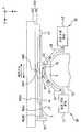
도 1 은 본 발명의 노광 장치의 일 실시형태를 나타내는 개략 구성도이다.
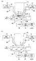
도 2 는 액체 공급 기구 및 액체 회수 기구를 나타내는 개략 구성도이다.
도 3 은 액체 공급 기구 및 액체 회수 기구를 나타내는 개략 평면도이다.
도 4 는 기판 스테이지의 평면도이다.
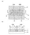
도 5(a) 및 5(b) 는 기준부재를 나타내는 도면이다.
도 6 은 본 발명의 노광 방법의 일 실시형태를 나타내는 플로우차트도이다.
도 7 은 본 발명에 관련된 기판 스테이지의 별도의 실시형태를 나타내는 모식도이다.
도 8 은 본 발명에 관련된 기판 스테이지의 별도의 실시형태를 나타내는 모식도이다.
도 9 는 더미 기판의 대기 장소를 구비한 노광 장치의 일 실시형태를 나타내는 평면도이다.
도 10(a) 및 10(b) 는 본 발명에 관련된 기판 스테이지의 별도의 실시형태를 나타내는 모식도이다.
도 11(a) 및 11(b) 는 본 발명에 관련된 기판 스테이지의 이동 궤적을 설명하기 위한 도면이다.
도 12 는 본 발명에 관련된 기판 스테이지의 이동 궤적을 설명하기 위한 도면이다.
도 13(a) 및 13(b) 는 본 발명에 관련된 액체 공급 기구의 동작을 설명하기 위한 도면이다.
도 14 는 반도체 디바이스의 제조공정의 일례를 나타내는 플로우차트도이다.1 is a schematic structural view showing an embodiment of an exposure apparatus of the present invention.
2 is a schematic configuration diagram showing a liquid supply mechanism and a liquid recovery mechanism.
3 is a schematic plan view showing a liquid supply mechanism and a liquid recovery mechanism.
4 is a plan view of the substrate stage.
5 (a) and 5 (b) are views showing the reference member.
6 is a flowchart showing one embodiment of the exposure method of the present invention.
7 is a schematic diagram showing a separate embodiment of the substrate stage according to the present invention.
8 is a schematic diagram showing another embodiment of the substrate stage related to the present invention.
Fig. 9 is a plan view showing an embodiment of an exposure apparatus having an atmospheric site on a dummy substrate. Fig.
10 (a) and 10 (b) are schematic diagrams showing another embodiment of the substrate stage according to the present invention.
Figs. 11 (a) and 11 (b) are diagrams for explaining movement trajectories of the substrate stage according to the present invention. Fig.
FIG. 12 is a view for explaining the movement locus of the substrate stage according to the present invention. FIG.
13 (a) and 13 (b) are diagrams for explaining the operation of the liquid supply mechanism according to the present invention.
14 is a flowchart showing an example of a manufacturing process of a semiconductor device.
이하, 본 발명의 노광 장치에 관해서 도면을 참조하면서 설명하지만, 본 발명은 이것에 한정되지 않는다.Hereinafter, the exposure apparatus of the present invention will be described with reference to the drawings, but the present invention is not limited thereto.
도 1 은 본 발명의 노광 장치의 일 실시형태를 나타내는 개략 구성도이다. 도 1 에 있어서, 노광 장치 (EX) 는, 마스크 (M) 를 지지하는 마스크 스테이지 (MST) 와, 기판 (P) 을 지지하는 기판 스테이지 (PST) 와, 마스크 스테이지 (MST) 에 지지되어 있는 마스크 (M) 를 노광광 (EL) 에 의해 조명하는 조명 광학계 (IL) 와, 노광광 (EL) 에 의해 조명된 마스크 (M) 의 패턴 이미지를 기판 스테이지 (PST) 에 지지되어 있는 기판 (P) 에 투영 노광하는 투영 광학계 (PL) 와, 노광 장치 (EX) 전체의 동작을 통괄 제어하는 제어 장치 (CONT) 를 구비하고 있다.1 is a schematic structural view showing an embodiment of an exposure apparatus of the present invention. 1, the exposure apparatus EX includes a mask stage MST for supporting a mask M, a substrate stage PST for supporting the substrate P, a mask (not shown) supported on the mask stage MST, An illumination optical system IL for illuminating the mask M with the exposure light EL and a pattern image of the mask M illuminated by the exposure light EL on the substrate P supported on the substrate stage PST, And a control device CONT for collectively controlling the operation of the entire exposure apparatus EX.
본 실시형태의 노광 장치 (EX) 는, 노광 파장을 실질적으로 짧게 하여 해상도를 향상시킴과 함께 초점 심도를 실질적으로 넓히기 위해 액침법을 적용한 액침 노광 장치로서, 기판 (P) 상에 액체 (LQ) 를 공급하는 액체 공급 기구 (10) 와, 기판 (P) 상의 액체 (LQ) 를 회수하는 액체 회수 기구 (20) 를 구비하고 있다. 본 실시형태에 있어서, 액체 (LQ) 에는 순수 (純水) 가 사용된다. 노광 장치 (EX) 는, 적어도 마스크 (M) 의 패턴 이미지를 기판 (P) 상에 전사하고 있는 동안, 액체 공급 기구 (10) 로부터 공급된 액체 (LQ) 에 의해 투영 광학계 (PL) 의 투영 영역 (AR1) 을 포함하는 기판 (P) 상의 일부에 (국소적으로) 액침 영역 (AR2) 을 형성한다. 구체적으로는, 노광 장치 (EX) 는, 투영 광학계 (PL) 의 선단부의 광학 소자 (2) 와 기판 (P) 표면과의 사이에 액체 (LQ) 를 채우고, 이 투영 광학계 (PL) 와 기판 (P) 사이의 액체 (LQ) 및 투영 광학계 (PL) 를 통해서 마스크 (M) 의 패턴 이미지를 기판 (P) 상에 투영함으로써, 기판 (P) 을 노광한다.The exposure apparatus EX of the present embodiment is a liquid immersion exposure apparatus in which a liquid immersion method is applied in order to substantially increase the resolution by increasing the exposure wavelength substantially to shorten the depth of focus, And a
여기서, 본 실시형태에서는, 노광 장치 (EX) 로서 마스크 (M) 와 기판 (P) 을 주사 방향 (소정 방향) 에서의 서로 다른 방향 (역방향) 으로 동기 이동하면서 마스크 (M) 에 형성된 패턴을 기판 (P) 에 노광하는 주사형 노광 장치 (이른바 스캐닝 스테퍼) 를 사용하는 경우를 예로 들어 설명한다. 이하의 설명에 있어서, 수평면 내에서 마스크 (M) 와 기판 (P) 의 동기 이동 방향 (주사 방향, 소정 방향) 을 X 축 방향, 수평면 내에서 X 축 방향과 직교하는 방향을 Y 축 방향 (비주사 방향), X 축 및 Y 축 방향에 수직이고 투영 광학계 (PL) 의 광축 (AX) 과 일치하는 방향을 Z 축 방향으로 한다. 또한, X 축, Y 축, 및 Z 축 둘레의 회전 (경사) 방향을 각각 θX, θY, 및 θZ 방향으로 한다. 또, 여기서 말하는 「기판」은 반도체 웨이퍼 상에 레지스트를 도포한 것을 포함하고, 「마스크」는 기판 상에 축소 투영되는 디바이스 패턴이 형성된 레티클을 포함한다.Here, in the present embodiment, as the exposure apparatus EX, a pattern formed on the mask M while moving the mask M and the substrate P synchronously in different directions (reverse direction) in the scanning direction (predetermined direction) (A so-called scanning stepper) for exposing the photoresist P to light is used as an example. In the following description, it is assumed that the synchronous movement direction (scanning direction, predetermined direction) of the mask M and the substrate P in the horizontal plane is the X-axis direction, the direction orthogonal to the X- Axis direction and the direction perpendicular to the X-axis and Y-axis directions and coinciding with the optical axis AX of the projection optical system PL is the Z-axis direction. The directions of rotation (inclination) about the X axis, the Y axis, and the Z axis are θX, θY, and θZ directions, respectively. Herein, the term " substrate " includes a resist coated on a semiconductor wafer, and the term " mask " includes a reticle on which a device pattern to be reduced projected is formed on a substrate.
조명 광학계 (IL) 는 마스크 스테이지 (MST) 에 지지되어 있는 마스크 (M) 를 노광광 (EL) 에 의해 조명하는 것으로, 노광용 광원, 노광용 광원으로부터 사출된 광속의 조도를 균일화하는 옵티컬 인터그레이터, 옵티컬 인터그레이터로부터의 노광광 (EL) 을 집광하는 콘덴서 렌즈, 릴레이 렌즈계, 노광광 (EL) 에 의한 마스크 (M) 상의 조명 영역을 슬릿 형상으로 설정하는 가변 시야 조리개 등을 갖고 있다. 마스크 (M) 상의 소정의 조명 영역은 조명 광학계 (IL) 에 의해 균일한 조도 분포의 노광광 (EL) 에 의해 조명된다. 조명 광학계 (IL) 로부터 사출되는 노광광 (EL) 으로는, 예를 들어 수은 램프로부터 사출되는 자외역의 휘선 (g 선, h 선, i 선) 및 KrF 엑시머 레이저광 (파장 248㎚) 등의 원자외광 (DUV 광) 이나, ArF 엑시머 레이저광 (파장 193㎚) 및 F2 레이저광 (파장 157㎚) 등의 진공 자외광 (VUV 광) 등이 사용된다. 본 실시형태에서는 ArF 엑시머 레이저광이 사용된다. 전술한 바와 같이, 본 실시형태에서의 액체 (LQ) 는 순수로서, 노광광 (EL) 이 ArF 엑시머 레이저광이어도 투과 가능하다. 또 순수는 자외역의 휘선 (g 선, h 선, i 선) 및 KrF 엑시머 레이저광 (파장 248㎚) 등의 원자외광 (DUV 광) 도 투과 가능하다.The illumination optical system IL illuminates the mask M supported on the mask stage MST by the exposure light EL and includes an exposure light source, an optical integrator for uniformizing the illuminance of the light beam irradiated from the exposure light source, A condenser lens for condensing the exposure light EL from the integrator, a relay lens system, and a variable viewing aperture for setting the illumination area on the mask M by the exposure light EL in a slit shape. The predetermined illumination region on the mask M is illuminated by the illumination optical system IL with the exposure light EL of uniform illumination distribution. Examples of the exposure light EL emitted from the illumination optical system IL include light lines (g line, h line, i line) in an ultraviolet region emitted from a mercury lamp and KrF excimer laser light (wavelength 248 nm) And vacuum ultraviolet light (VUV light) such as ArF excimer laser light (wavelength 193 nm) and F2 laser light (wavelength 157 nm) are used. In the present embodiment, ArF excimer laser light is used. As described above, in the present embodiment, the liquid LQ is pure water, and the exposure light EL is transmissive even if it is ArF excimer laser light. Further, pure water can also transmit external light (DUV light) such as a bright line (g line, h line, i line) in the ultraviolet region and KrF excimer laser light (wavelength 248 nm).
마스크 스테이지 (MST) 는 마스크 (M) 를 지지하여 이동가능하며, 투영 광학계 (PL) 의 광축 (AX) 에 수직인 평면 내, 즉 XY 평면 내에서 2차원 이동 가능 및 θZ 방향으로 미소 회전 가능하다. 마스크 스테이지 (MST) 는 리니어 모터 등의 마스크 스테이지 구동 장치 (MSTD) 에 의해 구동된다. 마스크 스테이지 구동 장치 (MSTD) 는 제어 장치 (CONT) 에 의해 제어된다. 마스크 스테이지 (MST) 상에는 마스크 스테이지 (MST) 와 함께 이동하는 이동경 (50) 이 설치되어 있다. 또한, 이동경 (50) 에 대향하는 위치에는 레이저 간섭계 (51) 가 설치되어 있다. 마스크 스테이지 (MST) 상의 마스크 (M) 의 2차원 방향의 위치, 및 회전각은 레이저 간섭계 (51) 에 의해 실시간으로 계측되고, 계측 결과는 제어 장치 (CONT) 에 출력된다. 제어 장치 (CONT) 는 레이저 간섭계 (51) 의 계측 결과에 기초하여 마스크 스테이지 구동 장치 (MSTD) 를 구동함으로써 마스크 스테이지 (MST) 에 지지되어 있는 마스크 (M) 의 위치를 결정한다.The mask stage MST is capable of supporting the mask M and is two-dimensionally movable in a plane perpendicular to the optical axis AX of the projection optical system PL, i.e., in the XY plane, and is slightly rotatable in the? Z direction . The mask stage MST is driven by a mask stage driving device MSTD such as a linear motor. The mask stage driving device MSTD is controlled by the control device CONT. On the mask stage MST, a
투영 광학계 (PL) 는 마스크 (M) 의 패턴을 소정의 투영 배율 (β) 로 기판 (P) 에 투영 노광하는 것으로서, 기판 (P) 측의 선단부에 설치된 광학 소자 (렌즈: 2) 를 포함하는 복수의 광학 소자로 구성되어 있고, 이들 광학 소자는 경통 (PK) 에 의해 지지되어 있다. 본 실시형태에 있어서, 투영 광학계 (PL) 는, 투영 배율 (β) 이 예를 들어 1/4 또는 1/5 의 축소계이다. 또, 투영 광학계 (PL) 는 등배계 및 확대계 중 어느 것도 상관없다. 또, 투영 광학계 (PL) 는 반사 소자와 굴절 소자를 포함하는 반사굴절형의 투영 광학계일 수도 있고, 반사 소자만을 포함하는 반사형의 투영 광학계일 수도 있다. 또, 본 실시형태의 투영 광학계 (PL) 의 선단부의 광학 소자 (2) 는 경통 (PK) 에 대하여 착탈 (교환) 이 가능하게 설치되어 있다. 또한, 선단부의 광학 소자 (2) 는 경통 (PK) 으로부터 노출되어 있어, 액침 영역 (AR2) 의 액체 (LQ) 는 광학 소자 (2) 에 접촉한다. 이것에 의해, 금속으로 이루어지는 경통 (PK) 의 부식 등이 방지되어 있다.The projection optical system PL is for projecting and exposing the pattern of the mask M onto the substrate P at a predetermined projection magnification beta and includes an optical element (lens 2) provided at the front end of the substrate P And is composed of a plurality of optical elements, and these optical elements are supported by the lens barrel PK. In the present embodiment, the projection optical system PL has a projection magnification? Of, for example, 1/4 or 1/5. The projection optical system PL may be any of an equi-magnification system and a magnification system. The projection optical system PL may be a reflection-type projection optical system including a reflection element and a refractive element, or may be a reflection-type projection optical system including only a reflection element. The
광학 소자 (2) 는 형석으로 형성되어 있다. 형석은 물과의 친화성이 높기 때문에, 광학 소자 (2) 의 액체 접촉면 (2a) 의 대략 전체면에 액체 (LQ) 를 밀착시킬 수 있다. 즉, 본 실시형태에 있어서는 광학 소자 (2) 의 액체 접촉면 (2a) 과의 친화성이 높은 액체 (LQ: 물) 를 공급하도록 하고 있기 때문에, 광학 소자 (2) 의 액체 접촉면 (2a) 과 액체 (LQ) 와의 밀착성이 높다. 광학 소자 (2) 는 물과의 친화성이 높은 석영이어도 된다. 또 광학 소자 (2) 의 액체 접촉면 (2a) 에 친수화 (친액화) 처리를 실시하여, 액체 (LQ) 와의 친화성을 보다 높여도 된다.The
또, 노광 장치 (EX) 는 포커스 검출계 (4) 를 갖고 있다. 포커스 검출계 (4) 는 발광부 (4a) 와 수광부 (4b) 를 가지고, 발광부 (4a) 로부터 액체 (LQ) 를 통해서 기판 (P) 표면 (노광면) 에 경사 방향에서 검출광을 투사하여, 그 반사광을 수광부 (4b) 에서 수광한다. 제어 장치 (CONT) 는, 포커스 검출계 (4) 의 동작을 제어하는 것과 함께, 수광부 (4b) 의 수광 결과에 기초하여 소정 기준면에 대한 기판 (P) 표면의 Z 축 방향에서의 위치 (포커스 위치) 를 검출한다. 또한, 기판 (P) 표면에서의 복수의 각 점에서의 각 포커스 위치를 구함으로써, 포커스 검출계 (4) 는 기판 (P) 의 경사 방향의 자세를 구할 수도 있다. 또, 포커스 검출계 (4) 의 구성으로는, 예를 들어 일본 공개특허공보 평8-37149호에 개시되어 있는 것을 사용할 수 있다. 또한, 포커스 검출계 (4) 는 액체를 통하지 않고서 기판 (P) 의 표면에 검출광을 투사하는 것이어도 된다.In addition, the exposure apparatus EX has a
기판 스테이지 (PST) 는 기판 (P) 을 유지하여 이동 가능하며, 기판 (P) 을 기판 홀더 (PSH) 를 개재하여 유지하는 Z 스테이지 (52) 와, Z 스테이지 (52) 를 지지하는 XY 스테이지 (53) 를 구비하고 있다. XY 스테이지 (53) 는 베이스 (54) 상에 지지되어 있다. 기판 스테이지 (PST) 는 리니어 모터 등의 기판 스테이지 구동 장치 (PSTD) 에 의해 구동된다. 기판 스테이지 구동 장치 (PSTD) 는 제어 장치 (CONT) 에 의해 제어된다. 또, Z 스테이지와 XY 스테이지를 일체적으로 형성해도 됨은 물론이다. 기판 스테이지 (PST) 의 XY 스테이지 (53) 를 구동함으로써, 기판 (P) 의 XY 방향에서의 위치 (투영 광학계 (PL) 의 이미지면과 실질적으로 평행한 방향의 위치) 가 제어된다.The substrate stage PST is movable with holding the substrate P and includes a
기판 스테이지 (PST) (Z 스테이지 (52)) 상에는, 기판 스테이지 (PST) 와 함께 투영 광학계 (PL) 에 대하여 이동하는 이동경 (55) 이 설치되어 있다. 또한, 이동경 (55) 에 대향하는 위치에는 레이저 간섭계 (56) 가 설치되어 있다. 기판 스테이지 (PST) 상의 기판 (P) 의 2차원 방향의 위치, 및 회전각은 레이저 간섭계 (56) 에 의해 실시간으로 계측되고, 계측 결과는 제어 장치 (CONT) 에 출력된다. 제어 장치 (CONT) 는 레이저 간섭계 (56) 의 계측 결과에 기초하여 레이저 간섭계 (56) 에 의해 규정되는 2차원 좌표계 내에서 기판 스테이지 구동 장치 (PSTD) 를 통해서 XY 스테이지 (53) 를 구동함으로써 기판 스테이지 (PST) 에 지지되어 있는 기판 (P) 의 X 축 방향 및 Y 축 방향에 있어서의 위치를 결정한다.On the substrate stage PST (Z stage 52), a
또한, 제어 장치 (CONT) 는 기판 스테이지 구동 장치 (PSTD) 를 통해서 기판 스테이지 (PST) 의 Z 스테이지 (52) 를 구동함으로써, Z 스테이지 (52) 에 유지되어 있는 기판 (P) 의 Z 축 방향에서의 위치 (포커스 위치), 및 θX, θY 방향에서의 위치를 제어한다. 즉, Z 스테이지 (52) 는, 포커스 검출계 (4) 의 검출 결과에 기초하는 제어 장치 (CONT) 로부터의 지령에 따라서 동작하고, 기판 (P) 의 포커스 위치 (Z 위치) 및 경사각을 제어하여 기판 (P) 의 표면 (노광면) 을 투영 광학계 (PL) 및 액체 (LQ) 를 통해서 형성되는 이미지면에 맞추어 넣는다.The control device CONT drives the
기판 스테이지 (PST) (Z 스테이지 (52)) 상에는, 기판 (P) 을 둘러싸도록 보조 플레이트 (57) 가 설치되어 있다. 보조 플레이트 (57) 는 기판 홀더 (PSH) 에 유지된 기판 (P) 의 표면과 대략 같은 높이의 평면을 갖고 있다. 여기서, 기판 (P) 의 에지와 보조 플레이트 (57) 사이에는 0.1∼2㎜ 정도의 간극이 있지만, 액체 (LQ) 의 표면장력에 의해 그 간극으로 액체 (LQ) 가 흘러 드는 일이 거의 없고, 기판 (P) 의 둘레가장자리 근방을 노광하는 경우에도 보조 플레이트 (57) 에 의해 투영 광학계 (PL) 아래에 액체 (LQ) 를 유지할 수 있다. 또, 기판 홀더 (PSH) 는 기판 스테이지 (PST) (Z 스테이지 (52)) 와 별도 부재여도 되고, 기판 스테이지 (PST) (Z 스테이지 (52)) 와 일체적으로 형성할 수도 있다.An
투영 광학계 (PL) 의 선단 근방에는, 기판 (P) 상의 얼라인먼트 마크 (1) 또는 Z 스테이지 (52) 상에 형성된 기준부재 (3) 상의 기판측 기준 마크 (PFM) 를 검출하는 기판 얼라인먼트계 (5) 가 형성되어 있다. 또한, 마스크 스테이지 (MST) 의 근방에는, 마스크 (M) 와 투영 광학계 (PL) 를 통해서 Z 스테이지 (52) 상에 형성된 기준부재 (3) 상의 마스크측 기준 마크 (MFM) 를 검출하는 마스크 얼라인먼트계 (6) 가 형성되어 있다. 또, 기판 얼라인먼트계 (5) 의 구성으로는, 예를 들어 일본 공개특허공보 평4-65603호에 개시되어 있는 것을 사용할 수 있다. 또한 기판 얼라인먼트계 (5) 종단의 광학 소자 (기판 (P), 기판 스테이지 (PST) 에 가장 가까운 광학 소자) 의 주위에는 액체의 부착을 방지하도록 발액성의 커버 (도시 생략) 가 설치되어 있다. 또한, 기판 얼라인먼트계 (5) 종단의 광학 소자의 표면은 발액성 재료로 피막되어 있어, 액체 (LQ) 의 부착이 방지되어 있을 뿐만 아니라, 종단의 광학 소자에 액체가 부착하더라도 오퍼레이터가 용이하게 닦아 낼 수 있게 되어 있다. 또한, 기판 얼라인먼트계 (5) 종단의 광학 소자와 그 광학 소자를 유지하는 금속물질과의 사이에 액체가 침입하는 것을 방지하기 위한 V 링 등의 시일부재가 배치되어 있다. 또한, 마스크 얼라인먼트계 (6) 의 구성으로는, 예를 들어 일본 공개특허공보 평7-176468호에 개시되어 있는 것이나, 일본 공개특허공보 소58-7823호에 개시되어 있는 것을 사용할 수 있다.A
액체 공급 기구 (10) 는, 액침 영역 (AR2) 을 형성하기 위해서 기판 (P) 상에 소정의 액체 (LQ) 를 공급하고, 액체 (LQ) 를 송출 가능한 액체 공급 장치 (11) 와, 액체 공급 장치 (11) 에 공급관 (12) 을 통해서 접속되고, 이 액체 공급 장치 (11) 로부터 송출된 액체 (LQ) 를 기판 (P) 상에 공급하는 공급구를 갖는 공급 노즐 (13) 을 구비하고 있다. 공급 노즐 (13) 은 기판 (P) 표면에 근접하여 배치되어 있다.The
액체 공급 장치 (11) 는, 액체 (LQ) 를 수용하는 탱크 및 가압 펌프 등을 구비하고 있고, 공급관 (12) 및 공급 노즐 (13) 을 통해서 기판 (P) 상에 액체 (LQ) 를 공급한다. 또한, 액체 공급 장치 (11) 의 액체 공급 동작은 제어 장치 (CONT) 에 의해 제어되고, 제어 장치 (CONT) 는 액체 공급 장치 (11) 에 의한, 기판 (P) 상으로의 단위 시간당 액체 공급량을 제어할 수 있다. 또한, 액체 공급 장치 (11) 는 액체 (LQ) 의 온도 조정 기구를 갖고 있고, 장치가 수용되는 챔버 내의 온도와 대략 동일한 온도 (예를 들어 23℃) 의 액체 (LQ) 를 기판 (P) 상에 공급하도록 되어 있다. 또, 액체 (LQ) 를 공급하기 위한 탱크나 가압 펌프를 반드시 노광 장치 (EX) 에서 구비하고 있을 필요는 없고, 노광 장치 (EX) 가 설치되어 있는 공장 등의 설비를 이용할 수도 있다.The
액체 회수 기구 (20) 는 기판 (P) 상의 액체 (LQ) 를 회수하고, 기판 (P) 의 표면에 근접하여 배치된 회수 노즐 (23) 과, 이 회수 노즐 (23) 에 회수관 (22) 을 통해서 접속된 액체 회수 장치 (21) 를 구비하고 있다. 액체 회수 장치 (21) 는 예를 들어 진공 펌프 등의 진공계 (흡인 장치) 및 회수한 액체 (LQ) 를 수용하는 탱크 등을 구비하고 있고, 기판 (P) 상의 액체 (LQ) 를 회수 노즐 (23) 및 회수관 (22) 을 통해서 회수한다. 액체 회수 장치 (21) 의 액체 회수 동작은 제어 장치 (CONT) 에 의해 제어되고, 제어 장치 (CONT) 는 액체 회수 장치 (21) 에 의한 단위 시간당 액체 회수량을 제어할 수 있다. 또, 액체 (LQ) 를 회수하기 위한 진공계나 탱크를 반드시 노광 장치 (EX) 에서 구비하고 있을 필요는 없고, 노광 장치 (EX) 가 설치되어 있는 공장 등의 설비를 이용할 수도 있다.The
도 2 는, 노광 장치 (EX) 의 투영 광학계 (PL) 의 선단부, 액체 공급 기구 (10), 및 액체 회수 기구 (20) 근방을 나타내는 정면도이다. 주사 노광시에는, 투영 광학계 (PL) 선단의 광학 소자 (2) 의 바로 아래 투영 영역 (AR1) 에 마스크 (M) 의 일부의 패턴 이미지가 투영되고, 투영 광학계 (PL) 에 대하여, 마스크 (M) 가 -X 방향 (또는 +X 방향) 으로 속도 (V) 로 이동하는 데 동기하여 XY 스테이지 (53) 를 개재하여 기판 (P) 이 +X 방향 (또는 -X 방향) 으로 속도 (βㆍV: β 는 투영 배율) 로 이동한다. 그리고, 하나의 쇼트 영역에 대한 노광 종료 후에, 기판 (P) 의 스테핑에 의해 다음 쇼트 영역이 주사 개시 위치로 이동하고, 이하, 스텝 앤드 스캔 방식에 의해 각 쇼트 영역에 대한 노광 처리가 순차적으로 실시된다. 본 실시형태에서는, 기판 (P) 의 이동 방향을 따라서 액체 (LQ) 를 흐르게 하도록 설정되어 있다.2 is a front view showing the vicinity of the distal end portion of the projection optical system PL of the exposure apparatus EX, the
도 3 은, 투영 광학계 (PL) 의 투영 영역 (AR1) 과, 액체 (LQ) 를 X 축 방향에 공급하는 공급 노즐 (13: 13A∼13C) 과, 액체 (LQ) 를 회수하는 회수 노즐 (23: 23A, 23B) 의 위치 관계를 나타내는 도면이다. 도 3 에 있어서, 투영 광학계 (PL) 의 투영 영역 (AR1) 의 형상은 Y 축 방향으로 가늘고 긴 직사각형상으로 되어 있고, 그 투영 영역 (AR1) 을 X 축 방향으로 사이에 끼우도록, +X 방향측으로 3개의 공급 노즐 (13A∼13C) 이 배치되고, -X 방향측으로 2개의 회수 노즐 (23A, 23B) 이 배치되어 있다. 그리고, 공급 노즐 (13A∼13C) 은 공급관 (12) 을 통해서 액체 공급 장치 (11) 에 접속되고, 회수 노즐 (23A, 23B) 은 회수관 (22) 을 통해서 액체 회수 장치 (21) 에 접속되어 있다. 또한, 공급 노즐 (13A∼13C) 과 회수 노즐 (23A, 23B) 을 거의 180°회전시킨 위치 관계로, 공급 노즐 (15A∼15C) 과 회수 노즐 (25A, 25B) 이 배치되어 있다. 공급 노즐 (13A∼13C) 과 회수 노즐 (25A, 25B) 은 Y 축 방향으로 교대로 배열되고, 공급 노즐 (15A∼15C) 과 회수 노즐 (23A, 23B) 은 Y 축 방향으로 교대로 배열되어, 공급 노즐 (15A∼15C) 은 공급관 (16) 을 통해서 액체 공급 장치 (11) 에 접속되고, 회수 노즐 (25A, 25B) 은 회수관 (26) 을 통해서 액체 회수 장치 (21) 에 접속되어 있다.3 is a schematic view showing a state in which the projection area AR1 of the projection optical system PL and the supply nozzles 13 (13A to 13C) for supplying the liquid LQ in the X axis direction and the recovery nozzles 23 : 23A, 23B). 3, the projection area AR1 of the projection optical system PL has a rectangular shape elongated in the Y-axis direction. The projection area AR1 is arranged in the + X direction so as to sandwich the projection area AR1 in the X-
그리고, 화살표 Xa 로 나타내는 주사 방향 (-X 방향) 으로 기판 (P) 을 이동시켜 주사 노광하는 경우에는, 공급관 (12), 공급 노즐 (13A∼13C), 회수관 (22), 및 회수 노즐 (23A, 23B) 을 사용하여, 액체 공급 장치 (11) 및 액체 회수 장치 (21) 에 의한 액체 (LQ) 의 공급 및 회수가 이루어진다. 즉, 기판 (P) 이 -X 방향으로 이동할 때에는, 공급관 (12) 및 공급 노즐 (13: 13A∼13C) 을 통해서 액체 공급 장치 (11) 로부터 액체 (LQ) 가 기판 (P) 상에 공급됨과 함께, 회수 노즐 (23: 23A, 23B) 및 회수관 (22) 을 통해서 액체 (LQ) 가 액체 회수 장치 (21) 에 회수되어, 투영 광학계 (PL) 와 기판 (P) 사이를 채우도록 -X 방향으로 액체 (LQ) 가 흐른다. 한편, 화살표 Xb 로 나타내는 주사 방향 (+X 방향) 으로 기판 (P) 을 이동시켜 주사 노광하는 경우에는, 공급관 (16), 공급 노즐 (15A∼15C), 회수관 (26), 및 회수 노즐 (25A, 25B) 를 사용하여, 액체 공급 장치 (11) 및 액체 회수 장치 (21) 에 의해 액체 (LQ) 의 공급 및 회수가 이루어진다. 즉, 기판 (P) 이 +X 방향으로 이동할 때에는, 공급관 (16) 및 공급 노즐 (15: 15A∼15C) 을 통해서 액체 공급 장치 (11) 로부터 액체 (LQ) 가 기판 (P) 상에 공급됨과 함께, 회수 노즐 (25: 25A, 25B) 및 회수관 (26) 을 통해서 액체 (LQ) 가 액체 회수 장치 (21) 에 회수되어, 투영 광학계 (PL) 와 기판 (P) 사이를 채우도록 +X 방향으로 액체 (LQ) 가 흐른다. 이와 같이, 제어 장치 (CONT) 는, 액체 공급 장치 (11) 및 액체 회수 장치 (21) 를 사용하여, 기판 (P) 의 이동 방향을 따라서 기판 (P) 의 이동 방향과 동일 방향으로 액체 (LQ) 를 흐르게 한다. 이 경우, 예를 들어 액체 공급 장치 (11) 로부터 공급 노즐 (13) 을 통해서 공급되는 액체 (LQ) 는 기판 (P) 의 -X 방향으로의 이동에 동반하여 투영 광학계 (PL) 와 기판 (P) 사이로 끌려 들어가듯이 하여 흐르기 때문에, 액체 공급 장치 (11) 의 공급 에너지가 작아도 액체 (LQ) 를 투영 광학계 (PL) 와 기판 (P) 사이에 용이하게 공급할 수 있다. 그리고, 주사 방향을 따라서 액체 (LQ) 를 흘리는 방향을 전환함으로써, +X 방향, 또는 -X 방향 중 어느 방향으로 기판 (P) 을 주사하는 경우에도 투영 광학계 (PL) 와 기판 (P) 사이를 액체 (LQ) 로 채울 수 있어, 높은 해상도 및 넓은 초점 심도를 얻을 수 있다.When the substrate P is moved in the scanning direction (-X direction) indicated by the arrow Xa to perform the scanning exposure, the
도 4 는, 기판 스테이지 (PST) 의 Z 스테이지 (52) 를 상방에서 본 개략 평면도이다. 직사각형상 Z 스테이지 (52) 의 서로 수직인 2개의 측면에는 이동경 (55) 이 배치되어 있고, Z 스테이지 (52) 의 대략 중앙에는 도시하지 않은 기판 홀더 (PSH) 를 통해서 기판 (P) 이 유지되어 있다. 기판 (P) 의 주위에는, 전술한 바와 같이, 기판 (P) 의 표면과 대략 같은 높이의 평면을 갖는 보조 플레이트 (57) 가 형성되고 있다. 그리고, 기판 (P) 상에는 노광 대상 영역인 복수의 쇼트 영역 (S1∼S20) 이 매트릭스형상으로 설정되어 있고, 각 쇼트 영역 (S1∼S20) 의 각각에 부수하여 얼라인먼트 마크 (1) 가 형성되어 있다. 또 도 4 에서는 각 쇼트 영역은 서로 인접하도록 도시되어 있지만 실제로는 서로 이간되어 있고, 얼라인먼트 마크 (1) 는 그 이간 영역인 스크라이브 라인 상에 형성되어 있다.4 is a schematic plan view of the
Z 스테이지 (52) 의 하나의 코너에는 기준부재 (3) 가 형성되어 있다. 기준부재 (3) 에는, 기판 얼라인먼트계 (5) 에 의해 검출되는 기준 마크 (PFM) 과, 마스크 얼라인먼트계 (6) 에 의해 검출되는 기준 마크 (MFM) 가 소정의 위치 관계로 떨어져서 배치되어 있다. 기준부재 (3) 의 기재에는 유리판부재 등의 광학부재가 사용되고 있고, 그 기재 상에 예를 들어 서로 다른 재료 (광반사율이 다른 재료) 로 패터닝함으로써 기준 마크 (PFM, MFM) 가 형성되어 있다. 그리고, 기준 마크 (PFM, MFM) 는 단차없이 형성되어 있고, 기준부재 (3) 의 표면은 거의 평탄하게 되어 있다. 따라서, 기준부재 (3) 의 표면은 포커스 검출계 (4) 의 기준면으로서의 역할도 할 수 있다.A
도 5 는 기준부재 (3) 를 나타내는 도면으로, 도 5(a) 는 평면도, 도 5(b) 는 도 5(a) 의 A-A 화살표 방향으로 본 단면도이다. 기준부재 (3) 는 유리판부재 등으로 이루어지는 기재 (33) 와, 그 기재 (33) 상에 패터닝된 서로 다른 광반사율을 갖는 제 1 재료 (31) 및 제 2 재료 (32) 를 갖고 있다. 본 실시형태에서는, 제 1 재료 (31) 는 광반사율이 낮은 산화크롬 (Cr2O3) 에 의해 구성되고, 제 2 재료 (32) 는 산화크롬보다 광반사율이 높은 크롬 (Cr) 에 의해 구성되어 있다. 그리고, 십자형상으로 형성된 기준 마크 (PFM, MFM) 는 산화크롬에 의해 형성되며, 그 주위를 크롬이 둘러싸도록 배치되고, 또 그 외측 영역에 산화크롬이 배치되어 있다. 또 사용하는 재료로는 상기 재료의 조합에 한정되지 않고, 예를 들어 제 1 재료를 알루미늄에 의해 구성하고, 제 2 재료를 크롬에 의해 구성해도 된다. 그리고, 기준 마크 (PFM, MFM) 의 상면은 단차를 가지지 않게 형성된 무단차 (無段差) 마크로 되어 있다.Fig. 5 is a plan view of the
이러한 무단차 마크를 형성하기 위해서는, 예를 들어 기재 (33) 상에 산화크롬막을 증착 등에 의해 형성한 후, 에칭 처리 등에 의해 산화크롬막의 소정 영역에 홈을 형성한다. 그리고, 상기 홈의 내부에 크롬을 형성한 후, 상면을 CMP 처리 (화학적 기계적 연마 처리) 등에 의해서 연마 처리함으로써, 산화크롬 및 크롬으로 이루어지는 무단차 마크를 형성할 수 있다. 또, 기재 (33) 에 홈을 형성하고, 그 홈에 크롬 또는 산화크롬을 매립한 후에 연마 처리하는 것에 의해서도 무단차 마크를 형성할 수 있다. 또는 기재 (33) 상에 광처리 (또는 열처리) 에 의해 변질되는 감광재 등의 재료를 도포하고, 형성하는 기준 마크에 따른 영역에 광 (또는 열) 을 쪼여 그 영역을 변질 (변색 등) 시키는 것에 의해서도 무단차 마크를 형성할 수 있다. 또는, 기재 (33) 에 크롬막을 증착하는 등에 의해 마크를 형성하고, 그 위를 석영 등의 광투과성 재료로 코팅함으로써, 기준부재 (3) 상면을 무단차화 (평탄화) 할 수도 있다.In order to form such an endless mark, for example, a chromium oxide film is formed on the
기준부재 (3) 의 상면 중, 기준 마크 (PFM, MFM) 를 포함하는 적어도 일부의 영역은 발액성 (발수성) 으로 되어 있다. 본 실시형태에서는, 기준부재 (3) 의 상면 전체영역이 발액성으로 되어 있다. 또한, 본 실시형태에서는, 기준부재 (3) 의 상면은, 발액성을 부여하는 발액화 처리를 실시함으로써 발액성으로 되어 있다. 발액화 처리로는, 예를 들어 발액성을 갖는 재료를 사용한 코팅 처리를 들 수 있다. 발액성을 갖는 재료로는, 예를 들어 불소계 화합물이나 규소 화합물, 또는 아크릴계 수지나 폴리에틸렌 등의 합성 수지를 들 수 있다. 또한, 표면 처리를 위한 박막은 단층막이어도 되고 복수의 층으로 이루어지는 막이어도 된다.At least a part of the upper surface of the
또, 기준 마크 (MFM, PFM) 를 형성하는 상기 제 1, 제 2 재료 (31, 32) 로서 발액성을 갖는 재료를 사용함으로써도, 기준부재 (3) 의 상면을 발액성으로 할 수 있다. 또한, 제 1 유리판부재 상에 크롬 등의 소정 재료에 의해 기준 마크를 형성하고, 그 위에 제 2 유리판부재를 포개어, 제 1, 제 2 유리판부재에 의해 상기 크롬 등으로 이루어지는 기준 마크를 사이에 끼우도록 하는 것에 의해서도, 평탄한 (무단차의) 상면을 갖는 기준부재를 형성할 수 있다. 이 경우, 발액화 처리는 제 2 유리판부재에 대하여 실시하면 되기 때문에, 발액화 처리를 원활하게 실시할 수 있다.The upper surface of the
또, 여기서는, 기준 마크 (PFM, MFM) 는 열십자형상으로 형성되어 있지만, 그 형상은 열십자형상에 한정되지 않고, 각 검출계에 최적인 마크형상을 사용 가능하다. 또한, 기준 마크 (PFM, MFM) 는 강조되어 도시되어 있지만, 실제로는 수 ㎛ 정도의 선폭을 갖는 것이다. 또한, 마스크 얼라인먼트계 (6) 로서, 일본 공개특허공보 소58-7823호에 개시되어 있는 것을 사용하는 경우에는, 기준부재 (3) 에는 기준 마크 (MFM) 로서 광투과부가 형성된다. 이 경우에도, 석영 등의 광투과성 재료를 기준부재 (3) 의 광투과부에 매립하거나, 광투과성 재료로 기준부재 (3) 의 상면을 코팅하거나 하여 기준부재 (3) 의 상면을 무단차화해 두는 것이 바람직하다. 또한, 전술한 바와 같이 기준부재 (3) 의 상면은 포커스 검출계 (4) 의 기준면으로서 사용되지만, 포커스 검출계 (4) 의 기준면을 기준부재 (3) 와는 별도로 Z 스테이지 (52) 상에 형성해도 된다. 또한, 기준부재 (3) 와 보조 플레이트 (57) 는 일체로 형성되어 있어도 된다.Although the reference marks PFM and MFM are formed in the shape of a cross, the shape of the reference marks PFM and MFM is not limited to the cross shape, and a mark shape optimal for each detection system can be used. In addition, although the reference marks PFM and MFM are shown emphatically, they actually have line widths of about several micrometers. When the
다음으로, 상기 서술한 노광 장치 (EX) 를 사용하여 마스크 (M) 의 패턴을 기판 (P) 에 노광하는 순서의 일례에 관해서 도 6 의 플로우차트도를 참조하면서 설명한다.Next, an example of the procedure of exposing the pattern of the mask M onto the substrate P using the above-described exposure apparatus EX will be described with reference to the flowchart of Fig.
Z 스테이지 (52) 의 기판 홀더 (PSH) 에 기판 (P) 이 로드되고, 그 기판 홀더 (PSH) 에 기판 (P) 을 유지시킨다 (도 1 참조). 그리고, 액체 공급 기구 (10) 에서 액체 (LQ) 를 공급하기 전에, 기판 (P) 상에 액체 (LQ) 가 없는 상태에서 먼저 계측 처리가 실시된다. 제어 장치 (CONT) 는, 투영 광학계 (PL) 의 광축 (AX) 이 도 4 의 파선 화살표 C 를 따라서 진행하도록 레이저 간섭계 (56) 의 출력을 모니터하면서 XY 스테이지 (53) 를 이동한다. 그 이동 도중에, 기판 얼라인먼트계 (5) 는, 쇼트 영역 (S1∼S20) 에 부수하여 기판 (P) 상에 형성되어 있는 복수의 얼라인먼트 마크 (1) 를 액체 (LQ) 를 통하지 않고서 순차적으로 검출한다 (단계 SA1).The substrate P is loaded on the substrate holder PSH of the
여기서, 기판 얼라인먼트계 (5) 가 얼라인먼트 마크의 검출을 실시할 때에는 XY 스테이지 (53) 는 정지되고, 기판 얼라인먼트계 (5) 가 얼라인먼트 마크 (1) 의 검출을 하고 있을 때의 기판 스테이지 (PST) 의 위치는 레이저 간섭계 (56) 에 의해 계측된다. 그 결과, 레이저 간섭계 (56) 에 의해서 규정되는 좌표계 내에서의 각 얼라인먼트 마크 (1) 의 위치 정보가 계측된다. 기판 얼라인먼트계 (5) 및 레이저 간섭계 (56) 를 사용하여 검출된 얼라인먼트 마크 (1) 의 위치 정보의 검출 결과는, 제어 장치 (CONT) 로 출력된다. 또 본 실시형태의 기판 얼라인먼트계 (5) 에서는, 기판 스테이지 (PST) 를 정지시켜서 마크 상에 할로겐 램프로부터의 백색광 등의 조명광을 조사하고, 얻어진 마크의 화상을 촬상 소자에 의해 소정의 촬상 시야 내에서 촬상하여, 화상 처리에 의해 마크의 위치를 계측하는 FIA (필드 이미지 얼라인먼트) 방식이 채용되어 있다.When the
또한, 기판 얼라인먼트계 (5) 는 레이저 간섭계 (56) 에 의해 규정되는 좌표계 내에 검출 기준 위치를 갖고 있어, 얼라인먼트 마크 (1) 의 위치 정보는 그 검출 기준 위치와의 편차로서 검출된다.The
여기서, 본 실시형태에서는, 예를 들어 일본 공개특허공보 소61-44429호에 개시되어 있는, 이른바 EGA (인핸스드 글로벌 얼라인먼트) 방식에 의해 쇼트 영역 (S1∼S20) 의 위치 정보가 구해진다. 그 때문에 제어 장치 (CONT) 는, 기판 (P) 상에 형성된 복수의 쇼트 영역 (S1∼S20) 중, 적어도 3개의 영역 (EGA 쇼트 영역) 을 지정하여, 각 쇼트 영역에 부수된 얼라인먼트 마크 (1) 를 기판 얼라인먼트계 (5) 를 사용하여 검출한다. 또, 기판 얼라인먼트계 (5) 는 기판 (P) 상의 모든 얼라인먼트 마크 (1) 를 검출해도 된다.Here, in the present embodiment, the position information of the shot areas S1 to S20 is obtained by the so-called EGA (Enhanced Global Alignment) method disclosed in, for example, Japanese Patent Application Laid-Open No. 61-44429. Therefore, the control device CONT designates at least three areas (EGA shot areas) out of the plurality of shot areas S1 to S20 formed on the substrate P, and the alignment marks 1 ) Is detected by using the substrate alignment system (5). Further, the
또한, 그 XY 스테이지 (53) 의 이동 중에, 포커스 검출계 (4) 에 의해 기판 (P) 의 표면 정보가 액체 (LQ) 를 통하지 않고서 검출된다. 포커스 검출계 (4) 는, 투영 광학계 (PL) 와 액체 (LQ) 를 통해서 형성되는 패턴 이미지의 결상면과 기판 (P) 표면과의 어긋남을 검출한다. 포커스 검출계 (4) 에 의한 표면 정보의 검출은 기판 (P) 상의 모든 쇼트 영역 (S1∼S20) 마다 실시되고, 검출 결과는 기판 (P) 의 주사 방향 (X 축 방향) 의 위치를 대응시켜서 제어 장치 (CONT) 에 기억된다. 또, 포커스 검출계 (4) 에 의한 표면 정보의 검출은, 일부 쇼트 영역에 대하여 실시하는 것만으로도 좋다.During the movement of the
다음으로, 제어 장치 (CONT) 는, 얼라인먼트 마크 (1) 의 위치 정보의 검출 결과에 기초하여, 기판 (P) 상의 복수의 쇼트 영역 (S1∼S20) 각각의 위치 정보를 연산 처리 (EGA 처리) 에 의해 구한다 (단계 SA2).Next, based on the detection result of the positional information of the
EGA 방식에서는, 단계 SA1 에 있어서 지정된 상기 EGA 쇼트 영역에 부수된 얼라인먼트 마크 (1) 의 위치 정보 (좌표 위치) 를 기판 얼라인먼트계 (5) 를 사용하여 검출한 후, 그 검출치와 설계치에 기초하여 기판 (P) 상의 쇼트 영역 (S1∼S20) 의 배열 특성 (위치 정보) 에 관한 오차 파라미터 (오프셋, 스케일, 회전, 직교도) 를 최소 제곱법 등에 의해 통계 연산하여 결정한다. 그리고, 이 결정된 파라미터의 값에 기초하여, 기판 (P) 상의 모든 쇼트 영역 (S1∼S20) 에 대해 그 설계 상의 좌표치를 보정한다. 이것에 의해, 기판 얼라인먼트계 (5) 의 검출 기준 위치와, 기판 스테이지 (PST) 에 탑재된 기판 (P) 상의 각 쇼트 영역과의 위치 관계가 결정된다. 즉, 제어 장치 (CONT) 는, 레이저 간섭계 (56) 의 출력으로부터 기판 얼라인먼트계 (5) 의 검출 기준 위치에 대하여 기판 (P) 상의 각 쇼트 영역이 어디에 위치하고 있는지를 알 수 있다.In the EGA method, the positional information (coordinate position) of the
기판 (P) 의 얼라인먼트 마크 (1) 의 검출 및 기판 (P) 의 표면 정보의 검출이 종료되면, 기판 얼라인먼트계 (5) 의 검출 영역이 기준부재 (3) 상에 위치 결정되도록, 제어 장치 (CONT) 는 XY 스테이지 (53) 를 이동시킨다. 기판 얼라인먼트계 (5) 는 기준부재 (3) 상의 기준 마크 (PFM) 를 액체없이 검출하고, 레이저 간섭계 (56) 에 의해 규정되는 좌표계 내에서의 기준 마크 (PFM) 의 위치 정보를 검출한다 (단계 SA3).When the detection of the
기준 마크 (PFM) 의 위치 정보를 기판 얼라인먼트계 (5) 를 사용하여 검출함으로써, 레이저 간섭계 (56) 에 의해서 규정되는 좌표계 내에서의 기판 얼라인먼트계 (5) 의 검출 기준 위치와 기준 마크 (PFM) 와의 위치 관계를 검출하게 된다.The detection reference position of the
기판 얼라인먼트계 (5) 를 사용한 얼라인먼트 마크 (1) 의 위치 정보의 검출과 Z 스테이지 (52) 상의 기준 마크 (PFM) 의 위치 정보의 검출 양쪽이 완료된 후에, 제어 장치 (CONT) 는, 마스크 얼라인먼트계 (6) 에 의해 기준부재 (3) 상의 기준 마크 (MFM) 를 검출할 수 있도록 XY 스테이지 (53) 를 이동시킨다. 마스크 얼라인먼트계 (6) 는 투영 광학계 (PL) 를 통해서 기준 마크 (MFM) 를 관찰하기 때문에, 투영 광학계 (PL) 의 선단부와 기준부재 (3) 는 대향하고 있다. 여기서, 제어 장치 (CONT) 는 액체 공급 기구 (10) 및 액체 회수 기구 (20) 에 의한 액체 (LQ) 의 공급 및 회수를 시작하여, 투영 광학계 (PL) 선단부의 광학 소자 (2) 의 선단면과 기준부재 (3) 의 상면 사이를 액체 (LQ) 로 채워서 액침 영역을 형성한다. 또, 액침 영역 (AR2) 은, 기준부재 (3) 상에만 형성되는 것이 바람직하지만, 기준부재 (3) 와 보조 플레이트 (57) 에 걸쳐 형성되어 있어도 되고, 기준부재 (3) 와 보조 플레이트 (57) 와 기판 (P) 에 걸쳐 형성되어 있어도 된다.After both the detection of the positional information of the
다음으로, 제어 장치 (CONT) 는, 마스크 얼라인먼트계 (6) 에 의해 마스크 (M), 투영 광학계 (PL), 및 액체 (LQ) 를 통해서 기준 마크 (MFM) 를 검출한다 (단계 SA4).Next, the control device CONT detects the reference mark MFM through the mask M, the projection optical system PL, and the liquid LQ by the mask alignment system 6 (step SA4).
이것에 의해 투영 광학계 (PL) 와 액체 (LQ) 를 통해서, XY 평면 내에 있어서의 마스크 (M) 의 패턴 이미지의 투영 위치 정보가 기준 마크 (MFM) 를 사용하여 검출되고, 레이저 간섭계 (56) 에 의해 규정되는 좌표계 내에서의 패턴 이미지의 투영 위치와 기준 마크 (MFM) 와의 위치 관계가 계측된다. 또 본 실시형태의 마스크 얼라인먼트계 (6) 에서는, 마크에 대하여 광을 조사하여, CCD 카메라 등으로 촬상한 마크의 화상 데이터를 화상 처리하여 마크 위치를 검출하는 VRA (비주얼 레티클 얼라인먼트) 방식이 채용되어 있다.The projection position information of the pattern image of the mask M in the XY plane is detected using the reference mark MFM through the projection optical system PL and the liquid LQ and is detected by the
제어 장치 (CONT) 는, 기판 얼라인먼트계 (5) 의 검출 기준 위치와 패턴 이미지의 투영 위치와의 간격 (위치 관계) 인 베이스라인량을 구한다 (단계 SA5).The control device CONT obtains a baseline amount which is an interval (positional relationship) between the detection reference position of the
구체적으로는, 단계 SA3 에서 구한 기판 얼라인먼트계 (5) 의 검출 기준 위치와 기준 마크 (PFM) 와의 위치 관계, 단계 SA4 에서 구한 패턴 이미지의 투영 위치와 기준 마크 (MFM) 와의 위치 관계, 및 미리 정해져 있는 기준 마크 (PFM) (기준부재 (3a)) 와 기준 마크 (MFM) (기준부재 (3b)) 와의 위치 관계로부터, 레이저 간섭계 (56) 에 의해 규정되는 좌표계 내에서의 패턴 이미지의 투영 위치와 기판 얼라인먼트계 (5) 의 검출 기준 위치와의 위치 관계 (베이스라인량) 가 결정된다.Specifically, the positional relationship between the detection reference position and the reference mark PFM of the
이상과 같은 계측 처리가 종료되면, 제어 장치 (CONT) 는, 액체 공급 기구 (10) 에 의한 기준부재 (3) 상으로의 액체 (LQ) 공급 동작을 정지한다. 한편, 제어 장치 (CONT) 는 액체 회수 기구 (20) 에 의한 기준부재 (3) 상의 액체 (LQ) 회수 동작을 소정 기간 계속한다. 그리고, 상기 소정 기간이 경과한 후, 제어 장치 (CONT) 는 액체 회수 기구 (20) 에 의한 회수 동작을 정지한다. 이렇게 함으로써, 기준부재 (3) 상의 액체 (LQ) 가 회수된다. 또, 기준부재 (3) 와 보조 플레이트 (57) 가 일체적으로 형성되고, 기준부재 (3b) 와 기판 (P) 이 보조 플레이트 (57) 를 통해서 대략 같은 높이로 연속하고 있는 구성이 바람직하고, 이 경우에는, 액체 공급 기구 (10) 의 액체 공급 동작을 정지하는 일없이, 투영 광학계 (PL) 의 이미지면측에 액체 (LQ) 를 유지한 상태에서 액체 (LQ) 의 액침 영역을 기준부재 (3) 상에서 기판 (P) 상으로 이동할 수 있다.When the measurement process is completed as described above, the control device CONT stops the operation of supplying the liquid LQ onto the
이어서, 제어 장치 (CONT) 는, 투영 광학계 (PL) 와 기판 (P) 을 대향시킨 상태에서, 제어 장치 (CONT) 가 액체 공급 기구 (10) 및 액체 회수 기구 (20) 를 구동하여, 기판 (P) 상에 대한 액체 공급 동작 및 기판 (P) 상의 액체 회수 동작을 시작한다. 이것에 의해, 투영 광학계 (PL) 와 기판 (P) 사이에 액침 영역 (AR2) 이 형성된다. 그리고, 기판 (P) 상에 액침 영역 (AR2) 을 형성한 후, 패턴 이미지가 투영되어 기판 (P) 의 복수의 쇼트 영역 각각이 순차적으로 액침 노광된다 (단계 SA6).Subsequently, the control device CONT drives the
보다 구체적으로는, 단계 SA2 에서 구한 기판 얼라인먼트계 (5) 의 검출 기준 위치에 대한 각 쇼트 영역의 위치 정보, 및 단계 SA5 에서 구한 기판 얼라인먼트계 (5) 의 검출 기준 위치와 패턴 이미지의 투영 위치와의 위치 관계 (베이스라인량) 에 기초하여 XY 스테이지 (53) 를 이동하여, 기판 (P) 상의 각 쇼트 영역 (S1∼S20) 과 패턴 이미지를 위치 맞춤하면서, 각 쇼트 영역의 액침 노광 처리를 실시한다.More specifically, the position information of each shot area with respect to the detection reference position of the
기판 (P) 상의 각 쇼트 영역 (S1∼S20) 를 주사 노광할 때에는, 전술한 계측 처리 중에 구한 각 정보를 사용하여 노광 처리가 실시된다. 즉, 단계 SA2 에서 구한 쇼트 영역의 배열 (위치 정보) 에 기초하여, 각 쇼트 영역이 패턴 이미지의 투영 위치에 위치 맞춤되어 순차적으로 노광된다. 또, 기판 (P) 상의 각 쇼트 영역 내의 얼라인먼트 마크 (1) 를 기판 얼라인먼트계 (5) 에 의해 축차 검출하고 그 쇼트 영역에 중첩 노광하는 이른바 다이 바이 다이 방식을 실시해도 되지만, 그 경우, 기판 (P) 의 쇼트 영역의 노광 중에는 기판 (P) 상에 액체 (LQ) 를 배치하고, 기판 얼라인먼트계 (5) 에 의한 얼라인먼트 마크 (1) 의 검출 중에는 기판 (P) 상에는 액체 (LQ) 를 배치하지 않는 동작을 되풀이하게 되기 때문에, 본 실시형태와 같이 쇼트 영역의 배열 (위치 정보) 을 미리 구하고, 그 구한 배열에 의해 기판 (P) 을 축차 이동하는 구성이 바람직하다.When the shot areas S1 to S20 on the substrate P are scanned and exposed, exposure processing is performed using each piece of information obtained during the above-described measurement processing. That is, on the basis of the arrangement (position information) of the shot areas obtained in step SA2, each shot area is aligned to the projection position of the pattern image and sequentially exposed. It is also possible to perform the so-called die by-die method in which the
또, 각 쇼트 영역 (S1∼S20) 에 대한 주사 노광 중에는, 액체 (LQ) 의 공급 전에 구한 기판 (P) 의 표면 정보에 기초하여 포커스 검출계 (4) 를 사용하지 않고 기판 (P) 표면과 액체 (LQ) 를 통해서 형성되는 이미지면과의 위치 관계가 조정된다. 또, 액체 (LQ) 의 공급 전에 기판 (P) 의 표면 정보를 구하지 않고서, 주사 노광 중에 액체 (LQ) 를 통해서 기판 (P) 표면과 이미지면의 위치 관계를 검출하여 조정하도록 실시해도 되고, 양쪽을 실시하도록 해도 된다.During the scan exposure for each of the shot areas S1 to S20, the surface of the substrate P is scanned without using the
기판 (P) 상의 각 쇼트 영역 (S1∼S20) 의 주사 노광이 종료되면, 제어 장치 (CONT) 는 액체 공급 기구 (10) 에 의한 액체 공급을 정지한다. 한편, 제어 장치 (CONT) 는, 액체 공급 기구 (10) 에 의한 액체 공급을 정지한 후, 액체 회수 기구 (20) 의 구동을 소정 시간 계속한다. 이것에 의해, 기판 (P) 상의 액체 (LQ) 가 회수된다. 또, 기판 (P) 상의 액체 (LQ) 를 회수할 때에는, 기판 스테이지 (PST) 를 구동하여, 기판 (P) 과 액체 회수 기구 (20) 의 회수 노즐 (23) 을 상대적으로 이동하면서 액체 (LQ) 를 회수하도록 해도 된다.When the scanning exposure of each of the shot areas S1 to S20 on the substrate P ends, the control unit CONT stops the liquid supply by the
기판 (P) 의 노광 완료 후에 별도의 기판 (P') 을 기판 스테이지 (PST) 상에 유지하여 노광할 때에는, 기판 스테이지 (PST) 상의 기준 마크 (PFM, MFM) 의 위치 정보를 검출하지 않고, 기판 (P') 의 쇼트 영역과 마스크의 패턴 이미지의 투영 위치를 위치 맞춤할 수 있다. 그 경우에는, 별도의 기판 (P') 을 Z 스테이지 (52) 상의 기판 홀더 (PSH) 에 유지시킨 후, 쇼트 영역에 부수하여 형성된 얼라인먼트 마크 (1) 의 위치 정보를 기판 얼라인먼트계 (5) 를 사용하여 검출한다. 이것에 의해, 먼저 노광된 기판 (P) 과 마찬가지로, EGA 처리를 사용하여 기판 얼라인먼트계 (5) 의 검출 기준 위치에 대한 각 쇼트 영역의 위치 정보가 구해진다. 이것에 의해, 투영 광학계 (PL) 와 기판 (P') 이 대향되고, 기판 (P') 상의 각 쇼트 영역과 패턴 이미지가 위치 맞춤되어, 패턴 이미지를 기판 (P') 의 각 쇼트 영역에 노광할 수 있다.The position information of the reference marks PFM and MFM on the substrate stage PST is not detected when the substrate P is held and exposed on the substrate stage PST after exposure of the substrate P is completed, The projection position of the pattern image of the mask and the shot area of the substrate P 'can be aligned. In this case, after the substrate P 'is held on the substrate holder PSH on the
이와 같이, 복수의 기판 (P (P')) 을 순차적으로 노광할 때, 베이스라인량을 구하기 위한 기준 마크 (PFM, MFM) 의 검출 동작은, Z 스테이지 (52) (기판 홀더 (PSH)) 에 별도의 기판 (P') 이 유지될 때마다 실시할 필요는 없고, Z 스테이지 (52) 에 유지된 (로드된) 기판 (P') 상의 얼라인먼트 마크 (1) 의 위치 정보를 검출하고, 앞서 구한 베이스라인량에 기초하여 기판 (P') 을 이동함으로써, 기판 (P') 과 패턴 이미지를 효율적으로 고정밀도로 위치 맞춤할 수 있다. 그리고, 베이스라인량을 구하기 위한 기준 마크 (PFM, MFM) 의 검출 동작은, 미리 설정된 기판 처리 매수마다 또는 마스크를 교환하였을 때마다 등, 소정 기간마다 실시하면 된다.The detection operation of the reference marks PFM and MFM for obtaining the amount of the base line when sequentially exposing the plurality of substrates P (P ') is performed by the Z stage 52 (substrate holder PSH) The position information of the
이상 설명한 바와 같이, Z 스테이지 (52) 상의 기준 마크 (PFM) 를 기판 얼라인먼트계 (5) 에 의해 검출할 때에는 액체 (LQ) 를 통하지 않고서 검출함으로써, 액체 (LQ) 의 온도 변화 등의 영향을 받지 않고 기준 마크 (PFM) 를 양호하게 검출할 수 있다. 또한, 기판 얼라인먼트계 (5) 를 액침 대응으로 구성할 필요없이 종래의 검출계를 그대로 이용할 수 있다. 그리고, 마스크 얼라인먼트계 (6) 를 사용하여 Z 스테이지 (52) 상의 기준 마크 (MFM) 를 검출할 때에는, 액침 노광시와 마찬가지로 투영 광학계 (PL) 의 이미지면측에 액체 (LQ) 를 채우고 투영 광학계 (PL) 와 액체 (LQ) 를 통해서 검출함으로써, 그 검출 결과에 기초하여 패턴 이미지의 투영 위치를 정확하게 검출할 수 있다. 그리고, 이들 기판 얼라인먼트계 (5) 및 마스크 얼라인먼트계 (6) 의 검출 동작 중에 있어서의 기판 스테이지 (PST) 의 각각의 위치 정보에 기초하여, 기판 얼라인먼트계 (5) 의 검출 기준 위치와 패턴 이미지의 투영 위치와의 위치 관계 (거리) 인 베이스라인량을 정확하게 구할 수 있고, 이 베이스라인량에 기초하여 기판 (P) 에 대한 중첩 노광할 때에도 기판 (P) (쇼트 영역 (S1∼S20)) 과 마스크 (M) 의 패턴 이미지를 정확하게 위치 맞춤할 수 있다.As described above, when the reference mark PFM on the
본 실시형태에서는, 기준 마크 (MFM) (기준부재 (3)) 상에 액체 (LQ) 를 배치한 상태에서 마스크 얼라인먼트계 (6) 에 의해 마크 검출이 이루어지지만, 그 검출 동작 중에 있어서는 Z 스테이지 (52) 의 기판 홀더 (PSH) 에 기판 (P) 이 배치되어 있다. 이것에 의해, 가령 기준부재 (3) 상에서 액체 (LQ) 가 유출되어도 기판 홀더 (PSH) 내부나 기판 스테이지 (PST) 내부에 액체 (LQ) 가 침입하는 것을 방지할 수 있다. 또한, 액침 영역 (AR2) 이 보조 플레이트 (57) 의 내측 에지로부터 빠져 나오는 경우에도, 기판 홀더 (PSH) 내부나 기판 스테이지 (PST) 내부로 액체 (LQ) 가 침입하는 것을 방지할 수 있다. 따라서, 침입한 액체 (LQ) 에 기인하는 기판 스테이지 (PST) 내부의 예를 들어 전기기기의 고장이나 누전, 또는 기판 스테이지 (PST) 내부의 각 부재에 녹이 발생하는 등의 문제가 일어나는 것을 방지할 수 있다.In the present embodiment, the mark alignment is performed by the
또한, 전술한 바와 같이, 본 실시형태에서는, 기준부재 (3) 상의 기준 마크 (PFM, MFM) 를 검출할 때에 기준부재 (3) 상에 액체 (LQ) 가 배치되는 웨트 상태와 배치되지 않는 드라이 상태가 전환되게 되지만, 도 5 를 참조하여 설명한 바와 같이, 기준부재 (3) 상에 형성되는 기준 마크 (PFM, MFM) 를 단차가 생기지 않게 하였기 때문에, 예를 들어 드라이 상태로부터 웨트 상태로 전환된 때에도, 기준부재 (3) 상의 액체 (LQ) 중의 마크부분에 기포가 생성되기 어려워진다. 또한, 웨트 상태로부터 드라이 상태로 전환하기 위해서 기준부재 (3) 상으로부터 액체 (LQ) 를 회수할 때에도, 액체 (LQ) 를 양호하게 회수할 수 있어 마크부분에 액체 (LQ) 를 잔류시키는 일이 없다. 특히 본 실시형태에서는, 기준부재 (3) 의 상면이 발액성으로 되어 있기 때문에, 액체 (LQ) 를 더욱 양호하게 회수할 수 있다. 따라서, 예를 들어 마스크 얼라인먼트계 (6) 는 기포 등의 영향을 받는 일 없이 기준 마크 (MFM) 를 정확하게 검출할 수 있다. 기판 얼라인먼트계 (5) 는 잔류하는 액체 (LQ) 의 영향을 받지 않고 기준 마크 (PFM) 를 정확하게 검출할 수 있다.As described above, in the present embodiment, when the reference marks PFM and MFM on the
그런데, 본 실시형태에서는, 기판 얼라인먼트계 (5) 에 의해 기준 마크 (PFM) 를 검출할 때에는 기준부재 (3) 상에 액체 (LQ) 는 배치되지 않고, 마스크 얼라인먼트계 (6) 에 의해 기준 마크 (MFM) 를 검출할 때에는 기준부재 (3) 상에 액체 (LQ) 가 배치된다. 그리고, 마스크측 기준 마크 (MFM) 와 기판측 기준 마크 (PFM) 를 따로 따로 (비동시적으로) 검출하는 구성인데, 기준부재 (3) 상에서 기준 마크 (PFM) 와 기준 마크 (MFM) 가 충분히 떨어져 있어 기준 마크 (PFM) 부분이 액체 (LQ) 에 노출되지 않는 경우에는, 기준 마크 (PFM) 를 무단차 마크로 하지 않아도 된다. 또한, 마스크측 기준 마크 (MFM) 와 기판측 기준 마크 (PFM) 를 별도의 기준부재에 형성해도 된다. 그 경우, 본 실시형태와 같이, 마스크측 기준 마크 (MFM) 와 기판측 기준 마크 (PFM) 를 비동시적으로 검출하도록 함으로써, 기준 마크 (PFM) 가 형성된 기준부재 상에는 액침 영역을 형성할 필요가 없어진다. 따라서, 기준 마크 (PFM) 의 무단차화 등의 액침 대응을 할 필요가 없을 뿐 아니라, 워터 마크 등의 발생도 방지할 수 있다.However, in the present embodiment, when the reference mark PFM is detected by the
본 실시형태에서는, 우선 액체 (LQ) 를 통하지 않고서 기판 (P) 상의 얼라인먼트 마크 (1) 를 기판 얼라인먼트계 (5) 에 의해 검출함으로써 기판 (P) 상의 복수의 쇼트 영역 (S1∼S20) 의 위치 정보를 구하고 (단계 SA1, SA2), 이어서 액체 (LQ) 를 통하지 않고서 기판 스테이지 (PST) 상의 기준 마크 (PFM) 를 검출하고 (단계 SA3), 이어서 투영 광학계 (PL) 의 이미지면측에 액체 (LQ) 를 채우고 투영 광학계 (PL) 와 액체 (LQ) 를 통해서 마스크 얼라인먼트계 (6) 에 의해 기준 마크 (MFM) 를 검출함으로써 패턴 이미지의 투영 위치를 구하여 (단계 SA4), 기판 얼라인먼트계 (5) 의 검출 기준 위치와 패턴 이미지의 투영 위치와의 위치 관계 (거리) 인 베이스라인량을 정확하게 구한 후 (단계 SA5), 기판 (P) 을 액침 노광하는 (단계 SA6) 구성이다. 즉, 상기 단계 SA1∼단계 SA3 에 있어서는 투영 광학계 (PL) 의 이미지면측에 액체 (LQ) 가 채워지지 않고, 단계 SA4∼단계 SA6 에 있어서 투영 광학계 (PL) 의 이미지면측에 액체 (LQ) 가 채워지는 구성이다. 이렇게 함으로써, 투영 광학계 (PL) 의 이미지면측에 액체 (LQ) 를 채우지 않은 드라이 상태와 투영 광학계 (PL) 의 이미지면측에 액체 (LQ) 를 채운 웨트 상태의 전환 횟수를 적게 할 수 있어, 스루풋을 향상시킬 수 있다. 예를 들어 웨트 상태로부터 드라이 상태로 전환된 경우, 전환 후에 있어서 예를 들어 기준부재 (3) 의 상면 등에 잔존하고 있는 액체 (LQ) 를 제거하는 작업이 필요해지지만, 전환 횟수가 늘어나면 그 액체 제거 작업의 횟수도 많아져 처리 효율을 저하시킨다. 그러나, 전환 횟수를 저감함으로써, 스루풋을 향상시킬 수 있다.The alignment marks 1 on the substrate P are detected by the
기판 얼라인먼트계 (5) 에 의해 기준 마크 (PFM) 를 검출한 후 (단계 SA3), 기판 (P) 상의 얼라인먼트 마크 (1) 를 검출하고 (단계 SA1, SA2), 이어서, 마스크 얼라인먼트계 (6) 에 의해 투영 광학계 (PL) 및 액체 (LQ) 를 통해서 기준 마크 (MFM) 의 검출을 한 후 (단계 SA4, SA5), 기판 (P) 을 액침 노광 처리하는 (단계 SA6) 것에 의해서도, 전술한 본 실시형태와 마찬가지로 드라이 상태와 웨트 상태의 전환 횟수를 적게 할 수 있다. 한편, 본 실시형태와 같이, 기판 얼라인먼트계 (5) 에 의한 기준 마크 (PFM) 의 검출 동작과, 마스크 얼라인먼트계 (6) 에 의한 투영 광학계 (PL) 및 액체 (LQ) 를 통한 기준 마크 (MFM) 의 검출 동작을 연속적으로 실시하도록 하였기 때문에, 기판 얼라인먼트계 (5) 에 의한 기준 마크 (PFM) 의 검출 동작시에 있어서의 검출상태에 대하여, 마스크 얼라인먼트계 (6) 에 의한 기준 마크 (MFM) 의 검출 동작시에 있어서의 검출상태가 크게 변동하여 기판 얼라인먼트계 (5) 의 검출 기준 위치와 패턴 이미지의 투영 위치와의 위치 관계인 베이스라인량을 정확하게 계측할 수 없다는 문제를 회피할 수 있다. 예를 들어, 스테이지 구동을 실시하는 리니어 모터의 정지시와 구동시의 발열량의 차이 등에 기인하는 노광 장치 환경의 열적 변동에 의해, 투영 광학계 (PL) 와 얼라인먼트계 (5) 의 위치 관계의 물리적인 변동, 얼라인먼트계 (5) 의 광학 특성의 변동, 및 기판 스테이지 (PST) 의 위치를 계측하는 레이저 간섭계 (56) 의 계측 광로 상의 환경 (온도) 변동 등이 생길 가능성이 있다. 그 경우, 기판 얼라인먼트계 (5) 에 의한 기준 마크 (PFM) 의 검출 동작시와, 마스크 얼라인먼트계 (6) 에 의한 기준 마크 (MFM) 의 검출 동작시와의 시간적 간격이 크면, 상기 열적 변동에 의해 베이스라인량을 정확하게 계측할 수 없는 문제가 생길 가능성이 있다. 그러나, 본 실시형태와 같이, 기판 얼라인먼트계 (5) 에 의한 기준 마크 (PFM) 의 검출 동작과, 마스크 얼라인먼트계 (6) 에 의한 기준 마크 (MFM) 의 검출 동작을 연속적으로 실시함으로써 상기 문제를 회피할 수 있다.After the reference mark PFM is detected by the substrate alignment system 5 (step SA3), the
또, 도 6 의 플로우차트로 나타낸 얼라인먼트 시퀀스에 있어서는, 기판 (P) 상의 얼라인먼트 마크 (1) 를 액체를 통하지 않고서 검출하고 (단계 SA1), EGA 처리한 (단계 SA2) 후에, 기준 마크 (PFM) 의 검출을 액체를 통하지 않고서 실시하고 (단계 SA3), 또 그 후에, 기준 마크 (MFM) 의 검출을 투영 광학계 (PL) 와 액체를 통해서 실행하고 있는데 (단계 SA4), 단계 SA2 와 단계 SA3 을 교체해도 된다. 이 경우, 기준 마크 (PFM) 와 기준 마크 (MFM) 의 검출 간격이 도 6 의 시퀀스보다 다소 길어지지만, 도 6 의 시퀀스와 마찬가지로 액체 공급 및 회수 동작을 적은 횟수로 할 수 있기 때문에, 스루풋 면에서 유리하다. 또한 상기 서술한 실시형태에 있어서는, 기준 마크 (PFM) 와 기준 마크 (MFM) 를 따로 따로 형성하고 있지만, 하나의 기준 마크를 기판 얼라인먼트계 (5) 와 마스크 얼라인먼트계 (6) 에서 검출하도록 해도 된다. 그리고, 기준 마크 (PFM) 를 액체없이 검출하는 것과 기준 마크 (MFM) 를 액체를 통해서 검출하는 것을 실행하여 베이스라인량을 구한 후에, 기판 (P) 상의 얼라인먼트 마크 (1) 를 검출하도록 해도 된다.6, the
도 7 및 8 은 본 발명의 별도 실시형태를 나타내는 모식도이다. 도 7 은 투영 광학계 (PL) 가 기판 (P) 상에 배치되어 있는 상태를, 도 8 은 투영 광학계 (PL) 가 기준부재 (3) 상에 배치되어 있는 상태를 각각 나타내고 있다. 도 7 및 8 에 있어서, Z 스테이지 (52) 상에는, 기판 홀더 (PSH) 상에 기판 (P) 을 배치하기 위한 오목부 (60) 가 형성되어 있음과 함께, 기준부재 (3) 를 배치하기 위한 오목부 (61) 가 형성되어 있다. 그리고, 오목부 (60) 에 배치된 기판 (P) 의 상면과, 오목부 (61) 에 배치된 기준부재 (3) 의 상면과, Z 스테이지 (52) 의 상면은 대략 면일하게 되도록 형성되어 있다. 이렇게 함으로써, 기준부재 (3) 상의 기준 마크 (MFM) 를 액체 (LQ) 를 통해서 검출하기 때문에, 도 7 에 나타내는 상태로부터 도 8 에 나타내는 상태로 하는 경우라도, 투영 광학계 (PL) 의 이미지면측에 액체 (LQ) 를 유지한 상태에서 기판 스테이지 (PST) 를 XY 방향으로 이동시킬 수 있다. 물론, 도 8 에 나타내는 상태로부터 도 7 에 나타내는 상태로 하는 경우라도, 투영 광학계 (PL) 의 이미지면측에 액체 (LQ) 를 유지한 상태에서 기판 스테이지 (PST) 를 XY 방향으로 이동시킬 수 있다. 또한, 기준부재 (3) 상의 기준 마크 (MFM) 를 액체 (LQ) 를 통해서 검출하고 있는 경우, 기준부재 (3) 상에 형성되는 액체 (LQ) 의 액침 영역의 크기에 따라서는, 기준 마크 (MFM) 의 검출 동작 중에 기준부재 (3) 상의 액침 영역의 일부 (단부) 가 기판 홀더 (PSH) 가 배치되어 있는 오목부 (60) 에 배치되는 상황이 발생하는 일이 있을 수 있지만, 오목부 (60) 의 기판 홀더 (PSH) 에 기판 (P) 을 배치해 둠으로써, 오목부 (60) 내부로의 액체 (LQ) 의 침입을 방지할 수 있다. 또한, 기판 (P) 을 배치함으로써 오목부 (60) 를 평탄하게 할 수 있어, 오목부 (단차부) 에 기인하는 액침 영역의 부조 (不調) 를 방지할 수 있다. 또, 기준 마크가 형성된 기준부재 (3) 를 Z 스테이지 (52) 의 오목부 (61) 에 매설하는 구성 외에, 오목부 (61) 를 형성하지 않고 Z 스테이지 (52) 의 상면에 직접 기준 마크를 형성하도록 해도 된다.7 and 8 are schematic diagrams showing another embodiment of the present invention. Fig. 7 shows a state in which the projection optical system PL is arranged on the substrate P, and Fig. 8 shows a state in which the projection optical system PL is arranged on the
또, 상기 실시형태에서는, 기판 (P) 상의 얼라인먼트 마크 (1) 를 검출한 후에 마스크 얼라인먼트계 (6) 에 의해 기준 마크 (MFM) 를 검출하는 시퀀스를 채용하고 있기 때문에, 마스크 얼라인먼트계 (6) 에 의한, 액체 (LQ) 를 통한 기준 마크 (MFM) 의 검출 동작 중에는 디바이스를 제조하기 위한 기판 (P) 이 기판 홀더 (PSH) 에 배치되어 있다. 그러나, 베이스라인량을 단독으로 계측하는 경우나, 베이스라인량의 계측 후에, 기판 (P) 을 기판 홀더 (PSH) 상에 로드하는 시퀀스 등이 채용될 가능성이 있다. 그 경우에는, 더미 기판 (DP) 을 기판 홀더 (PSH) 에 배치하는 것도 물론 가능하다. 여기서, 더미 기판 (DP) 은 디바이스 제조용의 기판 (P) 과 거의 동일한 형상 및 크기를 갖는다. 또한 더미 기판 (DP) 은 기판 (P) 과 동일한 재료, 예를 들어 규소로 형성한 것이어도 되지만, 액체 (LQ) 와의 접촉에 의한 오염물의 용출 등이 없는 것이면 각종 재료를 더미 기판 (DP) 에 사용할 수 있다. 그 경우, 기판 홀더 (PSH) 에 더미 기판 (DP) 을 배치한 상태에서, 마스크 얼라인먼트계 (6) 에 의해 투영 광학계 (PL) 및 액체 (LQ) 를 통한 기준 마크 (MFM) 의 검출이 실시된다. 이어서, 기판 얼라인먼트계 (5) 에 의해 액체 (LQ) 없이 기준 마크 (PFM) 의 검출이 실시되어, 베이스라인량이 계측된다. 그 기판 얼라인먼트계 (5) 의 검출 동작의 전 또는 후에, 더미 기판 (DP) 이 기판 홀더 (PSH) 에서 언로드됨과 함께, 디바이스 제조용 기판 (P) 이 기판 홀더 (PSH) 에 로드된다. 그리고, 기판 (P) 상의 얼라인먼트 마크 (1) 가 기판 얼라인먼트계 (5) 에 의해 검출된 후, 기판 (P) 상의 얼라인먼트 마크 (1) 의 위치 정보와 베이스라인량에 기초하여, 기판 (P) 상의 쇼트 영역과 패턴 이미지과의 위치 맞춤이 실시되고, 액침 노광이 실시된다.In the above embodiment, since the sequence for detecting the reference mark MFM is used by the
도 9 는, 상기 더미 기판 (DP) 을 보관하는 더미 기판용 라이브러리 (70A) 를 구비한 노광 장치 (EX) 의 일례를 모식적으로 나타낸 평면도이다. 도 9 에 있어서, 노광 장치 (EX) 는 챔버 장치 (CH) 의 내부에 설치되어 있다. 챔버 장치 (CH) 의 내부는 공조계 (空調系) 에 의해서 소정 환경 (온도, 습도) 으로 유지되어 있다. 기판 스테이지 (PST) 는, 챔버 장치 (CH) 의 내부에 있어서 소정의 가동 범위 (SR) 에서 이동 가능하게 배치되어 있다. 노광 장치 (EX) 에는, 기판 (P) 을 반송하는 반송 장치 (80) 가 접속되어 있다. 반송 장치 (80) 에는, 기판 (P) 에 감광재를 도포하는 기능과 노광 처리 완료된 기판 (P) 을 현상하는 기능을 갖는 코터ㆍ디벨로퍼 (C/D) 가 인터페이스부 (IF) 를 통해서 접속되어 있다. 반송 장치 (80) 는, 기판 (P) 을 유지하여 반송하는 제 1 아암부 (81) 및 제 2 아암부 (82) 를 구비하고 있다. 제 1, 제 2 아암부 (81, 82) 각각은 가이드부 (81A, 82A) 에 안내되면서 이동한다. 제 1, 제 2 아암부 (81, 82) 및 가이드부 (81A, 82A) 는 제 2 챔버 장치 (CH2) 의 내부에 형성되어 있다. 코터ㆍ디벨롭퍼 (C/D) 에 의해 감광재가 도포된 노광 처리 전의 기판 (P) 은, 제 1 아암부 (81) 및 제 2 아암부 (82) 에 의해서 노광 장치 (EX) 의 챔버 장치 (CH) 내부로 반송된다. 기판 스테이지 (PST) 는, 노광 처리 전의 기판 (P) 이 제 2 아암부 (82) 에 의해서 로드될 때, 기판 교환 위치 (RP) 로 이동된다. 기판 교환 위치 (RP) 에서 기판 (P) 이 로드된 기판 스테이지 (PST) 는, 투영 광학계 (PL) 의 아래인 노광 처리 위치 (EP) 로 이동한다. 또한, 노광 처리가 끝난 기판 (P) 을 유지한 기판 스테이지 (PST) 는, 기판 교환 위치 (RP) 로 이동한다. 노광 처리 완료된 기판 (P) 은 기판 교환 위치 (RP) 에서 제 2 아암부 (82) (또는 별도의 아암부) 에 의해서 언로드되고, 제 1 아암부 (81) (또는 별도의 아암부) 에 의해서 인터페이스부 (IF) 를 통해서 코터ㆍ디벨롭퍼 (C/D) 에 반송된다.9 is a plan view schematically showing an example of an exposure apparatus EX including a
그리고, 더미 기판 (DP) 을 기판 홀더 (PSH) 에 배치할 때에는, 제어 장치 (CONT) 는, 예를 들어 제 2 아암부 (82) 를 사용하여 챔버 장치 (CH) 의 내부에 설치되어 있는 더미 기판 (DP) 의 대기 장소인 더미 기판용 라이브러리 (70A) 로부터 더미 기판 (DP) 을 꺼내어, 기판 교환 위치 (RP) 에 있어서, 기판 스테이지 (PST) 의 기판 홀더 (PSH) 에 로드한다. 그리고, 기판 홀더 (PSH) 에 더미 기판 (DP) 을 유지한 상태에서, 제어 장치 (CONT) 는, 전술한 바와 같은 예를 들어 마스크 얼라인먼트계 (6) 에 의해 투영 광학계 (PL) 및 액체 (LQ) 를 통한 기준 마크 (MFM) 의 검출을 실시한다.When the dummy substrate DP is placed in the substrate holder PSH, the control device CONT controls the dummy substrate DP so that the dummy substrate DP is held in the dummy substrate PS by using, for example, the
또한, 상기 액체 (LQ) 를 통한 검출 처리가 종료한 후, 더미 기판 (DP) 을 기판 스테이지 (PST) 로부터 언로드할 때에는, 우선, 제어 장치 (CONT) 는 액체 회수 기구 (20) 등을 사용하여 더미 기판 (DP) 에 부착ㆍ잔류하고 있는 액체 (LQ) 의 제거 작업을 실시한다. 그리고, 제어 장치 (CONT) 는, 액체 제거 처리가 실시된 더미 기판 (DP) 을 유지하는 기판 스테이지 (PST) 를 기판 교환 위치 (RP) 로 이동시킨다. 그리고, 제어 장치 (CONT) 는, 제 2 아암부 (82) (또는 별도의 아암부) 를 사용하여 기판 스테이지 (PST) 로부터 더미 기판 (DP) 을 언로드하여, 더미 기판 (DP) 의 대기 장소인 더미 기판용 라이브러리 (70A) 에 수납한다.When the dummy substrate DP is unloaded from the substrate stage PST after the detection processing through the liquid LQ is finished, first, the control device CONT uses the
또, 본 실시형태에 있어서는, 더미 기판용 라이브러리 (70A) 는, 노광 장치 (EX) 를 수용하는 챔버 장치 (CH) 의 내부에 설치되어 있지만, 도 9 중, 부호 70B 로 나타내는 바와 같이, 더미 기판용 라이브러리를 예를 들어 반송 장치 (80) 를 수용하는 제 2 챔버 장치 (CH2) 의 내부에 설치해도 된다. 또는, 코터ㆍ디벨롭퍼 (C/D) 의 내부에 더미 기판용 라이브러리를 배치해도 된다.In the present embodiment, the
또, 더미 기판 (DP) 은 발액성을 갖고 있는 것이 바람직하다. 본 실시형태에 있어서는, 더미 기판 (DP) 은 발액화 처리되어 발액성을 갖고 있다. 발액화 처리로는, 예를 들어 발액성을 갖는 재료를 사용한 코팅 처리를 들 수 있다. 발액성을 갖는 재료로는, 예를 들어 불소계 화합물이나 규소 화합물, 또는 아크릴계 수지나 폴리에틸렌 등의 합성 수지를 들 수 있다. 또한, 표면 처리를 위한 박막은 단층막이어도 되고 복수의 층으로 이루어지는 막이어도 된다.It is preferable that the dummy substrate DP has lyophobicity. In the present embodiment, the dummy substrate DP is lyophobic and has lyophobicity. As the lyophobic treatment, for example, a coating treatment using a liquid-repellent material may be mentioned. Examples of the material having lyophobic property include fluorine-based compounds, silicon compounds, and synthetic resins such as acrylic resins and polyethylene. The thin film for the surface treatment may be a single layer film or a film composed of a plurality of layers.
또한, 더미 기판 (DP) 의 발액성은 시간이 경과됨에 따라서 열화된다. 그래서, 더미 기판 (DP) 을, 그 발액성의 열화에 따라서 교환하도록 해도 된다. 또, 더미 기판 (DP) 을 발액성 재료 (예를 들어, 불소계 재료나 아크릴) 로 형성해도 된다.Furthermore, the lyophobicity of the dummy substrate DP deteriorates with time. Therefore, the dummy substrate DP may be exchanged in accordance with deterioration of the lyophobicity. Further, the dummy substrate DP may be formed of a liquid-repellent material (for example, a fluorine-based material or acrylic).
도 10 은 별도의 실시형태를 나타내는 모식도이다. 도 10 에 나타내는 바와 같이, Z 스테이지 (52) (기판 스테이지 (PST)) 에 오목부 (60) 를 형성하고, 그 오목부 (60) 의 내부에 오목부 (60) 에 따른 형상을 갖는 기판 홀더 (PSH) 를 배치하는 것과 함께, Z 스테이지 (52) 내부에 기판 홀더 (PSH) 를 승강하는 승강 장치 (63) 를 설치하도록 해도 된다. 그리고, 마스크 얼라인먼트계 (6) 에 의해서 액체 (LQ) 를 통한 기준 마크 (MFM) 의 검출 동작을 실시할 때에는, 도 10(a) 에 나타내는 바와 같이, 승강 장치 (63) 는 기판 홀더 (PSH) 를 상승시켜서 Z 스테이지 (52) 의 상면과 기판 홀더 (PSH) 의 상면을 면일하게 맞춘다. 이렇게 함으로써도, 기준 마크 (MFM) 를 액체 (LQ) 를 통해서 계측하기 위해 기준부재 (3) 상에 형성된 액침 영역의 액체 (LQ) 가 Z 스테이지 (52) (기판 스테이지 (PST)) 내부로 침입하는 등의 문제가 일어나는 것을 방지할 수 있다. 그리고, 액침 노광하기 위해서 디바이스 제조용 기판 (P) 을 기판 홀더 (PSH) 에 유지시킬 때에는, 도 10(b) 에 나타내는 바와 같이, 승강 장치 (63) 가 기판 홀더 (PSH) 를 하강시킴으로써 기판 (P) 을 배치하기 위한 오목부 (60) 가 형성된다. 또, 기판 (P) 을 탑재할 때에 기판 홀더 (PSH) 상에 액체 (LQ) 가 부착되어 있는 경우에는, 부착된 액체 (LQ) 를 제거 또는 회수하고 나서 기판 (P) 에 탑재하면 된다.10 is a schematic diagram showing another embodiment. 10, a
또, 상기 서술한 실시형태에 있어서는, 기판 스테이지 (PST) 상의 기준 마크 (MFM) 를 투영 광학계 (PL) 와 액체 (LQ) 를 통해서 검출할 때에 기판 (P) 및 더미 기판 (DP) 을 기판 홀더 (PSH) 에 유지하여, Z 스테이지 (52) 내부로 액체 (LQ) 가 침입하는 것을 방지하고 있지만, 기준 마크 (MFM) 의 검출에 한정하지 않고, Z 스테이지 (52) (기판 스테이지 (PST)) 상의 각종 계측 센서의 사용시 등, Z 스테이지 (52) (기판 스테이지 (PST)) 상면의 주변부에 액침 영역 (AR2) 을 형성할 때에는, 기판 (P) 이나 더미 기판 (DP) 을 기판 홀더 (PSH) 에 유지하거나, 도 10 과 같은 구성을 사용하여 Z 스테이지 (52) (기판 스테이지 (PST)) 내부로의 액체 (LQ) 의 침입을 방지하는 것이 바람직하다.In the above-described embodiment, when the reference mark MFM on the substrate stage PST is detected through the projection optical system PL and the liquid LQ, the substrate P and the dummy substrate DP are fixed to the substrate holder (The substrate stage PST) and the liquid LQ is prevented from entering the
그런데, 전술한 바와 같이, 베이스라인량을 구하기 위한 기준 마크 (PFM, MFM) 의 검출 동작은, 미리 설정된 기판 처리 매수마다 또는 마스크 (M) 를 교환하였을 때마다 등 소정 기간마다 실시하면 된다. 그리고, 상기 서술한 실시형태에 있어서는, 기판 (P) 을 기판 홀더 (PSH) 상에 로드하기 전에 베이스라인량을 단독으로 계측할 때 등에, 기판 홀더 (PSH) 에 더미 기판 (DP) 을 유지해 둠으로써 기판 홀더 (PSH) 내부나 기판 스테이지 (PST) 내부로 액체 (LQ) 가 침입하는 것을 방지하고 있다. 한편, 베이스라인량을 계측할 때에는, 더미 기판 (DP) 을 기판 홀더 (PSH) 에 유지하는 대신에, 노광 처리 완료된 기판 (P) 을 기판 홀더 (PSH) 에 유지한 상태에서, 베이스라인량을 구하기 위한 기준 마크 (PFM, MFM) 의 검출 동작을 실시하는 것에 의해서도 기판 홀더 (PSH) 내부나 기판 스테이지 (PST) 내부로 액체 (LQ) 가 침입하는 것을 방지할 수 있다. 그리고, 베이스라인량의 계측이 종료된 후, 그 노광 처리 완료된 기판 (P) 을 언로드하면 된다. 즉, 기판 (P) 의 노광을 종료한 후, 그 노광 처리 완료된 기판 (P) 을 기판 스테이지 (PST) 에 유지한 상태에서, 기판 얼라인먼트계 (5) 에 의한 기판 스테이지 (PST) 상의 기준 마크 (PFM) 의 위치 정보의 검출과 마스크 얼라인먼트계 (6) 에 의한 기판 스테이지 (PST) 상의 기준 마크 (MFM) 의 위치 정보의 검출을 실시하고, 그 기준 마크 (PFM, MFM) 의 위치 정보의 검출 결과에 기초하여 베이스라인량을 구한 후, 그 노광 처리 완료된 기판 (P) 을 기판 스테이지 (PST) 로부터 반출함으로써, 기판 홀더 (PSH) 내부나 기판 스테이지 (PST) 내부로 액체 (LQ) 가 침입하는 것을 방지할 수 있다.Incidentally, as described above, the detection operation of the reference marks PFM and MFM for obtaining the amount of baseline may be performed every predetermined number of times, such as every predetermined number of processed substrates or each time the mask M is exchanged. In the embodiment described above, the dummy substrate DP is held on the substrate holder PSH when the base line amount is measured alone before the substrate P is loaded on the substrate holder PSH Thereby preventing the liquid LQ from intruding into the substrate holder PSH or the substrate stage PST. On the other hand, at the time of measuring the amount of baseline, the amount of base line is set at a value in a state in which the substrate P having been subjected to the exposure processing is held in the substrate holder PSH, instead of holding the dummy substrate DP in the substrate holder PSH It is possible to prevent the liquid LQ from intruding into the substrate holder PSH or the substrate stage PST by performing the detection operation of the reference marks PFM and MFM for obtaining the reference marks PFM and MFM. After the completion of the measurement of the amount of the base line, the substrate P subjected to the exposure processing can be unloaded. That is to say, after the exposure of the substrate P is completed, the substrate mark P on the substrate stage PST by the
또, 노광 처리 전의 기판 (P) 을 기판 홀더 (PSH) 에 유지한 상태에서, 베이스라인량을 구하기 위한 기준 마크 (PFM, MFM) 의 검출 동작을 실시하는 구성도 생각할 수 있다. 그러나, 액체 (LQ) 를 통해서 기준 마크 (MFM) 를 검출할 때 등에, 노광 처리 전의 기판 (P) 상의 얼라인먼트 마크 (1) 에 액체 (LQ) 가 부착될 가능성이 높아진다. 기판 (P) 상의 얼라인먼트 마크 (1) 를 검출하는 기판 얼라인먼트계 (5) 는, 액체 (LQ) 를 통하지 않고서 (드라이 상태에서) 검출하도록 구성되어 있기 때문에, 노광 처리 전의 기판 (P) 상의 얼라인먼트 마크 (1) 를 기판 얼라인먼트계 (5) 에 의해 검출할 때에 얼라인먼트 마크 (1) 상에 액체 (LQ) 가 부착되어 있으면, 검출 정밀도의 열화를 초래한다. 따라서, 베이스라인량을 구하기 위한 기준 마크 (PFM, MFM) 를 검출할 때에 기판 홀더 (PSH) 에 유지시켜 둔 기판 (P) 은, 노광 처리 후의 기판 (P) 인 것이 바람직하다.It is also conceivable to perform the detection operation of the reference marks PFM and MFM for obtaining the amount of baseline while holding the substrate P before the exposure process on the substrate holder PSH. However, when the reference mark MFM is detected through the liquid LQ, there is a high possibility that the liquid LQ adheres to the
또, Z 스테이지 (52) (기판 스테이지 (PST)) 상에 기준부재나 각종 계측 센서 등의 계측 부재가 배치되어 있지 않은 경우라도, Z 스테이지 (52) (기판 스테이지 (PST)) 상에 액침 영역 (AR2) 을 형성하는 경우에는, 기판 (P) 이나 더미 기판 (DP) 을 기판 홀더 (PSH) 에 유지하거나, 도 10 과 같은 기구를 사용하여 Z 스테이지 (52) (기판 스테이지 (PST)) 내부로의 액체 (LQ) 의 침입을 방지하는 것이 바람직하다.Even when the measurement member such as the reference member or various measurement sensors is not disposed on the Z stage 52 (substrate stage PST), the liquid-
부연하자면, Z 스테이지 (52) (기판 스테이지 (PST)) 상의 기준부재나 각종의 계측 센서 등의 계측부재의 유무에 상관없이, Z 스테이지 (52) (기판 스테이지 (PST)) 의 오목부 (60) 가 기판 (P) 이나 더미 기판 (DP) 등으로 커버되어 있지 않은 경우에, Z 스테이지 (52) (기판 스테이지 (PST)) 상에 액침 영역 (AR2) 을 형성하는 것을 금지하는 것이 바람직하다.The recesses 60 (substrate stage PST) of the Z stage 52 (substrate stage PST) are arranged in the Z stage 52 (substrate stage PST) regardless of whether there is a measuring member such as a reference member or various measuring sensors on the
예를 들어, Z 스테이지 (52) (기판 스테이지 (PST)) 의 오목부 (60) 가 기판 (P) 이나 더미 기판 (DP) 등에 의해 커버되어 있지 않은 경우에, 제어 장치 (CONT) 는, 액체 공급 기구 (10) 에 의한 액체 공급을 금지하거나, 투영 광학계 (PL) 의 광학 소자 (2) 와 Z 스테이지 (52) (기판 스테이지 (PST)) 가 대향하지 않도록 Z 스테이지 (52) (기판 스테이지 (PST)) 의 XY 평면 내에서의 이동 범위를 제한할 수 있다.For example, when the
또, 제어 장치 (CONT) 는 노광 장치 (EX) 전체의 동작을 통괄 제어하고 있기 때문에, Z 스테이지 (52) (기판 스테이지 (PST)) 의 오목부 (60) 가 기판 (P) 이나 더미 기판 (DP) 등으로 커버되어 있는지 여부를 판단할 수 있지만, 후술하는 바와 같이 기판 (P) 이나 더미 기판 (DP) 등으로 커버되어 있는지 여부를 검출하는 검출기를 사용하는 것도 가능하다.Since the control device CONT controls the overall operation of the exposure apparatus EX as a whole, the
또한, 기판 얼라인먼트계 (5) 에 의해 기판 (P) 상의 얼라인먼트 마크 (1) 를 검출할 때, 전술한 바와 같이, 기판 (P) 상의 얼라인먼트 마크 (1) 에 액체 (LQ) 가 배치되어 있지 않은 (부착되어 있지 않은) 상태로 하는 것이 바람직하다. 기판 스테이지 (PST) 에 로드된 노광 처리 전의 기판 (P) 이, 공급 노즐 (13) 의 아래나 회수 노즐 (23) 의 아래, 또는 투영 광학계 (PL) 의 광학 소자 (2) 의 아래를 통과할 때에, 공급 노즐 (13) 이나 회수 노즐 (23), 또는 광학 소자 (2) 에 잔류ㆍ부착되어 있는 액체 (LQ) 가 기판 (P) 상으로 적하 또는 비산될 우려가 있다. 그리고, 그 적하된 액체 (LQ) 가 기판 (P) 상의 얼라인먼트 마크 (1) 상에 배치되어 (부착되어) 버리면, 기판 얼라인먼트계 (5) 는 얼라인먼트 마크 (1) 의 계측을 실시할 수 없어 계측 에러를 발생하거나, 계측이 가능하다고 해도 얼라인먼트 마크 (1) 의 이미지나 파형 신호가 왜곡되어 오계측되어, 얼라인먼트계 측정 밀도가 열화되는 등의 문제가 생긴다.When the
또는, 기판 스테이지 (PST) 상에서, 그 기판 스테이지 (PST) 에 유지된 기판 (P) 과는 다른 위치 (예를 들어 보조 플레이트 (57) 상이나 Z 스테이지 (52) 의 상면 위) 에 액침 영역 (AR2) 을 형성하면서, 기판 얼라인먼트계 (5) 가 기판 (P) 상의 얼라인먼트 마크 (1) 를 액체 (LQ) 를 통하지 않고서 계측하는 구성도 있다. 또는, 기판 (P) 상의 일부에 (국소적으로) 액침 영역 (AR2) 을 형성하면서, 그 액침 영역 (AR2) 의 외측에서 얼라인먼트 마크 (1) 를 기판 얼라인먼트계 (5) 에 의해 액체 (LQ) 를 통하지 않고서 검출하는 구성도 있다. 이 경우에 있어서도, 액침 영역 (AR2) 으로부터 액체 (LQ) 가 비산되거나, 액체 (LQ) 의 회수가 충분히 이루어지지 않으면, 기판 (P) 상의 얼라인먼트 마크 (1) 상에 액체 (LQ) 가 배치된 상태에서 그 얼라인먼트 마크 (1) 가 기판 얼라인먼트계 (5) 에 계측되는 문제가 생긴다.(For example, on the upper surface of the
그래서, 제어 장치 (CONT) 는, 기판 얼라인먼트계 (5) 의 검출 영역에 배치되기 전의 기판 (P) 상의 얼라인먼트 마크 (1) 가, 공급 노즐 (13) 이나 회수 노즐 (23), 또는 투영 광학계 (PL) 의 광학 소자 (2) 아래를 통과하지 않도록 기판 스테이지 (PST) 의 이동 궤적을 결정한다. 그리고 제어 장치 (CONT) 는, 결정한 이동 궤적에 기초하여 기판 스테이지 (PST) 를 이동시키면서, 기판 얼라인먼트계 (5) 를 사용하여 기판 (P) 상의 복수의 얼라인먼트 마크 (1) 각각을 순차적으로 계측한다.The control device CONT therefore determines whether or not the
도 11 은, 기판 (P) 상의 복수의 얼라인먼트 마크 (1) 각각을 기판 얼라인먼트계 (5) 에 의해 순차적으로 계측할 때의 동작을 설명하기 위한 도면이다. 도 11 에 있어서, 투영 광학계 (PL) 의 광학 소자 (2) 근방에는 공급 노즐 (13) 및 회수 노즐 (23) 이 배치되어 있고, 이들 광학 소자 (2), 공급 노즐 (13), 및 회수 노즐 (23) 의 +X측에는 기판 얼라인먼트계 (5) 가 배치되어 있다. 이러한 위치 관계에 있어서, 기판 얼라인먼트계 (5) 를 사용하여 기판 (P) 상의 복수의 얼라인먼트 마크 (1) 각각을 순차적으로 계측할 때, 먼저 제어 장치 (CONT) 는, 도 11(a) 에 나타내는 바와 같이, 기판 (P) 상의 가장 -X측에 형성되어 있는 쇼트 영역에 부수된 얼라인먼트 마크 (1) 를 기판 얼라인먼트계 (5) 의 검출 영역에 배치하고, 그 얼라인먼트 마크 (1) 를 기판 얼라인먼트계 (5) 에 의해 계측한다. 예를 들어 제어 장치 (CONT) 는, 기판 (P) 상의 쇼트 영역 (S10) 이나 (S11) (도 4 참조) 등에 부수된 얼라인먼트 마크 (1) 를 기판 얼라인먼트계 (5) 의 검출 영역에 배치한다. 이하의 설명에서는, 최초에 계측되는 상기 얼라인먼트 마크 (1) 를 「제 1 얼라인먼트 마크」라고 한다.11 is a view for explaining the operation when the plurality of alignment marks 1 on the substrate P are successively measured by the
여기서, 제어 장치 (CONT) 는, 노광 처리 전의 기판 (P) 을 기판 교환 위치 (RP) (도 9 참조) 에 있어서 기판 스테이지 (PST) 상에 로드한 후, 기판 (P) 상의 제 1 얼라인먼트 마크 (1) 를 기판 얼라인먼트계 (5) 의 검출 영역에 배치할 때에, 기판 (P) 상의 복수의 얼라인먼트 마크 (1) 중, 적어도 기판 얼라인먼트계 (5) 의 계측 대상인 얼라인먼트 마크 (1) 가 공급 노즐 (13) 이나 회수 노즐 (23), 또는 광학 소자 (2) 의 아래를 통과하지 않도록 기판 스테이지 (PST) 를 이동시킨다. 이것에 의해, 제 1 얼라인먼트 마크 (1) 는, 공급 노즐 (13) 등의 아래를 통과하지 않고, 기판 얼라인먼트계 (5) 의 검출 영역에 배치된다. 따라서, 제 1 얼라인먼트 마크 (1) 상에 공급 노즐 (13) 등으로부터 적하된 액체 (LQ) 가 배치된 상태에서, 그 제 1 얼라인먼트 마크 (1) 가 기판 얼라인먼트계 (5) 에 계측되는 문제를 방지할 수 있다.Here, the control device CONT loads the substrate P before the exposure process onto the substrate stage PST at the substrate exchange position RP (see Fig. 9) The
제 1 얼라인먼트 마크 (1) 의 검출이 종료된 후, 제어 장치 (CONT) 는 기판 스테이지 (PST) 를 -X측으로 이동하여, 제 1 얼라인먼트 마크 (1) 보다 +X측에 형성된 제 2 얼라인먼트 마크 (1) (예를 들어 쇼트 영역 (S12) 나 (S9) 등에 부수된 얼라인먼트 마크 (1)) 를 기판 얼라인먼트계 (5) 의 검출 영역에 배치한다. 여기서, 제어 장치 (CONT) 는, 기판 얼라인먼트계 (5) 의 검출 영역에 계측 대상인 얼라인먼트 마크 (1) 가 공급 노즐 (13) 등의 아래를 통과하지 않도록 기판 스테이지 (PST) 의 이동 궤적을 결정하고 있기 때문에, 기판 (P) 이 기판 스테이지 (PST) 에 로드된 후, 그 기판 (P) 상의 제 2 얼라인먼트 마크 (1) 가 기판 얼라인먼트계 (5) 의 검출 영역에 배치되기까지의 동안에, 제 2 얼라인먼트 마크 (1) 는 공급 노즐 (13) 등의 아래를 통과하지 않는다. 따라서, 제 2 얼라인먼트 마크 (1) 상에 공급 노즐 (13) 등으로부터 적하된 액체 (LQ) 가 배치되는 문제가 방지되어 있다. 또, 이미 기판 얼라인먼트계 (5) 에 계측된 제 1 얼라인먼트 마크 (1) 는, 공급 노즐 (13) 등의 아래를 통과해도 된다.After the detection of the
이하 마찬가지로, 도 11(b) 에 나타내는 바와 같이, 제어 장치 (CONT) 는, 제 2 얼라인먼트 마크 (1) 보다 +X측에 형성된 제 3, 제 4 얼라인먼트 마크 (1) 를 기판 얼라인먼트계 (5) 의 검출 영역에 순차 배치하여 계측한다. 이상의 동작은, 제어 장치 (CONT) 가 기판 스테이지 (PST) 의 위치를 레이저 간섭계 (56) 에서 모니터하면서, 노광 레시피에 따라서 기판 스테이지 구동 장치 (PSTD) 를 제어함으로써 실시된다.11 (b), the control device CONT controls the third and fourth alignment marks 1 formed on the + X side of the
또 여기서는, 제어 장치 (CONT) 는 기판 스테이지 (PST) 를 -X측으로 이동시켜, 기판 얼라인먼트계 (5) 의 검출 영역에 기판 (P) 상의 -X측 얼라인먼트 마크 (1) 로부터 +X측 얼라인먼트 마크 (1) 를 순차 배치하고 있는데, 기판 얼라인먼트계 (5) 가 투영 광학계 (PL) 의 -X측에 형성되어 있는 경우에는 기판 스테이지 (PST) 는 +X측으로 이동된다. 또한, 얼라인먼트 마크 (1) 를 검출하는 순서도 X 축 방향에 따른 순서에 한정되지 않는다. 또한, 전술한 바와 같이, 기판 (P) 상에 형성된 복수의 얼라인먼트 마크 (1) 모두를 기판 얼라인먼트계 (5) 에 의해 검출할 필요는 없다. 따라서, 기판 얼라인먼트계 (5) 의 계측 대상이 아닌 얼라인먼트 마크 (1) 는, 공급 노즐 (13) 등의 아래를 통과해도 된다. 요컨대, 기판 얼라인먼트계 (5) 의 검출 영역에 배치되기 전의 계측 대상인 얼라인먼트 마크 (1) 가, 공급 노즐 (13) 등의 아래를 통과하지 않으면 된다.Here, the control device CONT moves the substrate stage PST to the -X side so that the + X side alignment marks 1 on the substrate P on the detection area of the
이상 설명한 바와 같이, 제어 장치 (CONT) 는, 기판 얼라인먼트계 (5) 의 검출 영역에 얼라인먼트 마크 (1) 를 배치하기 위한 기판 스테이지 (PST) 의 이동 궤적을, 기판 얼라인먼트계 (5) 와 공급 노즐 (13) (및 회수 노즐 (23), 광학 소자 (2)) 과의 위치 관계에 따라서 결정하고 있기 때문에, 기판 얼라인먼트계 (5) 에 의해 계측되는 얼라인먼트 마크 (1) 에, 공급 노즐 (13) 등의 아래를 통과한 것에 기인하여 액체 (LQ) 가 부착되는 문제를 방지할 수 있다. 따라서, 기판 얼라인먼트계 (5) 가 액체 (LQ) 가 부착된 상태인 얼라인먼트 마크 (1) 를 계측하는 문제가 방지되기 때문에, 계측 에러나 오계측을 방지할 수 있다. 따라서, 노광 장치 (EX) 의 가동률이 향상되어, 노광 정밀도를 고도로 유지할 수 있다.As described above, the control apparatus CONT controls the substrate trajectory of the substrate stage PST for positioning the
또, 도 11 을 참조하여 설명한 실시형태의 경우, 투영 광학계 (PL) 의 이미지면측에 액체 (LQ) 를 유지한 상태에서, 기판 얼라인먼트계 (5) 에 의한 얼라인먼트 마크 (1) 의 검출을 실시하도록 해도 된다. 이 경우, 기판 스테이지 (PST) (Z 스테이지 (52)) 상면, 또는 기판 스테이지 (PST) 상면과 기판 (P) 표면에 걸치도록, 또는 기판 (P) 표면에 액침 영역 (AR2) 이 형성되지만, 도 11 로부터도 알 수 있듯이, 제어 장치 (CONT) 는, 기판 (P) 의 얼라인먼트 마크 (1) 가 액침 영역 (AR2) 의 액체 (LQ) (도 1 참조) 와 접촉하기 전에 기판 얼라인먼트계 (5) 에 의해 검출되도록) 기판 스테이지 (PST) 의 이동 궤적을 결정하고 있기 때문에, 기판 얼라인먼트계 (5) 가 액체 (LQ) 가 부착된 상태의 얼라인먼트 마크 (1) 를 계측하는 문제를 방지할 수 있다.11, the
또, 여기서는, 기판 얼라인먼트계 (5) 의 검출 영역에 배치되기 전의 기판 (P) 상 얼라인먼트 마크 (1) 가 공급 노즐 (13) 등의 아래를 통과하지 않도록 하고 있지만, 기판 얼라인먼트계 (5) 의 검출 영역에 배치되기 전의 기준 마크 (PFM) 가 공급 노즐 (13) 등의 아래를 통과하지 않도록, 기판 스테이지 (PST) 의 이동 궤적이 결정되어도 된다. 이와 같이, 얼라인먼트 마크 (1) 나 기준 마크 (PFM) 에 한하지 않고, 드라이 상태에서 계측되는 기판 스테이지 (PST) 상의 마크 (계측 대상) 가 액체 (LQ) 를 적하시킬 가능성이 있는 부재의 아래를 통과하지 않도록 기판 스테이지 (PST) 의 이동 궤적을 결정하도록 함으로써, 액체 (LQ) 를 통하지 않은 마크 계측 정밀도를 향상시킬 수 있다.Here, although the
또 상기 서술한 실시형태에 있어서는, 기판 스테이지 (PST) 를 기판 교환 위치 (RP) 로부터 투영 광학계 (PL) 근방 (노광 처리 위치 (EP)) 까지 이동시킬 때나, 기판 (P) 상의 복수의 얼라인먼트 마크 (1) 를 계측할 때에 관련된 기판 스테이지 (PST) 의 이동 궤적에 대해 설명하였지만, 기준부재 (3) 상의 기준 마크 (PFM, MFM) 를 계측한 후, 기판 (P) 상의 얼라인먼트 마크 (1) 를 계측할 때 등에도, 기판 (P) 상의 얼라인먼트 마크 (1) 가 공급 노즐 (13) 등의 아래를 통과하지 않도록 기판 스테이지 (PST) 의 이동 궤적이 결정되는 것이 바람직하다. 예를 들어, 도 12 에 있어서, 기준부재 (3) 상의 기준 마크 (MFM) 를 마스크 얼라인먼트계 (6) 를 사용하여 액체 (LQ) 를 통해서 계측할 때에는, 제어 장치 (CONT) 는, 기준부재 (3) 상에 액침 영역 (AR2) 을 형성한 상태에서 기준 마크 (MFM) 를 계측한다. 그리고, 기준 마크 (MFM) 의 액체 (LQ) 를 통한 계측이 종료된 후, 제어 장치 (CONT) 는, 기준부재 (3) 상의 액체 (LQ) 를 액체 회수 기구 (20) 등을 사용하여 회수한다. 그 후, 제어 장치 (CONT) 는, 기판 얼라인먼트계 (5) 의 검출 영역에 기판 (P) 상의 얼라인먼트 마크 (1) 를 배치할 때에, 공급 노즐 (13) 등이 도 12 의 파선 화살표 K 를 따라서 진행하도록 레이저 간섭계 (56) 의 출력을 모니터하면서 XY 스테이지 (53) 를 이동시킨다. 그리고, 제어 장치 (CONT) 는, 기판 얼라인먼트계 (5) 의 검출 영역에 제 1 얼라인먼트 마크 (1) (예를 들어 쇼트 영역 (S10) 에 부수된 얼라인먼트 마크 (1)) 를 배치한다. 이 경우에 있어서도, 기판 얼라인먼트계 (5) 에 의해 계측되기 전의 얼라인먼트 마크 (1) 는 공급 노즐 (13) 등의 아래를 통과하지 않기 때문에, 공급 노즐 (13) 등으로부터 적하된 액체 (LQ) 가 부착되는 일이 없다.In the above-described embodiment, when the substrate stage PST is moved from the substrate exchange position RP to the vicinity of the projection optical system PL (exposure processing position EP) or when a plurality of alignment marks The reference marks PFM and MFM on the
또, 얼라인먼트 마크 (1) 에 액체가 부착되어 검출 에러가 난 경우에는, 얼라인먼트 마크 (1) 에 이물이 부착되어 검출 에러가 생긴 경우와 마찬가지로, 그 얼라인먼트 마크의 검출을 중지하고 그 근방의 얼라인먼트 마크를 대신 검출하도록 해도 되고, 그 기판 (P) 자체를 불량 기판으로서 취급하도록 해도 된다.
In the case where a detection error occurs due to the adhesion of the liquid to the
*또, 기판 얼라인먼트계 (5) 에 의해 기판 (P) 상의 얼라인먼트 마크를 드라이 상태에서 검출하였을 때에 얻어지는 마크 이미지나 신호 파형을 미리 기억해 놓고, 실제로 기판 얼라인먼트계 (5) 에 의해 얼라인먼트 마크 (1) 를 검출하였을 때에 얻어진 마크 이미지나 신호 파형이 기억되어 있는 것과 크게 다른 경우에는, 기판 얼라인먼트계 (5) 종단의 광학 소자와 얼라인먼트 마크 중 적어도 일방에 액체가 부착되어 있는 것으로 판단하고, 검출 에러를 출력하여, 오퍼레이터 등에게 부착된 액체의 닦아 내기 등을 재촉해도 된다.In addition, a mark image or a signal waveform obtained when the alignment mark on the substrate P is detected in the dry state by the
마찬가지로, 기판 얼라인먼트계 (5) 에 의해 기준 마크 (PFM) 를 드라이 상태에서 계측하였을 때에 얻어지는 마크 이미지나 신호 파형을 기억시켜 놓고, 베이스라인량의 계측 등과 같은 때에 실제로 기판 얼라인먼트계 (5) 에 의해 기준 마크 (PFM) 의 취득된 마크 이미지나 신호 파형이 기억되어 있는 것과 크게 다른 경우에는, 기판 얼라인먼트계 (5) 종단의 광학 소자와 기준 마크 (PFM) 중 적어도 일방에 액체가 부착되어 있는 것으로 판단하고, 검출 에러를 출력하여, 오퍼레이터 등에게 부착된 액체의 닦아 내기 등을 재촉해도 된다.Similarly, a mark image or a signal waveform obtained when the reference mark PFM is measured in the dry state by the
또, 기억되는 마크 이미지나 신호 파형은, 노광 장치 (EX) 내에서 기판 얼라인먼트계 (5) 를 사용하여 취득해도 되고, 노광 장치 (EX) 의 외부에서 취득하도록 해도 된다.The stored mark image or signal waveform may be acquired by using the
또한, 도 12 에 나타내는 기판 스테이지 (PST) 상에는, 예를 들어 일본 공개특허공보 소57-117238호에 개시되어 있는 조도 불균일 센서 (400) 나, 예를 들어 일본 공개특허공보 2002-14005호에 개시되어 있는 공간 이미지 계측 센서 (500) 가 설치되어 있다. 그리고, 이들 계측용 센서 (400, 500) 상에 액침 영역 (AR2) 을 형성한 상태에서, 액체 (LQ) 를 통해서 계측 처리를 실시하는 경우가 있다. 그 경우에 있어서도, 제어 장치 (CONT) 는, 센서 (400, 500) 에 의한 계측 처리를 종료한 후, 액체 회수 기구 (20) 등을 사용하여 액체를 회수한다. 그리고, 기판 (P) 상의 얼라인먼트 마크 (1) 를 기판 얼라인먼트계 (5) 의 검출 영역에 배치할 때에는, 제어 장치 (CONT) 는, 기판 얼라인먼트계 (5) 의 계측 대상인 기판 (P) 상의 얼라인먼트 마크 (1) 가 공급 노즐 (13) 등의 아래를 통과하지 않도록 기판 스테이지 (PST) 의 이동 궤적을 결정한다.On the substrate stage PST shown in Fig. 12, for example, an
도 13 은, 본 발명의 별도의 실시형태를 나타내는 모식도이다. 도 13(a) 에 있어서, 노광 장치 (EX) 는, 기판 홀더 (PSH) 에 기판 (P) 을 흡착 유지하기 위한 흡착 유지 기구 (90) 를 구비하고 있다. 흡착 유지 기구 (90) 는, 기판 홀더 (PSH) 의 상면의 복수의 위치 각각에 형성된 흡착구멍 (91) 과, 이들 복수의 흡착구멍 (91) 각각에 유로 (92) 를 통해서 접속된 진공계 (93) 를 구비하고 있다. 제어 장치 (CONT) 는 진공계 (93) 를 구동함으로써, 기판 홀더 (PSH) 의 상면에 탑재된 기판 (P) 의 이면을 흡착구멍 (91) 을 통해서 진공 흡착 유지한다.13 is a schematic diagram showing another embodiment of the present invention. 13 (a), the exposure apparatus EX includes a
흡착 유지 기구 (90) 의 유로 (92) 또는 진공계 (93) 의 압력에 관한 정보는, 압력 검출기 (94) 에 모니터되도록 되어 있다. 압력 검출기 (94) 는, 검출한 압력에 관한 정보에 기초하여 기판 홀더 (PSH) 상에 기판 (P) (또는 더미 기판 (DP)) 이 유지되어 있는지 여부를 검출할 수 있다. 즉, 압력 검출기 (94) 는, 흡착 유지 기구 (90) 에 의한 흡착 동작이 실행되고, 압력이 저하되지 않은 경우에는, 기판 홀더 (PSH) 상에 기판 (P) 이 유지되어 있지 않는 것으로 판단하고, 압력이 저하된 경우에는, 기판 홀더 (PSH) 상에 기판 (P) 이 유지되어 있는 것으로 판단한다. 또한, 압력 검출기 (94) 의 검출 결과 및 판단 결과는 제어 장치 (CONT) 에 출력된다.Information on the pressure in the
액체 공급 기구 (10) 의 공급관 (12) 의 도중에는, 공급관 (12) 의 유로를 개폐하는 밸브 (14) 가 설치되어 있다. 밸브 (14) 의 동작은 제어 장치 (CONT) 에서 제어된다.A
도 13(a) 에 나타내는 바와 같이, 기판 홀더 (PSH) 상에 기판 (P) 이 유지되어 있을 때, 전술한 바와 같이, 압력 검출기 (94) 는 압력에 관한 정보에 기초하여 기판 홀더 (PSH) 상에 기판 (P) 이 유지되어 있는 것을 검출할 수 있다. 그리고, 압력 검출기 (94) 가 기판 (P) 을 검출하였을 때, 제어 장치 (CONT) 는, 압력 검출기 (94) 의 검출 결과 (판단 결과) 에 기초하여 액체 공급 기구 (10) 에게 액체 공급이 가능하다는 지령을 내린다.13 (a), when the substrate P is held on the substrate holder PSH, as described above, the
한편, 도 13(b) 에 나타내는 바와 같이, 기판 홀더 (PSH) 상에 기판 (P) 이 유지되어 있을 때, 압력 검출기 (94) 는, 압력에 관한 정보에 기초하여 기판 홀더 (PSH) 상에 기판 (P) 이 유지되어 있지 않은 것을 검출할 수 있다. 그리고, 압력 검출기 (94) 가 기판 (P) 을 검출하지 않을 때에는, 제어 장치 (CONT) 는, 압력 검출기 (94) 의 검출 결과 (판단 결과) 에 기초하여 액체 공급 기구 (10) 에게 액체 공급 불가 지령을 내린다. 제어 장치 (CONT) 의 지령을 받은 액체 공급 기구 (10) 는, 예를 들어 밸브 (14) 에 의해서 공급관 (12) 의 유로를 닫는다. 이렇게 해서, 제어 장치 (CONT) 는 액체 공급 기구 (10) 에 의한 액체 공급을 정지한다.On the other hand, as shown in Fig. 13 (b), when the substrate P is held on the substrate holder PSH, the
전술한 바와 같이, 기판 홀더 (PSH) 에 기판 (P) 또는 더미 기판 (DP) 이 유지되어 있지 않은 상태에서 액침 영역 (AR2) 이 형성되거나 액체 공급 기구 (10) 에 의한 액체 공급이 실행되면, 기판 홀더 (PSH) 내부나 기판 스테이지 (PST) 내부로 액체 (LQ) 가 침입할 가능성이 있고, 예를 들어 액체 (LQ) 가 기판 스테이지 (PST) 내부로 침입하면, 녹을 발생시키거나, 내부에 배치되어 있는 전기기기나 슬라이딩부에 문제가 생겨, 수복에 많은 시간을 요하게 된다. 또는, 기판 홀더 (PSH) 의 유지면에 액체 (LQ) 가 가해지면, 흡착구멍 (91) 을 통해서 진공계 (93) 로 액체 (LQ) 가 유입되는 문제가 생긴다. 또한, 기판 홀더 (PSH) 의 유지면에 액체 (LQ) 가 부착되면, 기판 (P) 이 탑재되었을 때에 그 액체 (LQ) 가 윤활막으로서 기능하여, 기판 (P) 을 원하는 위치에 대하여 어긋난 상태로 유지하는 문제도 생긴다. 그래서, 본 실시형태와 같이, 기판 홀더 (PSH) 에 기판 (P) 또는 더미 기판 (DP) 이 유지되어 있는지 여부에 따라서 액체 공급 기구 (10) 의 동작을 제어함으로써, 기판 홀더 (PSH) 의 유지면에 액체 (LQ) 가 부착하거나, 기판 스테이지 (PST) 의 내부로 액체가 침입하는 것을 방지할 수 있다. 그리고, 기판 홀더 (PSH) 에 기판 (P) 또는 더미 기판 (DP) 이 유지되어 있지 않을 때에는 제어 장치 (CONT) 가 액체 공급 기구 (10) 에 의한 액체 공급을 정지함으로써, 기판 스테이지 (PST) 의 내부로의 액체의 침입 등을 방지할 수 있다.As described above, when the liquid immersion area AR2 is formed while the substrate P or the dummy substrate DP is not held in the substrate holder PSH, or when the liquid supply by the
또, 본 실시형태에 있어서는, 압력 검출기 (94) 의 검출 결과에 기초하여 기판 홀더 (PSH) 에 기판 (P) 또는 더미 기판 (DP) 이 유지되어 있는지 여부가 판단되고 있지만, 기판 스테이지 (PST) 나 기판 홀더 (PSH) 에 예를 들어 접촉식의 기판 유무 센서를 설치하고, 그 검출 결과에 기초하여 액체 공급 기구 (10) 의 동작을 제어하도록 해도 된다. 또는, 전술한 포커스 검출계 (4) 를 사용하여 기판 홀더 (PSH) 에 기판 (P) 또는 더미 기판 (DP) 이 유지되어 있는지 여부를 판단하고, 그 결과에 기초하여 액체 공급 기구 (10) 의 동작을 제어하도록 해도 된다. 또, 기판 홀더 (PSH) 에 기판 (P) (또는 더미 기판 (DP)) 이 유지되어 있을 때에, Z 스테이지 (52) (기판 스테이지 (PST)) 상에 액침 영역 (AR2) 이 형성되지 않도록, Z 스테이지 (52) (기판 스테이지 (PST)) 가 공급 노즐 (13) 이나 회수 노즐 (23), 또는 광학 소자 (2) 의 아래로 이동하는 것을 금지하도록 해도 된다.In the present embodiment, it is determined whether or not the substrate P or the dummy substrate DP is held by the substrate holder PSH based on the detection result of the
또한, 제어 장치 (CONT) 는, 압력 검출기 (94) 의 검출 결과에 따라서 기판 스테이지 (PST) 의 가동 영역을 변경하도록 해도 된다. 도 13 을 참조하여 설명한 실시형태와 같이, 기판 홀더 (PSH) 에 기판 (P) (또는 더미 기판 (DP)) 이 유지되어 있지 않을 때에, 액체 공급 기구 (10) 에 의한 액체 공급을 정지하였다고 해도, 공급 노즐 (13) 이나 회수 노즐 (23), 또는 투영 광학계 (PL) 의 광학 소자 (2) 에 잔류ㆍ부착되어 있는 액체 (LQ) 가 적하하여 기판 홀더 (PSH) 내부나 기판 스테이지 (PST) 내부로 침입할 가능성이 있다. 그 경우에 있어서도 기판 스테이지 (PST) 내부의 전기기기의 누전을 야기하거나, 녹이 발생되거나, 흡착구멍 (91) 을 통해서 액체 (LQ) 가 진공계 (93) 에 유입되거나, 또는 기판 홀더 (PSH) 의 유지면에 적하된 액체 (LQ) 가 윤활막으로서 기능하여 원하는 위치에 대하여 어긋난 상태에서 기판 (P) 을 유지하는 등의 문제가 생긴다. 그래서, 제어 장치 (CONT) 는, 기판 홀더 (PSH) 에 기판 (P) 이 유지되어 있는지 여부를 검출하는 검출기 (94) 의 검출 결과에 따라서, 기판 스테이지 (PST) 의 가동 영역을 변경한다.The control device CONT may change the movable region of the substrate stage PST in accordance with the detection result of the
구체적으로는, 기판 홀더 (PSH) 에 기판 (P) (또는 더미 기판 (DP)) 이 유지되어 있지 않을 때에는, 바꾸어 말하면 압력 검출기 (94) 가 기판 (P) 을 검출하지 않을 때에는, 제어 장치 (CONT) 는 기판 스테이지 (PST) 의 가동 영역을, 공급 노즐 (13) 이나 회수 노즐 (23), 또는 광학 소자 (2) 의 아래에 기판 홀더 (PSH) 가 위치하지 않는 영역으로 한다. 그리고, 제어 장치 (CONT) 는, 기판 홀더 (PSH) 에 기판 (P) 이 유지되어 있지 않은 경우, 레이저 간섭계 (56) 의 출력을 모니터하면서, 기판 홀더 (PSH) 가 공급 노즐 (13) 등의 아래를 통과하지 않도록 기판 스테이지 (PST) 를 이동한다. 이렇게 함으로써, 가령 공급 노즐 (13) 등으로부터 액체 (LQ) 가 적하되어도 기판 홀더 (PSH) 의 내부나 기판 스테이지 (PST) 의 내부로 액체 (LQ) 가 침입하는 것 등을 방지할 수 있다.Specifically, when the substrate P (or the dummy substrate DP) is not held on the substrate holder PSH, in other words, when the
또, 상기 서술한 실시형태에 있어서는, 기판 스테이지 (PST) 상에 액침 영역 (AR2) 을 형성할 때에 공급 노즐 (13) 로부터 액체 (LQ) 의 공급을 시작하도록 하고 있지만, 기판 스테이지 (PST) 와는 다른 소정의 물체와 투영 광학계 (PL) 사이에 유지된 액체를 회수하지 않고, 그 소정 물체 상에 형성되어 있는 액침 영역 (AR2) 을 기판 스테이지 (PST) 상으로 이동시킴으로써, 기판 스테이지 (PST) 상에 액침 영역 (AR2) 을 형성할 수도 있다.Although the supply of the liquid LQ from the
또, 상기 서술한 실시형태에 있어서는, 기판 (P) 상의 얼라인먼트 마크 (1) 및 기준 마크 (PFM) 를 액체를 통하지 않고서 검출하고, 기준 마크 (MFM) 의 검출은 액체를 통해서 실행하도록 되어 있지만, 기준부재 (3) 표면의 발액화, 기준부재 (3) 상면의 무단차화, 더미 기판 (DP) 의 사용 등에 관련된 발명은 기준 마크 (PFM) 와 기준 마크 (MFM) 를 동시에 검출할 수 있는 구성을 채용한 경우에도 적용 가능하며, 기판 (P) 상의 얼라인먼트 마크 (1) 및 기준 마크 (PFM) 를 액체를 통해서 검출하는 경우에도 적용 가능하다. 기준 마크 (PFM) 와 기준 마크 (MFM) 를 동시에 검출할 수 있는 구성의 노광 장치는, 예를 들어 일본 공개특허공보 평4-45512호 (대응 미국 특허 제5,138,176) 등에 개시되어 있고, 본 국제 출원에서 지정 또는 선택된 국가의 법령에서 허용하는 한도 내에서, 이들 개시를 원용하여 본문 기재의 일부로 한다.In the embodiment described above, the
또한, 기준부재 (3) 상에 액침 영역과 비액침 영역을 분리하여 형성할 수 있는 경우에는, 일본 공개특허공보 평4-45512호에 개시되어 있는 바와 같이 기준 마크 (PFM) 를 액체없이 검출하는 것과 기준 마크 (MFM) 를 액체를 통해 검출하는 것을 동시에 할 수 있는 구성을 채용해도 된다. 그 경우에는, 예를 들어 도 6 에 나타낸 얼라인먼트 시퀀스에 있어서, 단계 SA3 과 단계 SA4 를 동시에 실시할 수 있기 때문에 스루풋 면에서 유리하다. 그리고 또한, 기판 얼라인먼트계 (5) 가 기판 (P) 상의 얼라인먼트 마크 (1) 나 기준 마크 (PFM) 를 액체를 통해서 검출하는 구성인 경우에는, 일본 공개특허공보 평4-45512호에 개시되어 있는 것처럼 기준 마크 (PFM) 의 검출과 기준 마크 (MFM) 의 검출을 동시에 할 수 있는 구성을 채용해도 됨은 물론이다.In the case where the liquid immersion area and the non-liquid immersion area can be formed separately on the
또한, 상기 서술한 실시형태에 있어서는, 기준부재 상에 기준 마크 (PFM) 와 기준 마크 (MFM) 의 2가지 기준 마크를 형성했지만, 단일 기준 마크 (기준) 를 사용하여 단계 SA3 과 단계 SA4 를 실시하는 것도 가능하다.In the embodiment described above, two reference marks, the reference mark PFM and the reference mark MFM, are formed on the reference member. However, step SA3 and step SA4 are performed using a single reference mark (reference) It is also possible to do.
전술한 바와 같이, 본 실시형태에서의 액체 (LQ) 는 순수를 사용하였다. 순수는 반도체 제조 공장 등에서 용이하게 대량으로 입수할 수 있음과 함께, 기판 (P) 상의 포토레지스트나 광학 소자 (렌즈) 등에 대한 악영향이 없다는 이점이 있다. 또한, 순수는 환경에 대한 악영향이 없는 것과 함께 불순물의 함유량이 매우 낮기 때문에, 기판 (P) 의 표면 및 투영 광학계 (PL) 의 선단면에 설치된 광학 소자의 표면을 세정하는 작용도 기대할 수 있다. 또 공장 등으로부터 공급되는 순수의 순도가 낮은 경우에는, 노광 장치가 초순수 제조기를 갖도록 해도 된다.As described above, the liquid LQ in this embodiment uses pure water. Pure water can be easily obtained in large quantities in a semiconductor manufacturing factory or the like, and there is an advantage that there is no adverse effect on the photoresist and the optical element (lens) on the substrate P. Since the pure water has no adverse effect on the environment and has a very low content of impurities, it is also expected that the surface of the substrate P and the surface of the optical element provided on the front end face of the projection optical system PL are cleaned. When the purity of pure water supplied from a factory or the like is low, the exposure apparatus may have an ultrapure water producing machine.
그리고, 파장이 193㎚ 정도인 노광광 (EL) 에 대한 순수 (물) 의 굴절률 n 은 대략 1.44 인 것으로 알려져 있어, 노광광 (EL) 의 광원으로서 ArF 엑시머 레이저광 (파장 193㎚) 을 사용한 경우, 기판 (P) 상에서는 1/n, 즉 약 134㎚ 정도로 단파장화되어 높은 해상도가 얻어진다. 또, 초점 심도는 공기 중과 비교하여 약 n 배, 즉 약 1.44 배 정도로 확대되기 때문에, 공기 중에서 사용하는 경우와 동일한 정도의 초점 심도를 확보할 수 있으면 되는 경우에는 투영 광학계 (PL) 의 개구수를 보다 증가시킬 수 있어, 이 점에서도 해상도가 향상한다.It is known that the refractive index n of pure water (water) with respect to the exposure light EL having a wavelength of about 193 nm is approximately 1.44, and when ArF excimer laser light (wavelength 193 nm) is used as the light source of the exposure light EL , And on the substrate P, 1 / n, that is, about 134 nm, and a high resolution is obtained. Further, since the depth of focus is enlarged to about n times, that is, about 1.44 times as much as that in air, when the depth of focus can be secured to the same degree as in the case of using in air, the numerical aperture of the projection optical system PL The resolution can be improved even in this respect.
또, 상기 서술한 바와 같이 액침법을 사용한 경우에는, 투영 광학계의 개구수 (NA) 가 0.9∼1.3 이 되는 경우도 있다. 이와 같이 투영 광학계의 개구수 (NA) 가 커지는 경우에는, 종래부터 노광광으로서 사용되고 있는 랜덤 편광광에서는 편광 효과에 의해 결상 성능이 악화되는 경우도 있기 때문에 편광 조명을 사용하는 것이 바람직하다. 그 경우, 마스크 (레티클) 의 라인 앤드 스페이스 패턴의 라인 패턴의 긴 길이 방향에 맞춘 직선 편광 조명을 실시하고, 마스크 (레티클) 의 패턴으로부터의 S 편광 성분 (라인 패턴의 긴 길이 방향을 따른 편광 방향 성분) 의 회절광이 많이 사출되도록 하면 된다. 투영 광학계 (PL) 와 기판 (P) 표면에 도포된 레지스트 사이가 액체로 채워져 있는 경우, 투영 광학계 (PL) 와 기판 (P) 표면에 도포된 레지스트 사이가 공기 (기체) 로 채워져 있는 경우와 비교하여 콘트라스트의 향상에 기여하는 S 편광 성분의 회절광의 레지스트 표면에서의 투과율이 높아지기 때문에, 투영 광학계의 개구수 (NA) 가 1.0 을 초과하는 경우라도 높은 결상 성능을 얻을 수 있다. 또한, 위상 시프트 마스크나 일본 공개특허공보 평6-188169호에 개시되어 있는 라인 패턴의 긴 길이 방향에 맞춘 사입사 (斜入射) 조명법 (특히 다이볼 조명법) 등을 적절히 조합하면 더욱 효과적이다.When the liquid immersion method is used as described above, the numerical aperture (NA) of the projection optical system may be 0.9 to 1.3. When the numerical aperture (NA) of the projection optical system is increased as described above, it is preferable to use polarized illumination because the imaging performance deteriorates due to the polarization effect in the randomly polarized light conventionally used as the exposure light. In this case, the linearly polarized illumination corresponding to the longitudinal direction of the line pattern of the line and space pattern of the mask (reticle) is performed, and the S polarized light component (the polarization direction along the long longitudinal direction of the line pattern The diffracted light of the diffracted light component is emitted. Compared with the case where the space between the projection optical system PL and the resist applied to the surface of the substrate P is filled with air (gas) when the space between the projection optical system PL and the resist coated on the surface of the substrate P is filled with the liquid The transmittance of the diffracted light of the S-polarized light component contributing to the improvement of the contrast at the surface of the resist becomes high. Therefore, even when the numerical aperture NA of the projection optical system exceeds 1.0, high image forming performance can be obtained. It is also more effective to combine the phase shift mask and the oblique incidence illumination method (especially the die ball illumination method) in accordance with the longitudinal direction of the line pattern disclosed in Japanese Patent Application Laid-Open No. 6-188169.
또, 마스크 (레티클) 의 라인 패턴의 긴 길이 방향에 맞춘 직선 편광 조명 (S 편광 조명) 뿐만 아니라, 일본 공개특허공보 평6-53120호에 개시되어 있는 바와 같이, 광축을 중심으로 한 원의 접선 (둘레) 방향으로 직선 편광하는 편광 조명법과 사입사 조명법의 조합도 효과적이다. 특히, 마스크 (레티클) 의 패턴이 소정 일 방향으로 연장되는 라인 패턴뿐만 아니라, 복수의 다른 방향으로 연장되는 라인 패턴이 혼재하는 경우에는, 마찬가지로 일본 공개특허공보 평6-53120호에 개시되어 있는 바와 같이, 광축을 중심으로 한 원의 접선 방향으로 직선 편광하는 편광 조명법과 윤대 조명법을 병용함으로써, 투영 광학계의 개구수 (NA) 가 큰 경우라도 높은 결상 성능을 얻을 수 있다.Furthermore, as disclosed in Japanese Patent Laid-Open Publication No. 6-53120, not only a linearly polarized illumination (S polarized illumination) adapted to the longitudinal direction of the line pattern of the mask (reticle) A combination of a polarized illumination method and a quadrature illumination method in which linear polarization is performed in the (peripheral) direction is also effective. Particularly, when a pattern of a mask (reticle) extends not only in a line pattern extending in a predetermined direction but also in line patterns extending in a plurality of different directions, similarly, as disclosed in Japanese Laid-Open Patent Publication No. 6-53120 Similarly, by using the polarizing illumination method and the annular illumination method which are linearly polarized in the tangential direction of the circle around the optical axis, a high imaging performance can be obtained even when the numerical aperture (NA) of the projection optical system is large.
본 실시형태에서는, 투영 광학계 (PL) 의 선단에 광학 소자 (2) 가 장착되어 있고, 이 렌즈에 의해 투영 광학계 (PL) 의 광학 특성, 예를 들어 수차 (구면 수차, 코마 수차 등) 를 조정할 수 있다. 또, 투영 광학계 (PL) 의 선단에 장착되는 광학 소자 (2) 로는 투영 광학계 (PL) 의 광학 특성 조정에 사용되는 광학 플레이트여도 된다. 또는, 노광광 (EL) 을 투과 가능한 평행 평면판이어도 된다. 액체 (LQ) 와 접촉하는 광학 소자를, 렌즈보다 저렴한 평행 평면판으로 함으로써, 노광 장치 (EX) 의 운반, 조립, 조정시 등에 있어서 투영 광학계 (PL) 의 투과율, 기판 (P) 상에서의 노광광 (EL) 의 조도, 및 조도 분포의 균일성을 저하시키는 물질 (예를 들어 규소계 유기물 등) 이 그 평행 평면판에 부착되어도 액체 (LQ) 를 공급하기 직전에 그 평행 평면판을 교환하기만 하면 되어 액체 (LQ) 와 접촉하는 광학 소자를 렌즈로 하는 경우와 비교하여 그 교환 비용이 낮아지는 이점이 있다. 즉, 노광광 (EL) 의 조사에 의해 레지스트로부터 발생하는 비산 입자, 또는 액체 (LQ) 중의 불순물의 부착 등에 기인하여 액체 (LQ) 에 접촉하는 광학 소자의 표면이 더러워지기 때문에 그 광학 소자를 정기적으로 교환할 필요가 있지만, 이 광학 소자를 저렴한 평행 평면판으로 함으로써, 렌즈에 비하여 교환 부품의 비용이 낮고, 또 교환에 필요한 시간을 짧게 할 수 있어, 메인터넌스 비용 (러닝 코스트) 의 상승이나 스루풋의 저하를 억제할 수 있다.In this embodiment, the
또, 액체 (LQ) 의 흐름에 의해 생기는 투영 광학계 (PL) 선단의 광학 소자와 기판 (P) 사이의 압력이 큰 경우에는, 그 광학 소자를 교환 가능하게 하는 것이 아니라, 그 압력에 의해 광학 소자가 움직이지 않도록 견고하게 고정해도 된다.When the pressure between the optical element at the front end of the projection optical system PL caused by the flow of the liquid LQ and the substrate P is large, the optical element can not be replaced, It may be fixed firmly so as not to move.
또, 본 실시형태에서는 투영 광학계 (PL) 와 기판 (P) 표면과의 사이가 액체 (LQ) 로 채워져 있는 구성이지만, 예를 들어 기판 (P) 의 표면에 평행 평면판으로 이루어지는 커버 유리를 장착한 상태에서 액체 (LQ) 를 채우는 구성이어도 된다.In this embodiment, the liquid LQ is filled between the projection optical system PL and the surface of the substrate P. For example, a cover glass formed of a parallel flat plate is mounted on the surface of the substrate P The liquid LQ may be filled in one state.
또한, 상기 서술한 액침법을 적용한 노광 장치는, 투영 광학계 (PL) 의 종단광학 소자 (2) 의 사출측의 광로 공간을 액체 (순수) 로 채우고 웨이퍼 기판 (P) 을 노광하는 구성으로 되어 있지만, 국제 공개 제2004/019128호에 개시되어 있는 바와 같이, 투영 광학계 (PL) 의 종단 광학 소자 (2) 의 입사측의 광로 공간도 액체 (순수) 로 채우도록 해도 된다.
The exposure apparatus to which the liquid immersion method described above is applied is configured to fill the light path space on the irradiation side of the end
*또 본 실시형태의 액체 (LQ) 는 물이지만, 물 이외의 액체일 수도 있으며, 예를 들어 노광광 (EL) 의 광원이 F2 레이저인 경우, 이 F2 레이저광은 물을 투과하지 못하기 때문에, 액체 (LQ) 로는 F2 레이저광을 투과 가능한 예를 들어 과불화폴리에테르 (PFPE) 나 불소계 오일 등의 불소계 유체여도 된다. 이 경우, 액체 (LQ) 와 접촉하는 부분에는, 예를 들어 불소를 함유하는 극성이 작은 분자 구조의 물질로 박막을 형성함으로써 친액화 처리한다. 또한, 액체 (LQ) 로는, 그 밖에도 노광광 (EL) 에 대한 투과성이 있고 가능한 한 굴절률이 높으며, 투영 광학계 (PL) 나 기판 (P) 표면에 도포되어 있는 포토레지스트에 대하여 안정적인 것 (예를 들어 시더유 (cedar oil)) 을 사용할 수도 있다. 이 경우도 표면 처리는 사용하는 액체 (LQ) 의 극성에 따라서 실시된다.Further, the liquid LQ of the present embodiment is water but may be a liquid other than water. For example, when the light source of the exposure light EL is an F2 laser, the F2 laser light can not transmit water The liquid LQ may be a fluorine-based fluid such as a perfluoropolyether (PFPE) or a fluorine-based oil that can transmit F2 laser light. In this case, a lyophilic process is performed at a portion in contact with the liquid LQ, for example, by forming a thin film of a fluorine-containing material having a low polarity molecular structure. The liquid LQ may be any one that is transparent to the exposure light EL and has a refractive index as high as possible and stable to the photoresist applied to the surface of the projection optical system PL or the substrate P Cedar oil) may be used. In this case also, the surface treatment is carried out in accordance with the polarity of the liquid LQ to be used.
또, 상기 각 실시형태의 기판 (P) 으로는, 반도체 디바이스 제조용의 반도체 웨이퍼뿐만 아니라, 디스플레이 디바이스용의 유리 기판이나, 박막 자기 헤드용의 세라믹 웨이퍼, 또는 노광 장치에서 사용되는 마스크 또는 레티클의 원판 (합성 석영, 규소 웨이퍼) 등이 적용된다.As the substrate P in each of the above embodiments, not only a semiconductor wafer for semiconductor device fabrication but also a glass substrate for a display device, a ceramic wafer for a thin film magnetic head, or a mask or a reticle used in an exposure apparatus (Synthetic quartz, silicon wafer).
노광 장치 (EX) 로는, 마스크 (M) 와 기판 (P) 을 동기 이동하여 마스크 (M) 의 패턴을 주사 노광하는 스텝 앤드 스캔 방식의 주사형 노광 장치 (스캐닝 스테퍼) 외에, 마스크 (M) 와 기판 (P) 을 정지시킨 상태에서 마스크 (M) 의 패턴을 일괄 노광하고, 기판 (P) 을 순차적으로 스텝 이동시키는 스텝 앤드 리피트 방식의 투영 노광 장치 (스테퍼) 에도 적용할 수 있다. 또한, 본 발명은 기판 (P) 상에서 적어도 2개의 패턴을 부분적으로 겹쳐서 전사하는 스텝 앤드 스티치 방식의 노광 장치에도 적용할 수 있다.The exposure apparatus EX includes a masking type exposure apparatus (scanning stepper) in which a mask M and a substrate P are synchronously moved to scan-expose a pattern of the mask M, The present invention can also be applied to a step-and-repeat type projection exposure apparatus (stepper) in which the pattern of the mask M is exposed in a batch while the substrate P is stopped and the substrate P is sequentially moved stepwise. The present invention is also applicable to a step-and-stitch type exposure apparatus in which at least two patterns are partially overlapped and transferred on a substrate P.
또한, 본 발명은, 웨이퍼 등의 피처리 기판을 따로 따로 탑재하여 XY 방향으로 독립적으로 이동시킬 수 있는 2개의 스테이지를 구비한 트윈 스테이지형의 노광 장치에도 적용할 수 있다. 트윈 스테이지형의 노광 장치의 구조 및 노광 동작은, 예를 들어 일본 공개특허공보 평10-163099호 및 일본 공개특허공보 평10-214783호 (대응 미국 특허 6,341,007, 6,400,441, 6,549,269 및 6,590,634), 일본 특허공표공보 2000-505958호 (대응 미국 특허 5,969,441) 또는 미국 특허 6,208,407 에 개시되어 있고, 본 국제 출원에서 지정 또는 선택된 국가의 법령에서 허용하는 한도 내에서, 이들 개시를 원용하여 본문 기재의 일부로 한다.The present invention can also be applied to a twin-stage type exposure apparatus having two stages which can be independently moved in the X and Y directions by separately mounting a target substrate such as a wafer. The structure and exposure operation of the twin-stage type exposure apparatus are disclosed in, for example, Japanese Patent Application Laid-Open Nos. 10-163099 and 10-214783 (corresponding US patents 6,341,007, 6,400,441, 6,549,269 and 6,590,634) These disclosures are incorporated herein by reference in their entirety to the extent permitted by the laws of the country designated or elected in this international application, as published in the Public Publication No. 2000-505958 (corresponding US Patent 5,969,441) or US Patent 6,208,407.
2개의 스테이지를 구비한 트윈 스테이지형의 노광 장치로는, 기판의 노광이 실시되는 노광 스테이션과 기판 상의 쇼트 에어리어의 위치 맞춤이 실시되는 얼라인먼트 스테이션이 독립적으로 형성되어 있는 경우가 있다. 이 경우, 스루풋 향상을 위해, 제 1 스테이지 상의 기판이 노광 스테이션에서 노광되고 있을 때에, 제 2 스테이지 상의 기판이 얼라인먼트 스테이션에서 얼라인먼트된다. 그리고, 제 2 스테이지 상의 기판이 얼라인먼트된 후에 제 2 스테이지는 노광 스테이션으로 이동하여, 얼라인먼트 스테이션에서 위치 맞춤된 기판이 노광 스테이션에서 노광된다. 이 때, 제 2 스테이지 상의 기판은 얼라인먼트 스테이션에 있어서, 전술한 실시형태에서 설명한 기판 스테이지에 형성된 기준 마크에 대한 상대 위치가 구해지고, 그리고 노광 스테이션으로 제 2 스테이지가 이동되었을 때에, 노광 스테이션에서도 기준 마크를 기준으로 하여 결상 위치가 결정된다. 따라서, 전술한 실시형태에서 설명한 기준 마크는 트윈 스테이지형의 노광 장치에 있어서 노광 및 얼라인먼트 스테이션에서 유효하게 이용된다.In a twin-stage type exposure apparatus having two stages, there are cases where an exposure station where exposure of a substrate is performed and an alignment station where alignment of a shot area on the substrate is performed are independently formed. In this case, in order to improve the throughput, the substrate on the second stage is aligned in the alignment station when the substrate on the first stage is being exposed in the exposure station. Then, after the substrate on the second stage is aligned, the second stage moves to the exposure station, and the substrate aligned in the alignment station is exposed in the exposure station. At this time, the substrate on the second stage is moved in the aligning station to a position relative to the reference mark formed on the substrate stage described in the above-described embodiment, and when the second stage is moved to the exposure station, The image forming position is determined with reference to the mark. Therefore, the reference mark described in the above embodiment is effectively used in the exposure and alignment station in the twin-stage type exposure apparatus.
또, 상기 서술한 실시형태에 있어서는, 투영 광학계 (PL) 와 기판 (P) 사이를 국소적으로 액체로 채운 노광 장치를 채용하고 있지만, 노광 대상인 기판의 표면 전체가 액체로 덮이는 액침 노광 장치에도 본 발명을 적용할 수 있다. 노광 대상 기판의 표면 전체가 액체로 덮이는 액침 노광 장치의 구조 및 노광 동작은, 예를 들어 일본 공개특허공보 평6-124873호, 일본 공개특허공보 평10-303114호, 미국 특허 제5,825,043호 등에 상세하게 기재되어 있고, 본 국제 출원에서 지정 또는 선택된 국가의 법령에서 허용하는 한도 내에서, 이 문헌의 기재 내용을 원용하여 본문 기재의 일부로 한다.In the above-described embodiment, an exposure apparatus in which a space between the projection optical system PL and the substrate P is locally filled with liquid is employed. However, in the liquid immersion exposure apparatus in which the entire surface of the substrate, The present invention can be applied. The structure and exposure operation of the liquid immersion exposure apparatus in which the entire surface of the substrate to be exposed is covered with liquid are disclosed in, for example, Japanese Patent Laid-Open Nos. 6-124873, 10-303114, 5,825,043 And to the extent permitted by the laws of the country designated or selected in this international application, the contents of this document shall be used as part of the text.
또한, 본 발명은, 웨이퍼 등의 피처리 기판을 유지하여 이동 가능한 노광 스테이지와, 각종 기준부재나 계측 센서 등의 계측부재를 구비한 계측 스테이지를 구비한 노광 장치에도 적용할 수 있다. 이 경우, 상기 서술한 실시형태에 있어서 기판 스테이지 (PST) 에 배치되어 있는 기준부재나 각종 계측 센서의 적어도 일부를 계측 스테이지에 배치할 수 있다. 노광 스테이지와 계측 스테이지를 구비한 노광 장치는, 예를 들어 일본 공개특허공보 평11-135400호에 기재되어 있고, 본 국제 출원에서 지정 또는 선택된 국가의 법령에서 허용하는 한도 내에서, 이 문헌의 기재 내용을 원용하여 본문 기재의 일부로 한다.The present invention can also be applied to an exposure apparatus having an exposure stage capable of holding a substrate to be processed such as a wafer and a measurement stage having measurement members such as various reference members and measurement sensors. In this case, in the above-described embodiment, at least a part of the reference member and various measurement sensors arranged on the substrate stage PST can be arranged in the measurement stage. An exposure apparatus having an exposure stage and a measurement stage is disclosed in, for example, Japanese Patent Application Laid-Open No. 11-135400, and to the extent permitted by the laws and regulations of the country designated or selected in this international application, Shall be made as part of the text.
노광 장치 (EX) 의 종류로는, 기판 (P) 에 반도체 소자 패턴을 노광하는 반도체 소자 제조용의 노광 장치에 한정되지 않고, 액정 표시 소자 제조용 또는 디스플레이 제조용의 노광 장치나, 박막 자기 헤드, 촬상 소자 (CCD) 또는 레티클 또는 마스크 등을 제조하기 위한 노광 장치 등에도 널리 적용할 수 있다.The exposure apparatus EX is not limited to an exposure apparatus for manufacturing a semiconductor element that exposes a semiconductor element pattern on a substrate P but may be an exposure apparatus for manufacturing a liquid crystal display element or a display or a thin film magnetic head, (CCD), an exposure apparatus for manufacturing a reticle or a mask, and the like.
기판 스테이지 (PST) 나 마스크 스테이지 (MST) 에 리니어 모터를 사용하는 경우에는, 에어 베어링을 사용한 에어 부상형 및 로렌츠력 또는 리액턴스력을 사용한 자기 부상형 중 어느 것을 사용해도 상관없다. 또, 각 스테이지 (PST, MST) 는, 가이드를 따라서 이동하는 타입일 수도 있고, 가이드를 설치하지 않은 가이드리스 타입일 수도 있다. 스테이지에 리니어모터를 사용한 예는, 미국 특허 5,623,853 및 5,528,118 에 개시되어 있고, 각각 본 국제 출원에서 지정 또는 선택된 국가의 법령에서 허용하는 한도 내에서, 이들 문헌의 기재 내용을 원용하여 본문 기재의 일부로 한다.When a linear motor is used for the substrate stage (PST) or the mask stage (MST), either an air floating type using an air bearing or a magnetic levitation type using a Lorentz force or a reactance force may be used. Each of the stages PST and MST may be of a type that moves along the guide, or may be a guideless type without a guide. Examples of the use of a linear motor on a stage are disclosed in U.S. Patent Nos. 5,623,853 and 5,528,118, respectively, to the extent permitted by the laws of the country designated or selected in this international application, .
각 스테이지 (PST, MST) 의 구동 기구로는, 2차원으로 자석을 배치한 자석 유닛과 2차원으로 코일을 배치한 전기자 유닛을 대향시켜 전자력에 의해 각 스테이지 (PST, MST) 를 구동하는 평면 모터를 사용해도 된다. 이 경우, 자석 유닛과 전기자 유닛 중 임의의 일방을 스테이지 (PST, MST) 에 접속하고, 자석 유닛과 전기자 유닛의 타방을 스테이지 (PST, MST) 의 이동면측에 형성하면 된다.As a driving mechanism of each of the stages PST and MST, a planar motor (not shown) for driving each of the stages PST and MST by electromagnetic force by opposing a magnet unit in which magnets are arranged in two dimensions and an armature unit in which coils are arranged in a two- May be used. In this case, any one of the magnet unit and the armature unit may be connected to the stages PST and MST, and the other of the magnet unit and the armature unit may be formed on the moving surface side of the stages PST and MST.
기판 스테이지 (PST) 의 이동에 의해 발생하는 반력 (反力) 은, 투영 광학계 (PL) 에 전해지지 않도록, 프레임 부재를 사용하여 기계적으로 바닥 (대지) 으로 빠져나가게 할 수도 있다. 이 반력의 처리 방법은, 예를 들어 미국 특허 5,528,118 (일본 공개특허공보 평8-166475호) 에 상세하게 개시되어 있고, 본 국제 출원에서 지정 또는 선택된 국가의 법령에서 허용하는 한도 내에서, 이 문헌의 기재 내용을 원용하여 본문 기재의 일부로 한다.The reaction force generated by the movement of the substrate stage PST may be mechanically released to the floor (ground) using the frame member so as not to be transmitted to the projection optical system PL. The treatment method of this reaction force is disclosed in detail in, for example, U.S. Patent No. 5,528,118 (Japanese Unexamined Patent Application, First Publication No. Hei 8-166475), and to the extent permitted by the laws of the country designated or selected in this international application, Shall be used as part of the description of the text.
마스크 스테이지 (MST) 의 이동에 의해 발생하는 반력은, 투영 광학계 (PL) 에 전해지지 않도록 프레임 부재를 사용하여 기계적으로 바닥 (대지) 으로 빠져나가게 할 수도 있다. 이 반력의 처리 방법은, 예를 들어 미국 특허 5,874,820 (일본 공개특허공보 평8-330224호) 에 상세히 개시되어 있고, 본 국제 출원에서 지정 또는 선택된 국가의 법령에서 허용하는 한도 내에서, 이 문헌의 기재 내용을 원용하여 본문 기재의 일부로 한다.The reaction force generated by the movement of the mask stage MST may be mechanically released to the floor (ground) using a frame member so as not to be transmitted to the projection optical system PL. The method of treating this reaction force is disclosed in detail in, for example, U.S. Patent No. 5,874,820 (Japanese Patent Application Laid-Open No. 8-330224), and to the extent permitted by the laws of the country designated or selected in this international application, Shall be made part of the description of the text.
이상과 같이, 본원 실시형태의 노광 장치 (EX) 는, 본원 특허청구의 범위에 열거된 각 구성 요소를 포함하는 각종 서브 시스템을, 소정의 기계적 정밀도, 전기적 정밀도, 광학적 정밀도를 유지하도록 조립함으로써 제조된다. 이들 각종 정밀도를 확보하기 위해, 이 조립의 전후에는, 각종 광학계에 관해서는 광학적 정밀도를 달성하기 위한 조정, 각종 기계계에 관해서는 기계적 정밀도를 달성하기 위한 조정, 각종 전기계에 관해서는 전기적 정밀도를 달성하기 위한 조정이 실시된다. 각종 서브 시스템으로부터 노광 장치에 대한 조립 공정은, 각종 서브 시스템 상호의, 기계적 접속, 전기 회로의 배선 접속, 기압 회로의 배관 접속 등이 포함된다. 이 각종 서브 시스템으로부터 노광 장치에 대한 조립 공정 전에, 각 서브 시스템 각각의 조립 공정이 있음은 물론이다. 각종 서브 시스템의 노광 장치에 대한 조립 공정이 종료되면 종합 조정이 실시되어, 노광 장치 전체적으로 각종 정밀도가 확보된다. 또, 노광 장치의 제조는 온도 및 클린도 등이 관리된 클린 룸에서 실시하는 것이 바람직하다.As described above, the exposure apparatus EX according to the embodiment of the present invention can be manufactured by assembling various subsystems including the respective components listed in the claims of the present invention in order to maintain predetermined mechanical precision, electrical precision and optical precision. do. In order to secure these various accuracies, before and after the assembly, various optical systems are adjusted to achieve optical precision, various mechanical systems are adjusted to achieve mechanical precision, and electrical precision is applied to various machines Adjustments are made to achieve this. The assembly process for the exposure apparatus from various subsystems includes mechanical connection, wiring connection of electric circuits, piping connection of the air pressure circuit, and the like among various subsystems. It goes without saying that there is a process of assembling each subsystem before the assembling process for the exposure apparatus from these various subsystems. When the assembling process for the exposure apparatuses of various subsystems is completed, comprehensive adjustment is carried out, and various precisions are ensured for the entire exposure apparatus. The manufacturing of the exposure apparatus is preferably carried out in a clean room where temperature, cleanliness and the like are managed.
반도체 디바이스 등의 마이크로 디바이스는, 도 14 에 나타내는 바와 같이 마이크로 디바이스의 기능ㆍ성능을 설계하는 단계 (201), 이 설계 단계에 기초한 마스크 (레티클) 를 제작하는 단계 (202), 디바이스의 기재인 기판을 제조하는 단계 (203), 전술한 실시형태의 노광 장치 (EX) 에 의해 마스크의 패턴을 기판에 노광하는 노광 처리 단계 (204), 디바이스 조립 단계 (205: 다이싱 공정, 본딩 공정, 패키지 공정을 포함), 검사 단계 (206) 등을 거쳐 제조된다.A micro device such as a semiconductor device includes a
산업상이용가능성Industrial availability
본 발명에 의하면, 정확하게 얼라인먼트 처리를 할 수 있기 때문에, 원하는 패턴을 높은 정밀도로 기판 상에 형성하는 것이 가능해진다. 또한, 기판 스테이지의 내부 등으로 액체가 침입하는 것을 방지할 수 있다.According to the present invention, since the alignment process can be accurately performed, it becomes possible to form a desired pattern on the substrate with high accuracy. In addition, it is possible to prevent the liquid from intruding into the inside of the substrate stage or the like.
Claims (41)
Translated fromKorean투영 광학계와,
상기 기판을 유지하는 기판 홀더를 갖고, 이동 가능한 기판 스테이지와,
상기 기판 스테이지에 형성된 기준 부재와,
상기 투영 광학계, 및 상기 투영 광학계와 상기 기준 부재 사이의 액체를 통해서 상기 기준 부재의 기준을 검출하는 검출계를 구비하고,
상기 기준 부재는, 기재, 상기 기재 상에 상기 기준이 형성되도록 배치된 제 1 재료와 제 2 재료, 및 상기 제 1 재료와 상기 제 2 재료를 덮는 광투과성 재료를 갖고,
상기 제 1 재료와 상기 제 2 재료가, 서로 상이한 광반사율을 갖는 노광 장치.An exposure apparatus for exposing a substrate by projecting a pattern image onto a substrate through a liquid,
A projection optical system,
A movable substrate stage having a substrate holder for holding the substrate,
A reference member formed on the substrate stage,
And a detection system that detects the reference of the reference member through the liquid between the projection optical system and the reference member,
Wherein the reference member comprises a substrate, a first material and a second material arranged to form the reference on the substrate, and a light-transmitting material covering the first material and the second material,
Wherein the first material and the second material have different light reflectance from each other.
상기 기준 부재는, 상기 제 1 재료와 상기 제 2 재료를 덮는 상기 광투과성 재료의 코팅을 포함하는 노광 장치.The method according to claim 1,
Wherein the reference member comprises a coating of the light-transmitting material covering the first material and the second material.
상기 광투과성 재료는, 석영을 함유하는 노광 장치.The method according to claim 1,
Wherein the light-transmitting material contains quartz.
상기 기준 부재의 상면 (上面) 의 적어도 일부는 발액성인 노광 장치.The method according to claim 1,
Wherein at least a part of the upper surface of the reference member is lyophobic.
상기 기준 부재의 상면의 적어도 일부를 발액성으로 하기 위해 발액화 처리가 실시되는 노광 장치.5. The method of claim 4,
Wherein the lyophobic treatment is performed to make at least a part of the upper surface of the reference member lyophobic.
상기 발액화 처리는, 발액성 재료의 코팅을 포함하는 노광 장치.6. The method of claim 5,
Wherein the lyophobic treatment includes a coating of a lyophobic material.
상기 제 1 재료는 산화크롬인 노광 장치.7. The method according to any one of claims 1 to 6,
Wherein the first material is chromium oxide.
상기 제 1 재료는 알루미늄인 노광 장치.7. The method according to any one of claims 1 to 6,
Wherein the first material is aluminum.
상기 제 2 재료는 크롬인 노광 장치.7. The method according to any one of claims 1 to 6,
And the second material is chrome.
상기 검출에 의해, 상기 투영 광학계와 상기 액체를 통해서 투영되는 상기 패턴 이미지의 투영 위치 정보를 취득하는 노광 장치.7. The method according to any one of claims 1 to 6,
And acquires projection position information of the pattern image projected through the projection optical system and the liquid by the detection.
투영 광학계와,
상기 기판을 유지하는 기판 홀더를 갖고, 이동 가능한 기판 스테이지와,
상기 기판 스테이지에 형성된 기준 부재를 구비하고,
상기 기판 스테이지는, 상기 투영 광학계의 이미지면측에 형성된 액침 영역이 상기 기준 부재 상에 형성되도록 이동 가능하고,
상기 기준 부재는, 기재, 상기 기재 상에 배치된 제 1 재료와 제 2 재료, 및 상기 제 1 재료와 상기 제 2 재료를 덮는 광투과성 재료를 갖고,
상기 제 1 재료와 상기 제 2 재료가, 서로 상이한 광반사율을 갖는 노광 장치.An exposure apparatus for exposing a substrate through a liquid,
A projection optical system,
A movable substrate stage having a substrate holder for holding the substrate,
And a reference member formed on the substrate stage,
Wherein the substrate stage is movable so that a liquid immersion area formed on the image plane side of the projection optical system is formed on the reference member,
Wherein the reference member has a base material, a first material and a second material disposed on the base material, and a light-transmitting material covering the first material and the second material,
Wherein the first material and the second material have different light reflectance from each other.
상기 기준 부재는, 상기 제 1 재료와 상기 제 2 재료를 덮는 상기 광투과성 재료의 코팅을 포함하는 노광 장치.13. The method of claim 12,
Wherein the reference member comprises a coating of the light-transmitting material covering the first material and the second material.
상기 광투과성 재료는, 석영을 함유하는 노광 장치.13. The method of claim 12,
Wherein the light-transmitting material contains quartz.
상기 기준 부재의 상면의 적어도 일부는 발액성인 노광 장치.13. The method of claim 12,
Wherein at least a part of the upper surface of the reference member is lyophobic.
상기 기준 부재의 상면의 적어도 일부를 발액성으로 하기 위해 발액화 처리가 실시되는 노광 장치.16. The method of claim 15,
Wherein the lyophobic treatment is performed to make at least a part of the upper surface of the reference member lyophobic.
상기 발액화 처리는, 발액성 재료의 코팅을 포함하는 노광 장치.17. The method of claim 16,
Wherein the lyophobic treatment includes a coating of a lyophobic material.
상기 제 1 재료는 산화크롬인 노광 장치.18. The method according to any one of claims 12 to 17,
Wherein the first material is chromium oxide.
상기 제 1 재료는 알루미늄인 노광 장치.18. The method according to any one of claims 12 to 17,
Wherein the first material is aluminum.
상기 제 2 재료는 크롬인 노광 장치.18. The method according to any one of claims 12 to 17,
And the second material is chrome.
투영 광학계, 및 상기 투영 광학계와 기판 스테이지에 형성된 기준 부재 사이의 액체를 통해서 상기 기준 부재의 기준을 검출하는 것과,
상기 투영 광학계, 및 상기 투영 광학계와 상기 기판 사이의 액체를 통해서 상기 기판을 노광하는 것을 포함하고,
상기 기준 부재는, 기재, 상기 기재 상에 상기 기준이 형성되도록 배치된 제 1 재료와 제 2 재료, 및 상기 제 1 재료와 상기 제 2 재료를 덮는 광투과성 재료를 갖고,
상기 제 1 재료와 상기 제 2 재료가, 서로 상이한 광반사율을 갖는 노광 방법.1. An exposure method for exposing a substrate by projecting a pattern image onto a substrate through a liquid,
Detecting a reference of the reference member through a liquid between a projection optical system and a reference member formed on the substrate stage,
And exposing the substrate through the projection optical system and a liquid between the projection optical system and the substrate,
Wherein the reference member comprises a substrate, a first material and a second material arranged to form the reference on the substrate, and a light-transmitting material covering the first material and the second material,
Wherein the first material and the second material have different light reflectance from each other.
상기 기준 부재는, 상기 제 1 재료와 상기 제 2 재료를 덮는 상기 광투과성 재료의 코팅을 포함하는 노광 방법.23. The method of claim 22,
Wherein the reference member comprises a coating of the light-transmitting material covering the first material and the second material.
상기 광투과성 재료는, 석영을 함유하는 노광 방법.23. The method of claim 22,
Wherein the light-transmitting material contains quartz.
상기 기준 부재의 상면의 적어도 일부는 발액성인 노광 방법.23. The method of claim 22,
Wherein at least a part of the upper surface of the reference member is lyophobic.
상기 기준 부재의 상면의 적어도 일부를 발액성으로 하기 위해 발액화 처리가 실시되는 노광 방법.26. The method of claim 25,
Wherein a lyophobic process is performed to make at least a part of an upper surface of the reference member lyophobic.
상기 발액화 처리는, 발액성 재료의 코팅을 포함하는 노광 방법.27. The method of claim 26,
Wherein the lyophobic treatment includes a coating of a lyophobic material.
상기 제 1 재료는 산화크롬인 노광 방법.28. The method according to any one of claims 22 to 27,
Wherein the first material is chromium oxide.
상기 제 1 재료는 알루미늄인 노광 방법.28. The method according to any one of claims 22 to 27,
Wherein the first material is aluminum.
상기 제 2 재료는 크롬인 노광 방법.28. The method according to any one of claims 22 to 27,
Wherein the second material is chromium.
상기 검출에 의해, 상기 투영 광학계와 상기 액체를 통해서 투영되는 상기 패턴 이미지의 투영 위치 정보를 취득하는 노광 방법.28. The method according to any one of claims 22 to 27,
And the projection position information of the pattern image projected through the projection optical system and the liquid is acquired by the detection.
Applications Claiming Priority (5)
| Application Number | Priority Date | Filing Date | Title |
|---|---|---|---|
| JP2003350628 | 2003-10-09 | ||
| JPJP-P-2003-350628 | 2003-10-09 | ||
| JPJP-P-2004-045103 | 2004-02-20 | ||
| JP2004045103 | 2004-02-20 | ||
| PCT/JP2004/015332WO2005036624A1 (en) | 2003-10-09 | 2004-10-12 | Exposure apparatus, exposure method, and device producing method |
Related Parent Applications (1)
| Application Number | Title | Priority Date | Filing Date |
|---|---|---|---|
| KR1020127013752ADivisionKR101261774B1 (en) | 2003-10-09 | 2004-10-12 | Exposure apparatus, exposure method, and device producing method |
Related Child Applications (2)
| Application Number | Title | Priority Date | Filing Date |
|---|---|---|---|
| KR1020147016498ADivisionKR101613062B1 (en) | 2003-10-09 | 2004-10-12 | Exposure apparatus, exposure method, and device producing method |
| KR1020137022692ADivisionKR101523456B1 (en) | 2003-10-09 | 2004-10-12 | Exposure apparatus, exposure method, and device producing method |
Publications (2)
| Publication Number | Publication Date |
|---|---|
| KR20130006719A KR20130006719A (en) | 2013-01-17 |
| KR101476903B1true KR101476903B1 (en) | 2014-12-26 |
Family
ID=34436914
Family Applications (8)
| Application Number | Title | Priority Date | Filing Date |
|---|---|---|---|
| KR1020117024988AExpired - Fee RelatedKR101183851B1 (en) | 2003-10-09 | 2004-10-12 | Exposure apparatus, exposure method, and device producing method |
| KR1020167009409AExpired - Fee RelatedKR101832713B1 (en) | 2003-10-09 | 2004-10-12 | Exposure apparatus, exposure method, and device producing method |
| KR1020137022692AExpired - Fee RelatedKR101523456B1 (en) | 2003-10-09 | 2004-10-12 | Exposure apparatus, exposure method, and device producing method |
| KR1020187005006AAbandonedKR20180021920A (en) | 2003-10-09 | 2004-10-12 | Exposure apparatus, exposure method, and device producing method |
| KR1020127033864AExpired - Fee RelatedKR101476903B1 (en) | 2003-10-09 | 2004-10-12 | Exposure apparatus, exposure method, and device producing method |
| KR1020147016498AExpired - Fee RelatedKR101613062B1 (en) | 2003-10-09 | 2004-10-12 | Exposure apparatus, exposure method, and device producing method |
| KR1020127013752AExpired - Fee RelatedKR101261774B1 (en) | 2003-10-09 | 2004-10-12 | Exposure apparatus, exposure method, and device producing method |
| KR1020067006560AExpired - Fee RelatedKR101183850B1 (en) | 2003-10-09 | 2004-10-12 | Exposure apparatus, exposure method, and device producing method |
Family Applications Before (4)
| Application Number | Title | Priority Date | Filing Date |
|---|---|---|---|
| KR1020117024988AExpired - Fee RelatedKR101183851B1 (en) | 2003-10-09 | 2004-10-12 | Exposure apparatus, exposure method, and device producing method |
| KR1020167009409AExpired - Fee RelatedKR101832713B1 (en) | 2003-10-09 | 2004-10-12 | Exposure apparatus, exposure method, and device producing method |
| KR1020137022692AExpired - Fee RelatedKR101523456B1 (en) | 2003-10-09 | 2004-10-12 | Exposure apparatus, exposure method, and device producing method |
| KR1020187005006AAbandonedKR20180021920A (en) | 2003-10-09 | 2004-10-12 | Exposure apparatus, exposure method, and device producing method |
Family Applications After (3)
| Application Number | Title | Priority Date | Filing Date |
|---|---|---|---|
| KR1020147016498AExpired - Fee RelatedKR101613062B1 (en) | 2003-10-09 | 2004-10-12 | Exposure apparatus, exposure method, and device producing method |
| KR1020127013752AExpired - Fee RelatedKR101261774B1 (en) | 2003-10-09 | 2004-10-12 | Exposure apparatus, exposure method, and device producing method |
| KR1020067006560AExpired - Fee RelatedKR101183850B1 (en) | 2003-10-09 | 2004-10-12 | Exposure apparatus, exposure method, and device producing method |
Country Status (10)
| Country | Link |
|---|---|
| US (5) | US8130361B2 (en) |
| EP (6) | EP2284614B1 (en) |
| JP (9) | JP5136565B2 (en) |
| KR (8) | KR101183851B1 (en) |
| CN (1) | CN102360167B (en) |
| HK (1) | HK1259349A1 (en) |
| IL (1) | IL174854A (en) |
| SG (3) | SG10201702204YA (en) |
| TW (4) | TWI553701B (en) |
| WO (1) | WO2005036624A1 (en) |
Families Citing this family (37)
| Publication number | Priority date | Publication date | Assignee | Title |
|---|---|---|---|---|
| SG121822A1 (en) | 2002-11-12 | 2006-05-26 | Asml Netherlands Bv | Lithographic apparatus and device manufacturing method |
| TW201806001A (en)* | 2003-05-23 | 2018-02-16 | 尼康股份有限公司 | Exposure device and device manufacturing method |
| TWI553701B (en) | 2003-10-09 | 2016-10-11 | 尼康股份有限公司 | Exposure apparatus and exposure method, component manufacturing method |
| US7528929B2 (en) | 2003-11-14 | 2009-05-05 | Asml Netherlands B.V. | Lithographic apparatus and device manufacturing method |
| DE602005019689D1 (en) | 2004-01-20 | 2010-04-15 | Zeiss Carl Smt Ag | EXPOSURE DEVICE AND MEASURING DEVICE FOR A PROJECTION SECTOR |
| KR101309428B1 (en)* | 2004-02-04 | 2013-09-23 | 가부시키가이샤 니콘 | Exposure apparatus, exposure method, and device producing method |
| US7224431B2 (en) | 2005-02-22 | 2007-05-29 | Asml Netherlands B.V. | Lithographic apparatus and device manufacturing method |
| KR101555707B1 (en) | 2005-04-18 | 2015-09-25 | 가부시키가이샤 니콘 | Exposure apparatus, exposure method, and device manufacturing method |
| US7433016B2 (en) | 2005-05-03 | 2008-10-07 | Asml Netherlands B.V. | Lithographic apparatus and device manufacturing method |
| JP2007103658A (en)* | 2005-10-04 | 2007-04-19 | Canon Inc | Exposure method and apparatus and device manufacturing method |
| CN100462845C (en)* | 2005-11-11 | 2009-02-18 | 台湾积体电路制造股份有限公司 | Improved immersion lithography system with wafer sealing mechanism and method thereof |
| US8125610B2 (en) | 2005-12-02 | 2012-02-28 | ASML Metherlands B.V. | Method for preventing or reducing contamination of an immersion type projection apparatus and an immersion type lithographic apparatus |
| JP4704221B2 (en)* | 2006-01-26 | 2011-06-15 | 株式会社Sokudo | Substrate processing apparatus and substrate processing method |
| DE102006021797A1 (en) | 2006-05-09 | 2007-11-15 | Carl Zeiss Smt Ag | Optical imaging device with thermal damping |
| US7978308B2 (en)* | 2006-05-15 | 2011-07-12 | Asml Netherlands B.V. | Lithographic apparatus and device manufacturing method |
| SG10201407218XA (en)* | 2006-09-01 | 2015-01-29 | Nippon Kogaku Kk | Movable Body Drive Method And Movable Body Drive System, Pattern Formation Method And Apparatus, Exposure Method And Apparatus, And Device Manufacturing Method |
| JP2008283052A (en)* | 2007-05-11 | 2008-11-20 | Toshiba Corp | Immersion exposure apparatus and semiconductor device manufacturing method |
| JP5266855B2 (en)* | 2008-04-21 | 2013-08-21 | 日本電気株式会社 | Optical visual inspection device |
| TW200944946A (en)* | 2008-04-28 | 2009-11-01 | Nanya Technology Corp | Exposure system |
| JP2009295933A (en)* | 2008-06-09 | 2009-12-17 | Canon Inc | Dummy exposure substrate and method of manufacturing the same, immersion exposure apparatus, and method of manufacturing device |
| US8290240B2 (en)* | 2008-06-11 | 2012-10-16 | Sirona Dental Systems Gmbh | System, apparatus, method, and computer program product for determining spatial characteristics of an object using a camera and a search pattern |
| NL2002998A1 (en)* | 2008-06-18 | 2009-12-22 | Asml Netherlands Bv | Lithographic apparatus. |
| JP2012004490A (en)* | 2010-06-21 | 2012-01-05 | Tokyo Electron Ltd | Substrate conveying apparatus and substrate conveying method |
| US9083863B2 (en) | 2012-04-20 | 2015-07-14 | Hewlett-Packard Development Company, L.P. | Alignment system for a digital image capture device |
| US9162880B2 (en) | 2012-09-07 | 2015-10-20 | LuxVue Technology Corporation | Mass transfer tool |
| US9217917B2 (en)* | 2014-02-27 | 2015-12-22 | Taiwan Semiconductor Manufacturing Company, Ltd. | Three-direction alignment mark |
| TWI878938B (en)* | 2015-02-23 | 2025-04-01 | 日商尼康股份有限公司 | Measurement device, exposure apparatus, lithography system, measurement method and exposure method |
| JP6506153B2 (en)* | 2015-10-27 | 2019-04-24 | 株式会社Screenホールディングス | Displacement detection device, displacement detection method, and substrate processing apparatus |
| JP6207671B1 (en)* | 2016-06-01 | 2017-10-04 | キヤノン株式会社 | Pattern forming apparatus, substrate arranging method, and article manufacturing method |
| JP6307730B1 (en)* | 2016-09-29 | 2018-04-11 | 株式会社新川 | Semiconductor device manufacturing method and mounting apparatus |
| JP2018116036A (en)* | 2017-01-13 | 2018-07-26 | 株式会社エンプラス | Unit for mounting marker |
| US20200083452A1 (en)* | 2017-02-24 | 2020-03-12 | Applied Materials, Inc. | Apparatus for vacuum processing of a substrate, system for vacuum processing of a substrate, and method for transportation of a substrate carrier and a mask carrier in a vacuum chamber |
| WO2020069931A1 (en)* | 2018-10-01 | 2020-04-09 | Asml Netherlands B.V. | An object in a lithographic apparatus |
| US11681233B2 (en) | 2018-10-05 | 2023-06-20 | Asml Netherlands B.V. | Gas mixing for fast temperature control of a cooling hood |
| US20200326275A1 (en)* | 2019-04-09 | 2020-10-15 | Illinois Tools Works Inc. | Non-destructive testing (ndt) based setups with integrated light sensors |
| KR102227885B1 (en)* | 2020-06-02 | 2021-03-15 | 주식회사 기가레인 | Transfer apparatus capable of pattern alignment |
| DE102020216518B4 (en)* | 2020-12-22 | 2023-08-17 | Carl Zeiss Smt Gmbh | Endpoint determination using contrast gas |
Citations (2)
| Publication number | Priority date | Publication date | Assignee | Title |
|---|---|---|---|---|
| JPH10303114A (en)* | 1997-04-23 | 1998-11-13 | Nikon Corp | Immersion type exposure equipment |
| JPH10340846A (en)* | 1997-06-10 | 1998-12-22 | Nikon Corp | Aligner, its manufacture, exposing method and device manufacturing method |
Family Cites Families (227)
| Publication number | Priority date | Publication date | Assignee | Title |
|---|---|---|---|---|
| US4346164A (en)* | 1980-10-06 | 1982-08-24 | Werner Tabarelli | Photolithographic method for the manufacture of integrated circuits |
| JPS57117238A (en) | 1981-01-14 | 1982-07-21 | Nippon Kogaku Kk <Nikon> | Exposing and baking device for manufacturing integrated circuit with illuminometer |
| JPS57153433A (en) | 1981-03-18 | 1982-09-22 | Hitachi Ltd | Manufacturing device for semiconductor |
| JPS587823A (en) | 1981-07-06 | 1983-01-17 | Hitachi Ltd | Alignment method and device thereof |
| US4410563A (en) | 1982-02-22 | 1983-10-18 | The United States Of America As Represented By The Secretary Of The Navy | Repellent coatings for optical surfaces |
| JPS58202448A (en) | 1982-05-21 | 1983-11-25 | Hitachi Ltd | exposure equipment |
| JPS5919912A (en) | 1982-07-26 | 1984-02-01 | Hitachi Ltd | Immersion distance holding device |
| DD221563A1 (en)* | 1983-09-14 | 1985-04-24 | Mikroelektronik Zt Forsch Tech | IMMERSIONS OBJECTIVE FOR THE STEP-BY-STEP PROJECTION IMAGING OF A MASK STRUCTURE |
| US4650983A (en)* | 1983-11-07 | 1987-03-17 | Nippon Kogaku K. K. | Focusing apparatus for projection optical system |
| DD224448A1 (en) | 1984-03-01 | 1985-07-03 | Zeiss Jena Veb Carl | DEVICE FOR PHOTOLITHOGRAPHIC STRUCTURAL TRANSMISSION |
| JPS6144429A (en) | 1984-08-09 | 1986-03-04 | Nippon Kogaku Kk <Nikon> | Alignment method |
| US4780617A (en) | 1984-08-09 | 1988-10-25 | Nippon Kogaku K.K. | Method for successive alignment of chip patterns on a substrate |
| US4617057A (en) | 1985-06-04 | 1986-10-14 | Dow Corning Corporation | Oil and water repellent coating compositions |
| JPS6265326A (en) | 1985-09-18 | 1987-03-24 | Hitachi Ltd | Exposure device |
| JPS62266846A (en)* | 1986-05-15 | 1987-11-19 | Canon Inc | Wafer detection device |
| JPS62298728A (en) | 1986-06-18 | 1987-12-25 | Fujitsu Ltd | Illuminance measuring instrument |
| JPS63157419A (en) | 1986-12-22 | 1988-06-30 | Toshiba Corp | Fine pattern transfer apparatus |
| US5117254A (en)* | 1988-05-13 | 1992-05-26 | Canon Kabushiki Kaisha | Projection exposure apparatus |
| JPH0294540A (en)* | 1988-09-30 | 1990-04-05 | Canon Inc | Board attachment/detachment device |
| JP3033135B2 (en) | 1990-06-13 | 2000-04-17 | 株式会社ニコン | Projection exposure apparatus and method |
| JP2897355B2 (en)* | 1990-07-05 | 1999-05-31 | 株式会社ニコン | Alignment method, exposure apparatus, and position detection method and apparatus |
| JP3031993B2 (en)* | 1990-11-05 | 2000-04-10 | 株式会社東芝 | X-ray exposure equipment |
| US6503567B2 (en) | 1990-12-25 | 2003-01-07 | Matsushita Electric Industrial Co., Ltd. | Transparent substrate and method of manufacturing the same |
| JPH04305915A (en) | 1991-04-02 | 1992-10-28 | Nikon Corp | Adhesion type exposure device |
| JPH04305917A (en) | 1991-04-02 | 1992-10-28 | Nikon Corp | Close-contact exposure equipment |
| US5243195A (en)* | 1991-04-25 | 1993-09-07 | Nikon Corporation | Projection exposure apparatus having an off-axis alignment system and method of alignment therefor |
| JPH0562877A (en) | 1991-09-02 | 1993-03-12 | Yasuko Shinohara | Optical system for lsi manufacturing contraction projection aligner by light |
| US5689339A (en)* | 1991-10-23 | 1997-11-18 | Nikon Corporation | Alignment apparatus |
| JP3246615B2 (en) | 1992-07-27 | 2002-01-15 | 株式会社ニコン | Illumination optical device, exposure apparatus, and exposure method |
| JPH06188169A (en) | 1992-08-24 | 1994-07-08 | Canon Inc | Imaging method, exposure apparatus using the method, and device manufacturing method using the method |
| JPH06124873A (en) | 1992-10-09 | 1994-05-06 | Canon Inc | Immersion projection exposure system |
| JP2753930B2 (en) | 1992-11-27 | 1998-05-20 | キヤノン株式会社 | Immersion type projection exposure equipment |
| JP3198309B2 (en) | 1992-12-10 | 2001-08-13 | 株式会社ニコン | Exposure apparatus, exposure method and work processing method |
| JPH06232379A (en) | 1993-02-01 | 1994-08-19 | Sharp Corp | Solid-state image pickup element |
| JP3412704B2 (en)* | 1993-02-26 | 2003-06-03 | 株式会社ニコン | Projection exposure method and apparatus, and exposure apparatus |
| JPH07220990A (en) | 1994-01-28 | 1995-08-18 | Hitachi Ltd | Pattern forming method and exposure apparatus thereof |
| US5874820A (en) | 1995-04-04 | 1999-02-23 | Nikon Corporation | Window frame-guided stage mechanism |
| US5528118A (en) | 1994-04-01 | 1996-06-18 | Nikon Precision, Inc. | Guideless stage with isolated reaction stage |
| JP3555230B2 (en)* | 1994-05-18 | 2004-08-18 | 株式会社ニコン | Projection exposure equipment |
| US5623853A (en) | 1994-10-19 | 1997-04-29 | Nikon Precision Inc. | Precision motion stage with single guide beam and follower stage |
| TW381298B (en)* | 1994-11-29 | 2000-02-01 | Ushio Electric Inc | Positioning method and apparatus between photo mask and workpiece |
| JP3387075B2 (en)* | 1994-12-12 | 2003-03-17 | 株式会社ニコン | Scanning exposure method, exposure apparatus, and scanning exposure apparatus |
| JPH08316125A (en) | 1995-05-19 | 1996-11-29 | Hitachi Ltd | Projection exposure method and exposure apparatus |
| JPH08316124A (en)* | 1995-05-19 | 1996-11-29 | Hitachi Ltd | Projection exposure method and exposure apparatus |
| US5825043A (en)* | 1996-10-07 | 1998-10-20 | Nikon Precision Inc. | Focusing and tilting adjustment system for lithography aligner, manufacturing apparatus or inspection apparatus |
| KR20030096435A (en) | 1996-11-28 | 2003-12-31 | 가부시키가이샤 니콘 | Aligner and method for exposure |
| JP4029182B2 (en) | 1996-11-28 | 2008-01-09 | 株式会社ニコン | Exposure method |
| JP4029183B2 (en) | 1996-11-28 | 2008-01-09 | 株式会社ニコン | Projection exposure apparatus and projection exposure method |
| KR100197885B1 (en)* | 1996-12-23 | 1999-06-15 | 윤종용 | Device for protecting base mark of exposure apparatus |
| DE69735016T2 (en) | 1996-12-24 | 2006-08-17 | Asml Netherlands B.V. | Lithographic device with two object holders |
| JPH1149504A (en) | 1997-07-29 | 1999-02-23 | Toshiba Eng Co Ltd | Separation device for waste activated carbon and water |
| JP4210871B2 (en) | 1997-10-31 | 2009-01-21 | 株式会社ニコン | Exposure equipment |
| JPH11176727A (en) | 1997-12-11 | 1999-07-02 | Nikon Corp | Projection exposure equipment |
| US6208407B1 (en) | 1997-12-22 | 2001-03-27 | Asm Lithography B.V. | Method and apparatus for repetitively projecting a mask pattern on a substrate, using a time-saving height measurement |
| AU2549899A (en) | 1998-03-02 | 1999-09-20 | Nikon Corporation | Method and apparatus for exposure, method of manufacture of exposure tool, device, and method of manufacture of device |
| JP4352445B2 (en)* | 1998-03-19 | 2009-10-28 | 株式会社ニコン | Planar motor apparatus, stage apparatus, exposure apparatus and manufacturing method thereof, and device and manufacturing method thereof |
| WO1999049504A1 (en) | 1998-03-26 | 1999-09-30 | Nikon Corporation | Projection exposure method and system |
| JP3602720B2 (en)* | 1998-04-27 | 2004-12-15 | 大日本スクリーン製造株式会社 | Substrate processing equipment |
| US6498582B1 (en) | 1998-06-19 | 2002-12-24 | Raytheon Company | Radio frequency receiving circuit having a passive monopulse comparator |
| JP2000058436A (en) | 1998-08-11 | 2000-02-25 | Nikon Corp | Projection exposure apparatus and exposure method |
| WO2001022480A1 (en) | 1999-09-20 | 2001-03-29 | Nikon Corporation | Parallel link mechanism, exposure system and method of manufacturing the same, and method of manufacturing devices |
| US6549277B1 (en)* | 1999-09-28 | 2003-04-15 | Nikon Corporation | Illuminance meter, illuminance measuring method and exposure apparatus |
| US7187503B2 (en) | 1999-12-29 | 2007-03-06 | Carl Zeiss Smt Ag | Refractive projection objective for immersion lithography |
| US6995930B2 (en)* | 1999-12-29 | 2006-02-07 | Carl Zeiss Smt Ag | Catadioptric projection objective with geometric beam splitting |
| JP2001318470A (en)* | 2000-02-29 | 2001-11-16 | Nikon Corp | Exposure apparatus, micro device, photomask, and exposure method |
| JP2001267400A (en)* | 2000-03-16 | 2001-09-28 | Kyocera Corp | Wafer support member |
| US20020041377A1 (en)* | 2000-04-25 | 2002-04-11 | Nikon Corporation | Aerial image measurement method and unit, optical properties measurement method and unit, adjustment method of projection optical system, exposure method and apparatus, making method of exposure apparatus, and device manufacturing method |
| JP2002014005A (en) | 2000-04-25 | 2002-01-18 | Nikon Corp | Aerial image measurement method, imaging characteristic measurement method, aerial image measurement device, and exposure device |
| JP4579376B2 (en) | 2000-06-19 | 2010-11-10 | キヤノン株式会社 | Exposure apparatus and device manufacturing method |
| JP2002075815A (en)* | 2000-08-23 | 2002-03-15 | Sony Corp | Pattern tester and aligner control system using the same |
| EP1186959B1 (en)* | 2000-09-07 | 2009-06-17 | ASML Netherlands B.V. | Method for calibrating a lithographic projection apparatus |
| KR100866818B1 (en)* | 2000-12-11 | 2008-11-04 | 가부시키가이샤 니콘 | Projection optical system and exposure apparatus comprising the same |
| US6710850B2 (en)* | 2000-12-22 | 2004-03-23 | Nikon Corporation | Exposure apparatus and exposure method |
| US20020163629A1 (en) | 2001-05-07 | 2002-11-07 | Michael Switkes | Methods and apparatus employing an index matching medium |
| TW530334B (en)* | 2001-05-08 | 2003-05-01 | Asml Netherlands Bv | Optical exposure apparatus, lithographic projection tool, substract coating machine, and device manufacturing method |
| EP1256843A1 (en)* | 2001-05-08 | 2002-11-13 | ASML Netherlands B.V. | Method of calibrating a lithographic apparatus |
| US20040253809A1 (en) | 2001-08-18 | 2004-12-16 | Yao Xiang Yu | Forming a semiconductor structure using a combination of planarizing methods and electropolishing |
| DE10210899A1 (en)* | 2002-03-08 | 2003-09-18 | Zeiss Carl Smt Ag | Refractive projection lens for immersion lithography |
| DE10229818A1 (en)* | 2002-06-28 | 2004-01-15 | Carl Zeiss Smt Ag | Focus detection method and imaging system with focus detection system |
| US7092069B2 (en)* | 2002-03-08 | 2006-08-15 | Carl Zeiss Smt Ag | Projection exposure method and projection exposure system |
| JP3448812B2 (en)* | 2002-06-14 | 2003-09-22 | 株式会社ニコン | Mark detection apparatus, exposure apparatus having the same, and method of manufacturing semiconductor element or liquid crystal display element using the exposure apparatus |
| TWI249082B (en) | 2002-08-23 | 2006-02-11 | Nikon Corp | Projection optical system and method for photolithography and exposure apparatus and method using same |
| US7383843B2 (en)* | 2002-09-30 | 2008-06-10 | Lam Research Corporation | Method and apparatus for processing wafer surfaces using thin, high velocity fluid layer |
| US6988326B2 (en) | 2002-09-30 | 2006-01-24 | Lam Research Corporation | Phobic barrier meniscus separation and containment |
| US7367345B1 (en) | 2002-09-30 | 2008-05-06 | Lam Research Corporation | Apparatus and method for providing a confined liquid for immersion lithography |
| US6954993B1 (en) | 2002-09-30 | 2005-10-18 | Lam Research Corporation | Concentric proximity processing head |
| US7093375B2 (en) | 2002-09-30 | 2006-08-22 | Lam Research Corporation | Apparatus and method for utilizing a meniscus in substrate processing |
| US6788477B2 (en)* | 2002-10-22 | 2004-09-07 | Taiwan Semiconductor Manufacturing Co., Ltd. | Apparatus for method for immersion lithography |
| CN101470360B (en)* | 2002-11-12 | 2013-07-24 | Asml荷兰有限公司 | Immersion lithographic apparatus and device manufacturing method |
| SG121822A1 (en)* | 2002-11-12 | 2006-05-26 | Asml Netherlands Bv | Lithographic apparatus and device manufacturing method |
| DE60335595D1 (en) | 2002-11-12 | 2011-02-17 | Asml Netherlands Bv | Immersion lithographic apparatus and method of making a device |
| US7110081B2 (en)* | 2002-11-12 | 2006-09-19 | Asml Netherlands B.V. | Lithographic apparatus and device manufacturing method |
| KR100585476B1 (en) | 2002-11-12 | 2006-06-07 | 에이에스엠엘 네델란즈 비.브이. | Lithographic Apparatus and Device Manufacturing Method |
| CN100568101C (en)* | 2002-11-12 | 2009-12-09 | Asml荷兰有限公司 | Photolithography apparatus and device manufacturing method |
| SG131766A1 (en)* | 2002-11-18 | 2007-05-28 | Asml Netherlands Bv | Lithographic apparatus and device manufacturing method |
| DE10253679A1 (en)* | 2002-11-18 | 2004-06-03 | Infineon Technologies Ag | Optical arrangement used in the production of semiconductor components comprises a lens system arranged behind a mask, and a medium having a specified refractive index lying between the mask and the lens system |
| DE10258718A1 (en)* | 2002-12-09 | 2004-06-24 | Carl Zeiss Smt Ag | Projection lens, in particular for microlithography, and method for tuning a projection lens |
| AU2003289237A1 (en)* | 2002-12-10 | 2004-06-30 | Nikon Corporation | Exposure apparatus and method for manufacturing device |
| US7242455B2 (en)* | 2002-12-10 | 2007-07-10 | Nikon Corporation | Exposure apparatus and method for producing device |
| KR20050085026A (en)* | 2002-12-10 | 2005-08-29 | 가부시키가이샤 니콘 | Optical device and projection exposure apparatus using such optical device |
| JP4645027B2 (en)* | 2002-12-10 | 2011-03-09 | 株式会社ニコン | Exposure apparatus, exposure method, and device manufacturing method |
| EP1429190B1 (en)* | 2002-12-10 | 2012-05-09 | Canon Kabushiki Kaisha | Exposure apparatus and method |
| EP1573730B1 (en) | 2002-12-13 | 2009-02-25 | Koninklijke Philips Electronics N.V. | Liquid removal in a method and device for irradiating spots on a layer |
| EP1584089B1 (en) | 2002-12-19 | 2006-08-02 | Koninklijke Philips Electronics N.V. | Method and device for irradiating spots on a layer |
| US7514699B2 (en) | 2002-12-19 | 2009-04-07 | Koninklijke Philips Electronics N.V. | Method and device for irradiating spots on a layer |
| US7010958B2 (en)* | 2002-12-19 | 2006-03-14 | Asml Holding N.V. | High-resolution gas gauge proximity sensor |
| US6781670B2 (en)* | 2002-12-30 | 2004-08-24 | Intel Corporation | Immersion lithography |
| DE10303902B4 (en)* | 2003-01-31 | 2004-12-09 | Süss Microtec Lithography Gmbh | Method and device for aligning an adjustment microscope using a mirrored adjustment mask |
| US7090964B2 (en)* | 2003-02-21 | 2006-08-15 | Asml Holding N.V. | Lithographic printing with polarized light |
| US6943941B2 (en)* | 2003-02-27 | 2005-09-13 | Asml Netherlands B.V. | Stationary and dynamic radial transverse electric polarizer for high numerical aperture systems |
| US7206059B2 (en) | 2003-02-27 | 2007-04-17 | Asml Netherlands B.V. | Stationary and dynamic radial transverse electric polarizer for high numerical aperture systems |
| US7029832B2 (en)* | 2003-03-11 | 2006-04-18 | Samsung Electronics Co., Ltd. | Immersion lithography methods using carbon dioxide |
| US20050164522A1 (en) | 2003-03-24 | 2005-07-28 | Kunz Roderick R. | Optical fluids, and systems and methods of making and using the same |
| WO2004093159A2 (en) | 2003-04-09 | 2004-10-28 | Nikon Corporation | Immersion lithography fluid control system |
| WO2004090633A2 (en) | 2003-04-10 | 2004-10-21 | Nikon Corporation | An electro-osmotic element for an immersion lithography apparatus |
| EP3352010A1 (en) | 2003-04-10 | 2018-07-25 | Nikon Corporation | Run-off path to collect liquid for an immersion lithography apparatus |
| EP2950147B1 (en) | 2003-04-10 | 2017-04-26 | Nikon Corporation | Environmental system including vaccum scavenge for an immersion lithography apparatus |
| EP3062152B1 (en) | 2003-04-10 | 2017-12-20 | Nikon Corporation | Environmental system including vaccum scavenge for an immersion lithography apparatus |
| JP4582089B2 (en) | 2003-04-11 | 2010-11-17 | 株式会社ニコン | Liquid jet recovery system for immersion lithography |
| CN101825847B (en) | 2003-04-11 | 2013-10-16 | 株式会社尼康 | Cleanup method for optics in immersion lithography |
| KR101225884B1 (en) | 2003-04-11 | 2013-01-28 | 가부시키가이샤 니콘 | Apparatus and method for maintaining immersion fluid in the gap under the projection lens during wafer exchange in an immersion lithography machine |
| SG194246A1 (en) | 2003-04-17 | 2013-11-29 | Nikon Corp | Optical arrangement of autofocus elements for use with immersion lithography |
| JP4146755B2 (en) | 2003-05-09 | 2008-09-10 | 松下電器産業株式会社 | Pattern formation method |
| JP4025683B2 (en) | 2003-05-09 | 2007-12-26 | 松下電器産業株式会社 | Pattern forming method and exposure apparatus |
| TWI295414B (en)* | 2003-05-13 | 2008-04-01 | Asml Netherlands Bv | Lithographic apparatus and device manufacturing method |
| EP1480065A3 (en) | 2003-05-23 | 2006-05-10 | Canon Kabushiki Kaisha | Projection optical system, exposure apparatus, and device manufacturing method |
| KR101548832B1 (en)* | 2003-05-28 | 2015-09-01 | 가부시키가이샤 니콘 | Exposure method, exposure device, and device manufacturing method |
| TWI442694B (en)* | 2003-05-30 | 2014-06-21 | Asml Netherlands Bv | Lithographic apparatus and device manufacturing method |
| US7213963B2 (en) | 2003-06-09 | 2007-05-08 | Asml Netherlands B.V. | Lithographic apparatus and device manufacturing method |
| EP2261741A3 (en)* | 2003-06-11 | 2011-05-25 | ASML Netherlands B.V. | Lithographic apparatus and device manufacturing method |
| JP4054285B2 (en) | 2003-06-12 | 2008-02-27 | 松下電器産業株式会社 | Pattern formation method |
| JP4084710B2 (en) | 2003-06-12 | 2008-04-30 | 松下電器産業株式会社 | Pattern formation method |
| US6867844B2 (en)* | 2003-06-19 | 2005-03-15 | Asml Holding N.V. | Immersion photolithography system and method using microchannel nozzles |
| JP4084712B2 (en) | 2003-06-23 | 2008-04-30 | 松下電器産業株式会社 | Pattern formation method |
| JP4029064B2 (en) | 2003-06-23 | 2008-01-09 | 松下電器産業株式会社 | Pattern formation method |
| JP2005019616A (en)* | 2003-06-25 | 2005-01-20 | Canon Inc | Immersion exposure equipment |
| JP4343597B2 (en)* | 2003-06-25 | 2009-10-14 | キヤノン株式会社 | Exposure apparatus and device manufacturing method |
| EP1491956B1 (en) | 2003-06-27 | 2006-09-06 | ASML Netherlands B.V. | Lithographic apparatus and device manufacturing method |
| US6809794B1 (en) | 2003-06-27 | 2004-10-26 | Asml Holding N.V. | Immersion photolithography system and method using inverted wafer-projection optics interface |
| JP3862678B2 (en) | 2003-06-27 | 2006-12-27 | キヤノン株式会社 | Exposure apparatus and device manufacturing method |
| EP1498778A1 (en)* | 2003-06-27 | 2005-01-19 | ASML Netherlands B.V. | Lithographic apparatus and device manufacturing method |
| EP1494074A1 (en)* | 2003-06-30 | 2005-01-05 | ASML Netherlands B.V. | Lithographic apparatus and device manufacturing method |
| KR20060027832A (en) | 2003-07-01 | 2006-03-28 | 가부시키가이샤 니콘 | Method of Using Isotopically Specified Fluids as Optical Elements |
| EP3179309A1 (en)* | 2003-07-08 | 2017-06-14 | Nikon Corporation | Wafer table for immersion lithography |
| US20050007596A1 (en) | 2003-07-11 | 2005-01-13 | Wilks Enterprise, Inc. | Apparatus and method for increasing the sensitivity of in-line infrared sensors |
| SG109000A1 (en)* | 2003-07-16 | 2005-02-28 | Asml Netherlands Bv | Lithographic apparatus and device manufacturing method |
| US7384149B2 (en) | 2003-07-21 | 2008-06-10 | Asml Netherlands B.V. | Lithographic projection apparatus, gas purging method and device manufacturing method and purge gas supply system |
| EP1500982A1 (en)* | 2003-07-24 | 2005-01-26 | ASML Netherlands B.V. | Lithographic apparatus and device manufacturing method |
| US7006209B2 (en) | 2003-07-25 | 2006-02-28 | Advanced Micro Devices, Inc. | Method and apparatus for monitoring and controlling imaging in immersion lithography systems |
| EP1503244A1 (en)* | 2003-07-28 | 2005-02-02 | ASML Netherlands B.V. | Lithographic projection apparatus and device manufacturing method |
| US7175968B2 (en)* | 2003-07-28 | 2007-02-13 | Asml Netherlands B.V. | Lithographic apparatus, device manufacturing method and a substrate |
| US7326522B2 (en)* | 2004-02-11 | 2008-02-05 | Asml Netherlands B.V. | Device manufacturing method and a substrate |
| US7779781B2 (en)* | 2003-07-31 | 2010-08-24 | Asml Netherlands B.V. | Lithographic apparatus and device manufacturing method |
| US7145643B2 (en)* | 2003-08-07 | 2006-12-05 | Asml Netherlands B.V. | Interface unit, lithographic projection apparatus comprising such an interface unit and a device manufacturing method |
| US7061578B2 (en)* | 2003-08-11 | 2006-06-13 | Advanced Micro Devices, Inc. | Method and apparatus for monitoring and controlling imaging in immersion lithography systems |
| US7579135B2 (en)* | 2003-08-11 | 2009-08-25 | Taiwan Semiconductor Manufacturing Company, Ltd. | Lithography apparatus for manufacture of integrated circuits |
| US7700267B2 (en)* | 2003-08-11 | 2010-04-20 | Taiwan Semiconductor Manufacturing Company, Ltd. | Immersion fluid for immersion lithography, and method of performing immersion lithography |
| US7085075B2 (en) | 2003-08-12 | 2006-08-01 | Carl Zeiss Smt Ag | Projection objectives including a plurality of mirrors with lenses ahead of mirror M3 |
| US6844206B1 (en) | 2003-08-21 | 2005-01-18 | Advanced Micro Devices, Llp | Refractive index system monitor and control for immersion lithography |
| TWI263859B (en)* | 2003-08-29 | 2006-10-11 | Asml Netherlands Bv | Lithographic apparatus and device manufacturing method |
| US7070915B2 (en) | 2003-08-29 | 2006-07-04 | Tokyo Electron Limited | Method and system for drying a substrate |
| TWI245163B (en)* | 2003-08-29 | 2005-12-11 | Asml Netherlands Bv | Lithographic apparatus and device manufacturing method |
| US6954256B2 (en)* | 2003-08-29 | 2005-10-11 | Asml Netherlands B.V. | Gradient immersion lithography |
| US7014966B2 (en) | 2003-09-02 | 2006-03-21 | Advanced Micro Devices, Inc. | Method and apparatus for elimination of bubbles in immersion medium in immersion lithography systems |
| EP3223053A1 (en) | 2003-09-03 | 2017-09-27 | Nikon Corporation | Apparatus and method for providing fluid for immersion lithography |
| JP4378136B2 (en) | 2003-09-04 | 2009-12-02 | キヤノン株式会社 | Exposure apparatus and device manufacturing method |
| JP3870182B2 (en)* | 2003-09-09 | 2007-01-17 | キヤノン株式会社 | Exposure apparatus and device manufacturing method |
| US6961186B2 (en)* | 2003-09-26 | 2005-11-01 | Takumi Technology Corp. | Contact printing using a magnified mask image |
| US7158211B2 (en) | 2003-09-29 | 2007-01-02 | Asml Netherlands B.V. | Lithographic apparatus and device manufacturing method |
| EP1519230A1 (en)* | 2003-09-29 | 2005-03-30 | ASML Netherlands B.V. | Lithographic apparatus and device manufacturing method |
| EP1519231B1 (en)* | 2003-09-29 | 2005-12-21 | ASML Netherlands B.V. | Lithographic apparatus and device manufacturing method |
| US7369217B2 (en) | 2003-10-03 | 2008-05-06 | Micronic Laser Systems Ab | Method and device for immersion lithography |
| JP2005136374A (en)* | 2003-10-06 | 2005-05-26 | Matsushita Electric Ind Co Ltd | Semiconductor manufacturing apparatus and pattern forming method using the same |
| JP4524601B2 (en)* | 2003-10-09 | 2010-08-18 | 株式会社ニコン | Exposure apparatus, exposure method, and device manufacturing method |
| TWI553701B (en) | 2003-10-09 | 2016-10-11 | 尼康股份有限公司 | Exposure apparatus and exposure method, component manufacturing method |
| EP1524558A1 (en)* | 2003-10-15 | 2005-04-20 | ASML Netherlands B.V. | Lithographic apparatus and device manufacturing method |
| US7678527B2 (en)* | 2003-10-16 | 2010-03-16 | Intel Corporation | Methods and compositions for providing photoresist with improved properties for contacting liquids |
| US7352433B2 (en)* | 2003-10-28 | 2008-04-01 | Asml Netherlands B.V. | Lithographic apparatus and device manufacturing method |
| WO2005050324A2 (en) | 2003-11-05 | 2005-06-02 | Dsm Ip Assets B.V. | A method and apparatus for producing microchips |
| US7924397B2 (en)* | 2003-11-06 | 2011-04-12 | Taiwan Semiconductor Manufacturing Company, Ltd. | Anti-corrosion layer on objective lens for liquid immersion lithography applications |
| US7545481B2 (en)* | 2003-11-24 | 2009-06-09 | Asml Netherlands B.V. | Lithographic apparatus and device manufacturing method |
| US8854602B2 (en) | 2003-11-24 | 2014-10-07 | Asml Netherlands B.V. | Holding device for an optical element in an objective |
| US7125652B2 (en) | 2003-12-03 | 2006-10-24 | Advanced Micro Devices, Inc. | Immersion lithographic process using a conforming immersion medium |
| EP1700163A1 (en) | 2003-12-15 | 2006-09-13 | Carl Zeiss SMT AG | Objective as a microlithography projection objective with at least one liquid lens |
| EP1697798A2 (en) | 2003-12-15 | 2006-09-06 | Carl Zeiss SMT AG | Projection objective having a high aperture and a planar end surface |
| US20050185269A1 (en)* | 2003-12-19 | 2005-08-25 | Carl Zeiss Smt Ag | Catadioptric projection objective with geometric beam splitting |
| US7460206B2 (en) | 2003-12-19 | 2008-12-02 | Carl Zeiss Smt Ag | Projection objective for immersion lithography |
| WO2005059645A2 (en) | 2003-12-19 | 2005-06-30 | Carl Zeiss Smt Ag | Microlithography projection objective with crystal elements |
| US7589818B2 (en)* | 2003-12-23 | 2009-09-15 | Asml Netherlands B.V. | Lithographic apparatus, alignment apparatus, device manufacturing method, and a method of converting an apparatus |
| US7394521B2 (en) | 2003-12-23 | 2008-07-01 | Asml Netherlands B.V. | Lithographic apparatus and device manufacturing method |
| US7119884B2 (en) | 2003-12-24 | 2006-10-10 | Asml Netherlands B.V. | Lithographic apparatus and device manufacturing method |
| US20050147920A1 (en)* | 2003-12-30 | 2005-07-07 | Chia-Hui Lin | Method and system for immersion lithography |
| US7088422B2 (en)* | 2003-12-31 | 2006-08-08 | International Business Machines Corporation | Moving lens for immersion optical lithography |
| JP4371822B2 (en)* | 2004-01-06 | 2009-11-25 | キヤノン株式会社 | Exposure equipment |
| JP4429023B2 (en)* | 2004-01-07 | 2010-03-10 | キヤノン株式会社 | Exposure apparatus and device manufacturing method |
| US20050153424A1 (en)* | 2004-01-08 | 2005-07-14 | Derek Coon | Fluid barrier with transparent areas for immersion lithography |
| KR101204114B1 (en) | 2004-01-14 | 2012-11-23 | 칼 짜이스 에스엠티 게엠베하 | Catadioptric projection objective |
| KR101165862B1 (en) | 2004-01-16 | 2012-07-17 | 칼 짜이스 에스엠티 게엠베하 | Polarization-modulating optical element |
| WO2005069078A1 (en) | 2004-01-19 | 2005-07-28 | Carl Zeiss Smt Ag | Microlithographic projection exposure apparatus with immersion projection lens |
| DE602005019689D1 (en) | 2004-01-20 | 2010-04-15 | Zeiss Carl Smt Ag | EXPOSURE DEVICE AND MEASURING DEVICE FOR A PROJECTION SECTOR |
| US7026259B2 (en)* | 2004-01-21 | 2006-04-11 | International Business Machines Corporation | Liquid-filled balloons for immersion lithography |
| US7391501B2 (en)* | 2004-01-22 | 2008-06-24 | Intel Corporation | Immersion liquids with siloxane polymer for immersion lithography |
| KR20070039869A (en) | 2004-02-03 | 2007-04-13 | 브루스 더블유. 스미스 | Photolithography Method Using Solution and Related Systems |
| US7050146B2 (en)* | 2004-02-09 | 2006-05-23 | Asml Netherlands B.V. | Lithographic apparatus and device manufacturing method |
| WO2005076084A1 (en) | 2004-02-09 | 2005-08-18 | Carl Zeiss Smt Ag | Projection objective for a microlithographic projection exposure apparatus |
| CN101727021A (en) | 2004-02-13 | 2010-06-09 | 卡尔蔡司Smt股份公司 | Projection objective for a microlithographic projection exposure apparatus |
| EP1721201A1 (en) | 2004-02-18 | 2006-11-15 | Corning Incorporated | Catadioptric imaging system for high numerical aperture imaging with deep ultraviolet light |
| US20050205108A1 (en) | 2004-03-16 | 2005-09-22 | Taiwan Semiconductor Manufacturing Co., Ltd. | Method and system for immersion lithography lens cleaning |
| US7513802B2 (en) | 2004-03-23 | 2009-04-07 | Leviton Manufacturing Company, Inc. | Lamp base adapter |
| US7027125B2 (en) | 2004-03-25 | 2006-04-11 | International Business Machines Corporation | System and apparatus for photolithography |
| US7084960B2 (en) | 2004-03-29 | 2006-08-01 | Intel Corporation | Lithography using controlled polarization |
| US7227619B2 (en) | 2004-04-01 | 2007-06-05 | Asml Netherlands B.V. | Lithographic apparatus and device manufacturing method |
| US7034917B2 (en) | 2004-04-01 | 2006-04-25 | Asml Netherlands B.V. | Lithographic apparatus, device manufacturing method and device manufactured thereby |
| US7295283B2 (en) | 2004-04-02 | 2007-11-13 | Asml Netherlands B.V. | Lithographic apparatus and device manufacturing method |
| US7712905B2 (en) | 2004-04-08 | 2010-05-11 | Carl Zeiss Smt Ag | Imaging system with mirror group |
| US7898642B2 (en) | 2004-04-14 | 2011-03-01 | Asml Netherlands B.V. | Lithographic apparatus and device manufacturing method |
| US7271878B2 (en) | 2004-04-22 | 2007-09-18 | International Business Machines Corporation | Wafer cell for immersion lithography |
| US7244665B2 (en) | 2004-04-29 | 2007-07-17 | Micron Technology, Inc. | Wafer edge ring structures and methods of formation |
| US7379159B2 (en) | 2004-05-03 | 2008-05-27 | Asml Netherlands B.V. | Lithographic apparatus and device manufacturing method |
| US20060244938A1 (en) | 2004-05-04 | 2006-11-02 | Karl-Heinz Schuster | Microlitographic projection exposure apparatus and immersion liquid therefore |
| US8054448B2 (en) | 2004-05-04 | 2011-11-08 | Nikon Corporation | Apparatus and method for providing fluid for immersion lithography |
| US7091502B2 (en) | 2004-05-12 | 2006-08-15 | Taiwan Semiconductor Manufacturing, Co., Ltd. | Apparatus and method for immersion lithography |
| CN100483174C (en) | 2004-05-17 | 2009-04-29 | 卡尔蔡司Smt股份公司 | Catadioptric projection objective with intermediate images |
| US7616383B2 (en) | 2004-05-18 | 2009-11-10 | Asml Netherlands B.V. | Lithographic apparatus and device manufacturing method |
| US7486381B2 (en) | 2004-05-21 | 2009-02-03 | Asml Netherlands B.V. | Lithographic apparatus and device manufacturing method |
| KR101199076B1 (en) | 2004-06-04 | 2012-11-07 | 칼 짜이스 에스엠티 게엠베하 | Projection system with compensation of intensity variations and compensation element therefor |
| CN100594430C (en) | 2004-06-04 | 2010-03-17 | 卡尔蔡司Smt股份公司 | System for measuring image quality of optical imaging system |
- 2004
- 2004-10-11TWTW101117751Apatent/TWI553701B/ennot_activeIP Right Cessation
- 2004-10-11TWTW093130706Apatent/TW200514138A/ennot_activeIP Right Cessation
- 2004-10-11TWTW106122876Apatent/TW201738932A/enunknown
- 2004-10-11TWTW104138732Apatent/TWI598934B/ennot_activeIP Right Cessation
- 2004-10-12KRKR1020117024988Apatent/KR101183851B1/ennot_activeExpired - Fee Related
- 2004-10-12KRKR1020167009409Apatent/KR101832713B1/ennot_activeExpired - Fee Related
- 2004-10-12KRKR1020137022692Apatent/KR101523456B1/ennot_activeExpired - Fee Related
- 2004-10-12EPEP10186748.9Apatent/EP2284614B1/ennot_activeExpired - Lifetime
- 2004-10-12EPEP16205778.0Apatent/EP3206083B1/ennot_activeExpired - Lifetime
- 2004-10-12SGSG10201702204YApatent/SG10201702204YA/enunknown
- 2004-10-12WOPCT/JP2004/015332patent/WO2005036624A1/enactiveApplication Filing
- 2004-10-12KRKR1020187005006Apatent/KR20180021920A/ennot_activeAbandoned
- 2004-10-12KRKR1020127033864Apatent/KR101476903B1/ennot_activeExpired - Fee Related
- 2004-10-12EPEP18177525.5Apatent/EP3410216A1/ennot_activeWithdrawn
- 2004-10-12EPEP04773783Apatent/EP1672680B1/ennot_activeExpired - Lifetime
- 2004-10-12KRKR1020147016498Apatent/KR101613062B1/ennot_activeExpired - Fee Related
- 2004-10-12EPEP18177529.7Apatent/EP3432073A1/ennot_activeWithdrawn
- 2004-10-12KRKR1020127013752Apatent/KR101261774B1/ennot_activeExpired - Fee Related
- 2004-10-12EPEP15151347.0Apatent/EP2937734B1/ennot_activeExpired - Lifetime
- 2004-10-12KRKR1020067006560Apatent/KR101183850B1/ennot_activeExpired - Fee Related
- 2004-10-12CNCN201110302682.8Apatent/CN102360167B/ennot_activeExpired - Fee Related
- 2004-10-12SGSG200807578-0Apatent/SG147431A1/enunknown
- 2004-10-12SGSG10201508288RApatent/SG10201508288RA/enunknown
- 2006
- 2006-04-06ILIL174854Apatent/IL174854A/enactiveIP Right Grant
- 2006-04-07USUS11/399,537patent/US8130361B2/ennot_activeExpired - Fee Related
- 2010
- 2010-01-04JPJP2010000106Apatent/JP5136565B2/ennot_activeExpired - Fee Related
- 2011
- 2011-04-04JPJP2011082809Apatent/JP5299465B2/ennot_activeExpired - Fee Related
- 2012
- 2012-01-20USUS13/354,899patent/US9063438B2/ennot_activeExpired - Fee Related
- 2012-03-30JPJP2012082716Apatent/JP5765285B2/ennot_activeExpired - Fee Related
- 2013
- 2013-12-26JPJP2013269195Apatent/JP5811169B2/ennot_activeExpired - Fee Related
- 2014
- 2014-11-10JPJP2014227908Apatent/JP6036791B2/ennot_activeExpired - Fee Related
- 2015
- 2015-04-22USUS14/693,320patent/US9383656B2/ennot_activeExpired - Fee Related
- 2015-10-19JPJP2015205399Apatent/JP6304190B2/ennot_activeExpired - Fee Related
- 2016
- 2016-06-30USUS15/199,195patent/US10209623B2/ennot_activeExpired - Lifetime
- 2016-10-13JPJP2016201770Apatent/JP6332395B2/ennot_activeExpired - Fee Related
- 2017
- 2017-11-02JPJP2017212586Apatent/JP2018028692A/enactivePending
- 2018
- 2018-11-22JPJP2018218881Apatent/JP2019035983A/ennot_activeWithdrawn
- 2019
- 2019-01-24USUS16/256,026patent/US20190155168A1/ennot_activeAbandoned
- 2019-01-31HKHK19101715.1Apatent/HK1259349A1/enunknown
Patent Citations (2)
| Publication number | Priority date | Publication date | Assignee | Title |
|---|---|---|---|---|
| JPH10303114A (en)* | 1997-04-23 | 1998-11-13 | Nikon Corp | Immersion type exposure equipment |
| JPH10340846A (en)* | 1997-06-10 | 1998-12-22 | Nikon Corp | Aligner, its manufacture, exposing method and device manufacturing method |
Also Published As
Similar Documents
| Publication | Publication Date | Title |
|---|---|---|
| KR101476903B1 (en) | Exposure apparatus, exposure method, and device producing method | |
| JP4524601B2 (en) | Exposure apparatus, exposure method, and device manufacturing method | |
| CN100485862C (en) | Exposure apparatus, exposure method, and device manufacturing method | |
| HK1261340A1 (en) | Exposure apparatus, exposure method, and method for producing device | |
| HK1237892A1 (en) | Exposure apparatus, exposure method, and device manufacturing method | |
| HK1132047A (en) | Exposure apparatus, exposure method, and device producing method | |
| HK1164462B (en) | Exposure apparatus, exposure method, and device producing method | |
| HK1094090B (en) | Exposure apparatus, exposure method, and device producing method | |
| HK1147566A (en) | Exposure apparatus, exposure method and device producing method |
Legal Events
| Date | Code | Title | Description |
|---|---|---|---|
| A107 | Divisional application of patent | ||
| PA0104 | Divisional application for international application | St.27 status event code:A-0-1-A10-A16-div-PA0104 St.27 status event code:A-0-1-A10-A18-div-PA0104 | |
| PG1501 | Laying open of application | St.27 status event code:A-1-1-Q10-Q12-nap-PG1501 | |
| A201 | Request for examination | ||
| E13-X000 | Pre-grant limitation requested | St.27 status event code:A-2-3-E10-E13-lim-X000 | |
| P11-X000 | Amendment of application requested | St.27 status event code:A-2-2-P10-P11-nap-X000 | |
| P13-X000 | Application amended | St.27 status event code:A-2-2-P10-P13-nap-X000 | |
| PA0201 | Request for examination | St.27 status event code:A-1-2-D10-D11-exm-PA0201 | |
| E902 | Notification of reason for refusal | ||
| PE0902 | Notice of grounds for rejection | St.27 status event code:A-1-2-D10-D21-exm-PE0902 | |
| T11-X000 | Administrative time limit extension requested | St.27 status event code:U-3-3-T10-T11-oth-X000 | |
| T11-X000 | Administrative time limit extension requested | St.27 status event code:U-3-3-T10-T11-oth-X000 | |
| T11-X000 | Administrative time limit extension requested | St.27 status event code:U-3-3-T10-T11-oth-X000 | |
| T11-X000 | Administrative time limit extension requested | St.27 status event code:U-3-3-T10-T11-oth-X000 | |
| A107 | Divisional application of patent | ||
| P11-X000 | Amendment of application requested | St.27 status event code:A-2-2-P10-P11-nap-X000 | |
| P13-X000 | Application amended | St.27 status event code:A-2-2-P10-P13-nap-X000 | |
| PA0104 | Divisional application for international application | St.27 status event code:A-0-1-A10-A16-div-PA0104 St.27 status event code:A-0-1-A10-A18-div-PA0104 | |
| E90F | Notification of reason for final refusal | ||
| PE0902 | Notice of grounds for rejection | St.27 status event code:A-1-2-D10-D21-exm-PE0902 | |
| T11-X000 | Administrative time limit extension requested | St.27 status event code:U-3-3-T10-T11-oth-X000 | |
| T11-X000 | Administrative time limit extension requested | St.27 status event code:U-3-3-T10-T11-oth-X000 | |
| T11-X000 | Administrative time limit extension requested | St.27 status event code:U-3-3-T10-T11-oth-X000 | |
| T11-X000 | Administrative time limit extension requested | St.27 status event code:U-3-3-T10-T11-oth-X000 | |
| A107 | Divisional application of patent | ||
| E13-X000 | Pre-grant limitation requested | St.27 status event code:A-2-3-E10-E13-lim-X000 | |
| P11-X000 | Amendment of application requested | St.27 status event code:A-2-2-P10-P11-nap-X000 | |
| P13-X000 | Application amended | St.27 status event code:A-2-2-P10-P13-nap-X000 | |
| PA0104 | Divisional application for international application | St.27 status event code:A-0-1-A10-A16-div-PA0104 St.27 status event code:A-0-1-A10-A18-div-PA0104 | |
| E701 | Decision to grant or registration of patent right | ||
| PE0701 | Decision of registration | St.27 status event code:A-1-2-D10-D22-exm-PE0701 | |
| GRNT | Written decision to grant | ||
| PR0701 | Registration of establishment | St.27 status event code:A-2-4-F10-F11-exm-PR0701 | |
| PR1002 | Payment of registration fee | Fee payment year number:1 St.27 status event code:A-2-2-U10-U12-oth-PR1002 | |
| PG1601 | Publication of registration | St.27 status event code:A-4-4-Q10-Q13-nap-PG1601 | |
| R18-X000 | Changes to party contact information recorded | St.27 status event code:A-5-5-R10-R18-oth-X000 | |
| FPAY | Annual fee payment | Payment date:20171120 Year of fee payment:4 | |
| PR1001 | Payment of annual fee | Fee payment year number:4 St.27 status event code:A-4-4-U10-U11-oth-PR1001 | |
| FPAY | Annual fee payment | Payment date:20181129 Year of fee payment:5 | |
| PR1001 | Payment of annual fee | Fee payment year number:5 St.27 status event code:A-4-4-U10-U11-oth-PR1001 | |
| PC1903 | Unpaid annual fee | Not in force date:20191220 Payment event data comment text:Termination Category : DEFAULT_OF_REGISTRATION_FEE St.27 status event code:A-4-4-U10-U13-oth-PC1903 | |
| PC1903 | Unpaid annual fee | Ip right cessation event data comment text:Termination Category : DEFAULT_OF_REGISTRATION_FEE Not in force date:20191220 St.27 status event code:N-4-6-H10-H13-oth-PC1903 | |
| R18-X000 | Changes to party contact information recorded | St.27 status event code:A-5-5-R10-R18-oth-X000 |