KR101476217B1 - Phosphor emitting yellow light and light emitting device package using the same - Google Patents
Phosphor emitting yellow light and light emitting device package using the sameDownload PDFInfo
- Publication number
- KR101476217B1 KR101476217B1KR1020140064384AKR20140064384AKR101476217B1KR 101476217 B1KR101476217 B1KR 101476217B1KR 1020140064384 AKR1020140064384 AKR 1020140064384AKR 20140064384 AKR20140064384 AKR 20140064384AKR 101476217 B1KR101476217 B1KR 101476217B1
- Authority
- KR
- South Korea
- Prior art keywords
- phosphor
- light
- emitting
- yellow
- yellow light
- Prior art date
- Legal status (The legal status is an assumption and is not a legal conclusion. Google has not performed a legal analysis and makes no representation as to the accuracy of the status listed.)
- Active
Links
- OAICVXFJPJFONN-UHFFFAOYSA-NPhosphorusChemical compound[P]OAICVXFJPJFONN-UHFFFAOYSA-N0.000titleclaimsabstractdescription192
- 229910003564SiAlONInorganic materials0.000claimsabstractdescription23
- 239000000203mixtureSubstances0.000claimsabstractdescription10
- 229910052751metalInorganic materials0.000claimsabstractdescription9
- 239000002184metalSubstances0.000claimsabstractdescription9
- 230000005284excitationEffects0.000claimsdescription34
- 239000000126substanceSubstances0.000claimsdescription22
- 238000000695excitation spectrumMethods0.000claimsdescription12
- 229910004122SrSiInorganic materials0.000claimsdescription8
- JNDMLEXHDPKVFC-UHFFFAOYSA-Naluminum;oxygen(2-);yttrium(3+)Chemical compound[O-2].[O-2].[O-2].[Al+3].[Y+3]JNDMLEXHDPKVFC-UHFFFAOYSA-N0.000claims4
- 229910019901yttrium aluminum garnetInorganic materials0.000claims4
- 239000000463materialSubstances0.000description14
- 229920005989resinPolymers0.000description11
- 239000011347resinSubstances0.000description11
- QVGXLLKOCUKJST-UHFFFAOYSA-Natomic oxygenChemical compound[O]QVGXLLKOCUKJST-UHFFFAOYSA-N0.000description7
- 238000004020luminiscence typeMethods0.000description7
- 239000001301oxygenSubstances0.000description7
- 229910052760oxygenInorganic materials0.000description7
- 238000001228spectrumMethods0.000description7
- 238000000295emission spectrumMethods0.000description5
- 238000009877renderingMethods0.000description5
- 239000003822epoxy resinSubstances0.000description4
- 229920000647polyepoxidePolymers0.000description4
- 229920002050silicone resinPolymers0.000description4
- 230000000052comparative effectEffects0.000description3
- 230000000694effectsEffects0.000description3
- 238000012986modificationMethods0.000description3
- 230000004048modificationEffects0.000description3
- 238000000465mouldingMethods0.000description3
- 239000004925Acrylic resinSubstances0.000description2
- 229920000178Acrylic resinPolymers0.000description2
- WHXSMMKQMYFTQS-UHFFFAOYSA-NLithiumChemical compound[Li]WHXSMMKQMYFTQS-UHFFFAOYSA-N0.000description2
- 229920001807Urea-formaldehydePolymers0.000description2
- 230000004456color visionEffects0.000description2
- 229910052744lithiumInorganic materials0.000description2
- 238000000034methodMethods0.000description2
- 150000004767nitridesChemical class0.000description2
- 229920001721polyimidePolymers0.000description2
- 239000009719polyimide resinSubstances0.000description2
- 230000008569processEffects0.000description2
- 239000004065semiconductorSubstances0.000description2
- 238000006467substitution reactionMethods0.000description2
- 230000004304visual acuityEffects0.000description2
- BPQQTUXANYXVAA-UHFFFAOYSA-NOrthosilicateChemical compound[O-][Si]([O-])([O-])[O-]BPQQTUXANYXVAA-UHFFFAOYSA-N0.000description1
- QRSFFHRCBYCWBS-UHFFFAOYSA-N[O].[O]Chemical compound[O].[O]QRSFFHRCBYCWBS-UHFFFAOYSA-N0.000description1
- 239000012190activatorSubstances0.000description1
- 230000002411adverseEffects0.000description1
- 229910052782aluminiumInorganic materials0.000description1
- XAGFODPZIPBFFR-UHFFFAOYSA-NaluminiumChemical compound[Al]XAGFODPZIPBFFR-UHFFFAOYSA-N0.000description1
- 230000015572biosynthetic processEffects0.000description1
- 230000008859changeEffects0.000description1
- 238000006243chemical reactionMethods0.000description1
- 239000003086colorantSubstances0.000description1
- 239000006185dispersionSubstances0.000description1
- 230000006872improvementEffects0.000description1
- QSHDDOUJBYECFT-UHFFFAOYSA-NmercuryChemical compound[Hg]QSHDDOUJBYECFT-UHFFFAOYSA-N0.000description1
- 229910052753mercuryInorganic materials0.000description1
- 229910021645metal ionInorganic materials0.000description1
- 230000004044responseEffects0.000description1
- 230000035945sensitivityEffects0.000description1
- 239000000758substrateSubstances0.000description1
- 238000003786synthesis reactionMethods0.000description1
- 230000000007visual effectEffects0.000description1
Images


Classifications
- C—CHEMISTRY; METALLURGY
- C09—DYES; PAINTS; POLISHES; NATURAL RESINS; ADHESIVES; COMPOSITIONS NOT OTHERWISE PROVIDED FOR; APPLICATIONS OF MATERIALS NOT OTHERWISE PROVIDED FOR
- C09K—MATERIALS FOR MISCELLANEOUS APPLICATIONS, NOT PROVIDED FOR ELSEWHERE
- C09K11/00—Luminescent, e.g. electroluminescent, chemiluminescent materials
- C09K11/08—Luminescent, e.g. electroluminescent, chemiluminescent materials containing inorganic luminescent materials
- C09K11/77—Luminescent, e.g. electroluminescent, chemiluminescent materials containing inorganic luminescent materials containing rare earth metals
- C09K11/7766—Luminescent, e.g. electroluminescent, chemiluminescent materials containing inorganic luminescent materials containing rare earth metals containing two or more rare earth metals
- C09K11/7774—Aluminates
- C—CHEMISTRY; METALLURGY
- C09—DYES; PAINTS; POLISHES; NATURAL RESINS; ADHESIVES; COMPOSITIONS NOT OTHERWISE PROVIDED FOR; APPLICATIONS OF MATERIALS NOT OTHERWISE PROVIDED FOR
- C09K—MATERIALS FOR MISCELLANEOUS APPLICATIONS, NOT PROVIDED FOR ELSEWHERE
- C09K11/00—Luminescent, e.g. electroluminescent, chemiluminescent materials
- C09K11/08—Luminescent, e.g. electroluminescent, chemiluminescent materials containing inorganic luminescent materials
- C09K11/64—Luminescent, e.g. electroluminescent, chemiluminescent materials containing inorganic luminescent materials containing aluminium
- C09K11/646—Silicates
- C—CHEMISTRY; METALLURGY
- C09—DYES; PAINTS; POLISHES; NATURAL RESINS; ADHESIVES; COMPOSITIONS NOT OTHERWISE PROVIDED FOR; APPLICATIONS OF MATERIALS NOT OTHERWISE PROVIDED FOR
- C09K—MATERIALS FOR MISCELLANEOUS APPLICATIONS, NOT PROVIDED FOR ELSEWHERE
- C09K11/00—Luminescent, e.g. electroluminescent, chemiluminescent materials
- C09K11/08—Luminescent, e.g. electroluminescent, chemiluminescent materials containing inorganic luminescent materials
- C09K11/77—Luminescent, e.g. electroluminescent, chemiluminescent materials containing inorganic luminescent materials containing rare earth metals
- C09K11/7728—Luminescent, e.g. electroluminescent, chemiluminescent materials containing inorganic luminescent materials containing rare earth metals containing europium
- C09K11/77348—Silicon Aluminium Nitrides or Silicon Aluminium Oxynitrides
- H—ELECTRICITY
- H10—SEMICONDUCTOR DEVICES; ELECTRIC SOLID-STATE DEVICES NOT OTHERWISE PROVIDED FOR
- H10H—INORGANIC LIGHT-EMITTING SEMICONDUCTOR DEVICES HAVING POTENTIAL BARRIERS
- H10H20/00—Individual inorganic light-emitting semiconductor devices having potential barriers, e.g. light-emitting diodes [LED]
- H10H20/80—Constructional details
- H10H20/85—Packages
- H10H20/851—Wavelength conversion means
- H10H20/8511—Wavelength conversion means characterised by their material, e.g. binder
- H10H20/8512—Wavelength conversion materials
- H10H20/8513—Wavelength conversion materials having two or more wavelength conversion materials
- H—ELECTRICITY
- H01—ELECTRIC ELEMENTS
- H01L—SEMICONDUCTOR DEVICES NOT COVERED BY CLASS H10
- H01L2224/00—Indexing scheme for arrangements for connecting or disconnecting semiconductor or solid-state bodies and methods related thereto as covered by H01L24/00
- H01L2224/01—Means for bonding being attached to, or being formed on, the surface to be connected, e.g. chip-to-package, die-attach, "first-level" interconnects; Manufacturing methods related thereto
- H01L2224/42—Wire connectors; Manufacturing methods related thereto
- H01L2224/47—Structure, shape, material or disposition of the wire connectors after the connecting process
- H01L2224/48—Structure, shape, material or disposition of the wire connectors after the connecting process of an individual wire connector
- H01L2224/4805—Shape
- H01L2224/4809—Loop shape
- H01L2224/48091—Arched
- H—ELECTRICITY
- H01—ELECTRIC ELEMENTS
- H01L—SEMICONDUCTOR DEVICES NOT COVERED BY CLASS H10
- H01L2224/00—Indexing scheme for arrangements for connecting or disconnecting semiconductor or solid-state bodies and methods related thereto as covered by H01L24/00
- H01L2224/01—Means for bonding being attached to, or being formed on, the surface to be connected, e.g. chip-to-package, die-attach, "first-level" interconnects; Manufacturing methods related thereto
- H01L2224/42—Wire connectors; Manufacturing methods related thereto
- H01L2224/47—Structure, shape, material or disposition of the wire connectors after the connecting process
- H01L2224/48—Structure, shape, material or disposition of the wire connectors after the connecting process of an individual wire connector
- H01L2224/481—Disposition
- H01L2224/48151—Connecting between a semiconductor or solid-state body and an item not being a semiconductor or solid-state body, e.g. chip-to-substrate, chip-to-passive
- H01L2224/48221—Connecting between a semiconductor or solid-state body and an item not being a semiconductor or solid-state body, e.g. chip-to-substrate, chip-to-passive the body and the item being stacked
- H01L2224/48245—Connecting between a semiconductor or solid-state body and an item not being a semiconductor or solid-state body, e.g. chip-to-substrate, chip-to-passive the body and the item being stacked the item being metallic
- H01L2224/48247—Connecting between a semiconductor or solid-state body and an item not being a semiconductor or solid-state body, e.g. chip-to-substrate, chip-to-passive the body and the item being stacked the item being metallic connecting the wire to a bond pad of the item
- H—ELECTRICITY
- H01—ELECTRIC ELEMENTS
- H01L—SEMICONDUCTOR DEVICES NOT COVERED BY CLASS H10
- H01L2224/00—Indexing scheme for arrangements for connecting or disconnecting semiconductor or solid-state bodies and methods related thereto as covered by H01L24/00
- H01L2224/01—Means for bonding being attached to, or being formed on, the surface to be connected, e.g. chip-to-package, die-attach, "first-level" interconnects; Manufacturing methods related thereto
- H01L2224/42—Wire connectors; Manufacturing methods related thereto
- H01L2224/47—Structure, shape, material or disposition of the wire connectors after the connecting process
- H01L2224/48—Structure, shape, material or disposition of the wire connectors after the connecting process of an individual wire connector
- H01L2224/481—Disposition
- H01L2224/48151—Connecting between a semiconductor or solid-state body and an item not being a semiconductor or solid-state body, e.g. chip-to-substrate, chip-to-passive
- H01L2224/48221—Connecting between a semiconductor or solid-state body and an item not being a semiconductor or solid-state body, e.g. chip-to-substrate, chip-to-passive the body and the item being stacked
- H01L2224/48245—Connecting between a semiconductor or solid-state body and an item not being a semiconductor or solid-state body, e.g. chip-to-substrate, chip-to-passive the body and the item being stacked the item being metallic
- H01L2224/48257—Connecting between a semiconductor or solid-state body and an item not being a semiconductor or solid-state body, e.g. chip-to-substrate, chip-to-passive the body and the item being stacked the item being metallic connecting the wire to a die pad of the item
- H—ELECTRICITY
- H01—ELECTRIC ELEMENTS
- H01L—SEMICONDUCTOR DEVICES NOT COVERED BY CLASS H10
- H01L2224/00—Indexing scheme for arrangements for connecting or disconnecting semiconductor or solid-state bodies and methods related thereto as covered by H01L24/00
- H01L2224/01—Means for bonding being attached to, or being formed on, the surface to be connected, e.g. chip-to-package, die-attach, "first-level" interconnects; Manufacturing methods related thereto
- H01L2224/42—Wire connectors; Manufacturing methods related thereto
- H01L2224/47—Structure, shape, material or disposition of the wire connectors after the connecting process
- H01L2224/48—Structure, shape, material or disposition of the wire connectors after the connecting process of an individual wire connector
- H01L2224/484—Connecting portions
- H01L2224/48463—Connecting portions the connecting portion on the bonding area of the semiconductor or solid-state body being a ball bond
- H01L2224/48465—Connecting portions the connecting portion on the bonding area of the semiconductor or solid-state body being a ball bond the other connecting portion not on the bonding area being a wedge bond, i.e. ball-to-wedge, regular stitch
- H—ELECTRICITY
- H01—ELECTRIC ELEMENTS
- H01L—SEMICONDUCTOR DEVICES NOT COVERED BY CLASS H10
- H01L2224/00—Indexing scheme for arrangements for connecting or disconnecting semiconductor or solid-state bodies and methods related thereto as covered by H01L24/00
- H01L2224/01—Means for bonding being attached to, or being formed on, the surface to be connected, e.g. chip-to-package, die-attach, "first-level" interconnects; Manufacturing methods related thereto
- H01L2224/42—Wire connectors; Manufacturing methods related thereto
- H01L2224/47—Structure, shape, material or disposition of the wire connectors after the connecting process
- H01L2224/49—Structure, shape, material or disposition of the wire connectors after the connecting process of a plurality of wire connectors
- H01L2224/491—Disposition
- H01L2224/49105—Connecting at different heights
- H01L2224/49107—Connecting at different heights on the semiconductor or solid-state body
- H—ELECTRICITY
- H01—ELECTRIC ELEMENTS
- H01L—SEMICONDUCTOR DEVICES NOT COVERED BY CLASS H10
- H01L2924/00—Indexing scheme for arrangements or methods for connecting or disconnecting semiconductor or solid-state bodies as covered by H01L24/00
- H01L2924/15—Details of package parts other than the semiconductor or other solid state devices to be connected
- H01L2924/181—Encapsulation
Landscapes
- Chemical & Material Sciences (AREA)
- Inorganic Chemistry (AREA)
- Engineering & Computer Science (AREA)
- Materials Engineering (AREA)
- Organic Chemistry (AREA)
- Luminescent Compositions (AREA)
- Led Device Packages (AREA)
Abstract
Description
Translated fromKorean본 발명은 형광체에 관한 것으로 특히, 황색 발광 형광체 및 이를 이용한 발광 소자 패키지에 관한 것이다.BACKGROUND OF THE INVENTION 1. Field of the Invention The present invention relates to a phosphor, and more particularly, to a yellow light emitting phosphor and a light emitting device package using the same.
발광 다이오드(light emitting diode; LED)는 기존의 일반 조명 중 가장 대표적이라 할 수 있는 형광등을 대체 할 수 있는 차세대 발광 소자 후보 중의 하나이다.BACKGROUND ART [0002] Light emitting diodes (LEDs) are one of the next-generation light emitting device candidates that can replace fluorescent light, which is one of the most typical conventional lighting.
LED는 기존의 광원보다 소비전력이 적으며, 형광등과 달리 수은을 포함하지 않아 친환경적이라 할 수 있다. 또한 기존의 광원과 비교하여 수명이 길며 응답 속도가 빠르다는 장점을 갖는다.LEDs have less power consumption than conventional light sources, and unlike fluorescent lamps, they do not contain mercury and can be said to be environmentally friendly. In addition, it has a longer life span and faster response time than conventional light sources.
이러한 LED는 이 LED로부터 방출되는 광을 흡수하여 여러 색상의 광을 발광하는 형광체와 함께 이용될 수 있다. 이와 같은 형광체는 보통 황색, 녹색 및 적색 광을 발광할 수 있다.Such an LED can be used with a phosphor that emits light of various colors by absorbing light emitted from the LED. Such phosphors can usually emit yellow, green and red light.
백색 LED는 현재 청색 발광 LED와 발광 파장을 변환하는 형광체의 구성으로 제작되고 있다. 이러한 백색 LED의 사용 범위가 커질수록 더욱 효율적인 LED가 요구되고 있으며, 이를 위해서는 형광체의 발광 효율 개선이 요구되고 있다. 또한, 이에 따라 더 신뢰성이 우수한 LED의 요구가 높아지고 있다.The white LED is currently fabricated with a blue LED and a phosphor that converts the emission wavelength. As the use range of such a white LED becomes larger, a more efficient LED is required. For this purpose, improvement of the luminous efficiency of the phosphor is required. In addition, there is a growing demand for more reliable LEDs.
LED에 이용되는 형광체로는 황색 형광체로 산화물 형광체인 미국 특허 등록 제5998925호로 대표되는 YAG 형광체가 알려져 있지만, 이러한 YAG 형광체는 열 안정성이 떨어지고 고온이 되면 휘도 저하, 색좌표의 변화 등의 문제가 발생할 수 있다.As a fluorescent material used for an LED, a YAG fluorescent substance represented by US Pat. No. 5,999,025, which is an oxide fluorescent substance, is known as a yellow fluorescent substance. However, such a YAG fluorescent substance has poor thermal stability. When the temperature is high, have.
또한, 황색 내지 녹색 계열의 형광체로서 산화물 형광체 및 실리케이트계 형광체가 알려져 있지만, 이들은 열 안정성이 상대적으로 낮으며 내 습성이 나쁘기 때문에 LED 패키지의 신뢰성에 악영향을 줄 수 있다.Further, oxide phosphors and silicate phosphors are known as yellow to green phosphors, but they have a relatively low thermal stability and poor moisture resistance, which may adversely affect the reliability of the LED package.
따라서, LED와 함께 백색광을 만들 수 있는 고효율의 신뢰성이 우수한 형광체의 개발이 요구된다.Accordingly, it is required to develop a phosphor with high efficiency and high reliability that can produce white light together with an LED.
더욱이, 청색 발광 LED가 고출력화 될수록 파장이 단파장 측으로 이동할 수 있는데 이에 따라 단파장에서도 여기 효율이 높은 황색 발광 형광체의 개발이 요구된다.Furthermore, as the blue emission LED becomes higher in output, the wavelength can be shifted to the short wavelength side. Accordingly, development of a yellow emission phosphor having a high excitation efficiency even in a short wavelength is required.
본 발명은 형광체에 있어서, 고효율 및 고휘도의 황색 발광 형광체 및 이를 이용한 발광 소자 패키지를 제공하는 데 있다.An object of the present invention is to provide a yellow light emitting phosphor having high efficiency and high luminance in a phosphor and a light emitting device package using the same.
상기 기술적 과제를 이루기 위한 제1관점으로서, 본 발명은, 황색 발광 형광체에 있어서, 녹색(green) 계열의 형광체인 LuAG, SrSi2O2N2 및 β형 SiAlON 중 적어도 어느 하나를 포함하는 제1형광체; 및 상기 제1형광체와 혼합되어 혼합물을 이루며, Li을 금속성분으로 가지는 α형 SiAlON(Li-α-SiAlON)을 포함하고, 근 자외선 또는 청색 광에 의하여 여기되어 중심파장이 550 내지 590 nm 대역에 위치하는 광을 발광하는 제2형광체를 포함하여 구성되고, 상기 제1형광체 및 제2형광체의 혼합물은, 상기 근 자외선 또는 청색 광에 의하여 여기되어 황색 광을 발광할 수 있다.According to a first aspect of the present invention for achieving the above object, the present invention provides a yellow light-emitting fluorescent material comprising a first phosphor containing at least one of LuAG, SrSi2 O2 N2, and β-type SiAlON, A phosphor; And an alpha -type SiAlON (Li-alpha-SiAlON) having Li as a metal component and being excited by near ultraviolet light or blue light to have a center wavelength in the range of 550 to 590 nm And the mixture of the first and second phosphors is excited by the near ultraviolet light or the blue light to emit yellow light.
여기서, 상기 제2형광체는, 하기의 화학식 1로 표현되고,Here, the second phosphor is represented by the following formula (1)
<화학식 1>
상기 m 및 n은, 0 ≤ m ≤ 2 및 0 ≤ n ≤ 1 중 적어도 하나의 조건을 만족할 수 있다.M and n may satisfy at least one of 0? M? 2 and 0? N? 1.
여기서, 상기 제2형광체는, 상기 제1형광체 및 제2형광체의 합을 100 wt%로 했을 때, 40 내지 60 wt%의 함량을 가질 수 있다.Here, the second phosphor may have an amount of 40 to 60 wt% based on 100 wt% of the sum of the first phosphor and the second phosphor.
여기서, 상기 형광체의 여기 스펙트럼은, 450 nm 이하의 파장 대역에서 YAG 형광체보다 높은 여기율을 가질 수 있다.Here, the excitation spectrum of the phosphor may have a higher excitation ratio than the YAG fluorescent substance in a wavelength band of 450 nm or less.
이때, 상기 형광체의 여기 스펙트럼은, 410 nm 파장에서 피크 대비 50 % 이상의 여기율을 가질 수 있다.At this time, the excitation spectrum of the phosphor may have an excitation rate of 50% or more of the peak at a wavelength of 410 nm.
여기서, 더 좋게는 상기 제2형광체는, 중심 파장이 578 내지 588 nm대역에 위치하는 광을 발광하도록 할 수 있다.Here, more preferably, the second phosphor can emit light having a center wavelength in the range of 578 to 588 nm.
여기서, 제1형광체 및 제2형광체의 중심파장과 다른 중심파장을 가지는 제3형광체를 더 포함할 수 있다.Here, the third phosphor may further include a third phosphor having a center wavelength different from a center wavelength of the first phosphor and the second phosphor.
상기 기술적 과제를 이루기 위한 제2관점으로서, 본 발명은, 황색 발광 형광체에 있어서, 중심파장이 530 내지 550 nm의 대역에 위치하는 광을 방출하는 제1형광체; 및 상기 제1형광체와 혼합되어 중심파장이 550 내지 590 nm 대역에 위치하는 광을 발광하는 것으로서, 하기의 화학식 1로 표현되고,According to a second aspect of the present invention, there is provided a yellow light-emitting phosphor comprising: a first phosphor emitting light having a center wavelength in a range of 530 to 550 nm; And a second phosphor which is mixed with the first phosphor and emits light having a center wavelength in the range of 550 to 590 nm,
<화학식 1> Lim-2xEuxSi12-(m+n)Alm+nOnN16-n???????? Lim-2x Eux Si12- (m + n) Alm+n OnN16-n
상기 m 및 n은, 0 ≤ m ≤ 2 및 0 ≤ n ≤ 1 중 적어도 하나의 조건을 만족하는 제2형광체를 포함하여 구성될 수 있다.And m and n may include a second phosphor satisfying at least one of 0? M? 2 and 0? N? 1.
여기서, 상기 제1형광체는, 녹색(green) 계열 형광체인 LuAG, SrSi2O2N2 및 β형 SiAlON 중 적어도 어느 하나를 포함할 수 있다.Here, the first phosphor may include at least one of LuAG, SrSi2 O2 N2 and β-SiAlON which are green-based phosphors.
여기서, 상기 제2형광체는, 상기 제1형광체 및 제2형광체의 합을 100 wt%로 했을 때, 40 내지 60 wt%의 함량을 가질 수 있다.Here, the second phosphor may have an amount of 40 to 60 wt% based on 100 wt% of the sum of the first phosphor and the second phosphor.
여기서, 상기 형광체의 여기 스펙트럼은, 450 nm 이하의 파장 대역에서 YAG 형광체보다 높은 여기율을 가질 수 있다.Here, the excitation spectrum of the phosphor may have a higher excitation ratio than the YAG fluorescent substance in a wavelength band of 450 nm or less.
이때, 상기 형광체의 여기 스펙트럼은, 410 nm 파장에서 피크 대비 50 % 이상의 여기율을 가질 수 있다.At this time, the excitation spectrum of the phosphor may have an excitation rate of 50% or more of the peak at a wavelength of 410 nm.
여기서, 더 좋게는 상기 제2형광체는, 중심 파장이 578 내지 588 nm대역에 위치하는 광을 발광하도록 할 수 있다.Here, more preferably, the second phosphor can emit light having a center wavelength in the range of 578 to 588 nm.
상기 기술적 과제를 이루기 위한 제3관점으로서, 본 발명은, 황색 발광 형광체에 있어서, LuAG, SrSi2O2N2 및 β형 SiAlON 중 적어도 어느 하나를 포함하는 제1형광체; 및 상기 제1형광체와 혼합되어 혼합물을 이루며, Li을 금속성분으로 가지는 α형 SiAlON(Li-α-SiAlON)을 포함하고, 근 자외선 또는 청색 광에 의하여 여기되어 중심파장이 578 내지 588 nm 대역에 위치하는 광을 발광하는 제2형광체를 포함하여 구성되고, 상기 제2형광체는, 상기 제1형광체 및 제2형광체의 합을 100 wt%로 했을 때, 40 내지 60 wt%의 함량을 가지고, 상기 제1형광체 및 제2형광체의 혼합물은, 상기 근 자외선 또는 청색 광에 의하여 여기되어 황색 광을 발광하는 것을 특징으로 한다.
상기 기술적 과제를 이루기 위한 제4관점으로서, 본 발명은, 상기의 황색 발광 형광체; 및 상기 황색 발광 형광체를 여기시키는 근 자외선 또는 청색 여기 광을 발광하는 발광 소자를 포함하는 발광 소자 패키지를 제공할 수 있다.According to a third aspect of the present invention, there is provided a yellow light-emitting phosphor comprising: a first phosphor containing at least one of LuAG, SrSi2 O2 N2 and β-type SiAlON; (Li -? - SiAlON) having Li as a metal component and being excited by near ultraviolet light or blue light to have a central wavelength in the range of 578 to 588 nm And the second fluorescent material has a content of 40 to 60 wt% based on 100 wt% of the sum of the first and second phosphors, And the mixture of the first phosphor and the second phosphor is excited by the near ultraviolet light or blue light to emit yellow light.
According to a fourth aspect of the present invention, there is provided a light emitting device comprising: the yellow light emitting phosphor; And a light emitting element that emits near-ultraviolet light or blue excitation light that excites the yellow light-emitting fluorescent substance.
본 발명에 의하면 다음과 같은 효과가 있다.The present invention has the following effects.
먼저, 본 발명의 황색 발광 형광체는 시감 특성이 향상되고 휘도가 향상될 수 있다. 이와 함께 연색 평가 지수가 향상되어, 고 효율의 형광체를 제공할 수 있다.First, the yellow light-emitting phosphor of the present invention can improve the luminosity characteristic and the luminance. At the same time, the color rendering index is improved and a phosphor of high efficiency can be provided.
또한, 본 발명의 황색 발광 형광체는 450 nm 이하의 여기광에 의하여 여기율이 향상될 수 있고, 따라서, 발광 소자가 고출력화 될수록 발광 특성이 더 향상될 수 있다.In addition, the excitation ratio of the yellow light-emitting fluorescent substance of the present invention can be enhanced by the excitation light of 450 nm or less, and thus the luminescence characteristics can be further improved as the light emitting device becomes higher output.
도 1은 Li-α-SiAlON의 XRD 스펙트럼을 나타내는 그래프이다.
도 2는 Ca-α-SiAlON의 XRD 스펙트럼을 나타내는 그래프이다.
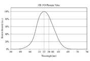
도 3은 사람의 시감 특성을 나타내는 그래프이다.
도 4는 본 발명의 황색 발광 형광체의 여기 스펙트럼을 나타내는 그래프이다.
도 5는 본 발명의 황색 발광 형광체의 발광 스펙트럼을 나타내는 그래프이다.
도 6은 본 발명의 황색 발광 형광체를 이용하여 백색 발광 소자 패키지를 구현한 경우의 발광 스펙트럼을 나타내는 그래프이다.
도 7은 본 발명의 황색 발광 형광체가 이용된 발광 소자 패키지의 일례를 나타내는 단면도이다.
도 8은 본 발명의 황색 발광 형광체가 이용된 발광 소자 패키지의 다른 예를 나타내는 단면도이다.
도 9는 본 발명의 황색 발광 형광체를 이용하여 백색광이 구현되는 과정을 설명하기 위한 도 7의 일부 확대도이다.1 is a graph showing the XRD spectrum of Li-α-SiAlON.
2 is a graph showing the XRD spectrum of Ca-alpha -SiAlON.
Fig. 3 is a graph showing the visual acuity of a person.
4 is a graph showing the excitation spectrum of the yellow light-emitting fluorescent substance of the present invention.
5 is a graph showing the emission spectrum of the yellow light-emitting fluorescent substance of the present invention.
FIG. 6 is a graph showing the emission spectrum when the white light emitting device package is implemented using the yellow light emitting phosphor of the present invention.
7 is a cross-sectional view showing an example of a light emitting device package using the yellow light emitting fluorescent material of the present invention.
8 is a cross-sectional view showing another example of a light emitting device package using the yellow light emitting phosphor of the present invention.
9 is a partial enlarged view of FIG. 7 for explaining the process of realizing white light using the yellow light-emitting fluorescent material of the present invention.
이하, 첨부된 도면을 참고하여 본 발명에 의한 실시예를 상세히 설명하면 다음과 같다.Hereinafter, embodiments of the present invention will be described in detail with reference to the accompanying drawings.
본 발명이 여러 가지 수정 및 변형을 허용하면서도, 그 특정 실시예들이 도면들로 예시되어 나타내어지며, 이하에서 상세히 설명될 것이다. 그러나 본 발명을 개시된 특별한 형태로 한정하려는 의도는 아니며, 오히려 본 발명은 청구항들에 의해 정의된 본 발명의 사상과 합치되는 모든 수정, 균등 및 대용을 포함한다.While the invention is susceptible to various modifications and alternative forms, specific embodiments thereof are shown by way of example in the drawings and will herein be described in detail. Rather, the intention is not to limit the invention to the particular forms disclosed, but rather, the invention includes all modifications, equivalents and substitutions that are consistent with the spirit of the invention as defined by the claims.
층, 영역 또는 기판과 같은 요소가 다른 구성요소 "상(on)"에 존재하는 것으로 언급될 때, 이것은 직접적으로 다른 요소 상에 존재하거나 또는 그 사이에 중간 요소가 존재할 수도 있다는 것을 이해할 수 있을 것이다.It will be appreciated that when an element such as a layer, region or substrate is referred to as being present on another element "on," it may be directly on the other element or there may be an intermediate element in between .
비록 제1, 제2 등의 용어가 여러 가지 요소들, 성분들, 영역들, 층들 및/또는 지역들을 설명하기 위해 사용될 수 있지만, 이러한 요소들, 성분들, 영역들, 층들 및/또는 지역들은 이러한 용어에 의해 한정되어서는 안 된다는 것을 이해할 것이다.Although the terms first, second, etc. may be used to describe various elements, components, regions, layers and / or regions, such elements, components, regions, layers and / And should not be limited by these terms.
우선, 본 발명에 의한 황색 발광 형광체에 대하여 설명한다.First, the yellow light-emitting fluorescent substance according to the present invention will be described.
본 발명에 의하면 근 자외선 및 청색 여기원에 의한 여기 효율이 우수한 녹색 및 호박색(Amber; 이하, 앰버라 칭함) 형광체를 혼합하여 휘도가 높은 황색 광을 구현할 수 있다.According to the present invention, yellow light having high luminance can be realized by mixing green and amber (hereinafter referred to as amber) phosphors having excellent excitation efficiency by near ultraviolet and blue excitation sources.
이를 위하여, 본 발명에서 근 자외선 및 청색 여기광에 의한 발광 효율이 우수한 녹색(green)계열 형광체인 LuAG, SrSi2O2N2 및 β형 SiAlON(사이알론) 중 적어도 어느 하나를 포함하는 제1형광체를 이용할 수 있다.For this purpose, in the present invention, a first phosphor containing at least one of LuAG, SrSi2 O2 N2, and β-type SiAlON (sialon), which is a green-based phosphor excellent in luminous efficiency by near- A phosphor can be used.
이러한 제1형광체는 근 자외선 및 청색 여기광에 의하여 여기되어 녹색 파장 대역의 광을 발광할 수 있다. 이와 같은 제1형광체는 중심파장이 530 내지 550 nm의 대역에 위치할 수 있다.The first phosphor can be excited by the near ultraviolet light and the blue excitation light to emit light in the green wavelength band. The first phosphor may have a center wavelength in a range of 530 to 550 nm.
여기서, LuAG는 Lu3Al5O12:Ce의 화학식으로 알려져 있고, β형 SiAlON은 Si6-zAlzOzN8-z의 기본 구조식에 Eu가 첨가된 화학식으로 표현될 수 있다. 이 외에도 LSN(La3Si6N11:Ce), SrSi2O2N2:Eu 형광체가 이용될 수 있다.Here, LuAG is known as the formula of Lu3 Al5 O12 : Ce, and β-type SiAlON can be represented by the formula in which Eu is added to the basic structure of Si6-z Alz Oz N8-z . In addition, LSN (La3 Si6 N11 : Ce) and SrSi2 O2 N2 : Eu phosphors may be used.
또한, 시감 특성이 우수하며, 제1형광체와 혼합되어 높은 휘도의 황색 광을 발광할 수 있는 최적의 발광 파장을 가지는 새로운 조성의 제2형광체를 포함할 수 있다. 이러한 제2형광체는 근 자외선 및 청색 여기광에 의하여 여기되어 앰버 파장 대역의 광을 발광할 수 있다.In addition, the phosphor may include a second phosphor having a new composition having an excellent luminosity characteristic and having an optimal emission wavelength capable of emitting yellow light of high luminance mixed with the first phosphor. Such a second phosphor can be excited by the near ultraviolet light and the blue excitation light to emit light in the amber wavelength band.
이와 같은 제1형광체 및 제2형광체의 혼합물은, 근 자외선 또는 청색 광에 의하여 여기되어 높은 휘도의 황색 광을 발광할 수 있다. 또한, 이러한 근 자외선 또는 청색 광에서 여기율이 우수하여 고 효율의 형광체 특성을 발휘할 수 있다.Such a mixture of the first phosphor and the second phosphor can be excited by near ultraviolet light or blue light to emit yellow light of high luminance. Further, the excitation ratio is excellent in such near ultraviolet light or blue light, and high-efficiency phosphor characteristics can be exhibited.
이러한 제2형광체는 리튬(Li)을 금속성분으로 가지는 α형 SiAlON(Li-α-SiAlON)을 포함할 수 있고, 근 자외선 또는 청색 광에 의하여 여기되어 중심파장이 550 내지 590 nm 대역에 위치하는 광을 발광할 수 있다.Such a second fluorescent material may include? -Type SiAlON (Li-? -SiAlON) having lithium (Li) as a metal component and may be excited by near ultraviolet light or blue light to have a center wavelength in the range of 550 to 590 nm Light can be emitted.
이러한 제2형광체는 아래의 화학식 1로 표현될 수 있다.The second phosphor may be represented by the following formula (1).

이러한 제2형광체는 보통 금속성분으로 Ca을 가지는 α형 SiAlON (Ca0.3Si9Al3O1N15)(Ca-α-SiAlON)에서 금속성분을 Li로 치환된 형광체(Li-α-SiAlON)로 볼 수 있다. 도 1에서는 이러한 Li-α-SiAlON의 XRD 스펙트럼을 나타내고 있고, 도 2에서는 Ca-α-SiAlON의 XRD 스펙트럼을 나타내고 있다. 따라서 본 발명에서 이용되는 Li-α-SiAlON은 Ca-α-SiAlON과 다른 특성을 가질 수 있다.Such a second phosphor is α-typeSiAlON (Ca 0.3 Si 9 Al 3 O 1 N 15) (Ca-α-SiAlON) the fluorescent substance (Li-α-SiAlON) replacing the metal with Li in having the Ca in the normal metal component Can be seen as. FIG. 1 shows the XRD spectrum of Li-α-SiAlON, and FIG. 2 shows the XRD spectrum of Ca-α-SiAlON. Therefore, Li -? - SiAlON used in the present invention may have properties different from those of Ca -? - SiAlON.
금속성분으로 Ca을 가지는 α형 SiAlON은 발광 중심파장이 600 nm 정도이나, 위에서 설명한 바와 같이, 중심파장이 550 내지 590 nm 대역인 Li-α-SiAlON을 이용하면 동일한 피크 세기를 가지는 발광에 대하여 시감 특성이 25 % 정도 높아질 수 있다. 더 좋게는 중심 파장이 578 내지 588 nm 대역에 위치하는 광을 발광하도록 하면 시감 특성은 더 향상될 수 있다.The? -Type SiAlON having Ca as a metal component has a luminescent center wavelength of about 600 nm. However, when Li -? - SiAlON having a central wavelength of 550 to 590 nm is used as described above, The characteristic can be increased by 25%. And more preferably, the center wavelength is made to emit light located in the 578 to 588 nm band, the luminosity characteristic can be further improved.
도 3은 사람의 시감(視感) 특성을 나타내는 그래프(Photonic curve)이다.3 is a photonic curve showing a person's visual acuity characteristic.
도시하는 바와 같이, 사람의 시감도의 값은 대략 555 nm 파장에서 최대값을 가진다. 즉, 동일한 강도의 빛에 대하여 사람은 555 nm 파장 대역의 빛을 가장 강한 것으로 감지한다.As shown, the value of human visibility has a maximum at a wavelength of approximately 555 nm. That is, for light of the same intensity, one perceives light in the 555 nm wavelength band as the strongest.
따라서, 통상 600 nm 정도의 발광 중심파장을 가지는 α형 SiAlON에 비하여, 본 발명에서 이용되는 중심파장이 550 내지 590 nm 대역인 Li-α-SiAlON은 시감 특성에서 우수할 수 있다.Therefore, Li-α-SiAlON having a central wavelength of 550 to 590 nm, which is used in the present invention, is superior to the? -Type SiAlON having a luminescence center wavelength of about 600 nm, which is superior to the visual sensitivity.
즉, 동일한 강도의 빛에 대하여 보다 밝게 감지할 수 있으므로, 이와 같은 발광 파장의 조절은 휘도가 증가하는 효과로 작용할 수 있다.That is, since the light of the same intensity can be detected more brighter, the adjustment of the emission wavelength can act as an effect of increasing the luminance.
이와 같은 본 발명의 제2형광체로 이용될 수 있는 Li-α-SiAlON은, 동일한 피크 세기의 발광에 대하여 Ca-α-SiAlON에 비하여 시감 특성이 25 % 정도 향상될 수 있다.The Li-α-SiAlON which can be used as the second phosphor of the present invention can improve the luminous characteristic by about 25% as compared with Ca- α-SiAlON for the emission of the same peak intensity.
본 발명에서는 중심 파장이 550 내지 590 nm 대역인 발광을 구현하기 위하여 SiAlON 합성시 Li의 치환량을 조절하고 산소(Oxygen)의 양을 조절할 수 있다.In the present invention, in order to realize light emission having a center wavelength of 550 to 590 nm, it is possible to control the substitution amount of Li and the amount of oxygen during SiAlON synthesis.
표 1은 이러한 제2형광체 구현시 산소의 함량(n; 화학식1에서의 값)을 조절하여 얻은 형광체의 발광 파장(피크 파장) 및 발광 휘도를 나타내고 있다.Table 1 shows the emission wavelength (peak wavelength) and the emission luminance of the phosphor obtained by adjusting the content of oxygen (n: the value in Chemical Formula 1) in the implementation of the second phosphor.
이러한 발광을 위하여 화학식 1에서 m 및 n은, 0 ≤ m ≤ 2 및 0 ≤ n ≤ 1 중 적어도 하나의 조건을 만족할 수 있다. 또한, 화학식 1에서 x는 활성제(Eu)의 함량을 나타내며, 금속 이온(리튬(Li) 및 알루미늄(Al))과 10% 이내의 범위에서 치환되는 것이 보통이다. 즉, x는 0.01 내지 0.1 사이의 값을 가질 수 있다.For such luminescence, m and n in formula (1) may satisfy at least one of 0? M? 2 and 0? N? 1. In the general formula (1), x represents the content of the activator (Eu), and it is usually substituted within 10% with metal ions (lithium (Li) and aluminum (Al)). That is, x may have a value between 0.01 and 0.1.

표 1에서 나타내는 바와 같이, 제2형광체의 산소(Oxygen)의 함량에 따라 발광 파장이 변경될 수 있음을 알 수 있다. 즉, 산소(Oxygen)의 함량(n)이 0인 경우에 588 nm의 발광 파장을 가지고 이때의 발광 휘도는 95%를 가짐을 알 수 있고, 산소의 함량(n)이 1인 경우, 발광 파장은 578 nm까지 낮아질 수 있음을 알 수 있다.As shown in Table 1, it can be seen that the emission wavelength can be changed depending on the content of oxygen (Oxygen) in the second phosphor. That is, when the content (n) of oxygen is 0, the emission wavelength is 588 nm and the emission luminance at this time is 95%. When the content (n) of oxygen is 1, Lt; RTI ID = 0.0 > 578 nm. ≪ / RTI >
그리고 추가적인 시감 특성을 통한 발광효율 개선을 위해 산소(Oxygen)의 함량(n)을 1 ≤ n ≤ 2 사이로 변화시킬 경우, 발광파장을 560 nm까지 변화시키는 것이 가능하다. 이와 같이, 산소의 함량을 조정함에 따라 발광 파장을 단파장으로 이동하는 것이 용이할 수 있다.When the content (n) of oxygen is changed to 1? N? 2 in order to improve the luminous efficiency through the additional luminosity characteristic, it is possible to change the emission wavelength to 560 nm. Thus, it is easy to shift the emission wavelength to a short wavelength by adjusting the content of oxygen.
표 1에서 보면 산소(Oxygent)의 함량(n)이 0.1이고 발광파장이 583 nm일 때 발광 휘도가 가장 높음을 알 수 있다.Table 1 shows that the emission luminance is highest when the content (n) of oxygen (oxygent) is 0.1 and the emission wavelength is 583 nm.
이상에서 설명한 바와 같이, 본 발명에서는 녹색 발광 형광체인 제1형광체와 앰버 색상 발광 형광체인 제2형광체를 혼합하여 휘도가 우수한 황색 광을 구현할 수 있다.As described above, in the present invention, the first phosphor as the green light emitting phosphor and the second phosphor as the amber color light emitting phosphor are mixed to realize yellow light having excellent brightness.
또한, 제1형광체 및 제2형광체 각각의 발광 파장 및 혼합 비율을 조절함으로써 발광 휘도를 향상시킬 수 있다. 이와 함께 광원의 연색성을 나타내는 연색 평가 지수(color rendering index; CRI)가 함께 개선될 수 있다.Further, by adjusting the emission wavelength and mixing ratio of each of the first phosphor and the second phosphor, the emission luminance can be improved. In addition, the color rendering index (CRI) indicating the color rendering property of the light source can be improved together.
이러한 연색 평가 지수(CRI)는 광원의 연색성을 나타내는 것을 목적으로 한 지수로서 시료 광원 아래에서 물체의 색 지각이 규정된 기준 광 아래서 동일한 물체의 색 지각에 합치되는 정도를 수치화한 것이다.The color rendering index (CRI) is an index for indicating the color rendering property of a light source, and is a numerical value indicating the degree to which the color perception of the object under the sample light source matches the color perception of the same object under the reference light prescribed.
표 2는 이와 같이 제1형광체와 앰버 색상 발광 형광체인 제2형광체를 혼합하여 휘도 및 CRI가 향상될 수 있음을 나타내고 있다.Table 2 shows that the luminance and the CRI can be improved by mixing the first phosphor and the second phosphor as the amber color light emitting phosphor as described above.

즉, 종래의 황색 형광체(Yellow 형광체; 통상적으로 많이 사용되는 YAG 형광체를 나타낸다.)와 Ca-α-SiAlON를 이용하여 황색 발광 형광체를 구현한 것에 대비하여, 본 발명의 제1형광체(535 nm 피크 파장을 갖는 경우) 및 제2형광체(583 nm 피크 파장을 갖는 경우)를 사용함으로써 발광 휘도 및 CRI가 종래의 황색 형광체에 비하여 향상될 수 있음을 알 수 있다.That is, in contrast to the implementation of a yellow light-emitting phosphor using a conventional yellow phosphor (yellow phosphor, commonly used YAG phosphor) and Ca-? -SiAlON, the first phosphor of the present invention It can be seen that the light emission luminance and the CRI can be improved as compared with the conventional yellow phosphor by using the second phosphor (in the case of having a wavelength) and the second phosphor (in the case of having a peak wavelength of 583 nm).
<실시예><Examples>
표 3은 제1형광체로서 535 nm의 녹색(green) 파장(피크 파장) 대역의 광을 발광하는 LuAG 형광체를 이용하고, 제2형광체로서 583 nm의 앰버(Amber) 색상 파장(피크 파장) 대역의 광을 발광하는 Li-α-SiAlON을 혼합하여 황색 발광 형광체를 구현한 예를 나타내고 있다.Table 3 shows that the LuAG phosphor emitting light in the green wavelength band (peak wavelength) of 535 nm as the first phosphor and the LuAG phosphor emitting light in the Amber color wavelength (peak wavelength) band of 583 nm And Li -? - SiAlON which emits light are mixed to realize a yellow light emitting phosphor.
(100%)535nm Green
(100%)
(0%)583 nm Amber
(0%)
(90%)535nm Green
(90%)
(10%)583 nm Amber
(10%)
(80%)535nm Green
(80%)
(20%)583 nm Amber
(20%)
(70%)535nm Green
(70%)
(30%)583 nm Amber
(30%)
(60%)535nm Green
(60%)
(40%)583 nm Amber
(40%)
(50%)(50%)
(50%)(50%)
(40%)535nm Green
(40%)
(60%)583 nm Amber
(60%)
(30%)535nm Green
(30%)
(70%)583 nm Amber
(70%)
(20%)535nm Green
(20%)
(80%)583 nm Amber
(80%)
(10%)535nm Green
(10%)
(90%)583 nm Amber
(90%)
(0%)535nm Green
(0%)
(100%)583 nm Amber
(100%)
이러한 예에서, 제1형광체와 제2형광체의 함량을 각각 0 내지 100 wt%로 조절하면서 각각의 경우의 색좌표, CRI 및 발광 휘도를 측정한 결과가 표 3에 나타나 있다. 즉, 제1형광체가 100 wt%이고 제2형광체가 0 wt%인 경우부터 제1형광체가 0 wt%이고 제2형광체가 100 wt%인 경우를 순차적으로 나타내고 있다. 여기서 함량(%)은 중량%(wt%)를 나타낸다.In this example, the results of measuring the color coordinates, CRI, and luminescence brightness in each case while controlling the contents of the first and second phosphors to 0 to 100 wt% are shown in Table 3. That is, the cases where the first phosphor is 0 wt% and the second phosphor is 100 wt% are sequentially shown from when the first phosphor is 100 wt% and the second phosphor is 0 wt%. Here, the content (%) represents the weight% (wt%).
비교가 되는 황색 형광체(Yellow)는 YAG 형광체의 예를 나타내고 있으며, 이러한 YAG 형광체는 색좌표가 CIE x 및 CIE y가 각각 0.454 및 0.531이고, CRI가 36.5인 것을 알 수 있다. 이때, YAG 형광체의 발광 휘도를 100으로 설정한 경우를 나타내고 있다.The yellow phosphor to be compared is an example of a YAG fluorescent material. It can be seen that the YAG fluorescent material has CIE x and CIE y of 0.454 and 0.531, respectively, and a CRI of 36.5. At this time, the case where the light emission luminance of the YAG fluorescent material is set to 100 is shown.
표 3에서 나타내는 바와 같이, 본 발명의 황색 형광체는 종래의 황색 형광체에 비하여 대부분의 경우에 발광 휘도가 향상됨을 알 수 있다. 발광 휘도는 제1형광체의 함량이 증가함에 따라 대체적으로 증가하는 경향을 보이고 있다.As shown in Table 3, the yellow phosphor of the present invention shows improved luminescence brightness in most cases compared with the conventional yellow phosphor. The luminescence brightness generally tends to increase as the content of the first phosphor increases.
또한, CRI의 경우에는 제1형광체가 60 wt%이고 제2형광체가 40 wt%인 경우부터 종래의 황색 형광체에 비하여 향상됨을 알 수 있다. 이러한 CRI의 경우에는 제2형광체의 함량이 증가함에 따라 대체적으로 증가하는 경향을 보이고 있다.Further, in the case of CRI, it can be seen that from the case where the first phosphor is 60 wt% and the second phosphor is 40 wt%, it is improved as compared with the conventional yellow phosphor. In the case of this CRI, the content of the second phosphor tends to increase as the content of the second phosphor increases.
이러한 CRI 및 발광 휘도와 관련된 결과를 고려할 때, 제1형광체 및 제2형광체의 비율이 60 wt% 대 40 wt%(6:4)에서 40 wt% 대 60 wt%(4:6) 사이의 비율을 가지는 경우에 그 효과가 가장 우수함을 알 수 있다.Considering the results related to the CRI and the emission luminance, the ratio of the first phosphor and the second phosphor is changed from 60 wt% to 40 wt% (6: 4) to 40 wt% to 60 wt% (4: 6) It can be seen that the effect is the most excellent.
즉, 제2형광체는, 제1형광체 및 제2형광체의 합을 100 wt%로 했을 때, 40 내지 60 wt%의 함량을 가질 수 있다.That is, the second phosphor may have an amount of 40 to 60 wt%, assuming that the sum of the first phosphor and the second phosphor is 100 wt%.
이 중에서도 제1형광체 및 제2형광체의 비율이 50 wt% 대 50 wt%(5:5)인 경우에는 CRI 및 발광 휘도를 종합할 때 황색 발광 형광체로서 가장 특성이 우수하다고 할 수 있다.Among them, when the ratio of the first phosphor and the second phosphor is 50 wt% to 50 wt% (5: 5), the most excellent characteristic of the yellow light emitting phosphor is obtained when the CRI and the emission luminance are combined.
도 4는 본 발명의 황색 발광 형광체의 여기 스펙트럼을 나타내는 그래프이다. 이러한 스펙트럼은 본 발명의 황색 발광 형광체가 여기되는 파장 대역 및 해당 파장에서의 여기의 정도를 나타내고 있다.4 is a graph showing the excitation spectrum of the yellow light-emitting fluorescent substance of the present invention. This spectrum shows the wavelength band in which the yellow light-emitting fluorescent substance of the present invention is excited and the degree of excitation at the wavelength.
도 4에서 도시하는 바와 같이, 본 발명의 황색 발광 형광체는 점선으로 표시된 종래의 황색 발광 형광체(Yellow; 일례로서, YAG 형광체)에 비하여 단파장에서의 여기 정도가 우수함을 알 수 있다.As shown in FIG. 4, the yellow light-emitting fluorescent substance of the present invention is superior to the conventional yellow light-emitting fluorescent substance (Yellow, for example, YAG fluorescent substance) indicated by a dotted line in excitation degree at a short wavelength.
예를 들어, 여기 파장이 410 nm인 경우, 여기 정도가 470 nm 근처의 피크 강도에 비하여 대략 절반 정도(절반 이상)로 유지되는 것을 볼 수 있다.For example, if the excitation wavelength is 410 nm, the degree of excitation can be seen to be about half (about half or more) compared with the peak intensity near 470 nm.
즉, 본 발명의 황색 발광 형광체의 여기 스펙트럼은, 410 nm 파장에서 피크 대비 50 % 이상의 여기율을 가질 수 있다.That is, the excitation spectrum of the yellow light-emitting phosphor of the present invention may have an excitation ratio of 50% or more with respect to the peak at a wavelength of 410 nm.
또한, 410 nm보다 단파장에서도 여기 정도가 크게 감소하지 않는 것을 알 수 있다. 즉, 400 nm 파장에서도 410 nm와 유사한 정도의 여기율을 보임을 알 수 있다.In addition, it can be seen that the degree of excitation does not significantly decrease even at a shorter wavelength than 410 nm. That is, it can be seen that the excitation ratio is similar to 410 nm even at the wavelength of 400 nm.
즉, 본 발명의 황색 발광 형광체의 여기 스펙트럼은, 450 nm 이하의 파장 대역에서 YAG 형광체보다 높은 여기율을 가질 수 있다.That is, the excitation spectrum of the yellow light-emitting fluorescent substance of the present invention can have a higher excitation ratio than the YAG fluorescent substance in the wavelength band of 450 nm or less.
형광체를 여기시키는 근자외선 또는 청색 광은 단파장으로 갈수록 우수한 여기광을 보이므로, 이와 같이, 단파장 대역에서 여기 정도가 우수한 본 발명은 형광체로서의 특성이 상대적으로 우수함을 알 수 있다.The near ultraviolet or blue light that excites the phosphor exhibits excellent excitation light toward shorter wavelengths. Thus, it can be seen that the present invention having excellent excitation in a short wavelength band is relatively excellent in characteristics as a phosphor.
이는, 여기 광으로서 작용하는 근 자외선 또는 청색 광이 단파장으로 갈수록 발광의 세기 및 발광 품질 등이 우수한 경향을 보이고 있고, 이러한 근 자외선 또는 청색 광을 발광하는 발광 소자(예를 들어, LED)가 고출력화 됨에 따라 중심 파장이 450 nm 이하로 이동하는 경향을 보이고 있기 때문이다.This is because a near-ultraviolet or blue light acting as an excitation light tends to have an excellent intensity of light emission and a luminescent quality as it goes to a short wavelength, and a light emitting device (for example, LED) emitting such near- The center wavelength shifts to 450 nm or less.
예를 들어, 점선으로 표시된 황색 발광 형광체는 단파장으로 갈수록 여기 정도가 눈에 띄게 감소함을 알 수 있고, 이는 여기광을 발산하는 발광 소자가 고출력화됨에 따라 광 변환 효율이 낮아짐을 알 수 있다.For example, it can be seen that the yellow light emitting phosphor indicated by the dotted line has a remarkably reduced excitation degree toward a shorter wavelength, and the light conversion efficiency is lowered as the light emitting device which emits the excitation light becomes higher output.
그러나, 본 발명의 황색 발광 형광체는 여기광을 발산하는 발광 소자가 고출력화 될수록 발광 특성이 더 향상될 수 있음을 알 수 있다.However, it can be seen that the luminescent characteristics of the yellow light-emitting fluorescent material of the present invention can be further improved as the light-emitting element which emits the excitation light becomes higher in output.
도 5는 본 발명의 황색 발광 형광체의 발광 스펙트럼을 나타내는 그래프이다.5 is a graph showing the emission spectrum of the yellow light-emitting fluorescent substance of the present invention.
본 발명의 황색 발광 형광체는 녹색 발광과 앰버 발광의 혼합 광으로서 황색을 구현할 수 있으며, 도 5에서 실선으로 나타난 본 발명의 황색 광의 스펙트럼은 점선으로 표기된 종래의 황색 광(Yellow)보다 파장 대역 및 발광 강도가 우수함을 알 수 있다.The yellow light emitting phosphor of the present invention can realize yellow as mixed light of green light emission and amber light emission, and the spectrum of the yellow light of the present invention shown by the solid line in FIG. 5 has wavelength band and light emission It can be seen that the strength is excellent.
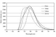
도 6은 본 발명의 황색 발광 형광체를 이용하여 백색 발광 소자 패키지를 구현한 경우의 발광 스펙트럼을 나타내는 그래프이다.FIG. 6 is a graph showing the emission spectrum when the white light emitting device package is implemented using the yellow light emitting phosphor of the present invention.
도 6에서 도시하는 바와 같이, 청색 여기광 및 이 청색광에 의하여 본 발명에 의한 황색 발광 형광체가 여기되어 발광한 황색광이 혼합되어 우수한 품질의 백색 광을 발산할 수 있음을 알 수 있다.As shown in FIG. 6, it can be seen that yellow light emitted by the excitation of the yellow light-emitting phosphor according to the present invention by the blue excitation light and the blue light are mixed with each other to emit white light of excellent quality.
즉, 본 발명의 황색 발광 형광체(Green + 583 nm Amber)는 종래의 황색 발광 형광체(Yellow) 및 아래에서 설명하는 비교예(Green + 600 nm Amber)에 비하여 향상된 광의 특성을 보이고 있다.That is, the yellow light-emitting phosphor of the present invention (Green + 583 nm Amber) exhibits improved light characteristics compared to the conventional yellow light-emitting phosphor (Yellow) and the comparative example (Green + 600 nm Amber) described below.
이와 같이, 황색 발광 대역에서 광의 강도 및 시감도가 우수하여, 근자외선 또는 청색 발광 소자와 함께 고 품질의 백색 광을 만들어낼 수 있다.Thus, the light intensity and visibility in the yellow light emitting band are excellent, and high-quality white light can be produced together with the near-ultraviolet light or the blue light emitting element.
<비교예><Comparative Example>
표 4는 535 nm의 녹색 파장(피크 파장) 대역의 광을 발광하는 LuAG 형광체(이하, 녹색 형광체)와 600 nm의 앰버 색상 파장(피크 파장) 대역의 광을 발광하는 Ca-α-SiAlON(이하, 앰버 형광체)을 혼합하여 황색 발광 형광체를 구현한 예를 나타내고 있다.Table 4 shows the emission spectra of a LuAG phosphor (hereinafter referred to as a green phosphor) emitting light in a green wavelength (peak wavelength) band of 535 nm and Ca- alpha -SiAlON , An amber phosphor) are mixed to realize a yellow light-emitting phosphor.
(100%)535nm Green
(100%)
(0%)600nm Amber
(0%)
(90%)535nm Green
(90%)
(10%)600nm Amber
(10%)
(80%)535nm Green
(80%)
(20%)600nm Amber
(20%)
(70%)535nm Green
(70%)
(30%)600nm Amber
(30%)
(60%)535nm Green
(60%)
(40%)600nm Amber
(40%)
(50%)(50%)
(50%)(50%)
(40%)535nm Green
(40%)
(60%)600nm Amber
(60%)
(30%)535nm Green
(30%)
(70%)600nm Amber
(70%)
(20%)535nm Green
(20%)
(80%)600nm Amber
(80%)
(10%)535nm Green
(10%)
(90%)600nm Amber
(90%)
(0%)535nm Green
(0%)
(100%)600nm Amber
(100%)
이러한 예에서는, 표 3의 경우와 유사하게, 녹색(green) 형광체와 앰버(Amber) 형광체의 함량을 각각 0 내지 100 wt%로 조절하면서 각각의 경우의 색좌표, CRI 및 발광 휘도를 측정한 결과가 표 4에 나타나 있다. 또한, 비교가 되는 황색 형광체(Yellow 형광체)는 YAG 형광체의 예를 나타내고 있다. 여기서 함량(%)은 중량%(wt%)를 나타낸다.In this example, similarly to the case of Table 3, the results of measuring the color coordinates, CRI and emission luminance of each case while controlling the contents of the green phosphor and the amber phosphor to 0 to 100 wt% It is shown in Table 4. The yellow phosphor to be compared (Yellow phosphor) is an example of a YAG phosphor. Here, the content (%) represents the weight% (wt%).
표 4에서 나타내는 바와 같이, 비교예로서의 황색 형광체는 종래의 황색 형광체에 비하여 CRI 특성은 상대적으로 우수하나 발광 휘도가 저하됨을 알 수 있다. 또한, 발광 휘도가 우수한 구간에서는 CRI가 저하됨을 볼 수 있다.As shown in Table 4, it can be seen that the yellow phosphor as a comparative example has a CRI characteristic relatively higher than that of the conventional yellow phosphor, but the luminescence brightness is lowered. Further, it can be seen that the CRI is lowered in the section where the luminescence brightness is excellent.
<발광 소자 패키지>≪ Light emitting device package &
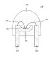
도 7은 본 발명의 황색 발광 형광체가 이용된 발광 소자 패키지의 일례를 나타내는 단면도이다. 도 7은 본 발명의 일 실시 예에 따른 램프형의 발광 소자 패키지(100)의 예를 나타내고 있다.7 is a cross-sectional view showing an example of a light emitting device package using the yellow light emitting fluorescent material of the present invention. FIG. 7 shows an example of a lamp-type light emitting
이러한 램프형의 백색 발광 소자 패키지(100)는 한 쌍의 리드 프레임(110, 120)과, 전압의 인가에 따라 빛을 발생시키는 발광 소자(130)를 포함한다.The lamp-type white light emitting
발광 소자(130)는 리드 프레임(110, 120)과 와이어(140)에 의하여 전기적으로 연결되고, 발광 소자(130) 상에는 광 투과성 수지(150)가 몰딩된다. 이러한 발광 소자(130)는 근 자외선 또는 청색 광을 발광할 수 있다.The
또한, 근 자외선 발광 소자 대신 동일한 파장 영역에 주 발광 피크를 가지는 발광 소자로서, 레이저 다이오드, 면 발광 레이저 다이오드, 무기 전계 발광 소자, 유기 전계 발광 소자 등을 사용할 수도 있다. 본 발명에서는 바람직한 응용 예로서 질화물 반도체 발광 다이오드가 이용되는 예를 나타내고 있다. 도 7에서 발광 소자(130)는 개략적으로 표현되고 있으며, 수평형 또는 수직형 질화물 반도체 발광 다이오드가 모두 이용될 수 있다.Further, a laser diode, a surface-emission laser diode, an inorganic electroluminescent element, an organic electroluminescent element, or the like may be used as a light emitting element having a main emission peak in the same wavelength region instead of the near ultraviolet light emitting element. In the present invention, as a preferred application example, a nitride semiconductor light emitting diode is used. In FIG. 7, the
이러한 광 투과성 수지(150)에는 형광체(170, 171; 도 9 참고)가 분산되어 구비될 수 있고, 광 투과성 수지(150) 상에는 소자 전체의 외부 공간을 마감하는 외장재(160)가 구비될 수 있다.The
여기서 사용되는 형광체(170, 171)는 위에서 설명한 제1형광체(170) 및 제2형광체(171)를 포함하는 황색 발광 형광체 이외에 다른 형광체, 예를 들면 적색 발광 형광체(172)가 함께 분산되어 구비될 수 있다. 이러한 분산 형광체(172)는 경우에 따라 두 종류 이상이 구비될 수 있다.The
몰딩 부재로 사용되는 광 투과 수지(150)는 광 투과 에폭시 수지, 실리콘 수지, 폴리이미드 수지, 요소 수지, 아크릴 수지 등이 사용될 수 있다. 바람직하게는 광 투과 에폭시 수지 또는 광 투과 실리콘 수지 등이 사용될 수 있다.As the
본 실시예의 광 투과성 수지(150)도 발광 소자(130) 주위를 전체적으로 몰딩 할 수도 있지만 필요에 따라 발광 부위에 부분적으로 몰딩되어 구비될 수도 있다.The
즉, 고출력 발광 소자의 경우에는 발광 소자(130)의 대형화로 인해 전체적으로 몰딩할 경우, 광 투과성 수지(150)에 분산되는 형광체(170, 171)의 균일 분산에 불리할 수 있기 때문이다. 이 경우 발광 부위에 부분적으로 몰딩하는 것이 유리할 수 있다.That is, in the case of a high output light emitting device, uniform molding of the
도 8은 본 발명의 황색 발광 형광체가 이용된 발광 소자 패키지의 다른 예를 나타내는 단면도이다. 도 8은 표면 실장 형 발광 소자 패키지(200)를 나타내고 있다.8 is a cross-sectional view showing another example of the light emitting device package using the yellow light emitting phosphor of the present invention. 8 shows a surface-mounted light emitting
본 발명의 일 실시예에 따른 표면 실장 형 발광 소자 패키지(200)는 도 8에 도시된 바와 같이, 양극 및 음극의 리드 프레임(210, 220)이 구비되고, 이 양극 및 음극의 리드 프레임(210, 220) 중 어느 하나의 위에 위치하여 전압의 인가에 따라 빛을 발생시키는 발광 소자(240)를 포함한다. 이러한 발광 소자(240)는 발광 다이오드 또는 레이저 다이오드를 이용할 수 있다.8, the surface mount type light emitting
도 8에서는 수평형 구조를 가지는 발광 소자(240)의 예를 도시하고 있으나, 수직형 구조의 발광 소자가 이용될 수 있음은 물론이다.Although FIG. 8 shows an example of the
이러한 발광 소자(240)는 리드 프레임(210, 220)과 와이어(250)에 의하여 전기적으로 연결되고, 발광 소자(240) 상에는 광 투과성 수지(260)가 몰딩된다. 이러한 리드 프레임(210, 220)은 패키지 몸체(230)에 의하여 고정될 수 있고, 패키지 몸체(230)는 반사컵 형상을 제공할 수 있다.The
또한, 이러한 광 투과성 수지(260)에는 형광체(270, 271)가 분산되어 구성될 수 있다.Further, the light-transmitting
여기에 사용되는 형광체(270, 271)는 위에서 설명한 제1형광체(270) 및 제2형광체(271)가 혼합되어 분산되어 사용될 수 있으며, 이외에 다른 형광체가 함께 분산되어 구비될 수 있다. 예를 들면 적색 발광 형광체(272)가 함께 분산되어 구비될 수 있다. 이러한 분산 형광체(272)는 경우에 따라 두 종류 이상이 구비될 수 있다.The
몰딩 부재로 사용되는 광 투과성 수지(260)는 광 투과 에폭시 수지, 실리콘 수지, 폴리이미드 수지, 요소 수지, 아크릴 수지 등이 사용될 수 있다. 바람직하게는 광 투과 에폭시 수지 또는 광 투과 실리콘 수지 등이 사용될 수 있다.As the
이러한 광 투과성 수지(260)는 발광 소자(120) 주위를 전체적으로 몰딩할 수도 있지만 필요에 따라 발광 부위에 부분적으로 몰딩하는 것도 가능하다.The
그 외에 설명되지 않은 부분은 도 7을 참조하여 설명한 사항과 동일한 사항이 적용될 수 있다.
The same elements as those described with reference to Fig.
위에서 상세히 설명한 본 발명에 따른 발광 소자 패키지(100, 200)는 백색 발광 패키지로 구현될 수 있다.The light emitting
도 9는 도 7의 일부 확대도로서, 도 8을 함께 참조하여 백색광이 구현되는 과정을 설명하면 다음과 같다.FIG. 9 is a partially enlarged view of FIG. 7. Referring to FIG. 8 together, the process of realizing white light will be described below.
발광 소자(120, 220)에서 출사되는 근 자외선 또는 청색 광에 해당하는 400 내지 480 nm 파장 영역의 푸른 빛이 형광체(170, 171, 270, 271)를 통과하게 된다. 여기에 일부 빛은 형광체(170, 171, 270, 271)를 여기시켜 도 6에서 도시하는 바와 같은 발광 파장 중심이 500 내지 600 nm 범위의 주요 피크를 갖는 광을 발생시키고, 나머지 빛은 푸른 빛으로 그대로 투과시킨다.Blue light in a wavelength range of 400 to 480 nm corresponding to near-ultraviolet light or blue light emitted from the
그 결과, 400 내지 700 nm의 넓은 파장의 스펙트럼을 갖는 백색광을 발광하게 된다.As a result, white light having a spectrum of a wide wavelength of 400 to 700 nm is emitted.
형광체(170, 171, 270, 271)는 위에서 설명한 산 질화물 형광체 이외에 다른 형광체가 함께 분산되어 구비될 수 있다.The
예를 들어, 이들 형광체(170, 171, 270, 271)는 위에서 설명한 황색 발광 형광체 외에 다른 발광 피크를 가지는 형광체(제3형광체)가 혼합되어 함께 이용될 수 있다.For example, the
한편, 본 명세서와 도면에 개시된 본 발명의 실시 예들은 이해를 돕기 위해 특정 예를 제시한 것에 지나지 않으며, 본 발명의 범위를 한정하고자 하는 것은 아니다. 여기에 개시된 실시 예들 이외에도 본 발명의 기술적 사상에 바탕을 둔 다른 변형 예들이 실시 가능하다는 것은, 본 발명이 속하는 기술 분야에서 통상의 지식을 가진 자에게 자명한 것이다.It should be noted that the embodiments of the present invention disclosed in the present specification and drawings are only illustrative of specific examples for the purpose of understanding and are not intended to limit the scope of the present invention. It will be apparent to those skilled in the art that other modifications based on the technical idea of the present invention are possible in addition to the embodiments disclosed herein.
100, 200: 발광 소자 패키지110, 120, 210, 220: 리드 프레임
130, 240: 발광 소자 140, 250: 와이어
150, 260: 광 투과 수지160: 외장재
170, 171, 172, 270, 271, 272: 형광체
230: 패키지 몸체100, 200: light emitting
130, 240: light emitting
150, 260: light transmitting resin 160: exterior material
170, 171, 172, 270, 271, 272: phosphors
230: package body
Claims (15)
Translated fromKoreanLu3Al5O12:Ce, SrSi2O2N2 및 β형 SiAlON 중 적어도 어느 하나를 포함하는 제1형광체; 및
상기 제1형광체와 혼합되어 혼합물을 이루며, Li을 금속성분으로 가지는 α형 SiAlON(Li-α-SiAlON)을 포함하고, 근 자외선 또는 청색 광에 의하여 여기되어 중심파장이 550 내지 590 nm 대역에 위치하는 광을 발광하는 제2형광체를 포함하여 구성되고,
상기 제1형광체 및 제2형광체의 혼합물은, 상기 근 자외선 또는 청색 광에 의하여 여기되어 황색 광을 발광하는 것을 특징으로 하는 황색 발광 형광체.In the yellow light-emitting phosphor,
A first phosphor comprising at least one of Lu3 Al5 O12 : Ce, SrSi2 O2 N2 and β-type SiAlON; And
SiAlON (Li -? - SiAlON) having Li as a metal component mixed with the first phosphor to form a mixture and is excited by near ultraviolet light or blue light and has a center wavelength in a range of 550 to 590 nm And a second phosphor that emits light to emit light,
Wherein the mixture of the first phosphor and the second phosphor is excited by the near ultraviolet light or the blue light to emit yellow light.
<화학식 1>

상기 m 및 n은, 0 ≤ m ≤ 2 및 0 ≤ n ≤ 1 중 적어도 하나의 조건을 만족하는 것을 특징으로 하는 황색 발광 형광체.The phosphor according to claim 1, wherein the second phosphor is expressed by the following formula (1)
≪ Formula 1 >
Wherein m and n satisfy at least one of 0? M? 2 and 0? N? 1.
중심파장이 530 내지 550 nm의 대역에 위치하는 광을 방출하는 제1형광체; 및
상기 제1형광체와 혼합되어 중심파장이 550 내지 590 nm 대역에 위치하는 광을 발광하는 것으로서, 하기의 화학식 1로 표현되고,
<화학식 1>

상기 m 및 n은, 0 ≤ m ≤ 2 및 0 ≤ n ≤ 1 중 적어도 하나의 조건을 만족하는 제2형광체를 포함하여 구성되는 것을 특징으로 하는 황색 발광 형광체.In the yellow light-emitting phosphor,
A first phosphor emitting light having a center wavelength in a range of 530 to 550 nm; And
And is mixed with the first phosphor to emit light having a center wavelength in the range of 550 to 590 nm,
≪ Formula 1 >
Wherein m and n each include a second phosphor that satisfies at least one of 0? M? 2 and 0? N? 1.
Lu3Al5O12:Ce, SrSi2O2N2 및 β형 SiAlON 중 적어도 어느 하나를 포함하는 제1형광체; 및
상기 제1형광체와 혼합되어 혼합물을 이루며, Li을 금속성분으로 가지는 α형 SiAlON(Li-α-SiAlON)을 포함하고, 근 자외선 또는 청색 광에 의하여 여기되어 중심파장이 578 내지 588 nm 대역에 위치하는 광을 발광하는 제2형광체를 포함하여 구성되고,
상기 제2형광체는, 상기 제1형광체 및 제2형광체의 합을 100 wt%로 했을 때, 40 내지 60 wt%의 함량을 가지고,
상기 제1형광체 및 제2형광체의 혼합물은, 상기 근 자외선 또는 청색 광에 의하여 여기되어 황색 광을 발광하는 것을 특징으로 하는 황색 발광 형광체.In the yellow light-emitting phosphor,
A first phosphor comprising at least one of Lu3 Al5 O12 : Ce, SrSi2 O2 N2 and β-type SiAlON; And
SiAlON (Li-α-SiAlON) having Li as a metal component mixed with the first phosphor to form a mixture and excited by near ultraviolet light or blue light to have a center wavelength in a range of 578 to 588 nm And a second phosphor that emits light to emit light,
Wherein the second phosphor has an amount of 40 to 60 wt% based on 100 wt% of the sum of the first phosphor and the second phosphor,
Wherein the mixture of the first phosphor and the second phosphor is excited by the near ultraviolet light or the blue light to emit yellow light.
상기 황색 발광 형광체를 여기시키는 근 자외선 또는 청색 여기 광을 발광하는 발광 소자를 포함하는 것을 특징으로 하는 발광 소자 패키지.The yellow light-emitting phosphor according to any one of claims 1, 8, and 14; And
And a light emitting element that emits near-ultraviolet light or blue excitation light that excites the yellow light-emitting fluorescent substance.
Priority Applications (6)
| Application Number | Priority Date | Filing Date | Title |
|---|---|---|---|
| KR1020140064384AKR101476217B1 (en) | 2014-05-28 | 2014-05-28 | Phosphor emitting yellow light and light emitting device package using the same |
| EP15001081.7AEP2949727B1 (en) | 2014-05-28 | 2015-04-15 | Yellow light emitting phosphor and light emitting device package using the same |
| JP2015094025AJP5956643B2 (en) | 2014-05-28 | 2015-05-01 | Yellow light emitting phosphor and light emitting device package using the same |
| US14/705,620US9475987B2 (en) | 2014-05-28 | 2015-05-06 | Yellow light emitting phosphor and light emitting device package using the same |
| TW104116852ATWI572694B (en) | 2014-05-28 | 2015-05-26 | Yellow-emitting phosphor and light-emitting device package using the same |
| CN201510279150.5ACN105295914A (en) | 2014-05-28 | 2015-05-27 | Yellow light emitting phosphor and light emitting device package using the same |
Applications Claiming Priority (1)
| Application Number | Priority Date | Filing Date | Title |
|---|---|---|---|
| KR1020140064384AKR101476217B1 (en) | 2014-05-28 | 2014-05-28 | Phosphor emitting yellow light and light emitting device package using the same |
Related Child Applications (1)
| Application Number | Title | Priority Date | Filing Date |
|---|---|---|---|
| KR1020140155340ADivisionKR102092676B1 (en) | 2014-11-10 | 2014-11-10 | Light emitting device |
Publications (1)
| Publication Number | Publication Date |
|---|---|
| KR101476217B1true KR101476217B1 (en) | 2014-12-24 |
Family
ID=52679865
Family Applications (1)
| Application Number | Title | Priority Date | Filing Date |
|---|---|---|---|
| KR1020140064384AActiveKR101476217B1 (en) | 2014-05-28 | 2014-05-28 | Phosphor emitting yellow light and light emitting device package using the same |
Country Status (6)
| Country | Link |
|---|---|
| US (1) | US9475987B2 (en) |
| EP (1) | EP2949727B1 (en) |
| JP (1) | JP5956643B2 (en) |
| KR (1) | KR101476217B1 (en) |
| CN (1) | CN105295914A (en) |
| TW (1) | TWI572694B (en) |
Citations (3)
| Publication number | Priority date | Publication date | Assignee | Title |
|---|---|---|---|---|
| KR20070103087A (en)* | 2004-07-13 | 2007-10-22 | 가부시키가이샤후지쿠라 | Phosphor and light emitting diode lamps emitting light of a bulb using the phosphor |
| KR20090048589A (en)* | 2006-08-14 | 2009-05-14 | 가부시키가이샤후지쿠라 | Light emitting device and lighting device |
| KR20130047022A (en)* | 2011-10-31 | 2013-05-08 | 한국기계연구원 | Composite sialon phosphor powder |
Family Cites Families (18)
| Publication number | Priority date | Publication date | Assignee | Title |
|---|---|---|---|---|
| TW383508B (en) | 1996-07-29 | 2000-03-01 | Nichia Kagaku Kogyo Kk | Light emitting device and display |
| WO2005004202A2 (en)* | 2003-06-24 | 2005-01-13 | Gelcore Llc | Full spectrum phosphor blends for white light generation with led chips |
| JP4822203B2 (en)* | 2005-04-28 | 2011-11-24 | 独立行政法人物質・材料研究機構 | Lithium-containing sialon phosphor and method for producing the same |
| WO2007018260A1 (en)* | 2005-08-10 | 2007-02-15 | Mitsubishi Chemical Corporation | Phosphor and light-emitting device using same |
| US7820075B2 (en)* | 2006-08-10 | 2010-10-26 | Intematix Corporation | Phosphor composition with self-adjusting chromaticity |
| CN101502174A (en)* | 2006-08-10 | 2009-08-05 | 英特曼帝克司公司 | Phosphor composition capable of automatically adjusting chromaticity |
| TWI338957B (en)* | 2007-03-23 | 2011-03-11 | Lite On Technology Corp | Light-emitting device with open-loop control and manufacturing method thereof |
| WO2008146571A1 (en)* | 2007-05-22 | 2008-12-04 | Showa Denko K.K. | Fluorescent substance, method for production of the same, and light-emitting device using the same |
| JP5349811B2 (en)* | 2008-02-06 | 2013-11-20 | シャープ株式会社 | Semiconductor light emitting device |
| WO2010018873A1 (en) | 2008-08-13 | 2010-02-18 | 宇部興産株式会社 | LI-CONTAINING α-SIALON FLUORESCENT SUBSTANCE AND METHOD FOR MANUFACTURING SAME, ILLUMINATION DEVICE, AND IMAGE DISPLAY DEVICE |
| KR20100030470A (en)* | 2008-09-10 | 2010-03-18 | 삼성전자주식회사 | Light emitting device and system providing white light with various color temperatures |
| JP5280818B2 (en)* | 2008-11-28 | 2013-09-04 | シャープ株式会社 | Light emitting device |
| KR101163902B1 (en) | 2010-08-10 | 2012-07-09 | 엘지이노텍 주식회사 | Light emitting device |
| TWI513798B (en)* | 2010-03-01 | 2015-12-21 | Ube Industries | Lithium-α-sialon-based phosphor particles, a method for manufacturing the same, a lighting fixture, and an image display device |
| TWI457418B (en) | 2010-09-29 | 2014-10-21 | Au Optronics Corp | White light emitting diode device, light emitting device and liquid crystal display |
| JP5778699B2 (en)* | 2011-01-26 | 2015-09-16 | 電気化学工業株式会社 | α-type sialon, light-emitting device and use thereof |
| CN104797684B (en) | 2012-11-13 | 2017-03-29 | 电化株式会社 | Fluorophor, light-emitting component and lighting device |
| KR101991133B1 (en) | 2012-11-20 | 2019-06-19 | 마이크로소프트 테크놀로지 라이센싱, 엘엘씨 | Head mounted display and the method for controlling the same |
- 2014
- 2014-05-28KRKR1020140064384Apatent/KR101476217B1/enactiveActive
- 2015
- 2015-04-15EPEP15001081.7Apatent/EP2949727B1/enactiveActive
- 2015-05-01JPJP2015094025Apatent/JP5956643B2/enactiveActive
- 2015-05-06USUS14/705,620patent/US9475987B2/enactiveActive
- 2015-05-26TWTW104116852Apatent/TWI572694B/enactive
- 2015-05-27CNCN201510279150.5Apatent/CN105295914A/enactivePending
Patent Citations (3)
| Publication number | Priority date | Publication date | Assignee | Title |
|---|---|---|---|---|
| KR20070103087A (en)* | 2004-07-13 | 2007-10-22 | 가부시키가이샤후지쿠라 | Phosphor and light emitting diode lamps emitting light of a bulb using the phosphor |
| KR20090048589A (en)* | 2006-08-14 | 2009-05-14 | 가부시키가이샤후지쿠라 | Light emitting device and lighting device |
| KR20130047022A (en)* | 2011-10-31 | 2013-05-08 | 한국기계연구원 | Composite sialon phosphor powder |
Also Published As
| Publication number | Publication date |
|---|---|
| JP2015224344A (en) | 2015-12-14 |
| US9475987B2 (en) | 2016-10-25 |
| JP5956643B2 (en) | 2016-07-27 |
| TW201544576A (en) | 2015-12-01 |
| CN105295914A (en) | 2016-02-03 |
| EP2949727B1 (en) | 2017-09-06 |
| EP2949727A1 (en) | 2015-12-02 |
| US20150344774A1 (en) | 2015-12-03 |
| TWI572694B (en) | 2017-03-01 |
Similar Documents
| Publication | Publication Date | Title |
|---|---|---|
| KR101467808B1 (en) | Phosphor emitting yellow light and light emitting device package using the same | |
| CN1788361B (en) | Light-emitting device and its phosphor | |
| US8350463B2 (en) | Alpha-sialon phosphor | |
| JP6503929B2 (en) | Semiconductor light emitting device | |
| TWI549320B (en) | Illuminating device | |
| JP2008013592A (en) | White light-emitting phosphor and light-emitting module comprised of the same | |
| KR20170029234A (en) | Light emitting device | |
| KR102100193B1 (en) | Light emitting device | |
| US10236425B2 (en) | White light emitting device having high color rendering | |
| KR20060034055A (en) | Phosphor and light emitting device using same | |
| KR100605212B1 (en) | Phosphor and White Light Emitting Diode Using the Same | |
| KR20150143916A (en) | White Light Emitting Device with High Color Rendering Index | |
| KR101476217B1 (en) | Phosphor emitting yellow light and light emitting device package using the same | |
| KR20180021748A (en) | White Light Emitting Device with High Color Rendering Index | |
| KR102092676B1 (en) | Light emitting device | |
| KR20170054801A (en) | Phosphor emitting yellow light and light emitting device using the same | |
| KR101855391B1 (en) | White Light Emitting Device with High Color Rendering Index | |
| KR20150098429A (en) | Oxy-nitride phophor, method for manufacturing the same and light emitting device package | |
| KR100670478B1 (en) | Light emitting element |
Legal Events
| Date | Code | Title | Description |
|---|---|---|---|
| PA0109 | Patent application | Patent event code:PA01091R01D Comment text:Patent Application Patent event date:20140528 | |
| PA0201 | Request for examination | Patent event code:PA02012R01D Patent event date:20140715 Comment text:Request for Examination of Application Patent event code:PA02011R01I Patent event date:20140528 Comment text:Patent Application | |
| PA0302 | Request for accelerated examination | Patent event date:20140717 Patent event code:PA03022R01D Comment text:Request for Accelerated Examination Patent event date:20140528 Patent event code:PA03021R01I Comment text:Patent Application | |
| PE0902 | Notice of grounds for rejection | Comment text:Notification of reason for refusal Patent event date:20140808 Patent event code:PE09021S01D | |
| A107 | Divisional application of patent | ||
| PA0107 | Divisional application | Comment text:Divisional Application of Patent Patent event date:20141110 Patent event code:PA01071R01D | |
| E701 | Decision to grant or registration of patent right | ||
| PE0701 | Decision of registration | Patent event code:PE07011S01D Comment text:Decision to Grant Registration Patent event date:20141125 | |
| GRNT | Written decision to grant | ||
| PR0701 | Registration of establishment | Comment text:Registration of Establishment Patent event date:20141218 Patent event code:PR07011E01D | |
| PR1002 | Payment of registration fee | Payment date:20141219 End annual number:3 Start annual number:1 | |
| PG1601 | Publication of registration | ||
| J202 | Request for trial for correction [limitation] | ||
| PJ0202 | Trial for correction | Comment text:Request for Trial Patent event date:20150911 Patent event code:PJ02022R01D Comment text:Registration of Establishment Patent event date:20141218 Patent event code:PJ02021E01I Appeal kind category:Correction Decision date:20160204 Request date:20150911 Appeal identifier:2015105000088 | |
| J301 | Trial decision | Free format text:TRIAL DECISION FOR CORRECTION REQUESTED 20150911 Effective date:20160204 | |
| PJ1301 | Trial decision | Patent event code:PJ13011S03D Patent event date:20160204 Comment text:Trial Decision on Correction (Patent, Utility Model) Appeal kind category:Correction Request date:20150911 Decision date:20160204 Appeal identifier:2015105000088 | |
| PG1701 | Publication of correction | Publication date:20160316 | |
| FPAY | Annual fee payment | Payment date:20171124 Year of fee payment:4 | |
| PR1001 | Payment of annual fee | Payment date:20171124 Start annual number:4 End annual number:4 | |
| PR1001 | Payment of annual fee | Payment date:20181123 Start annual number:5 End annual number:5 | |
| PR1001 | Payment of annual fee | Payment date:20191122 Start annual number:6 End annual number:6 | |
| PR1001 | Payment of annual fee | Payment date:20201113 Start annual number:7 End annual number:7 | |
| PR1001 | Payment of annual fee | Payment date:20211109 Start annual number:8 End annual number:8 | |
| PR1001 | Payment of annual fee | Payment date:20221109 Start annual number:9 End annual number:9 | |
| PR1001 | Payment of annual fee | Payment date:20231109 Start annual number:10 End annual number:10 |