KR101475052B1 - Power-efficient multi-mode transceiver synthesizer configurations - Google Patents
Power-efficient multi-mode transceiver synthesizer configurationsDownload PDFInfo
- Publication number
- KR101475052B1 KR101475052B1KR1020120105839AKR20120105839AKR101475052B1KR 101475052 B1KR101475052 B1KR 101475052B1KR 1020120105839 AKR1020120105839 AKR 1020120105839AKR 20120105839 AKR20120105839 AKR 20120105839AKR 101475052 B1KR101475052 B1KR 101475052B1
- Authority
- KR
- South Korea
- Prior art keywords
- signal
- transceiver
- receive
- transmit
- mode
- Prior art date
- Legal status (The legal status is an assumption and is not a legal conclusion. Google has not performed a legal analysis and makes no representation as to the accuracy of the status listed.)
- Expired - Fee Related
Links
Images


Classifications
- H—ELECTRICITY
- H04—ELECTRIC COMMUNICATION TECHNIQUE
- H04J—MULTIPLEX COMMUNICATION
- H04J4/00—Combined time-division and frequency-division multiplex systems
- H—ELECTRICITY
- H04—ELECTRIC COMMUNICATION TECHNIQUE
- H04B—TRANSMISSION
- H04B1/00—Details of transmission systems, not covered by a single one of groups H04B3/00 - H04B13/00; Details of transmission systems not characterised by the medium used for transmission
- H04B1/38—Transceivers, i.e. devices in which transmitter and receiver form a structural unit and in which at least one part is used for functions of transmitting and receiving
- H04B1/40—Circuits
- H04B1/403—Circuits using the same oscillator for generating both the transmitter frequency and the receiver local oscillator frequency
Landscapes
- Engineering & Computer Science (AREA)
- Computer Networks & Wireless Communication (AREA)
- Signal Processing (AREA)
- Transceivers (AREA)
Abstract
Translated fromKoreanDescription
Translated fromKorean관련된 출원(들)에 대한 상호 참조Cross-reference to related application (s)
본 발명 출원은 "롱 텀 에볼루션 무선 주파수 집적 회로(Long Term Evolution Radio Frequency Integrated Circuit)"라는 제목의 미국 가출원 특허 출원 번호 제61/556,094호의 이익을 청구한다.The present application claims the benefit of U.S. Provisional Patent Application No. 61 / 556,094 entitled " Long Term Evolution Radio Frequency Integrated Circuit ".
본 발명은 대략적으로 무선 통신 송수신기들에 관한 것이다.The present invention relates generally to wireless communication transceivers.
차세대 통신 장치용으로, 송수신기가 주파수 분할 듀플렉싱(FDD, frequency division duplexing)과 시분할 듀플렉싱(TDD, time division duplexing) 통신기술 모두를 지원하는 것이 바람직하다. FDD 모드에서, 송신 및 수신 기능은 송수신기에 의해 상이한 캐리어 주파수들에 동시에 수행된다. TDD 모드에서, 송신 및 수신 기능은 개별적인 비중첩 타임 슬롯들에서 송수신기에 의해 동일하거나 상이한 주파수들에 수행된다.For next generation communication devices, it is desirable that the transceiver supports both frequency division duplexing (FDD) and time division duplexing (TDD) communication technologies. In FDD mode, the transmit and receive functions are performed simultaneously on different carrier frequencies by the transceiver. In TDD mode, the transmit and receive functions are performed on the same or different frequencies by the transceiver in the respective non-overlapping timeslots.
FDD 모드에 대해서 2개의 상이한 캐리어 주파수들이 필요하기 때문에, 고정밀 TX 및 RX LO 신호들을 동시에 생성하여 TX 및 RX 믹서들에 각각 전달하기 위해, 적어도 2개의 합성기들 및 2개의 국부 발진기(LO, local oscillator) 신호 생성부들이 사용된다.Since two different carrier frequencies are needed for the FDD mode, at least two synthesizers and two local oscillators (LOs) are required to simultaneously generate and deliver the high-precision TX and RX LO signals to the TX and RX mixers, respectively. ) Signal generators are used.
TDD 모드에 대해, 공통 동작모드는 필요에 따라 RX 및 TX 합성기들 (관련 LO 신호 생성부들)을 선택적으로 파워 업/다운하는 것을 포함한다. 예를 들어, RX 합성기는 수신 타임 슬롯 시에 파워 업되고 송신 타임 슬롯 시에 파워 다운되며, TX 합성기는 송신 타임 슬롯 시에 파워 업되고 수신 타임 슬롯 시에 파워 다운된다. 그러나, 송신 및 수신 슬롯들이 TDD 모드에서 일반적으로 크게 인터리브되기 때문에, 이러한 동작모드는 RX 및 TX 합성기들의 매우 빈번한 파워 업/다운을 필요로 하므로, 결과적으로 여러 가지 현저한 결함들을 야기하고 전력 절감의 감소를 초래한다.For TDD mode, the common mode of operation includes selectively powering up / down RX and TX synthesizers (associated LO signal generators) as needed. For example, the RX synthesizer is powered up at the receive time slot and powered down at the transmit time slot, and the TX synthesizer is powered up at the transmit time slot and powered down at the receive time slot. However, since the transmit and receive slots are generally largely interleaved in TDD mode, this mode of operation requires very frequent power up / down of the RX and TX synthesizers, resulting in a number of significant defects and a reduction in power savings .
그러므로, 본 발명의 목적은 전력 효율적인 멀티-모드 송수신기 합성기 구성들을 포함하는 무선 통신 송수신기를 제공하는 것이다.It is therefore an object of the present invention to provide a wireless communication transceiver comprising power efficient multi-mode transceiver synthesizer arrangements.
본 발명의 일 측면에 따르면, 송수신기는,According to an aspect of the present invention,
송신부로서,As a transmitting unit,
송신 합성기; 및Transmit synthesizer; And
송신 국부 발진기(LO, local oscilator) 신호 생성부를 포함하는, 상기 송신부;A transmission local oscillator (LO) signal generator;
수신부로서,As a receiving unit,
제1 클록 신호를 생성하도록 구성된 수신 합성기; 및A receive synthesizer configured to generate a first clock signal; And
상기 제1 클록 신호로부터 제1 LO 신호를 생성하도록 구성된 수신 LO 신호 생성부를 포함하는, 상기 수신부; 및A receiving LO signal generator configured to generate a first LO signal from the first clock signal; And
송수신기의 시분할 듀플렉싱(TDD, time division duplexing) 모드에서 상기 제1 LO 신호를 상기 TDD 모드의 수신 타임 슬롯 시에 수신 믹서에 결합하고 상기 TDD 모드의 송신 타임 슬롯 시에 송신 믹서에 결합하도록 구성된 스위칭 구조를 포함한다.
A first LO signal coupled to a receive mixer at a receive time slot of the TDD mode in a time division duplexing (TDD) mode of the transceiver and configured to couple to a transmit mixer at a transmit time slot of the TDD mode; Structure.
바람직하게는, 상기 송신부는 상기 송수신기의 상기 TDD 모드 시에 파워 다운(power down)되도록 구성된다.
Advantageously, the transmitter is configured to power down in the TDD mode of the transceiver.
바람직하게는, 상기 제1 LO 신호의 주파수는 상기 송신 타임 슬롯 시에 상기 송수신기의 송신 캐리어 주파수에 대응하고, 상기 수신 타임 슬롯 시에 상기 송수신기의 수신 캐리어 주파수에 대응한다.
Advantageously, the frequency of said first LO signal corresponds to the transmit carrier frequency of said transceiver at said transmit time slot, and corresponds to the receive carrier frequency of said transceiver at said receive time slot.
바람직하게는, 상기 스위칭 구조는 디멀티플렉서(demultiplexer)를 포함하고, 상기 디멀티플렉서는 상기 제1 LO 신호를 수신하도록 구성되고 상기 제1 LO 신호를 상기 수신 타임 슬롯 시에 상기 수신 믹서에 또한 상기 송신 타임 슬롯 시에 상기 송신 믹서에 결합하도록 구성된다.
Advantageously, the switching structure comprises a demultiplexer, the demultiplexer being configured to receive the first LO signal and to transmit the first LO signal to the receive mixer at the receive time slot, To the transmit mixer.
바람직하게는, 상기 송수신기의 주파수 분할 듀플렉싱(FDD, frequency division duplexing) 모드에서, 상기 송신 합성기는 제2 클록 신호를 생성하도록 구성되며, 상기 송신 LO 신호 생성부는 상기 제2 클록 신호로부터 제2 LO 신호를 생성하도록 구성된다.
Advantageously, in a frequency division duplexing (FDD) mode of the transceiver, the transmit combiner is configured to generate a second clock signal, wherein the transmit LO signal generator generates a second LO signal from the second clock signal, Signal.
바람직하게는, 상기 송수신기의 상기 FDD 모드에서, 상기 스위칭 구조는 상기 제1 LO 신호를 상기 수신 믹서에 그리고 상기 제2 LO 신호를 상기 송신 믹서에 동시에 결합하도록 구성된다.
Advantageously, in the FDD mode of the transceiver, the switching structure is configured to simultaneously couple the first LO signal to the receive mixer and the second LO signal to the transmit mixer at the same time.
바람직하게는, 상기 스위칭 구조는 멀티플렉서(multiplexer)를 더 포함하고, 상기 멀티플렉서는 상기 제1 LO 신호와 상기 제2 LO 신호를 수신하도록 구성되고, 상기 송수신기의 상기 TDD 모드에서 상기 제1 LO 신호를 상기 송신 믹서에 결합하고 상기 송수신기의 상기 FDD 모드에서 상기 제2 LO 신호를 상기 송신 믹서에 결합하도록 구성된다.
Advantageously, the switching structure further comprises a multiplexer, wherein the multiplexer is configured to receive the first LO signal and the second LO signal, and wherein in the TDD mode of the transceiver, And to couple the second LO signal to the transmit mixer in the FDD mode of the transceiver.
바람직하게는, 상기 송신부와 상기 수신부 모두 상기 송수신기의 상기 FDD 모드 시에 파워 업(power up)되도록 구성된다.
Advantageously, both said transmitter and said receiver are configured to be powered up in said FDD mode of said transceiver.
본 발명의 일 측면에 따르면, 송수신기는,According to an aspect of the present invention,
송신부로서,As a transmitting unit,
제1 클록 신호를 생성하도록 구성된 송신 합성기; 및A transmit synthesizer configured to generate a first clock signal; And
상기 제1 클록 신호로부터 제1 LO 신호를 생성하도록 구성된 송신 국부 발진기(LO, local oscilator) 신호 생성부를 포함하는, 상기 송신부;A local oscillator (LO) signal generator configured to generate a first LO signal from the first clock signal;
수신부로서,As a receiving unit,
수신 합성기; 및Receiving synthesizer; And
수신 LO 신호 생성부를 포함하는, 상기 수신부; 및A receiving LO signal generating unit; And
상기 송수신기의 시분할 듀플렉싱(TDD, time division duplexing) 모드에서 상기 제1 LO 신호를 상기 TDD 모드의 수신 타임 슬롯 시에 수신 믹서에 결합하도록 구성되고, 상기 TDD 모드의 송신 타임 슬롯 시에 송신 믹서에 결합하도록 구성되는 스위칭 구조를 포함한다.
Wherein the transmitter is configured to couple the first LO signal to a receive mixer in a time slot of the TDD mode in a time division duplexing mode of the transceiver, And a switching structure configured to be coupled.
바람직하게는, 상기 수신부는 상기 송수신기의 상기 TDD 모드 시에 파워 다운(power down)되도록 구성된다.
Advantageously, the receiver is configured to power down in the TDD mode of the transceiver.
바람직하게는, 상기 스위칭 구조는 디멀티플렉서(demultiplexer)를 포함하고, 상기 디멀티플렉서는 상기 제1 LO 신호를 수신하도록 구성되고, 상기 제1 LO 신호를 상기 수신 타임 슬롯 시에 상기 수신 믹서에 결합하고 상기 송신 타임 슬롯 시에 상기 송신 믹서에 결합하도록 구성된다.
Advantageously, the switching structure comprises a demultiplexer, the demultiplexer being configured to receive the first LO signal, coupling the first LO signal to the receive mixer at the receive time slot, And to be coupled to the transmit mixer at timeslots.
바람직하게는, 상기 송수신기의 주파수 분할 듀플렉싱(FDD, frequency division duplexing) 모드에서, 상기 수신 합성기는 제2 클록 신호를 생성하도록 구성되고, 수신 LO 신호 생성부는 상기 제2 클록 신호로부터 제2 LO 신호를 생성하도록 구성된다.
Advantageously, in a frequency division duplexing (FDD) mode of the transceiver, the receiving combiner is configured to generate a second clock signal, and the receiving LO signal generator is configured to generate a second LO signal from the second clock signal, .
바람직하게는, 상기 송수신기의 상기 FDD 모드에서, 상기 스위칭 구조는 상기 제1 LO 신호를 상기 송신 믹서에 그리고 상기 제2 LO 신호를 상기 수신 믹서에 동시에 결합하도록 구성된다.
Advantageously, in the FDD mode of the transceiver, the switching structure is configured to simultaneously couple the first LO signal to the transmit mixer and the second LO signal to the receive mixer at the same time.
바람직하게는, 상기 스위칭 구조는 멀티플렉서(multiplexer)를 더 포함하고, 상기 멀티플렉서는 상기 제1 LO 신호와 상기 제2 LO 신호를 수신하도록 구성되고, 상기 송수신기의 상기 TDD 모드에서 상기 제1 LO 신호를 상기 수신 믹서에 결합하고 상기 송수신기의 상기 FDD 모드에서 상기 제2 LO 신호를 상기 수신 믹서에 결합하도록 구성된다.
Advantageously, the switching structure further comprises a multiplexer, wherein the multiplexer is configured to receive the first LO signal and the second LO signal, and wherein in the TDD mode of the transceiver, And to couple the second LO signal to the receive mixer in the FDD mode of the transceiver.
바람직하게는, 상기 송신부와 상기 수신부 모두 상기 송수신기의 상기 FDD 모드 시에 파워 업(power up)되도록 구성된다.
Advantageously, both said transmitter and said receiver are configured to be powered up in said FDD mode of said transceiver.
본 발명의 일 측면에 따르면, 송수신기는:According to an aspect of the invention, the transceiver comprises:
송신부 및 수신부로서,As a transmitting unit and a receiving unit,
제1 클록 신호를 생성하도록 구성된 합성기; 및A combiner configured to generate a first clock signal; And
국부 발진기(LO) 신호 생성부를 포함하는, 상기 송신부 및 수신부,A local oscillator (LO) signal generator,
보조 LO 신호 생성부, 및An auxiliary LO signal generator, and
상기 송수신기의 시분할 듀플렉싱(TDD) 모드에서 상기 제1 클록 신호를 상기 TDD 모드의 수신 타임 슬롯 시에 상기 보조 LO 신호 생성부에 결합하고 상기 TDD 모드의 송신 타임 슬롯 시에 상기 LO 신호 생성부에 결합하도록 구성된 스위칭 구조를 포함한다.
Wherein the first clock signal is coupled to the auxiliary LO signal generator during a reception time slot of the TDD mode in a time division duplexing (TDD) mode of the transceiver and is coupled to the LO signal generator And a switching structure configured to couple.
바람직하게는, 상기 송수신기는,Preferably, the transceiver further comprises:
송신 믹서; 및Transmit mixer; And
수신 믹서를 더 포함한다.
And further includes a receive mixer.
바람직하게는, 상기 LO 신호 생성부는, 상기 송신 타임 슬롯 시에, 상기 제1 클록 신호로부터 제1 LO 신호를 생성하여 상기 제1 LO 신호를 상기 송신 믹서에 제공하도록 구성되며, 상기 보조 LO 신호 생성부는, 상기 수신 타임 슬롯 시에, 상기 제1 클록 신호로부터 제2 LO 신호를 생성하여 상기 제2 LO 신호를 상기 수신 믹서에 제공하도록 구성된다.
Advantageously, the LO signal generator is configured to generate a first LO signal from the first clock signal and provide the first LO signal to the transmit mixer during the transmission time slot, The unit is configured to generate a second LO signal from the first clock signal and provide the second LO signal to the receive mixer at the receive time slot.
바람직하게는, 상기 LO 신호 생성부는, 상기 수신 타임 슬롯 시에, 상기 제1 클록 신호로부터 제1 LO 신호를 생성하여 상기 제1 LO 신호를 상기 수신 믹서에 제공하도록 구성되며, 상기 보조 LO 신호 생성부는, 상기 송신 타임 슬롯 시에, 상기 제1 클록 신호로부터 제2 LO 신호를 생성하여 상기 제2 LO 신호를 상기 송신 믹서에 제공하도록 구성된다.
Advantageously, the LO signal generator is configured to generate a first LO signal from the first clock signal and provide the first LO signal to the receive mixer in the receive time slot, Division is configured to generate a second LO signal from the first clock signal and provide the second LO signal to the transmit mixer in the transmission time slot.
바람직하게는, 상기 합성기 및 상기 LO 신호 생성부는 상기 송신부의 일부이고, 상기 수신부는 상기 송수신기의 TDD 모드 시에 파워 다운되도록 구성된다.
Preferably, the synthesizer and the LO signal generator are part of the transmitter, and the receiver is configured to be powered down in the TDD mode of the transceiver.
바람직하게는, 상기 합성기 및 상기 LO 신호 생성부는 상기 수신부의 일부이고, 상기 송신부는 상기 송수신기의 TDD 모드 시에 파워 다운되도록 구성된다.Preferably, the synthesizer and the LO signal generator are part of the receiver, and the transmitter is configured to be powered down in the TDD mode of the transceiver.
본 발명에 따르면, 송수신기부의 RX 및 TX부들을 필요에 따라 선택적으로 파워 업/다운시킴으로써 전력을 절약할 수 있는 장점이 있다.According to the present invention, there is an advantage that power can be saved by selectively powering up / down RX and TX units of the transceiver unit as needed.
이하에서 통합되고 본 명세서의 부분을 형성하는 첨부된 도면들은 본 발명을 나타내며, 상기 설명과 함께 본 발명의 원칙들을 설명하고, 당업자들이 본 발명을 만들고 사용할 수 있도록 더 제공된다.
도 1은 주파수 분할 듀플렉싱(FDD) 송수신기부의 예를 도시한 도면이다.
도 2는 듀얼-시분할 듀플렉싱(TDD) 동작용으로 변형된 FDD 송수신기부의 예를 도시한 도면.
도 3은 듀얼 FDD-TDD 동작용으로 변형된 FDD 송수신기부의 다른 예를 도시한 도면이다.
도 4는 듀얼 FDD-TDD 동작용으로 변형된 FDD 송수신기부의 다른 예를 도시한 도면이다.
도 5는 듀얼 FDD-TDD 동작용으로 변형된 FDD 송수신기부의 다른 예를 도시한 도면이다.
본 발명은 첨부된 도면들을 참조하여 설명될 것이다. 일반적으로 도면 내에서 처음 나타난 구성요소는 대응하는 참조번호에서 가장 좌측의 자릿수(들)로 전형적으로 지시된다.BRIEF DESCRIPTION OF THE DRAWINGS The accompanying drawings, which are incorporated in and constitute a part of this specification, illustrate the present invention and, together with the description, serve to explain the principles of the invention and to enable those skilled in the art to make and use the invention.
1 is a diagram illustrating an example of a frequency division duplexing (FDD) transceiver unit.
Figure 2 illustrates an example of an FDD transceiver section modified with dual-time-division duplexing (TDD) operation.
3 is a diagram illustrating another example of a dual FDD-TDD operation modified FDD transceiver unit.
4 is a diagram showing another example of the FDD transceiver unit modified by the dual FDD-TDD operation.
5 is a diagram illustrating another example of the FDD transceiver unit modified by the dual FDD-TDD operation.
The present invention will be described with reference to the accompanying drawings. Generally, the components first appearing in the drawings are typically indicated by the leftmost digit (s) in the corresponding reference number.
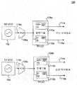
도 1은 주파수 분할 듀플렉싱(FDD) 송수신기부(transceiver section)(100)의 예를 도시한 도면이다. 예시적인 FDD 송수신기부(100)는 예시 목적으로 제공되는 것이지 제한할 목적으로 제공되지 않는다. 여기의 사상을 근거로 당업자에 의해 이해되는 바와 같이, 송수신기부(100)는 상이한 아키텍처 혹은 도 1에 도시된 것보다 상세한 구현 사항들을 가질 수 있다.1 is a diagram illustrating an example of a frequency division duplexing (FDD)
도 1에 도시된 바와 같이, 예시적인 FDD 송수신기부(100)는 수신부(receive portion)(RX) 및 송신부(transmit portion)(TX)를 포함한다. RX부는 RX 합성기(synthesizer)(102), 버퍼(buffer)(106a), 및 RX 국부 발진기(local oscillator)(LO) 신호 생성부(108a)를 포함한다. TX부는 TX 합성기(104), 버퍼(106b), 및 TX LO 신호 생성부(108b)를 포함한다.As shown in FIG. 1, the exemplary
RX 합성기(102) 및 TX 합성기(104)는 각각 전압 제어 발진기(VCO, voltage controlled oscillator)를 포함할 수 있다. RX 합성기(102) 및 TX 합성기(104)는 또한 각각, 예를 들어, VCO를 제어하여 VCO 출력 신호(118)를 생성하는 위상 동기 루프(PLL, phase locked loop) (도 1에 도시되지 않음)를 포함할 수 있다. VCO 출력 신호(118)는 RT/TX LO 신호 생성부(108)로 제공되기 전에 버퍼(106)로 공급된다.
각각의 RX 및 TX LO 신호 생성부(108a 및 108b)들은 필요에 따라 하나 이상의 분배기(divider)들을 포함할 수 있다. 예를 들어, 도 1에 도시된 바와 같이, RX LO 신호 생성부(108a)는 분배기(110a 및 112a)들을 포함한다. 분배기(110a 및 112a)들은 RX LO 신호(114a 및 116a)들을 각각 생성하기 위해 구성될 수 있으며, 이는 FDD 송수신기의 RX 믹서들에 제공된다. 유사하게, TX LO 신호 생성부(108b)는 분배기(110b 및 112b)들을 포함한다. 분배기(110b 및 112b)들은 TX LO 신호(114b 및 116b)들을 각각 생성하기 위해 구성될 수 있으며, 상기 TX LO 신호(114b 및 116b)들은 FDD 송수신기의 TX 믹서들에 제공된다. RX/TX LO 신호(114 및 116)들은, 예를 들어, 싱글엔드(single-ended) 또는 차동 위상(differential in-phase) 및 직교 위상(quadrature phase)(IQ) 신호들일 수 있다.Each of the RX and TX
전형적으로, RX/TX LO 신호(114 또는 116)를 생성하기 위해, RT/TX LO 신호 생성부들(108)에서 분배기(110 및 112)들 중 단지 하나만이 임의의 주어진 시간에서 작동한다. 따라서, 파워 업/다운 기능이 RT/TX LO 신호 생성부들(108)에서 필요에 따라 분배기(110 및 112)들을 파워 업/다운하기 위해 구현될 수 있다.Typically, only one of the distributors 110 and 112 in the RT / TX LO signal generators 108 operates at any given time to generate the RX / TX LO signal 114 or 116. Thus, the power up / down function can be implemented to power up / down the distributors 110 and 112 as needed in the RT / TX LO signal generators 108.
당업자에 의해 이해될 수 있는 바와 같이, RX 및 TX LO 신호 생성부(108a 및 108b)들은, 예를 들어 분배기의 개수 및/또는 분배기 비율을 다르게 하는 것을 포함하여, 도 1에 도시된 것과 다른 LO 신호 생성 방식들을 구현할 수 있다.As can be appreciated by those skilled in the art, the RX and TX
FDD 모드에서, 송신 및 수신 기능들은 송수신기에 의해 상이한 캐리어 주파수들에 동시에 수행된다. 따라서, 고정밀 TX 및 RX LO 신호들을 동시에 생성하여 TX 및 RX 믹서들로 전달하기 위하여 적어도 2개의 합성기들과 2개의 LO 신호 생성부들 (예시적인 FDD 송수신기부(100))이 요구된다.In FDD mode, the transmit and receive functions are performed simultaneously on different carrier frequencies by the transceiver. Thus, at least two synthesizers and two LO signal generators (exemplary FDD transceiver 100) are required to simultaneously generate and transmit high-precision TX and RX LO signals to the TX and RX mixers.
그와 같이, FDD 송수신기부(100)에서, RX 및 TX부 모두는 FDD 모드에서 동시에 ON 상태로 유지될 필요가 있다. 이는 동시에 RX 및 TX LO 신호 생성부(108a 및 108b)들과 RX 및 TX 합성기(102 및 104)들 모두를 파워 ON 상태로 유지하는 것을 포함한다.As such, in the
보통, 차세대 통신 장치용으로, 송수신기가 FDD 통신기술들뿐만 아니라 시분할 듀플렉싱(TDD) 통신기술을 지원하는 것이 바람직하다. TDD 모드에서, 송신 및 수신 기능은 개별적인 비중첩 타임 슬롯들에서 송수신기에 의해 동일하거나 상이한 주파수들에 수행된다.Usually, for next generation communication devices, it is desirable that the transceivers support FDD communication techniques as well as time division duplexing (TDD) communication techniques. In TDD mode, the transmit and receive functions are performed on the same or different frequencies by the transceiver in the respective non-overlapping timeslots.
TDD 모드에서는 언제나 최대 1개의 합성기와 1개의 LO 신호 생성부가 필요하기 때문에, 예시적인 송수신기부(100)와 같은 섹션을 갖는 FDD 송수신기부가 TDD를 지원하도록 구성될 수 있다. 제1 구성에서, FDD 송수신기부(100)의 RX 및 TX부 모두는 항상 ON 상태로 유지된다. 수신 타임 슬롯들에서, RX LO 신호(114a/116a)가 사용되고, TX LO 신호(114b/116b)가 폐기된다. 송신 타임 슬롯들에서, TX LO 신호(114b/116b)가 사용되고, RX LO 신호(114a/116a)가 폐기된다. 따라서, 이와 같은 제1 구성은 전력 소비와 듀티 사이클(duty cycle)의 관점에서 비경제적이다. 또한, 어드밴스드 4G-TDD 표준(advanced 4G-TDD standard)들이 2개의 RX/TX 모드 사이에서 극도로 빠른 천이(transition)를 요구한다는 사실에 기인하여, 이러한 RX/TX 모드 사이에서의 천이들은 차선(sub-optimal)일 수 있다.Since at most one synthesizer and one LO signal generator are required in the TDD mode at all times, an FDD transceiver having the same section as the
제2 구성에서, 전력을 절약하기 위해, FDD 송수신기부(100)의 RX 및 TX 부들이 필요에 따라 선택적으로 파워 업/다운된다. RX부는 수신 타임 슬롯 시에 파워 업되고 송신 타임 슬롯 시에 파워 다운되며, TX부는 송신 타임 슬롯 시에 파워 업되고 수신 타임 슬롯 시에 파워 다운된다. 제2 구성에 의해 일부 전력 절감이 달성될 수 있다. 그러나, 송신 및 수신 슬롯들이 일반적으로 TDD 모드에서 크게 인터리브되기(interleave) 때문에, 상기 구성은 FDD 송수신기부(100)의 RX부 및 TX부의 매우 빈번한 파워 업/다운을 필요로 하고, 결과적으로 후술하는 바와 같이 여러 가지 현저한 결함들을 야기하고 전력 절감의 감소를 초래한다.In the second configuration, to conserve power, the RX and TX portions of the
예를 들어, 특정 TDD-기반 통신 표준들에서, 슬롯들 사이에 허용된 송신/수신 천이 시간은 FDD 송수신기부(100)의 RX/TX부가 DC-상태 세틀링(settling) 및/또는 필요한 출력 주파수 허용범위에 도달하기에 너무 짧을 수 있다(예를 들어, 12.5 마이크로초). 전형적으로, RX/TX 합성기의 출력에서 노이즈를 줄이기 위해, 저주파수 노이즈를 필터링하기 위해 커패시터들을 사용한다. 완전한 충전/방전이 느린 이러한 커패시터들은 RX/TX 합성기가 TDD 슬롯 타임들에 비해 늦은 DC-상태 세틀링을 가지도록 한다. 늦은 DC-상태 세틀링을 가지므로, RX/TX 합성기의 부분들은 타임 스롯 내에 결코 완전히 파워 다운할 수 없다. 예를 들어, 합성기의 PLL은 다음 타임 슬롯의 처음에 다시 파워 업하는 시간일 때 단지 부분적으로 OFF 상태일 수 있다. 따라서, 이러한 제2 구성의 잠재적인 전력 절감은 실제로 완전히 달성되지 않는다. 또한, 늦은 DC-상태 세틀링은 합성기가 과도 조건(transient condition)하에서 동작(즉, 동작 출력을 생성)할 수 있다는 것을 또한 의미한다. 이는 공급 전압 세틀링 문제에 매우 민감한 저전압 VCO들을 갖는 합성기의 경우에 특히 바람직하지 않다.For example, in certain TDD-based communication standards, the allowed transmission / reception transit times between the slots are determined by the RX / TX portion of the
이 제2 구성에서 RX부 및 TX부의 빈번한 파워 업/다운은 바람직하지 못한 과도 현상을 또한 야기할 수 있다. 예를 들어, DC-상태 세틀링이 도달될 때까지, RX/TX 합성기의 PLL 및 VCO는 파워 업 시에 원치 않는 디바이스 특성 변경을 일반적으로 경험한다. 이러한 디바이스 특성 변경은 VCO 이득 곡선의 변동(fluctuation) (예를 들어, 콜드-투-핫(cold-to-hot) 천이에 기인함)과 PLL에 사용된 전하 펌프 회로들의 전류 불일치들을 포함할 수 있으며, 이들 모두는 VCO 출력 신호에서 원치 않는 스플(spur)을 야기할 수 있다. 또한, 이 제2 구성에는 회로의 빈번한 교정(calibration)이 또한 요구된다. 예를 들어, RX/TX 합성기의 VCO는 각각의 파워 업 후에 (가장 바람직한 동작 영역에서 동작하도록) 교정될 필요가 있다.In this second configuration, frequent power up / down of the RX and TX portions may also cause undesirable transients. For example, until DC-state settling is reached, the PLL and VCO of the RX / TX synthesizer typically experience unwanted device property changes at power-up. Such device property changes may include fluctuations in the VCO gain curve (e.g., due to a cold-to-hot transition) and current mismatches in the charge pump circuits used in the PLL , All of which can cause unwanted spurs in the VCO output signal. This second configuration also requires frequent calibration of the circuit. For example, the VCO of the RX / TX synthesizer needs to be calibrated after each power-up (to operate in the most desirable operating range).
RX 및 TX 합성기들의 빈번한 파워 업/다운은 송수신기를 파워 업하는 스위칭 레귤레이터(switching regulator)-기반 전원공급장치 (매우 높은 전력 효율성을 원함)를 또한 사용하지 못하게 한다. 대개, 스위칭 레귤레이터들은 그들의 전력 효율성을 감소시키는 부하 변경 후 늦은 세틀링(slow settling following load changes)을 가진다. RX 및 TX 합성기들의 빈번한 파워 업/다운에 의해, 스위칭 레귤레이터는 그의 전력 효율성을 낮추는 다양한 부하 조건 하에서 많은 비율의 시간을 강제로 동작한다.Frequent power up / down of the RX and TX synthesizers also prevents the use of a switching regulator-based power supply (which desires very high power efficiency) to power up the transceiver. Typically, switching regulators have slow settling following load changes after a load change that reduces their power efficiency. Due to the frequent power-up / down of the RX and TX synthesizers, the switching regulator forces a large percentage of time under various load conditions to lower its power efficiency.
본 발명의 실시예들은, 후술하는 바와 같이, FDD 송수신기들의 전력 효율이 좋은 TDD 모드 구성들을 제공한다. 실시예들은 RX 및 TX 합성기들의 타임 슬롯 동작을 방지하여, 과도 조건 하에서의 원치 않는 동작, 빈번한 교정, 및 전력 공급 효율의 감소와 같은 상술한 결점들을 피할 수 있다. 실시예들에서, 단일 합성기는 TDD 동작을 할 수 있도록 사용되므로, 전력 소비와 교정 요구를 약 50% 정도 감소시킨다. 단일 합성기는 항상 ON 상태로 유지될 수 있어, 실질적으로 일정한 부하 조건으로 전력 공급장치의 스위칭 레귤레이터를 동작할 수 있다.Embodiments of the present invention provide power efficient TDD mode configurations of FDD transceivers, as described below. Embodiments can avoid time slot operation of the RX and TX synthesizers, avoiding the above mentioned drawbacks such as undesired operation under transient conditions, frequent calibration, and reduced power supply efficiency. In embodiments, a single synthesizer is used to perform TDD operation, thereby reducing power consumption and calibration requirements by about 50%. A single synthesizer can always be kept in the ON state, so that the switching regulator of the power supply can be operated with a substantially constant load condition.
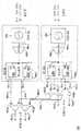
도 2는 듀얼 FDD-TDD 동작용으로 변형된 FDD 송수신기부(200)의 예를 도시한 것이다. 예시적인 FDD 송수신기부(200)는 설명 목적으로 제공되었지 제한할 목적으로 제공된 것은 아니다.2 shows an example of an
상술한 예시적인 송수신기부(100)와 같이, 예시적인 송수신기부(200)는 RX부와 TX부를 또한 포함한다. RX부는 RX 합성기(102), 버퍼(106a), 및 RX LO 신호 생성부(108a)를 포함한다. TX부는 TX 합성기(104), 버퍼(106b), 및 TX LO 신호 생성부(108b)를 포함한다.As with the
또한, 송수신기부(200)는 디멀티플렉서(de-multiplexer, 202a 및 202b)들과 멀티플렉서(204a 및 204b)들을 포함한다. 디멀티플렉서(202a 및 202b)들은 RX LO 신호 생성부(108a)의 출력부에 배치되어, RX LO 신호(114a 및 116a)들을 각각 수신한다. 송수신기 모드 (즉, FDD 모드 대 TDD 모드) 및/또는 현재 송수신기 기능 (즉, 송신 또는 수신)에 따라, 디멀티플렉서(202a 및 202b)들은 RX LO 신호(114a 및 116a)들을 RX 믹서들 (각각 신호(206a 및 206b)들을 경유하여) 또는 멀티플렉서(204a 및 204b)들 (각각 신호(208a 및 208b)들을 경유하여) 중 하나에 각각 선택적으로 연결한다.The
멀티플렉서(204a 및 204b)들은 TX LO 신호 생성부(108b)의 출력부에 배치되어, TX LO 신호(114b 및 116b)들을 각각 수신한다. 또한, 멀티플렉서(204a 및 204b)들은 디멀티플렉서(202a 및 202b)들에서부터 신호(208a 및 208b)들을 각각 수신한다. 송수신기 모드 (즉, FDD 모드 대 TDD 모드)에 따라, 멀티플렉서(204a 및 204b)들은 신호(114b/116b)들 또는 신호(208a/208b)들 중 하나를 TX 믹서들(신호(210a 및 210b)들을 각각 경유하여)에 각각 선택적으로 연결한다.
상술한 바와 같이, 일반적으로, RX/TX LO 신호 생성부(108)의 하나의 분배기만이 LO 신호(114) 또는 LO 신호(116) 중 어느 하나를 생성하기 위해 임의의 주어진 시간에서 작동한다. 따라서, 디멀티플렉서(202a 및 202b)들 (그리고 그들의 관련 출력 신호(206a/206b 및 208a/208b)들) 중 하나만 그리고 멀티플렉서(204a 및 204b)들 (그리고 그들의 관련 출력 신호(210a 및 210b)들) 중 어느 하나만이 임의의 주어진 시간에서 작동할 필요가 있을 수 있다. 이는 후술하는 FDD 송수신기부(200)의 동작 설명에서 추정된다.As described above, generally only one of the distributors of the RX / TX LO signal generator 108 operates at any given time to generate either the LO signal 114 or the LO signal 116. Thus, only one of
FDD 모드에서, 송수신기에 의한 송신 및 수신을 동시에 가능하게 하도록, FDD 송수신기부(200)의 RX부 및 TX부 모두를 ON 상태가 되도록 한다. 이 모드에서, RX LO 신호(114a 및 116a)들이 신호(206a 및 206b)들을 통해 RX 믹서들에 각각 연결되도록, 디멀티플렉서(202a 및 202b)들이 각각 구성된다. 이렇게 하여 신호(208a 및 208b)들은 작동하지 않은 상태(inactive)로 남는다. TX LO 신호(114b 및 116b)들이 신호(210a 및 210b)들을 경유하여 TX 믹서들에 각각 연결되도록, 멀티플렉서(204a 및 204b)들이 각각 구성된다.In the FDD mode, both the RX part and the TX part of the
TDD 모드에서, FDD 송수신기부(200)의 RX부는 턴 온되고 FDD 송수신기부(200)의 TX부는 턴 오프된다. 수신 타임 슬롯 동안, RX LO 신호(114a 및 116a)들이 신호(206a 및 206b)들을 경유하여 RX 믹서들에 각각 연결되도록, 디멀티플렉서(202a 및 202b)들을 각각 구성한다.In the TDD mode, the RX portion of the
송신 타임 슬롯에서, FDD 송수신기부(200)의 RX부는 TX LO 신호(212a 및 212b)들을 만들도록 구성된다. 송신 기능 및 수신 기능이 TDD 모드에서 동일하거나 상이한 캐리어 주파수들에 수행되는지 여부에 따라서, TX LO 신호(212a 및 212b)들은 RX LO 신호(114a 및 116b)와 동일하거나 상이할 수 있다. TX LO 신호(212a 및 212b)들이 신호(208a 및 208b)들을 경유하여 멀티플렉서(204a 및 204b)들에 각각 연결되도록 디멀티플렉서(202a 및 202b)들을 각각 구성한다. 멀티플렉서(204a 및 204b)들은 신호(210a 및 210b)들을 경유하여 TX 믹서들에 신호(208a 및 208b)를 교대로 각각 연결한다.In the transmit time slot, the RX portion of the
TDD 모드에서 작동하는 FDD 송수신기부(200)의 RX부만으로써, 상당한 전력 절감을 이룰 수 있다. 실시예에서, RX부는 ON 상태가 유지되거나 TDD 모드에서 단지 가끔 턴 오프된다. 따라서, 합성기들의 빈번한 파워 업/다운과 관련된 상술한 문제점들이 방지된다. 또한, 실시예에서, 전문이 참조로 여기에 합체된 "Apparatus and Method for Fast Phase Locked Loop (PLL) Settling for Cellular Time-Division Duplex (TDD) Communications Systems"을 발명의 명칭으로 하여 2012년 1월 23일에 출원된 미국특허출원번호 제13/356,137에 개시된 실시예들의 구현에 의해 RX부의 합성기(102)의 PLL은 빠른 세틀링 성능을 갖는 것을 특징으로 한다. 이는 상술한 바와 같이 RX부의 턴 온/오프의 부정적인 영향들을 줄인다.By only the RX portion of the
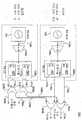
도 3은 듀얼 FDD-TDD 동작용으로 변형된 FDD 송수신기부(300)의 다른 예를 도시한 것이다. 예시적인 FDD 송수신기부(300)는 설명 목적으로 제공되었지 제한할 목적으로 제공되지 않는다.FIG. 3 shows another example of the
예시적인 송수신기부(300)는 도 2에서 상술한 예시적인 송수신기부(200)와 반대 구성을 구현한다. 구체적으로, 송수신기부(200)의 디멀티플렉서(202a 및 202b)들은 송수신기부(300)에서 RX LO 신호 생성부(108a)의 출력들에서의 멀티플렉서(304a 및 304b)들로 각각 교체된다. 송수신기부(200)의 멀티플렉서(204a 및 204b)는 송수신기부(300)에서 TX LO 신호 생성부(108b)의 출력들에서의 디멀티플렉서(302a 및 302b)들로 각각 교체된다.The
FDD 모드에서, 송수신기부(300)는 송수신기부(200)에 대하여, 디멀티플렉서(202a 및 202b)들과 같이 동작하도록 구성된 디멀티플렉서(302a 및 302b)와 멀티플렉서(204a 및 204b)와 같이 동작하도록 구성된 멀티플렉서(304a 및 304b)들로써, 상술한 바와 같이 동작한다.In FDD mode, the
TDD 모드에서, FDD 송수신기부(300)의 TX부는 턴 온되고 FDD 송수신기부(300)의 RX부는 턴 오프된다. 송신 타임 슬롯 동안, 신호(306a 및 306b)들을 경유하여 TX LO 신호(114b 및 116b)들이 TX 믹서들에 각각 연결되도록 디멀티플렉서(302a 및 302b)들을 각각 구성한다.In the TDD mode, the TX portion of the
수신 타임 슬롯 동안, FDD 송수신기부(300)의 TX부는 RX LO 신호(312a 및 312b)들을 만들도록 구성된다. 송신 및 수신 기능이 TDD 모드에서 동일하거나 상이한 캐리어 주파수들에 수행되는지 여부에 따라서, RX LO 신호(312a 및 312b)들은 TX LO 신호(114b, 116b)들과 일치하거나 상이할 수 있다. RX LO 신호(312a 및 312b)들이 신호(308a 및 308b)들을 경유하여 멀티플렉서(304a 및 304b)에 각각 연결되도록 디멀티플렉서(302a 및 302b)들을 각각 구성한다. 멀티플렉서(304a 및 304b)들은 신호(310a 및 310b)들을 경유하여 신호(308a 및 308b)들을 RX 믹서들에 각각 교대로 연결한다.During the receive time slot, the TX portion of the
TDD 모드에서 작동하는 FDD 송수신기부(300)의 TX 부만으로, 상당한 전력 절감을 달성할 수 있다. 실시예에서, TX부는 ON 상태가 유지되거나 TDD 모드에서 단지 가끔 턴 오프된다. 따라서, 합성기들의 빈번한 파워 업/다운과 관련된 상술한 문제점들이 방지된다. 또한, 실시예에서, 전문이 참조로 여기에 합체된 "Apparatus and Method for Fast Phase Locked Loop (PLL) Settling for Cellular Time-Division Duplex (TDD) Communications Systems"을 발명의 명칭으로 하여 2012년 1월 23일에 출원된 미국특허출원번호 제13/356,137에 개시된 실시예들의 구현에 의해 TX부의 합성기(104)의 PLL은 빠른 세틀링 성능을 갖는 것을 특징으로 한다. 이는 상술한 바와 같이 TX부의 턴 온/오프의 부정적인 영향들을 줄인다.Significant power savings can be achieved with only the TX portion of the
실제로, 구현 세부사항들과 동작 요건에 따라, 예시적인 송수신기부(200)가 예시적인 송수신기부(300)보다 바람직할 수 있거나, 또는 그 반대로 예시적인 송수신기부(300)가 예시적인 송수신기부(200)보다 바람직할 수 있다. 2개의 예시적인 송수신기부 중 하나를 선택함에 있어서, 예를 들어, TX부 및 RX부 각각의 전력 효율성과 소정의 TDD 송신/수신 캐리어 주파수 등을 고려한다. 예를 들어, RX 합성기는 TX 합성기보다 더 높은 주파수 범위를 지원하도록 설계될 수 있다. 따라서, 소정의 TDD 캐리어 주파수들에 따라, 송수신기부(200) 또는 송수신기부(300) 중 어느 하나가 보다 적당할 수 있다.In practice, depending on implementation details and operational requirements,
도 4는 듀얼 FDD-TDD 동작용으로 변형된 FDD 송수신기부(400)의 다른 예를 도시한 것이다. 예시적인 FDD 송수신기부(400)는 설명 목적으로 제공되었지 제한할 목적으로 제공된 것은 아니다.4 shows another example of an
예시적인 송수신기부(400)는 예시적인 송수신기부(200 및 300)들의 기능성을 조합하여 구현한다. 도 2에 도시된 바와 같이, 디멀티플렉서(202a 및 202b)들은 RX LO 신호 생성부(108a)의 출력부에 배치되지만, 설명의 편의를 위해 도 4에서는 도시되지 않았다. 도 3에 도시된 바와 같이, 디멀티플렉서(302a 및 302b)들은 TX LO 신호 생성부(108b)의 출력들에 배치된다.The
FDD 모드에서, 멀티플렉서(304a 및 304b)들에 따른 디멀티플렉서(202a 및 202b)들은 RX LO 신호(114a 및 116a)들을 신호(310a 및 310b)들을 경유하여 RX 믹서들에 각각 연결한다. 유사하게, 멀티플렉서(204a 및 204b)들에 따른 디멀티플렉서(302a 및 302b)들은 TX LO 신호(114b 및 116b)들을 신호(210a 및 210b)들을 경유하여 TX 믹서들에 각각 연결한다.In FDD mode, demultiplexers 202a and 202b according to
TDD 모드에서, FDD 송수신기부(400)의 RX부와 TX부 중 어느 하나는 턴 온되고, 나머지 하나는 턴 오프된다. 두 구성 사이에서의 선택은 상황에 따라 행해질 수 있다. RX부가 ON 상태일 때, 멀티플렉서(204a 및 204b)들은 작동하고 송수신기부(400)는 TDD 모드에서 예시적인 송수신기부(200)와 같이 동작한다. TX부가 ON 상태일 때, 멀티플렉서(304a 및 304b)들은 작동하고 송수신기부(400)는 TDD 모드에서 예시적인 송수신기부(300)와 같이 동작한다.In the TDD mode, either the RX part or TX part of the
도 5는 듀얼 FDD-TDD 동작용으로 변형된 FDD 송수신기부(500)의 다른 예를 도시한 것이다. 예시적인 FDD 송수신기부(500)는 설명 목적으로 제공되었지 제한할 목적으로 제공되지는 않는다. 예시적인 FDD 송수신기부(500)는 도 3에서 상술한 예시적인 송수신기부(300)의 변형이다. 구체적으로, 송수신기부(500)는 TDD 모드 시에 RX LO 신호들을 생성하기 위해 별개(보조) LO 신호 생성부(502)를 사용한다. 도 5에 도시된 바와 같이, LO 신호 생성부(502)는 필요에 따라 하나 이상의 보조 분배기들(auxiliary dividers)을 포함할 수 있다.5 illustrates another example of an
FDD 모드에서, FDD 송수신기부(500)의 RX부 및 TX부 모두는 파워 ON 상태로 되어, 송수신기에 의해 송신 및 수신을 동시에 할 수 있다. 이 모드에서, RX LO 신호(114a 및 116a)들이 신호(310a 및 310b)들을 경유하여 RX 믹서들에 각각 연결되도록 멀티플렉서(304a 및 304b)들을 각각 구성한다. TX LO 신호(114b 및 116b)들이 TX 믹서들에 직접적으로 연결된다 (즉, 디멀티플렉서(302a 및 302b)들이 예시적인 송수신기부(500)에서 제거된다). LO 신호 생성부(502)는 FDD 모드 시 작동하지 않는다(inactive).In the FDD mode, both the RX part and the TX part of the
TDD 모드에서, FDD 송수신기부(500)의 TX부는 턴 온되고 FDD 송수신기부(500)의 RX부는 턴 오프된다. 수신 타임 슬롯 시에, LO 신호 생성부(502)는 출력 신호(504)를 TX부의 버퍼(106b)로부터 수신하도록 구성된다. LO 신호 생성부(502)는 멀티플렉서(304a 및 304b)들에 제공되는 RX LO 신호(506a 및 506b)들을 생성한다. 멀티플렉서(304a 및 304b)들은 RX LO 신호(506a 및 506b)들을 RX 믹서들에 각각 연결한다. 송신 타임 슬롯 시에, TX LO 신호(114b 및 116b)들은 FDD 모드에서와 동일한 방식으로 TX 믹서들에 제공된다. 실시예에서, 스위칭 구조 (예를 들어, 스위치, 디멀티플렉서 등) (도 5에 도시되지 않음)는 수신 타임 슬롯 시에 출력 신호(504)를 LO 신호 생성부(502)에 그리고 송신 타임 슬롯 시에 TX LO 신호 생성부(108b)에 선택적으로 연결하기 위해 사용된다.In the TDD mode, the TX portion of the
실시예에서, LO 신호 생성부(502)는 RX 믹서기와 물리적으로 가깝게 배치된다. 이는 예시적인 송수신기부(300)에서 보다 나은 RX LO 신호(310a 및 310b)들의 신호 품질을 야기한다. 그 이유는, 예를 들어, LO 신호 생성부(502)의 IQ LO 신호(506a 및 506b)들이 송수신기부(300)에서의 IQ LO 신호(312a 및 312b)들보다 멀티플렉서(304a 및 304b)들에 도달하는데 훨씬 짧은 거리를 횡단하기 때문이다. 버퍼(106b)의 출력 신호(504)의 신호 품질은, 출력 신호(504)가 IQ 형태가 아니기 때문에 (즉, I와 Q 구성요소들 사이에 위상 오류들이 진행할 위험이 없음), LO 신호 생성부(502)까지 상대적으로 긴 거리를 횡단하게 됨으로써 현저히 영향을 받지 않는다는 점을 주목하여야 한다.In an embodiment, the
여기의 사상을 근거로 당업자에 의해 이해될 수 있는 바와 같이, 다른 변형에서, TDD 모드에서 FDD 송수신기부의 RX부가 턴 온되고 FDD 송수신기부의 TX부가 턴 오프되도록, FDD 송수신기부(500)가 구현될 수 있다. 이에 의해, LO 신호 생성부(502)는 버퍼(106a)의 출력으로부터 각 신호를 수신 및 분할하여 TDD 모드 시에 TX LO 신호들을 생성한다.In another variation, as can be understood by those skilled in the art based on the ideas here, the
실시예들이 특정 기능들과 그들 관계의 구현을 설명하는 기능적인 구성 요소들의 도움으로 상술되었다. 이러한 기능적 구성요소들의 경계들은 본 명세서의 편의를 위해 여기에서 임의로 정의되어 왔다. 특정 기능들 및 그 관계들이 적절히 수행되는 한 변경 가능한 경계들이 정의될 수 있다.The embodiments have been described above with the aid of functional components that illustrate particular functions and implementations of those relationships. The boundaries of these functional components have been arbitrarily defined herein for convenience of the present specification. Alterable boundaries can be defined as long as certain functions and their relationships are properly performed.
상기 특정 실시예들의 앞선 설명들은 본 발명의 일반적인 본질을 완전히 드러내서 다른 사람들이 본 발명의 기술 분야 내에서 지식을 적용함으로써 과도한 실험 없이, 상기 본 발명의 일반적인 개념으로부터 벗어나지 않는 특정 실시예들과 같은 다양한 응용들을 위해 용이하게 변경 및/또는 적용할 수 있을 것이다. 그러므로, 그러한 적용들 및 변경들은 여기에 나타난 교시 및 안내에 기초하여 공개된 실시예들의 등가들의 의미 및 범위 내에 있도록 의도된 것이다. 여기에서의 용어 또는 전문어는 설명의 목적을 위한 것으로 제한의 목적이 아니며, 상기 본 설명의 용어 또는 전문어는 상기 교시들 및 안내를 고려하여 당업자에 의해 해설될 수 있도록 이해되는 것이다.The foregoing description of specific embodiments is provided to enable any person of ordinary skill in the art to practice the present invention without undue experimentation by applying knowledge within the skill of the art to the full disclosure of the general nature of the invention, And may be readily modified and / or adapted for various applications. It is therefore intended that such applications and modifications be within the meaning and range of equivalents of the disclosed embodiments based on the teachings and guidance presented herein. It is to be understood that the terminology or the phraseology herein is for the purpose of description and not for the purpose of limitation, and that the terminology or the phraseology of the present specification is to be interpreted by those skilled in the art in light of the above teachings and guidance.
본 발명의 실시예들의 넓이 및 범위는 상기 설명된 예시적인 실시예들 중 어느 것에 의해 제한되는 것이 아니라, 이하 청구항들 및 그들의 등가물들에 따라서만 정의되어야 한다.The breadth and scope of embodiments of the present invention should not be limited by any of the above-described exemplary embodiments, but should be defined only in accordance with the following claims and their equivalents.
Claims (15)
Translated fromKorean송신 합성기(transmit synthesizer); 및
송신 국부 발진기(LO, local oscilator) 신호 생성부를 포함하는, 상기 송신부;
수신부(receive portion)로서,
제1 클록 신호를 생성하도록 구성된 수신 합성기; 및
상기 제1 클록 신호로부터 제1 LO 신호를 생성하도록 구성된 수신 LO 신호 생성부를 포함하는, 상기 수신부; 및
송수신기의 시분할 듀플렉싱(TDD, time division duplexing) 모드에서 상기 제1 LO 신호를 상기 TDD 모드의 수신 타임 슬롯 시에 수신 믹서에 결합하고 상기 TDD 모드의 송신 타임 슬롯 시에 송신 믹서에 결합하도록 구성된 스위칭 구조(switching structure)를 포함하고,
상기 수신 타임 슬롯 시에 상기 제1 LO 신호는 RX LO 신호이고, 상기 송신 타임 슬롯 시에 상기 제1 LO 신호는 TX LO 신호이고,
상기 TDD 모드에서 송신 기능과 수신 기능이 동일한 캐리어 주파수에서 수행되면 상기 RX LO 신호와 상기 TX LO 신호는 동일하고, 상기 TDD 모드에서 송신 기능과 수신 기능이 상이한 캐리어 주파수에서 수행되면 상기 RX LO 신호와 상기 TX LO 신호는 상이한, 송수신기.As a transmit portion,
A transmit synthesizer; And
A transmission local oscillator (LO) signal generator;
As a receive portion,
A receive synthesizer configured to generate a first clock signal; And
A receiving LO signal generator configured to generate a first LO signal from the first clock signal; And
A first LO signal coupled to a receive mixer at a receive time slot of the TDD mode in a time division duplexing (TDD) mode of the transceiver and configured to couple to a transmit mixer at a transmit time slot of the TDD mode; Including a switching structure,
Wherein the first LO signal is an RX LO signal at the reception time slot and the first LO signal is a TX LO signal at the transmission time slot,
If the transmission function and the reception function are performed at the same carrier frequency in the TDD mode, the RX LO signal and the TX LO signal are identical. If the transmission function and the reception function are performed at the different carrier frequency in the TDD mode, Wherein the TX LO signal is different.
제1 클록 신호를 생성하도록 구성된 송신 합성기; 및
상기 제1 클록 신호로부터 제1 LO 신호를 생성하도록 구성된 송신 국부 발진기(LO, local oscilator) 신호 생성부를 포함하는, 상기 송신부;
수신부로서,
수신 합성기; 및
수신 LO 신호 생성부를 포함하는, 상기 수신부; 및
송수신기의 시분할 듀플렉싱(TDD, time division duplexing) 모드에서 상기 제1 LO 신호를 상기 TDD 모드의 수신 타임 슬롯 시에 수신 믹서에 결합하도록 구성되고, 상기 TDD 모드의 송신 타임 슬롯 시에 송신 믹서에 결합하도록 구성되는 스위칭 구조를 포함하고,
상기 수신 타임 슬롯 시에 상기 제1 LO 신호는 RX LO 신호이고, 상기 송신 타임 슬롯 시에 상기 제1 LO 신호는 TX LO 신호이고,
상기 TDD 모드에서 송신 기능과 수신 기능이 동일한 캐리어 주파수에서 수행되면 상기 RX LO 신호와 상기 TX LO 신호는 동일하고, 상기 TDD 모드에서 송신 기능과 수신 기능이 상이한 캐리어 주파수에서 수행되면 상기 RX LO 신호와 상기 TX LO 신호는 상이한, 송수신기.As a transmitting unit,
A transmit synthesizer configured to generate a first clock signal; And
A local oscillator (LO) signal generator configured to generate a first LO signal from the first clock signal;
As a receiving unit,
Receiving synthesizer; And
A receiving LO signal generating unit; And
And to combine the first LO signal into a receive mixer during a receive time slot of the TDD mode in a time division duplexing (TDD) mode of the transceiver, And a switching structure configured to < RTI ID = 0.0 >
Wherein the first LO signal is an RX LO signal at the reception time slot and the first LO signal is a TX LO signal at the transmission time slot,
If the transmission function and the reception function are performed at the same carrier frequency in the TDD mode, the RX LO signal and the TX LO signal are identical. If the transmission function and the reception function are performed at the different carrier frequency in the TDD mode, Wherein the TX LO signal is different.
클록 신호를 생성하도록 구성된 송신 합성기; 및
국부 발진기(LO) 신호 생성부를 포함하는, 상기 송신부,
보조 LO 신호 생성부, 및
송수신기의 시분할 듀플렉싱(TDD) 모드에서, 상기 클록 신호를 상기 TDD 모드의 수신 타임 슬롯 시에 상기 보조 LO 신호 생성부에 결합하고 상기 TDD 모드의 송신 타임 슬롯 시에 상기 LO 신호 생성부에 결합하도록 구성된 스위칭 구조를 포함하고,
상기 수신 타임 슬롯 시에 상기 보조 LO 신호 생성부는 상기 클록 신호로부터 RX LO 신호를 생성하고, 상기 송신 타임 슬롯 시에 상기 LO 신호 생성부는 상기 클록 신호로부터 TX LO 신호를 생성하고,
상기 TDD 모드에서 송신 기능과 수신 기능이 동일한 캐리어 주파수에서 수행되면 상기 RX LO 신호와 상기 TX LO 신호는 동일하고, 상기 TDD 모드에서 송신 기능과 수신 기능이 상이한 캐리어 주파수에서 수행되면 상기 RX LO 신호와 상기 TX LO 신호는 상이한, 송수신기.As a transmitting unit,
A transmit synthesizer configured to generate a clock signal; And
A local oscillator (LO) signal generator,
An auxiliary LO signal generator, and
In a time division duplexing (TDD) mode of a transceiver, the clock signal is coupled to the auxiliary LO signal generator at a reception time slot of the TDD mode and coupled to the LO signal generator at a transmission time slot of the TDD mode A switching structure configured,
Wherein the auxiliary LO signal generator generates an RX LO signal from the clock signal at the reception time slot and the LO signal generator generates a TX LO signal from the clock signal at the transmission time slot,
If the transmission function and the reception function are performed at the same carrier frequency in the TDD mode, the RX LO signal and the TX LO signal are identical. If the transmission function and the reception function are performed at the different carrier frequency in the TDD mode, Wherein the TX LO signal is different.
Applications Claiming Priority (4)
| Application Number | Priority Date | Filing Date | Title |
|---|---|---|---|
| US201161556094P | 2011-11-04 | 2011-11-04 | |
| US61/556,094 | 2011-11-04 | ||
| US13/432,528 | 2012-03-28 | ||
| US13/432,528US8902796B2 (en) | 2011-11-04 | 2012-03-28 | Power-efficient multi-mode transceiver synthesizer configurations |
Publications (2)
| Publication Number | Publication Date |
|---|---|
| KR20130049715A KR20130049715A (en) | 2013-05-14 |
| KR101475052B1true KR101475052B1 (en) | 2014-12-22 |
Family
ID=46799970
Family Applications (1)
| Application Number | Title | Priority Date | Filing Date |
|---|---|---|---|
| KR1020120105839AExpired - Fee RelatedKR101475052B1 (en) | 2011-11-04 | 2012-09-24 | Power-efficient multi-mode transceiver synthesizer configurations |
Country Status (5)
| Country | Link |
|---|---|
| US (1) | US8902796B2 (en) |
| EP (1) | EP2590261A2 (en) |
| KR (1) | KR101475052B1 (en) |
| CN (1) | CN103095323B (en) |
| TW (1) | TWI459731B (en) |
Families Citing this family (4)
| Publication number | Priority date | Publication date | Assignee | Title |
|---|---|---|---|---|
| US9548779B2 (en)* | 2014-04-03 | 2017-01-17 | Rafael Microelectronics, Inc. | Multi-user satellite receiving system and method thereof |
| CN105429638A (en)* | 2014-09-17 | 2016-03-23 | 常熟市荣兴化纺有限责任公司 | Integrated decimal microwave frequency synthesizer with low phase noise |
| TW201626734A (en)* | 2015-01-15 | 2016-07-16 | 力祥半導體股份有限公司 | Transceiver and operating method thereof |
| CN114124113A (en)* | 2020-08-28 | 2022-03-01 | 华为技术有限公司 | RF chips, baseband chips and WLAN equipment |
Citations (3)
| Publication number | Priority date | Publication date | Assignee | Title |
|---|---|---|---|---|
| US5423076A (en)* | 1993-09-24 | 1995-06-06 | Rockwell International Corporation | Superheterodyne tranceiver with bilateral first mixer and dual phase locked loop frequency control |
| US5465409A (en)* | 1994-03-07 | 1995-11-07 | Motorola, Inc. | Radio architecture with dual frequency source selection |
| US20110195675A1 (en)* | 2010-02-05 | 2011-08-11 | Blue Wonder Communications Gmbh | Rf transceiver and modem comprising such a transceiver |
Family Cites Families (13)
| Publication number | Priority date | Publication date | Assignee | Title |
|---|---|---|---|---|
| JPH1084299A (en)* | 1996-09-09 | 1998-03-31 | Matsushita Electric Ind Co Ltd | Time division multiplexed FDD / TDD dual mode radio and time division multiplexed TDD dual band radio |
| KR100234129B1 (en) | 1997-06-21 | 1999-12-15 | 윤종용 | Apparatus and method using time division method |
| FI112741B (en)* | 1998-11-26 | 2003-12-31 | Nokia Corp | Method and apparatus for transmitting and receiving RF signals at various radio interfaces of data transmission systems |
| DE10228757A1 (en)* | 2002-06-27 | 2004-01-22 | Infineon Technologies Ag | Receiver arrangement, especially for mobile radio |
| US6952594B2 (en)* | 2002-11-22 | 2005-10-04 | Agilent Technologies, Inc. | Dual-mode RF communication device |
| US9106316B2 (en)* | 2005-10-24 | 2015-08-11 | Parkervision, Inc. | Systems and methods of RF power transmission, modulation, and amplification |
| US8290447B2 (en) | 2007-01-19 | 2012-10-16 | Wi-Lan Inc. | Wireless transceiver with reduced transmit emissions |
| TWI439054B (en) | 2007-03-30 | 2014-05-21 | Mstar Semiconductor Inc | Frequency synthesizer and frequency synthesizing method |
| ATE520199T1 (en) | 2008-01-25 | 2011-08-15 | Nxp Bv | IMPROVEMENTS IN OR RELATED TO RADIO RECEIVER |
| GB2456648B (en) | 2008-01-28 | 2012-04-11 | Cambridge Silicon Radio Ltd | Local oscillator circuit for a signal transmitter or receiver |
| US9287886B2 (en) | 2008-02-29 | 2016-03-15 | Qualcomm Incorporated | Dynamic reference frequency for fractional-N Phase-Locked Loop |
| JP2010011376A (en)* | 2008-06-30 | 2010-01-14 | Kddi Corp | Receiver using multiple bandwidths other than existing service bandwidths, program, and method |
| US8300680B2 (en) | 2009-06-11 | 2012-10-30 | Qualcomm Incorporated | Apparatus and method for dynamic scaling of ADC sampling rate to avoid receiver interference |
- 2012
- 2012-03-28USUS13/432,528patent/US8902796B2/ennot_activeExpired - Fee Related
- 2012-08-29EPEP12006125.4Apatent/EP2590261A2/ennot_activeWithdrawn
- 2012-09-14TWTW101133693Apatent/TWI459731B/ennot_activeIP Right Cessation
- 2012-09-24KRKR1020120105839Apatent/KR101475052B1/ennot_activeExpired - Fee Related
- 2012-09-28CNCN201210372266.XApatent/CN103095323B/ennot_activeExpired - Fee Related
Patent Citations (3)
| Publication number | Priority date | Publication date | Assignee | Title |
|---|---|---|---|---|
| US5423076A (en)* | 1993-09-24 | 1995-06-06 | Rockwell International Corporation | Superheterodyne tranceiver with bilateral first mixer and dual phase locked loop frequency control |
| US5465409A (en)* | 1994-03-07 | 1995-11-07 | Motorola, Inc. | Radio architecture with dual frequency source selection |
| US20110195675A1 (en)* | 2010-02-05 | 2011-08-11 | Blue Wonder Communications Gmbh | Rf transceiver and modem comprising such a transceiver |
Also Published As
| Publication number | Publication date |
|---|---|
| US20130114469A1 (en) | 2013-05-09 |
| US8902796B2 (en) | 2014-12-02 |
| KR20130049715A (en) | 2013-05-14 |
| EP2590261A2 (en) | 2013-05-08 |
| TWI459731B (en) | 2014-11-01 |
| CN103095323B (en) | 2016-01-20 |
| TW201320632A (en) | 2013-05-16 |
| CN103095323A (en) | 2013-05-08 |
Similar Documents
| Publication | Publication Date | Title |
|---|---|---|
| KR100579680B1 (en) | Simplified Reference Frequency Distribution in Mobile Phones | |
| KR0178619B1 (en) | Apparatus and method for operating a phase locked loop frequency synthesizer responsive to radio frequency channel spacing | |
| KR101475052B1 (en) | Power-efficient multi-mode transceiver synthesizer configurations | |
| KR20050121753A (en) | Dual antenna system having one phase lock loop | |
| US7792510B2 (en) | Multi-band frequency synthesizer | |
| EP1775843A1 (en) | Local oscillator with injection pulling suppression and spurious products filtering | |
| CN115603763A (en) | Multi-channel signal synthesis circuit and multi-channel signal synthesis method | |
| CN111884666A (en) | Multi-mode multi-channel radio frequency receiver chip adopting phase-locked loop multiplexing | |
| KR101797695B1 (en) | Modular frequency divider and mixer configuration | |
| US8170001B2 (en) | Technique for synchronizing network access modules in a mobile communication device | |
| WO2005043745A2 (en) | Fast-hopping frequency synthesizer | |
| EP1557951B1 (en) | Frequency generator with multiple voltage-controlled oscillators | |
| EP1503509A1 (en) | Mobile communication apparatus | |
| KR100188162B1 (en) | Apparatus and method for enabling elements of a phase locked loop | |
| EP3149857A1 (en) | Reconfigurable frequency divider | |
| KR101351589B1 (en) | System for multi antenna communication system | |
| CN111464181B (en) | Radio frequency signal source | |
| EP1656741B1 (en) | Provision of local oscillator signals | |
| HK1180466A (en) | Power-efficient multi-mode transceiver synthesizer configurations | |
| WO2015175321A1 (en) | Vco-coupling mitigation in a multiple-carrier, carrier aggregation receiver | |
| JP5947934B2 (en) | Wireless communication device | |
| JP4625030B2 (en) | Communications system | |
| HK1107733A (en) | Provision of local oscillator signals | |
| EP1003289A1 (en) | Portable radio device | |
| KR20000065898A (en) | Radio port up/down converter multiplex PLL synthesizer supplier |
Legal Events
| Date | Code | Title | Description |
|---|---|---|---|
| A201 | Request for examination | ||
| PA0109 | Patent application | St.27 status event code:A-0-1-A10-A12-nap-PA0109 | |
| PA0201 | Request for examination | St.27 status event code:A-1-2-D10-D11-exm-PA0201 | |
| D13-X000 | Search requested | St.27 status event code:A-1-2-D10-D13-srh-X000 | |
| PG1501 | Laying open of application | St.27 status event code:A-1-1-Q10-Q12-nap-PG1501 | |
| D14-X000 | Search report completed | St.27 status event code:A-1-2-D10-D14-srh-X000 | |
| E902 | Notification of reason for refusal | ||
| PE0902 | Notice of grounds for rejection | St.27 status event code:A-1-2-D10-D21-exm-PE0902 | |
| P11-X000 | Amendment of application requested | St.27 status event code:A-2-2-P10-P11-nap-X000 | |
| P13-X000 | Application amended | St.27 status event code:A-2-2-P10-P13-nap-X000 | |
| E90F | Notification of reason for final refusal | ||
| PE0902 | Notice of grounds for rejection | St.27 status event code:A-1-2-D10-D21-exm-PE0902 | |
| P11-X000 | Amendment of application requested | St.27 status event code:A-2-2-P10-P11-nap-X000 | |
| P13-X000 | Application amended | St.27 status event code:A-2-2-P10-P13-nap-X000 | |
| E701 | Decision to grant or registration of patent right | ||
| PE0701 | Decision of registration | St.27 status event code:A-1-2-D10-D22-exm-PE0701 | |
| PR0701 | Registration of establishment | St.27 status event code:A-2-4-F10-F11-exm-PR0701 | |
| PR1002 | Payment of registration fee | St.27 status event code:A-2-2-U10-U11-oth-PR1002 Fee payment year number:1 | |
| PG1601 | Publication of registration | St.27 status event code:A-4-4-Q10-Q13-nap-PG1601 | |
| PN2301 | Change of applicant | St.27 status event code:A-5-5-R10-R11-asn-PN2301 | |
| PN2301 | Change of applicant | St.27 status event code:A-5-5-R10-R14-asn-PN2301 | |
| LAPS | Lapse due to unpaid annual fee | ||
| PC1903 | Unpaid annual fee | St.27 status event code:A-4-4-U10-U13-oth-PC1903 Not in force date:20171216 Payment event data comment text:Termination Category : DEFAULT_OF_REGISTRATION_FEE | |
| PC1903 | Unpaid annual fee | St.27 status event code:N-4-6-H10-H13-oth-PC1903 Ip right cessation event data comment text:Termination Category : DEFAULT_OF_REGISTRATION_FEE Not in force date:20171216 |