KR101474826B1 - Adjusting repeater gains based upon received downlink power level - Google Patents
Adjusting repeater gains based upon received downlink power levelDownload PDFInfo
- Publication number
- KR101474826B1 KR101474826B1KR1020147010951AKR20147010951AKR101474826B1KR 101474826 B1KR101474826 B1KR 101474826B1KR 1020147010951 AKR1020147010951 AKR 1020147010951AKR 20147010951 AKR20147010951 AKR 20147010951AKR 101474826 B1KR101474826 B1KR 101474826B1
- Authority
- KR
- South Korea
- Prior art keywords
- repeater
- signal
- power
- gain
- downlink
- Prior art date
- Legal status (The legal status is an assumption and is not a legal conclusion. Google has not performed a legal analysis and makes no representation as to the accuracy of the status listed.)
- Expired - Fee Related
Links
Images


Classifications
- H—ELECTRICITY
- H04—ELECTRIC COMMUNICATION TECHNIQUE
- H04B—TRANSMISSION
- H04B7/00—Radio transmission systems, i.e. using radiation field
- H04B7/14—Relay systems
- H04B7/15—Active relay systems
- H04B7/155—Ground-based stations
- H04B7/15564—Relay station antennae loop interference reduction
- H04B7/15578—Relay station antennae loop interference reduction by gain adjustment
Landscapes
- Engineering & Computer Science (AREA)
- Computer Networks & Wireless Communication (AREA)
- Signal Processing (AREA)
- Mobile Radio Communication Systems (AREA)
- Radio Relay Systems (AREA)
Abstract
Translated fromKoreanDescription
Translated fromKorean특허를 위한 본원은 공동-계류 중인 다음 미국 특허 출원들에 관련된다:The subject matter of the patent relates to co-pending U.S. patent applications:
본원과 동시에 출원되고 본 양수인에게 양도되며 인용에 의해 명백히 포함되는, Barriac 등에 의한 어토니 도킷 번호 제102657호의 "SETTING GAINS IN AN INTERFERENCE CANCELLATION REPEATER BASED ON PATH LOSS;" 및&Quot; SETTING GAINS IN AN INTERFERENCE CANCELLATION REPEATER BASED ON PATH LOSS; "filed concurrently herewith and assigned to the assignee and expressly incorporated by reference, And
2010년 1월 13일자로 출원되고 본 양수인에게 양도되고 인용에 의해 명백히 포함되며, 어토니 도킷 번호 제092498호를 갖는 미국 특허 출원 번호 12/686,608의 "USE OF RF REFERENCE IN A DIGITAL BASEBAND INTERFERENCE CANCELLATION REPEATER."US patent application Ser. No. 12 / 686,608, filed January 13, 2010, assigned to the assignee and expressly incorporated by reference, discloses a "USE OF RF REFERENCE IN A DIGITAL BASEBAND INTERFERENCE CANCELLATION REPEATER "
본 개시내용의 양상들은 일반적으로 무선 통신 시스템들, 보다 구체적으로는 무선 리피터들에서의 사용을 위한 업링크 및/또는 다운링크 이득 조정 방법들 및 장치들에 관한 것이다.Aspects of the present disclosure generally relate to methods and apparatus for uplink and / or downlink gain adjustment for use in wireless communication systems, and more particularly wireless repeaters.
무선 통신 시스템들에서, 이동국(MS)들은 주변의 지리 영역 내에 서비스를 제공할 수 있는 하나 또는 그 초과의 기지국 단말 시스템(BTS)들과 신호들을 교환할 수 있다. BTS들의 조정된 네트워크는 광범위한 커버리지 영역에 무선 통신 서비스를 제공할 수 있다. 그러나, 다양한 지리적, 전자기적 및/또는 경제적 제약들로 인해, BTS들의 네트워크는 원하는 커버리지 영역 내의 어떤 영역들에 충분한 통신 서비스들을 제공하지 못할 수 있다. 커버리지 영역들의 이러한 "갭(gap)들" 또는 "홀(hole)들"은 리피터들의 사용에 의해 메꿔질 수 있다.In wireless communication systems, mobile stations (MSs) may exchange signals with one or more base station terminal systems (BTSs) capable of providing services in the surrounding geographic area. The coordinated network of BTSs can provide wireless communication services in a wide coverage area. However, due to various geographical, electromagnetic and / or economic constraints, the network of BTSs may not be able to provide sufficient communication services to certain areas within the desired coverage area. These "gaps" or "holes" of coverage areas may be overcome by use of repeaters.
일반적으로, 리피터는 고 이득 양-방향성 증폭기이다. 리피터들은 업링크 방향(MS로부터 BTS로) 및 다운링크 방향(BTS로부터 MS로) 둘 다에서 신호들을 수신하고, 증폭하며 재-송신할 수 있다. 리피터는 이전에 BTS에 의해 서비스되지 않았던 커버리지 홀에 통신 서비스를 제공할 수 있다. 리피터들은 또한 커버리지 영역의 위치를 이동시키거나 커버리지 영역의 모양을 변경함으로써 섹터의 커버리지 영역을 확대할 수 있다. 종래의 리피터들은 MS가 위치를 바꾸고 그리고/또는 채널 상태들이 변화함에 따라 최적이 아닐 수 있는 고정된 이득들을 사용할 수 있다. 더욱이, 양호한 시스템 성능에 있어 전력 제어가 중요한 통신 시스템들(예를 들어, CDMA 시스템들)에서, 셀 내의 각 MS는 그 전력 설정들을 서빙 BTS의 직접 제어 하에 가질 수 있다. 고정된 리피터 이득을 갖는 종래의 리피터들은 이러한 표준 타입들의 BTS 전력 제어에 잘 따르지 않을 수 있다.Typically, the repeater is a high gain bi-directional amplifier. The repeaters can receive, amplify, and re-transmit signals in both the uplink direction (MS to BTS) and the downlink direction (BTS to MS). The repeater may provide communication services to coverage holes that were not previously serviced by the BTS. Repeaters can also extend the coverage area of a sector by moving the location of the coverage area or changing the shape of the coverage area. Conventional repeaters may use fixed gains that may not be optimal as the MS changes position and / or channel conditions change. Moreover, in communication systems where power control is important for good system performance (e.g., CDMA systems), each MS in a cell can have its power settings under the direct control of the serving BTS. Conventional repeaters with fixed repeater gains may not be well suited to BTS power control of these standard types.
또한, 리피터는 노이즈 없는 디바이스가 아니라 BTS의 수신기에 추가 노이즈를 제공할 수 있다. 하나의 리피터는 BTS의 노이즈 플로어(floor)를 현저하게 증가시키지 않을 수도 있지만, 많은 리피터들의 누적된 효과는 BTS의 노이즈 플로어를 현저하게 올리고, 따라서 커버리지 영역의 통신 링크들의 효율성을 감소시킬 수 있다. 다시 BTS로 가는 신호 및 노이즈 브로드캐스트 양은 리피터 이득 및 리피터 대 도너 안테나 이득들을 조정함으로써 조종될 수 있지만, 종래의 리피터들에서 간단하게 전체 링크 이득을 원하는 값으로 설정하는 것은 난제일 수 있다.In addition, the repeater may provide additional noise to the receiver of the BTS rather than the noise-free device. One repeater may not significantly increase the noise floor of the BTS, but the cumulative effect of many repeaters can significantly increase the noise floor of the BTS and thus reduce the efficiency of the communication links in the coverage area. Again, the amount of signal to the BTS and the amount of noise broadcast can be steered by adjusting the repeater gain and the repeater to donor antenna gains, but simply setting the overall link gain to the desired value in conventional repeaters can be daunting.
더욱이, 어떤 리피터들은 디지털 도메인에서 다양한 신호 프로세싱 동작들을 수행할 수 있다(예를 들어, 업링크 및 다운링크 채널들 사이의 피드백을 감소시키도록 설계된 간섭 소거 리피터들). 따라서, 이러한 리피터들은, 통상적으로 아날로그 신호 입력의 동적 범위가 아날로그-투-디지털 변환기(ADC)에 의해 출력되는 비트들의 수에 따라 지정된 범위 내에 있게 요구하는 아날로그-투-디지털 변환기(ADC)들을 사용할 것이다. 입력 아날로그 신호가 ADC의 동적 범위를 초과하면, 비선형 형태들의 노이즈가 초래될 수 있다. 예를 들어, 입력 아날로그 신호가 너무 낮으면, 양자화 노이즈가 우세하게 되고 디지털 변환 프로세스의 품질을 상당히 악화시킬 수 있다. 반대로, 입력 아날로그 신호 레벨이 너무 높으면, ADC가 포화될 것이고, ADC의 출력의 전체 스케일 값이 초과될 것이다.Furthermore, some repeaters may perform various signal processing operations in the digital domain (e.g., interference canceling repeaters designed to reduce feedback between uplink and downlink channels). Thus, such repeaters use analog-to-digital converters (ADCs) that typically require the dynamic range of the analog signal input to be within a specified range depending on the number of bits output by the analog-to-digital converter will be. If the input analog signal exceeds the dynamic range of the ADC, nonlinear forms of noise may result. For example, if the input analog signal is too low, the quantization noise may dominate and the quality of the digital conversion process may deteriorate significantly. Conversely, if the input analog signal level is too high, the ADC will saturate and the full scale value of the ADC's output will be exceeded.
이러한 타입들의 비선형 왜곡을 피하기 위한 종래의 접근들은 통상적으로 ADC에 맞도록 아날로그 신호의 동적 범위를 제한하는 자동 이득 제어기(AGC)들을 수반한다. 그러나, 간섭 소거 리피터들에 대해서는, 신호 진폭들에서의 스텝 변화들이 오실레이션을 야기할 수 있기 때문에 AGC는 피드백 채널을 정확히 추정하는 것을 방해한다. 따라서, 간섭 소거 리피터들에 대해서는, ADC들은 통상적으로 리피터의 프론트 엔드에 나타나는 통신 신호들 및 피드백 신호들 둘 다를 포함하는, 넓은 범위의 레벨들의 입력 신호들의 레벨들을 적절히 수용하기 위해 더 넓은 동적 영역(즉, 많은 수의 비트들)을 사용한다. 그러한 넓은 동적 범위들을 수용할 수 있는 ADC들을 사용하는 것은 ADC 컴포넌트들 자신, 및 ADC들에 의해 제공되는 더 많은 비트들을 수용해야 하는 후속 디지털 컴포넌트들 둘 다에 대한 비용들을 증가시킨다.Conventional approaches to avoiding these types of nonlinear distortion typically involve automatic gain controllers (AGCs) that limit the dynamic range of the analog signal to match the ADC. However, for interference canceled repeaters, the AGC prevents precise estimation of the feedback channel because step changes in signal amplitudes can cause oscillation. Thus, for the interference canceling repeaters, the ADCs typically use a wider dynamic range (< Desc / Clms Page number 10 > to accommodate the wide range of levels of input signals, including both the communication signals and feedback signals appearing at the front end of the repeater That is, a large number of bits). The use of ADCs capable of accommodating such wide dynamic ranges increases the costs for both the ADC components themselves and for subsequent digital components that have to accommodate the more bits provided by the ADCs.
따라서, BTS의 수신기에서 보이는 노이즈 플로어를 감소시키고 디지털 신호 프로세싱 리피터들의 ADC들 및 관련 디지털 컴포넌트들의 비용들을 감소시키기 위해 간단하고 비용 효과적인 기술들을 사용하여 리피터들 내의 이득을 조정하는 것이 바람직할 수 있다.Thus, it may be desirable to adjust the gain in the repeaters using simple and cost effective techniques to reduce the noise floor seen at the receiver of the BTS and reduce the costs of the ADCs and associated digital components of the digital signal processing repeaters.
본원 발명의 예시적인 실시예들은 수신된 다운링크 전력 레벨에 기초하여 리피터 이득들을 조정하는 시스템들 및 방법들에 관한 것이다.Exemplary embodiments of the present invention are directed to systems and methods for adjusting repeater gains based on a received downlink power level.
일 실시예에서, 리피터 내의 이득들을 제어하는 방법이 제공된다. 그 방법은 이동국(MS)의 송신 전력을 제어하는 전력 제어 설정 포인트 값을 결정하는 단계, 및 기지국 송수신기 시스템(BTS)으로부터 다운링크 신호를 수신하는 단계를 포함할 수 있다. 그 방법은 수신된 다운링크 신호의 전력을 측정하는 단계, 및 리피터의 업링크에서 예측되는 신호의 전력 레벨을 계산하는 단계를 더 포함할 수 있고, 여기에서 계산하는 단계는 측정된 다운링크 전력 및 전력 제어 설정 포인트 값에 기초한다. 마지막으로, 그 방법은 계산된 전력 레벨에 기초하여 적어도 하나의 증폭기의 이득을 조정하는 단계를 더 포함할 수 있다.In one embodiment, a method of controlling gains in a repeater is provided. The method may include determining a power control set point value that controls a transmit power of a mobile station (MS), and receiving a downlink signal from a base station transceiver system (BTS). The method may further include measuring the power of the received downlink signal and calculating a power level of the signal predicted in the uplink of the repeater, Power control set point value. Finally, the method may further comprise adjusting the gain of the at least one amplifier based on the calculated power level.
그 방법의 다른 실시예에서, 전력 제어 설정 포인트 값을 결정하는 단계는 제어 채널에 제공된 값을 판독하는 단계, 메모리에 저장된 값을 리트리빙하는 단계, 데이터 채널에 제공된 메시지를 판독하는 단계, 및/또는 심플 메시지 서비스(SMS) 메시지로부터 값을 수신하는 단계를 더 포함할 수 있다.In another embodiment of the method, the step of determining the power control setpoint value comprises the steps of reading the value provided to the control channel, retrieving the value stored in the memory, reading the message provided to the data channel, and / Or receiving a value from a Simple Messaging Service (SMS) message.
그 방법의 다른 실시예에서, 수신된 다운링크 신호의 전력을 측정하는 단계는 누설 신호를 제거하기 위해 결합된 신호에 간섭 소거를 수행하는 단계, 및 간섭 소거 후에 수신된 다운링크 신호의 전력 레벨을 계산하는 단계를 더 포함할 수 있다.In another embodiment of the method, measuring the power of the received downlink signal comprises performing interference cancellation on the combined signal to remove the leakage signal, and determining a power level of the received downlink signal after interference cancellation And a step of calculating the number of steps.
다른 실시예에서, 기지국으로부터 수신된 다운링크 전력을 측정하는 것에 기초하여 이득들을 제어하는 간섭 소거 리피터가 제공된다. 간섭 소거 리피터는 도너 안테나에 커플링된 제 1 송수신기, 서빙 안테나에 커플링된 제 2 송수신기, 및 제 1 송수신기 및 제 2 송수신기에 커플링된 베이스밴드 프로세서를 포함할 수 있다. 베이스밴드 프로세서는 이동국(MS)의 송신 전력을 제어하는 전력 제어 설정 포인트 값을 결정하고, 기지국 송수신기 시스템(BTS)으로부터 다운링크 신호를 수신하고, 수신된 다운링크 신호의 전력을 측정하고, 리피터의 업링크에서 예측되는 신호의 전력 레벨을 계산하도록 구성될 수 있다. 계산하는 것은 측정된 다운링크 전력 및 전력 제어 설정 포인트 값에 기초할 수 있다. 베이스밴드 프로세서는 계산된 전력 레벨에 기초하여 적어도 하나의 증폭기의 이득을 조정하도록 더 구성될 수 있다.In another embodiment, an interference canceller repeater is provided that controls gains based on measuring downlink power received from a base station. The interference canceller repeater may include a first transceiver coupled to the donor antenna, a second transceiver coupled to the serving antenna, and a baseband processor coupled to the first transceiver and the second transceiver. The baseband processor determines a power control set point value that controls the transmit power of the mobile station (MS), receives the downlink signal from the base transceiver system (BTS), measures the power of the received downlink signal, And to calculate the power level of the signal that is predicted in the uplink. The calculation may be based on measured downlink power and power control set point values. The baseband processor may be further configured to adjust the gain of the at least one amplifier based on the calculated power level.
또 다른 실시예에서, 간섭 소거 리피터는 제어 채널에 제공된 값을 판독하고, 메모리에 저장된 값을 리트리빙하고, 데이터 채널에 제공된 메시지를 판독하고, 및/또는 심플 메시지 서비스(SMS) 메시지로부터 값을 수신하도록 더 구성될 수 있는 베이스밴드 프로세서를 포함할 수 있다.In another embodiment, the interference canceller repeater may read the value provided to the control channel, retrieve the value stored in the memory, read the message provided to the data channel, and / or retrieve the value from the Simple Message Service (SMS) And may further comprise a baseband processor that may be configured to receive.
또 다른 실시예에서, 간섭 소거 리피터는 누설 신호를 제거하기 위해 결합된 신호에 간섭 소거를 수행하고, 그리고 간섭 소거 후에 수신된 다운링크 신호의 전력 레벨을 계산하도록 더 구성될 수 있는 베이스밴드 프로세서를 포함할 수 있다.In another embodiment, an interference canceller repeater may include a baseband processor, which may be further configured to perform interference cancellation on the combined signal to remove the leakage signal and to calculate the power level of the received downlink signal after interference cancellation .
첨부된 도면들은 본 발명의 실시예들의 설명을 돕기 위해 제공되고 오로지 그 실시예들의 한정이 아닌 설명을 위해서만 제공된다.
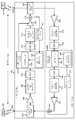
도 1은 주파수 분할 듀플렉스(FDD) 디지털 베이스밴드 간섭 소거 리피터를 사용하는 시스템의 블록 다이어그램이다.
도 2는 본 개시내용의 실시예에 따른 기지국 송수신기 시스템(BTS), 이동국(MS) 및 리피터 간의 전력 상호작용의 예를 도시하는 다이어그램이다.
도 3은 측정된 다운링크 RSSI 및 전력 제어 설정 포인트 값에 기초하여 업링크 이득을 제어할 수 있는 예시적인 FDD 디지털 베이스밴드 간섭 소거 리피터의 블록 다이어그램을 도시한다.
도 4는 측정된 다운링크 RSSI 및 전력 제어 설정 포인트 값에 기초하여 다운링크 이득을 제어하여 업링크 채널 상의 양자화를 위한 신호 레벨을 설정할 수 있는 예시적인 FDD 디지털 베이스밴드 간섭 소거 리피터의 블록 다이어그램이다.
도 5는 도 3에 도시된 리피터 및/또는 도 4에 도시된 리피터와 관련될 수 있는 예시적 프로세스의 흐름도이다.
도 6은 본 개시내용의 하나 또는 그 초과의 실시예들에 따라 다운링크 및/또는 업링크 이득들을 조정하도록 구성될 수 있는 리피터(600)의 구조 블록 다이어그램이다.BRIEF DESCRIPTION OF THE DRAWINGS The accompanying drawings are included to provide a further understanding of embodiments of the invention and are provided solely for illustration and not limitation.
1 is a block diagram of a system using a frequency division duplex (FDD) digital baseband interference cancellation repeater.
2 is a diagram illustrating an example of power interactions between a base station transceiver system (BTS), a mobile station (MS), and repeaters in accordance with an embodiment of the present disclosure.
3 shows a block diagram of an exemplary FDD digital baseband interference canceller repeater capable of controlling uplink gain based on measured downlink RSSI and power control set point values.
4 is a block diagram of an exemplary FDD digital baseband interference cancellation repeater capable of controlling the downlink gain based on the measured downlink RSSI and power control setpoint values to set the signal level for quantization on the uplink channel.
5 is a flow diagram of an exemplary process that may be associated with the repeater shown in FIG. 3 and / or the repeater shown in FIG.
6 is a structural block diagram of a
본 발명의 양상들은 본 발명의 특정 실시예들에 관해 후속하는 설명 및 관련 도면들에서 개시된다. 대안적인 실시예들이 본 발명의 범위로부터 벗어나지 않고 고안될 수 있다. 또한, 본 발명의 잘 알려진 엘리먼트들은 본 발명의 관련된 상세항목들을 모호하게 하지 않기 위해 상세하게 설명되지 않을 것이거나, 또는 생략될 것이다.Aspects of the present invention are disclosed in the following description of certain embodiments of the invention and the associated drawings. Alternate embodiments may be devised without departing from the scope of the present invention. In addition, well-known elements of the invention will not be described in detail or will be omitted so as not to obscure the relevant details of the invention.
용어 "예시적인"은 "예, 경우, 또는 예시로서 작용하는 것"을 의미하기 위해 본원에 사용된다. "예시적인" 것으로서 본원에 설명된 임의의 실시예는 반드시 다른 실시예들보다 바람직하거나 유리한 것으로 해석되지는 않는다. 마찬가지로, 용어 "본 발명의 실시예들"은 본 발명의 모든 실시예들이 논의된 특징, 장점 또는 동작 모드를 포함하는 것을 요구하지 않는다.The term "exemplary" is used herein to mean "serving as an example, instance, or illustration. &Quot; Any embodiment described herein as "exemplary " is not necessarily to be construed as preferred or advantageous over other embodiments. Likewise, the term "embodiments of the present invention" does not require that all embodiments of the invention include the features, advantages or mode of operation discussed.
본원에 사용되는 용어는 오직 특정 실시예들을 설명할 목적이며, 본 발명의 실시예들을 한정하도록 의도되지 않는다. 본원에 사용된 바와 같이, 단수 형태들("a," "an" 및 "the")은, 문맥이 달리 명백하게 지시하지 않는 한, 복수의 형태들 또한 포함하도록 의도된다. 용어들 "포함하다(comprises)", "포함하는(comprising)", "포함하다(includes)" 및/또는 "포함하는(including)"은, 본원에 사용되는 경우, 언급된 특징들, 정수들, 단계들, 동작들, 엘리먼트들 및/또는 컴포넌트들의 존재를 특정하지만, 하나 또는 그 초과의 다른 특징들, 정수들, 단계들, 동작들, 엘리먼트들, 컴포넌트들 및/또는 이들의 그룹들의 존재 또는 추가를 배제하지 않는다는 점이 추가로 이해될 것이다.The terminology used herein is for the purpose of describing particular embodiments only and is not intended to limit the embodiments of the invention. As used herein, the singular forms "a," "an," and "the" are intended to also include the plural forms, unless the context clearly dictates otherwise. The terms " comprises, "" comprising," " includes, " and / or "including ", when used in this specification, , Steps, operations, elements and / or components, but is not limited to the presence of one or more other features, integers, steps, operations, elements, components, and / Or < RTI ID = 0.0 > additions. ≪ / RTI >
또한, 많은 실시예들은 예를 들어, 컴퓨팅 디바이스의 엘리먼트들에 의해 수행될 동작들의 시퀀스들의 견지에서 설명된다. 본원에 설명된 다양한 동작들은 특정 회로들(예를 들어, 주문형 집적 회로(ASIC)들)에 의해, 하나 또는 그 초과의 프로세서들에 의해 실행되는 프로그램 명령들에 의해, 또는 이들 모두의 조합에 의해 수행될 수 있다는 점이 인지될 것이다. 추가로, 본원에 설명된 이러한 동작들의 시퀀스는, 실행시 연관된 프로세서로 하여금 본원에 설명된 기능을 수행하게 할 대응하는 컴퓨터 명령들의 세트가 저장되어 있는 임의의 형태의 컴퓨터 판독가능한 저장 매체 내에 완전히 구현되도록 고려될 수 있다. 따라서, 본 발명의 다양한 양상들은 다수의 다양한 형태들로 구현될 수 있고, 이들 모두는 청구 대상의 범위 내에 있는 것으로 참작된다. 추가로, 본원에 설명된 실시예들 각각에 대해, 임의의 이러한 실시예들의 대응하는 형태는, 예를 들어, 설명된 동작을 수행"하도록 구성되는 로직"으로서 본원에 설명될 수 있다.Further, many embodiments are described in terms of sequences of operations to be performed, for example, by elements of a computing device. The various operations described herein may be performed by specific circuits (e.g., application specific integrated circuits (ASICs)), by program instructions executed by one or more processors, or by a combination of both It will be appreciated that it can be performed. Additionally, the sequence of such operations described herein may be implemented in any form of computer readable storage medium having stored thereon a corresponding set of computer instructions for causing the associated processor to perform the functions described herein . Accordingly, it is to be understood that the various aspects of the present invention may be embodied in many different forms, all of which are within the scope of the claimed subject matter. Additionally, for each of the embodiments described herein, the corresponding form of any of these embodiments may be described herein as " logic configured to "perform, for example, the described operations.
개관survey
여기에 개시된 실시예들은 성능을 개선하고 리피터의 기지국에의 노이즈 기여(즉, 업링크 노이즈)를 관리하기 위해 리피터 내의 다양한 이득들을 제어하기 위해, 기지국으로부터 수신된 신호 레벨(다운링크 신호)의 측정치들 및 이동국의 표준 전력 제어에 통상적으로 사용되는 정보를 레버리징할 수 있는 리피터들에 관한 것일 수 있다.The embodiments disclosed herein provide a measure of the signal level (downlink signal) received from the base station to control various gains in the repeater to improve performance and manage the noise contribution (i.e., uplink noise) And repeaters capable of leveraging information typically used in standard power control of a mobile station.
예를 들어, 일 실시예에서, 업링크 채널에서의 리피터의 이득(즉, "업링크 이득")은 기지국의 수신기에서의 노이즈를 제어하기 위해 조정될 수 있다. 업링크 이득은 전력 제어 설정 포인트 파라미터(PC_SP) 및 기지국으로부터 송신되고 리피터에서 수신된 다운링크 신호의 RSSI 측정에 기초하여 조정될 수 있다.For example, in one embodiment, the gain of the repeater in the uplink channel (i.e., the "uplink gain") may be adjusted to control the noise at the base station's receiver. The uplink gain may be adjusted based on the power control set point parameter (PC_SP) and the RSSI measurement of the downlink signal transmitted from the base station and received at the repeater.
다른 실시예에서, 다운링크 채널 상의 리피터의 이득(즉, "다운링크 이득")은 업링크 채널 상의 리피터에서 다시 수신되는 신호의 레벨을 제어하기 위해 조정될 수 있다. 이 기술은 이동국에서 동작하는, 따라서 다운링크 채널 상에서 이동국이 수신하는 신호의 이득을 조정함으로써 이동국의 송신 신호 레벨의 출력을 (리피터에서) "원격으로" 제어하는, 전력 제어 시스템의 이점을 갖는다. 이러한 타입의 조정은 업링크 채널에서의 ADC에 의한 양자화를 위한 신호 레벨을 개선할 수 있고, 이는 성능을 개선하고 및/또는 ADC의 동적 범위 요건들을 완화하여 덜 비싼 ADC가 사용될 수 있도록 할 수 있다. 다운링크 이득은 전력 제어 설정 포인트 파라미터(PC_SP) 및 기지국으로부터 송신되고 리피터에서 수신된 신호(즉, 기지국으로부터의 다운링크 신호)의 RSSI 측정에 기초하여 조정될 수 있다.In another embodiment, the gain of the repeater on the downlink channel (i. E., The "downlink gain") can be adjusted to control the level of the signal received back at the repeater on the uplink channel. This technique has the advantage of a power control system that operates at the mobile station and therefore controls the output of the mobile station's transmit signal level (at the repeater) "remotely" by adjusting the gain of the signal received by the mobile station on the downlink channel. This type of adjustment can improve the signal level for quantization by the ADC in the uplink channel, which can improve performance and / or relax the dynamic range requirements of the ADC so that a less expensive ADC can be used . The downlink gain may be adjusted based on the power control set point parameter (PC_SP) and the RSSI measurement of the signal transmitted from the base station and received at the repeater (i.e., the downlink signal from the base station).
다른 실시예들에서, 전술한 이 기술들은 기지국에서의 업링크 노이즈를 완화시키고 또한 ADC 성능을 개선하기 위해 결합될 수 있다. 또 다른 실시예들에서, 이러한 기술들은 기지국에서의 업링크 노이즈 레벨들을 완화하면서 업링크 송신 전력을 개선하기 위해 간섭 소거 알고리즘들에 의해 사용되는 정보(예를 들어, RF 업링크/다운링크 기준 신호들)와 결합될 수 있다. 다양한 실시예들이 이하에 보다 상세히 제시된다.In other embodiments, the techniques described above may be combined to mitigate uplink noise at the base station and also to improve ADC performance. In other embodiments, such techniques may be used to reduce information used by interference cancellation algorithms (e. G., RF uplink / downlink reference signals < RTI ID = 0.0 >Lt; / RTI > Various embodiments are presented in more detail below.
간섭 소거 리피터들Interference cancellation repeaters
도 1은 주파수 분할 듀플렉스(FDD) 디지털 베이스밴드 간섭 소거 리피터(103)를 포함하는 무선 통신 시스템(100)의 블록 다이어그램이다. 리피터(103)는 기지국 송수신기 시스템(BTS)(105) 및 적어도 하나의 이동국(MS)(110)(도 1에는 단지 하나의 MS만 도시됨)과 신호들을 동시에 교환할 수 있다. BTS(105)로부터, 리피터(103)를 통해, MS(110)를 향해 이동하는 신호들은 "다운링크" 상에 있는 것으로 지칭된다. MS(110)로부터, 리피터(103)를 통해, BTS(105)를 향해 이동하는 신호들은 "업링크" 상에 있는 것으로 지칭된다. 리피터(103)는 각 디바이스에 대한 이득 또는 수신된 전력에 상관없이 양방향으로 가는 신호들을 증폭할 수 있다. 리피터(103)는 다운링크 및 업링크 사이의 고정 오프셋이 리피터(103)의 전체 이득을 설정하는데 사용될 수 있는 통상적인 이득 설정 어레인지먼트를 사용할 수 있다.FIG. 1 is a block diagram of a
리피터(103)는 수신된 주파수와 동일한 주파수 상에서 신호를 재송신할 수 있다. 주파수 분할 듀플렉스 리피터에서, 업링크 및 다운링크 신호들이 다른 주파수들에 중심을 두는 두 채널들에 의해 분리된다. 따라서, 리피터(103)는 분리된 업링크 및 다운링크 채널들을 사용하여 동시에 송신하고 수신할 수 있다. 도 1에서, 설명의 편의를 위해, 업링크 및 다운링크 채널들을 포함하는 블록들(120-150)이 결합된 양방향 경로에 도시되고, 여기서 실선 화살표들로 나타낸 왼쪽에서 오른쪽으로 가는 경로는 다운링크 채널을 나타내고, 점선 화살표들로 나타낸 오른쪽에서 왼쪽으로 가는 경로는 업링크 채널을 나타낸다.The
전체 리피터(103)가 인클로저에 수용되어 있고 안테나들(160 및 165)이 그 안에 통합된 어떤 구현 형태들에서, 안테나들(160, 165)이 리피터(103) 내에서 업링크 및 다운링크 채널들 사이의 충분한 격리를 제공하지 않을 수 있다. 안테나들(160 및 165) 사이에 존재하는 격리보다 이득이 더 요구되는 경우, 베이스밴드 간섭 소거가 리피터의 안정성을 증가시키고 전체 이득을 증가시키는데 사용될 수 있다. 이하에서 보다 상세히 설명될 바와 같이, 이는 디지털 프로세싱을 사용하여 피드백 채널(170) 상으로 제공되는 송신된 신호를 능동적으로 소거함으로써 성취될 수 있다.In some implementations in which a
동작 중에, 다운링크 신호가 BTS(105)에 의해 송신되고 이어서 안테나(160)에 의해 수신될 수 있다. 누설 신호가 또한 안테나(160)에 의해 수신되고, 이는 피드백 채널(170) 상으로 제공되고, 다운링크 신호 상에 겹쳐져서 결합된 신호를 생성한다. 듀플렉서(115)에 의해 결합된 신호가 분리된 업링크 및 다운링크 주파수 대역들로 필터링되고 적절한 다운링크 채널을 따라 라우팅될 수 있다. 결합된 신호는 증폭기(120) 및 아날로그 신호 프로세싱 블록(125)에 의해 아날로그 도메인에서 더 처리될 수 있다. 증폭기(120)는 저 노이즈 RF 증폭기를 사용하여 증폭을 제공할 수 있다. 아날로그 신호 프로세싱 블록(125)에서의 아날로그 프로세싱은 예를 들어 RF 표면 탄성파(SAW) 필터들을 사용한 필터링을 포함할 수 있다. 아날로그 신호 프로세싱 블록(125)은 또한 결합된 신호를 베이스밴드로 하향 변환하고, IQ 변환 및 에일리어스 차단을 위한 추가 필터링을 수행할 수 있다. 다음에 신호는 아날로그-투-디지털 변환기(ADC)(130)에 의해 디지털화될 수 있다.During operation, a downlink signal may be transmitted by the
피드백 채널(170)을 통해 수신된 누설 신호를 제거하기 위해 디지털화된 결합된 신호가 베이스밴드 프로세서(135)에 의해 프로세싱될 수 있다. 베이스밴드 프로세서(135)는 송신(Tx) 기준 신호에 적절한 채널 필터를 적용함으로써 누설 신호를 능동적으로 소거하여 예측되는 피드백 신호를 생성할 수 있다. 예측되는 피드백 신호가 결정되면, 이는 피드백 소거 블록(165)에서 베이스밴드 프로세서(135)에 의해 결합된 신호로부터 감산될 수 있다. 채널 필터가 피드백 채널 추정 블록(190)에서 생성될 수 있다.The digitized combined signal may be processed by the
다운링크 채널 경로를 더 참조하면, 채널 추정이 적절한 Tx 다운링크 기준 신호를 이용하여 결정될 수 있고, 이는 도 1에 도시된 실시예에서, RF 커플러(175)를 사용하여 증폭기(150)에 의한 증폭 후에 송신 신호를 분기(tapping)함으로써 획득될 수 있다. RF Tx 기준 수신기(180)는 RF 커플러(175)로부터 RF Tx 다운링크 기준 신호를 취하여 그 신호를 프로세싱(예를 들어, 하향 변환하거나 필터링하는 등)하고 디지털화하여, 그것이 피드백 채널 추정 블록(190)에 의한 사용을 위해 베이스밴드 프로세서(135)로 피드백될 수 있도록 한다. 피드백 채널 추정 블록(190)은 예를 들어 주파수 도메인 최소 평균 제곱 오차(minimum means square error: MMSE) 기술들을 사용하여 피드백 채널(170)의 채널 추정을 수행할 수 있다. 다운링크 신호에 겹쳐진 누설 신호는 베이스밴드 프로세서(135)에 의해 채널 추정을 디지털화된 RF Tx 다운링크 기준 신호와 컨벌빙하여 추정된 누설 신호를 획득함으로써 소거되고 제거될 수 있다. 추정된 누설 신호가 결정되면, 그것을 반전시키고(그것을 180도 위상 이동시키고) 그것을 결합된 신호에 합함으로써 추정된 누설 신호가 피드백 소거 블록(195)에서 결합된 신호로부터 소거될 수 있다.With further reference to the downlink channel path, the channel estimate may be determined using an appropriate Tx downlink reference signal, which in the embodiment shown in FIG. 1 is amplified by
다른 실시예들에서(미도시), 디지털화된 Tx 다운링크 기준 신호가 ADC/DAC(140)로부터 직접 획득될 수 있다. 그러나, 도시된 바와 같이 RF Tx 다운링크 기준 신호를 사용하는 것은 채널 추정 알고리즘들이 송신기 체인(예를 들어, ADC/DAC(140), 아날로그 신호 프로세서 블록(145), 증폭기(150) 등)의 컴포넌트들과 연관된 왜곡들을 포함하고 설명할 수 있도록 하는 이점들을 가질 수 있다. 이는 채널 추정의 정확도를 개선할 수 있고 따라서 간섭 소거를 개선할 수 있으며, 결과적으로 이는 증가된 격리로 인해 증폭기(150)로부터 송신되는 전력을 개선할 수 있다.In other embodiments (not shown), a digitized Tx downlink reference signal may be obtained directly from the ADC /
도 1 의 다운링크 채널을 더 참조하면, 일단 누설 신호가 제거되면, 다운링크 신호가 DAC/ADC(140)에 의해 아날로그 신호로 변환될 수 있다. 아날로그 신호는 아날로그 신호 프로세싱 블록(145)에 의해 아날로그 도메인에서 더 프로세싱될 수 있다. 아날로그 신호 프로세싱 블록(145)은 이미지 제거 필터링, IQ 상향-변환, 및 예를 들어 채널-사이의 간섭을 완화하기 위해 SAW 필터들을 사용하는, 추가의 RF 필터링을 포함할 수 있다. 마지막으로, RF 전력 증폭기(150)에 의해 전력 증폭이 제공될 수 있다. 그 이후에 증폭된 신호는 다운링크 및 업링크 채널들을 분리하기 위해 추가 필터링을 위한 듀플렉서/필터(155)로 전달되고 MS(110)로의 다운링크 송신을 위해 안테나(165)로 라우팅될 수 있다.With further reference to the downlink channel of FIG. 1, once the leakage signal is removed, the downlink signal can be converted to an analog signal by the DAC /
MS(110)에 의해 제공되는 업링크 신호들이 안테나(165)에 의해 동시에 수신될 수 있다. 전술한 다운링크 채널과 유사하게, 안테나(160)에 의해 송신된 피드백 채널(170)을 통해 제공된, 누설 신호가 안테나(165)에서 업링크 채널 상에 겹쳐진다. 결합된 신호가 듀플렉서/필터(155)에 제공되고, 이는 결합된 신호를 필터링하고 그 신호를 리피터의 적절한 업링크 채널 상으로 라우팅한다. 도 1에서, 업링크 채널은 점선들로 도시되고 다이어그램을 간략히 하기 위해 다운링크 채널과 같은 프로세싱 블록들을 공유한다. 업링크 채널에서 발생하는 프로세싱은 도 1에서 오른쪽에서 왼쪽으로인 반대 방향으로 진행하지만, 기본적으로 다운링크 채널에서 전술한 바와 동일할 수 있다. 업링크 채널은 채널 추정을 용이하게 하기 위해 분리된 RF Tx 업링크 기준 신호를 사용할 수 있는 분리된 피드백 채널 추정을 수행할 수 있다는 점에 주의해야 한다. RF Tx 업링크 기준은 RF 커플러(172)를 사용하여 증폭기(120) 출력을 분기(tap off)할 수 있다. 아날로그 RF 신호는 프로세싱 및 디지털화를 위해 RF Tx 기준 수신기(185)에 제공될 수 있다. 디지털화된 RF Tx 업링크 기준 신호는 다음에 베이스밴드 프로세서(135)로 제공되어 업링크 채널에 대한 피드백 채널이 피드백 채널 추정 블록(190)에 의해 추정될 수 있도록 한다. 다운링크 채널에 대해 전술한 방법과 유사하게, 업링크 채널에 대한 피드백 채널 추정은 안테나(165)를 통해 수신된 결합된 업링크 신호로부터 누설 신호를 제거하기 위한 채널 추정과 함께 사용될 수 있다.The uplink signals provided by the
리피터(103)에서, 리피터의 전체 이득이 증가됨에 따라 누설 신호가 비례하여 더 커진다. 이는 업링크 및 다운링크 채널들에서 결합된 신호의 동적 범위를 증가시킨다. 이는 비-선형 양자화 에러들/포화를 피하기 위해 더 높은 동적 범위를 갖는 아날로그-투-디지털 변환기들을 사용하는 것을 초래하고, 이는 리피터의 컴포넌트 비용들을 증가시킨다. 증가된 동적 범위는 또한 수신된 신호 둔감화를 초래할 수 있고, 송신기 출력 레벨들을 제한할 수 있으며, 기지국 수신기에 노이즈 기여를 증가시킬 수 있다.In the
리피터, BTS 및 MS 간의 전력 상호작용Power Interaction between Repeater, BTS and MS
여기에 기술된 실시예들은 수신된 다운링크 신호들의 측정된 전력 및 이동국들을 위한 통상의 전력 제어 기술들과 연관된 파라미터들에 기초하여 리피터 내의 다양한 이득들을 조정함으로써 증가된 동적 범위의 전술한 영향들을 감소시킬 수 있다. 예를 들어, 무선 표준들(예를 들어, CDMA, IS-2000, UMTS 등)에서 사용되는 전력 제어 기술들과 연관된 전력 제어 설정 포인트 파라미터들을 이용함으로써, 이동국으로부터 업링크 신호를 수신하기 전에 업링크 신호 전력의 계산이 결정될 수 있다. 여기서 사용된 바와 같이, 전력 제어 설정 포인트 파라미터는 MS(110)에 의해 업링크 채널을 통해 전송되는 송신의 신호 레벨(예를 들어, 전압, 전력, 진폭, 강도 등)을 설정하는데 사용될 수 있는 MS(110)에 제공되는 임의의 파라미터일 수 있다. 전력 제어 설정 포인트 값은 개 루프 설정 포인트 값, 폐 루프 설정 포인트 값, 또는 하나 또는 그 초과의 소스들로부터 제공되는 하나 이상의 다른 값(예를 들어, 데이터 채널들, 제어 채널들, 외부 디바이스들에 의해 제공되는 메시지들 또는 값들, 등), 또는 이들의 임의의 결합으로부터 직접 제공되거나 유도될 수 있는 임의의 다른 값일 수 있다. 이 정보는 리피터가 다운링크 채널의 하나 또는 그 초과의 증폭기들의 적절한 이득들을 설정하게 하도록 하고, 따라서 디지털화 전에 업링크 채널에서 결합된 신호의 동적 범위를 감소시킬 수 있다. 이러한 접근은 단일의 고정 동적 범위 구성을 갖는 리피터(103)의 제한들을 크게 완화할 수 있다. 추가로, 측정된 다운링크 신호 레벨로부터 유도된 정보는 디지털-투-아날로그 변환 이후에 적절한 증폭기(들)의 이득을 제어함으로써 업링크 노이즈 기여를 관리하는데 사용될 수 있다.The embodiments described herein reduce the aforementioned effects of increased dynamic range by adjusting various gains in the repeater based on the measured power of the received downlink signals and parameters associated with conventional power control techniques for mobile stations . For example, by using power control setpoint parameters associated with power control techniques used in wireless standards (e.g., CDMA, IS-2000, UMTS, etc.), uplink The calculation of the signal power can be determined. As used herein, the power control set point parameter may be used by the
도 2는 본 개시내용의 실시예에 따른 기지국 송수신기 시스템(BTS)(205), 이동국(MS)(215) 및 리피터(210) 사이의 전력 상호작용의 예를 도시하는 다이어그램이다. BTS(205) 및 MS(215) 사이의 전력 상호작용은 무선 통신 시스템들에서 사용되는 전력 제어 알고리즘들 때문에 "예측가능할"(즉, 실제 송신/수신 전에 분석적으로 결정될) 수 있고, 이하에서 설명되는 바와 같이, 이 예측 가능성은 리피터(210) 내의 다양한 이득들을 제어하기 위해 레버리징될 수 있다.FIG. 2 is a diagram illustrating an example of power interactions between a base station transceiver system (BTS) 205, a mobile station (MS) 215, and a
기지국 송수신기와 통신하는 모든 이동국들은 PN 코드의 사용을 통해 동일한 RF 대역을 공유하기 때문에 CDMA-기반 통신 시스템들에서 전력 제어는 매우 바람직하다. PN 코드들은 각 이동국의 신호를 RF 대역에 걸쳐 확산시키기 때문에, 각 이동국의 신호는 그 셀의 다른 이동국들에게 노이즈로서 나타난다. 따라서 각 이동국에 의해 송신되는 전력은 간섭을 피하기 위해 주의 깊게 제어되어야 한다. 이 제어는 기지국이 각 이동국에게 각 이동국과 기지국 사이의 신호 레벨들에 영향을 미치는 상태들의 변동들(예를 들어, 이동국(215)의 이동에 따른 거리 변화와 같은)을 보상하기 위해 그 송신되는 전력을 조정하도록 명령하게 함으로써 기지국에서 수신되는 전력을 균일하게 하려고 시도한다. 예를 들어, 기지국으로부터 더 먼 거리의 이동국은 기지국에 근접한 다른 이동국보다 더 높은 전력으로 송신하도록 명령 받을 것이다.Power control in CDMA-based communication systems is highly desirable because all mobile stations communicating with the base station transceiver share the same RF band through the use of PN codes. Since the PN codes spread the signal of each mobile station over the RF band, the signal of each mobile station appears as noise to other mobile stations of the cell. Thus, the power transmitted by each mobile station must be carefully controlled to avoid interference. This control is transmitted to compensate for variations (e.g., a change in distance as the
전력 제어와 연관된 파라미터들 및 리피터에서의 측정된다운링크 신호 레벨(예를 들어, RSSI)이 이동국으로부터 리피터에서 수신된업링크 송신 전력 및 리피터(210)로부터 기지국 단말 시스템(BTS)(205)으로 송신된업링크 전력 둘 다를 계산하는데 어떻게 사용될 수 있는지를 도시하기 위해, 하나의 이동국(MS)(215), 리피터(210) 및 기지국 시스템(BTS) 사이의 전력 상호작용을 도시하는 모델이 도 2에 제공된다. 도 2에 도시된 바와 같이, BTS(205)에 의해 송신되는 다운링크 신호(206)는 리피터(210)에서의 수신된 신호 강도 표시자(Received Signal Strength Indicator: RSSI) 값(RSSI_RPTDL)을 낳는다. 리피터(210)는 이 수신된 신호를 증폭하고 MS(215)에 다운링크 신호(212)를 재-송신할 것이다. 리피터에 의해 재-송신된 신호의 전력(Power TX_RPTDL)은 다음과 같이 양자화될 수 있다:The parameters associated with power control and the measureddownlink signal level (e.g., RSSI) at the repeater are transmitted from the mobile station to theuplink transmit power received from the repeater and from the
Power TX_RPTDL = RSSI_RPTDL + GRPT,Power TX_RPTDL = RSSI_RPTDL + GRPT ,
여기서 GRPT는 리피터의 이득이다.Where GRPT is the gain of the repeater.
MS(215)에서, 수신된 신호의 RSSI(RSSI_MS)는 다음과 같이 설명될 수 있다:At the
RSSI_MS = RSSI_RPTDL + GRPT - PL,RSSI_MS = RSSI_RPTDL + GRPT - PL,
여기서 PL은 리피터(210) 및 MS(215) 사이의 신호 경로 손실이다.Where PL is the signal path loss between
이동국에서 사용되는 전력 제어 룰들 때문에, 이동국은 다음 식에 기초한 전력을 갖는 그 업링크 신호(216)를 송신할 것이다:Because of the power control rules used in the mobile station, the mobile station will transmit its
Power TXMS = PC_SP - RSSI_MSPower TXMS = PC_SP - RSSI_MS
= PC_SP - RSSI_RPTDL - GRPT + PL,= PC_SP - RSSI_RPTDL - GRPT + PL,
여기서, PC_SP 값은 전력 제어 설정 포인트이고, 사용되는 전력 제어 알고리즘에 기초할 수 있다.Here, the PC_SP value is a power control set point and can be based on the power control algorithm used.
PC_SP 값은 사용되는 네트워크 표준의 타입(예를 들어, IS-2000, WCDMA, LTE, UMTS 등)과 같은 다양한 다른 상태들에 의존할 수 있음에 주의해야 한다. 추가로, PC_SP는 또한 MS(215)가 그 동작 모드에 기초하여 사용하고 있는 송신 파라미터들에 따라 변할 수 있다. 예를 들어, IS-2000 시스템에서, PC_SP는 대역 계층, 확산 레이트, 역 채널들의 상태 등에 기초하여 변할 수 있다. 일 실시예에서, 리피터는 BTS(205)에 의해 송신되는 제어 채널들을 디코딩함으로써 그 값을 추출할 수 있다.It should be noted that the PC_SP value may depend on various other states such as the type of network standard used (e.g., IS-2000, WCDMA, LTE, UMTS, etc.). Additionally, the PC_SP may also vary depending on the transmission parameters that the
도 2를 더 참조하면, 업링크(216)의 반대 측에서, 리피터는 다음 RSSI 값(RSSI_RPTUL)으로 이동국(215)에 의해 송신되는 신호를 수신할 것이다:2, on the opposite side of the
RSSI_RPTUL = Power TXMS - PLRSSI_RPTUL = Power TXMS -PL
= PC_SP - RSSI_RPTDL - GRPT.= PC_SP - RSSI_RPTDL - GRPT .
(리피터(210) 및 이동국(215) 사이의 경로 손실이 소거되었다는 점에 주의해야 한다.)(Note that the path loss between the
업링크 신호(216)가 리피터(210)에 의해 수신된 이후에, 리피터(210)는 다음 전력(Power TX_RPTUL)을 갖는 업링크 신호(218)를 송신할 수 있다:After the
Power TX_RPTUL = RSSI_RPTUL + GRPTPower TX_RPTUL = RSSI_RPTUL + GRPT
= PC_SP - RSSI_RPTDL.= PC_SP - RSSI_RPTDL .
위 식들로부터, 리피터에서 수신된 업링크 RSSI(RSSI_PPTUL)는 리피터에서 나타난 다운링크 RSSI(RSSI_RPTDL), MS(215)에 의해 사용되는 PC_SP 값 및 리피터(210) 이득(GRPT)으로부터 예측될 수 있음을 볼 수 있다. 더욱이 리피터(210)에 의해 BTS(205)로 송신되는 업링크 전력(Power TX_RPTUL)은 동일한 방법으로 예측될 수 있다.From the above equations, the uplink RSSI (RSSI_PPTUL ) received at the repeater may be predicted from the downlink RSSI (RSSI_RPTDL ) indicated in the repeater, the PC_SP value used by the
이는 기지국에서의 전력을 균등하게 하고 기지국과 이동 단말기들 사이의 변화하는 거리들을 보상하기 위한, 전력 제어 룰들의 목적으로부터 직관적으로 알 수 있다. 전력 제어 룰들에 기초하여, 기지국에 의해 송신되는 다운링크 신호의 RSSI가 높다면, 이동국과 기지국 사이의 거리가 작다고 추정될 수 있고, 따라서 이동국은 그들의 상대적 근접을 보상하기 위해 업링크 상에서 기지국으로 다시 더 낮은 전력을 송신할 것으로 예측될 수 있음이 일반적으로 추론될 수 있다. 반대로, 다운링크 신호의 RSSI가 낮다면, 이동국과 기지국이 서로 멀리 떨어져 있다고 추정될 수 있고, 따라서 이동국은 더 먼 거리를 보상하기 위해 업링크 상에서 기지국으로 다시 더 높은 전력을 송신할 것으로 예측될 수 있음이 추론될 수 있다.This is intuitively known from the purposes of power control rules for equalizing the power at the base station and for compensating for the varying distances between the base station and the mobile terminals. Based on the power control rules, if the RSSI of the downlink signal transmitted by the base station is high, the distance between the mobile station and the base station may be estimated to be small, and thus the mobile station may return to the base station on the uplink to compensate for their relative proximity It can be generally deduced that it can be expected to transmit lower power. Conversely, if the RSSI of the downlink signal is low, it can be assumed that the mobile station and the base station are far apart from each other, and thus the mobile station can be expected to transmit higher power back to the base station on the uplink to compensate for the longer distance Can be deduced.
업링크 RSSI는 리피터에서 이동국으로의 경로 손실에 독립적임을 또한 알 수 있다(페이딩을 무시하며, 이는 고속 폐루프 전력 제어에 의해 제어될 수 있다).It can also be seen that the uplink RSSI is independent of the path loss from the repeater to the mobile station (ignoring fading, which can be controlled by fast closed loop power control).
여기에서 사용된 바와 같이, MS(215)는 셀룰러 또는 다른 무선 통신 디바이스, 개인 통신 시스템(PCS) 디바이스, 개인 네비게이션 디바이스(PND), 개인 정보 관리자(PIM), 개인 휴대 정보 단말(PDA), 랩탑 또는 무선 통신 및/또는 네비게이션 신호들을 수신할 수 있는 다른 적합한 이동 디바이스와 같은 디바이스로 지칭될 수 있다. 용어 "이동국"은 또한, 디바이스에서 또는 PND에서 위성 신호 수신이 발생하든지, 보조 데이터 수신이 발생하든지, 및/또는 포지션-관련 프로세싱이 발생하든지와 무관하게, 예를 들어, 단거리 무선, 적외선, 유선 접속 또는 다른 접속에 의해 개인 네비게이션 디바이스(PND)와 통신하는 디바이스들을 포함하도록 의도된다. 또한, "이동국"은, 디바이스에서, 서버에서, 또는 네트워크와 연관된 다른 디바이스에서 위성 신호 수신이 발생하든지, 보조 데이터 수신이 발생하든지, 및/또는 포지션-관련 프로세싱이 발생하든지와 무관하게, 예를 들어, 인터넷, WiFi 또는 다른 네트워크를 통해 서버와 통신할 수 있는, 무선 통신 디바이스들, 컴퓨터들, 랩탑들 등을 포함하는 모든 디바이스들을 포함하도록 의도된다. 상기한 것들의 임의의 동작가능한 조합이 또한 "이동국"으로 고려된다.As used herein,
BTS(205)는 복수의 PCS/셀룰러 통신 셀-사이트들을 포함하는 지상 기반의 통신 시스템들 및 네트워크들의 부분일 수 있다. 그들은 CDMA 또는 TDMA 타입의 신호들을 원격 국들로 또는 원격 국들로부터 전송하는, CDMA 또는 TDMA(또는 하이브리드 CDMA/TDMA) 디지털 통신 시스템들과 연관될 수 있다. 신호들은 WCDAM, CDMA2000 또는 TD-SCDMA 타입의 신호들을 사용하는, IMT-2000/UMTS 표준들에 따라 포맷될 수 있다. 한편, BTS(205)는 아날로그 기반의 통신 시스템(AMPS와 같은)과 연관되고 아날로그 기반의 통신 신호들을 전송할 수 있다.The
여기에 기술된 실시예들은 WWAN(wide area wireless network), WLAN(wireless local area network), WPAN(wireless personal area network) 등과 같은 다양한 무선 통신 네트워크들과 함께 구현될 수 있다. 용어 "네트워크" 및 "시스템"은 종종 상호 교환 가능하게 사용될 수 있다. WWAN은 CDMA(Code Division Multiple Access) 네트워크, TDMA(Time Division Multiple Access) 네트워크, FDMA(Frequency Division Multiple Access) 네트워크, OFDMA(Orthogonal Frequency Division Multiple Access) 네트워크, SC-FDMA(Single-Carrier Frequency Division Multiple Access) 네트워크, LTE(Long Term Evolution) 등일 수 있다. CDMA 네트워크는 cdma2000, 광대역-CDMA(W-CDMA) 등과 같은 하나 또는 그 초과의 라디오 액세스 기술(RAT)들을 구현할 수 있다. cdma2000은 IS-95, IS-2000 및 IS-856 표준들을 포함한다. TDMA 네트워크는 GSM(Global System for Mobile Communications), D-AMPS(Digital Advanced Mobile Phone System), 또는 몇몇의 다른 RAT를 구현할 수 있다. GSM 및 W-CDMA는 "3GPP(3rd Generation Partnership Project)"로 명명된 컨소시엄으로부터의 문헌들에 설명된다. cdma2000은 "3GPP2(3rd Generation Partnership Project 2)"로 명명된 컨소시엄으로부터의 문헌들에 설명된다. 3GPP 및 3GPP2 문헌들은 공개적으로 이용 가능하다. WLAN은 IEEE 802.11x 네트워크일 수 있고, WPAN은 블루투스 네트워크, IEEE 802.15x, 또는 몇몇의 다른 형태의 네트워크일 수 있다. 상기 기술들은 또한 WWAN, WLAN 및/또는 WPAN의 임의의 조합과 함께 구현될 수 있다.The embodiments described herein may be implemented with various wireless communication networks such as a wide area wireless network (WWAN), a wireless local area network (WLAN), a wireless personal area network (WPAN), and the like. The terms "network" and "system" are often used interchangeably. The WWAN may be a Code Division Multiple Access (CDMA) network, a Time Division Multiple Access (TDMA) network, a Frequency Division Multiple Access (FDMA) network, an Orthogonal Frequency Division Multiple Access (OFDMA) network, a Single- ) Network, Long Term Evolution (LTE), and the like. A CDMA network may implement one or more radio access technologies (RATs) such as cdma2000, Wideband-CDMA (W-CDMA), and the like. cdma2000 includes IS-95, IS-2000, and IS-856 standards. The TDMA network may implement Global System for Mobile Communications (GSM), Digital Advanced Mobile Phone System (D-AMPS), or some other RAT. GSM and W-CDMA are described in documents from a consortium named "3rd Generation Partnership Project (3GPP) ". cdma2000 is described in documents from a consortium named "3rd Generation Partnership Project 2 (3GPP2) ". 3GPP and 3GPP2 documents are publicly available. The WLAN may be an IEEE 802.11x network, and the WPAN may be a Bluetooth network, IEEE 802.15x, or some other type of network. The techniques may also be implemented with any combination of WWAN, WLAN, and / or WPAN.
리피터 이득 제어: BTS에서의 노이즈 기여 완화Repeater gain control: To mitigate noise contribution in the BTS
측정된 다운링크 RSSI 및 MS의 전력 제어 설정 포인트로부터 결정될 수 있는 정보를 레버리징함으로써, 리피터의 업링크 상의 이득을 적절히 설정하여 BTS에서의 리피터의 노이즈 기여를 감소시킬 수 있다. 도 3은 측정된 다운링크 RSSI 및 전력 제어 설정 포인트 값에 기초하여 업링크 이득을 제어할 수 있는 예시적인 FDD 디지털 베이스밴드 간섭 소거 리피터(300)의 블록 다이어그램을 도시한다.By leveraging the measured downlink RSSI and information that can be determined from the power control set point of the MS, the gain on the repeater's uplink can be set appropriately to reduce the noise contribution of the repeater in the BTS. 3 shows a block diagram of an exemplary FDD digital baseband
리피터(300)는 안테나(302)에서 BTS(305)로부터 다운링크 신호를 그리고 안테나(322)로부터 누설 신호를 수신할 수 있다. 결합된 다운링크 신호는 필터링 및 신호들의 적절한 스위칭을 수행하여 다운링크 및 업링크 신호들을 분리할 수 있는 듀플렉서/필터(304)에 제공될 수 있다. 수신된 다운링크 신호의 경우, 듀플렉서/필터(304)는 결합된 신호를 다운링크 채널로 라우팅할 것이다. 결합된 다운링크 신호는 그 이득을 증가시키기 위해 저 노이즈 증폭기(306)에 의해 증폭될 수 있다. 결합된 다운링크 신호는 아날로그 신호 프로세싱 블록(308)에 의해 아날로그 도메인에서 더 프로세싱될 수 있다. 아날로그 프로세싱은 예를 들어 RF 표면 탄성파(SAW) 필터들을 사용한 필터링, 베이스밴드로의 하향 변환, IQ 변환 수행 및 에일리어스 차단을 위한 추가 필터링을 포함할 수 있다. 다음에 결합된 다운링크 신호는 아날로그-투-디지털 변환기(ADC)(310)에 의해 디지털화될 수 있다.The
디지털화된 결합된 다운링크 신호는 베이스밴드 프로세서(312)에 의해 프로세싱되어 피드백 채널을 통해 수신된 누설 신호를 제거할 수 있다. 베이스밴드 프로세서(312)는 송신(Tx) 기준 신호에 적절한 채널 필터를 적용함으로써 누설 신호를 능동적으로 소거하여 예측되는 피드백 신호를 생성할 수 있다. 예측되는 피드백 신호가 결정되면, 그것은 베이스밴드 프로세서(312)에 의해 결합된 다운링크 신호로부터 감산될 수 있다. 채널 필터가 피드백 채널 추정 블록(326)에서 생성될 수 있다.The digitized combined downlink signal may be processed by the
다운링크 채널 경로를 더 참조하면, 피드백 채널 추정은 RF 커플러(319)를 사용하여 RF 증폭기(318)에 의한 증폭 후에 송신 신호를 분기(tapping)함으로써 획득될 수 있는 적절한 Tx 다운링크 기준 신호를 이용하여 결정될 수 있다. RF Tx 기준 수신기(323)는 커플러(319)로부터 RF Tx 다운링크 기준 신호를 취하여 그 신호를 프로세싱(예를 들어, 하향 변환하거나 필터링하는 등)하고 디지털화하여, 그것이 피드백 채널 추정 블록(326)에 의한 사용을 위해 베이스밴드 프로세서(312)로 피드백될 수 있도록 한다. 피드백 채널 추정 블록(326)은 예를 들어 주파수 도메인 최소 평균 제곱 오차(minimum means square error: MMSE) 기술들을 사용하여 피드백 채널의 채널 추정을 수행할 수 있다. 다운링크 신호에 겹쳐진 누설 신호는 베이스밴드 프로세서(312)에 의해 채널 추정을 디지털화된 RF Tx 다운링크 기준 신호와 컨벌빙하여 추정된 누설 신호를 획득함으로써 소거되고 제거될 수 있다. 추정된 누설 신호가 결정되면, 상기 누설 신호는 그것을 180도 위상 이동시키고 그것을 결합된 신호에 합함으로써 피드백 소거 블록(324)에서 결합된 다운링크 신호로부터 소거될 수 있다.With further reference to the downlink channel path, the feedback channel estimation uses an appropriate Tx downlink reference signal that can be obtained by tapping the transmit signal after amplification by the
다른 실시예들에서(미도시), 디지털화된 Tx 다운링크 기준 신호는 ADC(310)로부터 직접 획득될 수 있다. 그러나, 도시된 바와 같이 RF Tx 다운링크 기준 신호를 사용하는 것은 채널 추정 알고리즘들이 송신기 체인(예를 들어, DAC(314), 아날로그 신호 프로세싱 블록(316), RF 증폭기(318), RF 커플러(319) 등)의 컴포넌트들과 연관된 왜곡들을 포함하고 설명할 수 있도록 하는 이점들을 가질 수 있다. 이는 채널 추정의 정확도를 개선할 수 있고 따라서 간섭 소거를 개선할 수 있으며, 결과적으로 이는 증가된 격리로 인해 RF 증폭기(318)로부터 송신되는 전력을 개선할 수 있다.In other embodiments (not shown), the digitized Tx downlink reference signal may be obtained directly from
도 3의 다운링크 채널을 더 참조하면, 일단 누설 신호가 제거되면, 다운링크 신호는 DAC(314)에 의해 아날로그 신호로 변환될 수 있다. 아날로그 신호는 아날로그 신호 프로세싱 블록(316)에 의해 아날로그 도메인에서 더 프로세싱될 수 있다. 아날로그 신호 프로세싱 블록(316)은 이미지 제거 필터링, IQ 상향-변환, 및 예를 들어 채널-사이의 간섭을 위한 SAW 필터들을 사용하는 추가의 RF 필터링을 포함할 수 있다. 마지막으로, RF 증폭기(318)에 의해 전력 증폭이 제공될 수 있다. 그 이후에 증폭된 다운링크 신호는 다운링크 및 업링크 채널들을 분리하기 위해 추가 필터링을 위한 듀플렉서/필터(320)로 전달되고 MS(315)로의 다운링크 송신을 위해 안테나(322)로 라우팅될 수 있다.With further reference to the downlink channel of FIG. 3, once the leakage signal is removed, the downlink signal can be converted to an analog signal by the
베이스밴드 프로세서(312)는 업링크 RF 증폭기(342) 상의 이득을 변경할 수 있는 제어 신호를 더 생성할 수 있다. 위에서 설명한 바와 같이, 업링크 채널 상의 이득은 측정된 다운링크 RSSI 및 MS의 전력 제어 설정 포인트에 기초하여 설정될 수 있다. 이러한 값들을 알면, 베이스밴드 프로세서(312)는 그 안에 구현된 룩업 테이블들, 로직, 및/또는 모델들에 기초하여 제어 신호를 생성할 수 있다. 일 실시예에서, 베이스밴드 프로세서(312)는 누설 신호가 제거된 뒤에 BTS(305)로부터의 디지털화된 다운링크 신호로부터 RSSI를 디지털적으로 계산할 수 있다. 전력 제어 설정 포인트는 BTS(305)에 의해 제공된 제어 채널로부터 베이스밴드 프로세서(312)에 의해 판독될 수 있다. 다른 실시예들에서, 전력 제어는 다른 방법들로 결정될 수 있고, 이는 이하의 도 5의 설명에서 보다 상세하게 제공될 것이다. 업링크 RF 증폭기(342)의 이득을 조정함으로써, 듀플렉서(304) 및 안테나(302)를 통해 기지국으로 다시 송신되는 업링크 신호 레벨이 감소될 수 있고, 따라서, BTS(305)의 수신기에서 보이는 노이즈 플로어(Rise over Thermal - RoT)에의 리피터(300)의 기여를 감소시킬 수 있다. 다른 실시예들에서, 베이스밴드 프로세서는 업링크 채널 상의 이득을 다른 방법들로 조정할 수 있다. 예를 들어, 베이스밴드 프로세서(336)는 업링크 채널에서 이득을 디지털적으로 조정하도록 명령받을 수 있거나, 또는 다른 증폭기들이 이득을 조정하는데 사용될 수 있다. 마지막으로, 일 실시예에서, 베이스밴드 프로세서(312)는 추가로 RF Tx 기준 신호를 사용하여 업링크 송신 전력을 더 개선한다. 상기 주의된 바와 같이, RF Tx 기준 신호의 사용은 신호 체인의 더 많은 엘리먼트들을 설명함으로써 더 양호한 간섭 소거를 허용하고, 따라서 선형 및 비선형 둘 다의 다양한 컴포넌트 아티팩트(artifact)들이 제거되어 리피터의 전체 노이즈 플로어를 더 감소시키고 소거를 개선하며, 따라서 리피터가 더 많은 전력을 송신하도록 허용할 수 있다.The
MS(315)에 의해 제공되는 업링크 신호들이 안테나(322)에 의해 동시에 수신될 수 있다. 전술한 다운링크 채널과 유사하게, 안테나(302)에 의해 송신된 피드백 채널(170)을 통해 제공된, 누설 신호가 안테나(322)에서 업링크 채널 상에 겹쳐진다. 결합된 업링크 신호를 필터링하고 리피터(300)에서 그 신호를 적절한 업링크 채널 상으로 라우팅하는 듀플렉서/필터(320)에 결합된 업링크 신호가 제공된다. 결합된 업링크 신호는 저 노이즈 증폭기(330), 아날로그 신호 프로세싱 블록(332), 및 ADC(334)로 전달될 수 있고, 이는 업링크 신호에 다운링크 채널의 저 노이즈 증폭기(306), 아날로그 신호 프로세싱 블록(308), 및 ADC(310)의 대응 블록들과 유사한 기능들을 수행한다. 다음에 디지털화된 결합된 업링크는 베이스밴드 프로세서(336)로 제공될 수 있고, 이는 분리된 피드백 채널 추정을 수행할 수 있고 채널 추정을 용이하게 하기 위해 분리된 RF Tx 업링크 기준 신호를 사용할 수 있다. RF Tx 업링크 기준은 RF 커플러(348)를 사용하여 RF 증폭기(342)의 출력을 분기(tap off)할 수 있다. 아날로그 RF 신호는 프로세싱 및 디지털화를 위해 RF Tx 기준 수신기(337)에 제공될 수 있다. 디지털화된 RF Tx 업링크 기준 신호는 다음에 베이스밴드 프로세서(336)로 제공되어 업링크 채널을 위한 피드백 채널이 피드백 채널 추정 블록(346)에 의해 추정될 수 있도록 할 수 있다. 다운링크 채널에 대해 전술한 방법과 유사하게, 업링크 채널에 대한 피드백 채널 추정은 안테나(322)를 통해 수신된 결합된 업링크 신호로부터 베이스밴드 프로세서(336)에서, 피드백 소거 블록(344)을 사용하여, 누설 신호를 제거하기 위한 채널 추정과 함께 사용될 수 있다. 일단 누설 신호가 제거되면, 업링크 신호는 DAC(338)에 의해 아날로그 신호로 변환되고, 아날로그 신호 프로세싱 블록(340)에서 더 프로세싱되고, 그리고 안테나(302)에 의한 송신 전에 RF 증폭기(342)에 의해 증폭될 수 있다.The uplink signals provided by
도 3에서, 다운링크 채널과 업링크 채널은 각각 분리된 베이스밴드 프로세서들(312 및 336)을 갖는 것으로 도시되었다. 이들 프로세서는 물리적으로 분리되어 있거나 같은 패키지 내에 함께-위치하고 있을 수 있음에 주의해야 한다. 대안적으로, 어떤 실시예들에서, 오로지 하나의 베이스밴드 프로세서가 업링크 및 다운링크 채널 둘 다에 대한 채널 추정 및 피드백 소거를 수행하는데 사용될 수 있다.In Figure 3, the downlink and uplink channels are shown to have
다양한 실시예들이 FDD 디지털 베이스밴드 리피터들에 한정되지 않으며, 여기에 기술된 이득 제어 접근들이 다른 타입들의 리피터들과 함께 사용될 수 있음이 이해되어야 한다. 더욱이, 도 3에 도시된 실시예에서, 직접 변환 수신기 또는 zero-IF 수신기 아키텍처가 수신기 회로를 구현하는데 사용된다. 다른 실시예들에서, 다른 수신기 아키텍처가 사용될 수 있다. 수신기 아키텍처의 정확한 구현은 본 발명의 실시에 결정적이지 않다.It should be understood that the various embodiments are not limited to FDD digital baseband repeaters, and that the gain control approaches described herein may be used with other types of repeaters. Moreover, in the embodiment shown in Figure 3, a direct conversion receiver or zero-IF receiver architecture is used to implement the receiver circuitry. In other embodiments, other receiver architectures may be used. The precise implementation of the receiver architecture is not critical to the practice of the present invention.
리피터Repeater 이득 제어: Gain control:ADCADC를 위한 신호 레벨들의 제어Control of signal levels for
측정된 다운링크 RSSI, MS의 전력 제어 설정 포인트, 및 전체 리피터 이득(GRPT)으로부터 결정될 수 있는 정보를 레버리징함으로써, 리피터는 MS에 의해 송신된 리피터에서 업링크 상으로 수신된 신호의 레벨을 적절히 계산할 수 있다. 이 정보는 업링크 채널 상에서 리피터로 다시 수신된 신호의 레벨을 제어하기 위해 리피터의 다운링크 상의 이득을 설정하는데 사용될 수 있다. 따라서 리피터는 다운링크 채널 상에서 이동국이 수신하는 신호의 이득을 조정함으로써 이동국의 송신 신호 레벨의 출력을 "원격으로" 제어할 수 있다. 이 타입의 조정은 업링크 채널에서 ADC에 의한 양자화를 위한 신호 레벨을 개선할 수 있고, 이는 성능을 개선하고 및/또는 ADC의 동적 범위 요건들을 완화할 수 있고, 따라서 덜 비싼 ADC가 사용될 수 있도록 한다.By levering the information that can be determined from the measured downlink RSSI, the MS's power control setpoint, and the total repeater gain (GRPT ), the repeater determines the level of the signal received on the uplink in the repeater transmitted by the MS Can be calculated properly. This information can be used to set the gain on the downlink of the repeater to control the level of the signal received back to the repeater on the uplink channel. Thus, the repeater can "remotely" control the output of the transmission signal level of the mobile station by adjusting the gain of the signal received by the mobile station on the downlink channel. This type of tuning can improve the signal level for quantization by the ADC in the uplink channel, which can improve performance and / or mitigate the dynamic range requirements of the ADC, thus allowing a less expensive ADC to be used do.
도 4는 측정된 다운링크 RSSI 및 업링크 채널 상에서 양자화를 위한 신호 레벨을 설정하기 위한 전력 제어 룰들에 기초하여 다운링크 이득을 제어할 수 있는 예시적인 FDD 디지털 베이스밴드 간섭 소거 리피터(400)의 블록 다이어그램이다. 도 4에 도시된 리피터(400)는 도 3에 도시된 리피터(300)와 유사한 컴포넌트들을 공유할 수 있고, 이는 도 3의 설명에서 전술한 바와 유사한 방법으로 동작할 수 있다. 따라서, 유사한 컴포넌트들은 동일한 참조 번호들을 공유할 것이고, 간결함을 위해, 리피터(400)와 리피터(300) 사이의 차이점들만이 후술된다.4 is a block diagram of an exemplary FDD digital baseband
리피터(400)에서, 베이스밴드 프로세서(312)는 다운링크 채널 상의 RF 증폭기(318)의 이득을 조정하여 다운링크를 통해 MS(315)에 송신되는 신호의 레벨을 변경할 수 있다. 이 이득 조정은 베이스밴드 프로세서(312)에서 다운링크 RSSI를 측정함으로써, 그리고 MS(315)의 전력 제어와 연관된 전력 제어 설정 포인트를 결정함으로써 결정될 수 있다. 리피터(400)의 전체 이득과 함께, 이들 값들을 사용하여, 업링크 상의 리피터에서의 신호 레벨이 결정될 수 있다. 이 레벨을 결정함으로써, 베이스밴드 프로세서(312)는 RF 증폭기(318) 상의 이득을 변경하여 MS(315)가 업링크 상에서 그 송신되는 신호의 레벨을 변경하도록 구동할 수 있다. 이는 업링크 ADC(334)에 의한 디지털화를 위해 업링크 신호를 더 잘 스케일링할 수 있도록 업링크 채널 상의 동적 범위를 시프팅할 수 있다. 이 기술은 양자화 및/또는 포화 노이즈를 감소할 수 있도록 업링크 신호의 동적 범위를 감소시키는데 사용될 수 있다. 더욱이, 이는 더 낮은 동적 범위를 갖는 ADC(334)의 사용을 허용할 수 있고, 이는 ADC의 비용을 줄여줄 수 있다. 추가로, RF Tx 다운링크 기준은 또한 전체 업링크 송신 전력을 증가시키도록 개선된 동적 범위와 함께 사용될 수 있다. 베이스밴드 프로세서(312)는 그 안에 구현된 룩업 테이블들, 로직, 및/또는 모델들에 기초하여 RF 증폭기(318)를 구동하는데 사용되는 제어 신호를 생성할 수 있다.In the
이득 제어 기술들의 결합Combination of gain control techniques
다른 실시예에서, 리피터(300)에서 사용되는 업링크 이득 제어 및 리피터(400)에서 사용되는 다운링크 이득 제어가 결합되어 리피터의 전체 성능을 개선할 수 있고, 따라서 리피터의 업링크 상에서 동적 범위 및 전체 송신 전력을 개선함과 함께 기지국에서 열 노이즈를 완화할 수 있다. 이 베이스밴드 프로세서(312)는 리피터의 성능을 최적화하기 위해 양 이득들을 가장 잘 선택하는 추가의 로직들을 이용할 수 있다. 이 로직은 최적화를 수행하기 위해 BTS(305)에 의해 제공된 정보를 이용할 수 있다. 예를 들어, BTS(305)는 리피터로부터의 신호를 분석하고 성능지수들(예를 들어, 신호 대 노이즈 비율, 에러 백터 크기, 예측 데이터 레이트들, 등)을 결정하고, 리피터가 얼마나 잘 동작하는지에 관해 제어 채널, 데이터 채널 및/또는 SMS 메시지를 통해 리피터에 명령들을 제공할 수 있다. 리피터의 로직은 리피터의 전체 동작을 개선하기 위해 이 피드백 정보를 사용하여 다운링크 및/또는 업링크 이득들의 조정들을 개량할 수 있다.In another embodiment, the uplink gain control used in the
도 5는 도 3에 도시된 리피터(300) 및/또는 도 4에 도시된 리피터(400)와 관련될 수 있는 예시적 프로세스(500)의 흐름도이다. 이 프로세스는 MS(315)의 전력 제어 설정 포인트 값을 결정함으로써 시작할 수 있다(블록 505). 전술한 바와 같이, 전력 제어 설정 포인트 값은 업링크 상에서 MS(315)에 의해 송신되는 신호의 전력을 제어한다. 전력 제어 설정 포인트 값은, 예를 들어, 제어 채널을 통해 및/또는 BTS(305)에 의해 제공되는 데이터 채널의 메시지들로부터 판독될 수 있다. 다수의 BTS(305) 신호들이 수신될 때에, 다수의 전력 제어 설정 포인트 값들이 특정 기지국과 연관되거나 이후의 사용을 위해 저장될 수 있다. 대안적으로, 전력 제어 설정 포인트 값의 결정은 후술하는 바와 같이 RSSI 신호를 측정하는 것과 함께 결정될 수 있다. 대안적인 실시예에서, 전력 제어 설정 포인트 값은 상이한 네트워크 표준들(예를 들어, IS-2000, W-CDMA, LTE 등)에 기초하여 리피터들에 미리 프로그래밍될 수 있다. 또 다른 실시예에서, 전력 제어 설정 포인트 값은 데이터 채널을 통해 및/또는 SMS(Simple Messaging Service)와 같은 다른 메시징 프로토콜을 사용하여 BTS(305)에 의해 제공될 수 있다. 이 경우에, BTS(305)는 예를 들어 Rise over Thermal 노이즈가 적절히 관리됨을 보증할 수 있도록 하나 이상의 리피터들을 동적으로 제어할 수 있다.FIG. 5 is a flow diagram of an
다음으로, 리피터는 안테나(302)에서 BTS(305)로부터 다운링크 신호를 수신할 수 있다(블록 510). 통상의 기술들을 사용하여, 누설 신호가 결합된 다운링크 신호로부터 제거된 이후에 베이스밴드 프로세서(312)를 사용하여 디지털화된 신호의 크기를 계산함으로써 수신된 다운링크 신호의 RSSI가 결정될 수 있다(블록 520). 일 실시예에서, 이는 하나 또는 그 초과의 기지국들로부터 수신된 신호들을 격리시킴으로써 수행될 수 있다. CDMA 기반의 네트워크에서, 이는 기지국의 고유한 PN 코드 오프셋들 또는 기지국을 식별하는데 사용되는 파일롯 신호의 식별자들을 선택함으로써 수행될 수 있다. 수신된 신호의 크기는 통상의 기술들을 사용하여 계산될 수 있고, 가장 큰 크기를 갖는 수신된 신호가 선택될 수 있다(즉, "가장 강한" 수신된 신호를 선택). 가장 큰 신호에 대응하는 BTS(305)에 대한 전력 제어 설정 포인트가 사용될 수 있다. 상기 주의된 바와 같이, 일 실시예에서, 이는 설정 포인트 값들이 이미 저장되어 있다면(디폴트 값들 또는 블록 505에서 언급한 바와 같이 무선 채널들을 통해 이전에 판독된 것들) 메모리로부터 리트리빙될 수 있거나, 또는 가장 강한 수신된 신호가 선택된 이후에 선택된 BTS(305)에 대응하는 채널(데이터, 제어, SMS 등)로부터 전력 제어 설정 포인트가 판독될 수 있다.Next, the repeater may receive the downlink signal from the
대안적인 실시예들에서, 다운링크 RSSI는 수신된 전체 신호의 크기를 계산함으로써(즉, 하나의 기지국이 RSSI 측정치를 지배하는 경우에, 수신된 신호들을 다른 BTS들로부터 분리하기 전에) 측정될 수 있다. 대안적인 실시예에서, 다운링크 파일롯 신호의 전력 레벨이 다운링크 신호의 RSSI 대신에 사용될 수 있다.In alternative embodiments, the downlink RSSI may be measured by calculating the size of the overall received signal (i. E., If one base station dominates the RSSI measurements, before separating the received signals from other BTSs) have. In an alternative embodiment, the power level of the downlink pilot signal may be used instead of the RSSI of the downlink signal.
결정된 RSSI 값들 및 MS(315)와 연관된 전력 제어 설정 포인트 값을 사용하여, 베이스밴드 프로세서(312)는 리피터에서 예측되는 업링크 전력을 계산할 수 있다(블록 530). 계산된 업링크 전력으로부터, 베이스밴드 프로세서(312)는 하나 또는 그 초과의 증폭기 제어 신호들을 결정할 수 있다(블록 540). 제어 신호들을 사용하여, 베이스밴드 프로세서(312)는 다운링크 RF 증폭기(318)의 이득을 조정하고 및/또는 업링크 RF 증폭기(342)의 이득을 조정할 수 있다(블록 550). 대안적인 실시예들에서, 다른 증폭기들의 이득들이 조정될 수 있고 및/또는 베이스밴드 프로세서(312)가 디지털 이득 조정을 이용할 수 있다.Using the determined RSSI values and the power control setpoint value associated with the
도 6은 하나 또는 그 초과의 실시예들에 따라 다운링크 및/또는 업링크 이득들을 조정하도록 구성될 수 있는 예시적 리피터(600)의 구조 블록 다이어그램이다. 리피터(600)는 제 1 프론트 엔드 블록(605) 및 제 2 프론트 엔드 블록(610), 도너 안테나(615), 서버 안테나(620), 및 이동국 모뎀(Mobile Station Modem: MSM)으로 구현된 베이스밴드 프로세서(625)를 포함할 수 있다. MSM(625)은 하나 또는 그 초과의 변조기/복조기(들)(630), 하나 또는 그 초과의 프로세서(들)(635), 모듈들(640-655), 및 메모리(631)를 더 포함할 수 있다.FIG. 6 is a structural block diagram of an
제 1 및 제 2 프론트 엔드 블록들(605, 610)은 도너 안테나(615) 및 서버 안테나(620)와 각각 RF 신호들을 교환하고, 하나 또는 그 초과의 변조기/복조기(들)(630)와 변조된 디지털화된 베이스밴드 신호들을 더 교환할 수 있다. 변조기/복조기(들)(630)는 채널 변조기/복조기(들) 및/또는 데이터 변조기/복조기(들)를 포함할 수 있다. 변조기/복조기(들)(630)는 심볼들을 비트 스트림들로 복조하고, 그들로부터 채널들을 디코딩하며 데이터 채널들로부터의 정보 및 제어 채널들로부터의 제어 파라미터들을 프로세서(들)(635)로 제공할 수 있다. 다른 방향에서, 프로세서(들)(635)는 데이터 채널들로부터의 정보 및 제어 채널들로부터의 제어 파라미터들을 변조기/복조기(들)(630)에 제공하여, 정보를 데이터 채널들로 제어 파라미터들을 제어 채널들로 코딩하고, 후속하여 코딩된 비트들을 심볼들로 변조하여, 따라서 변조된 디지털화된 베이스밴드 신호들을 각각 도너 및 서버 안테나들(615 및 620)을 통한 송신에 적합한 아날로그 RF 신호들로 프로세싱하기 위한 제 1 및 제 2 프론트 엔드 블록들(605, 610)에 제공할 수 있도록 한다. 대안적인 실시예들에서, 프로세서(들)(635)는 변조기/복조기(들)(630)와 비트 스트림들을 교환할 수 있고, 프로세서(들)는 비트 스트림들로부터 데이터 및 제어 채널들을 획득하기 위한 디코딩, 및 변조기/복조기(들)(630)에 의한 심볼들로의 후속 변조를 위해 데이터 및 제어 채널들을 비트 스트림들로 변환하기 위한 코딩을 더 수행할 수 있다. 위에서 사용된 바와 같이, 코딩 및 디코딩은 CDMA, OFDMA, TDMA, 왈시(Walsh) 코드들을 이용한 커버링/디-커버링, 및/또는 알려진 다른 채널화(channelization) 기술들을 포함할 수 있다.The first and second front end blocks 605 and 610 exchange RF signals with the
변조기/복조기(들)(630)를 통해 신호들이 수신되면, 프로세서(들)(635)는 전력 제어 설정 포인트(PC_SP)를 결정하기 위해 모듈(640)과 함께 동작할 수 있다. 일 실시예에서, PC_SP는 하나 또는 그 초과의 데이터 채널들 및/또는 하나 또는 그 초과의 제어 채널들을 통해 BTS(305)에 의해 무선으로 제공될 수 있다. 대안적으로 PC_SP는 BTS(305)로부터의 SMS 메시지 내에 제공될 수 있다. 기지국(305)으로부터 무선으로 PC_SP 파라미터들을 수신하는 것은 네트워크 상태들에서의 동적 변화들을 반영하도록 업데이트된 파라미터들을 이용한다는 이점을 제공할 수 있다. 다른 실시예에서, 메모리(631)는 또한 상이한 기지국들 및/또는 네트워크들에 대응하는 사전에 로딩된 PC_SP 파라미터들(660)을 저장하는 지정 메모리 영역을 가질 수 있다. 이 값들은 리피터(600)가 판매 전에 초기화되는 때에 캐리어(carrier)에 의해, 및/또는 리피터(600)가 캐리어들을 위해 제작될 때 리피터(600)의 제조업자에 의해, PC_SP 외부 구성 유닛(665)을 사용하여 메모리에 미리 프로그래밍될 수 있다. 어떤 실시예들에서, 이 디폴트들은 BTS(305)로부터 무선으로 수신된 PC_SP 정보에 기초하여 업데이트될 수 있다. PC_SP 외부 구성 유닛(665)은 최종 사용자의 사용 전에 리피터들 및/또는 이동 디바이스들을 프로그래밍, 사전에 로딩 및/또는 구성하기 위한 알려진 인터페이스들(하드웨어 및/또는 무선)을 사용하는 통상의 프로그래밍 디바이스일 수 있다.When signals are received via the modulator / demodulator (s) 630, the processor (s) 635 may operate with the
다음에 프로세서(들)(635)는 BTS(305)에 의해 리피터(600)로 송신되는 신호의 전력을 결정하기 위해, 다운링크 신호 전력을 측정하는 모듈(645)과 상호작용할 수 있다. 전력은 리피터에 의해 수신되는 가장 강한 신호에 기초하여 디지털 도메인에서 계산될 수 있다. 다음에 프로세서(들)(635)는 리피터(600)의 업링크에서 예측되는 전력 레벨을 계산하는 모듈들(650)과 상호작용할 수 있다. 이 값은, 전술한 바와 같이, 측정된 다운링크 전력 및 모듈(640 및 645)에서 각각 결정된 PC_SP 파라미터에 기초할 수 있다. 프로세서(들)(635)는 적어도 하나의 증폭기의 이득들을 조정하는 모듈(655)과 상호작용할 수 있다. 전술한 바와 같이, 업링크 채널 및 다운링크 채널 상의 상이한 증폭기들이 조정되어, 예를 들어, 리피터에 의해 기여된 기지국(305)에서의 노이즈를 감소시키고 및/또는 아날로그-투-디지털 변환을 위한 신호 레벨들을 제어할 수 있다.The processor (s) 635 may then interact with the
도 6에 표현된 실시예에서, 모듈들(640-655)은 프로세서(들)(635)와 함께 동작하는 하드웨어 모듈들, 및 프로세서(들)(635)에 의해 실행될 수 있는 메모리(631)에 저장된 소프트웨어 모듈들의 결합으로서 구현될 수 있다. 이 결합은 메모리(631)와 겹치는 모듈들(640-655)의 부분들로 표현되고, 여기서 겹치는 부분들은 점선들을 사용하여 도시된다. 다른 실시예들에서, 모듈들(640-655)은 전적으로 하드웨어 기반이거나 전적으로 프로세서(들)(635) 기반일 수 있고, 따라서 프로세서(들)(635)의 구성은 메모리(631)에 저장된 소프트웨어 기반의 모듈들에 의해 수행될 수 있다.In the embodiment depicted in Figure 6, modules 640-655 include hardware modules operating in conjunction with processor (s) 635, and
제 1 및 제 2 프론트 엔드 블록들(605, 610) 각각은 통상의 무선 수신기들 및 송신기들에 사용되는 컴포넌트들을 포함할 수 있다. 그러한 컴포넌트들은 가변 이득 증폭기들, RF 전력 증폭기들, 저 노이즈 증폭기들, 필터들, 믹서들, 드라이버들, 변조기들, 복조기들, 디지털-투-아날로그 변환기들, 아날로그-투-디지털 변환기들 등을 포함할 수 있다. 각 프론트 엔드 블록(605, 610)은 그들 각각의 안테나들을 사용하여 송수신기 동작들을 지원할 수 있다. 예를 들어, 프론트 엔드 블록(605)은 도너 안테나(615)를 사용하여 기지국과의 신호들의 송신 및 수신을 지원할 수 있다. 프론트 엔드 블록(610)은 서버 안테나(620)를 사용하여 이동국과의 신호들의 송신 및 수신을 지원할 수 있다. 프론트 엔드 블록들(605, 610)은 베이스밴드로 하양-변환되고 MSM(625)에 제공된 아날로그 및/또는 디지털 신호들을 제공할 수 있다.Each of the first and second front end blocks 605 and 610 may include components used in conventional wireless receivers and transmitters. Such components include variable gain amplifiers, RF power amplifiers, low noise amplifiers, filters, mixers, drivers, modulators, demodulators, digital-to-analog converters, analog-to- . Each
전술한 베이스밴드 프로세서 기능은 MSM(625)에 의해 수행될 수 있다. MSM(625)은 간섭 소거를 포함한 이동 디바이스 및 기지국과의 리피터 통신들을 위한 신호 프로세싱 및 제어 기능들을 수행할 수 있고, 업링크 및 다운링크 이득 제어는, 전술한 실시예들에서 제시된 바와 같이, 도 5에 도시된 흐름도에서 설명된 프로세스를 포함한다. 여기에 기술된 기술들을 수행하도록 구성될 수 있는 하나 또는 그 초과의 프로세서(들)(635)는 범용 프로세서들, 디지털 신호 프로세서들, 제어기들 등을 포함할 수 있다. 프로세서들 각각은 또한 메모리(631)에 기능적으로 커플링될 수 있고, 이는 여기에 기술된 프로세스들을 실행하기 위한 하나 또는 그 초과의 프로세서(들)(635)에 의한 사용을 위한 명령들 및/또는 데이터를 갖는 모듈들을 포함할 수 있다. 메모리(631)는 도시된 바와 같이 MSM(625) 내에 포함되거나, MSM(625) 외부에 상주하거나, 또는 둘 다일 수 있다. 또한, 리피터(600)는 MSM(625)에 포함된 것들 외에 하나 또는 그 초과의 프로세서들(미도시)을 더 이용할 수 있다The baseband processor functions described above may be performed by the
따라서, 일 실시예에서, 기지국으로부터 수신된 다운링크 전력을 측정하는 것에 기초하여 이득들을 제어하는 간섭 소거 리피터가 제공된다. 간섭 소거 리피터는 이동국(315)과 연관된 전력 제어 설정 포인트 값을 결정하는 수단(640)을 포함할 수 있다. 간섭 소거 리피터는 BTS(305)로부터 다운링크 신호를 수신하는 수단(630) 및 수신된 다운링크 신호의 전력을 측정하는 수단(645)을 더 포함할 수 있다. 간섭 소거 리피터는 리피터의 업링크에서 예측되는 신호의 전력 레벨을 계산하는 수단(650) 및 계산된 전력 레벨에 기초하여 적어도 하나의 증폭기의 이득을 조정하는 수단(655)을 더 포함할 수 있고, 여기서 계산하는 것은 측정된 다운링크 전력 및 전력 제어 설정 포인트 값에 기초한다.Thus, in one embodiment, an interference canceller repeater is provided that controls gains based on measuring downlink power received from a base station. The interference canceller repeater may comprise means 640 for determining a power control setpoint value associated with the
당업자는 정보 및 신호들이 다양한 상이한 기술들 및 기법들 중 임의의 것을 사용하여 표현될 수 있음을 이해할 것이다. 예를 들어, 위 설명 전반에 걸쳐 참조될 수 있는 데이터, 명령들, 명령어들, 정보, 신호들, 비트들, 심벌들, 및 칩들은 전압들, 전류들, 전자기파들, 자기장들 또는 입자들, 광 필드들 또는 입자들, 또는 이들의 임의의 조합으로 표현될 수 있다.Those skilled in the art will appreciate that information and signals may be represented using any of a variety of different technologies and techniques. For example, data, instructions, instructions, information, signals, bits, symbols, and chips that may be referenced throughout the above description may refer to voltages, currents, electromagnetic waves, Light fields or particles, or any combination thereof.
또한, 당업자들은 본원에 개시된 실시예들과 관련하여 설명된 다양한 예시적인 논리 블록들, 모듈들, 회로들 및 알고리즘 단계들이 전자 하드웨어, 컴퓨터 소프트웨어, 또는 이들의 조합들로서 구현될 수 있음을 이해할 것이다. 이러한 하드웨어 및 소프트웨어의 상호 호환성을 명확히 예시하기 위해, 상기에서는 다양한 예시적인 컴포넌트들, 블록들, 모듈들, 회로들 및 단계들이 이들의 기능과 관련하여 일반적으로 설명되었다. 이러한 기능이 하드웨어로 구현되는지 또는 소프트웨어로 구현되는지는 특정 애플리케이션 및 전체 시스템에 대해 부과된 설계 제한들에 좌우된다. 당업자들은 설명한 기능들을 각각의 특정 애플리케이션에 대해 다양한 방식들로 구현할 수 있지만, 이러한 구현 결정들은 본 개시의 범위를 벗어나는 것으로 해석되지 않아야 한다.Those skilled in the art will also appreciate that the various illustrative logical blocks, modules, circuits, and algorithm steps described in connection with the embodiments disclosed herein may be implemented as electronic hardware, computer software, or combinations of both. To clearly illustrate this interchangeability of hardware and software, various illustrative components, blocks, modules, circuits, and steps have been described above generally in terms of their functionality. Whether such functionality is implemented in hardware or software depends upon the design constraints imposed on the particular application and the overall system. Skilled artisans may implement the described functionality in varying ways for each particular application, but such implementation decisions should not be interpreted as causing a departure from the scope of the present disclosure.
본원에 개시된 실시예들과 관련하여 설명한 방법들, 시퀀스들 및/또는 알고리즘들은 직접 하드웨어, 프로세서에 의해 실행되는 소프트웨어 모듈, 또는 이 둘의 조합으로 구현될 수 있다. 소프트웨어 모듈은 RAM 메모리, 플래시 메모리, ROM 메모리, EPROM 메모리, EEPROM 메모리, 레지스터들, 하드디스크, 착탈식 디스크, CD-ROM, 또는 기술 분야에서 공지된 임의의 다른 형태의 저장 매체에 상주할 수 있다. 예시적인 저장 매체는 프로세서가 저장 매체로부터 정보를 읽고 저장 매체에 정보를 기록할 수 있도록 프로세서에 연결된다. 대안으로, 저장 매체는 프로세서에 통합될 수도 있다.The methods, sequences and / or algorithms described in connection with the embodiments disclosed herein may be embodied directly in hardware, in a software module executed by a processor, or in a combination of the two. The software module may reside in RAM memory, flash memory, ROM memory, EPROM memory, EEPROM memory, registers, a hard disk, a removable disk, a CD-ROM, or any other form of storage medium known in the art. An exemplary storage medium is coupled to the processor such that the processor can read information from, and write information to, the storage medium. Alternatively, the storage medium may be integrated into the processor.
본원에 "비-일시적(non- transitory)"인 것으로 개시된 임의의 실시예들은 임의의 물리적 저장 매체를 배제하지 않으며, 오히려 그 매체가 일시적인 전파하고 있는 신호로서 해석될 수 있다는 해석만을 배제하는 것이 이해되어야 한다.It is understood that any embodiments disclosed herein as "non-transitory " do not exclude any physical storage medium, but rather merely an interpretation that the medium can be interpreted as a signal that is propagating temporarily .
따라서, 본 발명의 실시예는 리피터 내의 이득들을 제어하는 방법을 구현하는 컴퓨터 판독가능 매체를 포함할 수 있다. 그 방법은 이동국(MS)에 의해 송신되는 신호의 전력을 제어하는 전력 제어 설정 포인트 값을 결정하는 단계; 기지국 송수신기 시스템(BTS)로부터 다운링크 신호를 수신하는 단계; 수신된 다운링크 신호의 전력을 측정하는 단계; 리피터의 업링크에서 예측되는 신호의 전력 레벨을 계산하는 단계 ― 여기서 계산하는 단계는 측정된 다운링크 전력 및 전력 제어 설정 포인트 값에 기초함 ―; 및 계산된 전력 레벨에 기초하여 적어도 하나의 증폭기의 이득을 조정하는 단계를 포함한다. 따라서, 본 발명은 설명된 예들에 제한되지 않고, 여기에 기술된 기능을 수행하기 위한 임의의 수단들은 본 발명의 실시예들에 포함된다.Accordingly, embodiments of the present invention may include a computer readable medium embodying a method of controlling gains in a repeater. The method comprises the steps of: determining a power control set point value that controls power of a signal transmitted by a mobile station (MS); Receiving a downlink signal from a base transceiver station (BTS); Measuring a power of the received downlink signal; Calculating a power level of the signal predicted in the uplink of the repeater, wherein the calculating is based on the measured downlink power and power control set point value; And adjusting the gain of the at least one amplifier based on the calculated power level. Accordingly, the present invention is not limited to the described examples, and any means for performing the functions described herein are included in embodiments of the present invention.
전술한 개시는 본 발명의 예시적인 실시예들을 나타내는 한편, 첨부된 청구항들에 의해 정의된 바와 같은 본 발명의 범위를 벗어남 없이 여기에서 다양한 변경들 또는 수정들이 만들어질 수 있다는 것이 주의된다. 여기에 기술된 발명의 실시예들에 따른 방법 청구항들의 기능들, 단계들 및/또는 작용들은 어떤 특정 순서로 수행될 필요는 없다. 또한, 본 발명의 엘리먼트들이 단수로 기술되거나 청구될 수도 있지만, 단수로의 한정이 명시적으로 진술되지 않는 한 복수가 고려된다.It is noted that while the foregoing disclosure shows illustrative embodiments of the invention, various changes or modifications can be made therein without departing from the scope of the invention as defined by the appended claims. The functions, steps and / or acts of the method claims according to embodiments of the invention described herein need not be performed in any particular order. Also, elements of the invention may be described or claimed in the singular, but the plural is contemplated unless limitation to the singular is explicitly stated.
Claims (39)
Translated fromKorean이동국(MS)의 송신 전력을 제어하는 전력 제어 설정 포인트 값을 결정하는 단계;
기지국 송수신기 시스템(BTS)으로부터 다운링크 신호를 수신하는 단계;
상기 수신된 다운링크 신호의 전력을 측정하는 단계;
상기 리피터의 업링크에서 예측되는 신호의 전력 레벨을 계산하는 단계 ― 상기 계산은 상기 측정된 다운링크 전력 및 상기 전력 제어 설정 포인트 값에 기초함 ―; 및
상기 계산된 전력 레벨에 기초하여 적어도 하나의 증폭기의 이득을 조정하는 단계를 포함하는,
리피터 내의 이득들을 제어하는 방법.A method for controlling gains in repeaters,
Determining a power control set point value that controls the transmit power of the mobile station (MS);
Receiving a downlink signal from a base transceiver station (BTS);
Measuring power of the received downlink signal;
Calculating a power level of a signal predicted in the uplink of the repeater, the calculation being based on the measured downlink power and the power control setpoint value; And
And adjusting a gain of the at least one amplifier based on the calculated power level.
A method for controlling gains in repeaters.
상기 전력 제어 설정 포인트 값을 결정하는 단계는,
제어 채널에 제공된 값을 판독하는 단계, 메모리에 저장된 값을 리트리빙하는 단계, 데이터 채널에 제공된 메시지를 판독하는 단계, 및 심플 메시지 서비스(SMS) 메시지로부터 상기 값을 수신하는 단계 중 적어도 하나를 더 포함하는,
리피터 내의 이득들을 제어하는 방법.The method according to claim 1,
Wherein determining the power control setpoint value comprises:
At least one of reading the value provided to the control channel, retrieving the value stored in the memory, reading the message provided to the data channel, and receiving the value from the simple message service (SMS) message. Including,
A method for controlling gains in repeaters.
상기 메모리에 저장된 값을 리트리빙하는 단계는,
외부 구성 유닛으로부터 상기 전력 제어 설정 포인트 값을 수신하는 단계를 더 포함하는,
리피터 내의 이득들을 제어하는 방법.3. The method of claim 2,
The step of retrieving the value stored in the memory comprises:
Further comprising receiving the power control setpoint value from an external configuration unit.
A method for controlling gains in repeaters.
상기 조정하는 단계는 상기 리피터의 업링크 채널에서의 증폭기의 이득을 변경하는 단계를 더 포함하는,
리피터 내의 이득들을 제어하는 방법.The method according to claim 1,
Wherein the adjusting step further comprises changing a gain of the amplifier in the uplink channel of the repeater.
A method for controlling gains in repeaters.
상기 업링크 채널에서의 상기 증폭기의 상기 이득은 상기 리피터에 의해 기여되는 상기 BTS에서의 업링크 노이즈를 감소시키도록 설정되는,
리피터 내의 이득들을 제어하는 방법.5. The method of claim 4,
Wherein the gain of the amplifier in the uplink channel is set to reduce uplink noise at the BTS contributed by the repeater.
A method for controlling gains in repeaters.
상기 조정하는 단계는 상기 리피터의 다운링크 채널에서의 증폭기의 이득을 변경하는 단계를 더 포함하는,
리피터 내의 이득들을 제어하는 방법.The method according to claim 1,
Wherein the adjusting further comprises changing a gain of an amplifier in a downlink channel of the repeater.
A method for controlling gains in repeaters.
상기 다운링크 채널에서의 상기 증폭기의 상기 이득은 아날로그-투-디지털 변환기에 제공되는 수신된 신호의 동적 범위를 감소시키도록 설정되는,
리피터 내의 이득들을 제어하는 방법.The method according to claim 6,
Wherein the gain of the amplifier in the downlink channel is set to reduce the dynamic range of the received signal provided to the analog-to-digital converter,
A method for controlling gains in repeaters.
상기 전력 레벨을 계산하는 단계는 무선 표준에 연관된 상기 MS에 의해 사용되는 적어도 하나의 전력 제어 설정 포인트 값에 기초하는,
리피터 내의 이득들을 제어하는 방법.The method according to claim 1,
Wherein calculating the power level is based on at least one power control set point value used by the MS associated with the wireless standard,
A method for controlling gains in repeaters.
상기 무선 표준은 IS-2000, UMTS, CDMA2000, 및/또는 LTE를 포함하는,
리피터 내의 이득들을 제어하는 방법.9. The method of claim 8,
The wireless standard may include IS-2000, UMTS, CDMA2000, and / or LTE.
A method for controlling gains in repeaters.
상기 리피터는 주파수 분할 듀플렉스(FDD) 디지털 베이스밴드 간섭 소거 리피터인,
리피터 내의 이득들을 제어하는 방법.The method according to claim 1,
Wherein the repeater is a Frequency Division Duplex (FDD) digital baseband interference cancellation repeater,
A method for controlling gains in repeaters.
상기 다운링크 전력을 측정하는 단계는 수신된 신호 강도 표시자(RSSI)를 측정하는 단계를 더 포함하는,
리피터 내의 이득들을 제어하는 방법.The method according to claim 1,
Wherein measuring the downlink power further comprises measuring a received signal strength indicator (RSSI)
A method for controlling gains in repeaters.
상기 수신된 다운링크 신호의 상기 전력을 측정하는 단계는,
누설 신호를 제거하기 위해 결합된 신호에 간섭 소거를 수행하는 단계; 및
간섭 소거 후에 상기 수신된 다운링크 신호의 상기 전력 레벨을 계산하는 단계를 더 포함하는,
리피터 내의 이득들을 제어하는 방법.The method according to claim 1,
Wherein measuring the power of the received downlink signal comprises:
Performing interference cancellation on the combined signal to remove the leakage signal; And
Further comprising calculating the power level of the received downlink signal after interference cancellation.
A method for controlling gains in repeaters.
도너 안테나에 커플링된 제 1 송수신기;
서빙 안테나에 커플링된 제 2 송수신기; 및
상기 제 1 송수신기 및 상기 제 2 송수신기에 커플링된 베이스밴드 프로세서를 포함하고, 상기 베이스밴드 프로세서는,
이동국(MS)의 송신 전력을 제어하는 전력 제어 설정 포인트 값을 결정하고,
기지국 송수신기 시스템(BTS)으로부터 다운링크 신호를 수신하고,
상기 수신된 다운링크 신호의 전력을 측정하고,
상기 간섭 소거 리피터의 업링크에서 예측되는 신호의 전력 레벨을 계산하고 ― 상기 계산은 상기 측정된 다운링크 전력 및 상기 전력 제어 설정 포인트 값에 기초함 ―, 그리고
상기 계산된 전력 레벨에 기초하여 적어도 하나의 증폭기의 이득을 조정하도록 구성되는,
간섭 소거 리피터.An interference canceller repeater for controlling gains based on measuring downlink power received from a base station,
A first transceiver coupled to the donor antenna;
A second transceiver coupled to the serving antenna; And
And a baseband processor coupled to the first transceiver and the second transceiver,
Determines a power control set point value for controlling the transmission power of the mobile station (MS)
Receiving a downlink signal from a base station transceiver system (BTS)
Measuring a power of the received downlink signal,
Calculating a power level of a signal predicted in the uplink of the interference cancellation repeater, the calculation being based on the measured downlink power and the power control set point value; and
And adjust the gain of the at least one amplifier based on the calculated power level.
Interference cancellation repeater.
상기 베이스밴드 프로세서는,
제어 채널에 제공된 값을 판독하고, 메모리에 저장된 값을 리트리빙하고, 데이터 채널에 제공된 메시지를 판독하고, 및/또는 심플 메시지 서비스(SMS) 메시지로부터 상기 값을 수신하도록 더 구성되는,
간섭 소거 리피터.14. The method of claim 13,
The baseband processor includes:
Further configured to read the value provided to the control channel, retrieve the value stored in the memory, read the message provided to the data channel, and / or receive the value from the simple message service (SMS) message.
Interference cancellation repeater.
상기 베이스밴드 프로세서는,
외부 구성 유닛으로부터 상기 전력 제어 설정 포인트 값을 수신하도록 더 구성되는,
간섭 소거 리피터.15. The method of claim 14,
The baseband processor includes:
And to receive the power control setpoint value from the external configuration unit.
Interference cancellation repeater.
상기 베이스밴드 프로세서는,
상기 간섭 소거 리피터의 업링크 채널에서의 증폭기의 이득을 변경함으로써 상기 이득을 조정하도록 더 구성되는,
간섭 소거 리피터.14. The method of claim 13,
The baseband processor includes:
And adjust the gain by changing the gain of the amplifier in the uplink channel of the interference canceller repeater.
Interference cancellation repeater.
상기 업링크 채널에서의 상기 증폭기의 상기 이득은 상기 간섭 소거 리피터에 의해 기여되는 상기 BTS에서의 업링크 노이즈를 감소시키도록 설정되는,
간섭 소거 리피터.17. The method of claim 16,
Wherein the gain of the amplifier in the uplink channel is set to reduce uplink noise at the BTS contributed by the interference canceller repeater.
Interference cancellation repeater.
상기 베이스밴드 프로세서는,
상기 간섭 소거 리피터의 다운링크 채널에서의 증폭기의 이득을 변경함으로써 상기 이득을 조정하도록 더 구성되는,
간섭 소거 리피터.14. The method of claim 13,
The baseband processor includes:
And adjust the gain by changing the gain of the amplifier in the downlink channel of the interference canceller repeater.
Interference cancellation repeater.
상기 다운링크 채널에서의 상기 증폭기의 상기 이득은 아날로그-투-디지털 변환기에 제공되는 수신된 신호의 동적 범위를 감소시키도록 설정되는,
간섭 소거 리피터.19. The method of claim 18,
Wherein the gain of the amplifier in the downlink channel is set to reduce the dynamic range of the received signal provided to the analog-to-digital converter,
Interference cancellation repeater.
상기 베이스밴드 프로세서는,
무선 표준에 연관된 상기 MS에 의해 사용되는 적어도 하나의 전력 제어 설정 포인트 값에 기초하여 상기 전력 레벨을 계산하도록 더 구성되는,
간섭 소거 리피터.14. The method of claim 13,
The baseband processor includes:
And to calculate the power level based on at least one power control setpoint value used by the MS associated with the wireless standard.
Interference cancellation repeater.
상기 무선 표준은 IS-2000, UMTS, CDMA2000, 및/또는 LTE를 포함하는,
간섭 소거 리피터.21. The method of claim 20,
The wireless standard may include IS-2000, UMTS, CDMA2000, and / or LTE.
Interference cancellation repeater.
상기 간섭 소거 리피터는 주파수 분할 듀플렉스(FDD) 디지털 베이스밴드 간섭 소거 리피터인,
간섭 소거 리피터.14. The method of claim 13,
Wherein the interference canceller repeater is a Frequency Division Duplex (FDD) digital baseband interference cancellation repeater,
Interference cancellation repeater.
상기 베이스밴드 프로세서는,
수신된 신호 강도 표시자(RSSI)를 계산함으로써 다운링크 전력을 측정하도록 구성되는,
간섭 소거 리피터.14. The method of claim 13,
The baseband processor includes:
Configured to measure downlink power by calculating a received signal strength indicator (RSSI)
Interference cancellation repeater.
상기 베이스밴드 프로세서는,
누설 신호를 제거하기 위해 결합된 신호에 간섭 소거를 수행하고; 그리고
간섭 소거 후에 상기 수신된 다운링크 신호의 상기 전력 레벨을 계산하도록 더 구성되는,
간섭 소거 리피터.14. The method of claim 13,
The baseband processor includes:
Performing interference cancellation on the combined signal to remove the leakage signal; And
And to calculate the power level of the received downlink signal after interference cancellation.
Interference cancellation repeater.
이동국(MS)의 송신 전력을 제어하는 전력 제어 설정 포인트 값을 결정하는 수단;
기지국 송수신기 시스템(BTS)으로부터 다운링크 신호를 수신하는 수단;
상기 수신된 다운링크 신호의 전력을 측정하는 수단;
상기 간섭 소거 리피터의 업링크에서 예측되는 신호의 전력 레벨을 계산하는 수단 ― 상기 계산은 상기 측정된 다운링크 전력 및 상기 전력 제어 설정 포인트 값에 기초함 ―; 및
상기 계산된 전력 레벨에 기초하여 적어도 하나의 증폭기의 이득을 조정하는 수단을 포함하는,
간섭 소거 리피터.An interference canceller repeater for controlling gains based on measuring downlink power received from a base station,
Means for determining a power control setpoint value that controls the transmit power of the mobile station (MS);
Means for receiving a downlink signal from a base transceiver station (BTS);
Means for measuring a power of the received downlink signal;
Means for calculating a power level of a signal predicted in the uplink of the interference canceller repeater, the calculation being based on the measured downlink power and the power control set point value; And
And means for adjusting the gain of the at least one amplifier based on the calculated power level.
Interference cancellation repeater.
상기 전력 제어 설정 포인트 값을 결정하는 수단은,
제어 채널에 제공된 값을 판독하는 수단, 미리 프로그래밍된 값을 판독하는 수단, 및 상기 BTS로부터의 심플 메시지 서비스(SMS) 메시지로부터 상기 값을 수신하는 수단 중 적어도 하나를 더 포함하는,
간섭 소거 리피터.26. The method of claim 25,
Wherein the means for determining the power control set point value comprises:
Means for reading a value provided to the control channel, means for reading a pre-programmed value, and means for receiving the value from a Simple Message Service (SMS) message from the BTS.
Interference cancellation repeater.
상기 조정하는 수단은 상기 간섭 소거 리피터의 업링크 채널에서의 증폭기의 이득을 변경하는 수단을 더 포함하는,
간섭 소거 리피터.26. The method of claim 25,
Wherein the means for adjusting further comprises means for changing a gain of an amplifier in an uplink channel of the interference canceller repeater,
Interference cancellation repeater.
상기 업링크 채널에서의 상기 증폭기의 상기 이득은 상기 간섭 소거 리피터에 의해 기여되는 상기 BTS에서의 업링크 노이즈를 감소시키도록 설정되는,
간섭 소거 리피터.28. The method of claim 27,
Wherein the gain of the amplifier in the uplink channel is set to reduce uplink noise at the BTS contributed by the interference canceller repeater.
Interference cancellation repeater.
상기 조정하는 수단은 상기 간섭 소거 리피터의 다운링크 채널에서의 증폭기의 이득을 변경하는 수단을 더 포함하는,
간섭 소거 리피터.26. The method of claim 25,
Wherein the means for adjusting further comprises means for varying the gain of the amplifier in the downlink channel of the interference canceller repeater,
Interference cancellation repeater.
상기 다운링크 채널에서의 상기 증폭기의 상기 이득은 아날로그-투-디지털 변환기에 제공되는 수신된 신호의 동적 범위를 감소시키도록 설정되는,
간섭 소거 리피터.30. The method of claim 29,
Wherein the gain of the amplifier in the downlink channel is set to reduce the dynamic range of the received signal provided to the analog-to-digital converter,
Interference cancellation repeater.
상기 전력 레벨을 계산하는 수단은 무선 표준에 연관된 상기 MS에 의해 사용되는 적어도 하나의 전력 제어 설정 포인트 값에 기초하는,
간섭 소거 리피터.26. The method of claim 25,
Wherein the means for calculating the power level is based on at least one power control set point value used by the MS associated with the wireless standard,
Interference cancellation repeater.
상기 전력 제어 설정 포인트 값은 외부 구성 유닛에 의해 제공될 수 있는,
간섭 소거 리피터.26. The method of claim 25,
The power control set point value may be provided by an external configuration unit,
Interference cancellation repeater.
상기 명령들은,
이동국(MS)의 송신 전력을 제어하는 전력 제어 설정 포인트 값을 결정하기 위한 명령들;
기지국 송수신기 시스템(BTS)으로부터 다운링크 신호를 수신하기 위한 명령들;
상기 수신된 다운링크 신호의 전력을 측정하기 위한 명령들;
리피터의 업링크에서 예측되는 신호의 전력 레벨을 계산하기 위한 명령들 ― 상기 계산은 상기 측정된 다운링크 전력 및 상기 전력 제어 설정 포인트 값에 기초함 ―; 및
상기 계산된 전력 레벨에 기초하여 적어도 하나의 증폭기의 이득을 조정하기 위한 명령들을 포함하는,
비-일시적 머신-판독가능 매체.17. A non-transitory machine-readable medium comprising instructions that, when executed by a machine, cause the machine to perform operations,
The instructions,
Instructions for determining a power control set point value that controls a transmit power of a mobile station (MS);
Instructions for receiving a downlink signal from a base transceiver station (BTS);
Instructions for measuring a power of the received downlink signal;
Instructions for calculating a power level of a signal predicted in an uplink of a repeater, the calculation being based on the measured downlink power and the power control setpoint value; And
And adjusting the gain of the at least one amplifier based on the calculated power level.
Non-transient machine-readable medium.
제어 채널에 제공된 값을 판독하는 것, 미리 프로그래밍된 값을 판독하는 것, 및 상기 BTS로부터의 심플 메시지 서비스(SMS) 메시지로부터 상기 값을 수신하는 것 중 적어도 하나에 의해 상기 전력 제어 설정 포인트 값을 결정하기 위한 명령들을 더 포함하는,
비-일시적 머신-판독가능 매체.34. The method of claim 33,
Reading the value provided to the control channel, reading a pre-programmed value, and receiving the value from a Simple Message Service (SMS) message from the BTS. Further comprising instructions for determining,
Non-transient machine-readable medium.
간섭 소거 리피터의 업링크 채널에서의 증폭기의 이득을 변경함으로써 이득을 조정하기 위한 명령들을 더 포함하는,
비-일시적 머신-판독가능 매체.34. The method of claim 33,
Further comprising instructions for adjusting the gain by changing the gain of the amplifier in the uplink channel of the interference canceller repeater,
Non-transient machine-readable medium.
상기 업링크 채널에서의 상기 증폭기의 상기 이득은 상기 간섭 소거 리피터에 의해 기여되는 상기 BTS에서의 업링크 노이즈를 감소시키도록 설정되는,
비-일시적 머신-판독가능 매체.36. The method of claim 35,
Wherein the gain of the amplifier in the uplink channel is set to reduce uplink noise at the BTS contributed by the interference canceller repeater.
Non-transient machine-readable medium.
간섭 소거 리피터의 다운링크 채널에서의 증폭기의 이득을 변경함으로써 상기 이득을 조정하기 위한 명령들을 더 포함하는,
비-일시적 머신-판독가능 매체.34. The method of claim 33,
Further comprising instructions for adjusting the gain by changing the gain of the amplifier in the downlink channel of the interference canceller repeater,
Non-transient machine-readable medium.
상기 다운링크 채널에서의 상기 증폭기의 상기 이득은 아날로그-투-디지털 변환기에 제공되는 수신된 신호의 동적 범위를 감소시키도록 설정되는,
비-일시적 머신-판독가능 매체.39. The method of claim 37,
Wherein the gain of the amplifier in the downlink channel is set to reduce the dynamic range of the received signal provided to the analog-to-digital converter,
Non-transient machine-readable medium.
무선 표준에 연관된 상기 MS에 의해 사용되는 적어도 하나의 전력 제어 설정 포인트 값에 기초하여 상기 전력 레벨을 계산하기 위한 명령들을 더 포함하는,
비-일시적 머신-판독가능 매체.34. The method of claim 33,
Further comprising instructions for calculating the power level based on at least one power control set point value used by the MS associated with the wireless standard.
Non-transient machine-readable medium.
Applications Claiming Priority (3)
| Application Number | Priority Date | Filing Date | Title |
|---|---|---|---|
| US13/243,899US8937874B2 (en) | 2011-09-23 | 2011-09-23 | Adjusting repeater gains based upon received downlink power level |
| US13/243,899 | 2011-09-23 | ||
| PCT/US2012/056637WO2013044074A1 (en) | 2011-09-23 | 2012-09-21 | Adjusting repeater gains based upon received downlink power level |
Publications (2)
| Publication Number | Publication Date |
|---|---|
| KR20140069251A KR20140069251A (en) | 2014-06-09 |
| KR101474826B1true KR101474826B1 (en) | 2014-12-19 |
Family
ID=47019152
Family Applications (1)
| Application Number | Title | Priority Date | Filing Date |
|---|---|---|---|
| KR1020147010951AExpired - Fee RelatedKR101474826B1 (en) | 2011-09-23 | 2012-09-21 | Adjusting repeater gains based upon received downlink power level |
Country Status (7)
| Country | Link |
|---|---|
| US (1) | US8937874B2 (en) |
| EP (1) | EP2759074A1 (en) |
| JP (1) | JP5813882B2 (en) |
| KR (1) | KR101474826B1 (en) |
| CN (1) | CN103828261B (en) |
| IN (1) | IN2014CN01891A (en) |
| WO (1) | WO2013044074A1 (en) |
Cited By (1)
| Publication number | Priority date | Publication date | Assignee | Title |
|---|---|---|---|---|
| KR102092601B1 (en) | 2019-02-07 | 2020-03-25 | 한국철도기술연구원 | Radiation pattern for modified antenna for shadow zone of of radio wave |
Families Citing this family (63)
| Publication number | Priority date | Publication date | Assignee | Title |
|---|---|---|---|---|
| US8542623B2 (en)* | 2010-01-13 | 2013-09-24 | Qualcomm Incorporated | Use of RF reference in a digital baseband interference cancellation repeater |
| US9210605B2 (en)* | 2012-06-29 | 2015-12-08 | Qualcomm Incorporated | Channel state information reporting for partially cancelled interference |
| GB2509546B (en)* | 2013-01-08 | 2015-01-07 | Broadcom Corp | Wireless communication |
| US9197332B2 (en)* | 2013-02-07 | 2015-11-24 | Broadcom Corporation | Fast detection of collocated RF jammers facilitating optimized gain setting selection of front-end receiver amplifiers |
| US9106495B2 (en)* | 2013-11-28 | 2015-08-11 | Electronics And Telecommunications Research Institute | Wireless communication method and apparatus based on channel function |
| US9319099B2 (en)* | 2013-12-02 | 2016-04-19 | Broadcom Corporation | Isolation requirement mitigation for IDU-ODU interconnections in microwave systems |
| US9065415B1 (en)* | 2014-01-28 | 2015-06-23 | Wilson Electronics, Llc | Configuring signal boosters |
| US9775123B2 (en) | 2014-03-28 | 2017-09-26 | Corning Optical Communications Wireless Ltd. | Individualized gain control of uplink paths in remote units in a distributed antenna system (DAS) based on individual remote unit contribution to combined uplink power |
| KR101791633B1 (en)* | 2014-03-29 | 2017-10-30 | 주식회사 쏠리드 | Interference cancellation repeater |
| US9319988B1 (en)* | 2014-04-11 | 2016-04-19 | Sprint Spectrum L.P. | Method and system for determining initial transmission power |
| EP4024719A1 (en)* | 2014-04-15 | 2022-07-06 | CommScope Technologies LLC | Wideband remote unit for distributed antenna system |
| US9730228B2 (en) | 2014-08-29 | 2017-08-08 | Corning Optical Communications Wireless Ltd | Individualized gain control of remote uplink band paths in a remote unit in a distributed antenna system (DAS), based on combined uplink power level in the remote unit |
| WO2016108447A1 (en)* | 2014-12-30 | 2016-07-07 | 주식회사 쏠리드 | Time division duplex-type distributed antenna system |
| KR101825416B1 (en)* | 2014-12-30 | 2018-03-22 | 주식회사 쏠리드 | Interference cancellation repeater |
| DE102015103807A1 (en)* | 2015-03-16 | 2016-09-22 | Intel IP Corporation | An apparatus and method for controlling the generation of a radio frequency transmit signal |
| US10644742B2 (en)* | 2015-05-01 | 2020-05-05 | Andrew Wireless Systems Gmbh | Non-duplexer architectures for telecommunications system |
| US9608692B2 (en) | 2015-06-11 | 2017-03-28 | At&T Intellectual Property I, L.P. | Repeater and methods for use therewith |
| US10142086B2 (en) | 2015-06-11 | 2018-11-27 | At&T Intellectual Property I, L.P. | Repeater and methods for use therewith |
| CN104917538A (en)* | 2015-06-17 | 2015-09-16 | 中山市默拜尔网络科技有限公司 | Signal Gain Transmitter |
| US9948333B2 (en) | 2015-07-23 | 2018-04-17 | At&T Intellectual Property I, L.P. | Method and apparatus for wireless communications to mitigate interference |
| US9912027B2 (en) | 2015-07-23 | 2018-03-06 | At&T Intellectual Property I, L.P. | Method and apparatus for exchanging communication signals |
| US11032780B2 (en) | 2015-09-03 | 2021-06-08 | Qualcomm Incorporated | Power control in wireless networks |
| CN106561009B (en)* | 2015-09-30 | 2020-07-31 | 展讯通信(上海)有限公司 | Signal relay amplification system and method in wireless communication system |
| CN108292948A (en) | 2015-10-14 | 2018-07-17 | 威尔逊电子有限责任公司 | The channelizing of Signal Booster |
| US10715302B2 (en) | 2015-10-14 | 2020-07-14 | Wilson Electronics, Llc | Channelization for signal boosters |
| TWI575890B (en)* | 2015-10-19 | 2017-03-21 | 瑞昱半導體股份有限公司 | Communication receiving end and auto gain control method thereof |
| EP3378170B1 (en)* | 2015-11-17 | 2023-08-23 | Wilson Electronics, LLC | Cellular signal booster with multiple signal chains |
| US10666305B2 (en) | 2015-12-16 | 2020-05-26 | Kumu Networks, Inc. | Systems and methods for linearized-mixer out-of-band interference mitigation |
| US9800275B2 (en) | 2015-12-16 | 2017-10-24 | Kumu Networks, Inc. | Systems and methods for out-of band-interference mitigation |
| US10811767B2 (en) | 2016-10-21 | 2020-10-20 | At&T Intellectual Property I, L.P. | System and dielectric antenna with convex dielectric radome |
| CA3044069A1 (en)* | 2016-11-15 | 2018-05-24 | Wilson Electronics, Llc | Signal booster for boosting signals in contiguous bands |
| US11031994B2 (en)* | 2016-11-15 | 2021-06-08 | Wilson Electronics, Llc | Signal booster for boosting signals in contiguous bands |
| US10873387B2 (en) | 2017-02-02 | 2020-12-22 | Wilson Electronics, Llc | Signal booster with spectrally adjacent bands |
| CA3052454C (en) | 2017-02-02 | 2024-01-02 | Wilson Electronics, Llc | Signal booster with spectrally adjacent bands |
| CN110352570A (en) | 2017-02-02 | 2019-10-18 | 威尔逊电子有限责任公司 | Signal booster with spectrally adjacent bands |
| WO2018144940A1 (en)* | 2017-02-02 | 2018-08-09 | Wilson Electronics, Llc | Band-specific detection in a signal booster |
| JP6837573B2 (en) | 2017-03-27 | 2021-03-03 | クム ネットワークス, インコーポレイテッドKumu Networks, Inc. | Linearity-enhanced mixer |
| KR102234970B1 (en) | 2017-03-27 | 2021-04-02 | 쿠무 네트웍스, 아이엔씨. | System and method for mitigating interference outside of tunable band |
| US10455520B2 (en)* | 2017-03-30 | 2019-10-22 | At&T Intellectual Property I, L.P. | Altitude based device management in a wireless communications system |
| US10085222B1 (en)* | 2017-04-26 | 2018-09-25 | Sprint Communications Company L.P. | Wireless communication system to control transmit power for a wireless repeater chain |
| EP3622635A1 (en)* | 2017-05-08 | 2020-03-18 | Wilson Electronics, LLC | Signal booster system with automatic gain control |
| US10200076B1 (en) | 2017-08-01 | 2019-02-05 | Kumu Networks, Inc. | Analog self-interference cancellation systems for CMTS |
| CN107682907A (en)* | 2017-10-23 | 2018-02-09 | 蒋丁贵 | A kind of relay and information forwarding method |
| US10879995B2 (en) | 2018-04-10 | 2020-12-29 | Wilson Electronics, Llc | Feedback cancellation on multiband booster |
| CA3040383A1 (en)* | 2018-04-19 | 2019-10-19 | Wilson Electr0Nics, Llc. | Repeater with integrated modem for remote monitoring |
| US10855363B2 (en) | 2018-05-07 | 2020-12-01 | Wilson Electronics, Llc | Multiple-input multiple-output (MIMO) repeater system |
| CN110536395B (en)* | 2018-08-03 | 2022-09-13 | 中兴通讯股份有限公司 | Power determination method, signal transmission method, device, network equipment and storage medium |
| EP3629493A1 (en) | 2018-09-27 | 2020-04-01 | Wilson Electronics, LLC | Intermediate frequency (if) filtering for enhanced crossover attenuation in a repeater |
| CN110972188B (en)* | 2018-09-28 | 2023-03-28 | 成都华为技术有限公司 | Method and device for reporting measurement result of interference measurement |
| US11201391B2 (en)* | 2018-10-03 | 2021-12-14 | Samsung Electronics Co., Ltd. | Methods for beam management in vehicle |
| US11303369B2 (en)* | 2018-10-09 | 2022-04-12 | Wilson Electronics, Llc | Booster gain adjustment based on user equipment (UE) need |
| US10659142B1 (en) | 2018-12-04 | 2020-05-19 | Wilson Electronics, Llc | Independent band detection for network protection |
| US11265075B2 (en) | 2019-06-07 | 2022-03-01 | Cellphone-Mate, Inc. | Radio frequency signal boosters serving as outdoor infrastructure in high frequency cellular networks |
| CN110474691B (en)* | 2019-08-09 | 2021-06-25 | 三维通信股份有限公司 | Gain control method and device |
| CN110445562B (en)* | 2019-08-15 | 2022-02-08 | 展讯通信(上海)有限公司 | Gain control method, device, relay device and storage medium |
| US11057128B1 (en) | 2019-12-16 | 2021-07-06 | Zebra Technologies Corporation | Locationing based on channel-specific gain |
| US11979218B1 (en)* | 2020-01-28 | 2024-05-07 | Cellphone-Mate, Inc. | Radio frequency signal boosters serving as outdoor infrastructure in high frequency cellular networks |
| EP3863191A1 (en) | 2020-02-04 | 2021-08-11 | Nokia Solutions and Networks Oy | Communication system |
| CN115053575B (en)* | 2020-02-13 | 2025-02-25 | 株式会社Ntt都科摩 | Wireless communication nodes |
| US12004092B2 (en)* | 2020-03-31 | 2024-06-04 | Qualcomm Incorporated | Power control techniques for a communication system that includes a repeater |
| CN115250499A (en)* | 2021-04-28 | 2022-10-28 | 华为技术有限公司 | Signal forwarding method and communication device |
| CN113573398A (en)* | 2021-07-16 | 2021-10-29 | 广州市瀚云信息技术有限公司 | Communication fault adjusting method and device |
| KR20240126433A (en)* | 2023-02-13 | 2024-08-20 | 한국전자통신연구원 | Method and apparatus for controlling transmission power of wireless repeater |
Citations (4)
| Publication number | Priority date | Publication date | Assignee | Title |
|---|---|---|---|---|
| US7050758B2 (en) | 2002-02-28 | 2006-05-23 | Nortel Networks Limited | Self-configuring repeater system and method |
| US20120039265A1 (en) | 2010-02-12 | 2012-02-16 | Qualcomm Incorporated | Controlling access point transmit power based on received access terminal messages |
| US20120046063A1 (en) | 2010-02-22 | 2012-02-23 | Qualcomm Incorporated | Controlling access point transmit power based on access terminal ranking |
| US20120147795A1 (en) | 2008-03-28 | 2012-06-14 | Qualcomm Incorporated | Apparatus, methods, and articles of manufacture for adaptive power control |
Family Cites Families (34)
| Publication number | Priority date | Publication date | Assignee | Title |
|---|---|---|---|---|
| US5835848A (en) | 1996-12-30 | 1998-11-10 | Lucent Technologies Inc. | Range repeater for a transmission system |
| WO2001048947A1 (en) | 1999-12-29 | 2001-07-05 | Airnet Communications Corporation | Discrete power level coding for indicating uplink mobile receive level in a wireless repeater system |
| US7248841B2 (en) | 2000-06-13 | 2007-07-24 | Agee Brian G | Method and apparatus for optimization of wireless multipoint electromagnetic communication networks |
| US6983047B1 (en) | 2000-08-29 | 2006-01-03 | Lucent Technologies Inc. | Echo canceling system for a bit pump and method of operating the same |
| CA2323881A1 (en) | 2000-10-18 | 2002-04-18 | Dps Wireless Inc. | Adaptive personal repeater |
| JP3582484B2 (en)* | 2000-12-08 | 2004-10-27 | 日本電信電話株式会社 | Wireless repeater |
| CN101222254A (en) | 2001-11-20 | 2008-07-16 | 高通股份有限公司 | Reverse link power controlled repeater |
| US7355993B2 (en) | 2002-06-27 | 2008-04-08 | Adkins Keith L | Method and apparatus for forward link gain control in a power controlled repeater |
| JP2004048199A (en)* | 2002-07-09 | 2004-02-12 | Kddi Corp | Wireless relay method and apparatus thereof |
| BRPI0407764A (en) | 2003-02-24 | 2006-03-01 | Qualcomm Inc | repeater sway prevention to |
| US7555261B2 (en) | 2003-03-04 | 2009-06-30 | O'neill Frank P | Repeater system for strong signal environments |
| KR20050034966A (en) | 2003-10-10 | 2005-04-15 | 삼성전기주식회사 | Receiver for down-conversion of dual band from dmb/dab |
| US7406300B2 (en) | 2004-07-29 | 2008-07-29 | Lucent Technologies Inc. | Extending wireless communication RF coverage inside building |
| US7596352B2 (en) | 2004-08-23 | 2009-09-29 | Samsung Electronics Co., Ltd. | Apparatus and method for channel estimation and echo cancellation in a wireless repeater |
| GB0510385D0 (en) | 2005-05-20 | 2005-06-29 | British Broadcasting Corp | Improvements relating to on-channel repeaters |
| KR100736760B1 (en) | 2006-03-29 | 2007-07-09 | 주식회사알에프윈도우 | Forward and reverse link automatic power control repeater system and method thereof |
| KR100844828B1 (en) | 2006-11-24 | 2008-07-08 | 주식회사알에프윈도우 | Feedback Interference Cancellation Wireless Repeater with Antenna |
| GB0624218D0 (en) | 2006-12-04 | 2007-01-10 | Vodafone Plc | Base station repeater |
| RU2451412C2 (en) | 2007-03-02 | 2012-05-20 | Квэлкомм Инкорпорейтед | Automatic gain control and filtering techniques for use in channel repeater |
| KR20080102066A (en) | 2007-05-18 | 2008-11-24 | 주식회사 엠티아이 | Repeater with Automatic Gain Setting |
| KR100902336B1 (en) | 2007-07-20 | 2009-06-12 | 한국전자통신연구원 | Co-channel repeater and method |
| US7957693B2 (en) | 2007-09-26 | 2011-06-07 | Hitachi Kokusai Electric Inc. | Wireless relay amplification apparatus |
| GB0720658D0 (en) | 2007-10-22 | 2007-12-05 | British Broadcasting Corp | Improvements relating to adaptive finite impulse response filters such as used in on-channel repeaters |
| CN201332396Y (en) | 2008-09-12 | 2009-10-21 | 北京创毅视讯科技有限公司 | Repeater |
| US8611227B2 (en) | 2009-05-11 | 2013-12-17 | Qualcomm Incorporated | Channel estimate pruning in presence of large signal dynamics in an interference cancellation repeater |
| US8737911B2 (en)* | 2009-05-11 | 2014-05-27 | Qualcomm Incorporated | Dual-stage echo cancellation in a wireless repeater using an inserted pilot |
| US8463176B2 (en) | 2009-05-11 | 2013-06-11 | Qualcomm Incorporated | Stability indicator for a wireless repeater |
| JP4887413B2 (en)* | 2009-09-24 | 2012-02-29 | 東芝デジタルメディアエンジニアリング株式会社 | Non-regenerative wireless relay device and wireless relay system |
| US8542623B2 (en) | 2010-01-13 | 2013-09-24 | Qualcomm Incorporated | Use of RF reference in a digital baseband interference cancellation repeater |
| JP5437086B2 (en)* | 2010-01-13 | 2014-03-12 | 株式会社Nttドコモ | Radio relay station apparatus, radio base station apparatus, and transmission power control method |
| US8630211B2 (en) | 2010-06-30 | 2014-01-14 | Qualcomm Incorporated | Hybrid radio architecture for repeaters using RF cancellation reference |
| US8532566B2 (en)* | 2011-06-08 | 2013-09-10 | Andrew Llc | System and method for reducing desensitization of a base station transceiver for mobile wireless repeater systems |
| US8787824B2 (en)* | 2011-09-21 | 2014-07-22 | Telefonaktiebolaget L M Ericsson (Publ) | System and method for determining repeater gain |
| US20130077556A1 (en) | 2011-09-23 | 2013-03-28 | Qualcomm Incorporated | Setting gains in an interference cancellation repeater based on path loss |
- 2011
- 2011-09-23USUS13/243,899patent/US8937874B2/enactiveActive
- 2012
- 2012-09-21JPJP2014532018Apatent/JP5813882B2/ennot_activeExpired - Fee Related
- 2012-09-21WOPCT/US2012/056637patent/WO2013044074A1/enactiveApplication Filing
- 2012-09-21KRKR1020147010951Apatent/KR101474826B1/ennot_activeExpired - Fee Related
- 2012-09-21CNCN201280046406.2Apatent/CN103828261B/ennot_activeExpired - Fee Related
- 2012-09-21ININ1891CHN2014patent/IN2014CN01891A/enunknown
- 2012-09-21EPEP12772845.9Apatent/EP2759074A1/ennot_activeWithdrawn
Patent Citations (4)
| Publication number | Priority date | Publication date | Assignee | Title |
|---|---|---|---|---|
| US7050758B2 (en) | 2002-02-28 | 2006-05-23 | Nortel Networks Limited | Self-configuring repeater system and method |
| US20120147795A1 (en) | 2008-03-28 | 2012-06-14 | Qualcomm Incorporated | Apparatus, methods, and articles of manufacture for adaptive power control |
| US20120039265A1 (en) | 2010-02-12 | 2012-02-16 | Qualcomm Incorporated | Controlling access point transmit power based on received access terminal messages |
| US20120046063A1 (en) | 2010-02-22 | 2012-02-23 | Qualcomm Incorporated | Controlling access point transmit power based on access terminal ranking |
Cited By (1)
| Publication number | Priority date | Publication date | Assignee | Title |
|---|---|---|---|---|
| KR102092601B1 (en) | 2019-02-07 | 2020-03-25 | 한국철도기술연구원 | Radiation pattern for modified antenna for shadow zone of of radio wave |
Also Published As
| Publication number | Publication date |
|---|---|
| CN103828261A (en) | 2014-05-28 |
| IN2014CN01891A (en) | 2015-05-29 |
| US20130077502A1 (en) | 2013-03-28 |
| CN103828261B (en) | 2017-05-10 |
| EP2759074A1 (en) | 2014-07-30 |
| JP5813882B2 (en) | 2015-11-17 |
| KR20140069251A (en) | 2014-06-09 |
| WO2013044074A1 (en) | 2013-03-28 |
| JP2014531832A (en) | 2014-11-27 |
| US8937874B2 (en) | 2015-01-20 |
Similar Documents
| Publication | Publication Date | Title |
|---|---|---|
| KR101474826B1 (en) | Adjusting repeater gains based upon received downlink power level | |
| US20130077556A1 (en) | Setting gains in an interference cancellation repeater based on path loss | |
| US10211909B2 (en) | Link adaptation with RF intermediary element | |
| JP6359498B2 (en) | On-demand RF and analog domain processing with DSP assistance for low-power wireless transceivers | |
| US8638835B2 (en) | Wireless repeater implementing multi-parameter gain management | |
| US8630211B2 (en) | Hybrid radio architecture for repeaters using RF cancellation reference | |
| KR101569052B1 (en) | Adaptive transmitter pre-distortion reusing existing receiver for feedback | |
| US8503926B2 (en) | IQ imbalance compensation in interference cancellation repeater using a zero-IF radio architecture | |
| US20110256857A1 (en) | Systems and Methods for Improving Antenna Isolation Using Signal Cancellation | |
| US20160315674A1 (en) | Base station front end preprocessing | |
| WO2011088240A1 (en) | Use of rf reference in a digital baseband interference cancellation repeater | |
| US11121734B2 (en) | Passive intermodulation PIM elimination method, apparatus, and base station | |
| US20150311985A1 (en) | Method and apparatus for cancelling self-interference signal between transmission antenna and reception antenna | |
| JP2018533863A (en) | Post distortion in satellite communications | |
| JP6600101B2 (en) | Asymmetric forward and reverse link subframe partitioning | |
| CN113330778B (en) | Electronic device, communication method, and storage medium | |
| WO2019242591A1 (en) | System and method for hybrid transmitter | |
| US20130078907A1 (en) | Per carrier gain control in a multi-carrier repeater | |
| US20130143483A1 (en) | Maintaining repeater stability in a multi-repeater scenario | |
| US11606116B2 (en) | Hybrid self-interference cancelation in frequency division duplexing system | |
| JP5657842B2 (en) | Repeater with mobile communication device feedback | |
| WO2012170043A1 (en) | Echo cancellation repeater using an inserted pilot with gain-based power level control scheme | |
| WO2010056166A1 (en) | Method and arrangement in a communication system |
Legal Events
| Date | Code | Title | Description |
|---|---|---|---|
| A201 | Request for examination | ||
| PA0105 | International application | St.27 status event code:A-0-1-A10-A15-nap-PA0105 | |
| PA0201 | Request for examination | St.27 status event code:A-1-2-D10-D11-exm-PA0201 | |
| P11-X000 | Amendment of application requested | St.27 status event code:A-2-2-P10-P11-nap-X000 | |
| P13-X000 | Application amended | St.27 status event code:A-2-2-P10-P13-nap-X000 | |
| PG1501 | Laying open of application | St.27 status event code:A-1-1-Q10-Q12-nap-PG1501 | |
| E701 | Decision to grant or registration of patent right | ||
| PE0701 | Decision of registration | St.27 status event code:A-1-2-D10-D22-exm-PE0701 | |
| GRNT | Written decision to grant | ||
| PR0701 | Registration of establishment | St.27 status event code:A-2-4-F10-F11-exm-PR0701 | |
| PR1002 | Payment of registration fee | St.27 status event code:A-2-2-U10-U12-oth-PR1002 Fee payment year number:1 | |
| PG1601 | Publication of registration | St.27 status event code:A-4-4-Q10-Q13-nap-PG1601 | |
| FPAY | Annual fee payment | Payment date:20170929 Year of fee payment:4 | |
| PR1001 | Payment of annual fee | St.27 status event code:A-4-4-U10-U11-oth-PR1001 Fee payment year number:4 | |
| FPAY | Annual fee payment | Payment date:20180928 Year of fee payment:5 | |
| PR1001 | Payment of annual fee | St.27 status event code:A-4-4-U10-U11-oth-PR1001 Fee payment year number:5 | |
| FPAY | Annual fee payment | Payment date:20190924 Year of fee payment:6 | |
| PR1001 | Payment of annual fee | St.27 status event code:A-4-4-U10-U11-oth-PR1001 Fee payment year number:6 | |
| PC1903 | Unpaid annual fee | St.27 status event code:A-4-4-U10-U13-oth-PC1903 Not in force date:20201216 Payment event data comment text:Termination Category : DEFAULT_OF_REGISTRATION_FEE | |
| PC1903 | Unpaid annual fee | St.27 status event code:N-4-6-H10-H13-oth-PC1903 Ip right cessation event data comment text:Termination Category : DEFAULT_OF_REGISTRATION_FEE Not in force date:20201216 |