KR101474765B1 - Robot arm and control method thereof - Google Patents
Robot arm and control method thereofDownload PDFInfo
- Publication number
- KR101474765B1 KR101474765B1KR1020080123182AKR20080123182AKR101474765B1KR 101474765 B1KR101474765 B1KR 101474765B1KR 1020080123182 AKR1020080123182 AKR 1020080123182AKR 20080123182 AKR20080123182 AKR 20080123182AKR 101474765 B1KR101474765 B1KR 101474765B1
- Authority
- KR
- South Korea
- Prior art keywords
- robot arm
- gravity
- joint
- torque
- robot
- Prior art date
- Legal status (The legal status is an assumption and is not a legal conclusion. Google has not performed a legal analysis and makes no representation as to the accuracy of the status listed.)
- Active
Links
Images


Classifications
- B—PERFORMING OPERATIONS; TRANSPORTING
- B25—HAND TOOLS; PORTABLE POWER-DRIVEN TOOLS; MANIPULATORS
- B25J—MANIPULATORS; CHAMBERS PROVIDED WITH MANIPULATION DEVICES
- B25J9/00—Programme-controlled manipulators
- B25J9/16—Programme controls
- B25J9/1628—Programme controls characterised by the control loop
- B25J9/1638—Programme controls characterised by the control loop compensation for arm bending/inertia, pay load weight/inertia
- B—PERFORMING OPERATIONS; TRANSPORTING
- B25—HAND TOOLS; PORTABLE POWER-DRIVEN TOOLS; MANIPULATORS
- B25J—MANIPULATORS; CHAMBERS PROVIDED WITH MANIPULATION DEVICES
- B25J13/00—Controls for manipulators
- B25J13/08—Controls for manipulators by means of sensing devices, e.g. viewing or touching devices
- B25J13/085—Force or torque sensors
- B—PERFORMING OPERATIONS; TRANSPORTING
- B25—HAND TOOLS; PORTABLE POWER-DRIVEN TOOLS; MANIPULATORS
- B25J—MANIPULATORS; CHAMBERS PROVIDED WITH MANIPULATION DEVICES
- B25J13/00—Controls for manipulators
- B25J13/08—Controls for manipulators by means of sensing devices, e.g. viewing or touching devices
- B25J13/088—Controls for manipulators by means of sensing devices, e.g. viewing or touching devices with position, velocity or acceleration sensors
- B—PERFORMING OPERATIONS; TRANSPORTING
- B25—HAND TOOLS; PORTABLE POWER-DRIVEN TOOLS; MANIPULATORS
- B25J—MANIPULATORS; CHAMBERS PROVIDED WITH MANIPULATION DEVICES
- B25J9/00—Programme-controlled manipulators
- B25J9/06—Programme-controlled manipulators characterised by multi-articulated arms
- G—PHYSICS
- G05—CONTROLLING; REGULATING
- G05B—CONTROL OR REGULATING SYSTEMS IN GENERAL; FUNCTIONAL ELEMENTS OF SUCH SYSTEMS; MONITORING OR TESTING ARRANGEMENTS FOR SUCH SYSTEMS OR ELEMENTS
- G05B2219/00—Program-control systems
- G05B2219/30—Nc systems
- G05B2219/39—Robotics, robotics to robotics hand
- G05B2219/39194—Compensation gravity
- G—PHYSICS
- G05—CONTROLLING; REGULATING
- G05B—CONTROL OR REGULATING SYSTEMS IN GENERAL; FUNCTIONAL ELEMENTS OF SUCH SYSTEMS; MONITORING OR TESTING ARRANGEMENTS FOR SUCH SYSTEMS OR ELEMENTS
- G05B2219/00—Program-control systems
- G05B2219/30—Nc systems
- G05B2219/40—Robotics, robotics mapping to robotics vision
- G05B2219/40264—Human like, type robot arm
Landscapes
- Engineering & Computer Science (AREA)
- Robotics (AREA)
- Mechanical Engineering (AREA)
- Human Computer Interaction (AREA)
- Manipulator (AREA)
Abstract
Translated fromKoreanDescription
Translated fromKorean본 발명은 로봇 팔 및 그 제어방법에 관한 것으로, 더욱 상세하게는 인간과 상호 작용을 하는 역 구동성(backdrivable)이 높은 로봇 팔을 안전하게 정지시킬 수 있는 로봇 팔 및 그 제어방법에 관한 것이다.BACKGROUND OF THE INVENTION 1. Field of the Invention The present invention relates to a robot arm and a control method thereof, and more particularly, to a robot arm and a control method thereof capable of safely stopping a robot arm having high backdrivability interacting with a human being.
일반적으로, 전기적 또는 자기적인 작용을 이용하여 인간의 동작과 닮은 운동을 행하는 기계장치를 로봇이라고 한다. 초기의 로봇은 생산 현장에서의 작업 자동화ㆍ무인화 등을 목적으로 한 매니퓰레이터나 반송 로봇 등의 산업용 로봇으로 인간을 대신하여 위험한 작업이나 단순한 반복 작업, 큰 힘을 필요로 하는 작업을 수행하였으나, 최근에는 인간과 유사한 관절체계를 가지고 인간의 작업 및 생활공간에서 인간과 공존하며 다양한 서비스를 제공하는 인간형 로봇(humanoid robot)의 연구 개발이 활발하게 진행되고 있다.Generally, a mechanical device that performs an action similar to a human motion by using an electric or magnetic action is called a robot. Early robots were industrial robots such as manipulators and conveyor robots for automation and unmanned operation on the production site. They performed dangerous work, simple repetitive work, and work requiring great power on behalf of human. Research and development of a humanoid robot, which has a human-like joint system and coexists with human beings in human work and living space and provides various services, is actively under development.
이러한 인간형 로봇은 일상 생활에서 인간과 상호 작용(interaction)을 하기 위하여 역 구동성(backdrivable)이 높은 로봇 팔(arm)을 구비하며, 로봇 팔은 단일의 로드(rod) 형태로 구성하거나 또는 복수의 관절을 갖도록 구성한다. 역 구동성은 관절 모터(통상 엑츄에이터)에 전류를 가하지 않아 토크를 발생시키지 않는 상 태에서 외력으로 로봇 팔에 힘을 가할 때 로봇 팔을 쉽게 움직일 수 있는 정도를 말한다.Such a humanoid robot has a robot arm having a high backdrivability in order to interact with humans in daily life, and the robot arm may be configured in the form of a single rod, It is configured to have joints. Inverse driveability refers to the degree to which a robot arm can be easily moved when a force is applied to the robot arm by an external force in a state in which no current is applied to a joint motor (usually an actuator) and torque is not generated.
따라서, 역 구동성이 높은 로봇 팔은 전원 차단 상태에서 외력으로 로봇 팔을 쉽게 움직일 수 있고, 기구적으로 관절의 마찰이 적어 관절에 작용하는 토크를 모터 전류를 통해 쉽게 측정할 수 있으며, 임피던스 제어를 통해 강성(stiffness)을 조절하여 유연한 강성을 구현함으로서 인간과 상호 작용(예를 들어, 인간과 포옹하는 것)하는 것이 가능하다.Therefore, the robotic arm with high reverse driving ability can easily move the robot arm from external power in the power cut-off state, and the torque acting on the joint can be easily measured by the motor current because the friction of the joint is small mechanically. It is possible to interact with humans (for example, embrace with humans) by implementing rigid stiffness by controlling the stiffness through the stiffness.
그러나, 역 구동성이 높은 로봇 팔의 경우 작업을 정지해야 하는 비상 상황이 발생하여 전원을 차단하게 되면 관절의 마찰이 매우 적기 때문에 로봇 팔(특히, 로봇 팔의 끝 부분)이 중력의 영향으로 아래 쪽으로 낙하하게 된다. 따라서 로봇 팔이 낮게 위치해 있을 경우에는 전원을 차단하더라도 큰 문제가 없으나 로봇 팔이 높게 위치하여 낙차가 클 경우에는 전원 차단 시 로봇 팔이 크게 움직이게 된다.However, in the case of a robotic arm with high reverse motility, when an emergency occurs in which an operation must be stopped and the power supply is cut off, the friction of the joint is very small. Therefore, the robot arm (especially, the end portion of the robot arm) . Therefore, if the robot arm is located at a low position, there is no problem even if the power is turned off. However, when the robot arm is positioned high and the lift is large, the robot arm moves greatly when the power is shut off.
본 발명은 인간과 상호 작용을 하는 역 구동성이 높은 로봇 팔이 작업을 정지해야 하는 비상 상황의 발생으로 안전모드로 전환될 경우 중력 보상 제어를 통해 로봇 팔을 안전하게 정지시킬 수 있는 로봇 팔 및 그 제어방법을 제시하고자 한다.The present invention relates to a robot arm capable of safely stopping a robot arm through gravity compensation control when a robot arm having a highly reversible and interacting with a human being is switched to a safe mode due to the occurrence of an emergency situation in which an operation is to be stopped, We propose a control method.
이를 위해 본 발명의 실시예는 관절에 마련된 모터의 구동에 의해 작업을 수행하는 로봇 팔의 제어방법에 있어서, 상기 로봇 팔의 작업을 정지해야 하는 안전모드인가 판단하고; 상기 안전모드인 경우 상기 로봇 팔에 작용하는 중력의 보상 토크를 계산하고; 상기 계산된 중력의 보상 토크에 따라 상기 로봇 팔의 중력 보상 제어를 수행하는 것을 특징으로 한다.To this end, according to an embodiment of the present invention, there is provided a method of controlling a robot arm that performs an operation by driving a motor provided in a joint, the method comprising: determining whether the operation of the robot arm is to be stopped; Calculating a compensation torque of gravity acting on the robot arm in the safe mode; And performs gravity compensation control of the robot arm according to the calculated compensation torque of the gravity.
상기 안전모드인가 판단하는 것은, 상기 로봇 팔의 작업 중에 상기 모터 전류를 측정하여 측정된 상기 모터 전류를 제어 기준 값과 비교하고, 그 비교 결과에 따라 상기 관절 토크의 발생 정도를 체크하여 상기 로봇 팔의 작업을 정지해야 하는 안전모드인가를 판단하는 것을 특징으로 한다.The safety mode decision is made by comparing the motor current measured by measuring the motor current during the operation of the robot arm with a control reference value and checking the degree of occurrence of the joint torque according to the comparison result, Is a safe mode for stopping the operation of the vehicle.
상기 안전모드인가 판단하는 것은, 상기 로봇 팔의 작업 중에 상기 관절 속도를 감지하여 감지된 상기 관절 속도를 제어 기준 값과 비교하고, 그 비교 결과에 따라 상기 로봇 팔의 작업을 정지해야 하는 안전모드인가를 판단하는 것을 특징으로 한다.The safety mode is determined by comparing the joint speed sensed by sensing the joint speed during the operation of the robot arm with the control reference value and stopping the operation of the robot arm in accordance with the comparison result .
상기 중력의 보상 토크는 상기 로봇 팔의 무게 중심과 상기 로봇 팔의 무게 및 상기 관절 각도를 이용하여 계산하는 것을 특징으로 한다.Wherein the compensation torque of the gravity is calculated by using the center of gravity of the robot arm, the weight of the robot arm, and the joint angle.
상기 관절 각도가 작을수록 상기 중력의 보상 토크는 큰 값을 갖는 것을 특징으로 한다.And the compensation torque of the gravity has a larger value as the joint angle is smaller.
상기 관절 각도가 수평면과 수직한 경우 상기 중력의 보상 토크는 0에 가까운 값을 갖는 것을 특징으로 한다.And when the joint angle is perpendicular to the horizontal plane, the compensation torque of the gravity has a value close to zero.
상기 중력의 보상 토크는 상기 로봇 팔이 중력에 의해 낙하하지 않도록 현재 위치를 유지하기 위한 토크인 것을 특징으로 한다.Wherein the compensation torque of the gravity is a torque for maintaining the current position so that the robot arm does not fall due to gravity.
상기 중력 보상 제어는 상기 중력의 보상 토크를 상기 모터에 출력하여 상기 로봇 팔이 현재 위치를 유지하도록 제어하는 것을 특징으로 한다.Wherein the gravity compensation control outputs the compensation torque of the gravity to the motor to control the robot arm to maintain the current position.
또한, 본 발명의 실시예에 의한 로봇 팔의 제어방법은 상기 로봇 팔의 중력 보상 제어로 사용자가 안전한 위치로 이동하였는가를 판단하는 것을 더 포함하고, 상기 사용자가 안전한 위치로 이동한 경우 상기 로봇 팔의 작업을 종료하는 것을 특징으로 한다.Further, the method of controlling a robot arm according to an embodiment of the present invention may further include determining whether a user has moved to a safe position by gravity compensation control of the robot arm, and when the user moves to a safe position, And terminates the operation of the control unit.
그리고, 본 발명의 실시예에 의한 로봇 팔은 관절; 상기 관절을 구동하는 모터; 상기 모터의 구동에 의해 작업을 수행하는 중에 상기 작업을 정지해야 하는 안전모드인가 판단하고, 상기 안전모드인 경우 상기 관절에 작용하는 중력의 보상 토크를 계산하여 상기 계산된 중력의 보상 토크에 따라 중력 보상 제어를 수행하는 제어부를 포함한다.The robot arm according to the embodiment of the present invention includes a joint; A motor for driving the joint; Wherein the control unit determines that the operation mode is a safety mode in which the operation is to be stopped while the motor is being driven, calculates a compensation torque of gravity acting on the joint in the safe mode, And a control unit for performing compensation control.
상기 관절은 적어도 하나 이상 구비된 것을 특징으로 한다.And at least one or more joints are provided.
상기 로봇 팔은 상기 관절의 마찰이 적어 외력으로 움직임이 가능한 역 구동성이 높은 것을 특징으로 한다.The robot arm is characterized in that there is little friction between the joints, so that the robot arm has high reverse-driving ability that can move with an external force.
또한, 본 발명의 실시예에 의한 로봇 팔은 상기 로봇 팔의 작업 중에 상기 모터 전류를 측정하는 감지부를 더 포함하고, 상기 제어부는 상기 측정된 모터 전류를 미리 정해진 제어 기준 값과 비교하고, 그 비교 결과에 따라 상기 관절 토크의 발생 정도를 체크하여 상기 로봇 팔의 작업을 정지해야 하는 안전모드인가를 판단하는 것을 특징으로 한다.Further, the robot arm according to the embodiment of the present invention further includes a sensing unit for measuring the motor current during the operation of the robot arm, and the control unit compares the measured motor current with a predetermined control reference value, And determining whether the robot arm is in a safe mode in which the operation of the robot arm must be stopped by checking the degree of occurrence of the joint torque according to the result.
또한, 본 발명의 실시예에 의한 로봇 팔은 상기 로봇 팔의 작업 중에 상기 관절 속도를 감지하는 감지부를 더 포함하고, 상기 제어부는 상기 감지된 관절 속도를 미리 정해진 제어 기준 값과 비교하고, 그 비교 결과에 따라 상기 로봇 팔의 작업을 정지해야 하는 안전모드인가를 판단하는 것을 특징으로 한다.Further, the robot arm according to an embodiment of the present invention further includes a sensing unit for sensing the joint speed during operation of the robot arm, and the controller compares the sensed joint speed with a predetermined control reference value, And determines whether the robot arm is in a safe mode in which the operation of the robot arm should be stopped according to the result.
상기 제어부는 상기 로봇 팔의 무게 중심과 상기 로봇 팔의 무게 및 상기 관절 각도를 이용하여 상기 중력의 보상 토크를 계산하는 것을 특징으로 한다.Wherein the control unit calculates the compensation torque of the gravity by using the center of gravity of the robot arm, the weight of the robot arm, and the joint angle.
상기 제어부는 상기 관절 각도가 작을수록 상기 중력의 보상 토크가 큰 값을 상기 모터에 출력하여 상기 로봇 팔이 중력에 의해 낙하하지 않고 현재 위치를 유지하도록 상기 중력 보상 제어를 수행하는 것을 특징으로 한다.Wherein the controller outputs the value of the compensation torque of the gravity to the motor as the joint angle becomes smaller so that the robot arm performs the gravity compensation control so as to maintain the current position without dropping due to gravity.
상기 제어부는 상기 관절 각도가 수평면과 수직한 경우 상기 중력의 보상 토크가 0에 가까운 값을 상기 모터에 출력하여 상기 로봇 팔이 중력에 의해 낙하하지 않고 현재 위치를 유지하도록 상기 중력 보상 제어를 수행하는 것을 특징으로 한다.The control unit outputs the value of the compensation torque of the gravity close to 0 to the motor when the joint angle is perpendicular to the horizontal plane to perform the gravity compensation control so that the robot arm does not fall due to gravity and maintains the current position .
이러한 본 발명의 실시예에 의하면 인간과 상호 작용을 하는 역 구동성이 높은 로봇 팔이 작업을 정지해야 하는 비상 상황의 발생으로 안전모드로 전환될 경 우, 로봇 팔에 중력을 보상할 정도의 토크 즉, 로봇 팔이 중력에 의해 낙하하지 않고 현재 상태의 기구학적 위치를 유지할 수 있을 정도의 토크만 출력하여 로봇 팔이 마치 무중력 상태에 있는 것처럼 제어함으로서 로봇 팔을 안전하게 정지시킬 수 있다. 이에 따라 사용자가 쉽게 로봇 팔을 움직여 안전하게 로봇 팔에서 벗어날 수 있으며, 또한 로봇 팔의 중력으로 인한 낙하를 방지하여 로봇 팔의 기구장치나 주변 환경을 보호할 수 있도록 한다.According to the embodiment of the present invention, when the robot arm having a highly reversely-moving robot arm interacting with a human being is switched to the safety mode due to the occurrence of an emergency situation in which the work should be stopped, a torque sufficient to compensate gravity That is, the robot arm can be safely stopped by controlling the robot arm as if it is in the zero-gravity state by outputting only the torque enough to maintain the current kinematic position without dropping by the gravitational force. Accordingly, the user can easily move the robot arm to safely escape from the robot arm, and prevent falling due to the gravity of the robot arm, thereby protecting the apparatus and the environment of the robot arm.
이하, 본 발명의 실시예를 첨부된 도면을 참조하여 상세히 설명한다.Hereinafter, embodiments of the present invention will be described in detail with reference to the accompanying drawings.
도 1은 본 발명의 실시예에 의한 로봇의 개략적인 구성을 나타내는 사시도이다.1 is a perspective view showing a schematic configuration of a robot according to an embodiment of the present invention.
도 1에서, 본 발명의 실시예에 의한 로봇(100)은 인간과 마찬가지로 두 개의 다리(110R, 110L)에 의해 직립 이동하는 이족 보행 로봇으로, 몸통(120)과, 몸통(120)의 상부에 두 개의 팔(130R, 130L)과 머리(140)를 구비하며, 두 개의 다리(110R, 110L)와 팔(130R, 130L) 선단에는 각각 발(111R, 111L)과 핸드(131R, 131L)를 구비한다.1, a
참조부호에서 R과 L은 로봇(100)의 오른쪽(Right)과 왼쪽(Left)을 나타낸다.In the reference numerals, R and L denote the right side and the left side of the
도 2는 도 1에 나타낸 로봇의 주요 관절 구조를 나타낸 도면이다.Fig. 2 is a view showing a main joint structure of the robot shown in Fig. 1. Fig.
도 2에서, 두 개의 다리(110R, 110L)는 로봇(100)의 발목, 무릎, 힙에 해당하는 부분이 회전할 수 있도록 발목 관절(112R, 112L), 무릎 관절(113R, 113L), 힙 관절(114R, 114L)을 각각 구비하고, 힙 관절(114R, 114L)은 두 개의 다리(110R, 110L)와 연결되는 몸통(120) 하부의 양 쪽 끝에 위치한다.2, the two
각 다리(110R, 110L)의 발목 관절(112R, 112L)은 x축(roll axis)과 y축(pitch axis)로 움직임이 가능하고, 무릎 관절(113R, 113L)은 y축(pitch axis)로 움직임이 가능하며, 힙 관절(114R, 114L)은 x축(roll axis)과 y축(pitch axis), z축(yaw axis)로 움직임이 가능하다.The
또한, 두 개의 다리(110R, 110L)에는 힙 관절(114R, 114L)과 무릎 관절(113R, 113L)을 연결하는 대퇴 링크(115R, 115L)와, 무릎 관절(113R, 113L)과 발목 관절(112R, 112L)을 연결하는 하퇴 링크(116R, 116L)를 각각 포함하여 각 관절((112R, 112L), (113R, 113L), (114R, 114L))의 움직임에 따라 일정 수준의 자유도를 가지고 보행이 가능하도록 한다.The two
그리고, 두 개의 팔(130R, 130L)는 로봇(100)의 어깨, 팔꿈치, 손목에 해당하는 부분이 회전할 수 있도록 어깨 관절(132R, 132L), 팔꿈치 관절(133R, 133L), 손목 관절(134R, 134L)을 각각 구비하고, 어깨 관절(132R, 132L)은 몸통(120) 상부의 양 쪽 끝에 위치한다.The two
각 팔(130R, 130L)의 어깨 관절(132R, 132L)은 x축(roll axis)과 y축(pitch axis), z축(yaw axis)로 움직임이 가능하고, 팔꿈치 관절(133R, 133L)은 y축(pitch axis)로 움직임이 가능하며, 손목 관절(134R, 134L)은 x축(roll axis)과 y축(pitch axis), z축(yaw axis)로 움직임이 가능하다.The
또한, 두 개의 팔(130R, 130L)에는 어깨 관절(132R, 132L)과 팔꿈치 관절(133R, 133L)을 연결하는 상박 링크(135R, 135L)와, 팔꿈치 관절(133R, 133L)과 손목 관절(134R, 134L)을 연결하는 하박 링크(136R, 136L)를 각각 포함하여 각 관절((132R, 132L), (133R, 133L), (134R, 134L))의 움직임에 따라 일정 수준의 자유도를 가지고 이동이 가능하도록 한다. 이러한 기구학적 구조를 갖는 로봇 팔(130R, 130L)은 관절((132R, 132L), (133R, 133L), (134R, 134L))의 마찰이 적어 역 구동성이 높다.The two
그리고, 두 개의 다리(110R, 110L)와 연결되는 몸통(120)에는 로봇(100)의 허리에 해당하는 부분이 회전할 수 있도록 허리 관절(121)을 구비하며, 몸통(120)에 연결되는 머리(140)에는 로봇(100)의 목에 해당하는 부분이 회전할 수 있도록 목 관절(141)을 구비한다.The
또한, 로봇(100)의 모든 관절((112R, 112L), (113R, 113L), (114R, 114L), (132R, 132L), (133R, 133L), (134R, 134L), (121), (141))은 구동을 위한 모터(예를 들어, 엑츄에이터와 같은 전동장치;158, 도 3에 도시함)를 각각 포함하고 있다.The
도 3은 본 발명의 실시예에 의한 역 구동성이 높은 로봇 팔을 안전하게 정지시키기 위한 제어 블록도로서, 안전모드 감지부(150), 제어부(154), 구동부(156), 입력부(160) 및 전원차단부(162)를 포함하여 구성된다.FIG. 3 is a control block diagram for safely stopping a robotic arm having high reversibility in accordance with an embodiment of the present invention. The safety
안전모드 감지부(150)는 역 구동성이 높은 로봇 팔(130R, 130L)이 인간과 상호 작용하는 작업(예를 들어, 인간과 포옹하는 것 등)을 수행하는 중에 작업을 정지해야 하는 비상 상황이 발생하였는지를 감지하기 위한 것으로, 로봇 팔(130R, 130L)의 각 관절((132R, 132L), (133R, 133L), (134R, 134L))에 마련된 모터(158)에 흐르는 전류를 측정하는 전류센서(151)와, 로봇 팔(130R, 130L)의 각 관 절((132R, 132L), (133R, 133L), (134R, 134L))의 속도를 감지하는 엔코더(152) 등을 포함한다.The safety
제어부(154)는 안전모드 감지부(150)의 전류센서(151)에 의해 측정된 전류를 미리 정해진 제어 기준 값과 비교하여 과도한 토크의 발생 여부를 체크하거나 또는 안전모드 감지부(150)의 엔코더(152)에 의해 감지된 속도를 미리 정해진 제어 기준 값과 비교하여 비정상적인 속도의 발생 여부를 체크하여 로봇 팔(130R, 130L)이 작업을 정지해야 하는 비상 상황이 발생하였는지를 판단하고, 비상 상황이 발생하여 안전모드로 전환해야 하는 경우 중력 보상 제어를 통해 로봇 팔(130R, 130L)을 안전하게 정지시키도록 제어한다.The
또한, 제어부(154)는 로봇 팔(130R, 130L)의 중력 보상 제어를 통해 사용자가 로봇 팔(130R, 130L)에서 안전하게 벗어났는지를 모니터링하여 사용자가 안전한 위치로 이동한 경우 로봇 팔(130R, 130L)이 작업을 종료하도록 제어한다.The
구동부(156)는 로봇 팔(130R, 130L)이 안전모드로 전환될 경우, 제어부(154)에서 출력되는 토크제어신호에 따라 로봇 팔(130R, 130L)의 각 관절((132R, 132L), (133R, 133L), (134R, 134L))의 토크를 제어하도록 로봇 팔(130R, 130L)의 각 관절((132R, 132L), (133R, 133L), (134R, 134L))에 마련된 모터(158)를 구동시킨다.When the
입력부(160)는 로봇 팔(130R, 130L)의 중력 보상 제어를 통해 사용자가 안전한 위치로 이동한 후, 로봇 팔(130R, 130L)의 작업을 안전하게 종료하기 위한 명령을 사용자가 직접 입력하여 제어부(154)에 전달한다.The
한편, 본 발명의 실시예에서는 로봇 팔(130R, 130L)의 작업을 안전하게 종료 하기 위하여 사용자가 직접 시스템에 명령을 입력하는 것을 예로 들어 설명하였으나, 본 발명은 이에 한정되지 않고 중력 보상 제어를 통해 사용자가 안전한 위치(예를 들어, 로봇 팔을 초기 위치로 이동시킨 경우)로 이동하였는지를 로봇(100)에 설치된 각종 센서(3차원 측정장비, F/T센서 등)를 통해 모니터링하여 제어부(154)에 전달할 수 있다.Meanwhile, in the embodiment of the present invention, in order to safely terminate the operation of the
전원차단부(162)는 로봇 팔(130R, 130L)의 중력 보상 제어를 통해 사용자가 안전한 위치로 이동한 후, 사용자 명령에 따라 제어부(154)의 전원제어신호를 입력받아 로봇 팔(130R, 130L)에 공급되는 전원을 차단시키거나 대기모드로 전환시킨다.The
이하, 상기와 같이 구성된 로봇 팔 그 제어방법의 동작과정 및 작용효과를 설명한다.Hereinafter, the operation and effect of the robot arm control method will be described.
본 발명의 실시예에 의한 역 구동성이 높은 로봇 팔(130R, 130L)은 기구적으로 관절((132R, 132L), (133R, 133L), (134R, 134L))의 마찰이 적어 관절((132R, 132L), (133R, 133L), (134R, 134L))에 작용하는 토크를 모터(158) 전류를 통해 쉽게 측정할 수 있으며, 임피던스 제어를 통해 강성(stiffness)을 조절하여 유연한 강성을 구현함으로서 인간과 상호 작용(예를 들어, 인간과 포옹하는 것)하는 것이 가능하다.The
그러나, 역 구동성이 높은 로봇 팔(130R, 130L)은 작업을 정지해야 하는 비상 상황의 발생으로 전원이 차단될 경우 중력의 영향으로 아래 쪽으로 낙하하게 되는데, 본 발명의 실시예에서는 비상 상황의 발생으로 전원을 차단하기 전에 중력 보상 제어를 통해 사용자가 로봇 팔(130R, 130L)을 쉽게 움직일 수 있도록 하여 사용자가 로봇 팔(130R, 130L)에서 안전하게 벗어나도록 하거나 또는 로봇 팔(130R, 130L)을 주변 환경과 충돌하지 않는 위치로 이동시키는데 이를 도 5를 참조하여 설명한다.However, the
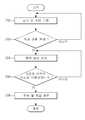
도 5는 본 발명의 실시예에 의한 역 구동성이 높은 로봇 팔을 안전하게 정지시키는 방법을 설명하기 위한 동작 순서도이다.FIG. 5 is a flow chart illustrating a method for safely stopping a robotic arm having high reversibility in accordance with an embodiment of the present invention. Referring to FIG.
도 5에서, 역 구동성이 높은 로봇 팔(130R, 130L)은 인간과 상호 작용하는 작업(예를 들어, 인간과 포옹하는 것 등)을 수행하기 위하여 작업에 필요한 토크를 계산하여 관절((132R, 132L), (133R, 133L), (134R, 134L))의 모터(158)에 출력함으로서 로봇 팔(130R, 130L)을 움직이는 작업을 수행한다(200). 이러한 작업 제어 시 중력 보상 제어 부분은 필요에 따라 계산될 수도 있고 사용하지 않을 수도 있다.5,
이와 같이, 역 구동성이 높은 로봇 팔(130R, 130L)의 작업을 수행하는 중에 로봇 팔(130R, 130L)의 작업을 정지해야 하는 비상 상황이 발생하였는지를 판단한다(202).In this way, it is determined whether there is an emergency situation in which the operation of the
비상 상황의 발생 여부를 판단하는 것은, 로봇 팔(130R, 130L)의 각 관절((132R, 132L), (133R, 133L), (134R, 134L))에 마련된 모터(158)에 흐르는 전류를 안전모드 감지부(150)의 전류센서(151)를 통해 측정하거나 또는 로봇 팔(130R, 130L)의 각 관절((132R, 132L), (133R, 133L), (134R, 134L))의 속도를 안전모드 감지부(150)의 엔코더(152)를 통해 감지한다.Determining whether or not an emergency situation has occurred is to determine the current flowing through the
따라서, 제어부(154)는 전류센서(151)에 의해 측정된 전류를 미리 정해진 제어 기준 값과 비교하여 과도한 토크의 발생 여부를 체크하거나 또는 엔코더(152)에 의해 감지된 속도를 미리 정해진 제어 기준 값과 비교하여 비정상적인 속도의 발생 여부를 체크하여 로봇 팔(130R, 130L)이 작업을 정지해야 하는 비상 상황이 발생하였는지를 판단하는 것이다.Therefore, the
한편, 본 발명의 실시예에서는 전류센서(151) 또는 엔코더(152)를 통해 토크나 속도를 체크하여 로봇 팔(130R, 130L)의 작업을 정지해야 하는 비상 상황이 발생하였는지를 판단하는 것을 예로 들어 설명하였으나, 본 발명은 이에 한정되지 않고 엔코더(152)를 통해 감지한 로봇 팔(130R, 130L)의 각 관절((132R, 132L), (133R, 133L), (134R, 134L))의 속도에 따른 가속도 값을 가지고 비상 상황의 발생 여부를 판단할 수 있으며, 또한 로봇(100)의 넘어짐이나 기타 여러 가지 원인에 의한 돌발 상황 시에도 비상 상황이라고 판단할 수 있다.Meanwhile, in the embodiment of the present invention, it is exemplified that an emergency situation in which the operation of the
단계 202의 판단 결과, 비상 상황이 발생한 경우 제어부(154)는 로봇 팔(130R, 130L)이 수행하던 작업을 중지하고 로봇 팔(130R, 130L)을 안전하게 정지시키도록 중력 보상 제어를 수행한다(204).If it is determined in
중력 보상 제어는 로봇 팔(130R, 130L)에 작용하는 중력을 보상할 정도의 토크 즉, 로봇 팔(130R, 130L)이 중력에 의해 낙하하지 않고 현재 상태의 기구학적 위치를 유지할 수 있을 정도의 토크만 출력하여 로봇 팔(130R, 130L)이 마치 무중력 상태에 있는 것처럼 제어하는 것으로, 중력 보상 제어를 수행하게 되면 사용자가 로봇 팔(130R, 130L)에 가까이 있거나 끼어 있는 경우에도 사용자가 로봇 팔(130R, 130L)을 쉽게 움직일 수 있기 때문에 로봇 팔(130R, 130L)에서 안전하게 벗어날 수 있으며, 또한 로봇 팔(130R, 130L)의 중력으로 인한 낙하를 방지하여 로봇 팔(130R, 130L)이 주변 환경과 충돌하는 것을 방지할 수 있기 때문에 로봇 팔(130R, 130L)의 기구장치나 주변 환경은 물론 사용자 안전까지도 보호할 수 있게 된다.The gravity compensation control is performed by a torque enough to compensate for the gravity acting on the
중력 보상 제어를 위한 토크 계산방법을 도 4를 참조하여 설명한다.A torque calculation method for gravity compensation control will be described with reference to Fig.
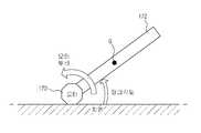
도 4는 본 발명의 실시예에 의한 중력 보상 제어의 토크를 계산하는 방법을 예시한 도면이다.4 is a diagram illustrating a method of calculating a torque of gravity compensation control according to an embodiment of the present invention.
도 4에서, 모터(170)는 지면에 설치되어 있고, 모터(170)의 구동축에 링크(172)가 연결되어 있으며, 링크(172)는 질량을 가지고 있어 중력으로 인해 질량에 중력가속도를 곱한 크기 만큼의 무게가 중력 방향으로 작용하게 된다.4, the
중력 보상 제어는 이러한 상황에서 외력이 가해지지 않을 때 링크(172)가 움직이지 않도록 하는 최소한의 토크를 모터(170)에서 발생하는 것으로, 토크는 링크(172)의 무게를 대표하는 무게 중심(G)과 링크(172)의 무게, 링크(172)와 지면이 이루는 링크 각도를 이용하여 계산한다. 링크 각도가 작을수록 링크(172)가 움직이지 않도록 하기 위하여 큰 토크를 발생하게 되며, 링크 각도가 지면과 수직한 경우 토크는 0에 가깝게 된다.The gravity compensation control is such that a minimum torque is generated in the
이와 같이, 외력에 의해 링크(172)가 움직이게 되는 경우 바뀌는 링크 각도에 따라 토크를 계산하는데 아래의 식 [1]와 같이, 링크 각도 즉, 관절각(θ)의 함수로 나타낼 수 있다.In this way, when the
τ=g(θ)...... 식 [1]? = g (?) Equation [1]
여기서,τ는 모터(170) 토크를 나타내고,g는 링크 각도(θ)에 따른 중력 보상 함수의 맵핑을 나타낸다.Where,τ represents a
이후, 제어부(154)는 로봇 팔(130R, 130L)의 중력 보상 제어를 통해 사용자가 로봇 팔(130R, 130L)에서 안전한 위치로 이동하였는지를 모니터링하는데(206), 사용자가 안전한 위치로 이동하였는지를 모니터링하는 방법은 사용자가 안전한 위치로 이동한 후에 입력부(160)를 통해 로봇 팔(130R, 130L)의 작업을 안전하게 종료하기 위한 명령을 직접 입력하거나 사용자가 안전한 위치(예를 들어, 로봇 팔을 초기 위치로 이동시킨 경우)로 이동하였는지를 로봇(100)에 설치된 각종 센서(3차원 측정장비, F/T센서 등)를 통해 모니터링할 수 있다.The
사용자가 안전한 위치로 이동하였다고 판단되면, 제어부(154)는 전원제어신호를 전원차단부(162)에 전달하고, 전원차단부(162)는 제어부(154)의 전원제어신호에 따라 로봇 팔(130R, 130L)에 공급되는 전원을 차단시키거나 대기모드로 전환시켜 로봇 팔(130R, 130L)의 작업을 종료한다(208).If the user determines that the user has moved to a safe position, the
도 1은 본 발명의 실시예에 의한 로봇의 개략적인 구성을 나타내는 사시도이다.1 is a perspective view showing a schematic configuration of a robot according to an embodiment of the present invention.
도 2는 도 1에 나타낸 로봇의 주요 관절 구조를 나타낸 도면이다.Fig. 2 is a view showing a main joint structure of the robot shown in Fig. 1. Fig.
도 3은 본 발명의 실시예에 의한 역 구동성이 높은 로봇 팔을 안전하게 정지시키기 위한 제어 블록도이다.FIG. 3 is a control block diagram for safely stopping a robotic arm having high reversibility in accordance with an embodiment of the present invention.
도 4는 본 발명의 실시예에 의한 중력 보상 제어의 토크를 계산하는 방법을 예시한 도면이다.4 is a diagram illustrating a method of calculating a torque of gravity compensation control according to an embodiment of the present invention.
도 5는 본 발명의 실시예에 의한 역 구동성이 높은 로봇 팔을 안전하게 정지시키는 방법을 설명하기 위한 동작 순서도이다.FIG. 5 is a flow chart illustrating a method for safely stopping a robotic arm having high reversibility in accordance with an embodiment of the present invention. Referring to FIG.
*도면의 주요 부분에 대한 부호의 설명*Description of the Related Art [0002]
100 : 로봇130R, 130L : 로봇 팔100:
132R, 132L : 어깨 관절133R, 133L : 팔꿈치 관절132R, 132L:
134R, 134L : 손목 관절150 : 안전모드 감지부134R, 134L: wrist joint 150: safety mode detection unit
151 : 전류센서152 : 엔코더151: current sensor 152: encoder
154 : 제어부156 : 구동부154: control unit 156:
158 : 모터160 : 입력부158: motor 160: input part
162 : 전원차단부162:
Claims (17)
Translated fromKoreanPriority Applications (2)
| Application Number | Priority Date | Filing Date | Title |
|---|---|---|---|
| KR1020080123182AKR101474765B1 (en) | 2008-12-05 | 2008-12-05 | Robot arm and control method thereof |
| US12/588,691US8405340B2 (en) | 2008-12-05 | 2009-10-23 | Robot arm and method of controlling the same |
Applications Claiming Priority (1)
| Application Number | Priority Date | Filing Date | Title |
|---|---|---|---|
| KR1020080123182AKR101474765B1 (en) | 2008-12-05 | 2008-12-05 | Robot arm and control method thereof |
Publications (2)
| Publication Number | Publication Date |
|---|---|
| KR20100064654A KR20100064654A (en) | 2010-06-15 |
| KR101474765B1true KR101474765B1 (en) | 2014-12-22 |
Family
ID=42230335
Family Applications (1)
| Application Number | Title | Priority Date | Filing Date |
|---|---|---|---|
| KR1020080123182AActiveKR101474765B1 (en) | 2008-12-05 | 2008-12-05 | Robot arm and control method thereof |
Country Status (2)
| Country | Link |
|---|---|
| US (1) | US8405340B2 (en) |
| KR (1) | KR101474765B1 (en) |
Families Citing this family (21)
| Publication number | Priority date | Publication date | Assignee | Title |
|---|---|---|---|---|
| KR20120071599A (en)* | 2010-12-23 | 2012-07-03 | 삼성전자주식회사 | Walking robot and control method thereof |
| US9119655B2 (en) | 2012-08-03 | 2015-09-01 | Stryker Corporation | Surgical manipulator capable of controlling a surgical instrument in multiple modes |
| US9815193B2 (en) | 2011-06-27 | 2017-11-14 | Delaware Capital Formation, Inc. | Electric motor based holding control systems and methods |
| KR101284987B1 (en) | 2011-09-09 | 2013-07-10 | 고려대학교 산학협력단 | Torque-free robot arm using multi-DOF counterbalance mechanism based on double parallelogram mechanism |
| US9183346B2 (en)* | 2012-03-12 | 2015-11-10 | Empire Technology Development Llc | Robotic appendages |
| CN107198567B (en) | 2012-08-03 | 2021-02-09 | 史赛克公司 | Systems and methods for robotic surgery |
| US9226796B2 (en) | 2012-08-03 | 2016-01-05 | Stryker Corporation | Method for detecting a disturbance as an energy applicator of a surgical instrument traverses a cutting path |
| KR102150633B1 (en)* | 2013-09-13 | 2020-09-01 | (주)미래컴퍼니 | Structure and design method of control arm |
| KR20150047076A (en) | 2013-10-22 | 2015-05-04 | 고려대학교 산학협력단 | Torque-free linkage unit |
| US10471610B2 (en) | 2015-06-16 | 2019-11-12 | Samsung Electronics Co., Ltd. | Robot arm having weight compensation mechanism |
| CN108430375B (en) | 2015-11-11 | 2021-05-07 | 马科外科公司 | Robotic system and method of back-driving the same |
| US11202682B2 (en) | 2016-12-16 | 2021-12-21 | Mako Surgical Corp. | Techniques for modifying tool operation in a surgical robotic system based on comparing actual and commanded states of the tool relative to a surgical site |
| EP3418007A1 (en)* | 2017-06-19 | 2018-12-26 | ABB Schweiz AG | Method of determining a joint torque in a joint of an articulated industrial robot |
| WO2019190487A1 (en)* | 2018-03-27 | 2019-10-03 | Productive Robotics, Inc. | Collaborative robot system incorporating enhanced human interface |
| US20200039064A1 (en)* | 2018-08-06 | 2020-02-06 | The Regents Of The University Of California | Low-Cost Compliant Robot Arm and System for Manipulation |
| CN109531565B (en)* | 2018-08-27 | 2023-11-03 | 苏州博众智能机器人有限公司 | Control method and device of mechanical arm, service robot and storage medium |
| CN111061215B (en)* | 2019-12-26 | 2021-01-22 | 北京市商汤科技开发有限公司 | Method and device for controlling robot to get rid of poverty and robot |
| CN112025698B (en)* | 2020-07-13 | 2021-11-23 | 北京大学 | Robot falling protection method and system based on impact prediction and active compliance |
| JP7724086B2 (en)* | 2021-06-16 | 2025-08-15 | 株式会社日立製作所 | Equipment diagnosis device and equipment diagnosis method |
| US11865695B2 (en)* | 2021-11-16 | 2024-01-09 | Walton Richardson | Humanoid hugging assembly |
| CN115901290B (en)* | 2022-11-03 | 2025-06-24 | 东风商用车有限公司 | L3 level autopilot test system |
Citations (3)
| Publication number | Priority date | Publication date | Assignee | Title |
|---|---|---|---|---|
| JP2006252383A (en)* | 2005-03-14 | 2006-09-21 | Seiko Epson Corp | Acceleration / deceleration control method and apparatus, and acceleration / deceleration control method program |
| JP2007301680A (en)* | 2006-05-11 | 2007-11-22 | Nachi Fujikoshi Corp | Robot arm diagnosis device |
| JP4054984B2 (en)* | 2001-12-20 | 2008-03-05 | 株式会社安川電機 | Robot control apparatus and control method |
Family Cites Families (11)
| Publication number | Priority date | Publication date | Assignee | Title |
|---|---|---|---|---|
| US7345672B2 (en)* | 1992-12-02 | 2008-03-18 | Immersion Corporation | Force feedback system and actuator power management |
| JP3114579B2 (en)* | 1995-08-30 | 2000-12-04 | 松下電器産業株式会社 | Industrial robot and its control device |
| WO1997010081A1 (en)* | 1995-09-11 | 1997-03-20 | Kabushiki Kaisha Yaskawa Denki | Robot controller |
| JPH09254079A (en)* | 1996-03-22 | 1997-09-30 | Yaskawa Electric Corp | Robot control device |
| JP3288250B2 (en)* | 1997-03-25 | 2002-06-04 | ファナック株式会社 | Robot controller |
| US7768549B2 (en)* | 2001-06-08 | 2010-08-03 | Honeywell International Inc. | Machine safety system with mutual exclusion zone |
| JP4472592B2 (en)* | 2004-08-30 | 2010-06-02 | 本田技研工業株式会社 | Control method, control system, and control program for moving body |
| DE102004042489B4 (en)* | 2004-08-31 | 2012-03-29 | Siemens Ag | Medical examination or treatment facility with associated method |
| JP2007286904A (en)* | 2006-04-17 | 2007-11-01 | Fanuc Ltd | Controller and control method for motor |
| WO2007136769A2 (en)* | 2006-05-19 | 2007-11-29 | Mako Surgical Corp. | Method and apparatus for controlling a haptic device |
| JP4335286B2 (en)* | 2008-02-08 | 2009-09-30 | ファナック株式会社 | Robot control apparatus and robot control method having component protection function |
- 2008
- 2008-12-05KRKR1020080123182Apatent/KR101474765B1/enactiveActive
- 2009
- 2009-10-23USUS12/588,691patent/US8405340B2/enactiveActive
Patent Citations (3)
| Publication number | Priority date | Publication date | Assignee | Title |
|---|---|---|---|---|
| JP4054984B2 (en)* | 2001-12-20 | 2008-03-05 | 株式会社安川電機 | Robot control apparatus and control method |
| JP2006252383A (en)* | 2005-03-14 | 2006-09-21 | Seiko Epson Corp | Acceleration / deceleration control method and apparatus, and acceleration / deceleration control method program |
| JP2007301680A (en)* | 2006-05-11 | 2007-11-22 | Nachi Fujikoshi Corp | Robot arm diagnosis device |
Also Published As
| Publication number | Publication date |
|---|---|
| KR20100064654A (en) | 2010-06-15 |
| US8405340B2 (en) | 2013-03-26 |
| US20100141197A1 (en) | 2010-06-10 |
Similar Documents
| Publication | Publication Date | Title |
|---|---|---|
| KR101474765B1 (en) | Robot arm and control method thereof | |
| De Luca et al. | Collision detection and safe reaction with the DLR-III lightweight manipulator arm | |
| US8483877B2 (en) | Workspace safe operation of a force- or impedance-controlled robot | |
| JP6924146B2 (en) | Robot system monitoring device | |
| Yu et al. | Development of a upper-limb exoskeleton robot for refractory construction | |
| Gosselin et al. | A friendly beast of burden: A human-assistive robot for handling large payloads | |
| JP5191738B2 (en) | Manipulator control method and control system | |
| US20100234996A1 (en) | Manipulator, Particularly Industrial Robot, Having A Redundant Sensor Arrangement, And Method For The Control Thereof | |
| US20200269423A1 (en) | Device and method for controlling cooperative robot | |
| JP2017507041A (en) | Industrial robot safety system | |
| JP5367049B2 (en) | System and method for applying tension to a robot-driven tendon | |
| US20120133318A1 (en) | Control apparatus, control method, and control program for elastic actuator drive mechanism | |
| JP2016028842A (en) | Actuator system | |
| JP6417034B2 (en) | Cobotic manipulator | |
| KR20110016315A (en) | Emergency stop system of multi-axis robot | |
| KR20220145387A (en) | robot device | |
| Shut et al. | Development of a humanoid dual arm system for a single spherical wheeled balancing mobile robot | |
| Borghesan et al. | Constraint-based specification of hybrid position-impedance-force tasks | |
| TWI753287B (en) | Robot control device | |
| Yanai et al. | Anti-sway control for wire-suspended mechanism based on dynamics compensation | |
| Badger et al. | Model-based robotic dynamic motion control for the Robonaut 2 humanoid robot | |
| KR20230054471A (en) | Current limiting device, robotic system and current limiting method | |
| Benallegue et al. | On compliance and safety with torque-control for robots with high reduction gears and no joint-torque feedback | |
| Lu et al. | Collision detection enabled weighted path planning: a wrist and base force/torque sensors approach | |
| KR102855324B1 (en) | Robot control system and method |
Legal Events
| Date | Code | Title | Description |
|---|---|---|---|
| PA0109 | Patent application | Patent event code:PA01091R01D Comment text:Patent Application Patent event date:20081205 | |
| PG1501 | Laying open of application | ||
| A201 | Request for examination | ||
| PA0201 | Request for examination | Patent event code:PA02012R01D Patent event date:20131203 Comment text:Request for Examination of Application Patent event code:PA02011R01I Patent event date:20081205 Comment text:Patent Application | |
| E902 | Notification of reason for refusal | ||
| PE0902 | Notice of grounds for rejection | Comment text:Notification of reason for refusal Patent event date:20140924 Patent event code:PE09021S01D | |
| E701 | Decision to grant or registration of patent right | ||
| PE0701 | Decision of registration | Patent event code:PE07011S01D Comment text:Decision to Grant Registration Patent event date:20141128 | |
| GRNT | Written decision to grant | ||
| PR0701 | Registration of establishment | Comment text:Registration of Establishment Patent event date:20141215 Patent event code:PR07011E01D | |
| PR1002 | Payment of registration fee | Payment date:20141216 End annual number:3 Start annual number:1 | |
| PG1601 | Publication of registration | ||
| FPAY | Annual fee payment | Payment date:20171120 Year of fee payment:4 | |
| PR1001 | Payment of annual fee | Payment date:20171120 Start annual number:4 End annual number:4 | |
| FPAY | Annual fee payment | Payment date:20181119 Year of fee payment:5 | |
| PR1001 | Payment of annual fee | Payment date:20181119 Start annual number:5 End annual number:5 | |
| PR1001 | Payment of annual fee | Payment date:20201119 Start annual number:7 End annual number:7 | |
| PR1001 | Payment of annual fee | Payment date:20211115 Start annual number:8 End annual number:8 | |
| PR1001 | Payment of annual fee | Payment date:20221114 Start annual number:9 End annual number:9 | |
| PR1001 | Payment of annual fee | Payment date:20241114 Start annual number:11 End annual number:11 |