KR101472128B1 - Shadow mask frame and apparatus for fabricating organic electro-luminescence display device using the same - Google Patents
Shadow mask frame and apparatus for fabricating organic electro-luminescence display device using the sameDownload PDFInfo
- Publication number
- KR101472128B1 KR101472128B1KR1020070136146AKR20070136146AKR101472128B1KR 101472128 B1KR101472128 B1KR 101472128B1KR 1020070136146 AKR1020070136146 AKR 1020070136146AKR 20070136146 AKR20070136146 AKR 20070136146AKR 101472128 B1KR101472128 B1KR 101472128B1
- Authority
- KR
- South Korea
- Prior art keywords
- shadow mask
- edge
- fixed
- base frame
- frame
- Prior art date
- Legal status (The legal status is an assumption and is not a legal conclusion. Google has not performed a legal analysis and makes no representation as to the accuracy of the status listed.)
- Active
Links
Images


Classifications
- H—ELECTRICITY
- H05—ELECTRIC TECHNIQUES NOT OTHERWISE PROVIDED FOR
- H05B—ELECTRIC HEATING; ELECTRIC LIGHT SOURCES NOT OTHERWISE PROVIDED FOR; CIRCUIT ARRANGEMENTS FOR ELECTRIC LIGHT SOURCES, IN GENERAL
- H05B33/00—Electroluminescent light sources
- H05B33/10—Apparatus or processes specially adapted to the manufacture of electroluminescent light sources
- C—CHEMISTRY; METALLURGY
- C23—COATING METALLIC MATERIAL; COATING MATERIAL WITH METALLIC MATERIAL; CHEMICAL SURFACE TREATMENT; DIFFUSION TREATMENT OF METALLIC MATERIAL; COATING BY VACUUM EVAPORATION, BY SPUTTERING, BY ION IMPLANTATION OR BY CHEMICAL VAPOUR DEPOSITION, IN GENERAL; INHIBITING CORROSION OF METALLIC MATERIAL OR INCRUSTATION IN GENERAL
- C23C—COATING METALLIC MATERIAL; COATING MATERIAL WITH METALLIC MATERIAL; SURFACE TREATMENT OF METALLIC MATERIAL BY DIFFUSION INTO THE SURFACE, BY CHEMICAL CONVERSION OR SUBSTITUTION; COATING BY VACUUM EVAPORATION, BY SPUTTERING, BY ION IMPLANTATION OR BY CHEMICAL VAPOUR DEPOSITION, IN GENERAL
- C23C14/00—Coating by vacuum evaporation, by sputtering or by ion implantation of the coating forming material
- C23C14/04—Coating on selected surface areas, e.g. using masks
- C23C14/042—Coating on selected surface areas, e.g. using masks using masks
- C—CHEMISTRY; METALLURGY
- C23—COATING METALLIC MATERIAL; COATING MATERIAL WITH METALLIC MATERIAL; CHEMICAL SURFACE TREATMENT; DIFFUSION TREATMENT OF METALLIC MATERIAL; COATING BY VACUUM EVAPORATION, BY SPUTTERING, BY ION IMPLANTATION OR BY CHEMICAL VAPOUR DEPOSITION, IN GENERAL; INHIBITING CORROSION OF METALLIC MATERIAL OR INCRUSTATION IN GENERAL
- C23C—COATING METALLIC MATERIAL; COATING MATERIAL WITH METALLIC MATERIAL; SURFACE TREATMENT OF METALLIC MATERIAL BY DIFFUSION INTO THE SURFACE, BY CHEMICAL CONVERSION OR SUBSTITUTION; COATING BY VACUUM EVAPORATION, BY SPUTTERING, BY ION IMPLANTATION OR BY CHEMICAL VAPOUR DEPOSITION, IN GENERAL
- C23C14/00—Coating by vacuum evaporation, by sputtering or by ion implantation of the coating forming material
- C23C14/06—Coating by vacuum evaporation, by sputtering or by ion implantation of the coating forming material characterised by the coating material
- C23C14/12—Organic material
- H—ELECTRICITY
- H10—SEMICONDUCTOR DEVICES; ELECTRIC SOLID-STATE DEVICES NOT OTHERWISE PROVIDED FOR
- H10K—ORGANIC ELECTRIC SOLID-STATE DEVICES
- H10K71/00—Manufacture or treatment specially adapted for the organic devices covered by this subclass
Landscapes
- Chemical & Material Sciences (AREA)
- Engineering & Computer Science (AREA)
- Manufacturing & Machinery (AREA)
- Chemical Kinetics & Catalysis (AREA)
- Materials Engineering (AREA)
- Mechanical Engineering (AREA)
- Metallurgy (AREA)
- Organic Chemistry (AREA)
- Electroluminescent Light Sources (AREA)
Abstract
Translated fromKoreanDescription
Translated fromKorean본 발명은 새도우마스크 프레임에 관한 것으로, 특히 효율을 향상시키고, 비용을 줄일 수 있는 새도우마스크 프레임 및 이를 이용한 유기전계발광 표시장치의 제조장치에 관한 것이다.The present invention relates to a shadow mask frame, and more particularly, to a shadow mask frame capable of improving efficiency and reducing cost and an apparatus for manufacturing an organic light emitting display using the shadow mask frame.
최근, 음극선관(Cathode Ray Tube)의 단점인 무게와 부피를 줄일 수 있는 각종 평판 표시장치들이 대두되고 있다. 이러한 평판 표시장치로는 크게 액정표시장치(Liquid Crystal Display), 전계방출 표시장치(Field Emission Display), 플라즈마 표시장치(Plasma Display Panel) 및 유기전계발광 표시장치(Organic electro luminescence Display device) 등이 있다.2. Description of the Related Art In recent years, various flat panel display devices that can reduce weight and volume, which are disadvantages of cathode ray tubes (CRTs), are emerging. Such flat panel display devices include a liquid crystal display, a field emission display, a plasma display panel, and an organic electro luminescence display device .
이들 중 유기전계발광 표시장치는 전자와 정공의 재결합으로 발광물질을 발광시키는 자발광소자이다.Among these organic electroluminescent display devices are self-luminous devices that emit light-emitting materials by recombination of electrons and holes.
상기 유기전계발광 표시장치는 액정표시장치와 같이 별도의 광원을 필요로 하는 수동형 발광소자에 비하여 응답속도가 음극선관과 같은 수준으로 빠르다는 장 점을 가지고 있다. 또한, 상기 유기전계발광 표시장치는 저전압 구동, 자기발광, 박막형, 넓은 시야각, 빠른 응답속도 및 높은 콘트라스트 등의 많은 장점을 가지고 있어 차세대 표시장치로 기대되고 있다.The organic light emitting display device has the advantage that the response speed is faster than that of a passive light emitting device requiring a separate light source such as a liquid crystal display device. Further, the organic light emitting display device has many advantages such as low voltage driving, self light emission, thin film type, wide viewing angle, fast response speed and high contrast, and is expected as a next generation display device.
상기 유기전계발광 표시장치는 다수의 서브픽셀이 매트릭스 형태로 배열된다. 각 서브픽셀에는 박막 트랜지스터와 유기발광 다이오드소자가 형성된다. 유기발광 다이오드소자는 제1 전극, 유기 발광층 및 제2 전극으로 이루어질 수 있다. 상기 유기 발광층은 정공주입층, 정공수송층, 발광층, 전자수송층 및 전자주입층을 포함할 수 있다.In the organic light emitting display, a plurality of sub-pixels are arranged in a matrix form. In each sub-pixel, a thin film transistor and an organic light emitting diode element are formed. The organic light emitting diode device may include a first electrode, an organic light emitting layer, and a second electrode. The organic light emitting layer may include a hole injecting layer, a hole transporting layer, a light emitting layer, an electron transporting layer, and an electron injecting layer.
상기 유기 발광층은 서브픽셀마다 형성되어야 하는데, 이를 위해 새도우마스크가 사용된다. 즉, 새도우마스크를 기판 상에 정렬한 후, 증착 장비를 이용하여 유기물을 방출시키면, 유기물이 새도우마스크를 부분적으로 투과하여 원하는 위치에 발광층이 형성된다.The organic light emitting layer must be formed for each sub-pixel, and a shadow mask is used for this purpose. That is, when the shadow mask is aligned on a substrate and organic materials are discharged using a deposition apparatus, the organic material partially penetrates the shadow mask to form a light emitting layer at a desired position.
상기 새도우마스크는 서로 이격된 다수의 패턴들로 이루어진다.The shadow mask is composed of a plurality of patterns spaced apart from each other.
상기 새도우마스크를 지지하기 위해 지지 사각 틀의 새도우마스크 프레임이 구비된다. 상기 새도우마스크 프레임은 메탈 재질로서, 상기 새도우마스크의 평탄도를 유지시킴과 아울러 새도우마스크의 유동을 방지하는 역할을 한다.A shadow mask frame of a supporting square frame is provided to support the shadow mask. The shadow mask frame is made of a metal material and serves to maintain the flatness of the shadow mask and to prevent the shadow mask from flowing.
그러나, 종래의 새도우마스크 프레임은 새도우마스크와의 고정(일반적으로 웰딩(Welding)공정을 통해 고정됨) 과정에서 뒤틀림이 발생하여 기판과 새도우마스크의 평탄도를 유지하기 어려운 문제가 있었다.However, the conventional shadow mask frame has a problem in that it is difficult to maintain the flatness of the substrate and the shadow mask due to the warping in the process of fixing the shadow mask with the shadow mask (generally fixed through a welding process).
특히, 새도우마스크 프레임의 국부적인 뒤틀립은 새도우마스크 뿐만 아니라 새도우마스크 프레임도 폐기처리되어 고가의 비용 손실을 발생한다.Particularly, the local twist of the shadow mask frame discards not only the shadow mask but also the shadow mask frame, resulting in costly cost loss.
본 발명은 새도우마스크 프레임의 효율을 향상시킬 수 있는 새도우마스크 프레임을 제공함에 그 목적이 있다.An object of the present invention is to provide a shadow mask frame capable of improving the efficiency of a shadow mask frame.
또한, 본 발명은 새로운 구조의 새도우마스크 프레임을 적용하여 비용을 줄일 수 있는 유기전계발광 표시장치의 제조장치를 제공함에 그 목적이 있다.It is another object of the present invention to provide an apparatus for manufacturing an organic light emitting display device which can reduce the cost by applying a shadow mask frame having a novel structure.
본 발명의 일 실시예에 따른 새도우마스크 프레임은,According to an aspect of the present invention, there is provided a shadow mask frame,
사각 틀 형상으로 이루어진 베이스 프레임; 및 상기 베이스 프레임의 가장자리 상에 배치되어 새도우마스크가 고정되는 복수의 지지부를 포함하는 것을 특징으로 한다.A base frame having a square frame shape; And a plurality of supports arranged on an edge of the base frame and to which the shadow mask is fixed.
또한, 본 발명의 일 실시예에 따른 유기전계발광 표시장치의 제조장치는,According to another aspect of the present invention, there is provided an apparatus for fabricating an organic light emitting display,
일정한 간격을 두고 슬릿이 형성되어 기판상에 발광물질을 선택적으로 형성시키기 위한 새도우마스크; 및 사각 틀 형상으로 이루어진 베이스 프레임과 상기 베이스 프레임의 가장자리 상에 배치되어 새도우마스크가 고정되는 복수의 지지부를 포함하는 새도우마스크 프레임;을 포함하는 것을 특징으로 한다.A shadow mask for selectively forming a light emitting material on a substrate by forming a slit at regular intervals; And a shadow mask frame including a base frame having a rectangular frame shape and a plurality of supports arranged on an edge of the base frame to fix the shadow mask.
본 발명은 새도우마스크와 직접 웰딩(Welding)되는 복수의 고정 지지바 및 에지 지지바가 베이스 프레임 상에 배치되어, 웰딩 과정에서 휘어짐 특히, 국부적인 휘어짐 발생 시에 휘어진 고정 지지바 또는 에지 지지바를 교체함으로써, 새도 우마스크 프레임의 효율을 향상시킬 수 있다.The present invention is characterized in that a plurality of stationary support bars and edge support bars which are directly welded to the shadow mask are disposed on the base frame to replace the curved stationary support bars or edge support bars in the course of warping, , The efficiency of the new mask frame can be improved.
따라서, 본 발명은 새도우 마스크 프레임의 효율을 높일 수 있는 구조를 적용하여 종래와 대비하여 비용을 줄일 수 있는 효과가 있다.Therefore, the present invention can reduce the cost compared with the conventional art by applying a structure that can increase the efficiency of the shadow mask frame.
첨부한 도면을 참조하여 본 발명에 따른 실시 예를 상세히 설명하도록 한다.DETAILED DESCRIPTION OF THE PREFERRED EMBODIMENTS Referring to the accompanying drawings, embodiments of the present invention will be described in detail.
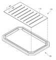
도 1은 본 발명의 일 실시예에 따른 새도우마스크 및 새도우마스크 프레임을 도시한 분해사시도이고, 도 2는 새도우마스크 프레임을 도시한 분해사시도이고, 도 3은 도 1의 Ⅰ-Ⅰ' 라인을 따라 절단한 새도우마스크 프레임의 단면도이다.FIG. 1 is an exploded perspective view showing a shadow mask and a shadow mask frame according to an embodiment of the present invention, FIG. 2 is an exploded perspective view showing a shadow mask frame, and FIG. 3 is a cross-sectional view taken along line I- Sectional view of the cut shadow mask frame.
도 1 내지 도 3에 도시된 바와 같이, 본 발명의 일 실시예에 따른 새도우마스크(100)는 새도우마스크 프레임(130) 상에 고정된다.1 to 3, the
새도우마스크(100)는 관통되어 오픈된 영역, 즉 다수의 슬릿(110)이 형성된다. 상기 슬릿(110)은 새도우마스크(100)의 하부에서 상부로 또는 상부에서 하부로 증착하고 하는 물질이 통과될 수 있다.The
새도우마스크 프레임(130)은 사각 틀 형태의 베이스 프레임(131)과, 상기 베이스 프레임(131)의 가장자리를 따라 배치된 복수의 고정 지지부(135a, 135b, 135c, 135d)와, 상기 베이스 프레임(131)의 모서리 영역에 배치되는 복수의 에지 지지부(137a, 137b, 137c, 137d)를 포함한다.The
상기 베이스 프레임(131), 고정 지지부(135a 내지 135d) 및 에지 지지부(137a 내지 137d)는 메탈재질로 이루어진다.The
베이스 프레임(131)은 내측면에 상기 고정 지지부(135a 내지 135d) 및 에지 지지부(137a 내지 137d)를 가이드하는 가이드 돌기(133)가 구비된다.The
가이드 돌기(133)는 상기 고정 지지부(135a 내지 135d) 및 에지 지지부(137a 내지 137d)가 베이스 프레임(131)의 내측 방향으로 유동하지 못하게 가이드하는 역할을 한다.The
가이드 돌기(133)는 베이스 프레임(131)의 내측면으로부터 상부방향으로 구부러진 구조로써, 상기 베이스 프레임(131)과 일체로 이루어진다.The
본 발명의 일 실시예에서는 가이드 돌기(133)가 상기 베이스 프레임(131)의 모서리 영역에서 서로 끊어진 구조로 이루어지지만, 이에 한정하지 않고, 모두 연결된 구조로 이루어질 수도 있다.In one embodiment of the present invention, the
고정 지지부(135a 내지 135d)는 상기 베이스 프레임(131)의 가장자리 상부면과 접촉되며, 상기 가이드 돌기(133)의 외측면과 접촉된다.The fixed supports 135a to 135d contact the upper surface of the edge of the
고정 지지부(135a 내지 135d)는 바타입으로 이루어지고, 상기 가이드 돌기(133)와 동일한 높이로 이루어진다.The
도면에는 도시되지 않았지만, 고정 지지부(135a 내지 135d)는 스크류 방식으로 상기 베이스 프레임(131) 상에 고정되며, 상기 스크류(미도시)는 상기 베이스 프레임(131)의 하부면으로부터 상기 베이스 프레임(131)을 관통하여 상기 고정 지지부(135a 내지 135d)를 고정한다.Although not shown in the drawing, the
에지 지지부(137a 내지 137d)는 상기 베이스 프레임(131)의 모서리 상부면 상에 배치되며, 상기 고정 지지부(135a 내지 135d)의 양끝단과 접촉된다.The
즉, 에지 지지부(137a 내지 137d)는 상기 고정 지지부(135a 내지 135d)의 양 끝단과 접촉될 수 있도록 구부러진 구조로 이루어진다.That is, the
에지 지지부(137a 내지 137d)의 양측면에는 상기 고정 지지부(135a 내지 135d)의 측면과 접촉될 뿐만 아니라 상기 가이드 돌기(133)와 접촉되도록 단차를 가진다.The both side surfaces of the
도면에는 도시되지 않았지만, 에지 지지부(137a 내지 137d)는 스크류 방식으로 상기 베이스 프레임(131) 상에 고정되며, 상기 스크류(미도시)는 상기 베이스 프레임(131)의 하부면으로부터 상기 베이스 프레임(131)을 관통하여 상기 에지 지지부(137a 내지 137d)를 고정한다.Although not shown in the drawing, the edge supports 137a to 137d are fixed on the
에지 지지부(137a 내지 137d)와 상기 고정 지지부(135a 내지 135d)는 상기 새도우마스크(100) 고정시 평탄도를 유지할 수 있도록 동일한 높이로 이루어진다.The
베이스 프레임(131) 상에 고정 지지부(135a 내지 135d) 및 에지 지지부(137a 내지 137d)가 고정되면, 상기 새도우마스크(100)는 고정 지지부(135a 내지 135d) 및 에지 지지부(137a 내지 137d) 상에 안착되고, 웰딩 방법으로 상기 고정 지지부(135a 내지 135d) 및 에지 지지부(137a 내지 137d) 상에 고정된다.When the fixed supports 135a to 135d and the
본 발명은 새도우마스크(100)의 교체 시에 상기 새도우마스크(100)를 제거하고, 고정 지지부(135a 내지 135d) 및 에지 지지부(137a 내지 137d)의 상부면을 연마하여 새로운 새도우마스크(100)를 웰딩하여 사용한다. 여기서, 가이드 돌기(133)는 상기 고정 지지부(135a 내지 135d) 및 에지 지지부(137a 내지 137d)의 연마 공정 시에 동시에 연마될 수 있다.The present invention is characterized in that when replacing the
이상에서 설명한 바와 같이, 본 발명의 일 실시예에 따른 새도우마스크 프레 임(130)은 새도우마스크(100)와 직접 웰딩되는 복수의 고정 지지바(135a 내지 135d) 및 에지 지지바(137a 내지 137d)가 구비됨으로써, 웰딩 과정에서의 휘어짐 특히, 국부적인 휘어짐 발생 시에 휘어진 고정 지지바(135a 내지 135d) 또는 에지 지지바(137a 내지 137d) 만을 교체하여 새도우마스크 프레임(130)의 효율을 향상시킬 수 있다.As described above, the
따라서, 본 발명은 새도우마스크 프레임(130)의 효율을 높일 수 있는 구조를 적용하여 종래와 대비하여 비용을 줄일 수 있는 효과가 있다.Accordingly, the present invention applies a structure that can increase the efficiency of the
도 4는 본 발명의 일 실시예에 따른 새도우마스크 프레임에 고정된 새도우마스크를 이용하여 유기전계 발광소자의 제조방법을 나타낸 공정 단면도이다.4 is a cross-sectional view illustrating a method of manufacturing an organic electroluminescent device using a shadow mask fixed to a shadow mask frame according to an embodiment of the present invention.
도 4에 도시된 바와 같이, 기판(210) 위에 ITO와 같은 투명금속을 증착하고, 포토 및 식각공정을 통해 상기 투명금속을 선택적으로 제거하여 투명전극(220)을 형성한다.As shown in FIG. 4, a transparent metal such as ITO is deposited on the
상기 투명전극(220)상에는 절연층(230)이 형성되고, 상기 절연층(230) 상에 일정한 간격을 두고 수직방향으로 일정한 높이를 가지는 격벽(250)이 형성된다.An
상기 격벽(250) 사이에 화소를 형성시키기 위해 본 발명의 새도우마스크 프레임(도1의 130)에 고정된 새도우마스크(100)를 이용하여 적색 발광체(R)를 증착한다.The red light emitter R is deposited using the
도면에는 도시되지 않았지만, 새도우마스크(100)를 이용하여 적색 발광체(R)와 동일한 방법으로 녹색 발광체 및 청색 발광체를 순차적으로 증착한다.Although not shown in the drawing, a green light emitting body and a blue light emitting body are sequentially deposited by the same method as that of the red light emitting body R by using the
이상 설명한 내용을 통해 당업자라면 본 발명의 기술사상을 일탈하지 아니하 는 범위에서 다양한 변경 및 수정이 가능함을 알 수 있을 것이다. 따라서 본 발명의 기술적 범위는 명세서의 상세한 설명에 기재된 내용으로 한정되는 것이 아니라 특허 청구의 범위에 의해 정하여져야만 할 것이다.It will be apparent to those skilled in the art that various modifications and variations can be made in the present invention without departing from the spirit of the invention. Therefore, the technical scope of the present invention should not be limited to the contents described in the detailed description of the specification, but should be defined by the claims.
도 1은 본 발명의 일 실시예에 따른 새도우마스크 및 새도우마스크 프레임을 도시한 분해사시도이다.1 is an exploded perspective view illustrating a shadow mask and a shadow mask frame according to an embodiment of the present invention.
도 2는 새도우마스크 프레임을 도시한 분해사시도이다.2 is an exploded perspective view showing the shadow mask frame.
도 3은 도 1의 Ⅰ-Ⅰ' 라인을 따라 절단한 새도우마스크 프레임의 단면도이다.3 is a cross-sectional view of the shadow mask frame cut along the line I-I 'of FIG.
도 4는 본 발명의 일 실시예에 따른 새도우마스크 프레임에 고정된 새도우마스크를 이용하여 유기전계 발광소자의 제조방법을 나타낸 공정 단면도이다.4 is a cross-sectional view illustrating a method of manufacturing an organic electroluminescent device using a shadow mask fixed to a shadow mask frame according to an embodiment of the present invention.
Claims (10)
Translated fromKoreanPriority Applications (1)
| Application Number | Priority Date | Filing Date | Title |
|---|---|---|---|
| KR1020070136146AKR101472128B1 (en) | 2007-12-24 | 2007-12-24 | Shadow mask frame and apparatus for fabricating organic electro-luminescence display device using the same |
Applications Claiming Priority (1)
| Application Number | Priority Date | Filing Date | Title |
|---|---|---|---|
| KR1020070136146AKR101472128B1 (en) | 2007-12-24 | 2007-12-24 | Shadow mask frame and apparatus for fabricating organic electro-luminescence display device using the same |
Publications (2)
| Publication Number | Publication Date |
|---|---|
| KR20090068500A KR20090068500A (en) | 2009-06-29 |
| KR101472128B1true KR101472128B1 (en) | 2014-12-15 |
Family
ID=40995892
Family Applications (1)
| Application Number | Title | Priority Date | Filing Date |
|---|---|---|---|
| KR1020070136146AActiveKR101472128B1 (en) | 2007-12-24 | 2007-12-24 | Shadow mask frame and apparatus for fabricating organic electro-luminescence display device using the same |
Country Status (1)
| Country | Link |
|---|---|
| KR (1) | KR101472128B1 (en) |
Citations (4)
| Publication number | Priority date | Publication date | Assignee | Title |
|---|---|---|---|---|
| KR20050035561A (en)* | 2003-10-13 | 2005-04-19 | 삼성오엘이디 주식회사 | Mask frame assembly, and forming apparatus of thin layer |
| JP2005163182A (en)* | 2003-12-02 | 2005-06-23 | Samsung Oled Co Ltd | Mask frame combination body, substrate using the same, and mask alignment method |
| JP2006512735A (en)* | 2002-12-31 | 2006-04-13 | イーストマン コダック カンパニー | Flexible frame for attaching deposition mask |
| US20070190889A1 (en)* | 2006-02-16 | 2007-08-16 | Samsung Electronics Co., Ltd. | Mask and method of manufacturing the same |
- 2007
- 2007-12-24KRKR1020070136146Apatent/KR101472128B1/enactiveActive
Patent Citations (4)
| Publication number | Priority date | Publication date | Assignee | Title |
|---|---|---|---|---|
| JP2006512735A (en)* | 2002-12-31 | 2006-04-13 | イーストマン コダック カンパニー | Flexible frame for attaching deposition mask |
| KR20050035561A (en)* | 2003-10-13 | 2005-04-19 | 삼성오엘이디 주식회사 | Mask frame assembly, and forming apparatus of thin layer |
| JP2005163182A (en)* | 2003-12-02 | 2005-06-23 | Samsung Oled Co Ltd | Mask frame combination body, substrate using the same, and mask alignment method |
| US20070190889A1 (en)* | 2006-02-16 | 2007-08-16 | Samsung Electronics Co., Ltd. | Mask and method of manufacturing the same |
Also Published As
| Publication number | Publication date |
|---|---|
| KR20090068500A (en) | 2009-06-29 |
Similar Documents
| Publication | Publication Date | Title |
|---|---|---|
| JP4397860B2 (en) | Organic electroluminescent device and manufacturing method thereof | |
| US20210135149A1 (en) | Display panel and fabrication method thereof, and display apparatus | |
| US8363072B2 (en) | Organic electroluminescent display device and method of fabricating the same | |
| JP4538649B2 (en) | Organic EL display that eliminates uneven brightness and manufacturing method thereof | |
| KR20020056238A (en) | Organic Electroluminescence Device and Fabrication Method for the same | |
| KR100621865B1 (en) | Organic electroluminescent device and manufacturing method thereof | |
| US7868534B2 (en) | Mother glass and method of fabricating organic electro luminescence display device using the same | |
| KR100711001B1 (en) | Organic electroluminescent device | |
| KR20110108049A (en) | Organic electroluminescent device and manufacturing method thereof | |
| KR20080108743A (en) | Organic light emitting display device and manufacturing method | |
| KR101472128B1 (en) | Shadow mask frame and apparatus for fabricating organic electro-luminescence display device using the same | |
| KR100592392B1 (en) | Organic electroluminescent display device and manufacturing method thereof | |
| KR101595471B1 (en) | Organic Electroluminescence Device and Method for fabricating the same | |
| KR101418123B1 (en) | Method and apparatus for manufacturing organic electroluminescent display device | |
| KR100638139B1 (en) | Organic electroluminescent display device and manufacturing method thereof | |
| KR100616706B1 (en) | Organic electroluminescent device and manufacturing method thereof | |
| KR100705266B1 (en) | Organic electroluminescent device and manufacturing method thereof | |
| US11837610B2 (en) | Array substrate and display device | |
| KR101274801B1 (en) | A organic electro-luminescence display device and a method for fabricating the same | |
| KR100662623B1 (en) | Organic electroluminescent device and manufacturing method thereof | |
| KR20060018978A (en) | Organic electroluminescent device and manufacturing method thereof | |
| KR100696593B1 (en) | Organic electroluminescent display device and manufacturing method thereof | |
| KR100641733B1 (en) | Organic electroluminescent display device and manufacturing method thereof | |
| KR100631115B1 (en) | Multicolor electro-luminescence display panel and manufacturing method | |
| KR100692047B1 (en) | Electroluminescent element |
Legal Events
| Date | Code | Title | Description |
|---|---|---|---|
| PA0109 | Patent application | Patent event code:PA01091R01D Comment text:Patent Application Patent event date:20071224 | |
| PG1501 | Laying open of application | ||
| A201 | Request for examination | ||
| PA0201 | Request for examination | Patent event code:PA02012R01D Patent event date:20121207 Comment text:Request for Examination of Application Patent event code:PA02011R01I Patent event date:20071224 Comment text:Patent Application | |
| E902 | Notification of reason for refusal | ||
| PE0902 | Notice of grounds for rejection | Comment text:Notification of reason for refusal Patent event date:20140620 Patent event code:PE09021S01D | |
| E701 | Decision to grant or registration of patent right | ||
| PE0701 | Decision of registration | Patent event code:PE07011S01D Comment text:Decision to Grant Registration Patent event date:20141029 | |
| GRNT | Written decision to grant | ||
| PR0701 | Registration of establishment | Comment text:Registration of Establishment Patent event date:20141205 Patent event code:PR07011E01D | |
| PR1002 | Payment of registration fee | Payment date:20141205 End annual number:3 Start annual number:1 | |
| PG1601 | Publication of registration | ||
| FPAY | Annual fee payment | Payment date:20171116 Year of fee payment:4 | |
| PR1001 | Payment of annual fee | Payment date:20171116 Start annual number:4 End annual number:4 | |
| FPAY | Annual fee payment | Payment date:20181114 Year of fee payment:5 | |
| PR1001 | Payment of annual fee | Payment date:20181114 Start annual number:5 End annual number:5 | |
| PR1001 | Payment of annual fee | Payment date:20201119 Start annual number:7 End annual number:7 | |
| PR1001 | Payment of annual fee | Payment date:20211116 Start annual number:8 End annual number:8 | |
| PR1001 | Payment of annual fee | Payment date:20221115 Start annual number:9 End annual number:9 | |
| PR1001 | Payment of annual fee | Payment date:20241118 Start annual number:11 End annual number:11 |