KR101470671B1 - Exposure apparatus, exposure method, and device manufacturing method - Google Patents
Exposure apparatus, exposure method, and device manufacturing methodDownload PDFInfo
- Publication number
- KR101470671B1 KR101470671B1KR1020097025768AKR20097025768AKR101470671B1KR 101470671 B1KR101470671 B1KR 101470671B1KR 1020097025768 AKR1020097025768 AKR 1020097025768AKR 20097025768 AKR20097025768 AKR 20097025768AKR 101470671 B1KR101470671 B1KR 101470671B1
- Authority
- KR
- South Korea
- Prior art keywords
- moving body
- moving
- wafer
- optical system
- liquid immersion
- Prior art date
- Legal status (The legal status is an assumption and is not a legal conclusion. Google has not performed a legal analysis and makes no representation as to the accuracy of the status listed.)
- Expired - Fee Related
Links
Images


Classifications
- G—PHYSICS
- G03—PHOTOGRAPHY; CINEMATOGRAPHY; ANALOGOUS TECHNIQUES USING WAVES OTHER THAN OPTICAL WAVES; ELECTROGRAPHY; HOLOGRAPHY
- G03F—PHOTOMECHANICAL PRODUCTION OF TEXTURED OR PATTERNED SURFACES, e.g. FOR PRINTING, FOR PROCESSING OF SEMICONDUCTOR DEVICES; MATERIALS THEREFOR; ORIGINALS THEREFOR; APPARATUS SPECIALLY ADAPTED THEREFOR
- G03F7/00—Photomechanical, e.g. photolithographic, production of textured or patterned surfaces, e.g. printing surfaces; Materials therefor, e.g. comprising photoresists; Apparatus specially adapted therefor
- G03F7/70—Microphotolithographic exposure; Apparatus therefor
- G03F7/70691—Handling of masks or workpieces
- G03F7/70775—Position control, e.g. interferometers or encoders for determining the stage position
- G—PHYSICS
- G03—PHOTOGRAPHY; CINEMATOGRAPHY; ANALOGOUS TECHNIQUES USING WAVES OTHER THAN OPTICAL WAVES; ELECTROGRAPHY; HOLOGRAPHY
- G03F—PHOTOMECHANICAL PRODUCTION OF TEXTURED OR PATTERNED SURFACES, e.g. FOR PRINTING, FOR PROCESSING OF SEMICONDUCTOR DEVICES; MATERIALS THEREFOR; ORIGINALS THEREFOR; APPARATUS SPECIALLY ADAPTED THEREFOR
- G03F7/00—Photomechanical, e.g. photolithographic, production of textured or patterned surfaces, e.g. printing surfaces; Materials therefor, e.g. comprising photoresists; Apparatus specially adapted therefor
- G03F7/70—Microphotolithographic exposure; Apparatus therefor
- G03F7/70216—Mask projection systems
- G03F7/70341—Details of immersion lithography aspects, e.g. exposure media or control of immersion liquid supply
- G—PHYSICS
- G03—PHOTOGRAPHY; CINEMATOGRAPHY; ANALOGOUS TECHNIQUES USING WAVES OTHER THAN OPTICAL WAVES; ELECTROGRAPHY; HOLOGRAPHY
- G03F—PHOTOMECHANICAL PRODUCTION OF TEXTURED OR PATTERNED SURFACES, e.g. FOR PRINTING, FOR PROCESSING OF SEMICONDUCTOR DEVICES; MATERIALS THEREFOR; ORIGINALS THEREFOR; APPARATUS SPECIALLY ADAPTED THEREFOR
- G03F7/00—Photomechanical, e.g. photolithographic, production of textured or patterned surfaces, e.g. printing surfaces; Materials therefor, e.g. comprising photoresists; Apparatus specially adapted therefor
- G03F7/70—Microphotolithographic exposure; Apparatus therefor
- G03F7/70691—Handling of masks or workpieces
- G03F7/70733—Handling masks and workpieces, e.g. exchange of workpiece or mask, transport of workpiece or mask
Landscapes
- Physics & Mathematics (AREA)
- General Physics & Mathematics (AREA)
- Engineering & Computer Science (AREA)
- Exposure And Positioning Against Photoresist Photosensitive Materials (AREA)
- Condensed Matter Physics & Semiconductors (AREA)
- Manufacturing & Machinery (AREA)
- Computer Hardware Design (AREA)
- Microelectronics & Electronic Packaging (AREA)
- Power Engineering (AREA)
- Exposure Of Semiconductors, Excluding Electron Or Ion Beam Exposure (AREA)
Abstract
Translated fromKoreanDescription
Translated fromKorean기술분야Technical field
본 발명은, 노광 장치 및 노광 방법, 그리고 디바이스 제조 방법에 관한 것으로, 특히, 반도체 소자 등의 마이크로 디바이스를 제조하는 리소그래피 공정에서 사용되는 노광 장치 및 노광 방법, 그리고 그 노광 방법을 이용하는 디바이스 제조 방법에 관한 것이다.The present invention relates to an exposure apparatus, an exposure method, and a device manufacturing method, and more particularly to an exposure apparatus and an exposure method used in a lithography process for manufacturing a micro device such as a semiconductor device and a device manufacturing method using the exposure method .
배경기술Background technology
종래, 반도체 소자 (집적 회로 등), 액정 표시 소자 등의 전자 디바이스 (마이크로 디바이스) 를 제조하는 리소그래피 공정에서는, 스탭·앤드·리피트 방식의 투영 노광 장치 (이른바 스테퍼), 혹은 스탭·앤드·스캔 방식의 투영 노광 장치 (이른바 스캐닝·스테퍼 (스캐너라고도 한다)) 등이 주로 사용되고 있다.Conventionally, in a lithography process for manufacturing an electronic device (micro device) such as a semiconductor device (integrated circuit) or a liquid crystal display device, a step-and-repeat type projection exposure apparatus (so-called stepper) or a step- (A so-called scanning stepper (also referred to as a scanner)) and the like are mainly used.
이런 종류의 노광 장치에서는, 투영 광학계의 해상도를 향상시키기 위해서, 노광광의 단파장화와, 투영 광학계의 개구 수의 증대화 (고(高) NA 화) 가 도모되어 왔다. 그러나, 노광광의 단파장화 및 투영 광학계의 고 NA 화에 의해, 초점 심도가 좁아졌다. 그래서, 실질적으로 노광 파장을 짧게 하고, 또한 공기 중에 비해 초점 심도를 크게 (넓게) 하는 방법으로서, 액침법을 이용한 노광 장치가 최근 주목받게 되었다.In this type of exposure apparatus, in order to improve the resolution of the projection optical system, the exposure light has been shortened in wavelength and the numerical aperture of the projection optical system has been increased (high NA). However, due to the shortening of the wavelength of exposure light and the high NA of the projection optical system, the depth of focus becomes narrow. As a method of shortening the exposure wavelength substantially, and also making the depth of focus larger (wider) than in air, an exposure apparatus using an immersion method has recently attracted attention.
한편, 노광 장치에는, 고해상도와 함께, 고스루풋일 것도 요청된다. 스루풋을 향상시키는 수법으로서, 웨이퍼를 유지하는 웨이퍼 스테이지를 복수, 예를 들어 2 개 형성하고, 그 2 개의 웨이퍼 스테이지에서 상이한 동작을 동시 병행적으로 처리하는 수법을 채용하는 트윈 웨이퍼 스테이지 타입의 노광 장치도 여러 가지 제안되어 있다.On the other hand, the exposure apparatus is required to have high throughput and high throughput. As a method of improving the throughput, a twin wafer stage type exposure apparatus adopting a technique of forming a plurality of, for example, two wafer stages for holding wafers and performing a different operation simultaneously in two wafer stages Have been proposed.
게다가 최근에는, 액침 노광법을 채용한 트윈 웨이퍼 스테이지 타입의 노광 장치도 제안되어 있다 (예를 들어, 특허 문헌 1 참조).In addition, recently, a twin wafer stage type exposure apparatus employing a liquid immersion exposure method has also been proposed (for example, see Patent Document 1).
그런데, 웨이퍼 스테이지의 XY 평면과 직교하는 Z 축 방향의 위치 (높이) 를 계측하는 경우, 웨이퍼 스테이지의 측면에 XY 평면에 대해 소정 각도, 예를 들어 45˚경사진 반사면 (Z 계측용 반사면) 을 배치하고, 이 반사면에 대해 XY 평면과 평행한 측장(測長)빔을 조사하여, 그 빔의 복귀광을 수광함으로써, 웨이퍼 스테이지의 높이를 계측하는 Z 간섭계가 알려져 있다 (예를 들어, 특허 문헌 2 참조).However, when measuring the position (height) in the Z-axis direction orthogonal to the XY plane of the wafer stage, it is preferable that a reflecting surface is formed on the side surface of the wafer stage at a predetermined angle, for example, A Z-interferometer for measuring the height of a wafer stage by irradiating a reflected beam of a beam that is parallel to the XY plane with respect to the reflection plane, and receiving the returned beam of the beam is known , Patent Document 2).
그런데, 예를 들어 특허 문헌 1 과 동일한 타입의 노광 장치에서 상기 Z 간섭계를 채용하는 경우, 어느 웨이퍼 스테이지도, 양측으로부터 Z 간섭계에 의해 높이를 계측할 수 있도록 구성하는 것이 바람직하다. 그러나, 그렇게 하면, 특허 문헌 2 에 개시되는 바와 같이 2 개의 웨이퍼 스테이지를 접촉 또는 근접시켜, 액침 영역 (액체) 을 양 웨이퍼 스테이지간에서 수수할 때에, Z 계측용 반사면끼리가 접촉하여 손상될 우려가 있었다. 또한, 이러한 사태의 발생을 피하기 위해서, 2 개의 웨이퍼 스테이지가 떨어진 상태에서 액침 영역의 수수를 행하고자 하면, 액체가 양 웨이퍼 스테이지 사이로 누출되어, 액침 영역의 수수를 행할 수 없게 될 우려가 있었다. 또한, 누출된 액체에 의해, Z 간섭계용 반사면을 젖게 할 우려가 있었다. 또한, Z 계측용 반사면을 사용하지 않는 경우에도, 적어도 일방의 웨이퍼 스테이지가 다른 부분보다 돌출된 기구부 등을 가지고 있는 경우 등에서도, 2 개의 웨이퍼 스테이지를 접촉 또는 근접시켜, 액침 영역 (액체) 을 양 웨이퍼 스테이지 사이에서 수수할 때에, 상기와 동일한 문제가 생길 수 있다.For example, in the case of employing the Z interferometer in an exposure apparatus of the same type as that of
특허 문헌 1 : 미국 특허 제7,161,659호 명세서Patent Document 1: U.S. Patent No. 7,161,659 Specification
특허 문헌 2 : 미국 특허 제6,208,407호 명세서Patent Document 2: U.S. Patent No. 6,208,407 Specification
발명의 개시DISCLOSURE OF INVENTION
과제를 해결하기 위한 수단Means for solving the problem
본 발명은, 제 1 관점에서 보면, 광학계와 액체를 통해 에너지빔에 의해 물체를 노광하는 노광 장치로서, 상기 물체를 탑재할 수 있고, 상기 액체가 공급되는 상기 광학계 바로 아래의 액침 영역을 포함하는 제 1 영역과, 그 제 1 영역의 제 1 방향의 일측에 위치하는 상기 물체의 위치 정보를 취득하는 제 2 영역을 포함하는 소정 범위의 영역 내에서 소정 평면을 실질적으로 따라 이동할 수 있는 제 1 이동체와 ; 상기 물체를 탑재할 수 있고, 상기 제 1 영역과 상기 제 2 영역을 포함하는 영역 내에서 상기 소정 평면을 실질적으로 따라 상기 제 1 이동체와는 독립적으로 이동할 수 있는 제 2 이동체와 ; 상기 제 1, 제 2 이동체를 상기 소정 평면을 실질적으로 따라 구동시킴과 함께, 일방의 이동체가 상기 제 1 영역에 위치하는 제 1 상태로부터 타방의 이동체가 상기 제 1 영역에 위치하는 제 2 상태로 천이시킬 때에, 상기 제 1 이동체와 상기 제 2 이동체가 상기 소정 평면 내에서 상기 제 1 방 향과 수직인 제 2 방향에 대해 어긋나고, 또한 상기 제 1 방향에 대해 서로의 대향면의 일부끼리를 통해 근접 또는 접촉하는 스크럼 상태를 유지하여 상기 제 1, 제 2 이동체를 동시에 상기 제 1 방향으로 구동시키는 이동체 구동계를 구비하는 노광 장치이다.According to a first aspect of the present invention, there is provided an exposure apparatus for exposing an object by an energy beam through an optical system and a liquid, the exposure apparatus comprising: a liquid immersion area A first moving object which can move substantially along a predetermined plane within a predetermined area including a first area and a second area for obtaining positional information of the object located at one side of the first area in the first area, Wow ; A second moving body capable of mounting the object and capable of moving independently of the first moving body substantially along the predetermined plane within a region including the first region and the second region; The first and second moving bodies are driven substantially along the predetermined plane and the first moving body is moved from the first state in which the one moving body is located in the first region to the second state in which the other moving body is located in the first region The first moving body and the second moving body are shifted in the predetermined plane with respect to a second direction perpendicular to the first direction and when the first moving body and the second moving body are shifted with respect to each other in the first direction And a moving body driving system for simultaneously driving the first and second moving bodies in the first direction by maintaining a state of being in a close or contacting state.
이에 의하면, 제 1, 제 2 이동체의 스크럼 상태를 유지한 채로, 제 1, 제 2 이동체를 제 1 방향으로 이동시켜, 액체를 양 이동체 사이로부터 젖게 하지 않고, 액침 영역을 양 이동체 사이에서 수수할 수 있게 된다. 이로써, 액침 영역의 액체의 전체 회수 및 다시 공급하는 등의 작업이 불필요해진다. 또한, 제 1 및 제 2 이동체를 제 2 방향으로부터 근접 또는 접촉시키는 경우에 비해, 양 이동체의 이동 거리 (이동 스트로크) 를 짧게 할 수 있다. 또한, 양 이동체가 제 2 방향에 대해 어긋난 상태이고 또한 상기 제 1 방향에 대해 서로의 대향면의 일부끼리를 통해 근접 또는 접촉시키도록 함으로써, 양 이동체의 이동 스트로크를 더욱 짧게 할 수 있다. 따라서, 스루풋을 향상시킬 수 있게 된다.According to this, the first and second moving bodies are moved in the first direction while the scrambled state of the first and second moving bodies is maintained, so that the liquid immersion area is not exchanged between the two moving bodies . This eliminates the need for an operation such as the total recovery and supply of the liquid in the liquid immersion area. Further, the moving distance (moving stroke) of both moving bodies can be shortened as compared with the case in which the first and second moving bodies are brought in proximity or in contact with each other from the second direction. Further, by moving both the moving bodies in the second direction and bringing them in proximity to or in contact with each other through a part of the opposing surfaces in the first direction, the moving stroke of both moving bodies can be further shortened. Therefore, the throughput can be improved.
본 발명은, 제 2 관점에서 보면, 광학계와 액체를 통해 에너지빔에 의해 물체를 노광하는 노광 방법으로서, 상기 물체를 탑재할 수 있고, 상기 액체가 공급되는 상기 광학계 바로 아래의 액침 영역을 포함하는 제 1 영역과, 그 제 1 영역의 제 1 방향의 일측에 위치하는 상기 물체의 위치 정보를 취득하는 제 2 영역을 포함하는 소정 범위의 영역 내에서 소정 평면을 실질적으로 따라 각각 독립적으로 이동할 수 있는 제 1 이동체와 제 2 이동체를 상기 제 2 방향으로 어긋나게 한 상태에서, 또한 상기 제 1 방향에 대해 근접 또는 접촉하는 스크럼 상태를 유지하여 동시 에 상기 제 1 방향으로 구동시킴으로써, 상기 액침 영역을 일방의 이동체로부터 타방의 이동체로 수수하여, 일방의 이동체가 상기 제 1 영역에 위치하는 제 1 상태로부터 타방의 이동체가 상기 제 1 영역에 위치하는 제 2 상태로 천이시키는 노광 방법이다.According to a second aspect of the present invention, there is provided an exposure method for exposing an object by an energy beam through an optical system and a liquid, the method comprising: And can move independently of each other substantially along a predetermined plane within a predetermined area including a first area and a second area for acquiring positional information of the object located at one side of the first area in the first area The first moving body and the second moving body are shifted in the second direction, and a state of being in a state of being in proximity to or in contact with the first direction is maintained while simultaneously driving in the first direction, whereby the liquid- From the first state in which one of the mobile bodies is located in the first region, the other mobile body is moved from the mobile body to the other mobile body, An exposure method for transitioning to the second state which is located in the first region.
이것에 의하면, 일방의 이동체가 상기 제 1 영역에 위치하는 제 1 상태로부터 타방의 이동체가 제 1 영역에 위치하는 제 2 상태로 천이시킬 때에, 제 1 이동체와 제 2 이동체가 제 2 방향에 대해 어긋나고, 또한 제 1 방향에 대해 근접 또는 접촉하는 스크럼 상태를 유지하여 동시에 제 1 방향으로 구동되며, 액침 영역이 일방의 이동체로부터 타방의 이동체로 수수된다. 이로써, 액체를 양 이동체 사이로부터 젖게 하지 않고, 액침 영역을 양 이동체 사이에서 수수할 수 있게 된다. 따라서, 액침 영역의 액체의 전체 회수 및 다시 공급하는 등의 작업이 불필요해진다. 또한, 제 1 및 제 2 이동체를 제 2 방향으로부터 근접 또는 접촉시키는 경우에 비해, 스크럼 상태에서 이행시킬 때의 양 이동체의 이동 거리 (이동 스트로크) 를 짧게 할 수 있다. 또한, 양 이동체가 제 2 방향에 대해 어긋난 상태에서 제 1 방향에 대해 근접 또는 접촉시키도록 함으로써, 양 이동체의 이동 스트로크를 보다 짧게 할 수 있다. 따라서, 스루풋을 향상시킬 수 있게 된다.According to this, when one of the mobile bodies transits from the first state in which the mobile body is located in the first region to the second state in which the other mobile body is located in the first region, the first mobile body and the second mobile body move in the second direction And is also driven in the first direction while maintaining the state of the scrim being in proximity to or in contact with the first direction and the liquid immersion area is transferred from one moving body to the other moving body. Thereby, the liquid immersion area can be exchanged between the two mobile bodies without wetting the liquid from between the two mobile bodies. Therefore, it is not necessary to perform an operation such as the total recovery and supply of the liquid in the liquid immersion area. Further, as compared with the case where the first and second moving bodies are brought close to or in contact with each other from the second direction, the moving distance (moving stroke) of both moving bodies when moving in the scrum state can be shortened. In addition, by making both the moving bodies approach or come into contact with the first direction in a state of being displaced with respect to the second direction, the moving stroke of both moving bodies can be further shortened. Therefore, the throughput can be improved.
본 발명은, 제 3 관점에서 보면, 본 발명의 노광 방법에 의해 상기 물체를 노광하는 리소그래피 공정를 포함하는 디바이스 제조 방법이다.According to a third aspect of the present invention, there is provided a device manufacturing method including a lithography step of exposing an object by an exposure method of the present invention.
도면의 간단한 설명Brief Description of Drawings
도 1 은 일 실시형태의 노광 장치의 구성을 개략적으로 도시하는 도면이다.BRIEF DESCRIPTION OF THE DRAWINGS Fig. 1 is a view schematically showing a configuration of an exposure apparatus according to an embodiment. Fig.
도 2(A) 는 도 1 의 웨이퍼 스테이지 (WST1) 를 도시하는 정면도, 도 2(B) 는 웨이퍼 스테이지 (WST1) 를 도시하는 평면도이다.2 (A) is a front view showing the wafer stage WST1 in Fig. 1, and Fig. 2 (B) is a plan view showing the wafer stage WST1.
도 3(A) ∼ 도 3(C) 는 수수부에 대해 설명하기 위한 도면이다.3 (A) to 3 (C) are diagrams for explaining the transmitting unit.
도 4 는 도 1 의 노광 장치가 구비하는 간섭계 시스템의 배치를 도시하는 평면도이다.4 is a plan view showing the arrangement of an interferometer system included in the exposure apparatus of FIG.
도 5 는 3 개의 다축 간섭계를 사용한 웨이퍼 스테이지의 위치 계측을 설명하기 위한 도면이다.5 is a view for explaining the position measurement of a wafer stage using three multi-axis interferometers.
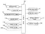
도 6 은 일 실시형태의 노광 장치의 제어계의 주요한 구성을 도시하는 블록도이다.6 is a block diagram showing the main configuration of the control system of the exposure apparatus of one embodiment.
도 7 은 웨이퍼 스테이지 (WST1) 상에 탑재된 웨이퍼에 대해 노광이 행해지고, 웨이퍼 스테이지 (WST2) 상에서는 웨이퍼 교환이 이루어지는 상태를 도시하는 도면이다.Fig. 7 is a diagram showing a state in which exposure is performed on a wafer mounted on the wafer stage WST1, and wafer exchange is performed on the wafer stage WST2.
도 8 은 웨이퍼 스테이지 (WST1) 상에 탑재된 웨이퍼에 대해 노광이 행해지고, 웨이퍼 스테이지 (WST2) 상에 탑재된 웨이퍼에 대해 웨이퍼 얼라이먼트가 행해지는 상태를 도시하는 도면이다.Fig. 8 is a diagram showing a state in which wafer is mounted on the wafer stage WST1 and wafer alignment is performed on the wafer mounted on the wafer stage WST2.
도 9 는 XZ 간섭계 (116) 만을 사용하여 웨이퍼 테이블 (WTB1) 의 X, Z, θy 위치를, XZ 간섭계 (126) 만을 사용하여 웨이퍼 테이블 (WTB2) 의 X, Z, θy 위치를 계측하고 있는 상태를 도시하는 도면이다.9 shows a state in which X, Z, and θy positions of the wafer table WTB1 are measured using only the
도 10 은 웨이퍼 스테이지 (WST1) 와 웨이퍼 스테이지 (WST2) 가 스크럼 상태를 유지하여 이동함으로써, 액침 영역이 웨이퍼 스테이지 (WST1) 상으로부터 웨 이퍼 스테이지 (WST2) 상으로 이동하는 모습을 설명하기 위한 도면이다.10 is a view for explaining how the liquid immersion area moves from the wafer stage WST1 to the wiper stage WST2 by moving the wafer stage WST1 and the wafer stage WST2 while maintaining a scrambled state .
도 11 은 웨이퍼 스테이지 (WST2) 상에 탑재된 웨이퍼에 대해 노광이 행해지고, 웨이퍼 스테이지 (WST1) 상에서는 웨이퍼 교환이 이루어지는 상태를 도시하는 도면이다.11 is a diagram showing a state in which exposure is performed on a wafer mounted on the wafer stage WST2 and wafer exchange is performed on the wafer stage WST1.
도 12 는 웨이퍼 스테이지 (WST1) 와 웨이퍼 스테이지 (WST2) 가 스크럼 상태를 유지하여 이동함으로써, 액침 영역이 웨이퍼 스테이지 (WST2) 상으로부터 웨이퍼 스테이지 (WST1) 상으로 이동하는 모습을 설명하기 위한 도면이다.12 is a view for explaining a state in which the liquid immersion area moves from the wafer stage WST2 to the wafer stage WST1 by moving the wafer stage WST1 and the wafer stage WST2 while maintaining a scrambled state.
도 13 은 변형예에 관한 노광 장치를 설명하기 위한 제 1 도면이다.13 is a first drawing for explaining an exposure apparatus according to a modified example.
도 14 는 변형예에 관한 노광 장치를 설명하기 위한 제 2 도면이다.14 is a second diagram for explaining an exposure apparatus according to a modification.
발명을 실시하기 위한 최선의 형태BEST MODE FOR CARRYING OUT THE INVENTION
이하, 본 발명의 일 실시형태에 대해, 도 1 ∼ 도 12 에 기초하여 설명한다.Hereinafter, an embodiment of the present invention will be described with reference to Figs. 1 to 12. Fig.
도 1 에는, 일 실시형태의 트윈 스테이지형 노광 장치 (100) 의 구성이 개략적으로 도시되어 있다. 노광 장치 (100) 는, 스텝·앤드·스캔 방식의 투영 노광 장치, 이른바 스캐너이다. 후술하는 바와 같이, 본 실시형태에서는 투영 광학계 (PL) 와 얼라이먼트계 (ALG) 가 형성되어 있고, 이하에 있어서는, 투영 광학계 (PL) 의 광축 (AX) 과 평행한 방향을 Z 축 방향, 이것과 직교하는 면내에서 투영 광학계 (PL) 의 중심 (광축 (AX)) 과 얼라이먼트계 (ALG) 의 검출 중심 (광축 (AXp)) 을 연결하는 직선과 평행한 방향을 Y 축 방향, Z 축 및 Y 축과 직교하는 방향을 X 축 방향, X 축, Y 축 및 Z 축 둘레의 회전 (경사) 방향을 각각 θx 방향, θy 방향 및 θz 방향으로 하여 설명한다.Fig. 1 schematically shows a configuration of a twin-stage
노광 장치 (100) 는, 조명계 (10), 레티클 스테이지 (RST), 투영 유닛 (PU), 국소 액침 장치 (8), 얼라이먼트계 (ALG), 스테이지 장치 (50) 및 이들의 제어계 등을 구비하고 있다. 또한, 도 1 에서 스테이지 장치 (50) 를 구성하는 2 개의 웨이퍼 스테이지 (WST1, WST2) 가 각각 투영 유닛 (PU) 의 하방, 얼라이먼트계 (ALG) 의 하방에 위치하고 있다. 또한, 웨이퍼 스테이지 (WST1, WST2) 상에는, 각각 웨이퍼 (W1, W2) 가 탑재되어 있다.The
조명계 (10) 는, 예를 들어 미국 특허 출원 공개 제2003/0025890호 명세서 등에 개시되는 바와 같이, 광원과, 옵티컬 인터그레이터 등을 포함하는 조도 균일화 광학계 및 레티클 블라인드 등을 포함하는 조명 광학계 (모두 도시 생략) 를 가지고 있다. 조명계 (10) 는, 레티클 블라인드 (마스킹 시스템이라고도 불린다) 로 규정된 레티클 (R) 상의 슬릿 형상의 조명 영역 (IAR) 을 조명광 (노광광) (IL) 에 의해 거의 균일한 조도로 조명한다. 여기서, 조명광 (IL) 으로서, 예를 들어, ArF 엑시머 레이저광 (파장 193 ㎚) 이 사용되고 있다.The
레티클 스테이지 (RST) 상에는, 회로 패턴 등이 그 패턴면 (도 1 에서의 하면) 에 형성된 레티클 (R) 이, 예를 들어 진공 흡착에 의해 고정되어 있다. 레티클 스테이지 (RST) 는, 예를 들어 리니어 모터 등을 포함하는 레티클 스테이지 구동계 (11) (도 1 에서는 도시 생략, 도 6 참조) 에 의해, XY 평면 내에서 미소 구동 가능함과 함께, 주사 방향 (여기서는, 도 1 에 있어서의 지면 내 좌우 방향인 Y 축 방향으로 한다) 으로 소정 주사 속도로 구동할 수 있게 되어 있다.On the reticle stage RST, a reticle R in which a circuit pattern or the like is formed on the pattern surface (lower surface in Fig. 1) is fixed, for example, by vacuum adsorption. The reticle stage RST can be finely driven in the XY plane by means of a reticle
레티클 스테이지 (RST) 의 XY 평면 (이동면) 내의 위치 정보 (θz 방향의 회 전 정보를 포함한다) 는, 레티클 레이저 간섭계 (이하, 레티클 간섭계라고 한다) (116) 에 의해, 이동경 (15) (실제로는, Y 축 방향과 직교하는 반사면을 갖는 Y 이동경 (혹은 레트로 리플렉터) 과 X 축 방향과 직교하는 반사면을 갖는 X 이동경이 형성되어 있다) 을 통해, 예를 들어 0.25 ㎚ 정도의 분해능으로 상시 검출된다. 레티클 간섭계 (116) 로부터의 위치 정보는, 주제어 장치 (20) (도 1 에서는 도시 생략, 도 6 참조) 에 보내진다. 주제어 장치 (20) 는, 보내진 위치 정보에 기초하여, 레티클 스테이지 구동계 (11) 를 통해 레티클 스테이지 (RST) 의 위치 (및 속도) 를 제어한다.Position information (including rotation information in the? Z direction) in the XY plane (moving plane) of the reticle stage RST is detected by a reticle laser interferometer (hereinafter referred to as a reticle interferometer) Through a Y movement mirror (or retroreflector) having a reflection surface orthogonal to the Y axis direction and an X movement mirror having a reflection surface orthogonal to the X axis direction), for example, at resolutions of about 0.25 nm . Position information from the
투영 유닛 (PU) 은, 레티클 스테이지 (RST) 의 도 1 에 있어서의 하방 (-Z 방향) 에 배치되어 있다. 투영 유닛 (PU) 은, 경통 (40) 과, 경통 (40) 내에 유지된 투영 광학계 (PL) 를 포함한다. 투영 광학계 (PL) 로는, 예를 들어, Z 축 방향과 평행한 광축 (AX) 을 따라 배열되는 복수의 광학 소자 (렌즈 엘리먼트) 로 이루어지는 굴절 광학계가 사용되고 있다. 투영 광학계 (PL) 는, 예를 들어 양측 텔레센트릭으로, 소정 투영 배율 (예를 들어 1/4 배, 1/5 배 또는 1/8 배 등) 을 갖는다. 이 때문에, 조명계 (10) 로부터의 조명광 (IL) 에 의해 레티클 (R) 상의 조명 영역 (IAR) 이 조명되면, 투영 광학계 (PL) 의 제 1 면 (물체면) 과 패턴면이 거의 일치하여 배치되는 레티클 (R) 을 통과한 조명광 (IL) 에 의해, 투영 광학계 (PL) (투영 유닛 (PU)) 를 통해 그 조명 영역 (IAR) 내의 레티클 (R) 의 회로 패턴의 축소 이미지 (회로 패턴의 일부의 축소 이미지) 가, 투영 광학계의 제 2 면 (이미지면) 측에 배치되는, 표면에 레지스트 (감응제) 가 도포된 웨이퍼 (W1) (또는 W2) 상의 조명 영역 (IAR) 에 공액인 영역 (이하, 노광 영역이라고도 한다) (IA) 에 형성된다. 그리고, 레티클 스테이지 (RST) 와 웨이퍼 스테이지 (WST1) (또는 WST2) 의 동기 구동에 의해, 조명 영역 (IAR) (조명광 (IL)) 에 대해 레티클 (R) 을 주사 방향 (Y 축 방향) 으로 상대 이동시킴과 함께, 노광 영역 (조명광 (IL)) 에 대해 웨이퍼 (W1) (또는 W2) 를 주사 방향 (Y 축 방향) 으로 상대 이동시킴으로써, 웨이퍼 (W1) (또는 W2) 상의 하나의 쇼트 영역 (구획 영역) 의 주사 노광이 행해지고, 그 쇼트 영역에 레티클 (R) 의 패턴이 전사된다. 즉, 본 실시형태에서는 조명계 (10), 레티클 (R) 및 투영 광학계 (PL) 에 의해 웨이퍼 (W1) (또는 W2) 상에 패턴이 생성되고, 조명광 (IL) 에 의한 웨이퍼 (W1) (또는 W2) 상의 감응층 (레지스트층) 의 노광에 의해 웨이퍼 (W1) (또는 W2) 상에 그 패턴이 형성된다.The projection unit PU is disposed downward (-Z direction) in Fig. 1 of the reticle stage RST. The projection unit PU includes a
본 실시형태의 노광 장치 (100) 에는, 액침 방식의 노광을 행하기 위해서 국소 액침 장치 (8) 가 형성되어 있다. 국소 액침 장치 (8) 는, 액체 공급 장치 (5), 액체 회수 장치 (6) (모두 도 1 에서는 도시 생략, 도 6 참조), 액체 공급관 (31A), 액체 회수관 (31B) 및 노즐 유닛 (32) 등을 포함한다. 노즐 유닛 (32) 은, 도 1 에 도시하는 바와 같이, 투영 광학계 (PL) 를 구성하는 가장 이미지면측 (웨이퍼측) 에 가까운 광학 소자, 여기서는 렌즈 (이하, 선단(先端) 렌즈라고도 한다) (191) 를 유지하는 경통 (40) 의 하단부 주위를 둘러싸도록, 투영 유닛 (PU) 을 유지하는 도시 생략된 메인 프레임에 매달려 지지되어 있다. 본 실시형태에서는, 노즐 유닛 (32) 은, 도 1 에 도시하는 바와 같이, 그 하단면이 선단 렌즈 (191) 의 하단면과 거의 동일면에 설정되어 있다.In the
액체 공급관 (31A) 은 액체 공급 장치 (5) (도 1 에서는 도시 생략, 도 6 참조) 에, 액체 회수관 (31B) 은 액체 회수 장치 (6) (도 1 에서는 도시 생략, 도 6 참조) 에 접속되어 있다. 여기서, 액체 공급 장치 (5) 에는, 액체를 저장하는 탱크, 가압 펌프, 온도 제어 장치, 액체의 유량을 제어하기 위한 밸브 등이 구비되어 있다. 액체 회수 장치 (6) 에는, 회수한 액체를 저장하는 탱크, 흡인 펌프, 액체의 유량을 제어하기 위한 밸브 등이 구비되어 있다.The
주제어 장치 (20) 는, 액체 공급 장치 (5) (도 6 참조) 를 제어하여, 액체 공급관 (31A) 을 통해 선단 렌즈 (191) 와 웨이퍼 (W1) (또는 W2) 사이에 액체 (Lq) 를 공급함과 함께, 액체 회수 장치 (6) (도 6 참조) 를 제어하여, 액체 회수관 (31B) 을 통해 선단 렌즈 (191) 와 웨이퍼 (W1) (또는 W2) 사이로부터 액체 (Lq) 를 회수한다. 이 때, 주제어 장치 (20) 는, 공급되는 액체의 양과 회수되는 액체의 양이 상시 동일해지도록, 액체 공급 장치 (5) 와 액체 회수 장치 (6) 를 제어한다. 따라서, 선단 렌즈 (191) 와 웨이퍼 (W1) (또는 W2) 사이에는, 일정량의 액체 (Lq) 가 상시 교체되어 유지되고, 그로 인해 액침 영역 (14) (도 4 등 참조) 이 형성된다. 본 실시형태의 노광 장치 (100) 에서는, 조명광 (IL) 을, 액침 영역 (14) 을 형성하는 액체 (Lq) 를 통해 웨이퍼 (W1) (또는 W2) 에 조사함으로써, 웨이퍼 (W1) (또는 W2) 에 대한 노광이 행해진다. 여기서, 액침 영역 (14) 은, 액침 공간이라고도 하는 액체 (Lq) 로 채워진 3차원 공간인데, 공간은 공극도 의미하므로, 이러한 오해를 피하기 위해, 본 명세서에서는 액침 영역이라는 용어를 사용하고 있다.The
상기 액체로서, 예를 들어 ArF 엑시머 레이저광 (파장 193 ㎚ 의 광) 이 투과하는 순수가 사용된다. 또한, ArF 엑시머 레이저광에 대한 순수의 굴절률 n 은 거의 1.44 이고, 순수 중에서는, 조명광 (IL) 의 파장은 193 ㎚ × 1/n = 약 134 ㎚ 로 단파장화된다.As the liquid, for example, pure water through which ArF excimer laser light (light having a wavelength of 193 nm) is transmitted is used. Further, the refractive index n of the pure water with respect to the ArF excimer laser light is approximately 1.44, and in pure water, the wavelength of the illumination light IL is shortened to 193 nm x 1 / n = approximately 134 nm.
얼라이먼트계 (ALG) 는, 투영 유닛 (PU) 의 중심 (투영 광학계 (PL) 의 광축 (AX) (본 실시형태에서는, 전술한 노광 영역 (IA) 의 중심과 일치)) 으로부터 -Y 측으로 소정 거리 떨어진 위치에 배치되고, 도시 생략된 메인 프레임에 고정되어 있다. 여기서, 얼라이먼트계 (ALG) 로서, 예를 들어 화상 처리 방식의 FIA (Field Image Alignment) 계가 사용된다. 얼라이먼트계 (ALG) 는, 웨이퍼 얼라이먼트 등에 있어서, 주제어 장치 (20) 의 지시에 따라 웨이퍼 스테이지 (WST1 또는 WST2) 상의 기준 마크 또는 웨이퍼 상의 얼라이먼트 마크 (웨이퍼 마크) 를 촬상하고, 그 촬상 신호를 도시 생략된 신호 처리계를 통해 주제어 장치 (20) 에 공급한다 (도 6 참조).The alignment system ALG has a predetermined distance from the center of the projection unit PU (the optical axis AX of the projection optical system PL (corresponding to the center of the above described exposure area IA in this embodiment)) to the -Y side And is fixed to a main frame (not shown). Here, as the alignment system (ALG), for example, an FIA (Field Image Alignment) system of an image processing method is used. The alignment system ALG picks up a reference mark on the wafer stage WST1 or WST2 or an alignment mark (wafer mark) on the wafer in accordance with an instruction from the
그 밖에, 본 실시형태에서의 노광 장치 (100) 에는, 투영 유닛 (PU) 의 근방에, 예를 들어 미국 특허 제5,448,332 호 명세서 등에 개시되는 바와 동일한 구성의 경사 입사 방식의 다점 초점 위치 검출계 (이하, 다점 AF 계라고 약술한다) (AF) (도 1 에서는 도시 생략, 도 6 참조) 가 형성되어 있다. 여기서, 다점 AF 계 (AF) 로는, 조사계로부터의 검출빔을, 전술한 노즐 유닛 (32) 에 형성된 도시 생략된 광투과부 및 액침 영역의 액체 (Lq) 를 통해 웨이퍼 (W1) (또는 W2) 표면의 복수의 검출점에 각각 조사하고, 복수의 검출점 각각에 있어서의 검출빔의 반사광을 노즐 유닛 (32) 에 형성된 별도의 광투과부를 통해 수광계로 수광하는 구성이 사용되고 있다. 다점 AF 계 (AF) 의 검출 신호는, 도시 생략된 AF 신호 처리계를 통해 주제어 장치 (20) 에 공급된다 (도 6 참조). 주제어 장치 (20) 는, 다점 AF 계의 검출 신호에 기초하여, 각 검출점에 있어서의 웨이퍼 (W) 표면의 Z 축 방향의 위치 정보를 검출하고, 그 검출 결과에 기초하여 주사 노광 중의 웨이퍼 (W) 의 이른바 포커스·레벨링 제어를 실행한다. 또한, 얼라이먼트 검출계 (ALG) 의 근방에 다점 AF 계를 형성하고, 웨이퍼 얼라이먼트시에 웨이퍼 표면의 면위치 정보 (요철 정보) 를 사전에 취득하고, 노광시에는 그 면위치 정보와 웨이퍼 스테이지 상면의 Z 축 방향의 위치를 검출하는 별도의 센서의 계측값을 사용하여, 웨이퍼 (W) 의 이른바 포커스·레벨링 제어를 실행하게 해도 된다.In addition, the
또한, 노광 장치 (100) 에서는, 레티클 스테이지 (RST) 의 상방에 노광 파장의 광을 사용한 1 쌍의 TTR (Through The Reticle) 얼라이먼트계로 이루어지는 레티클 얼라이먼트 검출계 (13) (도 1 에서는 도시 생략, 도 6 참조) 가 형성되어 있다. 레티클 얼라이먼트 검출계 (13) 의 검출 신호는, 도시 생략된 얼라이먼트 신호 처리계를 통해 주제어 장치 (20) 에 공급된다 (도 6 참조).In the
스테이지 장치 (50) 는, 도 1 에 도시하는 바와 같이, 베이스반 (12) 의 상방에 배치된 웨이퍼 스테이지 (WST1, WST2), 웨이퍼 스테이지 (WST1, WST2) 의 위치 정보를 계측하는 간섭계 시스템 (118) 을 포함하는 계측 시스템 (200) (도 6 참조) 및 웨이퍼 스테이지 (WST1, WST2) 를 구동시키는 스테이지 구동계 (124) (도 6 참조) 등을 구비하고 있다. 웨이퍼 스테이지 (WST1, WST2) 는, 각각이 구비하는 후술하는 에어 슬라이더에 의해, 수 ㎛ 정도의 클리어런스를 통해, 베이스반 (12) 의 상방에 부상 지지되어 있다. 그리고, 웨이퍼 스테이지 (WST1, WST2) 는, 스테이지 구동계 (124) 를 구성하는 후술하는 평면 모터에 의해, 각각 베이스반 (12) 의 상면 (이동 가이드면) 을 따라 XY 평면 내에서 구동할 수 있다.1, the
웨이퍼 스테이지 (WST1) 는, 도 1 및 도 2(A) 에 도시하는 바와 같이, 스테이지 본체 (91) 와, 스테이지 본체 (91) 상에 탑재된 웨이퍼 테이블 (WTB1) 을 포함한다. 스테이지 본체 (91) 는, 도 2(A) 에 도시하는 바와 같이, 베이스반 (12) 의 내부에 매립된 고정자 (52) 와 함께, 평면 모터 (51) 를 구성하는 가동자 (56) 와, 그 가동자 (56) 의 하반부의 주위에 일체적으로 형성되고, 복수의 에어 베어링을 갖는 에어 슬라이더 (54) 를 가지고 있다.The wafer stage WST1 includes a stage
가동자 (56) 는, 예를 들어 서로 이웃하는 자극면의 극성이 서로 상이하도록 매트릭스 형상으로 배열된 복수의 평판 자석으로 구성된 평판 상의 발자체 (發磁體) 를 포함하는 자석 유닛에 의해 구성되어 있다.The
한편, 고정자 (52) 는, 베이스반 (12) 의 내부에 매트릭스 형상으로 배열된 복수의 전기자 코일 (구동 코일) (57) 을 갖는 전기자 유닛에 의해 구성되어 있다. 전기자 코일 (57) 로서, 본 실시형태에서는, X 구동 코일 및 Y 구동 코일이 형성되어 있다. 그리고, 복수의 X 구동 코일 및 Y 구동 코일을 포함하는 전기자 유닛으로 이루어지는 고정자 (52) 와, 전술한 자석 유닛으로 이루어지는 가동자 (56) 에 의해, 전자력 구동 방식 (로렌츠 힘 구동 방식) 의 무빙 마그넷형의 평면 모터 (51) 가 구성되어 있다.On the other hand, the stator 52 is constituted by an armature unit having a plurality of armature coils (drive coils) 57 arranged in a matrix form in the
복수의 전기자 코일 (57) 은, 베이스반 (12) 의 상면을 구성하는 평판 형상 부재 (58) 에 의해 커버된다. 평판 형상 부재 (58) 의 상면은, 웨이퍼 스테이지 (WST1) (및 WST2) 의 이동 가이드면 또한 에어 슬라이더 (54) 가 구비하는 에어 베어링으로부터의 가압 공기의 수압면을 구성한다.The plurality of armature coils 57 are covered by the flat plate-
웨이퍼 테이블 (WTB1) 은, 스테이지 본체 (91) 상에 스테이지 구동계 (124) 의 일부를 구성하는 Z·레벨링 기구 (예를 들어, 보이스 코일 모터 등을 포함한다) 를 통해 설치되어 있다. 웨이퍼 테이블 (WTB1) 은, Z·레벨링 기구에 의해, 스테이지 본체 (91) 에 대해 Z 축 방향, θx 방향 및 θy 방향으로 미소 구동된다. 따라서, 웨이퍼 테이블 (WTB1) 은, 평면 모터 (51) 와 Z·레벨링 기구를 포함하는 스테이지 구동계 (124) 에 의해, 베이스반 (12) 에 대해, 6 자유도 방향 (X, Y, Z, θx, θy, θz) 으로 구동할 수 있게 구성되어 있다.The wafer table WTB1 is provided on the stage
웨이퍼 테이블 (WTB1) 의 상면의 중앙에는, 웨이퍼를 진공 흡착 등에 의해 유지하는 웨이퍼 홀더 (도시 생략) 가 형성되어 있다. 웨이퍼 홀더 (웨이퍼의 탑재 영역) 의 외측에는, 도 2(B) 에 도시하는 바와 같이, 웨이퍼 홀더보다 한둘레 큰 원형의 개구가 중앙에 형성되고, 또한 직사각형 형상의 외형 (윤곽) 을 갖는 플레이트 (28) 가 형성되어 있다. 플레이트 (28) 의 표면은, 액체 (Lq) 에 대해 발액화 처리되어 발액면을 형성하고 있다. 또한, 플레이트 (28) 는, 그 표면의 전부 (혹은 일부) 가 웨이퍼 (W) 의 표면과 거의 동일면이 되도록 설정되어 있다.At the center of the upper surface of the wafer table WTB1, a wafer holder (not shown) for holding the wafer by vacuum suction or the like is formed. As shown in Fig. 2 (B), on the outer side of the wafer holder (wafer mounting area), a plate having a circular opening at one center than the wafer holder at the center and having a rectangular outer shape (contour) 28 are formed. The surface of the
또한, 플레이트 (28) 의 +Y 측의 거의 중앙에는, 원형 개구가 형성되고, 그 원형 개구 내에는 기준 마크판 (FM) 이 끼워져 들어가 있다. 기준 마크판 (FM) 은, 그 표면이 플레이트 (28) 와 거의 동일면으로 되어 있다. 기준 마크판 (FM) 의 표면에는, 레티클 얼라이먼트 검출계 (13) 에 의해 검출되는 1 쌍의 제 1 기준 마크와, 얼라이먼트계 (ALG) 에 의해 검출되는 제 2 기준 마크가 적어도 형성되어 있다.Further, a circular opening is formed in the substantially center of the
웨이퍼 테이블 (WTB1) 의 -Y 측의 +X 단부 (端部) 에는, 도 2(B) 에 도시하는 바와 같이, 다른 부분보다 돌출된 판 형상의 차양부 (庇部) (23a) 가 형성되어 있다. 또한, 웨이퍼 테이블 (WTB1) 의 +Y 측의 +X 단부에는, 도 2(B) 에 도시하는 바와 같이, 차양부 (23a) 와 X 축 방향의 폭이 거의 동일한 단차부 (평면에서 보았을 때 직사각형의 절제부) (23b) 가 형성되어 있다. 웨이퍼 테이블 (WTB1) 의 상면은, 웨이퍼 (W1) 및 차양부 (23a) 를 포함하여, 거의 전체면 (단차부 (23b) 를 제외한다) 이 거의 동일면이 되어 있다.As shown in Fig. 2 (B), a plate-
웨이퍼 스테이지 (WST2) 는, 도 1 (및 도 4) 등에 도시하는 바와 같이, 스테이지 본체 (91) 와, 웨이퍼 테이블 (WTB2) 을 포함하고, 상기 서술한 웨이퍼 스테이지 (WST1) 와, 좌우 대칭이지만 완전히 동일하게 구성되어 있다.The wafer stage WST2 includes a stage
따라서, 웨이퍼 테이블 (WTB2) 에는, -Y 측의 -X 단부에 차양부 (23a) 와 동일한 (혹은 좌우 대칭인) 차양부가 형성되고, +Y 측의 -X 단부에 단차부 (23b) 와 좌우 대칭인 단차부 (평면에서 보았을 때 직사각형의 절제부) 가 형성되어 있다. 이하에서는, 식별을 위해 웨이퍼 테이블 (WTB2) 이 구비하는 차양부를 차양부 23a' 로 단차부를 23b' 로 기술하기로 한다.Therefore, the wafer table WTB2 is provided with the same (or left-right symmetrical) oblique portion as the
여기서, 차양부 (23a, 23a') 및 단차부 (23b, 23b') 에 대해, 상세히 서술한다. 도 3(A) 에는, 웨이퍼 테이블 (WTB1) 에 형성된 단차부 (23b) 와, 웨이퍼 테이블 (WTB2) 에 형성된 차양부 (23a') 가 확대되어 도시되어 있다. 이 도 3(A) 에 도시된 바와 같이, 웨이퍼 테이블 (WTB2) 에 형성된 차양부 (23a') 의 선단과 웨이퍼 테이블 (WTB2) 에 형성된 단차부 (23b) 가 걸어맞추어짐으로써, 웨이퍼 스테이지 (WST1) 의 +Y 측의 면과 웨이퍼 스테이지 (WST2) 의 -Y 측의 면이 일부 대향한 상태에서, 웨이퍼 스테이지 (WST1) 와 웨이퍼 스테이지 (WST2) 가 차양부 (23a') 및 단차부 (23b) 를 통해, Y 축 방향에 대해 근접 또는 접촉할 수 있는, 즉 양 웨이퍼 스테이지 (WST1, WST2) 가 스크럼 상태가 되게 되어 있다 (도 4 참조).Here, the
웨이퍼 테이블 (WTB2) 의 차양부 (23a') 의 Y 축 방향의 길이는, 단차부 (23b) 의 Y 축 방향의 길이보다 현격히 길게 설정되고, 도 3(A) 에 도시하는 바와 같이, 차양부 (23a') 와 단차부 (23b) 가 걸어맞추어진 상태에서, 웨이퍼 스테이지 (WST1) 와 웨이퍼 스테이지 (WST2) 가 접촉하는 (보다 정확하게는, 웨이퍼 스테이지 (WST1) 의 에어 슬라이더 (54) 의 +Y 측단과 웨이퍼 스테이지 (WST2) 의 에어 슬라이더 (54) 의 -Y 측단이 접촉하는) 것을 저지할 수 있을 정도의 길이로 설정되어 있다.The length of the
웨이퍼 테이블 (WTB1) 의 차양부 (23a) 와, 웨이퍼 테이블 (WTB2) 의 단차부 (23b') 는, 상기 차양부 (23a'), 단차부 (23b) 와 동일한 치수를 가져, 동일하게 서로 걸어맞출 수 있다. 그리고, 그들의 걸어맞춤 상태에서는, 웨이퍼 스테이 지 (WST1) 와 웨이퍼 스테이지 (WST2) 가 접촉하는 (보다 정확하게는, 웨이퍼 스테이지 (WST1) 의 에어 슬라이더 (54) 의 -Y 측단과, 웨이퍼 스테이지 (WST2) 의 에어 슬라이더 (54) 의 +Y 측단이 접촉하는) 것을 저지할 수 있게 되어 있다.The
본 실시형태에서는, 웨이퍼 스테이지 (WST1, WST2) 가, 보다 정확하게는, 차양부 (23a') 와 단차부 (23b) 가 (또는 차양부 (23a) 와 단차부 (23b') 가) 근접 또는 접촉하는 상태 (양 웨이퍼 스테이지의 스크럼 상태) 에서는, 웨이퍼 테이블 (WTB1) 과 웨이퍼 테이블 (WTB2) 의 상면은, 차양부 (23a) (또는 23a') 의 상면을 포함하여, 전체적으로 거의 동일면 (풀 플랫인 면) 이 된다 (도 3(A) 참조). 여기서, 차양부 (23a') (또는 23a) 와 단차부 (23b) (또는 23b') 가 근접한다는 것은, 일례로서 300㎛ 정도의 클리어런스를 통해 차양부 (23a') (또는 23a) 와 단차부 (23b) (또는 23b') 가 접근하는 상태를 의미한다.In this embodiment, the wafer stages WST1 and WST2 are more accurately positioned so that the
차양부 (23a') (및 23a) 의 X 축 방향의 폭은, 도 4 에 도시하는 바와 같이, 전술한 액침 영역 (14) 의 폭보다 충분히 크고, 예를 들어 100 ㎜ 정도, 정확하게는 100 ㎜ 이하 (일례로서 80 ㎜ ∼ 100 ㎜) 로 설정되어 있다. 따라서, 예를 들어, 웨이퍼 테이블 (WTB1) 에 탑재된 웨이퍼 (W1) 에 대한 노광이 종료되고, 웨이퍼 테이블 (WTB2) 에 탑재된 웨이퍼 (W2) 에 대한 노광을 개시하기 위해서는, 액침 영역 (14) 이 형성되는 투영 광학계 (PL) 하방의 영역을 포함하는 노광시 이동 영역 (AE) (도 7 및 도 8 참조) 에 위치하는 웨이퍼 스테이지 (WST1) 를 노광시 이동 영역 (AE) 으로부터 퇴피시키고, 소정 대기 위치에서 대기하고 있는 웨이퍼 스테이지 (WST2) 를 노광시 이동 영역 (AE) 으로 이동시켜야 한다. 그 때, 주제 어 장치 (20) 는, 예를 들어 도 10 에 도시하는 바와 같이, 웨이퍼 스테이지 (WST1, WST2) 를, 각각이 갖는 단차부 (23b) 와 차양부 (23a') 를 걸어맞추어, Y 축 방향으로 근접 또는 접촉시킨다. 그리고, 이 상태 (스크럼 상태) 를 유지한 채로, 주제어 장치 (20) 가 양 웨이퍼 스테이지 (WST1, WST2) 를 -Y 방향으로 구동시킴으로써, 액침 영역 (14) 은, 웨이퍼 테이블 (WTB1), 차양부 (23a') 및 웨이퍼 테이블 (WTB2) 의 상면을 순차적으로 이동한다.4, the width of the
액침 영역 (14) 이 차양부 (23a') 를 통해, 웨이퍼 테이블 (WTB1) 상으로부터 웨이퍼 테이블 (WTB2) 상으로 이동할 때 (또는, 차양부 (23a) 를 통해 웨이퍼 테이블 (WTB2) 상으로부터 웨이퍼 테이블 (WTB1) 상으로 이동할 때), 액침 영역 (14) 을 형성하는 액체 (Lq) 가 차양부 (23a') 와 단차부 (23b) 의 간극 (또는 차양부 (23a) 와 단차부 (23b') 의 간극) 에 침입하고, 웨이퍼 스테이지 (WST1 및/또는 WST2) 의 측면을 통해 웨이퍼 스테이지 (WST1 및/또는 WST2) 의 하방으로 누출되는 경우가 일어날 수 있다. 그래서, 예를 들어, 도 3(C) 에 도시하는 바와 같이, 단차부 (23b) 의 차양부 (23a') 와 걸어맞추는 면의 일부에, 반대로 차양부 (23a') 의 단차부 (23b) 와 걸어맞추는 면의 일부에, 혹은 차양부 (23a') 와 단차부 (23b) 의 양방이 걸어맞춰지는 면의 일부에, 시일 부재 (24) 를 부착하면 된다. 이러한 경우에는, 시일 부재 (24) 에 의해, 액체 (Lq) 의 차양부 (23a') 와 단차부 (23b) 의 간극에 대한 침수, 나아가서는 웨이퍼 스테이지 (WST1 및/또는 WST2) 의 하방에 대한 누출을 방지할 수 있다. 또한, 시일 부재 (24) 로는, 예를 들어 불소 고무 등으로 이루어지는 탄성 시일 부재가 사용된다. 또한, 시일 부재 (24) 를 부착하는 대신, 차양부 (23a') 의 단차부 (23b) 와의 걸어맞춤면 및/또는 단차부 (23b) 의 차양부 (23a') 와의 걸어맞춤 면에, 테플론 (등록 상표) 등에 의해 발수 코트를 실시해도 된다. 또한, 단차부 (23b'), 차양부 (23a) 에 대해서도 상기와 동일하다.When the
본 실시형태에서는, 상기 서술한 바와 같이, 액침 영역 (14) 을, 차양부 (23a 또는 23a') 를 통해 웨이퍼 테이블 (WTB1, WTB2) 사이에서 이동시킬 수 있다. 이 때, 차양부 (23a) 와 단차부 (23b') 가 (또는 차양부 (23a') 와 단차부 (23b) 가) 접촉 또는 근접한 상태가 유지되므로, 차양부와 단차부의 간극으로부터 액침 영역 (14) 의 액체 (Lq) 가 누출되는 것도 방지할 수 있다. 따라서, 투영 광학계 (PL) 의 하방으로부터의 액체 (Lq) 의 회수 작업이 불필요해져, 액체 (Lq) 의 회수, 공급을 실시하는 경우에 비해 스루풋이 향상될 수 있게 된다.In this embodiment, as described above, the
또한, 상기 서술한 설명에서는, 웨이퍼 테이블 (WTB1, WTB2) 의 -Y 측의 단부에 차양부를, +Y 측의 단부에 단차부를 각각 형성하기로 했지만, 반대로, 후술하는 변형예와 같이, 웨이퍼 테이블 (WTB1, WTB2) 의 +Y 측의 단부에 차양부를, -Y 측의 단부에 단차부를 각각 형성하는 것으로 해도 된다. 그 밖에, 도 3(B) 에 도시하는 바와 같이, 웨이퍼 테이블 (WTB1) 의 상단부의 +Y 측, 웨이퍼 테이블 (WTB2) 의 상단부의 -Y 측에, 서로 걸어맞춰지는 1 쌍의 평판 상의 돌출부 (23c, 23d) 를 형성하는 것으로 해도 된다. 이 경우, 일방의 돌출부 (23c) 의 선단부에 상반부가 하반부에 비해 돌출된 볼록부를 형성하고, 타방의 돌출부 (23d) 의 선단부에는 돌출부 (23c) 의 볼록부에 걸어맞추며, 그 걸어맞춤 상태에서는, 도 3(B) 에 도시하는 바와 같이, 전체적으로 1 개의 판 형상부를 형성하고, 하반부가 상반부에 비해 돌출된 볼록부를 형성하는 것으로 해도 된다. 이 경우에도, 돌출부 (23c, 23d) 가 끼워맞춘 양 웨이퍼 스테이지 (WST1, WST2) 의 스크럼 상태에 있어서, 웨이퍼 스테이지 (WST1) 와 웨이퍼 스테이지 (WST2) 의 접촉을 회피할 수 있는 길이로 돌출부 (23c, 23d) 의 길이가 설정되어 있으면 된다. 물론, 웨이퍼 테이블 (WTB2) 의 상단부의 +Y 측, 웨이퍼 테이블 (WTB1) 의 상단부의 -Y 측에 서로 걸어맞추는 1 쌍의 평판 상의 돌출부를 형성하는 것으로 해도 된다.In the above description, the wafer table WTB1 and the wafer table WTB2 are provided with a flange portion at the end on the -Y side and a step portion on the end portion on the + Y side respectively. In contrast, A wedge portion may be formed at the end on the + Y side of the wirings WTB1 and WTB2, and a step portion may be formed on the end of the -Y side. In addition, as shown in Fig. 3 (B), on the + Y side of the upper end of the wafer table WTB1 and the -Y side of the upper end of the wafer table WTB2, a pair of flat plate- 23c, and 23d may be formed. In this case, the upper half of the one projecting
또한, 본 실시형태에서는, 서로 걸어맞추는 차양부 (23a) (또는 23a') 와 단차부 (23b') (또는 23b) (혹은 1 쌍의 돌출부 (23c, 23d) 를, 웨이퍼 스테이지 (WST1, WST2) 각각의 근접 또는 접촉시 (스크럼시) 에 대향하는 ±Y 측의 ±X 측 단부에 형성하고, 양 웨이퍼 스테이지 (WST1, WST2) 가 X 축 방향에 대해 어긋난 상태에서 스크럼 상태가 되는 것으로 하였다. 이것은, 주로 다음의 a. ∼ c. 의 이유를 고려한 것이다.In the present embodiment, the
a. 웨이퍼의 노광이 행해지는 노광 위치 (액침 영역 (14)) 와 웨이퍼의 얼라이먼트를 실시하는 위치를 연결하는 방향인 Y 축 방향에 대해, 양 웨이퍼 스테이지 (WST1, WST2) 를 스크럼시킴 (근접 또는 접촉시킴) 으로써, 양 웨이퍼 스테이지 (WST1, WST2) 를 X 축 방향에 대해 스크럼시키는 경우에 비해, 양 웨이퍼 스테이지 (WST1, WST2) 의 이동 거리 (이동 스트로크) 를 짧게 할 수 있다. 이로써, 스루풋의 향상을 도모할 수 있게 된다.a. The wafer stage WST1 and the wafer stage WST2 are scratched (brought close to or brought into contact with each other) with respect to the Y-axis direction, which is a direction connecting the exposure position (the liquid immersion area 14) where exposure of the wafer is performed The moving distance (moving stroke) of both wafer stages WST1 and WST2 can be shortened as compared with the case where both wafer stages WST1 and WST2 are scratched with respect to the X axis direction. As a result, it is possible to improve the throughput.
b. 양 웨이퍼 스테이지 (WST1, WST2) 가 X 축 방향에 대해 어긋난 상태에서 스크럼 상태가 되게 함으로써, 양 웨이퍼 스테이지 (WST1, WST2) 의 이동 스트로크를 보다 더욱 짧게 할 수 있고, 이로써 스루풋을 더욱 향상시킬 수 있다.b. The moving strokes of both wafer stages WST1 and WST2 can be further shortened by causing the both wafer stages WST1 and WST2 to be in the state of being scrambled in the state of being displaced with respect to the X-axis direction, thereby further improving the throughput .
c. 웨이퍼 스테이지 (WST1, WST2) 각각에 접속되어 있는 후술하는 케이블의 길이를 짧게 할 수 있다.c. The length of a cable, which will be described later, connected to each of the wafer stages WST1 and WST2 can be shortened.
또한, 웨이퍼 스테이지 (WST1, WST2) 에, 예를 들어 국제 공개 제2007/097379호 팜플렛에 개시되어 있는 공간 이미지 계측 장치, 컨피덴셜바 (CD 바), 조도 불균일 센서, 공간 이미지 계측기, 파면 수차 계측기 및 조도 모니터 등의 각종 계측 장치 및 계측 부재를 설치해도 된다.In addition, the wafer stage WST1, WST2 is provided with a spatial image measuring device, a public bar (CD bar), an illuminance unevenness sensor, a spatial image measuring device, a wavefront aberration measuring device, Various measuring devices such as an illuminance monitor and measuring members may be provided.
본 실시형태에서는, 웨이퍼 스테이지 (WST1) 의 -X 측 단부로부터, 베이스반 (12) (웨이퍼 스테이지 (WST1, WST2) 의 이동 가이드면) 의 -X 측에 설치된 Y 축 방향으로 이동할 수 있는 제 1 케이블 셔틀 (도시 생략) 에, 도시 생략된 배선·배관용 케이블이 접속되어 있다. 마찬가지로, 웨이퍼 스테이지 (WST2) 의 +X 측 단부로부터, 베이스반 (12) 의 +X 측에 설치된 Y 축 방향으로 이동할 수 있는 제 2 케이블 셔틀 (도시 생략) 에, 도시 생략된 배선·배관용 케이블이 접속되어 있다. 이들의 케이블에 의해, 양 웨이퍼 스테이지 (WST1, WST2) 에 형성된 Z·레벨링 기구 및 계측 장치에 대한 전력 공급 및 에어 슬라이더에 대한 가압 공기의 공급 등이 이루어진다.In the present embodiment, the first X-axis direction movable from the -X side end of the wafer stage WST1 to the -X side of the base half 12 (the movement guide surfaces of the wafer stages WST1 and WST2) A wiring and piping cable (not shown) is connected to a cable shuttle (not shown). Likewise, a second cable shuttle (not shown) capable of moving in the Y axis direction provided on the + X side of the
다음으로, 계측 시스템 (200) 의 일부를 구성하는 간섭계 시스템 (118) 에 대해 설명한다.Next, the
도 2(B) 에, 웨이퍼 테이블 (WTB1) 을 사용하여, 대표적으로 도시하는 바와 같이 웨이퍼 테이블 (WTB1, WTB2) 의 -X 측 단면, +Y 측 단면, +X 측 단면, -Y 측 단면에는, 각각 반사면 (27a, 27b, 27c, 27d) 이 형성되어 있다. 또한, 웨이퍼 스테이지 (WST1, WST2) 의 -X 측 및 +X 측의 면에는, 반사면 (27a, 27c) 의 각각에 대해 45 도 경사진 반사면을 갖는 반사 미러 (27e, 27f) 가 형성되어 있다 (도 5 참조). 또한, 도 1 및 도 4 에 도시하는 바와 같이, 직사각형 판 형상의 고정경 (25A, 25C, 25B, 25D) 이 투영 유닛 (PU) 의 +X 측, -X 측 및 얼라이먼트계 (ALG) 의 +X 측, -X 측에 각각의 길이 방향을 X 축 방향으로 향하게 하고, 또한 각각의 반사면을 -Z 방향으로 향하게 하여 배치되어 있다. 고정경 (25A, 25C, 25B, 25D) 의 반사면은, 웨이퍼 스테이지 (WST1 또는 WST2) (웨이퍼 테이블 (WTB1 또는 WST2)) 에 대향할 수 있다. 고정경 (25A ∼ 25D) 은, 투영 유닛 (PU) 등을 유지하는 메인 프레임의 하면에 설치되어 있다.2 (B), the wafer table WTB1 is used to represent the -X side end face, the + Y side end face, the + X side end face, and the -Y side end face of the wafer tables WTB1 and WTB2 And reflection surfaces 27a, 27b, 27c, and 27d, respectively. Reflection mirrors 27e and 27f having reflection surfaces inclined at 45 degrees with respect to the reflection surfaces 27a and 27c are formed on the -X side and the + X side surfaces of the wafer stages WST1 and WST2, respectively (See FIG. 5). As shown in Fig. 1 and Fig. 4, the fixed
간섭계 시스템 (118) 은, 도 4 에 도시하는 바와 같이, 4 개의 Y 간섭계 (16, 17, 18, 19) 와, 4 개의 XZ 간섭계 (116, 117, 126, 127) 를 포함한다. Y 간섭계 (16, 17, 18) 는, 베이스반 (12) 의 +Y 측에 X 축 방향에 대해 상이한 위치에 배치되어 있다. Y 간섭계 (19) 는, 베이스반 (12) 의 -Y 측에 Y 간섭계 (17) 에 대향하여 배치되어 있다. XZ 간섭계 (116, 117) 는, 베이스반 (12) 의 -X 측에 Y 축 방향으로 소정 간격으로 배치되어 있다. 또한, XZ 간섭계 (126, 127) 는 베이스반 (12) 의 +X 측에 XZ 간섭계 (116, 117) 에 각각 대향하여 배치되어 있다.
상세히 서술하면, Y 간섭계 (17) 는, 도 5 에 도시하는 바와 같이, 투영 광 학계 (PL) 의 광축 (AX) 과 얼라이먼트계 (ALG) 의 검출 중심을 연결하는 Y 축과 평행한 직선 (기준축) (LV0) 으로부터 ±X 방향으로 동등한 이간 거리를 간격을 두고, Y 축과 평행한 2 개의 측장빔 (B171, B172) 을 웨이퍼 스테이지 (WST1) (또는 WST2) 의 반사면 (27b) 에 조사하고, 측장빔 (B171, B172) 의 반사광을 수광하여, 측장빔 (B171, B172) 의 조사점에서의 반사면 (27b) 의 Y 축 방향의 변위 (제 1, 제 2 위치 정보로 한다) 를 계측한다. 제 1, 제 2 위치 정보는, 주제어 장치 (20) 에 보내진다. 주제어 장치 (20) 는, 제 1, 제 2 위치 정보의 평균값에 기초하여, 웨이퍼 스테이지 (WST1) (또는 WST2) 의 Y 축 방향에 관한 위치 (Y 위치) 를 산출한다. 즉, Y 간섭계 (17) 의 Y 축 방향에 관한 실질적인 측장축은, 기준축 (LV0) 에 일치하고 있다. 또한, 주제어 장치 (20) 는, 제 1, 제 2 위치 정보의 차에 기초하여, 웨이퍼 스테이지 (WST1) (또는 WST2) 의 θz 방향의 회전 정보 (요잉량) 를 산출한다.5, the
또한, Y 간섭계 (17) 는, 측장빔 (B171, B172) 으로부터 -Z 방향으로 소정 거리 간격을 두고, 또 1 개의 측장빔 (B173) 을 반사면 (27b) 에 조사하고, 측장빔 (B173) 의 반사광을 수광하여, 측장빔 (B173) 의 조사점에서의 반사면 (27b) 의 Y 축 방향의 변위 (제 3 위치 정보로 한다) 를 계측하고, 주제어 장치 (20) 에 보낸다. 주제어 장치 (20) 는, 제 3 위치 정보와, 제 1, 제 2 위치 정보에 기초하여, 웨이퍼 테이블 (WTB1) (또는 WTB2) 의 θx 방향의 회전 정보 (피칭량) 를 산출 한다.The
Y 간섭계 (16, 18, 19) 는, Y 간섭계 (17) 와 마찬가지로, 웨이퍼 테이블 (WTB1, WTB2) 의 일방 또는 양방의 Y 위치, 피칭량 및 요잉량을 계측하기 위해서 사용된다. Y 간섭계 (16, 18) 는, 각각 기준축 (LV0) 과 평행한 측장축 (LV1, LV2) 을 갖는다. 또한, Y 간섭계 (19) 는, 실질적인 측장축을 기준축 (LV0) 으로 하고, 3 개의 측장빔을 웨이퍼 테이블 (WTB1) (또는 WTB2) 의 반사면 (27d) 에 조사한다.The Y interferometers 16, 18 and 19 are used for measuring the Y position, the pitching amount and the yawing amount of one or both of the wafer tables WTB1 and WTB2, like the
XZ 간섭계 (116, 126) 는, 투영 광학계 (PL) 의 광축 (AX) 과 기준축 (LV0) 과 직교하는 기준축 (LH) 을 X 축 방향에 관한 측장축으로 한다. 즉, XZ 간섭계 (116) 는, 도 5 에 도시하는 바와 같이, 측장축 (LH) 을 따라, 측장빔 (B1161) 을 웨이퍼 테이블 (WTB1) (또는 WTB2) 의 반사면 (27a) 에 조사하고, 반사면 (27a) 에 있어서의 측장빔 (B1161) 의 반사광을 수광하여, 측장빔 (B1161) 의 조사점에 있어서의 반사면 (27a) 의 X 축 방향의 변위 (제 4 위치 정보라고 한다) 를 계측한다. 마찬가지로, XZ 간섭계 (126) 는, 측장축 (LH) 을 따라, 측장빔 (B1261) 을 웨이퍼 테이블 (WTB1) (또는 WTB2) 의 반사면 (27c) 에 조사하고, 반사면 (27c) 에 있어서의 측장빔 (B1261) 의 반사광을 수광하여, 측장빔 (B1261) 의 조사점에서의 반사면 (27c) 의 X 축 방향의 변위 (제 5 위치 정보라고 한다) 를 계측한다. 제 4, 제 5 위치 정보는 주제어 장치 (20) 에 보내진다. 주제어 장치 (20) 는, 제 4, 제 5 위치 정보에 기초하여, 웨이퍼 테이블 (WTB1) (또는 WTB2) 의 X 위치를 산출한다.The
또한, XZ 간섭계 (116) 는, 측장축 (LH) 과 평행하게 측장빔 (Z 측장빔) (B1162) 을 웨이퍼 테이블 (WTB1) (또는 WTB2) 에 형성된 반사 미러 (27e) 의 반사면에 조사한다. 측장빔 (B1162) 은 반사 미러 (27e) 에서 +Z 방향으로 반사되어, 전술한 고정경 (25C) 의 반사면 상에 조사된다. 고정경 (25C) 의 반사면으로부터의 측장빔 (B1162) 의 반사광은, 원래의 광로를 반대로 거슬러 올라가 XZ 간섭계 (116) 에 수광된다. XZ 간섭계 (116) 는, 측장빔 (B1162) 의 광로 길이 (의 변화) 를 계측하고, 그 계측 결과를 주제어 장치 (20) 에 보낸다. 마찬가지로, XZ 간섭계 (126) 는, 측장축 (LH) 과 평행하게 측장빔 (Z 측장빔) (B1262) 을 웨이퍼 테이블 (WTB1) (또는 WTB2) 에 형성된 반사 미러 (27f) 의 반사면에 조사한다. 측장빔 (B1262) 은 반사 미러 (27f) 에서 +Z 방향으로 반사되어, 전술한 고정경 (25A) 의 반사면 상에 조사된다. 고정경 (25A) 의 반사면으로부터의 측장빔 (B1262) 의 반사광은, 원래의 광로를 반대로 거슬러 올라가 XZ 간섭계 (126) 에 수광된다. XZ 간섭계 (126) 는, 측장빔 (B1262) 의 광로 길이 (의 변화) 를 계측하고, 그 계측 결과를 주제어 장치 (20) 에 보낸다.Also,
주제어 장치 (20) 는, 전술한 제 4 위치 정보로부터 얻어지는 측장빔 (B1161) 의 광로 길이와, 측장빔 (B1162) 의 광로 길이의 차로부터, 측장빔 (B1162) 의 반사 미러 (27e) 의 반사면 상의 조사점의 Z 위치 (Ze 라고 표기한다) 를 산출한다.The
또한, 주제어 장치 (20) 는, 전술한 제 5 위치 정보로부터 얻어지는 측장빔 (B1261) 의 광로 길이와, 측장빔 (B1262) 의 광로 길이의 차로부터, 측장빔 (B1262) 의 반사 미러 (27f) 의 반사면 상의 조사점의 Z 위치 (Zf 라고 표기한다) 를 산출한다. 또한 주제어 장치 (20) 는, 2 개의 Z 위치 (Ze, Zf) 의 평균값과의 차로부터, 웨이퍼 테이블 (WTB1) (또는 WTB2) 의 Z 위치와 θy 방향의 회전 정보 (롤링량) 를 산출한다.In addition, the
또한, XZ 간섭계 (116, 126) 는, 도 5 에 도시하는 바와 같이 측장축 (LH) 과 평행하게, 단 측장빔 (B1161, B1261) 으로부터 -Z 방향으로 소정 거리 간격을 두고, 각각 측장빔 (B1163, B1263) 을 반사면 (27a, 27c) 에 조사한다. 그리고, XZ 간섭계 (116, 126) 는, 측장빔 (B1163, B1263) 의 반사광을 수광하여, 측장빔 (B1163, B1263) 의 조사점에 있어서의 반사면 (27a, 27c) 의 X 축 방향의 변위 (제 6, 제 7 위치 정보라고 한다) 를 계측한다. 제 6, 제 7 위치 정보는, 주제어 장치 (20) 에 보내진다. 주제어 장치 (20) 는, 제 4 위치 정보와 제 6 위치 정보에 기초하여, 웨이퍼 테이블 (WTB1) (또는 WTB2) 의 롤링량 (θy1 로 한다) 을 산출한다. 또한, 주제어 장치 (20) 는, 제 5 위치 정보와 제 7 위치 정보에 기 초하여, 웨이퍼 테이블 (WTB1) (또는 WTB2) 의 롤링량 (θy2 로 한다) 을 산출한다. 또한, 주제어 장치 (20) 는, Z 위치 (Ze) 와 상기 롤링량 (θy1) 에 기초하여, 웨이퍼 테이블 (WTB1) (또는 WTB2) 의 Z 위치를 산출한다. 또한, 주제어 장치 (20) 는, Z 위치 (Zf) 와 상기 롤링량 (θy2) 에 기초하여, 웨이퍼 테이블 (WTB1) (또는 WTB2) 의 Z 위치를 산출한다.As shown in Fig. 5, the
단, 측장빔 (B1161, B1163) 의 이간 거리 및 측장빔 (B1261, B1263) 의 이간 거리는, 측장빔 (Z 측장빔) (B1162, B1262) 의 반사 미러 (27e, 27f) 의 반사면 상의 조사점의 X 축 방향의 거리와 비교하여 훨씬 짧다. 따라서, 웨이퍼 테이블 (WTB1) (또는 WTB2) 의 롤링량의 계측 정밀도는, 전술한 Z 측장빔 (B1162, B1262) 을 사용하는 계측에 비해 열등하다. 그래서, 주제어 장치 (20) 는, 웨이퍼 테이블 (WTB1) (또는 WTB2) 의 θy 방향의 위치 정보 (롤링량) 및 Z 위치 계측을 원칙으로 하여 Z 측장빔 (B1162, B1262) 을 사용하는, 즉, 양 XZ 간섭계 (116, 126) 를 사용하여 실시하고, 예외적으로 대체법으로서 XZ 간섭계 (116, 126) 의 어느 일방만을 사용하여 실시하기로 한다. 또한, 대체법의 사용예에 대해서는, 후술한다.The distances between the side beams B1161 and B1163 and the distances between the side beams B1261 and B1263 are set to be the same as the distances between the reflecting
XZ 간섭계 (117, 127) 는, XZ 간섭계 (116, 126) 와 마찬가지로, 웨이퍼 얼라이먼트시 등에 웨이퍼 테이블 (WT1, WT2) 의 X 위치, Z 위치 및 θy 방향의 위치 (롤링량) 를 계측하기 위해서 사용된다. 또한, 계측 방법은, 얼라이먼트계 (ALG) 의 검출 중심에 있어서 기준축 (LV0) 과 직교하는 X 축과 평행한 기준축 (LA) (도 4 참조) 을 측장축으로 하는 점 및 Z 측장빔이 조사되는 고정경으로서 고정경 (25D, 25B) 이 각각 사용되는 점이 상이한 점을 제외하면, XZ 간섭계 (116, 126) 를 사용하는 계측과 동일하다.The
이와 같이, Y 간섭계 (16, 17, 18, 19) 및 XZ 간섭계 (116, 117, 126, 127) 를 포함하는 간섭계 시스템 (118) 을 사용함으로써, 웨이퍼 테이블 (WTB1) (또는 WTB2) 의 6 자유도 (X, Y, Z, θx, θy, θz) 방향의 위치 정보를 계측할 수 있다. 또한, 본 실시형태에서는, 개개의 간섭계의 배치에 기초하여, 주제어 장치 (20) 는, 노광시 이동 영역 (AE) 에서는 Y 간섭계 (17) 와 XZ 간섭계 (116, 126) 를 사용하고, 웨이퍼 스테이지 (WST1, WST2) 가 웨이퍼 얼라이먼트시에 이동하는 얼라이먼트계 (ALG) 근방의 얼라이먼트 영역 (AA) (도 8 참조) 에서는 Y 간섭계 (19) 와 XZ 간섭계 (117, 127) 를 사용한다. 또한, 주제어 장치 (20) 는, 웨이퍼 스테이지 (WST1) 가 노광시 이동 영역 (AE) 과 얼라이먼트 영역 (AA) 사이를 왕래하기 위한 대기 영역 (베이스반 (12) 상의 -X 측의 영역) 에서는 Y 간섭계 (16) 와 XZ 간섭계 (116, 126 또는 117, 127) 를 사용하고, 웨이퍼 스테이지 (WST2) 가 노광시 이동 영역 (AE) 과 얼라이먼트 영역 (AA) 사이를 왕래하기 위한 대기 영역 (베이스반 (12) 의 +X 측의 영역) 에서는 Y 간섭계 (18) 와 XZ 간섭계 (116, 126 또는 117, 127) 를 사용한다.Thus, by using the
본 실시형태에서는, 웨이퍼 테이블 (WTB1) (또는 WTB2) 의 XY 평면 내의 위 치 정보를 계측하기 위해서, 상기 서술한 간섭계 시스템 (118) 과는 별도로, 인코더 시스템 (150) (도 6 참조) 이 형성되어 있다. 그래서, 주제어 장치 (20) 는, 주로 간섭계 시스템 (118) 을 사용하여 웨이퍼 테이블 (WTB1) (또는 WTB2) 의 위치 계측을 실시하고, 인코더 시스템 (150) 은, 웨이퍼 스테이지 (WST) 가 간섭계 시스템 (118) 의 계측 영역 밖에 위치할 때에 사용한다. 물론, 주제어 장치 (20) 는, 간섭계 시스템 (118) 과 인코더 시스템 (150) 을 병용하여, 웨이퍼 테이블 (WTB1) (또는 WTB2) 의 XY 평면 내의 위치 계측을 실시하는 것으로 해도 된다.In this embodiment, an encoder system 150 (see FIG. 6) is formed separately from the above-described
도 6 에는, 노광 장치 (100) 의 제어계의 주요한 구성이 도시되어 있다. 이 제어계는, 장치 전체를 통괄적으로 제어하는 마이크로 컴퓨터 (또는 워크스테이션) 로 이루어지는 주제어 장치 (20) 를 중심으로 하여 구성되어 있다.Fig. 6 shows a main configuration of the control system of the
다음으로, 웨이퍼 스테이지 (WST1, WST2) 를 사용한 병행 처리 동작에 대해, 도 7 ∼ 도 12 및 도 4 에 기초하여 설명한다. 또한, 이하의 동작 중, 주제어 장치 (20) 에 의해, 액체 공급 장치 (5) 와 액체 회수 장치 (6) 가 제어되고, 투영 광학계 (PL) 의 선단 렌즈 (191) 의 바로 아래에 액체 (Lq) 가 공급·회수되어, 일정량의 액체 (Lq) 가 유지됨으로써, 상시 액침 영역 (14) 이 형성되어 있다.Next, the parallel processing operation using the wafer stages WST1 and WST2 will be described with reference to Figs. 7 to 12 and Fig. The
도 7 에는, 노광시 이동 영역 (AE) 에서, 웨이퍼 스테이지 (WST1) 상에 탑재된 웨이퍼 (W1) 에 대해, 스텝·앤드·스캔 방식의 노광이 행해지고, 이것과 병행하여, 로딩 포지션에서, 웨이퍼 반송 기구 (도시 생략) 와 웨이퍼 스테이지 (WST2) 사이에서 웨이퍼 교환이 이루어지고 있는 상태가 도시되어 있다. 여기서, 본 실시형태에서는, 로딩 포지션은, 얼라이먼트계 (ALG) 의 바로 아래에 기준 마크판 (FM) 이 위치 결정되는 웨이퍼 스테이지 (WST1, WST2) 의 위치로 정해져 있는 것으로 한다.7 shows a step-and-scan type of exposure performed on the wafer W1 mounted on the wafer stage WST1 in the moving area AE during exposure. In parallel with this, in the loading position, There is shown a state in which the wafer is exchanged between the transport mechanism (not shown) and the wafer stage WST2. Here, in the present embodiment, it is assumed that the loading position is determined by the position of the wafer stage WST1, WST2 where the reference mark FM is positioned immediately below the alignment system ALG.
상기 웨이퍼 교환 중 및 그 웨이퍼 교환 후, 웨이퍼 스테이지 (WST2) 가 로딩 포지션에 정지되어 있는 사이에, 주제어 장치 (20) 는, 새로운 웨이퍼 (W2) 에 대한 웨이퍼 얼라이먼트 (및 그 밖의 전(前)처리 계측) 의 개시에 앞서, Y 간섭계 (19) 와 XZ 간섭계 (117, 127) 의 리셋 (원점의 재설정) 을 실행하고 있다.While the wafer stage WST2 is stopped at the loading position during the wafer exchange and after the wafer exchange, the
웨이퍼 교환 (새로운 웨이퍼 (W2) 의 로딩) 과 간섭계 (19, 117, 127) 의 리셋이 종료되면, 주제어 장치 (20) 는, 얼라이먼트계 (ALG) 를 사용하여 웨이퍼 스테이지 (WST2) 의 기준 마크판 (FM) 상의 제 2 기준 마크를 검출한다. 그리고, 주제어 장치 (20) 는, 얼라이먼트계 (ALG) 의 지표 중심을 기준으로 하는 제 2 기준 마크의 위치를 검출하고, 그 검출 결과와, 검출시의 간섭계 (19, 117, 127) 에 의한 웨이퍼 스테이지 (WST2) 의 위치 계측의 결과에 기초하여, 기준축 (LA) 및 기준축 (LV0) 을 좌표축으로 하는 직교 좌표계 (얼라이먼트 좌표계) 에 있어서의 상기 제 2 기준 마크의 위치 좌표를 산출한다.When the wafer exchange (loading of a new wafer W2) and the resetting of the
다음으로, 주제어 장치 (20) 는, 도 8 에 도시하는 바와 같이, 웨이퍼 스테이지 (WST2) 를 얼라이먼트 영역 (AA) 으로 이동시킨다. 그리고, 주제어 장치 (20) 는, 간섭계 (19, 117, 127) 를 사용하여, 웨이퍼 스테이지 (WST2) 의 얼라이먼트 좌표계에 있어서의 위치 좌표를 계측하면서, 인헨스드·글로벌·얼라이먼트 (EGA) 를 실시한다. 상세히 서술하면, 주제어 장치 (20) 는, 간섭계 (19, 117, 127) 를 사용하여 웨이퍼 스테이지 (WST2) 의 위치 좌표를 관리하면서, 얼라이먼트계 (ALG) 를 사용하여, 웨이퍼 (W2) 상의 특정한 복수의 쇼트 영역 (샘플 쇼트 영역) 에 부설된 복수의 얼라이먼트 마크를 검출하고, 그들의 위치 좌표를 구한다. 구해진 위치 좌표와 설계 상의 위치 좌표에 기초하여, 예를 들어 미국 특허 제4,780,617호 명세서 등에 개시되어 있는 통계 연산을 실행하여, 복수의 쇼트 영역의 얼라이먼트 좌표계에 있어서의 위치 좌표를 산출한다. 또한, 산출된 위치 좌표로부터, 먼저 검출된 제 2 기준 마크의 위치 좌표를 감산하여, 제 2 기준 마크의 위치를 원점으로 하는 웨이퍼 (W2) 상의 복수의 쇼트 영역의 위치 좌표를 구한다.Next, as shown in Fig. 8, the
통상적으로, 상기 서술한 웨이퍼 교환·웨이퍼 얼라이먼트 시퀀스는, 노광 시퀀스보다 빨리 종료된다. 그 때문에, 주제어 장치 (20) 는, 웨이퍼 얼라이먼트가 종료되면 웨이퍼 스테이지 (WST2) 를 소정 대기 위치로 이동시키지만, 그 이동 도중에, Y 간섭계 (19) 로부터 Y 간섭계 (18) 로, 웨이퍼 테이블 (WTB2) 의 Y 축 방향, θx 방향 및 θz 방향의 위치 계측에 사용하는 간섭계를 전환한다. 그리고, 주제어 장치 (20) 는, 웨이퍼 스테이지 (WST1) 상의 웨이퍼 (W1) 에 대한 노광이 종료될 때까지, 웨이퍼 스테이지 (WST2) 를 소정 대기 위치에 대기시킨다.Normally, the above-described wafer exchange / wafer alignment sequence is terminated earlier than the exposure sequence. The
웨이퍼 테이블 (WTB1) 상의 웨이퍼 (W1) 에 대한 노광이 종료되면, 주제어 장치 (20) 는, 도 10 에 도시하는 제 1 스크럼 포지션에 대한 웨이퍼 스테이지 (WST1, WST2) 각각의 구동을 개시한다. 웨이퍼 스테이지 (WST1) 의 제 1 스크럼 포지션으로의 이동 개시 후, 주제어 장치 (20) 는, 웨이퍼 스테이지 (WST1) 의 위치 계측에 사용하는 Y 간섭계를, Y 간섭계 (17) 로부터 Y 간섭계 (16) 로 전환한다. 또한, 이 때, 제 1 스크럼 포지션을 향해 이동하는 웨이퍼 스테이지 (WST2) 에 의해, 도 9 에 도시하는 바와 같이, 웨이퍼 스테이지 (WST1) 에 조사되던 XZ 간섭계 (126) 의 3 개의 측장빔이 차단되어, XZ 간섭계 (126) 를 사용한 웨이퍼 스테이지 (WST1) 의 위치 계측이 불가능해진다. 그래서, 주제어 장치 (20) 는, XZ 간섭계 (116) 만을 사용하여 웨이퍼 테이블 (WTB1) 의 X, Z, θy 위치를 계측한다. 여기서, 주제어 장치 (20) 는, θy 위치 및 Z 위치를 계측하기 위해서, 전술한 대체법을 사용한다. 한편, 도 9 로부터도 명백한 바와 같이, 상기 제 1 스크럼 포지션을 향한 웨이퍼 스테이지 (WST2) 의 이동 도중에, XZ 간섭계 (117, 127) 로부터의 측장빔이 웨이퍼 스테이지 (WST2) 에 닿지 않게 되어, 어느 XZ 간섭계로부터의 측장빔도 웨이퍼 스테이지 (WST2) 에 닿지 않는 상태가 발생한다. 그래서, 이 상태가 발생하는 데에 앞서, 주제어 장치 (20) 는, 전술한 인코더 시스템 (150) 을 사용한 웨이퍼 스테이지 (WST2) 의 X 위치 계측을 개시한다. 그리고, XZ 간섭계 (126) 로부터의 3 개 측장빔이 웨이퍼 스테이지 (WST2) 의 각 반사면에 닿게 된 시점에서, 인코더 시스템 (150) 의 계측값에 기초하여 XZ 간섭계 (126) 를 프리셋트한다. 또한, 도 9 에 도시하는 상태에서는, 웨이퍼 스테이지 (WST1) 에 의해 XZ 간섭계 (116) 의 3 개의 측장빔이 차단되기 때문에, 주제어 장치 (20) 는, XZ 간섭계 (126) 만을 사용하여 웨이퍼 테이블 (WTB2) 의 X, Z, θy 위치를 계측한다. 여기서도, 주제어 장치 (20) 는, θy 위치 및 Z 위치를 계측하기 위해서, 전술한 대체법을 사용한다.When the exposure of the wafer W1 on the wafer table WTB1 is finished, the
또한, 본 실시형태에서는, 웨이퍼 스테이지 (WST1, WST2) 가 함께 이동하고 있는 도중에, 도 9 와 마찬가지로, 웨이퍼 스테이지 (WST1, WST2) 가 X 축 방향에 대해 나란할 (적어도 일부 중첩될) 때에는, 주제어 장치 (20) 는, 상기와 마찬가지로, XZ 간섭계 (116) 만을 사용하여 웨이퍼 테이블 (WTB1) 의 X, Z, θy 위치를 계측함과 함께, XZ 간섭계 (126) 만을 사용하여 웨이퍼 테이블 (WTB2) 의 X, Z, θy 위치를 계측한다.In this embodiment, when the wafer stages WST1 and WST2 are moved together (at least partially overlap) in the X-axis direction in the same manner as in Fig. 9, The
그리고, 양 웨이퍼 스테이지 (WST1, WST2) 가 제 1 스크럼 포지션으로 이동한 상태에서는, 전술한 바와 같이, 웨이퍼 스테이지 (WST2) 의 차양부 (23a') 와 웨이퍼 스테이지 (WST1) 의 단차부 (23b) 가 걸어맞추어져, 양 웨이퍼 스테이지 (WST1, WST2) 가 차양부 (23a'), 단차부 (23b) 를 통해 근접 또는 접촉하는 스크럼 상태가 된다. 주제어 장치 (20) 는, 이 스크럼 상태를 유지한 채로, 양 웨이퍼 스테이지 (WST1, WST2) 를 -Y 방향으로 구동시킨다.When the both wafer stages WST1 and WST2 are moved to the first scrim position as described above, the stepped
웨이퍼 스테이지 (WST1, WST2) 가 스크럼 상태를 유지한 채로 -Y 방향으로 이동함에 따라, 선단 렌즈 (191) 와 웨이퍼 테이블 (WTB1) 사이에 형성되어 있던 액침 영역 (14) 은, 웨이퍼 테이블 (WTB1), 차양부 (23a'), 웨이퍼 테이블 (WTB2) 상으로 순차적으로 이동한다. 도 4 에는, 이 이동 도중에 액침 영역 (14) 이 차양부 (23a) 위를 건너, 웨이퍼 테이블 (WTB1) 상으로부터 웨이퍼 테이블 (WTB2) 상으로 이동하고 있을 때의 양 웨이퍼 스테이지 (WST1, WST2) 상태가 도시되어 있다.As the wafer stages WST1 and WST2 move in the -Y direction while maintaining the state of the scrambled state, the liquid-
액침 영역 (14) 의 웨이퍼 테이블 (WTB2) 상으로의 이동이 완료되면, 주제어 장치 (20) 는, 도 11 에 도시하는 바와 같이 웨이퍼 스테이지 (WST1) 를 로딩 포지션으로 이동시킨다.Upon completion of the movement of the
도 11 로부터도 명백한 바와 같이, 상기 로딩 포지션을 향한 웨이퍼 스테이지 (WST1) 의 이동 도중에, XZ 간섭계 (116) 로부터의 측장빔이 웨이퍼 스테이지 (WST1) 에 닿지 않게 되어, 어떠한 XZ 간섭계로부터의 측장빔도 웨이퍼 스테이지 (WST1) 에 닿지 않는 상태가 발생한다. 그래서, 이 상태가 발생하는 데에 앞서, 주제어 장치 (20) 는, 전술한 인코더 시스템 (150) 을 사용한 웨이퍼 스테이지 (WST1) 의 X 위치 계측을 개시한다. 그리고, XZ 간섭계 (117, 127) 로부터의 각 3 개의 측장빔이 웨이퍼 스테이지 (WST2) 의 각 반사면에 닿게 된 시점에서, 인코더 시스템 (150) 의 계측값에 기초하여 XZ 간섭계 (117, 127) 를 프리셋트한다. 그 후, 주제어 장치 (20) 는, 간섭계 (16, 117, 127) 를 사용하여, 위치를 계측하면서, 웨이퍼 스테이지 (WST1) 를 로딩 포지션을 향하여 추가로 구동시킨다.11, during the movement of the wafer stage WST1 toward the loading position, the side-length beam from the
상기 웨이퍼 스테이지 (WST1) 의 이동과 병행하여, 주제어 장치 (20) 는 웨이퍼 스테이지 (WST2) 를 구동하여, 투영 광학계 (PL) 의 바로 아래에 웨이퍼 스테이지 (WST2) 의 기준 마크판 (FM) 을 위치 결정한다. 그리고, 레티클 얼라이먼트 검출계 (13) (도 6 참조) 를 사용하여 기준 마크판 (FM) 상의 한 쌍의 제 1 기준 마크를 검출하고, 제 1 기준 마크와 대응하는 레티클 (R) 상의 레티클 얼라이먼트 마크의 웨이퍼면 상의 투영 이미지의 상대 위치를 검출한다. 또한, 이 검출은, 투영 광학계 (PL) 및 액침 영역 (14) 을 형성하는 액체 (Lq) 를 통해 행해진다.In parallel with the movement of the wafer stage WST1, the
주제어 장치 (20) 는, 여기서 검출된 상대 위치 정보와, 앞서 구한 제 2 기준 마크를 기준으로 하는 웨이퍼 (W2) 상의 각 쇼트 영역의 위치 정보에 기초하여, 레티클 (R) 의 패턴의 투영 위치 (투영 광학계 (PL) 의 투영 중심) 와 웨이퍼 (W2) 상의 각 쇼트 영역의 상대 위치 관계를 산출한다. 그 산출 결과에 기초하여, 주제어 장치 (20) 는 전술한 웨이퍼 (W1) 의 경우와 마찬가지로, 웨이퍼 스테이지 (WST2) 의 위치를 관리하면서, 스텝·앤드·스캔 방식으로 웨이퍼 (W2) 상의 각 쇼트 영역에 레티클 (R) 의 패턴을 전사한다.The
상기 웨이퍼 스테이지 (WST2) 의 노광 동작과 병행하여, 주제어 장치 (20) 는, 로딩 포지션에 있어서 웨이퍼 반송 기구 (도시 생략) 와 웨이퍼 스테이지 (WST1) 사이에서 웨이퍼 교환을 실시하여, 웨이퍼 테이블 (WTB1) 상에 새로운 웨이퍼 (W1) 를 탑재한다. 그리고, 얼라이먼트계 (ALG) 를 사용하여 웨이퍼 스테이지 (WST1) 의 기준 마크판 (FM) 상의 제 2 기준 마크를 검출한다. 또한, 제 2 기준 마크의 검출에 앞서, 웨이퍼 스테이지 (WST1) 가 로딩 포지션에 있는 상태에서, 주제어 장치 (20) 는, Y 간섭계 (19) 와 XZ 간섭계 (117, 127) 의 리셋 (원점의 재설정) 을 실행하고 있다. 그 후, 주제어 장치 (20) 는, 웨이퍼 스테이지 (WST1) 의 위치를 관리하면서, 웨이퍼 (W1) 에 대해, 전술과 동일한 얼라이먼트계 (ALG) 를 사용한 웨이퍼 얼라이먼트 (EGA) 를 실시한다.The
웨이퍼 테이블 (WTB1) 상의 웨이퍼 (W1) 에 대한 웨이퍼 얼라이먼트 (EGA) 가 종료되고, 또한 웨이퍼 테이블 (WTB2) 상의 웨이퍼 (W2) 에 대한 노광도 종료되면, 주제어 장치 (20) 는, 도 12 에 도시되는 제 2 스크럼 포지션을 향하여 웨이퍼 스테이지 (WST1, WST2) 의 구동을 개시한다. 제 2 스크럼 포지션에서는, 웨이퍼 스테이지 (WST2) 의 +Y 측에 형성된 단차부 (23b') 와 웨이퍼 스테이지 (WST1) 의 -Y 측에 형성된 차양부 (23a) 가 걸어맞추어져, 양 웨이퍼 스테이지 (WST1, WST2) 가 차양부 (23a), 단차부 (23b') 를 통해 근접 또는 접촉하는 스크럼 상태가 된다. 주제어 장치 (20) 는, 이 스크럼 상태를 유지한 채로, 양 웨이퍼 스테이지 (WST1, WST2) 를 -Y 방향으로 구동시킨다. 그에 따라, 선단 렌즈 (191) 와 웨이퍼 테이블 (WTB2) 사이에 형성되어 있던 액침 영역 (14) 은, 웨이퍼 테이블 (WTB2), 차양부 (23a), 웨이퍼 테이블 (WTB1) 상으로, 순차 이동한다. 액침 영역 (14) 의 이동이 완료되면, 주제어 장치 (20) 는, 전술과 동일한 순서로 웨이퍼 스테이지 (WST1) 상의 웨이퍼 (W1) 에 대한 노광을 개시한다.When the wafer alignment (EGA) with respect to the wafer W1 on the wafer table WTB1 is ended and the exposure on the wafer W2 on the wafer table WTB2 is also ended, The driving of the wafer stages WST1 and WST2 is started toward the second scrim position. In the second scrim position, the stepped
이후, 주제어 장치 (20) 는, 상기 서술한 웨이퍼 스테이지 (WST1, WST2) 와의 병행 동작을 반복 실행한다.Thereafter, the
이상 상세하게 설명한 바와 같이, 본 실시형태의 노광 장치 (100) 에 의하면, 주제어 장치 (20) 는, 웨이퍼 스테이지 (WST1) 와 웨이퍼 스테이지 (WST2) 를 차양부 (23a) 와 단차부 (23b') 를 통해 (또는 차양부 (23a') 와 단차부 (23b) 를 통해) Y 축 방향에 대해 근접 또는 접촉하는 스크럼 상태를 유지하고, 동시에 Y 축 방향으로 구동시킴으로써, 투영 유닛 (PU) (투영 광학계 (PL)) 바로 아래에 형성되는 액침 영역 (14) 을, 차양부 (23a 또는 23a') 를 통해 웨이퍼 스테이지 (WST1) 및 웨이퍼 스테이지 (WST2) 의 일방으로부터 타방에 수수하여, 일방의 웨이퍼 스테이지가 노광시 이동 영역 (AE) 에 위치하는 제 1 상태로부터 타방의 웨이퍼 스테이 지가 노광시 이동 영역 (AE) 에 위치하는 제 2 상태로 천이시킨다.As described in detail above, according to the
이 때문에, 투영 광학계 (PL) (투영 유닛 (PU)) 와 그 바로 아래에 있는 웨이퍼 테이블 (혹은 웨이퍼 테이블 상에 탑재된 웨이퍼) 사이에 액침 영역 (14) 을 형성한 채인 상태에서, 양 웨이퍼 스테이지 (WST1, WST2) 의 간극으로부터 액체를 누출하지 않고, 전술한 제 1 상태로부터 제 2 상태로, 반대로 제 2 상태로부터 제 1 상태로 이행시킬 수 있게 된다. 이로써, 양 웨이퍼 테이블 (WTB1, WTB2) 사이의 간극으로부터의 액체의 누출을 효과적으로 억제할 수 있고, 이로 인해 웨이퍼 스테이지 (WST1, WST2) 의 ±Y 측면에 형성된 반사면 (27b, 27d) 에 대한 액체의 부착을 효과적으로 억제할 수 있다. 따라서, Y 간섭계 (16, 17, 18, 19) 를 사용한 웨이퍼 테이블의 위치 계측의 높은 안정성이 보증된다.Therefore, in a state in which the
또한, 일방의 웨이퍼 스테이지에서 투영 광학계 (PL) 와 액침 영역 (14) 을 개입시킨 웨이퍼의 노광이 행해진 후, 타방의 웨이퍼 스테이지에서 투영 광학계 (PL) 와 액침 영역 (14) 을 개입시킨 웨이퍼의 노광을 개시할 때까지 동안에, 액침 영역 (14) 을 형성하는 액체 (Lq) 의 전체 회수 및 재공급을 하는 공정이 불필요해진다. 따라서, 일방의 웨이퍼 스테이지에서의 노광의 종료로부터 타방의 웨이퍼 스테이지에서의 노광의 개시까지의 시간을, 비액침 방식의 노광 장치와 동일한 정도로까지 단축시켜, 스루풋의 향상을 도모할 수 있게 된다. 또한, 투영 광학계 (PL) 의 이미지면측에는 액체가 상시 존재하므로, 투영 광학계 (PL) 의 이미지면측의 광학 부재 (예를 들어 선단 렌즈 (191)) 에, 물 얼룩 (워터 마크) 이 발생하는 것을 효과적으로 방지할 수 있고, 장기간에 걸쳐 투영 광학계 (PL) 의 결상 성능을 양호하게 유지할 수 있다.After exposing the wafer through the projection optical system PL and the
또한, 본 실시형태에 의하면, 스크럼 상태에서는, 웨이퍼 스테이지 (WST1) 와 웨이퍼 스테이지 (WST2) 를, 반사 미러 (27e, 27f) 이 형성되어 있지 않은 측의 면끼리를 대향시킨 상태에서, 차양부 (23a) 와 단차부 (23b') 를 통해 (또는 차양부 (23a') 와 단차부 (23b) 를 통해) Y 축 방향에 대해 근접 또는 접촉시킨다. 이 때문에, 웨이퍼 스테이지 (WST1) 와 웨이퍼 스테이지 (WST2) 를 X 축 방향으로부터 근접 또는 접촉시키는 경우에 비해, 스크럼 상태에서 이행시킬 때의 양 웨이퍼 스테이지 (WST1, WST2) 의 이동 거리 (이동 스트로크) 를 짧게 할 수 있다. 또한, 양 웨이퍼 스테이지 (WST1, WST2) 가 X 축 방향에 대해 어긋난 상태에서, Y 축 방향에 대해 근접 또는 접촉시키도록 함으로써, 양 웨이퍼 스테이지 (WST1, WST2) 의 이동 스트로크를 더욱 짧게 할 수 있다. 따라서, 이 점에 있어서도 스루풋의 향상을 도모할 수 있다. 또한, 웨이퍼 스테이지 (WST1, WST2) 의 X 축 방향의 양측에 형성된 반사 미러 (27e, 27f) 끼리의 접촉 등의 우려가 없다. 또한, 반사 미러 (27e, 27f) 의 반사면을 액침 영역 (14) 의 액체 (Lq) 로 젖게 할 우려도 없다. 따라서, 주제어 장치 (20) 는, 반사 미러 (27e, 27f) 를 통해, 웨이퍼 스테이지 (WST1, WST2) 의 Z 위치 및 θy 방향의 회전을 장기간에 걸쳐 정밀도 좋게 계측할 수 있게 된다.According to the present embodiment, in the scrambled state, the wafer stage WST1 and the wafer stage WST2 are held in a state in which the faces on the sides on which the reflection mirrors 27e and 27f are not formed face each other, 23a) and the stepped
또한, 전술한 2 개의 웨이퍼 스테이지 (WST1, WST2) 의 병행 동작에 의해, 1 개의 웨이퍼 스테이지만을 사용하여, 웨이퍼 교환, 웨이퍼 얼라이먼트 및 노광 동작을 시퀀셜하게 실시하는 종래의 싱글 웨이퍼 스테이지를 구비한 노광 장치에 비 해 스루풋의 향상을 도모할 수 있다.It is also possible to perform the wafer exchange, wafer alignment and exposure operations sequentially using only one wafer stage by the concurrent operation of the two wafer stages WST1 and WST2 described above, The throughput can be improved.
또한, 액침 노광에 의해, 고해상도, 또한 공기 중과 비교하여 대초점 심도의 노광을 실시함으로써, 레티클 (R) 의 패턴을 정밀도 좋게 웨이퍼 상에 전사할 수 있고, 예를 들어 디바이스룰로서 70 ∼ 100 ㎚ 정도의 미세 패턴의 전사를 실현할 수 있다.Further, by performing the exposure with a high resolution and a large depth of focus compared with the air, the pattern of the reticle R can be transferred onto the wafer with high accuracy by liquid immersion exposure, and for example, as the device rule, It is possible to realize transfer of a fine pattern on the order of.
또한, 상기 차양부 (23a) (또는 23a') 와 단차부 (23b') (또는 23b) (혹은 한 쌍의 돌출부 (23c, 23d)) 의 각 웨이퍼 스테이지 상의 장착 위치에 대응하여, 도 4 및 도 10 등에 도시되는 스크럼시의 양 웨이퍼 스테이지 (WST1, WST2) 의 이동 경로가 정해져 있다. 따라서, 스크럼시의 양 웨이퍼 스테이지 (WST1, WST2) 의 이동 경로가 상이한 경우에는, 그 이동 경로에 따라, 차양부와 단차부 (혹은 1 쌍의 돌출부) 의 설치 장소를 적절히 설정해도 된다.Corresponding to the mounting positions on the wafer stages of the
도 13 및 도 14 에는, 웨이퍼 스테이지 (WST1) 를 구성하는 웨이퍼 테이블 (WTB1) 의 +Y 측의 면의 +X 측 단부에 차양부 (23a) 가 돌출 형성되어, 웨이퍼 스테이지 (WST2) 를 구성하는 웨이퍼 테이블 (WTB2) 의 +Y 측의 면의 -X 측 단부에 차양부 (23a') 가 돌출 형성된 변형예에 관한 노광 장치가 도시되어 있다. 이 변형예에 관한 노광 장치에서는, 도 13 및 도 14 에 도시하는 바와 같이, 웨이퍼 스테이지 (WST1) (웨이퍼 테이블 (WTB1)) 의 -Y 측에는 +X 측 단부에 단차부 (23b) 가 형성되어 차양부 (23a) 의 근방에 기준 마크판 (FM1) 이 배치되어 있다. 또한, 웨이퍼 스테이지 (WST2) (웨이퍼 테이블 (WTB2)) 의 -Y 측에는 -X 측 단부에 단차부 (23b') 가 형성되고, 또한, 차양부 (23a') 의 근방에 기준 마크판 (FM2) 이 배치되어 있다. 그 밖의 부분의 구성 등은, 전술한 실시형태와 마찬가지로 되어 있다. 여기서, 기준 마크판 (FM1, FM2) 은, 전술한 기준 마크판 (FM) 과 동일한 마크판이지만, 여기서는 식별을 위해, 기준 마크판 (FM1, FM2) 으로 하고 있다.Figs. 13 and 14 show a wafer stage WST2 having the wafer stage WST2 and the wafer stage WST2, which are formed by protruding the + X side end of the + Y side surface of the wafer table WTB1 constituting the wafer stage WST1, And an
이 변형예에 관한 노광 장치에서는, 이른바 완전 교호 스캔이 채용되고, 웨이퍼 스테이지 (WST1) 상의 웨이퍼 (W1) 에 대해서는, 기준 마크판 (FM1) 의 근방에 위치하는 우측 상부 (+X 측 또한 +Y 측의 단부) 의 쇼트 영역으로부터 노광을 개시하고, 우측 하부 (+X 측 또한 -Y 측의 단부) 에 위치하는 쇼트 영역을 마지막으로 노광하며, 또한 웨이퍼 스테이지 (WST2) 상의 웨이퍼 (W2) 에 대해서는, 기준 마크판 (FM2) 의 근방에 위치하는 좌측 상부 (+X 측 또한 +Y 측의 단부) 의 쇼트 영역으로부터 노광을 개시하여, 좌측 하부 (+X 측 또한 -Y 측의 단부) 에 위치하는 쇼트 영역을 마지막으로 노광한다. 도 13 에는, 웨이퍼 (W1) 에 대한 노광이 종료되어, 단차부 (23b) 에 차양부 (23a') 가 접촉 또는 근접 상태에서 걸어맞추어진 양 웨이퍼 스테이지 (WST1, WST2) 의 스크럼 상태가 도시되어 있다. 또한, 도 14 에는, 웨이퍼 (W2) 에 대한 노광이 종료되어, 단차부 (23b') 에 차양부 (23a) 가 접촉 또는 근접 상태에서 걸어맞추어진 양 웨이퍼 스테이지 (WST1, WST2) 의 스크럼 상태가 도시되어 있다.In the exposure apparatus according to this modified example, a so-called fully alternate scan is adopted and the wafer W1 on the wafer stage WST1 is irradiated with a laser beam having a right upper portion (+ X side + Y (The end on the + X side and the -Y side) is finally exposed, and the wafer W2 on the wafer stage WST2 is exposed , The exposure is started from the shot area of the left upper side (the + X side and the + Y side end) located in the vicinity of the reference mark plate FM2 and located at the lower left side (the + X side and the -Y side end) The shot area is finally exposed. 13 shows the state of the scales of both the wafer stages WST1 and WST2 where the exposure of the wafer W1 is completed and the
이 변형예의 노광 장치에서는, 주제어 장치 (20) 는, 웨이퍼 (W1) 의 노광이 종료되면, 도 13 에 도시하는 상태로부터, 차양부 (23a'), 단차부 (23b) 를 근접 또는 접촉시킨 스크럼 상태를 유지하고, 양 웨이퍼 스테이지 (WST1, WST2) 를 +Y 방향으로 구동시켜, 액침 영역 (14) 을 웨이퍼 스테이지 (WST1) 상으로부터 웨이퍼 스테이지 (WST2) 상에 건네준다. 액침 영역 (14) 을 건네준 직후, 주제어 장치 (20) 는, 웨이퍼 스테이지 (WST1) 를 로딩 포지션을 향해 이동을 개시시킴과 동시에, 웨이퍼 스테이지 (WST2) 를 구동시키고, 투영 광학계 (PL) 의 바로 아래에 기준 마크판 (FM2) 을 위치 결정하여, 레티클 얼라이먼트를 실시한 후, 기준 마크판 (FM2) 의 근방에 위치하는 쇼트 영역으로부터 웨이퍼 (W2) 에 대한 노광을 개시한다.In the exposure apparatus of this modified example, when the exposure of the wafer W1 is terminated, the
한편, 주제어 장치 (20) 는, 웨이퍼 (W2) 의 노광이 종료되면, 도 14 에 도시되는 상태로부터, 전술과 마찬가지로 차양부 (23a) 를 단차부 (23b') 에 근접 또는 접촉시킨 스크럼 상태를 유지하고, 양 웨이퍼 스테이지 (WST1, WST2) 를 +Y 방향으로 구동시켜, 액침 영역 (14) 을 웨이퍼 스테이지 (WST2) 상으로부터 웨이퍼 스테이지 (WST1) 상에 건네준다. 액침 영역 (14) 을 건네준 직후, 주제어 장치 (20) 는, 웨이퍼 스테이지 (WST2) 를 제 2 로딩 포지션을 향해 이동을 개시시킴과 동시에, 웨이퍼 스테이지 (WST1) 를 구동시키고, 투영 광학계 (PL) 의 바로 아래에 기준 마크판 (FM1) 을 위치 결정하여, 레티클 얼라이먼트를 실시한 후, 기준 마크판 (FM1) 의 근방에 위치하는 쇼트 영역으로부터 웨이퍼 (W1) 에 대한 노광을 개시한다.On the other hand, when the exposure of the wafer W2 is finished, the
이상의 설명으로부터도 알 수 있는 바와 같이, 이 변형예에서는, 일방의 웨이퍼 스테이지 상의 웨이퍼의 노광 종료 후, 타방의 웨이퍼 스테이지 상에 탑재되어 있는 다음 노광 대상인 웨이퍼의 노광의 개시를, 기준 마크판 상의 기준 마크의 검출도 포함하여 가장 효율적으로 실시할 수 있도록, 즉, 그 타방의 웨이퍼 스테이지의 이동 경로를 가장 짧고, 또한 소요 시간이 최단이 되도록, 차양부 (23a, 23a'), 단차부 (23b, 23b') 의 배치, 바꾸어 말하면 웨이퍼 스테이지 (WST1, WST2) 의 스크럼시의 오프셋량이 정해져 있다. 또한, 이 변형예에서는, 웨이퍼 얼라이먼트가 종료된 일방의 웨이퍼 스테이지의 얼라이먼트 종료 위치와, 양 웨이퍼 스테이지의 스크럼 개시 위치를 비교적 가깝게 설정할 수 있으므로, 얼라이먼트 종료 위치의 근방에서 그 일방의 웨이퍼 스테이지를 대기시켜 둘 수 있어, 노광 종료 후에 즉시 스크럼을 개시할 수 있다.As can be seen from the above description, in this modified example, after the end of exposure of the wafer on one wafer stage, the start of exposure of the next wafer to be exposed, which is mounted on the other wafer stage, 23a ', 23b', 23a ', 23a', 23a ', 23a', 23a ', 23a' and 23a 'are formed in such a manner that the movement path of the other wafer stage is shortest and the required time is shortest, 23b ', in other words, the offset amounts of the wafer stages WST1, WST2 at the time of scrambling are determined. Further, in this modified example, since the alignment end position of one wafer stage in which the wafer alignment is completed and the start position of the scrim of both wafer stages can be set relatively close to each other, the one wafer stage is queued in the vicinity of the alignment end position So that the scrim can be started immediately after the end of the exposure.
단, 변형예에서는, 웨이퍼 (W1, W2) 상의 쇼트 영역이 짝수행 존재하기 때문에, 완전 교호 스캔에 의해, 웨이퍼 (W1, W2) 상의 복수의 쇼트 영역의 노광이 행해지는 결과, X 축 방향의 위치에 주목하면, 웨이퍼 스테이지 (WST1, WST2) 는 노광 개시시와 노광 종료시에서 거의 동일한 X 위치에 있다. 즉, +X 측의 쇼트 영역으로부터 노광이 개시된 경우에는, +X 측의 쇼트 영역에서 노광이 종료되고, -X 측의 쇼트 영역으로부터 노광이 개시된 경우에는, -X 측의 쇼트 영역에서 노광이 종료된다.However, in the modified example, since shot areas on the wafers W1 and W2 exist in pairs, exposure of a plurality of shot areas on the wafers W1 and W2 is performed by full alternate scan, Paying attention to the position, the wafer stages WST1 and WST2 are at substantially the same X position at the start of exposure and at the end of exposure. That is, when exposure is started from the + X side short region, exposure ends in the + X side short region, and when exposure starts from the -X side short region, exposure ends in the -X side short region do.
한편, 웨이퍼 (W1, W2) 상의 쇼트 영역이 홀수행 존재하는 경우에는, 완전 교호 스캔을 채용하면, +X 측의 쇼트 영역으로부터 노광이 개시되는 경우에는, -X 측의 쇼트 영역에서 노광이 종료되고, -X 측의 쇼트 영역으로부터 노광이 개시되는 경우에는, +X 측의 쇼트 영역에서 노광이 종료된다. 이와 같이, 웨이퍼 (W1, W2) 상의 쇼트 영역이 홀수행 존재하는 경우를 포함하여, 웨이퍼 (W1, W2) 의 쇼트 영역의 노광 순서가 상기 변형예와 상이한 경우에는, 그 노광 순서에 따라, 다음의 노광 대상인 웨이퍼의 노광의 개시를, 기준 마크판 상의 기준 마크의 검출도 포함하여 가장 효율적으로 실시할 수 있도록, 차양부 등의 수수부의 배치, 또한 필요한 경우에는, 기준 마크판의 웨이퍼 스테이지 상의 배치를 정하는 것으로 해도 된다. 또한, 본 명세서에서는, 상기 서술한 바와 같은 다음의 노광 대상인 웨이퍼의 노광의 개시를 가장 효율적으로 실시할 수 있게 하는 스크럼을 가장 효율적인 스크럼이라고도 하고 있다.On the other hand, when a shot area on the wafers W1, W2 is present as holes, if full alternate scanning is used, when exposure starts from the + X side shot area, exposure ends in the -X side shot area When exposure starts from the -X side short region, exposure ends in the + X side short region. In this way, when the exposure order of the shot areas of the wafers W1 and W2 is different from that of the above modification, including a case where a shot area on the wafers W1 and W2 exists as holes, In order to most effectively carry out the exposure of the wafer to be exposed, including the detection of the reference mark on the reference mark plate, the arrangement of the light receiving portion such as the flange portion and the arrangement of the reference mark plate on the wafer stage . Further, in the present specification, a scrum which enables the most effective starting of the exposure of the next wafer to be exposed as described above is also referred to as the most efficient scrub.
또한, 상기 실시형태 및 변형예에서는, 반사 미러 (27e, 27f) 가 형성되어 있는 것을 전제로 하여 웨이퍼 스테이지 (WST1) 의 반사 미러 (27f) 와 웨이퍼 스테이지 (WST2) 의 반사 미러 (27e) 가 서로 접촉하지 않도록, 양 웨이퍼 스테이지 (WST1, WST2) 를 Y 축 방향에 대해 일부 접촉 또는 근접시키는 Y 방향 스크럼을 채용한 것이다. 단, Y 방향 스크럼을 채용한 경우에도, 웨이퍼 스테이지 (WST1, WST2) 의 Y 축 방향의 측면으로부터 기구부의 일부가 다른 부분보다 외측으로 돌출되는 경우도 생각할 수 있다. 이와 같은 경우에는, 그들의 돌출부가 또 다른 일방의 웨이퍼 스테이지의 일부와 접촉하지 않는 정도의 길이로, 차양부 등의 수수부의 치수를 설정하는 것이 바람직하다.The reflecting
또한, 상기 실시형태 및 변형예에서는, 웨이퍼 스테이지 (WST1, WST2) 에 고정된 차양부 등의 돌출부가 형성되는 경우에 대해 설명했지만, 이것에 한정되지 않고, 돌출부는 가동이어도 된다. 이 경우, 예를 들어, 돌출부는 양 웨이퍼 스테이지 (WST1, WST2) 의 스크럼시에만 거의 수평 상태로 하고, 스크럼시 이외, 즉 비 사용시에는 접어 두어도 된다.In the above-described embodiment and modified examples, the protrusions such as the flange portions fixed to the wafer stages WST1 and WST2 are formed. However, the present invention is not limited to this, and the protrusions may be movable. In this case, for example, the projecting portions may be almost horizontal only at the time of scrambling of both wafer stages WST1 and WST2, and may be folded out other than when scrambling, that is, when not in use.
또한, 상기 실시형태 및 변형예에서는, 차양부의 X 축 방향의 폭은 액침 영역보다도 약간 크게 설정하는 것으로 했지만, 이것에 한정되지 않고, 차양부의 X 축 방향의 폭은 더욱 크게 설정해도 된다.In the embodiment and the modification, the width of the flange portion in the X-axis direction is set to be slightly larger than that of the liquid-immersion region. However, the width of the flange portion in the X-axis direction may be set to be larger.
또한, 상기 실시형태 및 변형예에서는, 액침 영역의 수수 등을 할 때에, 2 개의 웨이퍼 스테이지 (WST1, WST2) 가 스크럼 상태를 유지한 채로, Y 축 방향으로 구동되는 경우에 대해 설명했지만, 이것에 한정되지 않고, Y 축 방향뿐만 아니라 X 축 방향으로도 구동되는 것으로 해도 된다. 이와 같이 하면, 스크럼 후에 액침 영역이 수수된 웨이퍼 스테이지에 유지된 다음의 노광 대상의 웨이퍼에 대한 노광 개시까지의 시간을, 2 개의 웨이퍼 스테이지 (WST1, WST2) 가 스크럼 상태를 유지한 채로, X 축 방향으로만 구동되는 경우에 비해 조금이라도 단축할 수 있다.In addition, in the above-described embodiment and the modification, the case where the two wafer stages WST1 and WST2 are driven in the Y-axis direction while maintaining the state of the scram was described in the case of performing the liquid immersion area, But may be driven not only in the Y-axis direction but also in the X-axis direction. In this way, the time until the start of exposure for the next wafer to be exposed, which is held on the wafer stage after the transfer of the liquid immersion area after the scram, is carried out while maintaining the state of the two wafer stages WST1 and WST2, It is possible to reduce even a little as compared with the case of driving only in the direction.
또한, 지금까지의 설명에서는, 웨이퍼 스테이지 (WST1, WST2) 중 적어도 일방의, Y 축 방향의 적어도 일측에 차양부 등의 돌출부가 형성되는 경우에 대해 설명하였다. 그러나, 예를 들어 전술한 바와 같은, 양 스테이지의 X 축 방향의 위치 이동 (오프셋) 을 따르는 스크럼 상태를, 차양부 등의 돌출부가 존재하지 않는 2 개의 웨이퍼 스테이지끼리로 채용해도 된다. 이 경우, 그 스크럼시의 오프셋량은, 상기 변형예와 마찬가지로 가장 효율적인 스크럼이 되도록 설정해도 된다. 혹은, 예를 들어, 일방의 웨이퍼 스테이지 (WST1) 의 +Y 측의 측면의 +X 측 단부 근방에 다른 부분보다 돌출된 구성 부품 (이하, 돌기물이라고 한다) 이 있고, 타방의 웨이퍼 스테이지 (WST2) 의 -Y 측의 측면의 -X 측 단부 근방에 상기 구 성 부품을 그 내부에 수용할 수 있는 오목부가 형성되어 있는 경우에는, 돌기물과 오목부가 대향하도록 스크럼시의 오프셋량을 정해도 된다. 이러한 경우에는, 돌기물이 웨이퍼 스테이지 (WST2) 에 접촉하여 손상되는 것을 방지하면서, 액침 영역을 웨이퍼 스테이지 (WST1, WST2) 상에서 왕래시킬 수 있다. 이 경우, 양 웨이퍼 스테이지 (WST1, WST2) 의 스크럼 상태에서는, 그 접촉 또는 근접하는 부분 (대향 부분) 의 X 축 방향의 폭은, 예를 들어 액침 영역 (14) 의 X 축 방향의 폭보다 넓게, 적어도 100 ㎜ 정도 (일례로서 80 ㎜ ∼ 100 ㎜) 로 설정된다.In the foregoing description, a case has been described in which at least one of the wafer stages WST1 and WST2 has protrusions such as a flange on at least one side in the Y-axis direction. However, for example, the state of the scram that follows the positional shift (offset) in the X-axis direction of the both stages as described above may be adopted as two wafer stages without protrusions such as a flange portion. In this case, the offset amount at the time of scrambling may be set to be the most efficient scram in the same manner as in the modification. Alternatively, for example, there may be a component (hereinafter referred to as protrusion) protruding from the other part in the vicinity of the + X side end of the + Y side of one wafer stage WST1 and the other wafer stage WST2 In the vicinity of the -X side end of the side of the -Y side, the offset amount of the scratch time may be determined such that the protrusion and the recess face each other . In this case, the liquid immersion area can pass over the wafer stages WST1 and WST2 while preventing the projections from contacting and being damaged by the wafer stage WST2. In this case, in the scrum state of the wafer stages WST1 and WST2, the width in the X-axis direction of the portion in contact or near (opposite portion) is wider than the width of the liquid- , At least about 100 mm (for example, 80 mm to 100 mm).
또한, 상기 실시형태 및 변형예에서는, 전술한 웨이퍼 스테이지 (WST1, WST2) 의 이동 경로를 전제로, 웨이퍼 스테이지 (WST1, WST2) 가 평면 모터에 의해 XY 평면을 따라 독립적으로 구동되는 것으로 하였다. 그러나, 반드시 평면 모터를 사용할 필요는 없고, 이동 경로에 따라서는, 리니어 모터 등을 사용해도 된다.Further, in the above-described embodiment and the modification, the wafer stages WST1 and WST2 are independently driven along the XY plane by the plane motor on the premise of the movement path of the wafer stages WST1 and WST2 described above. However, it is not always necessary to use a planar motor, and a linear motor or the like may be used depending on the movement route.
또한, 상기 실시형태에서는, 웨이퍼 스테이지 (WST1, WST2) 의 노광시 및 얼라이먼트시의 위치를 간섭계 시스템 (118) 으로 계측하는 경우에 대해 설명했지만, 간섭계 시스템 (118) 대신에, 혹은 추가로, 예를 들어 미국 특허 출원 공개 제2008/0008843호 명세서 등에 기재되어 있는 바와 같이, 웨이퍼 테이블 (웨이퍼 스테이지) 상에 격자부 (Y 스케일, X 스케일) 를 형성하고, 이것에 대향하여 Y 헤드, X 헤드를 웨이퍼 스테이지의 외부에 배치하는 구성의 인코더 시스템, 또는 예를 들어 미국 특허 출원 공개 제2006/0227309호 명세서 등에 개시되어 있는 바와 같이, 웨이퍼 스테이지에 인코더 헤드를 형성하고, 이것에 대향하여 웨이퍼 스테이지의 외부에 격자부 (예를 들어 2 차원 격자 또는 2 차원으로 배치된 1 차원 격자부) 를 배치하는 구성의 인코더 시스템을 채용해도 된다.In the above embodiment, the case of measuring the positions of the wafer stages WST1 and WST2 at the time of exposure and at the time of alignment is measured by the
또한, 상기 실시형태에서는 노즐 유닛 (32) 의 하면과 투영 광학계 (PL) 의 선단 광학 소자의 하단면이 거의 동일면인 것으로 했지만, 이것에 한정되지 않고, 예를 들어 노즐 유닛 (32) 의 하면을, 선단 광학 소자의 사출면보다 투영 광학계 (PL) 의 이미지면 (즉 웨이퍼) 의 근처에 배치해도 된다. 즉, 국소 액침 장치 (8) 는 상기 서술한 구조에 한정되지 않고, 예를 들어, 유럽 특허 출원 공개 제1420298호 명세서, 미국 특허 출원 공개 제2006/0231206호 명세서, 미국 특허 출원 공개 제2005/0280791호 명세서, 미국 특허 제6,952,253호 명세서 등에 기재되어 있는 것을 사용할 수 있다. 또한, 예를 들어 미국 특허 출원 공개 제2005/0248856호 명세서에 개시되어 있는 바와 같이, 선단 광학 소자의 이미지면측의 광로에 추가로, 선단 광학 소자의 물체면측의 광로도 액체로 채워도 된다. 또한 선단 광학 소자의 표면의 일부 (적어도 액체와의 접촉면을 포함한다) 또는 전부에, 친액성 및/또는 용해 방지 기능을 갖는 박막을 형성해도 된다. 또한, 석영은 액체와의 친화성이 높고, 또한 용해 방지막도 불필요하지만, 형석은 적어도 용해 방지막을 형성하는 것이 바람직하다.In the above embodiment, the lower surface of the
또한, 상기 실시형태에서는, 액체로서 순수 (물) 를 사용하는 것으로 했지만, 본 발명이 이것에 한정되지 않는 것은 물론이다. 액체로서는, 화학적으로 안정적이고, 조명광 (IL) 의 투과율이 높고 안전한 액체, 예를 들어 불소계 불활성 액체를 사용해도 된다. 이 불소계 불활성 액체로는, 예를 들어 플루오리너트 (미국 스리엠사의 상품명) 를 사용할 수 있다. 이 불소계 불활성 액체는 냉각 효과면에서도 우수하다. 또한, 액체로서 조명광 (IL) 에 대한 굴절률이 순수 (굴절률은 1.44 정도) 보다 높은, 예를 들어 1.5 이상의 액체를 사용해도 된다. 이 액체로는, 예를 들어, 굴절률이 약 1.50 인 이소프로판올, 굴절률이 약 1.61 인 글리세롤 (글리세린) 과 같은 C-H 결합 혹은 O-H 결합을 갖는 소정 액체, 헥산, 헵탄, 데칸 등의 소정 액체 (유기 용제), 혹은 굴절률이 약 1.60 인 데카린 (Decalin : Decahydronaphthalene) 등을 들 수 있다. 혹은, 이들 액체 중 임의의 2 종류 이상의 액체가 혼합된 것이어도 되고, 순수에 이들 액체가 적어도 1 개가 첨가 (혼합) 된 것이어도 된다. 혹은, 액체로서는, 순수에 H+, Cs+, K+, Cl-, SO42-, PO42- 등의 염기 또는 산을 첨가 (혼합) 한 것이어도 된다. 나아가서는, 순수에 Al 산화물 등의 미립자를 첨가 (혼합) 한 것이어도 된다. 이들 액체는, ArF 엑시머 레이저광을 투과할 수 있다. 또한, 액체로는, 광의 흡수 계수가 작고 온도 의존성이 적으며, 투영 광학계 (선단의 광학 부재) 및/또는 웨이퍼의 표면에 도포되어 있는 감광재 (또는 보호막 (탑코트막) 혹은 반사 방지막 등) 에 대해 안정적인 것이 바람직하다. 또한, F2 레이저를 광원으로 하는 경우에는, 폼블린 오일을 선택하면 된다. 나아가 액체로는, 순수보다 조명광 (IL) 에 대한 굴절률이 높은 액체, 예를 들어 굴절률이 1.6 ∼ 1.8 정도인 것을 사용해도 된다. 액체로서 초임계 유체를 사용할 수도 있다. 또한, 투영 광학계 (PL) 의 선단 광학 소자를, 예를 들어 석영 (실리카), 혹은 불화 칼슘 (형석), 불화 바륨, 불화 스트론튬, 불화 리튬 및 불화 나트륨 등의 불화 화합물의 단결정 재료로 형성해도 되고, 석영이나 형석보다 굴절률이 높은 (예를 들어 1.6 이상) 재료로 형성해도 된다. 굴절률이 1.6 이상인 재료로는, 예를 들어, 국제 공개 제2005/059617호 팜플렛에 개시되는, 사파이어, 이산화 게르마늄 등, 혹은 국제 공개 제2005/059618호 팜플렛에 개시되는 염화 칼륨 (굴절률은 약 1.75) 등을 사용할 수 있다.In the above embodiment, pure water (water) is used as the liquid, but the present invention is not limited to this. As the liquid, a liquid which is chemically stable and has a high transmittance of the illumination light IL and is safe, for example, a fluorine-based inert liquid may be used. As this fluorine-based inert liquid, for example, Fluorinert (trade name of SREM Corporation, USA) can be used. This fluorine-based inert liquid is also excellent in cooling effect. Further, a liquid having a refractive index with respect to the illumination light IL that is pure (refractive index: about 1.44 or so), for example, 1.5 or more may be used as the liquid. As this liquid, for example, isopropanol having a refractive index of about 1.50, a predetermined liquid having CH bonds or OH bonds such as glycerol (glycerin) having a refractive index of about 1.61, a predetermined liquid (organic solvent) such as hexane, heptane, , Or decalin (Decahydronaphthalene) having a refractive index of about 1.60. Alternatively, any of these liquids may be a mixture of two or more kinds of liquids, or at least one of these liquids may be added (mixed) to pure water. Alternatively, as the liquid, H+, Cs+, K+, in pure Cl-, SO42-, PO42-, etc. It may be a (mixed) addition of a base or acid of. Further, fine particles such as Al oxide may be added (mixed) to pure water. These liquids can transmit ArF excimer laser light. Further, as the liquid, there is a photosensitive material (or a protective film (top coat film) or an antireflective film) coated on a projection optical system (optical member at the front end) and / or a wafer with a small absorption coefficient of light and low temperature dependency, It is preferable to be stable with respect to. When the F2 laser is used as the light source, a foamed blanket oil may be selected. Furthermore, as the liquid, a liquid having a high refractive index with respect to the illumination light IL than pure water, for example, a refractive index of about 1.6 to 1.8 may be used. A supercritical fluid may also be used as the liquid. The distal optical element of the projection optical system PL may be formed of a single crystal material of fluoride compound such as quartz (silica) or calcium fluoride (fluorite), barium fluoride, strontium fluoride, lithium fluoride and sodium fluoride , Or a material having a higher refractive index (for example, 1.6 or more) than quartz or fluorite. As the material having a refractive index of 1.6 or more, there may be mentioned, for example, sapphire, germanium dioxide, etc. disclosed in International Publication No. 2005/059617 pamphlet, or potassium chloride (refractive index: about 1.75) disclosed in International Publication No. 2005/059618 pamphlet, Etc. may be used.
또한, 상기 실시형태에서, 회수된 액체를 재이용하게 해도 되고, 이 경우에는 회수된 액체로부터 불순물을 제거하는 필터를 액체 회수 장치, 또는 회수관 등에 형성해 두는 것이 바람직하다.In the above embodiment, the recovered liquid may be reused. In this case, it is preferable to form a filter for removing impurities from the recovered liquid in a liquid recovery device, a recovery pipe, or the like.
또한, 상기 실시형태에서는, 스텝·앤드·스캔 방식 등의 주사 형태 노광 장치에 본 발명이 적용된 경우에 대해 설명했지만, 이것에 한정되지 않고, 스테퍼 등의 정지형 노광 장치에 본 발명을 적용해도 된다. 또한, 쇼트 영역과 쇼트 영역을 합성하는 스텝·앤드·스티치 방식의 축소 투영 노광 장치, 프록시미티 방식의 노광 장치, 또는 미러 프로젝션·얼라이너 등에도 본 발명은 적용할 수 있다.In the above embodiment, the present invention is applied to a scan type exposure apparatus such as a step-and-scan system. However, the present invention is not limited thereto and may be applied to a stationary exposure apparatus such as a stepper. Further, the present invention can be applied to a step-and-stitch type reduction projection exposure apparatus, a proximity type exposure apparatus, a mirror projection aligner, or the like that synthesizes a shot area and a shot area.
또한, 상기 실시형태의 노광 장치에 있어서의 투영 광학계는 축소계뿐만 아니라 등배 및 확대계 중 어느 것이어도 되고, 투영 광학계 (PL) 는 굴절계뿐만 아니라, 반사계 및 반사 굴절계 중 어느 것이어도 되며, 그 투영 이미지는 도립상 및 정립상 중 어느 것이어도 된다. 또한, 전술한 조명 영역 및 노광 영역은 그 형상이 직사각형인 것으로 했지만, 이것에 한정되지 않고, 예를 들어 원호, 사다리꼴, 혹은 평행 사변형 등이어도 된다.Further, the projection optical system in the exposure apparatus of the above embodiment may be not only a reduction system, but also an equalization system or a magnification system. The projection optical system PL may be any of a refractometer, The projection image may be either an in-phase image or an orthographic image. Although the illumination region and the exposure region described above are rectangular in shape, the shape is not limited thereto, and may be, for example, an arc, a trapezoid, or a parallelogram.
또한, 상기 실시형태의 노광 장치의 광원은, ArF 엑시머 레이저에 한정되지 않고, KrF 엑시머 레이저 (출력 파장 248 ㎚), F2 레이저 (출력 파장 157 ㎚), Ar2 레이저 (출력 파장 126 ㎚), Kr2 레이저 (출력 파장 146 ㎚) 등의 펄스 레이저 광원, g 선 (파장 436 ㎚), i 선 (파장 365 ㎚) 등의 휘선을 발하는 초고압 수은 램프 등을 사용할 수도 있다. 또한, YAG 레이저의 고조파 발생 장치 등을 사용할 수도 있다. 그 밖에, 예를 들어 미국 특허 7,023,610호 명세서에 개시되어 있는 바와 같이, 진공 자외광으로서 DFB 반도체 레이저 또는 화이버 레이저로부터 발진되는 적외역, 또는 가시역의 단일 파장 레이저광을, 예를 들어 에르븀 (또는 에르븀과 이테르븀의 양방) 이 도핑된 화이버 앰프로 증폭시켜, 비선형 광학 결정을 사용하여 자외광으로 파장 변환된 고조파를 사용해도 된다.The light source of the exposure apparatus of the above embodiment is not limited to the ArF excimer laser but may be a KrF excimer laser (output wavelength 248 nm), F2 laser (output wavelength 157 nm), Ar2 laser (
또한, 상기 서술한 실시형태에서는, 광투과성의 기판 상에 소정 차광 패턴 (또는 위상 패턴·감광 패턴) 을 형성한 광투과형 마스크 (레티클) 를 사용하였는데, 이 레티클 대신에, 예를 들어 미국 특허 제6,778,257호 명세서에 개시되어 있는 바와 같이, 노광해야 할 패턴의 전자 데이터에 기초하여, 투과 패턴 또는 반사 패턴, 혹은 발광 패턴을 형성하는 전자 마스크 (가변 성형 마스크, 액티브 마스크, 혹은 이미지 제너레이터라고도 하며, 예를 들어 비발광형 화상 표시 소자 (공간 광 변조기) 의 일종인 DMD (Digital Micro-mirror Device) 등을 포함한다) 를 사용해도 된다.Further, in the above-described embodiment, a light-transmitting mask (reticle) in which a predetermined light-shielding pattern (or a phase pattern and a light-shielding pattern) is formed on a light-transmitting substrate is used. Instead of this reticle, 6,778,257 As disclosed in the specification, an electronic mask (also referred to as a variable mold mask, an active mask, or an image generator, which forms a transmissive pattern, a reflective pattern, or a luminescent pattern, based on electronic data of a pattern to be exposed, (Including a DMD (Digital Micro-mirror Device) as a kind of non-light emitting type image display device (spatial light modulator)) may be used.
또한, 예를 들어 간섭 무늬를 웨이퍼 상에 형성함으로써, 웨이퍼 상에 라인 ·앤드·스페이스 패턴을 형성하는 노광 장치 (리소그래피 시스템) 에도 본 발명을 적용할 수 있다.The present invention can also be applied to an exposure apparatus (lithography system) that forms a line-and-space pattern on a wafer, for example, by forming an interference fringe on the wafer.
또한, 예를 들어 미국 특허 제6,611,316호 명세서에 개시되어 있는 바와 같이, 2 개의 레티클 패턴을 투영 광학계를 통해 웨이퍼 상에서 합성하고, 1 회의 스캔 노광에 의해 웨이퍼 상의 하나의 쇼트 영역을 거의 동시에 이중 노광하는 노광 장치에도 본 발명을 적용할 수 있다.In addition, as disclosed in, for example, U.S. Patent No. 6,611,316, two reticle patterns are synthesized on a wafer through a projection optical system, and one shot area on the wafer is subjected to double exposure at substantially the same time The present invention can also be applied to an exposure apparatus.
또한, 상기 실시형태에서 패턴을 형성해야 할 물체 (에너지빔이 조사되는 노광 대상의 물체) 는 웨이퍼에 한정되는 것이 아니고, 유리 플레이트, 세라믹 기판, 필름 부재, 혹은 마스크 블랭크스 등, 다른 물체이어도 된다.Further, in the above embodiment, the object to be patterned (the object to be exposed to which the energy beam is irradiated) is not limited to the wafer, and may be another object such as a glass plate, a ceramic substrate, a film member, or a mask blank.
노광 장치의 용도로는 반도체 제조용의 노광 장치에 한정되지 않고, 예를 들어, 사각형의 유리 플레이트에 액정 표시 소자 패턴을 전사하는 액정용 노광 장치, 유기 EL, 박막 자기 헤드, 촬상 소자 (CCD 등), 마이크로 머신 및 DNA 칩 등을 제조하기 위한 노광 장치에도 널리 적용할 수 있다. 또한, 반도체 소자 등의 마이크로 디바이스뿐만 아니라, 광노광 장치, EUV 노광 장치, X 선 노광 장치 및 전자선 노광 장치 등에서 사용되는 레티클 또는 마스크를 제조하기 위해서, 유리 기판 또는 실리콘 웨이퍼 등에 회로 패턴을 전사하는 노광 장치에도 본 발명을 적용할 수 있다.The use of the exposure apparatus is not limited to the exposure apparatus for semiconductor manufacturing. For example, it is possible to use a liquid crystal exposure apparatus, an organic EL, a thin film magnetic head, an image pickup element (CCD or the like) for transferring a liquid crystal display element pattern onto a rectangular glass plate, , A micromachine, a DNA chip, and the like. In order to manufacture not only micro devices such as semiconductor devices but also reticles or masks used in a light exposure apparatus, an EUV exposure apparatus, an X-ray exposure apparatus, and an electron beam exposure apparatus, exposure to transfer a circuit pattern to a glass substrate, The present invention can be applied to an apparatus.
또한, 상기 실시형태에서 인용한 노광 장치 등에 관한 모든 공보, 국제 공개 팜플렛, 미국 특허 출원 공개 명세서 및 미국 특허 명세서의 개시를 원용하여 본 명세서에 기재된 일부로 한다.In addition, all the publications relating to the exposure apparatus and the like cited in the above-mentioned embodiments, the international public pamphlet, the disclosure of the U.S. patent application specification and the U.S. patent specification are referred to as the parts described in this specification.
반도체 소자 등의 전자 디바이스는, 디바이스의 기능·성능 설계를 실시하는 단계, 이 설계 단계에 기초한 레티클을 제작하는 단계, 실리콘 재료로부터 웨이퍼를 제작하는 단계, 전술한 실시형태의 노광 장치 (패턴 형성 장치) 및 그 노광 방법에 의해 마스크 (레티클) 의 패턴을 웨이퍼에 전사하는 리소그래피 단계, 노광된 웨이퍼를 현상하는 현상 단계, 레지스트가 잔존하고 있는 부분 이외의 부분의 노출 부재를 에칭에 의해 제거하는 에칭 단계, 에칭이 끝나 불필요해진 레지스트를 없애는 레지스트 제거 단계, 디바이스 조립 단계 (다이싱 공정, 본딩 공정, 패키징 공정을 포함한다), 검사 단계 등을 거쳐 제조된다. 이 경우, 리소그래피 단계에서, 상기 실시형태의 노광 장치를 사용하여 전술한 노광 방법이 실행되어 웨이퍼 상에 디바이스 패턴이 형성되므로, 고집적도의 디바이스를 생산성 좋게 제조할 수 있다.An electronic device such as a semiconductor device is manufactured by performing a function and performance design of a device, a step of manufacturing a reticle based on the designing step, a step of manufacturing a wafer from a silicon material, A step of developing the exposed wafer; an etching step of removing an exposed member of the portion other than the portion where the resist remains, by an etching step; a step of transferring the pattern of the mask (reticle) onto the wafer by the exposure method; A resist removing step for removing an unnecessary resist after etching, a device assembling step (including a dicing step, a bonding step, and a packaging step), and an inspection step. In this case, in the lithography step, the above-described exposure method is performed using the exposure apparatus of the above-described embodiment, and the device pattern is formed on the wafer, so that the highly integrated device can be manufactured with high productivity.
산업상이용가능성Industrial availability
이상 설명한 바와 같이, 본 발명의 노광 장치 및 노광 방법은, 액침법에 의해 물체를 노광하는 데에 적합하다. 또한, 본 발명의 디바이스 제조 방법은, 마이크로 디바이스의 생산에 적합하다.INDUSTRIAL APPLICABILITY As described above, the exposure apparatus and the exposure method of the present invention are suitable for exposure of an object by immersion. Further, the device manufacturing method of the present invention is suitable for the production of microdevices.
Claims (48)
Translated fromKoreanApplications Claiming Priority (2)
| Application Number | Priority Date | Filing Date | Title |
|---|---|---|---|
| JPJP-P-2007-289203 | 2007-11-07 | ||
| JP2007289203 | 2007-11-07 |
Publications (2)
| Publication Number | Publication Date |
|---|---|
| KR20100085833A KR20100085833A (en) | 2010-07-29 |
| KR101470671B1true KR101470671B1 (en) | 2014-12-08 |
Family
ID=40625493
Family Applications (1)
| Application Number | Title | Priority Date | Filing Date |
|---|---|---|---|
| KR1020097025768AExpired - Fee RelatedKR101470671B1 (en) | 2007-11-07 | 2008-11-04 | Exposure apparatus, exposure method, and device manufacturing method |
Country Status (6)
| Country | Link |
|---|---|
| US (1) | US8797508B2 (en) |
| JP (1) | JP4986185B2 (en) |
| KR (1) | KR101470671B1 (en) |
| CN (1) | CN101675500B (en) |
| TW (1) | TWI435183B (en) |
| WO (1) | WO2009060585A1 (en) |
Families Citing this family (20)
| Publication number | Priority date | Publication date | Assignee | Title |
|---|---|---|---|---|
| US8599359B2 (en) | 2008-12-19 | 2013-12-03 | Nikon Corporation | Exposure apparatus, exposure method, device manufacturing method, and carrier method |
| US8902402B2 (en) | 2008-12-19 | 2014-12-02 | Nikon Corporation | Movable body apparatus, exposure apparatus, exposure method, and device manufacturing method |
| US8773635B2 (en)* | 2008-12-19 | 2014-07-08 | Nikon Corporation | Exposure apparatus, exposure method, and device manufacturing method |
| US8760629B2 (en) | 2008-12-19 | 2014-06-24 | Nikon Corporation | Exposure apparatus including positional measurement system of movable body, exposure method of exposing object including measuring positional information of movable body, and device manufacturing method that includes exposure method of exposing object, including measuring positional information of movable body |
| US8488109B2 (en) | 2009-08-25 | 2013-07-16 | Nikon Corporation | Exposure method, exposure apparatus, and device manufacturing method |
| NL2005322A (en)* | 2009-09-11 | 2011-03-14 | Asml Netherlands Bv | A shutter member, a lithographic apparatus and device manufacturing method. |
| US20110102761A1 (en)* | 2009-09-28 | 2011-05-05 | Nikon Corporation | Stage apparatus, exposure apparatus, and device fabricating method |
| US20110096312A1 (en)* | 2009-09-28 | 2011-04-28 | Nikon Corporation | Exposure apparatus and device fabricating method |
| US20110096306A1 (en)* | 2009-09-28 | 2011-04-28 | Nikon Corporation | Stage apparatus, exposure apparatus, driving method, exposing method, and device fabricating method |
| US20110096318A1 (en)* | 2009-09-28 | 2011-04-28 | Nikon Corporation | Exposure apparatus and device fabricating method |
| US20110128523A1 (en)* | 2009-11-19 | 2011-06-02 | Nikon Corporation | Stage apparatus, exposure apparatus, driving method, exposing method, and device fabricating method |
| US20110123913A1 (en)* | 2009-11-19 | 2011-05-26 | Nikon Corporation | Exposure apparatus, exposing method, and device fabricating method |
| US8488106B2 (en)* | 2009-12-28 | 2013-07-16 | Nikon Corporation | Movable body drive method, movable body apparatus, exposure method, exposure apparatus, and device manufacturing method |
| US9207549B2 (en) | 2011-12-29 | 2015-12-08 | Nikon Corporation | Exposure apparatus and exposure method, and device manufacturing method with encoder of higher reliability for position measurement |
| US8779635B2 (en)* | 2012-04-10 | 2014-07-15 | Kla-Tencor Corporation | Arrangement of reticle positioning device for actinic inspection of EUV reticles |
| JP6362312B2 (en)* | 2013-09-09 | 2018-07-25 | キヤノン株式会社 | Exposure apparatus and device manufacturing method using the same |
| CN111610696A (en) | 2015-02-23 | 2020-09-01 | 株式会社尼康 | Substrate processing system, substrate processing method, and component manufacturing method |
| KR102688211B1 (en) | 2015-02-23 | 2024-07-24 | 가부시키가이샤 니콘 | Measurement device, lithography system and exposure device, and device manufacturing method |
| TWI878938B (en) | 2015-02-23 | 2025-04-01 | 日商尼康股份有限公司 | Measurement device, exposure apparatus, lithography system, measurement method and exposure method |
| KR20240058311A (en)* | 2022-10-26 | 2024-05-03 | 삼성전자주식회사 | Substrate processing apparatus |
Citations (3)
| Publication number | Priority date | Publication date | Assignee | Title |
|---|---|---|---|---|
| KR20060107418A (en)* | 2005-04-08 | 2006-10-13 | 에이에스엠엘 네델란즈 비.브이. | Dual stage lithographic apparatus and device manufacturing method |
| JP2006332656A (en)* | 2005-05-24 | 2006-12-07 | Asml Netherlands Bv | Two-stage lithography apparatus and device manufacturing method |
| JP2007281308A (en)* | 2006-04-10 | 2007-10-25 | Canon Inc | Immersion exposure equipment |
Family Cites Families (36)
| Publication number | Priority date | Publication date | Assignee | Title |
|---|---|---|---|---|
| US4780617A (en)* | 1984-08-09 | 1988-10-25 | Nippon Kogaku K.K. | Method for successive alignment of chip patterns on a substrate |
| KR100300618B1 (en)* | 1992-12-25 | 2001-11-22 | 오노 시게오 | EXPOSURE METHOD, EXPOSURE DEVICE, AND DEVICE MANUFACTURING METHOD USING THE DEVICE |
| US6208407B1 (en)* | 1997-12-22 | 2001-03-27 | Asm Lithography B.V. | Method and apparatus for repetitively projecting a mask pattern on a substrate, using a time-saving height measurement |
| WO1999046835A1 (en)* | 1998-03-11 | 1999-09-16 | Nikon Corporation | Ultraviolet laser apparatus and exposure apparatus comprising the ultraviolet laser apparatus |
| US6771350B2 (en)* | 2000-02-25 | 2004-08-03 | Nikon Corporation | Exposure apparatus and exposure method capable of controlling illumination distribution |
| KR100815222B1 (en)* | 2001-02-27 | 2008-03-19 | 에이에스엠엘 유에스, 인크. | A method of exposing a field on a substrate stage with an image from a lithographic apparatus and at least two patterns formed on at least one reticle |
| JP2002280283A (en)* | 2001-03-16 | 2002-09-27 | Canon Inc | Substrate processing equipment |
| TW529172B (en)* | 2001-07-24 | 2003-04-21 | Asml Netherlands Bv | Imaging apparatus |
| JP3971701B2 (en)* | 2001-11-30 | 2007-09-05 | エーエスエムエル ネザーランズ ビー.ブイ. | Lithographic apparatus and device manufacturing method |
| TWI249082B (en)* | 2002-08-23 | 2006-02-11 | Nikon Corp | Projection optical system and method for photolithography and exposure apparatus and method using same |
| EP1420298B1 (en) | 2002-11-12 | 2013-02-20 | ASML Netherlands B.V. | Lithographic apparatus |
| KR100585476B1 (en)* | 2002-11-12 | 2006-06-07 | 에이에스엠엘 네델란즈 비.브이. | Lithographic Apparatus and Device Manufacturing Method |
| EP2466623B1 (en)* | 2003-02-26 | 2015-04-22 | Nikon Corporation | Exposure apparatus, exposure method, and method for producing device |
| KR101225884B1 (en) | 2003-04-11 | 2013-01-28 | 가부시키가이샤 니콘 | Apparatus and method for maintaining immersion fluid in the gap under the projection lens during wafer exchange in an immersion lithography machine |
| TW201721717A (en)* | 2003-06-19 | 2017-06-16 | 尼康股份有限公司 | Exposure apparatus, exposure method, and device manufacturing method |
| JP4444920B2 (en)* | 2003-09-19 | 2010-03-31 | 株式会社ニコン | Exposure apparatus and device manufacturing method |
| EP1697798A2 (en) | 2003-12-15 | 2006-09-06 | Carl Zeiss SMT AG | Projection objective having a high aperture and a planar end surface |
| WO2005059645A2 (en) | 2003-12-19 | 2005-06-30 | Carl Zeiss Smt Ag | Microlithography projection objective with crystal elements |
| US7589822B2 (en)* | 2004-02-02 | 2009-09-15 | Nikon Corporation | Stage drive method and stage unit, exposure apparatus, and device manufacturing method |
| JP2005317916A (en)* | 2004-03-30 | 2005-11-10 | Canon Inc | Exposure apparatus and device manufacturing method |
| KR101364347B1 (en) | 2004-10-15 | 2014-02-18 | 가부시키가이샤 니콘 | Exposure apparatus and device manufacturing method |
| US20060092399A1 (en)* | 2004-10-29 | 2006-05-04 | Asml Netherlands B.V. | Lithographic apparatus, a control system for controlling a lithographic apparatus, and a device manufacturing method |
| US7515281B2 (en)* | 2005-04-08 | 2009-04-07 | Asml Netherlands B.V. | Lithographic apparatus and device manufacturing method |
| EP1918983A4 (en) | 2005-08-05 | 2010-03-31 | Nikon Corp | Stage apparatus and exposure apparatus |
| JPWO2007055237A1 (en)* | 2005-11-09 | 2009-04-30 | 株式会社ニコン | Exposure apparatus, exposure method, and device manufacturing method |
| CN101980084B (en)* | 2006-02-21 | 2013-01-23 | 株式会社尼康 | Exposure apparatus, exposure method, and device manufacturing method |
| WO2007097380A1 (en)* | 2006-02-21 | 2007-08-30 | Nikon Corporation | Pattern forming apparatus, pattern forming method, mobile object driving system, mobile body driving method, exposure apparatus, exposure method and device manufacturing method |
| US7310132B2 (en)* | 2006-03-17 | 2007-12-18 | Asml Netherlands B.V. | Lithographic apparatus and device manufacturing method |
| US7483120B2 (en)* | 2006-05-09 | 2009-01-27 | Asml Netherlands B.V. | Displacement measurement system, lithographic apparatus, displacement measurement method and device manufacturing method |
| JP5120377B2 (en)* | 2006-09-29 | 2013-01-16 | 株式会社ニコン | Exposure apparatus, exposure method, and device manufacturing method |
| JP2008124194A (en)* | 2006-11-10 | 2008-05-29 | Canon Inc | Immersion exposure method and immersion exposure apparatus |
| JP2008124219A (en) | 2006-11-10 | 2008-05-29 | Canon Inc | Immersion exposure equipment |
| US20080158531A1 (en)* | 2006-11-15 | 2008-07-03 | Nikon Corporation | Exposure apparatus, exposure method, and method for producing device |
| JP5089143B2 (en)* | 2006-11-20 | 2012-12-05 | キヤノン株式会社 | Immersion exposure equipment |
| US8040490B2 (en)* | 2006-12-01 | 2011-10-18 | Nikon Corporation | Liquid immersion exposure apparatus, exposure method, and method for producing device |
| JP2009218564A (en)* | 2008-02-12 | 2009-09-24 | Canon Inc | Exposure apparatus and device manufacturing method |
- 2008
- 2008-11-04KRKR1020097025768Apatent/KR101470671B1/ennot_activeExpired - Fee Related
- 2008-11-04CNCN200880011784.0Apatent/CN101675500B/ennot_activeExpired - Fee Related
- 2008-11-04WOPCT/JP2008/003160patent/WO2009060585A1/enactiveApplication Filing
- 2008-11-04JPJP2009539947Apatent/JP4986185B2/ennot_activeExpired - Fee Related
- 2008-11-06USUS12/265,831patent/US8797508B2/ennot_activeExpired - Fee Related
- 2008-11-07TWTW097142980Apatent/TWI435183B/ennot_activeIP Right Cessation
Patent Citations (3)
| Publication number | Priority date | Publication date | Assignee | Title |
|---|---|---|---|---|
| KR20060107418A (en)* | 2005-04-08 | 2006-10-13 | 에이에스엠엘 네델란즈 비.브이. | Dual stage lithographic apparatus and device manufacturing method |
| JP2006332656A (en)* | 2005-05-24 | 2006-12-07 | Asml Netherlands Bv | Two-stage lithography apparatus and device manufacturing method |
| JP2007281308A (en)* | 2006-04-10 | 2007-10-25 | Canon Inc | Immersion exposure equipment |
Also Published As
| Publication number | Publication date |
|---|---|
| CN101675500A (en) | 2010-03-17 |
| US20090225288A1 (en) | 2009-09-10 |
| CN101675500B (en) | 2011-05-18 |
| WO2009060585A1 (en) | 2009-05-14 |
| TWI435183B (en) | 2014-04-21 |
| US8797508B2 (en) | 2014-08-05 |
| JPWO2009060585A1 (en) | 2011-03-17 |
| HK1137077A1 (en) | 2010-07-16 |
| TW200935184A (en) | 2009-08-16 |
| KR20100085833A (en) | 2010-07-29 |
| JP4986185B2 (en) | 2012-07-25 |
Similar Documents
| Publication | Publication Date | Title |
|---|---|---|
| KR101470671B1 (en) | Exposure apparatus, exposure method, and device manufacturing method | |
| JP5169786B2 (en) | Exposure apparatus, exposure method, and device manufacturing method | |
| TWI436170B (en) | A stage driving method and a stage apparatus, an exposure apparatus, and an element manufacturing method | |
| JP5516691B2 (en) | Exposure apparatus, exposure method, and device manufacturing method | |
| HK1137077B (en) | Exposure apparatus, exposure method and device manufacturing method | |
| HK1136878B (en) | Exposure apparatus, exposure method, and device manufacturing method |
Legal Events
| Date | Code | Title | Description |
|---|---|---|---|
| PA0105 | International application | St.27 status event code:A-0-1-A10-A15-nap-PA0105 | |
| PG1501 | Laying open of application | St.27 status event code:A-1-1-Q10-Q12-nap-PG1501 | |
| A201 | Request for examination | ||
| P11-X000 | Amendment of application requested | St.27 status event code:A-2-2-P10-P11-nap-X000 | |
| P13-X000 | Application amended | St.27 status event code:A-2-2-P10-P13-nap-X000 | |
| PA0201 | Request for examination | St.27 status event code:A-1-2-D10-D11-exm-PA0201 | |
| E902 | Notification of reason for refusal | ||
| PE0902 | Notice of grounds for rejection | St.27 status event code:A-1-2-D10-D21-exm-PE0902 | |
| E13-X000 | Pre-grant limitation requested | St.27 status event code:A-2-3-E10-E13-lim-X000 | |
| P11-X000 | Amendment of application requested | St.27 status event code:A-2-2-P10-P11-nap-X000 | |
| P13-X000 | Application amended | St.27 status event code:A-2-2-P10-P13-nap-X000 | |
| E701 | Decision to grant or registration of patent right | ||
| PE0701 | Decision of registration | St.27 status event code:A-1-2-D10-D22-exm-PE0701 | |
| GRNT | Written decision to grant | ||
| PR0701 | Registration of establishment | St.27 status event code:A-2-4-F10-F11-exm-PR0701 | |
| PR1002 | Payment of registration fee | St.27 status event code:A-2-2-U10-U12-oth-PR1002 Fee payment year number:1 | |
| PG1601 | Publication of registration | St.27 status event code:A-4-4-Q10-Q13-nap-PG1601 | |
| R18-X000 | Changes to party contact information recorded | St.27 status event code:A-5-5-R10-R18-oth-X000 | |
| FPAY | Annual fee payment | Payment date:20171120 Year of fee payment:4 | |
| PR1001 | Payment of annual fee | St.27 status event code:A-4-4-U10-U11-oth-PR1001 Fee payment year number:4 | |
| FPAY | Annual fee payment | Payment date:20181119 Year of fee payment:5 | |
| PR1001 | Payment of annual fee | St.27 status event code:A-4-4-U10-U11-oth-PR1001 Fee payment year number:5 | |
| PC1903 | Unpaid annual fee | St.27 status event code:A-4-4-U10-U13-oth-PC1903 Not in force date:20191203 Payment event data comment text:Termination Category : DEFAULT_OF_REGISTRATION_FEE | |
| PC1903 | Unpaid annual fee | St.27 status event code:N-4-6-H10-H13-oth-PC1903 Ip right cessation event data comment text:Termination Category : DEFAULT_OF_REGISTRATION_FEE Not in force date:20191203 | |
| R18-X000 | Changes to party contact information recorded | St.27 status event code:A-5-5-R10-R18-oth-X000 |