KR101470351B1 - Product identification label sheet and manufacturing method for the same - Google Patents
Product identification label sheet and manufacturing method for the sameDownload PDFInfo
- Publication number
- KR101470351B1 KR101470351B1KR20130083738AKR20130083738AKR101470351B1KR 101470351 B1KR101470351 B1KR 101470351B1KR 20130083738 AKR20130083738 AKR 20130083738AKR 20130083738 AKR20130083738 AKR 20130083738AKR 101470351 B1KR101470351 B1KR 101470351B1
- Authority
- KR
- South Korea
- Prior art keywords
- label
- product identification
- release paper
- optical recognition
- longitudinal direction
- Prior art date
- Legal status (The legal status is an assumption and is not a legal conclusion. Google has not performed a legal analysis and makes no representation as to the accuracy of the status listed.)
- Active
Links
Images


Classifications
- G—PHYSICS
- G09—EDUCATION; CRYPTOGRAPHY; DISPLAY; ADVERTISING; SEALS
- G09F—DISPLAYING; ADVERTISING; SIGNS; LABELS OR NAME-PLATES; SEALS
- G09F3/00—Labels, tag tickets, or similar identification or indication means; Seals; Postage or like stamps
- G09F3/02—Forms or constructions
- B—PERFORMING OPERATIONS; TRANSPORTING
- B31—MAKING ARTICLES OF PAPER, CARDBOARD OR MATERIAL WORKED IN A MANNER ANALOGOUS TO PAPER; WORKING PAPER, CARDBOARD OR MATERIAL WORKED IN A MANNER ANALOGOUS TO PAPER
- B31D—MAKING ARTICLES OF PAPER, CARDBOARD OR MATERIAL WORKED IN A MANNER ANALOGOUS TO PAPER, NOT PROVIDED FOR IN SUBCLASSES B31B OR B31C
- B31D1/00—Multiple-step processes for making flat articles ; Making flat articles
- B31D1/02—Multiple-step processes for making flat articles ; Making flat articles the articles being labels or tags
- B31D1/027—Multiple-step processes for making flat articles ; Making flat articles the articles being labels or tags involving, marking, printing or coding
- G—PHYSICS
- G09—EDUCATION; CRYPTOGRAPHY; DISPLAY; ADVERTISING; SEALS
- G09F—DISPLAYING; ADVERTISING; SIGNS; LABELS OR NAME-PLATES; SEALS
- G09F3/00—Labels, tag tickets, or similar identification or indication means; Seals; Postage or like stamps
- G09F3/02—Forms or constructions
- G09F2003/0208—Indicia
- G—PHYSICS
- G09—EDUCATION; CRYPTOGRAPHY; DISPLAY; ADVERTISING; SEALS
- G09F—DISPLAYING; ADVERTISING; SIGNS; LABELS OR NAME-PLATES; SEALS
- G09F3/00—Labels, tag tickets, or similar identification or indication means; Seals; Postage or like stamps
- G09F3/02—Forms or constructions
- G09F2003/0225—Carrier web
Landscapes
- Physics & Mathematics (AREA)
- General Physics & Mathematics (AREA)
- Engineering & Computer Science (AREA)
- Theoretical Computer Science (AREA)
- Making Paper Articles (AREA)
Abstract
Translated fromKoreanDescription
Translated fromKorean본 발명은, 제품식별 라벨 용지 및 그 제작 방법에 관한 것으로, 보다 상세하게는, 자동화 공정에 적합한 제품식별 라벨 용지 및 그 제작 방법에 관한 것이다.The present invention relates to a product identification label sheet and a manufacturing method thereof, and more particularly, to a product identification label sheet suitable for an automated process and a manufacturing method thereof.
제품식별 라벨(PID Label; Product Identification Label)은 특정 회사에서 제조한 자사제품이라는 것을 보증 또는 인식할 수 있도록 부착되는 고유 라벨로서, 전자기기제품(예컨대, 휴대폰)의 인쇄회로기판 등에 부착된다.A product identification label (PID Label) is a unique label attached to a printed circuit board or the like of an electronic product (for example, a cellular phone) so as to guarantee or recognize that the product is manufactured by a specific company.
제품식별 라벨은 스티커 형태로 복수 개가 이형지에 부착된 제품식별 라벨 용지로 제공되는데, 통상 제조사에서는 납품받은 제품식별 라벨 용지에 대해 QR코드, 바코드 등의 제품식별코드를 라벨에 인쇄하고 인쇄된 라벨을 이형지로부터 떼어내어 이를 제품에 부착하게 된다.Product identification labels are provided on product identification labels that are attached to release sheets in the form of a plurality of stickers. Typically, the manufacturer prints product identification codes such as QR codes and bar codes on the label for the delivered product identification label, It is detached from the release paper and attached to the product.
한편, 생산성 향상을 위해 제품식별코드를 라벨에 인쇄하는 공정, 인쇄된 라벨을 이형지로부터 떼어내어 제품에 부착하는 공정 등에 대한 자동화 시스템이 요구되고 있는데, 이에 맞추어 이러한 자동화 시스템에 부합하는 제품식별 라벨 용지에 대한 개발 또한 요구되고 있다.On the other hand, in order to improve productivity, there is a demand for an automated system for printing a product identification code on a label, a process of removing the printed label from the release paper and attaching the product to the product, and accordingly, Is also required.
관련 선행기술로는 한국공개특허공보 제10-2006-0013759호(발명의 명칭: 라벨용지, 공개일자: 2006년 02월 14일) 및 한국공개특허공보 제10-2010-0007471호(발명의 명칭: 휴대단말기, 공개일자: 2010년 01월 22일) 등이 있다.Related prior arts are disclosed in Korean Patent Laid-Open Publication No. 10-2006-0013759 (name of the invention: label paper, published on Feb. 14, 2006) and Korean Patent Laid-Open No. 10-2010-0007471 : Portable terminal, public date: January 22, 2010).
본 발명의 목적은, 제품식별코드를 라벨에 인쇄하는 공정, 인쇄된 라벨을 이형지로부터 떼어내어 제품에 부착하는 공정 등을 자동화하기에 적합한 제품식별 라벨 용지 및 그 제작 방법을 제공하는 것이다.An object of the present invention is to provide a product identification label sheet and a method of manufacturing the product identification label, which are suitable for automating the process of printing the product identification code on a label, the process of removing the printed label from the release sheet and attaching the product to the product.
상기 목적은, 본 발명에 따라, 길이 방향으로 연장되는 이형지; 제품식별코드가 인쇄되는 영역을 제공하는 것으로 상기 이형지의 상면에 접착되되 상기 이형지의 길이 방향을 따라 미리 정해진 간격을 두고 배치되는 복수 개의 라벨; 및 상기 이형지에 인쇄되되 상기 이형지의 길이 방향을 따라 미리 정해진 간격을 두고 배치되는 복수 개의 광학인식마크를 포함하는 것을 특징으로 하는 제품식별 라벨 용지에 의해 달성될 수 있다.This object is achieved according to the present invention by providing a release paper which extends in the longitudinal direction; A plurality of labels adhered to an upper surface of the release paper, the label being provided at a predetermined interval along the longitudinal direction of the release paper to provide an area where the product identification code is printed; And a plurality of optical identification marks printed on the release paper, the plurality of optical recognition marks being disposed at predetermined intervals along the longitudinal direction of the release paper.
상기 광학인식마크는, 상기 라벨에 제품식별코드를 인쇄하는 공정에서 상기 제품식별 라벨 용지의 위치 결정을 위해 제공될 수 있다.The optical recognition mark may be provided for positioning the product identification label sheet in a process of printing the product identification code on the label.
상기 광학인식마크의 미리 정해진 간격은, 상기 라벨의 미리 정해진 간격과 실질적으로 동일하게 설정될 수 있다.The predetermined interval of the optical recognition mark may be set to be substantially equal to a predetermined interval of the label.
상기 광학인식마크는, 상기 이형지의 폭 방향으로 연장되도록 상기 이형지의 하면에 인쇄될 수 있다.The optical recognition mark may be printed on the lower surface of the release paper so as to extend in the width direction of the release paper.
상기 제품식별 라벨 용지는, 상기 이형지의 일측에 관통 형성되되 상기 이형지의 길이 방향을 따라 미리 정해진 간격을 두고 배치되는 복수 개의 피치홀을 더 포함할 수 있다.The product identification label paper may further include a plurality of pitch holes formed at one side of the release paper, the plurality of pitch holes being spaced apart at predetermined intervals along the longitudinal direction of the release paper.
상기 피치홀은, 상기 라벨을 상기 이형지로부터 떼어내어 제품에 부착하는 공정에서 상기 제품식별 라벨 용지의 정밀한 이송을 위해 제공될 수 있다.The pitch hole may be provided for precise transfer of the product identification label sheet in a process of detaching the label from the release sheet and attaching the product to the product.
상기 목적은, 본 발명에 따라, 원단 이형지에 원단 라벨지가 접착된 구조로 길이 방향을 따라 연장되는 원단지를 제공하는 단계; 상기 원단지의 길이 방향을 따라 미리 정해진 간격으로 복수 개의 광학인식마크를 상기 원단 이형지에 인쇄하는 단계; 및 상기 원단지의 길이 방향을 따라 미리 정해진 간격으로 상기 원단 라벨지에 대해 복수 개의 라벨 영역을 커팅하는 단계를 포함하는 것을 특징으로 하는 제품식별 라벨 용지의 제작 방법에 의해 달성될 수 있다.This object is solved according to the present invention by providing a method of manufacturing a label, comprising the steps of: Printing a plurality of optical recognition marks on the fabric release papers at predetermined intervals along the longitudinal direction of the original complex; And cutting a plurality of label areas with respect to the far-end label paper at predetermined intervals along the longitudinal direction of the original label.
상기 제품식별 라벨 용지의 제작 방법은, 상기 원단지의 길이 방향을 따라 미리 정해진 간격으로 복수 개의 피치홀을 상기 원단지에 관통 형성하는 단계를 더 포함할 수 있다.The manufacturing method of the product identification label sheet may further include the step of forming a plurality of pitch holes through the original at predetermined intervals along the longitudinal direction of the original.
상기 광학인식마크는, 상기 라벨에 제품식별코드를 인쇄하는 공정에서 상기 제품식별 라벨 용지의 위치 결정을 위해 제공되고, 상기 피치홀은, 상기 라벨을 상기 이형지로부터 떼어내어 제품에 부착하는 공정에서 상기 제품식별 라벨 용지의 정밀한 이송을 위해 제공될 수 있다.Wherein the optical identification mark is provided for positioning the product identification label sheet in a step of printing a product identification code on the label, and wherein the pitch hole is formed by removing the label from the release paper sheet, Product identification can be provided for precise transfer of label sheets.
상기 피치홀을 형성하는 단계는, 상기 복수 개의 피치홀을 상기 원단지의 양측에 2개의 열로 형성할 수 있다.In the step of forming the pitch hole, the plurality of pitch holes may be formed in two rows on both sides of the circle.
본 발명은, 위치 결정을 위한 광학인식마크를 제품식별 라벨 용지의 이형지에 인쇄함으로써, 라벨에 제품식별코드를 인쇄하는 공정에 대한 자동화 시스템을 원활하게 구현하고 운용할 수 있다.The present invention can smoothly implement and operate an automation system for the process of printing the product identification code on the label by printing the optical identification mark for positioning on the release label of the product identification label paper.
또한, 본 발명은, 정밀한 이송을 위한 피치홀을 제품식별 라벨 용지의 이형지에 관통 형성함으로써, 라벨을 이형지로부터 떼어내어 이를 제품에 부착하는 공정에 대한 자동화 시스템을 원활하게 구현하고 운용할 수 있다.In addition, the present invention can smoothly implement and operate an automated system for removing the label from the release paper and attaching it to the product by forming a pitch hole for precise conveyance through the release paper of the product identification label paper.
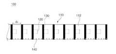
도 1은 본 발명의 일 실시예에 따른 제품식별 라벨 용지의 사시도이다.
도 2는 도 1의 제품식별 라벨 용지의 상면 부분을 나타내는 평면도이다.
도 3은 도 1의 제품식별 라벨 용지의 하면 부분을 나타내는 저면도이다.
도 4는 도 2의 A-A'선에 따른 단면도이다.
도 5는 본 발명의 일 실시예에 따른 제품식별 라벨 용지의 제작 방법을 설명하기 위한 순서도이다.
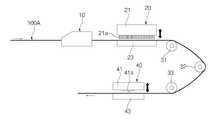
도 6은 도 1의 제품식별 라벨 용지의 제작 방법을 수행하는 개략적인 장치 구성도이다.
도 7 내지 도 11은 본 발명의 일 실시예에 따른 제품식별 라벨 용지의 제작 방법에서 각 단계에 대응하는 제작물을 나타내는 도면들이다1 is a perspective view of a product identification label according to an embodiment of the present invention.
Fig. 2 is a plan view showing a top surface portion of the product identification label sheet of Fig. 1. Fig.
Fig. 3 is a bottom view showing the bottom portion of the product identification label sheet of Fig. 1; Fig.
4 is a cross-sectional view taken along the line A-A 'in Fig.
5 is a flowchart illustrating a method of manufacturing a product identification label sheet according to an embodiment of the present invention.
FIG. 6 is a schematic device configuration diagram for performing the method of manufacturing the product identification label sheet of FIG. 1;
FIGS. 7 to 11 are views showing a product corresponding to each step in the method of manufacturing a product identification label sheet according to an embodiment of the present invention
본 발명과 본 발명의 동작상의 이점 및 본 발명의 실시에 의하여 달성되는 목적을 충분히 이해하기 위해서는 본 발명의 바람직한 실시예를 예시하는 첨부 도면 및 첨부 도면에 기재된 내용을 참조하여야만 한다.In order to fully understand the present invention, operational advantages of the present invention, and objects achieved by the practice of the present invention, reference should be made to the accompanying drawings and the accompanying drawings which illustrate preferred embodiments of the present invention.
이하, 첨부된 도면을 참조하여 본 발명의 바람직한 실시예를 설명함으로써, 본 발명을 상세히 설명한다. 다만, 본 발명을 설명함에 있어서 이미 공지된 기능 혹은 구성에 대한 설명은, 본 발명의 요지를 명료하게 하기 위하여 생략하기로 한다.Hereinafter, the present invention will be described in detail with reference to the preferred embodiments of the present invention with reference to the accompanying drawings. In the following description, well-known functions or constructions are not described in order to avoid unnecessary obscuration of the present invention.
도 1은 본 발명의 일 실시예에 따른 제품식별 라벨 용지의 사시도이고, 도 2는 도 1의 제품식별 라벨 용지의 상면 부분을 나타내는 평면도이고, 도 3은 도 1의 제품식별 라벨 용지의 하면 부분을 나타내는 저면도이며, 도 4는 도 2의 A-A'선에 따른 단면도이다.Fig. 1 is a perspective view of a product identification label sheet according to an embodiment of the present invention, Fig. 2 is a plan view showing an upper surface portion of the product identification label sheet in Fig. 1, Fig. 4 is a cross-sectional view taken along the line A-A 'in Fig. 2. Fig.
도 1 내지 도 4를 참조하면, 본 발명에 따른 제품식별 라벨 용지(100)는 이형지(110), 라벨(120), 광학인식마크(130) 및 피치홀(140)을 포함할 수 있다.1 to 4, the product
이형지(110)는 길이 방향으로 길게 연장되는 스트립 형태로, 일반적으로 폴리에틸렌 테레프탈레이트 필름, 폴리에스테르 필름 또는 종이 등의 재질로 제작된다. 이형지(110)의 상면(111)에는 라벨(120)이 접착되는데, 라벨(120)이 잘 접착되고 잘 떼어질 수 있도록 매끄러운 이형 코팅층(미도시)이 형성된다. 이때, 이형 코팅층은 일반적으로 실리콘 또는 왁스 이형제로 코팅 제공된다.The releasing
라벨(120)은 제품식별코드(예컨대, 제품을 식별하기 위한 QR코드나 바코드 등)가 인쇄되는 영역을 제공한다. 라벨(120)은 그 하면에 접착층(미도시)이 형성되어 이형지(110)의 상면(111)에 접착되어 있다. 라벨(120)은 이형지(110)의 길이 방향을 따라 미리 정해진 간격(d1)을 두고 복수 개가 배치된다. 첨부된 도면들에서 라벨(120)은 대략 정사각형 형상으로 도시되어 있으나, 이는 예시적인 것에 불과하고 본 발명은 이에 한정되지 아니한다.The
광학인식마크(130)는 제품식별 라벨 용지(100)에 대해 라벨(120)에 제품식별코드를 인쇄하는 공정에서 제품식별 라벨 용지(100)의 위치 결정을 위해 제공된다. 일반적으로, 라벨(120)에 제품식별코드를 인쇄하기 위한 연속적인 자동화 인쇄 시스템에서 제품식별 라벨 용지(100)는 일 방향으로 연속적으로 이송 공급되다가 라벨(120)이 인쇄 시스템의 프린터 헤드와 만나는 위치에서 정지하여 프린터 헤드에 의해 라벨(120) 상에 제품식별코드가 인쇄되는데, 이때 제품식별 라벨 용지(100)는 인쇄 시스템에 구비된 광학 센서에 의해 인식 혹은 감지 가능한 광학인식마크(130)를 통해 그 위치가 결정되므로, 라벨(120)이 인쇄 시스템의 프린터 헤드에 대응하는 위치에서 정확히 멈출 수 있다.The
이를 위해, 광학인식마크(130)는 도 1 내지 도 3에 도시된 바와 같이 이형지(110)에 인쇄되되 이형지(110)의 길이 방향을 따라 미리 정해진 간격(d2)을 두고 복수 개가 배치된다. 광학인식마크(130)는 이형지(110)의 폭 방향으로 연장되도록 이형지(110)의 하면(112)에 인쇄된다. 즉, 광학인식마크(130)는 띠 모양으로 이형지(110)의 하면(112)에 인쇄된다. 통상 광학인식마크(130)는 광학 센서에 의해 감지 가능한 물질이 포함된 검은색 잉크를 이형지(110)의 하면(112)에 인쇄하는 것에 의해 제공된다. 이때, 라벨(120)에 제품식별코드를 인쇄하는 공정에서 제품식별 라벨 용지(100)에 대한 위치 결정을 정확하고 정밀하게 하기 위한 측면에서, 광학인식마크(130)의 미리 정해진 간격(d2)은 라벨(120)의 미리 정해진 간격(d1)과 실질적으로 동일하게 설정된다. 즉, 서로 이웃하는 2개 광학인식마크(130) 사이의 간격(d2)과 서로 이웃하는 2개의 라벨(120) 사이의 간격(d1)은 실질적으로 서로 동일하다. 더 나아가, 광학인식마크(130)와의 위치 관계에 있어서 라벨(120)은 도 2 및 도 3에 도시된 바와 같이 그 선단선이 광학인식마크(130)의 후단선과 일치하도록 배치되거나, 이와 반대로 그 후단선이 광학인식마크(130)의 선단선과 일치하도록 배치되는 것이 바람직하다. 여기서 '선단' 및 '후단'의 의미는 라벨(120)에 제품식별코드를 인쇄하는 공정에서 제품식별 라벨 용지(100)의 이송 방향을 기준으로 한다.To this end, the
위와 같은 광학인식마크(130)의 구성에 의해, 본 발명은 라벨(120)에 제품식별코드를 인쇄하는 공정에 대한 자동화 시스템을 원활하게 구현하고 운용할 수 있다.With the above-described configuration of the
피치홀(140)은 제품식별 라벨 용지(100)에 대해 라벨(120)을 이형지(110)로부터 떼어내는 공정에서 제품식별 라벨 용지(100)의 정밀한 이송을 위해 제공된다. 이를 위해, 피치홀(140)은 이형지(110)의 일측에 관통 형성되되 이형지(110)의 길이 방향을 따라 미리 정해진 간격을 두고 복수 개가 배치된다. 이러한 피치홀(140) 구성에 의해 제품식별 라벨 용지(100)는 피치 단위, 즉 피치홀(140)의 미리 정해진 간격 단위로 이송되기 때문에 정밀한 이송이 가능해진다. 참고로, 첨부된 도면들에서 피치홀(140)은 이형지(110)의 일측에만 관통 형성되나, 이와 다르게 피치홀(140)은 이형지(110)의 양측에 각각 관통 형성될 수도 있다.The
일반적으로, 제품식별 라벨 용지(100)에 대해 라벨(120)에 제품식별코드를 인쇄하는 공정이 완료되면, 연속적인 자동화 시스템으로 인쇄된 라벨(120)을 픽업 노즐(Pick Up Nozzle) 등을 사용하여 이형지(110)로부터 떼어내어 제품(예컨대, 휴대폰)의 인쇄회로기판(Printed Circuit Board) 등에 부착하는 공정이 수행된다. 이때, 라벨(120)을 이형지(110)로부터 떼어내고 이를 제품의 인쇄회로기판 등에 부착하는 공정에서 이형지(110)의 일측에 관통 형성된 복수 개의 피치홀(140)을 사용하면, 예컨대 피치홀(140)에 대응되는 이송 핀이 원주 방향을 따라 구비된 회전 기어(미도시)를 사용하여 제품식별 라벨 용지(100)를 이송시키면, 제품식별 라벨 용지(100)가 정밀하게 이송되므로, 이러한 피치홀(140)의 구성에 의해 본 발명은 인쇄된 라벨(120)을 이형지(110)로부터 떼어내어 이를 제품에 부착하는 공정에 대한 자동화 시스템을 원활하게 구현하고 운용할 수 있다.In general, when the process of printing the product identification code on the
도 5는 본 발명의 일 실시예에 따른 제품식별 라벨 용지의 제작 방법을 설명하기 위한 순서도이고, 도 6은 도 1의 제품식별 라벨 용지의 제작 방법을 수행하는 개략적인 장치 구성도이다. 또한, 도 7 내지 도 11은 본 발명의 일 실시예에 따른 제품식별 라벨 용지의 제작 방법에서 각 단계에 대응하는 제작물을 나타내는 도면들이다.FIG. 5 is a flowchart illustrating a method of manufacturing a product identification label sheet according to an embodiment of the present invention, and FIG. 6 is a schematic device configuration diagram illustrating a method of manufacturing the product identification label sheet of FIG. 7 to 11 are views showing a product corresponding to each step in the method of manufacturing a product identification label sheet according to an embodiment of the present invention.
도 5를 참조하면, 본 발명에 따른 제품식별 라벨 용지의 제작 방법은, 원단지를 제공하는 단계(S110), 광학인식마크를 인쇄하는 단계(S120), 피치홀을 형성하는 단계(S130) 및 라벨 영역을 커팅하는 단계(140)를 포함할 수 있다.Referring to FIG. 5, a method of manufacturing a product identification label sheet according to the present invention includes a step S110 of providing an original, a step S120 of printing an optical recognition mark, a step S130 of forming a pitch hole, And cutting 140 the label area.
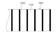
원단지를 제공하는 단계(S110)에서는, 도 7 및 도 8에 도시된 바와 같이 원단지(100A)는 길이 방향으로 길게 연장되되 원단 이형지(110A)의 상면에 원단 라벨지(120A)가 원단 이형지(110A)와 대응하는 면적으로 접착된 구조로 제공된다. 이때, 원단지(100A)는 도 6에 도시된 바와 같이 연속적인 라인으로 공급되어 광학인식마크 인쇄기(10), 피치홀 펀칭기(20), 라벨 영역 커팅기(40)에 의한 공정이 순차적으로 진행된다. 한편, 본 실시예에서 원단지(100A)는 첨부된 도면들을 통해 알 수 있듯이 생산성을 향상시키는 측면에서 2개의 제품식별 라벨 용지(100)를 동시에 제작하기 위한 크기로 제공된다. 다만, 이와 다르게, 원단지(100A)는 1개의 제품식별 라벨 용지(100)에 대응하는 크기 또는 3개 이상의 제품식별 라벨 용지(100)에 대응하는 크기로 제공될 수 있다.7 and 8, the original 100A is elongated in the lengthwise direction, and the
광학인식마크를 인쇄하는 단계(S120)에서는, 도 8에 도시된 바와 같이 원단지(100A)의 하면, 즉 원단 이형지(110A) 부분에 띠 모양의 광학인식마크(130A)가 원단지(100A)의 길이 방향을 따라 미리 정해진 간격으로 복수 개 인쇄된다. 이때, 광학인식마크를 인쇄하는 단계(S120)는 도 6에 도시된 바와 같은 광학인식마크 인쇄기(10)에 의해 수행된다.In step S120 of printing the optical recognition mark, as shown in Fig. 8, the band-shaped
피치홀을 형성하는 단계(S130)에서는 도 9에 도시된 봐와 같이 원단지(100A)의 양측 각각에 피치홀(140A)이 원단지(100A)의 길이 방향을 따라 미리 정해진 간격으로 복수 개 관통 형성된다. 이때, 피치홀을 형성하는 단계(S130)는 도 6에 도시된 바와 같은 피치홀 펀칭기(20)에 의한 펀칭 프레스 작업을 통해 수행되는데, 피치홀 펀칭기(20)는 복수 개의 펀칭 핀(21a)이 구비된 상부 금형(21)과 공급되는 원단지(100A)를 지지하는 하부 금형(23)을 포함하여 구성될 수 있다. 참고로, S130 단계에서 원단지(100A)의 일측만이 아니라 양측에 2개의 열로 피치홀(140A)을 형성하는 것은, 전술한 바와 같이 2개의 제품식별 라벨 용지(100)를 동시에 제작하기 위함이다. 한편, 피치홀 펀칭기(20)를 통과한 원단지(100A)는 도 6에 도시된 바와 같이 다수의 권취롤러(31,32,33)에 의해 그 상면과 하면이 전환된 상태에서 다음 공정을 수행하는 라벨 영역 커팅기(40)로 공급된다.9, pitch holes 140A are formed on both sides of the
라벨 영역을 커팅하는 단계(S140)에서는, 도 7 및 도 10에 도시된 바와 같이 원단지(100A)의 상면, 즉 원단 라벨지(120A) 대해 복수 개의 라벨 영역(120) 혹은 라벨(120)이 커팅된다. 라벨 영역(120)은 원단지(100A)의 길이 방향을 따라 미리 정해진 간격으로 복수 개가 배치되도록 커팅된다. 이때, 라벨 영역을 커팅하는 단계(S140)는 도 6에 도시된 바와 같은 라벨 영역 커팅기(40)에 의한 커팅 프레스 작업을 통해 수행되는데, 라벨 영역 커팅기(40)는 커팅 블레이드(41a)가 구비된 상부 금형(41)과 공급되는 원단지(100A)를 지지하는 하부 금형(43)을 포함하여 구성될 수 있다. 이때, 커팅 블레이드(41a)는 복수 개의 라벨 영역(120)에 대응하는 형상으로 제공되고, 원단 이형지(110A)는 건드리지 않고 원단 라벨지(120A)만을 커팅하는 깊이로 작동하도록 설정된다. 한편, 전술한 바와 같이 2개의 제품식별 라벨 용지(100)를 동시에 제작하는 측면에서 라벨 영역(120)은 원단지(100A)의 길이 방향을 따라 2개의 열로 커팅된다.In step S140 of cutting the label area, a plurality of
라벨 영역(120)이 커팅된 후, 원단 라벨지(120A)에서 라벨 영역(120)을 제외한 부분은 원단 이형지(110A)로부터 떼어내어져 도 10에 도시된 것과 같은 형태를 이루는데, 이를 중앙 절단선(C)을 따라 절단하면 최종적으로 도 11에 도시된 바와 같은 2개의 제품식별 라벨 용지(100)가 완성된다.After the
한편, 이상 설명한 본 실시예에서는, 원단지(100A)가 연속적인 라인으로 광학인식마크 인쇄기(10), 피치홀 펀칭기(20) 및 라벨 영역 커팅기(40)에 순차적으로 공급되어 광학인식마크 인쇄 단계(S120), 피치홀 형성 단계(S130) 및 라벨 영역 커팅 단계(S140)가 순차적으로 수행되고 있지만, 본 발명은 이에 한정되지 아니하고, 이들 단계의 진행 순서는 경우에 따라 적절히 변경될 수 있다. 예컨대, 광학인식마크 인쇄 단계(S120)에 앞서 피치홀 형성 단계(S130)가 수행될 수도 있으며, 광학인식마크 인쇄 단계(S120) 이전에 라벨 영역 커팅 단계(S140)가 수행될 수도 있다. 더 나아가, 원단지(100A)는 모든 단계에 대해 하나의 연속적인 라인으로 공급되지 아니하고, 각 단계에 따라 독립적인 라인으로 공급될 수도 있다.On the other hand, in the embodiment described above, the original 100A is sequentially supplied to the optical
본 발명은 전술한 실시예들에 한정되는 것이 아니고, 본 발명의 사상 및 범위를 벗어나지 않고 다양하게 수정 및 변형할 수 있음은 이 기술의 분야에서 통상의 지식을 가진 자에게 자명하다. 따라서 그러한 수정예 또는 변형예들은 본 발명의 특허청구범위에 속한다 하여야 할 것이다.It will be apparent to those skilled in the art that various modifications and variations can be made in the present invention without departing from the spirit and scope of the invention. Accordingly, such modifications or variations are intended to fall within the scope of the appended claims.
100 : 제품식별 라벨 용지
110 : 이형지
120 : 라벨
130 : 광학인식마크
140 : 피치홀
100A : 원단지
110A : 원단 이형지
120A : 원단 라벨지
10 : 광학인식마크 인쇄기
20 : 피치홀 펀칭기
40 : 라벨 영역 커팅기100: Product identification label paper
110: release paper
120: Label
130: Optical recognition mark
140: pitch hole
100A: one circle
110A: fabric release sheet
120A: Fabric label paper
10: Optical recognition mark printing machine
20: Pitch hole punching machine
40: Label area cutter
Claims (10)
Translated fromKorean길이 방향으로 연장되는 이형지;
제품식별코드가 인쇄되는 영역을 제공하는 것으로 상기 이형지의 상면에 접착되되 상기 이형지의 길이 방향을 따라 미리 정해진 간격을 두고 배치되는 복수 개의 라벨;
상기 이형지에 인쇄되되 상기 이형지의 길이 방향을 따라 미리 정해진 간격을 두고 배치되는 복수 개의 광학인식마크; 및
상기 이형지의 일측에 관통 형성되되 상기 이형지의 길이 방향을 따라 미리 정해진 간격을 두고 배치되는 복수 개의 피치홀을 포함하고,
상기 복수 개의 라벨은,
상기 광학인식마크와의 위치 관계에 있어서, 상기 라벨에 제품식별코드를 인쇄하는 공정에서 상기 제품식별 라벨 용지의 이송 방향을 기준으로, 상기 라벨의 선단선이 상기 광학인식마크의 후단선과 일치하도록 배치되고, 상기 라벨의 후단선이 상기 광학인식마크의 선단선과 일치하도록 배치되며,
상기 광학인식마크는,
상기 라벨에 제품식별코드를 인쇄하는 공정에서, 상기 라벨에 상기 제품식별코드를 인쇄하기 위한 연속적인 자동화 인쇄 시스템에 의해 일 방향으로 연속적으로 이송 공급되다가 상기 자동화 인쇄 시스템에 구비된 광학 센서에 의해 인식 또는 감지되고, 상기 광학 센서에 의해 인식 또는 감지된 위치를 기초로 하여 상기 제품식별 라벨 용지의 위치를 결정하고,
상기 피치홀은,
상기 라벨을 상기 이형지로부터 떼어내어 제품에 부착하는 공정에서 상기 제품식별 라벨 용지의 정밀한 이송을 위해 제공되는 것을 특징으로 하는 제품식별 라벨 용지.
For product identification label paper,
A release paper extending in the longitudinal direction;
A plurality of labels adhered to an upper surface of the release paper, the label being provided at a predetermined interval along a longitudinal direction of the release paper to provide an area where a product identification code is printed;
A plurality of optical recognition marks printed on the release paper, the plurality of optical recognition marks being arranged at predetermined intervals along the longitudinal direction of the release paper; And
And a plurality of pitch holes formed at one side of the release paper and arranged at predetermined intervals along the longitudinal direction of the release paper,
The plurality of labels may include:
In the positional relationship with the optical recognition mark, in the step of printing the product identification code on the label, the line break of the label is aligned with the trailing line of the optical identification mark on the basis of the transfer direction of the product identification label sheet And the rear end of the label is arranged to coincide with the front end of the optical recognition mark,
Wherein the optical recognition mark comprises:
Wherein the product identification code is continuously fed in one direction by a continuous automatic printing system for printing the product identification code on the label in the step of printing the product identification code on the label, Determining the position of the product identification label sheet based on the position sensed or sensed by the optical sensor,
The pitch hole
Characterized in that the label is provided for precise transfer of the product identification label paper in a process of removing the label from the release paper and attaching it to the product.
상기 광학인식마크의 미리 정해진 간격은,
상기 라벨의 미리 정해진 간격과 실질적으로 동일하게 설정되는 것을 특징으로 하는 제품식별 라벨 용지.
The method according to claim 1,
The predetermined interval of the optical recognition mark may be,
Is set to be substantially equal to a predetermined interval of the label.
상기 광학인식마크는,
상기 이형지의 폭 방향으로 연장되도록 상기 이형지의 하면에 인쇄되는 것을 특징으로 하는 제품식별 라벨 용지.
The method according to claim 1,
Wherein the optical recognition mark comprises:
And the label is printed on the lower surface of the release paper so as to extend in the width direction of the release paper.
Priority Applications (1)
| Application Number | Priority Date | Filing Date | Title |
|---|---|---|---|
| KR20130083738AKR101470351B1 (en) | 2013-07-16 | 2013-07-16 | Product identification label sheet and manufacturing method for the same |
Applications Claiming Priority (1)
| Application Number | Priority Date | Filing Date | Title |
|---|---|---|---|
| KR20130083738AKR101470351B1 (en) | 2013-07-16 | 2013-07-16 | Product identification label sheet and manufacturing method for the same |
Publications (1)
| Publication Number | Publication Date |
|---|---|
| KR101470351B1true KR101470351B1 (en) | 2014-12-08 |
Family
ID=52678091
Family Applications (1)
| Application Number | Title | Priority Date | Filing Date |
|---|---|---|---|
| KR20130083738AActiveKR101470351B1 (en) | 2013-07-16 | 2013-07-16 | Product identification label sheet and manufacturing method for the same |
Country Status (1)
| Country | Link |
|---|---|
| KR (1) | KR101470351B1 (en) |
Cited By (2)
| Publication number | Priority date | Publication date | Assignee | Title |
|---|---|---|---|---|
| KR101508186B1 (en)* | 2014-12-16 | 2015-04-07 | 이경구 | the printer for label paper |
| WO2017195970A1 (en)* | 2016-05-12 | 2017-11-16 | 주식회사 유성소프트 | Care-label having rfid tag and production method therefor |
Citations (2)
| Publication number | Priority date | Publication date | Assignee | Title |
|---|---|---|---|---|
| JPH06289787A (en)* | 1993-03-31 | 1994-10-18 | Toppan Moore Co Ltd | Label sheet |
| JP2005164925A (en)* | 2003-12-02 | 2005-06-23 | Seiko Epson Corp | RECORDING MEDIUM FOR LABEL CREATION, LABEL CREATION METHOD AND LABEL CREATION SYSTEM |
- 2013
- 2013-07-16KRKR20130083738Apatent/KR101470351B1/enactiveActive
Patent Citations (2)
| Publication number | Priority date | Publication date | Assignee | Title |
|---|---|---|---|---|
| JPH06289787A (en)* | 1993-03-31 | 1994-10-18 | Toppan Moore Co Ltd | Label sheet |
| JP2005164925A (en)* | 2003-12-02 | 2005-06-23 | Seiko Epson Corp | RECORDING MEDIUM FOR LABEL CREATION, LABEL CREATION METHOD AND LABEL CREATION SYSTEM |
Cited By (2)
| Publication number | Priority date | Publication date | Assignee | Title |
|---|---|---|---|---|
| KR101508186B1 (en)* | 2014-12-16 | 2015-04-07 | 이경구 | the printer for label paper |
| WO2017195970A1 (en)* | 2016-05-12 | 2017-11-16 | 주식회사 유성소프트 | Care-label having rfid tag and production method therefor |
Similar Documents
| Publication | Publication Date | Title |
|---|---|---|
| US8488134B2 (en) | Multifunction device for prefabricating marking labels | |
| US8360124B2 (en) | Apparatus and process for in-mold labeling | |
| EP3093797A1 (en) | Reading and writing verification device for rfid medium, and reading and writing verification method for same | |
| US20080295318A1 (en) | Method and Device for Continuously Producing Electronic Film Components and an Electronic Film Component | |
| KR101597365B1 (en) | Method and device for producing an rfid label | |
| KR101470351B1 (en) | Product identification label sheet and manufacturing method for the same | |
| KR20090059575A (en) | Method for manufacturing label sticker, label molding die used therein, and label sticker thereby | |
| JP2010120234A (en) | Mountless continuous label object and production method for mountless continuous label object | |
| EP2221794B1 (en) | Label sheet producing device | |
| EP3021307B1 (en) | Label provided with indentations | |
| JP4779556B2 (en) | Method and apparatus for manufacturing conductive member for non-contact type data carrier | |
| JP5510819B2 (en) | Label sheet processing apparatus and processing method | |
| JP2011095616A (en) | Rfid label continuous body, method of manufacturing the same, and method of using the same | |
| CN104680224A (en) | RFID chip-implanted label sticker and preparation method thereof | |
| JP4750569B2 (en) | Label continuum | |
| US20220194070A1 (en) | Sheet processing system and method | |
| US6972067B1 (en) | System and method for automated placement of pre-printed sheets onto a web | |
| US8640325B2 (en) | Method of continuously producing electronic film components | |
| JP6744883B2 (en) | RFID medium read/write verification device and read/write verification method thereof | |
| TWI666292B (en) | Pressure-sensitive adhesive sheet and method of manufacturing pressure-sensitive adhesive sheet | |
| JP5893255B2 (en) | Manufacturing method of micro label | |
| CN110853953B (en) | Low-cost dome module processing method | |
| JP2004066431A (en) | Label processing machine | |
| EP4407512A1 (en) | Rfid container and production method for rfid container | |
| JP2017182717A (en) | Rfid recording medium sheet manufacturing method and card |
Legal Events
| Date | Code | Title | Description |
|---|---|---|---|
| PA0109 | Patent application | Patent event code:PA01091R01D Comment text:Patent Application Patent event date:20130716 | |
| PA0201 | Request for examination | ||
| PE0902 | Notice of grounds for rejection | Comment text:Notification of reason for refusal Patent event date:20140623 Patent event code:PE09021S01D | |
| PE0701 | Decision of registration | Patent event code:PE07011S01D Comment text:Decision to Grant Registration Patent event date:20140926 | |
| GRNT | Written decision to grant | ||
| PR0701 | Registration of establishment | Comment text:Registration of Establishment Patent event date:20141202 Patent event code:PR07011E01D | |
| PR1002 | Payment of registration fee | Payment date:20141203 End annual number:3 Start annual number:1 | |
| PG1601 | Publication of registration | ||
| FPAY | Annual fee payment | Payment date:20171025 Year of fee payment:4 | |
| PR1001 | Payment of annual fee | Payment date:20171025 Start annual number:4 End annual number:4 | |
| FPAY | Annual fee payment | Payment date:20181002 Year of fee payment:5 | |
| PR1001 | Payment of annual fee | Payment date:20181002 Start annual number:5 End annual number:5 | |
| FPAY | Annual fee payment | Payment date:20190924 Year of fee payment:6 | |
| PR1001 | Payment of annual fee | Payment date:20190924 Start annual number:6 End annual number:6 | |
| PR1001 | Payment of annual fee | Payment date:20200924 Start annual number:7 End annual number:7 | |
| PR1001 | Payment of annual fee | Payment date:20210927 Start annual number:8 End annual number:8 | |
| PR1001 | Payment of annual fee | Payment date:20220927 Start annual number:9 End annual number:9 | |
| PR1001 | Payment of annual fee | Payment date:20230925 Start annual number:10 End annual number:10 | |
| PR1001 | Payment of annual fee | Payment date:20241111 Start annual number:11 End annual number:11 |