KR101469628B1 - Walking supporter - Google Patents
Walking supporterDownload PDFInfo
- Publication number
- KR101469628B1 KR101469628B1KR1020140081627AKR20140081627AKR101469628B1KR 101469628 B1KR101469628 B1KR 101469628B1KR 1020140081627 AKR1020140081627 AKR 1020140081627AKR 20140081627 AKR20140081627 AKR 20140081627AKR 101469628 B1KR101469628 B1KR 101469628B1
- Authority
- KR
- South Korea
- Prior art keywords
- support
- auxiliary leg
- lower support
- auxiliary
- leg
- Prior art date
- Legal status (The legal status is an assumption and is not a legal conclusion. Google has not performed a legal analysis and makes no representation as to the accuracy of the status listed.)
- Expired - Fee Related
Links
Images


Classifications
- A—HUMAN NECESSITIES
- A61—MEDICAL OR VETERINARY SCIENCE; HYGIENE
- A61H—PHYSICAL THERAPY APPARATUS, e.g. DEVICES FOR LOCATING OR STIMULATING REFLEX POINTS IN THE BODY; ARTIFICIAL RESPIRATION; MASSAGE; BATHING DEVICES FOR SPECIAL THERAPEUTIC OR HYGIENIC PURPOSES OR SPECIFIC PARTS OF THE BODY
- A61H3/00—Appliances for aiding patients or disabled persons to walk about
- A61H3/008—Appliances for aiding patients or disabled persons to walk about using suspension devices for supporting the body in an upright walking or standing position, e.g. harnesses
- A—HUMAN NECESSITIES
- A61—MEDICAL OR VETERINARY SCIENCE; HYGIENE
- A61H—PHYSICAL THERAPY APPARATUS, e.g. DEVICES FOR LOCATING OR STIMULATING REFLEX POINTS IN THE BODY; ARTIFICIAL RESPIRATION; MASSAGE; BATHING DEVICES FOR SPECIAL THERAPEUTIC OR HYGIENIC PURPOSES OR SPECIFIC PARTS OF THE BODY
- A61H3/00—Appliances for aiding patients or disabled persons to walk about
- A61H2003/007—Appliances for aiding patients or disabled persons to walk about secured to the patient, e.g. with belts
- A—HUMAN NECESSITIES
- A61—MEDICAL OR VETERINARY SCIENCE; HYGIENE
- A61H—PHYSICAL THERAPY APPARATUS, e.g. DEVICES FOR LOCATING OR STIMULATING REFLEX POINTS IN THE BODY; ARTIFICIAL RESPIRATION; MASSAGE; BATHING DEVICES FOR SPECIAL THERAPEUTIC OR HYGIENIC PURPOSES OR SPECIFIC PARTS OF THE BODY
- A61H2201/00—Characteristics of apparatus not provided for in the preceding codes
- A61H2201/16—Physical interface with patient
- A61H2201/1602—Physical interface with patient kind of interface, e.g. head rest, knee support or lumbar support
- A61H2201/164—Feet or leg, e.g. pedal
- A61H2201/1642—Holding means therefor
- A—HUMAN NECESSITIES
- A61—MEDICAL OR VETERINARY SCIENCE; HYGIENE
- A61H—PHYSICAL THERAPY APPARATUS, e.g. DEVICES FOR LOCATING OR STIMULATING REFLEX POINTS IN THE BODY; ARTIFICIAL RESPIRATION; MASSAGE; BATHING DEVICES FOR SPECIAL THERAPEUTIC OR HYGIENIC PURPOSES OR SPECIFIC PARTS OF THE BODY
- A61H2201/00—Characteristics of apparatus not provided for in the preceding codes
- A61H2201/16—Physical interface with patient
- A61H2201/1602—Physical interface with patient kind of interface, e.g. head rest, knee support or lumbar support
- A61H2201/165—Wearable interfaces
- A—HUMAN NECESSITIES
- A61—MEDICAL OR VETERINARY SCIENCE; HYGIENE
- A61H—PHYSICAL THERAPY APPARATUS, e.g. DEVICES FOR LOCATING OR STIMULATING REFLEX POINTS IN THE BODY; ARTIFICIAL RESPIRATION; MASSAGE; BATHING DEVICES FOR SPECIAL THERAPEUTIC OR HYGIENIC PURPOSES OR SPECIFIC PARTS OF THE BODY
- A61H2205/00—Devices for specific parts of the body
- A61H2205/10—Leg
- A61H2205/102—Knee
Landscapes
- Health & Medical Sciences (AREA)
- Epidemiology (AREA)
- Pain & Pain Management (AREA)
- Physical Education & Sports Medicine (AREA)
- Rehabilitation Therapy (AREA)
- Life Sciences & Earth Sciences (AREA)
- Animal Behavior & Ethology (AREA)
- General Health & Medical Sciences (AREA)
- Public Health (AREA)
- Veterinary Medicine (AREA)
- Rehabilitation Tools (AREA)
- Orthopedics, Nursing, And Contraception (AREA)
Abstract
Translated fromKoreanDescription
Translated fromKorean본 발명은 보행 보조기에 관한 것으로, 더욱 상세하게는 보행시 보조기구의 사용이 요구될 때 다리에 착용되는 보행 보조기에 관한 것이다.The present invention relates to a walking aid, and more particularly, to a walking aid that is worn on a leg when the use of an assistant in walking is required.
근력이 약한 노약자나 근력이 저하된 환자 또는 장애인들은 별도의 보행 보조기 없이는 보행이 힘들며, 주변 환경에 대한 신속한 대처가 어렵다.The elderly with weak muscles, those with weak muscles or those with disabilities are unable to walk without a separate walking aids, and it is difficult to quickly cope with the surrounding environment.
일반적인 보행 보조기로는 손으로 붙잡고 보행하는데 사용되는 지팡이나, 일정 높이의 프레임 상단부에 손잡이가 구비되고 하단부에 바퀴가 장착된 보행 훈련기, 그리고 근력이 약화된 관절 부위에 장착하는 관절 보조기 등이 있다.Typical walking aids include a walking stick that is used to hold and walk, a walking trainer with a handle at the top of the frame at a certain height, a wheel at the lower end, and an articulation aid that attaches to the weakened muscle.
그런데, 지팡이나 보행 훈련기는 일어선 상태에서 상체의 힘으로 보행을 보조하는 것일 뿐이어서 실질적으로 보행을 돕는데 한계가 있고, 사용자의 상체 근력을 이용하여 보행을 보조하기 때문에 체력의 소모가 커서 단거리 이동에도 많은 에너지를 필요로 한다.However, since the cane or the walking trainer assists the walking with the force of the upper body in the state of being engaged, there is a limit in practically supporting the walking, and since the walking is assisted by using the upper body strength of the user, Also requires a lot of energy.
또한, 관절 보조기의 경우, 관절 보조기를 착용한 환자나 장애인, 노약자들은 다리 힘이 약하여 보행중 균형을 잃고 뒤로 넘어질 때가 많은데, 종래의 관절 보조기에는 이에 대한 아무런 대비가 없다.In addition, in the case of an articulated orbital prosthesis, patients wearing an orthosis, a person with a disability, or an elderly person often have a weak leg so that they lose balance during a walk and fall backward.
특히 이들이 계단을 내려올 때에는, 계단을 밟는 한쪽 다리에 순간적으로 강한 부하가 걸리므로, 사고 예방을 위해서는 발바닥 전체가 계단을 확실히 딛도록 하는 한편, 발바닥에 걸리는 부하를 분산시킬 필요가 있다.Particularly when they descend the stairs, since a strong load instantly takes on one leg that steps on the stairs, in order to prevent an accident, it is necessary to make sure that the whole of the sole is completely stepped and the load applied to the sole is dispersed.
본 발명은 전술한 문제점을 해결하기 위하여 안출된 것으로서, 사용자가 뒤로 넘어지지 않도록 보조다리를 구비한 보행 보조기를 제공함에 목적이 있다.SUMMARY OF THE INVENTION It is an object of the present invention to provide a walking aid provided with auxiliary legs to prevent a user from falling back.
본 발명의 다른 목적은 보행시 충격을 흡수할 수 있는 보행 보조기를 제공함에 있다.Another object of the present invention is to provide a walking aids capable of absorbing an impact when walking.
본 발명의 또 다른 목적은 계단을 내려올 때 발을 딛는 위치를 안내함으로써 사고를 예방할 수 있는 보행 보조기를 제공함에 있다.It is still another object of the present invention to provide a walking aid that can prevent an accident by guiding a foot position when descending a stairway.
본 발명의 또 다른 목적은 보조다리의 길이가 조절되는 보행 보조기를 제공함에 있다.It is still another object of the present invention to provide a walking aid in which the length of the auxiliary legs is adjusted.
본 발명의 또 다른 목적은 보조다리의 회전 각도를 조절할 수 있는 보행 보조기를 제공함에 있다.It is still another object of the present invention to provide a walking aid capable of adjusting the rotation angle of the auxiliary leg.
전술한 본 발명의 목적은, 대퇴부의 일측을 감싸서 지지하며, 좌우 양단에서 제1 결합부가 하향 연장 형성되는 상부지지대; 종아리부의 일측을 감싸서 지지하며, 좌우 양단에서 제2 결합부가 상향 연장 형성되어 상기 제1 결합부와 힌지결합하는 하부지지대; 및 상기 하부지지대의 후방에 일단이 고정되고, 타단이 하향 연장되어 지면에 지지되는 보조다리를 포함하며, 상기 보조다리는 상기 하부지지대의 후방에 일단이 결합되고 타단이 지면 방향으로 연장되며 길이 조절이 가능한 연장부와, 상기 연장부의 하단에 형성되는 지지부를 포함하되, 상기 지지부는 플레이트 형상으로서 지면에 안정적으로 지지되는 것을 특징으로 하는 보행 보조기를 제공함에 의해 달성될 수 있다.The above-described object of the present invention is achieved by an upper support which supports one side of a thigh portion and supports the first engagement portion downward at both left and right ends thereof; A lower support which surrounds and supports one side of the calf portion and is hinged to the first engagement portion by extending the second engagement portion upward at both the left and right ends; And an auxiliary leg having one end fixed to the rear of the lower support and the other end extended downward and supported on the ground, the auxiliary leg having one end coupled to the rear of the lower support and the other end extending in the direction of the ground, And a support portion formed at a lower end of the extension portion, wherein the support portion is in the form of a plate and is stably supported on the ground.
본 발명의 바람직한 특징에 의하면, 상기 하부지지대의 둘레를 따라 상기 보조다리가 복수 개 구비될 수 있다.According to a preferred aspect of the present invention, a plurality of auxiliary legs may be provided along the periphery of the lower support.
삭제delete
본 발명의 또 다른 바람직한 특징에 의하면, 상기 연장부는, 상기 하부지지대의 후방에 결합되어 하향 절곡되는 절곡부재와, 상기 절곡부재의 중공에 삽입되어 길이가 조절되는 높이조절부재를 포함할 수 있다.According to another preferred aspect of the present invention, the extending portion may include a folding member coupled to the rear of the lower support and bent downward, and a height adjusting member inserted into the hollow of the folding member to adjust its length.
삭제delete
본 발명의 또 다른 바람직한 특징에 의하면, 상기 지지부의 상측에 상기 연장부의 하단이 삽입 결합되는 삽입부가 돌출 형성될 수 있다.According to another preferred aspect of the present invention, an inserting portion into which the lower end of the extending portion is inserted can be formed on the upper side of the supporting portion.
본 발명의 또 다른 바람직한 특징에 의하면, 상기 지지부는 편자 형태이며, 상기 지지부의 양단이 상기 연장부의 후방으로 연장 형성될 수 있다.According to another preferred feature of the present invention, the supporting portion is in the form of a horseshoe, and both ends of the supporting portion may be formed to extend rearward of the extending portion.
본 발명의 또 다른 바람직한 특징에 의하면, 상기 지지부의 하단에 탄성재질의 충격흡수부재가 구비될 수 있다.According to another preferred aspect of the present invention, an elastic shock absorbing member may be provided at the lower end of the support portion.
본 발명의 또 다른 바람직한 특징에 의하면, 상기 지지부는, 상기 연장부의 하단이 상단에 결합되고 내부에 공간부가 형성되는 몸체와, 상기 공간부의 일측에 구비되는 탄성부재와, 상기 탄성부재에 의해 상기 몸체의 후방으로 탄성 지지되는 돌출부재를 포함할 수 있다.According to another preferred aspect of the present invention, the support portion includes a body having a lower end coupled to an upper end of the extension portion and having a space portion formed therein, an elastic member provided at one side of the space portion, And a protruding member that is elastically supported rearward of the protruding member.
본 발명의 또 다른 바람직한 특징에 의하면, 상기 돌출부재의 단부에 탄성재질의 충격흡수부재가 구비될 수 있다.According to another preferred feature of the present invention, the end of the projecting member may be provided with an impact absorbing member made of an elastic material.
본 발명의 또 다른 바람직한 특징에 의하면, 상기 상부지지대의 좌우 양단부는 전방에서 서로 이격하며, 상기 상부지지대의 좌우 양단에 상기 상부지지대 전방의 이격 공간부를 가로지르는 탄성밴드의 양단이 결합될 수 있다.According to another preferred aspect of the present invention, the left and right ends of the upper support are separated from each other at the front, and both ends of the elastic band crossing the spacing space in front of the upper support are coupled to both ends of the upper support.
한편, 전술한 본 발명의 목적은 종아리부의 일측을 감싸서 지지하는 하부지지대; 및 상기 하부지지대의 후방에 일단이 결합되고, 타단이 하향 연장되어 지면에 지지되는 보조다리를 포함하며, 상기 보조다리는, 상기 하부지지대의 후방에 일단이 결합되고 타단이 지면 방향으로 연장되며 길이 조절이 가능한 연장부와, 상기 연장부의 하단에 형성되는 지지부를 포함하되, 상기 지지부는 플레이트 형상으로서 지면에 안정적으로 지지되는 것을 특징으로 하는 보행 보조기를 제공함에 의해서도 달성될 수 있다.According to another aspect of the present invention, there is provided an apparatus for supporting a calf, comprising: a lower support for supporting and supporting one side of a calf; And a supplementary leg having one end connected to the rear of the lower support and the other end extending downward and supported on the ground, the auxiliary leg having one end coupled to the rear of the lower support and the other end extending in the direction of the ground, And a support portion formed at a lower end of the extension portion, wherein the support portion is in the form of a plate and is stably supported on the ground.
이때, 본 발명의 바람직한 특징에 의하면, 상기 하부지지대의 둘레를 따라 상기 보조다리가 복수 개 구비될 수 있다.At this time, according to a preferred aspect of the present invention, a plurality of auxiliary legs may be provided along the circumference of the lower support.
삭제delete
본 발명의 다른 바람직한 특징에 의하면, 상기 하부지지대의 후방에 보조다리 결합부가 구비되고, 상기 보조다리의 일단이 상기 보조다리 결합부에 회전 가능하게 결합될 수 있다.According to another preferred aspect of the present invention, the auxiliary leg coupling portion is provided at the rear of the lower support, and one end of the auxiliary leg is rotatably coupled to the auxiliary leg coupling portion.
본 발명의 또 다른 바람직한 특징에 의하면, 상기 보조다리의 일단에 회전볼이 형성되고, 상기 보조다리 결합부에는 상기 회전볼이 수용되는 볼 수용홈이 형성될 수 있다.According to another preferred aspect of the present invention, a rotating ball is formed at one end of the auxiliary leg, and a ball receiving groove for receiving the rotating ball may be formed at the auxiliary leg connecting portion.
본 발명의 또 다른 바람직한 특징에 의하면, 상기 보조다리 결합부의 일측을 관통하여 상기 볼 수용홈으로 조절구가 삽입되고, 상기 조절구의 일단에는 가압부가 구비되며, 상기 조절구에 의해 상기 가압부가 상기 회전볼의 일측을 가압하여 고정시킬 수 있다.According to another preferred aspect of the present invention, the control port is inserted into the ball receiving groove through one side of the auxiliary leg engagement portion, and the pressure port is provided at one end of the control port, One side of the ball can be pressed and fixed.
본 발명의 또 다른 바람직한 특징에 의하면, 상기 지지부의 상측에 보조다리 결합부가 구비되고, 상기 연장부가 상기 보조다리 결합부에 회전 가능하게 결합될 수 있다.According to another preferred aspect of the present invention, the auxiliary leg coupling portion is provided on the upper side of the support portion, and the extension portion is rotatably coupled to the auxiliary leg coupling portion.
본 발명의 또 다른 바람직한 특징에 의하면, 상기 연장부의 일단에 회전볼이 형성되고, 상기 보조다리 결합부에는 상기 회전볼이 수용되는 볼 수용홈이 형성될 수 있다.According to another preferred aspect of the present invention, a rotating ball is formed at one end of the extended portion, and a ball receiving groove for receiving the rotating ball may be formed in the auxiliary leg connecting portion.
본 발명의 또 다른 바람직한 특징에 의하면, 상기 연장부의 하단부에 후방으로 소정 각도 꺾인 꺾임부가 형성될 수 있다.According to another preferred aspect of the present invention, a bent portion bent backward at a predetermined angle may be formed at a lower end portion of the extended portion.
본 발명에 따른 보행 보조기에 의하면, 사용자의 다리 뒷부분이 보조다리에 의해 지지되므로, 순간적으로 균형을 잃고 뒤로 넘어지게 되는 사고를 방지할 수 있다.According to the present invention, since the rear leg of the user is supported by the auxiliary leg, it is possible to prevent an accident that the balance is lost momentarily and falls back.
또한, 본 발명에 따른 보행 보조기에 의하면, 지면과 접촉하는 하단부에 충격흡수부재가 구비되므로, 보행시 충격을 흡수하여 무릎관절을 보호할 수 있다.In addition, according to the present invention, since the shock absorbing member is provided at the lower end portion contacting the ground, the knee joint can be protected by absorbing the shock when walking.
또한, 본 발명에 따른 보행 보조기에 의하면, 보조다리를 계단의 단턱에 밀착시킴으로써, 계단을 쉽고 안전하게 내려올 수 있다.In addition, according to the walking aid according to the present invention, the stairs can be easily and safely lowered by bringing the auxiliary leg into close contact with the step of the stairs.
또한, 본 발명에 따른 보행 보조기에 의하면, 사용자의 체격에 맞춰 보조다리의 길이를 조절할 수 있다.In addition, according to the walking aid according to the present invention, the length of the auxiliary leg can be adjusted according to the user's physique.
또한, 본 발명에 따른 보행 보조기에 의하면, 보조다리의 회전 각도를 조절하여 더욱 안정적으로 지면에 지지되게끔 할 수 있다.Further, according to the present invention, it is possible to adjust the rotation angle of the auxiliary leg so as to be more stably supported on the ground.
도 1은 본 발명의 일 실시예에 따른 보행 보조기의 사시도.
도 2는 본 발명의 일 실시예에 따른 상부지지대의 사시도.
도 3은 본 발명의 일 실시예에 따른 하부지지대의 사시도.
도 4는 본 발명의 일 실시예에 따른 지지부의 사시도.
도 5는 본 발명의 다른 실시예에 따른 지지부의 사시도.
도 6은 본 발명의 다른 실시예에 따른 지지부의 단면도.
도 7과 도 8은 본 발명의 일 실시예에 따른 보행 보조기의 사용 상태도.
도 9와 도 10은 본 발명의 또 다른 실시예에 따른 보조다리의 결합 단면도.
도 11과 도 12는 본 발명의 또 다른 실시예에 따른 보행 보조기의 사용 상태도.
도 13은 본 발명의 또 다른 실시예에 따라 꺾임부가 형성된 보행 보조기의 사용 상태도.1 is a perspective view of a walking aid according to an embodiment of the present invention;
2 is a perspective view of an upper support according to one embodiment of the present invention;
3 is a perspective view of a lower support according to an embodiment of the present invention;
4 is a perspective view of a support according to an embodiment of the present invention;
5 is a perspective view of a support according to another embodiment of the present invention;
6 is a cross-sectional view of a support according to another embodiment of the present invention;
FIGS. 7 and 8 are views showing the use state of the walking aids according to an embodiment of the present invention. FIG.
FIG. 9 and FIG. 10 are coupling sectional views of auxiliary legs according to another embodiment of the present invention. FIG.
FIG. 11 and FIG. 12 are views showing the use state of the walking aid according to still another embodiment of the present invention. FIG.
FIG. 13 is a use state view of a walking aid provided with a bent portion according to another embodiment of the present invention. FIG.
이하에서는 본 발명의 실시예에 관하여 첨부도면을 참조하여 상세하게 설명하기로 한다. 다만, 이하에서 설명되는 실시예는 본 발명이 속하는 기술분야에서 통상의 지식을 가진 자가 발명을 쉽게 실시할 수 있을 정도로 상세하게 설명하기 위한 것에 불과하며, 이로 인해 본 발명의 보호범위가 한정되는 것을 의미하지는 않는다. 그리고 본 발명의 여러 실시예를 설명함에 있어서, 동일한 기술적 특징을 갖는 구성요소에 대하여는 동일한 도면부호를 사용하기로 한다.Hereinafter, embodiments of the present invention will be described in detail with reference to the accompanying drawings. It is to be understood, however, that the embodiments described below are only for explanation of the embodiments of the present invention so that those skilled in the art can easily carry out the invention, It does not mean anything. In describing various embodiments of the present invention, the same reference numerals are used for components having the same technical characteristics.
실시예Example
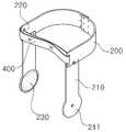
도 1은 본 발명의 일 실시예에 따른 보행 보조기의 사시도이다.1 is a perspective view of a walking aids according to an embodiment of the present invention.
도 1에 도시된 바와 같이, 본 발명의 일 실시예에 따른 보행 보조기(100)는 대퇴부를 지지하는 상부지지대(200)와, 종아리부를 지지하는 하부지지대(300), 및 하부지지대(300)의 후방에서 지면을 향해 연장되는 보조다리(500)를 포함한다.1, a
상부지지대(200)와 하부지지대(300)는 제1 결합부(210) 및 제2 결합부(310)에 의해 힌지 결합하며, 사용자가 무릎을 굽히거나 펼 때 힌지 결합부를 중심으로 서로에 대하여 상대적으로 회전할 수 있다.The
보조다리(500)는 하부지지대(300)의 후방에서 지면에 지지되며, 사용자의 무게중심이 뒤쪽으로 쏠릴 때 넘어가지 않도록 받쳐주는 역할을 하는 한편, 계단을 내려갈 때 발을 딛는 방향을 안내하는 역할을 한다.The
도 2는 본 발명의 일 실시예에 따른 상부지지대의 사시도이다.2 is a perspective view of an upper support according to an embodiment of the present invention.
상부지지대(200)는 탄성과 강도가 우수하면서도 가벼운 가죽이나 플라스틱 또는 카본 소재로 이루어질 수 있으며, 사용자의 대퇴부 후방을 감싸서 지지하게 된다. 이를 위해 상부지지대(200)는 사용자의 대퇴부 골격 및 피부 형상에 대응되도록 소정 폭을 가진 만곡된 띠 형상을 이룰 수 있다.The
이때, 상부지지대(200)는 하나의 부재로 이루어질 수도 있으며, 도 2에 도시된 바와 같이 서로 대칭인 2개의 부재가 볼트 등의 체결구에 의해 결합되어 이루어지는 것도 가능하다. 이 경우, 2개의 부재가 서로 겹쳐져서 결합되는 면적을 조절함으로써 상부지지대(200)의 길이 등 규격을 사용자의 체격에 맞게 조절할 수 있다.At this time, the
상부지지대(200)의 좌우 양단부는 전방에서 양쪽으로 서로 이격하며, 상부지지대 전방의 이격 공간부를 가로지르도록 탄성밴드(400)가 결합된다. 이때, 탄성밴드(400)의 일단은 상부지지대(200)의 일단에 형성되는 제1 결속홈(220)에 결합되고, 탄성밴드(400)의 타단은 상부지지대(200)의 타단에 형성되는 제1 결속홈(220)에 결합된다.The left and right ends of the
따라서, 상부지지대(200) 착용시, 사용자의 대퇴부 전방은 탄성밴드(400)에 의해 지지되고, 대퇴부 후방은 상부지지대(200)에 의해 지지된다. 이때, 탄성밴드(400)의 일측에 길이조절용 고리(미도시)가 구비되는 것도 가능하다. 다른 예로서, 상부지지대(200) 전방의 이격 공간부를 가로질러 버클(미도시)에 의해 상호 착탈되는 벨트(미도시)가 구비될 수도 있다. 또 다른 예로서, 탄성밴드(400) 또는 벨트의 일단에 벨크로테이프(미도시)가 구비되어 용이하게 탈부착되도록 하는 것도 가능하다.Therefore, when the
상부지지대(200)의 좌우 양단에서 제1 결합부(210)가 하향 연장 형성된다. 제1 결합부(210)는 전체적으로 소정의 폭을 가진 띠 형태이며, 제1 결합부(210)의 상단은 상부지지대(200)에 결합되고, 하단은 아래쪽으로 연장되어 그 단부에 폭이 확장된 원형의 제1 힌지결합부(211)가 형성된다.The
이 제1 힌지결합부(211)는 핀 또는 리벳 등의 힌지부재에 의해 후술하는 하부지지대(300)의 제2 힌지결합부(311)와 힌지 결합하게 된다. 이때, 제1 힌지결합부(211)의 외측에 제2 힌지결합부(311)가 힌지 결합하는 경우, 제1 힌지결합부(211)가 사용자의 대퇴부와 접촉하게 되며, 마찰에 의한 피부 손상을 방지하기 위해 제1 힌지결합부(211)의 내측에는 스펀지 등 부드러운 재질의 내피(230)가 구비되는 것이 바람직하다.The first
물론, 제1 힌지결합부(211)의 내측에 제2 힌지결합부(311)가 힌지 결합하는 경우에는, 제2 힌지결합부(311)의 내측에 스펀지 등 부드러운 재질의 내피(230)가 구비될 수 있다. 아울러, 사용자의 대퇴부와 접촉하는 상부지지대(200) 및 사용자의 종아리부와 접촉하는 하부지지대(300)의 내측에 이러한 내피(230)가 구비되는 것도 가능하다.When the second
도 3은 본 발명의 일 실시예에 따른 하부지지대의 사시도이다.3 is a perspective view of a lower support according to an embodiment of the present invention.
하부지지대(300) 역시 전술한 상부지지대(200)와 마찬가지로, 탄성과 강도가 우수하면서도 가벼운 가죽이나 플라스틱 또는 카본 소재로 이루어질 수 있다. 하부지지대(300)는 사용자의 종아리부 후방을 감싸서 지지하는 역할을 하며, 이를 위해 하부지지대(300)는 사용자의 종아리부 골격 및 피부 형상에 대응되도록 소정 폭을 가진 만곡된 띠 형상을 이룰 수 있다.Like the
하부지지대(300)는 하나의 부재로 이루어질 수도 있으며, 서로 대칭인 2개의 부재가 볼트 등의 체결구에 의해 결합되어 이루어지는 것도 가능하다. 이 경우, 2개의 부재를 서로 겹쳐서 체결구로 결합하는 면적을 조절함으로써 하부지지대(300)의 길이 등 규격을 사용자의 체격에 맞게 조절할 수 있다.The
하부지지대(300)의 좌우 양단부는 전방에서 양쪽으로 서로 이격하며, 하부지지대(300) 전방의 이격 공간부를 가로지르도록 탄성밴드(400)가 결합된다. 이때, 탄성밴드(400)의 일단은 하부지지대(300)의 일단에 형성되는 제2 결속홈(320)에 결합되고, 탄성밴드(400)의 타단은 하부지지대(300)의 타단에 형성되는 제2 결속홈(320)에 결합된다.The left and right ends of the
따라서, 하부지지대(300) 착용시, 사용자의 종아리부 전방은 탄성밴드(400)에 의해 지지되고, 종아리부 후방은 하부지지대(300)에 의해 지지된다. 이때, 탄성밴드(400)의 일측에 길이조절용 고리(미도시)가 구비되는 것도 가능하다. 다른 예로서, 하부지지대(300) 전방의 이격 공간부를 가로질러 버클(미도시)에 의해 상호 착탈되는 벨트(미도시)가 구비될 수도 있다. 또 다른 예로서, 탄성밴드(400) 또는 벨트의 일단에 벨크로테이프(미도시)가 구비되어 용이하게 탈부착되도록 하는 것도 가능하다.Therefore, when the
하부지지대(300)의 좌우 양단에서 제2 결합부(310)가 상향 연장 형성된다. 제2 결합부(310)는 전체적으로 소정의 폭을 가진 띠 형태이며, 제2 결합부(310)의 하단은 하부지지대(300)에 결합되고, 상단은 위쪽으로 연장되어 그 단부에 폭이 확장된 원형의 제2 힌지결합부(311)가 형성된다.The
제2 힌지결합부(311)는 핀 또는 리벳 등의 힌지부재에 의해 전술한 상부지지대(200)의 제1 힌지결합부(211)와 힌지 결합하게 된다. 이때, 제1 힌지결합부(211)의 내측에 제2 힌지결합부(311)가 힌지 결합하는 경우, 제2 힌지결합부(311)의 내측에 스펀지 등 부드러운 재질의 내피(230)가 구비될 수 있음은 전술한 바와 같다.The second
하부지지대(300)의 후방에는 일단이 하부지지대(300)의 후단에 결합되고 타단이 하향 절곡되어 지면 방향으로 연장되는 보조다리(500)가 형성된다. 보조다리(500)는 무게가 가볍고 강도가 우수한 알루미늄 등의 금속소재, 또는 탄소섬유 등의 복합소재로 이루어질 수 있다.The
보조다리(500)의 타단은 하부지지대(300)의 후단에서 후방으로 소정 간격 연장된 후 하향 절곡되며, 지면으로 향할수록 사용자의 다리로부터 멀어지게끔 하단이 후방으로 비스듬하게 기울어지는 형태로 형성된다. 즉, 보조다리(500)의 하단은 사용자의 발뒤꿈치로부터 소정 간격 후방의 지면에 지지되어, 사용자가 뒤로 넘어지지 않게끔 받쳐주게 된다.The other end of the
여기서, 보조다리(500)는 하부지지대(300)의 후방에 일단이 결합되고 타단이 하향 절곡되어 지면 방향으로 연장되는 연장부(510)와, 연장부의 하단에 형성되어 지면에 지지되는 지지부(520)를 포함한다.The
이때, 보조다리(500)의 연장부(510)는 사용자의 신장에 맞춰 그 전체적인 길이를 조절할 수 있다. 일 예로서, 연장부(510)는 하부지지대(300)의 후방에 결합되어 하향 절곡되는 절곡부재(511)와, 절곡부재(511)의 중공에 슬라이드 이동 가능하게 결합되는 높이조절부재(512)를 포함하여 이루어질 수 있다. 절곡부재(511)의 일측에는 고정홀(513)이 관통 형성되고, 높이조절부재(512)에는 길이 방향을 따라 소정 간격 서로 이격하여 복수 개의 높이조절홀(514)이 관통 형성된다. 보조다리(500)의 길이 조절시에는 높이조절부재(512)를 절곡부재(511)의 중공에 삽입하여 연장부(510)의 전체적인 길이를 맞춘 후, 고정홀(513)과 높이조절홀(514)을 관통하도록 고정핀 등의 핀부재(미도시)를 체결하여 고정한다.At this time, the
도 4는 본 발명의 일 실시예에 따른 지지부의 사시도이다.4 is a perspective view of a support according to an embodiment of the present invention.
지지부(520)는 연장부(510)의 하단에 형성되어 지면에 지지된다. 이때, 지지부(520)가 지면에 안정적으로 지지되도록, 지지부(520)는 플레이트 형상인 것이 바람직하다.The supporting
일 예로서, 지지부(520)는 연장부(510)의 하단이 결합되는 플레이트 형태의 몸체(521)와, 몸체(521)의 양측에서 후방으로 연장되면서 서로 벌어지는 한 쌍의 날개부(522)를 포함하여 'U'자의 편자 형태로 이루어질 수 있다. 이때, 몸체(521)의 상측에 삽입홈(523)을 가진 삽입부(524)가 돌출 형성되고, 이 삽입홈(523)에 전술한 높이조절부재(512)의 하단이 삽입되어, 삽입부(524)의 일측에서 높이조절부재(512)를 관통하도록 삽입되는 핀 등의 체결부재에 의해 착탈 가능하게 결합될 수 있다.The
또한, 지지부(520)의 저면에는 충격흡수를 위해 고무나 실리콘 등 탄성을 가진 충격흡수부재(525)가 구비되는 것이 바람직하다.It is preferable that an
도 5는 본 발명의 다른 실시예에 따른 지지부의 사시도이고, 도 6은 본 발명의 다른 실시예에 따른 지지부의 단면도이다.FIG. 5 is a perspective view of a support according to another embodiment of the present invention, and FIG. 6 is a sectional view of a support according to another embodiment of the present invention.
본 발명의 다른 실시예에 따른 지지부(520')에 의하면, 전술한 실시예의 날개부(522)가 몸체(521)에 대하여 코일스프링 등의 탄성부재(523')에 의해 탄성 지지될 수 있다.According to the support portion 520 'according to another embodiment of the present invention, the
이는, 본 발명에 따른 보조다리(500) 사용시, 사용자가 계단을 내려올 때에는 지지부(520)의 후단을 계단의 단턱에 접촉시킴으로써 발 딛는 방향을 결정하게 되는데, 이때 반복적인 사용에 따른 지지부(520)의 마모나 파손을 방지하기 위함이다.When the user uses the
일 예로서, 본 발명의 다른 실시예에 따른 지지부(520')는 도 5와 도 6에 도시된 바와 같이, 연장부(510)의 하단이 상단에 결합되고 내부에 공간부(521')가 형성되는 몸체(522')와, 탄성부재(523')에 의해 몸체(522')의 후방에 탄성 지지되는 돌출부재(524')를 포함하여 이루어질 수 있다.5 and 6, the supporting portion 520 'according to another embodiment of the present invention includes a lower end of the extending
몸체(522')의 상측에는 연장부(510)의 하단이 결합되는 삽입부(524')가 돌출 형성되고, 몸체(522')의 후단 양측에는 공간부(521')에 슬라이드 이동 가능하게 돌출부재(524')가 결합된다.An insertion portion 524 'to which a lower end of the
몸체(522') 내부의 공간부(521')에는 코일스프링 등의 탄성부재(523')가 설치되는데, 탄성부재(523')의 일단은 공간부(521') 내벽에 결합되고, 타단은 돌출부재(524')의 공간부(521') 삽입단에 결합된다. 따라서, 돌출부재(524')의 후단에 외력이 가해지면 탄성부재(523')의 탄성 변형과 함께 돌출부재(524')가 몸체(522') 내부로 들어가면서 충격을 흡수하게 된다. 더욱 바람직하게는 소음 방지와 충격 흡수를 위해 돌출부재(524')의 후단과 몸체(522')의 저면에 충격흡수부재(526')가 구비된다.An elastic member 523 'such as a coil spring is provided in the space 521' inside the body 522 '. One end of the elastic member 523' is coupled to the inner wall of the space 521 ' And is coupled to the insertion end of the space portion 521 'of the protruding member 524'. Therefore, when an external force is applied to the rear end of the protruding member 524 ', the protruding member 524' enters the inside of the body 522 'together with the elastic deformation of the elastic member 523' to absorb the impact. More preferably, a shock absorbing member 526 'is provided at the rear end of the protruding member 524' and the bottom surface of the body 522 'for noise prevention and shock absorption.
한편, 전술한 실시예에서는 하부지지대(300)의 후방에 하나의 보조다리(500)가 구비되는 예를 설명하였으나, 이와 달리 하부지지대(300)의 둘레를 따라 복수 개의 보조다리(500)가 구비되는 것도 가능하다. 예컨대, 하부지지대(300)의 후방에 하나, 그리고 하부지지대(300)의 양측에 각각 하나씩 총 세 개의 보조다리(500)를 구비하는 경우, 사용자의 다리를 세 방향에서 더욱 안정적으로 지지할 수 있다.In the above embodiment, one
아울러, 본 발명의 또 다른 실시예에 의하면, 상부지지대(200) 없이 하부지지대(300)와 보조다리(500)만을 사용하여 의족기로 활용하는 것도 가능하다. 이 경우에도 안정적인 보행을 위해 복수 개의 보조다리(500)를 구비할 수 있다.In addition, according to another embodiment of the present invention, it is also possible to use the
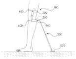
도 7과 도 8은 본 발명의 일 실시예에 따른 보행 보조기의 사용 상태도로서, 도 7은 계단을 내려갈 때의 모습을 도시한 사용 상태도이며, 도 8은 사용자의 후방에서 바라본 보행 보조기의 장착 모습이다.7 and 8 are views showing the use state of the walking aids according to an embodiment of the present invention, Fig. 7 is a state of use when the user steps down the stairs, Fig. 8 is a view to be.
도 7과 도 8에 도시된 바와 같이, 사용자가 본 발명의 일 실시예에 따른 보행 보조기(100)를 장착하면, 상부지지대(200)에 의해 대퇴부가 감싸져서 지지되고 하부지지대(300)에 의해 종아리부가 감싸져서 지지된다.7 and 8, when the user mounts the walking aids 100 according to an embodiment of the present invention, the upper thigh is supported by the
이때, 무릎을 구부리거나 펴게 되면, 제1 힌지결합부(211)와 제2 힌지결합부(311)를 중심으로 상부지지대(200)와 하부지지대(300)가 상대 회전하면서 다리 모양에 맞춰 보행 보조기(100)의 형태가 변형된다.At this time, when the knee is bent or stretched, the
하부지지대(300)의 후방에서 하향 연장되어 지면에 지지되는 보조다리(500)로 인해 사용자의 다리 뒷부분이 지지되며, 따라서 사용자의 다리 힘이 풀리면서 순간적으로 균형을 잃고 뒤로 넘어지게 되는 것을 방지할 수 있다.The rear leg of the user is supported by the
아울러, 사용자는 계단(10)을 내려갈 때, 보조다리(500)의 지지부(520)를 계단(10)의 단턱(20)에 접촉시켜 아래로 미끄러트림으로써, 발 디딜 곳을 확실히 확보하는 한편, 계단(10)을 디딜 때 전달되는 하중을 보조다리(500)로 분산시킬 수 있다. 즉, 사용자가 계단(10)을 밟을 때 지지부(520)가 계단(10)의 단턱(20)을 따라 미끄러져 내려감으로써, 사용자의 발바닥과 지지부(520)가 동일한 층계 상에 동시에 안착되어, 안정적인 자세로 계단(10)을 밟을 수 있게 되는 것이다.In addition, when the user descends the
한편, 도 9와 도 10은 본 발명의 또 다른 실시예에 따른 보조다리의 결합 단면도이다.9 and 10 are sectional views of the auxiliary legs according to another embodiment of the present invention.
본 발명의 또 다른 실시예에 의하면, 하부지지대(300)와 지지부(520,520')에 대하여 보조다리(500)의 각도를 자유롭게 조절할 수 있다.According to another embodiment of the present invention, the angle of the
이를 위해, 보조다리(500)의 양단에 구형의 회전볼(515)이 구비되고, 하부지지대(300)와 지지부(520,520')에는 회전볼(515)이 수용되도록 볼 수용홈(610)이 형성된 보조다리 결합부(600)가 각각 구비된다. 회전볼(515)은 보조다리 결합부(600)의 볼 수용홈(610) 내에서 자유롭게 회전할 수 있으며, 이에 따라 하부지지대(300)와 지지부(520,520')에 대한 보조다리(500)의 각도를 자유롭게 조절할 수 있다. 물론, 보조다리(500) 회전시 보조다리(500)의 일측이 하부지지대(300) 또는 지지부(520,520')의 일측에 걸리게 되는 경우에는 그 회전 각도가 제한될 수 있다.For this, a spherical
도 9는 하부지지대(300)의 일측에 보조다리 결합부(600)가 구비되고, 이 보조다리 결합부(600)의 볼 수용홈(610)에 절곡부재(511) 끝단의 회전볼(515)이 수용된 모습을 도시하고 있다.9 is a perspective view showing a state in which the
회전볼(515)은 절곡부재(511)와 일체로 형성되는 것이 바람직하며, 절곡부재(511)의 끝단은 테이퍼져서 절곡부재(511)의 회전 각도가 최대한 확보되게끔 하는 것이 바람직하다.It is preferable that the
보조다리 결합부(600)는 하부지지대(300)와 일체로 형성될 수도 있고, 하부지지대(300)와 별개의 부품으로 제작되어 하부지지대(300)의 일측에 결합되는 것도 가능하다.The auxiliary
보조다리 결합부(600)에는 회전볼(515)을 수용하기 위한 볼 수용홈(610)이 형성된다. 이때, 볼 수용홈(610)은 구형의 공간부로 형성되는 것이 바람직하다. 회전볼(515)을 볼 수용홈(610) 내에 용이하게 삽입하기 위해, 보조다리 결합부(600)는 2개의 분리 가능한 부재의 결합에 의해 형성될 수 있다. 다른 예로서, 볼 수용홈(610)의 입구 면적을 회전볼(515)의 직경 보다 크게 하여 회전볼(515)을 볼 수용홈(610)에 삽입한 후, 후술하는 가압부(620)를 회전볼(515) 방향으로 밀착시켜 회전볼(515)의 이탈을 방지하는 것도 가능하다.The auxiliary
보조다리 결합부(600)의 일측에는 예컨대 나비볼트 등의 조절구(630)가 결합된다. 조절구(630)의 일단은 보조다리 결합부(600)를 관통하여 볼 수용홈(610) 내부로 연장되며, 볼 수용홈(610) 내부로 연장된 조절구(630)의 일단에는 회전볼(515)을 가압하기 위한 가압부(620)가 구비된다. 이 가압부(620)는 회전볼(515)의 이탈을 방지하는 한편, 볼 수용홈(610) 내에 회전볼(515)을 가압 고정시키기 위한 것으로, 가압부(620)의 회전볼(515) 대향면은 회전볼(515)의 외주면과 대응되는 곡면으로 형성되는 것이 바람직하다.An
본 발명의 또 다른 실시예에 의하면, 도 10과 같이 회전볼(515)이 볼 수용홈(610) 내에서 자유롭게 회전 가능함에 따라, 하부지지대(300)에 구비되는 보조다리 결합부(600)에 대하여 절곡부재(511)를 상하좌우 및 대각선 방향으로 자유롭게 회전시킬 수 있다.According to another embodiment of the present invention, as the
이처럼 절곡부재(511)를 회전시켜 원하는 각도로 조절한 후에는, 조절구(630)를 조작하여 가압부(620)가 회전볼(515)의 일측에 밀착시킨다. 이때, 가압부(620)는 회전볼(515)의 일측을 가압 지지하며, 회전볼(515)의 타측이 볼 수용홈(610)의 내벽에 가압 지지됨으로써, 마찰력에 의해 회전볼(515)과 절곡부재(511)의 고정이 이루어진다.After the bending
한편, 상술한 설명에서는 절곡부재(511) 끝단의 회전볼(515)이 하부지지대(300)의 보조다리 결합부(600)에 결합되는 예를 설명하였으나, 높이조절부재(512)의 끝단에 회전볼(515)이 구비되고 이 회전볼(515)이 지지부(520,520')의 보조다리 결합부(600)에 동일한 방식으로 결합될 수 있음은 물론이다. 이때, 지지부(520,520')의 상측에 전술한 실시예의 삽입부(524,525') 대신 보조다리 결합부(600)가 형성되고, 이 보조다리 결합부(600)의 볼 수용홈(610)에 높이조절부재(512) 끝단의 회전볼(515)이 결합된다. 따라서 사용자는 지지부(520,520')를 보조다리(500)에 대하여 지면과 평행하게 회전시켜 안정적으로 안착시킬 수 있다.In the above description, the
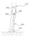
도 11과 도 12는 본 발명의 또 다른 실시예에 따른 보행 보조기의 사용 상태도이다.11 and 12 are views showing the use state of the walking aid according to another embodiment of the present invention.
도 11에 도시된 바와 같이, 본 발명의 또 다른 실시예에 따르면 하부지지대(300)에 대하여 보조다리(500)를 후방으로 회전시켜, 하부지지대(300)와 보조다리(500)의 각도를 넓게 벌릴 수 있다. 이 경우, 보조다리(500)가 지면에 더욱 안정적으로 지지된다.11, according to another embodiment of the present invention, the
또한, 도 12에 도시된 바와 같이 다리가 일측으로 휘어진 장애인의 경우, 보조다리(500)를 반대쪽으로 소정 각도 회전시켜 지면에 수직으로 지지되게 할 수 있다.12, in the case of a disabled person whose legs are curved to one side, the
아울러, 도 11과 도 12에 도시된 실시예는 하부지지대(300)에 보조다리 결합부(600)가 구비되어 보조다리(500)의 각도를 조절하는 예를 도시하고 있으나, 이때 지지부(520,520')에도 보조다리 결합부(600)가 구비되어 보조다리(500)에 대하여 지지부(520,520')를 지면과 평행하게 회전시킬 수 있음은 물론이다.11 and 12 illustrate an example of adjusting the angle of the
한편, 이처럼 보조다리 결합부(600)가 하부지지대(300) 및/또는 지지부(520,520')에 구비되는 경우에도, 전술한 실시예와 마찬가지로 상부지지대(200)를 함께 이용하거나, 상부지지대(200) 없이 하부지지대(300)와 보조다리(500)만을 사용하여 의족기로 활용하는 것도 가능하다. 이 경우 안정적인 보행을 위해 복수 개의 보조다리(500)를 구비할 수 있다.When the auxiliary
도 13은 본 발명의 또 다른 실시예에 따라 꺾임부가 형성된 보행 보조기의 사용 상태도이다.13 is a view illustrating a state of use of a walking aid provided with a bent portion according to another embodiment of the present invention.
본 발명의 또 다른 실시예에 의하면 보조다리(500)의 하단부 즉, 높이조절부재(512)의 하단부에 후방으로 소정 각도 꺾인 꺾임부(516)가 형성될 수 있다. 이때 지지부(520,520')는 보조다리(500)의 후방에 이격하여 위치하게 되며, 따라서 사용자의 다리를 더욱 안정적으로 지지하는 효과가 있다.According to another embodiment of the present invention, a
이때, 지지부(520,520')의 삽입부(524,525')는 꺾임부(516)의 각도에 대응하여 전방으로 경사지게 형성되는 것이 바람직하다.At this time, the
다른 예로서, 꺾임부(516)의 하단에 회전볼(515)이 구비되고 지지부(520,520')에 보조다리 결합부(600)를 형성하여, 지지부(520,520')를 지면에 평행하게 안착시킬 수 있다.As another example, the
이때, 보조다리(500)의 상단에 회전볼(515)이 구비되고 하부지지대(300)에 보조다리 결합부(600)가 형성되어, 보조다리(500)를 하부지지대(300)에 대하여 원하는 각도로 회전시킬 수도 있음은 물론이다.At this time, the
또한, 전술한 실시예와 마찬가지로 상부지지대(200)를 함께 이용하거나, 상부지지대(200) 없이 하부지지대(300)와 보조다리(500)만을 사용하여 의족기로 활용하는 것도 가능하다. 이 경우 안정적인 보행을 위해 복수 개의 보조다리(500)를 구비할 수 있다.It is also possible to use the
이상에서 본 발명의 실시예에 관하여 설명하였으나, 본 발명이 속하는 기술분야에서 통상의 지식을 가진 자라면 본 발명의 특허청구범위를 벗어남이 없이 다양하게 변형 실시할 수 있을 것으로 이해된다.While the present invention has been particularly shown and described with reference to exemplary embodiments thereof, it is to be understood that the invention is not limited to the disclosed exemplary embodiments.
100 : 보행 보조기
200 : 상부지지대
300 : 하부지지대
400 : 탄성밴드
500 : 보조다리
510 : 연장부
511 : 절곡부재
512 : 높이조절부재
520,520' : 지지부
600 : 보조다리 결합부
610 : 볼 수용홈
620 : 가압부
630 : 조절구100: Walking aids
200: upper support
300: lower support
400: elastic band
500: auxiliary bridge
510: Extension
511: Bending member
512: height adjustment member
520, 520 '
600: auxiliary leg coupling portion
610: Ball receiving groove
620:
630:
Claims (20)
Translated fromKorean종아리부의 일측을 감싸서 지지하며, 좌우 양단에서 제2 결합부가 상향 연장 형성되어 상기 제1 결합부와 힌지결합하는 하부지지대; 및
상기 하부지지대의 후방에 일단이 결합되고, 타단이 하향 연장되어 지면에 지지되는 보조다리를 포함하며,
상기 보조다리는, 상기 하부지지대의 후방에 일단이 결합되고 타단이 지면 방향으로 연장되며 길이 조절이 가능한 연장부와, 상기 연장부의 하단에 형성되는 지지부를 포함하되, 상기 지지부는 플레이트 형상으로서 지면에 안정적으로 지지되는 것을 특징으로 하는 보행 보조기.An upper support which supports and supports one side of the thighs and has a first coupling portion extending downward from both left and right ends thereof;
A lower support which surrounds and supports one side of the calf portion and is hinged to the first engagement portion by extending the second engagement portion upward at both the left and right ends; And
And a subsidiary leg connected to one end of the lower support and one end of which is extended downward and supported on the ground,
The auxiliary leg includes an extension part having one end connected to the rear of the lower support and the other end extending in the direction of the ground and being adjustable in length and a support part formed at the lower end of the extension part, Wherein the support member is stably supported.
상기 하부지지대의 둘레를 따라 상기 보조다리가 복수 개 구비되는 것을 특징으로 하는 보행 보조기.The method according to claim 1,
And a plurality of auxiliary legs are provided along the periphery of the lower support.
상기 연장부는, 상기 하부지지대의 후방에 결합되어 하향 절곡되는 절곡부재와, 상기 절곡부재의 중공에 삽입되어 길이가 조절되는 높이조절부재를 포함하는 것을 특징으로 하는 보행 보조기.The method according to claim 1,
Wherein the extending portion includes a folding member coupled to the rear of the lower support and bent downward, and a height adjusting member inserted into the hollow of the folding member to adjust the length thereof.
상기 지지부의 상측에 상기 연장부의 하단이 삽입 결합되는 삽입부가 돌출 형성되는 것을 특징으로 하는 보행 보조기.The method according to claim 1,
And an inserting portion to which a lower end of the extending portion is inserted is formed to protrude from the upper side of the supporting portion.
상기 지지부는 편자 형태이며, 상기 지지부의 양단이 상기 연장부의 후방으로 연장 형성되는 것을 특징으로 하는 보행 보조기.The method of claim 6,
Wherein the support portion is in the form of a horseshoe, and both ends of the support portion are formed to extend rearward of the extended portion.
상기 지지부의 하단에 탄성재질의 충격흡수부재가 구비되는 것을 특징으로 하는 보행 보조기.The method according to claim 1,
And a shock absorbing member made of an elastic material is provided at the lower end of the support portion.
상기 지지부는, 상기 연장부의 하단이 상단에 결합되고 내부에 공간부가 형성되는 몸체와, 상기 공간부의 일측에 구비되는 탄성부재와, 상기 탄성부재에 의해 상기 몸체의 후방으로 탄성 지지되는 돌출부재를 포함하는 것을 특징으로 하는 보행 보조기.The method according to claim 1,
The support portion includes a body having a lower end coupled to an upper end of the extension portion and having a space portion formed therein, an elastic member provided at one side of the space portion, and a protrusion member elastically supported to the rear of the body by the elastic member Wherein the walking assist device comprises:
상기 돌출부재의 단부에 탄성재질의 충격흡수부재가 구비되는 것을 특징으로 하는 보행 보조기.The method of claim 9,
And an impact absorbing member made of an elastic material is provided at an end of the protruding member.
상기 상부지지대의 좌우 양단부는 전방에서 서로 이격하며, 상기 상부지지대의 좌우 양단에 상기 상부지지대 전방의 이격 공간부를 가로지르는 탄성밴드의 양단이 결합되는 것을 특징으로 하는 보행 보조기.The method according to claim 1,
Wherein both left and right ends of the upper support are spaced apart from each other and both ends of an elastic band crossing the spacing space in front of the upper support are coupled to both left and right ends of the upper support.
상기 하부지지대의 후방에 일단이 결합되고, 타단이 하향 연장되어 지면에 지지되는 보조다리를 포함하며,
상기 보조다리는, 상기 하부지지대의 후방에 일단이 결합되고 타단이 지면 방향으로 연장되며 길이 조절이 가능한 연장부와, 상기 연장부의 하단에 형성되는 지지부를 포함하되, 상기 지지부는 플레이트 형상으로서 지면에 안정적으로 지지되는 것을 특징으로 하는 보행 보조기.A lower support for supporting and supporting one side of the calf; And
And a subsidiary leg connected to one end of the lower support and one end of which is extended downward and supported on the ground,
The auxiliary leg includes an extension part having one end connected to the rear of the lower support and the other end extending in the direction of the ground and being adjustable in length and a support part formed at the lower end of the extension part, Wherein the support member is stably supported.
상기 하부지지대의 둘레를 따라 상기 보조다리가 복수 개 구비되는 것을 특징으로 하는 보행 보조기.The method of claim 12,
And a plurality of auxiliary legs are provided along the periphery of the lower support.
상기 하부지지대의 후방에 보조다리 결합부가 구비되고, 상기 보조다리의 일단이 상기 보조다리 결합부에 회전 가능하게 결합되는 것을 특징으로 하는 보행 보조기.The method according to claim 1 or 12,
Wherein the auxiliary support leg is provided at the rear of the lower support, and one end of the auxiliary leg is rotatably coupled to the auxiliary leg attachment portion.
상기 보조다리의 일단에 회전볼이 형성되고, 상기 보조다리 결합부에는 상기 회전볼이 수용되는 볼 수용홈이 형성되는 것을 특징으로 하는 보행 보조기.16. The method of claim 15,
Wherein a rotating ball is formed at one end of the auxiliary leg and a ball receiving groove is formed in the auxiliary leg coupling portion to receive the rotating ball.
상기 보조다리 결합부의 일측을 관통하여 상기 볼 수용홈으로 조절구가 삽입되고, 상기 조절구의 일단에는 가압부가 구비되며, 상기 조절구에 의해 상기 가압부가 상기 회전볼의 일측을 가압하여 고정시키는 것을 특징으로 하는 보행 보조기.18. The method of claim 16,
A control member is inserted into the ball receiving groove through one side of the auxiliary leg engagement portion, and a pressing portion is provided at one end of the control member, and the pressing portion presses and fixes one side of the rotating ball by the control member A walking aids.
상기 지지부의 상측에 보조다리 결합부가 구비되고, 상기 연장부가 상기 보조다리 결합부에 회전 가능하게 결합되는 것을 특징으로 하는 보행 보조기.The method according to claim 1 or 12,
Wherein the auxiliary leg coupling portion is provided on the upper side of the support portion, and the extension portion is rotatably coupled to the auxiliary leg coupling portion.
상기 연장부의 일단에 회전볼이 형성되고, 상기 보조다리 결합부에는 상기 회전볼이 수용되는 볼 수용홈이 형성되는 것을 특징으로 하는 보행 보조기.19. The method of claim 18,
Wherein a rotation ball is formed at one end of the extended portion, and a ball receiving groove is formed in the auxiliary leg coupling portion to receive the rotation ball.
상기 연장부의 하단부에 후방으로 소정 각도 꺾인 꺾임부가 형성되는 것을 특징으로 하는 보행 보조기.
The method according to claim 1 or 12,
And a bent portion bent backward at a predetermined angle is formed at a lower end portion of the extended portion.
Priority Applications (2)
| Application Number | Priority Date | Filing Date | Title |
|---|---|---|---|
| KR1020140081627AKR101469628B1 (en) | 2014-07-01 | 2014-07-01 | Walking supporter |
| PCT/KR2015/006607WO2016003125A1 (en) | 2014-07-01 | 2015-06-29 | Walking aid apparatus |
Applications Claiming Priority (1)
| Application Number | Priority Date | Filing Date | Title |
|---|---|---|---|
| KR1020140081627AKR101469628B1 (en) | 2014-07-01 | 2014-07-01 | Walking supporter |
Publications (1)
| Publication Number | Publication Date |
|---|---|
| KR101469628B1true KR101469628B1 (en) | 2014-12-10 |
Family
ID=52677807
Family Applications (1)
| Application Number | Title | Priority Date | Filing Date |
|---|---|---|---|
| KR1020140081627AExpired - Fee RelatedKR101469628B1 (en) | 2014-07-01 | 2014-07-01 | Walking supporter |
Country Status (2)
| Country | Link |
|---|---|
| KR (1) | KR101469628B1 (en) |
| WO (1) | WO2016003125A1 (en) |
Cited By (2)
| Publication number | Priority date | Publication date | Assignee | Title |
|---|---|---|---|---|
| KR20200143820A (en)* | 2019-06-17 | 2020-12-28 | 노태진 | Walking assistance device |
| KR102337390B1 (en)* | 2021-03-24 | 2021-12-08 | 이춘식 | Walking assistance apparatus for lower limb |
Families Citing this family (3)
| Publication number | Priority date | Publication date | Assignee | Title |
|---|---|---|---|---|
| ITUA20162916A1 (en) | 2016-04-27 | 2017-10-27 | Perini Fabio Spa | ROLLING CUTTING MACHINE WITH SHARPENING WHEELS AND SHARPENING METHOD |
| CN106726043A (en)* | 2016-12-26 | 2017-05-31 | 中国人民解放军第五三中心医院 | Spinal injury rehabilitation training and protective garment |
| CN114533499B (en)* | 2022-01-19 | 2025-02-18 | 合肥工业大学 | A control system and control method for lower limb assistive device |
Citations (4)
| Publication number | Priority date | Publication date | Assignee | Title |
|---|---|---|---|---|
| JPH09502366A (en)* | 1993-07-09 | 1997-03-11 | キネティクス・インコーポレーテッド | Exercise equipment and technology |
| JP2001224612A (en)* | 2000-02-17 | 2001-08-21 | Ryosuke Ogura | Walking aid |
| KR101112119B1 (en)* | 2009-09-08 | 2012-02-22 | (주)오케이메디텍 | Orthopedic knee joint brace |
| JP2012110396A (en)* | 2010-11-22 | 2012-06-14 | Emi Yasui | Walking aid |
Family Cites Families (3)
| Publication number | Priority date | Publication date | Assignee | Title |
|---|---|---|---|---|
| US20080108917A1 (en)* | 1993-07-09 | 2008-05-08 | Kinetecs, Inc. | Exercise apparatus and technique |
| KR101141905B1 (en)* | 2010-05-28 | 2012-05-03 | 한양대학교 산학협력단 | Walking aid apparatus for knee patient |
| JP2013150714A (en)* | 2012-01-25 | 2013-08-08 | Toyota Motor Corp | Walking support device |
- 2014
- 2014-07-01KRKR1020140081627Apatent/KR101469628B1/ennot_activeExpired - Fee Related
- 2015
- 2015-06-29WOPCT/KR2015/006607patent/WO2016003125A1/enactiveApplication Filing
Patent Citations (4)
| Publication number | Priority date | Publication date | Assignee | Title |
|---|---|---|---|---|
| JPH09502366A (en)* | 1993-07-09 | 1997-03-11 | キネティクス・インコーポレーテッド | Exercise equipment and technology |
| JP2001224612A (en)* | 2000-02-17 | 2001-08-21 | Ryosuke Ogura | Walking aid |
| KR101112119B1 (en)* | 2009-09-08 | 2012-02-22 | (주)오케이메디텍 | Orthopedic knee joint brace |
| JP2012110396A (en)* | 2010-11-22 | 2012-06-14 | Emi Yasui | Walking aid |
Cited By (3)
| Publication number | Priority date | Publication date | Assignee | Title |
|---|---|---|---|---|
| KR20200143820A (en)* | 2019-06-17 | 2020-12-28 | 노태진 | Walking assistance device |
| KR102238690B1 (en) | 2019-06-17 | 2021-04-09 | 노태진 | Walking assistance device |
| KR102337390B1 (en)* | 2021-03-24 | 2021-12-08 | 이춘식 | Walking assistance apparatus for lower limb |
Also Published As
| Publication number | Publication date |
|---|---|
| WO2016003125A1 (en) | 2016-01-07 |
Similar Documents
| Publication | Publication Date | Title |
|---|---|---|
| US5941263A (en) | Leg support crutch | |
| KR101469628B1 (en) | Walking supporter | |
| EP2442763B1 (en) | Orthotic lift apparatus | |
| US5178595A (en) | Walking device to assist those with an injury to a lower limb | |
| US8021316B2 (en) | Weight-bearing lower extremity brace | |
| US8403872B2 (en) | Weight-bearing lower extremity brace | |
| JP2002510531A (en) | Crutch device | |
| US20100174219A1 (en) | Weight-bearing lower extremity brace | |
| US10493322B2 (en) | Human hand-crawling apparatus | |
| CA2935571C (en) | Lower extremity isolating leg brace | |
| KR101975493B1 (en) | a walking buffer orthosis | |
| KR20160023293A (en) | Wearing crutch | |
| KR101413329B1 (en) | Walk assistance apparatus | |
| JP2018079132A (en) | Inferior limb motion support appliance | |
| KR102071611B1 (en) | Auxiliary apparatus for assisting muscular strength of ankle | |
| US20120290102A1 (en) | Knee Crutch System | |
| JP6530269B2 (en) | Elbow clutch | |
| JP6396126B2 (en) | Lower limb orthosis | |
| CN106726373A (en) | A kind of interim walking auxiliary robot | |
| CN210785275U (en) | Medical rehabilitation auxiliary walker for ankle orthopedics | |
| JP6932831B2 (en) | Exo skeleton subassemblies and exo skeleton structures containing such subassemblies | |
| KR101829972B1 (en) | Equipment of leg exercises for knee joint patient | |
| JP6713124B1 (en) | Rear brace of ankle foot orthosis and ankle foot orthosis | |
| CA2543217C (en) | Pressure off knee brace | |
| CN116270144A (en) | Auxiliary support for walking of lower limb without load |
Legal Events
| Date | Code | Title | Description |
|---|---|---|---|
| PA0109 | Patent application | St.27 status event code:A-0-1-A10-A12-nap-PA0109 | |
| PA0201 | Request for examination | St.27 status event code:A-1-2-D10-D11-exm-PA0201 | |
| PA0302 | Request for accelerated examination | St.27 status event code:A-1-2-D10-D17-exm-PA0302 St.27 status event code:A-1-2-D10-D16-exm-PA0302 | |
| PE0902 | Notice of grounds for rejection | St.27 status event code:A-1-2-D10-D21-exm-PE0902 | |
| E13-X000 | Pre-grant limitation requested | St.27 status event code:A-2-3-E10-E13-lim-X000 | |
| P11-X000 | Amendment of application requested | St.27 status event code:A-2-2-P10-P11-nap-X000 | |
| E13-X000 | Pre-grant limitation requested | St.27 status event code:A-2-3-E10-E13-lim-X000 | |
| P11-X000 | Amendment of application requested | St.27 status event code:A-2-2-P10-P11-nap-X000 | |
| P13-X000 | Application amended | St.27 status event code:A-2-2-P10-P13-nap-X000 | |
| PE0801 | Dismissal of amendment | St.27 status event code:A-2-2-P10-P12-nap-PE0801 | |
| E701 | Decision to grant or registration of patent right | ||
| PE0701 | Decision of registration | St.27 status event code:A-1-2-D10-D22-exm-PE0701 | |
| GRNT | Written decision to grant | ||
| PR0701 | Registration of establishment | St.27 status event code:A-2-4-F10-F11-exm-PR0701 | |
| PR1002 | Payment of registration fee | St.27 status event code:A-2-2-U10-U11-oth-PR1002 Fee payment year number:1 | |
| PG1601 | Publication of registration | St.27 status event code:A-4-4-Q10-Q13-nap-PG1601 | |
| PN2301 | Change of applicant | St.27 status event code:A-5-5-R10-R11-asn-PN2301 | |
| PN2301 | Change of applicant | St.27 status event code:A-5-5-R10-R14-asn-PN2301 | |
| R18-X000 | Changes to party contact information recorded | St.27 status event code:A-5-5-R10-R18-oth-X000 | |
| P22-X000 | Classification modified | St.27 status event code:A-4-4-P10-P22-nap-X000 | |
| R18-X000 | Changes to party contact information recorded | St.27 status event code:A-5-5-R10-R18-oth-X000 | |
| LAPS | Lapse due to unpaid annual fee | ||
| PC1903 | Unpaid annual fee | St.27 status event code:A-4-4-U10-U13-oth-PC1903 Not in force date:20171202 Payment event data comment text:Termination Category : DEFAULT_OF_REGISTRATION_FEE | |
| PC1903 | Unpaid annual fee | St.27 status event code:N-4-6-H10-H13-oth-PC1903 Ip right cessation event data comment text:Termination Category : DEFAULT_OF_REGISTRATION_FEE Not in force date:20171202 | |
| P22-X000 | Classification modified | St.27 status event code:A-4-4-P10-P22-nap-X000 |