KR101466985B1 - Display device - Google Patents
Display deviceDownload PDFInfo
- Publication number
- KR101466985B1 KR101466985B1KR1020080031399AKR20080031399AKR101466985B1KR 101466985 B1KR101466985 B1KR 101466985B1KR 1020080031399 AKR1020080031399 AKR 1020080031399AKR 20080031399 AKR20080031399 AKR 20080031399AKR 101466985 B1KR101466985 B1KR 101466985B1
- Authority
- KR
- South Korea
- Prior art keywords
- resolution
- data
- images
- pixel array
- displayed
- Prior art date
- Legal status (The legal status is an assumption and is not a legal conclusion. Google has not performed a legal analysis and makes no representation as to the accuracy of the status listed.)
- Expired - Fee Related
Links
Images


Classifications
- G—PHYSICS
- G02—OPTICS
- G02F—OPTICAL DEVICES OR ARRANGEMENTS FOR THE CONTROL OF LIGHT BY MODIFICATION OF THE OPTICAL PROPERTIES OF THE MEDIA OF THE ELEMENTS INVOLVED THEREIN; NON-LINEAR OPTICS; FREQUENCY-CHANGING OF LIGHT; OPTICAL LOGIC ELEMENTS; OPTICAL ANALOGUE/DIGITAL CONVERTERS
- G02F1/00—Devices or arrangements for the control of the intensity, colour, phase, polarisation or direction of light arriving from an independent light source, e.g. switching, gating or modulating; Non-linear optics
- G02F1/01—Devices or arrangements for the control of the intensity, colour, phase, polarisation or direction of light arriving from an independent light source, e.g. switching, gating or modulating; Non-linear optics for the control of the intensity, phase, polarisation or colour
- G02F1/13—Devices or arrangements for the control of the intensity, colour, phase, polarisation or direction of light arriving from an independent light source, e.g. switching, gating or modulating; Non-linear optics for the control of the intensity, phase, polarisation or colour based on liquid crystals, e.g. single liquid crystal display cells
- G02F1/133—Constructional arrangements; Operation of liquid crystal cells; Circuit arrangements
- G—PHYSICS
- G09—EDUCATION; CRYPTOGRAPHY; DISPLAY; ADVERTISING; SEALS
- G09G—ARRANGEMENTS OR CIRCUITS FOR CONTROL OF INDICATING DEVICES USING STATIC MEANS TO PRESENT VARIABLE INFORMATION
- G09G3/00—Control arrangements or circuits, of interest only in connection with visual indicators other than cathode-ray tubes
- G09G3/20—Control arrangements or circuits, of interest only in connection with visual indicators other than cathode-ray tubes for presentation of an assembly of a number of characters, e.g. a page, by composing the assembly by combination of individual elements arranged in a matrix no fixed position being assigned to or needed to be assigned to the individual characters or partial characters
- G09G3/34—Control arrangements or circuits, of interest only in connection with visual indicators other than cathode-ray tubes for presentation of an assembly of a number of characters, e.g. a page, by composing the assembly by combination of individual elements arranged in a matrix no fixed position being assigned to or needed to be assigned to the individual characters or partial characters by control of light from an independent source
- G09G3/36—Control arrangements or circuits, of interest only in connection with visual indicators other than cathode-ray tubes for presentation of an assembly of a number of characters, e.g. a page, by composing the assembly by combination of individual elements arranged in a matrix no fixed position being assigned to or needed to be assigned to the individual characters or partial characters by control of light from an independent source using liquid crystals
- G—PHYSICS
- G09—EDUCATION; CRYPTOGRAPHY; DISPLAY; ADVERTISING; SEALS
- G09G—ARRANGEMENTS OR CIRCUITS FOR CONTROL OF INDICATING DEVICES USING STATIC MEANS TO PRESENT VARIABLE INFORMATION
- G09G2340/00—Aspects of display data processing
- G09G2340/04—Changes in size, position or resolution of an image
- G09G2340/0407—Resolution change, inclusive of the use of different resolutions for different screen areas
- G—PHYSICS
- G09—EDUCATION; CRYPTOGRAPHY; DISPLAY; ADVERTISING; SEALS
- G09G—ARRANGEMENTS OR CIRCUITS FOR CONTROL OF INDICATING DEVICES USING STATIC MEANS TO PRESENT VARIABLE INFORMATION
- G09G3/00—Control arrangements or circuits, of interest only in connection with visual indicators other than cathode-ray tubes
- G09G3/20—Control arrangements or circuits, of interest only in connection with visual indicators other than cathode-ray tubes for presentation of an assembly of a number of characters, e.g. a page, by composing the assembly by combination of individual elements arranged in a matrix no fixed position being assigned to or needed to be assigned to the individual characters or partial characters
- G09G3/34—Control arrangements or circuits, of interest only in connection with visual indicators other than cathode-ray tubes for presentation of an assembly of a number of characters, e.g. a page, by composing the assembly by combination of individual elements arranged in a matrix no fixed position being assigned to or needed to be assigned to the individual characters or partial characters by control of light from an independent source
- G09G3/36—Control arrangements or circuits, of interest only in connection with visual indicators other than cathode-ray tubes for presentation of an assembly of a number of characters, e.g. a page, by composing the assembly by combination of individual elements arranged in a matrix no fixed position being assigned to or needed to be assigned to the individual characters or partial characters by control of light from an independent source using liquid crystals
- G09G3/3611—Control of matrices with row and column drivers
- G09G3/3648—Control of matrices with row and column drivers using an active matrix
- G—PHYSICS
- G09—EDUCATION; CRYPTOGRAPHY; DISPLAY; ADVERTISING; SEALS
- G09G—ARRANGEMENTS OR CIRCUITS FOR CONTROL OF INDICATING DEVICES USING STATIC MEANS TO PRESENT VARIABLE INFORMATION
- G09G5/00—Control arrangements or circuits for visual indicators common to cathode-ray tube indicators and other visual indicators
- G09G5/14—Display of multiple viewports
Landscapes
- Physics & Mathematics (AREA)
- Engineering & Computer Science (AREA)
- General Physics & Mathematics (AREA)
- Computer Hardware Design (AREA)
- Theoretical Computer Science (AREA)
- Chemical & Material Sciences (AREA)
- Crystallography & Structural Chemistry (AREA)
- Nonlinear Science (AREA)
- Mathematical Physics (AREA)
- Optics & Photonics (AREA)
- Control Of Indicators Other Than Cathode Ray Tubes (AREA)
Abstract
Translated fromKoreanDescription
Translated fromKorean본 발명은 액정표시장치(LCD), 전계 방출 표시장치(FED), 플라즈마 디스플레이 패널(PDP) 및 유기 발광다이오드소자(OLED) 등의 평판 표시장치에 관한 것이다.The present invention relates to a flat panel display such as a liquid crystal display (LCD), a field emission display (FED), a plasma display panel (PDP) and an organic light emitting diode (OLED)
액티브 매트릭스(Active Matrix) 구동방식의 액정표시장치는 스위칭 소자로서 박막트랜지스터(Thin Film Transistor : 이하 "TFT"라 함)를 이용하여 동영상을 표시하고 있다. 이 액정표시장치는 음극선관(Cathode Ray Tube, CRT)에 비하여 소형화가 가능하여 휴대용 정보기기, 사무기기, 컴퓨터 등에서 표시기에 응용됨은 물론, 텔레비젼에도 응용되어 음극선관을 빠르게 대체하고 있다.A liquid crystal display device of an active matrix driving type displays a moving picture by using a thin film transistor (hereinafter referred to as "TFT") as a switching element. This liquid crystal display device can be downsized as compared with a cathode ray tube (CRT), and is applied to a display device in a portable information device, an office machine, a computer, etc., and is also applied to a television, thereby quickly replacing a cathode ray tube.
액정표시장치에서 화상이 표시되는 픽셀 어레이에는 R 서브필셀, G 서브필셀 및 B 서브픽셀을 각각 포함한 다수의 픽셀들이 매트릭스 형태로 배치된다. 픽셀 어레이의 해상도는 도 1과 같이 가로행의 픽셀수(x)와 세로열의 픽셀수(y)에 따라 결정된다. 현재 개인용 컴퓨터(PC)나 노트북 컴퓨터(Notebook computer)의 모니터에 적용되는 해상되는 표 1과 같다.In a pixel array in which an image is displayed in the liquid crystal display device, a plurality of pixels each including an R subpixel, a G subpixel, and a B subpixel are arranged in a matrix form. The resolution of the pixel array is determined by the number of pixels (x) in the horizontal row and the number of pixels (y) in the vertical column, as shown in FIG. Table 1 shows the resolutions applied to the monitors of personal computers (PCs) and notebook computers.
이와 같은 해상도를 가지는 액정표시장치에서 하나 이상의 응용프로그램을 실행시켜 두 개 이상의 화면을 멀티 윈도우로 표시하면, 다음과 같은 문제점이 있다.When one or more application programs are executed in a liquid crystal display device having such a resolution to display two or more screens in a multi-window, the following problems occur.
제1 및 제2 윈도우(W1, W2) 각각의 이미지 전체를 한 화면에 표시하면 도 2에서 검게 표시된 표시면을 활용할 수 없어 표시면 활용도가 떨어진다. 이는 두 개의 이미지 전체를 한 화면에 표시하려면 그 이미지들의 가로와 세로가 각각의 이미지 해상도를 유지하면서 이미지들의 크기가 줄어들기 때문이다.If all of the images of the first and second windows W1 and W2 are displayed on one screen, the display surface displayed in black in FIG. 2 can not be utilized, and the utilization of the display surface becomes poor. This is because when two images are displayed on one screen, the size of the images is reduced while the width and height of the images are maintained at the respective image resolutions.
도 3 및 도 4와 같이 하나 또는 두 개의 윈도우 크기를 크게 하면 윈도우 내에 표시되는 이미지 전체가 아니라 그 이미지의 일부만이 확대된다. 이 경우에, 이미지가 확대된 윈도우에는 화면 이동을 위하여 가로 스크롤바 및/또는 세로 스크롤바가 표시된다. 사용자는 윈도우에 표시된 이미지 일부 이외의 다른 부분을 보려면 마우스를 이용하여 스크롤바를 드래깅하는 동작을 반복하여야 한다. 이 때문에 기존 해상도의 모니터를 이용하여 업무를 처리하는 사용자는 업무 효율이 떨어질 수 밖에 없다.When one or two window sizes are enlarged as shown in FIGS. 3 and 4, only a part of the image is enlarged, not the entire image displayed in the window. In this case, a horizontal scroll bar and / or a vertical scroll bar are displayed on the enlarged window of the image for screen movement. The user must repeat the operation of dragging the scroll bar with the mouse to view other parts of the image displayed on the window. For this reason, users who process tasks using existing resolution monitors are inferior in efficiency.
기존 해상도의 문제점은 액정표시장치 뿐만 아니라 전계 방출 표시장치(Field Emission Display : FED), 플라즈마 디스플레이 패널(Plasma Display Panel : PDP) 및 유기 발광다이오드소자(Organic Light Emitting Diode Device, OLED) 등에도 나타나고 있다.The problem of the conventional resolution is also seen in a field emission display (FED), a plasma display panel (PDP) and an organic light emitting diode (OLED) device as well as a liquid crystal display .
본 발명은 상기 종래 기술의 문제점들을 해결하고자 안출된 발명으로써 두 개 이상의 이미지를 한 화면에 표시할 때 표시면의 활용도를 높이고 스크롤바 없이 두 개 이상의 이미지 전체를 표시할 수 있는 해상도의 표시장치를 제공하는데 있다.Disclosure of Invention Technical Problem [8] Accordingly, the present invention has been made to solve the above-mentioned problems of the prior art, and provides a display device having a resolution capable of displaying two or more images on one screen and displaying two or more images without a scroll bar .
본 발명의 표시장치는 다수의 데이터라인들, 상기 데이터라인들과 교차되는 다수의 게이트라인들, 및 매트릭스 형태로 배치되는 다수의 픽셀들을 포함하여 두 개 이상의 이미지를 공간적으로 분할하여 동시에 표시할 수 있는 픽셀 어레이를 포함한 표시패널; 상기 데이터라인들에 데이터를 공급하는 데이터 구동회로; 상기 게이트라인들에 스캔신호를 공급하는 게이트 구동회로; 상기 두 개 이상의 이미지 각각에 대하여 해상도를 변환하는 스케일러 보드; 및 상기 스케일러 보드로부터의 데이터를 상기 데이터 구동회로에 공급하고 상기 상기 데이터 구동회로와 상기 게이트 구동회로의 동작 타이밍을 제어하는 콘트롤 보드를 구비한다.The display device of the present invention may include a plurality of data lines, a plurality of gate lines crossing the data lines, and a plurality of pixels arranged in a matrix, so that two or more images can be spatially divided and displayed simultaneously A display panel including a pixel array; A data driving circuit for supplying data to the data lines; A gate driving circuit for supplying a scan signal to the gate lines; A scaler board for converting a resolution for each of the two or more images; And a control board for supplying data from the scaler board to the data driving circuit and controlling an operation timing of the data driving circuit and the gate driving circuit.
상기 픽셀 어레이에 스크롤바 없이 SXGA 해상도의 2 개 이미지들이 표시되거나, 상기 스크롤바 없이 FHD 해상도의 1 개 이미지와 XGA 해상도의 1 개 이미지가 표시되거나 혹은, 상기 스크롤바 없이 UXGA 해상도의 2 개 이미지들이 표시되도록 상기 픽셀 어레이의 가로 대 세로의 비율은 21.3~26.7 : 10이다.Wherein two images of the SXGA resolution are displayed on the pixel array without the scroll bar or one image of the FHD resolution and one image of the XGA resolution are displayed without the scroll bar or two images of the UXGA resolution are displayed without the scroll bar, The aspect ratio of the pixel array is 21.3 to 26.7: 10.
본 발명의 표시장치는 가로 대 세로의 비율이 21.3~26.7 : 10인 해상도를 가진다. 본 발명은 이 해상도를 이용하여 비활용 영역이 거의 없이 또한 스크롤 바 없이 이미지들 각각을 한 화면에 표시할 수 있다. 나아가, 본 발명의 실시예에 따른 표시장치는 한 화면에 스크롤 바 없이 2 개 이상의 이미지를 표시할 수 있어 모니터를 이용한 업무 활용도를 높일 수 있고, 터치패널을 유저 인터페이스로 하여 이미지 제어시에 사용자의 동선을 줄일 수 있다.The display device of the present invention has a resolution of 21.3 to 26.7: 10 in the aspect ratio. The present invention can display each of the images on one screen with little or no unused area and no scroll bar using this resolution. Further, since the display device according to the embodiment of the present invention can display two or more images without a scroll bar on one screen, utilization of work using the monitor can be increased, and the user can use the touch panel as a user interface, You can reduce the copper wire.
이하, 도 5 내지 도 12를 참조하여 본 발명의 바람직한 실시예에 대하여 설명하기로 한다.Hereinafter, preferred embodiments of the present invention will be described with reference to FIGS. 5 to 12. FIG.
도 5를 참조하면, 본 발명의 제1 실시예에 따른 액정표시장치는 액정표시패널(50), 데이터 구동회로(52), 게이트 구동회로(53), 콘트롤 보드(51), 및 스케일러 보드(56)를 구비한다.5, a liquid crystal display device according to the first embodiment of the present invention includes a liquid
액정표시패널(50)은 두 장의 유리기판과, 그 기판들 사이에 형성된 액정층을 포함한다. 액정표시패널(50)에서, 데이터라인들(54)과 게이트라인들(55)의 교차 구조에 의해 매트릭스 형태로 액정셀들(Clc)이 형성된다.The liquid
액정표시패널(50)의 하부 유리기판에는 데이터라인들(54), 게이트라인들(55), TFT들, 및 스토리지 커패시터(Cst)가 형성된다. 액정셀들(Clc)은 TFT에 접속되어 화소전극들(1)과 공통전극(2) 사이의 전계에 의해 구동된다. 액정표시패널(50)의 상부 유리기판 상에는 블랙매트릭스, 컬러필터 및 공통전극(2)이 형성된다. 공통전극(2)은 TN(Twisted Nematic) 모드와 VA(Vertical Alignment) 모드와 같은 수직전계 구동방식에서 상부 유리기판 상에 형성되며, IPS(In Plane Switching) 모드와 FFS(Fringe Field Switching) 모드와 같은 수평전계 구동방식에서 화소전극(1)과 함께 하부 유리기판 상에 형성된다. 액정표시패널(50)의 상부 유리기판과 하부 유리기판 각각에는 편광판이 부착되고 액정의 프리틸트각(pre-tilt angle)을 설정하기 위한 배향막이 형성된다.
액정표시패널(50)의 해상도는 가로방향의 픽셀수(x) 대 세로방향의 픽셀수(y)로 정의되며, 그 비율은 21.3~26.7 : 10이다. 이 해상도는 영화, 게임, 문서 프로그램 등 다양한 응용 프로그램을 실행시켜 2 개 또는 3 개의 윈도우에서 2 개 또는 3 개의 이미지를 한 화면에서 동시에 표시하는 실험을 반복한 결과로 얻어졌다. 21.3~26.7 : 10의 해상도에서 3 개의 이미지를 동시에 표시하면, 활용되지 않는 표시면이 작거나 거의 없으며, 스크롤바 없이 두 개 이상의 이미지 전체를 동시에 표시할 수 있다.The resolution of the liquid
데이터 구동회로(52)는 콘트롤 보드(51)와 액정표시패널(50)의 데이터라인들(54) 사이에 접속된 다수의 데이터 드라이브 IC(Data Drive Integrated Circuit, DIC)들을 포함한다. 데이터 드라이브 IC들(DICs) 각각은 쉬프트 레지스터, 래치, 디지털-아날로그 변환기, 출력 버퍼 등을 포함한다. 이러한 데이터 드라이브 IC들(DICs) 각각은 콘트롤 보드(51)로부터의 데이터 타이밍 제어신호에 응답하여 콘트롤 보드(51)로부터의 디지털 비디오 데이터를 래치한 후, 그 디지털 비디오 데이터를 아날로그 정극성/부극성 감마보상전압으로 변환하여 데이터라인들(54)에 공급한다.The
게이트 구동회로(53)는 액정표시패널(50)의 일측 또는 양측에 배치되는 다수의 게이트 드라이브 IC들(GICs)을 포함한다. 게이트 드라이브 IC들(GICs) 각각은 콘트롤 보드(51)로부터의 게이트 타이밍 제어신호들에 응답하여 게이트펄스 즉, 스캔펄스를 게이트라인들(55)에 순차적으로 공급한다. 게이트라인들(55)에 공급되는 게이트펄스는 데이터라인들(54)에 공급되는 데이터전압에 동기된다.The
콘트롤 보드(51)는 스케일러 보드(56)로부터 입력되는 디지털 비디오 데이터를 액정표시패널(50)의 표시위치별로 분리하여 데이터 드라이브 IC들(DICs)에 공급한다. 또한, 콘트롤 보드(51)는 스케일러 보드(56)로부터 입력되는 수직 및 수평 동기신호, 데이터 인에이블신호, 도트클럭 등의 타이밍신호에 근거하여 데이터 드라이브 IC들(DICs)의 동작 타이밍을 제어하기 위한 데이터 타이밍 제어신호와, 게이트 드라이브 IC들(GICs)의 동작 타이밍을 제어하기 위한 게이트 타이밍 제어신호를 발생한다.The
스케일러 보드(56)는 다수의 영상소스로부터 입력되는 디지털 비디오 데이터들을 각 이미지별로 처리하는 다수의 스케일러를 이용하여 디지털 비디오 데이터들의 해상도를 액정표시패널(50)에 표시되는 이미지의 해상도로 변환하여 콘트롤 보드(51)에 공급한다. 그리고 스케일러 보드(56)는 수직 및 수평 동기신호, 데이터 인에이블신호, 도트클럭 등의 타이밍신호를 콘트롤 보드(51)에 공급한다.The
도 6은 도 5에 도시된 스케일러 보드(56)와 콘트롤 보드(51)의 회로 구성을 나타낸다. 도 7은 액정표시패널(50)에 표시되는 3 개의 윈도우의 이미지 예를 보여 주는 도면이다.Fig. 6 shows a circuit configuration of the
도 6 및 도 7을 참조하면, 'IS1'은 제1 윈도우(W1)에 표시되는 이미지의 디지털 비디오 데이터를 발생하는 제1 영상소스이고, 'IS2'는 제2 윈도우(W2)에 표시되는 이미지의 디지털 비디오 데이터를 발생하는 제2 영상소스이다. 그리고 'IS3'은 제3 윈도우(W3)에 표시되는 이미지의 디지털 비디오 데이터를 발생하는 제3 영상소스이다. 영상 소스는 셋톱박스(Set-top Box), DVD 플레이어(Player), 블루레이 플레이어(Blue-ray Player), 개인용 컴퓨터(PC) 등을 포함하고 또한, 개인용 컴퓨터(PC)에서 실행되는 각종 응용 프로그램을 포함한다.6 and 7, 'IS1' is a first image source for generating digital video data of an image displayed in the first window W1, 'IS2' is an image displayed in the second window W2, Lt; / RTI > digital video data. And 'IS3' is a third image source for generating digital video data of the image displayed in the third window W3. The video source includes a set-top box, a DVD player, a Blu-ray player, a personal computer (PC), and the like. .
스케일러 보드(56)는 제1 내지 제3 스케일러(611 내지 613), 제1 내지 제3 인터페이스 송신부(621 내지 623)를 구비한다. 콘트롤 보드(51)는 제1 내지 제3 인터페이스 수신부(631 내지 633), 및 타이밍 콘트롤러(64)를 구비한다.The
제1 스케일러(611)는 제1 영상소스(IS1)로부터의 디지털 비디오 데이터를 입력받아 그 디지털 비디오 데이터의 해상도를 제1 윈도우(W1)에 표시되는 이미지의 해상도로 변환하고, 변환된 해상도를 기준으로 타이밍 신호를 발생한다. 제2 스케일러(612)는 제2 영상소스(IS2)로부터의 디지털 비디오 데이터를 입력받아 그 디지털 비디오 데이터의 해상도를 제2 윈도우(W2)에 표시되는 이미지의 해상도로 변환하고, 변환된 해상도를 기준으로 타이밍 신호를 발생한다. 제3 스케일러(613)는 제3 영상소스(IS3)로부터의 디지털 비디오 데이터를 입력받아 그 디지털 비디오 데이터의 해상도를 제3 윈도우(W3)에 표시되는 이미지의 해상도로 변환하고, 변환된 해상도를 기준으로 타이밍 신호를 발생한다.The
제1 인터페이스 송신부(621)는 제1 스케일러(611)와 제1 인터페이스 수신부(631) 사이에 접속되어 제1 스케일러(611)로부터의 디지털 비디오 데이터와 타이밍 신호를 제1 인터페이스 수신부(631)에 공급한다. 제2 인터페이스 송신부(622)는 제2 스케일러(612)와 제2 인터페이스 수신부(632) 사이에 접속되어 제2 스케일러(612)로부터의 디지털 비디오 데이터와 타이밍 신호를 제2 인터페이스 수신부(632)에 공급한다. 제3 인터페이스 송신부(623)는 제3 스케일러(613)와 제3 인터페이스 수신부(633) 사이에 접속되어 제3 스케일러(613)로부터의 디지털 비디오 데이터와 타이밍 신호를 제3 인터페이스 수신부(633)에 공급한다. 인터페이스 송신부들(621 내지 623)과 인터페이스 송신부들(631 내지 633) 사이에서 디지털 비디오 데이터와 타이밍 신호들은 TMDS(Transition Minimized Differential Signaling) 인터페이스 또는 LVDS(Low Voltage Differential Signalling) 인터페이스 방식으로 전송된다.The first
타이밍 콘트롤러(51)는 인터페이스 수신부들(631 내지 633)로부터의 디지털 비디오 데이터들을 데이터 드라이브 IC들(DICs)에 분배한다. 그리고 타이밍 콘트롤러(51)는 인터페이스 수신부들(631 내지 633)로부터의 타이밍 신호들에 기초하여 데이터 드라이브 IC들(DICs)의 동작 타이밍을 제어하기 위한 데이터 타이밍 제어신호와, 게이트 드라이브 IC들(GICs)의 동작 타이밍을 제어하기 위한 게이트 타이밍 제어신호를 발생한다. 제1 영상소스(IS1)의 이미지에 포함된 디지털 비디오 데이터들은 제1 윈도우(W1) 내에 존재하는 데이터라인들에 데이터전압을 공급하는 좌측에 배치된 데이터 드라이브 IC들(DICs)에 공급된다. 제2 영상소스(IS2)의 이미지에 포함된 디지털 비디오 데이터들은 제2 윈도우(W2) 내에 존재하는 데이터라인들에 데이터전압을 공급하는 중앙에 위치한 데이터 드라이브 IC들(DICs)에 공급된다. 제3 영상소스(IS3)의 이미지에 포함된 디지털 비디오 데이터들은 제3 윈도우(W3) 내에 존재하는 데이터라인들에 데이터전압을 공급하는 우측에 위치한 데이터 드라이브 IC들(DICs)에 공급된다.The
액정표시패널(50)의 픽셀 어레이에 두 개의 이미지가 표시된다면 해상도 변환되는 영상소스는 2 개이고, 제1 내지 제3 스케일러들(611 내지 613) 중에서 2 개의 스케일러들이 타이밍 콘트롤러(64)에 해상도가 변환된 디지털 비디오 데이터를 공급한다. 그리고 영상 소스로부터 디지털 비디오 데이터를 입력 받지 않는 스케일러는 출력이 없다. 이 경우에, 타이밍 콘트롤러(64)는 하나의 인터페이스 수신부로부터 입력되는 디지털 비디오 데이터를 일측 이미지의 데이터라인들을 구동하는 데이터 드라이브 IC들에 공급하고, 다른 하나의 인터페이스 수신부로부터 입력되는 디지털 비디오 데이터를 타측 이미지의 데이터라인들을 구동하는 데이터 드라 이브 IC들에 공급한다.If two images are displayed on the pixel array of the liquid
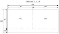
도 8은 본 발명의 제1 실시예에 따른 해상도에서 표시되는 2 개 이미지의 예를 보여 주는 도면이다.8 is a view showing an example of two images displayed at a resolution according to the first embodiment of the present invention.
도 8을 참조하면, 본 발명의 제1 실시예에 따른 해상도는 2560(가로 픽셀수)×1200(세로 픽셀수)이며, 가로 픽셀수 대 세로 픽셀수의 비율은 21.3 : 10이다. 도 8은 21.3 : 10의 해상도에서 각각 SXGA 해상도(1280×1024)를 가지는 2 개의 이미지를 표시한 예이다. SXGA 해상도의 2 개 이미지들은 21.3 : 10의 해상도를 가지는 표시면 거의 전체에서 전체에서 공간적으로 분할되어 동시에 표시될 수 있다. 따라서, 21.3 : 10의 해상도에서는 스크롤바 없이 SXGA 해상도의 2 개 이미지들이 표시될 수 있다.Referring to FIG. 8, the resolution according to the first embodiment of the present invention is 2560 (number of horizontal pixels) × 1200 (number of vertical pixels), and the ratio of the number of horizontal pixels to the number of vertical pixels is 21.3: 10. 8 shows an example of displaying two images having SXGA resolution (1280 x 1024) at a resolution of 21.3: 10. The two images of SXGA resolution can be displayed at the same time spatially dividing all over the entire display surface having a resolution of 21.3: 10. Thus, at a resolution of 21.3: 10, two images with SXGA resolution can be displayed without scrollbars.
도 9는 본 발명의 제2 실시예에 따른 해상도에서 표시되는 2 개 이미지의 예를 보여 주는 도면이다.9 is a view showing an example of two images displayed at a resolution according to the second embodiment of the present invention.
도 9를 참조하면, 본 발명의 제2 실시예에 따른 해상도는 2944(가로 픽셀수)×1200(세로 픽셀수)이며, 가로 픽셀수 대 세로 픽셀수의 비율은 24.5 : 10이다. 도 9는 24.5 : 10의 해상도에서 Full HD(high definition, FHD) 해상도(1920×1080)의 1 개 이미지와 XGA 해상도(1024×768)의 1 개 이미지를 표시한 예이다. FHD 해상도의 1 개 이미지와 XGA 해상도의 1 개 이미지는 24.5 : 10의 해상도를 가지는 표시면에 거의 전체에서 공간적으로 분할되어 표시될 수 있다. 따라서, 24.5 : 10의 해상도에서는 스크롤바 없이 FHD 해상도의 1 개 이미지와 XGA 해상도의 1 개 이미지가 표시될 수 있다.Referring to FIG. 9, the resolution according to the second embodiment of the present invention is 2944 (number of horizontal pixels) × 1200 (number of vertical pixels), and the ratio of the number of horizontal pixels to the number of vertical pixels is 24.5: 10. 9 is an example of displaying one image of Full HD (high definition (FHD) resolution (1920 x 1080) and one image of XGA resolution (1024 x 768) at a resolution of 24.5: 10. One image of the FHD resolution and one image of the XGA resolution can be displayed on the display surface having the resolution of 24.5: 10 almost spatially and spatially divided. Therefore, at a resolution of 24.5: 10, one image with FHD resolution and one image with XGA resolution can be displayed without a scroll bar.
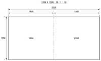
도 10은 본 발명의 제3 실시예에 따른 해상도에서 표시되는 2 개 이미지의 예를 보여 주는 도면.10 is a view showing an example of two images displayed at a resolution according to the third embodiment of the present invention;
도 10을 참조하면, 본 발명의 제3 실시예에 따른 해상도는 3200(가로 픽셀수)×1200(세로 픽셀수)이며, 가로 픽셀수 대 세로 픽셀수의 비율은 26.7 : 10이다. 도 10은 26.7 : 10의 해상도에서 UXGA 해상도(1600×1200)의 2 개 이미지들을 표시한 예이다. UXGA 해상도의 2 개 이미지는 26.7 : 10의 해상도를 가지는 표시면 거의 전체에서 공간적으로 분할되어 표시될 수 있다. 따라서, 26.7 : 10의 해상도에서는 스크롤바 없이 UXGA 해상도의 2 개 이미지들이 표시될 수 있다. 한편, 이 해상도는 문서 프로그램을 실행시켜 3 개의 윈도우들을 화면에 꽉 차게 확장시키고 각각의 윈도우들에서 A4 용지 해상도의 문서 1 페이지를 스크롤바 없이 표시할 수 있다.Referring to FIG. 10, the resolution according to the third embodiment of the present invention is 3200 (number of horizontal pixels) × 1200 (number of vertical pixels), and the ratio of the number of horizontal pixels to the number of vertical pixels is 26.7: 10. 10 shows an example of displaying two images of UXGA resolution (1600x1200) at a resolution of 26.7: 10. Two images at UXGA resolution can be displayed spatially divided almost all over the display surface having a resolution of 26.7: 10. Thus, at a resolution of 26.7: 10, two images with UXGA resolution can be displayed without a scroll bar. This resolution, on the other hand, allows a document program to be run so that three windows are fully extended on the screen, and one page of A4-resolution paper in each window can be displayed without a scroll bar.
도 8 내지 도 10의 이미지 해상도는 특정 해상도로 정해진 것이 아니라, 표 1의 해상도들 중 어떠한 것으로도 선택될 수 있고, 스케일러들은 표시 이미지의 해상도에 맞게 디지털 비디오 데이터의 해상도를 변환한다.8 to 10 may be selected from any of the resolutions of Table 1, rather than being set to a specific resolution, and the scalers may convert the resolution of the digital video data to match the resolution of the displayed image.
도 11은 본 발명의 제2 실시예에 따른 액정표시장치를 나타낸다.11 shows a liquid crystal display device according to a second embodiment of the present invention.
도 11을 참조하면, 본 발명의 제2 실시예에 따른 액정표시장치는 액정표시패널(50)과, 그 액정표시패널(50) 상에 배치된 터치패널(110)을 구비한다. 도 11에서 전술한 제1 실시예에 따른 액정표시장치와 실질적으로 동일한 회로 구성은 생략된다.Referring to FIG. 11, a liquid crystal display device according to a second embodiment of the present invention includes a liquid
터치패널(110)은 알려진 어떠한 방식 예컨대, 도전 필름 방식(또는 MATRIX SWITCH), 용량변화 방식, 적외선 광 센서 매트릭스 방식, 금속 세선 매립 방식, 저항 변화(또는 도전막)방식, 진동 지연 시간 방식, 하중 분압(또는 압력센서)방식, 표면파(초음파) 반사 방식, 광도파 방식, 정전용량 방식 등에서 선택된 방식으로 구현될 수 있다. 이 터치패널(110)로부터 감지된 터치신호는 도시하지 않는 터치 프로세서에 의해 xy 좌표 데이터로 변환된다. xy 좌표 데이터는 셋톱박스, DVD 플레이어, 블루레이 플레이어 등 외부 기기로부터의 이미지를 수신하고 응용 프로그램을 실행하는 시스템 보드에 전송된다.The
액정표시패널(50)은 전술한 제1 실시예와 마찬가지로 가로 대 세로의 비율이 21.3~26.7 : 10인 해상도를 갖는다. 이와 같이 액정표시패널(50)은 기존 해상도에 비하여 가로 길이가 길다. 이 때문에 사용자는 도 12와 같이 표시 이미지의 이동, 이미지의 크기 제어, 이미지의 온/오프 제어 등 표시 이미지를 제어할 때 마우스(120)를 이용하면 왕복을 반복하여야 하므로 가로 방향의 동선이 길어진다. 이에 비하여, 사용자가 터치패널(110)에 손가락이나 터치펜을 접촉시켜 이미지를 제어하면 그 동선이 마우스의 동선에 비하여 대략 1/2로 줄어든다. 도 12에서, 도면부호 '121'은 액정표시패널(50)과 그 표시면에 부착된 터치패널(110)을 구비한 모니터를 나타낸다. 따라서, 본 발명의 액정표시장치는 그 해상도 때문에 터치패널(110)이 유저 인터페이스로 적용되는 것이 바람직하다.The liquid
한편, 전술한 실시예들은 액정표시장치를 중심으로 하였지만 그 해상도는 전계 방출 표시장치(FED), 플라즈마 디스플레이 패널(PDP) 및 유기 발광다이오드소자(OLED) 등의 다른 평판표시장치(Flat Panel Display, FPD)에도 적용 가능한다.Although the embodiments described above are centered on a liquid crystal display device, the resolution of the liquid crystal display device is different from that of other flat display devices such as a field emission display (FED), a plasma display panel (PDP), and an organic light emitting diode (OLED) FPD).
이상 설명한 내용을 통해 당업자라면 본 발명의 기술사상을 일탈하지 아니하는 범위에서 다양한 변경 및 수정이 가능함을 알 수 있을 것이다. 따라서, 본 발명의 기술적 범위는 명세서의 상세한 설명에 기재된 내용으로 한정되는 것이 아니라 특허 청구의 범위에 의해 정하여져야만 할 것이다.It will be apparent to those skilled in the art that various modifications and variations can be made in the present invention without departing from the spirit or scope of the invention. Therefore, the technical scope of the present invention should not be limited to the contents described in the detailed description of the specification, but should be defined by the claims.
도 1은 액정표시장치의 해상도를 보여 주는 도면.1 is a view showing a resolution of a liquid crystal display device;
도 2 내지 도 4는 종래의 액정표시장치에 적용되는 해상도에서 멀티 윈도우로 두 개의 이미지를 표시하는 예들을 나타내는 도면.2 to 4 are views showing examples of displaying two images in a multi-window at a resolution applied to a conventional liquid crystal display device.
도 5는 본 발명의 제1 실시예에 따른 액정표시장치를 나타내는 도면.5 is a view showing a liquid crystal display device according to a first embodiment of the present invention.
도 6은 도 5에 도시된 스케일러 보드와 콘트롤 보드의 회로 구성을 나타내는 도면.6 is a circuit diagram of the scaler board and the control board shown in FIG. 5;
도 7은 본 발명의 실시예에 따른 액정표시장치의 해상도에서 3 개의 윈도우로 표시되는 3 개의 이미지를 보여 주는 도면.7 is a view showing three images displayed in three windows in a resolution of a liquid crystal display according to an embodiment of the present invention.
도 8은 본 발명의 제1 실시예에 따른 해상도에서 표시되는 2 개 이미지의 예를 보여 주는 도면.8 is a view showing an example of two images displayed at a resolution according to the first embodiment of the present invention;
도 9는 본 발명의 제2 실시예에 따른 해상도에서 표시되는 2 개 이미지의 예를 보여 주는 도면.9 is a view showing an example of two images displayed at a resolution according to the second embodiment of the present invention;
도 10은 본 발명의 제3 실시예에 따른 해상도에서 표시되는 2 개 이미지의 예를 보여 주는 도면.10 is a view showing an example of two images displayed at a resolution according to the third embodiment of the present invention;
도 11은 본 발명의 제2 실시예에 따른 액정표시장치를 나타내는 도면.11 is a view showing a liquid crystal display device according to a second embodiment of the present invention.
도 12는 도 11에 도시된 터치패널과 마우스를 유저 인터페이스로 이용할 때 사용자의 동선을 보여 주는 도면.FIG. 12 is a view showing the movement of a user when the touch panel and the mouse shown in FIG. 11 are used as a user interface;
〈도면의 주요 부분에 대한 부호의 설명〉Description of the Related Art
50 : 액정표시패널51 : 콘트롤 보드50: liquid crystal display panel 51: control board
52 : 데이터 구동회로53 : 게이트 구동회로52: Data driving circuit 53: Gate driving circuit
56 : 스케일러 보드56: Scaler board
Claims (7)
Translated fromKoreanPriority Applications (4)
| Application Number | Priority Date | Filing Date | Title |
|---|---|---|---|
| KR1020080031399AKR101466985B1 (en) | 2008-04-03 | 2008-04-03 | Display device |
| TW097139598ATWI404048B (en) | 2008-04-03 | 2008-10-15 | Flat panel display |
| CN2008101707743ACN101551966B (en) | 2008-04-03 | 2008-10-29 | Flat panel display |
| US12/318,391US8259045B2 (en) | 2008-04-03 | 2008-12-29 | Flat panel display |
Applications Claiming Priority (1)
| Application Number | Priority Date | Filing Date | Title |
|---|---|---|---|
| KR1020080031399AKR101466985B1 (en) | 2008-04-03 | 2008-04-03 | Display device |
Publications (2)
| Publication Number | Publication Date |
|---|---|
| KR20090105758A KR20090105758A (en) | 2009-10-07 |
| KR101466985B1true KR101466985B1 (en) | 2014-12-02 |
Family
ID=41132792
Family Applications (1)
| Application Number | Title | Priority Date | Filing Date |
|---|---|---|---|
| KR1020080031399AExpired - Fee RelatedKR101466985B1 (en) | 2008-04-03 | 2008-04-03 | Display device |
Country Status (4)
| Country | Link |
|---|---|
| US (1) | US8259045B2 (en) |
| KR (1) | KR101466985B1 (en) |
| CN (1) | CN101551966B (en) |
| TW (1) | TWI404048B (en) |
Families Citing this family (12)
| Publication number | Priority date | Publication date | Assignee | Title |
|---|---|---|---|---|
| US8220846B2 (en) | 2008-08-15 | 2012-07-17 | Vision Industries Group, Inc. | Latch for tiltable sash windows |
| US8336927B2 (en) | 2008-08-15 | 2012-12-25 | Luke Liang | Tilt latch with cantilevered angular extension |
| KR101150163B1 (en)* | 2009-10-30 | 2012-05-25 | 주식회사 실리콘웍스 | Circuit and method for driving organic light emitting diode display |
| KR20120074961A (en)* | 2010-12-28 | 2012-07-06 | 삼성전자주식회사 | Display apparatus set |
| US20140184603A1 (en)* | 2012-12-27 | 2014-07-03 | Nvidia Corporation | Method to improve usability of high pixel density displays |
| TWI549025B (en)* | 2013-05-08 | 2016-09-11 | 廣達電腦股份有限公司 | Touch panel |
| KR102262229B1 (en)* | 2014-01-23 | 2021-06-09 | 삼성디스플레이 주식회사 | Display panel and display apparatus having the same |
| KR102423866B1 (en) | 2017-12-22 | 2022-07-21 | 엘지디스플레이 주식회사 | Display Device |
| CN109031828B (en)* | 2018-08-23 | 2021-04-30 | 上海中航光电子有限公司 | Array substrate, driving method thereof, display panel and display device |
| CN111883066B (en)* | 2020-07-09 | 2022-02-22 | 深圳市华星光电半导体显示技术有限公司 | Gate electrode drive design method and device and electronic equipment |
| US12337232B2 (en)* | 2021-01-04 | 2025-06-24 | Microsoft Technology Licensing, Llc | Systems and methods for streaming interactive applications |
| TWI855325B (en)* | 2021-08-08 | 2024-09-11 | 仁寶電腦工業股份有限公司 | Electronic device and window interface adjustment method thereof |
Citations (3)
| Publication number | Priority date | Publication date | Assignee | Title |
|---|---|---|---|---|
| KR20030051150A (en)* | 2001-12-19 | 2003-06-25 | 엘지.필립스 엘시디 주식회사 | Liquid crystal display apparatus |
| KR20030058763A (en)* | 2001-12-31 | 2003-07-07 | 엘지.필립스 엘시디 주식회사 | Optimization of dos environment display for liquid crystal display module |
| US20050264589A1 (en)* | 2004-05-31 | 2005-12-01 | International Business Machines Corporation | System, method, and program for displaying multiple windows having different resolutions |
Family Cites Families (13)
| Publication number | Priority date | Publication date | Assignee | Title |
|---|---|---|---|---|
| US4584524A (en)* | 1983-08-04 | 1986-04-22 | The United States Of America As Represented By The Secretary Of The Air Force | Missile control system test apparatus having video signal adapter |
| EP0515191B1 (en)* | 1991-05-21 | 1998-08-26 | Sharp Kabushiki Kaisha | A display apparatus, a drive circuit for a display apparatus, and a method of driving a display apparatus |
| US8062134B2 (en)* | 1996-11-14 | 2011-11-22 | Bally Gaming, Inc. | Browser manager for a networked gaming system and method |
| JP3676948B2 (en)* | 1999-07-07 | 2005-07-27 | アルプス電気株式会社 | Pixel number conversion circuit and image display apparatus using the same |
| DE10149634B4 (en)* | 2001-10-09 | 2006-09-07 | Mevis Breastcare Gmbh & Co. Kg | Method for displaying images |
| KR100890024B1 (en)* | 2002-09-18 | 2009-03-25 | 삼성전자주식회사 | Liquid crystal display |
| US20110126255A1 (en)* | 2002-12-10 | 2011-05-26 | Onlive, Inc. | System and method for remote-hosted video effects |
| EP1627524A4 (en)* | 2003-03-20 | 2009-05-27 | Ge Security Inc | Systems and methods for multi-resolution image processing |
| KR100653090B1 (en)* | 2004-07-13 | 2006-12-06 | 삼성전자주식회사 | Display size adjusting device and method |
| KR101182307B1 (en)* | 2005-12-07 | 2012-09-20 | 엘지디스플레이 주식회사 | Flat Display Panel, Picture Quality Controlling Apparatus thereof and Picture Quality Controlling Method thereof |
| CA2636010A1 (en)* | 2006-01-17 | 2007-07-17 | Baker Hughes Inc | SYSTEM AND METHOD FOR REMOTE DATA ACQUISITION AND DISTRIBUTION |
| CN100495485C (en)* | 2006-01-24 | 2009-06-03 | 友达光电股份有限公司 | Organic Light Emitting Diode Display |
| TW200740198A (en)* | 2006-04-07 | 2007-10-16 | Innolux Display Corp | Display device and method of transmitting signals thereof |
- 2008
- 2008-04-03KRKR1020080031399Apatent/KR101466985B1/ennot_activeExpired - Fee Related
- 2008-10-15TWTW097139598Apatent/TWI404048B/ennot_activeIP Right Cessation
- 2008-10-29CNCN2008101707743Apatent/CN101551966B/ennot_activeExpired - Fee Related
- 2008-12-29USUS12/318,391patent/US8259045B2/enactiveActive
Patent Citations (3)
| Publication number | Priority date | Publication date | Assignee | Title |
|---|---|---|---|---|
| KR20030051150A (en)* | 2001-12-19 | 2003-06-25 | 엘지.필립스 엘시디 주식회사 | Liquid crystal display apparatus |
| KR20030058763A (en)* | 2001-12-31 | 2003-07-07 | 엘지.필립스 엘시디 주식회사 | Optimization of dos environment display for liquid crystal display module |
| US20050264589A1 (en)* | 2004-05-31 | 2005-12-01 | International Business Machines Corporation | System, method, and program for displaying multiple windows having different resolutions |
Also Published As
| Publication number | Publication date |
|---|---|
| KR20090105758A (en) | 2009-10-07 |
| TW200943276A (en) | 2009-10-16 |
| CN101551966A (en) | 2009-10-07 |
| CN101551966B (en) | 2011-05-18 |
| US8259045B2 (en) | 2012-09-04 |
| US20090251394A1 (en) | 2009-10-08 |
| TWI404048B (en) | 2013-08-01 |
Similar Documents
| Publication | Publication Date | Title |
|---|---|---|
| KR101466985B1 (en) | Display device | |
| KR102717057B1 (en) | In-cell touch display device | |
| KR102377960B1 (en) | display device | |
| US8884917B2 (en) | Apparatus and method for driving touch sensor | |
| US10261625B2 (en) | Touch sensor integrated display device | |
| KR101993856B1 (en) | Liquid Crystal Display integrated Touch Sensor | |
| US9690420B2 (en) | Display device having touch sensor | |
| CN105022539A (en) | Display device | |
| CN105022523A (en) | Touch sensing device and driving method thereof | |
| CN103593098A (en) | Display device with integrated touch screen and method of driving the same | |
| US10635208B2 (en) | Display panel having built-in touchscreen and touch display device including the same | |
| KR101843462B1 (en) | Liquid crystal display apparatus comprising a touch screen | |
| KR102486407B1 (en) | touch type display device | |
| CN112445366B (en) | Display device having touch sensor and driving method thereof | |
| WO2020019466A1 (en) | Driving method for touch display panel | |
| KR101365818B1 (en) | Touch sensing apparatus and driving method thereof | |
| KR101323044B1 (en) | Touch sensing apparatus and driving method thereof | |
| KR102071204B1 (en) | Touch Display Device And Method Of Driving The Same | |
| KR101902564B1 (en) | Touch sensor integrated type display and method for improving touch performance thereof | |
| KR102089317B1 (en) | Display device and method of driving the same | |
| KR102016566B1 (en) | Liquid crystal display device | |
| KR20070044557A (en) | Display device |
Legal Events
| Date | Code | Title | Description |
|---|---|---|---|
| PA0109 | Patent application | St.27 status event code:A-0-1-A10-A12-nap-PA0109 | |
| PN2301 | Change of applicant | St.27 status event code:A-3-3-R10-R13-asn-PN2301 St.27 status event code:A-3-3-R10-R11-asn-PN2301 | |
| PG1501 | Laying open of application | St.27 status event code:A-1-1-Q10-Q12-nap-PG1501 | |
| R18-X000 | Changes to party contact information recorded | St.27 status event code:A-3-3-R10-R18-oth-X000 | |
| R18-X000 | Changes to party contact information recorded | St.27 status event code:A-3-3-R10-R18-oth-X000 | |
| A201 | Request for examination | ||
| PA0201 | Request for examination | St.27 status event code:A-1-2-D10-D11-exm-PA0201 | |
| R18-X000 | Changes to party contact information recorded | St.27 status event code:A-3-3-R10-R18-oth-X000 | |
| PE0902 | Notice of grounds for rejection | St.27 status event code:A-1-2-D10-D21-exm-PE0902 | |
| T11-X000 | Administrative time limit extension requested | St.27 status event code:U-3-3-T10-T11-oth-X000 | |
| P11-X000 | Amendment of application requested | St.27 status event code:A-2-2-P10-P11-nap-X000 | |
| P13-X000 | Application amended | St.27 status event code:A-2-2-P10-P13-nap-X000 | |
| E601 | Decision to refuse application | ||
| PE0601 | Decision on rejection of patent | St.27 status event code:N-2-6-B10-B15-exm-PE0601 | |
| J201 | Request for trial against refusal decision | ||
| PJ0201 | Trial against decision of rejection | St.27 status event code:A-3-3-V10-V11-apl-PJ0201 | |
| J301 | Trial decision | Free format text:TRIAL DECISION FOR APPEAL AGAINST DECISION TO DECLINE REFUSAL REQUESTED 20130613 Effective date:20140822 | |
| PJ1301 | Trial decision | St.27 status event code:A-3-3-V10-V15-crt-PJ1301 Decision date:20140822 Appeal event data comment text:Appeal Kind Category : Appeal against decision to decline refusal, Appeal Ground Text : 2008 0031399 Appeal request date:20130613 Appellate body name:Patent Examination Board Decision authority category:Office appeal board Decision identifier:2013101004341 | |
| PS0901 | Examination by remand of revocation | St.27 status event code:A-6-3-E10-E12-rex-PS0901 | |
| S901 | Examination by remand of revocation | ||
| GRNO | Decision to grant (after opposition) | ||
| PS0701 | Decision of registration after remand of revocation | St.27 status event code:A-3-4-F10-F13-rex-PS0701 | |
| GRNT | Written decision to grant | ||
| PR0701 | Registration of establishment | St.27 status event code:A-2-4-F10-F11-exm-PR0701 | |
| PR1002 | Payment of registration fee | St.27 status event code:A-2-2-U10-U11-oth-PR1002 Fee payment year number:1 | |
| PG1601 | Publication of registration | St.27 status event code:A-4-4-Q10-Q13-nap-PG1601 | |
| FPAY | Annual fee payment | Payment date:20171016 Year of fee payment:4 | |
| PR1001 | Payment of annual fee | St.27 status event code:A-4-4-U10-U11-oth-PR1001 Fee payment year number:4 | |
| FPAY | Annual fee payment | Payment date:20181015 Year of fee payment:5 | |
| PR1001 | Payment of annual fee | St.27 status event code:A-4-4-U10-U11-oth-PR1001 Fee payment year number:5 | |
| PC1903 | Unpaid annual fee | St.27 status event code:A-4-4-U10-U13-oth-PC1903 Not in force date:20191125 Payment event data comment text:Termination Category : DEFAULT_OF_REGISTRATION_FEE | |
| PC1903 | Unpaid annual fee | St.27 status event code:N-4-6-H10-H13-oth-PC1903 Ip right cessation event data comment text:Termination Category : DEFAULT_OF_REGISTRATION_FEE Not in force date:20191125 |