KR101464510B1 - MIMO antenna apparatus - Google Patents
MIMO antenna apparatusDownload PDFInfo
- Publication number
- KR101464510B1 KR101464510B1KR1020070104549AKR20070104549AKR101464510B1KR 101464510 B1KR101464510 B1KR 101464510B1KR 1020070104549 AKR1020070104549 AKR 1020070104549AKR 20070104549 AKR20070104549 AKR 20070104549AKR 101464510 B1KR101464510 B1KR 101464510B1
- Authority
- KR
- South Korea
- Prior art keywords
- antenna
- antenna elements
- ground plane
- pair
- mimo
- Prior art date
- Legal status (The legal status is an assumption and is not a legal conclusion. Google has not performed a legal analysis and makes no representation as to the accuracy of the status listed.)
- Expired - Fee Related
Links
Images


Classifications
- H—ELECTRICITY
- H01—ELECTRIC ELEMENTS
- H01Q—ANTENNAS, i.e. RADIO AERIALS
- H01Q21/00—Antenna arrays or systems
- H01Q21/28—Combinations of substantially independent non-interacting antenna units or systems
- H—ELECTRICITY
- H01—ELECTRIC ELEMENTS
- H01Q—ANTENNAS, i.e. RADIO AERIALS
- H01Q1/00—Details of, or arrangements associated with, antennas
- H01Q1/12—Supports; Mounting means
- H01Q1/22—Supports; Mounting means by structural association with other equipment or articles
- H01Q1/2258—Supports; Mounting means by structural association with other equipment or articles used with computer equipment
- H01Q1/2266—Supports; Mounting means by structural association with other equipment or articles used with computer equipment disposed inside the computer
- H—ELECTRICITY
- H01—ELECTRIC ELEMENTS
- H01Q—ANTENNAS, i.e. RADIO AERIALS
- H01Q1/00—Details of, or arrangements associated with, antennas
- H01Q1/36—Structural form of radiating elements, e.g. cone, spiral, umbrella; Particular materials used therewith
- H01Q1/38—Structural form of radiating elements, e.g. cone, spiral, umbrella; Particular materials used therewith formed by a conductive layer on an insulating support
- H—ELECTRICITY
- H01—ELECTRIC ELEMENTS
- H01Q—ANTENNAS, i.e. RADIO AERIALS
- H01Q1/00—Details of, or arrangements associated with, antennas
- H01Q1/52—Means for reducing coupling between antennas; Means for reducing coupling between an antenna and another structure
- H01Q1/521—Means for reducing coupling between antennas; Means for reducing coupling between an antenna and another structure reducing the coupling between adjacent antennas
- H—ELECTRICITY
- H01—ELECTRIC ELEMENTS
- H01Q—ANTENNAS, i.e. RADIO AERIALS
- H01Q3/00—Arrangements for changing or varying the orientation or the shape of the directional pattern of the waves radiated from an antenna or antenna system
- H01Q3/24—Arrangements for changing or varying the orientation or the shape of the directional pattern of the waves radiated from an antenna or antenna system varying the orientation by switching energy from one active radiating element to another, e.g. for beam switching
- H—ELECTRICITY
- H01—ELECTRIC ELEMENTS
- H01Q—ANTENNAS, i.e. RADIO AERIALS
- H01Q7/00—Loop antennas with a substantially uniform current distribution around the loop and having a directional radiation pattern in a plane perpendicular to the plane of the loop
- H—ELECTRICITY
- H01—ELECTRIC ELEMENTS
- H01Q—ANTENNAS, i.e. RADIO AERIALS
- H01Q9/00—Electrically-short antennas having dimensions not more than twice the operating wavelength and consisting of conductive active radiating elements
- H01Q9/04—Resonant antennas
- H01Q9/30—Resonant antennas with feed to end of elongated active element, e.g. unipole
- H01Q9/42—Resonant antennas with feed to end of elongated active element, e.g. unipole with folded element, the folded parts being spaced apart a small fraction of the operating wavelength
Landscapes
- Engineering & Computer Science (AREA)
- Computer Hardware Design (AREA)
- General Engineering & Computer Science (AREA)
- Details Of Aerials (AREA)
- Variable-Direction Aerials And Aerial Arrays (AREA)
- Telephone Set Structure (AREA)
Abstract
Translated fromKoreanDescription
Translated fromKorean본 발명은 MIMO 안테나 장치에 관한 것으로, 보다 상세하게는 한 쌍의 안테나 소자가 직접적으로 연결되어 상호 결합 저하를 일으키는 MIMO 안테나 장치에 관한 것이다.BACKGROUND OF THE INVENTION 1. Field of the Invention The present invention relates to a MIMO antenna apparatus, and more particularly, to a MIMO antenna apparatus in which a pair of antenna elements are directly connected to cause mutual coupling deterioration.
최근 무선 이동통신 기술을 이용한 고품질의 멀티미디어 서비스의 요구에 따라, 더 많은 데이터를 더 빨리 그리고 더 낮은 오류 확률로 전송하기 위한 차세대 무선 전송 기술이 요구되고 있다.With the recent demand for high quality multimedia services using wireless mobile communication technology, there is a demand for next generation wireless transmission technology for transmitting more data faster and with lower error probability.
이를 위해 제안된 것 중 하나로 MIMO(Multiple Input Multiple Output) 안테나를 들 수 있다. MIMO 안테나는 복수 개의 안테나 소자를 특수한 구조로 배열하여 다중 입출력 동작을 수행하며, 특정 범위에서 데이터 전송 속도를 향상시키거나 특정 데이터 전송 속도에 대해 시스템 범위를 증가시킬 수 있다.One of the proposals for this is the Multiple Input Multiple Output (MIMO) antenna. A MIMO antenna can perform a multiple input / output operation by arranging a plurality of antenna elements in a special structure, and can improve a data transmission speed in a specific range or increase a system range for a specific data transmission speed.
이러한 MIMO 안테나는 이동통신 단말기, 및 중계기 등에 폭넓게 사용될 수 있는 차세대 이동통신 기술로서, 데이터 통신 확대 등으로 인해 한계 상황에 다다른 이동통신에서 전송량 한계를 극복할 수 있는 차세대 기술로 관심을 모으고 있다.Such a MIMO antenna is a next generation mobile communication technology that can be widely used in a mobile communication terminal, a repeater, and the like, and is attracting attention as a next generation technology capable of overcoming a transmission limit in mobile communication other than a limit due to expansion of data communication.
일반적으로, MIMO 안테나를 구현하기 위해서는 동일한 성능을 갖는 복수 개의 안테나 소자를 사용한다. 그러나, 제한된 공간 내에 복수 개의 안테나 소자를 배열할 경우, 안테나 소자들간의 전기적 거리는 극히 제한된다. 이에 따라, 안테나 소자간의 전류 및 방사에 의한 간섭이 발생하게 된다.Generally, to implement a MIMO antenna, a plurality of antenna elements having the same performance are used. However, when a plurality of antenna elements are arranged in a limited space, the electrical distance between the antenna elements is extremely limited. This causes interference between the antenna elements due to current and radiation.
안테나 소자간의 전류 및 방사에 의한 간섭을 해소하기 위하여, 종래에는 MIMO 안테나 구현시 안테나 소자들 사이에 적당한 간격을 두어 소자들간의 간섭을 억제하거나, 슬릿과 같은 간섭 억제를 위한 부가적인 장치를 설치하여 간섭을 억제하는 방법을 사용하였다.In order to solve the interference caused by the current and the radiation between the antenna elements, conventionally, when a MIMO antenna is implemented, an appropriate space is provided between the antenna elements to suppress interference between the elements or an additional device for suppressing interference such as a slit Interference suppression method was used.
그러나, 안테나 소자들간에 적당한 간격을 두어 배열하는 방법의 경우에는 안테나 소자들이 배치된 간격에 따라 효과적으로 안테나 소자들간의 간섭을 억제하기는 다소 어려운 문제점이 있다.However, in the case of arranging the antenna elements at appropriate intervals, there is a problem that it is somewhat difficult to suppress the interference between the antenna elements according to the interval in which the antenna elements are arranged.
또한, 안테나 소자들을 적당한 거리를 두어 배열하는 방법 및 간섭 억제를 위한 부가적인 장치를 설치하는 방법 모두 이동통신 단말기와 같이 제한된 공간 내에서는 안테나 단의 크기를 증가시키는 문제점이 있다.In addition, both the method of arranging the antenna elements at an appropriate distance and the method of installing additional devices for interference suppression increase the size of the antenna end in a limited space such as a mobile communication terminal.
본 발명의 목적은 안테나 소자들간의 상호 간섭 저하를 위한 별도의 장치 없이 한 쌍의 안테나 소자를 직접적으로 연결하여 상호 간섭 저하를 일으킴으로써, 성능 향상이 가능한 MIMO 안테나 장치를 제공하고자 하는데 있다.SUMMARY OF THE INVENTION It is an object of the present invention to provide a MIMO antenna device capable of improving performance by directly coupling a pair of antenna elements without a separate device for reducing mutual interference between antenna elements to cause mutual interference degradation.
상기 목적을 달성하기 위한 본 발명의 일 실시예에 따른 MIMO 안테나 장치는, 접지면, 일단에는 급전부가 형성되고 타단은 접지면과 각각 연결된 적어도 한 쌍의 안테나 소자, 및 각 쌍의 안테나 소자를 서로 연결하는 연결부를 포함한다.According to another aspect of the present invention, there is provided a MIMO antenna device including a ground plane, at least one pair of antenna elements each having a power supply portion formed at one end thereof and a ground plane, And a connecting portion for connecting the connecting portion.
바람직하게, 각 쌍의 안테나 소자 및 연결부는 일체로 형성될 수 있다.Preferably, each pair of antenna elements and the connection portion may be integrally formed.
또한 바람직하게, 연결부는 각 쌍의 안테나 소자들이 서로 직각을 이루도록 연결할 수 있다.Also, preferably, the connection portion can be connected so that each pair of antenna elements are perpendicular to each other.
또한 바람직하게, 접지면은 기판의 상부에 배치되며, 각 쌍의 안테나 소자는 기판의 상부에 접지면의 각 모서리 영역과 대응하게 배치될 수 있다.Also preferably, the ground plane is disposed on the top of the substrate, and each pair of antenna elements may be disposed on top of the substrate corresponding to each corner region of the ground plane.
또한 바람직하게, 각 쌍의 안테나 소자는 스트립 형상의 몸체가 중간 부분에서 절곡되어 루프 형상을 형성할 수 있다.Also, preferably, each pair of antenna elements is formed by folding a strip-shaped body at an intermediate portion to form a loop shape.
또한 바람직하게, 각 쌍의 안테나 소자 중 하나에 급전이 이루어지도록 급전부의 급전을 스위칭하는 적어도 하나의 스위칭부를 더 포함할 수 있다.Preferably, the antenna device further includes at least one switching unit for switching the feeding of the power supply unit to supply power to one of the pair of antenna elements.
이하에서는 도면을 참조하여 본 발명을 보다 상세하게 설명한다.Hereinafter, the present invention will be described in detail with reference to the drawings.
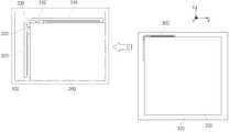
도 1은 본 발명의 일 실시예에 따른 MIMO 안테나 장치의 구조를 나타낸 도면이다.1 is a diagram illustrating a structure of a MIMO antenna apparatus according to an embodiment of the present invention.
도 1을 참조하면, 본 MIMO(Multiple Input Multiple Output) 안테나 장치는 기판(100), 접지면(200), 및 적어도 하나의 안테나부(300)를 포함한다.Referring to FIG. 1, the present Multiple Input Multiple Output (MIMO) antenna apparatus includes a
기판(100)의 상부에 기판(100)보다 작은 크기로 접지면(200)이 배치된다. 또한, 기판(100)의 상부에 접지면(200)이 배치되지 않은 부분에서 접지면(200)의 모 서리 영역에 대응하는 위치에 안테나부(300)가 배치된다.A
안테나부(300)는 한 쌍의 안테나 소자(310, 320) 및 한 쌍의 안테나 소자(310, 320)를 연결하는 연결부(330)를 포함한다. 안테나부(300)는 서로 직접적으로 연결되는 한 쌍의 안테나 소자(310, 320)를 포함하여 기판(100) 상에 적어도 하나 이상이 배치될 수 있다.The
본 실시예에서는 설명의 편의상, 한 쌍의 안테나 소자(310, 320) 중 도면상에서 수평 방향으로 설치된 안테나 소자를 제1 안테나 소자(310)라 하고, 수직 방향으로 설치된 안테나 소자를 제2 안테나 소자(320)라 한다.In the present embodiment, for convenience of explanation, an antenna element provided in the horizontal direction on the drawing among the pair of
제1 및 제2 안테나 소자(310, 320)의 일단에는 각각 급전을 위한 급전부(Feeding point)(312, 322)가 형성되고, 타단은 각각 접지면(200)과 연결된다. 제1 및 제2 안테나 소자(310, 320)는 스트립(Strip) 형상의 몸체가 중간 부분에서 절곡되어 두개의 스트립이 평행을 이루는 루프(Loop) 형상일 수 있다. 제1 및 제2 안테나 소자(310, 320)의 몸체는 'ㄷ'자 형상일 수 있으나, 제1 및 제2 안테나 소자(310, 320)가 접지면(200)과 연결됨에 따라 루프 형상을 형성할 수 있다.
제1 및 제2 안테나 소자(310, 320)의 전체 길이는 사용 주파수에 대하여 1 파장의 길이를 갖는다. 본 실시예에서, 제1 및 제2 안테나 소자(310, 320)의 몸체가 중간 부분에서 절곡되어 루프 형상을 형성함으로써, 제한된 공간에서 안테나 소자의 길이를 더 크게 할 수 있다.The total length of the first and
제1 및 제2 안테나 소자(310, 320)의 일단에 각각 형성되는 급전부(312, 322)는 접지면(200)을 향하는 방향으로 돌출 형성될 수 있으며, 제1 및 제2 안테나 소자(310, 320)의 타단도 접지면(200)을 향하는 방향으로 돌출되어 접지면(200)에 연결된다.The
연결부(330)는 제1 및 제2 안테나 소자(310, 320)의 급전부(312, 322)가 형성된 일단이 서로 인접하고, 소정 각도를 이루도록 제1 및 제2 안테나 소자(310, 320)를 연결한다. 제1 및 제2 안테나 소자(310, 320)와 연결부(330)는 일체로 형성될 수 있다.The
또한, 연결부(330)는 제1 및 제2 안테나 소자(310, 320)가 직각을 이루도록 연결하는 것이 바람직하다. 즉, 제1 및 제2 안테나 소자(310, 320)는 90도를 이루도록 배치된 상태에서 연결부(330)에 의해 연결될 수 있다. 여기서, 제1 및 제2 안테나 소자(310, 320)가 이루는 각도는 반드시 90도에 한정되지 않고 변형이 가능하다. 다만, 제1 및 제2 안테나 소자(310, 320)가 직각을 이룰 때, 상호 간섭을 가장 효과적으로 저하시킬 수 있다.Also, it is preferable that the
연결부(330)를 통해 연결된 제1 및 제2 안테나 소자(310, 320)는 접지면(200)의 모서리 영역에 대응하게 설치된다. 보다 구체적으로, 접지면(200)의 어느 하나의 모서리로부터 형성되는 두 변과 각각 평행을 이루는 방향으로 제1 및 제2 안테나 소자(310, 320)가 배치된다. 즉, 하나의 안테나부(300)가 접지면(200)의 어느 하나의 모서리 영역을 둘러싸는 형태로 설치된다.The first and
도 1에서는 하나의 안테나부(300)가 설치된 것을 예시하였으나, 사각형 형태의 기판(100) 및 접지면(200)에 안테나부(300)가 설치될 경우, 4개의 모서리 영역에 4개의 안테나부(300)가 설치될 수 있다.1, it is assumed that one
제1 및 제2 안테나 소자(310, 320)에 동시에 급전이 이루어질 경우, 하나의 안테나 소자(310 혹은 320)의 전계가 최고가 되는 지점에서 다른 안테나 소자(310 혹은 320)의 전계는 최소가 된다. 따라서, 제1 및 제2 안테나 소자(310, 320)는 전기적으로 분리되어 있는 것처럼 동작할 수 있으며, 상호 간섭이 발생하지 않는다.When the first and
도 1에서는 안테나부(300)가 기판(100)의 상부에 접지면(200)과 평행하게 배치된 것을 예시하였으나, 이는 반드시 여기에 한정되지 않는다. 일 예로, 안테나부(300)는 접지면(200)의 상부 모서리 영역에 배치될 수도 있다.1, the
제1 및 제2 안테나 소자(310, 320)는 동시에 급전이 이루어질 수 있다. 혹은 제1 및 제2 안테나 소자(310, 320) 중 어느 하나에만 선택적으로 급전이 이루어질 수도 있다.The first and
제1 및 제2 안테나 소자(310, 320)에 동시에 급전이 이루어졌을 경우의 전계 분포를 살펴보면, 제1 안테나 소자(310)의 전계가 최대일 경우 제2 안테나 소자(320)의 전계는 최소가 된다. 또한, 제2 안테나 소자(320)의 전계가 최대일 경우, 제1 안테나 소자(310)의 전계는 최대가 된다. 이에 의해, 제1 및 제2 안테나 소자(310, 320) 간의 결합이 최소가 된다.The electric field distribution of the
또한, 제1 및 제2 안테나 소자(310, 320)에는 전계 분포가 형성되나, 접지면(200)에는 전계 분포가 형성되지 않는다. 이는 접지면(200)의 크기 변화에 안테나 특성이 영향을 받지 않음을 의미한다. 즉, MIMO 안테나 장치가 적용될 단말기의 종류에 따라 자유롭게 접지면(200)의 형태의 변경이 용이한 이점을 갖는다.An electric field distribution is formed on the first and
안테나부(300) 중 하나의 안테나 소자(310 혹은 320)에만 급전이 이루어졌을 경우의 전계 분포를 살펴보면, 제1 및 제2 안테나 소자(310, 320) 모두에 전계 분포가 형성된다. 다만, 급전이 이루어진 하나의 안테나 소자(310 혹은 320)에 먼저 전계 분포가 나타나고 90도의 위상차로 다른 안테나 소자(310 혹은 320)에 전계 분포가 나타난다.An electric field distribution is formed in both of the first and
도 2a 및 도 2b는 안테나부의 방사 패턴을 나타낸 도면이다.2A and 2B are views showing radiation patterns of the antenna unit.
도 2a는 제1 안테나 소자(310)의 급전부(312)를 통해서만 급전이 이루어졌을 경우의 방사 패턴을 나타낸 것이다. 도시한 바와 같이, 제1 안테나 소자(310)의 방사 패턴은 x축 방향으로 형성된다.2A shows a radiation pattern when feeding is performed only through the
도 2b는 제2 안테나 소자(320)의 급전부(322)를 통해서만 급전이 이루어졌을 경우의 방사 패턴을 나타낸 것이다. 도시한 바와 같이, 제2 안테나 소자(320)의 방사 패턴은 y축 방향으로 형성된다.2B shows a radiation pattern when feeding is performed only through the feeding
이와 같이, 제1 안테나 소자(310)의 방사 패턴과 제2 안테나 소자(320)의 방사 패턴이 서로 반대 방향으로 형성되는 것을 알 수 있다. 일반적으로, MIMO 안테나 시스템에서 각 안테나 소자들은 방사 패턴이 결합하여 상호 간섭을 일으키게 되나, 본 실시예에서는 제1 및 제2 안테나 소자(310, 320)가 상호 직각 방향의 방사 패턴을 나타내므로, 방사 패턴에 의한 결합이 최소화된다.Thus, it can be seen that the radiation pattern of the
본 발명의 일 실시예에 따른 MIMO 안테나 장치의 주파수 응답 특성을 나타내기 위하여, S-파라미터를 측정해 볼 수 있다. 이때 사용되는 S-파라미터를 살펴보면, S11은 입출력 포트가 1일 때의 반사 손실(return loss)을 의미하는 것으로, 제1 안테나 소자(310)의 반사 특성을 나타낸다. 이와 마찬가지로, S22는 입출력 포트 가 2일 때의 반사 손실을 의미하는 것이므로, 제2 안테나 소자(320)의 반사 특성을 나타낸다. S12 및 S21은 포트 상호간의 결합을 의미한다. 여기서, S21의 경우 2번 포트로 신호를 입력하였을 경우 1번 포트에서 측정된 양으로, 어느 정도의 신호가 1번 포트로 들어갔는지를 나타내는 양이다. 일반적으로, 수동 소자의 경우에는 S12 및 S21이 동일한 값을 가지며, MIMO 안테나의 경우에는 S11, S22, S12, S21가 공진 주파수에서 낮을수록 좋은 특성을 갖는다.In order to show the frequency response characteristic of the MIMO antenna apparatus according to an embodiment of the present invention, the S-parameter can be measured. In this case, S11 denotes a return loss when the input / output port is 1, and represents the reflection characteristic of the
본 발명의 일 실시예에 따른 MIMO 안테나 장치는 제1 및 제2 안테나 소자(310, 320)가 직접 연결되었음에도 불구하고, S21이 중심 주파수 대역에서 -20dB 정도로 현저히 낮게 나타난다. 즉, S21이 현저히 낮게 나타나므로 좋은 특성을 갖는다는 의미이다.Although the first and
본 발명의 일 실시예에 따른 MIMO 안테나 장치의 상호 간섭 상태를 파악하기 위하여, 본 MIMO 안테나 장치의 코릴레이션 계수(Correlation coefficient)를 방사 패턴과 S-파라미터를 이용하여 각각 도출하여 볼 수 있다.In order to grasp the mutual interference state of the MIMO antenna apparatus according to an embodiment of the present invention, the correlation coefficient of the present MIMO antenna apparatus can be derived and observed using a radiation pattern and an S-parameter.
안테나의 중심 주파수 대역에서 방사 패턴 및 S-파라미터를 이용하여 도출한 코릴레이션 계수는 각각 0에 근사한 값을 나타낸다. 즉, 제1 및 제2 안테나 소자(310, 320)간의 상호 간섭이 거의 나타나지 않는다는 의미이다.The correlation coefficients derived using the radiation pattern and the S-parameter in the center frequency band of the antenna each have a value close to zero. That is, mutual interference between the first and
도 3a 및 도 3b는 본 발명의 다른 실시예에 따른 MIMO 안테나 장치의 구조를 나타낸 도면이다.3A and 3B are views illustrating a structure of a MIMO antenna apparatus according to another embodiment of the present invention.
도 3a는 본 MIMO 안테나 장치에 2개의 안테나부(300)를 배치한 예를 도시한 것이다. 기판(100) 및 접지면(200)의 상부 두 모서리 영역에 각각 안테나부(300)를 설치하였다. 이에 따라, 두개의 안테나부(300)는 서로 대칭하는 형태로 구비된다.3A shows an example in which two
본 실시예에서는 설명의 편의상, 도면의 좌측으로부터 순차적으로 1번 안테나 소자(#1), 2번 안테나 소자(#2), 3번 안테나 소자(#3), 및 4번 안테나 소자(#4)라 칭한다.In this embodiment, the antenna elements # 1, # 2, # 3, # 4, and # 4 are sequentially arranged from the left side of the drawing for convenience of explanation. Quot;
MIMO 안테나 장치에서는 두개의 안테나부(300) 즉, 4개의 안테나 소자(#1 내지 #4)를 모두 동작시키는 것이 일반적이나, 한 쌍의 안테나 소자(310, 320) 중 하나에 급전이 이루어지도록 급전부(312, 322)의 급전을 스위칭하는 스위칭부(400)를 구비함으로써, 4개의 안테나 소자(#1 내지 #4) 중 2개의 안테나 소자가 동작하도록 구성할 수 있다.The MIMO antenna apparatus generally operates all of the two
이때, 첫번째 안테나부(300) 중 강한 전계강도를 나타내는 하나의 안테나 소자(#1 혹은 #2) 및 두번째 안테나부(300) 중 강한 전계강도를 나타내는 하나의 안테나 소자(#3 혹은 #4)가 동작하도록 구성하는 것이 바람직하다.At this time, one antenna element (# 1 or # 2) showing strong electric field intensity and the other antenna element (# 3 or # 4) showing strong electric field intensity of the
도 3b는 본 MIMO 안테나 장치에 4개의 안테나부(300)를 배치한 예를 도시한 것이다. 기판(100) 및 접지면(200)은 사각형 형상으로 총 4개의 모서리 영역이 존재함에 따라, 최대 4개의 안테나부(300)를 설치할 수 있다.FIG. 3B shows an example in which four
앞에서도 언급한 바와 같이, MIMO 안테나 장치에서는 모든 안테나 소자를 동작시키는 것이 일반적이나, 4개의 안테나부(300) 즉, 8개의 안테나 소자 중 각각 선택된 4개의 안테나 소자가 동작하도록 구성할 수 있다.As described above, in the MIMO antenna apparatus, it is common to operate all the antenna elements, but it is possible to configure the four
즉, 첫번째 안테나부(300) 중 강한 전계강도를 나타내는 하나의 안테나 소자, 두번째 안테나부(300) 중 강한 전계강도를 나타내는 하나의 안테나 소자, 세번 째 안테나부(300) 중 강한 전계강도를 나타내는 하나의 안테나 소자, 및 네번째 안테나부(300) 중 강한 전계강도를 나타내는 하나의 안테나 소자가 동작하도록 구성하는 것이 바람직하다. 도 3b에는 스위칭부(400)를 도시하지 않았으나, 도 3a에 예시한 것과 같이 스위칭부(400)가 구비될 수 있다.That is, one antenna element showing strong electric field intensity among the
도 3a에 도시한 2개의 안테나부(300)는 2-MIMO로 동작할 수 있다. 1번과 3번 안테나 소자(#1 및 #3), 1번과 4번 안테나 소자(#1 및 #4), 2번과 3번 안테나 소자(#2 및 #3), 및 2번과 4번 안테나 소자(#2 및 #4)의 조합으로 사용이 가능하다. 도 3b와 같이 4개의 안테나부(300)가 구성된 경우, 4-MIMO로 동작할 수 있다. 이 경우, 각 안테나부(300)는 MIMO 다이버시티 안테나로 활용이 가능하다.The two
이상에서는 본 발명의 바람직한 실시예에 대하여 도시하고 설명하였지만, 본 발명은 상술한 특정의 실시예에 한정되지 아니하며, 청구범위에서 청구하는 본 발명의 요지를 벗어남이 없이 당해 발명이 속하는 기술분야에서 통상의 지식을 가진자에 의해 다양한 변형실시가 가능한 것은 물론이고, 이러한 변형 실시예들은 본 발명의 기술적 사상이나 전망으로부터 개별적으로 이해되어서는 안될 것이다.While the present invention has been particularly shown and described with reference to exemplary embodiments thereof, it is clearly understood that the same is by way of illustration and example only and is not to be construed as limiting the scope of the invention as defined by the appended claims. It will be understood by those skilled in the art that various changes in form and details may be made therein without departing from the spirit and scope of the invention.
도 1은 본 발명의 일 실시예에 따른 MIMO 안테나 장치의 구조를 나타낸 도면,FIG. 1 illustrates a structure of a MIMO antenna apparatus according to an embodiment of the present invention. FIG.
도 2a 및 도 2b는 안테나부의 방사 패턴을 나타낸 도면, 그리고,2A and 2B are diagrams showing a radiation pattern of the antenna unit,
도 3a 및 도 3b는 본 발명의 다른 실시예에 따른 MIMO 안테나 장치의 구조를 나타낸 도면이다.3A and 3B are views illustrating a structure of a MIMO antenna apparatus according to another embodiment of the present invention.
* 도면의 주요부분에 대한 부호의 설명 *Description of the Related Art [0002]
100 : 기판 200 : 접지면100: substrate 200: ground plane
300 : 안테나부 310, 320 : 안테나 소자300:
312, 322 : 급전부 330 : 연결부312, 322: power feeder 330:
Claims (6)
Translated fromKoreanPriority Applications (7)
| Application Number | Priority Date | Filing Date | Title |
|---|---|---|---|
| KR1020070104549AKR101464510B1 (en) | 2007-10-17 | 2007-10-17 | MIMO antenna apparatus |
| US12/112,033US8164525B2 (en) | 2007-10-17 | 2008-04-30 | MIMO antenna and communication device using the same |
| EP18191370.8AEP3425727B1 (en) | 2007-10-17 | 2008-07-17 | Mimo antenna and communication device using the same |
| EP08160630.3AEP2053692B1 (en) | 2007-10-17 | 2008-07-17 | Mimo antenna and communication device using the same |
| JP2008187830AJP5424589B2 (en) | 2007-10-17 | 2008-07-18 | MIMO antenna device |
| US13/426,032US8547282B2 (en) | 2007-10-17 | 2012-03-21 | MIMO antenna and communication device using the same |
| JP2013188269AJP5752198B2 (en) | 2007-10-17 | 2013-09-11 | MIMO antenna device |
Applications Claiming Priority (1)
| Application Number | Priority Date | Filing Date | Title |
|---|---|---|---|
| KR1020070104549AKR101464510B1 (en) | 2007-10-17 | 2007-10-17 | MIMO antenna apparatus |
Publications (2)
| Publication Number | Publication Date |
|---|---|
| KR20090039103A KR20090039103A (en) | 2009-04-22 |
| KR101464510B1true KR101464510B1 (en) | 2014-11-26 |
Family
ID=40329171
Family Applications (1)
| Application Number | Title | Priority Date | Filing Date |
|---|---|---|---|
| KR1020070104549AExpired - Fee RelatedKR101464510B1 (en) | 2007-10-17 | 2007-10-17 | MIMO antenna apparatus |
Country Status (4)
| Country | Link |
|---|---|
| US (2) | US8164525B2 (en) |
| EP (2) | EP2053692B1 (en) |
| JP (2) | JP5424589B2 (en) |
| KR (1) | KR101464510B1 (en) |
Cited By (1)
| Publication number | Priority date | Publication date | Assignee | Title |
|---|---|---|---|---|
| CN108539381A (en)* | 2018-05-11 | 2018-09-14 | 瑞声科技(南京)有限公司 | Antenna system and mobile terminal |
Families Citing this family (33)
| Publication number | Priority date | Publication date | Assignee | Title |
|---|---|---|---|---|
| JP3441340B2 (en)* | 1997-07-28 | 2003-09-02 | 京セラ株式会社 | Method for manufacturing semiconductor device |
| KR101638798B1 (en)* | 2010-01-21 | 2016-07-13 | 삼성전자주식회사 | Apparatus for multiple antennas in wireless communication system |
| KR101102650B1 (en)* | 2010-04-28 | 2012-01-04 | 서울과학기술대학교 산학협력단 | MIO antennas for improved isolation |
| US8947318B2 (en)* | 2011-04-22 | 2015-02-03 | Sony Mobile Communications Inc. | Antenna apparatus |
| KR20130085707A (en)* | 2012-01-20 | 2013-07-30 | 엘지전자 주식회사 | Mobile terminal |
| JP5919921B2 (en)* | 2012-03-19 | 2016-05-18 | 富士通株式会社 | ANTENNA DEVICE AND ELECTRONIC DEVICE |
| CN104919655B (en)* | 2013-01-10 | 2018-11-20 | Agc株式会社 | MIMO antenna and wireless device |
| US20150372383A1 (en)* | 2013-02-18 | 2015-12-24 | Nec Corporation | Dual band antenna device |
| CN104253310B (en)* | 2013-06-28 | 2018-06-26 | 华为技术有限公司 | Multiaerial system and mobile terminal |
| GB2516304A (en)* | 2013-07-19 | 2015-01-21 | Nokia Corp | Apparatus and methods for wireless communication |
| US10276941B2 (en)* | 2014-01-20 | 2019-04-30 | Qorvo Us, Inc. | Multiple-input multiple-output RF antenna architectures |
| CN105981216B (en)* | 2014-02-11 | 2019-08-06 | 瑞典爱立信有限公司 | User terminal equipment for interference-limited scenarios |
| TWI539663B (en)* | 2014-03-19 | 2016-06-21 | 宏碁股份有限公司 | Handheld device |
| US20150364820A1 (en)* | 2014-06-13 | 2015-12-17 | Qualcomm Incorporated | Multiband antenna apparatus and methods |
| GB2528839B (en)* | 2014-07-25 | 2019-04-03 | Kathrein Werke Kg | Multiband antenna |
| GB2529884B (en) | 2014-09-05 | 2017-09-13 | Smart Antenna Tech Ltd | Reconfigurable multi-band antenna with independent control |
| GB2529885B (en)* | 2014-09-05 | 2017-10-04 | Smart Antenna Tech Ltd | Multiple antenna system arranged in the periphery of a device casing |
| US10535921B2 (en) | 2014-09-05 | 2020-01-14 | Smart Antenna Technologies Ltd. | Reconfigurable multi-band antenna with four to ten ports |
| US10211526B2 (en)* | 2014-09-25 | 2019-02-19 | Texas Instruments Incorporated | PCB beam-forming antenna |
| EP3035547B1 (en) | 2014-12-16 | 2019-11-20 | Nokia Technologies Oy | An apparatus and method for multiple antenna systems |
| WO2016138650A1 (en)* | 2015-03-04 | 2016-09-09 | Huawei Technologies Co.,Ltd. | Multiple input multiple output wireless antenna structures and communication device |
| CN108110417B (en)* | 2015-10-19 | 2020-03-10 | Oppo广东移动通信有限公司 | LTE-A MIMO antenna device with all-metal shell |
| CN105680177B (en)* | 2016-01-22 | 2018-04-06 | 西北工业大学 | T-type structure feed double frequency is applied to WLAN two unit planar microstrip mimo antennas |
| CN106340708A (en)* | 2016-09-30 | 2017-01-18 | 努比亚技术有限公司 | Antenna structure and electronic device |
| CN108736148B (en)* | 2017-04-17 | 2020-01-31 | 华为技术有限公司 | Antenna devices and electronic equipment |
| CN107454214B (en)* | 2017-07-21 | 2020-07-21 | 北京小米移动软件有限公司 | Antenna structure of terminal device, control method, device and storage medium |
| KR102424681B1 (en) | 2017-11-27 | 2022-07-25 | 삼성전자주식회사 | Arrangement structure for 5g communication device and electronic device including the same |
| WO2019136255A1 (en)* | 2018-01-05 | 2019-07-11 | Wispry, Inc. | Corner antenna array devices systems, and methods |
| KR102028352B1 (en) | 2018-01-16 | 2019-10-04 | 포항공과대학교 산학협력단 | An apparatus of antenna and mobile device thereof |
| CN108808228B (en)* | 2018-08-23 | 2021-01-22 | 维沃移动通信有限公司 | Antenna system and electronic equipment |
| US11303042B2 (en)* | 2019-05-23 | 2022-04-12 | Htc Corporation | Communication device |
| KR102093326B1 (en) | 2019-09-20 | 2020-03-25 | 포항공과대학교 산학협력단 | An apparatus of antenna and mobile device thereof |
| CN113036401A (en)* | 2019-12-24 | 2021-06-25 | 中兴通讯股份有限公司 | Half-wave oscillator, half-wave oscillator component and antenna |
Citations (2)
| Publication number | Priority date | Publication date | Assignee | Title |
|---|---|---|---|---|
| KR20060047567A (en)* | 2004-04-28 | 2006-05-18 | 샤프 가부시키가이샤 | Antenna device, antenna system and broadcast receiving device |
| JP2007215133A (en)* | 2006-02-13 | 2007-08-23 | Ntt Docomo Inc | Dipole antenna and multi-antenna device |
Family Cites Families (27)
| Publication number | Priority date | Publication date | Assignee | Title |
|---|---|---|---|---|
| US2541021A (en)* | 1945-06-04 | 1951-02-13 | Standard Telephones Cables Ltd | Antenna |
| US3050730A (en)* | 1959-07-09 | 1962-08-21 | Sylvania Electric Prod | Broadband plate antenna |
| US4750000A (en)* | 1987-09-16 | 1988-06-07 | Schroeder Klaus G | Ultra-broadband impedance matched electrically small self-complementary signal radiating structures with impedance-inverting feed for complementary pairs using thin wire elements |
| JPH0744492B2 (en)* | 1988-06-15 | 1995-05-15 | 松下電工株式会社 | Polarization diversity wireless communication system |
| GB9309368D0 (en) | 1993-05-06 | 1993-06-16 | Ncr Int Inc | Antenna apparatus |
| JPH09260925A (en) | 1996-03-19 | 1997-10-03 | Matsushita Electric Ind Co Ltd | Antenna device |
| JP3252786B2 (en)* | 1998-02-24 | 2002-02-04 | 株式会社村田製作所 | Antenna device and wireless device using the same |
| JP2001053544A (en)* | 1999-08-11 | 2001-02-23 | Mitsubishi Electric Corp | Antenna integrated amplifier module |
| JP4263820B2 (en)* | 1999-10-21 | 2009-05-13 | 株式会社ヨコオ | Flat antenna for circular polarization |
| US6542128B1 (en)* | 2000-03-31 | 2003-04-01 | Tyco Electronics Logistics Ag | Wide beamwidth ultra-compact antenna with multiple polarization |
| US6426723B1 (en) | 2001-01-19 | 2002-07-30 | Nortel Networks Limited | Antenna arrangement for multiple input multiple output communications systems |
| US6483463B2 (en) | 2001-03-27 | 2002-11-19 | Centurion Wireless Technologies, Inc. | Diversity antenna system including two planar inverted F antennas |
| US6686886B2 (en) | 2001-05-29 | 2004-02-03 | International Business Machines Corporation | Integrated antenna for laptop applications |
| US7339531B2 (en) | 2001-06-26 | 2008-03-04 | Ethertronics, Inc. | Multi frequency magnetic dipole antenna structures and method of reusing the volume of an antenna |
| WO2004084344A1 (en) | 2003-03-18 | 2004-09-30 | Sony Ericsson Mobile Communications Ab | Compact diversity antenna |
| JP4152840B2 (en) | 2003-09-11 | 2008-09-17 | 太陽誘電株式会社 | Communication device |
| JP4082341B2 (en)* | 2003-12-02 | 2008-04-30 | トヨタ自動車株式会社 | Antenna device |
| JP3805772B2 (en) | 2004-01-13 | 2006-08-09 | 株式会社東芝 | ANTENNA DEVICE AND PORTABLE RADIO COMMUNICATION DEVICE |
| KR20050112272A (en) | 2004-05-25 | 2005-11-30 | 기아자동차주식회사 | Device for heating a stretcher for ambulance |
| JP2005354501A (en)* | 2004-06-11 | 2005-12-22 | Matsushita Electric Ind Co Ltd | Portable wireless terminal |
| JP2007013643A (en)* | 2005-06-30 | 2007-01-18 | Lenovo Singapore Pte Ltd | Integrally formed flat-plate multi-element antenna and electronic apparatus |
| FR2888675A1 (en)* | 2005-07-13 | 2007-01-19 | Thomson Licensing Sas Soc Par | 2-D DIVERSITY ANTENNA SYSTEM AND CARD FOR WIRELESS COMMUNICATION APPARATUS PROVIDED WITH SUCH A SYSTEM |
| JP4451407B2 (en)* | 2005-07-22 | 2010-04-14 | 太平洋工業株式会社 | Bidirectional constant pressure expansion valve |
| JP2007074446A (en)* | 2005-09-07 | 2007-03-22 | Toshiba Corp | Portable information device with built-in wireless communication antenna |
| JP2007235762A (en) | 2006-03-02 | 2007-09-13 | Fujitsu Ltd | Antenna device for multi-input multi-output communication |
| JP4224081B2 (en)* | 2006-06-12 | 2009-02-12 | 株式会社東芝 | Circularly polarized antenna device |
| US7477201B1 (en)* | 2007-08-30 | 2009-01-13 | Motorola, Inc. | Low profile antenna pair system and method |
- 2007
- 2007-10-17KRKR1020070104549Apatent/KR101464510B1/ennot_activeExpired - Fee Related
- 2008
- 2008-04-30USUS12/112,033patent/US8164525B2/enactiveActive
- 2008-07-17EPEP08160630.3Apatent/EP2053692B1/ennot_activeCeased
- 2008-07-17EPEP18191370.8Apatent/EP3425727B1/enactiveActive
- 2008-07-18JPJP2008187830Apatent/JP5424589B2/ennot_activeExpired - Fee Related
- 2012
- 2012-03-21USUS13/426,032patent/US8547282B2/enactiveActive
- 2013
- 2013-09-11JPJP2013188269Apatent/JP5752198B2/enactiveActive
Patent Citations (2)
| Publication number | Priority date | Publication date | Assignee | Title |
|---|---|---|---|---|
| KR20060047567A (en)* | 2004-04-28 | 2006-05-18 | 샤프 가부시키가이샤 | Antenna device, antenna system and broadcast receiving device |
| JP2007215133A (en)* | 2006-02-13 | 2007-08-23 | Ntt Docomo Inc | Dipole antenna and multi-antenna device |
Cited By (1)
| Publication number | Priority date | Publication date | Assignee | Title |
|---|---|---|---|---|
| CN108539381A (en)* | 2018-05-11 | 2018-09-14 | 瑞声科技(南京)有限公司 | Antenna system and mobile terminal |
Also Published As
| Publication number | Publication date |
|---|---|
| EP2053692B1 (en) | 2018-09-05 |
| EP3425727A1 (en) | 2019-01-09 |
| US8547282B2 (en) | 2013-10-01 |
| US20130050052A1 (en) | 2013-02-28 |
| US8164525B2 (en) | 2012-04-24 |
| KR20090039103A (en) | 2009-04-22 |
| US20090102742A1 (en) | 2009-04-23 |
| EP2053692A3 (en) | 2010-03-17 |
| JP5424589B2 (en) | 2014-02-26 |
| EP3425727B1 (en) | 2020-07-08 |
| JP5752198B2 (en) | 2015-07-22 |
| EP2053692A2 (en) | 2009-04-29 |
| JP2014039281A (en) | 2014-02-27 |
| JP2009100444A (en) | 2009-05-07 |
Similar Documents
| Publication | Publication Date | Title |
|---|---|---|
| KR101464510B1 (en) | MIMO antenna apparatus | |
| US8514134B2 (en) | MIMO antenna having parasitic elements | |
| KR101166089B1 (en) | Multi band mimo antenna | |
| JP6737486B2 (en) | Antenna module, MIMO antenna, and terminal | |
| US8441408B2 (en) | Miniaturized multiple input multiple output (MIMO) antenna | |
| US9444129B2 (en) | Multi-band compatible multi-antenna device and communication equipment | |
| KR101169932B1 (en) | Multi band mimo antenna | |
| JP5631921B2 (en) | Multi-antenna and electronic device | |
| KR100842082B1 (en) | Antenna with additional ground | |
| JP2006352871A (en) | Planar MIMO array antenna including isolation element | |
| CN101715617A (en) | Wireless network device including polarization and space diversity antenna system | |
| US20130285865A1 (en) | Printed slot-type directional antenna, and system comprising an array of a plurality of printed slot-type directional antennas | |
| US9350075B2 (en) | Branched multiport antennas | |
| KR20100022374A (en) | An antenna apparatus | |
| CN107623176A (en) | terminal MIMO antenna system | |
| KR20120037763A (en) | Multi band mimo antenna | |
| US7019709B2 (en) | Antenna device | |
| KR20220158009A (en) | Antennas, antenna modules, and wireless network devices | |
| JP6289077B2 (en) | Antenna device | |
| JP6917588B2 (en) | 3 distributor | |
| CN118160151A (en) | Antenna unit, antenna and antenna feed system | |
| JP2012049783A (en) | L shaped folding monopole antenna device | |
| JP2006246228A (en) | ANTENNA DEVICE AND WIRELESS COMMUNICATION SYSTEM |
Legal Events
| Date | Code | Title | Description |
|---|---|---|---|
| PA0109 | Patent application | St.27 status event code:A-0-1-A10-A12-nap-PA0109 | |
| P11-X000 | Amendment of application requested | St.27 status event code:A-2-2-P10-P11-nap-X000 | |
| P13-X000 | Application amended | St.27 status event code:A-2-2-P10-P13-nap-X000 | |
| R15-X000 | Change to inventor requested | St.27 status event code:A-3-3-R10-R15-oth-X000 | |
| R16-X000 | Change to inventor recorded | St.27 status event code:A-3-3-R10-R16-oth-X000 | |
| PG1501 | Laying open of application | St.27 status event code:A-1-1-Q10-Q12-nap-PG1501 | |
| R18-X000 | Changes to party contact information recorded | St.27 status event code:A-3-3-R10-R18-oth-X000 | |
| A201 | Request for examination | ||
| PA0201 | Request for examination | St.27 status event code:A-1-2-D10-D11-exm-PA0201 | |
| D13-X000 | Search requested | St.27 status event code:A-1-2-D10-D13-srh-X000 | |
| D14-X000 | Search report completed | St.27 status event code:A-1-2-D10-D14-srh-X000 | |
| E902 | Notification of reason for refusal | ||
| PE0902 | Notice of grounds for rejection | St.27 status event code:A-1-2-D10-D21-exm-PE0902 | |
| AMND | Amendment | ||
| P11-X000 | Amendment of application requested | St.27 status event code:A-2-2-P10-P11-nap-X000 | |
| P13-X000 | Application amended | St.27 status event code:A-2-2-P10-P13-nap-X000 | |
| E601 | Decision to refuse application | ||
| PE0601 | Decision on rejection of patent | St.27 status event code:N-2-6-B10-B15-exm-PE0601 | |
| T11-X000 | Administrative time limit extension requested | St.27 status event code:U-3-3-T10-T11-oth-X000 | |
| PJ0201 | Trial against decision of rejection | St.27 status event code:A-3-3-V10-V11-apl-PJ0201 | |
| AMND | Amendment | ||
| E13-X000 | Pre-grant limitation requested | St.27 status event code:A-2-3-E10-E13-lim-X000 | |
| P11-X000 | Amendment of application requested | St.27 status event code:A-2-2-P10-P11-nap-X000 | |
| P13-X000 | Application amended | St.27 status event code:A-2-2-P10-P13-nap-X000 | |
| PB0901 | Examination by re-examination before a trial | St.27 status event code:A-6-3-E10-E12-rex-PB0901 | |
| B701 | Decision to grant | ||
| PB0701 | Decision of registration after re-examination before a trial | St.27 status event code:A-3-4-F10-F13-rex-PB0701 | |
| GRNT | Written decision to grant | ||
| PR0701 | Registration of establishment | St.27 status event code:A-2-4-F10-F11-exm-PR0701 | |
| PR1002 | Payment of registration fee | St.27 status event code:A-2-2-U10-U11-oth-PR1002 Fee payment year number:1 | |
| PG1601 | Publication of registration | St.27 status event code:A-4-4-Q10-Q13-nap-PG1601 | |
| P22-X000 | Classification modified | St.27 status event code:A-4-4-P10-P22-nap-X000 | |
| FPAY | Annual fee payment | Payment date:20171030 Year of fee payment:4 | |
| PR1001 | Payment of annual fee | St.27 status event code:A-4-4-U10-U11-oth-PR1001 Fee payment year number:4 | |
| FPAY | Annual fee payment | Payment date:20181030 Year of fee payment:5 | |
| PR1001 | Payment of annual fee | St.27 status event code:A-4-4-U10-U11-oth-PR1001 Fee payment year number:5 | |
| PR1001 | Payment of annual fee | St.27 status event code:A-4-4-U10-U11-oth-PR1001 Fee payment year number:6 | |
| PR1001 | Payment of annual fee | St.27 status event code:A-4-4-U10-U11-oth-PR1001 Fee payment year number:7 | |
| PR1001 | Payment of annual fee | St.27 status event code:A-4-4-U10-U11-oth-PR1001 Fee payment year number:8 | |
| PR1001 | Payment of annual fee | St.27 status event code:A-4-4-U10-U11-oth-PR1001 Fee payment year number:9 | |
| PC1903 | Unpaid annual fee | St.27 status event code:A-4-4-U10-U13-oth-PC1903 Not in force date:20231119 Payment event data comment text:Termination Category : DEFAULT_OF_REGISTRATION_FEE | |
| PC1903 | Unpaid annual fee | St.27 status event code:N-4-6-H10-H13-oth-PC1903 Ip right cessation event data comment text:Termination Category : DEFAULT_OF_REGISTRATION_FEE Not in force date:20231119 |