KR101464083B1 - Ac direct connection type LED driving circuit having function of flicker reduction - Google Patents
Ac direct connection type LED driving circuit having function of flicker reductionDownload PDFInfo
- Publication number
- KR101464083B1 KR101464083B1KR20130083941AKR20130083941AKR101464083B1KR 101464083 B1KR101464083 B1KR 101464083B1KR 20130083941 AKR20130083941 AKR 20130083941AKR 20130083941 AKR20130083941 AKR 20130083941AKR 101464083 B1KR101464083 B1KR 101464083B1
- Authority
- KR
- South Korea
- Prior art keywords
- led
- led illumination
- driving circuit
- unit
- leds
- Prior art date
- Legal status (The legal status is an assumption and is not a legal conclusion. Google has not performed a legal analysis and makes no representation as to the accuracy of the status listed.)
- Active
Links
Images


Classifications
- H—ELECTRICITY
- H05—ELECTRIC TECHNIQUES NOT OTHERWISE PROVIDED FOR
- H05B—ELECTRIC HEATING; ELECTRIC LIGHT SOURCES NOT OTHERWISE PROVIDED FOR; CIRCUIT ARRANGEMENTS FOR ELECTRIC LIGHT SOURCES, IN GENERAL
- H05B45/00—Circuit arrangements for operating light-emitting diodes [LED]
- H05B45/30—Driver circuits
- H05B45/37—Converter circuits
- H—ELECTRICITY
- H05—ELECTRIC TECHNIQUES NOT OTHERWISE PROVIDED FOR
- H05B—ELECTRIC HEATING; ELECTRIC LIGHT SOURCES NOT OTHERWISE PROVIDED FOR; CIRCUIT ARRANGEMENTS FOR ELECTRIC LIGHT SOURCES, IN GENERAL
- H05B45/00—Circuit arrangements for operating light-emitting diodes [LED]
- H05B45/40—Details of LED load circuits
- H05B45/44—Details of LED load circuits with an active control inside an LED matrix
- H05B45/46—Details of LED load circuits with an active control inside an LED matrix having LEDs disposed in parallel lines
Landscapes
- Circuit Arrangement For Electric Light Sources In General (AREA)
Abstract
Translated fromKorean
Description
Translated fromKorean본 발명은 교류 다이렉트 방식의 LED 구동회로에 관한 것으로서, 특히 교류 다이렉트형 LED 구동회로 및 이를 이용한 LED 조명기기에서 각 LED 그룹이 켜질 때의 각 시간에 따른 빛 세기의 최소, 최대값 간 차이를 줄여 빛의 흔들림 정도(플리커 현상)를 감소시키는 플리커 저감 기능을 갖는 교류 다이렉트 방식의 LED 구동회로에 관한 것이다.The present invention relates to an AC direct current LED driving circuit, and more particularly, to an AC direct current type LED driving circuit and an LED lighting device using the AC driving direct current type LED driving circuit, reducing the difference between the minimum and maximum values of light intensity To an LED driving circuit of an AC direct type having a flicker reduction function for reducing the degree of flickering of light (flicker phenomenon).
교류 다이렉트 방식의 LED 구동 방식은 교류 전원이 직접 LED의 열에 인가되고, 시간상으로 변화하는 교류 전원의 전압값에 적합한 개수의 LED가 선택된 후, 선택된 LED만이 점등되도록 전류원을 평행 배치하여 제어하는 방식이다. 다시 말해, 기존의 SMPS(Switched mode power supply) 방식이라 분류될 수 있는 buck, fly-back, PSR fly-back은 기본적으로 교류 전원을 DC 전압으로 변환하여 LED를 구동하는 것이지만, 교류 다이렉트 방식의 LED 구동 방식은 기본적으로 교류 전원이 직접 LED의 열에 인가된다.In the AC direct drive type LED driving method, an AC power source is directly applied to an LED column, and a suitable number of LEDs are selected according to a voltage value of an AC power source that changes in time, and then a current source is arranged in parallel so that only selected LEDs are lit . In other words, buck, fly-back, and PSR fly-back, which can be classified as a conventional SMPS (Switched Mode Power Supply) scheme, basically convert AC power to DC voltage to drive the LED, In the driving method, the AC power is basically applied to the LED column directly.
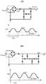
그리고 도 1의 (a),(b),(c)는 복수의 LED를 갖는 병렬 접속 구조의 교류 다이렉트 방식 LED 구동회로들을 보인 것이다.1 (a), 1 (b), and 1 (c) illustrate AC direct type LED driving circuits of a parallel connection structure having a plurality of LEDs.
도시된 바와 같이, 각 LED 그룹의 LED 개수의 총합은 인가된 입력전압의 피크값으로 결정되며, 이러한 구조에서의 시간에 따른 LED 빛의 세기는 아래의 수식으로 계산될 수 있다.As shown, the sum of the number of LEDs in each LED group is determined by the peak value of the applied input voltage, and the intensity of the LED light over time in this structure can be calculated by the following equation.
도 2를 참조하면, 도 2는 기본 병렬 접속 구조의 교류 다이렉트 방식 LED 구동회로에서의 전류 형태를 보인 것으로서,2, FIG. 2 shows a current type in an AC direct LED driving circuit of a basic parallel connection structure,
- 전체 LED turn-off 구간 : 0- Total LED turn-off interval: 0
- a 구간 :(LED1)의 LED 개수 × ILED1- Section a: Number of LEDs of (LED1) × ILED1
- b 구간 : (LED1+LED2)의 LED 개수 × ILED2- Section b: Number of LEDs of (LED1 + LED2) × ILED2
- c 구간 : (LED1+LED2+LED3)의 LED 개수 × ILED3- c section: Number of LEDs of (LED1 + LED2 + LED3) × ILED3
- d 구간 : (LED1+LED2+LED3+LED4)의 LED 개수 × ILED4- d section: Number of LEDs of (LED1 + LED2 + LED3 + LED4) × ILED4
(계산의 편의상 LED는 동일 특성을 가지며, LED의 빛은 전류와 선형적인 관계에 있고, 채널은 4개로써 병렬 접속된 것으로 가정한 것임)(For the sake of simplicity, the LEDs have the same characteristics, the LED light is linearly related to the current, and the four channels are assumed to be connected in parallel)
위 수식의 결과에서 알 수 있는 바와 같이, 한 사이클에서의 LED 빛의 세기의 편차는 0에서 (LED1+LED2+LED3+LED4)의 LED 개수 × ILED4로 큰 차이값을 가지게 된다.As can be seen from the above expression, the deviation of the intensity of the LED light in one cycle has a large difference value from 0 to (LED1 + LED2 + LED3 + LED4) × number of LEDs ILED4.
본 발명은 상기와 같은 문제점을 해결하기 위해 제안된 것으로서, 교류 다이렉트형 LED 구동회로 및 이를 이용한 LED 조명기기에서 각 LED 그룹이 켜질 때의 각 시간에 따른 빛 세기의 최소, 최대값 간 차이를 줄여 빛의 흔들림 정도(플리커 현상)를 감소시키는 플리커 저감 기능을 갖는 교류 다이렉트 방식의 LED 구동회로를 제공하는데 목적이 있다.SUMMARY OF THE INVENTION The present invention has been proposed in order to solve the above problems, and it is an object of the present invention to reduce the difference between the minimum and maximum values of light intensity according to each time when each LED group is turned on in the AC direct LED driving circuit, And an object of the present invention is to provide an LED driving circuit of an AC direct type having a flicker reduction function for reducing the degree of flickering of light (flicker phenomenon).
또한 본 발명은 교류 다이렉트형 LED 구동회로의 기본회로에 독립적인 온/오프 동작 및 전류 크기의 제어 기능이 있는 전류채널을 추가하여 해당 교류 다이렉트 방식 LED 구동회로의 모든 채널에서 이전 채널 스위칭 회로부의 온/오프 동작 및 전류에 구애받지 않고 LED 빛 세기의 최소값 및 최대값 간의 차이 값을 보다 능동적으로 줄일 수 있고, 추가되는 전류채널은 교류 다이렉트형 LED 구동회로의 기본회로를 통한 전류채널과 상관없이 온/오프 제어될 수 있으면서 전류 크기의 변경도 자유로운 플리커 저감 기능을 갖는 교류 다이렉트 방식의 LED 구동회로를 제공하는데 목적이 있다.Further, the present invention is characterized in that a current channel having an independent ON / OFF operation and a current size control function is added to the basic circuit of the AC direct type LED driving circuit, so that all the channels of the AC direct type LED driving circuit The difference value between the minimum value and the maximum value of the LED light intensity can be actively reduced regardless of the off operation and the current, and the added current channel can be set to a constant value regardless of the current channel through the basic circuit of the AC direct LED driving circuit And to provide an LED driving circuit of an AC direct type having a flicker reduction function which can be controlled to be off-controlled and freely changeable in current size.
상기와 같은 목적을 달성하기 위해 본 발명에 따른 플리커 저감 기능을 갖는 교류 다이렉트 방식의 LED 구동회로는, 전원공급부와의 접속점으로부터 최단 거리에 위치한 제1 LED를 시작으로 상기 전원공급부에서 최장 거리에 위치한 제n LED를 포함하는 LED 조명부와, 상기 LED 조명부를 형성하는 LED의 출력단에 접속되어 LED에 대한 전류공급채널을 형성하는 복수의 스위칭 회로부와, 상기 LED 조명부를 형성하는 LED의 출력단에 개별 접속되는 스위치 및 상기 스위치들을 연결하는 보조전원 공급라인을 포함하는 보조 채널부와, 상기 전원공급부를 포함하는 상태로 그 출력단이 상기 LED 조명부의 제1 LED와 접속되어 상기 스위칭 회로부 및 보조 채널부에 전원을 공급하는 밸리-필 (Valley-Fill) 회로부를 포함하여 구성된다.In order to achieve the above object, the present invention provides an LED driving circuit of an AC direct type having a flicker reduction function, the LED driving circuit comprising: a first LED positioned at a shortest distance from a connection point to a power supply unit; A plurality of switching circuit units connected to the output terminals of the LEDs forming the LED lighting units to form current supply channels for the LEDs, and a plurality of switching circuits connected to the output terminals of the LEDs forming the LED lighting units An auxiliary channel unit including a switch and an auxiliary power supply line for connecting the switches and an output terminal connected to the first LED of the LED lighting unit in a state including the power supply unit to supply power to the switching circuit unit and the auxiliary channel unit And a Valley-Fill circuit portion to supply the voltage.
또한 상기 LED 조명부는 다수의 LED가 개별적인 LED 조명을 형성하는 형태, 둘 이상의 LED가 그룹을 이루어 형성되는 LED 조명이 하나 또는 둘 이상 연결되는 형태, 하나의 LED로 형성되는 LED 조명 및 둘 이상의 LED로 형성되는 LED 조명이 연결되는 형태 중 어느 하나의 형태로 형성되는 것을 특징으로 한다.In addition, the LED illumination unit may include a configuration in which a plurality of LEDs form an individual LED illumination, a configuration in which one or more LED lights formed by grouping two or more LEDs are connected, an LED illumination unit formed by one LED, And the LED lighting device is connected to the LED lighting device.
또한 상기 LED 조명부의 LED 조명이 제1 LED 조명부터 제n LED 조명부까지인 것으로 정할 때, 상기 제1 LED 조명 내지 제n LED 조명에 흐르는 전류의 크기가 ILED1〉ILED2〉ILED3〉… ILEDn 또는 (ILED1+ILED_AUX)〉ILED2〉ILED3〉… ILEDn의 조건 내에서 정해지는 것을 특징으로 한다.Also, when it is determined that the LED illumination of the LED illumination unit is from the first LED illumination to the nth LED illumination unit, the magnitude of the current flowing in the first LED illumination through the nth LED illumination is ILED1> ILED2> ILED3> ILEDn or (ILED1 + ILED_AUX)> ILED2> ILED3> ... Lt; RTI ID = 0.0 > ILEDn. ≪ / RTI >
또한 상기 LED 조명부의 LED 조명이 제1 LED 조명부부터 제n LED 조명부까지인 것으로 정할 때, 상기 스위칭 회로부는 각각의 LED 조명별로 해당 LED 조명의 최종 LED의 출력단에 접속되고, 상기 보조 채널부의 스위치는 각각의 LED 조명별로 모든 LED의 출력단에 개별 접속되는 것을 특징으로 한다.In addition, when it is determined that the LED illumination of the LED illumination unit is from the first LED illumination unit to the nth LED illumination unit, the switching circuit unit is connected to the output end of the final LED of the corresponding LED illumination for each LED illumination, And are individually connected to the output terminals of all the LEDs according to the respective LED lights.
또한 상기 전원공급부는 교류전원 및 상기 교류전원의 정류회로를 포함하는 것을 특징으로 한다.The power supply unit may include an AC power supply and a rectifier circuit of the AC power supply.
본 발명에 따르면, 교류 다이렉트형 LED 구동회로 및 이를 이용한 LED 조명기기에서 각 LED 그룹이 켜질 때의 각 시간에 따른 빛 세기의 최소, 최대값 간 차이를 줄여 빛의 흔들림 정도(플리커 현상)를 감소시킬 수 있다.According to the present invention, in the AC direct LED driving circuit and the LED lighting device using the same, the difference between the minimum and maximum values of the light intensity according to each time when each LED group is turned on is reduced to reduce the flicker .
또한 교류 다이렉트형 LED 구동회로의 기본회로에 독립적인 온/오프 동작 및 전류 크기의 제어 기능이 있는 전류채널을 추가하여 이를 통해 해당 교류 다이렉트 방식 LED 구동회로의 모든 채널에서 이전 채널 스위칭 회로부의 온/오프 동작 및 전류에 구애받지 않고 LED 빛 세기의 최소값 및 최대값 간의 차이 값을 보다 능동적으로 줄일 수 있게 된다.In addition, a current channel having an independent on / off operation and a current size control function is added to the basic circuit of the AC direct type LED driving circuit, thereby enabling the on / off operation of the previous channel switching circuit in all channels of the corresponding AC direct type LED driving circuit, It is possible to more actively reduce the difference value between the minimum value and the maximum value of the LED light intensity regardless of the off operation and the current.
도 1의 (a),(b),(c)는 복수의 LED를 갖는 병렬 접속 구조의 교류 다이렉트 방식 LED 구동회로를 보인 도면
도 2는 기본 병렬 접속 구조의 교류 다이렉트 방식 LED 구동회로에서의 전류 형태를 보인 도면
도 3의 (a)(b)는 본 발명의 일 실시예에 따른 플리커 저감 기능을 갖는 교류 다이렉트 방식의 LED 구동회로에 적용되는 밸리-필(Valley-Fill) 회로의 예를 보인 도면
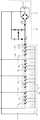
도 4는 도 3의 (a)가 적용된 본 발명의 일 실시예에 따른 플리커 저감 기능을 갖는 교류 다이렉트 방식의 LED 구동회로를 보인 도면
도 5는 도 4의 실시예에 따른 플리커 저감 기능을 갖는 교류 다이렉트 방식 LED 구동회로의 전류 파형을 보인 도면
도 6 및 도 7은 도 4의 실시예에 따른 플리커 저감 기능을 갖는 교류 다이렉트 방식 LED 구동회로의 도 5와 다른 형태로 적용된 전류 파형을 보인 도면
도 8 및 도 9는 도 4의 실시예에 따른 플리커 저감 기능을 갖는 교류 다이렉트 방식 LED 구동회로의 LED 조명들 간 전류 크기의 조건을 달리 했을 때 전류 파형을 보인 도면
도 10은 도 3의 (b)가 적용된 본 발명의 일 실시예에 따른 플리커 저감 기능을 갖는 교류 다이렉트 방식의 LED 구동회로를 보인 도면1 (a), 1 (b) and 1 (c) are views showing an AC direct type LED driving circuit of a parallel connection structure having a plurality of LEDs
2 is a diagram showing a current type in an AC direct LED driving circuit of a basic parallel connection structure
3 (a) and 3 (b) are views showing an example of a valley-fill circuit applied to an LED driving circuit of an AC direct type having a flicker reduction function according to an embodiment of the present invention
4 is a view showing an LED driving circuit of an AC direct type having a flicker reduction function according to an embodiment of the present invention to which FIG. 3 (a) is applied
5 is a view showing a current waveform of an AC direct type LED driving circuit having a flicker reduction function according to the embodiment of FIG.
6 and 7 are diagrams showing a current waveform applied in a different form to that of FIG. 5 of the AC direct type LED driver circuit having the flicker reduction function according to the embodiment of FIG.
8 and 9 are graphs showing current waveforms when the conditions of current magnitude between LED lights of an AC direct LED drive circuit having a flicker reduction function according to the embodiment of FIG.
10 is a view showing an LED driving circuit of an AC direct type having a flicker reduction function according to an embodiment of the present invention to which FIG. 3 (b) is applied
이하에서는 첨부된 도면을 참조하여 본 발명의 일 실시예에 따른 플리커 저감 기능을 갖는 교류 다이렉트 방식의 LED 구동회로를 상세하게 설명한다.Hereinafter, an LED driving circuit of an AC direct type having a flicker reduction function according to an embodiment of the present invention will be described in detail with reference to the accompanying drawings.
도 3의 (a)(b)는 본 발명의 일 실시예에 따른 플리커 저감 기능을 갖는 교류 다이렉트 방식의 LED 구동회로에 적용되는 밸리-필(Valley-Fill) 회로의 예를 보인 도면이다.3 (a) and 3 (b) are diagrams illustrating an example of a valley-fill circuit applied to an LED driving circuit of an ac direct type having a flicker reduction function according to an embodiment of the present invention.
그리고 도 4는 도 3의 (a)가 적용된 본 발명의 일 실시예에 따른 플리커 저감 기능을 갖는 교류 다이렉트 방식의 LED 구동회로를 보인 도면이다.4 is a diagram showing an LED driving circuit of an AC direct type having a flicker reduction function according to an embodiment of the present invention to which FIG. 3 (a) is applied.
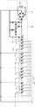
도시된 바와 같이, 본 발명의 일 실시예에 따른 플리커 저감 기능을 갖는 교류 다이렉트 방식의 LED 구동회로는 LED 조명부(100), 스위칭 회로부(200), 보조 채널부(300), 벨리-필(Valley-Fill) 회로부(400)를 포함하여 구성된다.As shown in the figure, an LED driving circuit of an AC direct type having a flicker reduction function according to an embodiment of the present invention includes an
LED 조명부(100)는 전원공급부(410)와의 접속점으로부터 최단 거리에 위치한 제1 LED(110a-1)를 시작으로 전원공급부(410)에서 최장 거리에 위치한 제n LED를 포함하여 구성된다. 그리고 LED 조명부(100)는 다수의 LED가 개별적인 LED 조명을 형성하는 형태, 둘 이상의 LED가 그룹을 이루어 형성되는 LED 조명이 하나 또는 둘 이상 연결되는 형태, 하나의 LED로 형성되는 LED 조명 및 둘 이상의 LED로 형성되는 LED 조명이 연결되는 형태 중 어느 하나의 형태로 형성되는 것일 수 있다.The
본 실시예에서는 이러한 LED 조명부(100)가 4개의 LED 조명(110~140)을 포함하며, 또한 각각의 LED 조명(110~140)이 4개의 LED(110a,120a,130a,140a)를 포함하는 형태인 것을 예로 하였다.In this embodiment, the
스위칭 회로부(200)는 LED 조명부(100)를 형성하는 LED의 출력단에 접속되어 LED에 대한 전류공급채널을 형성한다. 그리고 이러한 스위칭 회로부(200)는 LED 조명부(100)의 LED 조명(110~140)이 제1 LED 조명부터 제n LED 조명까지인 것으로 정할 때, 각 LED 조명별로 해당 LED 조명의 최종 LED의 출력단에 접속되는 것일 수 있다. 본 실시예를 기준으로 설명하면, 스위칭 회로부(200)는 제1 LED(110) 조명부터 제4 LED 조명(140)의 각 LED 조명(110~140)별 최종 LED의 출력단에 접속되는 네 개의 구성이다.The
보조 채널부(300)는 LED 조명부(100)를 형성하는 LED의 출력단에 개별 접속되는 스위치(310) 및 이러한 스위치(310)들을 연결하는 보조전원 공급라인(320)을 포함하여 구성된다. 그리고, 이러한 보조 채널부(300)는 LED 조명부(100)의 LED 조명(110~140)이 제1 LED 조명부터 제n LED 조명까지인 것으로 정할 때, 그 스위치(310)가 각각의 LED 조명(110~140)별로 모든 LED의 출력단에 개별 접속되는 것일 수 있다. 본 실시예를 기준으로 설명하면, 보조 채널부(300)의 스위치(310)는 제1 LED 조명(110) 내지 제4 LED 조명(140)에 포함된 모든 LED의 출력단에 개별 접속된다.The
밸리-필(Valley-Fill) 회로부(400)는 전원공급부(410)를 포함하는 상태로 그 출력단이 LED 조명부(100)의 제1 LED(110a-1)와 접속되어 스위칭 회로부(200) 및 보조 채널부(300)에 전원을 공급한다. 여기서, 전원공급부(410)는 교류전원 및 이러한 교류전원의 정류회로를 포함하는 것일 수 있다.The valley-
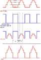
도 5를 참조하면, 도 5 는 도 4의 실시예에 따른 플리커 저감 기능을 갖는 교류 다이렉트 방식 LED 구동회로의 전류 파형을 보인 도면이다.Referring to FIG. 5, FIG. 5 is a diagram showing current waveforms of an AC direct LED driving circuit having a flicker reduction function according to the embodiment of FIG.
먼저, LED 주구동부의 전류 파형을 참조하여 각 구간별 빛의 세기를 계산하면 아래의 수식과 같다.First, referring to the current waveform of the LED main driving section, the light intensity of each section is calculated as shown below.
- a 구간 :(LED1)의 LED 개수 × ILED1- Section a: Number of LEDs of (LED1) × ILED1
- b 구간 : (LED1+LED2)의 LED 개수 × ILED2- Section b: Number of LEDs of (LED1 + LED2) × ILED2
- c 구간 : (LED1+LED2+LED3)의 LED 개수 × ILED3- c section: Number of LEDs of (LED1 + LED2 + LED3) × ILED3
- d 구간 : (LED1+LED2+LED3+LED4)의 LED 개수 × ILED4- d section: Number of LEDs of (LED1 + LED2 + LED3 + LED4) × ILED4
이러한 수식의 결과에서 알 수 있는 바와 같이, 한 사이클에서의 빛의 세기의 편차는 (LED1)의 LED개수×ILED1에서 (LED1+LED2+LED3+LED4)의 LED개수 × ILED4로써, 도 2를 참조하여 설명한 기본 병렬 접속 구조와 대비하여 LED 빛 세기의 최소값 및 최대값 간의 차이 값이 줄어듬을 확인할 수 있다.As can be seen from the results of this formula, the deviation of the intensity of light in one cycle is represented by the number of LEDs of LED1 × the number of LEDs of LED1 + LED2 + LED3 + LED4 × ILED4, The difference between the minimum value and the maximum value of the LED light intensity can be confirmed in comparison with the basic parallel connection structure described above.
또한 LED 보조구동부(보조채널부(300)+밸리-필 회로부(400))의 전류 파형을 통해 알 수 있는 바와 같이, LED 조명부(100) 및 스위칭 회로부(200)를 포함하는 교류 다이렉트 방식 LED 구동회로의 기본회로에 독립적으로 온/오프 동작 및 전류 크기의 제어 기능을 갖는 보조 채널부(300) 및 밸리-필 회로부(400)를 추가함으로써, 해당 교류 다이렉트 방식 LED 구동회로의 모든 채널에서 이전 채널 스위칭 회로부의 온/오프 동작 및 전류에 구애받지 않고 LED 빛 세기의 최소값 및 최대값 간의 차이 값을 보다 능동적으로 줄일 수 있다.As can be seen from the current waveforms of the LED auxiliary driving unit (
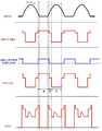
도 6 및 도 7은 도 4의 실시예에 따른 플리커 저감 기능을 갖는 교류 다이렉트 방식 LED 구동회로의 도 5와 다른 형태로 적용된 전류 파형을 보인 도면이다.FIGS. 6 and 7 are diagrams showing current waveforms applied to the AC direct type LED driving circuit having the flicker reduction function according to the embodiment of FIG. 4, in a mode different from that of FIG.
그리고 도 5 내지 도 7은 LED 조명부에 포함된 각 LED 조명의 전류 크기가 순차적으로 커지는 경우, 다시 말해 LED 조명부의 LED 조명이 제1 LED 조명부터 제n LED 조명까지인 것으로 정한 상태에서 ILED1〈ILED2〈ILED3〈… ILEDn인 경우를 예로 한 것이다.5 to 7 illustrate a case where the current magnitudes of LED lights included in the LED lighting unit sequentially increase, that is, when the LED lighting of the LED lighting unit is determined to be from the first LED lighting to the nth LED lighting, <ILED3 <... ILEDn as an example.
도 8 및 도 9는 이와 달리 LED 조명부에 포함된 각 LED 조명의 전류 크기가 ILED1〉ILED2〉ILED3〉… ILEDn 또는 (ILED1+ILED_AUX)〉ILED2〉ILED3〉… ILEDn인 경우 해당 교류 다이렉트 방식 LED 구동회로의 전류 파형을 보인 도면이다.FIGS. 8 and 9 are diagrams for explaining a case where the current magnitude of each LED illumination included in the LED illumination unit is ILED1> ILED2> ILED3> ILEDn or (ILED1 + ILED_AUX)> ILED2> ILED3> ... ILEDn, the current waveform of the AC direct type LED driving circuit is shown.
먼저, 도 8은 스위칭 회로부를 통한 ILED 채널을 4개로 구성한 경우 간략한 동작 파형을 보인 것이며, 도 9는 스위칭 회로부를 통한 ILED 채널을 3개로 구성한 경우 간략한 동작 파형을 보인 것이다.FIG. 8 shows a simple operation waveform when four ILED channels are provided through the switching circuit, and FIG. 9 shows a simple operation waveform when three ILED channels are provided through the switching circuit.
도 8의 각 구간별 빛의 세기를 계산하면 아래의 수식과 같다The light intensity of each section of FIG. 8 is calculated as shown in the following equation
- a 구간 :(LED1)의 LED 개수 × ILED1(또는 ILED1+ILED_AUX)- Section a: Number of LEDs of LED1 × ILED1 (or ILED1 + ILED_AUX)
- b 구간 : (LED1+LED2)의 LED 개수 × ILED2- Section b: Number of LEDs of (LED1 + LED2) × ILED2
- c 구간 : (LED1+LED2+LED3)의 LED 개수 × ILED3- c section: Number of LEDs of (LED1 + LED2 + LED3) × ILED3
- d 구간 : (LED1+LED2+LED3+LED4)의 LED 개수 × ILED4- d section: Number of LEDs of (LED1 + LED2 + LED3 + LED4) × ILED4
또한 도 9의 각 구간별 빛의 세기를 계산하면 아래의 수식과 같다In addition, the light intensity of each section of FIG. 9 is calculated as shown in the following equation
- a 구간 :(LED1)의 LED 개수 × ILED1(또는 ILED1+ILED_AUX)- Section a: Number of LEDs of LED1 × ILED1 (or ILED1 + ILED_AUX)
- b 구간 : (LED1+LED2)의 LED 개수 × ILED2- Section b: Number of LEDs of (LED1 + LED2) × ILED2
- c 구간 : (LED1+LED2+LED3)의 LED 개수 × ILED3- c section: Number of LEDs of (LED1 + LED2 + LED3) × ILED3
이러한 도 8 및 도 9를 참조한 수식을 통해 알 수 있는 바와 같이, 각 채널의 LED 개수가 증가할 때 반대로 각 채널에 흐르는 전류(ILED)값을 조정하여 각 구간(시간)별 빛의 세기를 동일하게 하면, 빛은 항상 동일한 값(DC)을 발생시킨다. 즉 Flicker-less의 구현이 가능해진다.8 and 9, when the number of LEDs of each channel increases, the value of the current ILED flowing through each channel is adjusted so that the light intensity of each section (time) is the same , The light always produces the same value (DC). In other words, it is possible to implement Flicker-less.
도 10은 도 3의 (b)가 적용된 본 발명의 일 실시예에 따른 플리커 저감 기능을 갖는 교류 다이렉트 방식의 LED 구동회로를 보인 도면이다.FIG. 10 is a diagram showing an LED driving circuit of an AC direct type having a flicker reduction function according to an embodiment of the present invention to which FIG. 3 (b) is applied.
그리고 이러한 도 10에 따른 플리커 저감 기능을 갖는 교류 다이렉트 방식 LED 구동회로의 전체적인 동작 및 작용은 도 4에 따른 플리커 저감 기능을 갖는 교류 다이렉트 방식 LED 구동회로 그것과 유사하므로 여기서 상세한 설명은 생략한다.The overall operation and operation of the AC direct type LED driver circuit having the flicker reduction function according to FIG. 10 is similar to that of the AC direct type LED driver circuit having the flicker reduction function according to FIG. 4, and thus a detailed description thereof will be omitted.
상술한 도 3 내지 도 10의 실시예들을 통하여 알 수 있는 바와 같이, 본 발명에 따른 플리커 저감 기능을 갖는 교류 다이렉트 방식의 LED 구동회로는, 교류 다이렉트형 LED 구동회로 및 이를 이용한 LED 조명기기에서 각 LED 그룹이 켜질 때의 각 시간에 따른 빛 세기의 최소, 최대값 간 차이를 줄여 빛의 흔들림 정도(플리커 현상)를 감소시킬 수 있게 한다.3 to 10, the LED driving circuit of the AC direct type having the flicker reduction function according to the present invention is characterized in that in the AC direct type LED driving circuit and the LED lighting device using the same, The difference between the minimum and maximum values of light intensity according to each time when the LED group is turned on can be reduced, thereby reducing the degree of flickering of the light (flicker phenomenon).
또한 교류 다이렉트형 LED 구동회로의 기본회로에 독립적인 온/오프 동작 및 전류 크기의 제어 기능이 있는 전류채널을 추가하여 이를 통해 해당 교류 다이렉트 방식 LED 구동회로의 모든 채널에서 이전 채널 스위칭 회로부의 온/오프 동작 및 전류에 구애받지 않고 LED 빛 세기의 최소값 및 최대값 간의 차이 값을 보다 능동적으로 줄일 수 있게 한다.In addition, a current channel having an independent on / off operation and a current size control function is added to the basic circuit of the AC direct type LED driving circuit, thereby enabling the on / off operation of the previous channel switching circuit in all channels of the corresponding AC direct type LED driving circuit, Thereby making it possible to more actively reduce the difference value between the minimum value and the maximum value of the LED light intensity regardless of the off operation and the current.
이상에서 설명한 것은 본 발명에 따른 플리커 저감 기능을 갖는 교류 다이렉트 방식의 LED 구동회로를 실시하기 위한 하나의 실시예에 불과한 것으로서, 본 발명은 상기한 실시 예에 한정되지 않고, 이하의 특허청구범위에서 청구하는 바와 같이 본 발명의 요지를 벗어남이 없이 당해 발명이 속하는 분야에서 통상의 지식을 가진 자라면 누구든지 다양한 변경 실시가 가능한 범위까지 본 발명의 기술적 정신이 있다고 할 것이다.
It is to be understood that the present invention is not limited to the above-described embodiment, but may be embodied in various forms without departing from the spirit or scope of the following claims. For example, It will be understood by those of ordinary skill in the art that various changes in form and details may be made therein without departing from the spirit and scope of the invention as defined in the appended claims.
100 : LED 조명부 110~140 : LED 조명
110a,120a,130a,140a : LED 200 : 스위칭 회로부
300 : 보조 채널부 310 : 스위치
320 : 보조전원 공급라인 400 : 밸리-필(Valley-Fill) 회로부
410 : 전원공급부100:
110a, 120a, 130a, 140a: LED 200: switching circuit
300: auxiliary channel unit 310: switch
320: Auxiliary power supply line 400: Valley-Fill circuit
410: Power supply
Claims (5)
Translated fromKorean상기 LED 조명부를 형성하는 LED의 출력단에 접속되어 LED에 대한 전류공급채널을 형성하는 복수의 스위칭 회로부;
상기 LED 조명부를 형성하는 LED의 출력단에 개별 접속되는 스위치 및 상기 스위치들을 연결하는 보조전원 공급라인을 포함하는 보조 채널부;
상기 전원공급부를 포함하는 상태로 그 출력단이 상기 LED 조명부의 제1 LED와 접속되어 상기 스위칭 회로부 및 보조 채널부에 전원을 공급하는 밸리-필 (Valley-Fill) 회로부를 포함하는 플리커 저감 기능을 갖는 교류 다이렉트 방식의 LED 구동회로.An LED illumination unit including an n-th LED located at a longest distance from the power supply unit, starting from a first LED located at a shortest distance from a connection point with the power supply unit;
A plurality of switching circuit units connected to output terminals of the LEDs forming the LED illumination unit to form current supply channels for the LEDs;
A supplementary channel unit including a switch individually connected to an output terminal of the LED forming the LED illumination unit and an auxiliary power supply line connecting the switches;
And a valley-fill circuit part having an output terminal connected to the first LED of the LED lighting part and supplying power to the switching circuit part and the auxiliary channel part in a state including the power supply part, AC direct LED drive circuit.
상기 LED 조명부는 다수의 LED가 개별적인 LED 조명을 형성하는 형태, 둘 이상의 LED가 그룹을 이루어 형성되는 LED 조명이 하나 또는 둘 이상 연결되는 형태, 하나의 LED로 형성되는 LED 조명 및 둘 이상의 LED로 형성되는 LED 조명이 연결되는 형태 중 어느 하나의 형태로 형성되는 것을 특징으로 하는 플리커 저감 기능을 갖는 교류 다이렉트 방식의 LED 구동회로.The method according to claim 1,
The LED illumination unit may be configured in such a manner that a plurality of LEDs form an individual LED illumination, a configuration in which one or more LED lights formed by grouping two or more LEDs are connected, an LED illumination formed by one LED, Wherein the LED driving circuit is formed in any one of a shape in which the LED lighting is connected to the LED driving circuit.
상기 LED 조명부의 LED 조명이 제1 LED 조명부터 제n LED 조명까지인 것으로 정할 때, 상기 제1 LED 조명 내지 제n LED 조명에 흐르는 전류의 크기가 ILED1〉ILED2〉ILED3〉… ILEDn 또는 (ILED1+ILED_AUX)〉ILED2〉ILED3〉… ILEDn의 조건 내에서 정해지는 것을 특징으로 하는 플리커 저감 기능을 갖는 교류 다이렉트 방식의 LED 구동회로.3. The method of claim 2,
When it is determined that the LED illumination of the LED illumination unit is from the first LED illumination to the nth LED illumination, the magnitude of the current flowing through the first LED illumination to the nth LED illumination is ILED1>ILED2>ILED3> ILEDn or (ILED1 + ILED_AUX)>ILED2>ILED3> ... The LED driving circuit having a flicker reduction function.
상기 LED 조명부의 LED 조명이 제1 LED 조명부터 제n LED 조명까지인 것으로 정할 때, 상기 스위칭 회로부는 각각의 LED 조명별로 해당 LED 조명의 최종 LED의 출력단에 접속되고, 상기 보조 채널부의 스위치는 각각의 LED 조명별로 모든 LED의 출력단에 개별 접속되는 것을 특징으로 하는 플리커 저감 기능을 갖는 교류 다이렉트 방식의 LED 구동회로.3. The method of claim 2,
When the LED illumination of the LED illumination unit is determined to be from the first LED illumination to the nth LED illumination, the switching circuit unit is connected to the output terminal of the final LED of the corresponding LED illumination for each LED illumination, Wherein the LED driving circuit is individually connected to the output terminals of all the LEDs according to the LED lighting of the direct-current LED driving circuit.
상기 전원공급부는 교류전원 및 상기 교류전원의 정류회로를 포함하는 것을 특징으로 하는 플리커 저감 기능을 갖는 교류 다이렉트 방식의 LED 구동회로.The method according to claim 1,
Wherein the power supply unit includes an AC power source and a rectifying circuit of the AC power source.
Priority Applications (1)
| Application Number | Priority Date | Filing Date | Title |
|---|---|---|---|
| KR20130083941AKR101464083B1 (en) | 2013-07-17 | 2013-07-17 | Ac direct connection type LED driving circuit having function of flicker reduction |
Applications Claiming Priority (1)
| Application Number | Priority Date | Filing Date | Title |
|---|---|---|---|
| KR20130083941AKR101464083B1 (en) | 2013-07-17 | 2013-07-17 | Ac direct connection type LED driving circuit having function of flicker reduction |
Publications (1)
| Publication Number | Publication Date |
|---|---|
| KR101464083B1true KR101464083B1 (en) | 2014-11-21 |
Family
ID=52291292
Family Applications (1)
| Application Number | Title | Priority Date | Filing Date |
|---|---|---|---|
| KR20130083941AActiveKR101464083B1 (en) | 2013-07-17 | 2013-07-17 | Ac direct connection type LED driving circuit having function of flicker reduction |
Country Status (1)
| Country | Link |
|---|---|
| KR (1) | KR101464083B1 (en) |
Cited By (2)
| Publication number | Priority date | Publication date | Assignee | Title |
|---|---|---|---|---|
| RU2634493C2 (en)* | 2016-03-17 | 2017-10-31 | Федеральное государственное бюджетное образовательное учреждение высшего профессионального образования "Томский государственный университет систем управления и радиоэлектроники" | Wiring diagram of led light device to ac system |
| CN109979132A (en)* | 2017-12-27 | 2019-07-05 | 航天信息股份有限公司 | A kind of list alarm lamp indicates the method and system of more equipment alarm states |
Citations (5)
| Publication number | Priority date | Publication date | Assignee | Title |
|---|---|---|---|---|
| JP2005173523A (en)* | 2003-12-08 | 2005-06-30 | Beyond Innovation Technology Co Ltd | Low visual noise PWM lighting control circuit for LED drive |
| KR20110005559A (en)* | 2009-07-10 | 2011-01-18 | 주식회사 현대엘이디 | Power supply for light emitting diode with flicker removal circuit |
| KR20110046254A (en)* | 2009-10-26 | 2011-05-04 | 샤프 가부시키가이샤 | LED driving circuits, LED lighting fixtures, LED lighting equipment, and LED lighting systems |
| KR20110074650A (en)* | 2009-12-25 | 2011-07-01 | 샤프 가부시키가이샤 | LED drive circuits, phase controlled dimmers, LED lighting fixtures, LED lighting devices, and LED lighting systems |
| KR20120043188A (en)* | 2010-10-26 | 2012-05-04 | (주)로그인디지탈 | Ac direct connection type led lighting device having function of flicker reduction and improving light efficiency |
- 2013
- 2013-07-17KRKR20130083941Apatent/KR101464083B1/enactiveActive
Patent Citations (5)
| Publication number | Priority date | Publication date | Assignee | Title |
|---|---|---|---|---|
| JP2005173523A (en)* | 2003-12-08 | 2005-06-30 | Beyond Innovation Technology Co Ltd | Low visual noise PWM lighting control circuit for LED drive |
| KR20110005559A (en)* | 2009-07-10 | 2011-01-18 | 주식회사 현대엘이디 | Power supply for light emitting diode with flicker removal circuit |
| KR20110046254A (en)* | 2009-10-26 | 2011-05-04 | 샤프 가부시키가이샤 | LED driving circuits, LED lighting fixtures, LED lighting equipment, and LED lighting systems |
| KR20110074650A (en)* | 2009-12-25 | 2011-07-01 | 샤프 가부시키가이샤 | LED drive circuits, phase controlled dimmers, LED lighting fixtures, LED lighting devices, and LED lighting systems |
| KR20120043188A (en)* | 2010-10-26 | 2012-05-04 | (주)로그인디지탈 | Ac direct connection type led lighting device having function of flicker reduction and improving light efficiency |
Cited By (2)
| Publication number | Priority date | Publication date | Assignee | Title |
|---|---|---|---|---|
| RU2634493C2 (en)* | 2016-03-17 | 2017-10-31 | Федеральное государственное бюджетное образовательное учреждение высшего профессионального образования "Томский государственный университет систем управления и радиоэлектроники" | Wiring diagram of led light device to ac system |
| CN109979132A (en)* | 2017-12-27 | 2019-07-05 | 航天信息股份有限公司 | A kind of list alarm lamp indicates the method and system of more equipment alarm states |
Similar Documents
| Publication | Publication Date | Title |
|---|---|---|
| US9560704B2 (en) | LED driving device and LED lighting apparatus | |
| JP6471883B2 (en) | Lighting device | |
| TWI404452B (en) | Current supply circuit and current control circuit for led | |
| TWI432087B (en) | An arrangement for driving led cells | |
| CN105025632B (en) | A kind of LED lamp and its control circuit of switch toning | |
| TWI584672B (en) | Multicolor led driver structure | |
| CN103152932A (en) | LED (Light Emitting Diode) drive circuit capable of adjusting light and color temperature | |
| JP2017054653A (en) | Lighting device, illumination device and luminaire | |
| JP2012142132A (en) | Led lighting device and lighting equipment using it | |
| JP6174647B2 (en) | Low flicker LED lighting equipment | |
| KR101464083B1 (en) | Ac direct connection type LED driving circuit having function of flicker reduction | |
| KR101028460B1 (en) | Power Supply for Power LED Drive Using Microcontroller | |
| JP2017112111A (en) | Lighting apparatus and system having electrical insulation structure between dimmer and driver | |
| CN103152934A (en) | LED (Light Emitting Diode) drive circuit capable of adjusting light and color temperature | |
| CN103179750A (en) | Adjustable-color-temperature dimmable LED (light emitting diode) driving circuit | |
| KR102165446B1 (en) | Apparatus for driving light emitting diode | |
| KR20140059627A (en) | Controlling apparatus and method for driving and dimming of light emitting diode | |
| KR101132408B1 (en) | Led operating device | |
| JP2016015238A (en) | Three-color led lighting control lamp | |
| CN203104906U (en) | LED (light emitting diode) driving circuit capable of adjusting light and color temperature | |
| JP5750592B2 (en) | LIGHTING DEVICE AND LIGHTING APPARATUS USING THE LIGHTING DEVICE | |
| KR101598131B1 (en) | Apparatus for Cross Drive Control of LED lighting | |
| JP5815387B2 (en) | LED lighting device and method for controlling LED lighting device | |
| US9699843B2 (en) | Power supply device for LED light | |
| JP2016122617A (en) | Lighting device, illumination equipment using the lighting device and illumination system using the illumination equipment |
Legal Events
| Date | Code | Title | Description |
|---|---|---|---|
| PA0109 | Patent application | Patent event code:PA01091R01D Comment text:Patent Application Patent event date:20130717 | |
| PA0201 | Request for examination | ||
| E701 | Decision to grant or registration of patent right | ||
| PE0701 | Decision of registration | Patent event code:PE07011S01D Comment text:Decision to Grant Registration Patent event date:20141113 | |
| GRNT | Written decision to grant | ||
| PR0701 | Registration of establishment | Comment text:Registration of Establishment Patent event date:20141114 Patent event code:PR07011E01D | |
| PR1002 | Payment of registration fee | Payment date:20141114 End annual number:3 Start annual number:1 | |
| PG1601 | Publication of registration | ||
| FPAY | Annual fee payment | Payment date:20171103 Year of fee payment:4 | |
| PR1001 | Payment of annual fee | Payment date:20171103 Start annual number:4 End annual number:4 | |
| FPAY | Annual fee payment | Payment date:20181105 Year of fee payment:5 | |
| PR1001 | Payment of annual fee | Payment date:20181105 Start annual number:5 End annual number:5 | |
| FPAY | Annual fee payment | Payment date:20191106 Year of fee payment:6 | |
| PR1001 | Payment of annual fee | Payment date:20191106 Start annual number:6 End annual number:6 | |
| PR1001 | Payment of annual fee | Payment date:20201110 Start annual number:7 End annual number:7 | |
| PR1001 | Payment of annual fee | Payment date:20221025 Start annual number:9 End annual number:9 |