KR101462100B1 - Positioning device for seabed and underwater positioning system using the same - Google Patents
Positioning device for seabed and underwater positioning system using the sameDownload PDFInfo
- Publication number
- KR101462100B1 KR101462100B1KR1020140082891AKR20140082891AKR101462100B1KR 101462100 B1KR101462100 B1KR 101462100B1KR 1020140082891 AKR1020140082891 AKR 1020140082891AKR 20140082891 AKR20140082891 AKR 20140082891AKR 101462100 B1KR101462100 B1KR 101462100B1
- Authority
- KR
- South Korea
- Prior art keywords
- laser output
- submarine
- signal
- laser
- control unit
- Prior art date
- Legal status (The legal status is an assumption and is not a legal conclusion. Google has not performed a legal analysis and makes no representation as to the accuracy of the status listed.)
- Expired - Fee Related
Links
Images


Classifications
- G—PHYSICS
- G01—MEASURING; TESTING
- G01S—RADIO DIRECTION-FINDING; RADIO NAVIGATION; DETERMINING DISTANCE OR VELOCITY BY USE OF RADIO WAVES; LOCATING OR PRESENCE-DETECTING BY USE OF THE REFLECTION OR RERADIATION OF RADIO WAVES; ANALOGOUS ARRANGEMENTS USING OTHER WAVES
- G01S1/00—Beacons or beacon systems transmitting signals having a characteristic or characteristics capable of being detected by non-directional receivers and defining directions, positions, or position lines fixed relatively to the beacon transmitters; Receivers co-operating therewith
- G01S1/72—Beacons or beacon systems transmitting signals having a characteristic or characteristics capable of being detected by non-directional receivers and defining directions, positions, or position lines fixed relatively to the beacon transmitters; Receivers co-operating therewith using ultrasonic, sonic or infrasonic waves
- G—PHYSICS
- G01—MEASURING; TESTING
- G01S—RADIO DIRECTION-FINDING; RADIO NAVIGATION; DETERMINING DISTANCE OR VELOCITY BY USE OF RADIO WAVES; LOCATING OR PRESENCE-DETECTING BY USE OF THE REFLECTION OR RERADIATION OF RADIO WAVES; ANALOGOUS ARRANGEMENTS USING OTHER WAVES
- G01S11/00—Systems for determining distance or velocity not using reflection or reradiation
- G01S11/14—Systems for determining distance or velocity not using reflection or reradiation using ultrasonic, sonic, or infrasonic waves
- G—PHYSICS
- G01—MEASURING; TESTING
- G01S—RADIO DIRECTION-FINDING; RADIO NAVIGATION; DETERMINING DISTANCE OR VELOCITY BY USE OF RADIO WAVES; LOCATING OR PRESENCE-DETECTING BY USE OF THE REFLECTION OR RERADIATION OF RADIO WAVES; ANALOGOUS ARRANGEMENTS USING OTHER WAVES
- G01S3/00—Direction-finders for determining the direction from which infrasonic, sonic, ultrasonic, or electromagnetic waves, or particle emission, not having a directional significance, are being received
- G01S3/80—Direction-finders for determining the direction from which infrasonic, sonic, ultrasonic, or electromagnetic waves, or particle emission, not having a directional significance, are being received using ultrasonic, sonic or infrasonic waves
- G01S3/801—Details
Landscapes
- Engineering & Computer Science (AREA)
- Physics & Mathematics (AREA)
- General Physics & Mathematics (AREA)
- Radar, Positioning & Navigation (AREA)
- Remote Sensing (AREA)
- Computer Networks & Wireless Communication (AREA)
- Measurement Of Velocity Or Position Using Acoustic Or Ultrasonic Waves (AREA)
Abstract
Translated fromKoreanDescription
Translated fromKorean이 발명은 해저용 위치확인장치 및 이를 이용한 수중 위치확인시스템에 관한 것으로서, 보다 상세하게는 해저에서 운용중인 계측장치나 해저구조물, 그리고 수중에서 작업중인 다이버의 위치를 시각적으로 용이하게 파악할 수 있도록 한 것이다.The present invention relates to a submarine positioning apparatus and a submarine position confirmation system using the submarine positioning apparatus, and more particularly, to a submarine positioning apparatus and a submarine positioning apparatus that can visually and easily grasp a position of a diver will be.
특히, 이 발명은 해저용 위치확인장치의 설치 및 회수가 매우 용이할 뿐만 아니라, 저가의 해저용 위치확인장치로도 충분한 위치확인이 가능하도록 함으로써, 다양한 분야에서 널리 활용 및 운용할 수 있도록 한 해저용 위치확인장치 및 이를 이용한 수중 위치확인시스템에 관한 것이다.
Particularly, the present invention is very easy to install and recover the seabed position determining device, and enables a sufficient position confirmation even with a low-cost submarine positioning device, thereby making it possible to widely use and operate the seabed And an underwater position confirmation system using the same.
해양자원의 이용 및 개발로 인해 해양에 대한 중요성은 날로 증가하고 있으며, 다양한 계측장치나 구조물 등을 이용하여 해양에서 일어나는 여러 가지 현상을 과학적으로 연구하고 있다.Due to the use and development of marine resources, the importance of the ocean is increasing day by day, and various phenomena occurring in the ocean are scientifically studied using various measurement devices and structures.
해양에서의 과학적 연구에 있어서, 측정된 계측데이터가 정보로서의 가치를 가지기 위해서는 해당 계측데이터의 측정위치를 정확히 파악하는 것이 중요하나, 육상에서와 달리 해양에서는 그 환경적 특성으로 인해 계측장치나 구조물들의 위치를 정확하게 확인하는 것에 어려움이 있다.In scientific research in the ocean, it is important to accurately grasp the measurement location of the measurement data in order for the measured data to have value as information. However, unlike onshore, due to its environmental characteristics, There is a difficulty in accurately checking the position.
특히, 육상에서 사용하는 무선통신방식을 수중에서 이용하게 되면 신호의 감쇄가 매우 크게 발생하게 되어, 일반적으로 알려진 위치확인기술을 수중에서 이용하기에는 어려움이 많았다.In particular, if the wireless communication system used in the land is used in water, the attenuation of the signal becomes very large, and it is difficult to use a generally known positioning technique in water.
이에, 수중에서는 주로 음파신호를 이용하여 특정 위치를 확인 및 추적하게 되며, 주로 복수개의 트랜스폰더를 이용하여 삼각측량으로 추적대상에 구성된 트랜시버의 위치를 측정하는 방법이 사용되고 있다.Accordingly, a specific position is mainly identified and tracked by using an acoustic wave signal in the water, and a method of measuring the position of a transceiver configured to be traced by triangulation using mainly a plurality of transponders is used.
하기의 선행기술문헌인 대한민국 등록특허공보 제10-1180331호 '수중로봇의 위치 측정장치'(이하, '선행기술'이라 함)는, 수중에서 작업하는 수중로봇의 위치를 삼각측량으로 확인하는 기술에 관한 것이다.The following prior art document, Korean Patent Registration No. 10-1180331 entitled " Prior Art " (hereafter referred to as " Prior Art ") describes a technique for confirming the position of an underwater robot working underwater by triangulation .
선행기술을 포함하는 종래의 수중위치추적 기술은 모두 트랜스폰더와 트랜시버의 자세와 위치를 정확하게 측정하기 위한 캘리브레이션 과정을 필요로 하는 바, 긴급한 상황에서 다이버나 잠수정을 이용해 수중 작업을 수행해야 하는 경우 각 장치들의 설치작업 및 캘리브레이션 과정은 상당한 시간 부담을 초래하는 문제점이 있었다.Conventional underwater location tracking techniques, including prior art, require a calibration process to accurately measure the posture and position of the transponder and transceiver, and in the event that an underwater operation is to be performed using a diver or a submersible in an emergency, There has been a problem that the installation work and the calibration process of the devices cause considerable time burden.
더욱이, 종래의 수중위치추적을 위한 장치들은 대부분 고가이기 때문에, 운용상에 제약이 발생하여 특정분야에서만 활용될 뿐이며, 활용되는 경우에도 그 횟수가 매우 제한적일 수 밖에 없었다.
In addition, since the conventional devices for tracking the underwater position are mostly expensive, there is a limitation in operation, and the devices are used only in a specific field, and the number of times of use is very limited.
상기와 같은 문제점을 해결하기 위해서, 이 발명은 저가의 해저용 위치확인장치로도 충분한 위치확인이 가능하도록 함으로써, 다양한 분야에서 널리 활용 및 운용할 수 있도록 한 해저용 위치확인장치 및 이를 이용한 수중 위치확인시스템을 제공하는데 목적이 있다.In order to solve the above problems, the present invention has been made to solve the above-mentioned problems, and it is an object of the present invention to provide a submarine positioning device capable of sufficiently positioning even a low- It is aimed to provide a verification system.
특히, 캘리브레이션 등의 복잡한 과정을 수행하지 않고서도, 해저에서 운용중인 계측장치(해저용 측정장치)나 해저구조물, 그리고 수중에서 작업중인 다이버의 위치를 시각적으로 용이하게 파악할 수 있도록 한 해저용 위치확인장치 및 이를 이용한 수중 위치확인시스템을 제공하는데 목적이 있다.Particularly, it is possible to provide a positioning device for a submarine (a submarine measuring device) and a submarine structure that are operated by the sea floor without performing a complicated process such as calibration, and a submarine positioning And an object thereof is to provide an apparatus and an underwater position confirmation system using the same.
또한, 이 발명은 해저용 위치확인장치의 설치 및 회수가 매우 용이할 뿐만 아니라, 다이버가 휴대용 음파송신기를 이용하여 위급상황시 자신의 위치를 신속하게 알려줌으로써, 해양에서 발생되는 사고에 대하여 신속한 대처가 가능하도록 한 해저용 위치확인장치 및 이를 이용한 수중 위치확인시스템을 제공하는데 목적이 있다.
In addition, the present invention is very easy to install and recover the seabed position determining device, and also allows the diver to quickly inform the user of his / her position in an emergency using a portable sound wave transmitter, And to provide an underwater position confirmation system using the same.
상기와 같은 목적을 달성하기 위해서, 이 발명에 따른 해저용 위치확인장치는, 해수면을 향하여 상부방향으로 레이저를 출력하는 레이저출력부와, 일정한 패턴에 따라 레이저가 출력되도록 상기 레이저출력부의 동작을 제어하는 출력제어부와, 동작시간, 단위동작시간 및 출력신호패턴 중 적어도 하나를 포함하는 출력설정정보가 저장된 설정정보저장부를 포함하는 레이저출력모듈; 및 해저면에 설치되고 상부에 상기 레이저출력모듈이 구성되는 베이스구조체;를 포함하고, 상기 출력제어부는, 상기 설정정보저장부에 저장된 출력설정정보에 대응하여 상기 레이저출력부의 동작을 제어한다.In order to achieve the above object, the seafloor position determining apparatus according to the present invention comprises: a laser output unit for outputting a laser in an upward direction toward the sea surface; and a control unit for controlling the operation of the laser output unit And a setting information storage unit in which output setting information including at least one of an operation time, a unit operation time, and an output signal pattern is stored; And a base structure installed on the undersurface and having the laser output module formed thereon. The output control unit controls the operation of the laser output unit according to the output setting information stored in the setting information storage unit.
삭제delete
또한, 상기 레이저출력모듈은, 외부에서 전송된 음파신호를 수신하는 음파수신부;를 더 포함하고, 상기 출력제어부는, 수신된 음파신호를 분석하고, 분석결과에 따른 출력설정정보를 호출하여 상기 레이저출력부의 동작을 제어할 수 있다.The laser output module may further include a sound wave receiver for receiving an externally transmitted sound wave signal, wherein the output controller analyzes the received sound wave signal, and calls output setting information according to the analysis result, The operation of the output unit can be controlled.
또한, 상기 베이스구조체의 하부에는, 상기 베이스구조체를 자유낙하방식으로 하강시키는 중량체가 구성될 수 있다.In addition, a weight for lowering the base structure by a free fall method may be formed at a lower portion of the base structure.
또한, 상기 레이저출력모듈은, 상부방향을 기준으로 상기 레이저출력모듈의 흔들림을 측정하는 자이로스코프센서; 상기 자이로스코프센서의 측정데이터에 기초하여 상기 레이저출력부의 레이저 출력방향이 상부방향을 유지하도록 자세보정제어신호를 생성하는 자세제어부; 및 상기 자세제어부에서 생성된 자세보정제어신호에 대응하여 상기 레이저출력모듈을 롤링(Rolling) 및 피칭(Pitching) 중 적어도 하나로 회동시키는 RP구동부;를 더 포함할 수 있다.The laser output module may include: a gyroscope sensor for measuring a shake of the laser output module with respect to an upper direction; An attitude control unit for generating an attitude correction control signal so that a laser output direction of the laser output unit maintains an upward direction based on measurement data of the gyroscope sensor; And an RP driving unit for rotating the laser output module in at least one of rolling and pitching in accordance with the attitude correction control signal generated by the attitude control unit.
또한, 상기 레이저출력모듈은, 상부방향을 기준으로 상기 레이저출력모듈의 흔들림을 측정하는 자이로스코프센서; 및 상기 자이로스코프센서의 측정데이터에 기초하여 상기 레이저출력부의 레이저 출력방향이 상부방향을 유지하도록 자세보정제어신호를 생성하는 자세제어부;를 더 포함하고, 상기 베이스구조체는, 상기 자세제어부에서 생성된 자세보정제어신호에 대응하여 상기 레이저출력모듈을 롤링(Rolling)시키는 롤링밸러스트탱크; 및 상기 자세제어부에서 생성된 자세보정제어신호에 대응하여 상기 레이저출력모듈을 피칭(Pitching)시키는 피칭밸러스트탱크;를 더 포함할 수 있다.The laser output module may include: a gyroscope sensor for measuring a shake of the laser output module with respect to an upper direction; And an attitude control unit for generating an attitude correction control signal so that a laser output direction of the laser output unit maintains an upward direction based on measurement data of the gyroscope sensor, A rolling ballast tank for rolling the laser output module in response to an attitude correction control signal; And a pitching ballast tank for pitching the laser output module corresponding to the attitude correction control signal generated by the attitude control unit.
또한, 상기 자세제어부는, 상기 롤링밸러스트탱크 및 피칭밸러스트탱크를 동시에 제어하여 상기 레이저출력모듈을 상승 또는 하강시킬 수 있다.The posture controller may control the rolling ballast tank and the pitching ballast tank simultaneously to raise or lower the laser output module.
또한, 이 발명에 따른 해저용 위치확인장치를 이용한 수중 위치확인시스템은, 위치확인신호를 음파신호로 송출하는 휴대용 음파송신기; 해저면에 설치되고 상기 휴대용 음파송신기로부터 송출된 음파신호를 수신하여 위치확인신호를 확인하고, 상기 위치확인신호에 대응하여 해수면을 향하여 상부방향으로 레이저를 출력하는 해저용 위치확인장치; 및 상기 해저용 위치확인장치와 통신을 수행하는 원격감시서버;를 포함하고, 상기 위치확인신호는, 정상상태 위치확인신호, 위험상태 위치확인신호 및 응급상태 위치확인신호 중 적어도 하나를 포함하고, 상기 해저용 위치확인장치는, 수신된 위치확인신호를 분석하여, 각 상태별로 설정된 패턴에 대응하여 상부방향으로 레이저를 출력하고, 위험상태 위치확인신호 및 응급상태 위치확인신호 중 적어도 하나가 확인되면, 상기 원격감시서버에 해당 상황을 통보하며, 상기 원격감시서버는, 상기 해저용 위치확인장치가 설치된 수역에서 위험상황 및 응급상황이 발생됨을 통보받으면, 해당 수역에 위치하는 선박 및 대응기관서버에 해당 상황에 따른 대응을 요청할 수 있다.According to another aspect of the present invention, there is provided an underwater position determination system using a submarine position determining apparatus, comprising: a portable sound wave transmitter for transmitting a position confirmation signal as an acoustic wave signal; A submarine positioning device installed on the sea floor for receiving a sound wave signal transmitted from the portable sound wave transmitter to confirm the position confirmation signal and outputting the laser in the upward direction toward the sea surface in response to the position confirmation signal; And a remote monitoring server for communicating with the submarine positioning device, wherein the positioning signal comprises at least one of a steady state position signal, a critical state position signal and an emergency position signal, The submarine positioning apparatus analyzes the received positioning signal, outputs a laser in an upward direction corresponding to a pattern set for each state, and when at least one of the critical state position confirmation signal and the emergency state position confirmation signal is confirmed The remote monitoring server notifies the remote monitoring server of the situation and when the remote monitoring server is notified of the occurrence of a dangerous situation and an emergency situation in the water area where the submarine positioning apparatus is installed, And may request a response according to the situation.
또한, 상기 해저용 위치확인장치는 복수개가 해저면에 일정간격으로 설치되어, ad-hoc 통신방식의 센서네트워크 기반으로 통신을 수행하며, 복수개의 해저용 위치확인장치 중 상기 위치확인신호를 수신한 해저용 위치확인장치들은, 상기 위치확인신호의 수신시간정보를 서로 교환하여 비교하고, 상기 위치확인신호의 수신시간이 가장 빠른 해저용 위치확인장치가 설정된 패턴에 대응하여 레이저를 출력할 수 있다.In addition, a plurality of submarine positioning apparatuses are installed at regular intervals on the sea floor to perform communication on the basis of a sensor network of an ad-hoc communication system, and receive the positioning signal among a plurality of submarine positioning apparatuses The submarine positioning apparatuses can exchange the reception time information of the position confirmation signals with each other and compare the same with each other and output the laser corresponding to the pattern set by the submarine positioning apparatus having the fastest receiving time of the position confirmation signal.
삭제delete
또한, 상기 해저용 위치확인장치로부터 수중 음파통신으로 상기 위치확인신호를 수신하고, 수신된 위치확인신호를 육상 무선통신용 데이터로 변환하여 상기 원격감시서버에 전송하는 중계장치를 더 포함할 수 있다.
The mobile communication terminal may further include a relay device for receiving the location confirmation signal from the submarine positioning device through underwater acoustic communication, converting the received location confirmation signal into data for terrestrial radio communication, and transmitting the data to the remote monitoring server.
상기와 같은 해결수단에 의해, 이 발명은 저가의 해저용 위치확인장치로도 충분한 위치확인이 가능하도록 함으로써, 다양한 분야에서 널리 활용 및 운용할 수 있는 장점이 있다.According to the above-described solution, the present invention is advantageous in that it can be widely utilized and operated in various fields by making it possible to confirm a sufficient position even with a low-cost submarine positioning device.
또한, 이 발명은 캘리브레이션 등의 복잡한 연산처리과정을 필요로 하지 않기 때문에, 신속한 위치확인이 가능하다는 장점이 있다.Further, the present invention does not require a complicated arithmetic processing process such as calibration, and thus has an advantage that it is possible to quickly confirm the position.
특히, 이 발명은 해저에서 운용중인 계측장치(해저용 측정장치)나 해저구조물, 그리고 수중에서 작업중인 다이버의 위치를 시각적으로 확인할 수 있도록 함으로써, 수중에서의 위치를 용이하게 파악할 수 있는 효과가 있다.In particular, the present invention has an effect that the position in the water can be easily grasped by making it possible to visually check the position of a measuring device (submarine measuring device), a submarine structure, .
또한, 이 발명은 해저용 위치확인장치의 설치 및 회수가 매우 용이하도록 함으로써, 해저용 위치확인장치의 반영구적 사용이 가능하며, 이에 따라 수중 위치확인시스템의 운용 및 유지보수 비용을 크게 절감할 수 있는 효과가 있다.Further, according to the present invention, since the installation and the recovery of the submarine positioning device are very easy, the submarine positioning device can be used semi-permanently, thereby greatly reducing the operation and maintenance costs of the submarine positioning system It is effective.
또한, 다이버가 휴대용 음파송신기를 이용하여 위급상황시 자신의 위치를 신속하게 알려줌으로써, 해양에서 발생되는 사고에 대하여 신속한 대처가 가능한 장점이 있다.In addition, since the diver quickly informs the user of his / her position in an emergency by using a portable sound wave transmitter, it is possible to promptly cope with an accident occurring in the ocean.
따라서, 해양과학분야, 특히 해저용 측정장치 및 해저구조물 분야는 물론, 해상사고와 관련된 분야 등 유사 내지 연관된 분야에서 신뢰성 및 경쟁력을 향상시킬 수 있다.
Therefore, reliability and competitiveness can be improved in the marine scientific field, particularly in the submarine measurement device and submarine structure field, as well as in similar or related fields such as marine accident related fields.
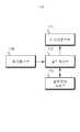
도 1은 이 발명에 따른 해저용 위치확인장치의 일 실시예를 나타내는 블록도이다.
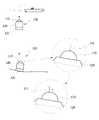
도 2는 도 1의 구성이 적용된 해저용 위치확인장치의 사용상태도이다.
도 3은 이 발명에 따른 해저용 위치확인장치의 다른 일 실시예를 나타내는 블록도이다.
도 4는 이 발명에 따른 해저용 위치확인장치의 또 다른 일 실시예를 나타내는 사시도이다.
도 5는 도 4의 해저용 위치확인장치에 대한 블록도이다.
도 6은 도 4에 나타난 해저용 위치확인장치의 동작을 설명하는 도면이다.
도 7은 이 발명에 따른 해저용 위치확인장치의 또 다른 일 실시예를 나타내는 사시도이다.
도 8은 도 7의 구성이 적용된 해저용 위치확인장치의 사시도이다.
도 9는 도 7 및 도 8에 나타난 밸러스트탱크의 기능을 설명하는 도면이다.
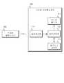
도 10은 이 발명에 따른 해저용 위치확인장치를 이용한 수중 위치확인시스템의 일 실시예를 나타내는 블록도이다.
도 11은 이 발명에 따른 해저용 위치확인장치를 이용한 수중 위치확인시스템의 다른 일 실시예를 나타내는 블록도이다.
도 12는 이 발명에 따른 해저용 위치확인장치를 이용한 수중 위치확인시스템의 또 다른 일 실시예를 나타내는 블록도이다.1 is a block diagram showing an embodiment of an undersea positioning device according to the present invention.
2 is a use state view of a submarine position determining apparatus to which the configuration of FIG. 1 is applied.
3 is a block diagram showing another embodiment of a submarine positioning device according to the present invention.
4 is a perspective view showing still another embodiment of the submarine position determining apparatus according to the present invention.
5 is a block diagram of the submarine positioning device of FIG.
6 is a view for explaining the operation of the submarine positioning device shown in Fig.
7 is a perspective view showing still another embodiment of a submarine positioning device according to the present invention.
8 is a perspective view of a submarine position determining apparatus to which the configuration of FIG. 7 is applied.
Fig. 9 is a view for explaining the function of the ballast tank shown in Figs. 7 and 8. Fig.
FIG. 10 is a block diagram showing an embodiment of an underwater position confirmation system using a submarine positioning device according to the present invention.
FIG. 11 is a block diagram showing another embodiment of an underwater position determination system using a submarine position determining apparatus according to the present invention.
FIG. 12 is a block diagram showing another embodiment of an underwater position determination system using a submarine position determining apparatus according to the present invention.
이 발명에 따른 해저용 위치확인장치 및 이를 이용한 수중 위치확인시스템에 대한 예는 다양하게 적용할 수 있으며, 이하에서는 첨부된 도면을 참조하여 가장 바람직한 실시 예에 대해 설명하기로 한다.The submarine position determining apparatus and the submersible position confirming system using the same according to the present invention can be variously applied. In the following, the most preferred embodiments will be described with reference to the accompanying drawings.
도 1은 이 발명에 따른 해저용 위치확인장치의 일 실시예를 나타내는 블록도이고, 도 2는 도 1의 구성이 적용된 해저용 위치확인장치의 사용상태도이다.FIG. 1 is a block diagram showing an embodiment of an undersea location determining device according to the present invention, and FIG. 2 is a state of use of the undersea location determining device to which the configuration of FIG. 1 is applied.
도 1을 참조하면, 해저용 위치확인장치(100)는 레이저출력모듈(110) 및 베이스구조체(120)를 포함한다.Referring to FIG. 1, a
레이저출력모듈(110)은 해수면을 향하여 상부방향으로 레이저를 출력하는 레이저출력부(111)와, 레이저출력부(111)의 동작을 제어하는 출력제어부(112)를 포함한다.The
이때, 출력제어부(112)는 일정한 패턴에 따라 레이저가 출력되도록 레이저출력부(111)의 동작을 제어할 수 있다. 여기서, 출력되는 레이저의 패턴은 시간적패턴과 상황적패턴을 포함할 수 있으며, 시간적패턴은 출력되는 시간 및 시간간격 등으로 구분될 수 있고, 상황적패턴은 일반 및 위험 등으로 구분될 수 있다.At this time, the
베이스구조체(120)는 상부에 레이저모듈(110)이 구성되어 해저면에 설치된다.The
도 2에 나타난 바와 같이, 베이스구조체(120)가 해저면에 설치되면, 일정한 패턴에 따라 베이스구조체(120)의 상부에 구성된 레이저출력모듈(110)의 레이저출력부(111)로부터 상부방향으로 레이저(L)가 출력되고, 출력된 레이저(L)가 수면에 도달하면 수면상에 위치를 확인할 수 있는 포인트(P)가 표시되어, 해상의 선박에 승선한 선원이 베이스구조체(120)의 위치를 시각적으로 확인할 수 있다.As shown in FIG. 2, when the
따라서, 계측장치의 회수나 수중에서 작업중인 다이버에게 도움을 주기 위해서 추가 다이버가 투입되는 경우, 출력되는 레이저를 따라가면 대상물의 위치를 확인할 수 있게 되는 것이다.Accordingly, when an additional diver is inserted to assist a diver in the course of the recovery of the measurement apparatus or underwater, the position of the object can be confirmed by following the output laser.
이때, 수면상에 표시되는 레이저의 포인트(P)는, 주변환경의 영향(태양이 비추는 낮이나 파도가 높은 경우)으로 인해 시각적인 확인에 어려움이 발생할 수 있다.At this time, the point (P) of the laser displayed on the surface of the water may be difficult to visually confirm due to the influence of the surrounding environment (daytime when the sun is shining or the wave is high).
이러한 어려움을 해결하기 위하여 선박 내의 선원은, 레이저출력부(111)에서 출력된 레이저(L)의 파장만을 통과시키는 필터가 구성된 안경을 이용하여 해당 레이저의 포인트(P)를 쉽게 확인할 수 있다. 여기서, 필터의 종류 및 기능은 레이저(L)의 파장에 따라 당업자에 의해 다양한 변경이 가능하므로, 특정한 것에 한정하지 않음은 물론이다.In order to solve this difficulty, the source in the ship can easily identify the point P of the laser by using a spectacle configured to pass only the wavelength of the laser L output from the
또한, 해수면의 일정영역에 대하여 해당 레이저(L)의 파장을 촬영할 수 있는 카메라로 촬영하고, 영상인식처리를 통해 레이저의 포인트(P)를 확인 및 추적함으로써, 보다 쉽게 대상물의 위치를 확인할 수 있다.Further, the position of the object can be more easily confirmed by photographing with a camera capable of photographing the wavelength of the laser L with respect to a certain area of the sea surface, and confirming and tracking the laser point P through the image recognition process .
결과적으로, 레이저(L)를 확인할 수 있는 필터가 구성된 안경이나 카메라를 통해, 낮과 밤의 시각적 제약은 물론 악조건 상황에서도 대상물의 위치를 용이하게 확인할 수 있다.As a result, the position of the object can be easily confirmed even in a bad condition, as well as day and night visual constraints, through the glasses or the camera having the filter for identifying the laser L.
한편, 베이스구조체(120)는 위치표시기능만을 수행하기 위하여 도 2에 나타난 바와 같이 해저면에 고정설치하거나 수중구조물에 고정설치하는 방식과, 특정 해역에서 작업중인 다이버의 위치를 확인하기 위하여 도 6에 나타난 바와 같이 선상의 해상에서 침강시키는 방식, 그리고 설치 및 회수가 가능하도록 하는 방식으로 적용될 수 있다.2, in order to perform only the position display function, the
더불어, 침강식 및 회수식의 경우, 베이스구조체(120)는 해저용 측정장치가 될 수 있다. 다시 말해, 해저용 측정장치의 상부에 레이저출력모듈(110)을 설치하여 해저용 측정장치의 위치를 확인할 수 있다.In addition, in the case of sedimentation and reclaiming, the
상기와 같은 각 방식에 대하여 하기에서 보다 구체적으로 설명하기로 한다.Each of the above-described systems will be described in more detail below.
도 3은 이 발명에 따른 해저용 위치확인장치의 다른 일 실시예를 나타내는 블록도이다.3 is a block diagram showing another embodiment of a submarine positioning device according to the present invention.
도 3을 참조하면, 레이저출력모듈(110)은 설정정보저장부(113) 및 음파통신부(114)를 더 포함할 수 있다.Referring to FIG. 3, the
설정정보저장부(113)는 동작시간, 단위동작시간 및 출력신호패턴 중 적어도 하나를 포함하는 출력설정정보가 저장된 것으로, 출력설정정보는 수중구조물의 위치를 알려주기 위하여 일정시각 또는 일정시간마다 레이저를 출력하도록 하거나, 수중에서 작업하는 다이버의 상태에 따라 안전 또는 위급상황에 따라 패턴이 달리하여 레이저를 출력하도록 하는 정보를 포함할 수 있다.The setting
이에, 출력제어부(112)는 설정정보저장부(113)에 저장된 출력설정정보에 대응하여 레이저출력부(111)의 동작을 제어할 수 있다.Accordingly, the
음파통신부(114)는 외부에서 전송된 음파신호를 수신하는 것으로, 하기에 설명될 휴대용 음파송신기로부터 전송되는 음파신호 등을 수신할 수 있으며, 당업자의 요구에 따라 설정정보저장부(113)에 저장된 출력설정정보의 갱신을 위한 음파신호, 레이저출력모듈(110)의 동작제어를 위한 음파신호 등도 수신할 수 있다.The sound
이에, 출력제어부(112)는 음파통신부(114)로 수신된 음파신호를 분석하고, 분석결과에 따른 출력설정정보를 호출하여 레이저출력부(112)의 동작을 제어할 수 있다.The
이상에서 설명된 해저용 위치확인장치는 일정한 위치의 해저면이나, 계측장치 및 해저구조물 등에 고정설치되어, 대상물의 위치를 일정시간마다 해수면에 표시하여 시각적으로 알려주거나, 수중에서 작업중인 다이버의 위치 및 상태를 해상의 선박에서 확인할 수 있도록 하기 위해 사용될 수 있다.The undersea positioning device described above is fixedly installed on a seabed surface at a predetermined position, a measurement device, a seabed structure, etc., and visually informs the position of the object by displaying it on the sea surface at certain time intervals, And status to be visible at sea.
이하에서는, 상기의 해저용 위치확인장치가 설치되지 않은 해역에서, 긴급한 수중 작업시 계측장치의 위치를 확인하고 용이하게 회수할 수 있음은 물론, 다이버의 위치 및 안전을 보장할 수 있는 해저용 위치확인장치에 대해 살펴보기로 한다.Hereinafter, the position of the measuring device can be confirmed and recovered easily in an emergency underwater operation in a sea area where the above-mentioned submarine positioning device is not installed, and furthermore, Let's take a look at the verification device.
도 4는 이 발명에 따른 해저용 위치확인장치의 또 다른 일 실시예를 나타내는 사시도이고, 도 5는 도 4의 해저용 위치확인장치에 대한 블록도이며, 도 6은 도 4에 나타난 해저용 위치확인장치의 동작을 설명하는 도면이다.FIG. 4 is a perspective view showing still another embodiment of the submarine positioning device according to the present invention, FIG. 5 is a block diagram of the submarine positioning device of FIG. 4, Fig. 8 is a diagram for explaining the operation of the confirmation device.
도 4를 참조하면, 베이스구조체(120)를 자유낙하방식으로 하강시키기 위한 중량체(130)가 베이스구조체(120)의 하부에 구성될 수 있다.Referring to FIG. 4, a
이에, 도 6에 나타난 바와 같이 해상에 정박중인 선박(미부호)으로부터 해저용 위치확인장치를 수중으로 투입하면, 투입된 해저용 위치확인장치는 중량체(130)에 의해 해저면으로 자유낙하할 수 있다.6, when the submarine positioning device is submerged in water from a vessel (not shown) that is docked in the sea, the submarine positioning device that has been submerged can freely fall down to the seafloor by the
한편, 레이저출력모듈(110)에는 도 5에 나타난 바와 같이 자이로스코프센서(115)가 탑재될 수 있으며, 출력제어부(112)는 자이로스크포센서(115)로부터 수신되는 감지신호에 의해 레이저출력모듈(110)의 하강이 중단되면, 베이스구조체(120)가 해저면에 위치한 것으로 판단할 수 있다.5, the
여기서, 자이로스코프센서(115)는 PCB형태(예를 들어, 나선형상으로 패터닝된 CPB를 중첩한 다중구조)와 같이, 저가이면서도 이 발명의 목적을 달성하기에 충분한 정도의 구성으로 제작됨이 바람직하다.Here, it is preferable that the
도 5에 나타난 바와 같이, 레이저출력모듈(110)은 자이로스코프센서(115)와 더불어, 자세제어부(116) 및 RP구동부(117)를 포함할 수 있다.5, the
자이로스코프센서(115)는 베이스구조체(120)가 해저면에 위치하게 되면, 베이스구조체(120)의 기울기를 확인하여 레이저출력부(111)의 방향을 감지할 수 있다.The
자세제어부(116)는 자이로스코프센서(115)에서 감지된 베이스구조체(120)의 기울기에 기초하여 RP구동부(117)를 제어하여 레이저출력부(111)의 방향이 상부를 향하도록 롤링(Rolling) 및 피칭(Pitching)을 제어할 수 있다. 예를 들어, 자이로스코프센서(115)의 감지신호(측정데이터)에 의해 베이스구조체(120)가 해저면에 위치한 것을 확인한 출력제어부(112)가 자세제어부(116)에 레이저출력부(111)의 방향 및 제어를 수행하도록 요청할 수 있다.The
구체적으로, 해저용 위치확인장치가 하강하는 과정에서 베이스구조체(120)의 흔들림을 자이로스코프센서(115)가 감지하면, 자세제어부(116)는 자이로스코프센서(115)의 측정데이터에 기초하여 레이저출력부(111)의 레이저 출력방향이 상부방향을 유지하도록 자세보정제어신호를 생성할 수 있다.Specifically, when the
RP구동부(117)는 자세보정제어신호에 대응하여 레이저출력부(111)가 상부방향을 향하도록 레이저출력모듈(110)의 롤링(Rolling) 및 피칭(Pitching) 중 적어도 하나로 회동시킬 수 있다. 이를 위하여, 레이저출력모듈(110)이 베이스구조체(120)에 롤링 및 피칭이 가능하도록 결합될 수 있으며, 이와 같은 결합구성은 당업자의 요구에 따라 다양하게 변형될 수 있으므로 특정한 것에 한정하지 않음은 물론이다.The
상기와 같이, 자세제어부(116)의 제어에 의해 레이저출력모듈(110)의 레이저출력부(111)가 상부방향을 향하도록 하는 제어가 완료되면, 자세제어부(116)는 출력제어부(112)에 자세보정완료신호를 전송할 수 있으며, 출력제어부(112)는 자세보정완료신호가 수신되면 레이저출력부(111)의 레이저출력을 제어할 수 있다.The control of the
한편, 레이저출력모듈(110)에는 음파통신부(114)가 구성되어 있는 바, 이하에서는 음파통신부(114)를 통해 원격으로 이 발명의 해저용 위치확인장치를 회수할 수 있는 방법에 대해 살펴보기로 한다.The
도 7은 이 발명에 따른 해저용 위치확인장치의 또 다른 일 실시예를 나타내는 사시도이고, 도 8은 도 7의 구성이 적용된 해저용 위치확인장치의 사시도이며, 도 9는 도 7 및 도 8에 나타난 밸러스트탱크의 기능을 설명하는 도면이다.8 is a perspective view of a submarine position determining apparatus to which the configuration of FIG. 7 is applied, and FIG. 9 is a perspective view of the submarine position determining apparatus of FIG. Fig. 3 is a view illustrating the function of the ballast tank shown in Fig.
도 7을 참조하면, 베이스구조체(120)에는 제1 및 제2 롤링밸러스트탱크(121, 122)와 제1 및 제2 피칭팰러스트탱크(123, 124)가, 수평면에 대한 두 직교축(X, Y)을 따라 나란히 배치될 수 있다.Referring to FIG. 7, first and second rolling
이에, 도 9에 나타난 바와 같이, 나란히 배치된 한 쌍의 롤링밸러스트탱크(121, 122) 중 적어도 하나에 저장된 밸러스트수에 대한 유입 및 배출량을 제어하면, X축에 대한 베이스구조체(120)의 회동을 제어할 수 있다. 물론, 도 9에 나타난 방법과 동일한 방법으로 피칭팰러스트탱크(123, 124)에 저장된 밸러스트수를 제어하여 Y축에 대한 회동을 제어할 수 있음은 당연하다.9, by controlling the inflow and outflow amount to the ballast water stored in at least one of the pair of rolling
따라서, 자세제어부(116)는 자이로스코프센서(115)의 측정데이터에 기초하여 생성된 자세보정제어신호를 통해, 해당 밸러스트탱크를 제어하여 베이스구조체(120) 및 레이저출력모듈(110)을 롤링 및 피칭시킬 수 있다. 여기서, 레이저출력모듈(110) 및 베이스구조체(120)가 고정되도록 구성됨은 물론이다.Therefore, the
또한, 자세제어부(116)는 롤링밸러스트탱크(121, 122) 및 피칭밸러스트탱크(123, 124)를 동시에 제어하여, 레이저출력모듈(110)을 포함하는 해저용 위치확인장치(100)를 상승 또는 하강시킬 수 있음은 당연하다.The
이하에서는, 상기에서 설명된 해저용 위치확인장치를 이용하는 방법에 대해 구체적으로 살펴보기로 한다.Hereinafter, a method of using the submarine position determining apparatus described above will be described in detail.
도 10은 이 발명에 따른 해저용 위치확인장치를 이용한 수중 위치확인시스템의 일 실시예를 나타내는 블록도이다.FIG. 10 is a block diagram showing an embodiment of an underwater position confirmation system using a submarine positioning device according to the present invention.
도 10을 참조하면, 수중위치확인시스템은 휴대용 음파송신기(300) 및 해저용 위치확인장치(100)를 포함할 수 있다.Referring to FIG. 10, the underwater positioning system may include a portable
휴대용 음파송신기(300)는 위치확인신호를 음파신호로 송출하는 것으로, 수중에서 작업하는 다이버가 휴대하여 자신의 위치를 해상의 선박(보다 정확히는 선박에 승선한 선원)에 알리거나, 위급상황시 도움을 요청할 수 있다.The portable
또한, 휴대용 음파송신기(300)는 다어버의 신체상태를 감지할 수 있는 생체센서(도시하지 않음)를 포함할 수 있으며, 다이버가 스스로 위급상황을 알리지 못하는 경우에 자동으로 해당 위치를 선박에 알릴 수 있다.In addition, the portable
해저용 위치확인장치(100)는 해저면에 설치되고 휴대용 음파송신기(300)로부터 송출된 음파신호를 수신하여 위치확인신호를 확인하고, 위치확인신호에 대응하여 해수면을 향하여 상부방향으로 레이저를 출력한다.The
이하에서는, 다이버가 작업하는 영역에 복수개의 해저용 위치확인장치(100)를 설치하여, 휴대용 음파송신기(300)와 가장 인접한 해저용 위치확인장치(100)가 현재 다이버의 위치를 해수면으로 알려줄 수 있는 방법에 대해 살펴보기로 한다.Hereinafter, a plurality of
도 11은 이 발명에 따른 해저용 위치확인장치를 이용한 수중 위치확인시스템의 다른 일 실시예를 나타내는 블록도이다.FIG. 11 is a block diagram showing another embodiment of an underwater position determination system using a submarine position determining apparatus according to the present invention.
도 11을 참조하면, 해저용 위치확인장치(100)는 해저면에 일정간격으로 설치되어, ad-hoc 통신방식의 센서네트워크 기반으로 통신을 수행할 수 있다.Referring to FIG. 11, the
이에, 복수개의 해저용 위치확인장치(100) 중 휴대용 음파송신기(300)의 위치확인신호를 수신한 해저용 위치확인장치(100)들은, 위치확인신호의 수신시간정보를 서로 교환하여 비교하고, 위치확인신호의 수신시간이 가장 빠른 해저용 위치확인장치가 설정된 패턴에 대응하여 레이저를 출력할 수 있다.Thus, the
따라서, 해상의 선박에서는 수중에서 작업중인 다이버의 위치를 보다 정확히 확인할 수 있다.Therefore, it is possible to more accurately confirm the position of a diver in operation in a marine vessel.
한편, 선박을 홀로 운행하여 특정영역에서 작업을 하는 경우, 다이버의 위급상황을 선박에서 파악할 수 없게 된다.On the other hand, when the ship is operated solely and working in a specific area, the emergency situation of the diver can not be grasped by the ship.
이하에서는, 선박에서 수중의 다이버에게 도움을 줄 수 없는 경우 및 이와 유사한 상황에서, 원격지에서 다이버의 위험상황에 대해 신속하게 대처할 수 있는 방법에 대해 살펴보기로 한다.Hereinafter, a method for quickly responding to a dangerous situation of a diver at a remote place in a case where a vessel can not provide assistance to a diver in the water and a similar situation, will be described.
도 12는 이 발명에 따른 해저용 위치확인장치를 이용한 수중 위치확인시스템의 또 다른 일 실시예를 나타내는 블록도이다.FIG. 12 is a block diagram showing another embodiment of an underwater position determination system using a submarine position determining apparatus according to the present invention.
도 12를 참조하면, 이 발명의 수중 위치확인시스템은 해저용 위치확인장치(100)와 통신을 수행하는 원격감시서버(400)를 더 포함할 수 있다.Referring to FIG. 12, the underwater location system of the present invention may further include a
그리고, 휴대용 음파송신기(300)에서 출력되는 위치확인신호는, 정상상태 위치확인신호, 위험상태 위치확인신호 및 응급상태 위치확인신호 중 적어도 하나를 포함할 수 있다.The position confirmation signal output from the portable
이에, 해저용 위치확인장치(100)는, 수신된 위치확인신호를 분석하여, 각 상태별로 설정된 패턴에 대응하여 상부방향으로 레이저를 출력함과 동시에, 위험상태 위치확인신호 및 응급상태 위치확인신호 중 적어도 하나가 확인되면, 원격감시서버(400)에 해당 상황을 통보할 수 있다.Thus, the seam
원격감시서버(400)는, 해저용 위치확인장치(100)로부터 위험상태 위치확인신호 및 응급상태 위치확인신호 중 적어도 하나를 수신하면, 해당 해저용 위치확인장치(100)가 설치된 수역에서 위험상황 및 응급상황이 발생된 것으로 판단하고, 해당 수역에 위치하는 선박 및 대응기관서버(예를 들어, 해난구조센터에서 운용하는 서버 등)에 해당 상황에 따른 대응을 요청할 수 있다.When the
이에, 원격감시서버(400)로부터 위험상황에 따른 요청을 수신한 선박은, 해당 수역으로 이동하여, 해저용 위치확인장치(100)에서 해수면으로 출력된 레이저를 시각적으로 확인하고, 위험상황에 처한 다이버를 신속하게 구출할 수 있다.Accordingly, the ship which has received the request according to the dangerous situation from the
한편, 육상에서 사용하는 무선통신방식을 수중에서 이용하게 되면 신호의 감쇄가 매우 크게 발생하게 되므로, 수중에서는 주로 음파를 이용한 통신방식을 이용함이 바람직하다.On the other hand, if the wireless communication system used in the land is used in water, the attenuation of the signal becomes very large. Therefore, it is preferable to use a communication system using mainly a sound wave in the water.
이러한 음파통신은 육상에서도 이용이 가능하기는 하나, 육상에서는 상용화되어 널리 보급된 무선통신방식을 이용하는 것이 보다 효율적일 수 있다.Although such a sound wave communication can be used on land, it may be more efficient to use a wireless communication system that is widely used and commercially available on the land.
이에, 이 발명의 수중 위치확인시스템은, 도 12에 나타난 바와 같이 해저용 위치확인장치(100)로부터 수중 음파통신으로 위치확인신호를 수신하고, 수신된 위치확인신호를 육상 무선통신용 데이터로 변환하여 원격감시서버(400)에 전송하는 중계장치(500)를 더 포함할 수 있다.Thus, the underwater position determination system of the present invention receives the position confirmation signal from the submarine
중계장치(500)는 해저용 위치확인장치(100)와 유무선으로 통신하는 부유체 또는 다이버가 승선하여 해당 해역으로 이동하여 정박중인 선박 등을 포함할 수 있다.The
따라서, 다이버가 휴대용 음파송신기를 이용하여 위급상황시 자신의 위치를 신속하게 알려줌으로써, 해양에서 발생되는 사고에 대하여 신속한 대처가 가능한 장점이 있다.Accordingly, the diver can quickly respond to an accident occurring in the ocean by quickly informing the user of his / her position in an emergency using a portable sound wave transmitter.
이상에서 이 발명에 의한 해저용 위치확인장치 및 이를 이용한 수중 위치확인시스템에 대하여 설명하였다. 이러한 이 발명의 기술적 구성은 이 발명이 속하는 기술분야의 당업자가 이 발명의 그 기술적 사상이나 필수적 특징을 변경하지 않고서 다른 구체적인 형태로 실시될 수 있다는 것을 이해할 수 있을 것이다.The submarine position determining apparatus and the submersible position identifying system using the same according to the present invention have been described above. It will be understood by those skilled in the art that various changes in form and details may be made therein without departing from the spirit and scope of the invention as defined by the appended claims.
그러므로 이상에서 기술한 실시예들은 모든 면에서 예시적인 것이며, 한정적인 것이 아닌 것으로서 이해되어야 한다.
It is to be understood, therefore, that the embodiments described above are in all respects illustrative and not restrictive.
100 : 해저용 위치확인장치
110 : 레이저출력모듈111 : 레이저출력부
112 : 출력제어부113 : 설정정보저장부
114 : 음파통신부115 : 자이로스코프센서
116 : 자세제어부117 : RP구동부
120 : 베이스구조체130 : 중량체
121 : 제1 롤링밸러스트탱크122 : 제2 롤링밸러스트탱크
123 : 제1 피칭밸러스트탱크124 : 제2 피칭밸러스트탱크
300 : 휴대용 음파송신기400 : 원격감시서버
500 : 중계장치100: Submarine positioning device
110: laser output module 111: laser output part
112: output control section 113: setting information storage section
114: sound wave communication unit 115: gyroscope sensor
116: attitude control unit 117: RP driving unit
120: base structure 130: weight
121: first rolling ballast tank 122: second rolling ballast tank
123: first pitching ballast tank 124: second pitching ballast tank
300: portable sound wave transmitter 400: remote monitoring server
500: Relay device
Claims (11)
Translated fromKorean일정한 패턴에 따라 레이저가 출력되도록 상기 레이저출력부의 동작을 제어하는 출력제어부와,
동작시간, 단위동작시간 및 출력신호패턴 중 적어도 하나를 포함하는 출력설정정보가 저장된 설정정보저장부를 포함하는 레이저출력모듈; 및
해저면에 설치되고 상부에 상기 레이저출력모듈이 구성되는 베이스구조체;를 포함하고,
상기 출력제어부는,
상기 설정정보저장부에 저장된 출력설정정보에 대응하여 상기 레이저출력부의 동작을 제어하는 것을 특징으로 하는 해저용 위치확인장치.
A laser output unit for outputting the laser in the upward direction toward the sea surface,
An output control unit for controlling the operation of the laser output unit to output a laser according to a predetermined pattern;
A laser output module including a setting information storage unit in which output setting information including at least one of an operation time, a unit operation time, and an output signal pattern is stored; And
And a base structure installed on the sea floor and having the laser output module formed thereon,
Wherein the output control unit comprises:
Wherein the control unit controls the operation of the laser output unit according to the output setting information stored in the setting information storage unit.
상기 레이저출력모듈은,
외부에서 전송된 음파신호를 수신하는 음파수신부;를 더 포함하고,
상기 출력제어부는,
수신된 음파신호를 분석하고, 분석결과에 따른 출력설정정보를 호출하여 상기 레이저출력부의 동작을 제어하는 것을 특징으로 하는 해저용 위치확인장치.
The method according to claim 1,
The laser output module includes:
And a sound wave receiver for receiving an externally transmitted sound wave signal,
Wherein the output control unit comprises:
Analyzes the received sound wave signal, and calls the output setting information according to the analysis result to control the operation of the laser output unit.
상기 베이스구조체의 하부에는,
상기 베이스구조체를 자유낙하방식으로 하강시키는 중량체가 구성된 것을 특징으로 하는 해저용 위치확인장치.
The method according to claim 1 or 3,
In the lower portion of the base structure,
And a weight for descending the base structure in a free fall manner.
상기 레이저출력모듈은,
상부방향을 기준으로 상기 레이저출력모듈의 흔들림을 측정하는 자이로스코프센서;
상기 자이로스코프센서의 측정데이터에 기초하여 상기 레이저출력부의 레이저 출력방향이 상부방향을 유지하도록 자세보정제어신호를 생성하는 자세제어부; 및
상기 자세제어부에서 생성된 자세보정제어신호에 대응하여 상기 레이저출력모듈을 롤링(Rolling) 및 피칭(Pitching) 중 적어도 하나로 회동시키는 RP구동부;를 더 포함하는 것을 특징으로 하는 해저용 위치확인장치.
5. The method of claim 4,
The laser output module includes:
A gyroscope sensor for measuring a shake of the laser output module with respect to an upper direction;
An attitude control unit for generating an attitude correction control signal so that a laser output direction of the laser output unit maintains an upward direction based on measurement data of the gyroscope sensor; And
And an RP driving unit for rotating the laser output module in at least one of rolling and pitching in accordance with the attitude correction control signal generated by the attitude control unit.
상기 레이저출력모듈은,
상부방향을 기준으로 상기 레이저출력모듈의 흔들림을 측정하는 자이로스코프센서; 및
상기 자이로스코프센서의 측정데이터에 기초하여 상기 레이저출력부의 레이저 출력방향이 상부방향을 유지하도록 자세보정제어신호를 생성하는 자세제어부;를 더 포함하고,
상기 베이스구조체는,
상기 자세제어부에서 생성된 자세보정제어신호에 대응하여 상기 레이저출력모듈을 롤링(Rolling)시키는 롤링밸러스트탱크; 및
상기 자세제어부에서 생성된 자세보정제어신호에 대응하여 상기 레이저출력모듈을 피칭(Pitching)시키는 피칭밸러스트탱크;를 더 포함하는 것을 특징으로 하는 해저용 위치확인장치.
The method according to claim 1 or 3,
The laser output module includes:
A gyroscope sensor for measuring a shake of the laser output module with respect to an upper direction; And
And an attitude control unit for generating an attitude correction control signal so that a laser output direction of the laser output unit maintains an upward direction based on measurement data of the gyroscope sensor,
The base structure may include:
A rolling ballast tank for rolling the laser output module corresponding to the attitude correction control signal generated by the attitude control unit; And
And a pitching ballast tank for pitching the laser output module corresponding to the attitude correction control signal generated by the attitude control unit.
상기 자세제어부는,
상기 롤링밸러스트탱크 및 피칭밸러스트탱크를 동시에 제어하여 상기 레이저출력모듈을 상승 또는 하강시키는 것을 특징으로 하는 해저용 위치확인장치.
The method according to claim 6,
The posture control unit,
Wherein the control unit simultaneously controls the rolling ballast tank and the pitching ballast tank to raise or lower the laser output module.
해저면에 설치되고 상기 휴대용 음파송신기로부터 송출된 음파신호를 수신하여 위치확인신호를 확인하고, 상기 위치확인신호에 대응하여 해수면을 향하여 상부방향으로 레이저를 출력하는 해저용 위치확인장치; 및
상기 해저용 위치확인장치와 통신을 수행하는 원격감시서버;를 포함하고,
상기 위치확인신호는,
정상상태 위치확인신호, 위험상태 위치확인신호 및 응급상태 위치확인신호 중 적어도 하나를 포함하고,
상기 해저용 위치확인장치는,
수신된 위치확인신호를 분석하여, 각 상태별로 설정된 패턴에 대응하여 상부방향으로 레이저를 출력하고,
위험상태 위치확인신호 및 응급상태 위치확인신호 중 적어도 하나가 확인되면, 상기 원격감시서버에 해당 상황을 통보하며,
상기 원격감시서버는,
상기 해저용 위치확인장치가 설치된 수역에서 위험상황 및 응급상황이 발생됨을 통보받으면, 해당 수역에 위치하는 선박 및 대응기관서버에 해당 상황에 따른 대응을 요청하는 것을 특징으로 하는 수중 위치확인시스템.
A portable sound wave transmitter for transmitting a position confirmation signal as a sound wave signal;
A submarine positioning device installed on the sea floor for receiving a sound wave signal transmitted from the portable sound wave transmitter to confirm the position confirmation signal and outputting the laser in the upward direction toward the sea surface in response to the position confirmation signal; And
And a remote monitoring server for performing communication with the submarine positioning apparatus,
The position confirmation signal may include:
At least one of a steady state position determination signal, a critical state position determination signal, and an emergency state position determination signal,
The submarine position determining device comprises:
Analyzes the received position confirmation signal, and outputs the laser in the upward direction corresponding to the pattern set for each state,
When the at least one of the critical state position confirmation signal and the emergency state position confirmation signal is confirmed, notifies the remote monitoring server of the status,
The remote monitoring server comprises:
Wherein when a notification of a dangerous situation and an emergency situation occurs in a water body in which the submarine positioning device is installed, a request is made to the ship and the corresponding agency server located in the watery location for a response according to the situation.
상기 해저용 위치확인장치는 복수개가 해저면에 일정간격으로 설치되어, ad-hoc 통신방식의 센서네트워크 기반으로 통신을 수행하며,
복수개의 해저용 위치확인장치 중 상기 위치확인신호를 수신한 해저용 위치확인장치들은, 상기 위치확인신호의 수신시간정보를 서로 교환하여 비교하고, 상기 위치확인신호의 수신시간이 가장 빠른 해저용 위치확인장치가 설정된 패턴에 대응하여 레이저를 출력하는 것을 특징으로 하는 수중 위치확인시스템.
9. The method of claim 8,
A plurality of submarine positioning apparatuses are installed at regular intervals on the sea floor to perform communication based on a sensor network of an ad-hoc communication system,
The submarine positioning apparatuses receiving the position confirmation signal among the plurality of submarine positioning apparatus exchange the reception time information of the position confirmation signal with each other and compare the reception time information of the positioning information with the submarine position And the confirmation device outputs a laser corresponding to the pattern set.
상기 해저용 위치확인장치로부터 수중 음파통신으로 상기 위치확인신호를 수신하고, 수신된 위치확인신호를 육상 무선통신용 데이터로 변환하여 상기 원격감시서버에 전송하는 중계장치를 더 포함하는 것을 특징으로 하는 수중 위치확인시스템.10. The method of claim 9,
Further comprising a relay device for receiving the position confirmation signal from underwater sonar communication device by means of underwater acoustic communication and converting the received position confirmation signal into data for terrestrial radio communication and transmitting the data to the remote monitoring server Positioning system.
Priority Applications (1)
| Application Number | Priority Date | Filing Date | Title |
|---|---|---|---|
| KR1020140082891AKR101462100B1 (en) | 2014-07-03 | 2014-07-03 | Positioning device for seabed and underwater positioning system using the same |
Applications Claiming Priority (1)
| Application Number | Priority Date | Filing Date | Title |
|---|---|---|---|
| KR1020140082891AKR101462100B1 (en) | 2014-07-03 | 2014-07-03 | Positioning device for seabed and underwater positioning system using the same |
Publications (1)
| Publication Number | Publication Date |
|---|---|
| KR101462100B1true KR101462100B1 (en) | 2014-11-17 |
Family
ID=52290657
Family Applications (1)
| Application Number | Title | Priority Date | Filing Date |
|---|---|---|---|
| KR1020140082891AExpired - Fee RelatedKR101462100B1 (en) | 2014-07-03 | 2014-07-03 | Positioning device for seabed and underwater positioning system using the same |
Country Status (1)
| Country | Link |
|---|---|
| KR (1) | KR101462100B1 (en) |
Cited By (4)
| Publication number | Priority date | Publication date | Assignee | Title |
|---|---|---|---|---|
| KR20170071439A (en)* | 2015-12-15 | 2017-06-23 | 김석문 | Sea Floor Structure Location Setting System, Flying Apparatus and Location Setting Method |
| WO2018225984A1 (en)* | 2017-06-08 | 2018-12-13 | (주)한국해양기상기술 | Method and server for determining dangerous situation at sea |
| KR20230071407A (en)* | 2021-11-16 | 2023-05-23 | 주식회사 엠에이치넷 | System for providing underwater environment media service |
| KR20250098241A (en) | 2023-12-22 | 2025-07-01 | 한승욱 | System for Detecting Lcation of Underwater Moving Obeject |
Citations (3)
| Publication number | Priority date | Publication date | Assignee | Title |
|---|---|---|---|---|
| KR100601922B1 (en)* | 2003-10-08 | 2006-07-20 | 주식회사 씨스캔 | Fish detection device using personal portable terminal |
| JP3994383B2 (en)* | 2002-11-18 | 2007-10-17 | アジア海洋株式会社 | Vertical position specifying device and vertical position specifying method |
| JP2011196955A (en)* | 2010-03-23 | 2011-10-06 | Japan Agengy For Marine-Earth Science & Technology | Laser transmission/reception system for measuring underwater distance, laser stick, and method of measuring underwater distance |
- 2014
- 2014-07-03KRKR1020140082891Apatent/KR101462100B1/ennot_activeExpired - Fee Related
Patent Citations (4)
| Publication number | Priority date | Publication date | Assignee | Title |
|---|---|---|---|---|
| JP3994383B2 (en)* | 2002-11-18 | 2007-10-17 | アジア海洋株式会社 | Vertical position specifying device and vertical position specifying method |
| KR100601922B1 (en)* | 2003-10-08 | 2006-07-20 | 주식회사 씨스캔 | Fish detection device using personal portable terminal |
| JP2011196955A (en)* | 2010-03-23 | 2011-10-06 | Japan Agengy For Marine-Earth Science & Technology | Laser transmission/reception system for measuring underwater distance, laser stick, and method of measuring underwater distance |
| JP5212745B2 (en)* | 2010-03-23 | 2013-06-19 | 独立行政法人海洋研究開発機構 | Laser transmission / reception system for underwater distance measurement |
Cited By (6)
| Publication number | Priority date | Publication date | Assignee | Title |
|---|---|---|---|---|
| KR20170071439A (en)* | 2015-12-15 | 2017-06-23 | 김석문 | Sea Floor Structure Location Setting System, Flying Apparatus and Location Setting Method |
| KR101944595B1 (en) | 2015-12-15 | 2019-01-30 | 김석문 | Sea Floor Structure Location Setting System, Flying Apparatus and Location Setting Method |
| WO2018225984A1 (en)* | 2017-06-08 | 2018-12-13 | (주)한국해양기상기술 | Method and server for determining dangerous situation at sea |
| KR20230071407A (en)* | 2021-11-16 | 2023-05-23 | 주식회사 엠에이치넷 | System for providing underwater environment media service |
| KR102611414B1 (en) | 2021-11-16 | 2023-12-08 | 주식회사 엠에이치넷 | System for providing underwater environment media service |
| KR20250098241A (en) | 2023-12-22 | 2025-07-01 | 한승욱 | System for Detecting Lcation of Underwater Moving Obeject |
Similar Documents
| Publication | Publication Date | Title |
|---|---|---|
| KR101736381B1 (en) | Method of real-time operational ocean monitoring system using Drone equipped with an automatic winch | |
| JP4197872B2 (en) | Device for deploying a load at an underwater target location with improved accuracy and method for controlling such a device | |
| EP3188959B1 (en) | Mooring system and mooring buoy | |
| KR101407158B1 (en) | lifesaving system and method to save thereof | |
| KR101462100B1 (en) | Positioning device for seabed and underwater positioning system using the same | |
| KR101934532B1 (en) | Transmitter and router for rescuing sufferer of sea | |
| KR101549513B1 (en) | System and Method for Preventing Collision of Vessel and Recording using Augmented Reality | |
| KR102007849B1 (en) | System and method for supporting ship entering and leaving port using 3d lidar mounted on unmanned aerial vehicle | |
| KR101609723B1 (en) | Monitoring system of real timeocean current | |
| JP7023494B2 (en) | Wave observation notification system | |
| US10093400B2 (en) | Systems and methods for handling a man overboard situation | |
| CN110865569B (en) | Electronic equipment, system and control method applied to diving | |
| KR101686043B1 (en) | Vessel collision monitoring system of marine structure | |
| KR102170351B1 (en) | rescue system and method for a man overboard person | |
| KR20180042655A (en) | Ship emergency response system | |
| KR101043055B1 (en) | Ultrasonic Vessel Route Guidance System and Apparatus | |
| KR101653754B1 (en) | Method, server and computer-readable recording media for providing maritime safety service by using information on danger area | |
| JP2019177833A (en) | Underwater equipment recovery method, and underwater equipment recovery system | |
| CN118884501B (en) | Marine personnel position tracking system based on satellite communication | |
| JP2013141923A (en) | Grounding position information transmitting device, and grounding position detection system | |
| JP6241995B2 (en) | Diver information acquisition method and diver information acquisition system | |
| KR101647753B1 (en) | Sonar and Motion Compensation Apparatus of Sonar | |
| JP2023050664A (en) | Collection support device, collection support system and program | |
| KR102633185B1 (en) | A Mayday System for Detecting a Drowned Man and Alarming Using A Mobile Device | |
| JPH1111396A (en) | Fallen person rescue support system |
Legal Events
| Date | Code | Title | Description |
|---|---|---|---|
| PA0109 | Patent application | St.27 status event code:A-0-1-A10-A12-nap-PA0109 | |
| PA0201 | Request for examination | St.27 status event code:A-1-2-D10-D11-exm-PA0201 | |
| PA0302 | Request for accelerated examination | St.27 status event code:A-1-2-D10-D17-exm-PA0302 St.27 status event code:A-1-2-D10-D16-exm-PA0302 | |
| D13-X000 | Search requested | St.27 status event code:A-1-2-D10-D13-srh-X000 | |
| D14-X000 | Search report completed | St.27 status event code:A-1-2-D10-D14-srh-X000 | |
| E902 | Notification of reason for refusal | ||
| PE0902 | Notice of grounds for rejection | St.27 status event code:A-1-2-D10-D21-exm-PE0902 | |
| E13-X000 | Pre-grant limitation requested | St.27 status event code:A-2-3-E10-E13-lim-X000 | |
| P11-X000 | Amendment of application requested | St.27 status event code:A-2-2-P10-P11-nap-X000 | |
| P13-X000 | Application amended | St.27 status event code:A-2-2-P10-P13-nap-X000 | |
| E701 | Decision to grant or registration of patent right | ||
| PE0701 | Decision of registration | St.27 status event code:A-1-2-D10-D22-exm-PE0701 | |
| GRNT | Written decision to grant | ||
| PR0701 | Registration of establishment | St.27 status event code:A-2-4-F10-F11-exm-PR0701 | |
| PR1002 | Payment of registration fee | St.27 status event code:A-2-2-U10-U11-oth-PR1002 Fee payment year number:1 | |
| PG1601 | Publication of registration | St.27 status event code:A-4-4-Q10-Q13-nap-PG1601 | |
| P22-X000 | Classification modified | St.27 status event code:A-4-4-P10-P22-nap-X000 | |
| FPAY | Annual fee payment | Payment date:20171110 Year of fee payment:4 | |
| PR1001 | Payment of annual fee | St.27 status event code:A-4-4-U10-U11-oth-PR1001 Fee payment year number:4 | |
| FPAY | Annual fee payment | Payment date:20181106 Year of fee payment:5 | |
| PR1001 | Payment of annual fee | St.27 status event code:A-4-4-U10-U11-oth-PR1001 Fee payment year number:5 | |
| FPAY | Annual fee payment | Payment date:20191105 Year of fee payment:6 | |
| PR1001 | Payment of annual fee | St.27 status event code:A-4-4-U10-U11-oth-PR1001 Fee payment year number:6 | |
| PR1001 | Payment of annual fee | St.27 status event code:A-4-4-U10-U11-oth-PR1001 Fee payment year number:7 | |
| R18-X000 | Changes to party contact information recorded | St.27 status event code:A-5-5-R10-R18-oth-X000 | |
| P14-X000 | Amendment of ip right document requested | St.27 status event code:A-5-5-P10-P14-nap-X000 | |
| P14-X000 | Amendment of ip right document requested | St.27 status event code:A-5-5-P10-P14-nap-X000 | |
| PR1001 | Payment of annual fee | St.27 status event code:A-4-4-U10-U11-oth-PR1001 Fee payment year number:8 | |
| PC1903 | Unpaid annual fee | St.27 status event code:A-4-4-U10-U13-oth-PC1903 Not in force date:20221111 Payment event data comment text:Termination Category : DEFAULT_OF_REGISTRATION_FEE | |
| PC1903 | Unpaid annual fee | St.27 status event code:N-4-6-H10-H13-oth-PC1903 Ip right cessation event data comment text:Termination Category : DEFAULT_OF_REGISTRATION_FEE Not in force date:20221111 |