KR101459152B1 - Data processing apparatus and method - Google Patents
Data processing apparatus and methodDownload PDFInfo
- Publication number
- KR101459152B1 KR101459152B1KR1020080107304AKR20080107304AKR101459152B1KR 101459152 B1KR101459152 B1KR 101459152B1KR 1020080107304 AKR1020080107304 AKR 1020080107304AKR 20080107304 AKR20080107304 AKR 20080107304AKR 101459152 B1KR101459152 B1KR 101459152B1
- Authority
- KR
- South Korea
- Prior art keywords
- address
- bits
- symbol
- ldpc
- code
- Prior art date
- Legal status (The legal status is an assumption and is not a legal conclusion. Google has not performed a legal analysis and makes no representation as to the accuracy of the status listed.)
- Active
Links
- 238000000034methodMethods0.000titleclaimsabstractdescription253
- 238000012545processingMethods0.000titleclaimsabstractdescription117
- 239000011159matrix materialSubstances0.000claimsabstractdescription342
- 230000008569processEffects0.000claimsabstractdescription83
- 238000013507mappingMethods0.000claimsabstractdescription35
- 230000000694effectsEffects0.000claimsabstractdescription4
- 230000015654memoryEffects0.000claimsdescription215
- 238000006467substitution reactionMethods0.000claimsdescription78
- 230000001172regenerating effectEffects0.000claims2
- 230000001419dependent effectEffects0.000claims1
- 230000001131transforming effectEffects0.000claims1
- 230000000875corresponding effectEffects0.000description103
- 238000010586diagramMethods0.000description40
- 238000004891communicationMethods0.000description34
- 238000004364calculation methodMethods0.000description33
- 125000004122cyclic groupChemical group0.000description31
- 238000013500data storageMethods0.000description17
- 238000004088simulationMethods0.000description13
- 238000012937correctionMethods0.000description12
- 238000004458analytical methodMethods0.000description9
- 230000005540biological transmissionEffects0.000description7
- 238000004422calculation algorithmMethods0.000description7
- 230000006978adaptationEffects0.000description5
- 230000006870functionEffects0.000description4
- 238000003672processing methodMethods0.000description4
- 239000000969carrierSubstances0.000description3
- 230000008859changeEffects0.000description3
- 230000011664signalingEffects0.000description3
- 238000013459approachMethods0.000description2
- 238000006243chemical reactionMethods0.000description2
- 239000000470constituentSubstances0.000description2
- 230000001276controlling effectEffects0.000description2
- 230000007423decreaseEffects0.000description2
- 230000000593degrading effectEffects0.000description2
- 238000011156evaluationMethods0.000description2
- 230000001788irregularEffects0.000description2
- 238000012986modificationMethods0.000description2
- 230000004048modificationEffects0.000description2
- 230000010363phase shiftEffects0.000description2
- 230000007480spreadingEffects0.000description2
- TVEXGJYMHHTVKP-UHFFFAOYSA-N6-oxabicyclo[3.2.1]oct-3-en-7-oneChemical compoundC1C2C(=O)OC1C=CC2TVEXGJYMHHTVKP-UHFFFAOYSA-N0.000description1
- 239000000654additiveSubstances0.000description1
- 230000000996additive effectEffects0.000description1
- 230000006399behaviorEffects0.000description1
- 230000008901benefitEffects0.000description1
- 230000015556catabolic processEffects0.000description1
- 238000010276constructionMethods0.000description1
- 230000002596correlated effectEffects0.000description1
- 238000006731degradation reactionMethods0.000description1
- 238000013461designMethods0.000description1
- 238000011161developmentMethods0.000description1
- 238000009792diffusion processMethods0.000description1
- 238000005516engineering processMethods0.000description1
- 238000005562fadingMethods0.000description1
- 238000003780insertionMethods0.000description1
- 230000037431insertionEffects0.000description1
- 210000004185liverAnatomy0.000description1
- 238000005457optimizationMethods0.000description1
- 230000008707rearrangementEffects0.000description1
- 238000011160researchMethods0.000description1
- 230000004044responseEffects0.000description1
- 230000005236sound signalEffects0.000description1
- 238000012546transferMethods0.000description1
- 230000009466transformationEffects0.000description1
Images


Classifications
- H—ELECTRICITY
- H03—ELECTRONIC CIRCUITRY
- H03M—CODING; DECODING; CODE CONVERSION IN GENERAL
- H03M13/00—Coding, decoding or code conversion, for error detection or error correction; Coding theory basic assumptions; Coding bounds; Error probability evaluation methods; Channel models; Simulation or testing of codes
- H03M13/03—Error detection or forward error correction by redundancy in data representation, i.e. code words containing more digits than the source words
- H03M13/05—Error detection or forward error correction by redundancy in data representation, i.e. code words containing more digits than the source words using block codes, i.e. a predetermined number of check bits joined to a predetermined number of information bits
- H03M13/11—Error detection or forward error correction by redundancy in data representation, i.e. code words containing more digits than the source words using block codes, i.e. a predetermined number of check bits joined to a predetermined number of information bits using multiple parity bits
- H03M13/1102—Codes on graphs and decoding on graphs, e.g. low-density parity check [LDPC] codes
- H03M13/1148—Structural properties of the code parity-check or generator matrix
- H03M13/116—Quasi-cyclic LDPC [QC-LDPC] codes, i.e. the parity-check matrix being composed of permutation or circulant sub-matrices
- H03M13/1168—Quasi-cyclic LDPC [QC-LDPC] codes, i.e. the parity-check matrix being composed of permutation or circulant sub-matrices wherein the sub-matrices have column and row weights greater than one, e.g. multi-diagonal sub-matrices
- H—ELECTRICITY
- H03—ELECTRONIC CIRCUITRY
- H03M—CODING; DECODING; CODE CONVERSION IN GENERAL
- H03M13/00—Coding, decoding or code conversion, for error detection or error correction; Coding theory basic assumptions; Coding bounds; Error probability evaluation methods; Channel models; Simulation or testing of codes
- H03M13/03—Error detection or forward error correction by redundancy in data representation, i.e. code words containing more digits than the source words
- H03M13/05—Error detection or forward error correction by redundancy in data representation, i.e. code words containing more digits than the source words using block codes, i.e. a predetermined number of check bits joined to a predetermined number of information bits
- H03M13/11—Error detection or forward error correction by redundancy in data representation, i.e. code words containing more digits than the source words using block codes, i.e. a predetermined number of check bits joined to a predetermined number of information bits using multiple parity bits
- H03M13/1102—Codes on graphs and decoding on graphs, e.g. low-density parity check [LDPC] codes
- H03M13/1105—Decoding
- H03M13/1131—Scheduling of bit node or check node processing
- H03M13/1137—Partly parallel processing, i.e. sub-blocks or sub-groups of nodes being processed in parallel
- H—ELECTRICITY
- H03—ELECTRONIC CIRCUITRY
- H03M—CODING; DECODING; CODE CONVERSION IN GENERAL
- H03M13/00—Coding, decoding or code conversion, for error detection or error correction; Coding theory basic assumptions; Coding bounds; Error probability evaluation methods; Channel models; Simulation or testing of codes
- H03M13/03—Error detection or forward error correction by redundancy in data representation, i.e. code words containing more digits than the source words
- H03M13/05—Error detection or forward error correction by redundancy in data representation, i.e. code words containing more digits than the source words using block codes, i.e. a predetermined number of check bits joined to a predetermined number of information bits
- H03M13/11—Error detection or forward error correction by redundancy in data representation, i.e. code words containing more digits than the source words using block codes, i.e. a predetermined number of check bits joined to a predetermined number of information bits using multiple parity bits
- H03M13/1102—Codes on graphs and decoding on graphs, e.g. low-density parity check [LDPC] codes
- H03M13/1148—Structural properties of the code parity-check or generator matrix
- H03M13/116—Quasi-cyclic LDPC [QC-LDPC] codes, i.e. the parity-check matrix being composed of permutation or circulant sub-matrices
- H03M13/1165—QC-LDPC codes as defined for the digital video broadcasting [DVB] specifications, e.g. DVB-Satellite [DVB-S2]
- H—ELECTRICITY
- H03—ELECTRONIC CIRCUITRY
- H03M—CODING; DECODING; CODE CONVERSION IN GENERAL
- H03M13/00—Coding, decoding or code conversion, for error detection or error correction; Coding theory basic assumptions; Coding bounds; Error probability evaluation methods; Channel models; Simulation or testing of codes
- H03M13/03—Error detection or forward error correction by redundancy in data representation, i.e. code words containing more digits than the source words
- H03M13/05—Error detection or forward error correction by redundancy in data representation, i.e. code words containing more digits than the source words using block codes, i.e. a predetermined number of check bits joined to a predetermined number of information bits
- H03M13/11—Error detection or forward error correction by redundancy in data representation, i.e. code words containing more digits than the source words using block codes, i.e. a predetermined number of check bits joined to a predetermined number of information bits using multiple parity bits
- H03M13/1102—Codes on graphs and decoding on graphs, e.g. low-density parity check [LDPC] codes
- H03M13/1148—Structural properties of the code parity-check or generator matrix
- H03M13/118—Parity check matrix structured for simplifying encoding, e.g. by having a triangular or an approximate triangular structure
- H03M13/1185—Parity check matrix structured for simplifying encoding, e.g. by having a triangular or an approximate triangular structure wherein the parity-check matrix comprises a part with a double-diagonal
- H—ELECTRICITY
- H03—ELECTRONIC CIRCUITRY
- H03M—CODING; DECODING; CODE CONVERSION IN GENERAL
- H03M13/00—Coding, decoding or code conversion, for error detection or error correction; Coding theory basic assumptions; Coding bounds; Error probability evaluation methods; Channel models; Simulation or testing of codes
- H03M13/25—Error detection or forward error correction by signal space coding, i.e. adding redundancy in the signal constellation, e.g. Trellis Coded Modulation [TCM]
- H03M13/255—Error detection or forward error correction by signal space coding, i.e. adding redundancy in the signal constellation, e.g. Trellis Coded Modulation [TCM] with Low Density Parity Check [LDPC] codes
- H—ELECTRICITY
- H03—ELECTRONIC CIRCUITRY
- H03M—CODING; DECODING; CODE CONVERSION IN GENERAL
- H03M13/00—Coding, decoding or code conversion, for error detection or error correction; Coding theory basic assumptions; Coding bounds; Error probability evaluation methods; Channel models; Simulation or testing of codes
- H03M13/27—Coding, decoding or code conversion, for error detection or error correction; Coding theory basic assumptions; Coding bounds; Error probability evaluation methods; Channel models; Simulation or testing of codes using interleaving techniques
- H03M13/2703—Coding, decoding or code conversion, for error detection or error correction; Coding theory basic assumptions; Coding bounds; Error probability evaluation methods; Channel models; Simulation or testing of codes using interleaving techniques the interleaver involving at least two directions
- H03M13/2707—Simple row-column interleaver, i.e. pure block interleaving
- H—ELECTRICITY
- H03—ELECTRONIC CIRCUITRY
- H03M—CODING; DECODING; CODE CONVERSION IN GENERAL
- H03M13/00—Coding, decoding or code conversion, for error detection or error correction; Coding theory basic assumptions; Coding bounds; Error probability evaluation methods; Channel models; Simulation or testing of codes
- H03M13/27—Coding, decoding or code conversion, for error detection or error correction; Coding theory basic assumptions; Coding bounds; Error probability evaluation methods; Channel models; Simulation or testing of codes using interleaving techniques
- H03M13/2703—Coding, decoding or code conversion, for error detection or error correction; Coding theory basic assumptions; Coding bounds; Error probability evaluation methods; Channel models; Simulation or testing of codes using interleaving techniques the interleaver involving at least two directions
- H03M13/271—Row-column interleaver with permutations, e.g. block interleaving with inter-row, inter-column, intra-row or intra-column permutations
- H—ELECTRICITY
- H03—ELECTRONIC CIRCUITRY
- H03M—CODING; DECODING; CODE CONVERSION IN GENERAL
- H03M13/00—Coding, decoding or code conversion, for error detection or error correction; Coding theory basic assumptions; Coding bounds; Error probability evaluation methods; Channel models; Simulation or testing of codes
- H03M13/29—Coding, decoding or code conversion, for error detection or error correction; Coding theory basic assumptions; Coding bounds; Error probability evaluation methods; Channel models; Simulation or testing of codes combining two or more codes or code structures, e.g. product codes, generalised product codes, concatenated codes, inner and outer codes
- H03M13/2906—Coding, decoding or code conversion, for error detection or error correction; Coding theory basic assumptions; Coding bounds; Error probability evaluation methods; Channel models; Simulation or testing of codes combining two or more codes or code structures, e.g. product codes, generalised product codes, concatenated codes, inner and outer codes using block codes
- H—ELECTRICITY
- H04—ELECTRIC COMMUNICATION TECHNIQUE
- H04H—BROADCAST COMMUNICATION
- H04H20/00—Arrangements for broadcast or for distribution combined with broadcast
- H04H20/65—Arrangements characterised by transmission systems for broadcast
- H04H20/71—Wireless systems
- H—ELECTRICITY
- H04—ELECTRIC COMMUNICATION TECHNIQUE
- H04H—BROADCAST COMMUNICATION
- H04H40/00—Arrangements specially adapted for receiving broadcast information
- H04H40/18—Arrangements characterised by circuits or components specially adapted for receiving
- H—ELECTRICITY
- H04—ELECTRIC COMMUNICATION TECHNIQUE
- H04L—TRANSMISSION OF DIGITAL INFORMATION, e.g. TELEGRAPHIC COMMUNICATION
- H04L1/00—Arrangements for detecting or preventing errors in the information received
- H04L1/004—Arrangements for detecting or preventing errors in the information received by using forward error control
- H04L1/0056—Systems characterized by the type of code used
- H04L1/0057—Block codes
- H—ELECTRICITY
- H04—ELECTRIC COMMUNICATION TECHNIQUE
- H04L—TRANSMISSION OF DIGITAL INFORMATION, e.g. TELEGRAPHIC COMMUNICATION
- H04L1/00—Arrangements for detecting or preventing errors in the information received
- H04L1/004—Arrangements for detecting or preventing errors in the information received by using forward error control
- H04L1/0056—Systems characterized by the type of code used
- H04L1/0071—Use of interleaving
- H—ELECTRICITY
- H04—ELECTRIC COMMUNICATION TECHNIQUE
- H04L—TRANSMISSION OF DIGITAL INFORMATION, e.g. TELEGRAPHIC COMMUNICATION
- H04L27/00—Modulated-carrier systems
- H04L27/26—Systems using multi-frequency codes
- H04L27/2601—Multicarrier modulation systems
- H04L27/2626—Arrangements specific to the transmitter only
- H—ELECTRICITY
- H04—ELECTRIC COMMUNICATION TECHNIQUE
- H04L—TRANSMISSION OF DIGITAL INFORMATION, e.g. TELEGRAPHIC COMMUNICATION
- H04L27/00—Modulated-carrier systems
- H04L27/26—Systems using multi-frequency codes
- H04L27/2601—Multicarrier modulation systems
- H04L27/2647—Arrangements specific to the receiver only
- H—ELECTRICITY
- H04—ELECTRIC COMMUNICATION TECHNIQUE
- H04L—TRANSMISSION OF DIGITAL INFORMATION, e.g. TELEGRAPHIC COMMUNICATION
- H04L27/00—Modulated-carrier systems
- H04L27/32—Carrier systems characterised by combinations of two or more of the types covered by groups H04L27/02, H04L27/10, H04L27/18 or H04L27/26
- H04L27/34—Amplitude- and phase-modulated carrier systems, e.g. quadrature-amplitude modulated carrier systems
- H—ELECTRICITY
- H04—ELECTRIC COMMUNICATION TECHNIQUE
- H04L—TRANSMISSION OF DIGITAL INFORMATION, e.g. TELEGRAPHIC COMMUNICATION
- H04L5/00—Arrangements affording multiple use of the transmission path
- H04L5/003—Arrangements for allocating sub-channels of the transmission path
- H04L5/0044—Allocation of payload; Allocation of data channels, e.g. PDSCH or PUSCH
- H—ELECTRICITY
- H04—ELECTRIC COMMUNICATION TECHNIQUE
- H04L—TRANSMISSION OF DIGITAL INFORMATION, e.g. TELEGRAPHIC COMMUNICATION
- H04L5/00—Arrangements affording multiple use of the transmission path
- H04L5/003—Arrangements for allocating sub-channels of the transmission path
- H04L5/0058—Allocation criteria
- H04L5/0064—Rate requirement of the data, e.g. scalable bandwidth, data priority
- H—ELECTRICITY
- H03—ELECTRONIC CIRCUITRY
- H03M—CODING; DECODING; CODE CONVERSION IN GENERAL
- H03M13/00—Coding, decoding or code conversion, for error detection or error correction; Coding theory basic assumptions; Coding bounds; Error probability evaluation methods; Channel models; Simulation or testing of codes
- H03M13/03—Error detection or forward error correction by redundancy in data representation, i.e. code words containing more digits than the source words
- H03M13/05—Error detection or forward error correction by redundancy in data representation, i.e. code words containing more digits than the source words using block codes, i.e. a predetermined number of check bits joined to a predetermined number of information bits
- H03M13/13—Linear codes
- H03M13/15—Cyclic codes, i.e. cyclic shifts of codewords produce other codewords, e.g. codes defined by a generator polynomial, Bose-Chaudhuri-Hocquenghem [BCH] codes
- H03M13/151—Cyclic codes, i.e. cyclic shifts of codewords produce other codewords, e.g. codes defined by a generator polynomial, Bose-Chaudhuri-Hocquenghem [BCH] codes using error location or error correction polynomials
- H03M13/152—Bose-Chaudhuri-Hocquenghem [BCH] codes
- H—ELECTRICITY
- H04—ELECTRIC COMMUNICATION TECHNIQUE
- H04L—TRANSMISSION OF DIGITAL INFORMATION, e.g. TELEGRAPHIC COMMUNICATION
- H04L5/00—Arrangements affording multiple use of the transmission path
- H04L5/0001—Arrangements for dividing the transmission path
- H04L5/0003—Two-dimensional division
- H04L5/0005—Time-frequency
- H04L5/0007—Time-frequency the frequencies being orthogonal, e.g. OFDM(A) or DMT
Landscapes
- Physics & Mathematics (AREA)
- Engineering & Computer Science (AREA)
- Mathematical Physics (AREA)
- Probability & Statistics with Applications (AREA)
- Theoretical Computer Science (AREA)
- Signal Processing (AREA)
- Computer Networks & Wireless Communication (AREA)
- Multimedia (AREA)
- Error Detection And Correction (AREA)
- Detection And Prevention Of Errors In Transmission (AREA)
Abstract
Translated fromKorean
Description
Translated fromKorean본 발명은, 직교 주파수 분할 다중(OFDM; Orthogonal Frequency Division Multiplexed) 심볼의 다수의 부반송파 신호로부터 데이터 비트를 복구하여 출력 비트 스트림을 형성하는 데이터 처리 방법 및 장치에 관한 것이다.The present invention relates to a data processing method and apparatus for recovering data bits from a plurality of subcarrier signals of an Orthogonal Frequency Division Multiplexed (OFDM) symbol to form an output bitstream.
본 발명의 실시예들은 OFDM 수신기를 제공할 수 있다.Embodiments of the present invention can provide an OFDM receiver.
디지털 비디오 방송 지상 표준(DVB-T; Digital Video Broadcasting-Terrestrial)은 OFDM을 활용해서, 비디오 이미지 및 사운드를 나타내는 데이터를 방송 무선 통신 신호를 통해서 수신기에 전달한다. DVB-T 표준에는 2k 및 8k 모드로서 알려진 2개의 모드가 공지되어 있다. 2k 모드는 2048 부반송파를 제공하는 반면, 8k 모드는 8192 부반송파를 제공한다. 디지털 비디오 방송 핸드헬드 표준(DVB-H; Digital Video Broadcasting-Handheld)과 유사하게, 부반송파의 수가 4096개인 4k 모드가 제공되어 왔다.Digital Video Broadcasting-Terrestrial (DVB-T) uses OFDM to transmit data representing a video image and sound to a receiver through a broadcast wireless communication signal. Two modes known as the 2k and 8k modes are known in the DVB-T standard. The 2k mode provides 2048 subcarriers while the 8k mode provides 8192 subcarriers. Similar to the Digital Video Broadcasting-Handheld (DVB-H) standard, a 4k mode with 4096 subcarriers has been provided.
DVB-T2에 대해 제안된 LDPC/BCH 코딩과 같은 에러 정정 코딩 방식은, 통신에서 기인하는 심볼 값의 하락 및 노이즈가 비상관(un-correlated)되는 경우에, 더욱 잘 수행된다. 지상 방송 채널은 시간 및 주파수 도메인 둘 다에서 상관된 페이 딩(fading)으로부터 손상될 수 있다. 이와 같이, 인코딩 데이터 비트를 상이한 데이터 심볼들로 나누고, 데이터 심볼의 통신을 가능한 많이 OFDM 심볼의 상이한 부반송파 신호들로 나눔으로써, 에러 정정 코딩 방식의 성능이 향상될 수 있다.An error correction coding scheme, such as the proposed LDPC / BCH coding for DVB-T2, is better performed when the drop in symbol value due to communication and the noise are un-correlated. Terrestrial broadcast channels can be corrupted from correlated fading in both time and frequency domains. As such, by dividing the encoded data bits into different data symbols and dividing the communication of the data symbols by the different subcarrier signals of the OFDM symbol as much as possible, the performance of the error correction coding scheme can be improved.
DVB-T 또는 DVB-H를 사용해서 전달되는 데이터의 무결성(integrity)을 향상시키기 위해서, 심볼들이 OFDM 심볼의 부반송파 신호로 매핑되는 경우에, 입력 데이터 심볼을 인터리빙하기 위해서 심볼 인터리버(symbol interleaver)를 제공하는 것이 공지되어 있다. 매핑을 달성하도록 어드레스를 생성하기 위한 2k 모드 및 8k 모드에 대한 구성이 DVB-T 표준에 개시되어 있다. DVB-H 표준의 4k 모드와 유사하게, 매핑을 위한 어드레스를 생성하기 위한 구성이 제공되고, 이 매핑을 구현하기 위한 어드레스 생성기가 유럽 특허 출원 제04251667.4에 개시되어 있다. 어드레스 생성기는, 의사 난수(pseudo random) 비트 시퀀스를 생성하도록 동작하는 선형 피드백 시프트 레지스터(linear feedback shift register) 및 치환 회로(permutation circuit)를 포함한다. 치환 회로는 어드레스를 생성하기 위해서 선형 피드백 시프트 레지스터의 콘텐츠의 순서를 치환한다. 어드레스는, OFDM 심볼의 부반송파 신호 중 하나로의 매핑을 위해, 입력 데이터 심볼을 인터리버 메모리에 기록하거나 또는 입력 데이터 심볼을 인터리버 메모리로부터 판독하기 위한 인터리버 메모리의 메모리 위치의 표시(indication)를 제공한다. 유사하게, 수신기의 어드레스 생성기는, 수신된 데이터 심볼을 인터리버 메모리에 기록하거나 또는 데이터 심볼을 인터리버 메모리로부터 판독하기 위한 인터리버 메모리의 어드레스를 생성해서, 출력 심볼 스트림을 형성하도록 구성된다.In order to improve the integrity of data transmitted using DVB-T or DVB-H, a symbol interleaver is used to interleave the input data symbols when the symbols are mapped to subcarrier signals of OFDM symbols Is known. The 2k mode for generating the address to achieve the mapping and the configuration for the 8k mode are disclosed in the DVB-T standard. Similar to the 4k mode of the DVB-H standard, a configuration for generating an address for mapping is provided, and an address generator for implementing this mapping is disclosed in European Patent Application No. 04251667.4. The address generator includes a linear feedback shift register and a permutation circuit operative to generate a pseudo-random bit sequence. The replacement circuit replaces the order of the contents of the linear feedback shift register to generate the address. The address provides an indication of the memory location of the interleaver memory for writing the input data symbol to the interleaver memory or for reading the input data symbol from the interleaver memory, for mapping to one of the sub-carrier signals of the OFDM symbol. Similarly, the address generator of the receiver is configured to generate an output symbol stream by generating an address of an interleaver memory for writing the received data symbol to the interleaver memory or for reading the data symbol from the interleaver memory.
DVB-T2로서 공지된 더 개발된 디지털 비디오 방송 지상 표준에 따라서, 데이터 비트의 통신을 향상시키고, 보다 구체적으로, LDPC 코드로 인코딩 데이터 비트 및 데이터 심볼을 OFDM 심볼의 부반송파 신호로 인터리빙하기 위한 개선된 구성을 제공하는 것이 바람직하다.According to a further developed digital video broadcast terrestrial standard known as DVB-T2, an improved method for improving communication of data bits and more particularly for interleaving encoded data bits and data symbols into subcarrier signals of OFDM symbols with LDPC codes It is desirable to provide a configuration.
본 발명에 따르면, OFDM 심볼의 선정된 수의 부반송파 신호로부터 수신된 데이터 심볼로부터 데이터 비트를 복구하여 출력 비트 스트림을 형성하도록 구성된 데이터 처리 장치가 제공된다. 데이터 처리 장치는, OFDM 부반송파 신호로부터의 선정된 수의 데이터 심볼을 심볼 인터리버 메모리에 입력(read-into)하고, 심볼 인터리버 메모리에서 데이터 심볼을 출력 심볼 스트림으로 판독하여 매핑을 달성하도록 동작 가능한 심볼 디인터리버(symbol de-interleaver)를 포함하고, 상기 판독 순서는 입력 순서와 상이하고, 상기 순서는 어드레스 세트로부터 결정되며, 이로서 데이터 심볼이 OFDM 부반송파 신호로부터 출력 심볼 스트림으로 디인터리빙되는 효과를 갖는다. 디매핑부(de-mapping unit)는, OFDM 부반송파 신호의 변조 심볼을 나타내는 출력 심볼 스트림의 데이터 심볼 각각을 변조 방식에 따라서 데이터 비트로 변환함으로써, 출력 심볼 스트림의 데이터 심볼로부터 패리티(parity) 인터리빙된 LDPC 인코딩 데이터 비트를 생성하도록 동작 가능하다. 역 치환부(inverse permuter)는, LDPC 인코딩 데이터 비트를 치환하는 패리티 인터리빙된 LDPC 인코딩 데이터 비트에 적용되는 치환 처리의 반전(a reverse of a permutation process)을 달성하도록 역 치환 처리(inverse permutation process)를 수행하여, LDPC 코드의 정보 비트에 대응하는 정보 행렬의 임의의 행(row)의 1의 값에 대응하는 복수의 LDPC 인코딩 데이터 비트가 동일한 심볼로 결합되지 않게 한다. LDPC 디코더는 역 치환 처리가 수행된 LDPC 인코딩 데이터 비트에 LDPC 디코딩을 수행하여 출력 데이터 비트를 형성한다. 심볼 디인터리버는 어드레스 세트를 생성하도록 동작 가능한어드레스 생성기를 포함하고, 어드레스는, 수신된 데이터 심볼이 출력 심볼 스트림으로 매핑되는 OFDM 부반송파 신호를 나타내도록, 수신된 데이터 심볼의 각각에 대해 생성된다. 어드레스 생성기는,According to the present invention there is provided a data processing apparatus configured to recover data bits from a received data symbol from a predetermined number of subcarrier signals of an OFDM symbol to form an output bitstream. A data processing apparatus includes a symbol decoder operable to read a data symbol from a predetermined number of data symbols from an OFDM subcarrier signal into a symbol interleaver memory and to read a data symbol from the symbol interleaver memory into an output symbol stream to achieve mapping. Wherein the read order is different from the input order and the order is determined from the set of addresses, thereby having the effect that the data symbols are de-interleaved from the OFDM subcarrier signal to the output symbol stream. The de-mapping unit converts each of the data symbols of the output symbol stream representing the modulation symbols of the OFDM sub-carrier signal into data bits according to the modulation scheme, thereby generating a parity-interleaved LDPC And to generate encoded data bits. The inverse permuter may be an inverse permutation process to achieve a reverse of a permutation process applied to the parity interleaved LDPC encoded data bits that replace the LDPC encoded data bits Thereby preventing a plurality of LDPC encoded data bits corresponding to the value of one of any row of the information matrix corresponding to the information bits of the LDPC code from being combined into the same symbol. The LDPC decoder performs LDPC decoding on the LDPC-encoded data bits on which the inverse permutation process has been performed to form output data bits. The symbol deinterleaver includes an address generator operable to generate an address set and the address is generated for each of the received data symbols such that the received data symbols represent OFDM subcarrier signals mapped to the output symbol stream. The address generator includes:
선정된 수의 레지스터 스테이지를 포함하고 생성 다항식에 따라서 의사 난수 비트 시퀀스를 생성하도록 동작 가능한 선형 피드백 시트프 레지스터,A linear feedback sheet register operable to include a predetermined number of register stages and operable to generate a pseudo-random number bit sequence according to a generator polynomial,
시트프 레지스터 스테이지의 콘텐츠를 수신하고, 치환 코드에 따라서 레지스터 스테이지에 존재하는 비트를 치환하여, OFDM 부반송파들 중 하나의 어드레스를 형성하도록 동작 가능한 치환 회로, 및A substitution circuit operable to receive the contents of the sheet register stage and replace the bits present in the register stage according to the substitution code to form an address of one of the OFDM subcarriers;
생성된 어드레스가 선정된 최대 유효 어드레스를 초과할 경우 어드레스를 재생성하도록 어드레스 검사 회로와 함께 동작 가능한 제어부를 포함하고,And a control unit operable with the address checking circuit to regenerate the address if the generated address exceeds a predetermined maximum effective address,
상기 선정된 최대 유효 어드레스는 대략 32000이고,The selected maximum effective address is approximately 32000,
선형 피드백 시프트 레지스터는


OFDM 심볼이 32K 모드에 따라서 생성되는 일 예에서, 선정된 최대 유효 어드레스는 대략 32,000이고, 상기 선형 피드백 시프트 레지스터는


다른 모드에서, 최대 유효 어드레스, 선형 피드백 시트프 레지스터의 스테이지들의 수, 생성 다항식, 및 치환 코드는 각 모드에서 OFDM 심볼당 부반송파 신호의 선정된 수에 따라서 적응될 수 있다.In another mode, the maximum effective address, the number of stages of the linear feedback sheet register, the generator polynomial, and the permutation code may be adapted according to a predetermined number of subcarrier signals per OFDM symbol in each mode.
본 발명의 실시예에서는, LDPC 에러 정정 인코딩을 활용하는 OFDM 통신 시스템의 성능을 향상시키도록 심볼 인터리버와 결합되는 비트 인터리버를 포함한다. 비트 인터리버는, LDPC 코드의 2개 이상의 코드 비트들이 일 심볼로서 송신되고 수신될 때, LDPC 코드의 코드 비트를 치환하는 치환 처리를 수행하는 치환부를 포함 하여, LDPC 코드의 정보 비트에 대응하는 정보 행렬의 임의의 행의 1의 값에 대응하는 복수의 코드 비트가 동일한 심볼로 결합되지 않게 한다.Embodiments of the present invention include a bit interleaver coupled with a symbol interleaver to improve the performance of an OFDM communication system that utilizes LDPC error correction encoding. The bit interleaver includes a substitution unit for performing substitution processing for replacing code bits of the LDPC code when two or more code bits of the LDPC code are transmitted and received as one symbol so that the information matrix corresponding to the information bits of the LDPC code So that a plurality of code bits corresponding to a value of 1 in any row of the code word are not combined into the same symbol.
데이터 처리 장치는 단독 장치일 수도 있고, 송신기 또는 다른 실시예에서는 수신기와 같은 장치에 포함된 내부 블록일 수도 있다.The data processing device may be a stand-alone device, or it may be an internal block included in a device such as a transmitter or receiver in another embodiment.
LDPC 코드는, AWGN(Additive White Gaussian Noise) 채널 외의 통신 경로에서의 높은 에러 정정 성능을 제공할 수 있으며, 컨볼루션 코드(convolutional code) 또는 연접 리드 솔로몬(RS; Reed Solomon)-컨볼루션 코드보다 우수하다. 이는, 소거를 야기하는 에러 버스트(burst)를 나타내는 통신 채널에 제공될 수 있다. 따라서, AWGN 통신 경로의 성능을 유지하면서 버스트 에러 또는 소거에 대한 저항성을 증가시키는 방법이 제공될 필요가 있다.LDPC codes can provide high error correction performance in communication paths other than Additive White Gaussian Noise (AWGN) channels and can be better than convolutional code or concatenated Reed Solomon (RS) Do. This may be provided in a communication channel that represents an error burst that causes erasure. Thus, there is a need to provide a way to increase the resistance to burst errors or erasures while maintaining the performance of the AWGN communication path.
본 발명은 상기 환경의 관점에서 이루어진 것이며, LDPC 인코딩 데이터 비트를 위한 비트 인터리버와 심볼 인터리버를 연결시킴으로써, 버스트 에러 또는 소거와 같은 LDPC 코드의 코드 비트에서의 에러에 대한 저항성을 증가시킬 수 있는 데이터 처리 장치 및 방법을 제공한다.The present invention has been made in view of the above environment, and provides a data interleaver which can increase the resistance to errors in code bits of LDPC codes such as burst errors or erasures by connecting a bit interleaver and a symbol interleaver for LDPC encoded data bits Apparatus and method.
즉, 본 발명의 실시예에 따라서, 패리티 인터리빙은, LDPC 코드의 패리티 비트에 대응하는 단계적 구조의 패리티 행렬을 포함하는 패리티 검사 행렬에 따라서 LDPC 인코딩을 수행함으로써 얻어지는 LDPC 코드에서 수행되어, LDPC 코드의 패리티 비트들이 상이한 패리티 비트 위치들로 인터리빙된다.That is, according to an embodiment of the present invention, parity interleaving is performed in an LDPC code obtained by performing LDPC encoding according to a parity check matrix including a parity matrix of a stepwise structure corresponding to parity bits of an LDPC code, The parity bits are interleaved with different parity bit positions.
본 발명에서 조사한 출원에서 OFDM 시스템의 다양한 동작 모드가 발견되었다. 예를 들어, 단일 주파수 네트워크내의 DVB 송신기의 이븐 스파서(even sparser) 개발을 제공하기 위해서, 32k 모드를 제공하는 것이 제안되었다. 32k 모드를 구현하기 위해서, 심볼 인터리버는 OFDM 심볼의 부반송파 신호로 입력 데이터 심볼을 매핑하기 위해 제공되어야만 한다.Various operating modes of the OFDM system have been found in applications investigated herein. For example, to provide even sparser development of a DVB transmitter in a single frequency network, it has been proposed to provide a 32k mode. To implement the 32k mode, the symbol interleaver must be provided to map the input data symbols to the subcarrier signal of the OFDM symbol.
본 발명의 실시예들은, 대략 32,000개의 부반송파 신호를 갖는 OFDM 심볼로 전달될 데이터 심볼을 매핑하기 위한 심볼 인터리버로서 동작가능한 데이터 처리 장치를 제공할 수 있다. 일 실시예에서, 부반송파 신호의 수는 실질적으로 24,000 와 32,768 사이의 값이 될 수 있다. 또한, OFDM 심볼은, 공지된 심볼을 캐리하도록 구성되는 파일럿 부반송파를 포함하고, 선정된 최대 유효 어드레스는 OFDM 심볼에 존재하는 파일럿 부반송파 심볼의 수에 좌우된다. 이와 같이, 32k 모드는 예를 들어, DVB-T2, DVB-Cable2, DVB-T 또는 DVB-H와 같은 DVB 표준에 대해 제공될 수 있다.Embodiments of the present invention may provide a data processing apparatus operable as a symbol interleaver for mapping data symbols to be communicated to OFDM symbols having approximately 32,000 subcarrier signals. In one embodiment, the number of subcarrier signals may be substantially between 24,000 and 32,768. In addition, the OFDM symbol includes a pilot subcarrier configured to carry a known symbol, and the selected maximum effective address depends on the number of pilot subcarrier symbols present in the OFDM symbol. As such, the 32k mode may be provided for DVB standards such as, for example, DVB-T2, DVB-Cable 2, DVB-T or DVB-H.
OFDM 심볼의 부반송파 신호로 송신될 매핑 데이터 심볼 - 여기에서, 부반송파 신호의 수는 대략 32,000임 - 은, 시뮬레이션 분석을 요구하고, 치환 순서 및 선형 피드백 시트프 레지스터에 대한 적절한 생성 다항식을 설정하도록 테스팅해야 하는 기술적 문제를 나타낸다. 이는, 매핑이, 에러 정정 코딩 방식의 성능을 최적화하기 위해서 입력 데이터 스트림으로부터 연속하는 심볼들이 가능한 최대의 양으로 주파수에서 분할되는 취지로, 심볼들이 부반송파 신호로 인터리빙될 것을 요구하기 때문이다.The number of subcarrier signals to be transmitted in the subcarrier signal of the OFDM symbol, where the number of subcarrier signals is approximately 32,000, must be simulated and tested to set the permutation order and the appropriate generator polynomial for the linear feedback sheet Which is a technical problem. This is because the mapping requires that the symbols be interleaved with the subcarrier signal, with the consecutive symbols from the input data stream being divided at the highest possible amount in order to optimize the performance of the error correction coding scheme.
후술하는 바와 같이, 상기한 치환 회로 순서와 함께 선형 피드백 시트프 레지스터에 대한 생성 다항식이 우수한 성능을 제공한다는 것이 시뮬레이션 성능 분 석으로부터 밝혀졌다. 또한, 선형 피드백 시트프 레지스터에 대한 생성 다항식 및 치환 순서의 탭(tap)을 변경함으로써, 2k 모드, 4k 모드 및 8k 모드 각각에 대해 어드레스를 생성할 수 있는 구성을 제공함으로써, 32k 모드에 대한 심볼 인터리버가 비용 효율적으로 구현될 수 있다. 또한, 송신기 및 수신기는, 생성 다항식 및 치환 순서를 변경함으로써 1K 모드, 2K 모드, 4K 모드, 8K 모드, 16K 모드 및 32K 모드 중에서 변경될 수 있다. 이는 소프트웨어로 (또는 임베디드 시그널링에 의해) 구현될 수 있으며, 유동적으로 구현된다.As described below, it has been found from the simulation performance analysis that the generation polynomial for the linear feedback sheet register along with the permutation circuit procedure described above provides excellent performance. Further, by providing a configuration capable of generating an address for each of the 2k mode, the 4k mode, and the 8k mode by changing the tap of the generation polynomial and replacement order for the linear feedback sheet register, The interleaver can be implemented cost-effectively. Further, the transmitter and the receiver can be changed among the 1K mode, the 2K mode, the 4K mode, the 8K mode, the 16K mode, and the 32K mode by changing the generation polynomial and the replacement order. This can be implemented in software (or by embedded signaling) and is implemented flexibly.
본 발명의 다양한 양상 및 특징들은 첨부된 청구항에서 정의된다. 본 발명의 다른 양상은, 수신기뿐만 아니라, OFDM 심볼의 선정된 수의 부반송파 신호로부터 수신된 심볼을 출력 심볼 스트림에 매핑하도록 동작하는 데이터 처리 장치를 포함한다.Various aspects and features of the invention are defined in the appended claims. Another aspect of the present invention includes a data processing apparatus operable to map not only a receiver but also a received symbol from a predetermined number of subcarrier signals of an OFDM symbol to an output symbol stream.
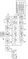
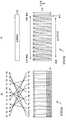
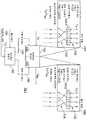
도 1은 예를 들어, DVB-T2 표준에 따라서 비디오 이미지 및 오디오 신호를 송신하는데 사용될 수 있는 OFDM 송신기의 예시적 블록도를 제공한다. 도 1에서, 프로그램 소스는 OFDM 송신기에 의해 송신될 데이터를 생성한다. 비디오 코더(2), 오디오 코더(4) 및 데이터 코더(6)는 프로그램 멀티플렉서(10)에 공급되는 송신될 비디오, 오디오 및 다른 데이터를 생성한다. 프로그램 멀티플렉서(10)의 출력은 비디오, 오디오 및 다른 데이터를 통신하는데 요구되는 다른 정보로 다중화된 스트림을 형성한다. 멀티플렉서(10)는 접속 채널(13) 상의 스트림을 제공한다. 상이한 브랜치 A, B 등으로 공급되는 다수의 멀티플렉스된 스트림이 존재할 수 있다. 명료성을 위해서, 브랜치 A만이 설명될 것이다.Figure 1 provides an exemplary block diagram of an OFDM transmitter that may be used, for example, to transmit video images and audio signals in accordance with the DVB-T2 standard. In Fig. 1, a program source generates data to be transmitted by an OFDM transmitter. The
도 1에 도시된 바와 같이, OFDM 송신기(11)는 멀티플렉서 적응 및 에너지 확산 블록(20)에서 스트림을 수신한다. 멀티플렉서 적응 및 에너지 확산 블록(20)은 데이터를 임의로 추출(randomise)하고, 스트림의 에러 정정 인코딩을 수행하는 순방향(forward) 에러 정정 인코더(21)로 적절한 데이터를 공급한다. 비트 인터리버(22)는, DVB-T2의 예에 있어서 LDPC 인코더 출력인 인코딩 데이터 비트를 인터리빙하도록 제공된다. 비트 인터리버(22)로부터의 출력은, 인코딩 데이터 비트를 전달하는데 사용될 배열 포인트로 비트 그룹을 매핑하는 비트 배열 매퍼(a bit into constellation mapper)(26)에 공급된다. 비트 배열 매퍼(26)로부터의 출력은 실수 성분 및 허수 성분을 나타내는 배열 포인트 레이블(label)이다. 배열 포인트 레이블은, 사용되는 변조 방식에 따라서 2개 이상의 비트로부터 형성되는 데이터 심볼을 나타낸다. 이들은 데이터 셀로 지칭될 것이다. 이 데이터 셀은, 다수의 LDPC 코드 워드로부터 나온 데이터 셀을 인터리빙하는 타임 인터리버(30)를 통과한다. 그 다음, 타임 인터리버(30)로부터의 데이터 셀은, 송신을 위한 변조 심볼로 데이터 셀을 매핑하는 변조 및 프레임 빌더(frame builder; 27)로 공급된다.As shown in FIG. 1, the
데이터 셀은 다른 채널(31)을 통해 프레임 빌더(32)에 의해 변조부(27)내에 수신되고, 데이터 셀은 도 1의 브랜치 B에 의해 생성된다. 그 다음, 프레임 빌더(32)는 OFDM 심볼에서 전달될 시퀀스로 다수의 데이터 셀을 형성하고, 여기에서 OFDM 심볼은 다수의 데이터 셀을 포함하고, 각각의 데이터 셀은 부반송파들 중 하나로 매핑된다. 부반송파의 수는 시스템의 동작 모드에 따를 것이고, 이 동작 모 드는 1k, 2k, 4k, 8k, 16k 또는 32k 중 하나를 포함할 수 있으며, 이들 각각은 예를 들어, 아래 표에 따라서 상이한 수의 부반송파를 제공한다.The data cell is received by the
DVB-T/H로부터 적응된 부반송파의 수 Number of subcarriers adapted from DVB-T / H
따라서, 일 예에서, 32k 모드에 대한 부반송파의 수는 24,192이다. DVB-T2 시스템에서, OFDM 심볼 당 부반송파의 수는 다른 예약된 반송파 및 파일럿의 수에 따라 변할 수 있다. 따라서, DVB-T2에서는, DVB-T와는 다르게, 데이터를 캐리하기 위한 부반송파의 수가 고정되지 않는다. 방송사업자는, 각각 OFDM 심볼 당 데이터에 대한 부반송파의 범위를 제공하는 1k, 2k, 4k, 8k, 16k, 32k로부터 동작 모드들 중 하나를 선택할 수 있고, 이들 모드 각각에 대해 이용가능한 최대 수는 각각 1024, 2048, 4096, 8192, 16384, 32768이다. DVB-T2에서, 물리층 프레임은 다수의 OFDM 심볼로 구성된다. 일반적으로, 프레임은 하나 이상의 프리앰블(preamble) 또는 P2 OFDM 심볼로 시작하고, 그 다음에는 다수의 패이로드(payload) 전달 OFDM 심볼이 후속한다. 물리층 프레임의 종료는 프레임 폐쇄 심볼로 표현된다. 각각의 동작 모드에 대해, 부반송파의 수는 각 심볼 형태에 대해 상이할 수 있다. 또한, 이는, 대역폭 확장이 선택되는지 여부, 톤 예약이 가능하게 되는지 여부 각각과, 어느 파일럿 부반송파 패턴이 선택되는지에 따라서 변할 수 있다. OFDM 심볼 당 부반송파의 특정 수에 대한 일반화는 어렵다. 그러나, 각 모드에 대한 주파수 인 터리버는, 그 부반송파의 수가 소정의 모드에 대한 부반송파의 최대 유효 수보다 작거나 같은 임의의 심볼을 인터리빙할 수 있다. 예를 들어, 1k 모드에서, 인터리버는 1024 이하의 부반송파의 수로 심볼에 대해 동작할 수 있고, 16k 모드에 대해서는, 16384 이하의 부반송파의 수로 동작할 수 있다.Thus, in one example, the number of subcarriers for the 32k mode is 24,192. In a DVB-T2 system, the number of subcarriers per OFDM symbol may vary depending on the number of other reserved carriers and pilots. Therefore, in DVB-T2, unlike DVB-T, the number of subcarriers for carrying data is not fixed. The broadcaster may select one of the operating modes from 1k, 2k, 4k, 8k, 16k, and 32k, each providing a range of subcarriers for data per OFDM symbol, and the maximum number available for each of these modes is 1024, 2048, 4096, 8192, 16384, and 32768, respectively. In DVB-T2, the physical layer frame is composed of a plurality of OFDM symbols. In general, a frame begins with one or more preamble or P2 OFDM symbols followed by a number of payload-carrying OFDM symbols. The end of the physical layer frame is represented by a frame closing symbol. For each mode of operation, the number of subcarriers may be different for each symbol type. It may also vary depending on whether bandwidth extension is selected, whether tone reservation is enabled, and which pilot subcarrier pattern is selected. It is difficult to generalize the specific number of subcarriers per OFDM symbol. However, the frequency inverter for each mode may interleave any symbol whose number of subcarriers is less than or equal to the maximum effective number of subcarriers for a given mode. For example, in the 1k mode, the interleaver may operate on symbols with a number of subcarriers equal to or less than 1024, and for a 16k mode with a number of subcarriers equal to or less than 16384.
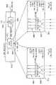
그 다음, 각각의 OFDM 심볼에서 전달될 데이터 셀의 시퀀스는 심볼 인터리버(33)로 보내진다. 다음으로 OFDM 심볼이, 파일럿 및 임베디드 신호 형성기(36)로부터 공급된 파일럿 및 동기화 신호를 도입하는 OFDM 심볼 빌더 블록(37)에 의해 생성된다. 그 다음, OFDM 변조기(38)는 OFDM 심볼을 시간 도메인에서 형성하고, 이 OFDM 심볼은, 심볼들 간의 가드(guard) 간격을 생성하기 위한 가드 삽입 프로세서(40)로 공급된 다음, 디지털 아날로그 변환기(42)로 공급되고, 마지막으로 안테나(46)로부터 OFDM 송신기에 의한 최종 방송을 위해 RF 전단(44) 내의 RF 증폭기로 공급된다.The sequence of data cells to be transmitted in each OFDM symbol is then sent to the
본 발명의 실시예는, 심볼 인터리버와 함께, LDPC 인코더로 인코딩되는 비트를 인터리빙하는 비트 인터리버를 포함하는 OFDM 통신 시스템을 제공하고, 심볼 인터리버는, 하나 이상의 인터리빙되고 인코딩된 비트를 나타내는 심볼을 OFDM 심볼의 부반송파 신호로 인터리빙한다. 예시적 실시예에 따른 비트 인터리버 및 심볼 인터리버는 모두 아래 단락들에서 설명되고, LDPC 인코딩으로 설명되는 비트 인터리버를 먼저 설명한다.An embodiment of the present invention provides an OFDM communication system including a bit interleaver for interleaving bits encoded with an LDPC encoder together with a symbol interleaver, wherein the symbol interleaver comprises a symbol representing one or more interleaved and encoded bits as an OFDM symbol Interleaving with the subcarrier signal of The bit interleaver and the symbol interleaver according to the exemplary embodiment are all described in the following paragraphs and first describe the bit interleaver described in LDPC encoding.
LDPC 인코딩을 위한 비트 인터리버Bit Interleaver for LDPC Encoding
LDPC 에러 정정 코드LDPC error correction code
LDPC 코드는 높은 에러 정정 성능을 가지며, 유럽(예를 들어, DVB-S.2:ETSI EN 302 307 V1.1.2(2006-06) 참조)에서 사용이 시작된 DVB-S.2와 같은 위성 디지털 방송을 포함하는 통신 방식에서 최근에 사용되기 시작하였다. 차세대 지상 디지털 방송에 LDPC 코드를 적용하는 것에 대해서도 논의되고 있다.The LDPC codes have high error correction performance and are used in satellite digital broadcasts such as DVB-S.2, which has begun to be used in Europe (for example, DVB-S.2:
최근의 연구는, 터보 코드와 유사하게, 코드 길이가 증가함에 따라 LDPC 코드의 성능이 섀넌 한계(shannon limit)에 접근한다는 것을 보여준다. LDPC 코드는 최소 거리가 코드 길이에 비례한다는 특성을 갖기 때문에, LDPC 코드는, 블록 에러 확률 특성이 우수하고, 터보 코드 등의 디코딩 특성과 관련하여 관찰되는 현상인 에러 플로어(error floor)가 거의 발생하지 않는다는 장점을 갖는다.Recent research shows that the performance of LDPC codes approaches the shannon limit as code length increases, similar to turbo codes. Since the LDPC code has a characteristic that the minimum distance is proportional to the code length, the LDPC code has an error floor that is excellent in block error probability characteristics and observed with respect to decoding characteristics such as turbo codes .
이제, 이러한 LDPC 코드에 대해 상세하게 살펴볼 것이다. LDPC 코드는 선형 코드이다. LDPC 코드가 반드시 2진수일 필요는 없지만, 아래에서는 2진 LDPC 코드를 참조하여 설명할 것이다.Now, this LDPC code will be described in detail. The LDPC code is a linear code. The LDPC code does not have to be a binary number, but will be described below with reference to a binary LDPC code.
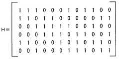
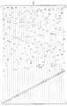
LDPC 코드의 가장 중요한 특성은, 각각의 LDPC 코드를 정의하는 패리티 검사 행렬이, 소자 "1"의 수가 매우 작은, 즉, 그 소자가 거의 "0"인 희소 행렬(sparse matrix)이라는 것이다.The most important characteristic of an LDPC code is that a parity check matrix defining each LDPC code is a sparse matrix in which the number of elements "1" is very small, i.e., the element is almost "0 ".
도 2는 LDPC 코드의 예시적 패리티 검사 행렬 H를 도시한다.Figure 2 shows an exemplary parity check matrix H of LDPC codes.
도 2의 패리티 검사 행렬 H의 각 열은 3의 가중치(weight)(즉, 3개의 "1" 소자)를 가지며, 각 행은 6의 가중치(즉, 6개의 "1"의 소자)를 갖는다.Each column of the parity check matrix H of FIG. 2 has a weight of 3 (i.e., three "1" elements) and each row has a weight of six (i.e., six elements of "1 ").
LDPC 코드에 기초한 인코딩(즉, LDPC 인코딩)은, 예를 들어, 패리티 검사 행렬 H에 기초하여 생성 행렬 G를 계산하고, 정보 비트로 생성 행렬 G를 승산하여 코 드워드(LDPC 코드)를 생성함으로써 수행된다.The encoding based on the LDPC code (i.e., LDPC encoding) is performed by, for example, calculating the generation matrix G based on the parity check matrix H and multiplying the generation matrix G with the information bits to generate code words (LDPC codes) do.
구체적으로, LDPC 인코더는 먼저 패리티 검사 행렬 H의 전치 행렬 HT로 방정식 GHT=0을 만족하는 생성 행렬 G를 계산한다. 여기에서, 생성 행렬 G가 K×N 행렬이면, 인코더는 생성 행렬 G를 K 비트의 정보 비트 시퀀스(벡터 u)로 승산하여 N 비트의 코드워드 c(=uG)를 생성한다. 인코더에 의해 생성된 코드워드(LDPC 코드)는 통신 경로를 통해서 수신측에서 수신된다.Specifically, the LDPC encoder first computes a generator matrix G that satisfies the equation GHT = 0 from the transpose matrix HT of the parity check matrix H. Here, if the generator matrix G is a KxN matrix, the encoder multiplies the generator matrix G by a K bit information bit sequence (vector u) to generate an N-bit code word c (= uG). The codeword (LDPC code) generated by the encoder is received at the receiving side via the communication path.
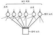
LDPC 코드는 Gallager에 의해 제안된 메시지 전달 알고리즘 및 제안된 "확률적 디코딩 알고리즘"에 의해 디코딩될 수 있다. 메시지 전달 알고리즘은 변수 노드(메시지 노드로도 지칭됨) 및 검사 노드를 포함하는 태너 그래프(Tanner graph) 상의 신뢰 확산(belief propagation)를 사용한다. 후속하는 설명에서, 변수 노드 및 검사 노드는 각각 간략하게 적절히 "노드"로서 지칭될 것이다.LDPC codes can be decoded by the proposed message-transfer algorithm proposed by Gallager and the proposed "probabilistic decoding algorithm ". The message forwarding algorithm uses belief propagation on a Tanner graph that includes variable nodes (also referred to as message nodes) and check nodes. In the following description, the variable node and the check node will each be referred to briefly as "node" as appropriate.
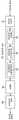
도 3은 LDPC 코드를 디코딩하는 절차를 도시한다.FIG. 3 shows a procedure for decoding an LDPC code.
이후에, 수신측에서 수신된 LDPC 코드(코드워드)의 i번째 코드 비트가 "0"의 값을 갖는 확률을 로그 가능성 비율(LLR; log likelihood ratio)로서 나타내는 실제 값(real value)이 적절하게 수신된 값 u01로서 지칭된다. 또한, 검사 노드로부터의 메시지 출력은 uj로서 지칭되고, 변수 노드로부터의 메시지 출력은 vi로서 지칭된다.Thereafter, a real value indicating a probability that the i-th code bit of the LDPC code (codeword) received at the receiving side has a value of "0 " as a log likelihood ratio (LLR) And is referred to as the received value u01 . The message output from the check node is also referred to as uj , and the message output from the variable node is referred to as vi .
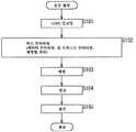
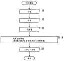
LDPC 코드는 아래와 같은 방식으로 디코딩된다. 우선, 도 3에 도시된 바와 같이, 단계 S11에서, LDPC 코드가 수신되고, 메시지(검사 노드 메시지) uj는 "0"으로 초기화되고, 상호적 처리의 카운터로서 정수값을 갖는 변수 k는 "0"으로 초기화된다. 그 다음, 절차는 단계 S12로 진행한다. 단계 S12에서, 수학식 1로 표현되는 계산(변수 노드 계산)이 LDPC 코드를 수신하여 얻어지는 수신된 값 u0i에 기초해서 수행되어, 메시지(변수 노드 메시지) vi가 얻어진 다음, 수학식 2로 표현되는 계산(검사 노드 계산)이 메시지 vi에 기초해서 수행되어, 메시지 uj가 얻어진다.The LDPC code is decoded in the following manner. 3, an LDPC code is received, a message (check node message) uj is initialized to "0 ", and a variable k having an integer value as a counter of reciprocal processing is set to" 0 ". Then, the procedure goes to step S12. In step S12, the calculation (variable node calculation) expressed by


수학식 1 및 수학식 2의 dv 및 dc는 패리티 검사 행렬 H의 수직 방향(열) 및 수평 방향(행)에서 1의 각각의 수(the respective numbers of 1s)를 나타내는 임의의 선택가능 파라미터이다. 예를 들어, (3,6) 코드의 경우 dv=3이고 dc=6이다.Dv and dc in equations (1) and (2) represent arbitrary selectable parameters (1) representing the respective numbers of 1s in the vertical direction (column) and the horizontal direction to be. For example, for the (3,6) code, dv = 3 and dc = 6.
수학식 1의 변수 노드 계산 및 수학식 2의 검사 노드 계산에서의 계산에 대한 각각의 범위는 1 내지 dv-1 및 1 내지 dc-1이고, 이는, 메시지를 출력하는 에지(즉, 변수 노드 및 검사 노드를 서로 접속하는 라인)로부터 수신된 메시지가 수학 식 1 및 2의 각 계산으로부터 제외되기 때문이다. 실제로, 수학식 2의 검사 노드 계산은, 수학식 4로 나타낸 바와 같이, 2개의 입력 v1 및 v2에 대해 하나의 출력으로서 정의되는 수학식 3으로 나타낸 함수 R(v1,v2)의 이전에 생성된 표를 재귀적으로 사용해서 수행된다.The respective ranges for the variable node computation of


단계 S12에서, 변수 k는 "1"씩 증가되고, 절차는 단계 S13으로 진행한다. 단계 S13에서, 변수 k가 선정된 디코딩의 반복 횟수 C보다 큰 지 여부가 결정된다. 단계 S13에서 변수 k가 C보다 크지 않다고 결정되면, 절차는 단계 S12로 되돌아가서 동일한 처리를 반복한다.In step S12, the variable k is incremented by "1 ", and the procedure goes to step S13. In step S13, it is determined whether or not the variable k is larger than the number of repetition times C of the selected decoding. If it is determined in step S13 that the variable k is not larger than C, the procedure returns to step S12 to repeat the same processing.
단계 S13에서 변수 k가 C보다 크다고 결정되면, 절차는 단계 S14로 진행하여, 수학식 5로 나타낸 계산을 수행하여 최종 디코딩 결과로서 메시지 vi를 획득하고 출력한다. 그 다음 LDPC 코드 디코딩 절차가 종료된다.If it is determined in step S13 that the variable k is larger than C, the procedure goes to step S14 to perform the calculation shown in

여기에서, 수학식 1의 변수 노드와 다르게, 수학식 5의 계산은 변수 노드에 접속된 모든 에지로부터의 메시지 uj를 사용해서 수행된다.Here, unlike the variable node of Equation (1), the calculation of Equation (5) is performed using the message uj from all edges connected to the variable node.
도 4는 1/2의 코드 레이트(code rate) 및 12의 코드 길이를 갖는 (3,6) LDPC 코드의 예시적 패리티 검사 행렬 H를 도시한다.4 shows an exemplary parity check matrix H of a (3, 6) LDPC code having a code rate of 1/2 and a code length of 12.
도 2의 패리티 검사 행렬 H로서, 도 4의 패리티 검사 행렬 H는 3의 열 가중치와 6의 행 가중치를 갖는다.As the parity check matrix H of FIG. 2, the parity check matrix H of FIG. 4 has a column weight of 3 and a row weight of 6.
도 5는 도 4의 패리티 검사 행렬 H의 태너 그래프를 도시한다.FIG. 5 shows a tanner graph of the parity check matrix H of FIG.
도 5에서, "+"는 검사 노드를 나타내고, "="는 변수 노드를 나타낸다. 검사 노드 및 변수 노드는 패리티 검사 행렬 H의 행 및 열에 각각 대응한다. 검사 노드 및 변수 노드의 쌍을 연결하는 각 연결 라인은 패리티 검사 행렬 H의 소자 "1"에 대응하는 에지이다.In Fig. 5, "+" represents a check node, and "=" represents a variable node. The check node and the variable node correspond to the rows and columns of the parity check matrix H, respectively. Each connection line connecting a pair of a check node and a variable node is an edge corresponding to element "1" of the parity check matrix H.
구체적으로, 패리티 검사 행렬의 j번째 행 소자 및 i번째 열 소자가 "1"이면, i번째 변수 노드 "=" (상부로부터 카운팅) 및 j번째 검사 노드 "+" (상부로부터 카운팅)는 도 5의 에지를 통해 접속된다. 에지는, 변수 노드에 대응하는 코드 비트가 검사 노드에 대응하는 제한을 갖는다는 것을 나타낸다.Specifically, when the j-th row element and the i-th column element of the parity check matrix are "1", the i-th variable node "=" (counting from the upper portion) and the jth check node "+" Lt; / RTI > The edge indicates that the code bit corresponding to the variable node has a restriction corresponding to the check node.
LDPC 코드 디코딩 알고리즘인 섬 프로덕트(sum product) 알고리즘은 변수 노드 계산 및 검사 노드 계산을 반복적으로 수행한다.The sum product algorithm, which is an LDPC code decoding algorithm, performs variable node computation and check node computation repeatedly.
도 6은 변수 노드에서 수행되는 변수 노드 계산을 도시한다.Figure 6 shows the variable node computation performed at a variable node.
계산용 에지에 대응하는 메시지 vi는, 변수 노드에 접속된 잔여 에지로부터의 메시지 u1및 u2 및 수신된 값 u0i을 사용해서 수학식 1의 변수 노드 계산에 따라 구해진다. 다른 에지에 대응하는 메시지는 동일한 방식으로 구해진다.The message vi corresponding to the computational edge is obtained according to the variable node computation of
도 7은 검사 노드에서 수행되는 검사 노드 계산을 도시한다.Figure 7 shows the check node calculation performed at the check node.
검사 노드 계산을 위한 상기 수학식 2는, a×b=exp{ln(|a|)+ln(|b|)}×sign(a)×sign(b)(여기에서, x≥0일 때 sign(x)는 1이고 x<0일 때 sign(x)는 -1임)의 관계식를 사용해서 수학식 6으로 재기록될 수 있다.The above formula (2) for the check node calculation is expressed by the following equation: a x b = exp ln (| a |) + ln (| b |)} sign (x) is 1 and sign (x) is -1 when x < 0).

또한, x≥0일 때 함수 φ(x)=ln(tanh(x/2))가 정의되면, 방정식 φ-1(x)=2tanh-1(e-x)가 만족되고, 이에 따라 수학식 6이 수학식 7로 재정리될 수 있다.Further, when x≥0 function φ (x) = ln (tanh (x / 2)) is defined, when the equationφ -1 (x) = 2tanh -1 (e -x) is satisfied, whereby the

검사 노드에서, 수학식 2의 검사 노드 계산은 수학식 7에 따라 수행된다.At the check node, the check node calculation of equation (2) is performed according to equation (7).
즉, 검사 노드에서, 계산용 에지에 대응하는 메시지 uj는, 도 7에 도시된 바와 같이 검사 노드에 접속된 잔여 에지로부터의 메시지 v1, v2, v3, v4, 및 v5를 사 용해서 수학식 7의 검사 노드 계산에 따라 구해진다. 다른 에지에 대응하는 메시지는 동일한 방식으로 구해진다.That is, at the check node, the message uj corresponding to the computational edge is the sum of the messages v1 , v2 , v3 , v4 , and v5 from the remaining edge connected to the check node, And is calculated according to the check node calculation in Equation (7). Messages corresponding to other edges are obtained in the same way.
수학식 7의 함수 φ(x)는, x>0일 때 φ(x)=ln((ex+1)/(ex-1)) 및 φ(x)=φ-1(x)와 같이 표현될 수도 있다. 함수 φ(x) 및 φ-1(x)이 하드웨어에 내장되는 경우, 이들은 동일한 룩업 테이블(LUT)을 사용해서 내장될 수 있다.(X) = ln ((ex +1) / (ex -1)) and φ (x) = φ-1 (x) when x> It can also be expressed as. If the functions φ (x) and φ-1 (x) are embedded in the hardware, they can be embedded using the same lookup table (LUT).
LDPC 코드가 AWGN 통신 경로에서 매우 우수한 성능을 나타내는 것으로 공지되었지만, 최근에, 종래의 컨볼루션 코드 또는 연접 리드 솔로몬(RS)-컨볼루션 코드에 비해, LDPC 코드가 다른 통신 경로에서 높은 에러 정정 성능을 갖는다는 것도 공지되었다.Although LDPC codes are known to exhibit very good performance in the AWGN communication path, it has recently been shown that compared to conventional convolutional codes or concatenated Reed Solomon (RS) -convolutional codes, LDPC codes have high error correction performance It is also known to have.
즉, AWGN 통신 경로에서의 우수한 성능을 갖는 코드가 선택되면, 선택된 코드는 일반적으로 다른 통신 경로에서도 다른 코드들에 비해 뛰어난 우수한 성능을 나타낸다.That is, if a code with superior performance in the AWGN communication path is selected, the selected code generally exhibits superior performance over other codes even on other communication paths.
예를 들어, LDPC 코드가 지상 디지털 방송에 적용되면서, DVB-S.2 사양에 정의된 LDPC 코드 및 DVB-T 사양에 정의된 변조 방식이 결합되고, LDPC 코드의 코드 비트를 인터리빙하는 비트 인터리버가 LDPC 인코더와 변조기 간에 제공되어, AWGN 통신 경로의 LDPC 코드의 성능을 향상시키는 것이 제안되었다.For example, when an LDPC code is applied to terrestrial digital broadcasting, a modulation scheme defined by the LDPC code defined in the DVB-S.2 specification and the DVB-T specification is combined, and a bit interleaver interleaving the code bits of the LDPC code It has been proposed to provide between the LDPC encoder and the modulator to improve the performance of the LDPC code of the AWGN communication path.
그러나, 소거 또는 버스트 에러는 지상파로 가정된 통신 경로에서 발생할 수 있다. 예를 들어, 직교 주파수 분할 다중(OFDM) 시스템에서, D/U(Desired to Undesired Ratio)가 0dB가 되어 바람직한 파워로서의 주경로 파워가 바람직하지 않 은 파워로서의 에코 파워와 동일한 다중 경로 환경에서, 주경로 외의 다른 경로인 에코의 지연으로 인해 특정 심볼이 소거될(즉, 전원이 0으로 떨어질) 수 있다.However, erasure or burst errors may occur in a communication path assumed to be terrestrial. For example, in an orthogonal frequency division multiplexing (OFDM) system, in a multipath environment where the desired to undesired ratio (D / U) becomes 0 dB and the main path power as a desirable power is equal to the echo power as undesirable power, A certain symbol may be erased (i.e., the power supply may drop to zero) due to the delay of the echo, which is a path other than the symbol.
D/U가 0dB이면, 특정 시간에서의 모든 OFDM 심볼은 또한, 도플러 주파수가 적용되고 지연이 "0"인 에코가 부가된 통신 경로인 플러터(flutter)의 도플러 주파수로 인해 소거될(즉, 전원이 0으로 떨어질) 것이다.If D / U is 0 dB, then all OFDM symbols at a particular time will also be erased due to the Doppler frequency of the flutter, which is the communication path to which the Doppler frequency is applied and the delay is "0 & Will fall to zero).
또한, 안테나로부터 수신기로의 와이어에서의 바람직하지 않은 조건 또는 불안정한 파워로 인해 버스트 에러가 발생할 수 있다.In addition, a burst error may occur due to undesirable conditions or unstable power in the wire from the antenna to the receiver.
관련 기술에서, AWGN 통신 경로에서 우수한 성능을 갖는 에러 정정 코드가 또한, 버스트 에러 또는 소거가 상술한 바와 같이 발생하는 통신 경로에서 빈번하게 사용된다.In the related art, error correction codes with superior performance in the AWGN communication path are also frequently used in communication paths where burst errors or erasures occur as described above.
반면에, LDPC 코드가 디코딩되면, 패리티 검사 행렬 H의 열뿐만 아니라 LDPC 코드의 코드 비트에 대응하는 변수 노드가, 도 6에 도시된 바와 같은 LDPC 코드의 코드 비트(수신된 값 u0i)의 부가와 관련된 수학식 1에 따라 계산된다. 따라서, 획득된 메시지의 정확도는, 변수 노드 계산에서 사용되는 코드 비트에서 에러가 발생하면 감소된다.On the other hand, when the LDPC code is decoded, not only the column of the parity check matrix H but also the variable node corresponding to the code bit of the LDPC code is added to the code bit (received value u0i ) of the LDPC code as shown in Fig. 1 < / RTI > Thus, the accuracy of the obtained message is reduced when an error occurs in the code bits used in the variable node computation.
또한, LDPC 코드가 디코딩되면, 검사 노드에 접속된 변수 노드에서 획득된 메시지를 사용해서 수학식 7에 따라 검사 노드가 계산된다. 따라서, 디코딩 성능은, 소거를 포함하는 에러가 다수의 검사 노드 각각에 접속된 복수의 변수 노드(에 대응하는 LDPC 코드의 복수의 코드 비트)에서 동시에 발생하면, 저하된다.Further, when the LDPC code is decoded, the check node is calculated according to Equation (7) using the message obtained at the variable node connected to the check node. Therefore, the decoding performance is degraded when an error including erasure occurs simultaneously in a plurality of variable nodes (a plurality of code bits of the LDPC code corresponding to each of the plurality of check nodes) connected to each of the plurality of check nodes.
보다 구체적으로, 예를 들어, 검사 노드에 접속된 2개 이상의 변수 노드가 동시에 소거되면, 검사 노드는, "1"의 확률과 동일한 "0"의 확률을 갖는 메시지를 검사 노드에 접속된 모든 변수 노드로 반환한다. 이 경우, "0" 및 "1"의 확률이 동이한 메시지를 반환하는 검사 노드는, 변수 노드 계산 및 검사 노드 계산의 세트인 일 디코딩 처리에 도움을 주지 않는다. 이는, 요구되는 디코딩 처리의 수를 증가시키고, 이에 따라 디코딩 성능을 저하시키며, LDPC 코드 디코딩을 수행하는 수신기의 파워 소비를 증가시킨다.More specifically, for example, when two or more variable nodes connected to a check node are simultaneously deleted, the check node sends a message having a probability of "0 " the same as the probability of & Returns to the node. In this case, a check node that returns a message having a probability of "0" and "1" does not help the one-decoding process, which is a set of variable node calculation and check node calculation. This increases the number of required decoding processes, thereby degrading the decoding performance and increasing the power consumption of the receiver performing LDPC code decoding.
따라서, AWGN 통신 경로의 성능을 유지하면서 버스트 에러 또는 소거에 대한 저항성을 증가시키는 방법을 제공할 필요가 있다.Therefore, there is a need to provide a way to increase the resistance to burst error or erasure while maintaining the performance of the AWGN communication path.
여기에서는, LDPC 코드의 코드 비트를 인터리빙하는 비트 인터리버가 LDPC 인코더와 변조기 간에 제공되어 상술한 바와 같이 AWGN 통신 경로에서의 LDPC 코드의 성능을 향상시키고, 비트 인터리버가, 검사 노드에 접속된 복수의 변수 노드(에 대응하는 LDPC 코드의 복수의 코드 비트)에서 에러가 동시에 발생할 확률을 낮추도록 인터리빙을 수행할 수 있도록 설계되면, 디코딩 성능을 향상시킬 수 있다.Here, a bit interleaver interleaving the code bits of the LDPC code is provided between the LDPC encoder and the modulator to improve the performance of the LDPC code in the AWGN communication path as described above, and the bit interleaver is provided with a plurality of variables It is possible to improve the decoding performance if it is designed to perform interleaving so as to lower the probability of simultaneous occurrence of errors in a node (a plurality of code bits of the LDPC code corresponding thereto).
본 발명은 상술한 환경의 관점에서 이루어진 것이며, 버스트 에러 또는 소거와 같은 LDPC 코드의 코드 비트에서의 에러에 대한 저항성을 증가시킬 수 있는 데이터 처리 장치 및 방법을 제공한다.The present invention has been made in view of the above environment and provides a data processing apparatus and method that can increase the resistance to errors in code bits of LDPC codes such as burst errors or erasures.
본 발명의 일 실시예에 따라서 데이터를 인터리빙하는 데이터 처리 장치는, LDPC 코드의 패리티 비트에 대응하는 패리티 행렬을 포함하는 패리티 검사 행렬에 따라서 LDPC 인코딩을 수행하여 획득되는 LDPC 코드에서 패리티 인터리빙을 수행하 는 패리티 인터리버 - 여기에서 패리티 행렬은 단계적 구조를 가짐 - 를 포함하여, LDPC 코드의 패리티 비트가 상이한 패리티 비트 위치들로 인터리빙된다.According to an embodiment of the present invention, a data processing apparatus for interleaving data performs parity interleaving in an LDPC code obtained by performing LDPC encoding according to a parity check matrix including a parity matrix corresponding to parity bits of an LDPC code The parity bits of the LDPC code are interleaved with different parity bit positions, including the parity interleaver, where the parity matrix has a step-wise structure.
본 발명의 일 실시예에 따라서 데이터를 인터리빙하는 데이터 처리 장치의 데이터 처리 방법은, 데이터 처리 장치가, LDPC 코드의 패리티 비트에 대응하는 패리티 행렬을 포함하는 패리티 검사 행렬에 따라서 LDPC 인코딩을 수행하여 획득되는 LDPC 코드에서 패리티 인터리빙을 수행하도록 하는 단계 - 여기에서 패리티 행렬은 단계적 구조를 가짐 - 를 포함하여, LDPC 코드의 패리티 비트가 상이한 패리티 비트 위치로 인터리빙된다.According to an embodiment of the present invention, a data processing method of a data processing apparatus for interleaving data is characterized in that the data processing apparatus performs LDPC encoding according to a parity check matrix including a parity matrix corresponding to parity bits of an LDPC code, Wherein the parity bits of the LDPC code are interleaved with different parity bit positions, including performing a parity interleaving in the LDPC code, wherein the parity matrix has a step structure.
즉, 본 발명의 실시예에 따라서, 패리티 인터리빙은, LDPC 코드의 패리티 비트에 대응하는 단계적 구조의 패리티 행렬을 포함하는 패리티 검사 행렬에 따라서 LDPC 인코딩을 수행하여 획득되는 LDPC 코드에서 수행되어, LDPC 코드의 패리티 비트가 상이한 패리티 비트 위치들로 인터리빙된다.That is, according to an embodiment of the present invention, parity interleaving is performed in an LDPC code obtained by performing LDPC encoding according to a parity check matrix including a parity matrix of a stepwise structure corresponding to parity bits of an LDPC code, Are interleaved with different parity bit positions.
데이터 처리 장치는 단독 장치일 수도 있고, 장치에 포함된 내부 블록일 수도 있다.The data processing apparatus may be a stand-alone apparatus or an internal block included in the apparatus.
예시적 비트 인터리버의 상세한 설명Detailed Description of Illustrative Bit Interleaver
도 8은 도 1에 도시된 송신기의 부분들을 보다 상세하게 나타내고, 비트 인터리버의 동작을 도시한다. 이제 LDPC 인코더(21)에 대해서 구체적으로 설명될 것이다. LDPC 인코더(21)는 패리티 검사 행렬에 따라 타겟 데이터에 대응하는 정보 비트를 포함하는 타겟 데이터를 LDPC 인코딩 데이터 비트로 인코딩하고, LDPC 코드의 패리티 비트에 대응하는 패리티 행렬은 단계적 구조를 갖는다.Figure 8 shows the parts of the transmitter shown in Figure 1 in greater detail and illustrates the operation of a bit interleaver. The
구체적으로, LDPC 인코더(21)는 예를 들어, DVB-S.2 사양에 따라서 정의된 LDPC 코드로 타겟 데이터를 인코딩하여, 그 LDPC 코드를 출력한다.Specifically, the
DVB-S.2 사양에 따라서 정의된 LDPC 코드는 IRA(Irregular Repeat Accumulate) 코드이고, LDPC 코드의 패리티 검사 행렬의 패리티 행렬은 단계적 구조를 갖는다. 패리티 행렬 및 그 단계적 구조의 상세가 후술될 것이다. IRA 코드의 일례가 2000년 9월, 터보 코드 및 관련 주제에 관한 2차 국제 심포지엄 회보의 H.Jin, A. Khandekar, 및 R.J. McEliece의 "Irregular Repeat-Accumulate Codes"에 기술되어 있다.The LDPC code defined in accordance with the DVB-S.2 specification is IRA (Irregular Repeat Accumulate) code, and the parity matrix of the parity check matrix of the LDPC code has a step structure. Details of the parity matrix and its staged structure will be described later. One example of an IRA code is H.Jin, A. Khandekar, and R.J. of the Second International Symposium on Turbo Codes and Related Topics, September 2000. It is described in McEliece's "Irregular Repeat-Accumulate Codes".
LDPC 인코더(21)로부터의 LDPC 코드 출력은 비트 인터리버(22)에 제공된다.The LDPC code output from the
비트 인터리버(22)는 데이터를 인터리빙하는 데이터 처리 장치이고, 패리티 인터리버(23), 열 트위스트 인터리버(24), 및 디멀티플렉서(25)를 포함한다.The bit interleaver 22 is a data processing apparatus that interleaves data and includes a
패리티 인터리버(23)는 LDPC 인코더(21)로부터의 LDPC 코드에서 패리티 인터리빙을 수행하여 LDPC 코드의 패리티 비트를 상이한 패리티 비트 위치로 인터리빙하고, 패리티 인터리빙된 LDPC 코드를 열 트위스트 인터리버(24)에 제공한다.The
열 트위스트 인터리버(24)는 패리티 인터리버(23)로부터의 LDPC 코드에서 열 트위스트 인터리빙을 수행한 다음, 열 트위스트 인터리빙된 LDPC 코드를 디멀티플렉서(25)에 제공한다.The thermal twisted
따라서, LDPC 코드는, LDPC 코드의 2개 이상의 코드 비트가 후술되는 매핑부(26)를 통해서 하나의 직교 변조된 심볼로 매핑된 후에, 송신된다.Thus, the LDPC code is transmitted after two or more code bits of the LDPC code are mapped to one orthogonally modulated symbol through a
열 트위스트 인터리버(24)는 패리티 인터리버(23)로부터 수신된 LDPC 코드의 코드 비트에서 치환(예를 들어, 후술될 열 트위스트 인터리빙) 처리를 수행하여, LDPC 인코더(21)에 의해 사용되는 패리티 검사 행렬의 임의의 행에서 "1"에 대응하는 LDPC 코드의 복수의 코드 비트가 하나의 심볼로 매핑되지 않게 한다.The thermal twisted
디멀티플렉서(25)는 열 트위스트 인터리버(24)로부터 수신된 LDPC 코드에 재정렬(reordering) 처리를 수행하여, 하나의 심볼로 매핑될 LDPC 코드의 2개 이상의 코드 비트의 위치가 재정렬되어, AWGN에 대한 저항성이 증가된 LDPC 코드를 얻은 다음, 매핑부(26)에 획득된 LDPC 코드를 제공한다.The
매핑부(26)는 디멀티플렉서(25)로부터의 LDPC 코드의 2개 이상의 코드 비트를 각 신호 포인트로 매핑하고, 이 신호 포인트는 직교 변조기(27)가 직교 변조(다중-값 변조)를 수행하는데 사용하는 변조 방식에 따라서 결정된다.The
보다 구체적으로, 매핑부(26)는 디멀티플렉서(25)로부터의 LDPC 코드를, IQ 면(IQ 배열)의 변조 방식에 따라 결정되는 신호 포인트에 의해 표현되는 심볼(심볼 값)로 변환하고, 이 IQ 면은, I 축은 반송파와 동일한 위상의 I 성분을 나타내고, Q 축은 반송파에 직교하는 Q 성분을 나타내는 것으로 정의된다.More specifically, the
도 1의 OFDM 송신기가 직교 변조를 수행하는데 사용하는 변조 방식은 DVB-T 사양에 정의된 변조 방식을 포함하고, 예로서 직교 위상 편이 변조(QPSK; Quadrature Phase Shift Keying), 16직교 진폭 변조(QAM; Quadrature Amplitude Modulation), 64QAM, 256QAM, 1024QAM, 4096QAM을 포함한다. 직교 변조기(27)가 직교 변조를 수행하는데 사용하는 변조 방식 중 하나는, 예를 들어, 도 1의 송신기를 동작시키는 오퍼레이터에 의한 동작을 통해 사전 설정된다. 직교 변조기(27)가 직교 변조를 수행하는데 사용하는 다른 변조 방식의 예는 4 펄스 진폭 변조(4PAM; 4 Pulse Amplitude Modulation)를 포함한다.The modulation schemes used by the OFDM transmitter of FIG. 1 to perform orthogonal modulation include the modulation schemes defined in the DVB-T specification, such as Quadrature Phase Shift Keying (QPSK), 16 Quadrature Amplitude Modulation (QAM) ; Quadrature Amplitude Modulation), 64QAM, 256QAM, 1024QAM, 4096QAM. One of the modulation schemes that
매핑부(26)에서 얻어지는 심볼은, 상이한 LDPC 코드 워드를 상이한 OFDM 심볼로 인터리빙하는 타임 인터리버에 제공된다. 타임 인터리버(30)의 출력은 도 1의 프레임 빌더에 공급된다. 도 1에 도시된 송신기의 나머지 부분은 매핑부(26)로부터 수신된 OFDM 심볼의 부반송파 신호의 직교 변조를 수행하여 변조 신호를 생성한 다음, 그 변조 신호를 송신한다.The symbols obtained in the
도 9는, 도 8의 LDPC 인코더(21)가 LDPC 인코딩에 사용하는 패리티 검사 행렬 H를 도시한다.FIG. 9 shows a parity check matrix H used by the
패리티 검사 행렬 H는 저밀도 생성 행렬(LDGM; Low-Density Generation Matrix) 구조를 가지며, 좌측 성분으로서 정보 행렬 HA를 우측 성분으로서 패리티 행렬 HT를 포함하는 방정식 "H=[HA|HT]"로 표현될 수 있고, 여기에서 정보 행렬 HA는 LDPC 코드의 코드 비트들 중 정보 비트에 대응하고, 패리티 행렬 HT는 패리티 비트에 대응한다.The parity check matrix H has a low-density generation matrix (LDGM) structure. The parity check matrix H has a matrix H = [HA | HT ] containing a parity matrix HT with the information matrix HA as a left- Where the information matrix HA corresponds to the information bits in the code bits of the LDPC code and the parity matrix HT corresponds to the parity bits.
여기에서, 하나의 LDPC 코드(하나의 코드워드)의 코드 비트들 중 정보 비트의 수 및 패리티 비트의 수는 정보 길이 K 및 패리티 길이 M으로 정의되고, 코드 비트의 수는 코드 길이 N(=K+M)으로 정의된다.Here, the number of information bits and the number of parity bits in the code bits of one LDPC code (one code word) are defined as an information length K and a parity length M, and the number of code bits is defined as a code length N (= K + M). ≪ / RTI >
코드 길이 N의 LDPC 코드의 정보 길이 K 및 패리티 길이 M은 코드 레이트에 기초해서 결정된다. 따라서, 패리티 검사 행렬 H는 M×N 행렬이다. 또한, 정보 행렬 HA는 M×K 행렬이고, 패리티 행렬 HT는 M×M 행렬이다.The information length K and the parity length M of the LDPC code of code length N are determined based on the code rate. Thus, the parity check matrix H is an M x N matrix. Also, the information matrix HA is an M x K matrix, and the parity matrix HT is an M x M matrix.
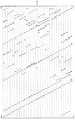
도 10은 DVB-S.2 사양에 정의된 LDPC 코드의 패리티 검사 행렬 H의 패리티 행렬 HT를 도시한다.10 shows the parity matrix HT of the parity check matrix H of the LDPC code defined in the DVB-S.2 specification.
DVB-S.2 사양에 정의된 LDPC 코드의 패리티 검사 행렬 H의 패리티 행렬 HT는 단계적 구조를 가져서, 패리티 행렬 HT의 "1"의 소자가 도 10에 도시된 바와 같이 단계적으로 배열된다. 패리티 검사 행렬 H의 제1 행은 1의 가중치를 갖고, 나머지 행은 2의 가중치를 갖는다.The parity matrix HT of the parity check matrix H of the LDPC code defined in the DVB-S.2 specification has a step structure, and the elements of "1" in the parity matrix HT are arranged stepwise as shown in FIG. The first row of the parity check matrix H has a weight of 1 and the remaining rows have a weight of 2.
단계적 구조의 패리티 행렬 HT를 갖는 패리티 검사 행렬 H의 LDPC 코드는 패리티 검사 행렬 H를 사용해서 용이하게 생성될 수 있다.The LDPC code of the parity check matrix H having the stepwise parity matrix HT can be easily generated using the parity check matrix H. [
보다 구체적으로, 행 벡터 c는 LDPC 코드(코드워드)를 나타내고, CT는 행 벡터를 전치함으로써 얻어지는 열 벡터를 나타내는 것으로 한다. 또한, 행 벡터 A는 LDPC 코드인 행 벡터 c의 정보 비트 부분을 나타내고, 행 벡터 T는 그 패리티 비트 부분을 나타내는 것으로 한다.More specifically, the row vector c represents an LDPC code (code word), and CT represents a column vector obtained by transposing a row vector. The row vector A represents the information bit portion of the row vector c which is the LDPC code, and the row vector T represents the parity bit portion thereof.
이 경우에, 행 벡터 c는, 좌측 성분으로서 행 벡터 A를 가지며 우측 성분으로서 행 벡터 T를 갖는 방정식 "c=[A|T]"로 표현될 수 있고, 여기에서 행 벡터 A는 정보 비트에 대응하고, 행 벡터 T는 패리티 비트에 대응한다.In this case, the row vector c can be represented by the equation "c = [A | T] ", which has the row vector A as the left component and the row vector T as the right component, And the row vector T corresponds to the parity bit.
패리티 검사 행렬 H, 및 LDPC 코드에 대응하는 행 벡터 c=[A|T]는 방정식 "HcT=0"을 만족해야 한다. 따라서, 행 벡터 c=[A|T]에 포함된 패리티 비트에 대응 하는 행 벡터 T의 각 소자의 값은, 패리티 검사 행렬 H=[HA|HT]의 패리티 행렬 HT가 도 10에 도시된 바와 같이 단계적 구조를 갖는다면, 제1 행의 소자에서 시작하는 순서로, 방정식 "HcT=0"의 열 벡터 HcT의 각 행의 소자를 0으로 설정함으로써 순차적으로 얻어질 수 있다.The parity check matrix H and the row vector c = [A | T] corresponding to the LDPC code must satisfy the equation "HcT = 0 ". Therefore, the value of each element of the row vector T corresponding to the parity bit included in the row vector c = [A | T] is set so that the parity matrix HT of the parity check matrix H = [HA | HT ] Can be sequentially obtained by setting the elements of each row of the column vector HcT of the equation "HcT = 0 " to 0 in order starting from the elements of the first row if they have a stepped structure as shown.
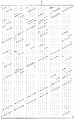
도 12A 및 12B는 DVB-S.2 사양에 정의된 열 가중치 및 LDPC 코드의 패리티 검사 행렬 H를 도시한다.12A and 12B show the parity check matrix H of the LDW code and the column weights defined in the DVB-S.2 specification.
즉, 도 111A는 DVB-S.2 사양에 정의된 LDPC 코드의 패리티 검사 행렬 H를 도시한다.That is, FIG. 111A shows the parity check matrix H of the LDPC code defined in the DVB-S.2 specification.
먼저, 패리티 검사 행렬 H의 KX번째 열은 X의 열 가중치를 갖고, 다음의 K3 열은 3의 열 가중치를 갖고, 다음의 M-1 열은 2의 열 가중치를 갖고, 마지막 열은 1의 열 가중치를 갖는다.First, the KX-th column of the parity check matrix H has a column weight of X, the next K3 column has a column weight of 3, the next M-1 column has a column weight of 2, Weight.
여기에서, 열 수의 합 "KX+K3+M-1+1"은 코드 길이 N과 같다.Here, the sum of the numbers of columns "KX + K3 + M-1 + 1"
DVB-S.2 사양에서, 열 수 KX, K3, 및 M(패리티 길이) 및 열 가중치 X는 도 111B에 도시된 바와 같이 정의된다.In the DVB-S.2 specification, the column numbers KX, K3, and M (parity length) and the column weight X are defined as shown in FIG. 111B.
즉, 도 111B는 DVB-S.2 사양에 정의된 LDPC 코드의 각 코드 레이트에 대한 열 수 KX, K3 및 M과 열 가중치 X를 도시한다.That is, FIG. 111B shows the column numbers KX, K3, and M and the column weights X for each code rate of the LDPC code defined in the DVB-S.2 specification.
각각 64800 비트 및 16200 비트의 N 코드 길이를 갖는 2개의 LDPC 코드가 DVB-S.2 사양에 정의된다.Two LDPC codes with N code lengths of 64800 bits and 16200 bits, respectively, are defined in the DVB-S.2 specification.
또한, 도 111B에 도시된 바와 같이, 11개의 공칭 코드 레이트 1/4, 1/3, 2/5, 1/2, 3/5, 2/3, 3/4, 4/5, 5/6, 8/9, 및 9/10이 코드 길이 N이 64800 비트인 LDPC 코드에 대해 정의되고, 10개의 공칭 코드 레이트 1/4, 1/3, 2/5, 1/2, 3/5, 2/3, 3/4, 4/5, 5/6, 및 8/9가 코드 길이 N이 16200 비트인 LDPC 코드에 대해 정의된다.Further, as shown in FIG. 111B, 11
LDPC 코드에 있어서, 패리티 검사 행렬 H의 코드 비트에 대응하는 열의 가중치가 증가함에 따라 코드 비트의 에러 레이트가 감소한다고 공지되어 있다.It is known that in the LDPC code, as the weight of the column corresponding to the code bit of the parity check matrix H increases, the error rate of the code bit decreases.
도 12A 및 12B에 도시된 DVB-S.2 사양에 정의된 패리티 검사 행렬 H의 경우, 열의 서수(ordinal number)가 감소함에 따라(즉, 열이 패리티 검사 행렬 H의 좌측단으로 근접함에 따라) 열의 가중치가 증가하고, 이에 따라, 코드 비트의 서수가 감소함에 따라 패리티 검사 행렬 H에 대응하는 LDPC 코드의 코드 비트가 에러에 대해(저항해서) 더욱 강해지고(즉, 제1 코드 비트가 가장 저항성이 크고), 코드 비트의 서수가 증가함에 따라 에러에 대해 더욱 약해지게 된다(즉, 마지막 코드 비트가 가장 약해진다).In the case of the parity check matrix H defined in the DVB-S.2 specification shown in FIGS. 12A and 12B, as the ordinal number of the columns decreases (i.e., as the columns approach the left end of the parity check matrix H) As the weight of the column increases, so that the code bit of the LDPC code corresponding to the parity check matrix H becomes stronger (resistive) against the error (i.e., the first code bit becomes the most resistant (I.e., the last code bit is weakest) as the ordinal number of the code bit increases.
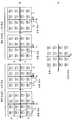
도 12A 및 도 12B는 16QAM이 도 8의 직교 변조기(27)에서 수행되는 경우의 IQ면의 16개의 심볼(에 대응하는 신호 포인트)의 구성을 도시한다.12A and 12B show the configuration of 16 symbols (corresponding to the signal points) of the IQ plane when 16QAM is performed in the
즉, 도 13A는 16QAM의 심볼을 도시한다.That is, FIG. 13A shows a symbol of 16QAM.
16QAM에서, 하나의 심볼은 4 비트를 나타내고, 16(=24)개의 심볼이 제공된다. 또한, 16개의 심볼은 I 및 Q 방향으로 4×4 심볼의 거듭제곱(square)으로 배열되고, IQ면의 원점을 중심으로 한다.In 16QAM, one symbol represents 4 bits and 16 (= 24 ) symbols are provided. In addition, the 16 symbols are arranged in a 4 x 4 symbol square in the I and Q directions, and centered on the origin of the IQ plane.
여기에서, y0, y1, y2, y3이 16QAM 중 하나의 심볼로 표현되는 4개의 비트를 나타낼 때, 실질적으로 최상위 비트(MSB)로부터 시작하여, 도 8의 매핑부(26)는 LDPC 코드의 4개의 코드 비트를, 변조 방식이 16QAM인 경우의 4 코드 비트에 대응하는 4개의 비트 y0 내지 y3의 심볼로 매핑한다.Here, when y0 , y1 , y2 , and y3 represent four bits represented by one symbol of 16QAM, starting from the most significant bit (MSB), the
도 13B는 16QAM 심볼로 표현되는 4개의 비트 y0 내지 y3의 비트 경계를 도시한다.13B shows bit boundaries of four bits y0 through y3 , which are represented by 16QAM symbols.
여기에서, 비트 yi(도 12A 및 12B에서 i=0, 1, 2, 3)의 비트 경계는 비트 yi가 "0"인 심볼과 비트 yi가 "1"인 심볼 간의 경계이다.Here, the bit yi of the bit boundaries (in FIGS. 12A and 12B i = 0, 1, 2 , 3) is the interface between the bit yi is "0" and the symbol bit yi is "1" symbol.
도 13B에 도시된 바와 같이, IQ면의 Q 축에 대응하는 경계는 16QAM 심볼로 표현되는 4개의 비트 y0 내지 y3의 제1 비트(즉, MSB) y0에 대한 유일한 비트 경계이고, IQ면의 I 축에 대응하는 경계는 제2 비트(즉, 제2 MSB) y1에 대한 유일한 비트 경계이다.13B, the boundary corresponding to the Q axis of the IQ plane is a unique bit boundary for the first bit (i.e., MSB) y0 of the four bits y0 to y3 represented by 16QAM symbols, and IQ The boundary corresponding to the I axis of the plane is the only bit boundary for the second bit (i.e., the second MSB) y1 .
또한, 4×4 심볼 중 심볼의 제1 및 제2 열 (좌측으로부터 카운팅) 간의 하나의 경계와, 제3 및 제4 열 간의 다른 하나의 경계, 즉, 2개의 경계들은 제3 비트 y2에 대한 비트 경계이다.In addition, 4 × 4 first of
또한, 4×4 심볼 중 제1 및 제2 행의 심볼들 (상부로부터 카운팅) 간의 하나의 경계와, 제3 및 제4 행 간의 다른 하나의 경계, 즉, 2개의 경계들은 제4 비트 y3 에 대한 비트 경계이다.In addition, 4 × 4 symbols of the first and second row of symbols (from counting above) one of the boundary and the other one of the interface between the third and fourth rows of the liver, that is, two boundaries are the fourth bit y3 Lt; / RTI >
심볼로 표현되는 각각의 비트 yi는, 비트 경계에서 먼 심볼의 수가 증가할수록 에러에 대해 더 강해지고, 비트 경계에서 가까운 심볼의 수가 증가할수록 에러에 대해 더 약해진다.Each bit yi represented by a symbol is stronger for errors as the number of symbols farther from the bit boundary increases and weaker for errors as the number of nearby symbols increases.
에러에 대해 저항성이 있는(강력한) 비트는 "강한 비트(strong bit)"로 불리고, 에러에 대해 약한(민감한) 비트는 "약한 비트(weak bit)"로 불리며, 도 12A 및 12B에 도시된 바와 같이, 제1 비트(즉, MSB) y0 및 제2 비트 y1는 강한 비트이고, 제3 비트 y2 및 제4 비트 y3는 약한 비트이다.A bit that is resistant to errors is called a "strong bit," and a weak (sensitive) bit for an error is called a "weak bit," as shown in FIGS. 12A and 12B Likewise, the first bit (i.e., MSB) y0 and the second bit y1 are strong bits, and the third bit y2 and fourth bit y3 are weak bits.
도 13 내지 도 15는, 64QAM이 도 8의 직교 변조기(27)에서 수행되는 경우의 IQ면의 64개의 심볼(에 대응하는 신호 포인트)의 구성을 도시한다.Figs. 13 to 15 show the configuration of 64 symbols (corresponding to the signal points) of the IQ plane when 64QAM is performed in the
64QAM에서, 하나의 심볼은 4개의 비트를 나타내고, 64(=26)개의 심볼이 제공된다. 또한, 64개의 심볼은 I 및 Q 방향으로 8×8 심볼의 스퀘어로 배열되고, IQ면의 원점을 중심으로 한다.In 64QAM, one symbol represents 4 bits and 64 (=26 ) symbols are provided. Further, 64 symbols are arranged in squares of 8x8 symbols in the I and Q directions, and centered on the origin of the IQ plane.
여기에서, y0, y1, y2, y3, y4, 및 y5가 64QAM 중 하나의 심볼로 표현되는 6개의 비트를 나타낼 때, 실질적으로 최상위 비트(MSB)로부터 시작하여, 도 8의 매핑부(26)는 LDPC 코드의 6개의 코드 비트를, 변조 방식이 64QAM인 경우의 6 코드 비트에 대응하는 6개의 비트 y0 내지 y5의 심볼로 매핑한다.Here, when y0 , y1 , y2 , y3 , y4 , and y5 represent six bits represented by one of 64QAM, starting from the most significant bit (MSB)
도 13은 64QAM 심볼로 표현되는 6개의 비트 y0 내지 y5중 제1 및 제2 비트 y0 및 y1의 비트 경계를 도시하고, 도 14는 제3 및 제4 비트 y2 및 y3의 비트 경계를 도시하고, 도 15는 제5 및 제6 비트 y4 및 y5의 비트 경계를 도시한다.13 shows the bit boundaries of the first and second bits y0 and y1 of the six bits y0 to y5 represented by 64QAM symbols, and FIG. 14 shows the bit boundary of the third and fourth bits y2 and y3 Bit boundary, and Fig. 15 shows the bit boundaries of the fifth and sixth bits y4 and y5 .
하나의 비트 경계가 도 14에 도시한 바와 같이 제1 및 제2 비트 y0 및 y1 각각에 대해 존재한다. 2개의 비트 경계가 도 14에 도시한 바와 같이 제3 및 제4 비트 y2 및 y3 각각에 대해 존재하고, 4개의 비트 경계가 도 15에 도시한 바와 같이 제5 및 제6 비트 y4 및 y5 각각에 대해 존재한다.One bit boundary exists for each of the first and second bits y0 and y1 as shown in FIG. Two bit boundaries exist for each of the third and fourth bits y2 and y3 as shown in FIG. 14, and four bit boundaries are present for the fifth and sixth bits y4 and y4 , y <5 >
따라서, 64QAM 심볼로 표현되는 6개의 비트 y0 내지 y5중 제1 및 제2 비트 y0 및 y1는 가장 강한 비트이고, 제3 및 제4 비트 y2 및 y3는 두번째로 강한 비트이고, 제5 및 제6 비트 y4 및 y5는 약한 비트이다.Thus, the first and second bits y0 and y1 of the six bits y0 to y5 represented by the 64QAM symbol are the strongest bits, and the third and fourth bits y2 and y3 are the second strongest bits , The fifth and sixth bits y4 and y5 are weak bits.
도 12, 도 13, 및 도 15로부터, 직교 변조된 심볼의 비트의 경우에, 더 중요한 비트는 강한 비트이고, 덜 중요한 비트는 약한 비트라는 것을 알 수 있다.12, 13 and 15, it can be seen that, in the case of bits of a quadrature modulated symbol, the more significant bit is the stronger bit and the less significant bit is the weaker bit.
도 8의 LDPC 인코더(21)로부터의 LDPC 코드 출력은 도 111을 참조해서 상술한 바와 같이 에러에 약한 코드 비트와 에러에 강한 코드 비트를 포함한다.The LDPC code output from the
직교 변조기(27)에 의해 직교 변조된 심볼의 비트는 도 12 내지 도 15를 참조해서 상술한 바와 같이 강한 비트와 약한 비트를 포함한다.The bits of the symbol orthogonally modulated by the
따라서, LDPC 코드의 에러에 약한 코드 비트가 직교 변조된 심볼의 약한 비트로 매핑되면, 에러에 대한 전체적인 저항성이 낮아진다.Thus, if the weak code bits to the error of the LDPC code are mapped to the weak bits of the orthogonally modulated symbol, the overall resistance to the error is low.
따라서, 본 발명은 LDPC 코드의 코드 비트를 인터리빙하여, LDPC 코드의 에 러에 약한 코드 비트가 직교 변조된 심볼의 강한 비트로 매핑되게 하는 인터리버를 제안한다.Therefore, the present invention proposes an interleaver which interleaves code bits of an LDPC code so that weak code bits are mapped to strong bits of a quadrature modulated symbol in the error of an LDPC code.
도 8의 디멀티플렉서(25)는 이 인터리버의 동작을 수행한다.The
도 16A 내지 16D는 도 8의 디멀티플렉서(25)의 동작을 도시한다.Figures 16A-16D illustrate the operation of the
구체적으로, 도 16A는 디멀티플렉서(25)의 예시적 기능적 구성을 도시한다.Specifically, FIG. 16A shows an exemplary functional configuration of the
디멀티플렉서(25)는 메모리(31) 및 재정렬부(32)를 포함한다. LDPC 코드는 메모리(31)에 제공된다. 메모리(31)는 행(수평) 방향으로 mb 비트를 저장하고 열(수직) 방향으로 N/mb 비트를 저장하기 위한 저장 용량을 갖는다. 메모리(31)에 제공되는 LDPC 코드의 코드 비트는 메모리(31)에 열 방향으로 기록되고, 메모리(31)로부터 행 방향으로 판독된 다음, 판독된 코드 비트가 재정렬부(32)에 제공된다.The
여기에서, "m"은 하나의 심볼에 매핑된 LDPC 코드의 코드 비트의 수를 나타내고, "b"는 "m"이 승산되어 "m"의 정수배(integral multiple)를 얻게 하는 특정 양의 정수(즉, 팩터)를 나타낸다. 또한, "N"(= 정보 길이 K + 패리티 길이 M)은 상술한 바와 같이 LDPC 코드의 코드 길이를 나타낸다.Here, "m" denotes the number of code bits of the LDPC code mapped to one symbol, "b" denotes a specific positive integer (" That is, a factor). Further, "N" (= information length K + parity length M) represents the code length of the LDPC code as described above.
도 16A는 변조 방식이 64QAM일 때의 디멀티플렉서(25)의 예시적 구성을 도시한다. 따라서, 하나의 심볼로 매핑되는 LDPC 코드의 코드 비트의 수 "m"은 6이다.16A shows an exemplary configuration of the
도 16A에서, 팩터 "b"는 1이고, 이에 따라 메모리(31)는 열 및 행 방향으로 N/(6×1)×(6×1) 비트의 저장 용량을 갖는다.16A, the factor "b" is 1, and thus the
아래에서, 행 방향으로 1 비트이고 열 방향으로 확장하는, 메모리(31)의 저 장 영역은 적절히 열로서 지칭된다. 도 16A의 예에서, 메모리(31)는 6(=6×1) 열을 포함한다.Below, the storage area of the
디멀티플렉서(25)는, 최좌측으로부터 시작하여 우측으로 순차적으로, 각 열의 상부로부터 하부로의 열 방향으로 메모리(31)에 LDPC 코드의 코드 비트를 기록한다.The
코드 비트가 최우측 열의 바닥부까지 완전히 기록되면, 코드 비트는, 6 비트(즉, mb 비트)의 단위로 메모리(31)의 모든 열의 제1 행으로부터 시작하여 순차적으로, 행 방향으로 메모리(31)로부터 판독되고, 판독된 코드 비트는 재정렬부(32)에 제공된다.When the code bits are completely written to the bottom of the rightmost column, the code bits are sequentially written in the memory 31 (in the row direction) starting from the first row of all the columns of the
재정렬부(32)는 메모리(31)로부터 수신된 6개의 코드 비트의 위치를 재정렬하고, 6개의 재정렬된 비트를, 하나의 64QAM 심볼을 나타내는 6 비트 y0, y1, y2, y3, y4, 및 y5로서 출력한다.Reordering unit 32 y3 a reordering the positions of the six code received bit, and six reordered bits from the
보다 구체적으로, 행 방향으로 메모리(31)로부터 판독된 6개의 코드 비트가 MSB로부터 순차적으로 시작하여 b0, b1, b2, b3, b4, 및 b5로 표현되면, 도 111을 참조해서 상술한 바와 같은 열 가중치 관계에 따라서, 비트 "b0"에 인접하며 이를 포함하는 코드 비트는 에러에 강한 코드 비트이고, 비트 "b5"에 인접하며 이를 포함하는 코드 비트는 에러에 약한 코드 비트이다.More specifically, if the six code bits read out from the
재정렬부(32)는 메모리(31)로부터 수신된 6개의 코드 비트 b0 내지 b5의 위 치를 재정렬하여, 메모리(31)로부터 6개의 코드 비트 b0 내지 b5 중 에러에 약한 코드 비트가 하나의 64QAM 심볼을 나타내는 6개의 비트 y0 내지 y5 중 강한 비트에 할당되게 한다.
다수의 회사들이 메모리(31)로부터 6개의 코드 비트 b0 내지 b5를 재정렬하고 이들을 하나의 64QAM 심볼을 나타내는 6개의 비트 y0 내지 y5로 각각 할당하는 여러 가지 방법을 제안해 왔다.A number of companies have proposed various ways of reordering the six code bits b0 to b5 from the
도 16B는 제1 재정렬 방법을 도시하고, 도 16C는 제2 재정렬 방법을 도시하고, 도 16D는 제3 재정렬 방법을 도시한다.FIG. 16B shows a first reordering method, FIG. 16C shows a second reordering method, and FIG. 16D shows a third reordering method.
도 16B 내지 16D에서, 비트 bi와 yj를 연결하는 라인은, 후술될 도 17A 및 17B와 유사하게, 코드 비트 bi가 심볼 비트 yj에 할당됨(즉, 코드 비트 bi의 위치가 심볼 비트 yj의 위치로 변함)을 나타낸다.In Figure 16B to 16D, becomes the bit bi and the line connecting the yj is, in analogy to FIGS. 17A and 17B will be described later, the code bit bi is assigned to the symbol bit yj (that is, the positions of the code bits bi To the position of the symbol bit yj ).
도 16B의 제1 재정렬 방법은 3개의 재정렬 형태 중 하나를 사용하는 것을 제안하고, 도 16C의 제2 재정렬 방법은 2개의 재정렬 형태 중 하나를 사용하는 것을 제안한다.The first reordering method of FIG. 16B suggests using one of the three reordering forms, and the second reordering method of FIG. 16C suggests using one of the two reordering forms.
도 16D의 제3 재정렬 방법은 6개의 재정렬 형태의 순차적 선택 및 사용을 제안한다.The third reordering method of FIG. 16D suggests sequential selection and use of six reordering forms.
도 17A 및 도 17B는 디멀티플렉서(25)의 예시적 구성, 및 변조 방법이 64QAM이고(따라서 도 16에서와 같이 하나의 심볼에 매핑된 LDPC 코드의 코드 비트의 수 "m"이 6임) 팩터 "b"가 2인 경우의 제4 재정렬 방법을 도시한다.17A and 17B show an exemplary configuration and demodulation method of the
팩터 "b"가 2일 때, 메모리(31)는 열 및 행 방향으로 N/(6×2)×(6×2) 비트의 저장 용량을 갖고, 12(=6×2)개의 열을 갖는다.When the factor "b" is 2, the
도 17A는, LDPC 코드의 코드 비트가 메모리(31)에 기록되는 순서를 도시한다.17A shows the order in which the code bits of the LDPC code are written into the
디멀티플렉서(25)는, 도 16A를 참조해서 상술한 바와 같이 최좌측 열로부터 시작하여 우측으로 순차적으로, 각 열의 상부로부터 하부로의 열 방향으로 메모리(31)에 LDPC 코드의 코드 비트를 기록한다.The
코드 비트가 최우측 열의 바닥부까지 완전히 기록되면, 코드 비트는, 12 비트(즉, mb 비트)의 단위로 메모리(31)의 모든 열의 제1 행으로부터 시작하여 순차적으로, 행 방향으로 메모리(31)로부터 판독되고, 판독된 코드 비트는 재정렬부(32)에 제공된다.When the code bits are completely written to the bottom of the rightmost column, the code bits are written in the memory 31 (i. E., Starting from the first row of all the columns of the
재정렬부(32)는 메모리(31)로부터 수신된 12개의 코드 비트의 위치를 재정렬하고, 12개의 재정렬된 비트를, 64QAM의 2개의 심볼(즉, b 심볼)을 나타내는 12 비트, 즉, 하나의 64QAM 심볼을 나타내는 6 비트 y0, y1, y2, y3, y4, 및 y5와 다른 심볼을 나타내는 6 비트 y0, y1, y2, y3, y4, 및 y5로서 출력한다.The
도 17B는 도 17A의 재정렬부(32)에 의해 수행되는 제4 재정렬 방법을 도시한다.FIG. 17B shows a fourth reordering method performed by the
AWGN 통신 경로에서의 에러 레이트를 최소화하는 최적의 재정렬 방법은 LDPC 코드 등의 코드 레이트에 좌우된다.The optimal reordering method that minimizes the error rate in the AWGN communication path depends on the code rate, such as LDPC codes.
이제 도 8의 패리티 인터리버(23)가 어떻게 패리티 인터리빙을 수행하는 지에 대해서 도 18 내지 20을 참조해서 설명될 것이다.Now, how the
도 18은 LDPC 코드의 패리티 검사 행렬의 태너 그래프(의 일부)를 도시한다.18 shows (part of) the tanner graph of the parity check matrix of the LDPC code.
소거와 같은 에러가 검사 노드(또는 이에 대응하는 2개 이상의 코드 비트)에 접속된 2개 이상의 변수 노드에서 동시에 발생하면, 검사 노드는, "1"의 확률과 동일한 "0"의 확률을 갖는 메시지를 도 18에 도시한 바와 같은 검사 노드에 접속된 모든 변수 노드로 반환한다. 따라서, 동일한 검사 노드에 접속된 다수의 변수 노드가 소거되면 디코딩 성능은 저하된다.If an error such as an erasure occurs simultaneously in two or more variable nodes connected to a check node (or two or more code bits corresponding thereto), then the check node will send a message with a probability of "0 & To all variable nodes connected to the check node as shown in Fig. Therefore, decoding performance deteriorates when a plurality of variable nodes connected to the same check node are erased.
도 8의 LDPC 인코더(21)에 의해 출력되는 DVB-S.2 사양에 정의된 LDPC 코드는 IRA 코드이고, 패리티 검사 행렬 H의 패리티 행렬 HT는 도 11에 도시된 바와 같은 단계적 구조를 갖는다.The LDPC code defined in the DVB-S.2 specification output by the
도 19A 및 19B는 단계적 구조를 갖는 패리티 행렬 HT 및 패리티 행렬 HT에 대응하는 태너 그래프를 도시한다.Figure 19A and 19B shows a Tanner graph corresponding to the parity matrix HT, and the parity matrix HT having a stepwise structure.
즉, 도 19A는 단계적 구조를 갖는 패리티 행렬 HT를 도시하고, 도 19B는 도 19A의 패리티 행렬 HT에 대응하는 태너 그래프를 도시한다.That is, FIG. 19A shows a parity matrix HT having a stepped structure, and FIG. 19B shows a tanner graph corresponding to the parity matrix HT of FIG. 19A.
패리티 행렬 HT가 단계적 구조를 가지면, 패리티 행렬 HT에서 "1"의 값을 갖는 소자를 포함하는 열에 대응하는, LDPC 코드의 인접하는 코드 비트(패리티 비트) 를 사용해서 메시지가 얻어지는 변수 노드는 패리티 행렬 HT의 태너 그래프의 동일한 검사 노드에 연결된다.If the parity matrix HT has a stepped structure, the variable node from which the message is obtained using the adjacent code bits (parity bits) of the LDPC code, corresponding to the column containing the element having the value of "1" in the parity matrix HT Is connected to the same check node of the tanner graph of the parity matrix HT.
따라서, 버스트 에러 또는 소거와 같은 에러가 인접하는 패리티 비트에서 동시에 발생하면, 에러가 있는 패리티 비트에 각각 대응하는 변수 노드(즉, 메시지가 패리티 비트를 사용해서 얻어지는 변수 노드)에 접속된 검사 노드가, "1"의 확률과 동일한 "0"의 확률을 갖는 메시지를 검사 노드에 접속된 모든 변수 노드로 반환하기 때문에, 디코딩 성능은 저하된다. 디코딩 성능은, 또한, 버스트로 인한 에러가 있는 비트의 수인 버스트 길이가 최대일 때, 저하된다.Therefore, if errors such as burst errors or erasures occur simultaneously in adjacent parity bits, a check node connected to a variable node (i.e., a variable node obtained by using a message with a parity bit) corresponding to each parity bit with an error , Decoding performance is degraded because a message having a probability of "0" equal to the probability of "1" is returned to all variable nodes connected to the check node. The decoding performance also deteriorates when the burst length, which is the number of bits with errors due to bursts, is the maximum.
다음으로, 도 8의 패리티 인터리버(23)는 LDPC 인코더(21)로부터의 LDPC 코드에서 패리티 인터리빙을 수행하여, 디코딩 성능의 저하를 막기 위해서 LDPC 코드의 패리티 비트를 상이한 패리티 비트 위치들로 인터리빙한다.Next, the
도 20은 도 8의 패리티 인터리버(23)가 LDPC 코드에 대한 패리티 인터리빙을 수행한 후에 LDPC 코드에 대응하는 패리티 검사 행렬 H의 패리티 행렬 HT를 도시한다.FIG. 20 shows the parity matrix HT of the parity check matrix H corresponding to the LDPC code after the
여기에서, LDPC 인코더(21)로부터 출력된 DVB-S.2 사양에 정의된 LDPC 코드에 대응하는 패리티 검사 행렬 H의 정보 행렬 HA는 순환적 구조를 갖는다.Here, the information matrix HA of the parity check matrix H corresponding to the LDPC code defined in the DVB-S.2 specification output from the
용어 "순환적 구조"는, 열이 순환적으로 시프트될 때, 다른 열에 매칭되는 구조를 지칭한다. 순환적 구조의 예는, 매 P 열의 각 행의 소자 "1"의 위치가, 패리티 길이 "M"을 나누어서 얻어지는 값 "q"에 비례하는 값에 의해 열 방향으로 순 환적으로 시프트되는 P 열의 제1 위치에 대응하는 구조를 포함한다. 다음으로, 순환적 구조의 열의 수 "P"는 적절히 순환적 구조를 갖는 열의 단위 수로서 지칭된다.The term "cyclic structure" refers to a structure that is matched to another column when the heat is cyclically shifted. An example of the cyclic structure is that the position of the element "1" in each row of every P column is shifted in the column direction by a value proportional to the value "q " obtained by dividing the parity length & 1 < / RTI > positions. Next, the number of columns "P" of the cyclic structure is properly referred to as the number of units of the column having a cyclic structure.
LDPC 인코더(21)로부터 출력된 DVB-S.2 사양에 정의된 LDPC 코드의 예는, 도 12를 참조해서 상술한 바와 같이 64800 비트 및 16200 비트의 각 코드 길이 N을 갖는 LDPC 코드의 2개의 형태를 포함한다.An example of the LDPC code defined in the DVB-S.2 specification output from the
이제, 64800 비트 및 16200 비트의 각 코드 길이 N을 갖는 LDPC 코드의 2개의 형태 중 64800 비트의 코드 길이 N을 갖는 LDPC 코드의 형태에 초점을 맞추어 설명될 것이다. 11개의 공칭 코드 레이트가, 도 12를 참조해서 상술한 바와 같이 그 코드 길이 N이 64800인 LDPC 코드에 대해 정의된다.Now, it will be described focusing on the form of LDPC code having a code length N of 64800 bits among the two types of LDPC codes having each code length N of 64800 bits and 16200 bits. Eleven nominal code rates are defined for LDPC codes whose code length N is 64800 as described above with reference to FIG.
11개의 공칭 코드 레이트 각각의 64800 비트의 코드 길이 N을 갖는 임의의 LDPC 코드에 대해서, 순환적 구조를 갖는 열의 단위수 P는 DVB-S.2 사양의, 패리티 길이 M의 제수들(1 및 M 제외) 중 하나인 "360"으로 정의된다.For any LDPC code having a code length N of 64800 bits of each of the 11 nominal code rates, the number of columns P with a cyclic structure is determined by dividing the
11개의 공칭 코드 레이트 각각의 64800 비트의 코드 길이 N을 갖는 LDPC 코드에 대해서, 패리티 길이 M은 코드 레이트에 따라 변하는 값 "q"를 사용해서 M=q×P=q×360에 따라 비-소수 값(non-prime value)으로 계산된다. 따라서, 순환적 구조를 갖는 열의 단위수 P와 유사하게, 값 "q"는 패리티 길이 M의 또 다른 제수(1 및 M 제외)이고, 순환적 구조를 갖는 열의 단위수 P에 의해 패리티 길이 M을 나눔으로써 계산된다(즉, 패리티 길이 M은 패리티 길이 M의 제수 "P" 및 "q"의 곱이다).For an LDPC code having a code length N of 64800 bits of each of the 11 nominal code rates, the parity length M is calculated by multiplying the non-prime number < RTI ID = 0.0 > And is calculated as a non-prime value. Thus, similar to the unit number P of columns having a cyclic structure, the value "q" is another divisor (excluding 1 and M) of the parity length M, and the parity length M (I.e., the parity length M is the product of the divisors "P" and "q" of the parity length M).
K가 정보 길이일 때, x는 0 이상이고 P 미만의 정수이고, y는 0 이상이고 q 미만의 정수이고, 패리티 인터리버(23)는 LDPC 인코더(21)로부터 수신된 LDPC 코드에 대해 패리티 인터리빙을 수행하여, LDPC 코드의 K+1번째 내지 K+M(=N)번째 코드 비트인 패리티 비트들 중 K + qx + y + 1 번째 코드 비트를 K + Py + x + 1 번째 코드 비트 위치로 인터리빙한다.When K is the information length, x is an integer of 0 or more and less than P, y is an integer of 0 or more and less than q, and the
이러한 패리티 인터리빙 방법에 따라서, 동일한 검사 노드에 접속된 변수 노드(에 대응하는 패리티 비트)는 순환적 구조를 갖는 열의 단위수 P(이 예에서는 360 비트)에 대응하는 거리에 있고, 이에 따라, 동일한 검사 노드에 접속된 복수의 변수 노드에서 에러가 동시에 발생되는 것이 방지된다. 이는 버스트 에러에 대한 저항성을 향상시킬 수 있다.According to this parity interleaving method, the variable nodes (corresponding parity bits) connected to the same check node are at a distance corresponding to the unit number P (360 bits in this example) of a column having a cyclic structure, It is prevented that errors occur simultaneously in a plurality of variable nodes connected to the check node. This can improve the resistance to burst errors.
패리티 인터리빙 동작이 수행되어 K + qx + y + 1 번째 코드 비트가 K + Py + x + 1 번째 코드 비트 위치로 인터리빙되게 되는 LDPC 코드는, 원래의 패리티 검사 행렬 H에 열 치환을 수행하여, 원래의 패리티 검사 행렬 H의 K + Py + x + 1 번째 열을 K + qx + y + 1 번째 열로 대체(구체적으로, 교환)함으로써 얻어지는 패리티 검사 행렬(이후에, 변환된 패리티 검사 행렬로서 지칭됨)의 LDPC 코드와 동일하다.The parity interleaving operation is performed so that the K + qx + y + 1 th code bit is interleaved with the K + Py + x + 1 th code bit position, performs column replacement on the original parity check matrix H, (Hereinafter referred to as the converted parity check matrix) obtained by replacing (specifically exchanging) the K + Py + x + 1 th column of the parity check matrix H of the parity check matrix H with the (K + qx + y + Lt; / RTI >
변환된 패리티 검사 행렬의 패리티 행렬은, 도 20에 도시된 바와 같이 열의 단위 수가 "P"(도 20에서는 "360")인 의사 순환적 구조를 갖는다.The parity matrix of the converted parity check matrix has a pseudo-cyclic structure in which the number of columns is "P" ("360" in FIG. 20) as shown in FIG.
여기에서, 용어 "의사 순환적 구조(pseudo-cyclic structure)"는, 패리티 행렬의 특정 부분을 제외한 패리티 행렬의 일 부분이 순환적 구조를 갖는 구조를 지 칭한다. DVB-S.2 사양에 정의된 LDPC 코드의 패리티 검사 행렬에 대해 패리티 인터리빙에 대응하는 열 치환을 수행함으로써 얻어지는 변환된 패리티 검사 행렬은 소자 "1"이 단 하나인 짧은 순환적 구조의 (후술하는 시프트된 행렬에 대응하는) 360×360 우측 코너부를 갖는다(즉, 360×360 우측 코너부는 순환적 구조에서 요구되는 "1" 이 아닌 "0"의 소자를 갖는다). 변환된 패리티 검사 행렬이 (완전한) 순환적 구조를 갖지 않기 때문에, "의사 순환적 구조"를 갖는 것으로 지칭된다.Here, the term "pseudo-cyclic structure" refers to a structure in which a part of a parity matrix except for a specific part of the parity matrix has a cyclic structure. The converted parity check matrix obtained by performing the column replacement corresponding to the parity interleaving on the parity check matrix of the LDPC code defined in the DVB-S.2 specification has a short cyclic structure (I.e., 360 x 360 right corner portion has a "0" element that is not "1 " required in a cyclic structure). Is referred to as having a "pseudo-cyclic structure" since the transformed parity check matrix does not have a (complete) recursive structure.
실제로, 도 20의 변환된 패리티 검사 행렬은, 패리티 인터리빙에 대응하는 열 치환에 더하여, 원래의 패리티 검사 행렬 H에 행 치환을 수행하여 얻어져서, 변환된 패리티 검사 행렬이 후술되는 성분 행렬을 포함하도록 한다.Actually, the transformed parity check matrix of FIG. 20 is obtained by performing row substitution on the original parity check matrix H in addition to column substitution corresponding to parity interleaving, so that the transformed parity check matrix includes a component matrix described later do.
이제, 도 8의 열 트위스트 인터리버(24)가 어떻게 치환 처리로서 열 트위스트 인터리빙을 수행하는지에 대해서 도 21 내지 도 24를 참조해서 설명할 것이다.Now, how the thermal twisted
도 8의 송신기(11)는, 주파수의 사용 효율을 향상시키기 위해서 상술한 바와 같이 LDPC 코드의 2개 이상의 코드 비트를 하나의 심볼로서 송신한다. 예를 들어, 2개의 코드 비트가 하나의 심볼로서 송신될 때 QPSK가 변조 방법으로서 사용되고, 4개의 코드 비트가 하나의 심볼로서 송신될 때 16QAM이 변조 방법으로서 사용된다.The
2개 이상의 코드 비트가 상술한 바와 같이 심볼로서 송신되는 경우에 일 심볼에서 소거 에러와 같은 에러가 발생하면, 심볼의 모든 코드 비트가 에러가 있게 된다(즉, 소거된다).If two or more code bits are transmitted as symbols as described above and an error such as an erasure error occurs in one symbol, then all code bits of the symbol will be erroneous (i.e. erased).
따라서, 디코딩 성능의 향상을 위해, 동일한 검사 노드에 접속된 변수 노드(에 대응하는 코드 비트)가 동시에 소거되는 확율을 낮추기 위해서, 하나의 심볼의 코드 비트에 대응하는 변수 노드가 동일한 검사 노드에 접속되는 것을 방지할 필요가 있다.Therefore, in order to improve the decoding performance, in order to lower the probability that the variable nodes (corresponding to the code bits) connected to the same check node are simultaneously erased, variable nodes corresponding to the code bits of one symbol are connected to the same check node .
한편, LDPC 인코더(21)로부터 출력된 DVB-S.2 사양에 정의된 LDPC 코드의 패리티 검사 행렬 H의 경우에, 패리티 검사 행렬 H의 정보 행렬 HA는 순환적 구조를 갖고, 패리티 행렬 HT는 상술한 바와 같이 단계적 구조를 갖는다. 패리티 인터리빙되는 LDPC 코드의 패리티 검사 행렬인 변환된 패리티 검사 행렬의 경우에, 패리티 행렬은 또한 도 20을 참조해서 상술한 바와 같이 순환적 구조(구체적으로, 의사 순환적 구조)를 갖는다.On the other hand, in the case of the parity check matrix H of the LDPC code defined in the DVB-S.2 specification outputted from the
도 21A 및 도 21B는 변환된 패리티 검사 행렬을 도시한다.Figures 21A and 21B show the transformed parity check matrix.
구체적으로, 도 21A는 64800 비트의 코드 길이 N 및 3/4의 코드 레이트(r)를 갖는 LDPC 코드의 패리티 검사 행렬 H의 변환된 패리티 검사 행렬을 도시한다.Specifically, FIG. 21A shows a transformed parity check matrix of a parity check matrix H of an LDPC code having a code length N of 64800 bits and a code rate r of 3/4.
도 21A에서, 변환된 패리티 검사 행렬에서 "1"의 값을 갖는 각 소자의 위치는 점 "."으로 도시된다.In Fig. 21A, the position of each element having a value of "1 " in the transformed parity check matrix is shown as a dot". &Quot;.
도 21B는 도 8의 디멀티플렉서(25)가 도 21A의 변환된 패리티 검사 행렬의 LDPC 코드, 즉, 패리티 인터리빙되는 LDPC 코드에서 수행하는 동작을 도시한다.FIG. 21B shows an operation performed by the
도 21B에서, 변조 방법으로서 16QAM을 사용하여, 패리티 인터리빙된 LDPC 코드의 코드 비트는, 디멀티플렉서(25)의 메모리(31)를 구성하는 4개의 열에 열 방향으로 기록된다.21B, the code bits of the parity-interleaved LDPC code are written in the column direction in the four columns constituting the
메모리(31)의 4개의 열에 열 방향으로 기록된 코드 비트는 하나의 심볼로서 4 비트의 단위로 행 방향으로 판독된다.The code bits recorded in the column direction in the four columns of the
이 경우에, 하나의 심볼의 4개의 코드 비트 B0, B1, B2, B3은 도 21A의 변환된 패리티 검사 행렬에서 임의의 행의 "1"에 대응하는 복수의 코드 비트를 포함할 수 있다. 이 경우, 4개의 코드 비트 B0, B1, B2, B3에 대응하는 변수 노드는 동일한 검사 노드에 접속된다.In this case, the four code bits B0 , B1 , B2 , and B3 of one symbol include a plurality of code bits corresponding to "1" of any row in the transformed parity check matrix of FIG. 21A . In this case, the variable nodes corresponding to the four code bits B0 , B1 , B2 , B3 are connected to the same check node.
따라서, 심볼의 4개의 코드 비트 B0, B1, B2, B3이 변환된 패리티 검사 행렬에서 임의의 행의 "1"에 대응하는 코드 비트를 포함하는 경우에 심볼에서 소거가 발생하면, 코드 비트 B0, B1, B2, B3에 각각 대응하는 변수 노드에 접속된 동일한 검사 노드에 대해 적절한 메시지를 얻는 것이 어렵고, 이에 따라 디코딩 성능이 저하된다.Therefore, when an erasure occurs in a symbol in the case where four code bits B0 , B1 , B2 , and B3 of the symbol include code bits corresponding to "1" of an arbitrary row in the converted parity check matrix, It is difficult to obtain an appropriate message for the same check node connected to the variable node corresponding to the code bits B0 , B1 , B2 , and B3 , respectively, thereby degrading the decoding performance.
3/4 이외의 코드 레이트가 이용되면, 동일한 검사 노드에 접속된 복수의 변수 노드에 대응하는 복수의 코드 비트가 하나의 16QAM 심볼을 구성할 수 있다.If a code rate other than 3/4 is used, a plurality of code bits corresponding to a plurality of variable nodes connected to the same check node can constitute one 16QAM symbol.
따라서, 열 트위스트 인터리버(24)는 패리티 인터리버(23)로부터의 패리티 인터리빙된 LDPC 코드에 열 트위스트 인터리빙을 수행하여, 패리티 인터리빙된 LDPC 코드의 코드 비트를 인터리빙함으로써, 변환된 패리티 검사 행렬에서 임의의 행의 "1"에 대응하는 복수의 코드 비트가 하나의 심볼로 매핑되지 않게 된다.Therefore, the thermal twisted
도 22는 열 트위스트 인터리빙이 어떻게 수행되는 지를 도시한다.22 illustrates how thermal twist interleaving is performed.
구체적으로, 도 22는 도 16 및 도 17에 도시된 디멀티플렉서(25)의 메모리(31)를 도시한다.Specifically, Fig. 22 shows the
메모리(31)는 행(수평) 방향으로 mb 비트를 저장하고 열(수직) 방향으로 N/mb 비트를 저장하기 위한 저장 용량을 갖고, 도 16을 참조해서 상술한 바와 같이 mb 열을 포함한다. 열 트위스트 인터리버(24)는, LDPC 코드의 코드 비트가 열 방향으로 메모리(31)에 기록되고 행 방향으로 메모리(31)로부터 판독될 때, 열에서 기록이 개시되는 메모리(31)의 각 열에서의 기록 개시 위치를 제어함으로써 열 트위스트 인터리빙을 수행한다.The
보다 구체적으로, 열 트위스트 인터리버(24)는, 코드 비트가 복수의 열 각각에 기록되기 시작하는 기록 개시 위치를 적절히 변경하여, 하나의 심볼을 구성하도록 행 방향으로 판독된 복수의 코드 비트가, 변환된 패리티 검사 행렬에서 임의의 행의 "1"에 대응하는 복수의 코드 비트를 포함하지 않게 된다. 즉, 열 트위스트 인터리버(24)는 LDPC 코드의 코드 비트를 치환하여, 패리티 검사 행렬에서 임의의 행의 "1"에 대응하는 복수의 코드 비트가 동일한 심볼로 결합되지 않게 한다.More specifically, the thermal twisted
도 22는, 16QAM이 변조 방법으로서 사용되고 도 16을 참조해서 설명된 팩터 "b"가 "1"인 경우의 메모리(31)의 예시적 구성을 도시한다. 따라서, 하나의 심볼로 매핑되는 LDPC 코드의 코드 비트의 수 "m"은 4이고, 메모리(31)는 4(=mb)개의 열을 포함한다.Fig. 22 shows an exemplary configuration of the
(도 16의 디멀티플렉서(25) 대신에) 도 22의 열 트위스트 인터리버(24)는, 최좌측 열로부터 시작하여 우측으로 순차적으로, 메모리(31)의 4개의 열 각각의 상부로부터 하부로의 열 방향으로 메모리(31)에 LDPC 코드의 코드 비트를 기록한다.(Instead of the
코드 비트가 최우측 열까지 완전히 기록되면, 열 트위스트 인터리버(24)는, 메모리(31)의 모든 열의 제1 행으로부터 시작하여, 행 방향으로 4개의 비트(mb 비트)의 단위로 코드 비트를 판독하고, 판독된 코드 비트를 열 트위스트 인터리빙된 LDPC 코드로서, 도 16 및 17에 도시된 디멀티플렉서(25)의 재정렬부(32)에 출력한다.When the code bits are completely written to the rightmost column, the column twisted
각 열의 제1(상부) 위치의 어드레스가 "0"으로 표현되고, 열 방향에 따른 각 위치의 어드레스가 순차적으로 증가하는 정수로 표현되면, 도 22의 열 트위스트 인터리버(24)는, 최좌측 열의 기록 개시 위치의 어드레스가 "0"이고, 2번째 열의 기록 개시 위치의 어드레스가 "2"이고, 3번째 열의 기록 개시 위치의 어드레스가 "4"이고, 4번째 열의 기록 개시 위치의 어드레스가 "7"이라고 결정한다.When the address of the first (upper) position of each column is represented by "0" and the address of each position along the column direction is expressed by an integer increasing sequentially, the
코드 비트가, 열의 하부 위치까지 "0" 이외의 어드레스에서 기록 개시 위치를 갖는 열에 기록된 후에, 열 트위스트 인터리버(24)는 어드레스 "0"에서의 열의 제1 위치로 돌아가서, 기록 개시 위치 직전의 위치까지 열에 코드 비트를 계속 기록한다. 그 다음 열 트위스트 인터리버(24)는 다음 우측 열에 기록을 수행한다.The
상술한 바와 같이 열 트위스트 인터리빙을 수행하는 것은, 동일한 검사 노드에 접속된 복수의 변수 노드에 대응하는 복수의 코드 비트가, DVB-S.2 사양에 정의된 바와 같은 64800의 코드 길이 N을 갖는 매 코드 레이트의 LDPC 코드에 대해 16QAM의 하나의 심볼에 할당되는 것(즉, 동일한 심볼로 결합되는 것)을 방지할 수 있다. 이는 소거가 발생하는 통신 경로에서의 디코딩 성능을 향상시킬 수 있다.Performing the twisted-twisted interleaving as described above means that a plurality of code bits corresponding to a plurality of variable nodes connected to the same check node are assigned to each of the code nodes having a code length N of 64800 as defined in the DVB-S.2 specification It is possible to prevent the code rate LDPC code from being allocated to one symbol of 16QAM (i.e., combined with the same symbol). This can improve the decoding performance in the communication path where erasure occurs.
도 23은 열 트위스트 인터리빙에 요구되는 메모리(31)의 열의 수, 및 DVB-S.2 사양에 정의된 바와 같은 64800의 코드 길이 N을 갖는 11개의 코드 레이트 각 각의 LDPC 코드에 대한 각각의 변조 방법과 관련된 기록 개시 위치의 어드레스를 도시한다.23 shows the number of columns of
도 16의 제1 내지 제3 재정렬 방법 중 하나가 도 8에 도시된 디멀티플렉서(25)의 재정렬 처리에서 이용되고, QPSK가 변조 방법으로서 이용되는 경우, 하나의 심볼의 비트의 수 "m"은 2이고, 팩터 "b"는 1이다.When one of the first through third reordering methods of FIG. 16 is used in the reordering processing of the
이 경우에, 메모리(31)는 행 방향으로 2×1(=mb) 비트를 저장하기 위한 2개의 열을 갖고, 도 23에 도시된 바와 같이 열 방향으로 64800/(2×1) 비트를 저장한다. 메모리(31)의 2개의 열 중 첫번째 열의 기록 개시 위치는 어드레스 "0"에 있고, 2번째 열의 기록 개시 위치는 어드레스 "2"에 있다.In this case, the
또한, 도 17의 제4 재정렬 방법이 도 8에 도시된 디멀티플렉서(25)의 재정렬 처리에서 이용되고, QPSK가 변조 방법으로서 이용되는 경우, 하나의 심볼의 비트의 수 "m"은 2이고, 팩터 "b"는 2이다.When the fourth reordering method of Fig. 17 is used in the reordering processing of the
이 경우에, 메모리(31)는 행 방향으로 2×2 비트를 저장하기 위한 4개의 열을 갖고, 도 23에 도시된 바와 같이 열 방향으로 64800/(2×2) 비트를 저장한다. 메모리(31)의 4개의 열 중 첫번째 열의 기록 개시 위치는 어드레스 "0"에 있고, 2번째 열의 기록 개시 위치는 어드레스 "2"에 있고, 3번째 열의 기록 개시 위치는 어드레스 "4"에 있고, 4번째 열의 기록 개시 위치는 어드레스 "7"에 있다.In this case, the
또한, 도 16의 제1 내지 제3 재정렬 방법 중 하나가 도 8에 도시된 디멀티플렉서(25)의 재정렬 처리에서 이용되고, 16QAM이 변조 방법으로서 이용되는 경우, 하나의 심볼의 비트의 수 "m"은 4이고, 팩터 "b"는 1이다.When one of the first to third reordering methods of FIG. 16 is used in the reordering process of the
이 경우에, 메모리(31)는 행 방향으로 4×1 비트를 저장하기 위한 4개의 열을 갖고, 도 23에 도시된 바와 같이 열 방향으로 64800/(4×1) 비트를 저장한다. 메모리(31)의 4개의 열 중 첫번째 열의 기록 개시 위치는 어드레스 "0"에 있고, 2번째 열의 기록 개시 위치는 어드레스 "2"에 있고, 3번째 열의 기록 개시 위치는 어드레스 "4"에 있고, 4번째 열의 기록 개시 위치는 어드레스 "7"에 있다.In this case, the
또한, 도 17의 제4 재정렬 방법이 도 8에 도시된 디멀티플렉서(25)의 재정렬 처리에서 이용되고, 16QAM이 변조 방법으로서 이용되는 경우, 하나의 심볼의 비트의 수 "m"은 4이고, 팩터 "b"는 2이다.When the fourth reordering method of Fig. 17 is used in the reordering processing of the
이 경우에, 메모리(31)는 행 방향으로 4×2 비트를 저장하기 위한 8개의 열을 갖고, 도 23에 도시된 바와 같이 열 방향으로 64800/(4×2) 비트를 저장한다. 메모리(31)의 8개의 열 중 첫번째 열의 기록 개시 위치는 어드레스 "0"에 있고, 2번째 열의 기록 개시 위치는 어드레스 "0"에 있고, 3번째 열의 기록 개시 위치는 어드레스 "2"에 있고, 4번째 열의 기록 개시 위치는 어드레스 "4"에 있고, 5번째 열의 기록 개시 위치는 어드레스 "4"에 있고, 6번째 열의 기록 개시 위치는 어드레스 "5"에 있고, 7번째 열의 기록 개시 위치는 어드레스 "7"에 있고, 8번째 열의 기록 개시 위치는 어드레스 "7"에 있다.In this case, the
또한, 도 16의 제1 내지 제3 재정렬 방법 중 하나가 도 8에 도시된 디멀티플렉서(25)의 재정렬 처리에서 이용되고, 64QAM이 변조 방법으로서 이용되는 경우, 하나의 심볼의 비트의 수 "m"은 6이고, 팩터 "b"는 1이다.When one of the first to third reordering methods in Fig. 16 is used in the reordering processing of the
이 경우에, 메모리(31)는 행 방향으로 6×1 비트를 저장하기 위한 6개의 열 을 갖고, 도 23에 도시된 바와 같이 열 방향으로 64800/(6×1) 비트를 저장한다. 메모리(31)의 6개의 열 중 첫번째 열의 기록 개시 위치는 어드레스 "0"에 있고, 2번째 열의 기록 개시 위치는 어드레스 "2"에 있고, 3번째 열의 기록 개시 위치는 어드레스 "5"에 있고, 4번째 열의 기록 개시 위치는 어드레스 "9"에 있고, 5번째 열의 기록 개시 위치는 어드레스 "10"에 있고, 6번째 열의 기록 개시 위치는 어드레스 "13"에 있다.In this case, the
또한, 도 17의 제4 재정렬 방법이 도 8에 도시된 디멀티플렉서(25)의 재정렬 처리에서 이용되고, 64QAM이 변조 방법으로서 이용되는 경우, 하나의 심볼의 비트의 수 "m"은 6이고, 팩터 "b"는 2이다.When the fourth reordering method of Fig. 17 is used in the reordering processing of the
이 경우에, 메모리(31)는 행 방향으로 6×2 비트를 저장하기 위한 12개의 열을 갖고, 도 23에 도시된 바와 같이 열 방향으로 64800/(6×2) 비트를 저장한다. 메모리(31)의 12개의 열 중 첫번째 열의 기록 개시 위치는 어드레스 "0"에 있고, 2번째 열의 기록 개시 위치는 어드레스 "0"에 있고, 3번째 열의 기록 개시 위치는 어드레스 "2"에 있고, 4번째 열의 기록 개시 위치는 어드레스 "2"에 있고, 5번째 열의 기록 개시 위치는 어드레스 "3"에 있고, 6번째 열의 기록 개시 위치는 어드레스 "4"에 있고, 7번째 열의 기록 개시 위치는 어드레스 "4"에 있고, 8번째 열의 기록 개시 위치는 어드레스 "5"에 있고, 9번째 열의 기록 개시 위치는 어드레스 "5"에 있고, 10번째 열의 기록 개시 위치는 어드레스 "7"에 있고, 11번째 열의 기록 개시 위치는 어드레스 "8"에 있고, 12번째 열의 기록 개시 위치는 어드레스 "9"에 있다.In this case, the
또한, 도 16의 제1 내지 제3 재정렬 방법 중 하나가 도 8에 도시된 디멀티플렉서(25)의 재정렬 처리에서 이용되고, 256QAM이 변조 방법으로서 이용되는 경우, 하나의 심볼의 비트의 수 "m"은 8이고, 팩터 "b"는 1이다.When one of the first to third reordering methods in Fig. 16 is used in the reordering processing of the
이 경우에, 메모리(31)는 행 방향으로 8×1 비트를 저장하기 위한 8개의 열을 갖고, 도 23에 도시된 바와 같이 열 방향으로 64800/(8×1) 비트를 저장한다. 메모리(31)의 8개의 열 중 첫번째 열의 기록 개시 위치는 어드레스 "0"에 있고, 2번째 열의 기록 개시 위치는 어드레스 "0"에 있고, 3번째 열의 기록 개시 위치는 어드레스 "2"에 있고, 4번째 열의 기록 개시 위치는 어드레스 "4"에 있고, 5번째 열의 기록 개시 위치는 어드레스 "4"에 있고, 6번째 열의 기록 개시 위치는 어드레스 "5"에 있고, 7번째 열의 기록 개시 위치는 어드레스 "7"에 있고, 8번째 열의 기록 개시 위치는 어드레스 "7"에 있다.In this case, the
또한, 도 17의 제4 재정렬 방법이 도 8에 도시된 디멀티플렉서(25)의 재정렬 처리에서 이용되고, 256QAM이 변조 방법으로서 이용되는 경우, 하나의 심볼의 비트의 수 "m"은 8이고, 팩터 "b"는 2이다.Also, when the fourth reordering method of Fig. 17 is used in the reordering processing of the
이 경우에, 메모리(31)는 행 방향으로 8×2 비트를 저장하기 위한 16개의 열을 갖고, 도 23에 도시된 바와 같이 열 방향으로 64800/(8×2) 비트를 저장한다. 메모리(31)의 16개의 열 중 첫번째 열의 기록 개시 위치는 어드레스 "0"에 있고, 2번째 열의 기록 개시 위치는 어드레스 "2"에 있고, 3번째 열의 기록 개시 위치는 어드레스 "2"에 있고, 4번째 열의 기록 개시 위치는 어드레스 "2"에 있고, 5번째 열의 기록 개시 위치는 어드레스 "2"에 있고, 6번째 열의 기록 개시 위치는 어드레 스 "3"에 있고, 7번째 열의 기록 개시 위치는 어드레스 "7"에 있고, 8번째 열의 기록 개시 위치는 어드레스 "15"에 있고, 9번째 열의 기록 개시 위치는 어드레스 "16"에 있고, 10번째 열의 기록 개시 위치는 어드레스 "20"에 있고, 11번째 열의 기록 개시 위치는 어드레스 "22"에 있고, 12번째 열의 기록 개시 위치는 어드레스 "22"에 있고, 13번째 열의 기록 개시 위치는 어드레스 "27"에 있고, 14번째 열의 기록 개시 위치는 어드레스 "27"에 있고, 15번째 열의 기록 개시 위치는 어드레스 "28"에 있고, 16번째 열의 기록 개시 위치는 어드레스 "32"에 있다.In this case, the
또한, 도 16의 제1 내지 제3 재정렬 방법 중 하나가 도 8에 도시된 디멀티플렉서(25)의 재정렬 처리에서 이용되고, 1024QAM이 변조 방법으로서 이용되는 경우, 하나의 심볼의 비트의 수 "m"은 10이고, 팩터 "b"는 1이다.When one of the first through third reordering methods of FIG. 16 is used in the reordering processing of the
이 경우에, 메모리(31)는 행 방향으로 10×1 비트를 저장하기 위한 10개의 열을 갖고, 도 23에 도시된 바와 같이 열 방향으로 64800/(10×1) 비트를 저장한다. 메모리(31)의 10개의 열 중 첫번째 열의 기록 개시 위치는 어드레스 "0"에 있고, 2번째 열의 기록 개시 위치는 어드레스 "3"에 있고, 3번째 열의 기록 개시 위치는 어드레스 "6"에 있고, 4번째 열의 기록 개시 위치는 어드레스 "8"에 있고, 5번째 열의 기록 개시 위치는 어드레스 "11"에 있고, 6번째 열의 기록 개시 위치는 어드레스 "13"에 있고, 7번째 열의 기록 개시 위치는 어드레스 "15"에 있고, 8번째 열의 기록 개시 위치는 어드레스 "17"에 있고, 9번째 열의 기록 개시 위치는 어드레스 "18"에 있고, 10번째 열의 기록 개시 위치는 어드레스 "20"에 있다.In this case, the
또한, 도 17의 제4 재정렬 방법이 도 8에 도시된 디멀티플렉서(25)의 재정렬 처리에서 이용되고, 1024QAM이 변조 방법으로서 이용되는 경우, 하나의 심볼의 비트의 수 "m"은 10이고, 팩터 "b"는 2이다.Further, when the fourth reordering method of Fig. 17 is used in the reordering processing of the
이 경우에, 메모리(31)는 행 방향으로 10×2 비트를 저장하기 위한 20개의 열을 갖고, 도 23에 도시된 바와 같이 열 방향으로 64800/(10×2) 비트를 저장한다. 메모리(31)의 20개의 열 중 첫번째 열의 기록 개시 위치는 어드레스 "0"에 있고, 2번째 열의 기록 개시 위치는 어드레스 "1"에 있고, 3번째 열의 기록 개시 위치는 어드레스 "3"에 있고, 4번째 열의 기록 개시 위치는 어드레스 "4"에 있고, 5번째 열의 기록 개시 위치는 어드레스 "5"에 있고, 6번째 열의 기록 개시 위치는 어드레스 "6"에 있고, 7번째 열의 기록 개시 위치는 어드레스 "6"에 있고, 8번째 열의 기록 개시 위치는 어드레스 "9"에 있고, 9번째 열의 기록 개시 위치는 어드레스 "13"에 있고, 10번째 열의 기록 개시 위치는 어드레스 "14"에 있고, 11번째 열의 기록 개시 위치는 어드레스 "14"에 있고, 12번째 열의 기록 개시 위치는 어드레스 "16"에 있고, 13번째 열의 기록 개시 위치는 어드레스 "21"에 있고, 14번째 열의 기록 개시 위치는 어드레스 "21"에 있고, 15번째 열의 기록 개시 위치는 어드레스 "23"에 있고, 16번째 열의 기록 개시 위치는 어드레스 "25"에 있고, 17번째 열의 기록 개시 위치는 어드레스 "25"에 있고, 18번째 열의 기록 개시 위치는 어드레스 "26"에 있고, 19번째 열의 기록 개시 위치는 어드레스 "28"에 있고, 20번째 열의 기록 개시 위치는 어드레스 "30"에 있다.In this case, the
또한, 도 16의 제1 내지 제3 재정렬 방법 중 하나가 도 8에 도시된 디멀티플렉서(25)의 재정렬 처리에서 이용되고, 4096QAM이 변조 방법으로서 이용되는 경우, 하나의 심볼의 비트의 수 "m"은 12이고, 팩터 "b"는 1이다.When one of the first through third reordering methods of FIG. 16 is used in the reordering processing of the
이 경우에, 메모리(31)는 행 방향으로 12×1 비트를 저장하기 위한 12개의 열을 갖고, 도 23에 도시된 바와 같이 열 방향으로 64800/(12×1) 비트를 저장한다. 메모리(31)의 12개의 열 중 첫번째 열의 기록 개시 위치는 어드레스 "0"에 있고, 2번째 열의 기록 개시 위치는 어드레스 "0"에 있고, 3번째 열의 기록 개시 위치는 어드레스 "2"에 있고, 4번째 열의 기록 개시 위치는 어드레스 "2"에 있고, 5번째 열의 기록 개시 위치는 어드레스 "3"에 있고, 6번째 열의 기록 개시 위치는 어드레스 "4"에 있고, 7번째 열의 기록 개시 위치는 어드레스 "4"에 있고, 8번째 열의 기록 개시 위치는 어드레스 "5"에 있고, 9번째 열의 기록 개시 위치는 어드레스 "5"에 있고, 10번째 열의 기록 개시 위치는 어드레스 "7"에 있고, 11번째 열의 기록 개시 위치는 어드레스 "8"에 있고, 12번째 열의 기록 개시 위치는 어드레스 "9"에 있다.In this case, the
또한, 도 17의 제4 재정렬 방법이 도 8에 도시된 디멀티플렉서(25)의 재정렬 처리에서 이용되고, 4096QAM이 변조 방법으로서 이용되는 경우, 하나의 심볼의 비트의 수 "m"은 12이고, 팩터 "b"는 2이다.When the fourth reordering method of FIG. 17 is used in the reordering processing of the
이 경우에, 메모리(31)는 행 방향으로 12×2 비트를 저장하기 위한 24개의 열을 갖고, 도 23에 도시된 바와 같이 열 방향으로 64800/(12×2) 비트를 저장한다. 메모리(31)의 24개의 열 중 첫번째 열의 기록 개시 위치는 어드레스 "0"에 있고, 2번째 열의 기록 개시 위치는 어드레스 "5"에 있고, 3번째 열의 기록 개시 위치는 어드레스 "8"에 있고, 4번째 열의 기록 개시 위치는 어드레스 "8"에 있고, 5 번째 열의 기록 개시 위치는 어드레스 "8"에 있고, 6번째 열의 기록 개시 위치는 어드레스 "8"에 있고, 7번째 열의 기록 개시 위치는 어드레스 "10"에 있고, 8번째 열의 기록 개시 위치는 어드레스 "10"에 있고, 9번째 열의 기록 개시 위치는 어드레스 "10"에 있고, 10번째 열의 기록 개시 위치는 어드레스 "12"에 있고, 11번째 열의 기록 개시 위치는 어드레스 "13"에 있고, 12번째 열의 기록 개시 위치는 어드레스 "16"에 있고, 13번째 열의 기록 개시 위치는 어드레스 "17"에 있고, 14번째 열의 기록 개시 위치는 어드레스 "19"에 있고, 15번째 열의 기록 개시 위치는 어드레스 "21"에 있고, 16번째 열의 기록 개시 위치는 어드레스 "22"에 있고, 17번째 열의 기록 개시 위치는 어드레스 "23"에 있고, 18번째 열의 기록 개시 위치는 어드레스 "26"에 있고, 19번째 열의 기록 개시 위치는 어드레스 "37"에 있고, 20번째 열의 기록 개시 위치는 어드레스 "39"에 있고, 21번째 열의 기록 개시 위치는 어드레스 "40"에 있고, 22번째 열의 기록 개시 위치는 어드레스 "41"에 있고, 23번째 열의 기록 개시 위치는 어드레스 "41"에 있고, 24번째 열의 기록 개시 위치는 어드레스 "41"에 있다.In this case, the
도 24는, 열 트위스트 인터리빙에 요구되는 메모리(31)의 열의 수, 및 DVB-S.2 사양에 정의된 바와 같은 16200의 코드 길이 N을 갖는 10개의 코드 레이트 각각의 LDPC 코드에 대한 각 변조 방법과 관련된 기록 개시 위치의 어드레스를 도시한다.24 is a graph showing the relationship between the number of columns in the
도 16의 제1 내지 제3 재정렬 방법 중 하나가 도 8에 도시된 디멀티플렉서(25)의 재정렬 처리에서 이용되고, QPSK가 변조 방법으로서 이용되는 경우, 하나 의 심볼의 비트의 수 "m"은 2이고, 팩터 "b"는 1이다.When one of the first through third reordering methods of FIG. 16 is used in the reordering processing of the
이 경우에, 메모리(31)는 행 방향으로 2×1 비트를 저장하기 위한 2개의 열을 갖고, 도 24에 도시된 바와 같이 열 방향으로 16200/(2×1) 비트를 저장한다. 메모리(31)의 2개의 열 중 첫번째 열의 기록 개시 위치는 어드레스 "0"에 있고, 2번째 열의 기록 개시 위치는 어드레스 "0"에 있다.In this case, the
또한, 도 17의 제4 재정렬 방법이 도 8에 도시된 디멀티플렉서(25)의 재정렬 처리에서 이용되고, QPSK가 변조 방법으로서 이용되는 경우, 하나의 심볼의 비트의 수 "m"은 2이고, 팩터 "b"는 2이다.When the fourth reordering method of Fig. 17 is used in the reordering processing of the
이 경우에, 메모리(31)는 행 방향으로 2×2 비트를 저장하기 위한 4개의 열을 갖고, 도 24에 도시된 바와 같이 열 방향으로 16200/(2×2) 비트를 저장한다. 메모리(31)의 4개의 열 중 첫번째 열의 기록 개시 위치는 어드레스 "0"에 있고, 2번째 열의 기록 개시 위치는 어드레스 "2"에 있고, 3번째 열의 기록 개시 위치는 어드레스 "3"에 있고, 4번째 열의 기록 개시 위치는 어드레스 "3"에 있다.In this case, the
또한, 도 16의 제1 내지 제3 재정렬 방법 중 하나가 도 8에 도시된 디멀티플렉서(25)의 재정렬 처리에서 이용되고, 16QAM이 변조 방법으로서 이용되는 경우, 하나의 심볼의 비트의 수 "m"은 4이고, 팩터 "b"는 1이다.When one of the first to third reordering methods of FIG. 16 is used in the reordering process of the
이 경우에, 메모리(31)는 행 방향으로 4×1 비트를 저장하기 위한 4개의 열을 갖고, 도 24에 도시된 바와 같이 열 방향으로 16200/(4×1) 비트를 저장한다. 메모리(31)의 4개의 열 중 첫번째 열의 기록 개시 위치는 어드레스 "0"에 있고, 2번째 열의 기록 개시 위치는 어드레스 "2"에 있고, 3번째 열의 기록 개시 위치는 어드레스 "3"에 있고, 4번째 열의 기록 개시 위치는 어드레스 "3"에 있다.In this case, the
또한, 도 17의 제4 재정렬 방법이 도 8에 도시된 디멀티플렉서(25)의 재정렬 처리에서 이용되고, 16QAM이 변조 방법으로서 이용되는 경우, 하나의 심볼의 비트의 수 "m"은 4이고, 팩터 "b"는 2이다.When the fourth reordering method of Fig. 17 is used in the reordering processing of the
이 경우에, 메모리(31)는 행 방향으로 4×2 비트를 저장하기 위한 8개의 열을 갖고, 도 24에 도시된 바와 같이 열 방향으로 16200/(4×2) 비트를 저장한다. 메모리(31)의 8개의 열 중 첫번째 열의 기록 개시 위치는 어드레스 "0"에 있고, 2번째 열의 기록 개시 위치는 어드레스 "0"에 있고, 3번째 열의 기록 개시 위치는 어드레스 "0"에 있고, 4번째 열의 기록 개시 위치는 어드레스 "1"에 있고, 5번째 열의 기록 개시 위치는 어드레스 "7"에 있고, 6번째 열의 기록 개시 위치는 어드레스 "20"에 있고, 7번째 열의 기록 개시 위치는 어드레스 "20"에 있고, 8번째 열의 기록 개시 위치는 어드레스 "21"에 있다.In this case, the
또한, 도 16의 제1 내지 제3 재정렬 방법 중 하나가 도 8에 도시된 디멀티플렉서(25)의 재정렬 처리에서 이용되고, 64QAM이 변조 방법으로서 이용되는 경우, 하나의 심볼의 비트의 수 "m"은 6이고, 팩터 "b"는 1이다.When one of the first to third reordering methods in Fig. 16 is used in the reordering processing of the
이 경우에, 메모리(31)는 행 방향으로 6×1 비트를 저장하기 위한 6개의 열을 갖고, 도 24에 도시된 바와 같이 열 방향으로 16200/(6×1) 비트를 저장한다. 메모리(31)의 6개의 열 중 첫번째 열의 기록 개시 위치는 어드레스 "0"에 있고, 2번째 열의 기록 개시 위치는 어드레스 "0"에 있고, 3번째 열의 기록 개시 위치는 어드레스 "2"에 있고, 4번째 열의 기록 개시 위치는 어드레스 "3"에 있고, 5번째 열의 기록 개시 위치는 어드레스 "7"에 있고, 6번째 열의 기록 개시 위치는 어드레스 "7"에 있다.In this case, the
또한, 도 17의 제4 재정렬 방법이 도 8에 도시된 디멀티플렉서(25)의 재정렬 처리에서 이용되고, 64QAM이 변조 방법으로서 이용되는 경우, 하나의 심볼의 비트의 수 "m"은 6이고, 팩터 "b"는 2이다.When the fourth reordering method of Fig. 17 is used in the reordering processing of the
이 경우에, 메모리(31)는 행 방향으로 6×2 비트를 저장하기 위한 12개의 열을 갖고, 도 24에 도시된 바와 같이 열 방향으로 16200/(6×2) 비트를 저장한다. 메모리(31)의 12개의 열 중 첫번째 열의 기록 개시 위치는 어드레스 "0"에 있고, 2번째 열의 기록 개시 위치는 어드레스 "0"에 있고, 3번째 열의 기록 개시 위치는 어드레스 "0"에 있고, 4번째 열의 기록 개시 위치는 어드레스 "2"에 있고, 5번째 열의 기록 개시 위치는 어드레스 "2"에 있고, 6번째 열의 기록 개시 위치는 어드레스 "2"에 있고, 7번째 열의 기록 개시 위치는 어드레스 "3"에 있고, 8번째 열의 기록 개시 위치는 어드레스 "3"에 있고, 9번째 열의 기록 개시 위치는 어드레스 "3"에 있고, 10번째 열의 기록 개시 위치는 어드레스 "6"에 있고, 11번째 열의 기록 개시 위치는 어드레스 "7"에 있고, 12번째 열의 기록 개시 위치는 어드레스 "7"에 있다.In this case, the
또한, 도 16의 제1 내지 제3 재정렬 방법 중 하나가 도 8에 도시된 디멀티플렉서(25)의 재정렬 처리에서 이용되고, 256QAM이 변조 방법으로서 이용되는 경우, 하나의 심볼의 비트의 수 "m"은 8이고, 팩터 "b"는 1이다.When one of the first to third reordering methods in Fig. 16 is used in the reordering processing of the
이 경우에, 메모리(31)는 행 방향으로 8×1 비트를 저장하기 위한 8개의 열 을 갖고, 도 24에 도시된 바와 같이 열 방향으로 16200/(8×1) 비트를 저장한다. 메모리(31)의 8개의 열 중 첫번째 열의 기록 개시 위치는 어드레스 "0"에 있고, 2번째 열의 기록 개시 위치는 어드레스 "0"에 있고, 3번째 열의 기록 개시 위치는 어드레스 "0"에 있고, 4번째 열의 기록 개시 위치는 어드레스 "1"에 있고, 5번째 열의 기록 개시 위치는 어드레스 "7"에 있고, 6번째 열의 기록 개시 위치는 어드레스 "20"에 있고, 7번째 열의 기록 개시 위치는 어드레스 "20"에 있고, 8번째 열의 기록 개시 위치는 어드레스 "21"에 있다.In this case, the
또한, 도 16의 제1 내지 제3 재정렬 방법 중 하나가 도 8에 도시된 디멀티플렉서(25)의 재정렬 처리에서 이용되고, 1024QAM이 변조 방법으로서 이용되는 경우, 하나의 심볼의 비트의 수 "m"은 10이고, 팩터 "b"는 1이다.When one of the first through third reordering methods of FIG. 16 is used in the reordering processing of the
이 경우에, 메모리(31)는 행 방향으로 10×1 비트를 저장하기 위한 10개의 열을 갖고, 도 24에 도시된 바와 같이 열 방향으로 16200/(10×1) 비트를 저장한다. 메모리(31)의 10개의 열 중 첫번째 열의 기록 개시 위치는 어드레스 "0"에 있고, 2번째 열의 기록 개시 위치는 어드레스 "1"에 있고, 3번째 열의 기록 개시 위치는 어드레스 "2"에 있고, 4번째 열의 기록 개시 위치는 어드레스 "2"에 있고, 5번째 열의 기록 개시 위치는 어드레스 "3"에 있고, 6번째 열의 기록 개시 위치는 어드레스 "3"에 있고, 7번째 열의 기록 개시 위치는 어드레스 "4"에 있고, 8번째 열의 기록 개시 위치는 어드레스 "4"에 있고, 9번째 열의 기록 개시 위치는 어드레스 "5"에 있고, 10번째 열의 기록 개시 위치는 어드레스 "7"에 있다.In this case, the
또한, 도 17의 제4 재정렬 방법이 도 8에 도시된 디멀티플렉서(25)의 재정렬 처리에서 이용되고, 1024QAM이 변조 방법으로서 이용되는 경우, 하나의 심볼의 비트의 수 "m"은 10이고, 팩터 "b"는 2이다.Further, when the fourth reordering method of Fig. 17 is used in the reordering processing of the
이 경우에, 메모리(31)는 행 방향으로 10×2 비트를 저장하기 위한 20개의 열을 갖고, 도 24에 도시된 바와 같이 열 방향으로 16200/(10×2) 비트를 저장한다. 메모리(31)의 20개의 열 중 첫번째 열의 기록 개시 위치는 어드레스 "0"에 있고, 2번째 열의 기록 개시 위치는 어드레스 "0"에 있고, 3번째 열의 기록 개시 위치는 어드레스 "0"에 있고, 4번째 열의 기록 개시 위치는 어드레스 "2"에 있고, 5번째 열의 기록 개시 위치는 어드레스 "2"에 있고, 6번째 열의 기록 개시 위치는 어드레스 "2"에 있고, 7번째 열의 기록 개시 위치는 어드레스 "2"에 있고, 8번째 열의 기록 개시 위치는 어드레스 "2"에 있고, 9번째 열의 기록 개시 위치는 어드레스 "5"에 있고, 10번째 열의 기록 개시 위치는 어드레스 "5"에 있고, 11번째 열의 기록 개시 위치는 어드레스 "5"에 있고, 12번째 열의 기록 개시 위치는 어드레스 "5"에 있고, 13번째 열의 기록 개시 위치는 어드레스 "5"에 있고, 14번째 열의 기록 개시 위치는 어드레스 "7"에 있고, 15번째 열의 기록 개시 위치는 어드레스 "7"에 있고, 16번째 열의 기록 개시 위치는 어드레스 "7"에 있고, 17번째 열의 기록 개시 위치는 어드레스 "7"에 있고, 18번째 열의 기록 개시 위치는 어드레스 "8"에 있고, 19번째 열의 기록 개시 위치는 어드레스 "8"에 있고, 20번째 열의 기록 개시 위치는 어드레스 "10"에 있다.In this case, the
또한, 도 16의 제1 내지 제3 재정렬 방법 중 하나가 도 8에 도시된 디멀티플렉서(25)의 재정렬 처리에서 이용되고, 4096QAM이 변조 방법으로서 이용되는 경우, 하나의 심볼의 비트의 수 "m"은 12이고, 팩터 "b"는 1이다.When one of the first through third reordering methods of FIG. 16 is used in the reordering processing of the
이 경우에, 메모리(31)는 행 방향으로 12×1 비트를 저장하기 위한 12개의 열을 갖고, 도 24에 도시된 바와 같이 열 방향으로 16200/(12×1) 비트를 저장한다. 메모리(31)의 12개의 열 중 첫번째 열의 기록 개시 위치는 어드레스 "0"에 있고, 2번째 열의 기록 개시 위치는 어드레스 "0"에 있고, 3번째 열의 기록 개시 위치는 어드레스 "0"에 있고, 4번째 열의 기록 개시 위치는 어드레스 "2"에 있고, 5번째 열의 기록 개시 위치는 어드레스 "2"에 있고, 6번째 열의 기록 개시 위치는 어드레스 "2"에 있고, 7번째 열의 기록 개시 위치는 어드레스 "3"에 있고, 8번째 열의 기록 개시 위치는 어드레스 "3"에 있고, 9번째 열의 기록 개시 위치는 어드레스 "3"에 있고, 10번째 열의 기록 개시 위치는 어드레스 "6"에 있고, 11번째 열의 기록 개시 위치는 어드레스 "7"에 있고, 12번째 열의 기록 개시 위치는 어드레스 "7"에 있다.In this case, the
또한, 도 17의 제4 재정렬 방법이 도 8에 도시된 디멀티플렉서(25)의 재정렬 처리에서 이용되고, 4096QAM이 변조 방법으로서 이용되는 경우, 하나의 심볼의 비트의 수 "m"은 12이고, 팩터 "b"는 2이다.When the fourth reordering method of FIG. 17 is used in the reordering processing of the
이 경우에, 메모리(31)는 행 방향으로 12×2 비트를 저장하기 위한 24개의 열을 갖고, 도 24에 도시된 바와 같이 열 방향으로 16200/(12×2) 비트를 저장한다. 메모리(31)의 24개의 열 중 첫번째 열의 기록 개시 위치는 어드레스 "0"에 있고, 2번째 열의 기록 개시 위치는 어드레스 "0"에 있고, 3번째 열의 기록 개시 위치는 어드레스 "0"에 있고, 4번째 열의 기록 개시 위치는 어드레스 "0"에 있고, 5 번째 열의 기록 개시 위치는 어드레스 "0"에 있고, 6번째 열의 기록 개시 위치는 어드레스 "0"에 있고, 7번째 열의 기록 개시 위치는 어드레스 "0"에 있고, 8번째 열의 기록 개시 위치는 어드레스 "1"에 있고, 9번째 열의 기록 개시 위치는 어드레스 "1"에 있고, 10번째 열의 기록 개시 위치는 어드레스 "1"에 있고, 11번째 열의 기록 개시 위치는 어드레스 "2"에 있고, 12번째 열의 기록 개시 위치는 어드레스 "2"에 있고, 13번째 열의 기록 개시 위치는 어드레스 "2"에 있고, 14번째 열의 기록 개시 위치는 어드레스 "3"에 있고, 15번째 열의 기록 개시 위치는 어드레스 "7"에 있고, 16번째 열의 기록 개시 위치는 어드레스 "9"에 있고, 17번째 열의 기록 개시 위치는 어드레스 "9"에 있고, 18번째 열의 기록 개시 위치는 어드레스 "9"에 있고, 19번째 열의 기록 개시 위치는 어드레스 "10"에 있고, 20번째 열의 기록 개시 위치는 어드레스 "10"에 있고, 21번째 열의 기록 개시 위치는 어드레스 "10"에 있고, 22번째 열의 기록 개시 위치는 어드레스 "10"에 있고, 23번째 열의 기록 개시 위치는 어드레스 "10"에 있고, 24번째 열의 기록 개시 위치는 어드레스 "11"에 있다.In this case, the
이제, 도 8의 송신기(11)에 의해 수행되는 송신 절차가 도 25의 플로차트를 참조해서 설명될 것이다.Now, the transmission procedure performed by the
LDPC 인코더(21)는 단계 S101에서, 타겟 데이터가 수신될 때까기 대기하고 수신된 타겟 데이터를 LDPC 코드로 인코딩하여 LDPC 코드를 비트 인터리버(22)로 보낸 다음, 절차는 단계 S102로 진행한다.In step S101, the
단계 S102에서, 비트 인터리버(22)는 LDPC 인코더(21)로부터의 LDPC 코드에 대해 비트 인터리빙을 수행하고, 비트 인터리빙된 LDPC 코드를 매핑부(26)로 보낸 다음, 절차는 단계 S103으로 진행한다.In step S102, the
보다 구체적으로, 단계 S102에서, 비트 인터리버(22)내의 패리티 인터리버(23)는 LDPC 인코더(21)로부터의 LDPC 코드에 대해 패리티 인터리빙을 수행하고, 패리티 인터리빙된 LDPC 코드를 열 트위스트 인터리버(24)로 보낸다.More specifically, in step S102, the
열 트위스트 인터리버(24)는 패리티 인터리버(23)로부터의 LDPC 코드에 대해 열 트위스트 인터리빙을 수행하고, 디멀티플렉서(25)는 열 트위스트 인터리버(24)에 의해 열 트위스트 인터리빙된 LDPC 코드에 대해 재정렬 처리를 수행한다. 그 다음, 디멀티플렉서(25)는 매핑부(26)로 재정렬된 LDPC 코드를 보낸다.The thermal twisted
단계 S103에서, 매핑부(26)는 디멀티플렉서(25)로부터의 LDPC 코드의 m 코드 비트를, 직교 변조기(27)가 직교 변조를 수행하는데 사용하는 변조 방식에 따라서 결정된 신호 포인트로 표현되는 심볼로 매핑하고, 매핑된 심볼을 직교 변조기(27)로 보낸 다음, 절차는 단계 S104로 진행한다.In step S103, the
단계 S104에서, 직교 변조기(27)가 매핑부(26)로부터의 심볼에 반송파의 직교 변조를 수행한 다음, 절차는 단계 S105로 진행하여, 직교 변조된 신호를 송신한 다음, 절차는 종료된다.In step S104, after the
도 25의 송신 절차는 반복된다.The transmission procedure of Fig. 25 is repeated.
상술한 바와 같은 패리티 인터리빙 또는 열 트위스트 인터리빙을 수행하는 것은, LDPC 코드의 복수의 코드 비트가 하나의 심볼로서 송신될 때 버스트 에러 또는 소거에 대한 저항성을 증가시킬 수 있다.Performing parity interleaving or thermal twisted interleaving as described above may increase the resistance to burst error or erasure when a plurality of code bits of the LDPC code are transmitted as one symbol.
패리티 인터리빙을 수행하는 블록인 패리티 인터리버(23), 열 트위스트 인터리빙을 수행하는 블록인 열 트위스트 인터리버(24)는, 패리티 인터리버(23) 및 열 트위스트 인터리버(24)가 설명의 용이성을 위해서 도 8에서 개별적으로 구성된 것으로 도시되었지만, 일체로 구성될 수도 있다.The
보다 구체적으로, 패리티 인터리버 및 열 트위스트 인터리버는 둘 다, 메모리에 코드 비트를 기록하고 메모리로부터 코드 비트를 판독할 수 있으며, 코드 비트가 기록되는 어드레스(기록 어드레스)를 코드 비트가 판독되는 어드레스(판독 어드레스)로 변환하는 행렬로 표현될 수 있다.More specifically, both the parity interleaver and the column twisted interleaver can write code bits into memory and read code bits from memory, and write the address (write address) at which the code bit is written to the address Address).
따라서, 패리티 인터리빙을 나타내는 행렬 및 열 트위스트 인터리빙을 나타내는 행렬을 승산함으로써 얻어지는 행렬을 사용해서 코드 비트를 변환함으로써, 패리티 인터리빙되고, 그 후 열 트위스트 인터리빙된 LDPC 코드를 얻을 수 있다.Thus, by converting code bits using a matrix obtained by multiplying a matrix representing parity interleaving and a matrix representing column twisted interleaving, it is possible to obtain parity-interleaved and then twisted-interleaved LDPC codes.
디멀티플렉서(25)도 패리티 인터리버(23) 및 열 트위스트 인터리버(24)와 일체로 구성될 수 있다.The
보다 구체적으로, 디멀티플렉서(25)에 의해 수행되는 재정렬 처리는, LDPC 코드를 저장하는 메모리(31)의 기록 어드레스를 판독 어드레스로 변환하는 행렬로 표현될 수 있다.More specifically, the reordering process performed by the
따라서, 패리티 인터리빙을 나타내는 행렬, 열 트위스트 인터리빙을 나타내는 행렬, 재정렬 처리를 나타내는 행렬을 승산함으로써 얻어지는 행렬을 사용해서, 패리티 인터리빙, 열 트위스트 인터리빙, 및 재정렬 처리를 통합적으로 수행할 수 있다.Therefore, parity interleaving, thermal twisted interleaving, and reordering processing can be integrally performed using a matrix representing parity interleaving, a matrix representing column twisted interleaving, and a matrix obtained by multiplying a matrix representing reordering processing.
패리티 인터리빙 또는 열 트위스트 인터리빙 중 하나를 단독으로 수행할 수도 있다.Parity interleaving or thermal twisted interleaving may be performed alone.
이제, 도 8의 송신기(11)로 수행된 비트 에러 레이트를 측정하는 시뮬레이션이 도 26 내지 도 28을 참조해서 설명될 것이다.Now, a simulation for measuring the bit error rate performed by the
시뮬레이션은 0dB D/U 플러터의 통신 경로를 사용해서 수행되었다.The simulation was performed using the communication path of the 0dB D / U flutter.
도 26A 및 26B는 시뮬레이션에 사용된 통신 경로의 모델을 도시한다.26A and 26B show a model of the communication path used in the simulation.
구체적으로, 도 26A는 시뮬레이션에 사용된 플러터의 모델을 도시한다.Specifically, Fig. 26A shows a model of the flutter used in the simulation.
도 26B는, 그 모델이 도 26A에 도시된 플러터를 갖는 통신 경로의 모델을 도시한다.Fig. 26B shows a model of a communication path whose model has the flutter shown in Fig. 26A.
도 26B의 "H"는 도 26A의 플러터의 모델을 나타낸다. "N"은 도 26B의 반송파간 간섭(ICI; Inter-Carrier Interference)을 나타낸다. 시뮬레이션에서, ICI의 거듭제곱의 기대값 E[N2]는 AWGN에 근접하게 된다."H" in Fig. 26B shows the model of the flutter of Fig. 26A. "N" represents Inter-Carrier Interference (ICI) of Fig. 26B. In the simulation, the expected value E [N2 ] of the ICI power is close to AWGN.
도 27 및 도 28은 플러터의 도플러 주파수 fd와 시뮬레이션으로부터의 에러 레이트 간의 관계를 도시한다.Figures 27 and 28 show the relationship between the Doppler frequency fd of the flutter and the error rate from the simulation.
보다 구체적으로, 도 27은 변조 방식이 16QAM일 때의 도플러 주파수 fd와 에러 레이트 간의 관계를 도시하고, 코드 레이트(r)는 3/4이고, 재정렬 방법은 제1 재정렬 방법이다. 도 28은 변조 방식이 64QAM일 때의 도플러 주파수 fd와 에러 레이트 간의 관계를 도시하고, 코드 레이트(r)는 5/6이고, 재정렬 방법은 제1 재정렬 방법이다.More specifically, FIG. 27 shows the relationship between the Doppler frequency fd and the error rate when the modulation scheme is 16QAM, the code rate r is 3/4, and the reordering method is the first reordering method. 28 shows the relationship between the Doppler frequency fd and the error rate when the modulation scheme is 64QAM, the code rate r is 5/6, and the reordering method is the first reordering method.
도 27 및 28에서, 굵은 선은, 패리티 인터리빙, 열 트위스트 인터리빙, 및 재정렬 처리가 모두 수행되었을 때의 도플러 주파수 fd와 에러 레이트 간의 관계를 나타내고, 가는 선은, 3개의 처리 중 재정렬 처리만이 수행되었을 때의 도플러 주파수 fd와 에러 레이트 간의 관계를 나타낸다.27 and 28, the thick lines indicate the relationship between the Doppler frequency fd and the error rate when both the parity interleaving, the thermal twisted interleaving, and the reordering process are performed, and the thin line indicates that only three reordering processes Shows the relationship between the Doppler frequency fd and the error rate when performed.
도 27 및 28 중 어느 도에서나, 재정렬 처리만이 수행되었을 때에 비해 패리티 인터리빙, 열 트위스트 인터리빙, 및 재정렬 처리가 모두 수행되었을 때의 에러 레이트가 향상된다(즉, 낮아진다)는 것을 알 수 있다.27 and 28, it can be seen that the error rate is improved (i.e., lowered) when both the parity interleaving, the thermal twisted interleaving, and the reordering process are performed as compared to when only the reordering process is performed.
수신기receiving set
도 29는, OFDM 심볼을 검출하고 OFDM 심볼의 부반송파 신호로부터 데이터 비트를 복구시키는데 사용될 수 있는 수신기의 예시적 도시를 제공한다. 도 29에 도시된 바와 같이, OFDM 신호는 안테나(500)에 의해 수신되고, 튜너(502)에 의해 검출되어, 아날로그 디지털 변환기(504)에 의해 디지털 형태로 변환된다. 가드 간격 제거 프로세서(506)는, 공지된 기술에 따라서, 내장-시그널링 디코딩부(511)와 함께 동작하는 채널 추정 및 정정기(510)와 함께 고속 푸리에 변환(FFT; Fast Fourier Transform) 프로세서(508)를 사용해서 데이터가 OFDM 심볼로부터 복구되기 전에, 수신된 OFDM 심볼로부터 가드 간격을 제거한다. 복조된 데이터 심볼은 디매퍼(512)로부터 복구되어 심볼 디인터리버(514)로 공급되고, 이 심볼 디인터리버(514)는, 수신된 데이터 심볼을 역 매핑하도록 동작하여 디인터리빙된 데이터 심볼로 출력 심볼 스트림을 재생성한다. 심볼 디인터리버(514)는 짧게 보다 상세히 설명될 것이다.29 provides an exemplary illustration of a receiver that can be used to detect OFDM symbols and recover data bits from a subcarrier signal of an OFDM symbol. 29, the OFDM signal is received by the
비트 인터리버 및 LDPC 디코더Bit interleaver and LDPC decoder
도 29에 도시된 바와 같이, 수신기는 또한 디매핑부(52), 디인터리버(53), LDPC 디코더(56)를 포함한다. 디매핑부(52)는, 심볼 디인터리버(514)로부터 (I 및 Q 축 방향의 각 값을 갖는) 심볼을 수신하고, LDPC 코드의 인코딩된 비트로 그 심볼을 디매핑하도록 동작하고, LDPC 코드의 인코딩된 비트를 비트 디인터리버(53)로 보낸다. 수신된 데이터 심볼의 디매핑은, OFDM 심볼의 부반송파 신호로부터 식별된 데이터 심볼로 표현되는 비트를 식별함으로써 수행된다.As shown in FIG. 29, the receiver also includes a
비트 디인터리버(53)는 디멀티플렉서(54) 및 열 트위스트 디인터리버(55)를 포함하고, 디매핑부(52)로부터의 LDPC 코드의 코드 비트에 대해 디인터리빙을 수행한다.The bit deinterleaver 53 includes a
보다 구체적으로, 디멀티플렉서(54)는 디매핑부(52)로부터의 LDPC 코드에 대해, 도 8의 디멀티플렉서(25)에 의해 수행되는 재정렬 처리의 반전인 역 재정렬 처리를 수행한다. 구체적으로, 디멀티플렉서(54)는 역 재정렬 처리를 수행하여 재정렬 처리에 의해 재정렬된 코드 비트의 위치를 원 위치로 복구시키고, 역으로 재정렬된 LDPC 코드를 열 트위스트 디인터리버(55)로 보낸다.More specifically, the
열 트위스트 디인터리버(55)는, 디멀티플렉서(54)로부터의 LDPC 코드에 대해, 도 8의 열 트위스트 인터리버(24)에 의해 수행되는 치환 처리로서의 열 트위스트 인터리빙의 반전인 역 열 트위스트 디인터리빙 처리를 수행한다. 구체적으로, 열 트위스트 디인터리버(55)는, 코드 비트의 치환 처리로서의 열 트위스트 인터리 빙에 의해 재정렬되는 LDPC 코드의 코드 비트의 원래 순서를 복구하기 위한 역 치환 처리(예를 들어, 열 트위스트 디인터리빙)를 수행한다.The thermal twisted
보다 구체적으로, 열 트위스트 디인터리버(55)는, 도 22에 도시된 메모리(31)와 유사하게 구성되는 디인터리빙을 위한 메모리에 LDPC 코드의 코드 비트를 기록하고 상기 메모리로부터 LDPC 코드의 코드 비트를 판독함으로써 열 트위스트 디인터리빙을 수행한다.More specifically, the thermal twisted
그러나, 열 트위스트 디인터리버(55)는, 기록 어드레스로서, 코드 비트가 메모리(31)로부터 판독되는 판독 어드레스를 사용하여 디인터리빙을 위한 메모리에 행 방향으로 코드 비트를 기록한다. 또한, 열 트위스트 디인터리버(55)는, 판독 어드레스로서, 코드 비트가 메모리(31)에 기록되는 기록 어드레스를 사용하여 디인터리빙을 위한 메모리로부터 열 방향으로 코드 비트를 판독한다.However, the
열 트위스트 디인터리버(55)는 열 트위스트 디인터리빙된 LDPC 코드를 LDPC 디코더(56)로 보낸다.The thermal twisted
패리티 인터리빙, 열 트위스트 인터리빙, 및 재정렬 처리가 디매핑부(52)로부터 디인터리버(53)로 제공되는 LDPC 코드에 대해 순차적으로 수행되었지만, 디인터리버(53)는 LDPC 코드에 대해 2개의 처리, 즉, 재정렬 처리에 대응하는 역 재정렬 처리 및 열 트위스트 인터리빙에 대응하는 열 트위스트 디인터리빙만을 수행한다. 따라서, 디인터리버(53)는 패리티 인터리빙에 대응하는 패리티 디인터리빙(즉, 패리티 인터리빙의 역 처리)을 수행하지 않는다. 즉, 디인터리버(53)는 패리티 인터리빙에 의해 재정렬되는 LDPC 코드의 코드 비트의 원래 순서를 복구하기 위 한 패리티 디인터리빙을 수행하지 않는다.Although the parity interleaving, the thermal twisted interleaving and the reordering process are sequentially performed on the LDPC codes supplied from the
따라서, 역 재정렬 처리 및 열 트위스트 디인터리빙이 수행되고 패리티 디인터리빙이 수행되지 않는 LDPC 코드가 디인터리버(53)(의 열 트위스트 디인터리버(55))로부터 LDPC 디코더(56)로 제공된다.Therefore, the LDPC code in which the de-reordering process and the thermal twist deinterleaving are performed and the parity deinterleaving is not performed is provided from the deinterleaver 53 (the
LDPC 디코더(56)는, 도 8의 LDPC 인코더(21)가 LDPC 인코딩에 사용하는 패리티 검사 행렬 H에 패리티 인터리빙에 대응하는 적어도 열 치환을 수행하여 얻어지는 변환된 패리티 검사 행렬을 사용해서, 디인터리버(53)로부터의 LDPC 코드에 대해 LDPC 디코딩을 수행한 다음, 그 결과로서 나오는 데이터를 디코딩된 타겟 데이터로서 출력한다.The
도 30은 도 29의 수신기(12)에 의해 수행되는 수신 절차를 도시하는 플로차트이다.30 is a flowchart showing a receiving procedure performed by the
직교 복조기(51)는 단계 S111에서 송신기(11)로부터 변조된 신호를 수신한다. 그 다음, 절차는 단계 S112로 진행하여 변조된 신호에 대해 직교 복조를 수행한다. 그 다음, 직교 복조기(51)는 직교 복조를 통해 얻어진 심볼을 디매핑부(52)로 보낸 다음, 절차는 단계 S112로부터 단계 S113으로 진행한다.The orthogonal demodulator 51 receives the modulated signal from the
단계 S113에서, 디매핑부(52)는 직교 복조기(51)로부터의 심볼을 LDPC 코드의 코드 비트로 디매핑하고, LDPC 코드의 코드 비트를 디인터리버(53)로 보낸다. 그 다음, 절차는 단계 S114로 진행한다.In step S113, the
단계 S114에서, 디인터리버(53)는 디매핑부(52)로부터의 LDPC 코드의 코드 비트에 대해 디인터리빙을 수행한 다음, 절차는 단계 S115로 진행한다.In step S114, the
보다 구체적으로, 단계 S114에서, 디인터리버(53)의 디멀티플렉서(54)는 디매핑부(52)로부터의 LDPC 코드에 대해 역 재정렬 처리를 수행하고, 그 결과로서 나오는 LDPC 코드를 열 트위스트 디인터리버(55)로 보낸다.More specifically, in step S114, the
열 트위스트 디인터리버(55)는 디멀티플렉서(54)로부터의 LDPC 코드에 대해 열 트위스트 디인터리빙을 수행하고, 그 결과로서 나오는 LDPC 코드를 LDPC 디코더(56)로 보낸다.The thermal twisted
단계 S115에서, LDPC 디코더(56)는, 도 8의 LDPC 인코더(21)가 LDPC 인코딩에 사용하는 패리티 검사 행렬 H에 패리티 인터리빙에 대응하는 적어도 열 치환을 수행하여 얻어지는 변환된 패리티 검사 행렬을 사용해서, 열 트위스트 디인터리버(55)로부터의 LDPC 코드에 대해 LDPC 디코딩을 수행한 다음, 그 결과로서 나오는 데이터를 디코딩된 타겟 데이터로서 제공한다. 그 다음, 절차는 종료한다.In step S115, the
도 30의 수신 절차는 반복된다.The reception procedure of Fig. 30 is repeated.
역 재정렬 처리를 수행하는 디멀티플렉서(54), 열 트위스트 디인터리빙을 수행하는 열 트위스트 디인터리버(55)는, 디멀티플렉서(54) 및 열 트위스트 디인터리버(55)가 설명의 용이성을 위해서 도 8에서와 동일한 방식으로 도 29에서 개별적으로 구성된 것으로 도시되었지만, 일체로 구성될 수도 있다.The
도 8의 송신기(11)가 열 트위스트 인터리빙을 수행하지 않는 경우에는, 도 29의 수신기(12)에 열 트위스트 디인터리버(55)를 제공할 필요는 없다.In the case where the
이제, 도 29의 LDPC 디코더(56)가 어떻게 LDPC 디코딩을 수행하는 지에 대해 논의될 것이다.Now, how the
도 29의 LDPC 디코더(56)는, 도 8의 LDPC 인코더(21)가 LDPC 인코딩에 사용하는 패리티 검사 행렬 H에 패리티 인터리빙에 대응하는 적어도 열 치환을 수행하여 얻어지는 변환된 패리티 검사 행렬을 사용해서, 역 재정렬 처리 및 열 트위스트 디인터리빙이 수행되고 패리티 인터리빙은 수행되지 않는, 열 트위스트 디인터리버(55)로부터의 LDPC 코드의 LDPC 디코딩을 수행한다.The
여기에서, 변환된 패리티 검사 행렬을 사용해서 수행되어 충분히 도달가능한 범위내로 동작 주파수를 제한하고 회로의 크기를 감소시키는 LDPC 디코딩이 이전에 제시되었다(예를 들어, 일본 특허 출원 공보 제2004-343170호 참조).Here, LDPC decoding, which is performed using a transformed parity check matrix to limit the operating frequency and reduce the size of the circuit within a sufficiently reachable range has been previously proposed (see, for example, Japanese Patent Application Publication No. 2004-343170 Reference).
우선, 이전에 제안된 변환된 패리티 검사 행렬을 사용하는 LDPC 디코딩이 도 31 내지 34를 참조해서 설명된다.First, LDPC decoding using the previously proposed converted parity check matrix is described with reference to FIGS.
도 31은 코드 길이 N이 90이고 코드 레이트가 2/3인 LDPC 코드의 예시적 패리티 검사 행렬 H를 도시한다.31 shows an exemplary parity check matrix H of an LDPC code with a code length N of 90 and a code rate of 2/3.
도 31에서, 후술되는 도 32 및 33에서와 같이 "0"은 마침표 "."으로 표현된다.In Fig. 31, "0" is expressed by a period "." As shown in Figs.
도 31의 패리티 검사 행렬 H의 패리티 행렬은 단계적 구조를 갖는다.The parity matrix of the parity check matrix H of FIG. 31 has a step structure.
도 32는, 도 31의 패리티 검사 행렬 H에 수학식 8의 행 치환 및 수학식 9의 열 치환을 행함으로써 얻어지는 패리티 검사 행렬 H'을 도시한다.FIG. 32 shows a parity check matrix H 'obtained by performing row replacement of the equation (8) and column replacement of the equation (9) in the parity check matrix H of FIG.
수학식 8 및 수학식 9에서, s, t, x, 및 y는 정수이고, 0≤s<5, 0≤t<6, 0≤x<5, 및 0≤y<6이다.In the equations (8) and (9), s, t, x, and y are integers and 0? S <5, 0? T <6, 0? X <5, and 0? Y <
수학식 8의 행 치환에 따라서, 그 서수를 6으로 나눌 시에 나머지로서 "1"을 갖는 1번째, 7번째, 13번째, 19번째, 및 25번째 행은 1번째, 2번째, 3번째, 4번째, 및 5번째 행으로 각각 변경(구체적으로, 교환)되고, 그 서수를 6으로 나눌 시에 나머지로서 "2"를 갖는 2번째, 8번째, 14번째, 20번째, 및 26번째 행은 6번째, 7번째, 8번째, 9번째, 및 10번째 행으로 각각 변경된다.The first, seventh, thirteenth, nineteenth, and twenty-fifth rows having "1" as the remainder are divided into first, second, third, 8th, 14th, 20th, and 26th rows with "2" as the remainder when dividing the ordinal number by 6 are changed (specifically, exchanged) to the 4th and 5th rows Sixth, seventh, eighth, ninth, and tenth rows, respectively.
수학식 9의 열 치환에 따라서, 60번째 열에 후속하는 (패리티) 열들 중에서 그 서수를 6으로 나눌 시에 나머지로서 "1"을 갖는 61번째, 67번째, 73번째, 79번째, 및 89번째 열은 61번째, 62번째, 63번째, 64번째, 및 65번째 열로 각각 변경되고, 그 서수를 6으로 나눌 시에 나머지로서 "2"를 갖는 62번째, 68번째, 74번째, 80번째, 및 86번째 열은 66번째, 67번째, 68번째, 69번째, 및 70번째 열로 각각 변경된다.According to the column substitution in Equation (9), when dividing the ordinal number of the (parity) columns following the 60th column by 6, the 61st, 67th, 73rd, 79th, and 89th columns 68th, 74th, 80th, and 86th columns with "2" as the remainder when dividing the ordinal number by 6, respectively, and are changed to the 61st, 62nd, 63rd, 64th, Th column is changed to the 66th, 67th, 68th, 69th, and 70th columns, respectively.
이러한 방식으로 도 31의 패리티 검사 행렬 H에 행 및 열 치환을 수행함으로써 얻어지는 행렬은 도 32의 패리티 검사 행렬 H'이다.The matrix obtained by performing row and column replacement on the parity check matrix H of FIG. 31 in this manner is the parity check matrix H 'of FIG.
여기에서, 패리티 검사 행렬 H의 행 치환을 수행하는 것은 LDPC 코드의 코드 비트의 순서에 영향을 미치지 않는다.Here, performing row replacement of the parity check matrix H does not affect the order of the code bits of the LDPC code.
수학식 9의 열 치환은, 정보 길이 K가 "60"이고, 순환적 구조를 갖는 열의 단위수 P가 "5"이고, 패리티 길이 M(본 예에서는 30)의 제수 q(M/P)가 "6"일 때 상 술한 바와 같이 K+qx+y+1번째 코드 비트를 K+Py+x+1번째 코드 비트 위치로 인터리빙하도록 수행되는 패리티 인터리빙에 대응한다.The column substitution in the equation (9) is such that the divisor q (M / P) of the information length K is "60", the unit number P of columns having a cyclic structure is "5", and the parity length M Corresponds to parity interleaving performed to interleave the (K + qx + y + 1) -th code bit to the (K + Py + x + 1) -th code bit position as described above.
제로 벡터는, 이후에 적절히 "변환된 패리티 검사 행렬"로서 지칭되는 도 32의 패리티 검사 행렬 H'이, 이후에 적절히 "원래의 패리티 검사 행렬"로서 지칭되는 도 31의 패리티 검사 행렬 H의 LDPC 코드에 대해 수학식 9와 동일한 치환을 수행함으로써 얻어지는 LDPC 코드에 의해 승산되는 경우에, 출력된다. 보다 구체적으로, "c'"가, 원래의 패리티 검사 행렬 H의 LDPC 코드(코드워드)로서 행 벡터 "c"에 수학식 9의 열 치환을 수행함으로써 얻어지는 행 벡터를 나타낼 때, 패리티 검사 행렬의 특성으로 인해 HcT는 제로 벡터를 나타내고, 이에 따라 H'c'T도 제로 벡터이다.The zero vector is the LDPC code of the parity check matrix H of FIG. 31, hereinafter referred to as the "original parity check matrix ", as the parity check matrix H ' Is multiplied by the LDPC code obtained by performing the same substitution as in Equation (9) with respect to " (9) " More specifically, when "c '" represents a row vector obtained by performing column replacement of the equation (9) to the row vector "c" as the LDPC code (code word) of the original parity check matrix H, the parity check matrix Due to the nature, HcT represents a zero vector, so H'c 'T is also a zero vector.
따라서, 도 32의 변환된 패리티 검사 행렬 H'는, 원래의 패리티 검사 행렬 H의 LDPC 코드 c에 수학식 9의 열 치환을 수행함으로써 얻어지는 LDPC 코드 c'의 패리티 검사 행렬이다.Therefore, the transformed parity check matrix H 'of FIG. 32 is a parity check matrix of the LDPC code c' obtained by performing the column replacement of the equation (9) into the LDPC code c of the original parity check matrix H.
따라서, 패리티 검사 행렬 H를 사용하는 디코딩을 통해 얻어지는 것과 동일한 원래의 패리티 검사 행렬 H의 동일한 LDPC 코드는, 도 32의 변환된 패리티 검사 행렬 H'를 사용해서, 원래의 패리티 검사 행렬 H의 LDPC 코드 c에 수학식 9의 열 치환을 수행하여 생성되는 열 치환된 LDPC 코드 c'를 LDPC 디코딩한 다음, 디코딩된 LDPC 코드 c'에 수학식 9의 열 치환의 역 처리를 수행하여 얻어질 수 있다.Therefore, the same LDPC code of the original parity check matrix H, which is obtained through decoding using the parity check matrix H, is converted into the LDPC code of the original parity check matrix H using the converted parity check matrix H ' LDPC code c 'generated by performing column substitution of Equation (9) to c, and then performing inverse processing of the column substitution of Equation (9) on the decoded LDPC code c'.
도 33은, 소자들이 5×5 행렬의 단위로 서로 이격되어 배열된 것으로 도시되 는 도 32의 변환된 패리티 검사 행렬 H'를 도시한다.FIG. 33 shows the transformed parity check matrix H 'of FIG. 32 in which the elements are shown spaced apart from each other in units of a 5x5 matrix.
도 33에서, 변환된 패리티 검사 행렬 H'는, 5×5 단위 행렬, 행렬들 각각이 5×5 단위 행렬의 하나 이상의 "1"을 "0"으로 대체함으로써 생성되는 행렬(이후에, 적절히 "준(quasi)-단위 행렬"로서 지칭됨), 단위 행렬 또는 준-단위 행렬을 순환적으로 시프팅함으로써 생성되는 행렬(이후에, 적절히 "시프트된 행렬"로서 지칭됨), 각각이 2개 이상의 단위 행렬, 준-단위 행렬 및 시프트된 행렬의 합인 행렬(이후에, 적절히 "합 행렬"로서 지칭됨), 및 5×5 제로 행렬의 조합으로서 도시된다.In FIG. 33, the transformed parity check matrix H 'is a matrix of 5 × 5 unitary matrices, each of which is generated by replacing one or more "1" s of the 5 × 5 unit matrix by "0" (Hereinafter referred to as a "shifted matrix" as appropriate), each of which is generated by cyclically shifting a unitary matrix or a quasi-unitary matrix, (Hereinafter referred to as a " sum matrix "as appropriate), and a 5x5 zero matrix, which is the sum of a unitary matrix, a quasi-unitary matrix and a shifted matrix.
즉, 도 33의 변환된 패리티 검사 행렬 H'는 5×5 단위 행렬, 준-단위 행렬, 시프트된 행렬, 합 행렬, 및 5×5 제로 행렬을 포함하는 행렬이 될 수 있다. 따라서, 변환된 패리티 검사 행렬 H'를 구성하는 5×5 행렬은 이제 적절히 "성분 행렬(component matrices)"로서 지칭될 것이다.That is, the transformed parity check matrix H 'of FIG. 33 may be a matrix including a 5 × 5 unit matrix, a quasi-unit matrix, a shifted matrix, a sum matrix, and a 5 × 5 zero matrix. Thus, the 5x5 matrix constituting the transformed parity check matrix H 'will now properly be referred to as "component matrices ".
P×P 성분 행렬로 표현되는 패리티 검사 행렬로 표현되는 LDPC 코드의 디코딩은 P 검사 노드 계산 및 P 변수 노드 계산을 동시에 수행하는 구조를 사용해서 수행될 수 있다. Decoding of an LDPC code represented by a parity check matrix expressed by a PxP component matrix can be performed using a structure that simultaneously performs P check node calculation and P variable node calculation.
도 34는 상술한 바와 같이 디코딩을 수행하는 디코딩 장치의 예시적 구성을 도시하는 블록도이다.34 is a block diagram showing an exemplary configuration of a decoding apparatus that performs decoding as described above.
보다 구체적으로, 도 34는, 도 31의 원래의 패리티 검사 행렬 H에 수학식 9의 적어도 열 치환을 수행하여 얻어지는 도 33의 변환된 패리티 검사 행렬 H'를 사용하여 LDPC 코드의 디코딩을 수행하는 디코딩 장치의 예시적 구성을 도시한다.More specifically, FIG. 34 shows a decoding process for decoding an LDPC code using the converted parity check matrix H 'of FIG. 33 obtained by performing at least column replacement of Equation (9) in the original parity check matrix H of FIG. 1 shows an exemplary configuration of a device.
도 34의 디코딩 장치는, 6개의 FIFO 3001 내지 3006을 포함하는 에지 데이터 저장 메모리(300), FIFO 3001 내지 3006 중 하나를 선택하는 선택기(301), 검사 노드 계산부(302), 2개의 순환 시프트 회로(303 및 308), 18개의 FIFO 3041 내지 30418를 포함하는 에지 데이터 저장 메모리(304), FIFO 3041 내지 30418 중 하나를 선택하는 선택기(305), 수신된 정보를 저장하는 수신된 데이터 메모리(306), 변수 노드 계산부(307), 디코딩 워드 계산부(309), 수신된 데이터 치환부(310), 및 디코딩된 데이터 치환부(311)를 포함한다.The decoding apparatus of FIG. 34, six
먼저, 에지 데이터 저장 메모리(300 및 304)에 데이터를 저장하는 방법에 대해 논의된다.First, a method of storing data in the edge
에지 데이터 저장 메모리(300)는, 도 33의 변환된 패리티 검사 행렬 H'의 행의 수 "30"을 각 성분 행렬의 행의 수 "5"로 나눔으로써 얻어지는 수와 같은 수인 6개의 FIFO 3001 내지 3006를 갖는다. 각각의 FIFO 300y(y=1, 2, ... , 6)는, 각 성분 행렬의 행의 수 및 열의 수와 동일한 수인 "5" 에지에 대응하는 메시지 각각이 동시에 기록 또는 판독될 수 있는 다수의 스테이지들의 각 저장 영역을 포함한다. 각 FIFO 300y의 저장 영역의 스테이지들의 수는, 도 33의 변환된 패리티 검사 행렬의 행 방향에서의 1의 수(해밍(Hamming) 가중치)의 최대값과 같은 "9"이다.The edge
도 33의 변환된 패리티 검사 행렬 H'의 제1 내지 제5 행의 "1"의 위치에 대응하는 데이터(즉, 변수 노드로부터의 메시지 vi)는 "0"은 무시하면서 매 행의 수평 방향에서 동시에 FIFO 3001에 저장된다. 구체적으로, (j,i)가 j번째 행 및 i번째 열의 소자를 나타낼 때, 변환된 패리티 검사 행렬 H'의 (1,1) 내지 (5,5)의 5×5 단위 행렬의 "1"의 위치에 대응하는 데이터가 FIFO 3001의 제1 스테이지의 저장 영역에 저장된다. 5×5 단위 행렬을 우측으로 3개의 소자만큼 순환적으로 시프트함으로써 얻어지는, 변환된 패리티 검사 행렬 H'의 (1,21) 내지 (5,25)의 시프트된 행렬의 "1"의 위치에 대응하는 데이터가 제2 스테이지의 저장 영역에 저장된다. 유사하게, 변환된 패리티 검사 행렬 H'와 관련된 제3 내지 제8 스테이지의 저장 영역에 데이터가 저장된다. 5×5 단위 행렬에서 제1 행의 "1"을 "0"으로 대체하고, 5×5 단위 행렬을 좌측으로 1개의 소자만큼 순환적으로 시프트함으로써 얻어지는, 변환된 패리티 검사 행렬 H'의 (1,81) 내지 (5,90)의 시프트된 행렬의 "1"의 위치에 대응하는 데이터가 제9 스테이지의 저장 영역에 저장된다.Data corresponding to the position of "1" in the first to fifth rows of the converted parity check matrix H 'of FIG. 33 (ie, the message vi from the variable node) Lt; RTI ID = 0.0 > FIFO < /RTI > Specifically, when (j, i) represents elements of the j-th row and the i-th column, "1" of the 5 × 5 unit matrix of (1,1) to (5,5) of the converted parity check matrix H ' Is stored in the storage area of the first stage of the
도 33의 변환된 패리티 검사 행렬 H'의 제6 내지 제10 행의 "1"의 위치에 대응하는 데이터가 FIFO 3002에 저장된다. 구체적으로, 5×5 단위 행렬을 우측으로 1개의 소자만큼 순환적으로 시프트하여 얻어진 제1 시프트된 행렬과 5×5 단위 행렬을 우측으로 2개의 소자만큼 순환적으로 시프트하여 얻어진 제2 시프트된 행렬을 합산함으로써 얻어지는, 변환된 패리티 검사 행렬 H'의 (6,1) 내지 (10,5)의 합 행렬에 포함된 제1 시프트된 행렬의 "1"의 위치에 대응하는 데이터가 FIFO 3002의 제1 스테이지의 저장 영역에 저장된다. 변환된 패리티 검사 행렬 H'의 (6,1) 내지 (10,5)의 합 행렬에 포함된 제2 시프트된 행렬의 "1"의 위치에 대응하는 데이터가 FIFO 3002의 제2 스테이지의 저장 영역에 저장된다.The data corresponding to the positions of "1" in the sixth to tenth rows of the converted parity check matrix H 'of Fig. 33 is stored in the
보다 구체적으로, 2 이상의 가중치를 갖는 성분 행렬이, 1의 가중치를 갖는 2개 이상의 P×P 단위 행렬, 단위 행렬의 하나 이상의 "1"을 "0"으로 대체함으로써 생성되는 준-단위 행렬, 및 단위 행렬 또는 준-단위 행렬을 순환적으로 시프트함으로써 생성되는 시프트된 행렬의 합으로 표현되면, 1의 가중치를 갖는 단위 행렬, 준-단위 행렬, 또는 시프트된 행렬의 "1"의 위치에 대응하는 데이터(즉, 단위 행렬, 준-단위 행렬, 또는 시프트된 행렬에 속하는 에지에 대응하는 메시지)는 동일한 어드레스(FIFO 3001 내지 3006 중 동일한 FIFO)에 저장된다.More specifically, a constituent matrix having two or more weights is defined by two or more P x P unitary matrices having a weight of 1, a quasi-unit matrix generated by replacing one or more "1" s of the unit matrices with "0" Unit matrix or a quasi-unitary matrix, it is possible to use a unit matrix having a weight of 1, a quasi-unit matrix, or a matrix corresponding to the position of "1" Data (i.e., a message corresponding to an identity matrix, a quasi-identity matrix, or an edge belonging to a shifted matrix) is stored in the same address (same FIFO among the
데이터는 또한 변환된 패리티 검사 행렬 H'와 관련된 제3 내지 제9 스테이지의 저장 영역에 저장된다.The data is also stored in the storage areas of the third to ninth stages associated with the converted parity check matrix H '.
유사하게, 데이터는 변환된 패리티 검사 행렬 H'와 관련된 FIFO 3003 내지 3006에 저장된다.Similarly, data is stored in
에지 데이터 저장 메모리(304)는 변환된 패리티 검사 행렬 H'의 열의 수 "90"을 각 성분 행렬의 열의 수 "5"로 나눔으로써 얻어지는 수와 같은 수인 18개의 FIFO 3041 내지 30418를 갖는다. 각각의 FIFO 304x(x=1, 2, ... , 18)는, 각각의 변환된 성분 행렬 H'의 행의 수 및 열의 수와 동일한 수인 "5" 에지에 대응하는 메시지 각각이 동시에 기록 또는 판독될 수 있는 다수의 스테이지들의 각 저장 영역을 포함한다.The edge
도 33의 변환된 패리티 검사 행렬 H'의 제1 내지 제5 열의 "1"의 위치에 대응하는 데이터(즉, 검사 노드로부터의 메시지 ui)는 "0"은 무시하면서 매 열의 수직 방향에서 동시에 FIFO 3041에 저장된다. 구체적으로, 변환된 패리티 검사 행렬 H'의 (1,1) 내지 (5,5)의 5×5 단위 행렬의 "1"의 위치에 대응하는 데이터가 FIFO 3041의 제1 스테이지의 저장 영역에 저장된다. 5×5 단위 행렬을 우측으로 1개의 소자만큼 순환적으로 시프트하여 생성된 제1 시프트된 행렬과 5×5 단위 행렬을 우측으로 2개의 소자만큼 순환적으로 시프트하여 생성된 제2 시프트된 행렬을 합산함으로써 얻어지는, 변환된 패리티 검사 행렬 H'의 (6,1) 내지 (10,5)의 합 행렬에 포함된 제1 시프트된 행렬의 "1"의 위치에 대응하는 데이터가 제2 스테이지의 저장 영역에 저장된다. 변환된 패리티 검사 행렬 H'의 (6,1) 내지 (10,5)의 합 행렬에 포함된 제2 시프트된 행렬의 "1"의 위치에 대응하는 데이터가 제3 스테이지의 저장 영역에 저장된다.The data corresponding to the positions of "1" in the first to fifth columns of the converted parity check matrix H 'of FIG. 33 (ie, the message ui from the check node) are simultaneously And is stored in the
보다 구체적으로, 2 이상의 가중치를 갖는 성분 행렬이, 1의 가중치를 갖는 2개 이상의 P×P 단위 행렬, 단위 행렬의 하나 이상의 "1"을 "0"으로 대체함으로써 생성되는 준-단위 행렬, 및 단위 행렬 또는 준-단위 행렬을 순환적으로 시프트함으로써 생성되는 시프트된 행렬의 합으로 표현되면, 1의 가중치를 갖는 단위 행렬, 준-단위 행렬, 또는 시프트된 행렬의 "1"의 위치에 대응하는 데이터(즉, 단위 행렬, 준-단위 행렬, 또는 시프트된 행렬에 속하는 에지에 대응하는 메시지)는 동일한 어드레스(FIFO 3041 내지 30418 중 동일한 FIFO)에 저장된다.More specifically, a constituent matrix having two or more weights is defined by two or more P x P unitary matrices having a weight of 1, a quasi-unit matrix generated by replacing one or more "1" s of the unit matrices with "0" Unit matrix or a quasi-unitary matrix, it is possible to use a unit matrix having a weight of 1, a quasi-unit matrix, or a matrix corresponding to the position of "1" Data (i.e., a message corresponding to an identity matrix, a quasi-identity matrix, or an edge belonging to a shifted matrix) is stored in the same address (same FIFO among the
데이터는 또한 변환된 패리티 검사 행렬 H'와 관련된 제4 및 제5 스테이지의 저장 영역에 저장된다. FIFO 3041의 저장 영역의 스테이지들의 수는, 변환된 패리티 검사 행렬 H'의 제1 내지 제5 열의 행 방향에서의 1의 수(해밍 가중치)의 최대값과 같은 "5"이다.The data is also stored in the storage areas of the fourth and fifth stages associated with the converted parity check matrix H '. The number of stages of the storage area of the
유사하게, 데이터는 변환된 패리티 검사 행렬 H'와 관련된 FIFO 3042 및 3043에 저장되고, 각 FIFO의 길이(즉, 스테이지들의 수)는 "5"이다. 유사하게, 데이터는 변환된 패리티 검사 행렬 H'와 관련된 FIFO 3044 내지 30412에 저장되고, 각 FIFO의 길이는 "3"이다. 유사하게, 데이터는 변환된 패리티 검사 행렬 H'와 관련된 FIFO 30413 내지 30418에 저장되고, 각 FIFO의 길이는 "2"이다.Similarly, data is stored in
이제, 도 34의 디코딩 장치의 동작에 대해서 논의될 것이다.Now, the operation of the decoding apparatus of Fig. 34 will be discussed.
6개의 FIFO 3001 내지 3006를 포함하는 에지 데이터 저장 메모리(300)에서, 데이터를 저장하는 FIFO가, 에지 데이터 저장 메모리(300)의 위쪽에 위치하는 순환 시프트 회로(308)로부터 수신되는 5개의 메시지 D311가 속하는, 변환된 패리티 검사 행렬 H'의 행을 나타내는 정보(행렬 데이터) D312에 따라 FIFO 3001 내지 3006로부터 선택되고, 5개의 메시지 D311이 모아져서 선택된 FIFO에 순서대로 저장된다. 데이터가 에지 데이터 저장 메모리(300)로부터 판독되면, 우선, 5개의 메시지 D3001은 FIFO 3001로부터 순서대로 판독된 다음, 에지 데이터 저장 메모리(300)의 아래쪽 에 위치하는 선택기(301)에 제공된다. 메시지가 FIFO 3001로부터 완전히 판독된 후에, 메시지는 에지 데이터 저장 메모리(300)의 FIFO 3002 내지 3006로부터 순서대로 판독된 다음, 동일한 방식으로 선택기(301)에 제공된다.In the edge
선택기(301)는 선택 신호 D301에 따라서 FIFO 3001 내지 3006 중 데이터가 현재 판독되고 있는 FIFO로부터 수신된 5개의 메시지를 선택하여, 선택된 메시지를 메시지 D302로서 검사 노드 계산부(302)에 제공한다.The
검사 노드 계산부(302)는 5개의 검사 노드 계산기 3021 내지 3025를 포함하고, 선택기(301)를 통해 수신된 (수학식 7의 메시지 vi에 대응하는) 메시지 D302(D3021 내지 D3025)를 사용해서 수학식 7에 따라 검사 노드 계산을 수행하여, 검사 노드 계산을 통해 얻어진 5개의 메시지 D303(D3031 내지 D3035)를 순환 시프트 회로(303)에 제공한다.Check
순환 시프트 회로(303)는, 원래의 단위 행렬이 순환적으로 시프트되어 변환된 패리티 검사 행렬 H'의 대응하는 각각의 에지를 얻게 하는 소자의 수를 나타내는 정보(행렬 데이터) D305에 기초해서 검사 노드 계산부(302)에 의해 얻어지는 5개의 메시지 D3031 내지 D3035를 순환적으로 시프트하여, 순환적으로 시프트된 메시지를 메시지 D304로서 에지 데이터 저장 메모리(304)에 제공한다.The
18개의 FIFO 3041 내지 30418를 포함하는 에지 데이터 저장 메모리(304)에서, 데이터를 저장하는 FIFO가, 에지 데이터 저장 메모리(304)의 위쪽에 위치하는 순환 시프트 회로(303)로부터 수신되는 5개의 메시지 D304가 속하는, 변환된 패리티 검사 행렬 H'의 행을 나타내는 정보 D305에 따라 FIFO 3041 내지 30418로부터 선택되고, 5개의 메시지 D304이 모아져서 선택된 FIFO에 순서대로 저장된다. 데이터가 에지 데이터 저장 메모리(304)로부터 판독되면, 우선, 5개의 메시지 D3061은 FIFO 3041로부터 순서대로 판독된 다음, 에지 데이터 저장 메모리(304)의 아래쪽에 위치하는 선택기(305)에 제공된다. 데이터가 FIFO 3041로부터 완전히 판독된 후에, 메시지는 에지 데이터 저장 메모리(304)의 FIFO 3042 내지 30418로부터 순서대로 판독된 다음, 동일한 방식으로 선택기(305)에 제공된다.In the edge
선택기(305)는 선택 신호 D307에 따라서 FIFO 3041 내지 30418 중 데이터가 현재 판독되고 있는 FIFO로부터 수신된 5개의 메시지를 선택하여, 선택된 메시지를 메시지 D308로서 변수 노드 계산부(307) 및 디코딩 워드 계산기(309) 둘 다에 제공한다.The
한편, 수신된 데이터 치환부(310)는 수학식 9의 열 치환을 수행하여 통신 경로를 통해 수신된 LDPC 코드 D313을 치환하고, 그 결과로서 나오는 데이터를 수신된 데이터 D314로서 수신된 데이터 메모리(306)에 제공한다. 수신된 데이터 메모리(306)는 수신된 데이터 치환부(310)로부터 수신된 데이터 D314로부터 수신 로그 가능성 비율(LLR)을 계산하여 저장하고, 수신된 값 D309로서 5개의 LLR 그룹의 수 신 LLR을 변수 노드 계산부(307) 및 디코딩 워드 계산부(309) 둘 다에 제공한다.Meanwhile, the received
변수 노드 계산부(307)는 5개의 변수 노드 계산기 3071 내지 3075를 포함하고, 선택기(305)를 통해 수신된 (수학식 1의 메시지 uj에 대응하는) 메시지 D308(D3081 내지 D3085) 및 수신된 데이터 메모리(306)로부터 수신된 (수학식 1의 수신된 값 u0i에 대응하는) 5개의 수신된 값 D309를 사용해서 수학식 1에 따라 변수 노드 계산을 수행하여, 변수 노드 계산을 통해 얻어진 (수학식 1의 메시지 vi에 대응하는) 5개의 메시지 D310(D3101 내지 D3105)를 순환 시프트 회로(308)에 제공한다.The variable
순환 시프트 회로(308)는, 소자의 수를 나타내는 정보에 기초하여 변수 노드 계산부(307)에 의해 계산된 5개의 메시지 D3101 내지 D3105를 순환적으로 시프트하며, 이에 의해 변환된 패리티 검사 행렬 H'의 각각의 대응 에지를 획득하도록 원래의 단위 행렬이 순환적으로 시프트되고, 메시지 D311과 같은 순환적으로 시프트된 메시지를 에지 데이터 저장 메모리(300)에 제공한다.The
LDPC 코드는, 상기 동작들을 한 차례 수행함으로써, 한 차례 디코딩될 수 있다. LDPC 코드를 선정된 회수에 걸쳐 디코딩한 후, 도 34의 디코딩 장치는 디코딩 워드 계산부(309) 및 디코딩 데이터 치환부(311)를 통해 최종 디코딩 데이터를 획득하고 출력한다.The LDPC code can be decoded once by performing the above operations one time. After decoding the LDPC code over the predetermined number of times, the decoding apparatus of FIG. 34 acquires and outputs the final decoding data through the decoding
보다 구체적으로, 디코딩 워드 계산부(309)는 5개의 디코딩 워드 계산기 들(3091 내지 3095)을 포함하며, 복수의 디코딩 절차의 최종 처리로서, 선택기(305)로부터 출력된 (수학식 5의 메시지 uj에 대응하는) 5개의 메시지들 D308(D3081 내지 D3085) 및 수신 데이터 메모리(306)로부터 (수학식 5의 수신된 값 u0i에 대응하는) 수신된 5개의 수신된 값들 D309를 이용하여 수학식 5에 기초하여 디코딩 데이터(예컨대, 디코딩 워드)의 계산을 수행하고, 계산된 디코딩 데이터 D315를 디코딩 데이터 치환부(311)에 제공한다.More specifically, the decoding
디코딩 데이터 치환부(311)는 디코딩 워드 계산부(309)로부터 수신된 디코딩 데이터 D315에 수학식 9의 열 치환의 반전을 수행하여, 디코딩 데이터 D315의 순서를 변경한 후, 최종 디코딩 데이터 D316으로서 결과 데이터를 출력한다.The decoded
이상에서 설명한 바와 같이, 행 치환과 열 치환 중 적어도 하나가 패리티 검사 행렬(예컨대, 원래의 패리티 검사 행렬)상에서 수행되어 패리티 검사 행렬(예컨대, 변환된 패리티 검사 행렬)로 변환시킨다. 패리티 검사 행렬은 성분 행렬들의 조합으로 표현될 수 있다. 즉, P×P 단위 행렬, 단위 행렬의 하나 이상의 "1"들을 "0"들로 대안함으로써 생성되는 준 단위 행렬(quasi-unit matrix), 단위 행렬 또는 준 단위 행렬을 순환적으로 시프트함으로써 생성되는 시프트된 행렬, 두 개 이상의 단위 행렬, 준 단위 행렬 또는 시프트 행렬을 추가함으로써 생성되는 합 행렬 및 P×P 제로 행렬(P×P zero matrix)의 조합으로 표현될 수 있다. 이러한 패리티 검사 행렬 변환에 의해, LDPC 코드가 디코딩될 때, P 검사 노드 계산 및 P 변수 노드 계산을 동시에 수행하는 아키텍처를 이용할 수 있다. P 노드 계산을 동시에 수행 함으로써 충분히 도달 가능한 범위 내로 동작 주파수를 제한하게 되어, 그로 인해 수차례에 걸쳐 디코딩을 수행할 수 있게 된다.As described above, at least one of row substitution and column substitution is performed on a parity check matrix (e.g., an original parity check matrix) to convert the parity check matrix into a parity check matrix (e.g., a transformed parity check matrix). The parity check matrix may be represented by a combination of component matrices. That is, it is generated by cyclically shifting a P × P unitary matrix, a quasi-unit matrix, a unit matrix, or a quasi-unit matrix generated by replacing one or more "1" s of the unit matrix with "0s" A sum matrix generated by adding a shifted matrix, two or more unitary matrices, a semi-unit matrix or a shift matrix, and a PxP zero matrix (PxP zero matrix). By such parity check matrix transformation, when the LDPC code is decoded, it is possible to use an architecture that simultaneously performs P check node calculation and P variable node calculation. By performing the P-node calculation at the same time, the operating frequency is limited within a sufficiently reachable range, so that decoding can be performed several times.
도 34의 디코딩 장치와 유사하게, 도 29의 수신기(12)에 포함된 LDPC 디코더(56)는 P 검사 노드 계산 및 P 변수 노드 계산을 동시에 수행함으로써 LDPC 코드를 디코딩하도록 설계된다.Similar to the decoding apparatus of Fig. 34, the
보다 구체적으로, 용이한 설명을 위해, 도 8의 송신기(11)에 포함된 LDPC 인코더(21)로부터 출력된 LDPC 코드의 패리티 검사 행렬이, 패리티 행렬이 단계적 구조를 가지고 있는 패리티 검사 행렬 H라고 가정하면, 송신기(11)의 패리티 인터리버(23)는 패리티 인터리빙을 수행하여 K + qx + y + 1 번째 코드 비트를 K + Py + x + 1 번째 코드 비트 위치로 인터리브하며, 정보 길이 K가 "60"이고, 순환적 구조를 가지는 열의 단위 수 P는 5이며, 패리티 길이 M의 제수 q(=M/P)는 "6"이다.More specifically, for ease of explanation, assuming that the parity check matrix of the LDPC code output from the
패리티 인터리빙이 상술한 수학식 9의 열 치환에 대응하기 때문에, LDPC 디코더(56)는 수학식 9의 열 치환을 수행할 필요가 없다.Since the parity interleaving corresponds to the column substitution of Equation (9), the
따라서, 도 29의 수신기(12)에서, 패리티 디인터리빙되지 않은 LDPC 코드, 즉 수학식 9의 열 치환이 수행된 LDPC 코드가 열 트위스트 디인터리버(55)로부터, 상술한 LDPC 디코더(56)에 제공된다. LDPC 디코더(56)는 수학식 9의 열 치환이 LDPC 디코더(56)에서 수행되지 않는다는 것을 제외하고는 도 34의 디코딩 장치의 처리와 동일한 처리를 수행한다.Therefore, in the
보다 구체적으로, 도 35는 도 29의 LDPC 디코더(56)의 예시적 구성을 도시한다.More specifically, FIG. 35 shows an exemplary configuration of the
도 35에 도시된 LDPC 디코더(56)는 도 34의 수신 데이터 치환부(310)가 제공되지 않는다는 것을 제외하고 도 34의 디코딩 장치의 구성과 동일한 구성을 가지며, 수학식 9의 열 치환이 LDPC 디코더(56)에서 수행되지 않는다는 것을 제외하고 도 34의 디코딩 장치의 처리와 동일한 처리를 수행하므로, 본 명세서에서 구성 및 처리에 대한 동일한 설명은 생략한다.The
LDPC 디코더(56)가 상술한 수신 데이터 치환부(310) 없이 구성될 수 있기 때문에 도 34의 디코딩 장치에 비해 크기가 더 작을 수 있다.The
용이한 설명을 위해, 도 31 내지 도 35를, LDPC 코드의 코드 길이 N이 90이고, 정보 길이 K는 60이며, 순환적 구조를 가지는 열의 단위 수 P(예컨대, 성분 행렬의 행의 수와 열의 수)가 5이고, 패리티 길이 M의 제수 q(=M/P)는 6이며, 코드 길이 N인, 예시를 참조하여 설명하였지만, 정보 길이 K, 순환적 구조를 가지는 열의 단위 수 P 및 제수 q(=M/P)는 이러한 값에 한정되지 않는다.For ease of explanation, FIGS. 31 to 35 show the number of columns P (for example, the number of rows and columns of the component matrix) of the LDPC code having a code length N of 90 and an information length K of 60 and having a cyclic structure (M / P) of the parity length M is 6 and the code length N, the information length K, the number of columns P having a cyclic structure, and the divisor q (= M / P) is not limited to this value.
따라서, 도 8의 송신기(11)의 LDPC 인코더(21)가 예컨대 코드 길이 N이 64800이고, 정보 길이 K가 N-Pq(=N-M)이며, 순환적 구조를 가지는 열의 단위 수 P가 360이고, 제수 q가 M/P인 LDPC 코드를 출력하는 반면, 도 35의 LDPC 디코더(56)는 P 검사 노드 계산 및 P 변수 노드 계산을 동시에 수행함으로써 LDPC 코드를 DLPC-디코드하도록 적용될 수 있다.Therefore, if the
이상의 일련의 처리는 하드웨어뿐만 아니라 소프트웨어에 의해서 수행될 수 있다. 일련의 처리가 소프트웨어에 의해 수행될 때, 소프트웨어를 구현하는 프로그램은 범용 컴퓨터 등에 설치된다.The above series of processing can be performed by software as well as hardware. When a series of processes are performed by software, a program for implementing the software is installed in a general-purpose computer or the like.
도 36은 이상의 일련의 처리를 수행하는 프로그램을 포함하는 컴퓨터의 실시예의 예시적 구성을 도시한다.36 shows an exemplary configuration of an embodiment of a computer including a program for performing a series of processes described above.
프로그램이 컴퓨터에 내장된 기록 매체로서의 하드 디스크(405) 또는 ROM(403)에 미리 기록될 수 있다.The program may be recorded in advance in the
또한, 프로그램은, 플로피 디스크, CD-ROM(Compact Disc-Read Only Memory), MOD(Magneto-Optical Disc), DVD (Digital Versatile Disc), 자기 디스크 또는 반도체 메모리 같은 이동식 기록 매체(411)에 일시적으로 또는 영구적으로 저장(또는 기록)될 수 있다. 이동식 기록 매체(411)는 소프트웨어 패키지로서 제공될 수 있다.The program is temporarily stored in a
상술한 이동식 기록 매체(411)로부터 컴퓨터로 프로그램을 설치하는 것 대신, 프로그램을 디지털 위성 방송을 위한 위성을 통해 다운로드 사이트로부터 컴퓨터로 무선으로 송신하거나, LAN(local area network) 또는 인터넷 같은 네트워크를 통해 컴퓨터로 유선으로 송신할 수 있으며, 컴퓨터는 통신부(408)를 통해 송신된 프로그램을 수신하여, 수신한 프로그램을 컴퓨터에 내장되어 있는 하드 디스크(405)에 설치할 수 있다.Instead of installing the program from the
컴퓨터는 CPU(402)를 포함할 수 있다. CPU(402)는 버스(401)를 통해 입출력(IO) 인터페이스(410)로 연결된다. CPU(402)는, 사용자가 예컨대 키보드, 마우스, 마이크로폰 등과 같은 입력부(407)을 동작시켜 입력한 명령어가 IO 인터페이스(410)를 통해 수신되었을 때, ROM(403; read only memory)에 저장된 프로그램을 실행한다. 대안으로, CPU(402)가 RAM(404; random access memory)에 로딩하고 하 드 디스크(405)에 저장된 프로그램을 실행한다. 실행된 프로그램은 통신부(408)를 통해 위성 또는 네트워크로부터 수신된 후 하드 디스크(405)에 설치되었거나, 드라이브(409)에 설치된 이동식 기록 매체(411)로부터 판독된 후 하드 디스크(405)에 설치되었던 프로그램이다. 이러한 방식으로 프로그램을 실행함으로써, CPU(402)는 플로차트를 참고하여 상술한 처리 또는 블록도를 참조하여 상술한 성분에 의해 수행되는 처리를 수행한다. 그 후, 필요한 경우, CPU(402)는 예컨대, I/O 인터페이스(410)를 거쳐 LCD, 스피커 등을 포함하는 출력부(406)를 통해 처리의 결과를 출력하거나, 통신부(408)를 통해 처리 결과를 송신하거나, 하드 디스크(405)에 처리 결과를 기록한다.The computer may include a
이상의 설명에서, 컴퓨터가 다양한 형태의 처리를 수행하게 하는 프로그램을 설명하는 단계들은 플로차트를 참조하여 상술한 시간 순서대로 반드시 수행될 필요가 없으며, 병렬적으로 또는 독립적으로 (예컨대 병렬 처리 또는 객체 지향 처리를 통해) 수행될 수 있다.In the above description, the steps describing the program for causing the computer to perform various types of processing need not necessarily be performed in the time sequence described above with reference to the flowchart, and may be performed in parallel or independently (for example, parallel processing or object- ). ≪ / RTI >
프로그램은 한 개의 컴퓨터 또는 분산 환경의 복수 컴퓨터에 의해 수행될 수 있다. 또한, 프로그램은 원격 컴퓨터에서 수행될 수 있도록 원격 컴퓨터로 송신될 수 있다.The program may be executed by one computer or a plurality of computers in a distributed environment. In addition, the program may be transmitted to a remote computer so that it can be executed on the remote computer.
당업자는 본 발명의 실시예가 상술한 설명에 한정되지 않고, 다양한 변형이 첨부된 청구범위에서 개시된 본 발명의 범위에서 벗어나지 않고 이루어질 수 있다는 것을 이해할 것이다.It will be understood by those skilled in the art that the embodiments of the present invention are not limited to the above description and that various modifications may be made without departing from the scope of the present invention as set forth in the appended claims.
보다 구체적으로, 치환 처리인, 패리티 인터리빙 또는 열 트위스트 인터리빙 이 이전 실시예의 DVB-S.2 사양에서 정의된 LDPC 코드에 대해 수행되지만, 패리티 인터피빙은 정보 행렬이 순환적 구조를 가지지 않는 패리티 검사 행렬의 LDPC 코드에 적용될 수 있고, 패리티 검사 행렬의 패리티 행렬이 단계적 구조로 되어 있다고 가정하면, 치환 처리로서의 열 트위스트 인터리빙은 예컨대, 적어도 열 치환 또는 전체적으로 순환적 구조를 가지는 패리티 검사 행렬의 QC-LDPC 코드(Quasi-Cyclic-LDPC code)를 통해 의사 순환적 구조(pseudo cyclic structure)로 변환된 패리티 검사 행렬의 LDPC 코드에 적용될 수 있다.More specifically, parity interleaving or thermal twist interleaving, which is substitution processing, is performed on the LDPC code defined in the DVB-S.2 specification of the previous embodiment, but parity interpolation is performed when the information matrix is a parity check matrix having no recursive structure And the parity matrix of the parity check matrix is a stepwise structure, the thermal twisted interleaving as the permutation process can be performed by using the QC-LDPC code of the parity check matrix having at least a column substitution or a cyclic structure as a whole And can be applied to an LDPC code of a parity check matrix transformed into a pseudo cyclic structure through Quasi-Cyclic-LDPC code.
즉, 패리티 인터리빙 되는 LDPC 코드의 패리티 검사 행렬은 단계적 구조를 가지는 패리티 행렬을 포함할 필요가 있을 뿐이며, 순환적 구조를 가지는 정보 행렬을 포함할 필요는 없다.That is, the parity check matrix of the parity-interleaved LDPC code need only include a parity matrix having a stepped structure, and need not include an information matrix having a cyclic structure.
치환 처리로서 열 트위스트 인터리빙되는 LDPC 코드의 패리티 검사 행렬은 임의의 특정 구조에 한정되지 않는다.The parity check matrix of the LDPC code subjected to the thermal twist interleaving as the substitution process is not limited to any specific structure.
게다가, 치환 처리는 패리티 검사 행렬의 임의의 행의 "1"에 대응하는 복수의 코드 비트가 동일한 심볼로 결합되지 않도록 LDPC 코드의 코드 비트를 치환할 수 있는 것이 필요할 뿐이며, 열 트위스트 인터리빙 이외의 방법을 이용하여 수행될 수 있다. 보다 구체적으로, 치환 처리는, 예컨대 데이터가 행과 열 방향으로 저장된 메모리(31) 대신 한 방향으로만 데이터가 저장된 메모리를 사용하여 기록 및 판독 어드레스를 제어함으로써, 수행될 수 있다.In addition, the replacement process only needs to be able to replace the code bits of the LDPC code so that a plurality of code bits corresponding to "1" of any row of the parity check matrix are not combined into the same symbol, . ≪ / RTI > More specifically, the replacement process can be performed, for example, by controlling the write and read addresses using a memory in which data is stored in only one direction, instead of the
심볼 인터리버Symbol interleaver
DVB-T2 표준 내에서 유효 모드의 수를 1k 모드, 16k 모드 및 32k 모드를 포 함하도록 확장할 것을 제안해왔다. 이하의 설명은 본 기술에 따른 심볼 인터리버의 동작을 설명하기 위해 제공된 것으로, 심볼 인터리버를 기타 모드 및 DVB 표준으로 이용할 수 있다는 것을 이해할 수 있다.It has been proposed to extend the number of valid modes in the DVB-T2 standard to include 1k mode, 16k mode and 32k mode. It is to be understood that the following description is provided to illustrate the operation of the symbol interleaver in accordance with the present technique, and that the symbol interleaver may be used with other modes and DVB standards.
새로운 모드를 생성하기 위해, 여러 개의 소자들이 정의되며, 그 중 하나는 심볼 인터리버(33)이다. 비트 배열 매퍼(26), 심볼 인터리버(33) 및 프레임 빌더(32)가 도 37에서 보다 자세히 도시된다.In order to create a new mode, several elements are defined, one of which is the
상술한 바와 같이, 본 발명은 데이터 심볼을 OFDM 부반송파 신호로 준-최적화(quasi-optimal) 매핑하는 기술을 제공한다. 예시적 기술에 따르면, 심볼 인터리버는 치환 코드 및 생성 다항식에 따라 입력된 데이터 심볼의 OFDM 부반송파 신호로의 최적화 매핑을 달성하기 위해 제공되며, 이는 시뮬레이션 분석에 의해 검증되었다. 그러므로 심볼 인터리버는 DVB를 위해 제안된 채널과 같은 통신 채널상의 데이터 통신의 성능을 향상시키기 위해 비트 인터리버와 LDPC 인코딩과 조합한다.As described above, the present invention provides a technique for quasi-optimal mapping of data symbols to OFDM subcarrier signals. According to an exemplary technique, a symbol interleaver is provided to achieve an optimization mapping of input data symbols into OFDM subcarrier signals according to a permutation code and a generator polynomial, which has been verified by simulation analysis. Therefore, the symbol interleaver combines the bit interleaver and LDPC encoding to improve the performance of data communication on the same communication channel as the proposed channel for DVB.
도 37에 도시된 바와 같이, 비트 심볼 배열 매퍼(26) 및 프레임 빌더(32)를 도시하는 보다 상세한 예시가 본 발명의 예시적 실시예를 설명하기 위해 제공된다. 채널(62)을 경유한 비트 인터리버(26)로부터 수신된 데이터 비트가 변조 방식에 의해 제공되는 심볼 당 다수의 비트에 따라 비트 세트로 그룹화되어, 데이터 셀로 매핑된다. 데이터 워드를 형성하는 비트의 그룹이 데이터 채널(64)을 경유하여 매핑 프로세서(66)로 병렬로 제공된다. 그 후 매핑 프로세서(66)는 미리 할당된 매핑에 따라 데이터 심볼 중 하나를 선택한다. 실수 및 허수 성분으로 표현되는 배열 포인트(constellation point)는 프레임 빌더(32)로의 한 세트의 입력들 중 하나로서 출력 채널(29)에 제공된다.As shown in FIG. 37, a more detailed example illustrating the bit
프레임 빌더(32)는 다른 채널(31)로부터의 데이터 셀과 함께, 채널(29)을 통해 비트 배열 매퍼(28)로부터 데이터 셀을 수신한다. 다수의 OFDM 셀 시퀀스의 프레임을 작성한 후, 각 OFDM 심볼의 셀이 어드레스 생성기(102)에 의해 생성된 기록 어드레스 및 판독 어드레스에 따라 인터리버 메모리(100)로 기록되고, 그로부터 판독된다. 기록 및 판독 순서에 따라, 적절한 어드레스를 생성함으로써 데이터 셀의 인터리빙이 이루어질 수 있다. 어드레스 생성기(102) 및 인터리버 메모리(100)의 동작을 도 38 내지 도 40을 참고하여 짧게 보다 상세하게 설명한다. 인터리빙된 데이터 셀은, 파일럿 및 임베디드 신호 형성기(36)로부터 OFDM 심볼 작성기(37)로 수신된 파일럿 및 동기화 심볼과 조합된 후, OFDM 심볼을 형성하며, 상기 OFDM 심볼은 상술한 OFDM 변조기(38)에 제공된다.
도 38은 인터리빙 심볼을 위한 본 발명을 설명하는 심볼 인터리버(33)의 예시적 부분들을 제공한다. 도 38에서, 프레임 빌더(32)로부터 입력된 데이터 셀이 인터리버 메모리(100)에 기록된다. 데이터 셀이, 채널(104) 상에서 어드레스 생성기(102)로부터 제공된 기록 어드레스에 따라 인터리버 메모리(100)로 기록되고, 채널(106) 상에서 어드레스 생성기(102)로부터 제공된 판독 어드레스에 따라 인터리버 메모리(100)로부터 판독된다. 어드레스 생성기(102)는, 후술하는 바와 같이, OFDM 심볼이 홀수 또는 짝수인지 여부 및 선택된 모드에 따라 기록 어드레스 및 판독 어드레스를 생성한다. OFDM 심볼이 홀수 또는 짝수인지 여부는 채널(108)로부터 제공되는 신호로부터 식별되고, 선택된 모드는 채널(110)로부터 제공되는 신호 로부터 식별된다. 설명한 바와 같이, 모드는 1k 모드, 2k 모드, 4k 모드, 8k 모드, 16k 모드 또는 32k 모드 중 하나일 수 있다. 후술하는 바와 같이, 기록 어드레스 및 판독 어드레스는 도 39를 참조하여 설명한 홀수 및 짝수 심볼에 대해서 상이하게 생성되며, 이는 인터리버 메모리(100)의 예시적 구현을 제공한다.FIG. 38 provides exemplary portions of a
도 39에 도시된 예시에서, 인터리버 메모리는 송신기의 인터리버 메모리의 동작을 설명하는 상부(100) 및 수신기의 디인터리버 메모리의 동작을 설명하는 하부(340)를 포함하는 것으로 도시되어 있다. 인터리버 메모리 및 디인터리버 메모리의 동작을 용이하게 이해하기 위해 인터리버(100) 및 디인터리버(340)가 함께 도시되어 있다. 도 39에서 도시된 바와 같이, 기타 장치 및 송신 채널을 경유하는 인터리버(100)와 디인터리버(340) 간의 통신이 인터리버(100)와 디인터리버(340) 간의 구역(140)으로 간단히 표현되어 있다. 인터리버(100)의 동작은 이하의 단락에서 설명한다.In the example shown in Figure 39, the interleaver memory is shown to include an
도 39가 OFDM 심볼의 예시적 4개의 부반송파 신호 상의 4개의 입력 데이터 셀만을 설명하고 있지만, 도 39에서 설명한 기술은 1k 모드에 대해서 756, 2k 모드에 대해서 1512, 4k 모드에 대해서 3024, 8k 모드에 대해서 6048, 16k 모드에 대해서 12096 및 32k 모드에 대해서 24192 같은 큰 수의 부반송파로 확장될 수 있다.39 illustrates only four input data cells on the exemplary four subcarrier signals of the OFDM symbol, the technique described in FIG. 39 is limited to 756 for 1k mode, 1512 for 2k mode, 3024 for 4k mode, and 8k mode for 4k mode 6096 for a 16k mode, 12096 for a 16k mode, and 24192 for a 32k mode.
도 39에 도시된 인터리버 메모리(100)의 입출력 어드레싱은 홀수 및 짝수 심볼에 대한 것이다. 짝수 OFDM 심볼에 대해, 데이터 셀이 입력 채널(120)로부터 추출되어 어드레스 생성기(102)에 의해 각 OFDM 심볼에 대해 생성된 일련의 어드레스들(120)에 따라 인터리버 메모리(124.1)에 기록된다. 기록 어드레스가 짝수 심볼 에 대해 적용되어, 설명한 인터리빙이 기록 어드레스의 셔플링(shuffling)에 의해 달성된다. 그러므로 각 인터리빙된 심볼에 대해 y(h(q)) = y'(q)이다.The input and output addressing of the
홀수 심볼에 대해 동일한 인터리버 메모리(124.2)가 이용된다. 그러나 홀수 심볼에 대해 도 39에서 도시된 바와 같이, 기록 순서(132)는 이전의 짝수 심볼(126)을 판독하는데 이용되었던 어드레스 시퀀스와 동일한 어드레스 시퀀스이다. 소정의 어드레스에 대한 판독 동작이 기록 동작 이전에 수행된다고 가정하면, 이러한 특성에 의해 홀수 및 짝수 심볼 인터리버 실행이 하나의 인터리버 메모리(100)만을 이용할 수 있다. 홀수 심볼 동안 인터리버 메모리(124)에 기록된 데이터 셀은 후속 짝수 OFDM 심볼 등에 대해 어드레스 생성기(102)에 의해 생성된 시퀀스(134)로 판독된다. 그러므로 오직 하나의 어드레스만이 하나의 심볼에 대해 생성되고, 홀수/짝수 OFDM 심볼에 대한 판독 및 기록이 동시에 수행된다.The same interleaver memory 124.2 is used for odd symbols. However, as shown in Figure 39 for an odd symbol, the
요약하면, 도 39에 표현된 바와 같이, 어드레스 H(q) 세트가 모든 활동 부반송파에 대해 계산되면, 입력 벡터 Y'=(y0', y1', y2',...yNmax-1')가 인터리빙된 벡터(interleaved vector) Y = (y0, y1, y2,...yNmax-1)를 생성하도록 처리되며, 인터리빙된 벡터는 이하와 같이 정의된다.In summary, when the set of addresses H (q) is calculated for all active subcarriers, the input vector Y '= (y0 ', y1 ', y2 ', ... yNmax- 1 ') are processed to produce an interleaved vector Y = (y0 , y1 , y2 , ..., yNmax-1 ), and the interleaved vector is defined as:
q = 0,...,Nmax-1에 대해 짝수 심볼인 경우 yH(q) = y'qFor an even symbol for q = 0, ..., Nmax -1 yH (q) = y 'q
q = 0,...,Nmax-1에 대해 홀수 심볼인 경우 yq = y'H(q)yq = y 'H (q) for odd symbols for q = 0, ..., Nmax -1,
즉, 짝수 OFDM 심볼에 대해 입력 워드가 치환된 방식으로 메모리에 기록되고, 순차적으로 다시 판독되지만, 홀수 심볼의 경우 순차적으로 기록되고 치 환된 방식으로 다시 판독된다. 이상의 경우에서, 치환 H(q)가 이하의 표로 정의된다.That is, for the even-numbered OFDM symbols, the input words are written into the memory in a substituted manner and sequentially read again, but in the case of the odd-numbered symbols, they are sequentially read and rewritten in a sequential manner. In the above case, the replacement H (q) is defined by the following table.
도 39에서 도시된 바와 같이, 디인터리버(340)는 동등한 어드레스 생성기에 의해 생성된 동일한 어드레스 세트를 적용하지만 기록 및 판독 어드레스를 역으로 적용함으로써 인터리버(100)에 의해 적용되는 인터리빙을 역으로 수행하도록 동작한다. 이와 같이, 짝수 심볼에 대해, 기록 어드레스(342)는 순차적 순서이지만, 판독 어드레스(344)는 어드레스 생성기에 의해 제공된다. 그에 따라, 홀수 심볼의 경우, 기록 순서(346)는 어드레스 생성기에 의해 생성된 어드레스 세트로부터 결정되지만, 판독(348)은 순차적 순서이다.As shown in FIG. 39, the
동작 모드에 대한 어드레스 생성Address generation for operating mode
치환 함수 H(q)를 생성하는데 이용되는 알고리즘의 개략 블록도는 32k 모드에 대해 도 40에 도시된다. 그러나, 도 40의 32k 모드 인터리버는 후술할 생성 다항식 및 치환 코드를 적절하게 선택하여 이용함으로써 1K, 2K, 4K, 8K 또는 16K 모드에 따르는 인터리버로서 동작하도록 이용될 수 있다.A schematic block diagram of the algorithm used to generate the permutation function H (q) is shown in FIG. 40 for the 32k mode. However, the 32k mode interleaver of Fig. 40 can be used to operate as an interleaver according to the 1K, 2K, 4K, 8K or 16K mode by appropriately selecting and using the generation polynomial and substitution code to be described later.
도 40에서, 선형 피드백 시프트 레지스터가 13개의 레지스터 스테이지(200) 및 생성 다항식에 따라 시프트 레지스터의 스테이지(200)에 연결되는 배타적 논리합-게이트(202; xor-gate)에 의해 형성된다. 그러므로, 시프트 레지스터(200)의 콘텐츠에 따라, 이하의 생성 다항식에 따라 시프트 레지스터들 R[0], R[1], R[2], R[12]의 콘텐츠에 대해 배타적 논리합을 수행함으로써, 시프트 레지스터의 다음 비트가 배타적 논리합-게이트(202)의 출력으로부터 제공된다.40, a linear feedback shift register is formed by an exclusive-OR gate 202 (xor-gate) connected to thirteen
R'i[13]=R'i-1[0]


생성 다항식에 따르면, 의사 난수 비트 시퀀스가 시프트 레지스터(200)의 콘텐츠로부터 생성된다. 그러나 설명한 32k 모드에 대해 어드레스를 생성하기 위해서, 치환 회로(210)의 출력 시 시프트 레지스터(200.1) 내의 비트 순서를R'i[n] 으로부터Ri[n]으로 효율적으로 치환하는 치환 회로(210)가 제공된다. 치환 회로(210)의 출력으로부터의 14개 비트가 연결 채널(212)로 제공되고, 가장 중요한 비트가 토글 회로(218; toggle circuit)에 의해 제공되는 채널(214)을 경유하여 연결 채널(212)로 추가된다. 따라서, 15개 비트 어드레스가 채널(212) 상에 생성된다. 그러나 어드레스의 신뢰성(authenticity)을 보장하기 위해, 어드레스 검사 회로(216)가 선정된 최대값을 초과하는지를 판정하기 위해 생성된 어드레스를 분석한다. 선정된 최대값은 부반송파 신호의 최대수에 대응하며, 부반송파 신호는 OFDM 신호 내의 데이터 신호에 대해 유효하고, 이용중인 모드에 대해 유효하다. 그러나, 32k 모드에 대한 인터리버는 기타 모드에 대해 서로 유효하며, 어드레스 생성기(102)도 최대 유효 어드레스의 수에 따라 조정하여 2k 모드, 4k 모드, 8k 모드, 16k 모드 및 32k 모드에 대해 이용할 수 있다.According to the generator polynomial, a pseudo-random bit sequence is generated from the contents of the
생성된 어드레스가 선정된 최대값을 초과하는 경우, 제어 신호가 어드레스 검사부(216)에 의해 생성되고, 연결 채널(220)을 경유하여 제어부(224)에 제공된다. 생성된 어드레스가 선정된 최대값을 초과하는 경우, 이 어드레스는 거부되고, 새로운 어드레스가 특정 심볼에 대해 다시 생성된다.When the generated address exceeds the predetermined maximum value, a control signal is generated by the
32k 모드에 대해, (Nr - 1) 비트 워드 R'i가 정의되고, 여기서 Nr = log2 Mmax이며 LFSR(Linear Feedback Shift Register)를 이용 시 Mmax = 32768이다.For the 32k mode, the (Nr - 1) bit word R 'i is defined, where Nr = log2 Mmax and Mmax = 32768 using a linear feedback shift register (LFSR).
이러한 시퀀스를 생성하는데 이용되는 다항식은 다음과 같다:The polynomial used to generate this sequence is:
32K 모드: R'i[13]=R'i-1[0]


i는 0부터 Mmax-1까지의 값을 가진다.i has a value from 0 to Mmax -1.
일 R'i워드가 생성되면, R'i 워드는 Ri 로 지칭되는 또 다른 (Nr - 1) 비트 워드를 생성하기 위해 치환을 거치며, Ri는 이하에서 주어지는 비트 치환에 의해 R'i 로부터 도출된다.'I When the word is created, R' one Ri Ward another, referred to asRi (Nr - 1) go through a substitution to generate a bit word, Ri is by the bit replacement is given below R'i / RTI >
32k 모드에 대한 비트 치환Bit substitution for 32k mode
예시로서, 이는 32k 모드에 대해, R'i의 비트수 12는Ri의 비트 위치 번호 5로 보내진다.By way of example, for the 32k mode, the number of
그 후, 어드레스 H(q)는 이하의 식을 통해 Ri로부터 도출된다.Then, the address H (q) is derived from Ri through the following equation.

위 식의
그 후, 어드레스 검사가, 생성된 어드레스가 허용가능한 어드레스의 범위 내에 있는 것을 검증하기 위해 H(q)에 대해 수행된다. 예컨대, 32k 모드에서, Nmax= 24192이며, H(q)<Nmax 인 경우, 어드레스는 유효하다. 어드레스가 유효하지 않은 경우, 제어부에게 알려져서, 제어부는 인덱스 i를 증분함으로써 새로운 H(q)를 생성하는 것을 시도하게 된다.Thereafter, an address check is performed on H (q) to verify that the generated address is within the allowable address range. For example, in the 32k mode, Nmax = 24192, and if H (q) < Nmax , the address is valid. If the address is not known, the control unit is notified to the control unit, and the control unit attempts to generate a new H (q) by incrementing the index i.
토글 블록의 역할은 행에서 Nmax를 초과하는 어드레스를 두번 생성하지 않음을 확인하는 것이다. 사실상, 초과값이 생성되었던 경우, 이는 어드레스 H(q)의 MSB(예컨대, 토글 비트)가 하나였음을 의미한다. 따라서, 생성된 다음 값은 0으로 설정된 MSB를 가질 것이며, 이는 유효한 어드레스를 생성하는 것을 보증한다. 그러므로 추가 비트는, 어드레스가 선정된 최대값 유효 어드레스를 초과하는 경우, 다음 어드레스가 유효 어드레스일 가능성을 감소시킨다. 일 예시에서, 추가 비트는 MSB(most significant bit)이다.The role of the toggle block is to ensure that it does not create an address that exceeds Nmax twice in a row. In fact, if an excess value was generated, this means that the MSB (e.g., toggle bit) of the address H (q) was one. Thus, the next value generated will have an MSB set to zero, which ensures that it generates a valid address. The additional bit therefore reduces the likelihood that the next address is an effective address if the address exceeds the predetermined maximum effective address. In one example, the additional bit is the MSB (most significant bit).
아래의 식은 전체 동작을 요약하며, 루프 구조 알고리즘을 이해하는데 도움을 준다:The following equation summarizes the overall behavior and helps to understand the loop structure algorithm:

어드레스 생성기 지원 분석Address generator support analysis
각 동작 모드, 예컨대 32k 모드에 대한, 어드레스 생성기(102)에 대해 상술한 치환 코드 및 다항식 생성기를 선택하는 것은 인터리버의 상대적 수행(relative performance)에 대해 시뮬레이션 분석을 한 후에 식별된다. 인터리버의 상대적 수행이 연속 심볼 또는 "인터리빙 품질(interleaving quality)"을 분리시키는 인터리버의 상대적 능력을 이용하여 평가되었다. 상술한 바와 같이, 단일 인터리버 메모리를 이용하기 위해, 인터리빙은 홀수 및 짝수 심볼 모두에 대해 효율적으로 수행되어야 한다. 인터리버 품질의 상대적 측정값은 (부반송파의 수에 있어서) 거리 D를 정의함으로써 결정된다. 인터리버의 입력시 거리가 D 이하였고, 인터리버의 출력 시 거리가 D 이하인 부반송파의 수를 식별하도록 기준 C(criterion C)가 선택되고, 거리 D 각각에 대한 부반송파의 수는 상대 거리에 대해 가중된다. 기준 C가 홀수 및 짝수 심볼 모두에 대해 평가된다. C를 최소화함으로써 최고 품질의 인터리버를 생성한다.Choosing the substitution code and polynomial generator described above for the

Neven(d) 및 Nodd(d)는, 인터리버의 출력 시 부반송파 간의 간격을 d로 유지하는 짝수 및 홀수 심볼 각각의 부반송파의 수이다.Neven (d) and Nodd (d) are the number of subcarriers of each of the even and odd symbols maintaining the interval between subcarriers at the output of the interleaver.
D=5인 값에 대한 32k 모드에 대해 식별된 인터리버의 분석이 짝수 OFDM 심볼에 대해 도 41(a)에 도시되고, 홀수 OFDM 심볼에 대해 도 41(b)에 도시된다. 위의 분석에 따르면, 32k 모드에 대해 식별된 치환 코드에 대한 C의 값은 21.75가 되었으며, 위의 식에 따라 출력에서 5 이하로 분리된 심볼의 부반송파의 가중된 수는 21.75 였다.The analysis of the interleaver identified for the 32k mode for a value of D = 5 is shown in Figure 41 (a) for even-numbered OFDM symbols and Figure 41 (b) for odd-numbered OFDM symbols. According to the above analysis, the value of C for the replacement code identified for the 32k mode is 21.75, and the weighted number of subcarriers of the symbol separated by 5 or less from the output according to the above equation is 21.75.
대응 분석은 도 41(d)의 홀수 OFDM 심볼 및 도 41(c)의 짝수 OFDM 심볼을 위한 대안 치환 코드에 대해 제공된다. 도 41(a) 및 도 41(b)에 도시된 결과와 비교하여 알 수 있는 바와 같이, D = 1 및 D = 2와 같이 짧은 거리에 의해 분리된 심볼을 나타내는 성분들이, 도 41(a) 및 도 41(b)에 도시된 결과와 비교할 때, 더 많이 존재하며, 이는 32k 모드 심볼 인터리버에 대해 식별된 치환 코드가 월등한 품질의 인터리버를 생성한다는 것을 보여준다.The corresponding analysis is provided for the odd OFDM symbols of FIG. 41 (d) and the alternative permutation codes for the even OFDM symbols of FIG. 41 (c). As can be seen in comparison with the results shown in Figs. 41 (a) and 41 (b), the components representing the symbol separated by a short distance such as D = 1 and D = And 41 (b), which show that the replacement code identified for the 32k mode symbol interleaver produces a superior quality interleaver.
대안 치환 코드Alternative substitution code
이하의 15개의 대안 가능 코드([n]Ri 비트 위치, n은 1 내지 15)가 이하에서 식별된 기준 C에 의해 결정된 좋은 품질의 심볼 인터리버를 제공하기 위해 제공되었다.The following fifteen alternative codes ([n] Ri bit positions, where n is 1 to 15) have been provided to provide a good quality symbol interleaver determined by criteria C identified below.
32k 모드에 대한 비트 치환Bit substitution for 32k mode
심볼 인터리버의 적응 및 다른 모드에 대한 어드레스 생성기Adaptation of Symbol Interleaver and Address Generator for Different Modes
상술한 바와 같이, 도 40에 나타난 심볼 인터리버는 단순히 최대 유효 어드레스, 선형 피드백 시프트 레지스터 내의 스테이지의 수 및 치환 코드를 변경함으로써, 다른 모드로부터 인터리버 심볼로 적응될 수 있다. 특히, 상기 분석에 따라, 이하에서 1K, 2K, 4K, 8K 및 16K 모드 각각에 대해 확립된다.As described above, the symbol interleaver shown in FIG. 40 can be adapted to an interleaver symbol from another mode simply by changing the maximum effective address, the number of stages in the linear feedback shift register, and the substitution code. In particular, according to the above analysis, it is established for each of the 1K, 2K, 4K, 8K and 16K modes below.
1K 모드1K mode
최대 유효 어드레스 : 대략 1000Maximum effective address: approximately 1000
선형 피드백 시프트 레지스터 내의 스테이지의 수 : 9Number of stages in linear feedback shift register: 9
생성 다항식: R'i[8]=R'i-1[0]
치환 코드:Replacement code:
2K 모드2K mode
최대 유효 어드레스 : 대략 2000Maximum valid address: approximately 2000
선형 피드백 시프트 레지스터 내의 스테이지의 수 : 10Number of Stages in Linear Feedback Shift Registers: 10
생성 다항식: R'i[9]=R'i-1[0]
치환 코드:Replacement code:
4K 모드4K mode
최대 유효 어드레스 : 대략 4000Maximum effective address: approximately 4000
선형 피드백 시프트 레지스터 내의 스테이지의 수 : 11Number of stages in linear feedback shift register: 11
생성 다항식: R'i[10]=R'i-1[0]
치환 코드:Replacement code:
8K 모드8K mode
최대 유효 어드레스 : 대략 8000Maximum effective address: approximately 8000
선형 피드백 시프트 레지스터 내의 스테이지의 수 : 12Number of Stages in Linear Feedback Shift Registers: 12
생성 다항식: R'i[11]=R'i-1[0]


치환 코드:Replacement code:
16K 모드16K mode
최대 유효 어드레스 : 대략 16000Maximum effective address: approximately 16000
선형 피드백 시프트 레지스터 내의 스테이지의 수 : 13Number of stages in linear feedback shift register: 13
생성 다항식:Generating Polynomial:
R'i[12]=R'i-1[0]


치환 코드:Replacement code:
수신기 내의 심볼 인터리버의 추가 설명Additional explanation of symbol interleaver in receiver
도 29에 나타난 인터리버로 돌아가면, 인터리버 메모리(540) 및 어드레스 생성기(542)와 함께 도 42에 나타난 바와 같이, 심볼 디-인터리버(514)가 데이터 처리 장치로부터 생성된다. 인터리버 메모리(540)는 도 39에 나타나 있으며, 어드레스 생성기(542)에 의해 생성된 어드레스 세트를 활용함으로써 디-인터리빙을 달성하기 위해 상술한 바대로 동작한다. 어드레스 생성기(542)는 도 40에 나타난 바 대로 형성되며, 이는 각각의 OFDM 부반송파 신호로부터 출력 데이터 스트림으로 복구되는 데이터 심볼을 매핑하기 위해 대응 어드레스를 생성하도록 구성된다.Returning to the interleaver shown in FIG. 29, a
도 29에 나타난 OFDM 수신기의 나머지 부분은 LDPC 인코딩된 데이터 비트의 에러 정정 디코딩(518)에 영향을 주어, 에러를 정정하고 소스 데이터의 평가를 복구한다.The remaining portion of the OFDM receiver shown in FIG. 29 affects the error correction decoding 518 of the LDPC encoded data bits to correct the error and recover the evaluation of the source data.
수신기 및 송신기 모두에 대해 현재 기술이 제공하는 하나의 장점은 수신기 및 송신기에서 동작하는 심볼 인터리버 및 심볼 디-인터리버가, 생성 다항식 및 치환 순서를 변경함으로써 1k, 2k, 4k, 8k, 16k 및 32k 모드 사이에서 스위치될 수 있다는 점이다. 그러므로, 도 42에 나타난 어드레스 생성기(542)는 모드를 나타내는 입력(544) 및 홀수/짝수 OFDM 심볼이 존재하는지 여부를 나타내는 입력(546)을 포함한다. 따라서 도 40에 도시된 어드레스 생성기와 함께 심볼 인터리버 및 디-인터리버가 도 38 및 42에 나타난 바와 같이 형성될 수 있기에, 유연한 구현이 제공된다. 따라서, 어드레스 생성기는 생성 다항식을 변경하고 각각의 모드에 대해 나타내는 치환 순서를 변경함으로써 다른 모드로 적응될 수 있다. 예컨대, 이는 소프트웨어 변경을 이용해서 달성될 수 있다. 대안으로, 다른 실시예에서, DVB-T2 송신 모드를 나타내는 임베디드(embedded) 신호는 임베디드 신호 처리 유닛(511) 내의 수신기에서 검출될 수 있고, 검출된 모드에 따라서 심볼 디-인터리버를 자동으로 구성하는데 사용될 수 있다.One advantage provided by the present technology for both the receiver and the transmitter is that the symbol interleaver and symbol de-interleaver operating in the receiver and transmitter can be used in 1k, 2k, 4k, 8k, 16k and 32k modes Lt; / RTI > Therefore, the
대안으로, 상술한 바와 같이, 단순히 사용되는 모드에 따라서 최대 유효 어드레스를 적응함으로써, 다른 인터리버는 상이한 모드와 함께 사용될 수 있다.Alternatively, as described above, other interleavers may be used with different modes by adapting the maximum effective address according to the mode simply used.
홀수 인터리버의 최적화된 사용Optimized use of odd interleavers
도 39에 나타난 바와 같이, 두 심볼 인터리빙 처리(하나는 짝수 OFDM 심볼을 위한 것이고, 다른 하나는 홀수 OFDM 심볼을 위한 것임)는 인터리빙동안 사용되는 메모리의 양이 줄어들도록 한다. 도 39에 나타난 예에서, 홀수 심볼에 대한 기록 순서는 짝수 심볼에 대한 판독 순서와 동일하기 때문에, 홀수 심볼이 메모리로부터 판독되는 동안, 짝수 심볼은 막 판독된 위치에 기록될 수 있고, 그 후에 짝수 심볼이 메모리로부터 판독되는 경우, 후속 홀수 심볼이 막 판독된 장소에 기록될 수 있다.As shown in FIG. 39, two symbol interleaving processes (one for an even OFDM symbol and one for an odd OFDM symbol) reduce the amount of memory used during interleaving. In the example shown in FIG. 39, since the writing order for the odd symbol is the same as the reading order for the even symbol, the odd symbol can be written to the film read position while the odd symbol is read from the memory, When the symbol is read from the memory, the subsequent odd symbol can be recorded in the place where it was read.
상술한 바와 같이, 예컨대 도 43(a) 및 도 43(b)에 나타나 있으며, (상술한 기준 C를 사용하여) 인터리버의 성능에 대한 실험적 분석을 하는 동안, DVB-H에 대해 4k 심볼 인터리버로, DVB-T에 대해 2k 및 8k 심볼 인터리버로 구성된 인터리빙 구성은, 짝수 심볼보다 홀수 심볼에 더 양호하게 동작하는 것을 발견하였다. 그러므로, 예컨대 도 43(a) 및 43(b)에 의해 기술된 바와 같이 인터리버의 성능 평가 결과로부터 홀수 인터리버가 짝수 인터리버보다 더 양호한 동작을 하는 것으로 밝혀졌다. 이는 짝수 심볼에 대한 인터리버의 결과를 나타내는 도 43(a) 및 홀수 심볼에 대한 결과를 나타내는 도 43(b)를 비교해보면 알 수 있다. 인터리버 입력에 인접한 부반송파의 인터리버 출력에서의 평균 거리는 홀수 심볼에 대한 인터리버가 짝수 심볼에 대한 인터리버보다 더 큰 것을 알 수 있다.As described above, for example, as shown in Figs. 43 (a) and 43 (b), while performing an experimental analysis on the performance of the interleaver (using reference C described above), a 4k symbol interleaver for DVB- , The interleaving scheme consisting of 2k and 8k symbol interleavers for DVB-T found to work better on odd symbols than even symbols. Therefore, it has been found from the performance evaluation results of the interleaver, for example, as described by Figs. 43 (a) and 43 (b) that the odd interleaver performs better than the even interleaver. This can be seen by comparing FIG. 43 (a) showing the result of the interleaver for even symbols and FIG. 43 (b) showing the result for odd symbols. It can be seen that the average distance at the interleaver output of the subcarriers adjacent to the interleaver input is greater than that of the interleaver for odd symbols.
이해될 수 있는 바와 같이, 심볼 인터리버를 구현하는데 필요한 인터리버 메모리의 양은 OFDM 반송파 심볼에 매핑되는 데이터 심볼의 수에 좌우된다. 그러므로, 16k 모드 심볼 인터리버는 32k 모드 심볼 인터리버를 구현하는데 필요한 메모리의 절반을 요구하며, 이와 유사하게 8k 심볼 인터리버를 구현하는데 필요한 메모리의 양은 16k 인터리버를 구현하는데 필요한 것의 절반이다. 그러므로, 송신기 및 수신기는, OFDM 심볼 당 운반될 수 있는 데이터 심볼의 최대 수를 설정하는 모드의 심볼 인터리버를 구현하도록 구성되며, 이에 따라 소정의 최대 모드의 OFDM 심볼당 부반송파 수의 절반 이하를 제공하는 임의의 다른 모드에 대한 두개의 홀수 인터리빙 처리들을 구현하기에 충분한 메모리를 포함한다.예컨대, 32k 인터리버를 포함하는 수신기 및 송신기는, 각각 자신의 16k 메모리를 가지는 두 16k 홀수 인터리빙 처리들을 수용하기에 충분한 메모리를 갖는다.As can be appreciated, the amount of interleaver memory required to implement the symbol interleaver depends on the number of data symbols mapped to the OFDM carrier symbol. Therefore, a 16k mode symbol interleaver requires half the memory required to implement a 32k mode symbol interleaver, and similarly, the amount of memory required to implement an 8k symbol interleaver is half that required to implement a 16k interleaver. Therefore, the transmitter and the receiver are configured to implement a symbol interleaver in a mode that sets the maximum number of data symbols that can be carried per OFDM symbol, thereby providing less than half of the number of subcarriers per OFDM symbol of a given maximum mode And sufficient memory to implement the two odd interleaving processes for any other mode. For example, a receiver and a transmitter including a 32k interleaver each have sufficient memory to accommodate two 16k odd interleaving processes each having its own 16k memory.
그러므로, 홀수 인터리빙 처리의 더 양호한 성능을 개발하기 위해, 다중 변조 모드를 수용할 수 있는 심볼 인터리버는, OFDM 심볼 당 부반송파의 최대 수를 나타내는 최대 모드의 부반송파 수의 절반 이하를 포함하는 모드인 경우에, 홀수 심볼 인터리빙 처리만이 사용되도록 구성될 수 있다. 그러므로, 이 최대 모드는 최대 메모리 크기를 설정한다. 예컨대, 32K 모드가 가능한 송신기/수신기에서, 더 적은 반송파(즉, 16K, 8K, 4K 또는 1K)의 모드에서 동작하는 경우, 별도의 홀수 및 짝수 심볼 인터리빙 처리를 사용하기 보다 두개의 홀수 인터리버들이 사용될 수 있다.Therefore, in order to develop better performance of the odd interleaving process, the symbol interleaver capable of accommodating the multiple modulation mode is a mode including less than half of the maximum number of subcarriers in the maximum mode indicating the maximum number of subcarriers per OFDM symbol , Only odd symbol interleaving processing can be configured to be used. Therefore, this maximum mode sets the maximum memory size. For example, in a transmitter / receiver capable of 32K mode, when operating in a mode with fewer carriers (i.e., 16K, 8K, 4K or 1K), two odd interleavers are used instead of using separate odd and even symbol interleaving processes .
홀수 인터리빙 모드만의 OFDM 심볼의 부반송파로 입력 데이터 심볼을 인터리빙하는 경우, 도 38에 나타난 심볼 인터리버(33)의 적응에 대한 설명이 도 44에 나타나 있다. 도 38에 나타난 바와 같이, 어드레스 생성기(102.1)가 홀수 인터리빙 처리 만을 수행하도록 적응된 것을 제외하고, 심볼 인터리버(33.1)는 심볼 인터리버(33)에 정확히 대응된다. 도 44에 나타난 예에서, 심볼 인터리버(33.1)는, OFDM 심볼 당 전달될 수 있는 데이터 심볼의 수가, OFDM 심볼 당 부반송파의 최대 수로써 동작 모드에 있는 OFDM 심볼에 의해 송신될 수 있는 최대 수의 절반 보다 적은 모드에서 동작한다. 그러한 것으로써, 심볼 인터리버(33.1)는 인터리버 메모리(100)를 분할하도록 구성된다. 도 44에 나타난 기술에서, 인터리버 메모리(100)는 두 부분(601, 602)으로 나누어진다. 홀수 인터리버 처리를 사용하여 데이터 심볼이 OFDM 심볼에 매핑되는 모드에서 동작하는 심볼 인터리버(33.1)의 설명으로서, 도 44는 인터리버 메모리(601, 602)의 각각의 절반에 대한 확장된 보기(view)를 제공한다. 확장된 보기는 도 39로부터 재생된 네개의 심볼 A, B, C, D에 대해 송신기 측에 대해 나타난 바와 같이 홀수 인터리빙 모드의 설명을 제공하고 있다. 그러므로 도 44에 나타난 바와 같이, 제1 및 제2 데이터 심볼의 연속적인 세트에 대해, 데이터 심볼은 연속적인 순서로 인터리버 메모리(601, 602)에 기록되고, 이미 설명한 바와 같이, 어드레스 생성기에 의해 생성된 어드레스에 따라서 치환 순서로 어드레스 생성기(102)에 의해 생성된 어드레스에 따라서 판독된다. 그러므로 도 44에 도시된 바와 같이, 홀수 인터리빙 처리가 데이터 심볼의 제1 및 제2 세트의 연속적인 세트에 대해 수행되기 때문에, 인터리버 메모리는 두 부분으로 분할되어야 한다. 심볼 인터리버가, 홀수 및 짝수 인터리빙 모드에서 동작할 때 수용될 수 있는 심볼 인터리버 메모리의 동일한 부분을 더이상 재사용하지 못하기 때문에, 데이터 심볼의 제1 세트로부터의 심볼은 인터리버 메모리(601)의 제1 절반으로 기록되고, 데이터 심볼의 제2 세트로부터의 심볼은 인터리버 메모리(602)의 제2 부분으로 기록된다.An explanation of the adaptation of the
도 42에서 나타났지만, 오직 홀수 인터리빙 처리에 의해서만 동작하도록 적응된 수신기의 인터리버의 해당되는 예는 도 45에 나타나 있다. 도 45에 나타난 바와 같이, 인터리버 메모리(540)는 두개의 절반(710, 712)으로 나누어져 있으며, 어드레스 생성기(542)는 인터리버 메모리로 데이터 심볼을 기록하고 인터리버 메모리로부터 메모리(710, 712)의 각각의 부분으로 데이터 심볼을 판독하도록 적응되어, 데이터 심볼의 연속적인 세트가 홀수 인터리빙 처리만을 구현하도록 한다. 그러므로, 도 44에 나타난 표시에 대응하여, 도 45는 도 39에서 인터리빙 메모리(710, 712)의 제1 및 제2 절반 모두에 대해 동작하는 확장된 보기로서 도시되며 수신기에서 수행되는 인터리빙 처리의 매핑을 나타낸다. 그러므로, 제1 데이터 심볼 세트는, 1, 3, 0, 2의 기록 시퀀스를 제공하는 데이터 심볼의 기록 순서에 의해 설명된 바와 같이 어드레스 생성기(542)에 의해 생성된 어드레스에 따라 정의되는 치환 순서로 인터리버 메모리(710)의 제1 부분으로 기록된다. 설명된 바와 같이, 데이터 심볼은 순차적 순서로 인터리버 메모리(710)의 제1 부분으로부터 판독되어, 원본 시퀀스 A, B, C, D를 복구한다.42, a corresponding example of an interleaver of a receiver adapted to operate only by odd interleaving processing is shown in Fig. 45, the
이에 따라, 연속적인 OFDM 심볼로부터 복구된 데이터 심볼의 제2 후속(subsequent) 세트는 치환 순서로 어드레스 생성기(542)에 의해 생성된 어드레스에 따라 인터리버 메모리(712)의 제2 절반으로 기록되며 순차적 순서로 출력 데이터 스트림으로 판독된다.A second subsequent set of recovered data symbols from successive OFDM symbols is thus written to the second half of the
일 실시예에서, 데이터 심볼의 제1 세트가 인터리버 메모리(710)의 제1 절반으로 기록되도록 생성된 어드레스는, 데이터 심볼의 제2 후속 세트가 인터리버 메모리(712)에 기록되도록 재사용될 수 있다. 이에 따라, 송신기는, 또한 데이터 심볼의 제1 세트가, 순차적 순서로 메모리의 제2 절반에 기록된 데이터 심볼의 제2 세트를 판독하도록 인터리버의 절반에 대해 생성된 어드레스를 재사용할 수 있다.In one embodiment, the address generated so that the first set of data symbols is written to the first half of
치환 시퀀스 사용Using the permutation sequence
일 실시예에서, 어드레스 생성기는 연속적인 OFDM 심볼에 대한 치환 코드 세트로부터 상이한 치환 코드를 적용할 수 있다. 인터리버 어드레스 생성기에서 치환 시퀀스를 사용하여, 인터리버에 입력되는 데이터의 임의의 비트가 OFDM 심볼 내의 동일한 부반송파를 언제나 변조하지는 않는다는 가능성을 줄여준다. 다른 예에서, 두개의 어드레스 생성기들이 사용될 수 있는데, 하나는 데이터 심볼의 제1 세트 및 메모리의 제1 절반을 위해 어드레스를 생성하고, 다른 하나는 데이터 심볼의 제2 세트 및 메모리의 제2 절반을 위해 상이한 시퀀스의 어드레스를 생성한다. 제2 어드레스 생성기는 예컨대 상기 양호한 치환 테이블로부터의 치환 코드를 상이하게 선택할 수 있다.In one embodiment, the address generator may apply a different permutation code from the permutation code set for consecutive OFDM symbols. Using the permutation sequence in the interleaver address generator, it reduces the likelihood that any bit of data input to the interleaver does not always modulate the same subcarrier in the OFDM symbol. In another example, two address generators may be used, one for generating an address for the first set of data symbols and the first half of the memory, and the other for generating a second set of data symbols and a second half of the memory To generate an address of a different sequence. The second address generator may, for example, select different replacement codes from the good replacement table.
예컨대, 순환 시퀀스가 사용될 수 있어서, 일 시퀀스의 치환 코드 세트의 상이한 치환 코드가 연속적인 OFDM 심볼에 대해 사용되고 반복된다. 이 순환 시퀀스는 예컨대 2 또는 4의 길이를 가질 수 있다. 16K 심볼 인터리버의 예에서, 매 OFDM 심볼 마다 순환되는 두개의 치환 코드들의 일 시퀀스는 예컨대 다음과 같다:For example, a cyclic sequence may be used such that different permutation codes of a sequence of replacement code sets are used and repeated for successive OFDM symbols. This cyclic sequence may have a length of, for example, 2 or 4. In the example of a 16K symbol interleaver, a sequence of two permutation codes circulated for each OFDM symbol is, for example:
8 4 3 2 0 11 1 5 12 10 6 7 98 4 3 2 0 11 1 5 12 10 6 7 9
7 9 5 3 11 1 4 0 2 12 10 8 67 9 5 3 11 1 4 0 2 12 10 8 6
반면, 4개의 치환 코드들의 일 시퀀스는 이하와 같을 수 있다:On the other hand, a sequence of four replacement codes may be as follows:
8 4 3 2 0 11 1 5 12 10 6 7 98 4 3 2 0 11 1 5 12 10 6 7 9
7 9 5 3 11 1 4 0 2 12 10 8 67 9 5 3 11 1 4 0 2 12 10 8 6
6 11 7 5 2 3 0 1 10 8 12 9 46 11 7 5 2 3 0 1 10 8 12 9 4
5 12 9 0 3 10 2 4 6 7 8 11 15 12 9 0 3 10 2 4 6 7 8 11 1
하나의 치환 코드를 다른 치환 코드로 교환하는 것은 제어 채널(108)에 나타난 홀수/짝수 신호의 변경에 대응해서 달성될 수 있다. 제어 유닛(224)은 제어 라인(111)을 통해 치환 코드 회로(210)의 치환 코드를 변경한다.Exchanging one permutation code with another permutation code may be accomplished in response to a change in the odd / even signal indicated on the
1k 심볼 인터리버의 예에서, 2개의 치환 코드들은 이하와 같을 수 있다:In the example of the 1k symbol interleaver, the two permutation codes may be as follows:
4 3 2 1 0 5 6 7 84 3 2 1 0 5 6 7 8
3 2 5 0 1 4 7 8 63 2 5 0 1 4 7 8 6
반면, 4개의 치환 코드들은 아래와 같을 수 있다:On the other hand, the four substitution codes may be as follows:
4 3 2 1 0 5 6 7 84 3 2 1 0 5 6 7 8
3 2 5 0 1 4 7 8 63 2 5 0 1 4 7 8 6
7 5 3 8 2 6 1 4 07 5 3 8 2 6 1 4 0
1 6 8 2 5 3 4 0 71 6 8 2 5 3 4 0 7
2k, 4k 및 8k 반송파 모드 또는 실제로 0.5k 반송파 모드에 대해 다른 시퀀스 조합이 가능할 수 있다. 예컨대, 0.5k, 2k, 4k 및 8k 각각에 대한 후술하는 치환 코드는 심볼들의 양호한 디-코릴레이션(de-correlation)을 제공하고, 각각의 모드에 대해 어드레스 생성기에 의해 생성된 어드레스에 오프셋을 생성하기 위해 주기적으로 사용될 수 있다:Different sequence combinations may be possible for the 2k, 4k and 8k carrier modes or indeed for the 0.5k carrier mode. For example, the replacement codes described below for each of 0.5k, 2k, 4k and 8k provide good de-correlation of the symbols and generate an offset at the address generated by the address generator for each mode It can be used periodically:
2k 모드:2k mode:
0 7 5 1 8 2 6 9 3 4 *0 7 5 1 8 2 6 9 3 4 *
4 8 3 2 9 0 1 5 6 74 8 3 2 9 0 1 5 6 7
8 3 9 0 2 1 5 7 4 68 3 9 0 2 1 5 7 4 6
7 0 4 8 3 6 9 1 5 27 0 4 8 3 6 9 1 5 5 2
4k 모드:4k mode:
7 10 5 8 1 2 4 9 0 3 6 **7 10 5 8 1 2 4 9 0 3 6 **
6 2 7 10 8 0 3 4 1 9 56 2 7 10 8 0 3 4 1 9 5
9 5 4 2 3 10 1 0 6 8 79 5 4 2 3 10 1 0 6 8 7
1 4 10 3 9 7 2 6 5 0 81 4 10 3 9 7 2 6 5 0 8
8k 모드:8k mode:
5 11 3 0 10 8 6 9 2 4 1 7 *5 11 3 0 10 8 6 9 2 4 1 7 *
10 8 5 4 2 9 1 0 6 7 3 1110 8 5 4 2 9 1 0 6 7 3 11
11 6 9 8 4 7 2 1 0 10 5 311 6 9 8 4 7 2 1 0 10 5 3
8 3 11 7 9 1 5 6 4 0 2 108 3 11 7 9 1 5 6 4 0 2 10
위에서 나타난 치환 코드에 대해, 첫번째 두개는 2 시퀀스 사이클에서 사용될 수 있고, 네개 모두에 대해서는 4 시퀀스 사이클에서 사용될 수 있다. 또한, 인터리브 심볼(일부는 상술한 것과 공통됨) 내에 양호한 디-코릴레이션을 발생하는 어드레스 생성기에서 오프셋을 제공하기 위해 순환되는 4개의 치환 코드들의 일부 다른 시퀀스들은 이하와 같다:For the substitution code shown above, the first two can be used in two sequence cycles and four in all four cycles. In addition, some other sequences of four replacement codes that are cycled to provide an offset in an address generator that generates good de-correlations in interleaved symbols (some of which are common to those described above) are as follows:
0.5k 모드:0.5k mode:
3 7 4 6 1 2 0 53 7 4 6 1 2 0 5
4 2 5 7 3 0 1 64 2 5 7 3 0 1 6
5 3 6 0 4 1 2 75 3 6 0 4 1 2 7
6 1 0 5 2 7 4 36 1 0 5 2 7 4 3
2k 모드:2k mode:
0 7 5 1 8 2 6 9 3 4 *0 7 5 1 8 2 6 9 3 4 *
3 2 7 0 1 5 8 4 9 63 2 7 0 1 5 8 4 9 6
4 8 3 2 9 0 1 5 6 74 8 3 2 9 0 1 5 6 7
7 3 9 5 2 1 0 6 4 87 3 9 5 2 1 0 6 4 8
4k 모드:4k mode:
7 10 5 8 1 2 4 9 0 3 6 **7 10 5 8 1 2 4 9 0 3 6 **
6 2 7 10 8 0 3 4 1 9 56 2 7 10 8 0 3 4 1 9 5
10 3 4 1 2 7 0 6 8 5 910 3 4 1 2 7 0 6 8 5 9
0 8 9 5 10 4 6 3 2 1 70 8 9 5 10 4 6 3 2 1 7
8k 모드:8k mode:
5 11 3 0 10 8 6 9 2 4 1 7 *5 11 3 0 10 8 6 9 2 4 1 7 *
8 10 7 6 0 5 2 1 3 9 4 118 10 7 6 0 5 2 1 3 9 4 11
11 3 6 9 2 7 4 10 5 1 0 811 3 6 9 2 7 4 10 5 1 0 8
10 8 1 7 5 6 0 11 4 2 9 310 8 1 7 5 6 0 11 4 2 9 3
* 이는 DVB-T 표준에서의 치환이다.* This is a replacement in the DVB-T standard.
**이는 DVB-H 표준에서의 치환이다.** This is a substitution in the DVB-H standard.
2k, 4k, 8k 모드에 대한 어드레스 생성기 및 대응 인터리버의 예는 유럽 특허 출원 번호 04251667.4에 기술되어 있으며, 그 내용은 본 명세서에 참조로 인용된다. 0.5k 모드에 대한 어드레스 생성기는 출원 계류중인 UK 특허 출원 번호 0722553.5에 기술되어 있다.Examples of address generators and corresponding interleavers for the 2k, 4k, 8k modes are described in European Patent Application No. 04251667.4, the contents of which are incorporated herein by reference. The address generator for the 0.5k mode is described in co-pending UK Patent Application No. 0722553.5.
본 발명의 특징에서 다양한 추가 양상은 독립 청구항들에 의해 정의된다. 본 발명의 범위로부터 벗어나지 않은채 상술된 실시예에 대해 다양한 변형이 이루어질 수 있다. 특히, 본 발명의 양상을 나타내는데 사용되는 생성 다항식 및 치환 순서에 대한 예는 제한을 목적으로 하지 않으며, 생성 다항식 및 치환 순서의 등가물에까지 미친다.Various further aspects in the features of the invention are defined by the independent claims. Various modifications may be made to the above-described embodiments without departing from the scope of the present invention. In particular, examples of generator polynomials and permutation orders used to describe aspects of the present invention are not intended to be limiting, but extend to the equivalents of generator polynomials and permutation orders.
도 1 및 7에 나타난 송신기 및 수신기 각각은 설명을 위한 것이며 이에 제한되지 않는 것으로 이해되어야 한다. 예를 들어, 비트 인터리버와, 매퍼 및 디-매퍼에 대한 심볼 인터리버 및 디-인터리버의 위치는 변할 수 있음을 알 것이다. 인터리버가 v-비트 벡터가 아닌 인터리빙 I/Q 심볼인 경우에라도, 인터리버 및 디-인터리버의 효과는 상대적 위치에 따라 변하지 않음을 알 것이다. 이에 대응하여, 수신기는 변경될 수 있다. 이에 따라, 인터리버 및 디-인터리버는 상이한 데이터 타입에서 동작할 것이고, 일례의 실시예에 기술된 위치와는 상이하게 위치할 수 있다.It should be understood that each of the transmitters and receivers shown in Figs. 1 and 7 are for purposes of illustration and not limitation. For example, it will be appreciated that the positions of the symbol interleaver and the de-interleaver for the bit interleaver and the mapper and de-mapper may vary. It will be appreciated that even if the interleaver is an interleaved I / Q symbol rather than a v-bit vector, the effects of the interleaver and de-interleaver do not vary with relative position. Correspondingly, the receiver can be changed. Accordingly, the interleaver and the de-interleaver will operate in different data types and may be located differently from the position described in the exemplary embodiment.
상술한 바와 같이, 인터리버의 생성 다항식 및 치환 코드는, 그 모드에 대한 반송파 수에 따라서 선정된 최대 허용 어드레스를 변경함으로써, 다른 모드로 균등하게 적용될 수 있다.As described above, the generation polynomial and replacement code of the interleaver can be equally applied to other modes by changing the maximum allowed address selected according to the number of carriers for the mode.
수신기의 일 구현에 따르면, OFDM(Orthgonal Frequency Division Multiplexed) 심볼의 선정된 수의 부반송파 신호로부터 수신된 데이터 심볼을 출력 데이터 스트림으로 매핑하도록 동작 가능한 데이터 처리 장치가 포함된다.According to one implementation of the receiver, a data processing apparatus is included which is operable to map received data symbols from a predetermined number of subcarrier signals of an Orthogonal Frequency Division Multiplexed (OFDM) symbol to an output data stream.
상술한 바와 같이, 본 발명의 실시예는 본 발명에 참조용으로 인용되는 DVB-T, DVB-T2 및 DVB-H 등의 DVB 표준이 사용되는 응용예가 개시되어 있다. 예를 들어 본 발명의 실시예는, 구체적으로 ETSI 표준 EN 302 755에 따르는 DVB-T2 표준에 따라서 동작하는 송신기 또는 수신기에서 사용될 수 있지만, 본 발명은 DVB가 사용되는 응용예에 제한되는 것은 아니며, 고정식 또는 이동형의 수신기 또는 송신기에 대한 기타 표준에까지 확장될 수 있다. 다른 예에서, 본 발명의 실시예는 DVB-C2라고 알려진 케이블 송신 표준을 사용한다.As described above, embodiments of the present invention disclose applications in which DVB standards such as DVB-T, DVB-T2 and DVB-H, which are cited for reference in the present invention, are used. For example, embodiments of the invention may be used in transmitters or receivers operating in accordance with the DVB-T2 standard, specifically in accordance with ETSI
상술한 일례의 실시예와, 특허청구범위에 의해 정의되는 발명의 양상 및 특징 외에, 다른 실시예는 OFDM 심볼의 선정된 수의 부반송파 신호로 통신되게 입력 심볼을 매핑하도록 동작 가능한 데이터 처리 장치를 제공할 수 있다. 부반송파 신호의 선정된 수는 변조 모드에 대응하고, 입력 심볼은 홀수 데이터 심볼 및 짝수 데이터 심볼을 포함한다. 데이터 처리 장치는, 홀수 입력 데이터 심볼을 부반송파 신호에 인터리브하는 제1 인터리버 처리 및 짝수 입력 데이터 심볼을 부반송파 신호로 인터리브하는 짝수 인터리빙 처리를 수행하도록 동작 가능한 인터리버를 포함한다. 상기 제1 홀수 인터리빙 처리 및 짝수 인터리빙 처리는 OFDM 부반송파 신호로의 매핑을 위한 데이터 심볼을 인터리버 메모리에 입력하고 판독한다. 상기 판독은 입력과 상이한 순서로 수행되어서, 홀수 심볼이 메모리의 한 위치에서 판독되는 동안, 짝수 심볼은 막 판독된 위치에 기록될 수 있고, 짝수 심볼이 메모리의 해당 위치로부터 판독되면, 후속하는 홀수 심볼이 막 판독된 위치에 기록될 수 있다. 상기 홀수 인터리빙 처리는 홀수 인터리빙 방식에 따라서 인터리버 메모리부터 홀수 데이터 심볼을 입력 및 판독하고, 상기 짝수 인터리빙 처리는 짝수 인터리빙 방식에 따라서 인터리버 메모리로부터 짝수 데이터 심볼을 입력 및 판독한다. 변조 모드가 인터리버 메모리에 의해 수용될 수 있는 부반송파의 총수에 비해 절반 이하의 부반송파 신호를 포함하는 모드인 경우, 데이터 장치는, 짝수 입력 심볼을 인터리빙하는 제1, 제2 홀수 인터리빙 처리에 따라서, 인터리빙 메모리의 일 부분을 제1 홀수 인터리빙 처리에 할당하고, 인터리빙 메모리의 제2 부분을 제2 홀수 인터리빙 처리에 할당하도록 동작 가능하다.In addition to the exemplary embodiments described above and the aspects and features of the invention defined by the claims, another embodiment provides a data processing apparatus operable to map input symbols to be communicated with a predetermined number of subcarrier signals of an OFDM symbol can do. The predetermined number of subcarrier signals corresponds to a modulation mode, and the input symbols include odd data symbols and even data symbols. The data processing apparatus includes an interleaver operable to perform a first interleaver processing for interleaving odd input data symbols to a subcarrier signal and an even interleaving processing for interleaving even input data symbols to a subcarrier signal. The first odd-numbered interleaving process and the even-numbered interleaving process input and read a data symbol for mapping to an OFDM subcarrier signal into an interleaver memory. The read is performed in a different order than the input so that even symbols may be written to the read position while the odd symbols are read from one location of the memory, The symbol may be recorded at the position where it has just been read. The odd interleaving process inputs and reads odd data symbols from the interleaver memory according to the odd interleaving scheme, and the even interleaving process inputs and reads even data symbols from the interleaver memory according to the even interleaving scheme. If the modulation mode is a mode that includes subcarrier signals that are less than half the total number of subcarriers that can be accommodated by the interleaver memory, then the data device may perform the interleaving process in accordance with the first and second odd interleaving processes, Allocate a portion of the memory to the first odd interleaving process and allocate a second portion of the interleaving memory to the second odd interleaving process.
다른 일례의 실시예에 따라, 데이터 처리 장치는 OFDM 심볼의 선정된 수의 부반송파 신호로 통신되게 입력 심볼을 매핑하도록 동작 가능하다. 선정된 수의 부반송파 신호는 변조 모드에 대응하고, 입력 심볼은 제1 OFDM 심볼로 매핑하기 위한 제1 데이터 심볼 및 제2 OFDM 심볼로 매핑하기 위한 제2 데이터 심볼을 포함한다. 데이터 처리 장치는 제1 입력 데이터 심볼을 부반송파 신호로 인터리브하는 홀수 인터리빙 처리와, 제2 입력 데이터 심볼을 부반송파 신호로 인터리브하는 짝수 인터리빙 처리를 수행하도록 동작 가능한 인터리버를 포함한다. 상기 홀수 인터리빙 처리는 제1 입력 데이터 심볼의 순차적 순서에 따라서 제1 입력 데이터 심볼을 인터리버 메모리 내에 기록하고, 치환 코드에 의해 정의되는 순서에 따라서 인터리버 메모리로부터의 제1 데이터 심볼을 부반송파 신호로 판독하며, 상기 짝수 인터리빙 처리는 치환 코드에 의해 정의되는 순서에 따라서 제2 입력 데이터 심볼을 인터리버 메모리에 기록하고 순차적 순서에 따라서 인터리버 메모리로부터의 제2 데이터 신호를 부반송파 신호로 판독하여서, 제1 입력 데이터 심볼이 인터리버 메모리의 한 위치로부터 판독되면, 제2 심볼은 막 판독된 위치에 기록되고, 제2 심볼이 인터리버 메모리의 위치로부터 판독되면, 후속하는 제1 심볼은 막 판독된 위치에 기록될 수 있다. 만약 변조 모드가 인터리버 메모리에 의해 수용 가능한 부반송파의 총수에 비해 절반 이하인 부반송파 신호를 포함하는 모드인 경우, 데이터 장치는 홀수 인터리빙 처리에 따라서 제1 및 제2 입력 심볼 모두를 인터리브하도록 동작 가능하다.According to another exemplary embodiment, the data processing apparatus is operable to map the input symbols to be communicated to a predetermined number of subcarrier signals of the OFDM symbol. A predetermined number of subcarrier signals corresponds to the modulation mode, and the input symbols include a first data symbol for mapping to a first OFDM symbol and a second data symbol for mapping to a second OFDM symbol. The data processing apparatus includes an interleaver operable to perform an odd interleaving process of interleaving a first input data symbol into a subcarrier signal and an even interleaving process of interleaving the second input data symbol into a subcarrier signal. The odd interleaving process writes a first input data symbol into an interleaver memory in accordance with a sequential order of first input data symbols and reads a first data symbol from the interleaver memory into a subcarrier signal according to the order defined by the permutation code Wherein the even interleaving process writes a second input data symbol to an interleaver memory in an order defined by a permutation code and reads a second data signal from the interleaver memory into a subcarrier signal according to a sequential order, If the second symbol is read from a position of the interleaver memory, the second symbol is written to the position where it was just read, and if the second symbol is read from the position of the interleaver memory, the subsequent first symbol can be written at the position where it was read. If the modulation mode is a mode including subcarrier signals that are less than half the total number of subcarriers acceptable by the interleaver memory, then the data device is operable to interleave both the first and second input symbols in accordance with the odd interleaving process.
다른 일례의 실시예는 OFDM 심볼의 선정된 수의 부반송파 신호로 통신되게 입력 심볼을 매핑하는 방법을 제공할 수 있다. 본 방법은 제1 데이터 심볼을 제1 OFDM 심볼로 매핑하고, 제2 데이터 심볼을 제2 OFDM 심볼로 매핑하는 것을 포함한다. Another exemplary embodiment may provide a method of mapping input symbols to be communicated to a predetermined number of subcarrier signals of an OFDM symbol. The method includes mapping a first data symbol to a first OFDM symbol and a second data symbol to a second OFDM symbol.
번호가 매겨져 있는 후술하는 절은 본 발명을 실시하는 특징 및 양상을 정의한다:The following numbered sections define the features and aspects of implementing the invention:
1. 데이터를 인터리빙하기 위한 데이터 처리 장치로서,1. A data processing apparatus for interleaving data,
LDPC(Low Density Parity Check) 코드의 두 개 이상의 코드 비트들이 일 심볼로서 송신될 때, 상기 LDPC 코드의 정보 비트들에 대응하는 정보 행렬의 임의의 행의 값 1에 대응하는 복수의 코드 비트들이 동일한 심볼에 결합되지 않도록 상기 LDPC 코드의 코드 비트를 치환하기 위해 상기 LDCP 코드에 치환 처리를 수행하는 치환부를 포함하는 데이터 처리 장치.When two or more code bits of an LDPC (Low Density Parity Check) code are transmitted as one symbol, a plurality of code bits corresponding to a
2. 데이터를 인터리빙하기 위한 데이터 처리 장치로서,2. A data processing apparatus for interleaving data,
LDPC 코드의 두 개 이상의 코드 비트들이 일 심볼로서 송신될때, 상기 LDPC 코드의 코드 비트를 치환하기 위해 상기 LDPC 코드에 치환 처리를 수행하는 치환부를 포함하고,And a substitution unit that performs substitution processing on the LDPC code to replace code bits of the LDPC code when two or more code bits of the LDPC code are transmitted as one symbol,
상기 LDPC 코드의 패리티 검사 행렬은 상기 LDPC 코드의 정보 비트에 대응하는 정보 행렬을 포함하고, 상기 정보 행렬은 순환적 구조를 가지며;Wherein the parity check matrix of the LDPC code includes an information matrix corresponding to information bits of the LDPC code, the information matrix has a cyclic structure;
상기 LDPC 코드의 코드 비트가, 각각의 LDPC 코드의 코드 비트가 행 및 열 방향으로 저장되는 저장소에 상기 열 방향으로 기록되고, 그 후 심볼을 구성하기 위하여 상기 저장소로부터 상기 행 방향으로 판독될 때, 상기 치환부는, 상기 LDPC 코드의 코드 비트가 상기 저장소의 각각의 열 내에 열 방향으로 기록되기 시작하는 기록 개시 위치를 변경하기 위해 상기 치환 처리로서 열 트위스트 인터리빙을 수행하는, 데이터 처리 장치.When the code bits of the LDPC code are written in the column direction to the storage where the code bits of each LDPC code are stored in row and column directions and then read out in the row direction from the storage to construct a symbol, Wherein the replacing unit performs the thermal twist interleaving as the permutation processing to change the write start position in which the code bits of the LDPC code start to be recorded in the column direction in each column of the storage.
3. 제2항에 있어서,3. The method of
상기 LDPC 코드의 패리티 검사 행렬은 상기 LDPC 코드의 패리티 비트에 대응하는 패리티 행렬을 포함하고, 상기 패리티 행렬은, 열 치환을 통하여, 상기 패리티 행렬의 특정 부분을 제외한 상기 패리티 행렬의 일부분이 순환적 구조를 가지도록, 의사 순환적 구조로 변환되는, 데이터 처리 장치.Wherein the parity check matrix of the LDPC code includes a parity matrix corresponding to a parity bit of the LDPC code, and the parity matrix is a parity check matrix of a part of the parity matrix excluding a specific part of the parity matrix, To the pseudo-cyclic structure.
4. 제3항에 있어서,4. The method of
상기 패리티 행렬은 단계적 구조를 가지고 열 치환을 통하여 상기 의사 순환적 구조로 변환되는, 데이터 처리 장치.Wherein the parity matrix has a step structure and is converted into the pseudo-cyclic structure through column replacement.
5. 제4항에 있어서,5. The method of
상기 LDPC 코드는 DVB-S.2 사양에 정의된 LDPC 코드인, 데이터 처리 장치.Wherein the LDPC code is an LDPC code defined in the DVB-S.2 specification.
6. 제5항에 있어서,6. The method of
상기 LDPC 코드의 m개의 코드 비트들이 일 심볼을 구성하고, 상기 LDPC 코드는 N 비트의 코드 길이를 가지며, b 는 양의 정수 일 때,Wherein m code bits of the LDPC code constitute one symbol, the LDPC code has a code length of N bits, and b is a positive integer,
상기 저장소는 상기 행 방향으로 mb 비트를 저장하고 상기 열 방향으로 N/mb 비트를 저장하며;The storage storing mb bits in the row direction and N / mb bits in the column direction;
상기 LDPC 코드의 코드 비트는 상기 저장소에 상기 열 방향으로 기록되고, 그 후 상기 저장소로부터 상기 행 방향으로 판독되며;The code bits of the LDPC code are written to the storage in the column direction, and thereafter read out from the storage in the row direction;
상기 저장소로부터 상기 행 방향으로 판독된 mb 코드 비트는 b 심볼을 구성하는, 데이터 처리 장치.And the mb code bits read out in the row direction from the storage constitute b symbols.
7. 제6항에 있어서,7. The method of
상기 LDPC 코드의 패리티 비트를 상이한 패리티 비트 위치로 인터리빙하기 위하여 상기 LDPC 코드에 패리티 인터리빙을 수행하는 패리티 인터리버를 더 포함하고,Further comprising a parity interleaver for performing parity interleaving on the LDPC code to interleave the parity bits of the LDPC code to different parity bit positions,
상기 치환부는 상기 패리티-인터리빙된 LDPC 코드에 상기 열 트위스트 인터리빙을 수행하는, 데이터 처리 장치.Wherein the permutation unit performs the column twist interleaving on the parity-interleaved LDPC code.
8. 제7항에 있어서,8. The method of
상기 LDPC 코드의 패리티 비트 수 M이 비-소수 값이고, P 및 q는 1 및 M을 제외한 상기 패리티 비트 수 M의 두 제수이며, 상기 두 제수 P 및 q의 곱은 상기 패리티 비트 수 M과 동일하고, K는 상기 LDPC 코드의 정보 비트의 수이며, x는 0 이상 P 미만의 정수이고, y는 0이상 q 미만의 정수일 때,Wherein the number of parity bits M of the LDPC code is a non-prime number, P and q are two divisors of the number of parity bits M excluding 1 and M, the product of the divisors P and q is equal to the number of parity bits M , K is the number of information bits of the LDPC code, x is an integer equal to or greater than 0 and less than P, and y is an integer equal to or greater than 0 and less than q,
상기 패리티 인터리버는, 상기 LDPC 코드의 K+1 내지 K+M 번째 코드 비트를 포함하는 패리티 비트 중에서 K + qx + y + 1 번째 코드 비트를 K + Py + x + 1 번째 코드 비트 위치로 인터리빙하는, 데이터 처리 장치.The parity interleaver interleaves the (K + qx + y + 1) -th code bit among the parity bits including the (K + 1) th to (K + M) th code bits of the LDPC code to the , A data processing device.
9. 제6항에 있어서,9. The method of
상기 LDPC 코드가 상기 DVB-S.2 사양에 정의된 11개의 코드 레이트 각각에 64800 비트의 코드 길이 N을 가지는 LDPC 코드일 때,When the LDPC code is an LDPC code having a code length N of 64800 bits in each of 11 code rates defined in the DVB-S.2 specification,
상기 m 코드 비트는 2 코드 비트이고 상기 양의 정수 b는 1이며,Wherein the m code bits are two code bits and the positive integer b is one,
상기 LDPC 코드의 상기 2 코드 비트는 특정 변조 방법에 따라 결정된 4개의 신호 포인트들 중 하나에 매핑되고,The two code bits of the LDPC code are mapped to one of four signal points determined according to a particular modulation method,
상기 저장소는 2×1 비트를 행 방향으로 저장하기 위한 2열을 포함하고 64800/(2×1) 비트를 열 방향으로 저장하며,The storage includes two columns for storing 2x1 bits in the row direction and
상기 치환부는,Wherein the substitution portion includes:
상기 저장소의 열 방향을 따르는 제1 위치의 어드레스가 "0"으로 표현되고, 상기 저장소의 상기 열 방향을 따르는, 상기 제1 위치 외의, 각각의 위치의 어드레스가 순차적으로 증가하는 정수로 표현될 때,When the address of the first location along the column direction of the store is represented by "0 ", and the address of each location other than the first location along the column direction of the store is represented by a sequentially increasing integer ,
상기 저장소의 상기 2열 중 첫 번째의 기록 개시 위치가 어드레스 "0"에 있고,The recording start position of the first of the two columns of the storage is at the address "0 &
상기 저장소의 상기 2열 중 두 번째의 기록 개시 위치가 어드레스 "2"에 있음The recording start position of the second of the two columns of the storage is at the address "2"
을 결정하는, 데이터 처리 장치.Of the data processing apparatus.
10. 제6항에 있어서,10. The method of
상기 LDPC 코드가 상기 DVB-S.2 사양에 정의된 11개의 코드 레이트 각각에 64800 비트의 코드 길이 N을 가지는 LDPC 코드일 때,When the LDPC code is an LDPC code having a code length N of 64800 bits in each of 11 code rates defined in the DVB-S.2 specification,
상기 m 코드 비트는 2 코드 비트이고 상기 양의 정수 b는 2이며,Wherein the m code bits are two code bits and the positive integer b is two,
상기 LDPC 코드의 상기 2 코드 비트는 특정 변조 방법에 따라 결정된 4개의 신호 포인트들 중 하나에 매핑되고,The two code bits of the LDPC code are mapped to one of four signal points determined according to a particular modulation method,
상기 저장소는 2×2 비트를 행 방향으로 저장하기 위한 4열을 포함하고 64800/(2×2) 비트를 열 방향으로 저장하며,The store includes four columns for storing 2x2 bits in the row direction and
상기 치환부는,Wherein the substitution portion includes:
상기 저장소의 열 방향을 따르는 제1 위치의 어드레스가 "0"으로 표현되고, 상기 저장소의 상기 열 방향을 따르는, 상기 제1 위치 외의, 각각의 위치의 어드레스가 순차적으로 증가하는 정수로 표현될 때,When the address of the first location along the column direction of the store is represented by "0 ", and the address of each location other than the first location along the column direction of the store is represented by a sequentially increasing integer ,
상기 저장소의 상기 4열 중 첫 번째의 기록 개시 위치가 어드레스 "0"에 있고,The recording start position of the first of the four columns of the storage is at the address "0 &
상기 저장소의 상기 4열 중 두 번째의 기록 개시 위치가 어드레스 "2"에 있고,The recording start position of the second of the four columns of the storage is at the address "2 &
상기 저장소의 상기 4열 중 세 번째의 기록 개시 위치가 어드레스 "4"에 있고,The third recording start position of the fourth row of the storage is at the address "4 &
상기 저장소의 상기 4열 중 네 번째의 기록 개시 위치가 어드레스 "7"에 있음The fourth recording start position of the fourth row of the storage is at the address "7"
을 결정하는, 데이터 처리 장치.Of the data processing apparatus.
11. 제6항에 있어서,11. The method of
상기 LDPC 코드가 상기 DVB-S.2 사양에 정의된 11개의 코드 레이트 각각에 64800 비트의 코드 길이 N을 가지는 LDPC 코드일 때,When the LDPC code is an LDPC code having a code length N of 64800 bits in each of 11 code rates defined in the DVB-S.2 specification,
상기 m 코드 비트는 4 코드 비트이고 상기 양의 정수 b는 1이며,Wherein the m code bits are four code bits and the positive integer b is one,
상기 LDPC 코드의 상기 4 코드 비트는 특정 변조 방법에 따라 결정된 16개의 신호 포인트들 중 하나에 매핑되고,The 4 code bits of the LDPC code are mapped to one of the 16 signal points determined according to a particular modulation method,
상기 저장소는 4×1 비트를 행 방향으로 저장하기 위한 4열을 포함하고 64800/(4×1) 비트를 열 방향으로 저장하며,The storage includes four columns for storing 4 x 1 bits in the row direction and
상기 치환부는,Wherein the substitution portion includes:
상기 저장소의 열 방향을 따르는 제1 위치의 어드레스가 "0"으로 표현되고, 상기 저장소의 상기 열 방향을 따르는, 상기 제1 위치 외의, 각각의 위치의 어드레스가 순차적으로 증가하는 정수로 표현될 때,When the address of the first location along the column direction of the store is represented by "0 ", and the address of each location other than the first location along the column direction of the store is represented by a sequentially increasing integer ,
상기 저장소의 상기 4열 중 첫 번째의 기록 개시 위치가 어드레스 "0"에 있고,The recording start position of the first of the four columns of the storage is at the address "0 &
상기 저장소의 상기 4열 중 두 번째의 기록 개시 위치가 어드레스 "2"에 있고,The recording start position of the second of the four columns of the storage is at the address "2 &
상기 저장소의 상기 4열 중 세 번째의 기록 개시 위치가 어드레스 "4"에 있고,The third recording start position of the fourth row of the storage is at the address "4 &
상기 저장소의 상기 4열 중 네 번째의 기록 개시 위치가 어드레스 "7"에 있음The fourth recording start position of the fourth row of the storage is at the address "7"
을 결정하는, 데이터 처리 장치.Of the data processing apparatus.
12. 제6항에 있어서,12. The method of
상기 LDPC 코드가 상기 DVB-S.2 사양에 정의된 11개의 코드 레이트 각각에 64800 비트의 코드 길이 N을 가지는 LDPC 코드일 때,When the LDPC code is an LDPC code having a code length N of 64800 bits in each of 11 code rates defined in the DVB-S.2 specification,
상기 m 코드 비트는 4 코드 비트이고 상기 양의 정수 b는 2이며,Wherein the m code bits are four code bits and the positive integer b is two,
상기 LDPC 코드의 상기 4 코드 비트는 특정 변조 방법에 따라 결정된 16개의 신호 포인트들 중 하나에 매핑되고,The 4 code bits of the LDPC code are mapped to one of the 16 signal points determined according to a particular modulation method,
상기 저장소는 4×2 비트를 행 방향으로 저장하기 위한 8열을 포함하고 64800/(4×2) 비트를 열 방향으로 저장하며,The storage includes 8 columns for storing 4x2 bits in the row direction and
상기 치환부는,Wherein the substitution portion includes:
상기 저장소의 열 방향을 따르는 제1 위치의 어드레스가 "0"으로 표현되고, 상기 저장소의 상기 열 방향을 따르는, 상기 제1 위치 외의, 각각의 위치의 어드레스가 순차적으로 증가하는 정수로 표현될 때,When the address of the first location along the column direction of the store is represented by "0 ", and the address of each location other than the first location along the column direction of the store is represented by a sequentially increasing integer ,
상기 저장소의 상기 8열 중 첫 번째의 기록 개시 위치가 어드레스 "0"에 있고,The recording start position of the first of the eight columns of the storage is at the address "0 &
상기 저장소의 상기 8열 중 두 번째의 기록 개시 위치가 어드레스 "0"에 있고,The second recording start position of the eight columns of the storage is at the address "0 &
상기 저장소의 상기 8열 중 세 번째의 기록 개시 위치가 어드레스 "2"에 있고,The third recording start position of the eight columns of the storage is at the address "2 &
상기 저장소의 상기 8열 중 네 번째의 기록 개시 위치가 어드레스 "4"에 있고,The fourth recording start position of the eight columns of the storage is at the address "4 &
상기 저장소의 상기 8열 중 다섯 번째의 기록 개시 위치가 어드레스 "4"에 있고,The fifth recording start position of the eight columns of the storage is at the address "4 &
상기 저장소의 상기 8열 중 여섯 번째의 기록 개시 위치가 어드레스 "5"에 있고,The sixth recording start position of the eight columns of the storage is at the address "5 &
상기 저장소의 상기 8열 중 일곱 번째의 기록 개시 위치가 어드레스 "7"에 있고,The seventh recording start position of the eight columns of the storage is at the address "7 &
상기 저장소의 상기 8열 중 여덟 번째의 기록 개시 위치가 어드레스 "7"에 있음The eighth recording start position of the 8th column of the storage is at the address "7"
을 결정하는, 데이터 처리 장치.Of the data processing apparatus.
13. 제6항에 있어서,13. The method of
상기 LDPC 코드가 상기 DVB-S.2 사양에 정의된 11개의 코드 레이트 각각에 64800 비트의 코드 길이 N을 가지는 LDPC 코드일 때,When the LDPC code is an LDPC code having a code length N of 64800 bits in each of 11 code rates defined in the DVB-S.2 specification,
상기 m 코드 비트는 6 코드 비트이고 상기 양의 정수 b는 1이며,Wherein the m code bits are 6 code bits and the positive integer b is 1,
상기 LDPC 코드의 상기 6 코드 비트는 특정 변조 방법에 따라 결정된 64개의 신호 포인트들 중 하나에 매핑되고,The six code bits of the LDPC code are mapped to one of 64 signal points determined according to a particular modulation method,
상기 저장소는 6×1 비트를 행 방향으로 저장하기 위한 6열을 포함하고 64800/(6×1) 비트를 열 방향으로 저장하며,The storage includes 6 columns for storing 6x1 bits in the row direction and
상기 치환부는,Wherein the substitution portion includes:
상기 저장소의 열 방향을 따르는 제1 위치의 어드레스가 "0"으로 표현되고, 상기 저장소의 상기 열 방향을 따르는, 상기 제1 위치 외의, 각각의 위치의 어드레스가 순차적으로 증가하는 정수로 표현될 때,When the address of the first location along the column direction of the store is represented by "0 ", and the address of each location other than the first location along the column direction of the store is represented by a sequentially increasing integer ,
상기 저장소의 상기 6열 중 첫 번째의 기록 개시 위치가 어드레스 "0"에 있고,The recording start position of the first of the six columns of the storage is at the address "0 &
상기 저장소의 상기 6열 중 두 번째의 기록 개시 위치가 어드레스 "2"에 있고,The second recording start position of the six columns of the storage is at the address "2 &
상기 저장소의 상기 6열 중 세 번째의 기록 개시 위치가 어드레스 "5"에 있고,The third recording start position of the sixth row of the storage is at the address "5 &
상기 저장소의 상기 6열 중 네 번째의 기록 개시 위치가 어드레스 "9"에 있고,The fourth recording start position in the sixth column of the storage is at the address "9 &
상기 저장소의 상기 6열 중 다섯 번째의 기록 개시 위치가 어드레스 "10"에 있고,The fifth recording start position of the six columns of the storage is at the address "10 &
상기 저장소의 상기 6열 중 여섯 번째의 기록 개시 위치가 어드레스 "13"에 있음The sixth recording start position of the sixth column of the storage is at the address "13"
을 결정하는, 데이터 처리 장치.Of the data processing apparatus.
14. 제6항에 있어서,14. The method of
상기 LDPC 코드가 상기 DVB-S.2 사양에 정의된 11개의 코드 레이트 각각에 64800 비트의 코드 길이 N을 가지는 LDPC 코드일 때,When the LDPC code is an LDPC code having a code length N of 64800 bits in each of 11 code rates defined in the DVB-S.2 specification,
상기 m 코드 비트는 6 코드 비트이고 상기 양의 정수 b는 2이며,Wherein the m code bits are 6 code bits and the positive integer b is 2,
상기 LDPC 코드의 상기 6 코드 비트는 특정 변조 방법에 따라 결정된 64개의 신호 포인트들 중 하나에 매핑되고,The six code bits of the LDPC code are mapped to one of 64 signal points determined according to a particular modulation method,
상기 저장소는 6×2 비트를 행 방향으로 저장하기 위한 12열을 포함하고 64800/(6×2) 비트를 열 방향으로 저장하며,The storage includes 12 columns for storing 6x2 bits in the row direction and
상기 치환부는,Wherein the substitution portion includes:
상기 저장소의 열 방향을 따르는 제1 위치의 어드레스가 "0"으로 표현되고, 상기 저장소의 상기 열 방향을 따르는, 상기 제1 위치 외의, 각각의 위치의 어드레스가 순차적으로 증가하는 정수로 표현될 때,When the address of the first location along the column direction of the store is represented by "0 ", and the address of each location other than the first location along the column direction of the store is represented by a sequentially increasing integer ,
상기 저장소의 상기 12열 중 첫 번째의 기록 개시 위치가 어드레스 "0"에 있고,The recording start position of the first one of the 12 columns of the storage is at the address "0 &
상기 저장소의 상기 12열 중 두 번째의 기록 개시 위치가 어드레스 "0"에 있고,The second recording start position of the twelve columns of the storage is at the address "0 &
상기 저장소의 상기 12열 중 세 번째의 기록 개시 위치가 어드레스 "2"에 있고,The third recording start position of the 12 rows of the storage is at the address "2 &
상기 저장소의 상기 12열 중 네 번째의 기록 개시 위치가 어드레스 "2"에 있고,The fourth recording start position of the 12 rows of the storage is at the address "2 &
상기 저장소의 상기 12열 중 다섯 번째의 기록 개시 위치가 어드레스 "3"에 있고,The fifth recording start position of the twelve columns of the storage is at the address "3 &
상기 저장소의 상기 12열 중 여섯 번째의 기록 개시 위치가 어드레스 "4"에 있고,The sixth recording start position of the twelve columns of the storage is at the address "4 &
상기 저장소의 상기 12열 중 일곱 번째의 기록 개시 위치가 어드레스 "4"에 있고,The seventh recording start position of the twelve columns of the storage is at the address "4 &
상기 저장소의 상기 12열 중 여덟 번째의 기록 개시 위치가 어드레스 "5"에 있고,The eighth recording start position of the twelve columns of the storage is at the address "5 &
상기 저장소의 상기 12열 중 아홉 번째의 기록 개시 위치가 어드레스 "5"에 있고,The ninth writing start position of the 12th row of the storage is at the address "5 &
상기 저장소의 상기 12열 중 열 번째의 기록 개시 위치가 어드레스 "7"에 있고,The tenth recording start position of the 12 rows of the storage is at the address "7 &
상기 저장소의 상기 12열 중 열 한 번째의 기록 개시 위치가 어드레스 "8"에 있고,The recording start position of the first row among the 12 rows of the storage is at the address "8 &
상기 저장소의 상기 12열 중 열 두 번째의 기록 개시 위치가 어드레스 "9"에 있음The recording start position of the twelfth column of the 12 rows of the storage is at the address "9"
을 결정하는, 데이터 처리 장치.Of the data processing apparatus.
15. 제6항에 있어서,15. The method of
상기 LDPC 코드가 상기 DVB-S.2 사양에 정의된 11개의 코드 레이트 각각에 64800 비트의 코드 길이 N을 가지는 LDPC 코드일 때,When the LDPC code is an LDPC code having a code length N of 64800 bits in each of 11 code rates defined in the DVB-S.2 specification,
상기 m 코드 비트는 8 코드 비트이고 상기 양의 정수 b는 1이며,Wherein the m code bits are 8 code bits and the positive integer b is 1,
상기 LDPC 코드의 상기 8 코드 비트는 특정 변조 방법에 따라 결정된 256개의 신호 포인트들 중 하나에 매핑되고,The 8 code bits of the LDPC code are mapped to one of the 256 signal points determined according to a particular modulation method,
상기 저장소는 8×1 비트를 행 방향으로 저장하기 위한 8열을 포함하고 64800/(8×1) 비트를 열 방향으로 저장하며,The storage includes 8 columns for storing 8x1 bits in the row direction and
상기 치환부는,Wherein the substitution portion includes:
상기 저장소의 열 방향을 따르는 제1 위치의 어드레스가 "0"으로 표현되고, 상기 저장소의 상기 열 방향을 따르는, 상기 제1 위치 외의, 각각의 위치의 어드레스가 순차적으로 증가하는 정수로 표현될 때,When the address of the first location along the column direction of the store is represented by "0 ", and the address of each location other than the first location along the column direction of the store is represented by a sequentially increasing integer ,
상기 저장소의 상기 8열 중 첫 번째의 기록 개시 위치가 어드레스 "0"에 있고,The recording start position of the first of the eight columns of the storage is at the address "0 &
상기 저장소의 상기 8열 중 두 번째의 기록 개시 위치가 어드레스 "0"에 있고,The second recording start position of the eight columns of the storage is at the address "0 &
상기 저장소의 상기 8열 중 세 번째의 기록 개시 위치가 어드레스 "2"에 있고,The third recording start position of the eight columns of the storage is at the address "2 &
상기 저장소의 상기 8열 중 네 번째의 기록 개시 위치가 어드레스 "4"에 있고,The fourth recording start position of the eight columns of the storage is at the address "4 &
상기 저장소의 상기 8열 중 다섯 번째의 기록 개시 위치가 어드레스 "4"에 있고,The fifth recording start position of the eight columns of the storage is at the address "4 &
상기 저장소의 상기 8열 중 여섯 번째의 기록 개시 위치가 어드레스 "5"에 있고,The sixth recording start position of the eight columns of the storage is at the address "5 &
상기 저장소의 상기 8열 중 일곱 번째의 기록 개시 위치가 어드레스 "7"에 있고,The seventh recording start position of the eight columns of the storage is at the address "7 &
상기 저장소의 상기 8열 중 여덟 번째의 기록 개시 위치가 어드레스 "7"에 있음The eighth recording start position of the 8th column of the storage is at the address "7"
을 결정하는, 데이터 처리 장치.Of the data processing apparatus.
16. 제6항에 있어서,16. The method of
상기 LDPC 코드가 상기 DVB-S.2 사양에 정의된 11개의 코드 레이트 각각에 64800 비트의 코드 길이 N을 가지는 LDPC 코드일 때,When the LDPC code is an LDPC code having a code length N of 64800 bits in each of 11 code rates defined in the DVB-S.2 specification,
상기 m 코드 비트는 8 코드 비트이고 상기 양의 정수 b는 2이며,The m code bits are 8 code bits and the positive integer b is 2,
상기 LDPC 코드의 상기 8 코드 비트는 특정 변조 방법에 따라 결정된 256개의 신호 포인트들 중 하나에 매핑되고,The 8 code bits of the LDPC code are mapped to one of the 256 signal points determined according to a particular modulation method,
상기 저장소는 8×2 비트를 행 방향으로 저장하기 위한 16열을 포함하고 64800/(8×2) 비트를 열 방향으로 저장하며,The storage includes 16 columns for storing 8x2 bits in the row direction and
상기 치환부는,Wherein the substitution portion includes:
상기 저장소의 열 방향을 따르는 제1 위치의 어드레스가 "0"으로 표현되고, 상기 저장소의 상기 열 방향을 따르는, 상기 제1 위치 외의, 각각의 위치의 어드레스가 순차적으로 증가하는 정수로 표현될 때,When the address of the first location along the column direction of the store is represented by "0 ", and the address of each location other than the first location along the column direction of the store is represented by a sequentially increasing integer ,
상기 저장소의 상기 16열 중 첫 번째의 기록 개시 위치가 어드레스 "0"에 있고,The recording start position of the first one of the 16 columns of the storage is at the address "0 &
상기 저장소의 상기 16열 중 두 번째의 기록 개시 위치가 어드레스 "2"에 있고,The second recording start position of the 16 columns of the storage is at the address "2 &
상기 저장소의 상기 16열 중 세 번째의 기록 개시 위치가 어드레스 "2"에 있고,The third recording start position of the 16th row of the storage is at the address "2 &
상기 저장소의 상기 16열 중 네 번째의 기록 개시 위치가 어드레스 "2"에 있고,The fourth recording start position of the 16 rows of the storage is at the address "2 &
상기 저장소의 상기 16열 중 다섯 번째의 기록 개시 위치가 어드레스 "2"에 있고,The fifth recording start position of the 16 columns of the storage is at the address "2 &
상기 저장소의 상기 16열 중 여섯 번째의 기록 개시 위치가 어드레스 "3"에 있고,The sixth recording start position of the 16th row of the storage is at the address "3 &
상기 저장소의 상기 16열 중 일곱 번째의 기록 개시 위치가 어드레스 "7"에 있고,The seventh recording start position of the 16th row of the storage is at the address "7 &
상기 저장소의 상기 16열 중 여덟 번째의 기록 개시 위치가 어드레스 "15"에 있고,The eighth write start position of the 16th row of the storage is at the address "15 &
상기 저장소의 상기 16열 중 아홉 번째의 기록 개시 위치가 어드레스 "16"에 있고,The ninth write start position of the 16th row of the storage is at address "16 &
상기 저장소의 상기 16열 중 열 번째의 기록 개시 위치가 어드레스 "20"에 있고,The tenth recording start position of the 16th row of the storage is at the address "20 &
상기 저장소의 상기 16열 중 열 한 번째의 기록 개시 위치가 어드레스 "22"에 있고,The recording start position of the first row among the 16 rows of the storage is at address "22 &
상기 저장소의 상기 16열 중 열 두 번째의 기록 개시 위치가 어드레스 "22"에 있고,The recording start position of the twentieth column among the 16 columns of the storage is at address "22 &
상기 저장소의 상기 16열 중 열 세 번째의 기록 개시 위치가 어드레스 "27"에 있고,The recording start position of the third row among the 16 columns of the storage is at the address "27 &
상기 저장소의 상기 16열 중 열 네 번째의 기록 개시 위치가 어드레스 "27"에 있고,The recording start position of the fourteenth column of the storage is at the address "27"
상기 저장소의 상기 16열 중 열 다섯 번째의 기록 개시 위치가 어드레스 "28"에 있고,The recording start position of the 15th column out of the 16 columns of the storage is at address "28 &
상기 저장소의 상기 16열 중 열 여섯 번째의 기록 개시 위치가 어드레스 "32"에 있음The recording start position of the sixteenth among the 16 columns of the storage is at the address "32"
을 결정하는, 데이터 처리 장치.Of the data processing apparatus.
17. 제6항에 있어서,17. The method of
상기 LDPC 코드가 상기 DVB-S.2 사양에 정의된 11개의 코드 레이트 각각에 64800 비트의 코드 길이 N을 가지는 LDPC 코드일 때,When the LDPC code is an LDPC code having a code length N of 64800 bits in each of 11 code rates defined in the DVB-S.2 specification,
상기 m 코드 비트는 10 코드 비트이고 상기 양의 정수 b는 1이며,Wherein the m code bits are 10 code bits and the positive integer b is 1,
상기 LDPC 코드의 상기 10 코드 비트는 특정 변조 방법에 따라 결정된 1024개의 신호 포인트들 중 하나에 매핑되고,The 10 code bits of the LDPC code are mapped to one of 1024 signal points determined according to a particular modulation method,
상기 저장소는 10×1 비트를 행 방향으로 저장하기 위한 10열을 포함하고 64800/(10×1) 비트를 열 방향으로 저장하며,The store includes 10 columns for storing 10 x 1 bits in the row direction and
상기 치환부는,Wherein the substitution portion includes:
상기 저장소의 열 방향을 따르는 제1 위치의 어드레스가 "0"으로 표현되고, 상기 저장소의 상기 열 방향을 따르는, 상기 제1 위치 외의, 각각의 위치의 어드레스가 순차적으로 증가하는 정수로 표현될 때,When the address of the first location along the column direction of the store is represented by "0 ", and the address of each location other than the first location along the column direction of the store is represented by a sequentially increasing integer ,
상기 저장소의 상기 10열 중 첫 번째의 기록 개시 위치가 어드레스 "0"에 있고,The recording start position of the first one of the ten columns of the storage is at the address "0 &
상기 저장소의 상기 10열 중 두 번째의 기록 개시 위치가 어드레스 "3"에 있고,The second recording start position of the ten columns of the storage is at address "3 &
상기 저장소의 상기 10열 중 세 번째의 기록 개시 위치가 어드레스 "6"에 있고,The third recording start position of the ten columns of the storage is at the address "6 &
상기 저장소의 상기 10열 중 네 번째의 기록 개시 위치가 어드레스 "8"에 있고,The fourth recording start position of the 10 rows of the storage is at the address "8 &
상기 저장소의 상기 10열 중 다섯 번째의 기록 개시 위치가 어드레스 "11"에 있고,The fifth recording start position of the 10 columns of the storage is at the address "11 &
상기 저장소의 상기 10열 중 여섯 번째의 기록 개시 위치가 어드레스 "13"에 있고,The sixth recording start position of the ten columns of the storage is at the address "13 &
상기 저장소의 상기 10열 중 일곱 번째의 기록 개시 위치가 어드레스 "15"에 있고,The seventh recording start position of the ten columns of the storage is at the address "15 &
상기 저장소의 상기 10열 중 여덟 번째의 기록 개시 위치가 어드레스 "17"에 있고,The eighth write start position of the 10th column of the storage is at the address "17 &
상기 저장소의 상기 10열 중 아홉 번째의 기록 개시 위치가 어드레스 "18"에 있고,The ninth writing start position of the 10th row of the storage is at the address "18 &
상기 저장소의 상기 10열 중 열 번째의 기록 개시 위치가 어드레스 "20"에 있음The tenth recording start position of the 10 columns of the storage is at the address "20"
을 결정하는, 데이터 처리 장치.Of the data processing apparatus.
18. 제6항에 있어서,18. The method of
상기 LDPC 코드가 상기 DVB-S.2 사양에 정의된 11개의 코드 레이트 각각에 64800 비트의 코드 길이 N을 가지는 LDPC 코드일 때,When the LDPC code is an LDPC code having a code length N of 64800 bits in each of 11 code rates defined in the DVB-S.2 specification,
상기 m 코드 비트는 10 코드 비트이고 상기 양의 정수 b는 2이며,The m code bits are 10 code bits and the positive integer b is 2,
상기 LDPC 코드의 상기 10 코드 비트는 특정 변조 방법에 따라 결정된 1024개의 신호 포인트들 중 하나에 매핑되고,The 10 code bits of the LDPC code are mapped to one of 1024 signal points determined according to a particular modulation method,
상기 저장소는 10×2 비트를 행 방향으로 저장하기 위한 20열을 포함하고 64800/(10×2) 비트를 열 방향으로 저장하며,The store includes 20 columns for storing 10x2 bits in the row direction and
상기 치환부는,Wherein the substitution portion includes:
상기 저장소의 열 방향을 따르는 제1 위치의 어드레스가 "0"으로 표현되고, 상기 저장소의 상기 열 방향을 따르는, 상기 제1 위치 외의, 각각의 위치의 어드레스가 순차적으로 증가하는 정수로 표현될 때,When the address of the first location along the column direction of the store is represented by "0 ", and the address of each location other than the first location along the column direction of the store is represented by a sequentially increasing integer ,
상기 저장소의 상기 20열 중 첫 번째의 기록 개시 위치가 어드레스 "0"에 있고,The recording start position of the first one of the 20 columns of the storage is at the address "0 &
상기 저장소의 상기 20열 중 두 번째의 기록 개시 위치가 어드레스 "1"에 있고,The second recording start position of the 20 rows of the storage is at the address "1 &
상기 저장소의 상기 20열 중 세 번째의 기록 개시 위치가 어드레스 "3"에 있고,The third recording start position of the 20 rows of the storage is at the address "3 &
상기 저장소의 상기 20열 중 네 번째의 기록 개시 위치가 어드레스 "4"에 있고,The fourth recording start position in the 20 rows of the storage is at the address "4 &
상기 저장소의 상기 20열 중 다섯 번째의 기록 개시 위치가 어드레스 "5"에 있고,The fifth recording start position of the 20 rows of the storage is at the address "5 &
상기 저장소의 상기 20열 중 여섯 번째의 기록 개시 위치가 어드레스 "6"에 있고,The sixth recording start position of the 20 rows of the storage is at the address "6 &
상기 저장소의 상기 20열 중 일곱 번째의 기록 개시 위치가 어드레스 "6"에 있고,The seventh recording start position of the 20 rows of the storage is at the address "6 &
상기 저장소의 상기 20열 중 여덟 번째의 기록 개시 위치가 어드레스 "9"에 있고,The eighth recording start position of the 20th row of the storage is at the address "9 &
상기 저장소의 상기 20열 중 아홉 번째의 기록 개시 위치가 어드레스 "13"에 있고,The ninth write start position of the 20th row of the storage is at the address "13 &
상기 저장소의 상기 20열 중 열 번째의 기록 개시 위치가 어드레스 "14"에 있고,The tenth recording start position of the 20 rows of the storage is at the address "14 &
상기 저장소의 상기 20열 중 열 한 번째의 기록 개시 위치가 어드레스 "14"에 있고,The recording start position of the first row among the 20 rows of the storage is at address "14 &
상기 저장소의 상기 20열 중 열 두 번째의 기록 개시 위치가 어드레스 "16"에 있고,The recording start position of the twentieth column among the 20 rows of the storage is at the address "16 &
상기 저장소의 상기 20열 중 열 세 번째의 기록 개시 위치가 어드레스 "21"에 있고,The recording start position of the third row among the 20 rows of the storage is at the address "21 &
상기 저장소의 상기 20열 중 열 네 번째의 기록 개시 위치가 어드레스 "21"에 있고,The recording start position of the fourteenth among the 20 rows of the storage is at the address "21 &
상기 저장소의 상기 20열 중 열 다섯 번째의 기록 개시 위치가 어드레스 "23"에 있고,The recording start position of the 15th column out of the 20 columns of the storage is at address "23 &
상기 저장소의 상기 20열 중 열 여섯 번째의 기록 개시 위치가 어드레스 "25"에 있고,The recording start position of the sixteenth among the 20 rows of the storage is at the address "25 &
상기 저장소의 상기 20열 중 열 일곱 번째의 기록 개시 위치가 어드레스 "25"에 있고,The recording start position of the seventh column out of the 20 rows of the storage is at the address "25 &
상기 저장소의 상기 20열 중 열 여덟 번째의 기록 개시 위치가 어드레스 "26"에 있고,The eighteenth recording start position among the 20 columns of the storage is at the address "26 &
상기 저장소의 상기 20열 중 열 아홉 번째의 기록 개시 위치가 어드레스 "28"에 있고,The recording start position of the nineteenth column out of the 20 rows of the storage is at the address "28 &
상기 저장소의 상기 20열 중 스무 번째의 기록 개시 위치가 어드레스 "30"에 있음The recording start position of the twentieth column of the 20 columns of the storage is at the address "30"
을 결정하는, 데이터 처리 장치.Of the data processing apparatus.
19. 제6항에 있어서,19. The method of
상기 LDPC 코드가 상기 DVB-S.2 사양에 정의된 11개의 코드 레이트 각각에 64800 비트의 코드 길이 N을 가지는 LDPC 코드일 때,When the LDPC code is an LDPC code having a code length N of 64800 bits in each of 11 code rates defined in the DVB-S.2 specification,
상기 m 코드 비트는 12 코드 비트이고 상기 양의 정수 b는 1이며,The m code bits are 12 code bits and the positive integer b is 1,
상기 LDPC 코드의 상기 12 코드 비트는 특정 변조 방법에 따라 결정된 4096개의 신호 포인트들 중 하나에 매핑되고,The 12 code bits of the LDPC code are mapped to one of 4096 signal points determined according to a particular modulation method,
상기 저장소는 12×1 비트를 행 방향으로 저장하기 위한 12열을 포함하고 64800/(12×1) 비트를 열 방향으로 저장하며,The store includes 12 columns for storing 12 x 1 bits in the row direction and
상기 치환부는,Wherein the substitution portion includes:
상기 저장소의 열 방향을 따르는 제1 위치의 어드레스가 "0"으로 표현되고, 상기 저장소의 상기 열 방향을 따르는, 상기 제1 위치 외의, 각각의 위치의 어드레스가 순차적으로 증가하는 정수로 표현될 때,When the address of the first location along the column direction of the store is represented by "0 ", and the address of each location other than the first location along the column direction of the store is represented by a sequentially increasing integer ,
상기 저장소의 상기 12열 중 첫 번째의 기록 개시 위치가 어드레스 "0"에 있고,The recording start position of the first one of the 12 columns of the storage is at the address "0 &
상기 저장소의 상기 12열 중 두 번째의 기록 개시 위치가 어드레스 "0"에 있고,The second recording start position of the twelve columns of the storage is at the address "0 &
상기 저장소의 상기 12열 중 세 번째의 기록 개시 위치가 어드레스 "2"에 있고,The third recording start position of the 12 rows of the storage is at the address "2 &
상기 저장소의 상기 12열 중 네 번째의 기록 개시 위치가 어드레스 "2"에 있고,The fourth recording start position of the 12 rows of the storage is at the address "2 &
상기 저장소의 상기 12열 중 다섯 번째의 기록 개시 위치가 어드레스 "3"에 있고,The fifth recording start position of the twelve columns of the storage is at the address "3 &
상기 저장소의 상기 12열 중 여섯 번째의 기록 개시 위치가 어드레스 "4"에 있고,The sixth recording start position of the twelve columns of the storage is at the address "4 &
상기 저장소의 상기 12열 중 일곱 번째의 기록 개시 위치가 어드레스 "4"에 있고,The seventh recording start position of the twelve columns of the storage is at the address "4 &
상기 저장소의 상기 12열 중 여덟 번째의 기록 개시 위치가 어드레스 "5"에 있고,The eighth recording start position of the twelve columns of the storage is at the address "5 &
상기 저장소의 상기 12열 중 아홉 번째의 기록 개시 위치가 어드레스 "5"에 있고,The ninth writing start position of the 12th row of the storage is at the address "5 &
상기 저장소의 상기 12열 중 열 번째의 기록 개시 위치가 어드레스 "7"에 있고,The tenth recording start position of the 12 rows of the storage is at the address "7 &
상기 저장소의 상기 12열 중 열 한 번째의 기록 개시 위치가 어드레스 "8"에 있고,The recording start position of the first row among the 12 rows of the storage is at the address "8 &
상기 저장소의 상기 12열 중 열 두 번째의 기록 개시 위치가 어드레스 "9"에 있음The recording start position of the twelfth column of the 12 rows of the storage is at the address "9"
을 결정하는, 데이터 처리 장치.Of the data processing apparatus.
20. 제6항에 있어서,20. The method of
상기 LDPC 코드가 상기 DVB-S.2 사양에 정의된 11개의 코드 레이트 각각에 64800 비트의 코드 길이 N을 가지는 LDPC 코드일 때,When the LDPC code is an LDPC code having a code length N of 64800 bits in each of 11 code rates defined in the DVB-S.2 specification,
상기 m 코드 비트는 12 코드 비트이고 상기 양의 정수 b는 2이며,Wherein the m code bits are 12 code bits and the positive integer b is 2,
상기 LDPC 코드의 상기 12 코드 비트는 특정 변조 방법에 따라 결정된 4096개의 신호 포인트들 중 하나에 매핑되고,The 12 code bits of the LDPC code are mapped to one of 4096 signal points determined according to a particular modulation method,
상기 저장소는 12×2 비트를 행 방향으로 저장하기 위한 24열을 포함하고 64800/(12×2) 비트를 열 방향으로 저장하며,The store includes 24 columns for storing 12x2 bits in the row direction and
상기 치환부는,Wherein the substitution portion includes:
상기 저장소의 열 방향을 따르는 제1 위치의 어드레스가 "0"으로 표현되고, 상기 저장소의 상기 열 방향을 따르는, 상기 제1 위치 외의, 각각의 위치의 어드레스가 순차적으로 증가하는 정수로 표현될 때,When the address of the first location along the column direction of the store is represented by "0 ", and the address of each location other than the first location along the column direction of the store is represented by a sequentially increasing integer ,
상기 저장소의 상기 24열 중 첫 번째의 기록 개시 위치가 어드레스 "0"에 있고,The recording start position of the first of the 24 columns of the storage is at the address "0 &
상기 저장소의 상기 24열 중 두 번째의 기록 개시 위치가 어드레스 "5"에 있고,The second recording start position of the 24 columns of the storage is at the address "5 &
상기 저장소의 상기 24열 중 세 번째의 기록 개시 위치가 어드레스 "8"에 있고,The third recording start position of the 24 rows of the storage is at the address "8 &
상기 저장소의 상기 24열 중 네 번째의 기록 개시 위치가 어드레스 "8"에 있고,The fourth recording start position of the 24 columns of the storage is at the address "8 &
상기 저장소의 상기 24열 중 다섯 번째의 기록 개시 위치가 어드레스 "8"에 있고,The fifth recording start position of the 24 columns of the storage is at the address "8 &
상기 저장소의 상기 24열 중 여섯 번째의 기록 개시 위치가 어드레스 "8"에 있고,The sixth recording start position of the 24 columns of the storage is at the address "8 &
상기 저장소의 상기 24열 중 일곱 번째의 기록 개시 위치가 어드레스 "10"에 있고,The seventh recording start position of the 24 rows of the storage is at the address "10 &
상기 저장소의 상기 24열 중 여덟 번째의 기록 개시 위치가 어드레스 "10"에 있고,The eighth recording start position of the 24th row of the storage is at the address "10 &
상기 저장소의 상기 24열 중 아홉 번째의 기록 개시 위치가 어드레스 "10"에 있고,The ninth recording start position of the 24 columns of the storage is at the address "10 &
상기 저장소의 상기 24열 중 열 번째의 기록 개시 위치가 어드레스 "12"에 있고,The tenth recording start position of the 24 columns of the storage is at the address "12 &
상기 저장소의 상기 24열 중 열 한 번째의 기록 개시 위치가 어드레스 "13"에 있고,The recording start position of the first row among the 24 columns of the storage is at the address "13 &
상기 저장소의 상기 24열 중 열 두 번째의 기록 개시 위치가 어드레스 "16"에 있고,The recording start position of the twentieth column among the 24 columns of the storage is at the address "16 &
상기 저장소의 상기 24열 중 열 세 번째의 기록 개시 위치가 어드레스 "17"에 있고,The recording start position of the third row among the 24 columns of the storage is at the address "17 &
상기 저장소의 상기 24열 중 열 네 번째의 기록 개시 위치가 어드레스 "19"에 있고,The recording start position of the fourteenth column in the storage is at the address "19"
상기 저장소의 상기 24열 중 열 다섯 번째의 기록 개시 위치가 어드레스 "21"에 있고,The recording start position of the 15th column among the 24 columns of the storage is at the address "21 &
상기 저장소의 상기 24열 중 열 여섯 번째의 기록 개시 위치가 어드레스 "22"에 있고,The recording start position of the sixteenth among the 24 columns of the storage is at the address "22 &
상기 저장소의 상기 24열 중 열 일곱 번째의 기록 개시 위치가 어드레스 "23"에 있고,The recording start position of the seventh column in the 24 columns of the storage is at address "23 &
상기 저장소의 상기 24열 중 열 여덟 번째의 기록 개시 위치가 어드레스 "26"에 있고,The eighteenth recording start position among the 24 columns of the storage is at the address "26 &
상기 저장소의 상기 24열 중 열 아홉 번째의 기록 개시 위치가 어드레스 "37"에 있고,The nineteenth recording start position out of the 24 columns of the storage is at the address "37 &
상기 저장소의 상기 24열 중 스무 번째의 기록 개시 위치가 어드레스 "39"에 있고,The recording start position of the twentieth column of the 24 columns of the storage is at the address "39 &
상기 저장소의 상기 24열 중 스물 한 번째의 기록 개시 위치가 어드레스 "40"에 있고,The twenty-first recording start position in the 24 columns of the storage is at the address "40 &
상기 저장소의 상기 24열 중 스물 두 번째의 기록 개시 위치가 어드레스 "41"에 있고,The twenty-second recording start position among the twenty-fourth columns of the storage is at the address "41 &
상기 저장소의 상기 24열 중 스물 세 번째의 기록 개시 위치가 어드레스 "41"에 있고,The recording start position of the twenty-third in the 24 columns of the storage is at the address "41 &
상기 저장소의 상기 24열 중 스물 네 번째의 기록 개시 위치가 어드레스 "41"에 있음The recording start position of the twenty-fourth of the 24 columns of the storage is at the address "41"
을 결정하는, 데이터 처리 장치.Of the data processing apparatus.
21. 제6항에 있어서,21. The method of
상기 LDPC 코드가 상기 DVB-S.2 사양에 정의된 10개의 코드 레이트 각각에 16200 비트의 코드 길이 N을 가지는 LDPC 코드일 때,When the LDPC code is an LDPC code having a code length N of 16,200 bits in each of 10 code rates defined in the DVB-S.2 specification,
상기 m 코드 비트는 2 코드 비트이고 상기 양의 정수 b는 1이며,Wherein the m code bits are two code bits and the positive integer b is one,
상기 LDPC 코드의 상기 2 코드 비트는 특정 변조 방법에 따라 결정된 4개의 신호 포인트들 중 하나에 매핑되고,The two code bits of the LDPC code are mapped to one of four signal points determined according to a particular modulation method,
상기 저장소는 2×1 비트를 행 방향으로 저장하기 위한 2열을 포함하고 16200/(2×1) 비트를 열 방향으로 저장하며,The storage includes two columns for storing 2x1 bits in the row direction and
상기 치환부는,Wherein the substitution portion includes:
상기 저장소의 열 방향을 따르는 제1 위치의 어드레스가 "0"으로 표현되고, 상기 저장소의 상기 열 방향을 따르는, 상기 제1 위치 외의, 각각의 위치의 어드레스가 순차적으로 증가하는 정수로 표현될 때,When the address of the first location along the column direction of the store is represented by "0 ", and the address of each location other than the first location along the column direction of the store is represented by a sequentially increasing integer ,
상기 저장소의 상기 2열 중 첫 번째의 기록 개시 위치가 어드레스 "0"에 있고,The recording start position of the first of the two columns of the storage is at the address "0 &
상기 저장소의 상기 2열 중 두 번째의 기록 개시 위치가 어드레스 "0"에 있음The second recording start position of the two columns of the storage is at the address "0"
을 결정하는, 데이터 처리 장치.Of the data processing apparatus.
22. 제6항에 있어서,22. The method of
상기 LDPC 코드가 상기 DVB-S.2 사양에 정의된 10개의 코드 레이트 각각에 16200 비트의 코드 길이 N을 가지는 LDPC 코드일 때,When the LDPC code is an LDPC code having a code length N of 16,200 bits in each of 10 code rates defined in the DVB-S.2 specification,
상기 m 코드 비트는 2 코드 비트이고 상기 양의 정수 b는 2이며,Wherein the m code bits are two code bits and the positive integer b is two,
상기 LDPC 코드의 상기 2 코드 비트는 특정 변조 방법에 따라 결정된 4개의 신호 포인트들 중 하나에 매핑되고,The two code bits of the LDPC code are mapped to one of four signal points determined according to a particular modulation method,
상기 저장소는 2×2 비트를 행 방향으로 저장하기 위한 4열을 포함하고 16200/(2×2) 비트를 열 방향으로 저장하며,The storage comprises four columns for storing 2x2 bits in the row direction and
상기 치환부는,Wherein the substitution portion includes:
상기 저장소의 열 방향을 따르는 제1 위치의 어드레스가 "0"으로 표현되고, 상기 저장소의 상기 열 방향을 따르는, 상기 제1 위치 외의, 각각의 위치의 어드레스가 순차적으로 증가하는 정수로 표현될 때,When the address of the first location along the column direction of the store is represented by "0 ", and the address of each location other than the first location along the column direction of the store is represented by a sequentially increasing integer ,
상기 저장소의 상기 4열 중 첫 번째의 기록 개시 위치가 어드레스 "0"에 있고,The recording start position of the first of the four columns of the storage is at the address "0 &
상기 저장소의 상기 4열 중 두 번째의 기록 개시 위치가 어드레스 "2"에 있고,The recording start position of the second of the four columns of the storage is at the address "2 &
상기 저장소의 상기 4열 중 세 번째의 기록 개시 위치가 어드레스 "3"에 있고,The third recording start position of the fourth row of the storage is at the address "3 &
상기 저장소의 상기 4열 중 네 번째의 기록 개시 위치가 어드레스 "3"에 있음The fourth recording start position of the fourth row of the storage is at the address "3"
을 결정하는, 데이터 처리 장치.Of the data processing apparatus.
23. 제6항에 있어서,23. The method of
상기 LDPC 코드가 상기 DVB-S.2 사양에 정의된 10개의 코드 레이트 각각에 16200 비트의 코드 길이 N을 가지는 LDPC 코드일 때,When the LDPC code is an LDPC code having a code length N of 16,200 bits in each of 10 code rates defined in the DVB-S.2 specification,
상기 m 코드 비트는 4 코드 비트이고 상기 양의 정수 b는 1이며,Wherein the m code bits are four code bits and the positive integer b is one,
상기 LDPC 코드의 상기 4 코드 비트는 특정 변조 방법에 따라 결정된 16개의 신호 포인트들 중 하나에 매핑되고,The 4 code bits of the LDPC code are mapped to one of the 16 signal points determined according to a particular modulation method,
상기 저장소는 4×1 비트를 행 방향으로 저장하기 위한 4열을 포함하고 16200/(4×1) 비트를 열 방향으로 저장하며,The storage includes four columns for storing 4 x 1 bits in the row direction and
상기 치환부는,Wherein the substitution portion includes:
상기 저장소의 열 방향을 따르는 제1 위치의 어드레스가 "0"으로 표현되고, 상기 저장소의 상기 열 방향을 따르는, 상기 제1 위치 외의, 각각의 위치의 어드레스가 순차적으로 증가하는 정수로 표현될 때,When the address of the first location along the column direction of the store is represented by "0 ", and the address of each location other than the first location along the column direction of the store is represented by a sequentially increasing integer ,
상기 저장소의 상기 4열 중 첫 번째의 기록 개시 위치가 어드레스 "0"에 있고,The recording start position of the first of the four columns of the storage is at the address "0 &
상기 저장소의 상기 4열 중 두 번째의 기록 개시 위치가 어드레스 "2"에 있고,The recording start position of the second of the four columns of the storage is at the address "2 &
상기 저장소의 상기 4열 중 세 번째의 기록 개시 위치가 어드레스 "3"에 있고,The third recording start position of the fourth row of the storage is at the address "3 &
상기 저장소의 상기 4열 중 네 번째의 기록 개시 위치가 어드레스 "3"에 있음The fourth recording start position of the fourth row of the storage is at the address "3"
을 결정하는, 데이터 처리 장치.Of the data processing apparatus.
24. 제6항에 있어서,24. The method of
상기 LDPC 코드가 상기 DVB-S.2 사양에 정의된 10개의 코드 레이트 각각에 16200 비트의 코드 길이 N을 가지는 LDPC 코드일 때,When the LDPC code is an LDPC code having a code length N of 16,200 bits in each of 10 code rates defined in the DVB-S.2 specification,
상기 m 코드 비트는 4 코드 비트이고 상기 양의 정수 b는 2이며,Wherein the m code bits are four code bits and the positive integer b is two,
상기 LDPC 코드의 상기 4 코드 비트는 특정 변조 방법에 따라 결정된 16개의 신호 포인트들 중 하나에 매핑되고,The 4 code bits of the LDPC code are mapped to one of the 16 signal points determined according to a particular modulation method,
상기 저장소는 4×2 비트를 행 방향으로 저장하기 위한 8열을 포함하고 16200/(4×2) 비트를 열 방향으로 저장하며,The storage comprises eight columns for storing 4x2 bits in the row direction and
상기 치환부는,Wherein the substitution portion includes:
상기 저장소의 열 방향을 따르는 제1 위치의 어드레스가 "0"으로 표현되고, 상기 저장소의 상기 열 방향을 따르는, 상기 제1 위치 외의, 각각의 위치의 어드레스가 순차적으로 증가하는 정수로 표현될 때,When the address of the first location along the column direction of the store is represented by "0 ", and the address of each location other than the first location along the column direction of the store is represented by a sequentially increasing integer ,
상기 저장소의 상기 8열 중 첫 번째의 기록 개시 위치가 어드레스 "0"에 있고,The recording start position of the first of the eight columns of the storage is at the address "0 &
상기 저장소의 상기 8열 중 두 번째의 기록 개시 위치가 어드레스 "0"에 있고,The second recording start position of the eight columns of the storage is at the address "0 &
상기 저장소의 상기 8열 중 세 번째의 기록 개시 위치가 어드레스 "0"에 있고,The third recording start position of the eight columns of the storage is at the address "0 &
상기 저장소의 상기 8열 중 네 번째의 기록 개시 위치가 어드레스 "1"에 있고,The fourth recording start position of the eight columns of the storage is at the address "1 &
상기 저장소의 상기 8열 중 다섯 번째의 기록 개시 위치가 어드레스 "7"에 있고,The fifth recording start position of the eight columns of the storage is at the address "7 &
상기 저장소의 상기 8열 중 여섯 번째의 기록 개시 위치가 어드레스 "20"에 있고,The sixth recording start position of the eight columns of the storage is at the address "20 &
상기 저장소의 상기 8열 중 일곱 번째의 기록 개시 위치가 어드레스 "20"에 있고,The seventh recording start position of the eight columns of the storage is at the address "20 &
상기 저장소의 상기 8열 중 여덟 번째의 기록 개시 위치가 어드레스 "21"에 있음The eighth recording start position of the 8th column of the storage is at the address "21"
을 결정하는, 데이터 처리 장치.Of the data processing apparatus.
25. 제6항에 있어서,25. The method of
상기 LDPC 코드가 상기 DVB-S.2 사양에 정의된 10개의 코드 레이트 각각에 16200 비트의 코드 길이 N을 가지는 LDPC 코드일 때,When the LDPC code is an LDPC code having a code length N of 16,200 bits in each of 10 code rates defined in the DVB-S.2 specification,
상기 m 코드 비트는 6 코드 비트이고 상기 양의 정수 b는 1이며,Wherein the m code bits are 6 code bits and the positive integer b is 1,
상기 LDPC 코드의 상기 6 코드 비트는 특정 변조 방법에 따라 결정된 64개의 신호 포인트들 중 하나에 매핑되고,The six code bits of the LDPC code are mapped to one of 64 signal points determined according to a particular modulation method,
상기 저장소는 6×1 비트를 행 방향으로 저장하기 위한 6열을 포함하고 16200/(6×1) 비트를 열 방향으로 저장하며,The storage includes six columns for storing 6 x 1 bits in the row direction and
상기 치환부는,Wherein the substitution portion includes:
상기 저장소의 열 방향을 따르는 제1 위치의 어드레스가 "0"으로 표현되고, 상기 저장소의 상기 열 방향을 따르는, 상기 제1 위치 외의, 각각의 위치의 어드레스가 순차적으로 증가하는 정수로 표현될 때,When the address of the first location along the column direction of the store is represented by "0 ", and the address of each location other than the first location along the column direction of the store is represented by a sequentially increasing integer ,
상기 저장소의 상기 6열 중 첫 번째의 기록 개시 위치가 어드레스 "0"에 있고,The recording start position of the first of the six columns of the storage is at the address "0 &
상기 저장소의 상기 6열 중 두 번째의 기록 개시 위치가 어드레스 "0"에 있고,The second recording start position of the six columns of the storage is at the address "0 &
상기 저장소의 상기 6열 중 세 번째의 기록 개시 위치가 어드레스 "2"에 있고,The third recording start position of the sixth row of the storage is at the address "2 &
상기 저장소의 상기 6열 중 네 번째의 기록 개시 위치가 어드레스 "3"에 있고,The fourth recording start position in the sixth column of the storage is at the address "3 &
상기 저장소의 상기 6열 중 다섯 번째의 기록 개시 위치가 어드레스 "7"에 있고,The fifth recording start position of the six columns of the storage is at the address "7 &
상기 저장소의 상기 6열 중 여섯 번째의 기록 개시 위치가 어드레스 "7"에 있음The sixth recording start position of the six columns of the storage is at the address "7"
을 결정하는, 데이터 처리 장치.Of the data processing apparatus.
26. 제6항에 있어서,26. The method of
상기 LDPC 코드가 상기 DVB-S.2 사양에 정의된 10개의 코드 레이트 각각에 16200 비트의 코드 길이 N을 가지는 LDPC 코드일 때,When the LDPC code is an LDPC code having a code length N of 16,200 bits in each of 10 code rates defined in the DVB-S.2 specification,
상기 m 코드 비트는 6 코드 비트이고 상기 양의 정수 b는 2이며,Wherein the m code bits are 6 code bits and the positive integer b is 2,
상기 LDPC 코드의 상기 6 코드 비트는 특정 변조 방법에 따라 결정된 64개의 신호 포인트들 중 하나에 매핑되고,The six code bits of the LDPC code are mapped to one of 64 signal points determined according to a particular modulation method,
상기 저장소는 6×2 비트를 행 방향으로 저장하기 위한 12열을 포함하고 16200/(6×2) 비트를 열 방향으로 저장하며,The store includes 12 columns for storing 6x2 bits in the row direction and
상기 치환부는,Wherein the substitution portion includes:
상기 저장소의 열 방향을 따르는 제1 위치의 어드레스가 "0"으로 표현되고, 상기 저장소의 상기 열 방향을 따르는, 상기 제1 위치 외의, 각각의 위치의 어드레스가 순차적으로 증가하는 정수로 표현될 때,When the address of the first location along the column direction of the store is represented by "0 ", and the address of each location other than the first location along the column direction of the store is represented by a sequentially increasing integer ,
상기 저장소의 상기 12열 중 첫 번째의 기록 개시 위치가 어드레스 "0"에 있고,The recording start position of the first one of the 12 columns of the storage is at the address "0 &
상기 저장소의 상기 12열 중 두 번째의 기록 개시 위치가 어드레스 "0"에 있고,The second recording start position of the twelve columns of the storage is at the address "0 &
상기 저장소의 상기 12열 중 세 번째의 기록 개시 위치가 어드레스 "0"에 있고,The third recording start position of the 12 rows of the storage is at the address "0 &
상기 저장소의 상기 12열 중 네 번째의 기록 개시 위치가 어드레스 "2"에 있고,The fourth recording start position of the 12 rows of the storage is at the address "2 &
상기 저장소의 상기 12열 중 다섯 번째의 기록 개시 위치가 어드레스 "2"에 있고,The fifth recording start position of the twelve columns of the storage is at the address "2 &
상기 저장소의 상기 12열 중 여섯 번째의 기록 개시 위치가 어드레스 "2"에 있고,The sixth recording start position of the twelve columns of the storage is at the address "2 &
상기 저장소의 상기 12열 중 일곱 번째의 기록 개시 위치가 어드레스 "3"에 있고,The seventh recording start position of the 12 rows of the storage is at the address "3 &
상기 저장소의 상기 12열 중 여덟 번째의 기록 개시 위치가 어드레스 "3"에 있고,The eighth write start position of the 12th row of the storage is at the address "3 &
상기 저장소의 상기 12열 중 아홉 번째의 기록 개시 위치가 어드레스 "3"에 있고,The ninth recording start position of the 12th row of the storage is at the address "3 &
상기 저장소의 상기 12열 중 열 번째의 기록 개시 위치가 어드레스 "6"에 있고,The tenth recording start position of the 12 rows of the storage is at the address "6 &
상기 저장소의 상기 12열 중 열 한 번째의 기록 개시 위치가 어드레스 "7"에 있고,The recording start position of the first row among the 12 rows of the storage is at the address "7 &
상기 저장소의 상기 12열 중 열 두 번째의 기록 개시 위치가 어드레스 "7"에 있음The recording start position of the twelfth row of the 12 columns of the storage is at the address "7"
을 결정하는, 데이터 처리 장치.Of the data processing apparatus.
27. 제6항에 있어서,27. The method of
상기 LDPC 코드가 상기 DVB-S.2 사양에 정의된 10개의 코드 레이트 각각에 16200 비트의 코드 길이 N을 가지는 LDPC 코드일 때,When the LDPC code is an LDPC code having a code length N of 16,200 bits in each of 10 code rates defined in the DVB-S.2 specification,
상기 m 코드 비트는 8 코드 비트이고 상기 양의 정수 b는 1이며,Wherein the m code bits are 8 code bits and the positive integer b is 1,
상기 LDPC 코드의 상기 8 코드 비트는 특정 변조 방법에 따라 결정된 256개의 신호 포인트들 중 하나에 매핑되고,The 8 code bits of the LDPC code are mapped to one of the 256 signal points determined according to a particular modulation method,
상기 저장소는 8×1 비트를 행 방향으로 저장하기 위한 8열을 포함하고 16200/(8×1) 비트를 열 방향으로 저장하며,The storage includes 8 columns for storing 8x1 bits in the row direction and
상기 치환부는,Wherein the substitution portion includes:
상기 저장소의 열 방향을 따르는 제1 위치의 어드레스가 "0"으로 표현되고, 상기 저장소의 상기 열 방향을 따르는, 상기 제1 위치 외의, 각각의 위치의 어드레스가 순차적으로 증가하는 정수로 표현될 때,When the address of the first location along the column direction of the store is represented by "0 ", and the address of each location other than the first location along the column direction of the store is represented by a sequentially increasing integer ,
상기 저장소의 상기 8열 중 첫 번째의 기록 개시 위치가 어드레스 "0"에 있고,The recording start position of the first of the eight columns of the storage is at the address "0 &
상기 저장소의 상기 8열 중 두 번째의 기록 개시 위치가 어드레스 "0"에 있고,The second recording start position of the eight columns of the storage is at the address "0 &
상기 저장소의 상기 8열 중 세 번째의 기록 개시 위치가 어드레스 "0"에 있고,The third recording start position of the eight columns of the storage is at the address "0 &
상기 저장소의 상기 8열 중 네 번째의 기록 개시 위치가 어드레스 "1"에 있고,The fourth recording start position of the eight columns of the storage is at the address "1 &
상기 저장소의 상기 8열 중 다섯 번째의 기록 개시 위치가 어드레스 "7"에 있고,The fifth recording start position of the eight columns of the storage is at the address "7 &
상기 저장소의 상기 8열 중 여섯 번째의 기록 개시 위치가 어드레스 "20"에 있고,The sixth recording start position of the eight columns of the storage is at the address "20 &
상기 저장소의 상기 8열 중 일곱 번째의 기록 개시 위치가 어드레스 "20"에 있고,The seventh recording start position of the eight columns of the storage is at the address "20 &
상기 저장소의 상기 8열 중 여덟 번째의 기록 개시 위치가 어드레스 "21"에 있음The eighth recording start position of the 8th column of the storage is at the address "21"
을 결정하는, 데이터 처리 장치.Of the data processing apparatus.
28. 제6항에 있어서,28. The method of
상기 LDPC 코드가 상기 DVB-S.2 사양에 정의된 10개의 코드 레이트 각각에 16200 비트의 코드 길이 N을 가지는 LDPC 코드일 때,When the LDPC code is an LDPC code having a code length N of 16,200 bits in each of 10 code rates defined in the DVB-S.2 specification,
상기 m 코드 비트는 10 코드 비트이고 상기 양의 정수 b는 1이며,Wherein the m code bits are 10 code bits and the positive integer b is 1,
상기 LDPC 코드의 상기 10 코드 비트는 특정 변조 방법에 따라 결정된 1024개의 신호 포인트들 중 하나에 매핑되고,The 10 code bits of the LDPC code are mapped to one of 1024 signal points determined according to a particular modulation method,
상기 저장소는 10×1 비트를 행 방향으로 저장하기 위한 10열을 포함하고 16200/(10×1) 비트를 열 방향으로 저장하며,The storage includes 10 columns for storing 10 x 1 bits in the row direction and
상기 치환부는,Wherein the substitution portion includes:
상기 저장소의 열 방향을 따르는 제1 위치의 어드레스가 "0"으로 표현되고, 상기 저장소의 상기 열 방향을 따르는, 상기 제1 위치 외의, 각각의 위치의 어드레스가 순차적으로 증가하는 정수로 표현될 때,When the address of the first location along the column direction of the store is represented by "0 ", and the address of each location other than the first location along the column direction of the store is represented by a sequentially increasing integer ,
상기 저장소의 상기 10열 중 첫 번째의 기록 개시 위치가 어드레스 "0"에 있고,The recording start position of the first one of the ten columns of the storage is at the address "0 &
상기 저장소의 상기 10열 중 두 번째의 기록 개시 위치가 어드레스 "1"에 있고,The second recording start position of the 10 rows of the storage is at the address "1 &
상기 저장소의 상기 10열 중 세 번째의 기록 개시 위치가 어드레스 "2"에 있고,The third recording start position of the 10 rows of the storage is at the address "2 &
상기 저장소의 상기 10열 중 네 번째의 기록 개시 위치가 어드레스 "2"에 있고,The fourth recording start position of the ten columns of the storage is at the address "2 &
상기 저장소의 상기 10열 중 다섯 번째의 기록 개시 위치가 어드레스 "3"에 있고,The fifth recording start position of the ten columns of the storage is at the address "3 &
상기 저장소의 상기 10열 중 여섯 번째의 기록 개시 위치가 어드레스 "3"에 있고,The sixth recording start position of the 10 rows of the storage is at the address "3 &
상기 저장소의 상기 10열 중 일곱 번째의 기록 개시 위치가 어드레스 "4"에 있고,The seventh recording start position of the ten columns of the storage is at the address "4 &
상기 저장소의 상기 10열 중 여덟 번째의 기록 개시 위치가 어드레스 "4"에 있고,The eighth recording start position of the 10th column of the storage is at the address "4 &
상기 저장소의 상기 10열 중 아홉 번째의 기록 개시 위치가 어드레스 "5"에 있고,The ninth write start position of the 10th row of the storage is at the address "5 &
상기 저장소의 상기 10열 중 열 번째의 기록 개시 위치가 어드레스 "7"에 있음The tenth recording start position of the 10 rows of the storage is at the address "7"
을 결정하는, 데이터 처리 장치.Of the data processing apparatus.
29. 제6항에 있어서,29. The method of
상기 LDPC 코드가 상기 DVB-S.2 사양에 정의된 10개의 코드 레이트 각각에 16200 비트의 코드 길이 N을 가지는 LDPC 코드일 때,When the LDPC code is an LDPC code having a code length N of 16,200 bits in each of 10 code rates defined in the DVB-S.2 specification,
상기 m 코드 비트는 10 코드 비트이고 상기 양의 정수 b는 2이며,The m code bits are 10 code bits and the positive integer b is 2,
상기 LDPC 코드의 상기 10 코드 비트는 특정 변조 방법에 따라 결정된 1024개의 신호 포인트들 중 하나에 매핑되고,The 10 code bits of the LDPC code are mapped to one of 1024 signal points determined according to a particular modulation method,
상기 저장소는 10×2 비트를 행 방향으로 저장하기 위한 20열을 포함하고 16200/(20×1) 비트를 열 방향으로 저장하며,The storage includes 20 columns for storing 10 x 2 bits in the row direction and
상기 치환부는,Wherein the substitution portion includes:
상기 저장소의 열 방향을 따르는 제1 위치의 어드레스가 "0"으로 표현되고, 상기 저장소의 상기 열 방향을 따르는, 상기 제1 위치 외의, 각각의 위치의 어드레스가 순차적으로 증가하는 정수로 표현될 때,When the address of the first location along the column direction of the store is represented by "0 ", and the address of each location other than the first location along the column direction of the store is represented by a sequentially increasing integer ,
상기 저장소의 상기 20열 중 첫 번째의 기록 개시 위치가 어드레스 "0"에 있고,The recording start position of the first one of the 20 columns of the storage is at the address "0 &
상기 저장소의 상기 20열 중 두 번째의 기록 개시 위치가 어드레스 "0"에 있고,The second recording start position of the 20 rows of the storage is at the address "0 &
상기 저장소의 상기 20열 중 세 번째의 기록 개시 위치가 어드레스 "0"에 있고,The third recording start position of the 20 rows of the storage is at the address "0 &
상기 저장소의 상기 20열 중 네 번째의 기록 개시 위치가 어드레스 "2"에 있고,The fourth recording start position of the 20 rows of the storage is at the address "2 &
상기 저장소의 상기 20열 중 다섯 번째의 기록 개시 위치가 어드레스 "2"에 있고,The fifth recording start position of the 20 columns of the storage is at the address "2 &
상기 저장소의 상기 20열 중 여섯 번째의 기록 개시 위치가 어드레스 "2"에 있고,The sixth recording start position of the 20 rows of the storage is at the address "2 &
상기 저장소의 상기 20열 중 일곱 번째의 기록 개시 위치가 어드레스 "2"에 있고,The seventh recording start position of the 20 rows of the storage is at the address "2 &
상기 저장소의 상기 20열 중 여덟 번째의 기록 개시 위치가 어드레스 "2"에 있고,The eighth write start position of the 20th row of the storage is at the address "2 &
상기 저장소의 상기 20열 중 아홉 번째의 기록 개시 위치가 어드레스 "5"에 있고,The ninth writing start position of the 20th row of the storage is at the address "5 &
상기 저장소의 상기 20열 중 열 번째의 기록 개시 위치가 어드레스 "5"에 있고,The tenth recording start position of the 20 rows of the storage is at the address "5 &
상기 저장소의 상기 20열 중 열 한 번째의 기록 개시 위치가 어드레스 "5"에 있고,The recording start position of the first row among the 20 rows of the storage is at the address "5 &
상기 저장소의 상기 20열 중 열 두 번째의 기록 개시 위치가 어드레스 "5"에 있고,The recording start position of the twentieth column out of the 20 rows of the storage is at address "5 &
상기 저장소의 상기 20열 중 열 세 번째의 기록 개시 위치가 어드레스 "5"에 있고,The recording start position of the third row among the 20 rows of the storage is at the address "5 &
상기 저장소의 상기 20열 중 열 네 번째의 기록 개시 위치가 어드레스 "7"에 있고,The recording start position of the fourteenth column out of the 20 rows of the storage is at address "7 &
상기 저장소의 상기 20열 중 열 다섯 번째의 기록 개시 위치가 어드레스 "7"에 있고,The recording start position of the 15th row out of the 20 rows of the storage is at the address "7 &
상기 저장소의 상기 20열 중 열 여섯 번째의 기록 개시 위치가 어드레스 "7"에 있고,The recording start position of the sixteenth among the 20 rows of the storage is at the address "7 &
상기 저장소의 상기 20열 중 열 일곱 번째의 기록 개시 위치가 어드레스 "7"에 있고,The recording start position of the seventh column among the 20 columns of the storage is at the address "7 &
상기 저장소의 상기 20열 중 열 여덟 번째의 기록 개시 위치가 어드레스 "8"에 있고,The eighteenth recording start position among the 20 rows of the storage is at the address "8 &
상기 저장소의 상기 20열 중 열 아홉 번째의 기록 개시 위치가 어드레스 "8"에 있고,The recording start position of the nineteenth column out of the 20 rows of the storage is at the address "8 &
상기 저장소의 상기 20열 중 스무 번째의 기록 개시 위치가 어드레스 "10"에 있음The recording start position of the twentieth column of the 20 columns of the storage is at the address "10"
을 결정하는, 데이터 처리 장치.Of the data processing apparatus.
30. 제6항에 있어서,30. The method of
상기 LDPC 코드가 상기 DVB-S.2 사양에 정의된 10개의 코드 레이트 각각에 16200 비트의 코드 길이 N을 가지는 LDPC 코드일 때,When the LDPC code is an LDPC code having a code length N of 16,200 bits in each of 10 code rates defined in the DVB-S.2 specification,
상기 m 코드 비트는 12 코드 비트이고 상기 양의 정수 b는 1이며,The m code bits are 12 code bits and the positive integer b is 1,
상기 LDPC 코드의 상기 12 코드 비트는 특정 변조 방법에 따라 결정된 4096개의 신호 포인트들 중 하나에 매핑되고,The 12 code bits of the LDPC code are mapped to one of 4096 signal points determined according to a particular modulation method,
상기 저장소는 12×1 비트를 행 방향으로 저장하기 위한 12열을 포함하고 16200/(12×1) 비트를 열 방향으로 저장하며,The store includes 12 columns for storing 12 x 1 bits in the row direction and
상기 치환부는,Wherein the substitution portion includes:
상기 저장소의 열 방향을 따르는 제1 위치의 어드레스가 "0"으로 표현되고, 상기 저장소의 상기 열 방향을 따르는, 상기 제1 위치 외의, 각각의 위치의 어드레스가 순차적으로 증가하는 정수로 표현될 때,When the address of the first location along the column direction of the store is represented by "0 ", and the address of each location other than the first location along the column direction of the store is represented by a sequentially increasing integer ,
상기 저장소의 상기 12열 중 첫 번째의 기록 개시 위치가 어드레스 "0"에 있고,The recording start position of the first one of the 12 columns of the storage is at the address "0 &
상기 저장소의 상기 12열 중 두 번째의 기록 개시 위치가 어드레스 "0"에 있고,The second recording start position of the twelve columns of the storage is at the address "0 &
상기 저장소의 상기 12열 중 세 번째의 기록 개시 위치가 어드레스 "0"에 있고,The third recording start position of the 12 rows of the storage is at the address "0 &
상기 저장소의 상기 12열 중 네 번째의 기록 개시 위치가 어드레스 "2"에 있고,The fourth recording start position of the 12 rows of the storage is at the address "2 &
상기 저장소의 상기 12열 중 다섯 번째의 기록 개시 위치가 어드레스 "2"에 있고,The fifth recording start position of the twelve columns of the storage is at the address "2 &
상기 저장소의 상기 12열 중 여섯 번째의 기록 개시 위치가 어드레스 "2"에 있고,The sixth recording start position of the twelve columns of the storage is at the address "2 &
상기 저장소의 상기 12열 중 일곱 번째의 기록 개시 위치가 어드레스 "3"에 있고,The seventh recording start position of the 12 rows of the storage is at the address "3 &
상기 저장소의 상기 12열 중 여덟 번째의 기록 개시 위치가 어드레스 "3"에 있고,The eighth write start position of the 12th row of the storage is at the address "3 &
상기 저장소의 상기 12열 중 아홉 번째의 기록 개시 위치가 어드레스 "3"에 있고,The ninth recording start position of the 12th row of the storage is at the address "3 &
상기 저장소의 상기 12열 중 열 번째의 기록 개시 위치가 어드레스 "6"에 있고,The tenth recording start position of the 12 rows of the storage is at the address "6 &
상기 저장소의 상기 12열 중 열 한 번째의 기록 개시 위치가 어드레스 "7"에 있고,The recording start position of the first row among the 12 rows of the storage is at the address "7 &
상기 저장소의 상기 12열 중 열 두 번째의 기록 개시 위치가 어드레스 "7"에 있음The recording start position of the twelfth row of the 12 columns of the storage is at the address "7"
을 결정하는, 데이터 처리 장치.Of the data processing apparatus.
31. 제6항에 있어서,31. The method of
상기 LDPC 코드가 상기 DVB-S.2 사양에 정의된 10개의 코드 레이트 각각에 16200 비트의 코드 길이 N을 가지는 LDPC 코드일 때,When the LDPC code is an LDPC code having a code length N of 16,200 bits in each of 10 code rates defined in the DVB-S.2 specification,
상기 m 코드 비트는 12 코드 비트이고 상기 양의 정수 b는 2이며,Wherein the m code bits are 12 code bits and the positive integer b is 2,
상기 LDPC 코드의 상기 12 코드 비트는 특정 변조 방법에 따라 결정된 4096개의 신호 포인트들 중 하나에 매핑되고,The 12 code bits of the LDPC code are mapped to one of 4096 signal points determined according to a particular modulation method,
상기 저장소는 12×2 비트를 행 방향으로 저장하기 위한 24열을 포함하고 16200/(12×2) 비트를 열 방향으로 저장하며,The storage comprises 24 columns for storing 12x2 bits in the row direction and
상기 치환부는,Wherein the substitution portion includes:
상기 저장소의 열 방향을 따르는 제1 위치의 어드레스가 "0"으로 표현되고, 상기 저장소의 상기 열 방향을 따르는, 상기 제1 위치 외의, 각각의 위치의 어드레스가 순차적으로 증가하는 정수로 표현될 때,When the address of the first location along the column direction of the store is represented by "0 ", and the address of each location other than the first location along the column direction of the store is represented by a sequentially increasing integer ,
상기 저장소의 상기 24열 중 첫 번째의 기록 개시 위치가 어드레스 "0"에 있고,The recording start position of the first of the 24 columns of the storage is at the address "0 &
상기 저장소의 상기 24열 중 두 번째의 기록 개시 위치가 어드레스 "0"에 있고,The second recording start position of the 24 columns of the storage is at the address "0 &
상기 저장소의 상기 24열 중 세 번째의 기록 개시 위치가 어드레스 "0"에 있고,The third recording start position of the 24 columns of the storage is at the address "0 &
상기 저장소의 상기 24열 중 네 번째의 기록 개시 위치가 어드레스 "0"에 있고,The fourth recording start position of the 24 columns of the storage is at the address "0 &
상기 저장소의 상기 24열 중 다섯 번째의 기록 개시 위치가 어드레스 "0"에 있고,The fifth recording start position among the 24 columns of the storage is at the address "0 &
상기 저장소의 상기 24열 중 여섯 번째의 기록 개시 위치가 어드레스 "0"에 있고,The sixth recording start position of the 24 columns of the storage is at the address "0 &
상기 저장소의 상기 24열 중 일곱 번째의 기록 개시 위치가 어드레스 "0"에 있고,The seventh recording start position of the 24 columns of the storage is at the address "0 &
상기 저장소의 상기 24열 중 여덟 번째의 기록 개시 위치가 어드레스 "1"에 있고,The eighth write start position of the 24th row of the storage is at the address "1 &
상기 저장소의 상기 24열 중 아홉 번째의 기록 개시 위치가 어드레스 "1"에 있고,The ninth writing start position of the 24 columns of the storage is at the address "1 &
상기 저장소의 상기 24열 중 열 번째의 기록 개시 위치가 어드레스 "1"에 있고,The tenth recording start position of the 24 columns of the storage is at the address "1 &
상기 저장소의 상기 24열 중 열 한 번째의 기록 개시 위치가 어드레스 "2"에 있고,The recording start position of the first row among the 24 rows of the storage is at the address "2 &
상기 저장소의 상기 24열 중 열 두 번째의 기록 개시 위치가 어드레스 "2"에 있고,The recording start position of the twentieth column among the 24 columns of the storage is at the address "2 &
상기 저장소의 상기 24열 중 열 세 번째의 기록 개시 위치가 어드레스 "2"에 있고,The recording start position of the third row among the 24 columns of the storage is at the address "2 &
상기 저장소의 상기 24열 중 열 네 번째의 기록 개시 위치가 어드레스 "3"에 있고,The recording start position of the fourteenth in the 24 columns of the storage is at the address "3 &
상기 저장소의 상기 24열 중 열 다섯 번째의 기록 개시 위치가 어드레스 "7"에 있고,The recording start position of the 15th row among the 24 columns of the storage is at the address "7 &
상기 저장소의 상기 24열 중 열 여섯 번째의 기록 개시 위치가 어드레스 "9"에 있고,The recording start position of the sixteenth among the 24 columns of the storage is at the address "9 &
상기 저장소의 상기 24열 중 열 일곱 번째의 기록 개시 위치가 어드레스 "9"에 있고,The recording start position of the seventh column out of the 24 columns of the storage is at the address "9 &
상기 저장소의 상기 24열 중 열 여덟 번째의 기록 개시 위치가 어드레스 "9"에 있고,The eighteenth recording start position among the 24 columns of the storage is at the address "9 &
상기 저장소의 상기 24열 중 열 아홉 번째의 기록 개시 위치가 어드레스 "10"에 있고,The recording start position of the nineteenth column out of the 24 columns of the storage is at the address "10 &
상기 저장소의 상기 24열 중 스무 번째의 기록 개시 위치가 어드레스 "10"에 있고,The recording start position of the twentieth of the 24 columns of the storage is at the address "10 &
상기 저장소의 상기 24열 중 스물 한 번째의 기록 개시 위치가 어드레스 "10"에 있고,The twenty-first recording start position among the 24 columns of the storage is at the address "10 &
상기 저장소의 상기 24열 중 스물 두 번째의 기록 개시 위치가 어드레스 "10"에 있고,The twenty-second recording start position among the twenty-four columns of the storage is at the address "10 &
상기 저장소의 상기 24열 중 스물 세 번째의 기록 개시 위치가 어드레스 "10"에 있고,The recording start position of the twenty-third of the twenty-fourth columns of the storage is at the address "10 &
상기 저장소의 상기 24열 중 스물 네 번째의 기록 개시 위치가 어드레스 "11"에 있음The recording start position of the twenty-fourth among the 24 columns of the storage is at the address "11"
을 결정하는, 데이터 처리 장치.Of the data processing apparatus.
32. 제5항에 있어서,32. The method of
상기 LDPC 코드는, QPSK(Quadrature Phase Shift Keying), 16 QAM(Quadrature Amplitude Modulation), 64QAM, 256QAM, 1024QAM, 또는 4096QAM 변조를 통하여 송신되는, 데이터 처리 장치.Wherein the LDPC code is transmitted through QPSK (Quadrature Phase Shift Keying), 16 QAM (Quadrature Amplitude Modulation), 64 QAM, 256 QAM, 1024 QAM, or 4096 QAM modulation.
33. 제2항에 있어서,33. The method of
상기 LDPC 코드는 QC(Quasi-Cyclic)-LDPC 코드이고,The LDPC code is a QC (Quasi-Cyclic) -LDPC code,
상기 LDPC 코드의 코드 비트가, 각각의 LDPC 코드의 코드 비트가 행 및 열 방향으로 저장되는 저장소에 상기 열 방향으로 기록되고, 그 후 심볼을 구성하기 위하여 상기 저장소로부터 상기 행 방향으로 판독될 때, 상기 치환부는, 상기 LDPC 코드의 코드 비트가 상기 저장소의 각각의 열 내에 상기 열 방향으로 기록되기 시작하는 기록 개시 위치를 변경하기 위해 상기 치환 처리로서 열 트위스트 인터리빙을 수행하는, 데이터 처리 장치.When the code bits of the LDPC code are written in the column direction to the storage where the code bits of each LDPC code are stored in row and column directions and then read out in the row direction from the storage to construct a symbol, Wherein the replacing unit performs the thermal twist interleaving as the permutation processing to change the write start position in which the code bits of the LDPC code start to be recorded in the column direction in each column of the storage.
34. 제7항에 있어서, 상기 패리티 인터리버 및 상기 치환부는 일체로 구성되는, 데이터 처리 장치.34. The data processing apparatus according to
35. 데이터를 인터리빙하는 데이터 처리 장치를 위한 데이터 처리 방법으로서, 상기 방법은 상기 데이터 처리 장치로 하여금, LDPC 코드의 두 개 이상의 코드 비트들이 일 심볼로서 송신될 때, 상기 LDPC 코드의 정보 비트에 대응하는 정보 행렬의 임의의 행의 값 1에 대응하는 복수의 코드 비트가 동일한 심볼에 결합되지 않도록 상기 LDPC 코드의 코드 비트를 치환하기 위해 상기 LDCP 코드에 치환 처리를 수행하도록 하는 단계를 포함하는 데이터 처리 방법.35. A data processing method for a data processing apparatus that interleaves data, the method comprising: when the two or more code bits of the LDPC code are transmitted as one symbol, And performing a permutation process on the LDPC code to replace a code bit of the LDPC code such that a plurality of code bits corresponding to a
36. LDPC 코드의 2 이상의 코드 비트들이 일 심볼을 구성하도록 인터리빙 및 송신된 LDPC 코드를 수신하는 데이터 처리 장치로서, 상기 장치는36. A data processing apparatus for receiving an LDPC code interleaved and transmitted such that two or more code bits of the LDPC code constitute a symbol,
상기 LDPC 코드의 정보 비트에 대응하는 정보 행렬의 임의의 행의 값 1에 대응하는 복수의 코드 비트가 동일한 심볼에 결합되지 않도록 상기 LDPC 코드의 코드 비트를 치환하기 위해 상기 LDCP 코드에 치환 처리를 수행함으로써 획득된 LDPC 코드에 치환 처리의 반전인 역 치환 처리를 수행하는 역 치환부와,A replacement process is performed on the LDPC code to replace the code bits of the LDPC code so that a plurality of code bits corresponding to a
상기 역 치환 처리가 수행된 상기 LDPC 코드에 LDPC 디코딩을 수행하는 LDPC 디코더를 포함하는, 데이터 처리 장치.And an LDPC decoder for performing LDPC decoding on the LDPC code on which the inverse permutation process has been performed.
37. 제36항에 있어서,37. The method of
상기 역 치환부는, 상기 LDPC 코드의 패리티 비트가 상이한 패리티 비트 위치로 인터리빙되도록, 상기 LDPC 코드의 패리티 비트에 대응하는 패리티 행렬 - 상기 패리티 행렬은 단계적 구조(stepwise structure)를 가짐 - 을 포함하는 패리티 검사 행렬에 따라 LDPC 인코딩을 수행함으로써 획득한 LDPC 코드에 패리티 인터리빙을 수행함으로써 획득한 LDPC 코드에 역 치환 처리를 수행한 후, 상기 LDPC 코드의 정보 비트에 대응하는 정보 행렬의 임의의 행의 값 1에 대응하는 LDPC 코드의 복수의 코드 비트가 동일한 심볼에 결합되지 않도록 상기 LDPC 코드의 코드 비트를 치환하기 위해 상기 LDCP 코드에 치환 처리를 수행하고,Wherein the parity check matrix includes a parity matrix corresponding to a parity bit of the LDPC code such that the parity bits of the LDPC code are interleaved with different parity bit positions, After performing an inverse permutation process on the LDPC code obtained by performing parity interleaving on the LDPC code obtained by performing the LDPC encoding according to the matrix, the inverse permutation process is performed on the
상기 LDPC 디코더는, 상기 패리티 검사 행렬에 대한 상기 패리티 인터리빙에 대응하는 적어도 열 치환을 수행함으로써 획득된 변환된 패리티 검사 행렬을 사용하여, 상기 역 치환 처리가 수행되었고 상기 패리티 인터리빙에 대응하는 패리티 디인터리빙은 수행되지 않은 상기 LDPC 코드의 LDPC 디코딩을 수행하는, 데이터 처리 장치.Wherein the LDPC decoder performs the inverse permutation process using the converted parity check matrix obtained by performing at least column permutation corresponding to the parity interleave for the parity check matrix and performs parity interleaving corresponding to the parity interleaving, Performs LDPC decoding of the LDPC code that is not performed.
38. LDPC 코드의 2 이상의 코드 비트들이 일 심볼을 구성하도록 인터리빙 및 송신된 LDPC 코드를 수신하는 데이터 처리 장치를 위한 데이터 처리 방법으로서, 상기 방법은,38. A data processing method for a data processing apparatus that receives an LDPC code interleaved and transmitted such that two or more code bits of the LDPC code constitute a symbol,
상기 LDPC 코드의 정보 비트에 대응하는 정보 행렬의 임의의 행의 값 1에 대응하는 LDPC 코드의 복수의 코드 비트가 동일한 심볼에 결합되지 않도록 상기 LDPC 코드의 코드 비트를 치환하기 위해 상기 LDCP 코드에 치환 처리를 수행함으로써 획득된 LDPC 코드에 치환 처리의 반전인 역 치환 처리를 상기 데이터 처리 장치에 의해 수행하는 단계와,And replacing the LDPC code with a code bit of the LDPC code so that a plurality of code bits of the LDPC code corresponding to the
상기 역 치환 처리가 수행된 상기 LDPC 코드에 LDPC 디코딩을 수행하는 단계를 포함하는, 데이터 처리 방법.And performing LDPC decoding on the LDPC code on which the inverse permutation process has been performed.
도 1은 예를 들어, DVB-T2 표준이 사용될 수 있는 코딩된 OFDM 송신기의 개략 블록도.1 is a schematic block diagram of a coded OFDM transmitter in which, for example, the DVB-T2 standard can be used.
도 2는 LDPC 코드의 예시적 패리티 검사 행렬 H를 도시하는 도면.Figure 2 shows an exemplary parity check matrix H of LDPC codes.
도 3은 LDPC 코드를 디코딩하기 위한 절차를 도시하는 플로차트.3 is a flowchart showing a procedure for decoding an LDPC code.
도 4는 LDPC 코드의 예시적 패리티 검사 행렬을 도시하는 도면.4 is a diagram illustrating an exemplary parity check matrix of LDPC codes;
도 5는 패리티 검사 행렬의 태너 그래프(Tanner graph)를 도시하는 도면.5 is a diagram showing a tanner graph of a parity check matrix.
도 6은 변수 노드를 도시하는 도면.6 is a diagram showing variable nodes;
도 7은 검사 노드를 도시하는 도면.7 shows a check node;
도 8은 송신기의 예시적 구성을 도시하는 개략 블록도.8 is a schematic block diagram showing an exemplary configuration of a transmitter.
도 9는 패리티 검사 행렬을 도시하는 도면.9 is a diagram illustrating a parity check matrix.
도 10은 패리티 행렬을 도시하는 도면.10 is a diagram showing a parity matrix.
도 11A 및 11B는 LDPC 코드의 패리티 검사 행렬 및 DVB-S.2 사양에 정의된 열 가중치를 도시하는 도면.11A and 11B show the parity check matrix of the LDPC code and the column weights defined in the DVB-S.2 specification;
도 12A 및 12B는 16QAM의 신호 포인트의 구성을 도시하는 도면.Figures 12A and 12B show the configuration of 16QAM signal points.
도 13은 64QAM의 신호 포인트의 구성을 도시하는 도면.13 is a diagram showing a configuration of 64QAM signal points;
도 14는 64QAM의 신호 포인트의 구성을 도시하는 도면.14 is a diagram showing a configuration of a 64QAM signal point;
도 15는 64QAM의 신호 포인트의 구성을 도시하는 도면.15 is a diagram showing a configuration of a 64QAM signal point;
도 16A 내지 16D는 디멀티플렉서(25)의 동작을 도시하는 도면.16A to 16D are diagrams showing the operation of the
도 17A 및 17B는 디멀티플렉서(25)의 동작을 도시하는 도면.17A and 17B show the operation of the
도 18은 LDPC 코드의 디코딩에 대한 태너 그래프를 도시하는 도면.18 shows a tanner graph for decoding of an LDPC code;
도 19A 및 19B는 단계적 구조를 갖는 패리티 행렬 HT 및 패리티 행렬 HT에 대응하는 태너 그래프를 도시하는 도면.Figure 19A and 19B is a view showing a Tanner graph corresponding to the parity matrix HT, and the parity matrix HT having a stepwise structure.
도 20은 패리티 인터리빙이 LDPC 코드에서 수행된 후의 LDPC 코드에 대응하는 패리티 검사 행렬 H의 패리티 행렬 HT를 도시하는 도면.20 is a diagram showing a parity matrix HT of a parity check matrix H corresponding to an LDPC code after parity interleaving is performed in an LDPC code.
도 21A 및 21B는 변환된 패리티 검사 행렬을 도시하는 도면.Figures 21A and 21B show a transformed parity check matrix.
도 22는 열 트위스트 인터리버(24)의 동작을 도시하는 도면.22 is a diagram showing the operation of the thermal twisted
도 23은 열 트위스트 인터리빙에 요구되는 메모리(31)의 열의 수 및 기록 개시 위치의 어드레스를 도시하는 도면.23 is a diagram showing the number of columns of the
도 24는 열 트위스트 인터리빙에 요구되는 메모리(31)의 열의 수 및 기록 개시 위치의 어드레스를 도시하는 도면.24 is a diagram showing the number of columns of the
도 25는 송신 절차를 도시하는 플로차트.25 is a flowchart showing a transmission procedure;
도 26A 및 26B는 시뮬레이션에서 이용되는 통신 경로의 모델을 도시하는 도면.26A and 26B show models of communication paths used in simulations.
도 27은 시뮬레이션으로부터 얻어진 에러 레이트와 도플러 주파수 fd 간의 관계를 도시하는 도면.27 is a diagram showing the relationship between the error rate obtained from the simulation and the Doppler frequency fd ;
도 28은 시뮬레이션으로부터 얻어진 에러 레이트와 도플러 주파수 fd 간의 관계를 도시하는 도면.28 is a diagram showing the relationship between the error rate obtained from the simulation and the Doppler frequency fd ;
도 29는 예를 들어 DVB-T2 표준이 사용될 수 있는 코딩된 OFDM 수신기의 개 략 블록도.29 is a schematic block diagram of a coded OFDM receiver in which a DVB-T2 standard can be used, for example.
도 30은 수신 절차를 도시하는 플로차트.30 is a flowchart showing a receiving procedure;
도 31은 LDPC 코드의 예시적 패리티 검사 행렬을 도시하는 도면.31 is a diagram illustrating an exemplary parity check matrix of LDPC codes;
도 32는 패리티 검사 행렬에서 행 치환 및 열 치환을 수행하여 얻어지는 행렬(변환된 패리티 검사 행렬)을 도시하는 도면.32 is a diagram showing a matrix (a transformed parity check matrix) obtained by performing row replacement and column replacement in a parity check matrix.
도 33은 5×5 행렬의 단위로 분할된 변환된 패리티 검사 행렬을 도시하는 도면.33 illustrates a transformed parity check matrix divided into units of a 5x5 matrix;
도 34는 P 노드 계산을 동시에 수행하는 디코딩 장치의 예시적 구성을 도시하는 블록도.34 is a block diagram showing an exemplary configuration of a decoding device that simultaneously performs P-node calculation;
도 35는 LDPC 디코더(56)의 예시적 구성을 도시하는 도면.35 is a diagram showing an exemplary configuration of an
도 36은 본 발명이 적용되는 컴퓨터 실시예의 예시적 구성을 도시하는 블록도.36 is a block diagram showing an exemplary configuration of a computer embodiment to which the present invention is applied;
도 37은 심볼 매퍼 및 프레임 빌더가 인터리버의 동작을 나타내는 도 1에 도시된 송신기의 부분들의 개략 블록도.Figure 37 is a schematic block diagram of portions of the transmitter shown in Figure 1 in which the symbol mapper and frame builder illustrate the operation of the interleaver;
도 38은 도 37에 도시된 심볼 인터리버의 개략 블록도.38 is a schematic block diagram of the symbol interleaver shown in FIG. 37;
도 39는 도 38에 도시된 인터리버 메모리 및 수신기의 대응 심볼 디인터리버의 개략 블록도.39 is a schematic block diagram of a corresponding symbol deinterleaver of the interleaver memory and receiver shown in FIG. 38;
도 40은 32k 모드에 대한 도 38에 도시된 어드레스 생성기의 개략 블록도.40 is a schematic block diagram of the address generator shown in Fig. 38 for the 32k mode; Fig.
도 41a는 짝수 심볼에 대한 도 40에 도시된 어드레스 생성기를 사용하는 인터리버의 결과를 도시하는 도면이고, 도 41b는 홀수 심볼에 대한 디자인 시뮬레이 션 결과를 도시하는 도면이고, 도 41c는 짝수에 대해 상이한 치환 코드를 사용하는 어드레스 생성기에 대한 비교 결과를 도시하는 도면이고, 도 41d는 홀수 심볼에 대한 대응도.41A is a diagram showing a result of an interleaver using an address generator shown in FIG. 40 for an even symbol, FIG. 41B is a diagram showing a design simulation result for an odd symbol, and FIG. 41C is a diagram FIG. 41D is a diagram showing a comparison result for an address generator using a different substitution code, and FIG. 41D is a corresponding diagram for an odd symbol.
도 42는 도 29에 도시된 심볼 디인터리버의 개략 블록도.FIG. 42 is a schematic block diagram of the symbol deinterleaver shown in FIG. 29; FIG.
도 43a는 짝수 OFDM 심볼에 대한 도 40에 도시된 어드레스 생성기를 사용하는 인터리버의 결과를 도시하는 도면이고, 도 43b는 홀수 OFDM 심볼에 대한 결과를 도시하는 도면. 도 43a 및 43b는 인터리버 입력에서 인접한 부반송파들의 인터리버 출력에서의 거리를 나타내는 그래프.43A is a diagram showing the result of an interleaver using the address generator shown in FIG. 40 for an even-numbered OFDM symbol, and FIG. 43B shows a result for an odd-numbered OFDM symbol. 43A and 43B are graphs showing distances at interleaver outputs of adjacent subcarriers at an interleaver input.
도 44는 도 38에 도시된 심볼 인터리버의 개략 블록도로서, 인터리빙이 홀수 인터리빙 모드에 따라서만 수행되는 동작 모드를 도시하는 도면.FIG. 44 is a schematic block diagram of the symbol interleaver shown in FIG. 38, showing an operation mode in which interleaving is performed only in an odd interleaving mode; FIG.
도 45는 도 42에 도시된 심볼 디인터리버의 개략 블록도로서, 인터리빙이 홀수 인터리빙 모드에 따라서만 수행되는 동작 모드를 도시하는 도면.FIG. 45 is a schematic block diagram of the symbol deinterleaver shown in FIG. 42, showing an operation mode in which interleaving is performed only in an odd interleaving mode; FIG.
<도면의 주요 부분에 대한 부호의 설명>Description of the Related Art
1 : 소스 코딩 및 멀티플렉싱1: Source coding and multiplexing
2: 비디오 코더2: Video coder
4: 오디오 코더4: Audio coder
6: 데이터 코더6: Data coder
20: 적응 및 에너지 확산20: Adaptation and Energy Diffusion
21: LDPC BCH 인코더21: LDPC BCH encoder
22: 비트 인터리버22: bit interleaver
26: 비트 배열 매퍼26: Bit Array Mapper
30: 타임 인터리버30: time interleaver
32: 프레임 빌더32: Frame builder
33: 심볼 인터리버33 symbol interleaver
36: 파일롯 + 임베디드 시그널링36: Pilot + Embedded Signaling
37: OFDM 심볼 빌더37: OFDM Symbol Builder
38: OFDM 변조기38: OFDM modulator
40: 가드 간격 삽입40: Insert guard interval
44: 전단44: Shear
Claims (12)
Translated fromKorean


Applications Claiming Priority (16)
| Application Number | Priority Date | Filing Date | Title |
|---|---|---|---|
| GB0721270.7 | 2007-10-30 | ||
| GB0721271AGB2454195A (en) | 2007-10-30 | 2007-10-30 | Address generation polynomial and permutation matrix for DVB-T2 16k OFDM sub-carrier mode interleaver |
| GB0721269.9 | 2007-10-30 | ||
| GB0721270AGB2454194A (en) | 2007-10-30 | 2007-10-30 | Address generation polynomial and permutation matrix for DVB-T2 1k OFDM sub-carrier mode interleaver |
| GB0721271.5 | 2007-10-30 | ||
| GB0721269.9AGB2454193B (en) | 2007-10-30 | 2007-10-30 | Data processing apparatus and method |
| GB0721272.3AGB2454196B (en) | 2007-10-30 | 2007-10-30 | Data processsing apparatus and method |
| GB0721272.3 | 2007-10-30 | ||
| GB0722645AGB2455071A (en) | 2007-10-30 | 2007-11-19 | Memory efficient data symbol interleaver which adaptively applies odd only, or odd and even interleaving processes, depending on OFDM mode |
| GB0722645.9 | 2007-11-19 | ||
| GB0722728.3 | 2007-11-20 | ||
| GB0722728AGB2454267A (en) | 2007-10-30 | 2007-11-20 | DVB interleaver for odd/even symbol streams splits memory for sub-carrier number up to half maximum/has common memory and immediate location reuse otherwise |
| JP2007304690 | 2007-11-26 | ||
| JPJP-P-2007-304689 | 2007-11-26 | ||
| JP2007304689 | 2007-11-26 | ||
| JPJP-P-2007-304690 | 2007-11-26 |
Publications (2)
| Publication Number | Publication Date |
|---|---|
| KR20090045096A KR20090045096A (en) | 2009-05-07 |
| KR101459152B1true KR101459152B1 (en) | 2014-11-07 |
Family
ID=40352807
Family Applications (2)
| Application Number | Title | Priority Date | Filing Date |
|---|---|---|---|
| KR1020080107327AActiveKR101518510B1 (en) | 2007-10-30 | 2008-10-30 | Data processing apparatus and method |
| KR1020080107304AActiveKR101459152B1 (en) | 2007-10-30 | 2008-10-30 | Data processing apparatus and method |
Family Applications Before (1)
| Application Number | Title | Priority Date | Filing Date |
|---|---|---|---|
| KR1020080107327AActiveKR101518510B1 (en) | 2007-10-30 | 2008-10-30 | Data processing apparatus and method |
Country Status (9)
| Country | Link |
|---|---|
| US (2) | US8179955B2 (en) |
| EP (6) | EP2056550B1 (en) |
| JP (1) | JP5048629B2 (en) |
| KR (2) | KR101518510B1 (en) |
| CN (1) | CN103560993B (en) |
| DK (4) | DK2056549T3 (en) |
| ES (5) | ES2407505T3 (en) |
| PL (5) | PL2056549T3 (en) |
| TW (2) | TWI448087B (en) |
Families Citing this family (154)
| Publication number | Priority date | Publication date | Assignee | Title |
|---|---|---|---|---|
| US8885761B2 (en) | 2003-03-25 | 2014-11-11 | Sony Corporation | Data processing apparatus and method |
| US8179954B2 (en) | 2007-10-30 | 2012-05-15 | Sony Corporation | Odd interleaving only of an odd-even interleaver when half or less data subcarriers are active in a digital video broadcasting (DVB) standard |
| GB2454196B (en)* | 2007-10-30 | 2012-10-10 | Sony Corp | Data processsing apparatus and method |
| GB2454193B (en) | 2007-10-30 | 2012-07-18 | Sony Corp | Data processing apparatus and method |
| US8139473B2 (en) | 2006-03-20 | 2012-03-20 | Panasonic Corporation | Radio communication mobile station apparatus and radio communication method |
| CN101689865B (en)* | 2007-07-04 | 2012-10-24 | Nxp股份有限公司 | Shuffled ldpc decoding |
| DE602008000145D1 (en) | 2007-10-30 | 2009-10-29 | Sony Corp | Apparatus and method for data processing |
| TWI497920B (en)* | 2007-11-26 | 2015-08-21 | Sony Corp | Data processing device and data processing method |
| TWI459724B (en)* | 2007-11-26 | 2014-11-01 | Sony Corp | Data processing device and data processing method |
| TWI390856B (en) | 2007-11-26 | 2013-03-21 | Sony Corp | Data processing device and data processing method |
| TWI410055B (en)* | 2007-11-26 | 2013-09-21 | Sony Corp | Data processing device, data processing method and program product for performing data processing method on computer |
| JP5273054B2 (en)* | 2007-11-26 | 2013-08-28 | ソニー株式会社 | Data processing apparatus, data processing method, encoding apparatus, and encoding method |
| TWI538415B (en)* | 2007-11-26 | 2016-06-11 | Sony Corp | Data processing device and data processing method |
| CN103152055B (en)* | 2008-02-18 | 2016-09-21 | 三星电子株式会社 | The equipment of the channel in coding and decoding communication system and method |
| EP2091156B1 (en) | 2008-02-18 | 2013-08-28 | Samsung Electronics Co., Ltd. | Apparatus and method for channel encoding and decoding in a communication system using low-density parity-check codes |
| KR101566677B1 (en)* | 2008-03-03 | 2015-11-06 | 라이 라디오텔레비지오네 이탈리아나 에스.페.아. | Bit permutation patterns for ldpc coded modulation and qam constellations |
| US8392786B2 (en)* | 2008-05-07 | 2013-03-05 | Broadcom Corporation | LDPC coding systems for 60 GHz millimeter wave based physical layer extension |
| GB2460459B (en)* | 2008-05-30 | 2012-07-11 | Sony Corp | Data processing apparatus and method |
| ITTO20080472A1 (en) | 2008-06-16 | 2009-12-17 | Rai Radiotelevisione Italiana Spa | METHOD OF PROCESSING DIGITAL SIGNALS AND TRANSMISSION AND RECEPTION SYSTEM THAT IMPLEMENTS THIS METHOD |
| US8276052B1 (en)* | 2009-01-20 | 2012-09-25 | Marvell International Ltd. | Iterative PRBS seed recovery using soft decisions |
| JP5344228B2 (en)* | 2009-03-26 | 2013-11-20 | ソニー株式会社 | Receiving apparatus and method, program, and receiving system |
| US8386904B2 (en)* | 2009-04-29 | 2013-02-26 | Adeptence, Llc | High speed low density parity check codes encoding and decoding |
| US8352846B2 (en)* | 2009-05-07 | 2013-01-08 | Adeptence, Llc | Method an apparatus for low density parity check codes encoding and decoding |
| US10038583B2 (en)* | 2009-06-09 | 2018-07-31 | Orange | Method and devices for transmitting and receiving multi-carrier symbols |
| EP2282471A1 (en)* | 2009-08-07 | 2011-02-09 | Thomson Licensing | Data transmission using low density parity check coding and constellation mapping |
| EP2282470A1 (en)* | 2009-08-07 | 2011-02-09 | Thomson Licensing | Data reception using low density parity check coding and constellation mapping |
| ES2367745A1 (en)* | 2009-10-07 | 2011-11-08 | Sistemas Integrados De Servicios De Telecontrol S.L. | System of classification of television signals. (Machine-translation by Google Translate, not legally binding) |
| US8223890B1 (en)* | 2009-10-30 | 2012-07-17 | The United States Of America As Represented By The Secretary Of The Army | Asymptotically optimal modulation classification method for software defined radios |
| EP2323326A2 (en) | 2009-11-06 | 2011-05-18 | Electronics and Telecommunications Research Institute | Terminal transmission apparatus for providing multimedia service via satellite communication link and method for providing multimedia service using the same |
| TWI415396B (en)* | 2009-11-23 | 2013-11-11 | Nat Univ Tsing Hua | Decoder and decoding method for low-density parity check codes constructed based on reed-solomon codes |
| TWI425519B (en)* | 2009-12-09 | 2014-02-01 | Nat Chip Implementation Ct Nat Applied Res Lab | Method for arranging memories of low-complexity low-density parity-check codes decoder and the ldpc codes decoder thereof |
| GB2469393C (en) | 2010-04-22 | 2014-08-06 | Cen Jung Tjhai | Public encryption system using deliberatily corrupted codewords from an error correcting code |
| US9240808B2 (en)* | 2010-09-10 | 2016-01-19 | Trellis Phase Communications, Lp | Methods, apparatus, and systems for coding with constrained interleaving |
| US9362955B2 (en)* | 2010-09-10 | 2016-06-07 | Trellis Phase Communications, Lp | Encoding and decoding using constrained interleaving |
| US9407406B2 (en)* | 2010-10-07 | 2016-08-02 | Marvell World Trade Ltd. | Tone reordering in a wireless communication system |
| JP5578617B2 (en) | 2010-10-18 | 2014-08-27 | パナソニック インテレクチュアル プロパティ コーポレーション オブ アメリカ | Transmission method, transmission device, reception method, and reception device |
| US8443269B2 (en)* | 2010-11-04 | 2013-05-14 | Himax Media Solutions, Inc. | System and method for handling forward error correction code blocks in a receiver |
| GB2473154B (en)* | 2010-11-16 | 2011-06-15 | Martin Tomlinson | Public key encryption system using error correcting codes |
| US9203544B2 (en) | 2010-12-03 | 2015-12-01 | Wuhan Research Institute Of Posts And Telecommunications | Optical communication system, device and method employing advanced coding and high modulation order |
| JP5672489B2 (en)* | 2011-02-08 | 2015-02-18 | ソニー株式会社 | Data processing apparatus and data processing method |
| JP5703839B2 (en)* | 2011-02-28 | 2015-04-22 | ソニー株式会社 | TRANSMISSION DEVICE, INFORMATION PROCESSING METHOD, PROGRAM, AND TRANSMISSION SYSTEM |
| ITTO20110310A1 (en)* | 2011-04-05 | 2012-10-06 | Rai Radiotelevisione Italiana | METHOD OF PROCESSING DIGITAL SIGNALS AND RELATIVE TRANSMISSION AND RECEPTION SYSTEMS |
| EP2518922A1 (en)* | 2011-04-26 | 2012-10-31 | Panasonic Corporation | Bit permutation patterns for BICM with LDPC codes of rate 1/3 and QAM constellations |
| EP2518923A1 (en)* | 2011-04-26 | 2012-10-31 | Panasonic Corporation | Bit permutation patterns for BICM with LDPC codes of rate 2/5 and QAM constellations |
| EP2525497A1 (en) | 2011-05-18 | 2012-11-21 | Panasonic Corporation | Bit-interleaved coding and modulation (BICM) with quasi-cyclic LDPC codes |
| EP2525495A1 (en) | 2011-05-18 | 2012-11-21 | Panasonic Corporation | Bit-interleaved coding and modulation (BICM) with quasi-cyclic LDPC codes |
| EP2525496A1 (en) | 2011-05-18 | 2012-11-21 | Panasonic Corporation | Bit-interleaved coding and modulation (BICM) with quasi-cyclic LDPC codes |
| EP2525498A1 (en) | 2011-05-18 | 2012-11-21 | Panasonic Corporation | Bit-interleaved coding and modulation (BICM) with quasi-cyclic LDPC codes |
| GB2491377A (en)* | 2011-05-31 | 2012-12-05 | British Broadcasting Corp | Method and apparatus for memory access in an interleaver |
| EP2536030A1 (en)* | 2011-06-16 | 2012-12-19 | Panasonic Corporation | Bit permutation patterns for BICM with LDPC codes and QAM constellations |
| US8942308B2 (en)* | 2011-07-25 | 2015-01-27 | Blackberry Limited | Multi-level coding and iterative decoding using sparse space codes |
| EP2552043A1 (en) | 2011-07-25 | 2013-01-30 | Panasonic Corporation | Spatial multiplexing for bit-interleaved coding and modulation with quasi-cyclic LDPC codes |
| EP2560311A1 (en) | 2011-08-17 | 2013-02-20 | Panasonic Corporation | Cyclic-block permutations for spatial multiplexing with quasi-cyclic LDPC codes |
| US8862960B2 (en)* | 2011-10-10 | 2014-10-14 | Lsi Corporation | Systems and methods for parity shared data encoding |
| US8959365B2 (en)* | 2012-07-01 | 2015-02-17 | Speedtrack, Inc. | Methods of providing fast search, analysis, and data retrieval of encrypted data without decryption |
| EP2879297B1 (en) | 2012-07-27 | 2019-03-13 | Sun Patent Trust | Transmission method, transmitter, reception method, and receiver |
| US9148676B2 (en)* | 2012-12-04 | 2015-09-29 | Sony Corporation | Broadcast transition channel |
| CN103888399A (en)* | 2012-12-20 | 2014-06-25 | 中山大学深圳研究院 | Quadrature amplitude modulation soft de-mapping method |
| US9362956B2 (en)* | 2013-01-23 | 2016-06-07 | Samsung Electronics Co., Ltd. | Method and system for encoding and decoding data using concatenated polar codes |
| US9077378B2 (en)* | 2013-01-31 | 2015-07-07 | Lsi Corporation | Integrated-interleaved low density parity check (LDPC) codes |
| CN104221292B (en)* | 2013-02-08 | 2019-07-02 | 索尼公司 | Data processing equipment and data processing method |
| EP2955854A4 (en)* | 2013-02-08 | 2016-08-24 | Sony Corp | Data processing device and data processing method |
| MX386333B (en)* | 2013-02-08 | 2025-03-18 | Sony Corp | DATA PROCESSING DEVICE AND DATA PROCESSING METHOD. |
| RU2654132C2 (en)* | 2013-02-08 | 2018-05-16 | Сони Корпорейшн | Data processing apparatus and data processing method |
| CN104205648B (en) | 2013-02-08 | 2018-06-26 | 索尼公司 | Data processing device and data processing method |
| US9214959B2 (en) | 2013-02-19 | 2015-12-15 | Avago Technologies General Ip (Singapore) Pte. Ltd. | Systems and methods for skip layer data decoding |
| US20140294124A1 (en)* | 2013-03-28 | 2014-10-02 | Sony Corporation | Transmitter and method of transmitting and receiver and method of detecting ofdm signals |
| US9859922B2 (en)* | 2013-05-02 | 2018-01-02 | Sony Corporation | Data processing device and data processing method |
| US9274889B2 (en) | 2013-05-29 | 2016-03-01 | Avago Technologies General Ip (Singapore) Pte. Ltd. | Systems and methods for data processing using global iteration result reuse |
| US8959414B2 (en) | 2013-06-13 | 2015-02-17 | Lsi Corporation | Systems and methods for hybrid layer data decoding |
| KR102104937B1 (en)* | 2013-06-14 | 2020-04-27 | 삼성전자주식회사 | Method and apparatus for encoding and decoding of low density parity check codes |
| EP3011732B1 (en)* | 2013-06-19 | 2020-04-08 | LG Electronics Inc. | Method and apparatus for transmitting/receiving broadcast signals |
| KR20150005853A (en) | 2013-07-05 | 2015-01-15 | 삼성전자주식회사 | transmitter apparatus and signal processing method thereof |
| KR102002559B1 (en)* | 2013-07-05 | 2019-07-22 | 삼성전자주식회사 | Transmitting apparatus and signal processing method thereof |
| US8917466B1 (en) | 2013-07-17 | 2014-12-23 | Lsi Corporation | Systems and methods for governing in-flight data sets in a data processing system |
| US8817404B1 (en) | 2013-07-18 | 2014-08-26 | Lsi Corporation | Systems and methods for data processing control |
| US8908307B1 (en) | 2013-08-23 | 2014-12-09 | Lsi Corporation | Systems and methods for hard disk drive region based data encoding |
| US9196299B2 (en) | 2013-08-23 | 2015-11-24 | Avago Technologies General Ip (Singapore) Pte. Ltd. | Systems and methods for enhanced data encoding and decoding |
| US9298720B2 (en) | 2013-09-17 | 2016-03-29 | Avago Technologies General Ip (Singapore) Pte. Ltd. | Systems and methods for fragmented data recovery |
| WO2015041072A1 (en)* | 2013-09-20 | 2015-03-26 | ソニー株式会社 | Data processing device and data processing method |
| US10396822B2 (en)* | 2013-09-26 | 2019-08-27 | Samsung Electronics Co., Ltd. | Transmitting apparatus and signal processing method thereof |
| KR102264832B1 (en) | 2013-09-26 | 2021-06-14 | 삼성전자주식회사 | Transmitting apparatus and signal processing method thereof |
| US9219503B2 (en) | 2013-10-16 | 2015-12-22 | Avago Technologies General Ip (Singapore) Pte. Ltd. | Systems and methods for multi-algorithm concatenation encoding and decoding |
| US9658921B2 (en)* | 2013-10-31 | 2017-05-23 | Samsung Display Co., Ltd. | Maximal transition hamming codes |
| KR101853671B1 (en) | 2013-11-11 | 2018-06-20 | 엘지전자 주식회사 | Apparatus for transmitting broadcast signals, apparatus for receiving broadcast signals, method for transmitting broadcast signals and method for receiving broadcast signals |
| WO2015072767A1 (en)* | 2013-11-13 | 2015-05-21 | Lg Electronics Inc. | Apparatus for transmitting broadcast signals, apparatus for receiving broadcast signals, method for transmitting broadcast signals and method for receiving broadcast signals |
| EP3069516B1 (en) | 2013-11-13 | 2019-01-30 | LG Electronics Inc. | Apparatus for transmitting broadcast signals, apparatus for receiving broadcast signals and method for transmitting broadcast signals |
| US9379928B2 (en) | 2013-11-17 | 2016-06-28 | Lg Electronics Inc. | Apparatus for transmitting broadcast signals, apparatus for receiving broadcast signals, method for transmitting broadcast signals and method for receiving broadcast signals |
| US9323606B2 (en) | 2013-11-21 | 2016-04-26 | Avago Technologies General Ip (Singapore) Pte. Ltd. | Systems and methods for FAID follower decoding |
| GB201320983D0 (en)* | 2013-11-28 | 2014-01-15 | Ibm | Data encoding in solid-state storage apparatus |
| WO2015084023A1 (en) | 2013-12-06 | 2015-06-11 | Lg Electronics Inc. | Method and apparatus for sending and receiving broadcast signals |
| RU2014104571A (en) | 2014-02-10 | 2015-08-20 | ЭлЭсАй Корпорейшн | SYSTEMS AND METHODS FOR AN EFFECTIVE PERFORMANCE AREA FOR DATA ENCODING |
| US10425110B2 (en) | 2014-02-19 | 2019-09-24 | Samsung Electronics Co., Ltd. | Transmitting apparatus and interleaving method thereof |
| US9602137B2 (en)* | 2014-02-19 | 2017-03-21 | Samsung Electronics Co., Ltd. | Transmitting apparatus and interleaving method thereof |
| KR101884272B1 (en)* | 2014-02-20 | 2018-08-30 | 상하이 내셔널 엔지니어링 리서치 센터 오브 디지털 텔레비전 컴퍼니, 리미티드 | Interleaving and mapping method and deinterleaving and demapping method for ldpc codeword |
| CN104917587B (en)* | 2014-03-13 | 2018-08-14 | 钜泉光电科技(上海)股份有限公司 | Data block interleaving and de-interweaving method in communication equipment and its device |
| KR101776272B1 (en) | 2014-03-19 | 2017-09-07 | 삼성전자주식회사 | Transmitting apparatus and interleaving method thereof |
| CN111245442B (en)* | 2014-03-19 | 2023-06-30 | 三星电子株式会社 | Transmitting equipment and its interleaving method |
| US10432228B2 (en)* | 2014-03-27 | 2019-10-01 | Electronics And Telecommunications Research Institute | Bit interleaver for low-density parity check codeword having length of 64800 and code rate of 5/15 and 4096-symbol mapping, and bit interleaving method using same |
| US9378765B2 (en) | 2014-04-03 | 2016-06-28 | Seagate Technology Llc | Systems and methods for differential message scaling in a decoding process |
| US9602245B2 (en)* | 2014-05-21 | 2017-03-21 | Samsung Electronics Co., Ltd. | Transmitting apparatus and interleaving method thereof |
| US9780808B2 (en) | 2014-05-21 | 2017-10-03 | Samsung Electronics Co., Ltd. | Transmitter apparatus and bit interleaving method thereof |
| KR101775703B1 (en) | 2014-05-21 | 2017-09-06 | 삼성전자주식회사 | Transmitting apparatus and interleaving method thereof |
| KR101785692B1 (en)* | 2014-05-21 | 2017-10-16 | 삼성전자주식회사 | Transmitting apparatus and interleaving method thereof |
| US9800269B2 (en)* | 2014-05-21 | 2017-10-24 | Samsung Electronics Co., Ltd. | Transmitting apparatus and interleaving method thereof |
| KR101775704B1 (en) | 2014-05-21 | 2017-09-19 | 삼성전자주식회사 | Transmitting apparatus and interleaving method thereof |
| CN106464937B (en) | 2014-05-28 | 2019-10-08 | Lg电子株式会社 | Broadcast signal transmitting device, broadcast signal receiving device, broadcast signal transmitting method, and broadcast signal receiving method |
| US20160007354A1 (en)* | 2014-07-07 | 2016-01-07 | Qualcomm Incorporated | Systems and methods for improved communication efficiency in high efficiency wireless networks |
| KR101771091B1 (en)* | 2014-11-06 | 2017-08-24 | 엘지전자 주식회사 | Apparatus for transmitting broadcast signals, apparatus for receiving broadcast signals, method for transmitting broadcast signals and method for receiving broadcast signals |
| US9654145B1 (en) | 2014-11-24 | 2017-05-16 | Seagate Technology Llc | Interleaving code-words |
| EP3249913A4 (en)* | 2014-12-08 | 2018-08-22 | LG Electronics Inc. | Broadcast signal transmitting device, broadcast signal receiving device, broadcast signal transmitting method, and broadcast signal receiving method |
| KR102240744B1 (en)* | 2015-01-27 | 2021-04-16 | 한국전자통신연구원 | Bit interleaver for 16-symbol mapping and low density parity check codeword with 16200 length, 2/15 rate, and method using the same |
| JP6487054B2 (en) | 2015-02-06 | 2019-03-20 | エルジー エレクトロニクス インコーポレイティド | Broadcast signal transmitting apparatus, broadcast signal receiving apparatus, broadcast signal transmitting method, and broadcast signal receiving method |
| KR102287620B1 (en) | 2015-02-16 | 2021-08-10 | 한국전자통신연구원 | Bit interleaver for 1024-symbol mapping and low density parity check codeword with 64800 length, 2/15 rate, and method using the same |
| KR102287629B1 (en)* | 2015-02-16 | 2021-08-10 | 한국전자통신연구원 | Bit interleaver for 4096-symbol mapping and low density parity check codeword with 64800 length, 3/15 rate, and method using the same |
| KR102287623B1 (en)* | 2015-02-16 | 2021-08-10 | 한국전자통신연구원 | Bit interleaver for 1024-symbol mapping and low density parity check codeword with 64800 length, 4/15 rate, and method using the same |
| KR102287639B1 (en)* | 2015-02-17 | 2021-08-10 | 한국전자통신연구원 | Bit interleaver for 256-symbol mapping and low density parity check codeword with 16200 length, 4/15 rate, and method using the same |
| KR102287635B1 (en)* | 2015-02-17 | 2021-08-10 | 한국전자통신연구원 | Bit interleaver for 256-symbol mapping and low density parity check codeword with 16200 length, 3/15 rate, and method using the same |
| KR102426771B1 (en) | 2015-02-25 | 2022-07-29 | 삼성전자주식회사 | Transmitter and method for generating additional parity thereof |
| KR101800415B1 (en)* | 2015-03-02 | 2017-11-23 | 삼성전자주식회사 | Transmitter and parity permutation method thereof |
| US10326474B2 (en)* | 2015-03-02 | 2019-06-18 | Samsung Electronics Co., Ltd. | Transmitter and parity permutation method thereof |
| US9680505B2 (en)* | 2015-05-19 | 2017-06-13 | Samsung Electronics Co., Ltd. | Transmitting apparatus and interleaving method thereof |
| US9692453B2 (en)* | 2015-05-19 | 2017-06-27 | Samsung Electronics Co., Ltd. | Transmitting apparatus and interleaving method thereof |
| US9595978B2 (en)* | 2015-05-19 | 2017-03-14 | Samsung Electronics Co., Ltd. | Transmitting apparatus and interleaving method thereof |
| US10340954B2 (en)* | 2015-05-19 | 2019-07-02 | Samsung Electronics Co., Ltd. | Transmitting apparatus and interleaving method thereof |
| US10447428B2 (en)* | 2015-05-19 | 2019-10-15 | Samsung Electronics Co., Ltd. | Transmitting apparatus and interleaving method thereof |
| US9634692B2 (en) | 2015-05-19 | 2017-04-25 | Samsung Electronics Co., Ltd. | Transmitting apparatus and interleaving method thereof |
| US9748975B2 (en) | 2015-05-19 | 2017-08-29 | Samsung Electronics Co., Ltd. | Transmitting apparatus and interleaving method thereof |
| US9729174B2 (en) | 2015-05-19 | 2017-08-08 | Samsung Electronics Co., Ltd. | Transmitting apparatus and interleaving method thereof |
| US10439646B2 (en)* | 2015-05-19 | 2019-10-08 | Samsung Electronics Co., Ltd. | Transmitting apparatus and interleaving method thereof |
| US10075323B2 (en)* | 2015-10-14 | 2018-09-11 | Intel IP Corporation | Interleaving and deinterleaving source data for single carrier modulation and coding schemes |
| US20170134126A1 (en)* | 2015-11-06 | 2017-05-11 | Qualcomm Incorporated | System and method for encoding and decoding header data portion of a frame |
| US10291354B2 (en) | 2016-06-14 | 2019-05-14 | Qualcomm Incorporated | High performance, flexible, and compact low-density parity-check (LDPC) code |
| US10277439B2 (en)* | 2016-07-18 | 2019-04-30 | Qualcomm Incorporated | Dual stage channel interleaving for data transmission |
| EP3343801A1 (en)* | 2016-12-30 | 2018-07-04 | Eutelsat S.A. | Method for protection of signal blockages in a satellite mobile broadcast system |
| WO2018187902A1 (en) | 2017-04-10 | 2018-10-18 | Qualcomm Incorporated | An efficient interleaver design for polar codes |
| WO2018218466A1 (en) | 2017-05-28 | 2018-12-06 | 华为技术有限公司 | Information processing method and communication device |
| CN110870207B (en)* | 2017-06-03 | 2022-05-10 | 华为技术有限公司 | Information processing method and communication device |
| US10312939B2 (en)* | 2017-06-10 | 2019-06-04 | Qualcomm Incorporated | Communication techniques involving pairwise orthogonality of adjacent rows in LPDC code |
| KR102113450B1 (en) | 2017-07-07 | 2020-05-20 | 퀄컴 인코포레이티드 | Communication technology using low density parity check code base graph selection |
| CN108039937B (en)* | 2017-12-20 | 2021-01-08 | 北京数码视讯科技股份有限公司 | Resource optimization method and device in baseband processing and electronic equipment |
| CN108897716B (en) | 2018-07-04 | 2022-07-01 | 合肥工业大学 | A data processing device and method for reducing the amount of calculation through memory read and write operations |
| US10216567B1 (en)* | 2018-08-22 | 2019-02-26 | Avago Technologies International Sales Pte. Limited | Direct parity encoder |
| US10778339B2 (en)* | 2018-09-14 | 2020-09-15 | Viasat, Inc. | Systems and methods for creating in a transmitter a stream of symbol frames configured for efficient processing in a receiver |
| CN110308889B (en)* | 2019-05-14 | 2021-01-12 | 北京思朗科技有限责任公司 | Modulation processing device and method |
| US11139830B2 (en)* | 2020-01-28 | 2021-10-05 | Qualcomm Incorporated | Bit inversion for data transmission |
| WO2021199409A1 (en)* | 2020-04-02 | 2021-10-07 | 三菱電機株式会社 | Error-correction coding device, error-correction decoding device, control circuit, storage medium, error-correction coding method, and error-correction decoding method |
| CN111900959B (en)* | 2020-08-28 | 2021-06-15 | 无锡英迪芯微电子科技股份有限公司 | Clock spread spectrum generating circuit based on linear feedback shift register |
| CN112737711B (en)* | 2020-12-24 | 2023-04-18 | 成都戎星科技有限公司 | Broadband carrier detection method based on adaptive noise floor estimation |
| US12175353B2 (en)* | 2021-05-21 | 2024-12-24 | Samsung Electronics Co., Ltd. | Interleaver design and pairwise codeword distance distribution enhancement for turbo autoencoder |
| US11283516B1 (en)* | 2021-08-02 | 2022-03-22 | Hubble Network Inc | Multi spoke beamforming for low power wide area satellite and terrestrial networks |
| US11569904B1 (en) | 2021-08-02 | 2023-01-31 | Hubble Network Inc. | Differentiating orthogonally modulated signals received from multiple transmitters at one or more antenna arrays |
| US12289163B2 (en)* | 2022-12-27 | 2025-04-29 | Qualcomm Incorporated | Low density parity check graph adaptation |
| CN117560118B (en)* | 2024-01-12 | 2024-03-15 | 高拓讯达(北京)微电子股份有限公司 | Symbol decoding method, symbol decoding device, computer equipment and readable storage medium |
Citations (2)
| Publication number | Priority date | Publication date | Assignee | Title |
|---|---|---|---|---|
| KR20040084811A (en)* | 2003-03-25 | 2004-10-06 | 소니 유나이티드 킹덤 리미티드 | Data processing apparatus and method |
| US20060036924A1 (en) | 2004-08-16 | 2006-02-16 | Monisha Ghosh | Interleaving and parsing for MIMO-OFDM systems |
Family Cites Families (36)
| Publication number | Priority date | Publication date | Assignee | Title |
|---|---|---|---|---|
| GB722553A (en) | 1952-06-09 | 1955-01-26 | Johannes Ditzel | Improvements in or relating to feed or delivery devices for strip material |
| BR9603962A (en) | 1995-02-01 | 1997-10-07 | Philips Electronics Nv | Error-protected data transmission and reception processes transmission system for data transmission protected from errors and transmission and reception sections |
| US6353900B1 (en)* | 1998-09-22 | 2002-03-05 | Qualcomm Incorporated | Coding system having state machine based interleaver |
| US6625234B1 (en)* | 1998-12-10 | 2003-09-23 | Nortel Networks Limited | Efficient implementations of proposed turbo code interleavers for third generation code division multiple access |
| US6314534B1 (en)* | 1999-03-31 | 2001-11-06 | Qualcomm Incorporated | Generalized address generation for bit reversed random interleaving |
| JP4505953B2 (en) | 2000-06-08 | 2010-07-21 | ソニー株式会社 | Encoding apparatus and encoding method, and decoding apparatus and decoding method |
| GB0110907D0 (en)* | 2001-05-03 | 2001-06-27 | British Broadcasting Corp | Improvements in decoders for many carrier signals, in particular in DVB-T recievers |
| WO2004015948A1 (en)* | 2002-08-13 | 2004-02-19 | Nokia Corporation | Symbol interleaving |
| US7002900B2 (en)* | 2002-10-25 | 2006-02-21 | Qualcomm Incorporated | Transmit diversity processing for a multi-antenna communication system |
| GB2454193B (en) | 2007-10-30 | 2012-07-18 | Sony Corp | Data processing apparatus and method |
| GB2454196B (en) | 2007-10-30 | 2012-10-10 | Sony Corp | Data processsing apparatus and method |
| US8179954B2 (en) | 2007-10-30 | 2012-05-15 | Sony Corporation | Odd interleaving only of an odd-even interleaver when half or less data subcarriers are active in a digital video broadcasting (DVB) standard |
| JP4224777B2 (en) | 2003-05-13 | 2009-02-18 | ソニー株式会社 | Decoding method, decoding apparatus, and program |
| KR100505694B1 (en)* | 2003-07-09 | 2005-08-02 | 삼성전자주식회사 | Apparatus for direct measurement of the channel state for the coded orthogonal frequency division multiplexing receiver and method thereof |
| JP2005051469A (en) | 2003-07-28 | 2005-02-24 | Sony Corp | Encoding device and encoding method, and program |
| ATE410830T1 (en) | 2004-03-10 | 2008-10-15 | Ericsson Telefon Ab L M | ADDRESS GENERATOR FOR AN NESTING MEMORY AND AN UNNESTING MEMORY |
| US7165205B2 (en)* | 2004-05-14 | 2007-01-16 | Motorola, Inc. | Method and apparatus for encoding and decoding data |
| KR100905350B1 (en)* | 2004-07-29 | 2009-07-01 | 콸콤 인코포레이티드 | System and method for interleaving |
| KR100608913B1 (en)* | 2004-11-10 | 2006-08-09 | 한국전자통신연구원 | Interleaving Apparatus and Method in Orthogonal Frequency Division Multiplexing (OPDM) Transmitter |
| US7543197B2 (en)* | 2004-12-22 | 2009-06-02 | Qualcomm Incorporated | Pruned bit-reversal interleaver |
| KR20060097503A (en)* | 2005-03-11 | 2006-09-14 | 삼성전자주식회사 | Channel Interleaving / Deinterleaving Device and Its Control Method in Communication System Using Low Density Parity Check Code |
| US7395461B2 (en) | 2005-05-18 | 2008-07-01 | Seagate Technology Llc | Low complexity pseudo-random interleaver |
| US7657818B2 (en) | 2005-06-22 | 2010-02-02 | Adaptive Spectrum And Signal Alignment, Inc. | Dynamic minimum-memory interleaving |
| JP2007214783A (en) | 2006-02-08 | 2007-08-23 | Kddi Corp | Transmitting apparatus, receiving apparatus, and transmission method |
| US7681092B2 (en) | 2006-04-11 | 2010-03-16 | Sharp Laboratories Of America, Inc. | Systems and methods for interleaving and deinterleaving data in an OFDMA-based communication system |
| JP4688841B2 (en) | 2007-03-20 | 2011-05-25 | 日本放送協会 | Encoder and decoder, transmitter and receiver |
| DE602008000145D1 (en) | 2007-10-30 | 2009-10-29 | Sony Corp | Apparatus and method for data processing |
| US8306137B2 (en) | 2007-10-30 | 2012-11-06 | Sony Corporation | Data processing apparatus and method for use in a 0.5K mode interleaver in a digital video broadcasting standard including DVB-Terrestrial2 |
| JP5273054B2 (en) | 2007-11-26 | 2013-08-28 | ソニー株式会社 | Data processing apparatus, data processing method, encoding apparatus, and encoding method |
| TWI497920B (en) | 2007-11-26 | 2015-08-21 | Sony Corp | Data processing device and data processing method |
| TWI459724B (en) | 2007-11-26 | 2014-11-01 | Sony Corp | Data processing device and data processing method |
| TWI390856B (en) | 2007-11-26 | 2013-03-21 | Sony Corp | Data processing device and data processing method |
| TWI538415B (en) | 2007-11-26 | 2016-06-11 | Sony Corp | Data processing device and data processing method |
| TWI410055B (en) | 2007-11-26 | 2013-09-21 | Sony Corp | Data processing device, data processing method and program product for performing data processing method on computer |
| GB2460459B (en) | 2008-05-30 | 2012-07-11 | Sony Corp | Data processing apparatus and method |
| US7945746B2 (en)* | 2008-06-02 | 2011-05-17 | Newport Media, Inc. | Memory sharing of time and frequency de-interleaver for ISDB-T receivers |
- 2008
- 2008-10-24EPEP08253469.4Apatent/EP2056550B1/enactiveActive
- 2008-10-24ESES08253479Tpatent/ES2407505T3/enactiveActive
- 2008-10-24ESES11183243.2Tpatent/ES2562031T3/enactiveActive
- 2008-10-24PLPL08253466Tpatent/PL2056549T3/enunknown
- 2008-10-24EPEP08253461Apatent/EP2056464B1/enactiveActive
- 2008-10-24DKDK08253466.0Tpatent/DK2056549T3/enactive
- 2008-10-24EPEP11183869.4Apatent/EP2405584B1/enactiveActive
- 2008-10-24ESES08253469Tpatent/ES2416356T3/enactiveActive
- 2008-10-24PLPL11183243Tpatent/PL2403147T3/enunknown
- 2008-10-24DKDK08253479.3Tpatent/DK2056510T3/enactive
- 2008-10-24ESES08253466Tpatent/ES2398851T3/enactiveActive
- 2008-10-24ESES08253461Tpatent/ES2399157T3/enactiveActive
- 2008-10-24PLPL08253461Tpatent/PL2056464T3/enunknown
- 2008-10-24EPEP08253479Apatent/EP2056510B1/enactiveActive
- 2008-10-24PLPL08253479Tpatent/PL2056510T3/enunknown
- 2008-10-24DKDK08253469.4Tpatent/DK2056550T3/enactive
- 2008-10-24EPEP08253466Apatent/EP2056549B1/enactiveActive
- 2008-10-24PLPL08253469Tpatent/PL2056550T3/enunknown
- 2008-10-24DKDK08253461.1Tpatent/DK2056464T3/enactive
- 2008-10-24EPEP11183243.2Apatent/EP2403147B1/enactiveActive
- 2008-10-28TWTW097141384Apatent/TWI448087B/ennot_activeIP Right Cessation
- 2008-10-28TWTW097141385Apatent/TWI451702B/enactive
- 2008-10-29USUS12/260,327patent/US8179955B2/enactiveActive
- 2008-10-30CNCN201310565873.2Apatent/CN103560993B/enactiveActive
- 2008-10-30KRKR1020080107327Apatent/KR101518510B1/enactiveActive
- 2008-10-30JPJP2008280542Apatent/JP5048629B2/ennot_activeExpired - Fee Related
- 2008-10-30KRKR1020080107304Apatent/KR101459152B1/enactiveActive
- 2012
- 2012-01-27USUS13/359,928patent/US8351541B2/enactiveActive
Patent Citations (2)
| Publication number | Priority date | Publication date | Assignee | Title |
|---|---|---|---|---|
| KR20040084811A (en)* | 2003-03-25 | 2004-10-06 | 소니 유나이티드 킹덤 리미티드 | Data processing apparatus and method |
| US20060036924A1 (en) | 2004-08-16 | 2006-02-16 | Monisha Ghosh | Interleaving and parsing for MIMO-OFDM systems |
Non-Patent Citations (1)
| Title |
|---|
| European telecommunications standards institute: "Digital Video Broadcasting; Framing structure, channel coding and modulation for digital terrestrial television" ETSI EN 300 744 V1.4.1, January 2001* |
Also Published As
Similar Documents
| Publication | Publication Date | Title |
|---|---|---|
| KR101459152B1 (en) | Data processing apparatus and method | |
| KR101474049B1 (en) | Data processing device and data processing method | |
| KR101577469B1 (en) | Data process device and data process method | |
| KR101752122B1 (en) | Data processing device and data processing method | |
| KR101929146B1 (en) | Device and method for processing data | |
| KR101752343B1 (en) | Data processing device and data processing method | |
| CN101510865A (en) | Data processing apparatus and method | |
| KR101752332B1 (en) | Data processing device and data processing method | |
| KR20190084043A (en) | Transmitting apparatus, transmitting method, receiving apparatus, and receiving method | |
| KR20190077385A (en) | Transmitting apparatus, transmitting method, receiving apparatus, and receiving method | |
| KR101752121B1 (en) | Data processing device and data processing method | |
| KR20190084044A (en) | Transmitting apparatus, transmitting method, receiving apparatus, and receiving method |
Legal Events
| Date | Code | Title | Description |
|---|---|---|---|
| PA0109 | Patent application | Patent event code:PA01091R01D Comment text:Patent Application Patent event date:20081030 | |
| PG1501 | Laying open of application | ||
| A201 | Request for examination | ||
| PA0201 | Request for examination | Patent event code:PA02012R01D Patent event date:20130530 Comment text:Request for Examination of Application Patent event code:PA02011R01I Patent event date:20081030 Comment text:Patent Application | |
| E902 | Notification of reason for refusal | ||
| PE0902 | Notice of grounds for rejection | Comment text:Notification of reason for refusal Patent event date:20140409 Patent event code:PE09021S01D | |
| E701 | Decision to grant or registration of patent right | ||
| PE0701 | Decision of registration | Patent event code:PE07011S01D Comment text:Decision to Grant Registration Patent event date:20141017 | |
| PR0701 | Registration of establishment | Comment text:Registration of Establishment Patent event date:20141031 Patent event code:PR07011E01D | |
| PR1002 | Payment of registration fee | Payment date:20141031 End annual number:3 Start annual number:1 | |
| PG1601 | Publication of registration | ||
| PR1001 | Payment of annual fee | Payment date:20170929 Start annual number:4 End annual number:4 | |
| PR1001 | Payment of annual fee | Payment date:20181001 Start annual number:5 End annual number:5 | |
| PR1001 | Payment of annual fee | Payment date:20191018 Start annual number:6 End annual number:6 | |
| PR1001 | Payment of annual fee | Payment date:20201023 Start annual number:7 End annual number:7 | |
| PR1001 | Payment of annual fee | Payment date:20211022 Start annual number:8 End annual number:8 | |
| PR1001 | Payment of annual fee | Payment date:20221020 Start annual number:9 End annual number:9 |