KR101458680B1 - Suture needle - Google Patents
Suture needleDownload PDFInfo
- Publication number
- KR101458680B1 KR101458680B1KR1020127018231AKR20127018231AKR101458680B1KR 101458680 B1KR101458680 B1KR 101458680B1KR 1020127018231 AKR1020127018231 AKR 1020127018231AKR 20127018231 AKR20127018231 AKR 20127018231AKR 101458680 B1KR101458680 B1KR 101458680B1
- Authority
- KR
- South Korea
- Prior art keywords
- needle body
- portions
- concave
- convex portions
- section
- Prior art date
- Legal status (The legal status is an assumption and is not a legal conclusion. Google has not performed a legal analysis and makes no representation as to the accuracy of the status listed.)
- Active
Links
- 0CC(C(*)C=C)c1ccccc1Chemical compoundCC(C(*)C=C)c1ccccc10.000description1
Images


Classifications
- A—HUMAN NECESSITIES
- A61—MEDICAL OR VETERINARY SCIENCE; HYGIENE
- A61B—DIAGNOSIS; SURGERY; IDENTIFICATION
- A61B17/00—Surgical instruments, devices or methods
- A61B17/04—Surgical instruments, devices or methods for suturing wounds; Holders or packages for needles or suture materials
- A61B17/06—Needles ; Sutures; Needle-suture combinations; Holders or packages for needles or suture materials
- A61B17/06066—Needles, e.g. needle tip configurations
- B—PERFORMING OPERATIONS; TRANSPORTING
- B21—MECHANICAL METAL-WORKING WITHOUT ESSENTIALLY REMOVING MATERIAL; PUNCHING METAL
- B21G—MAKING NEEDLES, PINS OR NAILS OF METAL
- B21G1/00—Making needles used for performing operations
- B21G1/08—Making needles used for performing operations of hollow needles or needles with hollow end, e.g. hypodermic needles, larding-needles
- A—HUMAN NECESSITIES
- A61—MEDICAL OR VETERINARY SCIENCE; HYGIENE
- A61B—DIAGNOSIS; SURGERY; IDENTIFICATION
- A61B17/00—Surgical instruments, devices or methods
- A61B2017/00526—Methods of manufacturing
- A—HUMAN NECESSITIES
- A61—MEDICAL OR VETERINARY SCIENCE; HYGIENE
- A61B—DIAGNOSIS; SURGERY; IDENTIFICATION
- A61B17/00—Surgical instruments, devices or methods
- A61B17/04—Surgical instruments, devices or methods for suturing wounds; Holders or packages for needles or suture materials
- A61B17/06—Needles ; Sutures; Needle-suture combinations; Holders or packages for needles or suture materials
- A61B17/06004—Means for attaching suture to needle
- A61B2017/06028—Means for attaching suture to needle by means of a cylindrical longitudinal blind bore machined at the suture-receiving end of the needle, e.g. opposite to needle tip
- A—HUMAN NECESSITIES
- A61—MEDICAL OR VETERINARY SCIENCE; HYGIENE
- A61B—DIAGNOSIS; SURGERY; IDENTIFICATION
- A61B17/00—Surgical instruments, devices or methods
- A61B17/04—Surgical instruments, devices or methods for suturing wounds; Holders or packages for needles or suture materials
- A61B17/06—Needles ; Sutures; Needle-suture combinations; Holders or packages for needles or suture materials
- A61B17/06066—Needles, e.g. needle tip configurations
- A61B2017/06071—Needles, e.g. needle tip configurations with an abrupt angle formed between two adjacent sections
- A—HUMAN NECESSITIES
- A61—MEDICAL OR VETERINARY SCIENCE; HYGIENE
- A61B—DIAGNOSIS; SURGERY; IDENTIFICATION
- A61B17/00—Surgical instruments, devices or methods
- A61B17/04—Surgical instruments, devices or methods for suturing wounds; Holders or packages for needles or suture materials
- A61B17/06—Needles ; Sutures; Needle-suture combinations; Holders or packages for needles or suture materials
- A61B17/06066—Needles, e.g. needle tip configurations
- A61B2017/0608—J-shaped
Landscapes
- Health & Medical Sciences (AREA)
- Surgery (AREA)
- Life Sciences & Earth Sciences (AREA)
- Engineering & Computer Science (AREA)
- Medical Informatics (AREA)
- Nuclear Medicine, Radiotherapy & Molecular Imaging (AREA)
- Biomedical Technology (AREA)
- Heart & Thoracic Surgery (AREA)
- Molecular Biology (AREA)
- Animal Behavior & Ethology (AREA)
- General Health & Medical Sciences (AREA)
- Public Health (AREA)
- Veterinary Medicine (AREA)
- Mechanical Engineering (AREA)
- Surgical Instruments (AREA)
- Sewing Machines And Sewing (AREA)
Abstract
Translated fromKoreanDescription
Translated fromKorean본 발명은, 예를 들면 외과 수술에서 사용되는 봉합바늘에 관한 것이다.BACKGROUND OF THE
예를 들면 외과 수술에서 사용되는 봉합바늘로서, 체조직으로의 자입성(刺入性)을 향상시키기 위해, 본 출원인은, 특허문헌 1에 개시된 바와 같이 바늘 본체의 단면 형상을 다각형으로 한 봉합바늘이나, 특허문헌 2에 개시된 바와 같이 바늘 본체의 둘레면 대향 위치로 하여 길이 방향으로 오목홈부를 형성한 봉합바늘을 제안하고 있다.For example, as a suture needle used in surgical operations, in order to improve the puncture property to the body tissue, the applicant has proposed a suture needle having a polygonal cross-sectional shape of the needle body as disclosed in
이들 봉합바늘은, 체조직에 자입했을 때, 자입한 부위(체조직)와의 접촉 면적이 적어지게 되는 것으로 자입 저항이 저감되고, 따라서, 체조직에 부하가 걸리기 어렵고 양호한 봉합 작업을 행할 수 있는 것이다.These stitching needles have a small contact area with the body part (body tissue) when they are inserted into the body tissues, so that the embedding resistance is reduced, so that it is difficult to apply a load to the body tissues and a satisfactory sealing operation can be performed.
본 발명자는, 이들 봉합바늘에 대해서 더욱더 연구·실험을 거듭하여, 그 결과, 종래에 없는 작용 효과를 발휘하는 획기적인 봉합바늘을 개발하였다.The present inventor has further studied and experimented with these stitching needles, and as a result, developed a breakthrough stitching needle that exerts a non-conventional action and effect.
첨부 도면을 참조하여 본 발명의 요지를 설명한다.The gist of the present invention will be described with reference to the accompanying drawings.
바늘 본체(1)의 선단 부위의 좌우측부에는 요철부가 마련되고, 이 요철부의 가장자리부가 소칼날(6, 7)로 설정되어 있고, 상기 바늘 본체(1)는 선단으로부터 기초단까지 오목만곡 형상으로 형성되어 있는 것을 특징으로 하는 봉합바늘에 관한 것이다.The left and right side portions of the front end portion of the
또, 청구항 1에 기재된 봉합바늘에 있어서, 상기 소칼날(6, 7)은 상기 요철부의 볼록부(4, 5)의 가장자리부에 마련되어 있는 것을 특징으로 하는 봉합바늘에 관한 것이다.The suture needle according to
또, 청구항 2에 기재된 봉합바늘에 있어서, 상기 볼록부(4, 5)는 바늘 본체(1)의 길이 방향으로 복수 마련되어 있는 것을 특징으로 하는 봉합바늘에 관한 것이다.The suture needle according to
또, 청구항 1∼3 중 어느 1항에 기재된 봉합바늘에 있어서, 상기 바늘 본체(1)의 선단 부위는 단면 삼각형상으로 구성되어 있고, 이 단면 삼각형상의 선단 부위의 좌우측 가장자리(2, 3) 각각에 상기 요철부가 마련되어 있는 것을 특징으로 하는 봉합바늘에 관한 것이다.The suture needle according to any one of
또, 바늘 본체(1)의 선단 부위의 좌우측부에는 볼록부(4, 5)가 복수 마련되고, 이 좌우의 볼록부(4, 5) 각각의 가장자리부가 소칼날(6, 7)로 설정되어 있고, 상기 바늘 본체(1)는 선단으로부터 기초단까지 오목만곡 형상으로 형성되어 있는 것을 특징으로 하는 봉합바늘에 관한 것이다.A plurality of
삭제delete
또, 청구항 5에 기재된 봉합바늘에 있어서, 좌우의 상기 볼록부(4, 5) 각각은 상기 바늘 본체(1)의 길이 방향으로 복수 병설되어 있는 것을 특징으로 하는 봉합바늘에 관한 것이다.According to a fifth aspect of the present invention, there is provided a suture needle characterized in that a plurality of left and right convex portions (4, 5) are juxtaposed in the longitudinal direction of the needle body (1).
또, 청구항 5에 기재된 봉합바늘에 있어서, 상기 바늘 본체(1)의 선단 부위의 좌우측부에는, 상기 바늘 본체(1)의 길이 방향으로 연장되는 직선 형상의 봉부(峰部)(2, 3)가 마련되고, 이 봉부(2, 3) 각각에 상기 볼록부(4, 5)가 마련되어 있는 것을 특징으로 하는 봉합바늘에 관한 것이다.In the suture needle according to the fifth aspect of the present invention, the left and right portions of the tip end portion of the
삭제delete
또, 청구항 7에 기재된 봉합바늘에 있어서, 상기 바늘 본체(1)의 선단 부위의 좌우측부에는, 상기 바늘 본체(1)의 길이 방향으로 연장되는 직선 형상의 봉부(2, 3)가 마련되고, 이 봉부(2, 3) 각각에 상기 볼록부(4, 5)가 마련되어 있는 것을 특징으로 하는 봉합바늘에 관한 것이다.According to a seventh aspect of the present invention, in the left and right portions of the distal end portion of the needle body, straight bar portions (2, 3) extending in the longitudinal direction of the needle body (1) And the convex portions (4, 5) are provided on each of the bars (2, 3).
삭제delete
삭제delete
삭제delete
삭제delete
삭제delete
삭제delete
본 발명은 상술한 바와 같이 구성했기 때문에, 예를 들면 체조직으로 자입했을 때의 자입 저항이 가급적으로 저감되고, 체조직으로의 부하가 걸리기 어렵고 양호한 봉합을 행할 수 있게 되는 등 종래에 없는 작용 효과를 발휘하는 획기적인 봉합바늘로 된다.Since the present invention is constructed as described above, it is possible to reduce the insertion resistance as much as possible when it is inserted into the body tissue as much as possible, to prevent a load on the body tissue from being applied, To become an epoch-making sewing needle.
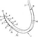
도 1은, 실시예 1을 나타내는 사시도이다.
도 2는, 실시예 1에 관한 주요부의 평면도이다.
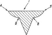
도 3은, 도 2의 A-A 단면도이다.
도 4는, 도 2의 B-B 단면도이다.
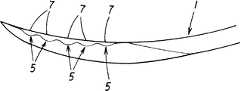
도 5는, 실시예 1에 관한 주요부의 저면도이다.
도 6은, 실시예 1에 관한 주요부의 측면도이다.
도 7은, 실시예 1의 제조방법의 설명도이다.
도 8은, 실시예 1의 제조방법의 설명도이다.
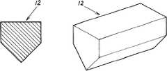
도 9는, 실시예 1의 제조방법의 설명도이다.
도 10은, 실시예 1의 제조방법의 설명도이다.
도 11은, 실시예 1의 제조방법의 설명도이다.
도 12는, 실험체 1에 관한 주요부의 평면도이다.
도 13은, 실험체 2에 관한 주요부의 평면도이다.
도 14는, 실험체 1 및 실험체 2의 자입 성능 비교 실험의 결과를 나타내는 도면이다.
도 15는, 실시예 2에 관한 주요부의 측면도이다.Fig. 1 is a perspective
2 is a plan view of a main part according to the first embodiment.
3 is a sectional view taken along the line AA in Fig.
4 is a cross-sectional view taken along line BB of Fig.
5 is a bottom view of the main part according to the first embodiment.
6 is a side view of a main part according to the first embodiment.
7 is an explanatory diagram of a manufacturing method of the first embodiment.
8 is an explanatory diagram of the manufacturing method of the first embodiment.
9 is an explanatory diagram of the manufacturing method of the first embodiment.
10 is an explanatory diagram of the manufacturing method of the first embodiment.
11 is an explanatory diagram of the manufacturing method of the first embodiment.
12 is a plan view of a main part related to the
13 is a plan view of a main part related to the
Fig. 14 is a diagram showing the results of the comparison of the insertion performance of the
15 is a side view of a main part according to the second embodiment.
적합하다고 생각하는 본 발명의 실시형태를, 도면에 기초하여 본 발명의 작용을 나타내고 간단하게 설명한다.DESCRIPTION OF THE PREFERRED EMBODIMENTS Hereinafter, preferred embodiments of the present invention will be described with reference to the accompanying drawings.
체조직에 자입했을 때, 좌우측부에 마련된 요철부의 가장자리부로 이루어지는 소칼날(6, 7)에 의해서 체조직을 예리하게 찔러 들어가게 되고, 체조직에 자입했을 때의 자입 저항이 가급적으로 저감된다. 이 점에 대해서는 후술하는 자입 성능 비교 시험에 의해 확인이 끝난 상태이다.The body tissue is sharply pierced by the
따라서, 체조직으로의 자입 개시시에서의 자입 저항이 가급적으로 저감되고, 이것을 계기로 해서, 그 후의 기초단측 부위에 있어서의 자입이 원활하게 행해지게도 되고, 따라서, 체조직으로의 부하가 걸리기 어렵고 양호한 봉합 작업이 행해지게 된다.Therefore, the insertion resistance at the time of starting the insertion into the body tissue is reduced as much as possible. With this as an occasion, the insertion at the base end side portion thereafter can be performed smoothly. Therefore, the load on the body tissue is hardly applied, The work is done.
[실시예 1][Example 1]
본 발명의 구체적인 실시예 1에 대해서 도면에 기초하여 설명한다.A first embodiment of the present invention will be described with reference to the drawings.
본 실시예는, 외과 수술에서 사용되는 봉합바늘이다.This embodiment is a suture needle used in surgical operation.
구체적으로는, 바늘 본체(1)는, 도 1에 도시한 바와 같이 적절한 금속제의 직선 막대형상 부재를 오목만곡 형성한 것이고, 그 선단에는 첨예부(1a)가 마련되고, 기초단에는 봉합사(T)를 끼워 삽입 연결하는 단면 원형상의 연결부(1b)(구멍부)가 마련되어 있다.More specifically, the
한편, 바늘 본체(1)의 전체 길이(직선 막대형상 부재의 길이)는 약 13㎜이며, 후술하는 볼록부(4, 5)나 단면 다각형상부를 형성한 후에 오목만곡 형성하고 있다.On the other hand, the entire length of the needle body 1 (the length of the straight bar-shaped member) is about 13 mm, and concave curvature is formed after forming
또, 바늘 본체(1)는, 도 1에 도시한 바와 같이 단면 다각형상부가 형성되어 있다.1, the
본 실시예에서는, 이 단면 다각형상부는 형상이 다른 단면 다각형상부를 바늘 본체(1)의 길이 방향으로 병설해서 구성되어 있고, 구체적으로는, 바늘 본체(1)의 상면(오목만곡 형성한 후의 내면)으로 하여 상기 바늘 본체(1)의 선단으로부터 기초단측 소정 위치 P3까지의 사이에 형성되는 평탄면을 기준으로, 각 단면 다각형상부가 형성되고, 바늘 본체(1)의 선단으로부터 기초단측 소정 위치(P1)(선단으로부터 약 3㎜ 위치)까지의 사이에 마련되는 단면 삼각형상부와, 이 단면 삼각형상부보다 기초단측(기초단측 소정 위치 P1으로부터 기초단측 소정 위치 P2(선단으로부터 약 4.5㎜ 위치)까지의 사이)에 마련되는 단면 오각형상부(베이스 형상)와, 이 단면 오각형상부보다 기초단측(기초단측 소정 위치 P2로부터 기초단측 소정 위치 P3(선단으로부터 약 10.5㎜)까지의 사이)에 마련되는 단면 사각형상부와, 이 단면 사각형상부보다 기초단측(기초단측 소정 위치 P3로부터 기초단까지의 사이)에 마련되는 단면 원형상부로 구성되어 있다.In this embodiment, the upper portion of the cross-section polygon is formed by joining the upper portion of the cross-section polygon having different shapes in the longitudinal direction of the
이 구성으로부터, 바늘 본체(1)의 선단으로부터 기초단측 소정 위치 P3까지의 좌우측부의 상면측에는, 바늘 본체(1)의 길이 방향으로 연장되어 소정 길이를 가지는 첨예의 각(角) 가장자리(2, 3)(봉부)가 마련된다.It is possible to prevent the
한편, 이 단면 다각형상부(단면 삼각형상부, 단면 오각형상부 및 단면 사각형상부)에 있어서의 각 가장자리끼리 사이의 면은 오목 형상면으로 형성해도 좋고, 실제로 단면 삼각형상부의 좌우측면부에는 후술하는 오목홈부(8)가 마련되어 있고, 특수 형상의 단면 삼각형상으로 형성되어 있다.On the other hand, the surfaces between the edges of the cross section of the polygon (cross-section triangle upper, cross-section pentagon upper and cross-section rectangle upper) may be formed by concave surfaces. Actually, 8 are provided, and are formed in the shape of a triangle having a special shape.
또, 바늘 본체(1)의 선단 부위의 좌우측부에는 요철부가 마련되고, 이 요철부의 가장자리부가 소칼날(6, 7)로 설정되어 있다.The left and right side portions of the front end portion of the
구체적으로는, 이 소칼날(6, 7)은, 도 1∼6에 도시한 바와 같이 상기 바늘 본체(1)의 선단 부위(단면 삼각형상부)의 좌우측부에 형성된 봉부(2, 3)(각가장자리) 각각에 볼록부(4, 5)가 복수 마련되고, 이 볼록부(4, 5) 각각의 가장자리부가 소칼날(6, 7)로 설정되어 있고, 따라서, 소칼날(6, 7)은 바늘 본체(1)의 길이 방향으로 복수 병설되어 있다.Specifically, these
즉, 바늘 본체(1)의 좌우측부에는 요철부가 형성되고, 각 볼록부(4, 5)에 있어서의 바늘 본체(1)의 선단측의 가장자리부가 소칼날(6, 7)로 설정되어 있다.That is, the left and right side portions of the
다음에, 이 바늘 본체(1)의 선단 부위의 좌우측부에 마련되는 소칼날(6, 7)의 제조방법에 대해서 설명한다.Next, a method of manufacturing the
먼저, 도 7, 8에 도시한 바와 같이 직선 막대형상 부재의 단면 원형상의 부위(10)를 프레스하여 단면 사각형상의 부위(11)를 형성하고, 계속해서, 도 9에 도시한 바와 같이 이 단면 사각형상의 부위(11)를 절삭하여 단면 오각형상의 부위(12)를 형성한다.First, as shown in Figs. 7 and 8, a
계속해서, 도 10에 도시한 바와 같이 이 단면 오각형상의 부위(12)를 상하의 금형(13A, 13B)으로 프레스하여 좌우측부에 오목홈부(8)를 마련하는 동시에, 좌우측부의 상방 위치에 볼록부(4, 5)를 마련한다. 이 오목홈부(8)는 하금형(13A)의 좌우 부위에 팽출 형성되는 각형상 볼록부(13b)로 형성되고, 볼록부(4, 5) 각각은 하금형(13A)에 오목하게 형성되는 원호 형상 오목부(13a)로 형성된다. 이 원호 형상 오목부(13a)는 하금형(13A)의 길이 방향으로 복수 병설되어 있고, 이 원호 형상 오목부(13a)끼리의 사이에 마련되는, 도시 생략된 원호 형상 볼록부에 의해 바늘 본체(1)의 좌우측부에 마련되는 각 볼록부(4, 5)끼리 사이에는 오목부(오목홈부(8)를 구성하는 오목부도 포함한다)가 형성된다.Subsequently, as shown in Fig. 10, the
계속해서, 도 11에 도시한 바와 같이 단면 삼각형상의 부위(12)의 상부분을 절삭하면, 단면 삼각형상의 부위(12)에는, 상기 단면 삼각형상의 부위(12)의 길이 방향으로 연장되어 소정 길이를 가지는 직선 형상의 봉부(2, 3)(각 가장자리)가 마련되고, 이 봉부(2, 3) 각각에는 볼록부(4, 5)가 마련되고, 이 볼록부(4, 5) 각각의 가장자리부에 의해 소칼날(6, 7)이 형성된다.Then, as shown in Fig. 11, when cutting the upper part of the
한편, 소칼날(6, 7)으로서는, 바늘 본체(1)의 선단 부위의 좌우측부에 복수의 오목부를 간격을 두고 마련하고, 이 오목부 사이의 부분의 가장자리부를 소칼날(6, 7)로 설정하도록 해도 좋다.On the other hand, as the
또, 본 실시예는, 상술한 바와 같이 바늘 본체(1)의 선단 부위의 좌우측부에는, 직선 형상의 오목홈부(8)가 상기 바늘 본체(1)의 길이 방향으로 마련되어 있다. 한편, 오목홈부(8)는 복수개씩 마련하도록 해도 좋다.In this embodiment, linear recessed
이 오목홈부(8)를 마련한 것에 의해, 예를 들면 체조직에 자입한 바늘 본체(1)를 뽑아낼 때, 상기 오목홈부(8)에 의해 체조직과의 접촉 면적이 적어지게 되기 때문에 상기 체조직에 대한 자입 저항 및 인발 저항은 가급적으로 저감되게 된다.By providing the
본 실시예는 상술한 바와 같이 구성했기 때문에, 이 바늘 본체(1)의 선단 부위의 좌우측부에 복수의 볼록부(4, 5)를 마련하고 복수의 소칼날(6, 7)을 마련한 것에 의해, 예를 들면 체조직에 자입했을 때, 이 볼록부(4, 5)의 소칼날(6, 7)에 의해서 체조직을 예리하게 또한 단속적으로 찔러 들어가게 되고, 그 결과, 체조직에 자입했을 때의 자입 저항이 가급적으로 저감되게 된다. 즉, 이 볼록부(4, 5) 각각이 복수 마련되어 복수의 소칼날(6, 7)을 가지는 것에 의해, 이 바늘 본체(1)의 선단부의 좌우측부는 체조직에 자입했을 때에 일정하게 연속하는 찔러 들어감이 아니라, 단속적인 찔러 들어감을 행하는 것으로 양호한 자입이 달성된다.Since the present embodiment is configured as described above, by providing a plurality of
본 출원인은, 상술한 자입 저항이 가급적으로 저감되는 것을 실험에 의해 확인하고 있다.The applicant of the present invention has experimentally confirmed that the aforementioned embedding resistance is reduced as much as possible.
즉, 도 12에 도시한 바와 같이 본 실시예에 관한 구조(바늘 본체(1)의 선단 부위의 좌우측부에 볼록부(4, 5)를 마련한 구조)의 실험체 1과, 도 13에 도시한 바와 같이 바늘 본체(1)의 선단 부위의 좌우측부에 볼록부(4, 5)를 구비하지 않는 실험체 2를 준비하고, 이 양자의 자입 성능 비교 실험을 행하였다.That is, as shown in Fig. 12, the
이 자입 성능 비교 실험은, 실험체 1 및 실험체 2를 동일한 피(被)자입 부재에 대해서 동일한 압력으로 자입했을 때에 생기는 마찰 저항치를 측정해서 비교하는 실험이고, 이 결과를 도 14에 도시한 그래프로 나타내고 있다. 한편, 그래프의 가로축은 실험체 1 및 실험체 2의 선단으로부터의 길이(㎜)이고, 세로축은 피자입 부재에 대해서 자입했을 때에 생기는 마찰 저항치(N)이다.This comparative test is an experiment in which the frictional resistance values generated when the
그래프 중의 흑선은 실험체 1을 나타내고, 백선은 실험체 2를 나타내고 있으며, 이 그래프를 볼 때에, 실험체 1은 실험체 2에 비해서, 바늘 본체(1)의 선단으로부터 최초의 볼록부(4, 5)가 마련되는 약 0.6㎜의 위치로부터 마지막 볼록부(4, 5)가 마련되는 약 2.5㎜의 위치에 걸쳐서 마찰 저항치가 낮다. 이 볼록부(4, 5)가 마련되는 위치를 통과하는 것으로 자입 저항이 낮은 것에 기인하지만, 그 후의 부위에 있어서의 마찰 저항치도 낮다.The black line in the graph represents the
이상으로부터, 이 실험에 의해 바늘 본체(1)의 선단 부위의 좌우측부에 볼록부(4, 5)(소칼날(6, 7))를 마련하는 것이 극히 유효하다는 것을 알 수 있었다.It has been found from the above that it is extremely effective to provide the
따라서, 본 실시예에 의하면, 특히 체조직으로의 자입 개시시에 저항이 걸리는 바늘 본체(1)의 선단 부위인 좌우측부에서의 자입 저항이 가급적으로 저감되고, 이것을 계기로 해서, 그 후의 바늘 본체(1)의 기초단측 부위에 있어서의 자입이 원활하게 행해지게도 되고, 따라서, 체조직으로의 부하가 걸리기 어렵고 양호한 봉합 작업이 행해지게 된다.Therefore, according to the present embodiment, in particular, the insertion resistance at the left and right side portions, which are the front end portions of the
또, 본 실시예는, 바늘 본체(1)의 선단 부위의 좌우측부에 오목홈부(8)가 바늘 본체(1)의 길이 방향으로 마련되어 있기 때문에, 이 오목홈부(8)의 존재에 의해서도 체조직과의 접촉 면적이 적어지게 되므로 상기 체조직에 대한 자입 저항이 가급적으로 저감된다.In the present embodiment, since the
또, 본 실시예는, 바늘 본체(1)에 단면 다각형상부가 형성되어 있고, 이 단면 다각형상부에 있어서의 각가장자리에 의해서 체조직을 예리하게 찔러 들어가게 되어, 체조직에 자입했을 때의 자입 저항이 가급적으로 저감되게 된다.In the present embodiment, the
또, 본 실시예에 관한 단면 다각형상부는 형상이 다른 단면 다각형상부를 바늘 본체(1)의 길이 방향으로 병설해서 구성되어 있기 때문에, 자입 도중에 형상 변화시키는 것으로 찔러 들어감 작용을 발생시키게 되어, 체조직에 자입했을 때의 자입 저항이 가급적으로 저감되게 된다.In addition, since the upper part of the cross-section polygon according to the present embodiment is constituted by arranging the upper part of the cross-section polygon having the different shape in the longitudinal direction of the
구체적으로는, 본 실시예는, 단면 다각형상부는 바늘 본체(1)의 선단측에 마련되는 단면 삼각형상부와, 이 단면 삼각형상부보다 기초단측에 마련되는 단면 오각형상부 및 단면 사각형상부로 구성되어 있기 때문에, 자입 도중에 각의 수가 바뀌는 형상 변화시키는 것으로 찔러 들어감 작용을 발생시키게 되어, 체조직에 자입했을 때의 자입 저항을 가급적으로 저감할 수 있게 된다.Specifically, in the present embodiment, the upper portion of the cross-section polygon is composed of a triangular upper section of the cross section provided at the distal end side of the
[실시예 2][Example 2]
본 발명의 구체적인 실시예 2에 대해서 도면에 기초하여 설명한다.A second embodiment of the present invention will be described with reference to the drawings.
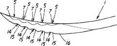
본 실시예는, 바늘 본체(1)의 좌우측부에 볼록부(4, 5) 및 소칼날(6, 7)을 마련하는 것 외에도, 바늘 본체(1)의 선단부로 하여 단면 삼각형상부의 외면부(하면부)에 요철부가 마련되고, 이 요철부의 가장자리부가 소칼날(15)로 설정되어 있다.The present embodiment is different from the first embodiment in that the
구체적으로는, 이 소칼날(15)은, 도 15에 도시한 바와 같이 상기 바늘 본체(1)의 선단부(단면 삼각형상부)의 외면부에 형성된 봉부(16)(각가장자리)에 바늘 본체(1)의 축심 방향으로 향해서 오목부(14)를 복수 마련하고, 이 오목부(14)의 가장자리부가 볼록 형상의 소칼날(15)로 설정되어 있고, 소칼날(15)은 바늘 본체(1)의 길이 방향으로 복수 병설되어 있다.15, the
이 오목부(14)는 상술한 좌우측부의 볼록부(4, 5)와 동일하고, 프레스에 의해 형성해도 좋고, 절삭에 의해 형성해도 좋다.The
한편, 본 발명은, 실시예 1, 2에 한정되는 것이 아니고, 각 구성 요건의 구체적 구성은 적절히 설계할 수 있는 것이다.On the other hand, the present invention is not limited to
Claims (16)
Translated fromKorean상기 바늘 본체는 선단으로부터 기초단까지 오목만곡 형상으로 형성되어 있는 것을 특징으로 하는 봉합바늘.The left and right side portions of the tip end portion of the needle body are provided with concave and convex portions, the edge portion of the concave and convex portion is set to a small blade,
Wherein the needle body is formed in a concave curved shape from a tip end to a base end.
상기 소칼날은 상기 요철부의 볼록부의 가장자리부에 마련되어 있는 것을 특징으로 하는 봉합바늘.The method according to claim 1,
Wherein the knife blade is provided at an edge of a convex portion of the concave-convex portion.
상기 볼록부는 바늘 본체의 길이 방향으로 복수 마련되어 있는 것을 특징으로 하는 봉합바늘.3. The method of claim 2,
Wherein a plurality of the convex portions are provided in the longitudinal direction of the needle body.
상기 바늘 본체의 선단 부위는 단면 삼각형상으로 구성되어 있고, 이 단면 삼각형상의 선단 부위의 좌우측 가장자리 각각에 상기 요철부가 마련되어 있는 것을 특징으로 하는 봉합바늘.4. The method according to any one of claims 1 to 3,
Wherein the tip end portion of the needle body is formed in a triangular shape in cross section, and the concave-convex portion is provided on each of left and right edges of a tip end portion of the triangle-shaped cross section.
상기 바늘 본체는 선단으로부터 기초단까지 오목만곡 형상으로 형성되어 있는 것을 특징으로 하는 봉합바늘.A plurality of convex portions are provided on the left and right side portions of the front end portion of the needle body, the edge portions of the left and right convex portions are set to be small blade edges,
Wherein the needle body is formed in a concave curved shape from a tip end to a base end.
좌우의 상기 볼록부 각각은 상기 바늘 본체의 길이 방향으로 복수 병설되어 있는 것을 특징으로 하는 봉합바늘.6. The method of claim 5,
Wherein a plurality of the convex portions on the left and right sides are arranged in parallel in the longitudinal direction of the needle body.
상기 바늘 본체의 선단 부위의 좌우측부에는, 상기 바늘 본체의 길이 방향으로 연장되는 직선 형상의 봉부(峰部)가 마련되고, 이 봉부 각각에 상기 볼록부가 마련되어 있는 것을 특징으로 하는 봉합바늘.The method according to claim 5 or 7,
Wherein the right and left side portions of the distal end portion of the needle body are provided with linear rods extending in the longitudinal direction of the needle body and the convex portions are provided in each of the rods.
Applications Claiming Priority (3)
| Application Number | Priority Date | Filing Date | Title |
|---|---|---|---|
| JPJP-P-2009-298915 | 2009-12-28 | ||
| JP2009298915AJP5188491B2 (en) | 2009-12-28 | 2009-12-28 | Suture needle |
| PCT/JP2010/073383WO2011081100A1 (en) | 2009-12-28 | 2010-12-24 | Suture needle |
Publications (2)
| Publication Number | Publication Date |
|---|---|
| KR20120101709A KR20120101709A (en) | 2012-09-14 |
| KR101458680B1true KR101458680B1 (en) | 2014-11-05 |
Family
ID=44226506
Family Applications (1)
| Application Number | Title | Priority Date | Filing Date |
|---|---|---|---|
| KR1020127018231AActiveKR101458680B1 (en) | 2009-12-28 | 2010-12-24 | Suture needle |
Country Status (9)
| Country | Link |
|---|---|
| US (1) | US20120259359A1 (en) |
| EP (1) | EP2520231A4 (en) |
| JP (1) | JP5188491B2 (en) |
| KR (1) | KR101458680B1 (en) |
| CN (1) | CN102686168B (en) |
| BR (1) | BR112012016063A2 (en) |
| CA (1) | CA2782301C (en) |
| MX (1) | MX2012007550A (en) |
| WO (1) | WO2011081100A1 (en) |
Families Citing this family (2)
| Publication number | Priority date | Publication date | Assignee | Title |
|---|---|---|---|---|
| JP6668076B2 (en)* | 2016-01-06 | 2020-03-18 | マニー株式会社 | Medical suture needle |
| JP7133273B2 (en)* | 2019-08-28 | 2022-09-08 | マニー株式会社 | medical suture needle |
Citations (1)
| Publication number | Priority date | Publication date | Assignee | Title |
|---|---|---|---|---|
| JP2004531317A (en) | 2001-05-14 | 2004-10-14 | リンバテック バイオマテリアルズ オサケユイチア | Microtraumatic surgical device for tissue treatment |
Family Cites Families (13)
| Publication number | Priority date | Publication date | Assignee | Title |
|---|---|---|---|---|
| US4660559A (en)* | 1983-09-19 | 1987-04-28 | Ethicon, Inc. | Sterile surgical needles with a hard sharp cutting edge and method for producing the same |
| US5002564A (en)* | 1989-06-19 | 1991-03-26 | Ethicon, Inc. | Surgical needle configuration with spatula geometry |
| JP3442153B2 (en)* | 1994-08-23 | 2003-09-02 | マニー株式会社 | Suture Needle Mold and Suture Needle |
| US5787591A (en)* | 1996-10-15 | 1998-08-04 | Long Shye Enterprise Co., Ltd. | Knife blade edge |
| JP3417263B2 (en)* | 1997-08-29 | 2003-06-16 | マニー株式会社 | Suture needle |
| JP2000139931A (en) | 1998-11-17 | 2000-05-23 | Keisei Ika Kogyo Kk | Micro-suturing needle and its manufacture |
| JP4318110B2 (en)* | 1999-08-26 | 2009-08-19 | マニー株式会社 | Medical suturing needle and method for producing medical suturing needle |
| US7112208B2 (en)* | 2001-08-06 | 2006-09-26 | Morris John K | Compact suture punch with malleable needle |
| AU2003251909B2 (en)* | 2002-07-17 | 2008-11-20 | Covidien Lp | Surgical suture needle |
| DE10259642A1 (en)* | 2002-12-18 | 2004-07-22 | Fssb Chirurgische Nadeln Gmbh | Surgical needle, for sutures through tissue, is polished mechanically to give structured projections and recesses, to be treated with a non-stick materials and dark gilding for low contrast without gloss |
| JP4243220B2 (en)* | 2004-05-26 | 2009-03-25 | 株式会社秋山製作所 | Suture needle |
| JP4410210B2 (en) | 2006-03-31 | 2010-02-03 | ケイセイ医科工業株式会社 | Suture needle |
| US20100036415A1 (en)* | 2008-08-07 | 2010-02-11 | Tyco Healthcare Group Lp | Surgical needle with reduced contact area |
- 2009
- 2009-12-28JPJP2009298915Apatent/JP5188491B2/enactiveActive
- 2010
- 2010-12-24KRKR1020127018231Apatent/KR101458680B1/enactiveActive
- 2010-12-24BRBR112012016063Apatent/BR112012016063A2/ennot_activeApplication Discontinuation
- 2010-12-24WOPCT/JP2010/073383patent/WO2011081100A1/enactiveApplication Filing
- 2010-12-24USUS13/517,926patent/US20120259359A1/ennot_activeAbandoned
- 2010-12-24EPEP10840956.6Apatent/EP2520231A4/ennot_activeWithdrawn
- 2010-12-24MXMX2012007550Apatent/MX2012007550A/ennot_activeApplication Discontinuation
- 2010-12-24CACA2782301Apatent/CA2782301C/enactiveActive
- 2010-12-24CNCN201080059493.6Apatent/CN102686168B/enactiveActive
Patent Citations (1)
| Publication number | Priority date | Publication date | Assignee | Title |
|---|---|---|---|---|
| JP2004531317A (en) | 2001-05-14 | 2004-10-14 | リンバテック バイオマテリアルズ オサケユイチア | Microtraumatic surgical device for tissue treatment |
Also Published As
| Publication number | Publication date |
|---|---|
| JP2011136087A (en) | 2011-07-14 |
| HK1173636A1 (en) | 2013-05-24 |
| CN102686168B (en) | 2015-06-17 |
| EP2520231A4 (en) | 2016-09-28 |
| US20120259359A1 (en) | 2012-10-11 |
| CA2782301A1 (en) | 2011-07-07 |
| CA2782301C (en) | 2015-01-20 |
| MX2012007550A (en) | 2012-07-23 |
| EP2520231A1 (en) | 2012-11-07 |
| CN102686168A (en) | 2012-09-19 |
| WO2011081100A1 (en) | 2011-07-07 |
| JP5188491B2 (en) | 2013-04-24 |
| KR20120101709A (en) | 2012-09-14 |
| BR112012016063A2 (en) | 2016-08-16 |
Similar Documents
| Publication | Publication Date | Title |
|---|---|---|
| JP5643742B2 (en) | Suture needle | |
| JP5566045B2 (en) | Medical suture needle | |
| CN101594828B (en) | Suturing needle | |
| DE102009029608B4 (en) | tool knife | |
| EP2679186B1 (en) | Instrument for vessel fusion and separation | |
| JP4884955B2 (en) | Needle | |
| CN110882089B (en) | Strong sawtooth wire | |
| KR101458680B1 (en) | Suture needle | |
| CN109864772A (en) | Microsurgical instruments and improvements in handles | |
| JP6423203B2 (en) | Medical suture needle | |
| JP5006868B2 (en) | Suture needle | |
| CN108472033B (en) | medical suture needle | |
| JP2014008097A (en) | Suture needle | |
| TWI524874B (en) | Suture needle | |
| JP3811913B2 (en) | Method for manufacturing surgical suture needle | |
| CN114126501B (en) | Medical suture needle | |
| HK1173636B (en) | Suture needle | |
| KR101312357B1 (en) | Needle for rhizotomy | |
| WO2016039333A1 (en) | Puncture device | |
| JP3067422U (en) | Embroidery thread cutting receiver |
Legal Events
| Date | Code | Title | Description |
|---|---|---|---|
| E13-X000 | Pre-grant limitation requested | St.27 status event code:A-2-3-E10-E13-lim-X000 | |
| PA0105 | International application | St.27 status event code:A-0-1-A10-A15-nap-PA0105 | |
| PG1501 | Laying open of application | St.27 status event code:A-1-1-Q10-Q12-nap-PG1501 | |
| A201 | Request for examination | ||
| PA0201 | Request for examination | St.27 status event code:A-1-2-D10-D11-exm-PA0201 | |
| E902 | Notification of reason for refusal | ||
| PE0902 | Notice of grounds for rejection | St.27 status event code:A-1-2-D10-D21-exm-PE0902 | |
| E13-X000 | Pre-grant limitation requested | St.27 status event code:A-2-3-E10-E13-lim-X000 | |
| P11-X000 | Amendment of application requested | St.27 status event code:A-2-2-P10-P11-nap-X000 | |
| P13-X000 | Application amended | St.27 status event code:A-2-2-P10-P13-nap-X000 | |
| E701 | Decision to grant or registration of patent right | ||
| PE0701 | Decision of registration | St.27 status event code:A-1-2-D10-D22-exm-PE0701 | |
| GRNT | Written decision to grant | ||
| PR0701 | Registration of establishment | St.27 status event code:A-2-4-F10-F11-exm-PR0701 | |
| PR1002 | Payment of registration fee | St.27 status event code:A-2-2-U10-U12-oth-PR1002 Fee payment year number:1 | |
| PG1601 | Publication of registration | St.27 status event code:A-4-4-Q10-Q13-nap-PG1601 | |
| FPAY | Annual fee payment | Payment date:20170406 Year of fee payment:4 | |
| PR1001 | Payment of annual fee | St.27 status event code:A-4-4-U10-U11-oth-PR1001 Fee payment year number:4 | |
| FPAY | Annual fee payment | Payment date:20180502 Year of fee payment:5 | |
| PR1001 | Payment of annual fee | St.27 status event code:A-4-4-U10-U11-oth-PR1001 Fee payment year number:5 | |
| PR1001 | Payment of annual fee | St.27 status event code:A-4-4-U10-U11-oth-PR1001 Fee payment year number:6 | |
| PR1001 | Payment of annual fee | St.27 status event code:A-4-4-U10-U11-oth-PR1001 Fee payment year number:7 | |
| PR1001 | Payment of annual fee | St.27 status event code:A-4-4-U10-U11-oth-PR1001 Fee payment year number:8 | |
| PR1001 | Payment of annual fee | St.27 status event code:A-4-4-U10-U11-oth-PR1001 Fee payment year number:9 | |
| PR1001 | Payment of annual fee | St.27 status event code:A-4-4-U10-U11-oth-PR1001 Fee payment year number:10 | |
| PR1001 | Payment of annual fee | St.27 status event code:A-4-4-U10-U11-oth-PR1001 Fee payment year number:11 | |
| PR1001 | Payment of annual fee | St.27 status event code:A-4-4-U10-U11-oth-PR1001 Fee payment year number:12 |