KR101457959B1 - Robot cleaner inlet of the supporting device - Google Patents
Robot cleaner inlet of the supporting deviceDownload PDFInfo
- Publication number
- KR101457959B1 KR101457959B1KR1020120151831AKR20120151831AKR101457959B1KR 101457959 B1KR101457959 B1KR 101457959B1KR 1020120151831 AKR1020120151831 AKR 1020120151831AKR 20120151831 AKR20120151831 AKR 20120151831AKR 101457959 B1KR101457959 B1KR 101457959B1
- Authority
- KR
- South Korea
- Prior art keywords
- suction port
- robot cleaner
- linkage
- main body
- guide groove
- Prior art date
- Legal status (The legal status is an assumption and is not a legal conclusion. Google has not performed a legal analysis and makes no representation as to the accuracy of the status listed.)
- Expired - Fee Related
Links
Images


Classifications
- A—HUMAN NECESSITIES
- A47—FURNITURE; DOMESTIC ARTICLES OR APPLIANCES; COFFEE MILLS; SPICE MILLS; SUCTION CLEANERS IN GENERAL
- A47L—DOMESTIC WASHING OR CLEANING; SUCTION CLEANERS IN GENERAL
- A47L9/00—Details or accessories of suction cleaners, e.g. mechanical means for controlling the suction or for effecting pulsating action; Storing devices specially adapted to suction cleaners or parts thereof; Carrying-vehicles specially adapted for suction cleaners
- A47L9/02—Nozzles
- A—HUMAN NECESSITIES
- A47—FURNITURE; DOMESTIC ARTICLES OR APPLIANCES; COFFEE MILLS; SPICE MILLS; SUCTION CLEANERS IN GENERAL
- A47L—DOMESTIC WASHING OR CLEANING; SUCTION CLEANERS IN GENERAL
- A47L2201/00—Robotic cleaning machines, i.e. with automatic control of the travelling movement or the cleaning operation
Landscapes
- Engineering & Computer Science (AREA)
- Mechanical Engineering (AREA)
- Nozzles For Electric Vacuum Cleaners (AREA)
Abstract
Translated fromKoreanDescription
Translated fromKorean본 발명은 로봇청소기의 흡입구에 설치되는 흡입구 지지장치에 관한 것으로서 더욱 상세하게는 로봇청소기 본체의 전방에 설치되며 로봇청소기가 주행중일 때 흡입구가 바닥면과 밀착되도록 하강하고, 주행을 완료하면 흡입구가 상승하여 흡입구의 파손을 방지하도록 로봇청소기 본체에 설치되는 로봇청소기의 흡입구 지지장치에 관한 것이다.The robot cleaner is installed in front of the robot cleaner main body. When the robot cleaner is running, the suction port is lowered to closely contact the bottom surface. When the robot cleaner is running, So as to prevent damage to the suction port. The present invention relates to a suction port support apparatus of a robot cleaner installed in a robot cleaner main body.
일반적으로 로봇(Robot)은 인간의 형상을 한 인형 내부에 기계장치를 조립해 넣고 인간을 대신하여 동작하는 자동인형을 말하는 것으로 산업용 로봇, 의료용 로봇 등으로 나눌 수 있으며 현재 다양한 분야에서 사용되고 있다. 이와 같은 로봇은 인간의 편리함을 추구하기 위하여 오래전부터 개발되어 왔으며 그 범위 역시 점차적으로 증가하고 있는 실정이다.In general, a robot is an automatic doll that operates in place of a human by assembling a mechanical device into a human doll. It can be divided into an industrial robot, a medical robot, and the like, and is currently used in various fields. Such a robot has been developed for a long time in order to pursue the convenience of the human being, and the range of the robot is also gradually increasing.
인간의 편리함을 추구하기 위하여 개발된 로봇 중에 하나인 로봇청소기는 사용자의 조작 없이 청소하고자 하는 구역내를 스스로 주행하면서 바닥면에 떨어진 먼지나 이물질 등을 흡입함으로써 실내를 항상 쾌적한 상태로 유지시켜 줄 수 있다. 따라서 현재 일반가정에서 많이 사용하고 있는 추세이며 구입가격면에서 저렴해지고 있어 로봇청소기를 사용하는 가구의 수가 증가하고 있다.The robot cleaner, which is one of the robots developed to pursue the convenience of human beings, keeps the room in a pleasant state by suctioning dust and foreign substances falling on the floor surface while driving itself within the area to be cleaned without user's operation have. Therefore, it is a trend that is widely used in general households, and it is becoming cheaper in terms of purchase price, so that the number of households using the robot cleaner is increasing.
종래의 로봇청소기는 단순한 평행이동만 가능하고, 바닥의 작은 입자들만 흡입할 수 있도록 제작되었다. 이러한 종래의 로봇청소기는 바닥의 굴곡이나 문지방 등에 의해 흡입구가 파손되고 흡입구 내부에 일정 크기 이상의 이물질이 인입되면 막힘현상이 자주 발생하게 되는 문제점이 있었다.Conventional robotic vacuum cleaners are designed to allow only simple parallel movement and only small particles in the bottom can be inhaled. In such a conventional robot cleaner, there is a problem that clogging occurs frequently when the suction port is broken due to the bending of the floor, the rim of the floor, or the like and a foreign substance having a certain size or more is drawn in the suction port.
또한 흡입구가 바닥의 굴곡이나 문지방 등에 부딪혀 파손되면 흡입구의 파손된 부위로 흡입되는 압력이 유출되어 흡입능력이 저하되는 문제점과 집진기의 모터에 부하가 가중되어 전력의 소비가 상승하고 청소효율이 떨어지게 되는 복합적인 문제점이 발생하였다.In addition, if the suction port is broken due to the bending of the floor or the rim of the floor, etc., the suction force of the suction port may be deteriorated due to the suction of the suction pressure to the damaged portion of the suction port, and the load on the motor of the dust collector may be increased, Complex problems have arisen.
이와 같은 문제점을 해결하기 위하여 흡입구에 청소용 브러쉬가 장착되는 청소용 로봇이 제작되어 왔으나, 브러쉬가 전방에 형성된 먼지나 이물질을 청소기 외측으로 밀어내어 청소효율이 감소되고, 브러쉬가 바닥에 부딪히는 소음이 심하게 발생하며, 브러쉬를 회전시키기 위하여 고출력의 모터가 장착되므로 제작비가 상승하게 되는 문제점이 있었다.In order to solve such a problem, a cleaning robot having a cleaning brush mounted on a suction port has been manufactured. However, cleaning efficiency is reduced by pushing out dust or foreign matter formed on the front side of the brush to the outside of the cleaner, and a noise And a high-output motor is mounted to rotate the brush, so that the production cost is increased.
상기와 같은 문제점을 해결하고자 안출된 본 발명의 목적은 바닥면의 이물질이나 문지방으로부터 로봇청소기의 흡입구의 파손을 방지하고 바닥의 장애물 등을 회피하여 청소가 가능한 로봇청소기의 흡입구 지지장치를 제공한다.An object of the present invention is to provide a suction port support apparatus for a robot cleaner capable of preventing breakage of a suction port of a robot cleaner from a foreign matter or a door surface of a floor and avoiding obstacles on the floor.
또한 본 발명은 흡입구의 상하이동시키기 위하여 흡입구의 상하 이동을 제어하고, 장애물의 충돌 여부를 파악할 수 있도록 감지센서를 구비하여 흡입구의 파손을 방지하는 로봇청소기의 흡입구 지지장치를 제공하는 것을 목적으로 한다.Another object of the present invention is to provide a suction port support apparatus for a robot cleaner, which is provided with a detection sensor for controlling the up and down movement of the suction port in order to move the suction port upward and downward, .
본 발명의 로봇청소기의 흡입구 지지장치는 내부에 공기를 흡입하는 집진기(110)가 설치되며 이동하는 청소기 본체(100); 상기 청소기 본체(100)의 내부에 설치되고, 회전하는 회전축(210)이 형성되는 구동모터(200); 미리 설정된 제1 지점(S1)에서 미리 설정된 제2 지점(S2)으로 회전하도록 일측이 상기 회전축(210)과 연결되는 제1 연결대(300); 상기 제1 연결대(300)가 상기 제1 지점(S1)에서 상기 제2 지점(S2)으로 회전하는 경우 수직방향을 유지하거나 후방으로 기울어지도록 일측이 상기 제1 연결대(300)의 타측과 연결되며, 상기 청소기 본체(100)의 이동방향과 반대방향으로 설정된 회전각도(θ)만큼 회전 가능하도록 설치되는 제2 연결대(400); 흡입호스(520)에 의해 상기 집진기(110)와 연결되도록 연결홀(510)이 형성되고, 상기 제2 연결대(400)의 타측과 회전 가능하도록 연결되는 흡입구(500);를 포함하는 것을 특징으로 한다.The suction port support device of the robot cleaner of the present invention includes a cleaner
본 발명에 있어서, 상기 제1 연결대(300)의 타측에는 삽입홈(311)이 형성되는 보스부(310)가 돌출 형성되고, 상기 제2 연결대(400)의 일측에는 상기 삽입홈(311)에 삽입되는 삽입로드(410)가 돌출 형성되는 것을 특징으로 한다.A
본 발명에 있어서, 상기 제1 연결대(300)의 삽입홈(311)에는 상기 삽입홈(311)의 외측방향으로 호(弧)형상을 가지도록 형성되는 안내홈(312)이 형성되고, 상기 제2 연결대(400)의 삽입로드(410)에는 상기 안내홈(312)에 삽입되어 상기 안내홈(312)을 따라 삽입로드(410)와 일체로 회전하는 안내돌기(411)가 형성되는 것을 특징으로 한다.In the present invention, a
본 발명에 있어서, 상기 안내홈(312)과 상기 안내돌기(411) 사이에는 일측이 상기 안내홈(312)의 내측면에 지지되고 타측이 상기 안내돌기(411)에 지지되어 상기 제2 연결대(400)를 탄성 지지하는 탄성부재(600)가 구비되는 것을 특징으로 한다.One side of the
본 발명에 있어서, 상기 구동모터(200)는 스텝 모터인 것을 특징으로 한다.In the present invention, the drive motor (200) is a stepping motor.
본 발명은 로봇청소기의 전방에 설치되는 흡입구 지지장치가 흡입구와 체결되고 흡입구 지지장치는 로봇청소기의 진행방향과 반대방향으로 회전이 가능하여 로봇청소기 흡입구가 바닥의 장애물과 충돌했을 때 파손되는 것을 방지한다.The present invention is characterized in that the suction port support device installed in front of the robot cleaner is fastened to the suction port and the suction port support device can be rotated in the direction opposite to the traveling direction of the robot cleaner to prevent the suction port of the robot cleaner from being damaged when colliding with an obstacle on the floor do.
본 발명은 흡입구가 상하방향으로 이동할 수 있도록 흡입구 지지장치를 회전시키는 구동모터를 로봇청소기 내부에 설치하였고, 구동모터가 회전함에 따라 흡입구가 상승하여 문지방이나 바닥의 장애물 등을 회피할 수 있기 때문에 흡입구의 파손을 방지하는 효과가 발생한다.In the present invention, a driving motor for rotating the suction port supporting device so that the suction port can move in the up and down direction is installed inside the robot cleaner, and since the suction port rises as the driving motor rotates, it is possible to avoid obstacles, There is generated an effect of preventing the breakage.
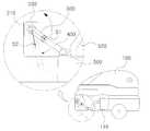
도 1 은 본 발명의 로봇청소기를 나타낸 측면도.
도 2 는 본 발명의 제1 연결대의 작동방법을 나타낸 측면도.
도 3 은 본 발명의 제2 연결대의 작동방법을 나타낸 측면도.
도 4 은 본 발명의 지지장치의 주요부를 나타낸 사시도.
도 5 는 본 발명의 지지장치의 탄성부재를 나타낸 사시도.1 is a side view showing a robot cleaner of the present invention.
2 is a side view illustrating a method of operating the first link of the present invention.
3 is a side view illustrating a method of operating the second link of the present invention.
4 is a perspective view showing a main part of a supporting device of the present invention;
5 is a perspective view showing an elastic member of the support device of the present invention.
이하, 첨부한 도면을 참조하여 본 발명의 실시예에 대하여 본 발명이 속하는 기술 분야에서 통상의 지식을 가진 자가 용이하게 실시할 수 있도록 상세히 설명한다. 그러나 본 발명은 여러 가지 상이한 형태로 구현될 수 있으며 여기에서 설명하는 실시예에 한정되지 않는다.Hereinafter, embodiments of the present invention will be described in detail with reference to the accompanying drawings so that those skilled in the art can easily carry out the present invention. The present invention may, however, be embodied in many different forms and should not be construed as limited to the embodiments set forth herein.
도 1 은 본 발명의 로봇청소기를 나타낸 측면도, 도 2 는 본 발명의 제1 연결대의 작동방법을 나타낸 측면도, 도 3 은 본 발명의 제2 연결대의 작동방법을 나타낸 측면도, 도 4 은 본 발명의 지지장치의 주요부를 나타낸 사시도, 도 5 는 본 발명의 지지장치의 탄성부재를 나타낸 사시도이다.FIG. 1 is a side view of the robot cleaner of the present invention, FIG. 2 is a side view showing a method of operating the first connecting rod of the present invention, FIG. 3 is a side view showing a method of operating the second connecting rod of the present invention, Fig. 5 is a perspective view showing an elastic member of the supporting device of the present invention. Fig.
도 1 을 참조하면 본 발명은 청소기 본체(100)를 갖는다. 청소기 본체(100)는 내부에 공기를 흡입하는 집진기(110)가 구비된다. 집진기(110)는 외부의 먼지 등을 흡입 및 보관할 수 있는 용도로 설치된다. 청소기 본체(100)는 이동할 수 있도록 좌우측에 구동바퀴가 설치되며 구동바퀴가 회전함에 따라 전방으로 이동할 수 있다.Referring to FIG. 1, the present invention has a cleaner
도 1 을 참조하면 청소기 본체(100)에는 구동모터(200)가 설치된다. 구동모터(200)는 전력이 공급되면 회전하는 회전축(210)을 포함한다. 구동모터(200)는 설정된 각도만큼 반복 회전할 수 있도록 스텝모터(Stepper motor)로 설치될 수 있다. 스텝모터는 일정한 전력이 공급되면 일정한 각도만큼 회전하는 모터이다.Referring to FIG. 1, a
도 1 및 도 2 를 참조하면 회전축(210)과 연결되는 제1 연결대(300)가 형성된다. 제1 연결대(300)는 소정의 두께를 가지며 상하로 연장되는 직사각형의 판 형상으로 형성될 수 있다. 제1 연결대(300)는 일측이 회전축(210)에 연결되며 회전축(210)이 회전함에 따라 상하방향으로 회전할 수 있다. 이때 제1 연결대(300)의 타측은 미리 설정된 제1 지점(S1)에서 미리 설정된 제2 지점(S2)으로 이동하도록 회전축(210)을 중심으로 회전한다. 제1 지점(S1)은 회전축(210)의 후방일 수 있고 제2 지점(S2)은 제1 지점(S1)보다 하측에 위치할 수 있다. 즉 제1 연결대(300)는 회전축(210)을 중심으로 회전하되, 제1 연결대(300)의 타측은 제1 지점(S1)인 회전축(210)의 후방에서 제1 지점(S1)의 하측에 위치한 제2 지점(S2)으로 이동한다.Referring to FIGS. 1 and 2, a
도 2 의 (a)를 참조하면 제1 연결대(300)의 타측이 위치하는 제2 지점(S2)은 회전축(210)의 하측 후방에 위치할 수 있다.Referring to FIG. 2 (a), the second point S2 at which the other side of the
도 2 의 (b)를 참조하면 제1 연결대(300)의 타측이 위치하는 제2 지점(S2)은 회전축(210)의 전방에 위치할 수 있다.Referring to FIG. 2 (b), the second point S2 where the other side of the
도 2 의 (c)를 참조하면 제1 연결대(300)의 타측이 위치하는 제2 지점(S2)은 회전축(210)과 수직선상에 위치할 수 있다.Referring to FIG. 2 (c), the second point S2 at which the other side of the
이와 같이 제2 지점(S2)은 다양한 위치로 지정될 수 있다.Thus, the second point S2 can be specified in various positions.
도 3 을 참조하면 일측이 제1 연결대(300)의 타측에 연결되는 제2 연결대(400)가 형성된다. 제2 연결대(400)는 제1 연결대(300)가 제1 지점(S1)에서 제2 지점(S2)으로 회전하는 경우 적어도 수직방향을 유지하며 세워지거나 후방으로 기울어질 수 있도록 제1 연결대(300)의 타측에 연결된다. 이때 제1 연결대(300)에 연결된 제2 연결대(400)는 청소기 본체(100)의 이동방향과 반대방향으로 설정된 회전각도(θ)만큼 회전 가능하게 설치된다.Referring to FIG. 3, a
도 1 및 도 3 을 참조하면 제2 연결대(400)의 타측에 연결되는 흡입구(500)가 형성된다. 흡입구(500)는 제2 연결대(400)의 타측과 회전 가능하도록 연결된다. 흡입구(500)의 일측에는 연결홀(510)이 형성되며, 일측이 연결홀(510)과 연결되고 타측이 집진기(110)에 연결되는 흡입호스(520)를 통하여 청소기 본체(100)에 설치된 집진기(110)와 흡입구(500)는 상호 연결된다. 흡입호스(520)는 주름관 및 플랙시블 튜브 등으로 설치될 수 있다. 흡입구(500)는 제2 연결대(400)가 청소기 본체(100)의 이동방향과 반대방향으로 회전되는 경우 자중(自重)에 의해서 바닥면과 수평을 이루도 제2 연결대(400)의 타측에 연결된다.Referring to FIGS. 1 and 3, an
도 3 을 참조하면 청소기 본체(100)가 전방으로 이동할 때 흡입구(500)는 바닥면에 밀착된다. 이때 집진기(110)로부터 흡입력이 흡입구(500)로 전달되어 바닥면에 존재하는 이물질 및 먼지 등을 흡입한다. 청소기 본체(100)가 전방으로 이동하면 흡입구(500)는 청소기 본체(100)에 끌리면서 이동한다. 흡입구(500)가 장애물 등에 걸리면 흡입구(500)와 연결된 제2 연결대(400)가 청소기 본체(100)의 진행방향의 구동력에 의해 청소기 본체(100)의 이동방향과 반대방향인 회전각도(θ)의 범위내에서 회전한다. 따라서 청소기 본체(100)가 장애물 등에 구애받지 않고 원활하게 이동할 수 있다.Referring to FIG. 3, when the cleaner
도 4 를 참조하면 제1 연결대(300)의 타측에는 보스부(310)가 형성된다. 보스부(310)는 제1 연결대(300)의 타측에 돌출 형성되고, 중앙에는 삽입홈(311)이 함입 형성된다.Referring to FIG. 4, a
도 4 를 참조하면 제2 연결대(400)의 일측에는 삽입로드(410)가 돌출 형성된다. 삽입로드(410)는 제1 연결대(300)의 삽입홈(311)에 회전가능하도록 끼워진다. 따라서 제1 연결대(300)와 제2 연결대(400)는 상호 회전가능하도록 연결된다.Referring to FIG. 4, an
도 5 를 참조하면 제1 연결대(300)의 삽입홈(311)에는 안내홈(312)이 형성된다. 안내홈(312)은 삽입홈(311)의 외측방향으로 호(弧)형상을 가지도록 형성된다. 안내홈(312)은 상기 제2 연결대(400)가 청소기 본체(100)의 이동방향과 반대방향으로 회전하는 회전각도(θ)와 동일한 각도의 호(弧)형상으로 형성된다.Referring to FIG. 5, the
도 5 를 참조하면 제2 연결대(400)의 삽입로드(410)에는 안내돌기(411)가 돌출 형성된다. 안내돌기(411)는 삽입로드(410)의 둘레면으로부터 외측방향으로 돌출 형성된다. 안내돌기(411)는 제1 연결대(300)의 안내홈(311)에 삽입되며 안내홈(312)을 따라 제2 연결대(400)의 삽입로드(410)와 일체로 회전한다. 제2 연결대(400)는 안내홈(312)의 호(弧)의 각도 즉 제2 연결대(400)의 회전각도(θ)의 범위 내에서 회전할 수 있다. 이때 제2 연결대(400)는 회전축(210)의 후방으로 경사지는 것이 바람직하다.Referring to FIG. 5, a
도 5 를 참조하면 안내홈(312)에는 탄성부재(600)가 설치된다. 탄성부재(600)는 안내홈(312)과 안내돌기(411) 사이에 설치된다. 즉 탄성부재(600)의 일측이 안내홈(312)의 내측면에 지지되고 타측이 안내돌기(411)의 외측면에 지지되어 제2 연결대(400)를 탄성 지지한다. 즉 탄성부재(600)는 제2 연결대(400)를 청소기 몸체(100)의 진행방향으로 가압하여 흡입구(500)가 바닥면에 밀착될 수 있도록 하기 위함이다. 또한 장애물 등에 의해 제2 연결대(400)가 청소기 몸체(100)의 진행방향으로 과 반대방향으로 회전하여도 탄성부재(600)에 의해 흡입구(500)가 장애물에 밀착될 수 있어 바닥면의 이물질을 효과적으로 흡입할 수 있는 장점이 있다.Referring to FIG. 5, an
도 1 을 참조하면 청소기 몸체(100)의 전방에 물체감지 센서(미도시)를 설치하고 물체감지 센서가 물체를 감지하면 구동모터(200)를 회전시켜 흡입구(500)를 상승시킬 수 있다. 따라서 흡입구(500)가 구동모터(200)의 회전에 의해 문지방이나 바닥의 장애물 등을 회피할 수 있기 때문에 흡입구의 파손을 방지하는 효과가 발생한다.Referring to FIG. 1, an object detection sensor (not shown) is installed in front of the
또한 본 발명은 로봇청소기의 진행방향과 반대방향으로 회전이 가능한 제2 연결대(400)를 구비하여 로봇청소기 흡입구가 바닥의 장애물과 충돌했을 때 파손되는 것을 방지하고 바닥면의 이물질 등을 흡입하는 흡입력을 향상시킬 수 있다.
In addition, the present invention provides a second connecting rod (400) rotatable in a direction opposite to the traveling direction of the robot cleaner, so that the robot cleaner suction port is prevented from being damaged when it collides with an obstacle on the floor, Can be improved.
100 : 청소기 본체110 : 집진기
200 : 구동모터210 : 회전축
300 : 제1 연결대310 : 보스부
311 : 삽입홈312 : 안내홈
400 : 제2 연결대410 : 삽입로드
411 : 안내돌기500 : 흡입구
510 : 연결홀S1 : 제1 지점
S2 : 제2 지점100: cleaner main body 110: dust collector
200: drive motor 210:
300: first connecting rod 310: boss portion
311: insertion groove 312: guide groove
400: second connecting rod 410: insertion rod
411: guide projection 500: inlet
510: connection hole S1: first point
S2: second point
Claims (5)
Translated fromKorean상기 청소기 본체(100)의 내부에 설치되고, 회전하는 회전축(210)이 형성되는 구동모터(200);
미리 설정된 제1 지점(S1)에서 미리 설정된 제2 지점(S2)으로 회전하도록 일측이 상기 회전축(210)과 연결되는 제1 연결대(300);
상기 제1 연결대(300)가 상기 제1 지점(S1)에서 상기 제2 지점(S2)으로 회전하는 경우 수직방향을 유지하거나 후방으로 기울어지도록 일측이 상기 제1 연결대(300)의 타측과 연결되며, 상기 청소기 본체(100)의 이동방향과 반대방향으로 설정된 회전각도(θ)만큼 회전 가능하도록 설치되는 제2 연결대(400);
흡입호스(520)에 의해 상기 집진기(110)와 연결되도록 연결홀(510)이 형성되고, 상기 제2 연결대(400)의 타측과 회전 가능하도록 연결되는 흡입구(500);
를 포함하는 것을 특징으로 하는 로봇청소기의 흡입구 지지장치.
A cleaner main body 100 provided with a dust collector 110 for sucking air therein;
A driving motor 200 installed inside the cleaner main body 100 to form a rotating rotary shaft 210;
A first linkage 300 having one side connected to the rotation axis 210 so as to rotate from a predetermined first point S1 to a predetermined second point S2;
When the first linking part 300 rotates from the first point S1 to the second point S2, one side is connected to the other side of the first linking part 300 so as to maintain the vertical direction or to tilt backward A second linkage 400 installed to be rotatable by a set rotation angle? In a direction opposite to the moving direction of the cleaner main body 100;
A suction port 500 formed with a connection hole 510 to be connected to the dust collector 110 by a suction hose 520 and rotatably connected to the other side of the second linkage 400;
And the suction port of the robot cleaner.
상기 제1 연결대(300)의 타측에는 삽입홈(311)이 형성되는 보스부(310)가 돌출 형성되고,
상기 제2 연결대(400)의 일측에는 상기 삽입홈(311)에 삽입되는 삽입로드(410)가 돌출 형성되는 것을 특징으로 하는 로봇청소기의 흡입구 지지장치.
The method according to claim 1,
A boss 310 having an insertion groove 311 is protruded from the other side of the first link 300,
And an insertion rod (410) inserted into the insertion groove (311) is protruded from one side of the second linkage (400).
상기 제1 연결대(300)의 삽입홈(311)에는 상기 삽입홈(311)의 외측방향으로 호(弧)형상을 가지도록 형성되는 안내홈(312)이 형성되고,
상기 제2 연결대(400)의 삽입로드(410)에는 상기 안내홈(312)에 삽입되어 상기 안내홈(312)을 따라 삽입로드(410)와 일체로 회전하는 안내돌기(411)가 형성되는 것을 특징으로 하는 로봇청소기의 흡입구 지지장치.
3. The method of claim 2,
A guide groove 312 is formed in the insertion groove 311 of the first link 300 so as to have an arcuate shape in the outer direction of the insertion groove 311,
The insertion rod 410 of the second linkage 400 is formed with a guide protrusion 411 inserted into the guide groove 312 and rotating integrally with the insertion rod 410 along the guide groove 312 Wherein the suction port support device of the robot cleaner is characterized in that:
상기 안내홈(312)과 상기 안내돌기(411) 사이에는 일측이 상기 안내홈(312)의 내측면에 지지되고 타측이 상기 안내돌기(411)에 지지되어 상기 제2 연결대(400)를 탄성 지지하는 탄성부재(600)가 구비되는 것을 특징으로 하는 로봇청소기의 흡입구 지지장치.
The method of claim 3,
One side of the guide groove 312 is supported by the inner side surface of the guide groove 312 and the other side is supported by the guide protrusion 411 so that the second linkage 400 is elastically supported Wherein the elastic member (600) is provided on the upper surface of the suction port support member.
상기 구동모터(200)는 스텝 모터인 것을 특징으로 하는 로봇청소기의 흡입구 지지장치.5. The method according to any one of claims 1 to 4,
Wherein the drive motor (200) is a step motor.
Priority Applications (1)
| Application Number | Priority Date | Filing Date | Title |
|---|---|---|---|
| KR1020120151831AKR101457959B1 (en) | 2012-12-24 | 2012-12-24 | Robot cleaner inlet of the supporting device |
Applications Claiming Priority (1)
| Application Number | Priority Date | Filing Date | Title |
|---|---|---|---|
| KR1020120151831AKR101457959B1 (en) | 2012-12-24 | 2012-12-24 | Robot cleaner inlet of the supporting device |
Publications (2)
| Publication Number | Publication Date |
|---|---|
| KR20140082218A KR20140082218A (en) | 2014-07-02 |
| KR101457959B1true KR101457959B1 (en) | 2014-11-07 |
Family
ID=51733199
Family Applications (1)
| Application Number | Title | Priority Date | Filing Date |
|---|---|---|---|
| KR1020120151831AExpired - Fee RelatedKR101457959B1 (en) | 2012-12-24 | 2012-12-24 | Robot cleaner inlet of the supporting device |
Country Status (1)
| Country | Link |
|---|---|
| KR (1) | KR101457959B1 (en) |
Families Citing this family (3)
| Publication number | Priority date | Publication date | Assignee | Title |
|---|---|---|---|---|
| CN120167832A (en)* | 2018-06-08 | 2025-06-20 | 苏州宝时得电动工具有限公司 | Cleaning Robot |
| DE102020210232A1 (en) | 2020-08-12 | 2022-02-17 | BSH Hausgeräte GmbH | tillage machine |
| FR3128864B1 (en)* | 2021-11-09 | 2023-10-27 | Seb Sa | Autonomous cleaning robot with vertically movable cleaning head |
Citations (4)
| Publication number | Priority date | Publication date | Assignee | Title |
|---|---|---|---|---|
| KR20030085804A (en)* | 2002-05-02 | 2003-11-07 | 삼성광주전자 주식회사 | Robot cleaner |
| KR20030086035A (en)* | 2002-05-03 | 2003-11-07 | 삼성광주전자 주식회사 | Robot cleaner |
| KR20060003189A (en)* | 2004-07-05 | 2006-01-10 | 주식회사 한울로보틱스 | Inlet assembly of the cleaning robot |
| JP2007135987A (en) | 2005-11-21 | 2007-06-07 | Sharp Corp | Electric vacuum cleaner |
- 2012
- 2012-12-24KRKR1020120151831Apatent/KR101457959B1/ennot_activeExpired - Fee Related
Patent Citations (4)
| Publication number | Priority date | Publication date | Assignee | Title |
|---|---|---|---|---|
| KR20030085804A (en)* | 2002-05-02 | 2003-11-07 | 삼성광주전자 주식회사 | Robot cleaner |
| KR20030086035A (en)* | 2002-05-03 | 2003-11-07 | 삼성광주전자 주식회사 | Robot cleaner |
| KR20060003189A (en)* | 2004-07-05 | 2006-01-10 | 주식회사 한울로보틱스 | Inlet assembly of the cleaning robot |
| JP2007135987A (en) | 2005-11-21 | 2007-06-07 | Sharp Corp | Electric vacuum cleaner |
Also Published As
| Publication number | Publication date |
|---|---|
| KR20140082218A (en) | 2014-07-02 |
Similar Documents
| Publication | Publication Date | Title |
|---|---|---|
| JP6706770B2 (en) | Autonomous traveling vacuum cleaner | |
| KR100544480B1 (en) | Automatic cleaning apparatus | |
| CN102525351B (en) | autonomous cleaning device | |
| US20180360281A1 (en) | Suction structure of robot vacuum cleaner | |
| KR101618130B1 (en) | Robot Cleaner | |
| KR101420972B1 (en) | Electric cleaner | |
| CN103027634B (en) | Robot cleaner | |
| KR101123185B1 (en) | Robot cleaner | |
| KR101667716B1 (en) | Robot cleaner | |
| CN106793903B (en) | Robot cleaner | |
| CN101677736B (en) | Vacuum cleaner | |
| US20120189507A1 (en) | Modular automatic traveling apparatus | |
| KR20070107956A (en) | robotic vacuum | |
| KR20150141979A (en) | Robotic vacuum cleaner with protruding sidebrush | |
| WO2018123321A1 (en) | Autonomous travel-type cleaner | |
| KR101457959B1 (en) | Robot cleaner inlet of the supporting device | |
| CN107928542A (en) | Self-propelled electric dust collector and self-propelled electric dust collector external member | |
| KR102662322B1 (en) | robotic vacuum | |
| KR20070105125A (en) | Suction unit for indoor corner cleaning | |
| KR101457970B1 (en) | Suction port of vacuum cleaner robot | |
| KR100779193B1 (en) | Robot vacuum cleaner and robot vacuum cleaner control method | |
| KR102662324B1 (en) | robotic vacuum | |
| KR102662323B1 (en) | robotic vacuum | |
| KR20090096198A (en) | Robot cleaner | |
| KR100481666B1 (en) | suction equipment of vacuum cleaning robot worked by motor |
Legal Events
| Date | Code | Title | Description |
|---|---|---|---|
| A201 | Request for examination | ||
| PA0109 | Patent application | St.27 status event code:A-0-1-A10-A12-nap-PA0109 | |
| PA0201 | Request for examination | St.27 status event code:A-1-2-D10-D11-exm-PA0201 | |
| R17-X000 | Change to representative recorded | St.27 status event code:A-3-3-R10-R17-oth-X000 | |
| R17-X000 | Change to representative recorded | St.27 status event code:A-3-3-R10-R17-oth-X000 | |
| PN2301 | Change of applicant | St.27 status event code:A-3-3-R10-R13-asn-PN2301 St.27 status event code:A-3-3-R10-R11-asn-PN2301 | |
| R18-X000 | Changes to party contact information recorded | St.27 status event code:A-3-3-R10-R18-oth-X000 | |
| R17-X000 | Change to representative recorded | St.27 status event code:A-3-3-R10-R17-oth-X000 | |
| E902 | Notification of reason for refusal | ||
| PE0902 | Notice of grounds for rejection | St.27 status event code:A-1-2-D10-D21-exm-PE0902 | |
| P11-X000 | Amendment of application requested | St.27 status event code:A-2-2-P10-P11-nap-X000 | |
| P13-X000 | Application amended | St.27 status event code:A-2-2-P10-P13-nap-X000 | |
| PG1501 | Laying open of application | St.27 status event code:A-1-1-Q10-Q12-nap-PG1501 | |
| E701 | Decision to grant or registration of patent right | ||
| PE0701 | Decision of registration | St.27 status event code:A-1-2-D10-D22-exm-PE0701 | |
| PR0701 | Registration of establishment | St.27 status event code:A-2-4-F10-F11-exm-PR0701 | |
| PR1002 | Payment of registration fee | St.27 status event code:A-2-2-U10-U11-oth-PR1002 Fee payment year number:1 | |
| PG1601 | Publication of registration | St.27 status event code:A-4-4-Q10-Q13-nap-PG1601 | |
| PN2301 | Change of applicant | St.27 status event code:A-5-5-R10-R13-asn-PN2301 St.27 status event code:A-5-5-R10-R11-asn-PN2301 | |
| P22-X000 | Classification modified | St.27 status event code:A-4-4-P10-P22-nap-X000 | |
| P22-X000 | Classification modified | St.27 status event code:A-4-4-P10-P22-nap-X000 | |
| PR1001 | Payment of annual fee | St.27 status event code:A-4-4-U10-U11-oth-PR1001 Fee payment year number:4 | |
| P14-X000 | Amendment of ip right document requested | St.27 status event code:A-5-5-P10-P14-nap-X000 | |
| PN2301 | Change of applicant | St.27 status event code:A-5-5-R10-R11-asn-PN2301 | |
| P16-X000 | Ip right document amended | St.27 status event code:A-5-5-P10-P16-nap-X000 | |
| PN2301 | Change of applicant | St.27 status event code:A-5-5-R10-R14-asn-PN2301 | |
| FPAY | Annual fee payment | Payment date:20181029 Year of fee payment:5 | |
| PR1001 | Payment of annual fee | St.27 status event code:A-4-4-U10-U11-oth-PR1001 Fee payment year number:5 | |
| FPAY | Annual fee payment | Payment date:20190930 Year of fee payment:6 | |
| PR1001 | Payment of annual fee | St.27 status event code:A-4-4-U10-U11-oth-PR1001 Fee payment year number:6 | |
| R18-X000 | Changes to party contact information recorded | St.27 status event code:A-5-5-R10-R18-oth-X000 | |
| R18-X000 | Changes to party contact information recorded | St.27 status event code:A-5-5-R10-R18-oth-X000 | |
| P14-X000 | Amendment of ip right document requested | St.27 status event code:A-5-5-P10-P14-nap-X000 | |
| PR1001 | Payment of annual fee | St.27 status event code:A-4-4-U10-U11-oth-PR1001 Fee payment year number:7 | |
| PR1001 | Payment of annual fee | St.27 status event code:A-4-4-U10-U11-oth-PR1001 Fee payment year number:8 | |
| R18-X000 | Changes to party contact information recorded | St.27 status event code:A-5-5-R10-R18-oth-X000 | |
| R18-X000 | Changes to party contact information recorded | St.27 status event code:A-5-5-R10-R18-oth-X000 | |
| PR1001 | Payment of annual fee | St.27 status event code:A-4-4-U10-U11-oth-PR1001 Fee payment year number:9 | |
| PR1001 | Payment of annual fee | St.27 status event code:A-4-4-U10-U11-oth-PR1001 Fee payment year number:10 | |
| P22-X000 | Classification modified | St.27 status event code:A-4-4-P10-P22-nap-X000 | |
| PC1903 | Unpaid annual fee | St.27 status event code:A-4-4-U10-U13-oth-PC1903 Not in force date:20241030 Payment event data comment text:Termination Category : DEFAULT_OF_REGISTRATION_FEE | |
| PC1903 | Unpaid annual fee | St.27 status event code:N-4-6-H10-H13-oth-PC1903 Ip right cessation event data comment text:Termination Category : DEFAULT_OF_REGISTRATION_FEE Not in force date:20241030 |