KR101457751B1 - Process cartridge - Google Patents
Process cartridgeDownload PDFInfo
- Publication number
- KR101457751B1 KR101457751B1KR1020117016799AKR20117016799AKR101457751B1KR 101457751 B1KR101457751 B1KR 101457751B1KR 1020117016799 AKR1020117016799 AKR 1020117016799AKR 20117016799 AKR20117016799 AKR 20117016799AKR 101457751 B1KR101457751 B1KR 101457751B1
- Authority
- KR
- South Korea
- Prior art keywords
- coupling
- rotational force
- axis
- drum
- coupling member
- Prior art date
- Legal status (The legal status is an assumption and is not a legal conclusion. Google has not performed a legal analysis and makes no representation as to the accuracy of the status listed.)
- Active
Links
- 238000000034methodMethods0.000titleclaimsabstractdescription206
- 230000008569processEffects0.000titleclaimsabstractdescription150
- 238000010168coupling processMethods0.000claimsabstractdescription1112
- 230000008878couplingEffects0.000claimsabstractdescription1107
- 238000005859coupling reactionMethods0.000claimsabstractdescription1107
- 238000003825pressingMethods0.000claimsdescription56
- 238000011144upstream manufacturingMethods0.000claimsdescription52
- 230000033001locomotionEffects0.000claimsdescription49
- 239000000463materialSubstances0.000claimsdescription31
- 238000012545processingMethods0.000claimsdescription5
- 238000012546transferMethods0.000abstractdescription43
- 230000002093peripheral effectEffects0.000description22
- 230000005540biological transmissionEffects0.000description21
- 230000006870functionEffects0.000description18
- 230000000694effectsEffects0.000description17
- 239000011347resinSubstances0.000description16
- 229920005989resinPolymers0.000description16
- 238000003780insertionMethods0.000description14
- 230000037431insertionEffects0.000description14
- 230000004044responseEffects0.000description14
- 230000002829reductive effectEffects0.000description13
- 230000001105regulatory effectEffects0.000description11
- 238000004140cleaningMethods0.000description10
- 238000003754machiningMethods0.000description10
- 230000004048modificationEffects0.000description7
- 238000012986modificationMethods0.000description7
- 229910052751metalInorganic materials0.000description6
- 239000002184metalSubstances0.000description6
- 239000000696magnetic materialSubstances0.000description5
- 238000012423maintenanceMethods0.000description5
- 238000006243chemical reactionMethods0.000description4
- 230000006835compressionEffects0.000description4
- 238000007906compressionMethods0.000description4
- 238000005520cutting processMethods0.000description4
- 238000001746injection mouldingMethods0.000description4
- 230000007246mechanismEffects0.000description4
- 238000000465mouldingMethods0.000description4
- 230000002441reversible effectEffects0.000description4
- 229930182556PolyacetalNatural products0.000description3
- 238000013459approachMethods0.000description3
- 230000015572biosynthetic processEffects0.000description3
- 230000008859changeEffects0.000description3
- 230000001276controlling effectEffects0.000description3
- 238000003795desorptionMethods0.000description3
- 229920001971elastomerPolymers0.000description3
- 238000004519manufacturing processMethods0.000description3
- 230000003287optical effectEffects0.000description3
- 229920000515polycarbonatePolymers0.000description3
- 239000004417polycarbonateSubstances0.000description3
- 229920006324polyoxymethylenePolymers0.000description3
- 229920000049Carbon (fiber)Polymers0.000description2
- 102100037249Egl nine homolog 1Human genes0.000description2
- 101710111663Egl nine homolog 1Proteins0.000description2
- 101000614354Homo sapiens Transmembrane prolyl 4-hydroxylaseProteins0.000description2
- XEEYBQQBJWHFJM-UHFFFAOYSA-NIronChemical compound[Fe]XEEYBQQBJWHFJM-UHFFFAOYSA-N0.000description2
- 102100037248Prolyl hydroxylase EGLN2Human genes0.000description2
- 101710170760Prolyl hydroxylase EGLN2Proteins0.000description2
- 102100040472Transmembrane prolyl 4-hydroxylaseHuman genes0.000description2
- 230000009471actionEffects0.000description2
- 239000004917carbon fiberSubstances0.000description2
- 239000013013elastic materialSubstances0.000description2
- 239000003365glass fiberSubstances0.000description2
- 238000009434installationMethods0.000description2
- 230000002452interceptive effectEffects0.000description2
- 239000007769metal materialSubstances0.000description2
- VNWKTOKETHGBQD-UHFFFAOYSA-NmethaneChemical compoundCVNWKTOKETHGBQD-UHFFFAOYSA-N0.000description2
- 230000000149penetrating effectEffects0.000description2
- 230000008439repair processEffects0.000description2
- 238000003860storageMethods0.000description2
- 230000004913activationEffects0.000description1
- 229910052782aluminiumInorganic materials0.000description1
- XAGFODPZIPBFFR-UHFFFAOYSA-NaluminiumChemical compound[Al]XAGFODPZIPBFFR-UHFFFAOYSA-N0.000description1
- 230000008901benefitEffects0.000description1
- 239000013078crystalSubstances0.000description1
- 238000006073displacement reactionMethods0.000description1
- 239000000806elastomerSubstances0.000description1
- 229910052742ironInorganic materials0.000description1
- 238000002156mixingMethods0.000description1
- 230000036961partial effectEffects0.000description1
- 229920000069polyphenylene sulfidePolymers0.000description1
- 230000002265preventionEffects0.000description1
- 230000009467reductionEffects0.000description1
- 230000000284resting effectEffects0.000description1
- 238000000926separation methodMethods0.000description1
- 239000007787solidSubstances0.000description1
- 230000006641stabilisationEffects0.000description1
- 238000011105stabilizationMethods0.000description1
- 229910001220stainless steelInorganic materials0.000description1
- 239000010935stainless steelSubstances0.000description1
- 239000007858starting materialSubstances0.000description1
- 238000003756stirringMethods0.000description1
- 230000001360synchronised effectEffects0.000description1
- 239000002699waste materialSubstances0.000description1
- 238000003466weldingMethods0.000description1
Images


Classifications
- G—PHYSICS
- G03—PHOTOGRAPHY; CINEMATOGRAPHY; ANALOGOUS TECHNIQUES USING WAVES OTHER THAN OPTICAL WAVES; ELECTROGRAPHY; HOLOGRAPHY
- G03G—ELECTROGRAPHY; ELECTROPHOTOGRAPHY; MAGNETOGRAPHY
- G03G21/00—Arrangements not provided for by groups G03G13/00 - G03G19/00, e.g. cleaning, elimination of residual charge
- G03G21/16—Mechanical means for facilitating the maintenance of the apparatus, e.g. modular arrangements
- G03G21/18—Mechanical means for facilitating the maintenance of the apparatus, e.g. modular arrangements using a processing cartridge, whereby the process cartridge comprises at least two image processing means in a single unit
- G03G21/1839—Means for handling the process cartridge in the apparatus body
- G03G21/1842—Means for handling the process cartridge in the apparatus body for guiding and mounting the process cartridge, positioning, alignment, locks
- G—PHYSICS
- G03—PHOTOGRAPHY; CINEMATOGRAPHY; ANALOGOUS TECHNIQUES USING WAVES OTHER THAN OPTICAL WAVES; ELECTROGRAPHY; HOLOGRAPHY
- G03G—ELECTROGRAPHY; ELECTROPHOTOGRAPHY; MAGNETOGRAPHY
- G03G21/00—Arrangements not provided for by groups G03G13/00 - G03G19/00, e.g. cleaning, elimination of residual charge
- G03G21/16—Mechanical means for facilitating the maintenance of the apparatus, e.g. modular arrangements
- G03G21/18—Mechanical means for facilitating the maintenance of the apparatus, e.g. modular arrangements using a processing cartridge, whereby the process cartridge comprises at least two image processing means in a single unit
- G03G21/1803—Arrangements or disposition of the complete process cartridge or parts thereof
- G—PHYSICS
- G03—PHOTOGRAPHY; CINEMATOGRAPHY; ANALOGOUS TECHNIQUES USING WAVES OTHER THAN OPTICAL WAVES; ELECTROGRAPHY; HOLOGRAPHY
- G03G—ELECTROGRAPHY; ELECTROPHOTOGRAPHY; MAGNETOGRAPHY
- G03G15/00—Apparatus for electrographic processes using a charge pattern
- G—PHYSICS
- G03—PHOTOGRAPHY; CINEMATOGRAPHY; ANALOGOUS TECHNIQUES USING WAVES OTHER THAN OPTICAL WAVES; ELECTROGRAPHY; HOLOGRAPHY
- G03G—ELECTROGRAPHY; ELECTROPHOTOGRAPHY; MAGNETOGRAPHY
- G03G15/00—Apparatus for electrographic processes using a charge pattern
- G03G15/75—Details relating to xerographic drum, band or plate, e.g. replacing, testing
- G03G15/751—Details relating to xerographic drum, band or plate, e.g. replacing, testing relating to drum
- G—PHYSICS
- G03—PHOTOGRAPHY; CINEMATOGRAPHY; ANALOGOUS TECHNIQUES USING WAVES OTHER THAN OPTICAL WAVES; ELECTROGRAPHY; HOLOGRAPHY
- G03G—ELECTROGRAPHY; ELECTROPHOTOGRAPHY; MAGNETOGRAPHY
- G03G15/00—Apparatus for electrographic processes using a charge pattern
- G03G15/75—Details relating to xerographic drum, band or plate, e.g. replacing, testing
- G03G15/757—Drive mechanisms for photosensitive medium, e.g. gears
- G—PHYSICS
- G03—PHOTOGRAPHY; CINEMATOGRAPHY; ANALOGOUS TECHNIQUES USING WAVES OTHER THAN OPTICAL WAVES; ELECTROGRAPHY; HOLOGRAPHY
- G03G—ELECTROGRAPHY; ELECTROPHOTOGRAPHY; MAGNETOGRAPHY
- G03G21/00—Arrangements not provided for by groups G03G13/00 - G03G19/00, e.g. cleaning, elimination of residual charge
- G03G21/16—Mechanical means for facilitating the maintenance of the apparatus, e.g. modular arrangements
- G03G21/1642—Mechanical means for facilitating the maintenance of the apparatus, e.g. modular arrangements for connecting the different parts of the apparatus
- G03G21/1647—Mechanical connection means
- G—PHYSICS
- G03—PHOTOGRAPHY; CINEMATOGRAPHY; ANALOGOUS TECHNIQUES USING WAVES OTHER THAN OPTICAL WAVES; ELECTROGRAPHY; HOLOGRAPHY
- G03G—ELECTROGRAPHY; ELECTROPHOTOGRAPHY; MAGNETOGRAPHY
- G03G21/00—Arrangements not provided for by groups G03G13/00 - G03G19/00, e.g. cleaning, elimination of residual charge
- G03G21/16—Mechanical means for facilitating the maintenance of the apparatus, e.g. modular arrangements
- G03G21/18—Mechanical means for facilitating the maintenance of the apparatus, e.g. modular arrangements using a processing cartridge, whereby the process cartridge comprises at least two image processing means in a single unit
- G03G21/1803—Arrangements or disposition of the complete process cartridge or parts thereof
- G03G21/1814—Details of parts of process cartridge, e.g. for charging, transfer, cleaning, developing
- G—PHYSICS
- G03—PHOTOGRAPHY; CINEMATOGRAPHY; ANALOGOUS TECHNIQUES USING WAVES OTHER THAN OPTICAL WAVES; ELECTROGRAPHY; HOLOGRAPHY
- G03G—ELECTROGRAPHY; ELECTROPHOTOGRAPHY; MAGNETOGRAPHY
- G03G21/00—Arrangements not provided for by groups G03G13/00 - G03G19/00, e.g. cleaning, elimination of residual charge
- G03G21/16—Mechanical means for facilitating the maintenance of the apparatus, e.g. modular arrangements
- G03G21/18—Mechanical means for facilitating the maintenance of the apparatus, e.g. modular arrangements using a processing cartridge, whereby the process cartridge comprises at least two image processing means in a single unit
- G03G21/1803—Arrangements or disposition of the complete process cartridge or parts thereof
- G03G21/1817—Arrangements or disposition of the complete process cartridge or parts thereof having a submodular arrangement
- G03G21/1821—Arrangements or disposition of the complete process cartridge or parts thereof having a submodular arrangement means for connecting the different parts of the process cartridge, e.g. attachment, positioning of parts with each other, pressure/distance regulation
- G—PHYSICS
- G03—PHOTOGRAPHY; CINEMATOGRAPHY; ANALOGOUS TECHNIQUES USING WAVES OTHER THAN OPTICAL WAVES; ELECTROGRAPHY; HOLOGRAPHY
- G03G—ELECTROGRAPHY; ELECTROPHOTOGRAPHY; MAGNETOGRAPHY
- G03G21/00—Arrangements not provided for by groups G03G13/00 - G03G19/00, e.g. cleaning, elimination of residual charge
- G03G21/16—Mechanical means for facilitating the maintenance of the apparatus, e.g. modular arrangements
- G03G21/18—Mechanical means for facilitating the maintenance of the apparatus, e.g. modular arrangements using a processing cartridge, whereby the process cartridge comprises at least two image processing means in a single unit
- G03G21/1839—Means for handling the process cartridge in the apparatus body
- G03G21/1842—Means for handling the process cartridge in the apparatus body for guiding and mounting the process cartridge, positioning, alignment, locks
- G03G21/185—Means for handling the process cartridge in the apparatus body for guiding and mounting the process cartridge, positioning, alignment, locks the process cartridge being mounted parallel to the axis of the photosensitive member
- G—PHYSICS
- G03—PHOTOGRAPHY; CINEMATOGRAPHY; ANALOGOUS TECHNIQUES USING WAVES OTHER THAN OPTICAL WAVES; ELECTROGRAPHY; HOLOGRAPHY
- G03G—ELECTROGRAPHY; ELECTROPHOTOGRAPHY; MAGNETOGRAPHY
- G03G21/00—Arrangements not provided for by groups G03G13/00 - G03G19/00, e.g. cleaning, elimination of residual charge
- G03G21/16—Mechanical means for facilitating the maintenance of the apparatus, e.g. modular arrangements
- G03G21/18—Mechanical means for facilitating the maintenance of the apparatus, e.g. modular arrangements using a processing cartridge, whereby the process cartridge comprises at least two image processing means in a single unit
- G03G21/1839—Means for handling the process cartridge in the apparatus body
- G03G21/1842—Means for handling the process cartridge in the apparatus body for guiding and mounting the process cartridge, positioning, alignment, locks
- G03G21/1853—Means for handling the process cartridge in the apparatus body for guiding and mounting the process cartridge, positioning, alignment, locks the process cartridge being mounted perpendicular to the axis of the photosensitive member
- G—PHYSICS
- G03—PHOTOGRAPHY; CINEMATOGRAPHY; ANALOGOUS TECHNIQUES USING WAVES OTHER THAN OPTICAL WAVES; ELECTROGRAPHY; HOLOGRAPHY
- G03G—ELECTROGRAPHY; ELECTROPHOTOGRAPHY; MAGNETOGRAPHY
- G03G21/00—Arrangements not provided for by groups G03G13/00 - G03G19/00, e.g. cleaning, elimination of residual charge
- G03G21/16—Mechanical means for facilitating the maintenance of the apparatus, e.g. modular arrangements
- G03G21/18—Mechanical means for facilitating the maintenance of the apparatus, e.g. modular arrangements using a processing cartridge, whereby the process cartridge comprises at least two image processing means in a single unit
- G03G21/1839—Means for handling the process cartridge in the apparatus body
- G03G21/1857—Means for handling the process cartridge in the apparatus body for transmitting mechanical drive power to the process cartridge, drive mechanisms, gears, couplings, braking mechanisms
- G03G21/186—Axial couplings
- G—PHYSICS
- G03—PHOTOGRAPHY; CINEMATOGRAPHY; ANALOGOUS TECHNIQUES USING WAVES OTHER THAN OPTICAL WAVES; ELECTROGRAPHY; HOLOGRAPHY
- G03G—ELECTROGRAPHY; ELECTROPHOTOGRAPHY; MAGNETOGRAPHY
- G03G2221/00—Processes not provided for by group G03G2215/00, e.g. cleaning or residual charge elimination
- G03G2221/16—Mechanical means for facilitating the maintenance of the apparatus, e.g. modular arrangements and complete machine concepts
- G03G2221/1651—Mechanical means for facilitating the maintenance of the apparatus, e.g. modular arrangements and complete machine concepts for connecting the different parts
- G03G2221/1657—Mechanical means for facilitating the maintenance of the apparatus, e.g. modular arrangements and complete machine concepts for connecting the different parts transmitting mechanical drive power
Landscapes
- Physics & Mathematics (AREA)
- General Physics & Mathematics (AREA)
- Engineering & Computer Science (AREA)
- Computer Vision & Pattern Recognition (AREA)
- Electrophotography Configuration And Component (AREA)
- Discharging, Photosensitive Material Shape In Electrophotography (AREA)
- Dry Development In Electrophotography (AREA)
- Medicines That Contain Protein Lipid Enzymes And Other Medicines (AREA)
- Pharmaceuticals Containing Other Organic And Inorganic Compounds (AREA)
Abstract
Translated fromKoreanDescription
Translated fromKorean본 발명은 프로세스 카트리지, 프로세스 카트리지가 탈착 가능하게 장착될 수 있는 전자 사진 화상 형성 장치, 및 전자 사진 감광 드럼 유닛에 관한 것이다.The present invention relates to a process cartridge, an electrophotographic image forming apparatus to which the process cartridge is detachably mountable, and an electrophotographic photosensitive drum unit.
전자 사진 화상 형성 장치의 예는 전자 사진 복사기, 전자 사진 프린터(레이저 빔 프린터, LED 프린터 등) 등을 포함한다.Examples of the electrophotographic image forming apparatus include an electrophotographic copying machine, an electrophotographic printer (laser beam printer, LED printer, etc.) and the like.
프로세스 카트리지는 전자 사진 감광 부재와 전자 사진 감광 부재 상에서 작용하는 처리 수단을 하나의 유닛(카트리지)으로 일체로 조립함으로써 준비되고, 전자 사진 화상 형성 장치의 본체에 장착되고 그로부터 탈착된다. 예를 들어, 프로세스 카트리지는 전자 사진 감광 부재와, 현상 수단, 대전 수단, 및 세척 수단 중 적어 하나를 처리 수단으로서 카트리지로 일체로 조립함으로써 준비된다. 따라서, 프로세스 카트리지의 예는 전자 사진 감광 부재와 현상 수단, 대전 수단, 및 세척 수단으로 구성된 처리 수단을 카트리지로 일체로 조립함으로써 준비된 프로세스 카트리지, 전자 사진 감광 부재와 대전 수단을 처리 수단으로서 카트리지로 일체로 조립함으로써 준비된 프로세스 카트리지, 및 전자 사진 감광 부재와 대전 수단 및 세척 수단으로 구성된 2개의 처리 수단을 일체로 조립함으로써 준비된 프로세스 카트리지를 포함한다.The process cartridge is prepared by integrally assembling the processing means acting on the electrophotographic photosensitive member and the electrophotographic photosensitive member into one unit (cartridge), mounted on the body of the electrophotographic image forming apparatus and detached therefrom. For example, the process cartridge is prepared by integrally assembling the electrophotographic photosensitive member and at least one of the developing means, charging means, and cleaning means as the processing means into the cartridge. Therefore, an example of the process cartridge includes a process cartridge prepared by integrally assembling processing means composed of an electrophotographic photosensitive member, developing means, charging means, and cleaning means with a cartridge, electrophotographic photosensitive member and charging means, And a process cartridge prepared by integrally assembling two process means composed of an electrophotographic photosensitive member, a charging means and a cleaning means.
프로세스 카트리지는 사용자 본인에 의해 장치 본체에 탈착 가능하게 장착될 수 있다. 따라서, 장치의 유지, 보수는 서비스 기사에 의존하지 않고서 사용자 본인에 의해 수행될 수 있다. 결과적으로, 전자 사진 화상 형성 장치의 유지, 보수의 작업성이 개선된다.The process cartridge can be detachably mounted on the apparatus main body by the user himself / herself. Therefore, the maintenance and repair of the apparatus can be performed by the user himself or herself without depending on the service personnel. As a result, the workability of the maintenance and repair of the electrophotographic image forming apparatus is improved.
종래의 프로세스 카트리지에서, 장치 본체로부터, 회전 구동력을 수용하고, 드럼형 전자 사진 감광 부재(이하에서, "감광 드럼"으로 불림)를 회전시키기 위한 다음의 구성이 공지되어 있다.In the conventional process cartridge, the following configuration for receiving a rotational driving force from the apparatus main body and for rotating the drum-shaped electrophotographic photosensitive member (hereinafter referred to as "photosensitive drum ") is known.
본체측에, 모터의 구동력을 전달하기 위한 회전 가능 부재, 및 회전 가능 부재의 중심부에 제공되어 회전 가능 부재와 일체로 회전 가능하며 복수의 코너를 구비한 단면을 갖는 비원형 비틀림 구멍이 제공된다.A non-circular torsion hole is provided on the main body side, a rotatable member for transmitting the driving force of the motor, and a section provided in the center of the rotatable member and rotatable integrally with the rotatable member and having a plurality of corners.
프로세스 카트리지 측에, 감광 드럼의 종방향 단부들 중 하나에 제공되어 복수의 코너를 구비한 단면을 갖는 비원형 비틀림 돌출부가 제공된다.On the process cartridge side, there is provided a non-circular torsion projection provided in one of the longitudinal ends of the photosensitive drum and having a cross section with a plurality of corners.
프로세스 카트리지가 장치 본체에 장착되는 경우에, 회전 가능 부재가 돌출부와 구멍 사이에서 결합 상태로 회전될 때, 회전 가능 부재의 회전력은 구멍을 향한 당김력이 돌출부 상에 가해지는 상태에서 감광 드럼에 전달된다. 결과적으로, 감광 드럼을 회전시키기 위한 회전력이 장치 본체로부터 감광 드럼에 전달된다 (미국 특허 제5,903,803호).When the process cartridge is mounted on the apparatus main body, when the rotatable member is rotated in the engaged state between the projecting portion and the hole, the rotational force of the rotatable member is transmitted to the photosensitive drum in a state in which the pulling force toward the hole is applied on the projecting portion do. As a result, a rotational force for rotating the photosensitive drum is transferred from the apparatus main body to the photosensitive drum (U.S. Patent No. 5,903,803).
아울러, 감광 드럼이 프로세스 카트리지를 구성하는 감광 드럼에 고정된 기어와 결합으로써 회전되는 방법이 공지되어 있다 (미국 특허 제4,829,335호).In addition, a method is known in which the photosensitive drum is rotated by engaging with a gear fixed to a photosensitive drum constituting a process cartridge (U.S. Patent No. 4,829,335).
그러나, 미국 특허 제5,903,803호에 설명되어 있는 종래의 구성에서, 회전 가능 부재는 프로세스 카트리지가 회전 가능 부재의 축선과 사실상 직교하는 방향으로 이동됨으로써 본체에 대해 장착 및 탈착될 때, 수평 방향으로 이동되도록 요구된다. 즉, 회전 가능 부재는 장치 본체에 제공된 본체 커버의 개방 및 폐쇄 작동에 의해 수평으로 이동되도록 요구된다. 본체 커버의 개방 작동에 의해, 구멍은 돌출부로부터 멀리 이동된다. 다른 한편으로, 본체 커버의 폐쇄 작동에 의해, 구멍은 돌출부를 향해 이동되어 돌출부와 결합한다.However, in the conventional configuration described in U.S. Patent No. 5,903,803, the rotatable member is moved such that the process cartridge is moved in the direction substantially orthogonal to the axis of the rotatable member, Is required. That is, the rotatable member is required to be moved horizontally by the opening and closing operation of the main cover provided in the apparatus main body. By the opening operation of the main cover, the hole is moved away from the projection. On the other hand, by the closing action of the body cover, the hole is moved toward the protrusion and engages with the protrusion.
따라서, 종래의 프로세스 카트리지에서, 본체 커버의 개방 및 폐쇄 작동에 의해 회전 가능 부재를 회전 축선 방향으로 이동시키기 위한 구성이 본체에 제공되도록 요구된다.Therefore, in the conventional process cartridge, it is required that a configuration for moving the rotatable member in the rotational axis direction by the opening and closing operation of the main cover is provided in the main body.
미국 특허 제4,829,335호에 설명되어 있는 구성에서, 본체에 제공된 구동 기어를 축선 방향을 따라 이동시키지 않고서, 카트리지는 축선과 사실상 직교하는 방향으로 이동됨으로써 본체에 장착되고 그로부터 탈착될 수 있다. 그러나, 이러한 구성에서, 본체와 카트리지 사이의 구동 연결부는 기어들 사이의 결합부이고, 따라서 감광 드럼의 회전 불균일성을 방지하는 것이 어렵다.In the configuration described in U.S. Patent No. 4,829,335, without moving the drive gear provided in the body along the axial direction, the cartridge can be mounted on and detached from the body by being moved in a direction substantially orthogonal to the axis. However, in this configuration, the drive connection portion between the main assembly and the cartridge is a coupling portion between the gears, and therefore, it is difficult to prevent the rotation non-uniformity of the photosensitive drum.
본 발명의 주요 목적은 종래의 프로세스 카트리지의 전술한 문제점을 해결할 수 있는, 프로세스 카트리지, 프로세스 카트리지 내에서 사용되는 감광 드럼 유닛, 및 프로세스 카트리지가 탈착 가능하게 장착될 수 있는 전자 사진 화상 형성 장치를 제공하는 것이다.The main object of the present invention is to provide a process cartridge, a photosensitive drum unit used in the process cartridge, and an electrophotographic image forming apparatus to which the process cartridge is detachably mountable, which can solve the above- .
본 발명의 다른 목적은 본체 커버의 개방 및 폐쇄 작동에 의해 회전력을 감광 드럼에 전달하기 위해, 본체측 결합 부재를 축선 방향으로 이동시키기 위한 메커니즘이 없는 본체에 장착됨으로써 감광 드럼을 원활하게 회전시킬 수 있는 프로세스 카트리지를 제공하는 것이다. 본 발명의 추가의 목적은 프로세스 카트리지 내에서 사용되는 감광 드럼 유닛 및 프로세스 카트리지가 장착될 수 있으며 프로세스 카트리지가 탈착될 수 있는 전자 사진 화상 형성 장치를 제공하는 것이다.Another object of the present invention is to provide an image forming apparatus capable of smoothly rotating the photosensitive drum by being mounted on a body without mechanism for moving the main body side engaging member in the axial direction in order to transmit rotational force to the photosensitive drum by the opening and closing operation of the main body cover And a process cartridge. It is a further object of the present invention to provide an electrophotographic image forming apparatus in which a photosensitive drum unit and a process cartridge to be used in the process cartridge can be mounted and the process cartridge can be detached.
본 발명의 추가의 목적은 구동축을 구비한 전자 사진 화상 형성 장치의 본체로부터 구동축의 축선과 직교하는 방향으로 탈착 가능한 프로세스 카트리지를 제공하는 것이다. 본 발명의 추가의 목적은 프로세스 카트리지 내에서 사용되는 감광 드럼 유닛 및 프로세스 카트리지가 탈착 가능하게 장착될 수 있는 전자 사진 화상 형성 장치를 제공하는 것이다.It is a further object of the present invention to provide a process cartridge detachable from the main assembly of an electrophotographic image forming apparatus having a drive shaft in a direction perpendicular to the axis of the drive shaft. It is a further object of the present invention to provide an electrophotographic image forming apparatus in which a photosensitive drum unit and a process cartridge to be used in the process cartridge are detachably mountable.
본 발명의 추가의 목적은 구동축을 구비한 전자 사진 화상 형성 장치의 본체에 구동축의 축선과 사실상 직교하는 방향으로 장착 가능한 프로세스 카트리지를 제공하는 것이다. 본 발명의 추가의 목적은 프로세스 카트리지 내에서 사용되는 감광 드럼 유닛 및 프로세스 카트리지가 탈착 가능하게 장착될 수 있는 전자 사진 화상 형성 장치를 제공하는 것이다.It is a further object of the present invention to provide a process cartridge that can be mounted in the main assembly of an electrophotographic image forming apparatus having a drive shaft in a direction substantially orthogonal to the axis of the drive shaft. It is a further object of the present invention to provide an electrophotographic image forming apparatus in which a photosensitive drum unit and a process cartridge to be used in the process cartridge are detachably mountable.
본 발명의 추가의 목적은 구동축을 구비한 전자 사진 화상 형성 장치의 본체에 구동축의 축선과 사실상 직교하는 방향으로 장착되고 그로부터 탈착될 수 있는 프로세스 카트리지를 제공하는 것이다. 본 발명의 추가의 목적은 프로세스 카트리지 내에서 사용되는 감광 드럼 유닛 및 프로세스 카트리지가 탈착 가능하게 장착될 수 있는 전자 사진 화상 형성 장치를 제공하는 것이다.It is a further object of the present invention to provide a process cartridge in which a main assembly of an electrophotographic image forming apparatus having a drive shaft is mounted and detachable in a direction substantially orthogonal to an axis of a drive shaft. It is a further object of the present invention to provide an electrophotographic image forming apparatus in which a photosensitive drum unit and a process cartridge to be used in the process cartridge are detachably mountable.
본 발명의 추가의 목적은 프로세스 카트리지가 구동축을 구비한 본체로부터 구동축의 축선과 사실상 직교하는 방향으로 탈착될 수 있는 것과 감광 드럼을 원활하게 회전시킬 수 있는 것이 양립 가능하게 구현되는 프로세스 카트리지를 제공하는 것이다. 본 발명의 추가의 목적은 프로세스 카트리지 내에서 사용되는 감광 드럼 및 프로세스 카트리지가 탈착 가능하게 장착될 수 있는 전자 사진 화상 형성 장치를 제공하는 것이다.It is a further object of the present invention to provide a process cartridge in which the process cartridge can be detachably mounted in a direction substantially perpendicular to the axis of the drive shaft from the main body having the drive shaft and capable of smoothly rotating the photosensitive drum will be. It is a further object of the present invention to provide an electrophotographic image forming apparatus in which a photosensitive drum and a process cartridge used in the process cartridge are detachably mountable.
본 발명의 추가의 목적은 프로세스 카트리지가 구동축을 구비한 본체에 구동축의 축선과 사실상 직교하는 방향으로 장착될 수 있는 것과 감광 드럼을 원활하게 회전시킬 수 있는 것이 양립 가능하게 구현되는 프로세스 카트리지를 제공하는 것이다. 본 발명의 추가의 목적은 프로세스 카트리지 내에서 사용되는 감광 드럼 유닛 및 프로세스 카트리지가 탈착 가능하게 장착될 수 있는 전자 사진 화상 형성 장치를 제공하는 것이다.It is a further object of the present invention to provide a process cartridge in which a process cartridge can be mounted in a direction substantially orthogonal to the axis of a drive shaft to a main body having a drive shaft and that the process cartridge can be smoothly rotated will be. It is a further object of the present invention to provide an electrophotographic image forming apparatus in which a photosensitive drum unit and a process cartridge to be used in the process cartridge are detachably mountable.
본 발명의 추가의 목적은 프로세스 카트리지가 구동축을 구비한 본체에 구동축의 축선과 사실상 직교하는 방향으로 장착되고 그로부터 탈착될 수 있는 것과, 감광 드럼을 원활하게 회전시킬 수 있는 것이 양립 가능하게 구현되는 프로세스 카트리지를 제공하는 것이다. 본 발명의 추가의 목적은 프로세스 카트리지 내에서 사용되는 감광 드럼 유닛 및 프로세스 카트리지가 탈착 가능하게 장착될 수 있는 전자 사진 화상 형성 장치를 제공하는 것이다.It is a further object of the present invention to provide a process cartridge in which the process cartridge can be mounted and dismounted in a direction substantially orthogonal to the axis of the drive shaft to a main body having a drive shaft, Thereby providing a cartridge. It is a further object of the present invention to provide an electrophotographic image forming apparatus in which a photosensitive drum unit and a process cartridge to be used in the process cartridge are detachably mountable.
본 발명에 따르면, 구동축을 구비한 전자 사진 화상 형성 장치의 본체로부터 구동축의 축선과 사실상 직교하는 방향으로 탈착될 수 있는 프로세스 카트리지가 제공된다.According to the present invention, there is provided a process cartridge detachable from a main body of an electrophotographic image forming apparatus having a drive shaft in a direction substantially orthogonal to an axis of a drive shaft.
본 발명에 따르면, 프로세스 카트리지와 함께 사용 가능한 감광 드럼 유닛 및 프로세스 카트리지가 탈착 가능하게 장착될 수 있는 전자 사진 화상 형성 장치가 제공된다.According to the present invention, there is provided an electrophotographic image forming apparatus to which a process cartridge can be detachably mounted, and a photosensitive drum unit usable with the process cartridge.
본 발명에 따르면, 구동축을 구비한 전자 사진 화상 형성 장치의 본체에, 구동축과 사실상 직교하는 방향으로, 장착 가능한 프로세스 카트리지가 제공된다.According to the present invention, in a main assembly of an electrophotographic image forming apparatus provided with a drive shaft, a process cartridge which is mountable in a direction substantially orthogonal to the drive shaft is provided.
본 발명에 따르면, 프로세스 카트리지와 함께 사용 가능한 감광 드럼 유닛 및 탈착 가능하게 장착 가능한 프로세스 카트리지를 구비한 전자 사진 화상 형성 장치가 제공된다.According to the present invention, there is provided an electrophotographic image forming apparatus having a photosensitive drum unit usable with the process cartridge and a detachably mountable process cartridge.
본 발명에 따르면, 구동축을 구비한 전자 사진 화상 형성 장치의 본체에, 구동축의 축선과 사실상 직교하는 방향으로, 장착 및 탈착될 수 있는 프로세스 카트리지가 제공된다.According to the present invention, a main assembly of an electrophotographic image forming apparatus having a drive shaft is provided with a process cartridge which can be mounted and dismounted in a direction substantially orthogonal to an axis of a drive shaft.
본 발명에 따르면, 프로세스 카트리지와 함께 사용 가능한 감광 드럼 유닛 및 프로세스 카트리지가 장착 및 탈착될 수 있는 전자 사진 화상 형성 장치가 제공된다.According to the present invention, there is provided an electrophotographic image forming apparatus to which a process cartridge can be attached and detached, and a photosensitive drum unit usable with the process cartridge.
본 발명에 따르면, 프로세스 카트리지는, 회전력을 감광 드럼에 전달하기 위해 본체측 드럼 결합 부재를 축방향으로 이동시키기 위한 메커니즘을 구비하지 않으며 감광 드럼을 원활하게 회전시킬 수 있는 본체에 장착된다.According to the present invention, the process cartridge does not have a mechanism for moving the main body side drum engaging member in the axial direction for transferring rotational force to the photosensitive drum, and is mounted on the main body capable of smoothly rotating the photosensitive drum.
본 발명에 따르면, 프로세스 카트리지는 본체 내에 제공된 구동축의 축선과 사실상 직교하는 방향으로 탈착될 수 있고, 동시에 감광 드럼의 원활한 회전이 수행될 수 있다.According to the present invention, the process cartridge can be detached in a direction substantially orthogonal to the axis of the drive shaft provided in the main body, and at the same time, smooth rotation of the photosensitive drum can be performed.
본 발명에 따르면, 프로세스 카트리지는 본체 내에 제공된 구동축의 축선과 사실상 직교하는 방향으로 장착될 수 있고, 동시에 감광 드럼의 원활한 회전이 수행될 수 있다.According to the present invention, the process cartridge can be mounted in a direction substantially orthogonal to the axis of the drive shaft provided in the main body, and at the same time, smooth rotation of the photosensitive drum can be performed.
본 발명에 따르면, 프로세스 카트리지는 본체 내에 제공된 구동축의 축선과 사실상 직교하는 방향으로 장착 및 탈착될 수 있고, 동시에 감광 드럼의 원활한 회전이 수행될 수 있다.According to the present invention, the process cartridge can be mounted and detached in a direction substantially orthogonal to the axis of the drive shaft provided in the main body, and at the same time, smooth rotation of the photosensitive drum can be performed.
본 발명의 이러한 그리고 다른 목적, 특징, 및 장점은 첨부된 도면과 관련하여 취해지는, 본 발명의 바람직한 실시예의 다음의 설명을 고려하면 더 명백해질 것이다.These and other objects, features, and advantages of the present invention will become more apparent upon consideration of the following description of a preferred embodiment of the invention, taken in conjunction with the accompanying drawings.
본 발명의 프로세스 카트리지가 본체 내에 장착되어 감광 드럼의 원활한 회전이 수행될 수 있다.The process cartridge of the present invention is mounted in the main body so that smooth rotation of the photosensitive drum can be performed.
도 1은 본 발명의 일 실시예에 따른 카트리지의 측단면도.
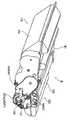
도 2는 본 발명의 실시예에 따른 카트리지의 사시도.
도 3은 본 발명의 실시예에 따른 카트리지의 사시도.
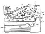
도 4는 본 발명의 실시예에 따른 장치 본체의 측단면도.
도 5는 본 발명의 실시예에 따른 드럼 플랜지(드럼축)의 사시도 및 종단면도.
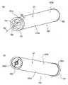
도 6은 본 발명의 실시예에 따른 감광 드럼의 사시도.
도 7은 본 발명의 실시예에 따른 감광 드럼의 종단면도.
도 8은 본 발명의 실시예에 따른 커플링의 사시도 및 종단면도.
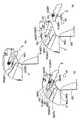
도 9는 본 발명의 실시예에 따른 드럼 베어링 부재의 사시도.
도 10은 본 발명의 실시예에 따른 카트리지의 측표면의 상세도.
도 11은 본 발명의 실시예에 따른 커플링 및 베어링 부재의 분해 사시도 및 종단면도.
도 12는 본 발명의 실시예에 따른 카트리지의 조립 후의 종단면도.
도 13은 본 발명의 실시예에 따른 카트리지의 조립 후의 종단면도.
도 14는 본 발명의 실시예에 따른 카트리지의 종단면도.
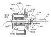
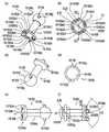
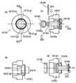
도 15는 드럼축 및 커플링의 조합된 상태를 도시하는 사시도.
도 16은 커플링의 경사진 상태를 도시하는 사시도.
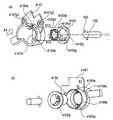
도 17은 본 발명의 실시예에 따른 장치 본체의 구동 구조의 사시도 및 종단면도.
도 18은 본 발명의 실시예에 따른 장치 본체의 카트리지 설치부의 사시도.
도 19는 본 발명의 실시예에 따른 장치 본체의 카트리지 설치부의 사시도.
도 20은 본 발명의 실시예에 따른 장치 본체에 대한 카트리지의 장착 과정을 도시하는 단면도.
도 21은 본 발명의 실시예에 따른 구동축과 커플링 사이의 결합 과정을 도시하는 사시도.
도 22는 본 발명의 실시예에 따른 구동축과 커플링 사이의 결합 과정을 도시하는 사시도.
도 23은 본 발명의 실시예에 따른 장치 본체의 결합 및 카트리지의 결합을 도시하는 사시도.
도 24는 본 발명의 실시예에 따른 구동축, 구동 기어, 커플링, 및 드럼축을 도시하는 분해 사시도.
도 25는 본 발명의 실시예에 따른 구동축으로부터 커플링의 분리 과정을 도시하는 사시도.
도 26은 본 발명의 실시예에 따른 커플링 및 드럼축을 도시하는 사시도.
도 27은 본 발명의 실시예에 따른 드럼축을 도시하는 사시도.
도 28은 본 발명의 실시예에 따른 구동축 및 구동 기어를 도시하는 사시도.
도 29는 본 발명의 실시예에 따른 커플링을 도시하는 사시도 및 측면도.
도 30은 본 발명의 실시예에 따른 드럼축, 구동축, 및 커플링을 도시하는 분해 사시도.
도 31은 본 발명의 실시예에 따른 카트리지의 측표면의 측면도 및 종단면도.
도 32는 본 발명의 실시예에 따른 장치 본체의 카트리지 설치부의 사시도 및 장치로부터 본 도면.
도 33은 본 발명의 실시예에 따른 카트리지의 장치 본체로부터의 탈착 과정을 도시하는 종단면도.
도 34는 본 발명의 실시예에 따른 카트리지의 장치 본체에 대한 장착 과정을 도시하는 종단면도.
도 35는 본 발명의 제2 실시예에 따른 구동축을 위한 위상 제어 수단을 도시하는 사시도.
도 36은 본 발명의 실시예에 따른 카트리지의 장착 과정을 도시하는 사시도.
도 37은 본 발명의 실시예에 따른 커플링의 사시도.
도 38은 본 발명의 실시예에 따른 장착 방향에서 본 카트리지의 장착 상태의 평면도.
도 39는 본 발명의 실시예에 따른 프로세스 카트리지(감광 드럼)의 구동 정지 상태를 도시하는 사시도.
도 40은 본 발명의 실시예에 따른 프로세스 카트리지의 탈착 작동을 도시하는 종단면도 및 사시도.
도 41은 본 발명의 제3 실시예에 따른 장치 본체 내에 제공된 도어가 개방된 상태를 도시하는 단면도.
도 42는 본 발명의 실시예에 따른 장치 본체의 구동측의 장착 가이드를 도시하는 사시도.
도 43은 본 발명의 실시예에 따른 카트리지의 구동측의 측면도.
도 44는 본 발명의 실시예에 따른 카트리지의 구동측으로부터 본 사시도.
도 45는 본 발명의 실시예에 따른 장치 본체에 대한 카트리지의 삽입 상태를 도시하는 측면도.
도 46은 본 발명의 제4 실시예에 따른 드럼 베어링 부재에 대한 걸림 부재의 부착 상태를 도시하는 사시도.
도 47은 본 발명의 실시예에 따른 드럼 베어링 부재, 커플링, 및 드럼축을 도시하는 분해 사시도.
도 48은 본 발명의 실시예에 따른 카트리지의 구동측을 도시하는 사시도.
도 49는 본 발명의 실시예에 따른 구동축과 커플링 사이의 결합 상태를 도시하는 사시도 및 종단면도.
도 50은 본 발명의 제5 실시예에 따른, 가압 부재가 드럼 베어링 부재에 장착된 상태를 도시하는 분해 사시도.
도 51은 본 발명의 실시예에 따른 드럼 베어링 부재, 커플링, 및 드럼축을 도시하는 분해 사시도.
도 52는 본 발명의 실시예에 따른 카트리지의 구동측을 도시하는 사시도.
도 53은 본 발명의 실시예에 따른 구동축과 커플링 사이의 결합 상태를 도시하는 사시도 및 종단면도.
도 54는 본 발명의 제6 실시예에 따른 주요 부재들을 조립하기 전의 카트리지를 도시하는 분해 사시도.
도 55는 본 발명의 실시예에 따른 구동측을 도시하는 측면도.
도 56은 본 발명의 실시예에 따른 드럼축 및 커플링의 개략적인 종단면도.
도 57은 본 발명의 실시예에 따른 구동축과 커플링 사이의 결합을 도시하는 종단면도.
도 58은 본 발명의 실시예에 따른 커플링 걸림 부재의 변형예를 도시하는 단면도.
도 59는 본 발명의 제7 실시예에 따른 드럼 베어링 부재에 대한 자석 부재의 부착 상태를 도시하는 사시도.
도 60은 본 발명의 실시예에 따른 드럼 베어링 부재, 커플링, 및 드럼축을 도시하는 분해 사시도.
도 61은 본 발명의 실시예에 따른 카트리지의 구동측을 도시하는 사시도.
도 62는 본 발명의 실시예에 따른 구동축과 커플링 사이의 결합 상태를 도시하는 사시도 및 종단면도.
도 63은 본 발명의 제8 실시예에 따른 카트리지의 구동측을 도시하는 사시도.
도 64는 본 발명의 실시예에 따른 베어링 부재의 조립 전의 상태를 도시하는 분해 사시도.
도 65는 본 발명의 실시예에 따른 드럼축, 커플링, 및 베어링 부재의 구조를 도시하는 종단면도.
도 66은 본 발명의 실시예에 따른 장치 본체 가이드의 구동측을 도시하는 사시도.
도 67은 본 발명의 실시예에 따른 걸림 부재의 분리 상태를 도시하는 종단면도.
도 68은 본 발명의 실시예에 따른 구동축과 커플링 사이의 결합을 도시하는 종단면도.
도 69는 본 발명의 제9 실시예에 따른 카트리지의 구동측을 도시하는 측면도.
도 70은 본 발명의 실시예에 따른 장치 본체 가이드의 구동측을 도시하는 사시도.
도 71은 본 발명의 실시예에 따른 카트리지와 본체 가이드 사이의 관계를 도시하는 측면도.
도 72는 본 발명의 실시예에 따른 본체 가이드와 커플링 사이의 관계를 도시하는 사시도.
도 73은 본 발명의 실시예에 따른, 카트리지의 본체에 대한 장착 과정을 도시하는, 구동측으로부터 본 측면도.
도 74는 본 발명의 제10 실시예에 따른 본체 가이드의 구동측을 도시하는 사시도.
도 75는 본 발명의 실시예에 따른 본체 가이드와 커플링 사이의 관계를 도시하는 측면도.
도 76은 본 발명의 실시예에 따른 본체 가이드와 커플링 사이의 관계를 도시하는 사시도.
도 77은 본 발명의 실시예에 따른 카트리지와 본체 가이드 사이의 관계를 도시하는 측면도.
도 78은 본 발명의 실시예에 따른 본체 가이드와 커플링 사이의 관계를 도시하는 사시도.
도 79는 본 발명의 실시예에 따른 본체 가이드와 커플링 사이의 관계를 도시하는 측면도.
도 80은 본 발명의 실시예에 따른 본체 가이드와 커플링 사이의 관계를 도시하는 사시도.
도 81은 본 발명의 실시예에 따른 본체 가이드와 커플링 사이의 관계를 도시하는 측면도.
도 82는 본 발명의 제11 실시예에 따른 커플링의 사시도 및 단면도.
도 83은 본 발명의 실시예에 따른 커플링의 사시도 및 단면도.
도 84는 본 발명의 실시예에 따른 커플링의 사시도 및 단면도.
도 85는 본 발명의 제12 실시예에 따른 커플링의 사시도 및 단면도.
도 86은 본 발명의 제13 실시예에 따른 커플링을 도시하는 사시도.
도 87은 본 발명의 실시예에 따른 드럼축, 구동축, 커플링, 및 가압 부재를 도시하는 단면도.
도 88은 본 발명의 실시예에 따른 드럼축, 커플링, 베어링 부재, 및 구동축을 도시하는 단면도.
도 89는 본 발명의 제14 실시예에 따른 드럼축 및 커플링을 도시하는 사시도.
도 90은 본 발명의 실시예에 따른 구동축과 커플링 사이의 결합 과정을 도시하는 사시도.
도 91은 본 발명의 제15 실시예에 따른 드럼축, 커플링, 및 베어링 부재를 도시하는 사시도 및 단면도.
도 92는 본 발명의 제16 실시예에 따른 커플링에 대한 지지 방법(장착 방법)을 도시하는 사시도.
도 93은 본 발명의 제17 실시예의 커플링에 대한 지지 방법(장착 방법)을 도시하는 사시도.
도 94는 본 발명의 일 실시예에 따른 카트리지의 사시도.
도 95는 본 발명의 실시예에 따른 커플링만을 도시하는 도면.
도 96은 본 발명의 일 실시예에 따른 커플링을 갖는 드럼 플랜지를 도시하는 도면.
도 97은 도 84의 S22-S22를 따라 취한 단면도.
도 98은 본 발명의 일 실시예에 따른 감광 드럼 유닛의 단면도.
도 99는 도 85의 S23-S23을 따라 취한 단면도.
도 100은 본 발명의 일 실시예에 따른 드럼축 및 커플링의 조합된 상태를 도시하는 사시도.
도 101은 본 발명의 일 실시예에 따른 커플링의 경사진 상태를 도시하는 사시도.
도 102는 본 발명의 일 실시예에 따른 구동축과 커플링 사이의 결합 과정을 도시하는 사시도.
도 103은 본 발명의 일 실시예에 따른 구동축과 커플링 사이의 결합 과정을 도시하는 사시도.
도 104는 본 발명의 일 실시예에 따른 구동축, 구동 기어, 커플링, 및 드럼축을 도시하는 분해 사시도.
도 105는 본 발명의 일 실시예에 따른 구동축으로부터 커플링의 분리 과정을 도시하는 사시도.
도 106은 본 발명의 일 실시예에 따른 드럼축과 커플링 사이의 조합된 상태를 도시하는 사시도.
도 107은 본 발명의 일 실시예에 따른 드럼축과 커플링 사이의 조합된 상태를 도시하는 사시도.
도 108은 본 발명의 일 실시예에 따른 드럼축과 커플링 사이의 조합된 상태를 도시하는 사시도.
도 109는 본 발명의 일 실시예에 따른, 구동측으로부터 본 감광 드럼을 갖는 제1 프레임 유닛의 사시도.
도 110은 본 발명의 일 실시예에 따른 드럼축 및 커플링을 도시하는 사시도.
도 111은 도 79의 S20-S20을 따라 취한 단면도.
도 112는 본 발명의 일 실시예에 따른 감광 드럼 유닛의 사시도.1 is a side cross-sectional view of a cartridge according to an embodiment of the present invention;
2 is a perspective view of a cartridge according to an embodiment of the present invention;
3 is a perspective view of a cartridge according to an embodiment of the present invention;
4 is a side cross-sectional view of an apparatus body according to an embodiment of the present invention.
5 is a perspective view and a longitudinal sectional view of a drum flange (drum shaft) according to an embodiment of the present invention.
6 is a perspective view of a photosensitive drum according to an embodiment of the present invention.
7 is a longitudinal sectional view of a photosensitive drum according to an embodiment of the present invention.
8 is a perspective view and a longitudinal section of a coupling according to an embodiment of the present invention.
9 is a perspective view of a drum bearing member according to an embodiment of the present invention.
10 is a detailed view of a side surface of a cartridge according to an embodiment of the present invention.
11 is an exploded perspective view and a longitudinal sectional view of a coupling and a bearing member according to an embodiment of the present invention.
12 is a longitudinal sectional view of the cartridge after assembly according to the embodiment of the present invention.
13 is a longitudinal sectional view of the cartridge after assembly according to the embodiment of the present invention.
14 is a longitudinal sectional view of a cartridge according to an embodiment of the present invention.
15 is a perspective view showing a combined state of the drum shaft and the coupling;
16 is a perspective view showing an inclined state of the coupling;
17 is a perspective view and a longitudinal cross-sectional view of a driving structure of an apparatus main body according to an embodiment of the present invention.
18 is a perspective view of a cartridge mounting portion of the apparatus main body according to the embodiment of the present invention.
19 is a perspective view of a cartridge mounting portion of the apparatus main body according to the embodiment of the present invention.
20 is a cross-sectional view showing the mounting process of the cartridge with respect to the apparatus main body according to the embodiment of the present invention.
FIG. 21 is a perspective view showing a coupling process between a drive shaft and a coupling according to an embodiment of the present invention; FIG.
22 is a perspective view showing a coupling process between a drive shaft and a coupling according to an embodiment of the present invention;
23 is a perspective view showing a combination of a main assembly of the apparatus and a cartridge according to an embodiment of the present invention.
24 is an exploded perspective view showing a drive shaft, a drive gear, a coupling, and a drum shaft according to an embodiment of the present invention.
25 is a perspective view illustrating a process of separating a coupling from a drive shaft according to an embodiment of the present invention;
26 is a perspective view showing a coupling and a drum shaft according to an embodiment of the present invention;
27 is a perspective view showing a drum shaft according to an embodiment of the present invention;
28 is a perspective view showing a drive shaft and a drive gear according to an embodiment of the present invention;
29 is a perspective view and a side view showing a coupling according to an embodiment of the present invention;
30 is an exploded perspective view showing a drum shaft, a drive shaft, and a coupling according to an embodiment of the present invention;
31 is a side view and a longitudinal section of a side surface of a cartridge according to an embodiment of the present invention;
32 is a perspective view and a view of the cartridge mounting portion of the apparatus main body according to the embodiment of the present invention.
33 is a longitudinal sectional view showing a process of detaching and attaching the cartridge from the apparatus main body according to the embodiment of the present invention.
34 is a longitudinal sectional view showing a process of mounting the cartridge to the main assembly of the apparatus according to the embodiment of the present invention.
35 is a perspective view showing a phase control means for a drive shaft according to a second embodiment of the present invention;
36 is a perspective view showing a mounting process of the cartridge according to the embodiment of the present invention;
37 is a perspective view of a coupling according to an embodiment of the present invention.
38 is a plan view of the cartridge in a mounted state in the mounting direction according to the embodiment of the present invention;
39 is a perspective view showing a driving stop state of the process cartridge (photosensitive drum) according to the embodiment of the present invention;
40 is a longitudinal sectional view and a perspective view showing a detachment operation of the process cartridge according to the embodiment of the present invention;
41 is a sectional view showing a state in which a door provided in the apparatus main body according to the third embodiment of the present invention is open;
42 is a perspective view showing a mounting guide on the drive side of the apparatus main body according to the embodiment of the present invention;
Fig. 43 is a side view of a driving side of a cartridge according to an embodiment of the present invention; Fig.
44 is a perspective view of a cartridge according to an embodiment of the present invention as seen from a drive side;
45 is a side view showing the insertion state of the cartridge with respect to the apparatus main body according to the embodiment of the present invention.
46 is a perspective view showing an attachment state of the engaging member to the drum bearing member according to the fourth embodiment of the present invention;
47 is an exploded perspective view showing a drum bearing member, a coupling, and a drum shaft according to an embodiment of the present invention;
48 is a perspective view showing the driving side of the cartridge according to the embodiment of the present invention;
49 is a perspective view and a longitudinal sectional view showing a coupling state between a drive shaft and a coupling according to an embodiment of the present invention;
50 is an exploded perspective view showing a state in which the pressing member is mounted on the drum bearing member, according to the fifth embodiment of the present invention;
51 is an exploded perspective view showing the drum bearing member, the coupling, and the drum shaft according to the embodiment of the present invention.
52 is a perspective view showing the driving side of the cartridge according to the embodiment of the present invention;
53 is a perspective view and a longitudinal sectional view showing a coupling state between a drive shaft and a coupling according to an embodiment of the present invention;
54 is an exploded perspective view showing the cartridge before assembling the main members according to the sixth embodiment of the present invention;
55 is a side view showing a driving side according to an embodiment of the present invention;
Figure 56 is a schematic vertical cross-sectional view of a drum shaft and coupling according to an embodiment of the present invention;
57 is a longitudinal sectional view showing a coupling between a drive shaft and a coupling according to an embodiment of the present invention;
58 is a sectional view showing a modified example of the coupling engagement member according to the embodiment of the present invention;
59 is a perspective view showing an attachment state of a magnet member to a drum bearing member according to a seventh embodiment of the present invention;
60 is an exploded perspective view showing the drum bearing member, the coupling, and the drum shaft according to the embodiment of the present invention.
61 is a perspective view showing the driving side of the cartridge according to the embodiment of the present invention;
62 is a perspective view and a longitudinal sectional view showing a coupling state between a drive shaft and a coupling according to an embodiment of the present invention;
63 is a perspective view showing the driving side of the cartridge according to the eighth embodiment of the present invention;
64 is an exploded perspective view showing a state before assembly of the bearing member according to the embodiment of the present invention;
65 is a longitudinal sectional view showing a structure of a drum shaft, a coupling, and a bearing member according to an embodiment of the present invention;
66 is a perspective view showing the driving side of the apparatus main assembly guide according to the embodiment of the present invention;
67 is a longitudinal sectional view showing a detached state of the engaging member according to the embodiment of the present invention.
68 is a longitudinal sectional view showing the coupling between the drive shaft and the coupling according to the embodiment of the present invention;
69 is a side view showing the drive side of the cartridge according to the ninth embodiment of the present invention;
70 is a perspective view showing a driving side of the apparatus body guide according to the embodiment of the present invention;
71 is a side view showing the relationship between the cartridge and the main assembly guide according to the embodiment of the present invention;
72 is a perspective view showing the relationship between the main body guide and the coupling according to the embodiment of the present invention;
73 is a side view of the cartridge viewed from the drive side, showing the mounting process for the main assembly of the cartridge, according to the embodiment of the present invention.
74 is a perspective view showing a drive side of a main body guide according to a tenth embodiment of the present invention;
75 is a side view showing a relationship between a main body guide and a coupling according to an embodiment of the present invention;
76 is a perspective view showing the relationship between the main body guide and the coupling according to the embodiment of the present invention;
77 is a side view showing the relationship between the cartridge and the main assembly guide according to the embodiment of the present invention;
78 is a perspective view showing a relationship between a body guide and a coupling according to an embodiment of the present invention;
79 is a side view showing the relationship between the main body guide and the coupling according to the embodiment of the present invention;
80 is a perspective view showing a relationship between a main body guide and a coupling according to an embodiment of the present invention;
81 is a side view showing the relationship between the main body guide and the coupling according to the embodiment of the present invention;
82 is a perspective view and a cross-sectional view of a coupling according to an eleventh embodiment of the present invention;
83 is a perspective view and a cross-sectional view of a coupling according to an embodiment of the present invention;
84 is a perspective view and a cross-sectional view of a coupling according to an embodiment of the present invention;
85 is a perspective view and a cross-sectional view of a coupling according to a twelfth embodiment of the present invention;
86 is a perspective view showing a coupling according to a thirteenth embodiment of the present invention;
FIG. 87 is a sectional view showing a drum shaft, a drive shaft, a coupling, and a pressing member according to an embodiment of the present invention; FIG.
88 is a sectional view showing a drum shaft, a coupling, a bearing member, and a drive shaft according to an embodiment of the present invention;
FIG. 89 is a perspective view showing a drum shaft and coupling according to a fourteenth embodiment of the present invention; FIG.
90 is a perspective view showing a coupling process between a drive shaft and a coupling according to an embodiment of the present invention;
91 is a perspective view and a sectional view showing a drum shaft, a coupling, and a bearing member according to a fifteenth embodiment of the present invention;
92 is a perspective view showing a supporting method (mounting method) for a coupling according to a sixteenth embodiment of the present invention;
93 is a perspective view showing a supporting method (mounting method) for a coupling according to a seventeenth embodiment of the present invention;
94 is a perspective view of a cartridge according to an embodiment of the present invention;
95 is a view showing only a coupling according to an embodiment of the present invention;
96 is a view of a drum flange having a coupling according to one embodiment of the present invention.
FIG. 97 is a sectional view taken along S22-S22 of FIG. 84; FIG.
98 is a sectional view of a photosensitive drum unit according to an embodiment of the present invention;
FIG. 99 is a sectional view taken along line S23-S23 of FIG. 85;
FIG. 100 is a perspective view showing a combined state of a drum shaft and a coupling according to an embodiment of the present invention; FIG.
101 is a perspective view showing an inclined state of a coupling according to an embodiment of the present invention;
FIG. 102 is a perspective view showing a coupling process between a drive shaft and a coupling according to an embodiment of the present invention; FIG.
103 is a perspective view showing a coupling process between a driving shaft and a coupling according to an embodiment of the present invention;
104 is an exploded perspective view showing a drive shaft, a drive gear, a coupling, and a drum shaft according to an embodiment of the present invention;
105 is a perspective view illustrating a process of separating a coupling from a drive shaft according to an embodiment of the present invention;
106 is a perspective view showing a combined state between a drum shaft and a coupling according to an embodiment of the present invention;
107 is a perspective view showing a combined state between a drum shaft and a coupling according to an embodiment of the present invention;
108 is a perspective view showing a combined state between a drum shaft and a coupling according to an embodiment of the present invention;
109 is a perspective view of a first frame unit having a photosensitive drum viewed from the drive side, according to an embodiment of the present invention;
110 is a perspective view showing a drum shaft and coupling according to one embodiment of the present invention;
FIG. 111 is a sectional view taken along line S20-S20 in FIG. 79; FIG.
112 is a perspective view of a photosensitive drum unit according to an embodiment of the present invention;
본 발명의 일 실시예에 따른 프로세스 카트리지 및 전자 사진 화상 형성 장치가 설명될 것이다.A process cartridge and an electrophotographic image forming apparatus according to an embodiment of the present invention will be described.
[실시예 1][Example 1]
(1) 프로세스 카트리지의 간단한 설명(1) A brief description of the process cartridge
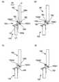
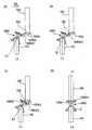
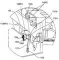
본 발명의 실시예가 적용된 프로세스 카트리지(B)가 도 1 내지 4를 참조하여 설명될 것이다. 도 1은 카트리지(B)의 단면도이다. 도 2 및 3은 카트리지(B)의 사시도이다. 도 4는 전자 사진 화상 형성 장치 본체(A: 이하에서, "장치 본체(A)"로 불림)의 단면도이다. 장치 본체(A)는 카트리지(B)가 제외된 전자 사진 화상 형성 장치의 부분에 대응한다.A process cartridge B to which an embodiment of the present invention is applied will be described with reference to Figs. Fig. 1 is a sectional view of the cartridge B. Fig. Figs. 2 and 3 are perspective views of the cartridge B. Fig. 4 is a sectional view of an electrophotographic image forming apparatus main body A (hereinafter referred to as "apparatus main body A"). The apparatus main body A corresponds to the portion of the electrophotographic image forming apparatus in which the cartridge B is excluded.
도 1 내지 3을 참조하면, 카트리지(B)는 전자 사진 감광 드럼(107)을 포함한다. 감광 드럼(107)은 도 4에 도시된 바와 같이, 카트리지(B)가 장치 본체(A) 내에 장착될 때 커플링 메커니즘에 의해 장치 본체(A)로부터 회전력을 수용함으로써 회전된다. 카트리지(B)는 사용자에 의해 장치 본체(A)에 장착되고 그로부터 탈착될 수 있다.Referring to Figs. 1 to 3, the cartridge B includes an electrophotographic
대전 롤러(108)가 대전 수단(프로세스 수단)으로서 감광 드럼(107)의 외주면과 접촉하여 제공된다. 대전 롤러(108)는 장치 본체(A)로부터의 전압 인가에 의해 감광 드럼(107)을 전기적으로 대전시킨다. 대전 롤러(108)는 감광 드럼(107)의 회전에 의해 회전된다.The charging
카트리지(B)는 현상 수단(프로세스 수단)으로서 현상 롤러(110)를 포함한다. 현상 롤러(110)는 감광 드럼(107)의 현상 영역에 현상제를 공급한다. 현상 롤러(110)는 감광 드럼(107) 상에 형성된 정전 잠상을 현상제(t)로 현상한다. 현상 롤러(110)는 자석 롤러(111: 고정 자석)를 내부에 포함한다. 현상 롤러(110)의 주연면과 접촉하여, 현상 블레이드(112)가 제공된다. 현상 블레이드(112)는 현상 롤러(110)의 주연면 상에 적층되는 현상제(t)의 양을 한정한다. 현상 블레이드(112)는 현상제(t)에 마찰 전하를 부여한다.The cartridge B includes the developing
현상제 수용 용기(114) 내에 담긴 현상제(t)는 교반 부재(115, 116)의 회전에 의해 현상 챔버(113a)로 보내지며, 전압을 공급받은 현상 롤러(110)가 회전된다. 결과적으로, 현상 블레이드(112)에 의해 전하가 부여되어 있는 현상제 층이 현상 롤러(110)의 표면 상에 형성된다. 현상제(t)는 잠상에 따라 감광 드럼(107) 상으로 전사된다. 결과적으로, 잠상이 현상된다.The developer t contained in the
감광 드럼(107) 상에 형성된 현상제는 전사 롤러(104)에 의해 기록 매체(102) 상으로 전사된다. 기록 매체(102)는 현상제의 화상을 그 위에 형성하기 위해 사용되고, 예컨대 기록 용지, 라벨, OHP 시트 등이다.The developer formed on the
감광 드럼(107)의 외주면과 접촉하여, 탄성 세척 블레이드(117a)가 세척 수단(프로세스 수단)으로서 배치된다. 세척 블레이드(117a)는 단부에서 감광 드럼(107)과 탄성적으로 접촉하고, 현상제 화상이 기록 매체(102) 상으로 전사된 후에 감광 드럼(102) 상에 잔류하는 현상제(t)를 제거한다. 세척 블레이드(117a)에 의해 감광 드럼(107)의 표면으로부터 제거된 현상제(t)는 제거된 현상제 저장소(117b) 내에 수용된다.The
카트리지(B)는 제1 프레임 유닛(119) 및 제2 프레임 유닛(120)에 의해 일체로 구성된다.The cartridge B is integrally constituted by the
제1 프레임 유닛(119)은 카트리지 프레임(B1)의 일부로서 제1 프레임(113)에 의해 구성된다. 제1 프레임 유닛(119)은 현상 롤러(110), 현상 블레이드(112), 현상 챔버(113a), 현상제 수용 용기(114), 및 교반 부재(115, 116)를 포함한다.The
제2 프레임 유닛(120)은 카트리지 프레임(B1)의 일부로서 제2 프레임(118)에 의해 구성된다. 제2 프레임 유닛(120)은 감광 드럼(107), 세척 블레이드(117a), 제거된 현상제 저장소(117b), 및 대전 롤러(108)를 포함한다.The
제1 프레임 유닛(119) 및 제2 프레임 유닛(120)은 핀(P)에 의해 서로 회전 가능하게 연결된다. 제1 및 제2 프레임 유닛(119, 120)들 사이에 제공된 탄성 부재(135: 도 3)에 의해, 현상 롤러(110)는 감광 드럼(107)에 대해 가압된다.The
사용자는 그립을 파지함으로써 장치 본체(A)의 카트리지 장착부(130a)에 카트리지(B)를 부착(장착)한다. 장착 중에, 후술할 바와 같이, 장치 본체(A)의 구동축(180: 도 17) 및 카트리지(B)의 회전력 절단 부품인 커플링 부재(150: 후술함)가 카트리지(B)의 장착 동작과 동기하여 서로 연결된다. 감광 드럼(107) 등은 장치 본체(A)로부터 회전력을 수용함으로써 회전된다.The user grips the grip to attach (mount) the cartridge B to the
(2) 전자 사진 화상 형성 장치의 설명(2) Description of electrophotographic image forming apparatus
도 4를 참조하여, 전술한 카트리지(B)를 사용하는 전자 사진 화상 형성 장치가 설명될 것이다.Referring to Fig. 4, an electrophotographic image forming apparatus using the above-described cartridge B will be described.
다음에서, 레이저 빔 프린터가 장치 본체(A)의 일례로서 설명될 것이다.In the following, a laser beam printer will be described as an example of the apparatus main body A.
화상 형성 중에, 회전 감광 드럼(107)의 표면은 대전 롤러(108)에 의해 균일하게 전기적으로 대전된다. 그 다음, 감광 드럼(107)의 표면은 화상 정보에 따라 레이저 다이오드, 다각형 거울, 렌즈, 및 반사 거울을 포함한 광학 수단(101)으로부터 방출되는 레이저 광으로 조사된다. 결과적으로, 감광 드럼(107) 상에, 화상 정보에 따른 정전 잠상이 형성된다. 잠상은 전술한 현상 롤러(110)에 의해 현상된다.During image formation, the surface of the rotating
다른 한편으로, 화상 정보와 동기하여, 카세트(103a) 내에 설치된 기록 매체(102)가 공급 롤러(103b) 및 이송 롤러 쌍(103c, 103d, 103e)에 의해 전사 위치로 이송된다. 전사 위치에, 전사 롤러(104)가 전사 수단으로서 배치된다. 전사 롤러(104)에 전압이 인가된다. 결과적으로, 감광 드럼(107) 상에 형성된 현상제 화상이 기록 매체(102) 상으로 전사된다.On the other hand, in synchronization with the image information, the
현상제 화상이 전사된 기록 매체(102)는 가이드(103f)를 통해 정착 수단(105)으로 이송된다. 정착 수단(105)은 구동 롤러(105c) 및 가열기(105a)를 내부에 포함하는 정착 롤러(105b)를 포함한다. 통과하는 기록 매체(102)에, 열 및 압력이 인가되어, 현상제 화상이 기록 매체(102) 상에 정착된다. 결과적으로, 기록 매체(102) 상에, 화상이 형성된다. 그 후에, 기록 매체(102)는 롤러 쌍(103g, 103h)에 의해 이송되어, 트레이(106) 상으로 토출된다. 전술한 롤러(103b), 이송 롤러 쌍(103c, 103d, 103e), 가이드(103f), 롤러 쌍(103g, 103h) 등은 기록 매체(102)를 이송하기 위한 이송 수단(103)을 구성한다.The
카트리지 장착부(130a)는 내부에 카트리지(B)를 장착하기 위한 부분(공간)이다. 카트리지(B)가 공간 내에 위치된 상태에서, 카트리지(B)의 커플링 부재(150: 후술함)는 장치 본체(A)의 구동축과 연결된다. 이러한 실시예에서, 장착부(130a)에 대한 카트리지(B)의 장착은 장치 본체(A)에 대한 카트리지(B)의 장착으로서 불린다. 아울러, 장착부(130b)로부터의 카트리지(B)의 탈착(제거)은 장치 본체(A)로부터의 카트리지(B)의 탈착으로서 불린다.The
(3) 드럼 플랜지의 구성에 대한 설명(3) Description of the configuration of the drum flange
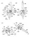
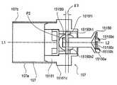
먼저, 회전력이 장치 본체(A)로부터 감광 드럼(107)에 전달되는 드럼 플랜지 측(이하에서, 단순히 "구동측"으로 불림)이 도 5를 참조하여 설명될 것이다. 도 5의 (a)는 구동측에서의 드럼 플랜지의 사시도이고, 도 5의 (b)는 도 5의 (a)에 도시된 S1-S1을 따라 취한 드럼 플랜지의 단면도이다. 추가로, 감광 드럼의 축선 방향에 대해, 구동측으로부터 대향한 측은 "비구동측"으로 불린다.First, the drum flange side (hereinafter, simply referred to as "drive side") where the rotational force is transmitted from the apparatus main body A to the
드럼 플랜지(151)는 사출 성형에 의해 수지 재료로 성형된다. 수지 재료의 예는 폴리아세탈, 폴리카보네이트 등을 포함할 수 있다. 드럼축(153)은 철, 스테인리스강 등과 같은 금속성 재료로 형성된다. 감광 드럼(107)을 회전시키기 위한 부하 토크에 따라 드럼 플랜지(151) 및 드럼축(153)에 대한 재료를 적절하게 선택하는 것이 가능하다. 예를 들어, 드럼 플랜지(151)가 금속성 재료로 형성될 수도 있고, 드럼축(153)이 수지 재료로 형성될 수도 있다. 드럼 플랜지(151) 및 드럼축(153)이 모두 수지 재료로 형성되면, 이들은 일체로 성형될 수 있다.The
플랜지(151)는 감광 드럼(107)의 내측 표면과 결합하는 결합부(151a), 현상 롤러(110)에 회전력을 전달하기 위한 기어부(헬리컬 기어 또는 스퍼 기어), 및 드럼 베어링 상에 회전 가능하게 지지되는 결합부(151d)를 구비한다. 더 구체적으로, 플랜지(151)에 관해, 결합부(151a)는 이하에서 설명될 바와 같이 원통형 드럼(107)의 일 단부와 결합한다. 이들은 감광 드럼(107)의 회전 축선(L1)과 동축으로 배치된다. 그리고, 드럼 결합부(151a)는 원통 형상을 갖고, 이와 직교하는 기부(151b)가 제공된다. 기부(151b)는 축선(L1)의 방향에 대해 외측으로 돌출되는 드럼축(153)을 구비한다. 이러한 드럼축(153)은 드럼 결합부(151a)과 동축이다. 이들은 회전 축선(L1)과 동축이 되도록 고정된다. 이들의 고정 방법에 관해, 억지 끼워 맞춤, 본딩, 삽입 성형 등이 이용 가능하고, 적절하게 선택된다.The
드럼축(153)은 돌출 구성을 가지며, 감광 드럼(107)의 회전 축선과 동축이 되도록 배치되는 원통부(153a)를 포함한다. 드럼축(153)은 감광 드럼(107)의 축선(L1) 상에서 감광 드럼(107)의 단부 상에 제공된다. 또한, 드럼축(153)은 재료, 부하, 및 공간을 고려하여 약 5 - 15 mm 직경이다. 원형 칼럼 부분(153a)의 자유 단부(153b)는 반구면 구성을 가져서, 이하에서 상세하게 설명될 바와 같이, 회전력 전달부인 드럼 커플링 부재(150)의 축선이 경사질 때 원활하게 경사질 수 있다. 또한, 드럼 커플링 부재(150)로부터 회전력을 수용하기 위해, 회전력 전달 핀(155: 회전력 수용 부재(부분))이 드럼축(153)의 자유 단부의 감광 드럼(107) 측에 제공된다. 핀(155)은 드럼축(153)의 축선과 사실상 직교하는 방향으로 연장된다.The
핀(155)은 회전력 수용 부재로서 드럼축(153)의 원형 칼럼 부분(153a)보다 더 작은 직경을 가지며 금속 또는 수지 재료로 만들어진 원통 형상을 갖는다. 그리고, 이는 억지 끼워 맞춤, 본딩 등에 의해 드럼축(153)에 고정된다. 그리고, 핀(155)은 축선이 감광 드럼(107)의 축선(L1)과 교차하는 방향으로 고정된다. 바람직하게는, 핀(155)의 축선을 드럼축(153)의 자유 단부(153b)의 구면의 중심(P2)을 통과하도록 배치하는 것이 바람직하다 (도 5의 (b)). 자유 단부(153b)가 실제로 반구면 구성이지만, 중심(P2)은 반구면이 일부를 이루는 가상 구면의 중심이다. 또한, 핀(155)의 개수는 적절하게 선택될 수 있다. 이러한 실시예에서, 단일 핀(155)이 조립 특성의 관점에서 그리고 구동 토크를 확실하게 전달하기 위해 사용된다. 핀(155)은 상기 중심(P2)을 통과하고, 드럼축(153)을 통과한다. 그리고, 핀(155)은 직경 방향으로 대향한 드럼축(153)의 주연면의 위치(155a1, 155a2)들에서 외측으로 돌출된다. 특히, 핀(155)은 2개의 대향 위치(155a1, 155a2)에서 드럼축(153)의 축선(축선(L1))과 직교하는 방향으로 돌출된다. 이에 의해, 드럼축(153)은 2개의 위치에서 드럼 커플링 부재(150)로부터 회전력을 수용한다. 이러한 실시예에서, 핀(155)은 드럼축(153)의 자유 단부로부터 5 mm의 범위 내에서 드럼축(153)에 장착된다. 그러나, 이는 본 발명을 제한하지 않는다.The
또한, 결합부(151d) 및 기부(151b)에 의해 형성된 공간부(151e)는 (후술할) 드럼 커플링 부재(150)를 플랜지(151)에 장착할 때, 드럼 커플링 부재(150)의 일부를 수납한다.The
이러한 실시예에서, 현상 롤러(110)에 회전력을 전달하기 위한 기어부(151c)는 플랜지(151)에 장착된다. 그러나, 현상 롤러(110)의 회전은 플랜지(151)를 통해 전달되지 않을 수 있다. 이러한 경우에, 기어부(151c)는 불필요하다. 그러나, 플랜지(151)에 기어부(151a)를 배치하는 경우에, 기어부(151a)의 플랜지(151)와의 일체 성형이 이용될 수 있다.In this embodiment, the
플랜지(151), 드럼축(153), 및 핀(155)은 이하에서 설명될 바와 같이 드럼 커플링 부재(150)로부터 회전력을 수용하는 회전력 수용 부재로서 기능한다.The
(4) 전자 사진 감광 부재 드럼 유닛의 구조(4) Structure of electrophotographic photosensitive member drum unit
도 6 및 도 7을 참조하여, 전자 사진 감광 부재 드럼 유닛(“드럼 유닛”)의 구조가 설명될 것이다.Referring to Figs. 6 and 7, the structure of the electrophotographic photosensitive member drum unit (" drum unit ") will be described.
도 6의 (a)는 드럼 유닛(U1)의 구동측으로부터 본 사시도이고, 도 6의 (b)는 비구동측으로부터 본 사시도이다. 또한 도 7은 도 6의 (a)의 S2-S2를 따라 취한 단면도이다.6 (a) is a perspective view of the drum unit U1 as seen from the driving side, and Fig. 6 (b) is a perspective view as seen from a non-driving side. 7 is a cross-sectional view taken along line S2-S2 of Fig. 6 (a).
감광 드럼(107)은 주연면 상에 감광층(107b)으로 코팅된 원통형 드럼(107a)을 갖는다.The
원통형 드럼(107a)은 알루미늄과 같은 전기 전도성 실린더, 및 그 위에 도포된 감광층(107b)을 갖는다. 대향 단부들은 드럼 표면 및 드럼 플랜지(151, 152)와 결합하기 위한 사실상 동축인 개구부(107a1, 107a2)들을 구비한다. 특히, 드럼축(153)은 원통형 드럼(107a)과 동축으로 원통형 드럼(107a)의 단부 상에 제공된다. 기어가 151c에 의해 표시되어 있고, 커플링(150)이 구동축(180)으로부터 수용된 회전력을 현상 롤러(110)에 전달한다. 기어(151c)는 플랜지(15)와 일체로 성형된다.The
실린더(107a)는 중공 또는 중실일 수 있다.The
구동측의 드럼 플랜지(151)에 관해, 이는 상기에서 설명되었으므로, 설명이 생략된다.Since the
비구동측의 드럼 플랜지(152)가 사출 성형에 의해 구동측과 유사하게 수지 재료로 만들어진다. 그리고, 드럼 결합부(152b) 및 베어링부(152a)는 서로 사실상 동축으로 배치된다. 또한, 플랜지(152)는 드럼 접지판(156)을 구비한다. 드럼 접지판(156)은 전기 전도성 박판(금속)이다. 드럼 접지판(156)은 전기 전도성 원통형 드럼(107a)의 내측 표면과 접촉하는 접촉부(156b1, 156b2) 및 (이하에서 설명될) 드럼 접지축(154)과 접촉하는 접촉부(156a)를 포함한다. 그리고, 감광 드럼(107)을 접지할 목적으로, 드럼 접지판(156)은 장치 본체(A)와 전기적으로 연결된다.The
드럼 접지판(156)이 플랜지(152) 내에 제공된다고 설명되었지만, 본 발명은 이러한 예로 제한되지 않는다. 예를 들어, 드럼 접지판(156)은 드럼 플랜지(151)에 배치될 수 있고, 접지부와 연결될 수 있는 위치를 적절하게 선택하는 것이 가능하다.Although the
따라서, 드럼 유닛(U1)은 실린더(107a), 플랜지(151), 드럼축(153), 핀(155), 및 드럼 접지판(156)을 갖는 감광 드럼(107)을 포함한다.The drum unit U1 includes the
(5) 회전력 전달부(드럼 커플링 부재)(5) Torque transmitting portion (drum coupling member)
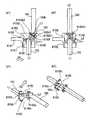
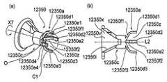
회전력 전달부인 드럼 커플링 부재의 일례에 대한 설명이 도 8을 참조하여 이루어질 것이다. 도 8의 (a)는 드럼 커플링 부재의 장치 본체측으로부터 본 사시도이고, 도 8의 (b)는 드럼 커플링 부재의 감광 드럼측으로부터 본 사시도이고, 도 8의 (c)는 커플링 회전 축선(L2) 방향과 직교하는 방향에서 본 도면이다. 또한, 도 8의 (d)는 드럼 커플링 부재의 장치 본체측으로부터 본 측면도이고, 도 8의 (e)는 감광 드럼측으로부터 본 도면이고, 도 8의 (f)는 도 8의 (d)의 S3를 따라 취한 단면도이다.A description will be given of an example of the drum coupling member which is a rotational force transmitting portion with reference to Fig. 8 (b) is a perspective view of the drum coupling member as seen from the side of the photosensitive drum, and FIG. 8 (c) is a perspective view of the coupling rotation And viewed in a direction orthogonal to the direction of the axis L2. 8 (d) is a side view of the drum coupling member viewed from the apparatus main body side, and FIG. 8 (e) is a view seen from the photosensitive drum side, and FIG. 8 (f) Sectional view taken along line S3 of FIG.
드럼 커플링 부재(150: "커플링")는 카트리지(B)가 장착부(설치 섹션)(130a)에 장착되어 설치되는 상태에서 장치 본체(A)의 구동축(180: 도 17)과 결합한다. 또한, 커플링(150)은 카트리지(B)가 장치 본체(A)로부터 취출될 때, 구동축(180)으로부터 분리된다. 그리고, 커플링(150)은 구동축(180)과 결합된 상태에서 장치 본체(A) 내에 제공된 모터로부터 구동축(180)을 통해 회전력을 수용한다. 또한, 커플링(150)은 회전력을 감광 드럼(107)에 전달한다. 커플링(150)에 대해 이용 가능한 재료는 폴리아세탈 및 폴리카보네이트 PPS와 같은 수지 재료이다. 그러나, 커플링(150)의 강성을 상승시키기 위해, 유리 섬유, 탄소 섬유 등이 요구되는 부하 토크에 대응하여 전술한 수지 재료 내에 혼합될 수 있다. 상기 재료를 혼합하는 경우에, 커플링(150)의 강성은 상승될 수 있다. 또한, 수지 재료 내에, 금속이 삽입될 수 있고, 강성은 추가로 상승될 수 있고, 전체 커플링은 금속 등으로부터 제조될 수 있다.The drum coupling member 150 ("coupling") engages with the driving shaft 180 (Fig. 17) of the apparatus main body A in a state in which the cartridge B is mounted on the mounting portion (installation section) 130a. Further, the
커플링(150)은 주로 3개의 부분을 포함한다.The
제1 부분은 (후술할) 구동축(180)과 결합할 수 있고, 구동축(180) 상에 제공된 회전력 인가 부분인 회전력 전달 핀(182: 본체측 회전력 전달부)으로부터 회전력을 수용하기 위한 커플링측 피구동부(150a)이다. 또한, 제2 부분은 핀(155)과 결합할 수 있고, 드럼축(153)에 회전력을 전달하기 위한 커플링측 구동부(150b)이다. 또한, 제3 부분은 피구동부(150a)와 구동부(150b)를 서로 연결하기 위한 연결부(150c)이다 (도 8의 (c) 및 (f)).The first portion is engageable with the drive shaft 180 (to be described later) and is provided with a coupling
피구동부(150a), 구동부(150b), 및 연결부(150c)는 서로 연결될 수 있다. 이러한 실시예에서, 이들은 수지 재료로 일체로 성형된다. 이에 의해, 커플링(150)의 제조는 간편하고, 부품으로 정확도가 높다. 도 8의 (f)에 도시된 바와 같이, 피구동부(150a)는 커플링(150)의 회전 축선(L2)을 향해 확대되는 구동축 삽입 개구부(150m)를 구비한다. 구동부(150b)는 회전 축선(L2)을 향해 확대되는 드럼축 삽입 개구부(150l)를 갖는다.The driven
개구부(150m)는 커플링(150)이 장치 본체(A)에 장착된 상태에서 구동축(180)을 향해 확대되는 확대부로서 원추형 구동축 수용면(150f)을 갖는다. 수용면(150f)은 도 8의 (f)에 도시된 바와 같이 오목부(150z)를 구성한다. 오목부(150z)는 축선(L2)의 방향에 대해 감광 드럼(107)에 인접한 측면과 대향한 위치에서 개구부(150m)를 포함한다.The
이에 의해, 카트리지(B) 내에서의 감광 드럼(107)의 회전 위상에 관계없이, 커플링(150)은 구동축(180)의 자유 단부에 의해 방해받지 않으면서, 감광 드럼(107)의 축선(L1)에 대한 회전력 전달 각도 위치, 결합전 각도 위치, 및 이탈 각도 위치 사이에서 피벗할 수 있다. 회전력 전달 각도 위치, 결합전 각도 위치, 및 이탈 각도 위치는 이하에서 설명될 것이다.Thereby, the
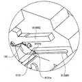
복수의 돌출부(150d1 - 150d4: 결합부)가 오목부(150z)의 단부 표면 상에서 축선(L2)에 대한 원주부 상에 등간격으로 제공된다. 인접한 돌출부(150d1, 150d2, 150d3, 150d4)들 사이에, 대기부(150k1, 150k2, 150k3, 150k4)가 제공된다. 인접한 돌출부(150d1 - 150d4)들 사이의 간격은 핀(182)의 외경보다 더 커서, 장치 본체(A) 내에 제공된 구동축(180)의 회전력 전달 핀(182: 회전력 인가부)이 수납된다. 인접한 돌출부들 사이의 오목부가 대기부(150k1 - k4)이다. 회전력이 구동축(180)으로부터 커플링(150)에 전달될 때, 전달 핀(182a1, 182a2)은 대기부(150k1 - k4)들 중 임의의 하나에 의해 수납된다. 또한, 도 8의 (d)에서, 커플링(150)의 회전 방향과 교차하는 회전력 수용면(150e: 회전력 수용부)(150e1 - e4)이 시계 방향(X1)으로 각각의 돌출부(150d)의 하류에 제공된다. 특히, 돌출부(150d1)는 수용면(150e1)을 갖고, 돌출부(150d2)는 수용면(150e2)을 갖고, 돌출부(150d3)는 수용면(150e3)을 갖고, 돌출부(150d4)는 수용면(150e4)을 갖는다. 구동축(180)이 회전하는 상태에서, 핀(182a1, 182a2)은 수용면(150e1 - 150e4)들 중 임의의 하나에 접촉한다. 이렇게 함으로써, 핀(182a1, 182a2)에 의해 접촉되는 수용면(150e)은 핀(182)에 의해 밀린다. 이에 의해, 커플링(150)은 축선(L2)에 대해 회전한다. 수용면(150e1 - 150e4)은 커플링(150)의 회전 방향과 교차하는 방향으로 연장된다.A plurality of protrusions 150d1 to 150d4 (coupling portions) are provided on the circumferential portion with respect to the axis L2 on the end surface of the
또한, 커플링(150)에 전달되는 회전 토크를 가능한 한 안정화하기 위해, 회전력 수용면(150e)은 축선(L2) 상에서 중심을 갖는 동일 원주부 상에 배치되는 것이 바람직하다. 이에 의해, 회전력 전달 반경이 일정하고, 커플링(150)에 전달되는 회전 토크가 안정화된다. 또한, 돌출부(150d1 - 150d4)에 관해, 커플링이 받는 힘의 균형에 의해, 커플링(150)의 위치가 안정화되는 것이 바람직하다. 이러한 이유로, 본 실시예에서, 수용면(150e)들이 직경 방향으로 대향한 위치(180°)에 배치된다. 특히, 본 실시예에서, 수용면(150e1)과 수용면(150e3)은 서로에 대해 직경 방향으로 대향되고, 수용면(150e2)과 면(150e4)은 서로에 대해 직경 방향으로 대향한다 (도8의 (d)). 이러한 배열에 의해, 커플링이 받는 힘은 힘 쌍을 구성한다. 그러므로, 커플링(150)은 힘 쌍을 수용함으로써만 회전 운동을 계속할 수 있다. 이러한 이유로, 커플링(150)은 회전 축선(L2)의 위치에 있어서 규정될 필요가 없이 회전될 수 있다. 또한, 개수에 관해, 구동축(180)의 핀(182)(회전력 인가부)이 대기부(150k1 - 150k2)로 진입할 수 있는 한, 적합하게 선택하는 것이 가능하다. 본 실시예에서, 도 8에 도시된 바와 같이, 4개의 수용면이 제공된다. 본 실시예는 이러한 예로 제한되지 않는다. 예를 들어, 수용면(150e: 돌출부(150d1 - 150d4))은 동일 원주부(가상원(C1), 도 8의 (d)) 상에 배치될 필요가 없다. 또는, 직경 방향으로 대향하는 위치들에 배치할 필요도 없다. 그러나, 수용면(150e)을 전술한 바와 같이 배치함으로써 전술한 효과가 제공될 수 있다.In order to stabilize the rotational torque transmitted to the
여기서, 본 실시예에서, 핀의 직경은 대략 2 mm이고, 대기부(150k)의 원주방향 길이는 대략 8 mm이다. 대기부(150k)의 원주방향 길이는 (가상원 상의) 인접한 돌출부(150d)들 사이의 간격이다. 치수는 본 발명에 대해 제한적이지 않다.Here, in this embodiment, the diameter of the fin is approximately 2 mm, and the circumferential length of the
개구부(150m)와 유사하게, 드럼축 삽입 개구부(150l)는 카트리지(B)에 장착된 상태에서, 드럼축(153)측을 향해서 확대되는 확대부의 원추형 회전력 수용면(150i)을 갖는다. 수용면(150i)은 도8의 (f)에 도시된 바와 같이, 오목부(150q)를 구성한다.Similar to the
이에 의해, 카트리지(B) 내에서의 감광 드럼(107)의 회전 위상에 관계없이, 커플링(150)은 드럼축(153)의 자유 단부에 의해 방해받지 않으면서, 회전력 전달 각도 위치, 결합전 각도 위치, 및 이탈 각도 위치 사이에서 피벗할 수 있다. 오목부(150q)는 도시된 예에서, 축선(L2) 상에서 중심을 갖는 원추형 수용면(150i)에 의해 구성된다. 대기 개구부(150g1 또는 150g2: "개구부")가 수용면(150i) 내에 제공된다 (도 8의 (b)). 커플링(150)에 관해서는 커플링(150)이 드럼축(153)에 장착될 수 있도록 핀(155)이 이러한 개구부(150g1 또는 150g2)의 내부로 삽입될 수 있다. 그리고, 개구부(150g1 또는 150g2)의 크기는 핀(155)의 외경보다 더 크다. 이렇게 함으로써, 카트리지(B) 내에서의 감광 드럼(107)의 회전 위상에 관계없이, 커플링(150)은 핀(155)에 의해 방해받지 않으면서 후술하는 회전력 전달 각도 위치 및 결합전 각도 위치 (또는 이탈 각도 위치) 사이에서 피벗 가능하다.Thus, the
특히, 돌출부(150d)는 오목부(150z)의 자유 단부에 인접하게 제공된다. 그리고, 돌출부(150d)는 커플링(150)이 회전하는 회전 방향과 교차하는 교차 방향으로서 돌출하여, 회전 방향을 따라 간격을 두고 제공된다. 그리고, 카트리지(B)가 장치 본체(A)에 장착된 상태에서, 수용면(150e)은 핀(182)에 결합하거나 그에 맞닿고, 핀(182)에 의해 밀린다.In particular, the
이에 의해, 수용면(150e)은 구동축(180)으로부터의 회전력을 수용한다. 또한, 수용면(150e)들은 축선(L2)으로부터 등거리에 배치되고, 축선(L2)을 사이에 두고 한 쌍을 구성하며, 돌출부(150d)의 교차 방향으로의 표면에 의해 구성된다. 또한, 대기부(150k: 오목부)는 회전 방향을 따라 제공되고, 축선(L2)의 방향으로 만입된다.Thus, the receiving
대기부(150k)는 인접한 돌출부(150d)들 사이의 공간으로서 형성된다. 카트리지(B)가 장치 본체(A)에 장착된 상태에서, 핀(182)이 대기부(150k)에 진입하여, 구동되기를 대기한다. 그리고, 구동축(180)이 회전하면, 핀(182)은 수용면(150e)을 가압한다.The
이에 의해, 커플링(150)이 회전한다.Thereby, the
회전력 수용면(150e: 회전력 수용 부재(수용부))은 구동축 수용면(150f)의 내부 배치될 수 있다. 또는, 수용면(150e)은 축선(L2)의 방향에 대해 수용면(150f)으로부터 외측으로 돌출한 부분 내에 제공될 수 있다. 수용면(150e)이 수용면(150f)의 내부에 배치되면, 대기부(150k)는 수용면(150f)의 내부에 배치된다.The rotational
특히, 대기부(150k)는 수용면(150f)의 원호부의 내부에서 돌출부(150d)들 사이에 제공된 오목부이다. 또한, 수용면(150e)이 외측으로 돌출한 위치에 배치되면, 대기부(150k)는 돌출부(150d) 사이에 위치되는 오목부이다. 여기서, 오목부는 축선(L2)의 방향으로 연장되는 관통 구멍일 수 있거나, 일 단부에서 폐쇄될 수 있다. 특히, 오목부는 돌출부(150d)들 사이에 제공된 공간 영역에 의해 제공된다. 그리고, 카트리지(B)가 장치 본체(A)에 장착된 상태에서, 핀(182)을 상기 영역 내로 진입시킬 수 있기만 하면 된다.In particular, the
대기부의 이러한 구조는 후술하는 실시예에 대해 유사하게 적용된다.This structure of the waiting section is similarly applied to the embodiments described later.
도 8의 (e)에서, 회전력 전달면(150h(150h1 또는 150h2): 회전력 전달부)이 시계 방향(X1)으로 개구부(150g1 또는 150g2)의 상류에 제공된다. 그리고, 회전력은 핀(155a1, 155a2)들 중 임의의 하나에 접촉하는 전달부(150h1 또는 150h2)에 의해 커플링(150)으로부터 감광 드럼(107)에 전달된다. 특히, 전달면(150h1 또는 150h2)이 핀(155)의 측면을 민다. 이에 의해, 커플링(150)은 중심이 축선(L2)과 정렬된 채로 회전한다. 전달면(150h1 또는 150h2)은 커플링(150)의 회전 방향과 교차하는 방향으로 연장된다.8E, a rotational force transmitting surface 150h (150h1 or 150h2: rotational force transmitting portion) is provided in the clockwise direction X1 upstream of the opening 150g1 or 150g2. The rotational force is transmitted from the
돌출부(150d)와 유사하게, 전달면(150h1 또는 150h2)들을 동일 원주부 상에서 서로에 대해 직경 방향으로 대향하게 배치하는 것이 바람직하다.Similar to the
커플링 부재(150)를 사출 성형에 의해 제조할 경우에, 연결부(105c)가 얇을 수 있다. 이는 구동력 수용부(150a), 구동부(150b) 및 연결부(150c)가 사실상 균일한 두께를 갖도록 커플링이 제조되기 때문이다. 연결부(150c)의 강성이 부족하면, 피구동부(150a), 구동부(150b) 및 연결부(150c)가 사실상 균등한 두께를 갖도록, 연결부(150c)를 두껍게 만드는 것이 가능하다.When the
(6) 드럼 베어링 부재(6) The drum bearing member
드럼 베어링 부재에 대해, 도 9를 참조하여 설명이 이루어질 것이다. 도 9의 (a)는 구동축 측에서 본 사시도이며, 도 9의 (b)는 감광 드럼측에서 본 사시도이다.With respect to the drum bearing member, description will be made with reference to Fig. 9 (a) is a perspective view seen from the side of the drive shaft, and Fig. 9 (b) is a perspective view seen from the side of the photosensitive drum.
드럼 베어링 부재(157)는 감광 드럼(107)을 제2 프레임(118) 상에서 회전 가능하게 지지한다. 또한, 베어링 부재(157)는 제2 프레임 유닛(120)을 장치 본체(A) 내에 위치시키는 기능을 갖는다. 아울러, 이는 회전력이 감광 드럼(107)에 전달될 수 있도록 커플링(150)을 유지하는 기능을 갖는다.The
도 9에 도시된 바와 같이, 제2 프레임(118)에 대해 위치되는 결합부(157d)와, 장치 본체(A) 내에 위치되는 외주부(157c)가 사실상 동축으로 배치된다. 결합부(157d) 및 외주부(157c)는 원환형이다. 그리고, 커플링(150)은 내부의 공간부(157b) 내에 배치된다. 결합부(157d)와 외주부(157c)는 축선 방향에 대한 중심 부근에서 커플링(150)을 유지하기 위한 리브(157e)를 구비한다. 베어링 부재(157)는 맞닿음면(157f)을 관통하는 구멍(157g1 또는 157g2) 및 베어링 부재(157)를 제2 프레임(118)에 고정시키기 위한 고정 나사를 구비한다. 후술할 바와 같이, 카트리지(B)를 장치 본체(A)에 대해 장착 및 탈착하기 위한 가이드부(157a)가 베어링 부재(157) 상에 일체로 제공된다.As shown in Fig. 9, the engaging
(7) 커플링 장착 방법(7) Coupling mounting method
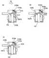
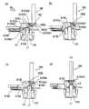
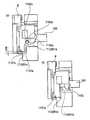
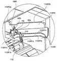
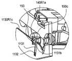
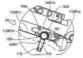
커플링의 장착 방법에 대해, 도 10 내지 도 16을 참조하여 설명이 이루어질 것이다. 도 10의 (a)는 감광 드럼 주위의 주요부에 대해서, 구동측 측면으로부터 본 확대도이다. 도 10의 (b)는 주요부의, 비구동측 측면으로부터 본 확대도이다. 도 10의 (c)는 도 10의 (a)의 S4-S4를 따라 취한 단면도이다. 도 11의 (a) 및 (b)는 제2 프레임 유닛의 주요 부재의 부착 전의 상태를 도시하는 분해 사시도이다. 도 11의 (c)는 도 11의 (a)의 S5-S5를 따라 취한 단면도이다. 도 12는 부착 후의 상태를 도시하는 단면도이다. 도 13은 도 11의 (a)의 S6-S6를 따라 취한 단면도이다. 도 14는 도 13의 상태로부터 커플링 및 감광 드럼을 90° 회전시킨 후의 상태를 도시하는 단면도이다. 도 15는 드럼축 및 커플링의 조합된 상태를 도시하는 사시도이다. 도 15의 (a1) - (a5)는 감광 드럼의 축선 방향으로부터 본 정면도이며, 도 15의 (b1) - (b5)는 사시도이다. 도 16은 커플링이 프로세스 카트리지 내에서 경사진 상태를 도시하는 사시도이다.A mounting method of the coupling will be described with reference to Figs. 10 to 16. Fig. 10 (a) is an enlarged view of a main portion around the photosensitive drum as viewed from the drive side. Fig. 10 (b) is an enlarged view of the main part as viewed from the non-driven side. 10 (c) is a cross-sectional view taken along line S4-S4 in FIG. 10 (a). 11 (a) and 11 (b) are exploded perspective views showing a state before the main member of the second frame unit is attached. 11 (c) is a cross-sectional view taken along line S5-S5 in Fig. 11 (a). 12 is a sectional view showing a state after attachment. 13 is a cross-sectional view taken along line S6-S6 in Fig. 11 (a). 14 is a cross-sectional view showing the state after the coupling and the photosensitive drum are rotated 90 占 from the state of Fig. 15 is a perspective view showing a combined state of the drum shaft and the coupling. Fig. 15 (a1) - (a5) is a front view seen from the axial direction of the photosensitive drum, and (b1) - (b5) in Fig. 15 is a perspective view. 16 is a perspective view showing a state in which the coupling is inclined in the process cartridge.
도 15에 도시된 바와 같이, 커플링(150)은 축선(L2)이 (감광 드럼(107)과 동축인) 드럼축(153)의 축선(L1)에 대해 임의의 방향으로 경사질 수 있도록 장착된다.15, the
도 15의 (a1) 및 도 15의 (b1)에서, 커플링(150)의 축선(L2)은 드럼축(153)의 축선(L1)과 동축이다. 커플링(150)이 이러한 상태로부터 상방으로 경사진 상태가 도 15의 (a2) 및 (b2)에 도시되어 있다. 이러한 도면에 도시된 바와 같이, 커플링(150)이 개구부(150g)측을 향해 경사질 때, 개구부(150g)는 핀(155)을 따라 이동한다. 결과적으로, 커플링(150)은 핀(155)의 축선과 직교하는 축선(AX)을 중심으로 경사진다.15 (a1) and 15 (b1), the axis L2 of the
도 15의 (a3) 및 (b3)에서, 커플링(150)이 우측으로 경사진 상태가 도시되어 있다. 이러한 도면에 도시된 바와 같이, 커플링(150)이 개구부(150g)의 직교 방향으로 경사질 때, 개구부(150g)는 핀(155)을 중심으로 회전한다. 회전 축선은 핀(155)의 축선(AY)이다.15 (a3) and (b3), a state in which the
커플링(150)이 하방으로 경사진 상태가 도 15의 (a4) 및 (b4)에 도시되어 있고, 커플링(150)이 좌측으로 경사진 상태가 도 15의 (a5) 및 (b5)에 도시되어 있다. 회전 축선(AX, AY)은 위에서 설명되었다.The state in which the
위에서 설명한 경사 방향과 다른 방향, 예를 들어 도 15의 (a1)에서의 45° 방향 등에 있어서, 경사는 축선(AX) 및 AY의 방향으로의 회전을 조합함으로써 이루어진다. 따라서, 축선(L2)은 축선(L1)에 대해 임의의 방향으로 피벗될 수 있다.In the direction different from the above-described inclination direction, for example, the 45 占 direction in (a1) of Fig. 15, the inclination is achieved by combining the rotation in the direction of the axis AX and the direction of AY. Thus, the axis L2 can be pivoted in any direction with respect to the axis L1.
특히, 전달면(150h: 회전력 전달부)은 핀(155: 회전력 수용부)에 대해 이동 가능하다. 그리고, 전달면(150h) 및 핀(155)은 커플링(150)의 회전 방향으로 서로 결합된다. 이러한 방식으로, 커플링(150)은 카트리지에 장착된다. 이를 달성하기 위해, 간극이 전달면(150h)과 핀(155) 사이에 제공된다. 이에 의해, 커플링(150)은 축선(L1)에 대해여 사실상 모든 방향에 걸쳐 피벗 가능하다.In particular, the transfer surface 150h (torque transmitting portion) is movable relative to the pin 155 (torque receiving portion). Then, the transfer surface 150h and the
전술한 바와 같이, 개구부(150g)는 적어도 핀(155)의 돌출 방향과 교차하는 방향(커플링(150)의 회전 축선 방향)으로 연장된다. 그러므로, 커플링(150)은 모든 방향으로 피벗 가능하다.As described above, the
축선(L2)은 축선(L1)에 대해 임의의 방향으로 기울어지거나 경사질 수 있다고 서술했다. 그러나, 축선(L2)은 커플링(150) 내에서 360°의 전범위에서 소정의 각도로 선형으로 경사질 필요는 없다. 예를 들어, 개구부(150g)는 원주 방향으로 약간 더 넓게 선택될 수 있다. 이렇게 함으로써, 축선(L2)이 축선(L1)에 대해 경사질 때, 소정의 각도로 선형으로 경사질 수 없는 경우이더라도, 커플링(150)은 축선(L2)에 대해 약간의 각도로 회전할 수 있다. 그러므로, 이는 소정의 각도로 경사질 수 있다. 바꾸어 말하면, 개구부(150g)의 회전 방향으로의 유격량은 필요하다면 적절하게 선택된다.The axis L2 is inclined or inclined in an arbitrary direction with respect to the axis L1. However, the axis L2 need not be linearly inclined at a predetermined angle above 360 deg. In the
이러한 방식으로, 커플링(150)은 드럼축(153: 회전력 수용 부재)에 대해 사실상 전체 원주부에 걸쳐 회전 또는 선회 가능하다. 특히, 커플링(150)은 드럼축(153)에 대해 사실상 전체 원주부에 걸쳐 피벗 가능하다.In this way, the
또한, 이상의 설명으로부터 이해될 바와 같이, 커플링(150)은 드럼축(153)의 원주 방향으로 그리고 사실상 그에 걸쳐 선회할 수 있다. 여기서, 선회 운동은 커플링(150) 자체가 축선(L2)을 중심으로 회전하는 운동이 아니고, 경사진 축선(L2)이 감광 드럼의 축선(L1)을 중심으로 회전하지만, 여기서 선회는 본질적으로 커플링(150)의 축선(L2)에 대한 커플링의 회전을 배제하지 않는다.Further, as will be appreciated from the above description, the
부품들을 조립하는 과정이 설명될 것이다.The process of assembling parts will be described.
먼저, 감광 드럼(107)이 도 11의 (a) 및 도 11의 (b)의 방향(X1)으로 장착된다. 이때, 플랜지(151)의 베어링부(151d)가 제2 프레임(118)의 중심 설정부(118h)와 사실상 동축으로 결합하게 된다. 또한, 플랜지(152(a))의 베어링 구멍(152a: 도 7)이 제2 프레임(118)의 중심 설정부(118g)와 사실상 동축으로 결합된다.First, the
드럼 접지축(154)이 방향(X2)으로 삽입된다. 그리고, 중심 설정부(154b)가 베어링 구멍(152a: 도 6의 (b)) 및 중심 설정 구멍(118g: 도 10의 (b))을 통해 관통된다. 이때, 중심 설정부(154b) 및 베어링 구멍(152a)은 감광 드럼(107)이 회전 가능하도록 지지된다. 다른 한편으로, 중심 설정부(154b) 및 중심 설정 구멍(118g)은 억지 끼워 맞춤 등에 의해 고정식으로 지지된다. 이에 의해, 감광 드럼(107)은 제2 프레임에 대해 회전 가능하게 지지된다. 대안적으로, 이는 플랜지(152)에 대해 회전 불가능하게 고정될 수 있고, 드럼 접지축(154: 중심 설정부(154b))은 제2 프레임(118)에 회전 가능하게 장착될 수 있다.The
커플링(150) 및 베어링 부재(157)가 방향(X3)으로 삽입된다. 먼저, 구동부(150b)가 축선(L2: 도 11의 (c))을 X3와 평행하게 유지하면서, 방향(X3) 하류측을 향해 삽입된다. 이때, 핀(155)의 위상과 개구부(150g)의 위상이 서로 정합되고, 핀(155)은 개구부(150g1 또는 150g2) 내로 삽입된다. 그리고, 드럼축(153)의 자유 단부(153b)가 드럼 베어링면(150i)에 맞닿는다. 자유 단부(153b)는 구면이며, 드럼 베어링면(150i)은 원추면이다. 즉, 오목부인 원추면의 드럼 베어링면(150i)과, 볼록부인 드럼축(153)의 자유 단부(153b)가 서로 접촉한다. 그러므로, 구동부(150b)는 자유 단부(153b)에 대해 위치가 설정된다. 전술한 바와 같이, 커플링(150)이 장치 본체(A)로부터의 회전력의 전달에 의해 회전하면, 개구부(150g) 내에 위치된 핀(155)은 회전력 전달면(150h1 또는 150h2: 회전력 전달부)에 의해 밀린다 (도 8의 (b)). 이에 의해, 회전력이 감광 드럼(107)에 전달된다. 그 후에, 결합부(157d)가 방향(X3)에 대해 하류에서 삽입된다. 이에 의해, 커플링(150)의 일부가 공간부(157b) 내에 수납된다. 그리고, 결합부(157d)는 감광 드럼(107)이 회전 가능하도록, 플랜지(151)의 베어링부(151d)를 지지한다. 또한, 결합부(157d)는 제2 프레임(118)의 중심 설정부(118h)와 결합한다. 베어링 부재(157)의 맞닿음면(157f)은 제2 프레임(118)의 맞닿음면(118j)에 맞닿는다. 그리고, 나사(158a, 158b)가 구멍(157g1 또는 157g2)을 통과하여, 제2 프레임(118)의 나사 구멍(118k1, 118k2)에 고정되어, 베어링 부재(157)는 제2 프레임(118)에 고정된다 (도 12).The
커플링(150)의 다양한 부분의 치수가 설명될 것이다. 도 11의 (c)에 도시된 바와 같이, 피구동부(150a)의 최대 외경은 ΦD2이고, 구동부(150b)의 최대 외경은 ΦD1이고, 대기 개구부(150g)의 소경은 ΦD3이다. 또한, 핀(155)의 최대 외경은 ΦD5이고, 베어링 부재(157)의 유지 리브(157e)의 내경은 ΦD4이다. 여기서, 최대 외경은 축선(L1) 또는 축선(L2)을 중심으로 한 최대 회전 궤적의 외경이다. 이때, ΦD5 < ΦD3가 만족되므로, 커플링(150)은 방향(X3)으로의 직선 장착 동작에 의해 소정의 위치로 조립될 수 있고, 그러므로 조립성이 높다 (조립 후의 상태가 도 12에 도시되어 있음). 베어링 부재(157)의 유지 리브(157e)의 내주면의 직경(ΦD4)은 커플링(150)의 ΦD2보다 더 크고, ΦD1보다 더 작다 (ΦD2 < ΦD4 < ΦD1). 이에 의해, 방향(X3)으로 바로 부착되는 단계만이 베어링 부재(157)를 소정의 위치로 조립하는데 충분하다. 이러한 이유로, 조립성이 개선될 수 있다 (조립 후의 상태가 도 12에 도시되어 있음).The dimensions of the various portions of the
도 12에 도시된 바와 같이, 베어링 부재(157)의 유지 리브(157e)는 축선(L1) 방향에서 커플링(150)의 플랜지부(150j)에 근접하게 배치된다. 구체적으로, 축선(L1) 방향에서, 플랜지부(150j)의 일 단부면(150j1)으로부터 핀(155)의 축선(L4)까지의 거리는 n1이다. 또한, 리브(157e)의 일 단부면(157e1)으로부터 플랜지부(150j)의 타 단부면(157j2)까지의 거리는 n2이다. 거리(n2) < 거리(n1)가 만족된다.The retaining
또한, 축선(L1)과 직교하는 방향에 대해, 플랜지부(150j)와 리브(157e)는 서로에 대해 중첩되도록 배치된다. 구체적으로, 리브(157e)의 내측면(157e3)으로부터 플랜지부(150j)의 외측면(150j3)까지의 거리(n4)가 축선(L1)의 축선(L1)의 직교 방향에 대한 중첩량(n4)이다.Further, with respect to the direction orthogonal to the axial line L1, the
이러한 설정에 의해, 핀(155)은 커플링(150)으로부터 이탈되는 것이 방지된다. 즉, 커플링(150)의 움직임은 베어링 부재(157)에 의해 제한된다. 따라서, 커플링(150)은 카트리지로부터 이탈되지 않는다. 이탈의 방지는 추가의 부품이 없이 달성될 수 있다. 전술한 치수는 제조 및 조립 비용의 절감의 관점에서 바람직하다. 그러나, 본 발명은 이러한 치수로 제한되지 않는다.With this setting, the
전술한 바와 같이 (도 10의 (c) 및 도 13), 커플링(150)의 오목부(150q)인 수용면(150i)이 돌출부인 드럼축(153)의 자유 단부면(153b)과 접촉한다. 그러므로, 커플링(150)은 자유 단부(153b: 구면)를 따라 자유 단부(153b: 구면)의 중심(P2)에 대해 선회된다. 바꾸어 말하면, 축선(L2)은 드럼축(153)의 위상에 관계없이 사실상 모든 방향으로 피벗 가능하다. 커플링(150)의 축선(L2)은 사실상 모든 방향으로 피벗 가능하다. 후술할 바와 같이, 커플링(150)이 구동축(180)과 결합할 수 있게 하기 위해, 축선(L2)은 결합 직전에, 축선(L1)에 대한 카트리지(B)의 장착 방향에 대한 하류를 향해 경사진다. 바꾸어 말하면, 도 16에 도시된 바와 같이, 축선(L2)은 피구동부(150a)가 감광 드럼(107)(드럼축(153))의 축선(L1)에 대해 장착 방향(X4)에 대한 하류측에 위치하도록 경사진다. 도 16의 (a) - (c)에서, 피구동부(150a)의 위치들이 서로에 대해 약간 상이하지만, 이들은 어떠한 경우에도 장착 방향(X4)에 대해 하류측에 위치된다.The receiving
더 상세한 설명이 이루어질 것이다.A more detailed description will be provided.
도 12에 도시된 바와 같이, 구동부(150b)의 최대 외경부와 베어링 부재(157) 사이의 거리(n3)는 약간의 간극이 그들 사이에 제공되도록 선택된다. 이에 의해, 커플링(150)은 피벗 가능하다.As shown in Fig. 12, the distance n3 between the maximum outer diameter portion of the driving
도 9에 도시된 바와 같이, 리브(157e)는 반원형 리브이다. 리브(157e)는 카트리지(B)의 장착 방향(X4)에 대해 하류에 배치된다. 그러므로, 도 10의 (c)에 도시된 바와 같이, 축선(L2)의 피구동부(150a)측이 방향(X4)으로 크게 피벗 가능하다. 바꾸어 말하면, 축선(L2)의 구동부(150b)측은 리브(157e)가 배치되지 않은 위상(도 9의 (a))에서 각도(α3)의 방향으로 크게 피벗 가능하다. 도 10의 (c)는 축선(L2)이 경사진 상태를 도시한다. 또한, 이는 도 10의 (c)에 도시된 경사진 축선(L2)의 상태로부터 도 13에 도시된 축선(L1)에 대해 사실상 평행한 상태로 피벗할 수도 있다. 이러한 방식으로, 리브(157e)가 배치된다. 이에 의해, 커플링(150)은 카트리지(B)에 간단한 방법으로 장착될 수 있다. 아울러, 또한, 드럼축(153)이 어떤 위상에서 정지해도, 축선(L2)은 축선(L1)에 대해 피벗 가능하다. 리브는 반원형 리브로 제한되지 않는다. 커플링(150)이 소정의 방향으로 피벗 가능하고, 커플링(150)을 카트리지(B)(감광 드럼(107))에 장착하는 것이 가능하면, 임의의 리브가 사용 가능하다. 이러한 방식으로, 리브(157e)는 커플링(150)의 경사 방향을 조절하기 위한 조절 수단으로서의 기능을 갖는다.As shown in Fig. 9, the
또한, 리브(157e)로부터 플랜지부(150j)까지의 축선(L1) 방향으로의 거리(n2: 도 12)는 핀(155)의 중심으로부터 구동부(150b)측 모서리까지의 거리(n1)보다 더 짧다. 이에 의해, 핀(155)은 개구부(150g)로부터 이탈하지 않는다.12) in the direction of the axis L1 from the
전술한 바와 같이, 커플링(150)은 사실상 드럼축(153) 및 드럼 베어링(157) 모두에 의해 지지된다. 특히, 커플링(150)은 사실상 드럼축(153)과 드럼 베어링(157)에 의해 카트리지(B)에 장착된다.As described above, the
커플링(150)은 드럼축(153)에 대한 축선(L1) 방향으로의 유격(거리(n2))을 갖는다. 그러므로, 수용면(150i: 원추면)은 드럼축 자유 단부(153b: 구면)와 꼭 맞게 접촉하지 않을 수 있다. 바꾸어 말하면, 피벗 중심은 구면의 곡률 중심(P2)으로부터 편위될 수 있다. 그러나, 이러한 경우에도, 축선(L2)은 축선(L1)에 대해 피벗 가능하다. 이러한 이유로, 본 실시예의 목적이 달성될 수 있다.The
또한, 축선(L1)과 축선(L2) 사이의 최대 가능 경사 각도(α4: 도 10의 (c))는 축선(L2)과 수용면(150i) 사이의 테이퍼 각도(α1: 도 8의 (f))의 절반이다. 수용면(150i)은 원추 형상을 갖고, 드럼축(153)은 원통 형상을 갖는다. 이러한 이유로, 각도(α1/2)의 간극(g)이 이들 사이에 제공된다. 이에 의해, 테이퍼 각도(α1)가 변화하고, 그러므로 커플링(150)의 경사 각도(α4)는 최적 값으로 설정된다. 이러한 방식으로, 수용면(150i)이 원추면이므로, 드럼축(153)의 원통부(153a)는 단순한 원통 형상이면 충분하다. 바꾸어 말하면, 드럼축은 복잡한 구성을 가질 필요가 없다. 그러므로, 드럼축의 가공 비용이 억제될 수 있다.The maximum
또한, 도 10의 (c)에 도시된 바와 같이, 커플링(150)이 경사지면, 커플링의 일부가 플랜지(151)의 공간부(151e: 빗금) 내로 들어갈 수 있다. 이에 의해, 기어부(151c)의 경량화 공동(151e: 공간부)이 낭비 없이 사용될 수 있다. 그러므로, 공간의 효과적인 사용이 행해질 수 있다. 또한, 경량화 공동(151e: 공간부)은 보통은 사용되지 않는다.10 (c), when the
전술한 바와 같이, 도 10의 (c)의 실시예에서, 커플링(150)은 축선(L2) 방향에 대해 기어부(151c)를 중첩하는 위치에 위치할 수 있다. 기어부(151c)를 갖지 않는 플랜지의 경우에, 커플링(150)의 일부가 실린더(107a) 내로 추가로 진입할 수 있다.As described above, in the embodiment of Fig. 10C, the
축선(L2)이 경사질 때, 개구부(150g)의 폭은 핀(155)이 간섭하지 않도록 핀(155)의 크기를 고려하여 선택된다.When the axis L2 is inclined, the width of the
특히, 전달면(150h: 회전력 전달부)은 핀(155: 회전력 수용부)에 대해 이동 가능하다. 그리고, 전달면(150h)과 핀(155)은 커플링(150)의 회전 방향으로 서로 결합된다. 이러한 방식으로, 커플링(150)은 카트리지에 장착된다. 이를 달성하기 위해, 간극이 전달면(150h)과 핀(155) 사이에 제공된다. 이에 의해, 커플링(150)은 축선(L1)에 대해 사실상 모든 방향으로 피벗 가능하다.In particular, the transfer surface 150h (torque transmitting portion) is movable relative to the pin 155 (torque receiving portion). Then, the transfer surface 150h and the
피구동부(150a) 측이 방향(X5)으로 경사질 때의 플랜지부(150j)의 위치가 도 14에서 영역(T1)에 의해 도시되어 있다. 도면에 도시된 바와 같이, 커플링(150)이 경사지더라도, 핀(155)과의 간섭은 발생하지 않고, 그러므로 플랜지부(150j)는 커플링(150)의 전체 원주부에 걸쳐 제공될 수 있다 (도 8의 (b)). 바꾸어 말하면, 축 수용면(150i)은 원추 형상을 갖고, 그러므로 커플링(150)이 경사지면, 핀(155)은 영역(T1) 내로 진입하지 않는다. 이러한 이유로, 커플링(150)의 절결 범위가 최소화된다. 그러므로, 커플링(150)의 강성이 보장될 수 있다.The position of the
전술한 장착 과정에서, 방향(X2)으로의 과정(비구동측) 및 방향(X3)으로의 과정(구동측)은 바뀔 수 있다.In the above-described mounting process, the process (driving side) in the direction X2 and the process (driving side) in the direction X3 can be changed.
베어링 부재(157)는 제2 프레임(118)에 대해 나사 상에서 고정되는 것으로 설명되었다. 그러나, 본 발명은 이러한 예로 제한되지 않는다. 예를 들어, 본딩처럼, 베어링 부재(157)가 제2 프레임(118)에 고정 가능하다면, 임의의 방법이 사용 가능할 것이다.The bearing
(8) 장치 본체의 구동축 및 구동 구조(8) Drive shaft and drive structure of the apparatus main body
도 17을 참조하여, 장치 본체(A) 내에서 감광 드럼(107)을 구동하기 위한 구조에 관한 설명이 이루어질 것이다. 도 17의 (a)는 카트리지(B)가 장치 본체(A)에 장착되지 않은 상태에서의 구동측의 측판의 부분 절결된 사시도이다. 도 17의 (b)는 드럼 구동 구조만을 도시하는 사시도이다. 도 17의 (c)는 도 17의 (b)의 S7-S7을 따라 취한 단면도이다.Referring to Fig. 17, a structure for driving the
구동축(180)은 전술한 드럼축(153)과 사실상 유사한 구조를 갖는다. 바꾸어 말하면, 자유 단부(180b)는 반구면을 형성한다. 또한, 이는 중심을 사실상 관통하는 원통 형상의 주부(180a)의 회전력 인가부로서 회전력 전달핀(182)을 갖는다. 회전력은 이러한 핀(182)에 의해 커플링(150)에 전달된다.The
구동축(180)의 축선과 사실상 동축인 드럼 구동 기어(181)가 구동축(180)의 자유 단부(180b)의 길이 방향 대향측에 제공된다. 기어(181)는 구동축(180)에 대해 회전 불가능하게 고정된다. 그러므로, 기어(181)의 회전은 구동축(180)을 회전시킬 것이다.A
또한, 기어(181)는 모터(186)로부터 회전력을 수용하기 위해 피니언 기어(187)와 결합된다. 그러므로, 모터(186)의 회전은 기어(181)를 통해 구동축(180)을 회전시킬 것이다.In addition, the
또한, 기어(181)는 베어링 부재(183, 184)에 의해 장치 본체(A)에 회전 가능하게 장착된다. 이때, 기어(181)는 구동축(180)(기어(181))의 축선 방향(L3)에 대해 이동하지 않고, 즉 이는 축선 방향(L3)에 대해 위치가 결정된다. 그러므로, 기어(181) 및 베어링 부재(183, 184)는 축선 방향에 대해 서로 근접하게 배치될 수 있다. 또한, 구동축(180)은 축선(L3) 방향에 대해 이동하지 않는다. 그러므로, 구동축(180) 및 베어링 부재(183, 184)들 사이의 간극은 구동축(180)의 회전을 허용하는 크기를 갖는다. 이러한 이유로, 기어(187)에 대한 직경 방향에 대한 기어(181)의 위치가 정확하게 결정된다.Further, the
또한, 구동이 기어(187)로부터 기어(181)로 직접 전달된다고 설명되었지만, 본 발명은 이러한 예로 제한되지 않는다. 예를 들어, 장치 본체(A)에 배치된 모터를 고려하여 복수의 기어를 사용하는 것이 만족스럽다. 대안적으로, 밸브 등에 의해 회전력을 전달하는 것이 가능하다.Further, although it has been described that the drive is directly transmitted from the
(9) 카트리지(B)를 안내하기 위한 본체측 장착 가이드(9) A body side mounting guide for guiding the cartridge (B)
도 18 및 도 19에 도시된 바와 같이, 본 실시예의 장착 수단(130)은 장치 본체(A) 내에 제공된 본체 가이드(130R1, 130R2, 130L1, 130L2)를 포함한다.18 and 19, the mounting means 130 of the present embodiment includes body guides 130R1, 130R2, 130L1, and 130L2 provided in the apparatus main body A. As shown in Figs.
이들은 장치 본체(A) 내에 제공된 카트리지 장착 공간(카트리지 설치부(130a))의 양측면(도 18의 구동측면, 구동되지 않는 도 19의 측면)과 대향하여 제공된다. 본체 가이드(130R1, 130R2)는 카트리지(B)의 구동측과 대향하여 본체측에 제공되고, 이들은 카트리지(B)의 장착 방향을 따라 연장된다. 다른 한편으로, 본체 가이드(130L1, 130L2)는 카트리지(B)의 비구동측과 대향하여 본체측에 제공되고, 이들은 카트리지(B)의 장착 방향을 따라 연장된다. 본체 가이드(130R1, 130R2) 및 본체 가이드(130L1, 130L2)는 서로 대향한다. 장치 본체(A)에 카트리지(B)를 장착할 때, 이러한 가이드(130R1, 130R2, 130L1, 130L2)는 후술할 바와 같이 카트리지 가이드를 안내한다. 장치 본체(A)에 카트리지(B)를 장착할 때, 축(109a)을 중심으로 장치 본체(A)에 대해 개방 및 폐쇄될 수 있는 카트리지 도어(109)가 개방된다. 그리고, 카트리지(B)의 장치 본체(A) 내로의 장착은 도어(109)를 폐쇄함으로써 완료된다. 장치 본체(A)로부터 카트리지(B)를 취출할 때, 도어(109)가 개방된다. 이러한 작동은 사용자에 의해 행해진다.These are provided opposite to both side surfaces (the driving side of Fig. 18, the side of Fig. 19 which is not driven) of the cartridge mounting space (
(10) 카트리지(B)의 장착 가이드 및 장치 본체(A)에 대한 위치 결정부(10) The mounting guide of the cartridge (B) and the positioning unit
도 2 및 도 3에 도시된 바와 같이, 이러한 실시예에서, 베어링 부재(157)의 외부 단부의 외주부(157a)가 카트리지 가이드(140R1)로서 기능한다. 또한, 드럼 접지축(154)의 외부 단부의 외주부(154a)가 카트리지 가이드(140L1)로서 기능한다.2 and 3, in this embodiment, the outer
또한, 제2 프레임 유닛(120)의 하나의 길이 방향 단부(구동측)는 카트리지 가이드(140R1)의 상부 상에서 카트리지 가이드(140R2)를 구비한다. 그리고, 길이 방향으로의 타 단부(비구동측)는 카트리지 가이드(140L1)의 상부 상에서 카트리지 가이드(140L2)를 구비한다.In addition, one longitudinal end (driving side) of the
특히, 감광 드럼(107)의 하나의 길이 방향 단부는 카트리지 프레임(B1)으로부터 외측으로 돌출한 카트리지측 가이드(140R1, 140R2)를 구비한다. 또한, 길이 방향 타단부는 카트리지 프레임(B1)으로부터 외측으로 돌출한 카트리지측 가이드(140L1, 140L2)를 구비한다. 가이드(140R1, 140R2, 140L1, 140L2)는 상기 길이 방향을 향해 외부로 돌출된다. 특히, 가이드(140R1, 140R2, 140L1, 140L2)는 축선(L1)을 따라 카트리지 프레임(B1)으로부터 돌출된다. 그리고, 카트리지(B)를 장치 본체(A)에 장착할 때 및 카트리지(B)를 장치 본체(A)로부터 탈착할 때, 가이드(140R1)는 가이드(130R1)에 의해 안내되고, 가이드(140R2)는 가이드(130R2)에 의해 안내된다. 또한, 카트리지(B)를 장치 본체(A)에 장착할 때 및 카트리지(B)를 장치 본체(A)로부터 탈착할 때, 가이드(140L1)는 가이드(130L1)에 의해 안내되고, 가이드(140L2)는 가이드(130L2)에 의해 안내된다. 이러한 방식으로, 카트리지(B)는 구동축(180)의 축선 방향(L3)과 사실상 직교하는 방향으로 이동하면서, 장치 본체(A)에 장착되고, 장치 본체(A)로부터 유사하게 탈착된다. 또한, 본 실시예에서, 카트리지 가이드(140R1, 140R2)는 제2 프레임(118)과 일체로 성형된다. 그러나, 분리된 부재들이 카트리지 가이드(140R1, 140R2)로서 사용될 수 있다.In particular, one longitudinal end of the
(11) 프로세스 카트리지의 장착 동작(11) Mounting operation of the process cartridge
도 20을 참조하여, 카트리지(B)의 장치 본체(A) 내로의 장착 동작이 설명될 것이다. 도 20은 장착 과정을 도시한다. 도 20은 도 18의 S9-S9을 따라 취한 단면도이다.Referring to Fig. 20, the mounting operation of the cartridge B into the apparatus main body A will be described. 20 shows a mounting process. 20 is a sectional view taken along the line S9-S9 in Fig.
도 20의 (a)에 도시된 바와 같이, 도어(109)가 사용자에 의해 개방된다. 그리고, 카트리지(B)가 장치 본체(A) 내에 제공된 카트리지 장착 수단(130: 설치부(130a))에 대해 탈착 가능하게 장착된다.As shown in Fig. 20 (a), the
카트리지(B)를 장치 본체(A)에 장착할 때, 도 20의 (b)에 도시된 바와 같이, 구동측에서, 카트리지 가이드(140R1, 140R2)가 본체 가이드(130R1, 130R2)를 따라 삽입된다. 또한, 비구동측에 대해서도, 카트리지 가이드(140L1, 140L2: 도3)가 본체 가이드(130L1, 130L2: 도 19)를 따라 삽입된다.When the cartridge B is mounted on the apparatus main body A, the cartridge guides 140R1 and 140R2 are inserted along the main body guides 130R1 and 130R2 on the drive side as shown in Fig. 20B . Also, the cartridge guides 140L1 and 140L2 (FIG. 3) are inserted along the main body guides 130L1 and 130L2 (FIG. 19) also on the non-driven side.
카트리지(B)가 화살표(X4) 방향으로 더 삽입됨에 따라, 구동축(180)과 카트리지(B) 사이의 결합이 확립되고, 그 다음 카트리지(B)가 소정의 위치(설치부(130a))에 장착(제공)된다. 바꾸어 말하면, 도 20의 (c)에 도시된 바와 같이, 카트리지 가이드(140R1)는 본체 가이드(130R1)의 위치 결정부(130R1a)에 접촉하고, 카트리지 가이드(140R2)는 본체 가이드(130R2)의 위치 결정부(130R2a)에 접촉한다. 또한, 카트리지 가이드(140L1)는 본체 가이드(130L1)의 위치 결정부(130L1a: 도 19)에 접촉하고, 카트리지 가이드(140L2)는 본체 가이드(130L2)의 위치 결정부(130L2a)에 접촉한다. 이러한 상태가 사실상 대칭이므로, 설명은 생략한다. 이러한 방식으로, 카트리지(B)는 장착 수단(130)에 의해 설치부(130a)에 탈착 가능하게 장착된다. 특히, 카트리지(B)는 장치 본체(A) 내에 위치된 상태에서 장착된다. 그리고, 카트리지(B)가 설치부(130a)에 장착된 상태에서, 구동축(180)과 커플링(150)은 서로 대해 결합 상태에 있다.The cartridge B is further inserted in the direction of the arrow X4 so that the coupling between the
특히, 커플링(150)은 후술할 바와 같이 회전력 전달 각도 위치에 있게 된다.In particular, the
화상 형성 작동은 카트리지(B)가 설치부(130a)에 장착됨으로써 가능해진다.The image forming operation is enabled by mounting the cartridge B to the mounting
카트리지(B)가 소정의 위치에 제공되면, 카트리지(B)의 가압 수용부(140R1b: 도 2)가 가압 스프링(188R: 도 18, 도 19, 도 20)으로부터 가압력을 수용한다. 또한, 가압 스프링(188L)으로부터, 카트리지(B)의 가압 수용부(140L1b: 도3)가 가압력을 수용한다. 이에 의해, 카트리지(B)(감광 드럼(107))가 장치 본체(A)의 전사 롤러, 광학 수단 등에 대해 정확하게 위치된다.When the cartridge B is provided at a predetermined position, the pressurizing receiving portion 140R1b (FIG. 2) of the cartridge B receives a pressing force from the
사용자는 전술한 바와 같이 카트리지(B)를 설치부(130a)로 진입시킬 수 있다. 대안적으로, 사용자는 카트리지(B)를 중간 위치까지 진입시키고, 최종 장착 동작은 다른 수단에 의해 이루어질 수 있다. 예를 들어, 도어(109)를 닫는 작동을 이용하여, 도어(109)의 일부가 장착 과정 중의 위치에 있는 카트리지(B)에 작용하여 카트리지(B)를 최종 장착 위치로 밀어 넣는다. 대안적으로, 사용자는 카트리지(B)를 중간까지 밀어 넣고, 그 후부터는 카트리지가 스스로의 무게에 의해 설치부(130a) 내로 낙하하게 한다.The user can enter the cartridge B into the mounting
여기서, 도 18 - 20에 도시된 바와 같이, 장치 본체(A)에 대한 카트리지(B)의 장착 및 탈착은 구동축(180)의 축선(L3: 도 21) 방향과 사실상 직교하는 방향으로의 이동에 의해 달성되고, 구동축(180)과 커플링(150) 사이의 위치는 결합 상태와 이탈 상태 사이에서 변화한다.Here, as shown in Figs. 18 to 20, the mounting and dismounting of the cartridge B relative to the apparatus main body A is performed in a direction substantially orthogonal to the axis L3 (Fig. 21) direction of the
여기서, "사실상 직교하는"에 대한 설명이 이루어질 것이다.Here, a description of "substantially orthogonal" will be made.
카트리지(B)와 장치 본체(A) 사이에서, 카트리지(B)를 원활하게 장착 및 탈착하기 위해, 작은 간극이 제공된다. 구체적으로, 작은 간극은 길이 방향에 대해 가이드(140R1)와 가이드(130R1) 사이에, 길이 방향에 대해 가이드(140R2)와 가이드(130R2) 사이에, 길이 방향에 대해 가이드(140L1)와 가이드(130L1) 사이에, 그리고 길이 방향에 대해 가이드(140L2)와 가이드(130L2) 사이에 제공된다. 그러므로, 장치 본체(A)에 대한 카트리지(B)의 장착 및 탈착 시에, 전체 카트리지(B)는 간극의 한도 내에서 약간 경사질 수 있다. 이러한 이유로, 직교성은 엄격하게 의미되지 않는다. 그러나, 이러한 경우에도, 본 발명은 효과가 달성된다. 그러므로, "사실상 직교하는"이라는 용어는 카트리지가 약간 경사진 경우를 포함한다.Between the cartridge B and the apparatus main body A, a small clearance is provided in order to smoothly mount and detach the cartridge B. Specifically, the small clearance is formed between the guide 140R1 and the guide 130R1 in the longitudinal direction, between the guide 140R2 and the guide 130R2 in the longitudinal direction, between the guide 140L1 and the guide 130L1 And between the guide 140L2 and the guide 130L2 with respect to the longitudinal direction. Therefore, upon mounting and dismounting of the cartridge B relative to the apparatus main body A, the entire cartridge B can be slightly inclined within the limit of the clearance. For this reason, orthogonality is not strictly meant. However, even in this case, the effect of the present invention is achieved. Thus, the term "substantially orthogonal" includes the case where the cartridge is slightly inclined.
(12) 커플링 결합 작동 및 구동 전달(12) coupling coupling operation and drive transmission
전술한 바와 같이, 장치 본체(A)의 소정의 위치에서 위치 결정 직전에 또는 그와 사실상 동시에, 커플링(150)은 구동축(180)과 결합된다. 특히, 커플링(150)은 회전력 절단 각도 위치에 위치한다. 여기서, 소정의 위치는 설치부(130a)이다. 도 21, 22, 및 23을 참조하여, 이러한 커플링의 결합 작동에 대해 설명이 이루어질 것이다. 도 21은 구동축과, 카트리지의 구동측의 주요부를 도시하는 사시도이다. 도 22는 장치 본체의 하부로부터 본 종단면도이다. 도 23은 장치 본체의 하부로부터 본 종단면이도다. 여기서, 결합은 축선(L2)과 축선(L3)이 서로에 대해 사실상 동축이고, 구동 전달이 가능한 상태를 의미한다.As described above, the
도 22에 도시된 바와 같이, 카트리지(B)는 구동축(180)의 축선(L3)과 사실상 직교하는 방향(화살표(X4))으로 장치 본체(A)에 장착된다. 또는, 이는 장치 본체(A)로부터 탈착된다. 결합전 각도 위치에서, 커플링(150)의 축선(L2: 도 22의 (a))은 드럼축(153)의 축선(L1: 도 22의 (a))에 대해 미리 장착 방향(X4)에 대한 하류를 향해 경사진다 (도 21의 (a) 및 도 22의 (a)).The cartridge B is mounted to the apparatus main body A in a direction (arrow X4) substantially orthogonal to the axis L3 of the
커플링을 미리 결합전 각도 위치를 향해 경사지게 하기 위해, 예를 들어, 후술하는 실시예 3 - 실시예 9의 구조가 사용된다.For example, the structure of the third to eighth embodiments described later is used to tilt the coupling toward the pre-engagement angular position in advance.
커플링(150)의 경사 때문에, 장착 방향(X4)에 대한 하류 자유 단부(150A1)는 축선(L1) 방향으로 구동축 자유 단부(180b3)보다 감광 드럼(107)에 더 가깝다. 또한, 장착 방향에 대한 상류 자유 단부(150A2)는 구동축 자유 단부(180b3)보다 핀(182)에 더 가깝다 (도 22의 (a) 및 (b)). 여기서, 자유 단부 위치는 축선(L2)의 방향에 대해 도 8의 (a) 및 (c)에 도시된 피구동부(150a)의 구동축에 가장 가까운 위치이고, 이는 축선(L2)으로부터 가장 이격된 위치이다. 바꾸어 말하면, 이는 도 8의 (a) 및 (c)에서, 커플링(150)의 회전 위상에 따라, 커플링(150)의 피구동부(150a)의 모서리선 또는 돌출부(150d)의 모서리선이다.The downstream free end 150A1 with respect to the mounting direction X4 is closer to the
커플링(150)의 자유 단부 위치(150A1)는 구동축 자유 단부(180b3)를 통과한다. 그리고, 커플링(150)이 구동축 자유 단부(180b3)를 통과한 후에, 수용면(150f: 카트리지측 접촉부) 또는 돌출부(150d: 카트리지측 접촉부)가 구동축의 자유 단부(180b: 본체측 결합부) 또는 핀(182: 본체측 결합부)과 접촉한다. 그리고, 카트리지(B)의 장착 동작에 대응하여, 축선(L2)은 축선(L1)과 사실상 정렬될 수 있도록 경사진다 (도 22의 (c)). 그리고, 커플링(150)이 상기 결합전 각도 위치로부터 경사지고 축선(L2)이 축선(L1)과 사실상 정렬되면, 회전력 전달 각도 위치가 도달된다. 그리고, 마지막으로, 카트리지(B)의 위치는 장치 본체(A)에 대해 결정된다. 여기서, 구동축(180) 및 드럼축(153)은 서로에 대해 사실상 동축이다. 또한, 수용면(150f)은 구동축(180)의 구면 자유 단부(180b)와 대향한다. 이러한 상태는 커플링(150)과 구동축(180) 사이의 결합 상태이다 (도 21의 (b) 및 도 22의 (d)). 이때, 핀(155: 도시되지 않음)은 개구부(150g) 내에 위치된다 (도 8의 (b)). 바꾸어 말하면, 핀(182)은 대기부(150k)에 위치한다. 여기서, 커플링(150)은 자유 단부(180b)를 덮는다.The free end position 150A1 of the
수용면(150f)은 오목부(150z)를 구성한다. 그리고, 오목부(150z)는 원추 형상을 갖는다.The receiving
전술한 바와 같이, 커플링(150)은 축선(L1)에 대해 피벗 가능하다. 그리고, 카트리지(B)의 이동에 대응하여, 카트리지측 접촉부인 커플링(150)의 부분(돌출부의 수용면(150f 및/또는 150d))이 본체측 결합부(구동축(180) 및/또는 핀(182))에 접촉한다. 이에 의해, 커플링(150)의 피벗 동작이 이루어진다. 도 22에 도시된 바와 같이, 커플링(150)은 구동축(180)과, 축선(L1)의 방향에 대해, 중첩된 상태로 장착된다. 그러나, 커플링(150) 및 구동축(180)은 전술한 바와 같이, 커플링의 피벗 이동에 의해 중첩 상태에서 서로에 대해 결합 가능하다.As described above, the
전술한 커플링(150)의 장착 동작은 구동축(180) 및 커플링(150)의 위상에 관계없이 수행될 수 있다. 도 15 및 도 23을 참조하여, 상세한 설명이 이루어질 것이다. 도 23은 커플링과 구동축 사이의 위상 관계를 도시한다. 도 23의 (a)에서, 카트리지의 장착 방향(X4)에 대한 하류 위치에서, 핀(182)과 수용면(150f)이 서로 대면한다. 도 23의 (b)에서, 핀(182)과 돌출부(150d)가 서로 대면한다. 도 23의 (c)에서, 자유 단부(180b)와 돌출부(150d)가 서로 대면한다. 도 23의 (d)에서, 자유 단부(180b)와 수용면(150f)이 서로 대면한다.The mounting operation of the
도 15에 도시된 바와 같이, 커플링(150)은 드럼축(153)에 대한 임의의 방향으로 피벗 가능하게 장착된다. 특히, 커플링(150)은 선회 가능하다. 그러므로, 도 23에 도시된 바와 같이, 이는 카트리지(B)의 장착 방향(X4)에 대한 드럼축(153)의 위상에 관계없이 장착 방향(X4)을 향해 경사질 수 있다. 또한, 커플링(150)의 경사 각도는 구동축(180) 및 커플링(150)의 위상에 관계없이, 자유 단부 위치(150A1)가 축선(L1)의 방향에 대해 축방향 자유 단부(180b3)보다 감광 드럼(170)에 더 가깝도록 설정된다. 또한, 커플링(150)의 경사 각도는 자유 단부 위치(150A2)가 축방향 자유 단부(180b3)보다 핀(182)에 더 가깝도록 설정된다. 이러한 설정에서, 카트리지(B)의 장착 동작에 대응하여, 자유 단부 위치(150A1)는 장착 방향(X4)으로 축방향 자유 단부(180b3)를 통과한다. 그리고, 도 23의 (a)의 경우에, 수용면(150f)은 핀(182)과 접촉한다. 도 23의 (b)의 경우에, 돌출부(150d: 결합부)는 핀(182: 회전력 인가부)과 접촉한다. 도 23의 (c)의 경우에, 돌출부(150d)는 자유 단부(180b)에 접촉한다. 도 23의 (d)의 경우에, 수용면(150f)은 자유 단부(180b)에 접촉한다. 또한, 카트리지(B)의 장착 시에 발생된 접촉력에 의해, 커플링(150)의 축선(L2)은 축선(L1)과 사실상 동축이 되도록 이동한다. 이에 의해, 커플링(150)은 구동축(180)과 결합된다. 특히, 커플링 오목부(150z)는 자유 단부(180b)를 덮는다. 이러한 이유로, 커플링(150)은 구동축(180), 커플링(150) 및 드럼축(153)의 위상에 관계없이 구동축(180)(핀(182))과 결합될 수 있다.As shown in FIG. 15, the
또한, 도 22에 도시된 바와 같이, 간극이 드럼축(153)과 커플링(150) 사이에 제공되어, 커플링은 요동(선회, 피벗) 가능하다.22, a clearance is provided between the
이러한 실시예에서, 커플링(150)은 도 22의 도면의 지면 내에서 이동한다. 그러나, 이러한 실시예의 커플링(150)은 전술한 바와 같이 선회 가능하다. 그러므로, 커플링(150)의 이동은 도 22의 도면의 지면 내에 포함되지 않은 이동을 포함할 수 있다. 이러한 경우에, 도 22의 (a)의 상태로부터 도 22의 (d)의 상태로의 변화가 발생한다. 이는 달리 기술되지 않으면 후술하는 실시예에 적용된다.In this embodiment, the
도 24를 참조하여, 감광 드럼(107)의 회전 시의 회전력 전달 작동이 설명될 것이다. 구동축(180)은 구동원(모터(186))으로부터 수용된 회전력에 의해 방향(도면, X8)으로 기어(181)와 함께 회전한다. 그리고, 구동축(180)과 일체인 핀(182: 182a1, 182a2)은 회전력 수용면(150e1 - 150e4: 회전력 수용부)들 중 임의의 하나와 접촉한다. 특히, 핀(182a1)은 회전력 수용면(150e1 - 150e4)들 중 임의의 하나와 접촉한다. 또한, 핀(182a2)은 회전력 수용면(150e1 - 150e4)들 중 임의의 하나와 접촉한다. 이에 의해, 구동축(180)의 회전력이 커플링(150)에 전달되어 커플링(150)을 회전시킨다. 또한, 커플링(150)의 회전에 의해, 커플링(150)의 회전력 전달면(150h1 또는 150h2: 회전력 전달부)은 드럼축(153)과 일체인 핀(155)에 접촉한다. 이에 의해, 구동축(180)의 회전력은 커플링(150), 회전력 전달면(150h1 또는 150h2), 핀(155), 드럼축(153), 및 드럼 플랜지(151)를 통해 감광 드럼(107)에 전달된다. 이러한 방식으로, 감광 드럼(107)이 회전된다.Referring to Fig. 24, the rotational force transmitting operation at the time of rotating the
회전력 전달 각도 위치에서, 자유 단부(153b)는 수용면(150i)과 접촉한다. 그리고, 구동축(180)의 자유 단부(180b: 위치 결정부)는 수용면(150f: 위치 결정부)과 접촉한다. 이에 의해, 커플링(150)은 구동축(180) 위에 있는 상태로 구동축(180)에 대해 위치된다 (도 22의 (d)).At the rotational force transmitting angular position, the
여기서, 이러한 실시예에서, 축선(L2)과 축선(L1)이 동축 관계로부터 다소 벗어나더라도, 커플링(150)은 회전력의 전달을 수행할 수 있고, 이는 커플링(150)이 약간 경사지기 때문이다. 이러한 경우에도, 커플링(150)은 드럼축(153) 및 구동축(180)에 대량의 추가 부하를 가하지 않으면서 회전할 수 있다. 그러므로, 조립 시의 구동축(180) 및 드럼축(153)의 고정밀 위치 배열 작동이 쉽다. 이러한 이유로, 조립 작업성이 개선될 수 있다.Here, in this embodiment, even though the axis L2 and the axis L1 deviate slightly from the coaxial relationship, the
이 또한 이러한 실시예의 효과들 중 하나이다.This is also one of the effects of this embodiment.
또한, 도 17에서, 전술한 바와 같이, 구동축(180) 및 기어(181)의 위치는 장치 본체(A)의 소정의 위치(설정부(130a))에 있어서 직경 방향 및 축선 방향에 대해 위치된다. 또한, 카트리지(B)는 전술한 바와 같이 장이 본체의 소정의 위치 내에 위치된다. 그리고, 상기 소정의 위치에 위치된 드럼축(180) 및 상기 소정의 위치에 위치된 카트리지(B)는 커플링(150)에 의해 결합된다. 커플링(150)은 감광 드럼(107)에 대해 선회(피벗) 가능하다. 이러한 이유로, 전술한 바와 같이, 커플링(150)은 소정의 위치에 위치된 구동축(180) 및 소정의 위치에 위치된 카트리지(B) 때문에, 회전력을 원활하게 전달할 수 있다. 바꾸어 말하면, 구동축(180)과 감광 드럼(107) 사이에 다소의 축방향 어긋남이 있더라도, 커플링(150)은 회전력을 원활하게 전달할 수 있다.17, the positions of the
이 또한 이러한 실시예의 효과들 중 하나이다.This is also one of the effects of this embodiment.
또한, 전술한 바와 같이, 카트리지(B)는 소정의 위치에 위치된다. 이러한 이유로, 카트리지(B)의 구성 요소인 감광 드럼(107)이 장치 본체(A)에 대해 정확하게 위치된다. 그러므로, 감광 드럼(107)과, 광학 수단(101), 전사 롤러(104) 또는 기록 재료(102) 사이의 공간적 관계가 높은 정밀도로 유지될 수 있다. 바꾸어 말하면, 이러한 위치 편차가 감소될 수 있다.Further, as described above, the cartridge B is positioned at a predetermined position. For this reason, the
커플링(150)은 구동축(180)에 접촉한다. 이에 의해, 커플링(150)이 결합전 각도 위치로부터 회전력 전달 각도 위치로 선회한다고 서술하였지만, 본 발명은 이러한 예로 제한되지 않는다. 예를 들어, 장치 본체의 구동축 이외의 위치에 본체측 결합부로서 맞닿음부를 제공하는 것이 가능하다. 그리고, 카트리지(B)의 장착 과정에서, 자유 단부 위치(150A1)가 구동축 자유 단부(180b3)를 통과한 후에, 커플링(150)의 일부(카트리지측 접촉부)가 이러한 맞닿음부와 접촉한다. 이에 의해, 커플링은 요동 방향(피벗 방향)의 힘을 받을 수 있고, 이는 또한 축선(L2)이 축선(L3)과 사실상 동축이 되도록 선회될 수 있다 (피벗). 바꾸어 말하면, 축선(L1)이 카트리지(B)의 장착 동작과 연동하여 축선(L3)과 사실상 동축인 위치일 수 있다면, 다른 수단이 가능하다.The
(13) 커플링의 이탈 동작, 및 카트리지의 제거 동작(13) the releasing operation of the coupling, and the removing operation of the cartridge
도 25를 참조하여, 장치 본체(A)로부터 카트리지(B)를 취출할 때의 구동축(180)으로부터 커플링(150)을 이탈시키기 위한 작동이 설명될 것이다. 도 25는 장치 본체 하방으로부터 본 종단면도이다.Referring to Fig. 25, the operation for releasing the
먼저, 카트리지(B)를 탈착할 때의 핀(182)의 위치가 설명될 것이다. 화상 형성이 종료하면, 상기 설명으로부터 명백한 바와 같이, 핀(182)은 대기부(150k1 - 150k4: 도 8)들 중 임의의 2개에 위치된다. 그리고, 핀(155)은 개구부(150g1 또는 150g2) 내에 위치된다.First, the position of the
카트리지(B)를 취출하기 위한 동작과 연동하여 구동축(180)으로부터 커플링(180)을 이탈시키기 위한 동작에 대한 설명이 이루어질 것이다.A description will be given of an operation for releasing the
도 25에 도시된 바와 같이, 카트리지(B)는 장치 본체(A)로부터의 탈착 시에, 축선(L3)과 사실상 직교하는 방향(화살표(X6)의 방향)으로 취출된다.25, the cartridge B is taken out in the direction (the direction of the arrow X6) which is substantially orthogonal to the axial line L3 at the time of detachment from the apparatus main body A. As shown in Fig.
드럼축(153)에 대한 구동이 정지된 상태에서, 축선(L2)은 커플링(150) 내의 축선(L1)에 대해 사실상 동축이다 (회전력 전달 각도 위치)(도 25의 (a)). 그리고, 드럼축(153)은 카트리지(B)와 함께 탈착 방향(X6)으로 이동하고, 탈착 방향에 대한 커플링(150) 상류의 수용면(150f) 또는 돌출부(150d)는 적어도 구동축(180)의 자유 단부(180b)에 접촉한다 (도 25의 (a)). 그리고, 축선(L2)은 탈착 방향(X6)에 대한 상류를 향해 경사지기 시작한다 (도 25의 (b)). 이러한 방향은 카트리지(B)의 장착 시의 커플링(150)의 경사 방향과 동일하다 (결합전 각도 위치). 이것은 탈착 방향(X6)에 대한 상류 자유 단부(150A3)가 이러한 카트리지(B)의 장치 본체(A)로부터의 탈착 동작에 의해 자유 단부(180b)에 접촉한 상태에서 이동한다. 상세하게는, 카트리지(B)의 탈착 방향으로의 이동에 대응하여, 카트리지측 접촉부인 커플링(150)의 일부(돌출부의 수용면(150f 및/또는 150d))가 본체측 결합부(구동축(180) 및/또는 핀(182))와 접촉하면서, 커플링이 이동한다. 그리고, 축선(L2)에서, 자유 단부(150A3)는 자유 단부(180b3)로 경사진다 (이탈 각도 위치)(도 25의 (c)). 그리고, 이러한 상태에서, 커플링(150)은 자유 단부(180b3)에 접촉하면서 구동축(180)을 통과하고, 구동축(180)으로부터 이탈된다 (도 25의 (d)). 그 후에, 카트리지(B)는 도 20에서 설명된 장착 과정과 반대인 과정을 따르고, 장치 본체(A)로부터 취출된다.The axis L2 is substantially coaxial with respect to the axis L1 in the coupling 150 (rotational force transmitting angle position) (Fig. 25 (a)) in a state in which the driving to the
상기 설명으로부터 명백할 바와 같이, 축선(L1)에 대한 결합전 각도 위치의 각도는 축선(L1)에 대한 이탈 각도 위치의 각도보다 더 크다. 이는 자유 단부 위치(150A1)가 커플링의 결합 시에 부품들의 치수 공차를 고려하여 결합전 각도 위치에서 자유 단부(180b3)를 확실하게 통과하는 것이 바람직하기 때문이다. 특히, 결합전 각도 위치에서 커플링(150)과 자유 단부(180b3) 사이에 간극이 존재하는 것이 바람직하다 (도 22의 (b)). 대조적으로, 커플링 이탈 시에, 축선(L2)은 이탈 각도 위치에서 카트리지의 탈착 동작과 연동하여 경사진다. 그러므로, 커플링(150A3)은 자유 단부(180b3)를 따라 이동한다. 바꾸어 말하면, 커플링의 카트리지 탈착 방향에 대한 상류부와 구동축의 자유 단부가 사실상 동일한 위치에 있다 (도 25의 (c)). 이러한 이유로, 축선(L1)에 대한 결합전 각도 위치의 각도는 축선(L1)에 대한 이탈 각도 위치의 각도보다 더 크다.As will be apparent from the above description, the angle of the angular position before engagement with respect to axis L1 is greater than the angle of the angular deviation position with respect to axis L1. This is because it is preferable that the free end position 150A1 surely passes through the free end portion 180b3 at the pre-engagement angular position in consideration of the dimensional tolerance of the parts when engaging the coupling. Particularly, it is preferable that there is a gap between the
또한, 장치 본체(A)에 카트리지(B)를 장착하는 경우와 유사하게, 카트리지(B)는 커플링(150)과 핀(182) 사이의 위상차에 관계없이 취출될 수 있다.The cartridge B can be taken out regardless of the phase difference between the
도 22에 도시된 바와 같이, 커플링(150)의 회전력 전달 각도 위치에서, 커플링(150)의 축선(L1)에 대한 각도는 카트리지(B)가 장치 본체(A)에 장착된 상태에서, 커플링(150)이 구동축(180)으로부터의 회전력의 전달을 받아서 회전하도록 되어 있다.22, the angle of the
커플링(150)의 회전력 전달 각도 위치는 감광 드럼을 회전시키기 위한 회전력을 드럼에 전달하기 위한 위치이다.The rotational force transmitting angular position of the
또한, 커플링(150)의 결합전 각도 위치에서, 커플링(150)의 축선(L1)에 대한 각도 위치는 커플링(150)이 카트리지(B)의 장치 본체(A)에 대한 장착 동작 시에 구동축(180)과 결합되기 직전의 상태에 있도록 되어 있다. 특히, 이는 커플링(150)의 하류 자유 단부(150A1)가 카트리지(B)의 장착 방향에 대해 구동축(180)을 통과할 수 있는 축선(L1)에 대한 각도 위치이다.
The angular position of the
또한, 커플링(150)의 이탈 각도 위치는 커플링(150)이 구동축(180)으로부터 이탈하는 경우에, 장치 본체(A)로부터 카트리지(B)를 취출하는 시점에서의 커플링(150)의 축선(L1)에 대한 각도 위치이다. 특히, 도 25에 도시된 바와 같이, 이는 커플링(150)의 자유 단부(150A3)가 카트리지(B)의 제거 방향에 대해 구동축(180)을 통과할 수 있는 축선(L1)에 대한 각도 위치이다.The disengaging angular position of the
결합전 각도 위치 또는 이탈 각도 위치에서 축선(L2)이 축선(L1)과 이루는 각도(θ2)는 회전력 전달 각도 위치에서 축선(L2)이 축선(L1)과 이루는 각도(θ1)보다 더 크다. 각도(θ1)에 관해, 0°가 바람직하다. 그러나, 이러한 실시예에서, 각도(θ1)가 약 15° 미만이면, 회전력의 원활한 전달이 달성된다. 이 또한 이러한 실시예의 효과들 중 하나이다. 각도(θ2)에 관해, 약 20 내지 60°의 범위가 바람직하다.The angle? 2 formed by the axial line L2 with the axial line L1 at the pre-engagement angular position or the release angular position is larger than the angle? 1 formed by the axial line L2 with the axial line L1 at the rotational force transmitting angular position. With respect to the angle [theta] 1, 0 [deg.] Is preferable. However, in this embodiment, when the angle [theta] 1 is less than about 15 [deg.], Smooth transfer of the rotational force is achieved. This is also one of the effects of this embodiment. With respect to the angle [theta] 2, a range of about 20 to 60 [deg.] Is preferable.
전술한 바와 같이, 커플링은 바람직하게는 축선(L1)에 대해 피벗 가능하게 장착된다. 그리고, 축선(L1)의 방향에 대해 구동축(180)과 중첩하는 상태의 커플링(150)은 카트리지(B)의 탈착 동작에 대응하여 경사지기 때문에, 구동축(180)으로부터 이탈될 수 있다. 특히, 카트리지(B)를 구동축(180)의 축선 방향과 사실상 직교하는 방향으로 이동시킴으로써, 구동축(180)을 덮는 커플링(150)은 구동축(180)으로부터 이탈될 수 있다.As described above, the coupling is preferably pivotably mounted about the axis L1. The
전술한 설명에서, 커플링(150)의 수용면(150f) 또는 돌출부(150d)는 탈착 방향(X6)으로의 카트리지(B)의 이동과 연동하여 자유 단부(180b: 핀(182))와 접촉한다. 이에 의해, 축선(L1)이 탈착 방향 하류로 경사지기 시작한다고 설명하였다. 그러나, 본 발명은 이러한 예로 제한되지 않는다. 예를 들어, 커플링(150)은 미리 탈착 방향으로 상류를 향해 가압되도록 구조를 갖는다. 그리고, 카트리지(B)의 이동에 대응하여, 이러한 가압력은 탈착 방향으로의 하류를 향한 축선(L1)의 경사를 시작한다. 그리고, 자유 단부(150A3)는 자유 단부(180b3)를 통과하고, 커플링(150)은 구동축(180)으로부터 이탈된다. 바꾸어 말하면, 탈착 방향에 대한 상류측의 수용면(150f) 또는 돌출부(150d)는 자유 단부(180b)와 접촉하지 않고, 그러므로 이는 구동축(180)으로부터 이탈될 수 있다. 이러한 이유로, 축선(L1)이 카트리지(B)의 탈착 방향과 연동하여 경사질 수 있으면, 임의의 구조가 적용될 수 있다.The receiving
커플링(150)이 구동축(180)에 장착되기 직전의 시점에서, 커플링(150)의 피구동부는 장착 방향에 대한 하류를 향해 경사지도록 경사진다. 바꾸어 말하면, 커플링(150)은 미리 결합전 각도 위치의 상태에 놓인다.At a point in time immediately before the
상기에서, 도 25의 도면의 지면 내에서의 이동이 설명되었지만, 이동은 도 22의 경우에서와 같은 선회를 포함할 수 있다.In the above, movement in the paper plane of the drawing of Fig. 25 has been described, but the movement may include the same turning as in the case of Fig.
그에 대한 구조에 관해, 실시예 2 이후에서 설명될 임의의 구조가 사용 가능하다.With respect to the structure therefor, any structure to be described later in Embodiment 2 is usable.
도 26 및 도 27을 참조하여, 드럼축의 다른 실시예에 대한 설명이 이루어질 것이다. 도 26은 드럼축 부근의 사시도이다. 도 27은 특징부를 도시한다.Referring to Figs. 26 and 27, description will be made of another embodiment of the drum shaft. 26 is a perspective view of the vicinity of the drum axis. Fig. 27 shows a characteristic portion.
전술한 실시예에서, 드럼축(153)의 자유 단부는 구면으로 형성되고, 커플링(150)은 구면과 접촉한다. 그러나, 도 26의 (a) 및 도 27의 (a)에 도시된 바와 같이, 드럼축(1153)의 자유 단부(1153b)는 평면일 수 있다. 이러한 실시예의 경우에, 주연면의 모서리부(1153c)는 커플링(150)의 원추면과 접촉하고, 이에 의해 회전이 전달된다. 이러한 구조에서도, 축선(L2)은 축선(L1)에 대해 확실하게 경사질 수 있다. 이러한 실시예의 경우에, 구면 가공에 대한 필요성이 없다. 그러므로, 가공 비용이 절감될 수 있다.In the above-described embodiment, the free end of the
전술한 실시예에서, 다른 회전력 전달 핀이 드럼축에 장착된다. 그러나, 도 26의 (b) 및 도 27의 (b)에 도시된 바와 같이, 드럼축(1253)과 핀(1253c)을 일체로 성형하는 것이 가능하다. 사출 성형 등을 사용한 일체형 성형의 경우에, 기하학적 높이가 높아진다. 이러한 경우에, 핀(1253c)은 드럼축(1253)과 일체로 형성될 수 있다. 이러한 이유로, 구동 전달부(1253d)의 넓은 영역이 제공될 수 있다. 그러므로, 회전 토크는 수지 재료로 만들어진 드럼축에 확실하게 전달될 수 있다. 또한, 일체형 성형이 이용되므로, 가공 비용이 절감된다.In the above-described embodiment, another torque transmitting pin is mounted on the drum shaft. However, as shown in Figs. 26 (b) and 27 (b), it is possible to integrally form the
도 26의 (c) 및 도 27의 (c)에 도시된 바와 같이, 회전력 전달 핀(1355: 회전력 수용 부재)의 대향 단부(1355a1, 1355a2)들은 억지 끼워 맞춤 등에 의해, 커플링(150)의 대기 개구부(1350g1 또는 1350g2)에 미리 고정된다. 그 후에, 나사 슬롯 형상(오목)으로 형성된 자유 단부(1353c1, 1353c2)를 갖는 드럼축(1353)을 삽입하는 것이 가능하다. 이때, 커플링(1350)의 피벗성을 제공하기 위해, 드럼축(1353)의 자유 단부(도시되지 않음)에 대한 핀(1355)의 결합부(1355b)는 구 형상으로 형성된다. 따라서, 핀(1355: 회전력 인가부)은 미리 고정된다. 이에 의해, 커플링(1350)의 개구부(1350g)의 크기가 감소될 수 있다. 그러므로, 커플링(1350)의 강성이 증가될 수 있다.The opposite ends 1355a1 and 1355a2 of the rotation force transmitting pin 1355 (rotational force receiving member) are engaged with each other by the interference fit or the like, as shown in Figures 26 (c) and 27 (c) Is pre-fixed to the atmospheric opening 1350g1 or 1350g2. Thereafter, it is possible to insert the
상기에서, 축선(L1)의 경사가 드럼축의 자유 단부를 따라 이루어지는 구조가 설명되었다. 그러나, 도 26의 (d), 도 26의 (e), 및 도 27의 (d)에 도시된 바와 같이, 드럼축(1453)의 축선 상에서 접촉 부재(1457)의 접촉면(1457a)을 따라 경사지는 것이 가능하다. 이러한 경우에, 드럼축(1453)의 자유 단부면(1453b)은 접촉 부재(1457)의 단부면에 필적할 만한 높이를 갖는다. 또한, 자유 단부면(1453b)을 넘어 돌출된 회전력 전달 핀(1453c: 회전력 전달 부재)은 커플링(1450)의 대기 개구부(1450g) 내로 삽입된다. 핀(1453c)은 커플링(1450)의 회전력 전달면(1450h: 회전력 전달부)에 접촉한다. 이에 의해, 회전력은 드럼(107)에 전달된다. 이러한 방식으로, 커플링(1450)이 경사질 때의 접촉면(1457a)은 접촉 부재(1457) 내에 제공된다. 이에 의해, 드럼축을 직접 가공할 필요가 없다. 그러므로, 가공 비용이 낮춰질 수 있다.In the above, the structure in which the inclination of the axis L1 is formed along the free end of the drum shaft has been described. However, as shown in Figs. 26 (d), 26 (e), and 27 (d), along the
또한, 유사하게, 자유 단부의 구면은 분리된 부재의 성형된 수지 부품일 수 있다. 이러한 경우에, 축의 가공 비용이 낮춰질 수 있다. 이는 절삭 등에 의해 가공되는 축의 구성이 단순화될 수 있기 때문이다. 또한, 축방향 자유 단부에서의 구면의 범위가 감소될 때, 고도의 정확성을 요구하는 가공의 범위가 작아질 수 있다. 이에 의해, 가공 비용이 낮춰질 수 있다.Similarly, the spherical surface of the free end may be a molded resin part of the separated member. In this case, the machining cost of the shaft can be lowered. This is because the configuration of the shaft machined by cutting or the like can be simplified. Also, when the range of the spherical surface at the free end in the axial direction is reduced, the range of machining that requires a high degree of accuracy can be reduced. Thus, the machining cost can be lowered.
도 28을 참조하여, 구동축의 다른 실시예에 대한 설명이 이루어질 것이다. 도 28은 드럼축 및 드럼 구동 기어의 사시도이다.Referring to Fig. 28, description will be made of another embodiment of the drive shaft. 28 is a perspective view of the drum shaft and the drum driving gear;
먼저, 도 28의 (a)에 도시된 바와 같이, 구동축(1180)의 자유 단부는 평면(1180b)으로 만들어진다. 이에 의해, 축의 구성이 단순하므로, 가공 비용이 낮춰질 수 있다.First, as shown in Fig. 28 (a), the free end of the
또한, 도 28의 (b)에 도시된 바와 같이, 회전력 인가부(1280(1280c1, 1280c2): 구동 전달부)를 구동축(1280)과 일체로 성형하는 것이 가능하다. 구동축(1280)이 성형된 수지 부품일 때, 회전력 인가부가 일체로 성형될 수 있다. 그러므로, 비용 절감이 달성될 수 있다. 평면부가 1280b에 의해 표시되어 있다.28 (b), it is possible to form the rotational force applying portions 1280 (1280c1, 1280c2): a drive transmitting portion) integrally with the
또한, 도 28의 (c)에 도시된 바와 같이, 구동축(1380)의 자유 단부(1380b)의 범위가 감소된다. 이러한 목적으로, 축 자유 단부(1380c)의 외경을 주부(1380a)의 외경보다 더 작게 만드는 것이 가능하다. 전술한 바와 같이, 자유 단부(1380b)는 커플링(150)의 위치를 결정하기 위해, 소정량의 정확성을 요구한다. 그러므로, 구면 범위는 커플링의 접촉부로만 제한된다. 이에 의해, 마무리 정확성이 요구되는 면 이외의 부분은 생략된다. 이에 의해, 가공 비용이 낮춰진다. 또한, 유사하게, 불필요한 구면의 자유 단부를 절삭하는 것이 가능하다. 핀(회전력 인가부)이 1382에 의해 표시되어 있다.28 (c), the range of the
축선(L1) 방향에 대한 감광 드럼(107)의 위치 설정 방법이 설명될 것이다. 바꾸어 말하면, 커플링(1550)은 테이퍼면(1550e, 1550h: 경사면)을 구비한다. 그리고, 힘이 구동축(180)의 회전에 의해 추진 방향으로 생성된다. 커플링(1550) 및 감광 드럼(107)의 축선(L1) 방향에 대한 위치 설정은 이러한 추력에 의해 이루어진다. 도 29 및 도 30을 참조하여, 이것이 상세하게 설명될 것이다. 도 29는 커플링만의 사시도 및 평면도이다. 도 30은 구동축, 드럼축, 및 커플링을 도시하는 분해 사시도이다.A method of positioning the
도 29의 (b)에 도시된 바와 같이, 회전력 수용면(1550e: 경사면(회전력 수용부))은 축선(L2)에 대해 각도(α5)만큼 경사진다. 구동축(180)이 방향(T1)으로 회전하면, 핀(182)과 회전력 수용면(1550e)이 서로 접촉한다. 그 다음, 분력이 방향(T2)으로 커플링(1550)에 인가되고, 이는 방향(T2)으로 이동한다. 그리고, 커플링(1550)은 구동축 수용면(1550f: 도 30의 (a))이 구동축(180)의 자유 단부(180b)에 맞닿을 때까지 축선 방향으로 이동한다. 이에 의해, 축선(L2) 방향에 대한 커플링(1550)의 위치가 결정된다. 또한, 구동축(180)의 자유 단부(180b)는 원통면으로 형성되고, 수용면(1550f)은 원추면을 갖는다. 그러므로, 축선(L2)과 직교하는 방향에 대해, 구동축(180)에 대한 피구동부(1550a)의 위치가 결정된다. 커플링(1550)이 드럼(107)에 장착된 경우에, 드럼(107) 또한 방향(T2)으로 추가되는 힘의 크기에 따라 축선 방향으로 이동한다. 이러한 경우에, 길이 방향에 대해, 장치 본체에 대한 드럼(107)의 위치가 결정된다. 드럼(107)은 카트리지 프레임(B1) 내에서 길이 방향으로 유격을 가지고 장착된다.The rotational
도 29의 (c)에 도시된 바와 같이, 회전력 전달면(1550h: 회전력 전달부)은 축선(L2)에 대한 각도(α6)만큼 경사진다. 커플링(1550)이 방향(T1)으로 회전할 때, 전달면(1550h)과 핀(155)이 서로에 대해 맞닿는다. 그 다음, 분력이 방향(T2)으로 핀(155)에 인가되고, 이는 방향(T2)으로 이동한다. 그리고, 드럼축(153)은 드럼축(153)의 자유 단부(153b)가 커플링(1550)의 드럼 베어링면(1550i: 도 30의 (b))에 접촉할 때까지 이동한다. 이에 의해, 축선(L2) 방향에 대한 드럼축(155: 감광 드럼)의 위치가 결정된다. 또한, 드럼 베어링면(1550i)은 원추면을 갖고, 드럼축(153)의 자유 단부(153b)는 구면으로 형성된다. 그러므로, 축선(L2)과 직교하는 방향에 대해, 드럼축(153)에 대한 구동부(1550b)의 위치가 결정된다.The
테이퍼각(α5, α6)은 커플링 및 감광 드럼을 추진 방향으로 이동시키는데 효과적인 힘이 생성될 정도로 설정된다. 그러나, 이들의 힘은 감광 드럼(107)의 회전 토크에 따라 다르다. 그러나, 추진 방향으로의 위치를 결정하는데 효과적인 수단이 제공되면, 테이퍼각(α5, α6)은 작을 수 있다.The taper angles? 5 and? 6 are set to such an extent that an effective force is generated to move the coupling and the photosensitive drum in the propelling direction. However, these forces are different depending on the rotation torque of the
전술한 바와 같이, 축선(L2) 방향으로 커플링을 당기기 위한 테이퍼 및 직교 방향에 대한 축선(L2)에서의 위치를 결정하기 위한 원추면이 제공된다. 이에 의해, 커플링의 축선(L1) 방향에 대한 위치 및 축선(L1)과 직교하는 방향에 대한 위치가 동시에 결정된다. 또한, 커플링은 회전력을 확실하게 전달할 수 있다. 또한, 커플링의 회전력 수용면(회전력 수용부) 또는 회전력 전달면(회전력 전달부)이 전술한 바와 같은 테이퍼각을 갖지 않는 경우와 비교하여, 구동축의 회전력 인가부와 커플링의 회전력 수용부 사이의 접촉이 안정될 수 있다. 또한, 드럼축의 회전력 수용부와 커플링의 회전력 전달부 사이의 접촉식 맞닿음이 안정될 수 있다.As described above, a taper for pulling the coupling in the direction of the axis L2 and a conical surface for determining the position at the axis L2 with respect to the orthogonal direction are provided. Thus, the position of the coupling with respect to the axial direction L1 and the position with respect to the direction perpendicular to the axial line L1 are simultaneously determined. Further, the coupling can reliably transmit the rotational force. Further, as compared with the case where the rotational force receiving surface (rotational force receiving portion) or the rotational force transmitting surface (rotational force transmitting portion) of the coupling does not have the taper angle as described above, the rotational force receiving portion Can be stabilized. In addition, the contact abutment between the rotational force receiving portion of the drum shaft and the rotational force transmitting portion of the coupling can be stabilized.
그러나, 축선(L2) 방향으로 커플링을 당기기 위한 테이퍼면(경사면) 및 직교 방향에 대한 축선(L2)의 위치를 결정하기 위한 원추면은 생략될 수 있다. 예를 들어, 축선(L2) 방향으로의 당기기 위한 테이퍼 대신에, 축선(L2) 방향으로 드럼을 가압하기 위한 부품을 추가하는 것이 가능하다. 이하에서, 특별한 언급이 없는 한, 테이퍼면 및 원추면이 제공된다. 또한, 테이퍼면 및 원추면은 전술한 커플링(150) 내에도 제공된다.However, the tapered surface (inclined surface) for pulling the coupling in the axial direction L2 and the conical surface for determining the position of the axial line L2 with respect to the orthogonal direction may be omitted. For example, it is possible to add a component for pressing the drum in the direction of the axis L2 instead of a taper for pulling in the direction of the axis L2. Hereinafter, unless otherwise specified, tapered surfaces and conical surfaces are provided. The tapered surface and the conical surface are also provided in the
도 31을 참조하여, 커플링의 카트리지에 대한 경사 방향을 조절하기 위한 조절 수단이 설명될 것이다. 도 31의 (a)는 프로세스 카트리지의 구동측의 주요 부품을 도시하는 측면도이고, 도 31의 (b)는 도 31의 (a)의 S7-S7을 따라 취한 단면도이다.Referring to Fig. 31, the adjustment means for adjusting the tilting direction of the coupling with respect to the cartridge will be described. 31 (a) is a side view showing the main components on the drive side of the process cartridge, and Fig. 31 (b) is a sectional view taken along line S7-S7 in Fig. 31 (a).
이러한 실시예에서, 장치 본체의 커플링(150)과 구동축(180)은 조절 수단을 제공함으로써 확실하게 결합될 수 있다.In this embodiment, the
이러한 실시예에서, 조절 수단으로서, 조절부(1557h1 또는 1557h2)가 드럼 베어링 부재(1557) 상에 제공된다. 커플링(150)은 조절 수단에 의해 카트리지(B)에 대해 선회 방향으로 조절될 수 있다. 구조는 커플링(150)이 구동축(180)과 결합하기 직전의 시점에서, 이러한 조절부(1557h1 또는 1557h2)가 카트리지(B)의 장착 방향에 대해 평행하도록 되어 있다. 또한, 간격(D6)은 커플링(150)의 구동부(150b)의 외경(D7)보다 약간 더 크다. 이렇게 함으로써, 커플링(150)은 카트리지(B)의 장착 방향(X4)으로만 피벗 가능하다. 또한, 커플링(150)은 드럼축(153)에 대해 임의의 방향으로 경사질 수 있다. 그러므로, 드럼축(153)의 위상에 관계없이, 커플링(150)은 조절된 방향으로 경사질 수 있다. 그러므로, 커플링(150)의 개구부(150m)는 구동축(180)을 더 확실하게 수용할 수 있다. 이에 의해, 커플링(150)은 구동축(180)과 더 확실하게 결합될 수 있다.In this embodiment, as the adjusting means, the adjusting portion 1557h1 or 1557h2 is provided on the
도 32를 참조하여, 커플링의 경사 방향을 조절하기 위한 다른 구조가 설명될 것이다. 도 32의 (a)는 장치 본체 구동측의 내부를 도시하는 사시도이고, 도 32의 (b)는 장착 방향(X4)에 대한 상류로부터 본 카트리지의 측면도이다.32, another structure for adjusting the inclination direction of the coupling will be described. Fig. 32 (a) is a perspective view showing the inside of the apparatus main assembly drive side, and Fig. 32 (b) is a side view of the cartridge viewed from upstream in the mounting direction X4.
조절부(1557h1 또는 1557h2)는 전술한 설명에서 카트리지(B) 내에 제공되었다. 이러한 실시예에서, 장치 본체(A)의 구동축의 장착 가이드(1630R1)의 일부가 리브형 조절부(1630R1a)이다. 조절부(1630R1a)는 커플링(150)의 선회 방향을 조절하기 위한 조절 수단이다. 그리고, 구조는 사용자가 카트리지(B)를 삽입할 때, 커플링(150)의 연결부(150c)의 외주부가 조절부(1630R1a)의 상부면(1630R1a-1)에 접촉하도록 되어 있다. 이에 의해, 커플링(150)은 상부면(1630R1a-1)에 의해 안내된다. 이러한 이유로, 커플링(150)의 경사 방향이 조절된다. 또한, 전술한 실시예와 유사하게, 드럼축(153)의 위상에 관계없이, 커플링(150)은 그가 조절되는 방향으로 경사진다.The regulator 1557h1 or 1557h2 has been provided in the cartridge B in the above description. In this embodiment, a part of the mounting guide 1630R1 of the driving shaft of the apparatus main body A is a rib-shaped adjusting portion 1630R1a. The adjusting portion 1630R1a is a controlling means for adjusting the turning direction of the
조절부(1630R1a)는 도 32의 (a)에 도시된 예에서 커플링(150) 아래에 제공된다. 그러나, 도 31에 도시된 조절부(1557h2)와 유사하게, 더 확실한 조절은 조절부가 상부측에 추가될 때 달성될 수 있다.The adjustment portion 1630R1a is provided below the
전술한 바와 같이, 이는 조절부가 카트리지(B) 내에 제공되는 구조와 조합될 수 있다. 이러한 경우에, 더 확실한 조절이 달성될 수 있다.As described above, this can be combined with the structure in which the regulating portion is provided in the cartridge B. In this case, more reliable adjustment can be achieved.
그러나, 커플링의 경사 방향을 조절하기 위한 수단이 생략될 수 있는 이러한 실시예에서, 예를 들어, 커플링(150)은 카트리지(B)의 장착 방향에 대해 하류로 미리 경사진다. 그리고, 커플링의 구동축 수용면(150f)은 확대된다. 이에 의해, 구동축(180)과 커플링(150) 사이의 결합이 확립될 수 있다.However, in this embodiment in which the means for adjusting the inclination direction of the coupling can be omitted, for example, the
또한, 상기 설명에서, 드럼 축선(L1)에 대한 커플링(150)의 결합전 각도 위치에서의 각도는 이탈 각도 위치에서의 각도보다 더 크다 (도 22 및 도 25). 그러나, 본 발명은 이러한 예로 제한되지 않는다.In addition, in the above description, the angle at the angular position before coupling of the
도 33을 참조하여, 설명이 이루어질 것이다. 도 33은 장치 본체(A)로부터 카트리지(B)를 취출하기 위한 과정을 도시하는 종단면도이다.33, description will be made. 33 is a longitudinal sectional view showing a process for taking out the cartridge B from the apparatus main body A. Fig.
장치 본체(A)로부터 카트리지(B)를 취출하기 위한 과정에서, 축선(L1)에 대한 커플링(1750)의 (도 33의 (c)의 상태에서의) 이탈 각도 위치에서의 각도는 커플링(1750)이 결합하는 시점에서의 축선(L1)에 대한 커플링(1750)의 결합전 각도 위치에서의 각도에 상응할 수 있다. 여기서, 커플링(1750)이 이탈되는 과정이 도 33의 (a) - (b) - (c) - (d)에 도시되어 있다.In the process of taking out the cartridge B from the apparatus main body A, the angle at the releasing angle position (in the state of Fig. 33 (c)) of the
특히, 설정은 커플링(1750)의 탈착 방향(X6)에 대한 상류 자유 단부(1750A3)가 구동축(180)의 자유 단부(180b3)를 통과할 때, 자유 단부(1750A3)와 자유 단부(180b3) 사이의 거리가 결합전 각도 위치의 시점에서의 거리와 동등하도록 되어 있다. 이러한 설정에서, 커플링(1750)은 구동축(180)으로부터 이탈될 수 있다.In particular, the setting is such that the free end 1750A3 and the free end 180b3, when the upstream free end 1750A3 for the detachment direction X6 of the
카트리지(B)를 탈착할 때의 다른 작동은 전술한 작동과 동일하고, 그러므로 설명은 생략될 것이다. 또한, 상기 설명에서, 장치 본체(A)에 카트리지(B)를 장착할 때, 커플링의 장착 방향에 대한 하류 자유 단부는 구동축(180)의 자유 단부보다 드럼축에 더 가깝다. 그러나, 본 발명은 이러한 예로 제한되지 않는다.The other operation when detaching the cartridge B is the same as the above-described operation, and therefore the description will be omitted. Further, in the above description, when the cartridge B is mounted on the apparatus main body A, the downstream free end with respect to the mounting direction of the coupling is closer to the drum axis than the free end of the
도 34를 참조하여, 설명이 이루어질 것이다. 도 34는 카트리지(B)의 장착 과정을 도시하기 위한 종단면도이다. 도 34에 도시된 바와 같이, 축선(L1) 방향으로의 카트리지(B)의 장착 과정의 (a) 상태에서, 장착 방향(X4)에 대한 하류 자유 단부 위치(1850A1)는 구동축 자유 단부(180b3)보다 핀(182: 회전력 인가부)에 더 가깝다. (b)의 상태에서, 자유 단부 위치(1850A1)는 자유 단부(180b)에 접촉한다. 이때, 자유 단부 위치(1850A1)는 자유 단부(180b)를 따라 드럼축(153)을 향해 이동한다. 그리고, 자유 단부 위치(1850A1)는 이러한 위치에서 구동축(180)의 자유 단부(180b3)를 통과하고, 커플링(150)은 결합전 각도 위치를 취한다 (도 34의 (c)). 그리고, 마지막으로 커플링(1850)과 구동축(180) 사이의 결합이 확립된다 (회전력 전달 각도 위치)(도 34의 (d)).Referring to Fig. 34, description will be made. Fig. 34 is a longitudinal sectional view for showing the mounting process of the cartridge B. Fig. 34, in the state (a) of the mounting process of the cartridge B in the direction of the axis L1, the downstream free end position 1850A1 with respect to the mounting direction X4 is set at the drive shaft free end 180b3, Is closer to the pin (182: rotational force applying portion) than the pin. (b), the free end position 1850A1 contacts the
이러한 실시예의 일례가 설명될 것이다.An example of such an embodiment will be described.
먼저, 드럼축(153)의 축 직경은 ΦZ1이고, 핀(155)의 축 직경은 ΦZ2이고, 길이는 Z3이다 (도 7의 (a)). 커플링(150)의 피구동부(150a)의 최대 외경은 ΦZ4이고, 돌출부(150d1 또는 150d2 또는 150d3 또는 150d4)의 내측 단부를 통과하는 가상원(C1)의 직경은 ΦZ5이고, 구동부(150b)의 최대 외경은 ΦZ6이다 (도 8의 (d) 및 (f)). 커플링(150)과 수용면(150f) 사이에 형성된 각도는 α2이고, 커플링(150)과 수용면(150i) 사이에 형성된 각도는 αl이다. 구동축(180)의 축 직경은 ΦZ7이고, 핀(182)의 축 직경은 ΦZ8이고, 길이는 Z9이다 (도 17의 (b)). 또한, 회전력 전달 각도 위치에서의 축선(L1)에 대한 각도는 β1이고, 결합전 각도 위치에서의 각도는 β2이고, 이탈 각도 위치에서의 각도는 β3이다. 이러한 예에서, Z1 = 8 mm; Z2 = 2 mm; Z3 = 12 mm; Z4 = 15 mm; Z5 = 10 mm; Z6 = 19 mm; Z7 = 8 mm; Z8 = 2 mm; Z9 = 14 mm; α1 = 70°; α2 = 120°; β1 = 0°; β2 = 35°; β3 = 30°이다.First, the shaft diameter of the
이러한 설정에서, 커플링(150)과 구동축(180) 사이의 결합이 가능하다는 것이 확인되었다. 그러나, 이러한 설정은 본 발명을 제한하지 않는다. 또한, 커플링(150)은 회전력을 드럼(107)에 높을 정밀도로 전달할 수 있다. 위에서 주어진 값은 예이고, 본 발명은 이러한 값으로 제한되지 않는다.In this setting, it has been confirmed that coupling between the
또한, 이러한 실시예에서, 핀(182: 회전력 인가부)은 구동축(180)의 자유 단부로부터 5 mm의 범위 내에 배치된다. 또한, 돌출부(150d) 내에 제공된 회전력 수용면(150e: 회전력 수용면)은 커플링(150)의 자유 단부로부터 4 mm의 범위 내에 배치된다. 이러한 방식으로, 핀(182)은 구동축(180)의 자유 단부측에 배치된다. 또한, 회전력 수용면(150e)은 커플링(150)의 자유 단부측에 배치된다.Further, in this embodiment, the pin 182 (torque application portion) is disposed within a range of 5 mm from the free end of the
이에 의해, 장치 본체(A)에 카트리지(B)를 장착할 때, 구동축(180)과 커플링(150)은 서로 원활하게 결합할 수 있다. 더 상세하게, 핀(182)과 회전력 수용면(150e)은 서로 원활하게 결합할 수 있다.Thereby, when the cartridge B is mounted on the apparatus main body A, the
또한, 장치 본체(A)로부터 카트리지(B)를 탈착할 때, 구동축(180)과 커플링(150)은 서로로부터 원활하게 이탈될 수 있다. 특히, 핀(182)과 회전력 수용면(150e)은 서로로부터 원활하게 이탈될 수 있다.Further, when the cartridge B is detached from the apparatus main body A, the
값은 예시적이고, 본 발명은 이러한 값으로 제한되지 않는다. 그러나, 전술한 효과는 이러한 수치 범위 내에 배치된 핀(182: 회전력 인가부) 및 회전력 수용면(150e)에 의해 더욱 향상된다.Values are illustrative, and the invention is not limited to these values. However, the above-described effect is further enhanced by the pin (182: rotational force applying portion) and the rotational force receiving surface (150e) arranged in this numerical range.
상기에서 설명된 바와 같이, 설명된 실시예에서, 커플링 부재(150)는 전자 사진 감광 드럼을 회전시키기 위한 회전력을 전자 사진 감광 드럼에 전달하기 위한 회전력 전달 각도 위치 및 커플링 부재(150)가 회전력 전달 각도 위치로부터 전자 사진 감광 드럼의 축선에서 멀어지게 경사진 이탈 각도 위치를 취할 수 있다. 프로세스 카트리지가 전자 사진 감광 드럼의 축선과 사실상 직교하는 방향으로 전자 사진 화상 형성 장치의 본체로부터 탈착될 때, 커플링 부재는 회전력 전달 각도 위치로부터 이탈 각도 위치로 이동한다. 프로세스 카트리지가 전자 사진 감광 드럼의 축선과 사실상 직교하는 방향으로 전자 사진 화상 형성 장치의 본체에 장착될 때, 커플링 부재는 이탈 각도 위치로부터 회전력 전달 각도 위치로 이동한다. 이는 다음의 실시예들에 적용되지만, 다음의 실시예 2는 탈착에만 관련된다.As described above, in the illustrated embodiment, the
[실시예 2][Example 2]
도 35 - 도 40을 참조하여, 본 발명이 적용되는 제2 실시예가 설명될 것이다.35 to 40, a second embodiment to which the present invention is applied will be described.
이러한 실시예의 설명에서, 실시예 1에서와 동일한 참조 번호가 이러한 실시예의 대응하는 기능을 갖는 요소에 할당되고, 상세한 설명은 간략화를 위해 생략된다. 이는 또한 하기에서 설명되는 다른 실시예들에도 적용된다.In the description of this embodiment, the same reference numerals as in
이러한 실시예는 장치 본체(A)에 대한 카트리지(B)의 장착 및 탈착의 경우뿐만 아니라 장치 본체(A)로부터 카트리지(B)의 탈착만의 경우에 대해서도 유효하다.This embodiment is effective not only in the case of mounting and dismounting of the cartridge B relative to the apparatus main body A but also in the case of removing and attaching the cartridge B from the apparatus main body A. [
특히, 구동축(180)이 정지할 때, 구동축(180)은 장치 본체(A)의 제어에 의해 소정의 위상에서 정지된다. 바꾸어 말하면, 이는 핀(182)이 소정의 위치에 있을 수 있도록 정지한다. 또한, 커플링(14150(150))의 위상은 정지된 구동축(180)의 위상과 정렬되도록 설정된다. 예를 들어, 대기부(14150k(150k))의 위치는 핀(182)의 정지 위치와 정렬될 수 있도록 설정된다. 이러한 설정에서, 장치 본체(A)에 카트리지(B)를 장착할 때, 커플링(14150(150))이 피벗되지 않더라도, 이는 구동축(180)과 대향한 상태가 될 것이다. 그리고, 구동축(180)으로부터의 회전력은 구동축(180) 회전에 의해 커플링(14150(150))에 전달된다. 이에 의해, 커플링(14150(150))은 높은 정밀도로 회전할 수 있다.In particular, when the
그러나, 이러한 실시예는 축(L3) 방향과 사실상 직교하는 방향으로 이동함으로써 장치 본체(A)로부터 카트리지(B)를 탈착할 때 유효하다. 이는 구동축(180)이 소정의 위상에서 정지하더라도, 핀(182)과 회전력 수용면(14150e1, 14150e2(150e))들이 서로에 대해 결합되기 때문이다. 이러한 이유로, 구동축(180)으로부터 커플링(14150(150))을 이탈시키기 위해, 커플링(14150(150))은 피벗할 필요가 있다.However, this embodiment is effective when the cartridge B is detached from the apparatus main body A by moving in a direction substantially orthogonal to the direction of the axis L3. This is because the
또한, 전술한 실시예 1에서, 장치 본체(A)에 대해 카트리지(B)를 장착 및 탈착할 때, 커플링(14150(150))은 피벗한다. 그러므로, 전술한 장치 본체(A)의 제어는 불필요하고, 장치 본체(A)에 카트리지(B)를 장착할 때, 정지된 구동축(180)의 위상에 따라 커플링(14150(150))의 위상을 미리 설정할 필요가 없다.Further, in
도면을 참조하여 설명이 이루어질 것이다.The description will be made with reference to the drawings.
도 35는 장치 본체의 구동축, 구동 기어, 및 구동축에 대한 위상 제어 수단을 도시하는 사시도이다. 도 36은 커플링의 사시도 및 평면도이다. 도 37은 카트리지의 장착 동작을 도시하는 사시도이다. 도 38은 카트리지 장착 시의 장착 방향에서 본 평면도이다. 도 39는 카트리지(감광 드럼)의 구동 정지 상태에서 도시하는 사시도이다. 도 40은 카트리지를 취출하기 위한 작동을 도시하는 종단면도 및 사시도이다.35 is a perspective view showing a drive shaft, a drive gear, and phase control means for the drive shaft of the main assembly of the apparatus. 36 is a perspective view and a plan view of the coupling. 37 is a perspective view showing the mounting operation of the cartridge. Fig. 38 is a plan view seen from the mounting direction when the cartridge is mounted. 39 is a perspective view showing a state in which the cartridge (photosensitive drum) is stopped from being driven. 40 is a longitudinal sectional view and a perspective view showing an operation for taking out the cartridge.
이러한 실시예에서, 핀(182)의 정지 위치의 위상을 제어할 수 있는 제어 수단(도시되지 않음)을 구비한 장치 본체(A)에 탈착 가능하게 장착될 수 있는 카트리지에 대한 설명이 이루어질 것이다. 구동축(180)의 일 단부측(도시되지 않은 감광 드럼(107)측))은 도 35의 (a)에 도시된 바와 같이, 제1 실시예의 것과 동일하고, 그러므로 설명은 생략된다. 다른 한편으로, 도 35의 (b)에 도시된 바와 같이, 타 단부측(도시되지 않은 감광 드럼(107)측의 반대측)은 구동축(180)의 구동축(180) 외주부로부터 돌출된 플래그(14195)를 구비한다. 그리고, 플래그(14195)는 회전에 의해 장치 본체(A)에 고정된 차광기(14196)를 통과한다. 그리고, 제어 수단(도시되지 않음)은 구동축(180)의 회전(예를 들어, 화상 형성 회전) 후에, 플래그(14195)가 차광기(14196)를 처음으로 차단할 때, 모터(186)가 정지하도록 제어한다. 이에 의해, 핀(182)은 구동축(180)의 회전 축에 대한 소정의 위치에서 정지한다. 모터(186)에 관해, 이러한 실시예의 경우에, 이는 바람직하게는 위치 설정 제어가 용이한 스텝 모터이다.In this embodiment, a description will be given of a cartridge detachably mountable to the apparatus main body A having control means (not shown) capable of controlling the phase of the stop position of the
도 36을 참조하여, 이러한 실시예에서 사용되는 커플링이 설명될 것이다.Referring to Figure 36, the coupling used in this embodiment will be described.
커플링(14150)은 주로 3개의 부분을 포함한다. 도 36의 (c)에 도시된 바와 같이, 이는 구동축(180)으로부터 회전력을 수용하기 위한 피구동부(14150a), 드럼축(153)에 회전력을 전달하기 위한 구동부(14150b), 및 피구동부(14150a)와 구동부(1415b)를 서로 연결하는 연결부(14150c)이다.The
피구동부(14150a)는 축선(L2)으로부터 멀어지는 방향으로 확대되는 2개의 면에 의해 구성된 구동축 삽입부(14150m)를 갖는다. 또한, 구동부(14150b)는 축선(L2)으로부터 멀리 확대되는 2개의 면으로 구성된 드럼축 삽입부(14150v)를 갖는다.The driven
삽입부(14150m)는 테이퍼진 구동축 수용면(14150f1 또는 14150f2)을 갖는다. 그리고, 각 단부면은 돌출부(14150d1 또는 14150d2)를 구비한다. 돌출부(14150d1 또는 14150d2)는 커플링(14150)의 축선(L2) 둘레의 원주부 상에 배치된다. 수용면(14150f1, 14150f2)은 도면에 도시된 바와 같이, 오목부(14150z)를 구성한다. 또한, 도 36의 (d)에 도시된 바와 같이, 시계 방향으로의 돌출부(14150d1, 14150d2)의 하류는 회전력 수용면(14150e(14150e1, 14105e2): 회전력 수용부)을 구비한다. 핀(182: 회전력 인가부)이 수용면(14150e1, 14150e2)에 맞닿는다. 인접한 돌출부(14150d1 - 14150d2)들 사이의 간격(W)은 핀(182)의 외경보다 더 커서, 핀(182)의 진입을 허용한다. 이러한 간격은 대기부(14150k)이다.The insertion portion 14150m has a tapered drive shaft receiving surface 14150f1 or 14150f2. Each end face has a protruding portion 14150d1 or 14150d2. The protrusion 14150d1 or 14150d2 is disposed on the circumference around the axis L2 of the
또한, 삽입부(14150v)는 2개의 면(14150i1, 14150i2)에 의해 구성된다. 그리고, 대기 개구부(14150g1 또는 14150g2)가 이러한 면(14150i1, 14150i2) 내에 제공된다 (도 36의 (a) 및 도 36의 (e)). 또한, 도 36의 (e)에서, 시계 방향으로의 개구부(14150g1 또는 14150g2)의 상류에, 회전력 전달면(14150h(14150h1 또는 14150h2): 회전력 전달부)이 제공된다. 그리고, 전술한 바와 같이, 핀(155a: 회전력 수용부)은 회전력 전달면(14150h1 또는 14150h2)과 접촉한다. 이에 의해, 회전력은 커플링(14150)으로부터 감광 드럼(107)에 전달된다.The
커플링(14150)의 형상에 있어서, 커플링은 카트리지가 장치의 본체에 장착된 상태에서 구동축의 자유 단부 위에 있다. 그리고, 제1 실시예에 의해 설명된 구조와 유사한 구조에서, 커플링(14150)은 드럼축(153)에 대해 임의의 방향으로 경사질 수 있다.In the configuration of the
도 37 및 도 38을 참조하여, 커플링의 장착 동작이 설명될 것이다. 도 37의 (a)는 커플링이 장착되기 전의 상태를 도시하는 사시도이다. 도 37의 (b)는 커플링이 결합된 상태를 도시하는 사시도이다. 도 38의 (a)는 장착 방향에서 본, 평면도이다. 도 38의 (b)는 장착 방향에 대한 상부로부터 본, 평면도이다.37 and 38, the mounting operation of the coupling will be described. 37 (a) is a perspective view showing a state before the coupling is mounted. 37B is a perspective view showing a state in which the coupling is engaged. 38 (a) is a plan view viewed from the mounting direction. 38 (b) is a plan view as viewed from the top with respect to the mounting direction.
핀(182: 회전력 인가부)의 축선(L3)은 전술한 제어 수단에 의해 장착 방향(X4)에 대해 평행하다. 또한, 카트리지에 관해, 위상은 수용면(14150f1, 14150f2)들이 장착 방향(X4)과 직교하는 방향으로 서로로부터 대향하도록 정렬된다 (도 37의 (a)). 위상을 정렬시키기 위한 구조로서, 수용면(14150f1 또는 14150f2)의 임의의 일 측면이 예를 들어, 도면에 도시된 바와 같이, 베어링 부재(14157) 상에 제공된 표식(14157z)과 정렬된다. 이는 공장으로부터 카트리지를 운송하기 전에 수행된다. 그러나, 사용자는 장치 본체에 카트리지(B)를 장착하기 전에, 수행할 수 있다. 또한, 다른 위상 조정 수단이 사용될 수 있다. 이렇게 함으로써, 커플링(14150)과 구동축(180: 핀(182))은 위치 관계에 있어서, 도 38의 (a)에 도시된 바와 같이, 장착 방향에 대해 서로 간섭하지 않는다. 그러므로, 커플링(14150)과 구동축(180)은 문제없이 결합될 수 있다 (도 37의 (b)). 그리고, 구동축(180)은 방향(X8)으로 회전하여, 핀(182)이 수용면(14150e1, 14150e2)에 접촉한다. 이에 의해, 회전력이 감광 드럼(107)에 전달된다.The axis L3 of the pin 182 (rotational force applying portion) is parallel to the mounting direction X4 by the control means described above. Further, with respect to the cartridge, the phase is aligned such that the receiving surfaces 14150f1 and 14150f2 are opposed to each other in a direction orthogonal to the mounting direction X4 (Fig. 37 (a)). As a structure for aligning the phases, any one side of the receiving surface 14150f1 or 14150f2 is aligned with the
도 39 및 도 40을 참조하여, 장치 본체(A)로부터 카트리지(B)를 취출하기 위한 작동과 연동하여 커플링(14150)이 구동축(180)으로부터 이탈되는 작동에 관한 설명이 이루어질 것이다. 구동축(180)에 대한 핀(182)의 위상은 제어 수단에 의해 소정의 위치에 정지한다. 전술한 바와 같이, 카트리지(B)의 장착의 용이함을 고려할 때, 핀(182)이 카트리지 장착 방향(X6)에 대해 평행한 위상에서 정지하는 것이 바람직하다 (도 39의 (b)). 카트리지(B)를 취출할 때의 작동이 도 40에 도시되어 있다. 이러한 상태에서 (도 40의 (a1) 및 (b1)), 커플링(14150)은 회전력 전달 각도 위치를 취하고, 축선(L2)과 축선(L1)은 서로 사실상 동축이다. 이때, 카트리지(B)를 장착하는 경우와 유사하게, 커플링(14150)은 드럼축(153)에 대해 임의의 방향으로 경사질 수 있다 (도 40의 (a1) 및 도 40의 (b1)). 그러므로, 축선(L2)은 카트리지(B)의 탈착 작동과 연동하여 축선(L1)에 대한 탈착 방향으로부터 반대 방향으로 경사진다. 특히, 카트리지(B)는 축선(L3)과 사실상 직교하는 방향(화살표(X6)의 방향)으로 탈착된다. 그리고, 카트리지의 탈착 과정에서, 축선(L2)은 커플링(14150)의 자유 단부(14150A3)가 구동축(180)의 자유 단부(180b)를 따를 때까지 경사진다 (이탈 각도 위치). 또는, 이는 축선(L2)이 자유 단부(180b3)에 대해 드럼축(153)측에 위치할 때까지 경사진다 (도 40의 (a2) 및 도 40의 (b2)). 이러한 상태에서, 커플링(14150)은 자유 단부(180b3) 부근을 통과한다. 이렇게 함으로써, 커플링(14150)은 구동축(180)으로부터 탈착된다.39 and 40, a description will be made as to the operation in which the
또한, 도 39의 (a)에 도시된 바와 같이, 핀(182)의 축선은 카트리지 탈착 방향(X6)과 직교하는 상태에서 정지할 수 있다. 핀(182)은 평시에 제어 수단의 제어에 의해 도 39의 (b)에 도시된 위치에서 정지한다. 그러나, 장치(프린터)의 전압원이 꺼질 수 있고, 제어 수단은 작동하지 않을 수 있다. 핀(182)은 이러한 경우에 도 39의 (a)에 도시된 바와 같은 위치에서 정지할 수 있다. 그러나, 이러한 경우에도, 축선(L2)은 전술한 경우와 유사하게 축선(L1)에 대해 경사지고, 제거 작동이 가능하다. 장치가 구동 정지 상태에 있을 때, 핀(182)은 탈착 방향(X6)에 대해 돌출부(14150d2)를 넘어 하류에 있다. 그러므로, 커플링의 돌출부(14150d1)의 자유 단부(14150A3)는 축선(L2) 경사에 의해 핀(182)을 넘어 드럼축(153)측을 통과한다. 이에 의해, 커플링(14150)은 구동축(180)으로부터 탈착된다.39 (a), the axis of the
전술한 바와 같이, 커플링(14150)이 카트리지(B) 장착의 경우에 소정의 방법에 의해 구동축(180)에 대해 결합되더라도, 축선(L2)은 탈착 작동의 경우에 축선(L1)에 대해 경사진다. 이에 의해, 커플링(14150)은 이러한 탈착 작동에 의해서만 구동축(180)으로부터 탈착될 수 있다.As described above, although the
전술한 바와 같이, 이러한 실시예 2에 따르면, 이러한 실시예는 장치 본체(A)에 대해 카트리지(B)를 장착 및 탈착하는 경우에 추가하여, 장치의 본체로부터 카트리지를 탈착하는 경우에 대해서도 유효하다.As described above, according to the second embodiment, this embodiment is also effective for the case of detaching the cartridge from the main body of the apparatus, in addition to mounting and dismounting of the cartridge B relative to the apparatus main body A .
[실시예 3][Example 3]
도 41 - 도 45를 참조하여, 제3 실시예가 설명될 것이다.Referring to Figs. 41 to 45, a third embodiment will be described.
도 41은 장치 본체(A)의 도어가 개방된 상태를 도시하는 단면도이다. 도 42는 장착 가이드를 도시하는 사시도이다. 도 43은 카트리지의 구동측 표면의 확대도이다. 도 44는 카트리지의 구동측으로부터 본 사시도이다. 도 45는 장치 본체 내로 카트리지를 삽입하는 상태를 도시하는 도면을 도시한다.41 is a sectional view showing a state in which the door of the apparatus main body A is opened. 42 is a perspective view showing the mounting guide. 43 is an enlarged view of the drive-side surface of the cartridge. 44 is a perspective view of the cartridge as viewed from the drive side. 45 shows a view showing a state of inserting the cartridge into the apparatus main body.
이러한 실시예에서, 예를 들어, 클램쉘형 화상 형성 장치의 경우에서와 같이, 카트리지는 하방으로 장착된다. 전형적인 클램쉘형 화상 형성 장치가 도 41에 도시되어 있다. 장치 본체(A2)는 하부 케이싱(D2) 및 상부 케이싱(E2)을 포함한다. 그리고, 상부 케이싱(E2)은 도어(2109) 및 도어(2109)의 내부 노광 장치(2101)를 구비한다. 그러므로, 상부 케이싱(E2)이 상방으로 개방되면, 노광 장치(2101)는 후퇴한다. 그리고, 카트리지 설치부(2130a)의 상부가 개방된다. 사용자가 카트리지(B-2)를 설치부(2130a)에 장착할 때, 사용자는 카트리지(B-2)를 X4B 하방으로 낙하시킨다. 장착은 이로써 완료되고, 그러므로 카트리지의 장착은 용이하다. 또한, 인접한 정착 장치(105)의 걸림 제거 동작이 장치 상부로부터 이루어질 수 있다. 그러므로, 이는 걸림 제거의 용이성에 있어서 우수하다. 여기서, 걸림 제거는 공급 중에 걸린 기록 재료(102)를 제거하기 위한 동작이다.In this embodiment, as in the case of a clamshell-type image forming apparatus, for example, the cartridge is mounted downward. A typical clamshell-type image forming apparatus is shown in Fig. The apparatus main body A2 includes a lower casing D2 and an upper casing E2. The upper casing E2 includes a
더 구체적으로, 카트리지(B-2)에 대한 설치부가 설명될 것이다. 도 42에 도시된 바와 같이, 화상 형성 장치(A2)는 장착 수단(2130)으로서, 구동측에서 장착 가이드(2130R)를 구비하고, 그와 대향한 비구동측에서 도시되지 않은 장착 가이드를 구비한다. 설치부(2130a)는 대향하는 가이드들에 의해 둘러싸인 공간으로서 형성된다. 회전력은 장치 본체(A)로부터 이러한 설치부(2130a)에 제공된 카트리지(B-2)의 커플링(150)에 전달된다.More specifically, a mounting portion for the cartridge B-2 will be described. As shown in Fig. 42, the image forming apparatus A2 is a mounting means 2130, which includes a mounting
장착 가이드(2130R)는 사실상 직교하는 방향으로 연장하는 홈(2130b)을 구비한다. 또한, 카트리지(B-2)를 소정의 위치에 결정하기 위한 맞닿음부(2130Ra)가 최하부에 제공된다. 또한, 구동축(180)은 홈(2130b)으로부터 돌출한다. 카트리지(B-2)가 소정의 위치에 위치된 상태에서, 구동축(180)은 회전력을 장치 본체(A)로부터 커플링(150)에 전달한다. 또한, 카트리지(B-2)를 소정의 위치에 확실하게 위치시키기 위해, 가압 스프링(2188R)이 장착 가이드(2130R)의 하부에 제공된다. 전술한 구조에 의해, 카트리지(B-2)는 설치부(2103a) 내에 위치된다.The mounting
도 43 및 도 44에 도시된 바와 같이, 카트리지(B-2)는 카트리지측 장착 가이드(2140R1, 2140R2)를 구비한다. 카트리지(B-2)의 배향은 장착 시에 이러한 가이드에 의해 안정된다. 그리고, 장착 가이드(2140R1)는 드럼 베어링 부재(2157) 상에 일체로 형성된다. 또한, 장착 가이드(2140R2)는 사실상 장착 가이드(2140R1) 위에 제공된다. 그리고, 가이드(2140R2)는 제2 프레임(2118) 내에 제공되고, 이는 리브의 형태이다.As shown in Figs. 43 and 44, the cartridge B-2 has cartridge-side mounting guides 2140R1 and 2140R2. The orientation of the cartridge B-2 is stabilized by this guide at the time of mounting. The mounting guide 2140R1 is integrally formed on the
카트리지(B-2)의 장착 가이드(2140R1, 2140R2) 및 장치 본체(A2)의 장착 가이드(2130R)는 전술한 구조를 갖는다. 특히, 이는 도 2 및 3과 관련하여 설명된 가이드의 구조와 동일하다. 또한, 타 단부의 가이드의 구조도 동일하다. 그러므로, 카트리지(B-2)는 구동축(180)의 축선(L3) 방향과 사실상 직교하는 방향으로 장치 본체(A2)로 이동되면서 장착되고, 또한, 이는 장치 본체(A2)로부터 유사하게 탈착된다.The mounting guides 2140R1 and 2140R2 of the cartridge B-2 and the mounting guides 2130R of the apparatus main body A2 have the above-described structure. In particular, this is identical to the structure of the guide described with reference to Figures 2 and 3. The structure of the guide at the other end is also the same. Therefore, the cartridge B-2 is mounted while being moved to the apparatus main body A2 in the direction substantially orthogonal to the direction of the axis L3 of the
도 45에 도시된 바와 같이, 카트리지(B-2)를 장착할 때, 상부 케이싱(E2)은 축(2109a)에 대해 시계 방향으로 회전되고, 사용자는 카트리지(B-2)를 하부 케이싱(D2)의 상부로 이동시킨다. 이때, 커플링(150)은 자중에 의해 하방으로 경사진다 (도 43). 바꾸어 말하면, 커플링의 축선(L2)은 커플링(150)의 피구동부(150a)가 아래로 향할 수 있도록 드럼 축선(L1)에 대해 경사진다 (결합전 각도 위치).45, when the cartridge B-2 is mounted, the upper casing E2 is rotated clockwise with respect to the
또한, 실시예 1, 도 9 및 도 12에 대해 설명된 바와 같이, 반원형 유지 리브(2157e: 도 43)를 제공하는 것이 바람직하다. 이러한 실시예에서, 카트리지(B-2)의 장착 방향은 하방이다. 그러므로, 리브(2157e)는 하부에 배치된다. 이에 의해, 실시예 1에 대해 설명된 바와 같이, 축선(L1)과 축선(L2)은 서로에 대해 피벗 가능하고, 커플링(150)의 유지가 달성된다. 유지 리브는 커플링(150)이 카트리지(B-2)로부터 분리되는 것을 방지한다. 커플링(150)이 감광 드럼(107)에 장착될 때, 이는 감광 드럼(107k)으로부터 분리되는 것이 방지된다.It is also desirable to provide a
이러한 상태에서, 도 45에 도시된 바와 같이, 사용자는 카트리지(B-2)의 장착 가이드(2140R1, 2140R2)를 장치 본체(A2)의 장착 가이드(2130R)와 정렬시키면서, 카트리지(B-2)를 하방으로 하강시킨다. 카트리지(B-2)는 이러한 작동만에 의해 장치 본체(A2)의 설치부(2130a)에 장착될 수 있다. 이러한 장착 과정에서, 실시예 1(도 22)과 유사하게, 커플링(150)은 장치 본체의 구동축(180)과 결합될 수 있다 (커플링은 이러한 상태에서 회전력 전달 각도 위치를 취한다). 특히, 카트리지(B-2)를 구동축(180)의 축선(L3) 방향과 사실상 직교하는 방향으로 이동시킴으로써, 커플링(150)은 구동축(180)과 결합된다. 또한, 카트리지를 탈착할 때, 실시예 1과 유사하게, 커플링(150)은 카트리지를 탈착하는 작동만에 의해서 구동축(180)으로부터 이탈될 수 있다 (커플링은 회전력 전달 각도 위치로부터 이탈 각도 위치로 이동한다 (도 25)). 특히, 카트리지(B-2)를 구동축(180)의 축선(L3) 방향과 사실상 직교하는 방향으로 이동시킴으로써, 커플링(150)은 구동축(180)으로부터 이탈된다.45, the user places the cartridge B-2 in a state in which the mounting guides 2140R1 and 2140R2 of the cartridge B-2 are aligned with the mounting guides 2130R of the apparatus main body A2, Downward. The cartridge B-2 can be mounted to the mounting
전술한 바와 같이, 커플링이 카트리지를 장치 본체에 하방으로 장착할 때 자중에 의해 하방으로 경사지므로, 이는 장치 본체의 구동축과 확실하게 결합할 수 있다.As described above, since the coupling is inclined downwardly by its own weight when the cartridge is mounted downward on the main assembly of the apparatus, it can securely engage with the drive shaft of the main assembly of the apparatus.
이러한 실시예에서, 클램쉘형 화상 형성 장치가 설명되었다. 그러나, 본 발명은 이러한 예로 제한되지 않는다. 예를 들어, 본 실시예는 카트리지의 장착 방향이 하방이면 적용될 수 있다. 또한, 장착 경로는 하방 직선으로 제한되지 않는다. 예를 들어, 이는 카트리지의 초기 장착 단계에서 하방으로 경사질 수 있고, 마지막에는 하방이 될 수 있다. 본 실시예는 소정의 위치(카트리지 설치부)에 도달하기 직전의 장착 경로가 하방이면 유효하다.In this embodiment, a clamshell-type image forming apparatus has been described. However, the present invention is not limited to this example. For example, this embodiment can be applied when the mounting direction of the cartridge is downward. Further, the mounting path is not limited to a downward straight line. For example, it can be tilted downward at the initial mounting stage of the cartridge, and downward at the end. This embodiment is effective when the mounting path immediately before reaching a predetermined position (cartridge mounting portion) is downward.
[실시예 4][Example 4]
도 46 - 도 49를 참조하여, 본 발명의 제4 실시예가 설명될 것이다.Referring to Figs. 46 to 49, a fourth embodiment of the present invention will be described.
이러한 실시예에서, 축선(L2)을 축선(L1)에 대해 경사진 상태로 유지하기 위한 수단이 설명될 것이다.In this embodiment, the means for keeping the axis L2 tilted relative to the axis L1 will be described.
본 실시예의 이러한 부분의 설명에 관련된 부재만이 도면에 도시되어 있고, 다른 부재는 생략된다. 이는 이하에서 설명될 다른 실시예에서도 유사하다.Only the components related to the description of this part of this embodiment are shown in this figure, and the other parts are omitted. This is similar in other embodiments, which will be described below.
도 46은 드럼 베어링 부재 상에 부착된 커플링 걸림 부재(이는 본 실시예에 대해 특유함)를 도시하는 사시도이다. 도 47은 드럼 베어링 부재, 커플링, 및 드럼축을 도시하는 분해 사시도이다. 도 48은 카트리지의 구동축의 주요 부분의 확대 사시도이다. 도 49는 구동축과 커플링 사이의 결합 상태를 도시하는 사시도 및 종단면도이다.
46 is a perspective view showing a coupling engaging member (which is specific to this embodiment) attached on the drum bearing member. 47 is an exploded perspective view showing the drum bearing member, the coupling, and the drum shaft. 48 is an enlarged perspective view of a main portion of the drive shaft of the cartridge. Fig. 49 is a perspective view and a longitudinal sectional view showing the coupling state between the drive shaft and the coupling. Fig.
도 46에 도시된 바와 같이, 드럼 베어링 부재(3157)는 커플링의 일부를 둘러싸는 공간(3157b)을 갖는다. 커플링(3150)의 경사를 유지하기 위한 유지 부재인 커플링 걸림 부재(3159)가 공간을 구성하는 원통면(3157i) 상에 부착된다. 후술할 바와 같이, 이러한 걸림 부재(3159)는 축선(L2)이 축선(L1)에 대해 경사진 상태를 일시적으로 유지하기 위한 부재이다. 바꾸어 말하면, 도 48에 도시된 바와 같이, 커플링(3150)의 플랜지부(3150i)가 이러한 걸림 부재(3159)에 접촉한다. 이에 의해, 축선(L2)은 축선(L1)에 대한 카트리지의 장착 방향(X4)에 대한 하류를 향해 경사진 상태를 유지한다 (도 49의 (a1)). 그러므로, 도 46에 도시된 바와 같이, 걸림 부재(3159)는 장착 방향(X4)에 대해 베어링 부재(3157)의 상류 원통면(3157i) 상에 배치된다. 걸림 부재(3159)의 재료로서, 고무 및 탄성중합체와 같은 비교적 높은 마찰 계수를 갖는 재료 또는 스펀지 및 판스프링과 같은 탄성 재료가 적합하다. 이는 축선(L2)의 경사가 마찰력, 탄성력 등에 의해 유지될 수 있기 때문이다. 또한, 실시예 1(도 31에 도시되어 있음)과 유사하게, 베어링 부재(3157)는 경사 방향 조절 리브(3157h)를 구비한다. 커플링(3150)의 경사 방향은 이러한 리브(3157h)에 의해 확실하게 결정될 수 있다. 또한, 플랜지부(3150i)와 걸림 부재(3159)는 서로에 대해 더 확실하게 접촉할 수 있다. 도 47을 참조하여, 커플링(3150)의 조립 방법이 설명될 것이다. 도 47에 도시된 바와 같이, 핀(155: 회전력 수용부)이 커플링(3150)의 대기 공간(3150g)으로 진입한다. 또한, 커플링(3150)의 일부는 드럼 베어링 부재(3157)가 갖는 공간부(3157b) 내로 삽입된다. 이때, 바람직하게는, 리브(3157e)의 내면 단부와 걸림 부재(3159) 사이의 거리(D12)는 피구동부(3150a)의 최대 외경(ΦD10)보다 더 크게 설정된다. 또한, 거리(D12)는 구동부(3150b)의 최대 외경(ΦD11)보다 더 작게 설정된다. 이에 의해, 베어링 부재(3157)는 바로 조립될 수 있다. 그러므로, 조립 특성이 개선된다. 그러나, 본 실시예는 이러한 관계로 제한되지 않는다.As shown in Fig. 46, the
도 49를 참조하여, 커플링(3150)을 구동축(180)과 결합시키기 위한 결합 작동(카트리지의 장착 동작의 일부)이 설명될 것이다. 도 49의 (a1) 및 (b1)은 결합 직전의 상태를 도시하고, 도 49의 (a2) 및 (b2)는 결합 완료 상태를 도시한다.Referring to Fig. 49, a coupling operation (a part of the mounting operation of the cartridge) for coupling the
도 49의 (a1) 및 도 49의 (b1)에 도시된 바와 같이, 커플링(3150)의 축선(L2)은 걸림 부재(3159)의 힘에 의해 축선(L1)에 대해 장착 방향(X4)에 대한 하류를 향해 경사진다 (결합전 각도 위치). 축선(L1) 방향으로의 커플링(3150)의 이러한 경사에 의해, (장착 방향에 대한) 하류 자유 단부(3150A1)는 구동축 자유 단부(180b3)보다 감광 드럼(107)측에 더 가깝다. 그리고, (장착 방향에 대한) 상류 자유 단부(3150A1)는 구동축(180)의 자유 단부(180b3)보다 핀(182)에 더 가깝다. 또한, 이때, 전술한 바와 같이, 플랜지부(3150j)는 걸림 부재(3159)에 접촉된다. 그리고, 축선(L2)의 경사진 상태는 마찰력에 의해 유지된다.The axis L2 of the
그 후에, 카트리지(B)는 장착 방향(X4)으로 이동한다. 이에 의해, 핀(182)의 자유 단부면(180b) 또는 자유 단부는 커플링(3150)의 구동축 수용면(3150f)에 접촉한다. 그리고, 축선(L2)은 접촉력(카트리지의 장착력)에 의해 축선(L1)과 평행한 방향으로 접근한다. 이때, 플랜지부(3150j)는 걸림 부재(3159)로부터 이격되고, 비접촉 상태가 된다. 그리고, 마지막으로, 축선(L1)과 축선(L2)은 서로 사실상 동축이다. 그리고, 커플링(3150)은 회전력을 전달하기 위한 대기 상태가 된다 (도 49의 (a2) 및 (b2))(회전럭 전달 각도 위치).Thereafter, the cartridge B moves in the mounting direction X4. Thereby, the
실시예 1과 유사하게, 모터(186)로부터, 회전력이 구동축(180)을 통해 커플링(3150), 핀(155: 회전력 수용부), 드럼축(153), 및 감광 드럼(107)에 전달된다. 축선(L2)은 회전 시에 축선(L1)과 사실상 동축이다. 그러므로, 걸림 부재(3159)는 커플링(3150)과 접촉하지 않는다. 그러므로, 걸림 부재(3159)는 커플링(3150)의 회전에 영향을 주지 않는다.Rotation force is transmitted from the
또한, 작동은 카트리지(B)가 장치 본체(A)로부터 취출되는 과정에서 실시예 1과 유사한 단계를 따른다 (도 25). 바꾸어 말하면, 구동축(180)의 자유 단부(180b)는 커플링(3150)의 구동축 수용면(3150f)을 밀어낸다. 이에 의해, 축선(L2)은 축선(L1)에 대해 경사지고, 플랜지부(3150j)는 걸림 부재(3159)에 접촉하게 된다. 이에 의해, 커플링(3150)의 경사진 상태가 다시 유지된다. 바꾸어 말하면, 커플링(3150)은 회전력 전달 각도 위치로부터 결합전 각도 위치로 이동한다.In addition, the operation is similar to that of
전술한 바와 같이, 축선(L2)의 경사진 상태는 걸림 부재(3159: 유지 부재)에 의해 유지된다. 이에 의해, 커플링(3150)은 구동축(180)과 더 확실하게 결합될 수 있다.As described above, the inclined state of the axis L2 is held by the latching member 3159 (holding member). Thereby, the
이러한 실시예에서, 걸림 부재(3159)는 베어링 부재(3157)의 내면(3157i)의, 카트리지 장착 방향(X4)에 대한 최상부에 부착된다. 그러나, 본 발명은 이러한 예로 제한되지 않는다. 예를 들어, 축선(L2)이 경사질 때, 경사진 상태를 유지할 수 있는 임의의 위치가 사용 가능하다.In this embodiment, the latching
또한, 이러한 실시예에서, 걸림 부재(3159)는 구동부(3150b)측에 제공된 플랜지부(3150j)에 접촉한다 (도 49의 (b1)). 그러나, 접촉 위치는 피구동부(3150a)일 수 있다.Further, in this embodiment, the engaging
또한, 이러한 실시예에서 사용되는 걸림 부재(3159)는 베어링 부재(3157) 내의 분리된 부재이다. 그러나, 본 실시예는 이러한 예로 제한되지 않는다. 예를 들어, 걸림 부재(3159)는 베어링 부재(3157)와 일체로 성형될 수 있다 (예를 들어, 2색 성형). 또는, 베어링 부재(3157)는 걸림 부재(3159) 대신에 커플링(3150)에 직접 접촉할 수 있다. 또는 표면은 마찰 계수를 증가시킬 목적으로 거칠어질 수 있다.Also, the latching
또한, 이러한 실시예에서, 걸림 부재(3159)는 베어링 부재(3157) 상에 부착된다. 그러나, 걸림 부재(3159)가 카트리지(B)에 고정된 부재이면, 이는 임의의 위치에 부착될 수 있다.Further, in this embodiment, the latching
[실시예 5][Example 5]
도 50 - 도 53을 참조하여, 본 발명의 제5 실시예가 설명될 것이다.Referring to Figs. 50 to 53, a fifth embodiment of the present invention will be described.
본 실시예에서, 축선(L1)에 대해 축선(L2)을 경사지게 한 상태를 유지하기 위한 다른 수단이 설명될 것이다.In this embodiment, another means for maintaining the state in which the axis L2 is inclined with respect to the axis L1 will be described.
도 50은 드럼 베어링 부재에 장착된 커플링 가압 부재(본 실시예에 대해 특유함)의 분해 사시도이다. 도 51은 드럼 베어링 부재, 커플링, 및 드럼축을 도시하는 분해 사시도이다. 도 52는 카트리지의 구동측의 주요 부분의 확대 사시도이다. 도 53은 구동축과 커플링 사이의 결합 상태를 도시하는 사시도 및 종단면도이다.50 is an exploded perspective view of a coupling urging member (peculiar to the present embodiment) mounted on the drum bearing member; 51 is an exploded perspective view showing the drum bearing member, the coupling, and the drum shaft. 52 is an enlarged perspective view of a main portion on the drive side of the cartridge. 53 is a perspective view and a longitudinal sectional view showing the coupling state between the drive shaft and the coupling.
도 50에 도시된 바와 같이, 유지 구멍(4157j)이 드럼 베어링 부재(4157)의 유지 리브(4157e) 내에 제공된다. 커플링(4150)의 유지 구멍(4157j) 내에서의 경사를 유지하기 위한 유지 부재인 커플링 가압 부재(4159a, 4159b)가 장착된다. 가압 부재(4159a, 4159b)는 축선(L2)이 축선(L1)에 대해 카트리지(B-2)의 장착 방향에 대한 하류를 향해 경사지도록, 커플링(4150)을 가압한다. 각각의 가압 부재(4159a, 4159b)는 코일형 압축 스프링(탄성 재료)이다. 도 51에 도시된 바와 같이, 가압 부재(4159a, 4159b)는 커플링(4150)의 플랜지부(4150j)를 축선(L1)을 향해 가압한다 (도 51의 화살표(X13)). 가압 부재가 플랜지부(4150j)와 접촉하는 접촉 위치는 카트리지 장착 방향(X4)에 대한 드럼축(153)의 중심의 하류이다. 그러므로, 축선(L2)에 대해, 피구동부(4150a)측은 가압 부재(4159a, 4159b)에 의한 탄성력에 의해 축선(L1)에 대해 카트리지의 장착 방향(X4)에 대한 하류를 향해 경사진다 (도 52).As shown in Fig. 50, a retaining
또한, 도 50에 도시된 바와 같이, 코일 스프링인 각각의 가압 부재(4159a, 4159b)의 커플링측 자유 단부는 접촉 부재(4160a, 4160b)를 구비한다. 접촉 부재(4160a, 4160b)는 플랜지부(4150j)와 접촉한다. 그러므로, 접촉 부재(4160a, 4160b)의 재료는 바람직하게는 활주성이 높은 재료이다. 또한, 이러한 재료를 사용함으로써, 후술할 바와 같이, 회전력 전달 시에, 가압 부재(4159a, 4159b)에 의한 가압력의 커플링(4150)의 회전에 대한 영향이 경감된다. 그러나, 회전에 대한 부하가 충분히 작고, 커플링(4150)이 만족스럽게 회전하면, 접촉 부재(4160a, 4160b)는 필수적이지 않다.Further, as shown in Fig. 50, the free sides on the coupling side of the respective pressing
본 실시예에서, 2개의 가압 부재가 제공된다. 그러나, 축선(L2)이 축선(L1)에 대해 카트리지의 장착 방향에 대한 하류를 향해 경사질 수 있으면, 가압 부재의 개수는 임의적일 수 있다. 예를 들어, 단일 가압 부재의 경우에, 활성화 위치에 대해, 이는 바람직하게는 카트리지의 장착 방향(X4)에 대한 최하류 위치이다. 이에 의해, 커플링(4150)은 장착 방향에 대한 하류를 향해 안정적으로 경사질 수 있다.In this embodiment, two pressing members are provided. However, if the axis L2 can be inclined toward the downstream side with respect to the mounting direction of the cartridge with respect to the axis L1, the number of pressing members may be arbitrary. For example, in the case of a single pressing member, with respect to the activated position, it is preferably the most downstream position with respect to the mounting direction X4 of the cartridge. Thereby, the
또한, 가압 부재는 본 실시예에서 압축 코일 스프링이다. 그러나, 가압 부재로서, 탄성력이 판스프링, 비틀림 스프링, 고무, 스펀지 등에서와 같이 생성될 수 있으면, 임의의 것일 수 있다. 그러나, 축선(L2)을 경사지게 하기 위해, 소정량의 행정이 요구된다. 그러므로, 코일 스프링 등에서와 같이, 행정이 제공될 수 있는 것이 바람직하다.The pressing member is a compression coil spring in this embodiment. However, as the pressing member, any elastic force can be generated as long as it can be generated as in a leaf spring, a torsion spring, a rubber, a sponge, or the like. However, in order to tilt the axis L2, a predetermined amount of stroke is required. Therefore, as in a coil spring or the like, it is preferable that a stroke can be provided.
도 51을 참조하여, 커플링(4150)의 장착 방법에 대한 설명이 이루어질 것이다.Referring to Fig. 51, a description will be made of a mounting method of the
도 51에 도시된 바와 같이, 핀(155)은 커플링(4150)의 대기 공간(4150g)으로 진입한다. 그리고, 커플링(4150)의 일부가 드럼 베어링 부재(4157)의 공간(4157b) 내로 삽입된다. 이때, 전술한 바와 같이, 가압 부재(4159a, 4159b)가 플랜지부(4157j)를 접촉 부재(4160a, 4160b)를 통해 소정의 위치 상으로 밀어낸다. 나사(도 52의 4158a, 4158b)가 베어링 부재(4157) 내에 제공된 구멍(4157g1 또는 4157g2) 내로 끼워지고, 이에 의해 베어링 부재(4157)가 제2 프레임(1180)에 고정된다. 이에 의해, 압력 부재(4159a, 4159b)에 의한 커플링(4150)으로의 가압력이 보장될 수 있다. 그리고, 축선(L2)은 축선(L1)에 대해 경사진다 (도 52).As shown in FIG. 51, the
도 53을 참조하여, 커플링(4150)의 구동축(180)과의 결합의 작동(카트리지의 장착 동작의 일부)이 설명될 것이다. 도 53의 (a1) 및 (b1)은 결합 직전의 상태를 도시한다. 도 53의 (a2) 및 (b2)는 결합 완료 상태를 도시하고, 도 53의 (c1)은 중간 상태를 도시한다.Referring to Fig. 53, the operation of coupling (coupling part of the cartridge) of the
도 53의 (a1) 및 (b1)에서, 커플링(4150)의 축선(L2)은 미리 축선(L1)에 대해 장착 방향(X4)을 향해 경사진다 (결합전 각도 위치). 커플링(4150) 경사에 의해, 축선(L1) 방향에 대한 하류 자유 단부 위치(4150A1)는 자유 단부(180b3)보다 감광 드럼(107)에 더 가깝다. 또한, 자유 단부 위치(4150A2)는 자유 단부(180b3)보다 핀(182)에 더 가깝다. 바꾸어 말하면, 전술한 바와 같이, 커플링(4150)의 플랜지부(4150j)는 가압 부재(4159)에 의해 가압된다. 그러므로, 축선(L2)은 가압력에 의해 축선(L1)에 대해 경사진다.53 (a1) and (b1), the axis L2 of the
그 후에, 장착 방향(X4)으로 이동하는 카트리지(B)에 의해, 핀(182: 회전력 인가부)의 자유 단부면(180b) 또는 자유 단부(본체측 결합부)는 커플링(4150)의 구동축 수용면(4150f) 또는 돌출부(4150d: 카트리지측 접촉부)와 접촉하게 된다. 도 53의 (c1)은 핀(182)이 수용면(4150f)과 접촉하는 상태를 도시한다. 그리고, 축선(L2)은 접촉력(카트리지의 장착력)에 의해 축선(L1)과 평행한 방향을 향해 접근한다. 동시에, 플랜지부(4150j) 내에 제공된 스프링(4159)의 탄성력에 의해 가압되는 가압부(4150j1)가 스프링(4159)의 압축 방향으로 이동한다. 그리고, 마지막으로, 축선(L1)과 축선(L2)이 동축이 된다. 그리고, 커플링(4150)은 회전력의 전달을 이루기 위한 대기 위치를 취한다 (회전력 전달 각도 위치)(도 53의 (a2) 및 (b2)).The
실시예 1과 유사하게, 회전력은 모터(186)로부터 구동축(180)을 통해, 커플링(4150), 핀(155), 드럼축(153), 및 감광 드럼(107)에 전달된다. 가압 부재(4159)의 가압력은 회전 시에 커플링(4150) 상에서 작용한다. 그러나, 전술한 바와 같이, 가압 부재(4159)의 가압력은 접촉 부재(4160)를 통해 커플링(4150)에 작용한다. 그러므로, 커플링(4150)은 높은 부하가 없이 회전될 수 있다. 또한, 접촉 부재(4160)는 모터(186)의 구동 토크가 충분히 크면 제공되지 않을 수 있다. 이러한 경우에, 접촉 부재(4160)가 제공되지 않으면, 커플링(4150)은 높은 정밀도로 회전력을 전달할 수 있다.Similarly to
또한, 카트리지(B)가 장치 본체(A)로부터 탈착되는 과정에서, 장착 단계와 반대의 단계를 따른다. 바꾸어 말하면, 커플링(4150)은 평시에 가압 부재(4159)에 의해 장착 방향(X4)에 대한 하류로 가압된다. 그러므로, 카트리지(B)의 탈착 과정에서, 수용면(4150f)은 장착 방향(X4)에 대한 상류측에서 핀(182)의 자유 단부(182A)와 접촉한다 (도 53의 (c1)). 또한, 간극(n50)이 장착 방향(X4)에 대한 하류에서, 전달면(4150f)의 자유 단부(180b)와 구동축(180) 사이에 필수적으로 제공된다. 전술한 실시예에서, 카트리지의 탈착 과정에서, 커플링의 장착 방향(X4)에 대한 하류의 수용면(150f) 또는 돌출부(150d)는 적어도 구동축(180)의 자유 단부(180b)에 접촉하는 것으로 설명되었다 (예를 들어, 도 25). 그러나, 본 실시예에서와 같이, 커플링의 장착 방향(X4)에 대한 하류의 수용면(150f) 또는 돌출부(4150d)는 구동축(180)의 자유 단부(180)에 접촉하지 않지만, 카트리지(B)의 탈착 작동에 대응하여, 커플링(4150)은 구동축(180)으로부터 분리될 수 있다. 그리고, 커플링(4150)이 구동축(180)으로부터 이격된 후에도, 가압 부재(4159)의 가압력에 의해, 축선(L2)은 축선(L1)에 대해 장착 방향(X4)에 대한 하류를 행해 경사진다 (이탈 각도 위치). 특히, 이러한 실시예에서, 축선(L1)에 대한 결합전 각도 위치의 각도와 이탈 각도 위치의 각도는 서로 동등하다. 이는 커플링(4150)이 스프링의 탄성력에 의해 가압되기 때문이다.Further, in the process in which the cartridge B is detached from the apparatus main body A, the reverse of the mounting step is followed. In other words, the
또한, 가압 부재(4159)는 축선(L2)을 경사지게 하는 기능을 갖고, 아울러 커플링(4150)의 경사 방향을 조절하는 기능도 갖는다. 특히, 가압 부재(4159)는 또한 커플링(4150)의 경사 방향을 조절하기 위한 조절 수단으로서도 기능한다.The pressing
전술한 바와 같이, 이러한 실시예에서, 커플링(4150)은 베어링 부재(4157) 내에 제공된 가압 부재(4159)의 탄성력에 의해 가압된다. 이에 의해, 축선(L2)은 축선(L1)에 대해 경사진다. 그러므로, 커플링(4150)의 경사진 상태가 유지된다. 그러므로, 커플링(4150)은 구동축(180)과 확실하게 결합될 수 있다.As described above, in this embodiment, the
이러한 실시예에서 설명된 가압 부재(4159)는 베어링 부재(4157)의 리브(4157e) 내에 제공된다. 그러나, 본 실시예는 이러한 예로 제한되지 않는다. 예를 들어, 이는 베어링 부재(4157)의 다른 부분일 수 있고, (베어링 부재 이외에) 카트리지(B)에 고정된 임의의 부재일 수 있다.The pressing
또한, 이러한 실시예에서, 가압 부재(4159)의 가압 방향은 축선(L1) 방향이다. 그러나, 가압 방향은 축선(L2)이 카트리지(B)의 장착 방향(X4)에 대한 하류를 향해 경사지면, 임의의 방향일 수 있다.Further, in this embodiment, the pressing direction of the
또한, 카트리지(B)의 장착 방향에 대한 하류를 향해 커플링(4150)을 더 확실하게 경사지게 하기 위해, 커플링의 경사 방향을 조절하기 위한 조절부가 프로세스 카트리지 내에 제공될 수 있다 (도 31).Further, in order to more surely tilt the
또한, 이러한 실시예에서, 가압 부재(4159)의 활성화 위치는 플랜지부(4150i)이다. 그러나, 커플링의 위치는 축선(L2)이 카트리지의 장착 방향에 대한 하류를 향해 경사지면 임의적일 수 있다.Further, in this embodiment, the activation position of the
또한, 본 실시예는 실시예 4와 조합하여 실시될 수 있다. 이러한 경우에, 커플링의 장착 및 탈착 작동이 추가로 보장될 수 있다.Further, this embodiment can be implemented in combination with
[실시예 6][Example 6]
도 54 - 도 58을 참조하여, 본 발명의 제6 실시예가 설명될 것이다.Referring to Figs. 54 to 58, a sixth embodiment of the present invention will be described.
이러한 실시예에서, 축선(L1)이 축선(L1)에 대해 경사진 상태를 유지하기 위한 다른 수단이 설명될 것이다.In this embodiment, other means for maintaining the axis L1 in a tilted state relative to the axis L1 will be described.
도 54는 이러한 실시예의 프로세스 카트리지의 분해 사시도이다. 도 55는 카트리지의 구동측의 확대 측면도이다. 도 56은 드럼축, 커플링, 및 베어링 부재의 개략적인 종단면도이다. 도 57은 구동축에 대해 커플링을 장착하는 작동을 도시하는 종단면도이다. 도 58은 커플링 걸림 부재의 변형예를 도시하는 단면도이다.54 is an exploded perspective view of the process cartridge of this embodiment. 55 is an enlarged side view of the drive side of the cartridge. 56 is a schematic longitudinal sectional view of the drum shaft, the coupling, and the bearing member. 57 is a longitudinal sectional view showing the operation of mounting the coupling to the drive shaft. 58 is a sectional view showing a modified example of the coupling engagement member.
도 54 및 도 56에 도시된 바와 같이, 드럼 베어링 부재(5157)는 커플링 걸림 부재(5157k)를 구비한다. 축선(L1) 방향으로 베어링 부재(5157)를 조립할 때, 걸림 부재(5157k)의 걸림면(5157k1)의 일부가 커플링(5150)의 경사면(5150m)에 접촉하면서, 플랜지부(5150j)의 상부면(5150j1)과 결합한다. 이때, 플랜지부(5150j)는 걸림부(5157k)의 걸림면(5157k1)과 드럼축(153)의 원통부(153a) 사이에서, 회전 방향으로 유격(각도(α49))을 가지고 지지된다. 다음의 효과가 이러한 유격(각도(α49))을 제공함으로써 제공된다. 특히, 커플링(5150), 베어링 부재(5157), 및 드럼축(153)의 치수가 공차 한계 내에서 변하더라도, 상부면(5159j1)이 걸림면(5157k1) 내에 확실하게 걸릴 수 있다.As shown in Figs. 54 and 56, the
그리고, 도 56의 (a)에 도시된 바와 같이, 축선(L2)에 관해, 축선(L1)에 대한 피구동부(5150a)측은 카트리지의 장착 방향(X4)에 대한 하류를 향해 경사진다. 또한, 플랜지부(5150j)가 전체 원주부에 걸쳐 존재하므로, 이는 커플링(5150)의 위상에 관계없이 유지할 수 있다. 또한, 실시예 1에 대해 설명된 바와 같이, 커플링(5150)은 조절 수단인 조절부(5157h1 또는 5157h2: 도 55)에 의해 장착 방향(X4)으로만 경사질 수 있다. 또한, 이러한 실시예에서, 커플링 걸림 부재(5157k)는 카트리지의 장착 방향(X4)에 대한 최하류측에 제공된다.56A, the side of the driven
후술할 바와 같이, 커플링(5150)이 구동축(180)과 결합한 상태에서, 플랜지부(5150j)는 도 56의 (b)에 도시된 바와 같이 걸림 부재(5157k)로부터 해제된다. 그리고, 커플링(5150)은 걸림 부재(5157k)로부터 자유롭다. 베어링 부재(5157)의 조립의 경우에 커플링(5150)을 경사 상태를 유지할 수 없을 때, 커플링의 피구동부(5150a)는 공구 등에 의해 밀린다 (도 56의 (b), 화살표(X14)). 이렇게 함으로써, 커플링(5150)은 경사진 유지 상태로 쉽게 복귀될 수 있다 (도 56의 (a)).As will be described later, with the
또한, 리브(5157m)는 사용자가 커플링을 쉽게 만지는 것으로부터 보호하기 위해 제공된다. 리브(5157m)는 커플링의 경사진 상태에서 자유 단부 위치와 사실상 동일한 높이로 설정된다 (도 56의 (a)). 도 57을 참조하여, 커플링(5150)을 구동축(180)과 결합시키기 위한 작동(카트리지의 장착 동작의 일부)이 설명될 것이다. 도 57에서, (a)는 결합 직전의 커플링의 상태를 도시하고, (b)는 커플링(5150)의 일부가 구동축(180)을 통과한 후의 상태를 도시하고, (c)는 커플링(5150)의 경사가 구동축(180)에 의해 해제된 상태를 도시하고, (d)는 결합 상태를 도시한다.The
(a) 및 (b)의 상태에서, 커플링(5150)의 축선(L2)은 축선(L1)에 대해 장착 방향(X4)을 향해 미리 경사진다 (결합전 각도 위치). 커플링(5150) 경사에 의해, 자유 단부 위치(5150A1)는 축선(L1) 방향으로 자유 단부(180b3)보다 감광 드럼에 더 가깝다. 또한, 자유 단부 위치(5150A2)는 자유 단부(180b3)보다 핀(182)에 더 가깝다. 또한, 전술한 바와 같이, 이때, 플랜지부(5150j)는 걸림면(5157k1)과 접촉하고, 커플링(5150)의 경사 상태가 유지된다.the axial line L2 of the
그 후에, (c)에 도시된 바와 같이, 수용면(5150f) 또는 돌출부(5150d)는 장착 방향(X4)으로 이동하는 카트리지(B)에 의해 자유 단부(180b) 또는 핀(182)에 접촉한다. 플랜지부(5150j)는 접촉력에 의해 걸림면(5157k1)으로부터 분리된다. 그리고, 커플링(5150)의 베어링 부재(5157)에 대한 걸림이 해제된다. 그리고, 카트리지 장착 동작에 응답하여, 커플링은 축선(L2)이 축선(L1)과 사실상 동축이 되도록 경사진다. 플랜지부(5150j)가 통과한 후에, 걸림 부재(5157k)는 복원력에 의해 이전의 위치로 복귀한다. 이때, 커플링(5150)은 걸림 부재(5157k)로부터 자유롭다. 그리고, 마지막으로, (d)에 도시된 바와 같이, 축선(L1)과 축선(L2)은 사실상 동축이 되고, 회전 대기 상태가 확립된다 (회전력 전달 각도 위치).Thereafter, as shown in (c), the receiving
또한, 카트리지(B)가 장치 본체(A)로부터 탈착되는 과정에서 실시예 1과 유사한 단계를 따른다 (도 25). 특히, 커플링(5150)은 카트리지의 탈착 방향(X6)으로의 이동에 의해 (d), (c), (b), 및 (a)의 순서로 변화된다. 먼저, 자유 단부(180)b)가 수용면(5150f: 카트리지측 접촉부)을 민다. 이에 의해, 축선(L2)은 축선(L1)에 대해 경사지고, 플랜지부의 하부면(5150j2)은 걸림 부재(5157k)의 경사면(5157k2)에 접촉하기 시작한다. 그리고, 걸림 부재(5157k)의 탄성부(5157k3)가 구부러지고, 걸림면 자유 단부(5157k4)가 플랜지부(5150j)의 경사 궤적으로부터 이격된다 (도 57의 (c)). 또한, 플랜지부(5150j)와 걸림면(5157k1)은 카트리지가 탈착 방향(X6)으로 전진함에 따라 서로 접촉한다. 이에 의해, 커플링(5150)의 경사 각도가 유지된다 (도 57의 (b)). 특히, 커플링(5150)은 회전력 전달 각도 위치로부터 이탈 각도 위치로 선회(피벗)된다.
Further, a step similar to that of
전술한 바와 같이, 커플링(5150)의 각도 위치는 걸림 부재(5157k)에 의해 유지된다. 이에 의해, 커플링의 경사 각도가 유지된다. 그러므로, 커플링(5150)은 구동축(180)과 확실하게 결합될 수 있다. 또한, 회전 시에, 걸림 부재(5157k)는 커플링(5150)과 접촉하지 않는다. 그러므로, 안정된 회전이 커플링(5150)에 의해 달성될 수 있다.As described above, the angular position of the
도 56, 도 57, 및 도 58에 도시된 커플링의 운동은 선회 운동을 포함할 수 있다.The movement of the coupling shown in Figs. 56, 57 and 58 may include a pivot motion.
이러한 실시예에서, 걸림 부재(5157k)는 탄성부를 구비한다. 그러나, 이는 탄성부를 갖지 않는 리브일 수 있다. 특히, 걸림 부재(5157k)와 플랜지부(5150j) 사이의 결합량은 감소된다. 이에 의해, 유사한 효과가 플랜지부(5150j)를 약간 변형시킴으로써 제공될 수 있다 (도 58의 (a)).In this embodiment, the latching
또한, 걸림 부재(5157k)는 장착 방향(X4)에 대한 최하류측에 제공된다. 그러나, 축선(L2)의 소정 방향을 향한 경사가 유지될 수 있으면, 걸림 부재(5157k)의 위치는 임의적일 수 있다.Further, the latching
도 58의 (b) 및 (c)는 커플링 걸림부(5357k: 도 58의 (b), 5457k: 도 58의 (c))가 장착 방향(X4)에 대한 상류에 제공된 예를 도시한다.Figures 58 (b) and 58 (c) show an example in which a
또한, 걸림 부재(5157k)는 전술한 실시예에서 베어링 부재(5157)의 일부에 의해 구성되었다. 그러나, 그가 카트리지(B)에 고정된다면, 걸림 부재(5157k)는 베어링 부재 이외의 부재의 일부로서 구성될 수 있다. 또한, 걸림 부재는 별도의 부재일 수 있다.In addition, the engaging
또한, 본 실시예는 실시예 4 또는 실시예 5와 함께 실시될 수 있다. 이러한 경우에, 더 확실한 커플링에서의 장착 및 탈착 작동이 달성된다.In addition, this embodiment can be carried out together with
[실시예 7][Example 7]
도 59 - 도 62를 참조하여, 본 발명의 제7 실시예가 설명될 것이다.59 to 62, a seventh embodiment of the present invention will be described.
이러한 실시예에서, 커플링의 축선을 감광 드럼의 축선에 대해 경사진 상태로 유지하기 위한 다른 수단이 설명될 것이다.In this embodiment, other means for maintaining the axis of the coupling in an inclined state relative to the axis of the photosensitive drum will be described.
도 59는 드럼 베어링 부재 상에 자석 부재(본 실시예에 특유함)를 부착한 상태를 도시한다. 도 60은 분해 사시도이다. 도 61은 카트리지의 구동측의 주요 부분의 확대 사시도이다. 도 62는 구동축과 커플링 사이의 결합 상태를 도시하는 사시도 및 종단면도이다.Fig. 59 shows a state in which a magnet member (specific to this embodiment) is mounted on the drum bearing member. 60 is an exploded perspective view. 61 is an enlarged perspective view of a main portion on the driving side of the cartridge. 62 is a perspective view and a longitudinal sectional view showing a coupling state between the drive shaft and the coupling;
도 59에 도시된 바와 같이, 드럼 베어링 부재(8157)는 커플링의 일부를 둘러싸는 공간(8157b)을 구성한다. 자석 부재(8159)가 커플링(8150)의 경사를 유지하기 위한 유지 부재로서 공간을 구성하는 원통면(8157i) 상에 부착된다. 또한, 도 59에 도시된 바와 같이, 자석 부재(8159)는 원통면(8157i)의 (장착 방향(X4)에 대한) 상류에 제공된다. 후술할 바와 같이, 이러한 자석 부재(8159)는 축선(L2)이 축선(L1)에 대하 경사진 상태를 일시적으로 유지하기 위한 부재이다. 여기서, 커플링(8150)의 일부는 자성 재료로 만들어진다. 그리고, 자성 부분은 자석 부재(8159)의 자력에 의해 자석 부재(8159)로 당겨진다. 이러한 실시예에서, 플랜지부(8150j)의 실질적인 전체 원주부가 금속 자성 재료(8160)로 만들어진다. 바꾸어 말하면, 도 61에 도시된 바와 같이, 플랜지부(8150j)는 자력에 의해 이러한 자석 부재(8159)에 접촉한다. 이에 의해, 축선(L2)은 축선(L1)에 대해 카트리지의 장착 방향(X4)에 대한 상류를 향한 경사 상태를 유지한다 (도 62의 (a1)). 실시예 1(도 31)과 유사하게, 경사 방향 조절 리브(8157h)가 바람직하게는 베어링 부재(8157) 내에 제공된다. 커플링(8150)의 경사 방향은 리브(8157h)의 제공에 의해 더 확실하게 결정된다. 그리고, 자성 재료의 플랜지부(8150j)와 자석 부재(8159)는 서로 더 확실하게 접촉할 수 있다. 도 60을 참조하여, 커플링(8150)의 조립 방법에 대한 설명이 이루어질 것이다.As shown in Fig. 59, the
도 60에 도시된 바와 같이, 핀(155)은 커플링(8150)의 대기 공간(8150g)으로 진입하고, 커플링(8150)의 일부는 드럼 베어링 부재(8157)의 공간부(8157b) 내로 삽입된다. 이때, 바람직하게는, 베어링 부재(8157)의 유지 리브(8157e)의 내측면 단부와 자석 부재(8159) 사이의 거리(D12)는 피구동부(8150a)의 최대 외경(ΦD10)보다 더 크다. 또한, 거리(D12)는 구동부(8150b)의 최대 외경(ΦD11)보다 더 작다. 이에 의해, 베어링 부재(8157)는 직접 조립될 수 있다. 그러므로, 조립 특성이 개선된다. 그러나, 본 실시예는 이러한 관계로 제한되지 않는다.The
도 62를 참조하여, 커플링(8150)을 구동축(180)과 결합시키기 위한 결합 작동(카트리지의 장착 동작의 일부)이 설명될 것이다. 도 62의 (a1) 및 (b1)은 결합 직전의 상태를 도시하고, 도 62의 (a2) 및 (b2)는 결합 완료 상태를 도시한다.62, a coupling operation (a part of the mounting operation of the cartridge) for coupling the
도 62의 (a1) 및 (b1)에 도시된 바와 같이, 커플링(8150)의 축선(L2)은 자석 부재(8159: 유지 부재)의 힘에 의해 미리 축선(L1)에 대해 장착 방향(X4)에 대한 하류를 향해 경사진다 (결합전 각도 위치).As shown in (a1) and (b1) of FIG. 62, the axis L2 of the
그 후에, 자유 단부면(180b) 또는 핀(182)은 장착 방향(X4)으로 이동하는 카트리지(B)에 의해 커플링(8150)의 구동축 수용면(8150f)에 접촉한다. 그리고, 축선(L2)은 접촉력(카트리지의 장착력)에 의해 축선(L1)과 사실상 동축이 될 수 있도록 접근한다. 이때, 플랜지부(8150j)는 자석 부재(8159)로부터 분리되어, 비접촉 상태에 있다. 그리고, 마지막으로, 축선(L1)과 축선(L2)은 사실상 동축이 된다. 그리고, 커플링(8150)은 회전 대기 상태가 된다 (도 62의 (a2) 및 도 62의 (b2))(회전력 전달 각도 위치).The
도 62에 도시된 이동은 선회 이동을 포함할 수 있다.The movement shown in FIG. 62 may include a turning movement.
전술한 바와 같이, 이러한 실시예에서, 축선(L2)의 경사 상태는 베어링 부재(8157) 상에 부착된 자석 부재(8159: 유지 부재)의 자력에 의해 유지된다. 이에 의해, 커플링은 구동축과 더 확실하게 결합될 수 있다.As described above, in this embodiment, the inclined state of the axis L2 is maintained by the magnetic force of the magnet member 8159 (holding member) attached on the bearing
[실시예 8][Example 8]
도 63 - 도 68을 참조하여, 본 발명의 제8 실시예가 설명될 것이다.Referring to Figs. 63 to 68, an eighth embodiment of the present invention will be described.
이러한 실시예에서, 축선(L2)이 축선(L1)에 대해 경사진 상태를 유지하기 위한 다른 수단이 설명될 것이다.In this embodiment, other means for maintaining the axis L2 tilted relative to the axis L1 will be described.
도 63은 카트리지의 구동측을 도시하는 사시도이다. 도 64는 드럼 베어링 부재를 조립하기 전의 상태를 도시하는 분해 사시도이다. 도 65는 드럼축, 커플링, 및 드럼 베어링 부재의 개략적인 종단면도이다. 도 66은 장치 본체 가이드의 구동측을 도시하는 사시도이다. 도 67은 걸림 부재의 이탈을 도시하는 종단면도이다. 도 68은 구동축에 대한 커플링의 결합 작동을 도시하는 종단면도이다.63 is a perspective view showing the drive side of the cartridge. Fig. 64 is an exploded perspective view showing a state before assembling the drum bearing member. Fig. 65 is a schematic longitudinal sectional view of the drum shaft, the coupling, and the drum bearing member. 66 is a perspective view showing the driving side of the apparatus main assembly guide. 67 is a longitudinal sectional view showing the release of the latching member; 68 is a longitudinal sectional view showing the coupling operation of the coupling to the drive shaft.
도 63에 도시된 바와 같이, 커플링(6150)은 걸림 부재(6159) 및 스프링 부재(6158)에 의해 장착 방향(X4)에 대한 하류를 향해 경사진다.63, the
먼저, 도 64를 참조하여, 드럼 베어링 부재(6157), 걸림 부재(6159), 및 스프링 부재(6158)에 대한 설명이 이루어질 것이다. 베어링 부재(6157)는 개구부(6157v)를 구비한다. 그리고, 개구부(6157v)와 걸림부(6159a: 걸림 부재)가 서로 결합한다. 이에 의해, 걸림부(6159a)의 자유 단부(6159a1)가 베어링 부재(6157)의 공간부(6157b)로부터 돌출한다. 후술할 바와 같이, 이러한 걸림부(6159a)에 의해 커플링(6150)을 경사지게 하는 상태가 유지된다. 걸림 부재(6159)는 베어링 부재(6157)의 공간(6157p)에 장착된다. 스프링 부재(6158)는 구멍(6159b)의 보스(6157m) 및 베어링 부재(6157)에 의해 장착된다. 본 실시예의 스프링 부재(6158)는 약 50g - 300g의 스프링력(탄성력)을 갖는 압축 코일 스프링을 채용한다. 그러나, 소정의 스프링력을 생성하는 스프링이라면, 임의의 것이 사용될 수 있다. 또한, 걸림 부재(6159)는 슬롯(6159d) 및 리브(6157k)와의 결합에 의해 장착 방향(X4)으로 이동 가능하다.First, with reference to Fig. 64, description will be made on the
카트리지(B)가 장치 본체(A) 외부에 있을 때 (카트리지(B)가 장치 본체(A)에 장착되지 않은 상태), 커플링(6150)은 경사 상태에 있다. 이러한 상태에서, 걸림 부재(6159)의 걸림부 자유 단부(6159a1)는 플랜지부(6150j)의 가동 범위(T2: 빗금) 내에 있다. 도 64의 (a)는 커플링(6150)의 배향을 도시한다. 이에 의해, 커플링의 경사 배향이 유지될 수 있다. 또한, 걸림 부재(6159)는 스프링 부재(6158)의 스프링력에 의해 베어링 부재(6157)의 외면(6157q: 도 64의 (b))에 맞닿는다. 이에 의해, 커플링(6150)은 안정된 배향을 유지할 수 있다. 커플링(6150)을 구동축(180)과 결합시키기 위해, 이러한 걸림은 축선(L2)의 경사를 허용하도록 해제된다. 바꾸어 말하면, 도 65의 (b)에 도시된 바와 같이, 걸림부 자유 단부(6159a1)는 플랜지부(6150j)의 가동 범위(T2)로부터 후퇴하도록 X12의 방향으로 이동한다.When the cartridge B is outside the apparatus main body A (the cartridge B is not mounted on the apparatus main body A), the
걸림 부재(6159)의 해제에 대한 설명이 추가로 이루어질 것이다.A description will be given of the release of the latching
도 66에 도시된 바와 같이, 본체 가이드(6130R1)는 걸림 해제 부재(6131)를 구비한다. 카트리지(B)를 장치 본체(A)에 장착할 때, 해제 부재(6131)와 걸림 부재(6139)가 서로 결합한다. 이에 의해, 카트리지(B) 내의 걸림 부재(6159)의 위치가 변한다. 그러므로, 커플링(6150)은 피벗 가능해진다.As shown in Fig. 66, the main assembly guide 6130R1 has a
도 67을 참조하여, 걸림 부재(6159)의 해제가 설명될 것이다. 커플링(6150)의 자유 단부 위치(6150A1)가 카트리지(B)의 장착 방향(X4)으로의 이동에 의해 축 자유 단부(180b3)의 부근에 위치할 때, 해제 부재(6131)와 걸림 부재(6159)가 서로 결합한다. 이때, 해제 부재(6131)의 리브(6131a: 접촉부)와 걸림 부재(6159)의 후크부(6159c: 힘 수용부)가 서로 접촉한다. 이에 의해, 장치 본체(A) 내부의 걸림 부재(6159)의 위치가 고정된다 (b). 그 후에, 걸림부 자유 단부(6159a1)는 카트리지가 장착 방향으로 1 - 3 mm를 이동함으로써 공간부 내에 위치된다. 그러므로, 구동축(180)과 커플링(6150)은 서로 결합 가능하고, 커플링(1650)은 선회(피벗) 가능한 상태에 있다 (c).67, the release of the latching
도 68을 참조하여, 구동축에 대한 커플링의 결합 작동 및 걸림 부재의 위치가 설명될 것이다.Referring to Fig. 68, the coupling operation of the coupling with respect to the drive shaft and the position of the engagement member will be described.
도 68의 (a) 및 (b)의 상태에서, 커플링(6150)의 축선(L2)은 미리 축선(L1)에 대해 장착 방향(X4)을 향해 경사진다 (결합전 각도 위치). 이때, 축선(L1) 방향에 대해, 자유 단부 위치(6150A1)는 축 자유 단부(180b3)보다 감광 드럼(107)에 더 가깝고, 자유 단부 위치(6150A2)는 축 자유 단부(180b3)보다 핀(182)에 더 가깝다. (a)의 상태에서, 걸림 부재(6159: 힘 수용부)는 걸림 해제 부재(6131: 접촉부)로부터 힘을 수용하기 위한 상태로 결합된다. 그리고, (b)의 상태에서, 걸림부 자유 단부(6159a1)는 공간부(6157b)로부터 후퇴한다. 이에 의해, 커플링(6150)은 배향 유지 상태로부터 해제된다. 특히, 커플링(6150)은 선회(피벗) 가능해진다.In the state of Figures 68 (a) and 68 (b), the axis L2 of the
그 후에, (c)에 도시된 바와 같이, 장착 방향(X4)을 향한 카트리지의 이동에 의해, 커플링(6150)의 구동축 수용면(6150f: 카트리지측 접촉부) 또는 돌출부(6150d)는 자유 단부(180b) 또는 핀(182)에 접촉한다. 그리고, 카트리지의 이동에 응답하여, 축선(L2)은 축선(L1)과 사실상 동축이 될 수 있도록 접근한다. 그리고, 마지막으로, (d)에 도시된 바와 같이, 축선(L1)과 축선(L2)은 사실상 동축이 된다. 이에 의해, 커플링(6150)은 회전 대기 상태가 된다 (회전력 전달 각도 위치).Thereafter, as shown in (c), the drive
걸림 부재(6159)가 후퇴하는 시점은 다음과 같다. 특히, 자유 단부(6150A1)가 축 자유 단부(180b3)를 통과한 후에, 그리고 수용면(6150f) 또는 돌출부(6150d)가 자유 단부(180b) 또는 핀(182)에 접촉하기 전에, 걸림 부재(6159)가 후퇴한다. 이렇게 함으로써, 커플링(6150)은 과도한 부하를 받지 않고, 확실한 장착 동작이 달성된다. 수용면(6150f)은 테이퍼 형상을 갖는다.The retraction time of the latching
또한, 카트리지(B)의 장치 본체(A)로부터의 탈착 과정에서, 장착 과정과 반대의 과정을 따른다. 특히, 탈착 방향으로 카트리지(B)를 이동시킴으로써, 구동축(180)의 자유 단부(180b: 본체측 결합부)는 수용면(6150f: 카트리지측 접촉부)을 민다. 이에 의해, 축선(L2)은 축선(L1)에 대해 경사지기 시작한다 (도 68의 (c)). 그리고, 커플링(6150)은 축 자유 단부(180b3)를 완전히 통과한다 (도 68의 (b)). 걸림부(6159c)는 그 직후에 리브(6131a)로부터 이격된다. 그리고, 걸림부 자유 단부(6159a1)는 플랜지부의 하부면(6150j2)에 접촉한다. 그러므로, 커플링(6150)의 경사 상태가 유지된다 (도 68의 (a)). 특히, 커플링(6150)은 회전력 전달 각도 위치로부터 이탈 각도 위치로 피벗된다 (선회).Further, in the detachment process of the cartridge B from the apparatus main body A, the reverse process of the mounting process is followed. Particularly, by moving the cartridge B in the detachment direction, the
도 67 및 68에 도시된 운동은 선회 운동을 포함할 수 있다.The motions shown in Figs. 67 and 68 may include swirling motion.
전술한 바와 같이, 커플링(6150)의 경사 각도 위치는 걸림 부재(6159)에 의해 유지된다. 이에 의해, 커플링의 경사 상태가 유지된다. 그러므로, 커플링(6150)은 구동축(180)에 대해 더 확실하게 장착된다. 또한, 회전 시에, 걸림 부재(6159)는 커플링(6150)에 접촉하지 않는다. 그러므로, 커플링(6150)은 더 안정된 회전을 이룰 수 있다.As described above, the inclined angular position of the
전술한 실시예에서, 걸림 부재는 장착 방향에 대해 상류에 제공된다. 그러나, 걸림 부재의 위치는 커플링의 축선의 소정의 방향으로의 경사가 유지되면 임의적일 수 있다.In the above-described embodiment, the engaging member is provided upstream with respect to the mounting direction. However, the position of the latching member may be arbitrary if the inclination in the predetermined direction of the axis of the coupling is maintained.
또한, 본 실시예는 실시예 4 - 7과 함께 실시될 수 있다. 이러한 경우에, 커플링의 장착 및 탈착 작동이 보장될 수 있다.Further, this embodiment can be carried out together with Embodiments 4-7. In this case, the fitting and detachment operation of the coupling can be ensured.
[실시예 9][Example 9]
도 69 - 도 73을 참조하여, 본 발명의 제9 실시예가 설명될 것이다.69 to 73, a ninth embodiment of the present invention will be described.
이러한 실시예에서, 축선(L1)에 대해 축선(L2)을 경사지게 하기 위한 다른 수단일 설명될 것이다.In this embodiment, another means for tilting the axis L2 with respect to the axis L1 will be described.
도 69는 카트리지의 구동측의 확대 측면도이다. 도 70은 장치 본체 가이드의 구동측을 도시하는 사시도이다. 도 71은 카트리지와 본체 가이드 사이의 관계를 도시하는 측면도이다. 도 72는 본체 가이드와 커플링 사이의 관계를 도시하는 측면도 및 사시도이다. 도 73은 장착 과정을 도시하는 측면도이다.69 is an enlarged side view of the driving side of the cartridge. 70 is a perspective view showing the driving side of the apparatus main assembly guide. 71 is a side view showing the relationship between the cartridge and the main assembly guide; 72 is a side view and a perspective view showing the relationship between the main body guide and the coupling; 73 is a side view showing the mounting process.
도 69의 (a1) 및 도 69의 (b1)은 (구동축 측으로부터 본) 카트리지의 측면도이고, 도 69의 (a2) 및 도 69의 (b2)는 카트리지의 (대향측으로부터 본) 구동축의 측면도이다. 도 69에 도시된 바와 같이, 장착 방향(X4)에 대한 하류를 향해 피벗 가능한 상태에서, 커플링(7150)은 드럼 베어링 부재(7157)에 장착된다. 또한, 경사 방향에 대해, 실시예 1에 대해 설명된 바와 같이, 이는 유지 리브(7157e: 조절 수단)에 의해 장착 방향(X4)에 대한 하류로만 피벗 가능하다. 또한, 도 69의 (b1)에서, 커플링(7150)의 축선(L2)은 수평선에 대해 각도(α60)로 경사진다. 커플링(7150)이 각도(α60)로 경사지는 이유는 다음과 같다. 커플링(7150)의 플랜지부(7150j) 내에서, 조절부(7157h1 또는 7157h2)가 조절 수단으로 조절한다. 그러므로, 커플링(7150)의 하류측(장착 방향)은 각도(α60)만큼 상방으로 경사진 방향을 향해 피벗 가능하다.Figures 69 (a1) and 69 (b1) are side views of the cartridge (as viewed from the drive shaft side), and Figures 69 (a2) and 69 (b2) to be. As shown in Fig. 69, the
도 70을 참조하여, 본체 가이드(7130R)에 대한 설명이 이루어질 것이다. 본체 가이드(7130R1)는 카트리지(B)를 커플링(7150) 및 카트리지 위치 설정부(7130R4e, 7130R1f)를 통해 안내하기 위한 가이드 리브(7130R1a)를 포함한다. 리브(7130R1a)는 카트리지(B)의 장착 궤적 상에 있다. 그리고, 리브(7130R1a)는 카트리지 장착 방향에 대해 구동축(180) 직전까지 연장된다. 그리고, 구동축(180)에 인접한 리브(7130R1b)는 커플링(7150)이 구동축(180)과 결합할 때, 간섭을 피하기 위한 높이를 갖는다. 본체 가이드(7130R2)는 주로 카트리지 프레임(B1)의 일부를 안내함으로써 카트리지의 장착 시점에서의 배향을 결정하기 위한 가이드부(7130R2a) 및 카트리지 위치 설정부(7130R2c)를 포함한다.Referring to Fig. 70, a description of the main assembly guide 7130R will be made. The main assembly guide 7130R1 includes guide ribs 7130R1a for guiding the cartridge B through the
카트리지 장착 시점에서의 본체 가이드(7130R)와 카트리지 사이의 관계가 설명될 것이다.The relationship between the main assembly guide 7130R and the cartridge at the cartridge mounting time will be described.
도 71의 (a)에 도시된 바와 같이, 구동측에서, 커플링(7150)의 연결부(7150c: 힘 수용부)가 가이드 리브(7130R1a: 접촉부)에 접촉하는 동안, 카트리지(B)가 이동한다. 이때, 베어링 부재(7157)의 카트리지 가이드(7157a)는 n59만큼 가이드면(7130R1c)으로부터 분리된다. 그러므로, 카트리지(B)의 중량이 커플링(7150)에 인가된다. 또한, 다른 한편으로, 전술한 바와 같이, 커플링(7150)은 장착 방향에 대한 하류측이 장착 방향(X4)에 대해 각도(α60)만큼 상방으로 경사지는 방향을 향해 피벗 가능하도록 설정된다. 그러므로, 커플링(7150)의 피구동부(1750a)는 장착 방향(X4)에 대해 하류(장착 방향으로부터 각도(α60)만큼 경사진 방향)를 향해 경사진다 (도 72).The cartridge B is moved while the
커플링(7150)의 경사에 대한 이유는 다음과 같다. 연결부(7150c)는 가이드 리브(7130R1a)로부터 카트리지(B)의 중량에 대응하는 반력을 수용한다. 그리고, 반력이 경사 방향을 조절하기 위해 조절부(7157h1 또는 7157h2)에 인가된다. 이에 의해, 커플링은 소정의 방향으로 경사진다.The reason for the inclination of the
여기서, 연결부(7150c)가 가이드 리브(7130R1a) 상에서 이동할 때, 마찰력이 연결부(7150c)와 가이드 리브(7130R1a) 사이에 있다. 그러므로, 커플링(7150)은 이러한 마찰력에 의해 장착 방향(X4)으로부터 대향한 방향으로 힘을 수용한다. 그러나, 연결부(7150c)와 가이드 리브(7130R1a) 사이의 마찰 계수에 의해 생성되는 마찰력은 반력에 의해 장착 방향(X4)에 대한 하류로 커플링(7150)을 피벗시키기 위한 힘보다 더 작다. 그러므로, 커플링(7150)은 장착 방향(X4)에 대한 하류로 피벗된다.Here, when the connecting
베어링 부재(7157)의 조절부(7157p: 도 69)가 경사를 조절하기 위한 조절 수단으로서 사용될 수 있다. 이에 의해, 커플링의 경사 방향의 조절은 조절부(7157h1, 7157h2: 도 69) 및 조절부(7157p)에 의해 축선(L2) 방향에 대한 상이한 위치에서 수행된다. 이에 의해, 커플링(7150)이 경사지는 방향은 더 확실하게 조절될 수 있다. 또한, 이는 대략 α60의 각도를 향해 항상 경사질 수 있다. 그러나, 커플링(7150)의 경사 방향의 조절은 다른 수단에 의해 이루어질 수 있다.The
또한, 가이드 리브(7130R1a)는 피구동부(7150a), 구동부(7150b), 및 연결부(7150c)에 의해 구성된 공간(7150s) 내에 있다. 그러므로, 장착 과정에서, 커플링(7150)의 장치 본체(A) 내부에서의 길이 방향 위치(축선(L2) 방향)가 조절된다 (도 71). 조절되는 커플링(7150)의 길이 방향 위치에 의해, 커플링(7150)은 구동축(18)에 대해 더 확실하게 결합될 수 있다.The guide rib 7130R1a is in the
커플링(7150)을 구동축(18)과 결합시키기 위한 결합 작동이 설명될 것이다. 결합 작동은 사실상 실시예 1(도 22)과 동일하다. 여기서, 도 73을 참조하여, 커플링이 구동축(18)과 결합하는 과정에 있어서 본체 가이드(7130R2), 베어링 부재(7157), 및 커플링(7150) 사이의 관계에 대한 설명이 이루어질 것이다. 연결부(7150c)가 리브(7130R1a)에 접촉하는 한, 카트리지 가이드(7157a)는 가이드면(7130R1c)으로부터 분리된다. 이에 의해, 커플링(7150)이 경사진다 (도 73의 (c), 도 73의 (d))(결합전 각도 위치). 경사진 커플링(7150)의 자유 단부(7150A1)가 축 자유 단부(180b3)를 통과할 때, 연결부(7150c)는 가이드 리브(7130R1a)로부터 이격된다 (도 73의 (b), 도 73의 (e)). 이때, 카트리지 가이드(7157a)는 가이드면(7130R1c)을 통과하고, 경사면(7130R1d)을 통해 위치 설정면(7130R1e)에 접촉하기 시작한다 (도 73의 (b), 도 73의 (e)). 그 후에, 수용면(7150f) 또는 돌출부(7150d)가 핀(182)의 자유 단부(180b)에 접촉한다. 그리고, 카트리지 장착 동작에 응답하여, 축선(L2)은 축선(L1)과 사실상 동축이 되고, 드럼축의 중심과 커플링의 중심이 서로 정렬된다. 그리고, 마지막으로, 도 73의 (c) 및 도 73의 (f)에 도시된 바와 같이, 축선(L1)과 축선(L2)은 서로에 대해 동축이 된다. 그리고, 커플링(7150)은 회전 대기 상태가 된다 (회전력 전달 각도 위치).A coupling operation for coupling the
또한, 장치 본체(A)로부터 카트리지(B)를 취출하는 과정에서 결합 작동과 사실상 반대인 단계를 따른다. 바꾸어 말하면, 카트리지(B)는 탈착 방향으로 이동한다. 이에 의해, 자유 단부(180b)는 수용면(7150f)을 민다. 이에 의해, 축선(L2)은 축선(L1)에 대해 경사지기 시작한다. 탈착 방향에 대한 상류 자유 단부(7150A1)는 카트리지의 탈착 작동에 의해 축 자유 단부(180b) 상에서 이동하고, 축선(L2)은 상부 자유 단부(A1)가 구동축 자유 단부(180b3)에 도달할 때까지 경사진다. 그리고, 커플링(7150)은 이러한 상태에서 축 자유 단부(180b3)를 완전히 통과한다 (도 73의 (b)). 그 후에, 연결부(7150c)는 커플링(7150)을 리브(8130R1a)에 접촉시킨다. 이에 의해, 커플링(7150)은 장착 방향에 대한 하류를 향해 경사진 상태에서 취출된다. 바꾸어 말하면, 커플링(5150)은 회전력 전달 각도 위치로부터 이탈 각도 위치로 피벗된다 (선회).Further, in the process of taking out the cartridge B from the main assembly A of the apparatus, the steps which are substantially opposite to the engaging operation are followed. In other words, the cartridge B moves in the detachment direction. As a result, the
전술한 바와 같이, 커플링은 카트리지를 본체에 장착하는 사용자에 의해 선회하고, 본체 구동축과 결합한다. 또한, 커플링의 배향을 유지하기 위한 특수한 수단은 불필요하다. 그러나, 실시예 4 - 실시예 8에서와 같은 배향 유지 구조가 본 실시예에서 사용될 수 있다.As described above, the coupling is pivoted by the user mounting the cartridge to the main body, and engages with the main body drive shaft. In addition, no special means for maintaining the orientation of the coupling is necessary. However, the orientation maintaining structure as in the fourth to eighteenth embodiments can be used in this embodiment.
이러한 실시예에서, 커플링은 가이드 리브에 중량을 인가함으로써 장착 방향을 향해 경사진다. 그러나, 중량뿐만 아니라, 스프링력 등이 추가로 이용될 수 있다.In this embodiment, the coupling is inclined toward the mounting direction by applying weight to the guide ribs. However, not only weight but also spring force and the like can be further utilized.
이러한 실시예에서, 커플링은 힘을 받은 커플링의 연결부에 의해 경사진다. 그러나, 본 실시예는 이러한 예로 제한되지 않는다. 예를 들어, 커플링이 본체의 접촉부로부터 힘을 수용함으로써 경사지면, 연결부 이외의 부분이 접촉부에 접촉될 수 있다.In such an embodiment, the coupling is tilted by the connection of the powered coupling. However, this embodiment is not limited to this example. For example, when the coupling is tilted by receiving a force from the contact portion of the main body, a portion other than the connection portion can be brought into contact with the contact portion.
또한, 본 실시예는 실시예 4 - 실시예 8 중 임의의 하나와 함께 실시될 수 있다. 이러한 경우에, 커플링의 구동축에 대한 결합 및 이탈이 보장될 수 있다.Further, the present embodiment can be practiced in combination with any one of the
[실시예 10][Example 10]
도 74 - 도 81을 참조하여, 본 발명의 제10 실시예가 설명될 것이다.74 to 81, a tenth embodiment of the present invention will be described.
이러한 실시예에서, 축선(L1)에 대해 축선(L2)을 경사지게 하기 위한 다른 수단이 설명될 것이다.In this embodiment, other means for tilting the axis L2 with respect to the axis L1 will be described.
도 74는 장치 본체의 구동측을 도시하는 사시도이다.74 is a perspective view showing the driving side of the apparatus main body.
도 74를 참조하여, 본체 가이드 및 커플링 가압 수단이 설명될 것이다.Referring to Fig. 74, the main body guide and the coupling pressing means will be described.
본 실시예는 실시예 9에서 설명된 마찰력이 반력에 의해 하류(장착 방향(X4))를 향해 커플링(7150)을 피벗시키는 힘보다 더 큰 경우에, 효과적으로 적용된다. 특히, 예를 들어, 마찰력이 연결부 또는 본체 가이드에 대한 문지름 작용에 의해 증가하더라도, 이러한 실시예에 따르면, 커플링은 결합전 각도 위치로 확실하게 피벗될 수 있다. 본체 가이드(1130R1)는 카트리지(B)를 카트리지 가이드(140R1: 도 2)를 통해 안내하기 위한 가이드면(1130R1b), 커플링(150)을 안내하는 가이드 리브(1130R1c), 및 카트리지 위치 설정부(1130R1a)를 포함한다. 가이드 리브(1130R1c)는 카트리지(B)의 장착 궤적 상에 있다. 그리고, 가이드 리브(1130R1c)는 카트리지 장착 방향에 대해 구동축(180) 직전까지 연장된다. 또한, 구동축(180)에 인접하여 제공된 리브(1130R1d)는 커플링(150)이 결합할 때 간섭을 일으키지 않는 높이를 갖는다.This embodiment is effectively applied when the frictional force described in
리브(1130R1c)의 일부가 절결되어 있다. 그리고, 본체 가이드 슬라이더(1131)의 일부가 화살표(W)의 방향으로 활주 가능하게 리브(1130R1c)에 장착된다. 슬라이더(1131)는 가압 스프링(1132)의 탄성력에 의해 가압된다. 그리고, 위치는 본체 가이드(1130R1)의 맞닿음면(1130R1e)에 맞닿은 슬라이더(1131)에 의해 결정된다. 이러한 경우에, 슬라이더(1131)는 가이드 리브(1130R1c)로부터 돌출한다.A part of the ribs 1130R1c is cut out. A part of the main
본체 가이드(1130R2)는 카트리지 프레임(B1)의 일부 및 카트리지 위치 설정부(1130R2a)를 안내함으로써 카트리지(B)의 장착 시에 배향을 결정하기 위한 가이드부(1130R2b)를 갖는다.The main assembly guide 1130R2 has a guide portion 1130R2b for determining the orientation when the cartridge B is mounted by guiding a part of the cartridge frame B1 and the cartridge positioning portion 1130R2a.
도 75 - 도 77을 참조하여, 카트리지(B)를 장착할 때의, 본체 가이드(1130R1, 1130R2), 슬라이더(1131), 및 카트리지(B)의 관계가 설명될 것이다. 도 75는 본체 구동축(180: 도1 및 2) 측으로부터 본 측면도이고, 도 76은 사시도이다. 도 77은 도 75의 Z-Z를 따라 취한 단면도이다.The relationship between the main assembly guides 1130R1 and 1130R2, the
도 75에 도시된 바와 같이, 구동측에서, 카트리지의 카트리지 가이드(140R1)가 가이드면(1130R1b)에 접촉하는 동안, 카트리지가 이동한다. 이때, 도 77에 도시된 바와 같이, 연결부(150c)는 n1만큼 가이드 리브(1130R1c)로부터 분리된다. 그러므로, 힘은 커플링(150)에 인가되지 않는다. 또한, 도 75에 도시된 바와 같이, 커플링(150)은 상부면 및 좌측면에서 조절부(140R1a)에 의해 조절된다. 그러므로, 커플링(150)은 장착 방향(X4)에서만 자유롭게 피벗 가능하다.As shown in Fig. 75, on the drive side, while the cartridge guide 140R1 of the cartridge contacts the guide surface 1130R1b, the cartridge moves. At this time, as shown in FIG. 77, the connecting
도 78 - 도 81을 참조하여, 커플링(150)이 슬라이더(1131)에 접촉하는 동안 슬라이더(1311)를 후퇴 위치로부터 활성화 위치로 이동시키는 작동이 설명될 것이다. 도 78 - 도 79에서, 커플링(150)은 슬라이더(1131)의 정점(1131b) 내에 접촉하고, 특히 슬라이더(1131)는 후퇴 위치에 있다. 연결부(150c)와 슬라이더(1131)의 돌출부의 경사면(1131a)이 장착 방향(X4)으로만 피벗 가능한 커플링(150)의 진입부에 의해 서로 접촉한다. 이에 의해, 슬라이더(1131)는 눌려서, 후퇴 위치로 이동한다.Referring to Figs. 78 to 81, the operation of moving the slider 1311 from the retracted position to the activated position while the
도 80 - 도 81을 참조하여, 커플링(150)이 슬라이더(1131)의 정점(1131b)을 넘어간 후의 작동이 설명될 것이다. 도 80 - 도 81은 커플링(150)이 슬라이더(1131)의 정점(1131b)을 넘어간 후의 상태를 도시한다.Referring to Figs. 80 to 81, the operation after the
커플링(150)이 정점(1131b)을 넘어갈 때, 슬라이더(1131)는 가압 스프링(132)의 탄성력에 의해 후퇴 위치로부터 활성화 위치로 복귀하는 경향이 있다. 이러한 경우에, 커플링(150)의 연결부(150c)의 일부가 슬라이더(1131)의 경사면(1131c)으로부터 힘(F)을 수용한다. 특히, 경사면(1131c)은 힘 인가부로서 기능하고, 이러한 힘을 수용하기 위해 연결부(150c)의 일부에 대한 힘 수용부로서 기능한다. 도 80에 도시된 바와 같이, 힘 수용부는 카트리지 장착 방향에 대해 연결부(150c)의 상류에 제공된다. 그러므로, 커플링(150)은 원활하게 경사질 수 있다. 도 81에 도시된 바와 같이, 또한, 힘(F)은 분력(F1) 및 분력(F2)으로 분할된다. 이때, 커플링(150)의 상부면은 조절부(140R1a)에 의해 조절된다. 따라서, 커플링(150)은 분력(F2)에 의해 장착 방향으로 경사진다. 특히, 커플링(150)은 결합전 각도 위치를 향해 경사진다. 이에 의해, 커플링(150)은 구동축(180)과 결합 가능해진다.When the
전술한 실시예에서, 연결부는 힘을 수용하고, 커플링은 경사진다. 그러나, 본 실시예는 이러한 예로 제한되지 않는다. 예를 들어, 커플링이 본체의 접촉부로부터 힘을 수용함으로써 피벗 가능하다면, 연결부 이외의 부분이 접촉부와 접촉할 수 있다.In the above-described embodiment, the connecting portion receives the force, and the coupling is inclined. However, this embodiment is not limited to this example. For example, if the coupling is pivotable by receiving a force from the contact portion of the body, then a portion other than the connection portion may contact the contact portion.
또한, 본 실시예는 실시예 4 - 실시예 9 중 임의의 하나와 함께 실시될 수 있다. 이러한 경우에, 구동축에 대한 커플링의 결합 및 이탈이 보장될 수 있다.In addition, the present embodiment can be practiced in combination with any one of the
[실시예 11][Example 11]
도 82 - 도 84를 참조하여, 본 발명의 제11 실시예가 설명될 것이다.82 to 84, an eleventh embodiment of the present invention will be described.
본 실시예에서, 커플링의 구성이 설명될 것이다. 도 82 - 도 84의 (a)는 커플링의 사시도이고, 도 82 - 도 84의 (b)는 커플링의 단면도이다. 이전 실시예에서, 커플링의 구동축 수용면 및 드럼 베어링면은 각각 원추 형상을 갖는다. 그러나, 이러한 실시예에서, 상이한 구성이 설명될 것이다.In this embodiment, the configuration of the coupling will be described. Figs. 82 to 84 (a) are perspective views of the coupling, and Figs. 82 to 84 (b) are cross-sectional views of the coupling. In the previous embodiment, the drive shaft receiving surface and the drum bearing surface of the coupling each have a conical shape. However, in this embodiment, different configurations will be described.
도 82에 도시된 커플링(12150)은 주로 도 8에 도시된 커플링과 유사하게 3개의 부분을 포함한다. 특히, 도 82의 (b)에 도시된 바와 같이, 커플링(12150)은 구동축으로부터 구동을 수용하기 위한 피구동부, 구동을 드럼축에 전달하기 위한 구동부(12150b), 및 피구동부(12150a)와 구동부(12150b)를 서로 연결하는 연결부(12150c)를 포함한다.The
도 82의 (b)에 도시된 바와 같이, 피구동부(12150a)는 축선(L2)에 대해 구동축(180)을 향해 확대되는 확대부로서 구동축 삽입 개구부(12150m)를 갖고, 구동부(12150b)는 드럼축(153)을 향해 확대되는 확대부로서 드럼축 삽입 개구부(12150v)를 갖는다. 개구부(12150m) 및 개구부(12150v)는 각각 발산 형상의 구동축 수용면(12140f) 및 발산 형상의 드럼 베어링면(12150i)에 의해 구성된다. 수용면(12150f) 및 수용면(12150i)은 도면에 도시된 바와 같이 오목부(12150x, 12150z)를 갖는다. 회전력 전달 시에, 오목부(12150z)는 구동축(180)의 자유 단부와 대향한다. 특히, 오목부(12150z)는 구동축(180)의 자유 단부를 덮는다.82B, the driven
도 83을 참조하여, 커플링(12250)이 설명될 것이다. 도 83의 (b)에 도시된 바와 같이, 피구동부(12250a)는 축선(L2)에 대해 구동축(180)을 향해 확대되는 확대부로서 구동축 삽입 개구부(12250m)를 갖고, 구동부(12250b)는 축선(L2)에 대해 드럼축(153)을 향해 확대되는 확대부로서 드럼축 삽입 개구부(12250v)를 갖는다.Referring to Figure 83, the
개구부(12250m) 및 개구부(12250v)는 각각 종(bell) 형상의 구동축 수용면(12250f) 및 종 형상의 드럼 베어링면(12250i)에 의해 구성된다. 수용면(12250f) 및 수용면(12250i)은 도면에 도시된 바와 같이 오목부(12250x, 12250z)를 구성한다. 회전력 전달 시에, 오목부(12250z)는 구동축(180)의 자유 단부와 결합한다. 도 84를 참조하여, 커플링(12350)이 설명될 것이다. 도 84의 (a)에 도시된 바와 같이, 피구동부(12350a)는 연결부(12350c)로부터 직접 연장되며 축선(L2)에 대해 구동축(180)을 향해 확대되는 구동 수용 돌출부(12350d1 또는 12350d2 또는 12350d3 또는 12350d4)를 포함한다. 또한, 인접한 돌출부(12350d1 - 12350d4)들 사이의 부분은 대기부를 구성한다. 또한, 회전력 수용면(12350e(12350e1 - e4): 회전력 수용부)이 회전 방향(X7)에 대한 상류에 제공된다. 회전 시에, 회전력은 핀(182: 회전력 인가부)으로부터 회전력 수용면(12350e1 - e4)에 전달된다. 회전력 전달 시에, 오목부(12250z)는 장치 본체의 돌출부인 구동축의 자유 단부와 대향한다. 특히, 오목부(12250z)는 구동축(180)의 자유 단부를 덮는다.The
또한, 실시예 1과 유사한 효과가 제공되면, 개구부(12350v)의 구성은 임의적일 수 있다.Further, if an effect similar to that of
또한, 커플링의 카트리지에 대한 장착 방법은 실시예 1과 동일하고, 설명은 생략된다. 또한, 장치 본체에 카트리지를 장착하는 작동, 및 장치 본체로부터 취출하는 작동은 실시예 1(도 22 및 도 25)과 동일하고, 그러므로 설명은 생략된다.Further, the mounting method of the coupling to the cartridge is the same as that of the first embodiment, and a description thereof is omitted. Further, the operation of mounting the cartridge to the apparatus main assembly and the operation of taking out the cartridge from the apparatus main assembly are the same as those of the first embodiment (Figs. 22 and 25), and therefore description thereof is omitted.
전술한 바와 같이, 커플링의 드럼 베어링면은 확대 구성을 갖고, 커플링은 경사 가능하게 드럼축의 축선에 대해 장착될 수 있다. 또한, 커플링의 구동축 수용면은 확대 구성을 갖고, 카트리지(B)의 장착 동작 또는 탈착 작동에 응답하여 구동축과 간섭하지 않으면서, 커플링을 경사지게 할 수 있다. 이에 의해, 이러한 실시예에서도, 제1 실시예 또는 제2 실시예와 유사한 효과가 제공될 수 있다.As described above, the drum bearing surface of the coupling has an enlarged configuration, and the coupling can be tilted relative to the axis of the drum shaft. Further, the drive shaft receiving surface of the coupling has an enlarged configuration, and the coupling can be inclined without interfering with the drive shaft in response to the mounting operation or the detachment operation of the cartridge B. Thus, in this embodiment, an effect similar to that of the first embodiment or the second embodiment can be provided.
또한, 개구부(12150m, 12250m) 및 개구부(12150v, 12250v)의 구성에 대해, 이들은 발산하는 종 형상의 조합일 수 있다.Further, for the configurations of the
[실시예 12][Example 12]
도 85를 참조하여, 본 발명의 제12 실시예가 설명될 것이다.Referring to Figure 85, a twelfth embodiment of the present invention will be described.
본 실시예는 커플링의 구성에 있어서 실시예 1과 다르다. 도 85의 (a)는 실질적인 원통 형상을 갖는 커플링의 사시도이고, 도 85의 (b)는 카트리지에 장착된 커플링이 구동축과 결합할 때의 단면도이다.The present embodiment is different from the first embodiment in the configuration of the coupling. Fig. 85 (a) is a perspective view of a coupling having a substantially cylindrical shape, and Fig. 85 (b) is a cross-sectional view when the coupling mounted on the cartridge is engaged with the drive shaft.
커플링(9150)의 구동측 모서리는 복수의 피구동 돌출부(9150d)를 구비한다. 또한, 구동 수용 대기부(9150k)가 구동 수용 돌출부(9150d)들 사이에 제공된다. 돌출부(9150d)는 회전력 수용면(9150e: 회전력 수용부)을 구비한다. 구동축(9180)의 회전력 전달 핀(9182: 회전력 인가부)이 후술할 바와 같이, 회전력 수용면(9150e)에 접촉한다. 이에 의해, 회전력이 커플링(9150)에 전달된다.The driving side edge of the
커플링에 전달되는 회전 토크를 안정화하기 위해, 복수의 회전력 수용면(150e)이 바람직하게는 (도 8의 (d)의 가상원(C1) 상의) 동일한 원주부 상에 배치된다. 이러한 방식의 배치에 의해, 회전력 전달 반경은 일정하고, 전달되는 토크는 안정화된다. 또한, 구동 전달의 안정화의 관점에서, 수용면(9150e)은 바람직하게는 직경 방향으로 대향하는 위치(180°) 상에 제공된다. 또한, 수용면(9150e)의 개수는 구동축(9180)의 핀(9182)이 대기부(9150k)에 의해 수용될 수 있으면 임의적일 수 있다. 본 실시예에서, 개수는 2개이다. 회전력 수용면(9150e)들은 동일한 원주 상에 있지 않을 수 있거나, 이들은 직경 방향으로 대향한 위치에 배치될 수 있다.In order to stabilize the rotational torque transmitted to the coupling, a plurality of
또한, 커플링(9150)의 원통면은 대기 개구부(9150g)를 구비한다. 또한, 개구부(9150g)는 회전력 전달면(9150h: 회전력 전달부)을 구비한다. 드럼축의 구동 전달 핀(9155: 회전력 수용 부재)(도 85의 (b))은 후술할 바와 같이, 이러한 회전력 전달면(9150h)에 접촉한다. 이에 의해, 회전력이 감광 드럼(107)에 전달된다.Also, the cylindrical surface of the
돌출부(1950d)와 유사하게, 회전력 전달면(1950h)은 바람직하게는 동일한 원주 상에서 직경 방향으로 대향하여 배치된다.Similar to the projection 1950d, the rotational force transmitting surface 1950h is preferably disposed diametrically opposed on the same circumference.
드럼축(9153) 및 구동축(9180)의 구조가 설명될 것이다. 실시예 1에서, 원통형 단부는 구면이다. 그러나, 이러한 실시예에서, 드럼축(9153)의 구형 자유 단부(9153b)의 직경은 주부(9153a)의 직경보다 더 크다. 이러한 구조에서, 커플링(9150)이 도시된 바와 같이 원통 형상을 갖더라도, 이는 축선(L1)에 대해 피벗 가능하다. 바꾸어 말하면, 도시된 바와 같은 간극(g)이 드럼축(9153)과 커플링(1950) 사이에 제공된다. 이에 의해, 커플링(9150)은 드럼축(9153)에 대해 피벗(선회) 가능하다. 구동축(9180)의 구성은 드럼축(9150)의 구성과 사실상 동일하다. 바꾸어 말하면, 자유 단부(9180b)의 구성은 구면이고, 직경은 원통부의 주부(9180a)의 직경보다 더 크다. 또한, 구면인 자유 단부(9180b)의 실질적인 중심을 관통하는 핀(1982)이 커플링(9150)의 회전력 수용면(9150e)에 회전력을 전달한다.The structure of the
드럼축(9150)과 구동축(9180)의 구면은 커플링(9150)의 내면(9150p)과 결합한다. 이에 의해, 드럼축(9150)과 구동축(9180)의 커플링(9150) 사이의 상대 위치가 결정된다. 커플링(9150)의 장착 및 탈착에 대한 작동은 실시예 1과 동일하고, 그러므로 설명은 생략된다.The spherical surfaces of the
전술한 바와 같이, 커플링은 원통면을 갖고, 그러므로 커플링(9150)의 축선(L2) 방향과 직교하는 방향에 대한 위치가 드럼축 또는 구동축에 대해 결정될 수 있다. 커플링의 변형예가 추가로 설명될 것이다. 도 85의 (c)에 도시된 커플링(9250)의 구성에서, 원통 형상과 원추 형상이 조합된다. 도 85의 (d)는 이러한 변형예의 커플링의 단면도이다. 커플링(9250)의 피구동부(9250a)는 원통 형상을 갖고, 내면(9250p)은 구동축의 구면과 결합한다. 또한, 이는 맞닿음면(9250q)을 갖고, 커플링(9250)과 구동축(180) 사이의 축방향에 대한 위치 설정을 이룰 수 있다. 구동부(9250b)는 실시예 원추 형상을 갖고, 실시예 1과 유사하게, 드럼축(153)에 대한 위치는 드럼 베어링면(9250i)에 의해 결정된다.As described above, the coupling has a cylindrical surface, and hence a position with respect to the direction orthogonal to the direction of the axis L2 of the
도 85의 (e)에 도시된 커플링(9350)의 구성은 원통 형상과 원추 형상의 조합이다. 도 85의 (f)는 이러한 변형예의 단면도이다. 커플링(9350)의 피구동부(9350a)는 원통 형상을 갖고, 내면(9350p)은 구동축(180)의 구면과 결합한다. 축선 방향으로의 위치 설정은 상이한 직경을 갖는 원통부들 사이에 형성된 모서리부(9350q)에 구동축의 구면을 맞닿게 함으로써 이루어진다.The configuration of the
도 85의 (g)에 도시된 커플링(9450)의 구성은 구면, 원통 형상, 및 원추 형상의 조합이다. 도 85의 (h)는 이러한 변형예의 단면도이다. 커플링(9450)의 피구동부(9450a)는 원통 형상을 갖고, 내면(9450p)은 구동축(180)의 구면과 결합한다. 구동축(180)의 구면은 구면의 일부인 구면(9450q)에 접촉된다. 이에 의해, 축선(L1) 방향에 대한 위치가 결정될 수 있다.The configuration of the
또한, 이러한 실시예에서, 커플링은 실질적인 원통 형상을 갖고, 드럼축 또는 구동축의 자유 단부는 구면 구성을 갖는다. 또한, 직경이 드럼축 또는 구동축의 주부의 직경보다 더 크다고 설명되었다. 그러나, 본 실시예는 이러한 예로 제한되지 않는다. 커플링은 원통 형상을 갖고, 드럼축 또는 구동축은 원통 형상을 갖고, 드럼축 또는 구동축의 직경은 핀이 커플링으로부터 이탈하지 않는 한도 내에서 커플링의 내면의 내경에 비해 작다. 이에 의해, 커플링은 축선(L1)에 대해 피벗 가능하다. 커플링은 카트리지(B)의 장착 동작 또는 탈착 작동에 응답하여 구동축과 간섭하지 않으면서 경사질 수 있다. 이러한 관점에서, 이러한 실시예에서도, 실시예 1 또는 실시예 2와 유사한 효과가 제공될 수 있다.Further, in this embodiment, the coupling has a substantially cylindrical shape, and the free end of the drum shaft or the drive shaft has a spherical configuration. Further, it has been described that the diameter is larger than the diameter of the peripheral portion of the drum shaft or the drive shaft. However, this embodiment is not limited to this example. The coupling has a cylindrical shape, and the drum shaft or the drive shaft has a cylindrical shape, and the diameter of the drum shaft or the drive shaft is smaller than the inner diameter of the inner surface of the coupling, so long as the pin does not separate from the coupling. Thereby, the coupling is pivotable about the axis L1. The coupling can be inclined without interfering with the drive shaft in response to the mounting operation or detachment operation of the cartridge B. [ In this respect, in this embodiment, an effect similar to that of the first embodiment or the second embodiment can be provided.
또한, 이러한 실시예에서, 원통 형상과 원추 형상의 조합의 예가 커플링의 구성으로서 설명되었지만, 이는 이러한 예와 반대일 수 있다. 바꾸어 말하면, 구동축 측이 원추 형상으로 형성될 수 있고, 드럼축 측이 원통 형상으로 형성될 수 있다.Further, in this embodiment, an example of the combination of the cylindrical shape and the conical shape has been described as the configuration of the coupling, but this may be the reverse of this example. In other words, the drive shaft side can be formed into a conical shape, and the drum shaft side can be formed into a cylindrical shape.
[실시예 13][Example 13]
도 86 - 도 88을 참조하여, 본 발명의 제13 실시예가 설명될 것이다.Referring to Figs. 86 to 88, a thirteenth embodiment of the present invention will be described.
본 실시예는 커플링의 구동축에 대한 장착 동작 및 그에 대한 구조에 있어서 실시예 1과 다르다. 도 86은 본 실시예의 커플링(10150)의 구성을 도시하는 사시도이다. 커플링(10150)의 구성은 실시예 10에서 설명된 원통 형상 및 원추 형상의 조합이다. 또한, 테이퍼면(10150r)이 커플링(10150)의 자유 단부측에 제공된다. 또한, 축선(L1) 방향에 대한 구동 수용 돌출부(10150d)의 대향측의 면은 가압력 수용면(10150s)을 구비한다.The present embodiment is different from the first embodiment in the mounting operation of the coupling to the drive shaft and the structure therefor. 86 is a perspective view showing the configuration of the
도 87을 참조하여, 커플링의 구조가 설명될 것이다.87, the structure of the coupling will be described.
커플링(10150)의 내면(10150p)과 드럼축(10153)의 구면(10153b)이 서로 결합한다. 가압 부재(10634)가 전술한 수용면(10150s)과 드럼 플랜지(10151)의 바닥면(10151b) 사이에 개재된다. 이에 의해, 커플링(10150)은 드럼축(180)을 향해 가압된다. 또한, 상기 실시예와 유사하게, 유지 리브(10175e)가 축선(L1) 방향에 대해 플랜지부(10150j)의 구동축(180) 측에 제공된다. 이에 의해, 카트리지로부터의 커플링(10150)의 이탈이 방지된다. 커플링(10150)의 내면(10150p)은 원통형이다. 그러므로, 이는 축선(L2) 방향으로 이동 가능하다.The
도 88은 커플링이 구동축과 결합한 경우의 커플링의 배향을 도시하기 위한 것이다. 도 88의 (a)는 실시예 1의 커플링(150)의 단면도이고, 도 88의 (c)는 본 실시예의 커플링(10150)의 단면도이다. 그리고, 도 88의 (b)는 도 88의 (c)의 상태에 도달하기 전의 단면도이다. 장착 방향은 X4에 의해 도시되어 있고, 점선(L5)은 구동축(180)의 자유 단부로부터 장착 방향과 평행하게 그려진 선이다.88 is a view for showing the orientation of the coupling when the coupling is engaged with the drive shaft. 88 (a) is a cross-sectional view of the
커플링이 구동축(180)과 결합하게 하기 위해, 장착 방향에 대한 하류 자유 단부 위치(10150A1)는 구동축(180)의 자유 단부(180b3)를 통과할 필요가 있다. 실시예 1의 경우에, 축선(L2)은 각도(α104) 이상으로 경사진다. 이에 의해, 커플링은 자유 단부 위치(150A1)가 자유 단부(180b3)와 간섭하지 않는 위치로 이동한다 (도 88의 (a)).The downstream free end position 10150A1 with respect to the mounting direction needs to pass through the free end 180b3 of the
다른 한편으로, 본 실시예의 커플링(10150)에서, 그가 구동축(180)과 결합하지 않은 상태에서, 커플링(1015)은 가압 부재(10634)의 복원력에 의해 구동축(180)에 가장 근접한 위치를 취한다. 이러한 상태에서, 그가 장착 방향(X4)으로 이동할 때, 구동축(180)의 일부는 커플링(10150)의 테이퍼면(10150r)에서 카트리지(B)와 접촉한다 (도 88의 (b)). 이때, 힘이 X4 방향과 반대의 방향으로 테이퍼면(10150r)에 인가된다. 그러므로, 커플링(10150)은 분력에 의해 길이 방향(X11)으로 후퇴된다. 그리고, 드럼축(10153)의 자유 단부(10153b)는 커플링(10150)의 맞닿음부(10150t)에 맞닿는다. 또한, 커플링(10150)은 자유 단부(10152b)의 중심(P1)에 대해 시계 방향으로 회전한다 (결합전 각도 위치). 이에 의해, 커플링의 자유 단부 위치(10150A1)는 구동축(180)의 자유 단부(180b)를 통과한다 (도 88의 (c)). 구동축(180)과 드럼축(10153)이 사실상 동축이 되면, 커플링(10150)의 구동축 수용면(10150f)은 가압 부재(10634)의 복원력에 의해 자유 단부(180b)에 접촉한다. 이에 의해, 커플링은 회전 대기 위치가 된다 (도 87)(회전력 전달 각도 위치). 이러한 구조에서, 축선(L2) 방향으로의 이동과 피벗 운동(선회 작동)이 조합되고, 커플링은 결합전 각도 위치로부터 회전력 전달 각도 위치로 선회된다.On the other hand, in the
이러한 구조에 의해, 각도(α106: 축선(L2)의 경사량)가 작더라도, 카트리지는 장치 본체(A)에 장착될 수 있다. 그러므로, 커플링(10150)의 피벗 운동에 의해 요구되는 공간이 작다. 그러므로, 장치 본체(A)의 설계에 있어서의 자유도가 개선된다.With this structure, although the angle [alpha] 106 (the amount of inclination of the axial line L2) is small, the cartridge can be mounted to the apparatus main body A. [ Therefore, the space required by the pivoting movement of the
커플링(10150)의 구동축(180)에 따른 회전은 실시예 1과 동일하고, 그러므로 설명은 생략된다. 장치 본체(A)로부터 카트리지(B)를 취출할 때, 자유 단부(180b)는 제거력에 의해 커플링(10150)의 원추형 구동축 수용면(10150f) 상으로 힘을 수용한다. 커플링(10150)은 축선(L2) 방향을 향해 후퇴하면서, 이러한 힘에 의해 피벗된다. 이에 의해, 커플링은 구동축(180)으로부터 탈착된다. 바꾸어 말하면, 축선(L2) 방향으로의 이동 작동 및 피벗 운동이 조합된다 (선회 운동이 포함될 수 있다). 커플링은 회전력 전달 각도 위치로부터 이탈 각도 위치로 피벗될 수 있다.The rotation of the
[실시예 14][Example 14]
도 89 - 도 90을 참조하여, 본 발명의 제14 실시예가 설명될 것이다.Referring to Figs. 89 to 90, a fourteenth embodiment of the present invention will be described.
본 실시예가 실시예 1과 다른 점은 커플링의 구동축에 대한 결합 작동 및 이에 대한 구조이다.The present embodiment is different from the first embodiment in the coupling operation of the coupling to the drive shaft and the structure thereof.
도 89는 커플링(21150) 및 드럼축(153)만을 도시하는 사시도이다. 도 90은 장치 본체의 하부로부터 본 종단면도이다. 도 89에 도시된 바와 같이, 자석 부재(21100)가 커플링(21150)의 구동부(21150a)의 단부에 장착된다. 도 90에 도시된 구동축(180)은 자성 재료를 포함한다. 그러므로, 이러한 실시예에서, 자석 부재(21100)는 커플링의 구동축(180)과 자성 재료 사이의 자력에 의해 커플링(21150) 내에서 경사진다.89 is a perspective view showing only the
먼저, 도 90의 (a)에 도시된 바와 같이, 커플링(21150)은 드럼축(153)에 대해 특별히 경사지지 않는다. 이때, 자석 부재(21100)는 장착 방향(X4)에 대한 상류에서 구동부(21150a) 내에 위치된다.First, as shown in FIG. 90 (a), the
자석 부재(21100)는 도 90의 (b)에 도시된 위치로 삽입될 때, 구동축(180)을 향해 당겨진다. 그리고, 도시된 바와 같이, 커플링(21150)은 자력에 의해 선회 운동을 시작한다.When the
그 후에, 장착 방향(X4)에 대한 커플링(21150)의 선단부 위치(21150A1)는 구면을 갖는 구동축 자유 단부(180b3)를 통과한다. 그리고, 원추 형상의 구동축 수용면(21150f) 또는 커플링(21150)의 오목부(21150z)를 구성하는 피구동부(21150d: 카트리지측 접촉부)가 통과 후에 자유 단부(180b 또는 182)와 접촉한다 (도 90의 (c)).Thereafter, the tip end position 21150A1 of the
그리고, 이는 축선(L2)이 카트리지(B)의 장착 동작에 응답하여 축선(L1)과 사실상 동축이 되도록 경사진다 (도 90의 (d)).And this is inclined so that the axis L2 is substantially coaxial with the axis L1 in response to the mounting operation of the cartridge B (Fig. 90 (d)).
마지막으로, 축선(L1)과 축선(L2)은 서로 사실상 동축이 된다. 이러한 상태에서, 오목부(21150z)는 자유 단부(180b)를 덮는다. 축선(L2)은 축선(L1)과 사실상 동축이 되도록, 커플링(21150)을 결합전 각도 위치로부터 회전력 전달 각도 위치로 피벗시킨다. 커플링(21150)과 구동축(180)은 서로 결합된다 (도 90의 (e)).Finally, the axis L1 and the axis L2 are substantially coaxial with each other. In this state, the
도 90에 도시된 커플링의 이동은 선회를 포함할 수도 있다.The movement of the coupling shown in Fig. 90 may include turning.
자석 부재(21100)를 장착 방향(X4)에 대해 구동부(21150a) 상류에 위치시키는 것이 필수적이다.It is necessary to position the
그러므로, 장치 본체(A)에 카트리지(B)를 장착할 때, 커플링(21150)의 위상을 정렬시키는 것이 필수적이다. 실시예 2에 대해 설명된 방법은 커플링의 위상을 배가시키는 방법에 대해 사용 가능하다.Therefore, when mounting the cartridge B to the apparatus main body A, it is necessary to align the phase of the
장착 완료 후에 회전 구동력을 받아서 회전하는 상태는 실시예 1과 동일하고, 그러므로 설명은 생략된다.The state in which the rotary driving force is received after the completion of the mounting is rotated is the same as that in the first embodiment, and a description thereof will be omitted.
[실시예 15][Example 15]
도 91을 참조하여, 본 발명의 제15 실시예가 설명될 것이다.Referring to Figure 91, a fifteenth embodiment of the present invention will be described.
본 실시예가 실시예 1과 다른 점은 커플링의 지지 방식이다. 실시예 1에서, 커플링의 축선(L2)은 드럼축의 자유 단부와 유지 리브 사이에 개재된 채로 피벗 가능하다. 다른 한편으로, 본 실시예에서, 커플링의 축선(L2)은 드럼 베어링 부재에 의해서만 피벗 가능하다. 이는 더 상세하게 설명될 것이다.The present embodiment is different from the first embodiment in that the coupling is supported. In
도 91의 (a)는 커플링을 장착하는 도중의 상태를 도시하는 사시도이다. 도 91의 (b)는 종단면도이다. 도 91의 (c)는 축선(L2)이 축선(L1)에 대해 경사진 상태를 도시하는 사시도이다. 도 91의 (d)는 종단면도이다. 도 91의 (e)는 커플링이 회전하는 상태를 도시하는 사시도이다. 도 91의 (f)는 종단면도이다.91 (a) is a perspective view showing a state in which the coupling is mounted. 91 (b) is a longitudinal sectional view. Figure 91 (c) is a perspective view showing the state in which the axis L2 is inclined with respect to the axis L1. Figure 91 (d) is a longitudinal sectional view. Figure 91 (e) is a perspective view showing a state in which the coupling rotates. 91 (f) is a longitudinal sectional view.
이러한 실시예에서, 드럼축(153)은 드럼 베어링면(11157)의 공간부(11157b)의 내면에 의해 형성된 공간 내에 위치된다. 또한, 리브(11157e) 및 리브(11157p)가 (축선(L1) 방향에 대해 상이한 위치에서) 드럼축으로부터 대향한 내면 상에 제공된다.In this embodiment, the
이러한 구조에서, 플랜지부(11150j) 및 드럼 베어링면(11150i)이 축선(L2)이 경사진 상태에서 리브의 내측 단부면(11157p1) 및 리브의 원통부(11153a)에 의해 조절된다 (도 91의 (d)). 여기서, 단부면(11157p1)은 베어링 부재(11157) 내에 제공된다. 또한, 원통부(11153a)는 드럼축(11153)의 일부이다. 그리고, 축선(L2)이 축선(L1)과 사실상 동축이 되면 (도 91의 (f)), 플랜지부(11150j)와 테이퍼 외면(11150q)은 리브(11157e)의 외측 단부(11157p2) 및 베어링 부재(11157)의 리브에 의해 조절된다.In this structure, the
그러므로, 커플링(11150)은 베어링 부재(11157)의 구성을 적절하게 선택함으로써 베어링 부재(11157) 내에 유지된다. 또한, 커플링(11150)은 축선(L1)에 대해 피벗 가능하게 장착될 수 있다.Therefore, the
또한, 드럼축(11153)은 자유 단부에서 구동 전달부만을 갖고, 커플링(11150)의 이동을 조절하기 위한 구면부 등이 불필요하다. 그러므로, 드럼축(11153)의 처리가 쉽다.In addition, the
또한, 리브(11175e)와 리브(11157p)는 오프셋되어 배치된다. 이에 의해, 도 91의 (a) 및 도 91의 (b)에 도시된 바와 같이, 커플링(11150)은 약간 경사진 방향(도면에서, X12)으로 베어링 부재(11157) 내로 조립된다. 특히, 특수한 조립 방법이 불필요하다. 그러므로, 커플링(11150)이 일시적으로 장착된 베어링 부재(11157)는 (도면에서 X13 방향으로) 드럼축(11153) 내로 조립된다.Further, the ribs 11175e and
[실시예 16][Example 16]
도 92를 참조하여, 본 발명의 제16 실시예가 설명될 것이다.Referring to Figure 92, a sixteenth embodiment of the present invention will be described.
본 실시예의 실시예 1과 다른 점은 커플링의 장착 방법이다. 실시예 1에서, 커플링은 드럼축의 자유 단부와 유지 리브 사이에 개재된다. 대조적으로, 이러한 실시예에서, 커플링의 유지는 드럼축(13153)의 회전력 전달 핀(13155: 회전력 수용 부재)에 의해 이루어진다. 특히, 이러한 실시예에서, 커플링(13150)은 핀(13155)에 의해 유지된다.The difference from the first embodiment of the present embodiment is the mounting method of the coupling. In
이는 더 상세하게 설명될 것이다.This will be explained in more detail.
도 92는 감광 드럼(107: 원통형 드럼(107a))의 단부에 유지되는 커플링을 도시한다. 감광 드럼(107)의 일부가 도시되어 있고, 다른 부분은 간략하게 하기 위해 생략되었다.
92 shows the coupling held at the end of the photosensitive drum 107 (
도 92의 (a)에서, 축선(L2)은 축선(L1)에 대해 사실상 동축이다. 이러한 상태에서, 커플링(13150)은 피구동부(13150a)에서 구동축(180)으로부터 회전력을 수용한다. 그리고, 커플링(13150)은 회전력을 감광 드럼(107)에 전달한다.In Figure 92 (a), the axis L2 is substantially coaxial with respect to the axis L1. In this state, the
그리고, 도 92의 (b)에 도시된 바와 같이, 커플링(13150)은 축선(L1)에 대해 임의의 방향으로 피벗 가능하도록 드럼축(13153)에 장착된다. 피구동부(13150a)의 구성은 도 82 - 도 85에 대해 설명된 피구동부의 구성과 동일할 수 있고, 이러한 감광 드럼 유닛(U13)은 실시예 1에 대해 설명된 방식으로 제2 프레임 내로 조립된다. 그리고, 장치 본체(A)에 대해 카트리지(B)를 장착 및 탈착할 때, 커플링은 구동축에 대해 결합 및 탈착 가능하다.Then, as shown in Figure 92 (b), the
본 실시예에 따른 장착 방법이 설명될 것이다. 드럼축(13153)의 자유 단부(도시되지 않음)는 커플링(13150)에 의해 덮인다. 그 후에, 핀(13155: 회전력 수용 부재)은 축선(L1)과 직교하는 방향으로 드럼축(13153)의 구멍(도시되지 않음) 내로 삽입된다. 또한, 핀(13155)의 대향 단부들은 플랜지부(31350j)의 내면을 넘어 외측으로 돌출한다. 핀(13155)은 이러한 설정에 의해 대기 개구부(13150g)로부터 분리되는 것이 방지된다. 이에 의해, 커플링(13150)의 이탈을 방지하기 위한 부품을 추가할 필요가 없다.A mounting method according to this embodiment will be described. The free end (not shown) of the
전술한 바와 같이, 전술한 실시예에 따르면, 드럼 유닛(U13)은 원통형 드럼(107a), 커플링(13150), 감광 드럼(107), 드럼 플랜지(13151), 드럼축(13153), 구동 전달 핀(13155) 등에 의해 구성된다. 그러나, 드럼 유닛(U13)의 구조는 이러한 예로 제한되지 않는다.As described above, according to the above-described embodiment, the drum unit U13 includes the
커플링이 구동축과 결합하기 직전에, 축선(L2)을 결합전 각도 위치로 경사지게 하기 위한 수단으로서, 지금까지 설명된 실시예 3 - 실시예 10이 채용될 수 있다.
Embodiment 3 to Embodiment 10 described up to now can be employed as a means for inclining the axis L2 to the pre-engagement angle position immediately before coupling with the drive shaft.
또한, 카트리지의 장착 및 탈착과 연동하여 작동되는 커플링과 구동축 사이의 결합 및 이탈에 대해, 이는 실시예 1과 동일하고, 그러므로 설명은 생략된다.Further, with respect to the engagement and disengagement between the drive shaft and the coupling operated in conjunction with the mounting and dismounting of the cartridge, this is the same as that of
또한, 실시예 1에 대해 설명된 바와 같이 (도 31), 커플링의 경사 방향은 베어링 부재에 의해 조절된다. 이에 의해, 커플링은 구동축과 더 확실하게 결합될 수 있다.Further, as described for the first embodiment (Fig. 31), the inclination direction of the coupling is adjusted by the bearing member. Thereby, the coupling can be more reliably combined with the drive shaft.
전술한 구조에서, 커플링(13150)은 감광 드럼과 일체인 감광 드럼 유닛의 일부이다. 그러므로, 조립 시에, 취급이 쉽고, 그러므로 조립 특성이 개선될 수 있다.In the structure described above, the
[실시예 17][Example 17]
도 93을 참조하여, 본 발명의 제17 실시예가 설명될 것이다.Referring to Figure 93, a seventeenth embodiment of the present invention will be described.
본 실시예가 실시예 1과 다른 점은 커플링의 장착 방법이다. 실시예 1에 대해, 커플링은 축선(L2)이 축선(L1)에 대해 임의의 방향으로 경사 가능하도록, 드럼축의 자유 단부측에 장착된다. 대조적으로, 이러한 실시예에서, 커플링(15150)은 임의의 방향으로 경사 가능하도록 감광 드럼(107)의 원통형 드럼(107a)의 단부에 직접 장착된다.The present embodiment is different from the first embodiment in a coupling mounting method. For
이는 더 상세하게 설명될 것이다.This will be explained in more detail.
도 93은 전자 사진 감광 부재 드럼 유닛(U: "드럼 유닛")을 도시한다. 커플링(15150)이 이러한 도면에서 감광 드럼(107: 원통형 드럼(107a))의 단부에 장착된다. 감광 드럼(107)에 대해, 구동측의 일부가 도시되어 있고, 다른 부분은 간략하게 하기 위해 생략되었다.93 shows an electrophotographic photosensitive member drum unit (U: "drum unit"). A
축선(L2)은 도 93의 (a)에서 축선(L1)에 대해 사실상 동축이다. 이러한 상태에서, 커플링(15150)은 피구동부(15150a)에서 구동축(180)으로부터 회전력을 수용한다. 그리고, 커플링(15150)은 수용된 회전력을 감광 드럼(107)에 전달한다.The axis L2 is substantially coaxial with respect to the axis L1 in Figure 93 (a). In this state, the
그리고, 커플링(15150)이 임의의 방향으로 경사 가능하도록 감광 드럼(107)의 원통형 드럼(107a)의 단부에 장착된 예가 도 93의 (b)에 도시되어 있다. 이러한 실시예에서, 커플링의 일 단부는 드럼축(돌출부)이 아닌 실린더(107a)의 단부에 제공된 오목부(회전력 수용 부재) 내로 장착된다. 그리고, 커플링(15150)은 축선(L1)에 대해 임의의 방향으로도 피벗 가능하다. 피구동부(15150a)에 대해, 실시예 1에 대해 설명된 구성이 도시되어 있지만, 이는 실시예 10 또는 실시예 11에서 설명된 커플링의 피구동부의 구성일 수 있다. 그리고, 실시예 1에 대해 설명된 바와 같이, 이러한 드럼 유닛(U)은 제2 프레임(118: 드럼 프레임) 내로 조립되고, 이는 장치 본체에 대해 탈착 가능하게 장착 가능한 카트리지로서 구성된다.An example in which the
따라서, 드럼 유닛(U)은 커플링(15150), 감광 드럼(107: 원통형 드럼(107a)), 드럼 플랜지(15151) 등에 의해 구성된다.Therefore, the drum unit U is constituted by the
커플링(15150)이 구동축(180)과 결합하기 직전에, 결합전 각도 위치를 향해 축선(L2)을 경사지게 하기 위한 구조에 대해, 실시예 3 - 실시예 9 중 임의의 하나가 사용될 수 있다.Any one of Embodiments 3 to 9 may be used for a structure for inclining the axis L2 toward the pre-engagement angular position immediately before the
또한, 카트리지의 장착 및 탈착과 연동하여 작동되는 커플링과 구동축 사이의 결합 및 이탈은 실시예 1과 동일하다. 그러므로, 설명은 생략된다.Further, the coupling and disengagement between the coupling and the driving shaft that are operated in conjunction with the mounting and dismounting of the cartridge are the same as those of the first embodiment. Therefore, the description is omitted.
또한, 실시예 1에 대해 설명된 바와 같이 (도 31), 드럼 베어링 부재는 축선(L1)에 대한 커플링의 경사 방향을 조절하기 위한 조절 수단을 구비한다. 이에 의해, 커플링은 구동축과 더 확실하게 결합될 수 있다.31), the drum bearing member is provided with adjusting means for adjusting the inclination direction of the coupling with respect to the axis L1. Thereby, the coupling can be more reliably combined with the drive shaft.
이러한 구조에서, 커플링은 감광 드럼에 대해 임의의 방향으로 지금까지 설명된 드럼축이 없이 경사지게 장착될 수 있다. 그러므로, 비용 절감이 달성될 수 있다.In such a structure, the coupling can be mounted obliquely without any drum shaft described so far in any direction with respect to the photosensitive drum. Therefore, cost savings can be achieved.
또한, 상기 구조에 따르면, 커플링(15150)은 감광 드럼을 일체로 포함하는 드럼 유닛의 일부이다. 그러므로, 카트리지에서, 조립 시에 취급이 쉽고, 조립 특성이 개선된다.Further, according to the above structure, the
도 94 - 도 105를 참조하여, 본 실시예가 추가로 설명될 것이다.94 to 105, this embodiment will be further described.
도 94는 본 실시예의 커플링(15150)을 사용하는 프로세스 카트리지(B-2)의 사시도이다. 구동측에서 제공된 드럼 베어링 부재(15157)의 외부 단부의 외주부(15157a)가 카트리지 가이드(104R1)로서 기능한다.94 is a perspective view of the process cartridge B-2 using the
또한, 제2 프레임 유닛(120)의 하나의 길이 방향 단부(구동측)에서, 외측으로 돌출하는 카트리지 가이드(140R2)가 외측으로 돌출하는 카트리지 가이드(140R1)의 사실상 위에 제공된다.Further, at one longitudinal end (driving side) of the
프로세스 카트리지는 이러한 카트리지 가이드(140R1, 140R2) 및 비구동측에 제공된 카트리지 가이드(도시되지 않음)에 의해 장치 본체 내에 탈착 가능하게 지지된다. 특히, 카트리지(B)는 장치 본체(A2)에 장착되거나 그로부터 탈착될 때, 구동축(180)의 축선(L3) 방향과 사실상 직교하는 방향으로 장치 본체(A)에 대해 이동된다.The process cartridge is detachably supported in the apparatus main body by these cartridge guides 140R1 and 140R2 and a cartridge guide (not shown) provided on the non-driven side. The cartridge B is moved with respect to the apparatus main body A in a direction substantially orthogonal to the direction of the axis L3 of the
도 95의 (a)는 구동측으로부터 본 커플링의 사시도이고, 도 95의 (b)는 감광 드럼측으로부터 본 커플링의 사시도이고, 도 95의 (c)는 축선(L1)과 직교하는 방향으로부터 본 커플링의 도면을 도시한다. 도 95의 (d)는 구동측으로부터 본 커플링의 측면도이고, 도 95의 (e)는 감광 드럼측으로부터 본 도면을 도시하고, 도 95의 (f)는 도 95의 (d)의 S21-S21을 따라 취한 단면도이다.95 (a) is a perspective view of the coupling viewed from the driving side, FIG. 95 (b) is a perspective view of the coupling viewed from the photosensitive drum side, Lt; RTI ID = 0.0 > of < / RTI > 95 (d) is a side view of the coupling viewed from the driving side, FIG. 95 (e) is a view seen from the photosensitive drum side, and FIG. 95 (f) S21.
커플링(15150)은 카트리지(B)가 장치 본체(A) 내에 제공된 설치부(130a)에 장착된 상태에서 구동축(180)과 결합된다. 그리고, 설치부(130a)로부터 카트리지(B)를 제거함으로써, 이는 구동축(180)으로부터 이탈된다. 그리고, 그가 구동축(180)과 결합한 상태에서, 커플링(15150)은 모터(186)로부터 회전력을 수용하고, 회전력을 감광 드럼(107)에 전달한다.The
커플링(15150)은 주로 3개의 부분을 포함한다 (도 95의 (c)). 제1 부분은 구동축(180)과 결합하여 핀(182)으로부터 회전력을 수용하기 위한 회전력 수용면(15150e(15150e1 - 15150e4): 회전력 수용부)를 갖는 피구동부(구동되는 부분)이다. 제2 부분은 드럼 플랜지(14151: 핀(15155)(회전력 수용 부재))와 결합하여 회전력을 전달하는 구동부(15150b)이다. 제3 부분은 피구동부(15150a)와 구동부(15150b)를 연결하는 연결부(15150c)이다. 이러한 부분들의 재료는 폴리아세탈, 폴리카보네이트, 및 PPS와 같은 수지 재료이다. 그러나, 부재의 강성을 향상시키기 위해, 유리 섬유, 탄소 섬유 등이 요구되는 부하 토크에 따라 수지 재료 내에 혼합될 수 있다. 또한, 강성은 전술한 수지 재료 내에 금속을 삽입함으로써 추가로 향상될 수 있고, 전체 커플링이 금속 등으로 만들어질 수 있다. 피구동부(15150a)는 도 95의 (f)에 도시된 바와 같이 축선(L2)에 대한 원추 형상으로 확대되는 확대부의 형태인 구동축 삽입 개구부(15150m)를 구비한다. 개구부(15150m)는 도면에 도시된 바와 같이 오목부(15150z)를 구성한다.The
구동부(15150b)는 구형 구동축 수용면(15150i)을 갖는다. 커플링(15150)은 수용면(15150i)에 의해 축선(L1)에 대해 회전력 전달 각도 위치와 결합전 각도 위치 사이에서 피벗할 수 있다. 이에 의해, 커플링(15150)은 감광 드럼(107)의 회전 위상에 관계없이 구동축(180)의 자유 단부(180b)에 의해 방해받지 않으면서 구동축(180)과 결합된다. 구동부(15150b)는 도면에 도시된 바와 같이 볼록한 구성을 갖는다.The driving
그리고, 복수의 구동 수용 돌출부(15150d1 - d4)가 피구동부(15150a)의 단부면의 원주부(도 8의 (d)의 가상원(C1)) 상에 제공된다. 또한, 인접한 돌출부(15150d1 또는 15150d2 또는 15150d3 또는 15150d4)들 사이의 공간은 구동 수용 대기부(15150k1, 15150k2, 15150k3, 15150k4)로서 기능한다. 인접한 돌출부(15150d1 - d4)들 사이의 각각의 간격은 핀(182)의 외경보다 더 커서, 핀(182: 회전력 인가부)이 수용된다. 이러한 간격은 대기부(15150k1 - k4)이다. 또한, 도 95의 (d)에서, 돌출부(15150d)의 시계 방향 하류에, 커플링(15150)의 회전 이동 방향과 교차하는 방향으로 향하는 회전력 수용면(15150e1 - 15150e4: 회전력 수용부)이 제공된다. 구동축(180)이 회전할 때, 핀(182)은 구동력 수용면(15150e1 - 15150e4)들 중 하나에 맞닿거나 접촉한다. 그리고, 회전력 수용면(15150)은 핀(182)의 측면에 의해 밀려서, 커플링(15150)을 축선(L2)에 대해 회전시킨다.A plurality of drive receiving projections 15150d1-d4 are provided on the circumferential portion (virtual circle C1 in Fig. 8D) on the end face of the driven
또한, 구동부(15150b)는 구면을 갖는다. 커플링(15150)은 카트리지(B) 내에서의 감광 드럼(107)의 회전 위상에 관계없이 구면의 제공에 의해 회전력 전달 각도 위치와 결합전 각도 위치 (또는 이탈 각도 위치) 사이에서 피벗될 수 있다 (선회). 도시된 예에서, 구면은 축선(L2)과 정렬된 축선을 갖는 구형 드럼 베어링면(15150i)이다. 그리고, 핀(15155: 회전력 전달부)을 관통 고정시키기 위한 구멍(15150g)이 중심을 통해 형성된다.Further, the
도 96을 참조하여, 커플링(15150)을 장착하는 드럼 플랜지(15151)의 일례에 대한 설명이 이루어질 것이다. 도 96의 (a)는 구동축 측으로부터 본 도면을 도시하고, 도 96의 (b)는 도 96의 (a)의 S22-S22를 따라 취한 단면도이다.Referring to Fig. 96, a description will be made of an example of the
도 96의 (a)에 도시된 개구부(15151g1, 15151g2)는 플랜지(15151)의 원주 방향으로 연장되는 홈의 형태이다. 개구부(15151g3)가 개구부(15151g1)와 개구부(15151g2) 사이에 제공된다. 커플링(15150)을 플랜지(15151)에 장착할 때, 핀(15155)은 이러한 개구부(15151g1, 15151g2) 내에 수용된다. 또한, 드럼 베어링면(15150i)은 개구부(15151g3) 내에 수용된다.The openings 15151g1 and 15151g2 shown in FIG. 96 (a) are in the form of grooves extending in the circumferential direction of the
전술한 구조에서, 카트리지(B-2) 내에서의 감광 드럼(107)의 회전 위상에 관계없이 (핀(15155)의 정지 위치에 관계없이), 커플링(15150)은 회전력 전달 각도 위치와 결합전 각도 위치 (또는 이탈 각도 위치) 사이에서 피벗(선회) 가능하다.In the above-described structure, regardless of the rotational phase of the
또한, 도 96의 (a)에서, 회전력 전달면(15151h1, 15151h2: 회전력 수용 부재)이 개구부(15151g1 또는 15151g2)의 시계 방향 상류에 제공된다. 그리고, 커플링(15150)의 회전력 절단 핀(15155: 회전력 전달부)의 측면이 회전력 전달면(15151h1, 15151h2)에 접촉한다. 이에 의해, 회전력이 커플링(15150)으로부터 감광 드럼(107)에 전달된다. 여기서, 전달면(15151h1 - 15151h2)은 플랜지(15151)의 회전 이동의 원주 방향으로 향한다. 이에 의해, 전달면(1515h1 - 15151h2)은 핀(15155)의 측면으로 밀린다. 그리고, 축선(L1)과 축선(L2)이 사실상 동축인 상태에서, 커플링(15150)은 축선(L2)을 중심으로 회전한다.96 (a), torque transmitting surfaces 15151h1 and 15151h2 (torque receiving members) are provided in the clockwise direction upstream of the openings 15151g1 or 15151g2. Then, the side surface of the rotational force cutting pin 15155 (rotational force transmitting portion) of the
여기서, 플랜지(15151)는 전달 수용부(15151h1, 15151h2)를 갖고, 그러므로 이는 회전력 수용 부재로서 기능한다.Here, the
도 96의 (b)에 도시된 유지부(15151i)는 커플링이 회전력 전달 각도 위치와 결합전 각도 위치 (또는 이탈 각도 위치) 사이에서 피벗할 수 있도록, 커플링(15150)을 플랜지(15151)에 유지하는 기능을 갖는다. 또한, 이는 축선(L2) 방향으로의 커플링(15150)의 이동을 조절하는 기능을 갖는다. 그러므로, 개구부(15151j)는 베어링면(15150i)의 직경보다 더 작은 직경(ΦD15)을 갖는다. 따라서, 커플링의 운동은 플랜지(15151)에 의해 제한된다. 이 때문에, 커플링(15150)은 감광 드럼(카트리지)으로부터 이탈하지 않는다.The holding
도 96에 도시된 바와 같이, 커플링(15150)의 구동부(15150b)는 플랜지(15151) 내에 제공된 오목부와 결합한다.As shown in Fig. 96, the driving
도 96의 (c)는 커플링(15150)이 플랜지(15151)에 조립되는 과정을 도시하는 단면도이다.96 (c) is a cross-sectional view showing a process in which the
피구동부(15151a)와 연결부(15150c)가 플랜지(15151) 내로 방향(X33)으로 삽입된다. 또한, 베어링면(15150i)을 갖는 위치 설정 부재(15150p: 구동부(15150b))가 화살표(X32)의 방향으로 놓인다. 핀(15155)이 위치 설정 부재(15150p)의 고정 구멍(15150g) 및 연결부(15150c)의 고정 구멍(15150r)을 관통한다. 이에 의해, 위치 설정 부재(15150p)가 연결부(15150c)에 고정된다.The driven portion 15151a and the
도 96의 (d)는 커플링(15150)이 플랜지(15151)에 고정되는 과정을 도시하는 단면도를 도시한다.Figure 96 (d) shows a cross-sectional view showing the process in which the
커플링(15150)은 X32 방향으로 이동되어, 베어링면(15150i)이 유지부(15151i)와 접촉하거나 근접하게 된다. 유지부 재료(15156)가 화살표(X32)의 방향으로 삽입되고, 플랜지(15151)에 고정된다. 커플링(15150)은 이러한 장착 방법으로 위치 설정 부재(14150p)에 대한 유격(간극)을 가지고 플랜지(15151)에 장착된다. 이에 의해, 커플링(15150)은 방향을 변화시킬 수 있다.The
돌출부(15150d)와 유사하게, 회전력 전달면(15150h1, 15150h2)들은 바람직하게는 동일한 원주부 상에서 직경 방향으로 대향하여 (180°) 배치된다.Similar to the projecting
도 97 및 도 98을 참조하여, 감광 드럼 유닛(U3)의 구조가 설명될 것이다. 도 97의 (a)는 구동측으로부터 본 드럼 유닛의 사시도이고, 도 97의 (b)는 비구동측으로부터 본 사시도이다. 또한, 도 98은 도 97의 (a)의 S23-S23을 따라 취한 단면도이다.Referring to Figs. 97 and 98, the structure of the photosensitive drum unit U3 will be described. 97 (a) is a perspective view of the drum unit viewed from the driving side, and FIG. 97 (b) is a perspective view as seen from the non-driving side. FIG. 98 is a sectional view taken along line S23-S23 of FIG. 97 (a).
커플링(15150)에 장착된 드럼 플랜지(15151)는 전달부(15150a)가 노출되도록, 감광 드럼(107: 원통형 드럼(107a))의 일 단부측에 고정된다. 또한, 비구동측의 드럼 플랜지(152)는 감광 드럼(107: 원통형 드럼(107a))의 타 단부측에 고정된다. 이러한 고정 방법은 압착, 본딩, 용접 등이다.The
그리고, 구동측이 베어링 부재(15157)에 의해 지지되고, 비구동측이 드럼 지지 핀(도시되지 않음)에 의해 지지되는 상태에서, 드럼 유닛(U3)은 제2 프레임(118)에 의해 회전 가능하게 지지된다. 그리고, 이는 제1 프레임 유닛(119)을 제2 프레임 유닛(120)에 장착함으로써 프로세스 카트리지로 통합된다 (도 94).In a state in which the driving side is supported by the bearing
기어가 15151c에 의해 표시되어 있고, 커플링(15150)이 수용된 회전력을 구동축(180)으로부터 현상 롤러(110)에 전달하는 기능을 갖는다. 기어(15151c)는 플랜지(15151)와 일체로 성형된다.The gear is indicated by 15151c and has the function of transmitting the rotational force in which the
이러한 실시예에서 설명된 드럼 유닛(U3)은 커플링(15150), 감광 드럼(107: 원통형 드럼(107a)), 및 드럼 플랜지(15151)를 포함한다. 원통형 드럼(107a)의 주연면은 감광층(107b)으로 코팅된다. 또한, 드럼 유닛은 감광층(107b)으로 코팅된 감광 드럼, 및 일 단부에 장착된 커플링을 포함한다. 커플링의 구조는 이러한 실시예에서 설명되는 구조로 제한되지 않는다. 예를 들어, 이는 커플링의 실시예로서 이전에 설명된 구조를 가질 수 있다. 또한, 이는 본 발명의 효과를 제공하는 구조를 갖는다면 다른 구조일 수 있다.The drum unit U3 described in this embodiment includes a
여기서, 도 100에 도시된 바와 같이, 커플링(15150)은 축선(L2)의 축선(L1)에 대한 임의의 방향으로 경사질 수 있도록 장착된다. 도 100의 (a1) - (a5)는 구동축(180)으로부터 본 도면이고, 도 100의 (b1) - (b5)는 사시도이다. 도 100의 (b1) - (b5)는 플랜지(15151)의 일부가 더 양호한 도시를 위해 절결되어 있는, 커플링(15150)의 실질적인 전체의 부분 절결도이다.Here, as shown in Fig. 100, the
도 100의 (a1) 및 (b1)에서, 축선(L2)은 축선(L1)에 대해 동축으로 위치된다. 커플링(15150)이 이러한 상태로부터 상방으로 경사지면, 이는 도 100의 (a2) 및 (b2)에 도시된 상태가 된다. 이러한 도면에 도시된 바와 같이, 커플링(15150)이 개구부(15151g)를 향해 경사질 때, 핀(15155)이 개구부(15151g)를 따라 이동된다. 결과적으로, 커플링(15150)은 개구부(1515g)와 직교하는 축선(AX)에 대해 경사진다.100 (a1) and (b1), the axis L2 is positioned coaxially with respect to the axis L1. When the
커플링(15150)은 도 100의 (a3) 및 (b3)에서 우측으로 경사진다. 이러한 도면에 도시된 바와 같이, 커플링(15150)이 개구부(15151g)의 직교 방향으로 경사질 때, 이는 개구부(15151g) 내에서 회전한다. 핀(15155)은 핀(15155)의 축선(AY)을 중심으로 회전한다.The
커플링(15150)이 좌측으로 경사진 상태 및 그가 하방으로 경사진 상태가 도 100의 (a4) 및 (b4)와 도 100의 (a5) 및 (b5)에 도시되어 있다. 회전 축선(AX, AY)의 설명이 위에서 이루어졌으므로, 그에 대한 설명은 간략하게 하기 위해 생략된다.The state in which the
이러한 경사 방향과 다른 방향으로의 회전, 예를 들어 도 100의 (a1)에 도시된 45° 회전이 회전 축선(AX, AY)들을 중심으로 한 회전들의 조합에 의해 제공된다. 이러한 방식으로, 축선(L2)은 축선(L1)에 대해 임의의 방향으로 경사질 수 있다.A rotation in a direction different from this inclination direction, for example, a 45 rotation shown in (a1) of Figure 100 is provided by a combination of rotations about rotation axes AX and AY. In this way, the axis L2 can be inclined in any direction with respect to the axis L1.
개구부(15151g)는 핀(15155)의 돌출 방향과 교차하는 방향으로 연장된다.The
또한, 플랜지(15151: 회전력 수용 부재)와 커플링(15150) 사이에, 간극이 도면에 도시된 바와 같이 제공된다. 이러한 구조에서, 전술한 바와 같이, 커플링(15150)은 모든 방향으로 피벗 가능하다.Further, between the flange 15151 (rotational force receiving member) and the
특히, 전달면(15151h(1515h1, 15151h2): 회전력 전달부)는 핀(15155: 회전력 전달부)에 대한 작동 위치에 있다. 핀(15155)은 전달면(15155h)에 대해 이동 가능하다. 전달면(15151h)과 핀(15155)은 서로 결합되거나 맞닿는다. 이러한 운동을 달성하기 위해, 간극이 핀(15155)과 전달면(15155h) 사이에 제공된다. 이에 의해, 커플링(15150)은 축선(L1)에 대해 모든 방향으로 피벗 가능하다. 이러한 방식으로, 커플링(15150)은 감광 드럼(107)의 단부에 장착된다.In particular, the transfer surfaces 15151h (1515h1, 15151h2: rotational force transmitting portion) are in the operating positions for the pin 15155 (rotational force transmitting portion). The
축선(L2)은 축선(L1)에 대해 임의의 방향으로 피벗 가능한 것으로 언급되었다. 그러나, 커플링(15150)은 반드시 360° 범위에 걸쳐 소정의 각도로 선형으로 피벗 가능해야 할 필요는 없다. 이는 위에서 실시예로서 설명된 모든 커플링에 적용된다.It has been mentioned that the axis L2 can be pivoted in any direction with respect to the axis L1. However,
이러한 실시예에서, 개구부(15151g)는 원주 방향으로 약간 과도하게 넓게 형성된다. 이러한 구조에서, 축선(L2)이 축선(L1)에 대해 경사질 때, 그가 소정의 각도로 선형으로 경사질 수 없는 경우에서도, 커플링(15150)은 축선(L2)에 대해 약간의 각도로 회전함으로써 소정의 각도로 경사질 수 있다. 바꾸어 말하면, 회전 방향으로의 개구부(15151g)의 유격은 필요하다면, 이러한 관점에서 적절하게 선택된다.In this embodiment, the
이러한 방식으로, 커플링(15150)은 사실상 모든 방향으로 피벗 가능하다. 그러므로, 커플링(15150)은 플랜지(15151)에 대해 사실상 전체 원주에 걸쳐 선회(피벗) 가능하다.In this manner,
전술한 바와 같이 (도 98), 커플링(15150)의 구면(15150i)은 유지부(15151i: 오목부의 일부)에 접촉한다. 그러므로, 구면(15150i)의 중심(P2)은 회전 축선과 정렬되고, 커플링(15150)이 장착된다. 특히, 커플링(15150)의 축선(L2)은 플랜지(15151)의 위상에 관계없이 피벗 가능하다.98), the
또한, 커플링(15150)이 구동축(180)과 결합하게 하기 위해, 축선(L2)은 결합 직전에 축선(L1)에 대해 카트리지(B-2)의 장착 방향에 대한 하류를 향해 경사진다. 특히, 도 101에 도시된 바와 같이, 축선(L2)은 피구동부(15150a)가 장착 방향(X4)에 대한 하류에 있도록, 축선(L1)에 대해 경사진다. 도 101의 (a) - (c)에서, 피구동부(15150a)의 위치는 모든 경우에 장착 방향(X4)에 대해 하류에 있다.Further, the axis L2 is inclined toward the downstream side with respect to the mounting direction of the cartridge B-2 with respect to the axis L1 immediately before engaging, so that the
도 94는 축선(L2)이 축선(L1)에 대해 경사진 상태를 도시한다. 또한, 도 98은 도 94의 S24-S24를 따라 취한 단면도이다. 도 99에 도시된 바와 같이, 전술한 구조에 의해, 축선(L2)은 경사진 상태로부터 축선(L1)에 대해 사실상 평행한 상태로 변할 수 있다. 또한, 축선(L1)과 축선(L2) 사이의 최대 가능한 경사 각도(α4: 도 99)는 피구동부(15150a) 또는 연결부(15150c)가 플랜지(15151) 또는 베어링 부재(15157)와 접촉할 때까지의 경사 시의 각도이다. 이러한 경사 각도는 장치 본체에 대해 카트리지를 장착 및 탈착할 때 커플링의 구동축에 대한 결합 및 이탈에 대해 요구되는 값이다.
Figure 94 shows a state in which the axis L2 is inclined with respect to the axis L1. 98 is a cross-sectional view taken along S24-S24 of FIG. 94. FIG. As shown in FIG. 99, by the above-described structure, the axis L2 can be changed from a tilted state to a state substantially parallel to the axis L1. The maximum possible inclination angle [alpha] 4 (Fig. 99) between the axis L1 and the axis L2 is set so that the driven
카트리지(B)가 장치 본체(A)의 소정의 위치에 설치되기 직전 또는 그와 동시에, 커플링(15150)과 구동축(180)이 서로 결합한다. 도 102 및 도 103을 참조하여, 이러한 커플링(15150)의 결합 작동에 대한 설명이 이루어질 것이다. 도 102는 구동축의 주요 부분 및 카트리지의 구동측을 도시하는 사시도이다. 도 103은 장치 본체의 하부로부터 본 종단면도이다.Immediately before or at the same time that the cartridge B is installed at a predetermined position of the apparatus main body A, the
카트리지(B)의 장착 과정에서, 도 102에 도시된 바와 같이, 카트리지(B)는 축선(L3)과 사실상 직교하는 방향(화살표(X4)의 방향)으로 장치 본체(A) 내로 장착된다. 커플링(15150)의 축선(L2)은 미리 축선(L1)에 대해 장착 방향(X4)에 대한 하류로 경사진다 (결합전 각도 위치)(도 102의 (a), 도 103의 (a)). 축선(L1) 방향에 대한 커플링(15150)의 이러한 경사에 의해, 자유 단부 위치(15150A1)는 축선(L1) 방향에 대해 축 자유 단부(180b3)보다 감광 드럼(107)에 더 가깝다. 또한, 자유 단부 위치(15150A2)는 축선(L1) 방향에 대해 축 자유 단부(180b3)보다 핀(182)에 더 가깝다 (도 103의 (a)).In the mounting process of the cartridge B, as shown in Fig. 102, the cartridge B is mounted into the apparatus main body A in the direction (the direction of the arrow X4) substantially orthogonal to the axis L3. The axis L2 of the
먼저, 자유 단부 위치(15150A1)는 구동축 자유 단부(180b3)를 통과한다. 그 후에, 원추 형상의 구동축 수용면(150f) 또는 피구동 돌출부(105d)가 구동축(180)의 자유 단부(180b) 또는 회전력 구동 전달 핀(182)에 접촉한다. 여기서, 수용면(150f) 및/또는 돌출부(150d)는 카트리지측의 접촉부이다. 또한, 자유 단부(180b) 및/또는 핀(182)은 본체측의 결합부이다. 그리고, 카트리지(B)의 이동에 응답하여, 커플링(15150)은 축선(L2)이 축선(L1)과 사실상 동축이 되도록 경사진다 (도 103의 (c)). 그리고, 카트리지(B)의 위치가 장치 본체(A)에 대해 마지막으로 결정되면, 구동축(180)과 감광 드럼(107)은 사실상 동축이 된다. 특히, 카트리지측의 접촉부가 본체측의 결합부와 접촉한 상태에서, 카트리지(B)의 장치 본체(A)의 후면을 향한 삽입에 응답하여, 커플링(15150)은 결합전 각도 위치로부터 회전력 전달 각도 위치로 피벗되어, 축선(L2)은 축선(L1)과 사실상 동축이 된다. 그리고, 커플링(15150)과 구동축(180)은 서로 결합된다 (도 102의 (b), 도 103의 (d)).First, the free end position 15150A1 passes through the drive shaft free end 180b3. The conical drive
전술한 바와 같이, 커플링(15150)은 축선(L1)에 대해 경사 운동하도록 장착된다. 그리고, 이는 카트리지(B)의 장착 동작에 응답하여 커플링(15150)의 피벗에 의해 구동축(180)과 결합될 수 있다.As described above, the
또한, 실시예 1과 유사하게, 전술한 커플링(15150)의 결합 작동은 구동축(180) 및 커플링(15150)의 위상에 관계없이 수행될 수 있다.Further, similar to
이러한 방식으로, 본 실시예에 따르면, 커플링(15150)은 사실상 축선(L1)에 대한 회전 또는 선회 운동(스윙)하도록 장착된다. 도 103에 도시된 운동은 선회 운동을 포함할 수 있다.In this manner, according to the present embodiment, the
도 104를 참조하여, 감광 드럼(107)을 회전시킬 때의 회전력 전달 작동에 대한 설명이 이루어질 것이다. 구동축(180)은 모터(186)로부터 수용된 회전력에 의해 도면에서 X8의 방향으로 드럼 구동 기어(181)와 함께 회전한다. 기어(181)는 헬리컬 기어이고, 직경은 대략 80 mm이다. 그리고, 구동축(180)과 일체인 핀(182)이 커플링(15150)의 수용면(150e: 회전력 수용부)(4개의 위치)들 중 임의의 2개에 접촉한다. 그리고, 커플링(15150)은 수용면(150e)을 미는 핀(182)에 의해 회전한다. 또한, 커플링(15150) 내에서, 회전력 전달 핀(15155: 커플링측 결합부, 회전력 전달부)은 회전력 전달면(15151h1, 15151h2: 회전력 수용 부재)에 접촉한다. 이에 의해, 커플링(15150)은 구동력을 전달하도록 감광 드럼(107)과 결합된다. 그러므로, 감광 드럼(107)은 커플링(15150)의 회전에 의해 플랜지(15151)를 통해 회전한다.Referring to Fig. 104, a description will be made of a rotational force transmitting operation when the
또한, 축선(L1)과 축선(L2)이 약간 어긋날 때, 커플링(15150)은 약간 경사진다. 이에 의해, 커플링(15150)은 감광 드럼(107) 및 구동축(180)에 큰 부하를 인가하지 않으면서 회전할 수 있다. 그러므로, 구동축(180)과 감광 드럼(107)을 조립할 때, 정밀한 조정이 필요치 않다. 그러므로, 제조 비용이 절감될 수 있다.Further, when the axial line L1 and the axial line L2 are slightly shifted, the
도 105를 참조하여, 장치 본체(A)로부터 프로세스 카트리지(B-2)를 취출할 때의 커플링(15150)의 탈착 작동에 대한 설명이 이루어질 것이다. 도 105는 장치 본체의 하부로부터 본 종단면도이다. 카트리지(B)가 도 105에 도시된 바와 같이 장치 본체(A)로부터 탈착될 때, 이는 축선(L3)과 사실상 직교하는 방향(화살표(X6)의 방향)으로 이동된다. 먼저, 실시예 1과 유사하게, 카트리지(B-2)를 탈착할 때, 구동축(180)의 구동 전달 핀(182)은 대기부(15150k1 - 15150k4)들 중 임의의 2개 내에 위치된다 (도면).105, a description will be given of the detachment operation of the
감광 드럼(107)의 구동이 정지한 후에, 커플링(15150)은 축선(L2)이 축선(L1)과 사실상 동축인 회전력 전달 각도 위치를 취한다. 그리고, 카트리지(B)가 장치 본체(A)의 전방측을 향해 이동할 때 (탈착 방향(X6)), 감광 드럼(107)은 전방측을 향해 이동된다. 이러한 이동에 응답하여, 커플링(15150)의 탈착 방향에 대한 상류의 축 수용면(15150f) 또는 돌출부(15150d)는 구동축(180)의 자유 단부(180b)에 접촉한다 (도 105의 (a)). 그리고, 축선(L2)은 탈착 방향(X6)에 대한 상류로 경사지기 시작한다 (도 105의 (b)). 이러한 경사 방향은 카트리지(B)의 장착 시의 커플링(15150)의 경사와 동일하다. 이러한 카트리지(B)의 탈착 작동에 의해, 카트리지(B)는 탈착 방향(X6)에 대한 상류 자유 단부(15150A3)가 자유 단부(180b)에 접촉하는 동안 이동된다. 그리고, 커플링(15150)은 상류 자유 단부(15150A3)가 구동축 자유 단부(180b3)에 도달할 때까지 경사진다 (도 105의 (c)). 이러한 경우의 커플링(15150)의 각도 위치는 이탈 각도 위치이다. 그리고, 이러한 상태에서, 커플링(15150)은 구동축 자유 단부(180b3)와 접촉하면서, 구동축 자유 단부(180b3)를 통과한다 (도 105의 (d)). 그 후에, 카트리지(B-2)는 장치 본체(A)로부터 취출된다.After the driving of the
전술한 바와 같이, 커플링(15150)은 축선(L1)에 대해 피벗 운동하도록 장착된다. 그리고, 커플링(15150)은 카트리지(B-2)의 탈착 작동에 응답하여 커플링(15150) 피벗에 의해 구동축(180)으로부터 이탈될 수 있다.As described above, the
도 105에 도시된 운동은 선회 운동을 포함할 수 있다.The motion shown in Figure 105 may include a pivot motion.
전술한 바와 같은 구조에서, 커플링(15150)은 감광 드럼 유닛으로서 감광 드럼의 일체형 부분이다. 그러므로, 조립 시에, 취급이 쉽고, 조립 특성이 개선된다.In the structure as described above, the
커플링(15150)이 구동축(180)과 결합하기 직전에 축선(L2)을 결합전 각도 위치로 경사지게 하기 위해, 실시예 3 - 실시예 9의 구조들 중 임의의 하나가 사용 가능하다.Any one of the structures of Embodiments 3 to 9 can be used in order to tilt the axis L2 to the pre-engagement angle position immediately before the
또한, 이러한 실시예에서, 구동측의 드럼 플랜지가 감광 드럼으로부터 분리된 부재라고 설명되었다. 그러나, 본 발명은 이러한 예로 제한되지 않는다. 바꾸어 말하면, 회전력 수용부는 드럼 플랜지가 아닌, 원통형 드럼 상에 직접 제공될 수 있다.Further, in this embodiment, it has been described that the drum flange on the drive side is a member separated from the photosensitive drum. However, the present invention is not limited to this example. In other words, the rotational force receiving portion can be provided directly on the cylindrical drum, not on the drum flange.
[실시예 18][Example 18]
도 106, 도 107, 및 도 108을 참조하여, 본 발명의 제18 실시예가 설명될 것이다.Referring to Figs. 106, 107, and 108, an eighteenth embodiment of the present invention will be described.
본 실시예는 실시예 17에서 설명된 커플링의 변형예이다. 구동측의 드럼 플랜지 및 유지 부재의 구성이 실시예 17에서와 다르다. 여하튼, 커플링은 감광 드럼의 위상에 관계없이 주어진 방향으로 피벗 가능하다. 또한, 감광 드럼 유닛을 제2 프레임에 장착하기 위한 구조는 후술할 바와 같이, 상기 실시예에서와 동일하고, 그러므로 설명은 생략된다.This embodiment is a modification of the coupling described in the seventeenth embodiment. The configuration of the drum flange and the holding member on the driving side is different from that of the seventeenth embodiment. In any case, the coupling is pivotable in a given direction regardless of the phase of the photosensitive drum. Further, the structure for mounting the photosensitive drum unit to the second frame is the same as in the above-described embodiment, as will be described later, and a description thereof will be omitted.
도 106의 (a) 및 (b)는 감광 드럼 유닛의 제1 변형예를 도시한다. 도 106의 (a) 및 (b)에서, 감광 드럼과 비구동측 플랜지가 실시예 16과 동일하므로, 이들은 도시되지 않는다.Figures 106 (a) and 106 (b) show a first modification of the photosensitive drum unit. In Figures 106 (a) and 106 (b), since the photosensitive drum and the non-driven flange are the same as those of
특히, 커플링(16150)은 핀(155)에 의해 관통되는 링 형상의 지지부(16150p)를 구비한다. 지지부(16150p)의 외주부의 모서리선(16150p1, 16150p2)들은 핀(155)의 축선으로부터 등거리이다.In particular, the
그리고, 드럼 플랜지(16151: 회전력 수용 부재)의 내주부가 구면부(16151i: 오목부)를 구성한다. 구면부(16151i)의 중심은 핀(155)의 축선 상에 배치된다. 또한, 슬롯(16151u)이 제공되고, 이는 축선(L1)의 방향으로 연장하는 구멍이다. 이러한 구멍의 제공에 의해, 핀(155)은 축선(L2)이 경사질 때 간섭받지 않는다.The inner peripheral portion of the drum flange 16151 (rotational force receiving member) constitutes a
또한, 유지 부재(16156)가 피구동부(16150a)와 지지부(16150p) 사이에 제공된다. 그리고, 지지부(16150p)와 대향하는 부분은 구면부(16156a)를 구비한다. 여기서, 구면부(16156a)는 구면부(16151i)와 동심이다. 또한, 슬롯(16156u)이 축선(L1) 방향으로 슬롯(16151u)과 연속되도록 배치된다. 그러므로, 축선(L1)이 피벗할 때, 핀(155)은 슬롯(16151u, 16156u)의 내부에서 이동할 수 있다.Further, a holding
그리고, 이러한 구동측 구조물에 대한 드럼 플랜지, 커플링, 및 유지 부재가 감광 드럼에 장착된다. 이에 의해, 감광 드럼 유닛이 구성된다.Then, the drum flange, the coupling, and the holding member for the driving side structure are mounted on the photosensitive drum. Thus, the photosensitive drum unit is constituted.
전술한 바와 같은 구조에서, 축선(L2)이 경사질 때, 지지부(16150p)의 모서리선(16150p1, 16150p2)은 구면부(16151i) 및 구면부(16156a)를 따라 이동한다. 이에 의해, 상기 실시예와 유사하게, 커플링(16150)이 확실하게 경사질 수 있다.In the structure described above, when the axis L2 is inclined, the corner lines 16150p1 and 16150p2 of the
이러한 방식으로, 지지부(16150p)는 구면부(16151i)에 대해 피벗 가능하다. 즉, 적합한 간극이 플랜지(16151)와 커플링(16150) 사이에 제공되어, 커플링(16150)이 선회 가능하다.In this way, the
그러므로, 실시예 17에서 설명된 효과와 유사한 효과가 제공된다.Therefore, effects similar to those described in the seventeenth embodiment are provided.
도 107의 (a) 및 (b)는 감광 드럼 유닛의 제2 변형예를 도시한다. 도 107의 (a) 및 (b)에서, 감광 드럼과 비구동측 드럼 플랜지가 실시예 17에서와 동일하므로, 설명은 생략된다.Figures 107 (a) and 107 (b) show a second modification of the photosensitive drum unit. In Figures 107 (a) and 107 (b), the photosensitive drum and the non-driven side drum flange are the same as in Embodiment 17, and a description thereof will be omitted.
특히, 실시예 17과 유사하게, 커플링(17150)은 핀(155)과 축선(L2) 사이의 교차부를 사실상 중심으로 갖는 구면 지지부(17150p)를 구비한다.Particularly, similar to the embodiment 17, the
드럼 플랜지(17151)는 지지부(17150p)의 면과 접촉하는 원추부(17151i: 오목부)를 구비한다.The
또한, 유지 부재(17156)가 피구동부(17150a)와 지지부(17150p) 사이에 제공된다. 또한, 모서리선 부분(17156a)이 지지부(17150p)의 면과 접촉한다.Further, a holding
그리고, 이러한 구동측의 구조물(드럼 플랜지, 커플링, 및 유지 부재)이 감광 드럼에 장착된다. 이에 의해, 감광 드럼 유닛이 구성된다.The drive side structure (drum flange, coupling, and holding member) is mounted on the photosensitive drum. Thus, the photosensitive drum unit is constituted.
전술한 바와 같은 구조에서, 축선(L2)이 경사질 때, 지지부(17150p)는 원추부(17151i) 및 유지 부재의 모서리선(17156a)을 따라 이동 가능하게 된다. 이에 의해, 커플링(17150)은 확실하게 결합될 수 있다.In the structure as described above, when the axis L2 is inclined, the
전술한 바와 같이, 지지부(17150p)는 원추부(17151i)에 대해 피벗(선회) 가능하다. 플랜지(17151)와 커플링(17150) 사이에, 간극이 제공되어 커플링(17150)의 피벗을 허용한다. 그러므로, 실시예 17에서 설명된 효과와 유사한 효과가 제공된다.As described above, the
도 108의 (a) 및 (b)는 감광 드럼 유닛(U7)의 제3 변형예를 도시한다. 감광 드럼과 비구동측 드럼 플랜지는 도 108의 (a) 및 (b)의 변형예에서 실시예 17에서와 동일하고, 그러므로 설명은 생략된다.Figures 108 (a) and 108 (b) show a third modification of the photosensitive drum unit U7. The photosensitive drum and the non-driven side drum flange are the same as those in the embodiment 17 in the modified example of Figs. 108 (a) and 108 (b), and therefore the description thereof is omitted.
특히, 이들은 핀(20155)의 회전축과 동축으로 배치된다. 또한, 커플링(20150)은 축선(L2)과 직교하는 평면부(20150r)를 갖는다. 또한, 이는 핀(21055)의 축선과 축선(L2) 사이의 교차부를 사실상 중심으로 갖는 반구면 지지부(20150p)를 구비한다.In particular, they are disposed coaxially with the rotational axis of the
플랜지(20151)는 축선 상에서 정점(20151g)을 갖는 원추부(20151i)를 구비한다. 정점(20151g)은 커플링의 평면부(20150r)와 접촉한다.The
또한, 유지 부재(21056)가 피구동부(20150a)와 지지부(21050p) 사이에 제공된다. 또한, 모서리선 부분(21056a)이 지지부(20150p)의 면과 접촉한다.Further, a holding member 21056 is provided between the driven
그리고, 이러한 구동측의 구조물(드럼 플랜지, 커플링, 및 유지 부재)이 감광 드럼에 장착된다. 이에 의해, 감광 드럼 유닛이 구성된다.The drive side structure (drum flange, coupling, and holding member) is mounted on the photosensitive drum. Thus, the photosensitive drum unit is constituted.
전술한 바와 같은 구조에서, 축선(L2)이 경사지더라도, 커플링(20150)과 플랜지(20151)는 항상 사실상 하나의 지점에서 서로 접촉한다. 그러므로, 커플링(20150)은 확실하게 경사질 수 있다.In the structure as described above, even if the axis L2 is inclined, the
전술한 바와 같이, 커플링의 평면부(20150r)는 원추부(20151i)에 대해 선회 가능하다. 플랜지(20151)와 커플링(20150) 사이에, 커플링(17150)의 선회를 허용하기 위해, 간극이 제공된다.As described above, the
전술한 효과는 이러한 방식으로 감광 드럼 유닛을 구성함으로써 제공될 수 있다.The above-described effect can be provided by constituting the photosensitive drum unit in this manner.
커플링을 결합전 각도 위치로 경사지게 하기 위한 수단으로서, 실시예 3 내지 실시예 9의 구조들 중 임의의 하나가 사용된다.As a means for inclining the coupling to the pre-engagement angular position, any one of the structures of Embodiments 3 to 9 is used.
[실시예 19][Example 19]
도 109, 도 110, 및 도 111을 참조하여, 본 발명의 제19 실시예가 설명될 것이다.Referring to Figures 109, 110, and 111, a nineteenth embodiment of the present invention will be described.
본 실시예가 실시예 1과 다른 점은 감광 드럼의 장착 구조, 및 커플링으로부터 감광 드럼으로의 회전력 전달 구조이다.The present embodiment is different from the first embodiment in the mounting structure of the photosensitive drum and the rotational force transmission structure from the coupling to the photosensitive drum.
도 109는 드럼축 및 커플링을 도시하는 사시도이다. 도 111은 구동측으로부터 본 제2 프레임 유닛의 사시도이다. 도 110은 도 111의 S20-S20을 따라 취한 단면도이다.109 is a perspective view showing the drum shaft and the coupling; 111 is a perspective view of the second frame unit viewed from the drive side. 110 is a cross-sectional view taken along the line S20-S20 in FIG.
이러한 실시예에서, 감광 드럼(107)은 제2 프레임(18118)의 구동측으로부터 비구동측으로 연장되는 드럼축(18153)에 의해 지지된다. 이에 의해, 감광 드럼(107)의 위치가 더 정확하게 결정될 수 있다. 이는 더 상세하게 설명될 것이다.In this embodiment, the
드럼축(18153: 회전력 수용 부재)은 감광 드럼(107)의 대향 단부들에서 플랜지(18151, 81852)의 위치 설정 구멍(18151g, 18152g)을 지지한다. 또한, 드럼축(18153)은 구동 전달부(18153c)에 의해 감광 드럼(107)과 일체로 회전한다. 또한, 드럼축(18153)은 대향 단부들 부근에서 베어링 부재(18158, 18159)를 통해 제2 프레임(18118)에 의해 회전 가능하게 지지된다.The drum shaft 18153 (rotational force receiving member) supports the positioning holes 18151g and 18152g of the
드럼축(18153)의 자유 단부(18153b)는 실시예 1에 대해 설명된 구성과 동일한 구성을 갖는다. 특히, 자유 단부(18153b)는 구면을 갖고, 커플링(150)의 드럼 베어링면(150f)은 구면을 따라 활주 가능하다. 이렇게 함으로써, 축선(L2)은 축선(L1)에 대해 임의의 방향으로 피벗 가능하다. 또한, 커플링(150)의 이탈은 드럼 베어링 부재(18157)에 의해 방지된다. 그리고, 이들은 제1 프레임 유닛(도시되지 않음)을 제2 프레임(18118)과 연결함으로써 프로세스 카트리지로서 통합된다.The
그리고, 회전력은 커플링(150)으로부터 핀(18155: 회전력 수용 부재)을 통해 감광 드럼(107)에 전달된다. 핀(18155)은 드럼축의 자유 단부(18153: 구면)의 중심을 통과한다.Then, the rotational force is transmitted from the
또한, 커플링(150)은 드럼 베어링 부재(18157)에 의해 이탈이 방지된다.Further, the
카트리지의 장착 및 탈착 작동과 연동된, 커플링과 장치 본체 사이의 결합 및 이탈은 실시예 1에서와 동일하고, 그러므로 설명은 생략된다.The coupling and disengagement between the coupling and the apparatus main body, which are interlocked with the mounting and dismounting operation of the cartridge, are the same as those in the first embodiment, and a description thereof is omitted.
결합전 각도 위치를 향해 축선(L2)을 경사지게 하기 위한 구조에 대해, 실시예 3 - 실시예 10의 구조들 중 임의의 하나가 사용 가능하다.Any one of the structures of Embodiments 3 to 10 can be used for the structure for inclining the axis L2 toward the pre-engagement angular position.
또한, 드럼축의 자유 단부에서의 구성에 관해 실시예 1에 대해 설명된 구조가 사용될 수 있다.Further, the structure described for the first embodiment with respect to the configuration at the free end of the drum shaft can be used.
또한, 실시예 1에 대해 설명된 바와 같이 (도 31), 카트리지에 대한 커플링의 경사 방향은 드럼 베어링 부재에 의해 조절된다. 이에 의해, 커플링은 구동축과 더 확실하게 결합될 수 있다.Further, as described for the first embodiment (Fig. 31), the inclination direction of the coupling with respect to the cartridge is adjusted by the drum bearing member. Thereby, the coupling can be more reliably combined with the drive shaft.
구조는 회전력 수용부가 감광 드럼의 단부로 피벗되고, 감광 드럼과 일체 회전하는 한, 제한되지 않을 것이다. 예를 들어, 이는 실시예 1에 대해 설명된 바와 같이 감광 드럼(원통형 드럼)의 단부에 제공된 드럼축 상에 제공될 수 있다. 또는, 이러한 실시예에서 설명되는 바와 같이, 이는 감광 드럼(원통형 드럼)을 통하는 드럼 관통축의 단부에 제공될 수 있다. 아울러 대안적으로, 실시예 17에 대해 설명된 바와 같이, 이는 감광 드럼(원통형 드럼)의 단부에 제공된 드럼 플랜지 상에 제공될 수 있다.The structure will not be limited as long as the rotational force receiving portion is pivoted to the end of the photosensitive drum and rotates integrally with the photosensitive drum. For example, it may be provided on the drum axis provided at the end of the photosensitive drum (cylindrical drum) as described for the first embodiment. Alternatively, as described in this embodiment, it may be provided at the end of the drum through shaft through the photosensitive drum (cylindrical drum). Alternatively, as described for the seventeenth embodiment, it may be provided on the drum flange provided at the end of the photosensitive drum (cylindrical drum).
드럼축과 커플링 사이의 결합(연결)은 커플링이 구동축 및/또는 회전력 인가부에 맞닿은 것을 의미한다. 또한, 이는 구동축이 회전을 시작할 때, 커플링이 회전력 인가부에 맞닿거나 접촉하고, 구동축으로부터 회전력을 받을 수 있다는 것을 의미한다.The coupling between the drum shaft and the coupling means that the coupling abuts the drive shaft and / or the torque applying portion. Further, this means that when the driving shaft starts rotating, the coupling abuts or contacts the rotational force applying portion, and can receive rotational force from the driving shaft.
전술한 실시예에서, 커플링에서 참조 부호의 영문자 첨자에 대해, 동일한 영문자 첨자는 대응하는 기능을 갖는 부재에 할당된다.In the above-described embodiment, for the alphabetical subscript of the reference in the coupling, the same alphabet subscript is assigned to the member having the corresponding function.
도 112는 본 발명의 일 실시예에 따른 감광 드럼 유닛(U)의 사시도이다.112 is a perspective view of a photosensitive drum unit U according to an embodiment of the present invention.
도면에서, 감광 드럼(107)은 커플링(150)을 갖는 단부에서 헬리컬 기어(107c)를 구비한다. 헬리컬 기어(107c)는 커플링(150)이 장치 본체(A)로부터 수용된 회전력을 현상 롤러(110: 프로세스 수단)에 전달한다. 이러한 구조는 도 97에 도시된 드럼 유닛(U3)에 적용된다.In the drawing, the
또한, 감광 드럼(107)은 헬리컬 기어(107c)를 갖는 단부로부터 대향한 단부에서 기어(107d)를 구비한다. 이러한 실시예에서, 이러한 기어(107d)는 헬리컬 기어이다. 기어(107d)는 커플링(150)이 장치 본체(A)로부터 수용된 회전력을 장치 본체(A) 내에 제공된 전사 롤러(104: 도 4)에 전달한다.Further, the
또한, 대전 롤러(108: 프로세스 수단)가 감광 드럼(107)에 길이 범위에 걸쳐 접촉한다. 이에 의해, 대전 롤러(108)는 감광 드럼(107)과 함께 회전한다. 전사 롤러(104)는 길이 범위에 걸쳐 감광 드럼(107)에 접촉할 수 있다. 이에 의해, 전사 롤러(104)는 감광 드럼(107)에 의해 회전될 수 있다. 이러한 경우에, 전사 롤러(104)의 회전을 위한 기어는 불필요하다.Further, the charging roller 108 (process means) contacts the
또한, 도 98에 도시된 바와 같이, 감광 드럼(107)은 커플링(15150)을 갖는 단부에서 헬리컬 기어(15151c)를 구비한다. 기어(15151c)는 커플링(15150)이 장치 본체(A)로부터 수용된 회전력을 현상 롤러(110)에 전달하고, 감광 드럼(107)의 축선(L1) 방향에 대해, 기어(15151c)가 제공되는 위치 및 회전력 전달 핀(15150h1, h2: 회전력 전달부)이 제공되는 위치는 서로 중첩한다 (중첩 위치가 도 98에서 3에 의해 도시되어 있음).98, the
이러한 방식으로, 기어(15151c) 및 회전력 전달부는 축선(L1) 방향에 대해 서로 중첩한다. 이에 의해, 카트리지 프레임(B1)을 변형시키는 경향이 있는 힘은 감소된다. 또한, 감광 드럼(107)의 길이가 감소될 수 있다.In this manner, the
전술한 실시예의 커플링은 이러한 드럼 유닛에 적용될 수 있다.The coupling of the above-described embodiment can be applied to such a drum unit.
전술한 각각의 커플링은 다음의 구조를 갖는다.Each of the above-described couplings has the following structure.
커플링(예를 들어, 커플링(150, 1550, 1750, 1850, 3150, 4150, 5150, 6150, 7150, 8150, 1350, 1450, 11150, 12150, 12250 12350, 13150, 14150, 15150, 16150, 17150, 20150, 21150 등))은 장치 본체(A) 상에 제공된 회전력 인가부(예를 들어, 핀(182, 1280, 1355, 1382, 9182 등))와 결합한다. 그리고, 커플링은 감광 드럼(107)을 회전시키기 위한 회전력을 수용한다. 또한, 이러한 각각의 커플링은 회전력 인가부를 감광 드럼(107)에 결합시킴으로써 감광 드럼(107)을 회전시키기 위한 회전력을 전달하기 위한 회전력 전달 각도 위치와, 회전력 전달 각도 위치로부터 감광 드럼(107)의 축선(L1)으로부터 멀어지는 방향으로 경사지는 이탈 각도 위치 사이에서 피벗 가능하다. 또한, 축선(L1)과 사실상 직교하는 방향으로 장치 본체(A)로부터 카트리지(B)를 탈착할 때, 커플링은 회전력 전달 각도 위치로부터 이탈 각도 위치로 피벗된다.Coupling (e.g.,
전술한 바와 같이, 회전력 전달 각도 위치 및 이탈 각도 위치는 동일하거나 서로 동등할 수 있다.As described above, the rotational force transmitting angular position and the leaving angular position may be the same or may be equal to each other.
또한, 카트리지(B)를 장치 본체(A)에 장착할 때, 작동은 다음과 같다. 커플링은 축선(L1)과 사실상 직교하는 방향으로 카트리지(B)를 이동시키는 것에 응답하여 결합전 각도 위치로부터 회전력 전달 각도 위치로 피벗되어, 카트리지(B)가 장치 본체(A)에 장착되는 방향에 대한 하류에 위치된 커플링의 부분(예를 들어, 하류 자유 단부 위치(A1)의 부분)이 구동축을 우회하도록 허용한다. 그리고, 커플링은 회전력 전달 각도 위치에 위치된다.Further, when the cartridge B is mounted to the apparatus main body A, the operation is as follows. The coupling is pivoted from the pre-engagement angular position to the rotational force transmitting angular position in response to moving the cartridge B in the direction substantially orthogonal to the axis L1 so that the direction in which the cartridge B is mounted to the apparatus main body A (E.g., the portion of the downstream free end position A1) that is located downstream of the drive shaft. Then, the coupling is positioned at the rotational force transmitting angular position.
실질적인 직교성은 전술하였다.Substantial orthogonality has been described above.
커플링 부재는 커플링의 회전 축선(L2)이 오목부를 형성하는 형상의 중심을 통해 연장하는 오목부(예를 들어, 150z, 12150z, 12250z, 14150z, 15150z, 21150z)를 갖는다. 오목부는 커플링 부재가 회전력 전달 각도 위치에 위치된 상태에서 구동축(예를 들어, 180, 1180, 1280, 1380, 9180)의 자유 단부 위에 있다. 회전력 수용부(예를 들어, 회전력 수용면(150e, 9150e, 12350e, 14150e, 15150e))은 축선(L3)과 직교하는 방향으로 구동축에 인접한 부분으로부터 돌출되고, 커플링의 회전 방향으로 회전력 인가부에 결합 가능하거나 맞닿을 수 있다. 이렇게 함으로써, 커플링은 구동축으로부터 회전력을 받아서 회전한다. 프로세스 카트리지가 전자 사진 화상 형성 장치의 본체로부터 탈착될 때, 커플링 부재는 전자 사진 감광 드럼의 축선과 사실상 직교하는 방향으로의 프로세스 카트리지의 이동에 응답하여 커플링 부재의 일부(탈착 방향에 대한 상류 단부(150A3, 1750A3, 14150A3, 15150A3))가 구동축을 우회하도록, 회전력 전달 각도 위치로부터 이탈 각도 위치로 피벗한다. 이렇게 함으로써, 커플링은 구동축으로부터 이탈된다.The coupling member has a recess (for example, 150z, 12150z, 12250z, 14150z, 15150z, 21150z) extending through the center of the shape in which the rotation axis L2 of the coupling forms the recess. The recess is on the free end of the drive shaft (e.g., 180, 1180, 1280, 1380, 9180) with the coupling member positioned in the rotational force transmitting angular position. The rotational force receiving portions (for example, rotational
복수의 이러한 회전력 수용부가 사실상 직경 방향으로 서로 대향하는 위치에서 커플링 부재의 회전 축 상에서 중심(O: 도 8의 (d), 도 95의 (d))을 갖는 가상원(도 8의 (d), 도 95의 (d)) 상에 제공된다.8 (d) and 95 (d)) on the rotational axis of the coupling member at positions where a plurality of such rotational force receiving portions are substantially opposed to each other in the radial direction ), Figure 95 (d)).
커플링의 오목부는 확대부를 갖는다 (예를 들어, 도 8, 29, 33, 34 - 36, 47, 51, 54, 60, 63, 69, 72, 82, 83, 90, 91, 92, 93, 106, 107, 108). 복수의 회전력 수용부가 커플링 부재의 회전 방향을 따라 등간격으로 제공된다. 회전력 인가부(예를 들어, 182a, 182b)가 2개의 위치 각각에서 돌출되고, 구동축의 축선과 직교하는 방향으로 연장된다. 회전력 수용부들 중 하나가 2개의 회전력 인가부들 중 하나에 결합된다. 회전력 수용부들 중 하나와 대향한 회전력 수용부들 중 다른 하나가 2개의 회전력 인가부들 중 다른 하나에 결합된다. 이렇게 함으로써, 커플링은 구동축으로부터 회전력을 받아서 회전한다. 이러한 구조에서, 회전력은 커플링에 의해 감광 드럼에 전달될 수 있다.The concave portion of the coupling has an enlarged portion (see, for example, Figs. 8, 29, 33, 34-36, 47, 51, 54, 60, 63, 69, 72, 82, 83, 90, 91, 106, 107, 108). A plurality of rotational force receiving portions are provided at regular intervals along the rotational direction of the coupling member. (For example, 182a and 182b) protrude from each of the two positions and extend in a direction orthogonal to the axis of the drive shaft. One of the torque receiving portions is coupled to one of the two torque applying portions. And the other of the rotational force receiving portions opposed to one of the rotational force receiving portions is coupled to the other of the two rotational force applying portions. By doing so, the coupling rotates receiving the rotational force from the drive shaft. In this structure, the rotational force can be transmitted to the photosensitive drum by the coupling.
확대부는 원추 형상을 갖는다. 원추 형상은 커플링 부재의 회전 축선 상에서 정점을 갖고, 커플링 부재가 회전력 전달 각도 위치에 위치된 상태에서, 정점은 구동축의 자유 단부와 대향한다. 커플링 부재는 회전력이 커플링 부재에 전달될 때 구동축의 자유 단부 위에 있다. 이러한 구조에서, 커플링은 축선(L2) 방향에 대해 중첩하면서 장치의 본체 내에서 돌출된 구동축과 결합(연결)될 수 있다. 그러므로, 커플링은 안정적으로 구동축과 결합할 수 있다.The enlarged portion has a conical shape. The conical shape has a vertex on the rotation axis of the coupling member, and the vertex is opposed to the free end of the drive shaft with the coupling member positioned at the rotational force transmitting angular position. The coupling member is on the free end of the drive shaft when rotational force is transmitted to the coupling member. In this structure, the coupling can be engaged (coupled) with the driving shaft projected in the body of the device while overlapping with respect to the direction of the axis L2. Therefore, the coupling can be stably coupled to the drive shaft.
커플링의 자유 단부는 구동축의 자유 단부를 덮는다. 그러므로, 커플링은 구동축으로부터 쉽게 이탈될 수 있다. 커플링은 구동축으로부터 높은 정확도로 회전력을 받을 수 있다.The free end of the coupling covers the free end of the drive shaft. Therefore, the coupling can be easily disengaged from the drive shaft. The coupling can receive rotational force from the drive shaft with high accuracy.
확대부를 갖는 커플링과 구동축은 원통형일 수 있다. 이 때문에, 구동축의 가공이 쉽다.The coupling with the enlarged portion and the drive shaft may be cylindrical. Therefore, machining of the drive shaft is easy.
커플링은 원추 형상의 확대부를 가져서, 전술한 효과가 향상될 수 있다.The coupling has an enlarged conical portion, so that the above-mentioned effect can be improved.
커플링이 회전력 전달 각도 위치에 있을 때, 축선(L2)과 축선(L1)은 사실상 동축이다. 커플링 부재가 이탈 각도 위치에 위치된 상태에서, 커플링 부재의 회전 축선은 프로세스 카트리지가 전자 사진 화상 형성 장치의 본체로부터 탈착되는 제거 방향으로 커플링 부재의 상류 부분이 구동축의 자유 단부를 통과하게 허용하도록, 전자 사진 감광 드럼의 축선에 대해 경사진다. 커플링 부재는 회전력을 전자 사진 감광 드럼에 전달하기 위한 회전력 전달부(예를 들어, 150h, 1550h, 9150h, 14150h, 15150h), 및 회전력 수용부와 회전력 전달부 사이의 연결부(예를 들어, 7150c)를 포함하고, 회전력 수용부, 연결부, 회전력 전달부는 회전 축선 방향을 따라 배열된다. 프로세스 카트리지가 구동축과 사실상 교차하는 방향으로 이동될 때, 결합전 각도 위치가 전자 사진 화상 형성 장치의 본체 내에 제공된 고정부(가이드 리브(7130R1a: 접촉부))와 접촉하는 연결부에 의해 제공된다.When the coupling is in the rotational force transmitting angular position, the axis L2 and the axis L1 are substantially coaxial. The rotation axis of the coupling member passes through the free end of the drive shaft at the upstream portion of the coupling member in the removal direction in which the process cartridge is detached from the main body of the electrophotographic image forming apparatus with the coupling member positioned at the release angle position Is inclined with respect to the axis of the electrophotographic photosensitive drum. The coupling member includes a rotational force transmitting portion (for example, 150h, 1550h, 9150h, 14150h, 15150h) for transmitting rotational force to the electrophotographic photosensitive drum and a connecting portion between the rotational force receiving portion and the rotational force transmitting portion ), And the rotational force receiving portion, the connecting portion, and the rotational force transmitting portion are arranged along the rotational axis direction. When the process cartridge is moved in a direction substantially intersecting the drive shaft, the pre-engagement angular position is provided by a connection portion which is in contact with a fixing portion (guide rib 7130R1a: contact portion) provided in the body of the electrophotographic image forming apparatus.
카트리지(B)는 커플링 부재를 결합전 각도 위치에 유지하기 위한 유지 부재(걸림 부재(3159), 가압 부재(4159a, 4159b), 걸림 부재(5157k), 자석 부재(8159))를 포함하고, 커플링 부재는 유지 부재에 의해 가해지는 힘에 의해 결합전 각도 위치에 유지된다. 커플링은 유지 부재의 힘에 의해 결합전 각도 위치에 위치된다. 유지 부재는 탄성 부재(가압 부재(4159a, 4159b))일 수 있다. 탄성 부재의 탄성력에 의해, 커플링은 결합 각도 위치에 유지된다. 유지 부재는 마찰 부재(걸림 부재(3159))일 수 있다. 마찰 부재의 마찰력에 의해, 커플링은 결합 각도 위치에 유지된다. 유지 부재는 걸림 부재(걸림 부재(5157k))일 수 있다. 유지 부재는 커플링 상에 제공된 자석 부재(부분(8159))일 수 있다. 자석 부재의 자력에 의해, 커플링은 결합 각도 위치에 유지된다.The cartridge B includes a retaining member (retaining
회전력 수용부는 구동축과 일체로 회전 가능한 회전력 인가부와 결합된다. 회전력 수용부는 구동축과 일체로 회전 가능한 회전력 인가부에 결합 가능하고, 회전력 수용부가 커플링 부재를 회전시키기 위한 구동력을 받으면, 회전력 수용부는 구동축을 향한 힘을 받는 방향으로 경사진다. 당김력에 의해, 커플링은 구동축의 자유 단부와 접촉하도록 보장된다. 그 다음, 구동축에 대한 축선(L2) 방향에 대한 커플링의 위치가 결정된다. 감광 드럼(107)이 당겨질 때, 감광 드럼(107)의 위치는 축선(L1) 방향에 대해 장치의 본체에 대해 결정된다. 당기는 힘은 본 기술 분야의 당업자에 의해 적절하게 설정될 수 있다.The rotational force receiving portion is engaged with a rotational force applying portion rotatable integrally with the drive shaft. When the rotational force receiving portion receives a driving force for rotating the coupling member, the rotational force receiving portion is inclined in a direction to receive a force toward the driving shaft. By the pulling force, the coupling is ensured to come into contact with the free end of the drive shaft. Then, the position of the coupling with respect to the direction of the axis L2 relative to the drive shaft is determined. When the
커플링 부재는 전자 사진 감광 드럼의 일 단부에 제공되고, 전자 사진 감광 드럼의 축선에 대해 사실상 모든 방향으로 경사질 수 있다. 이렇게 함으로써, 커플링은 결합전 각도 위치와 회전력 전달 각도 위치 사이에서 그리고 회전력 전달 각도 위치와 이탈 각도 위치 사이에서 원활하게 피벗할 수 있다.The coupling member is provided at one end of the electrophotographic photosensitive drum and can be inclined in substantially all directions with respect to the axis of the electrophotographic photosensitive drum. By doing so, the coupling can smoothly pivot between the pre-engagement angular position and the rotational force transmitting angular position and between the rotational force transmitting angular position and the releasing angular position.
사실상 모든 방향은 커플링이 회전력 인가부가 정지하는 위상에 관계없이 회전력 전달 각도 위치로 피벗할 수 있는 것을 의미하도록 의도되었다.Virtually all directions are intended to mean that the coupling can pivot to the rotational force transmitting angular position regardless of the phase at which the rotational force application stops.
또한, 커플링은 회전력 인가부가 정지하는 위상에 관계없이 이탈 각도 위치로 피벗할 수 있다.Further, the coupling can pivot to the release angle position irrespective of the phase at which the rotational force application section stops.
간극이 회전력 전달부(예를 들어, 150h, 1550h, 9150h, 14150h, 15150h)와 회전력 수용 부재(예를 들어, 핀(155, 1355, 9155, 13155, 15155, 15151h)) 사이에 제공되어, 커플링 부재는 전자 사진 감광 드럼의 축선에 대해 사실상 모든 방향으로 경사질 수 있고, 회전력 전달부는 전자 사진 감광 드럼의 일 단부에 제공되고, 회전력 수용 부재에 대해 이동 가능하고, 회전력 전달부와 회전력 수용 부재는 커플링 부재의 회전 방향으로 서로 결합 가능하다. 커플링은 이러한 방식으로 드럼의 단부에 장착된다. 커플링은 축선(L1)에 대해 사실상 모든 방향으로 경사질 수 있다.A gap is provided between the rotational force transmitting portions (for example, 150h, 1550h, 9150h, 14150h and 15150h) and the rotational force receiving members (for example, the
전자 사진 화상 형성 장치의 본체는 가압 위치와 가압 위치로부터 후퇴된 후퇴 위치 사이에서 이동 가능한 가압 부재(예를 들어, 슬라이더(1131))를 포함한다. 프로세스 카트리지가 전자 사진 화상 형성 장치의 본체에 장착될 때, 커플링 부재는 프로세스 카트리지와 접촉함으로써 후퇴 위치로 일시적으로 후퇴된 후에 가압 위치로 복원된 가압 부재의 탄성력에 의해 가압됨으로써 결합전 각도 위치로 이동한다. 이러한 구조에서, 연결부가 마찰에 의해 후퇴되더라도, 커플링은 결합전 각도 위치로 확실하게 피벗될 수 있다.The main assembly of the electrophotographic image forming apparatus includes a pressing member (for example, a slider 1131) movable between a pressing position and a retracted position retracted from the pressing position. When the process cartridge is mounted to the main assembly of the electrophotographic image forming apparatus, the coupling member is temporarily retracted to the retracted position by contact with the process cartridge, and then is urged by the elastic force of the urging member restored to the urging position, Move. In such a structure, even if the connecting portion is retreated by friction, the coupling can be surely pivoted to the pre-engagement angular position.
감광 드럼 유닛은 다음의 구조를 포함한다. 감광 드럼 유닛(U, Ul, U3, U7, U13)은 구동축의 축선 방향과 사실상 직교하는 방향으로 전자 사진 화상 형성 장치의 본체에 장착되고 그로부터 탈착 가능하다. 드럼 유닛은 주연면에 감광층(107b)을 갖는 전자 사진 감광 드럼을 갖고, 전자 사진 감광 드럼은 축선을 중심으로 회전 가능하다. 이는 또한 회전력 인가부와 결합하고 감광 드럼(107)을 회전시키기 위한 회전력을 수용하기 위한 커플링을 포함한다. 커플링은 상기에서 설명된 구조를 가질 수 있다.The photosensitive drum unit includes the following structure. The photosensitive drum units U, U1, U3, U7, and U13 are mounted on and detachable from the main body of the electrophotographic image forming apparatus in a direction substantially orthogonal to the axial direction of the drive shaft. The drum unit has an electrophotographic photosensitive drum having a
드럼 유닛은 카트리지 내로 장착된다. 장치의 본체에 장착된 카트리지에 의해, 드럼 유닛은 장치의 본체에 장착될 수 있다.The drum unit is mounted into the cartridge. By the cartridge mounted on the main body of the apparatus, the drum unit can be mounted on the main body of the apparatus.
카트리지(B, B2)는 다음의 구조를 갖는다.The cartridges B and B2 have the following structure.
카트리지는 구동축의 축선 방향과 사실상 직교하는 방향으로 장치의 본체에 대해 장착 및 탈착 가능하다. 카트리지는 주연면에 감광층(107b)을 갖는 드럼을 포함하고, 전자 사진 감광 드럼은 축선을 중심으로 회전 가능하다. 이는 감광 드럼(107) 상에 작용하는 프로세스 수단을 더 포함한다 (예를 들어, 세척 블레이드(117a), 대전 롤러(108), 및 현상 롤러(100)). 이는 회전력 인가부와의 결합을 통해 드럼(107)을 회전시키기 위한 회전력을 수용하기 위한 커플링을 더 포함한다. 커플링은 위에서 설명된 구조를 가질 수 있다.The cartridge is mountable and detachable relative to the body of the device in a direction substantially orthogonal to the axial direction of the drive shaft. The cartridge includes a drum having a
전자 사진 화상 형성 장치는 드럼 유닛이 설치될 수 있다.The electrophotographic image forming apparatus may be provided with a drum unit.
전자 사진 화상 형성 장치는 프로세스 카트리지가 설치될 수 있다.The electrophotographic image forming apparatus can be provided with a process cartridge.
축선(L1)은 감광 드럼의 회전 축선이다.The axis L1 is a rotation axis of the photosensitive drum.
축선(L2)은 커플링의 회전 축선이다.The axis L2 is the rotation axis of the coupling.
축선(L3)은 구동축의 회전 축선이다.The axis L3 is a rotation axis of the drive shaft.
선회 운동은 커플링 자체가 축선(L2)을 중심으로 회전하는 운동이 아니고, 경사 축선(L2)이 감광 드럼의 축선(L1)에 대해 회전하지만, 선회는 여기서 본질적으로 커플링(150)의 축선(L2)을 중심으로 한 커플링 자체의 회전을 배제하지 않는다.The swiveling movement is not a movement in which the coupling itself rotates about the axis L2 but the tilting axis L2 is rotated about the axis L1 of the photosensitive drum, Does not exclude rotation of the coupling itself about the center line L2.
[기타 실시예][Other Embodiments]
장착 및 탈착 경로는 전술한 실시예에서 장치 본체의 구동축에 대해 경사지거나 경사지지 않게 상호 연장된다. 그러나, 본 발명은 이러한 예로 제한되지 않는다. 실시예는 예를 들어, 장치 본체의 구조에 따라 구동축과 직교하는 방향으로 장착 및 탈착될 수 있는 프로세스 카트리지에 적합하게 적용될 수 있다.The attachment and detachment paths are mutually extended so as not to be inclined or inclined with respect to the drive shaft of the apparatus body in the above-described embodiment. However, the present invention is not limited to this example. The embodiment can be suitably applied to a process cartridge which can be mounted and dismounted in a direction perpendicular to the drive shaft, for example, according to the structure of the apparatus main body.
또한, 전술한 실시예에서, 장착 경로가 장치 본체에 대해 직선이지만, 본 발명은 이러한 예로 제한되지 않는다. 예를 들어, 장착 경로는 직선들의 조합일 수 있거나, 곡선 경로일 수 있다.Further, in the above-described embodiment, although the mounting path is straight with respect to the apparatus main body, the present invention is not limited to this example. For example, the mounting path may be a combination of straight lines, or may be a curved path.
또한, 전술한 실시예의 카트리지는 단색 화상을 형성한다. 그러나, 전술한 실시예는 복수의 현상 장치에 의해 복수의 컬러 화상(예를 들어, 2색 화상, 3색 화상, 전색 화상 등)을 형성하기 위한 카트리지에 적합하게 적용될 수 있다.Further, the cartridge of the above-described embodiment forms a monochromatic image. However, the above-described embodiment can be suitably applied to a cartridge for forming a plurality of color images (for example, two-color images, three-color images, full-color images, and the like) by a plurality of developing apparatuses.
또한, 전술한 프로세스 카트리지는 예를 들어, 전자 사진 감광 부재 및 적어도 하나의 프로세스 수단을 포함한다. 그러므로, 프로세스 카트리지는 감광 드럼 및 프로세스 수단으로서 대전 수단을 일체로 포함할 수 있다. 프로세스 카트리지는 감광 드럼 및 프로세스 수단으로서 현상 수단을 일체로 포함할 수 있다. 프로세스 카트리지는 감광 드럼 및 프로세스 수단으로서 세척 수단을 일체로 포함할 수 있다. 아울러, 프로세스 카트리지는 감광 드럼 및 2개 이상의 프로세스 수단을 일체로 포함할 수 있다.Further, the process cartridge described above includes, for example, an electrophotographic photosensitive member and at least one process means. Therefore, the process cartridge can integrally include the charging means as the photosensitive drum and the process means. The process cartridge may integrally include a developing means as a photosensitive drum and a process means. The process cartridge may integrally include a cleaning means as the photosensitive drum and the process means. In addition, the process cartridge may integrally include a photosensitive drum and two or more process means.
또한, 프로세스 카트리지는 장치 본체에 대해 사용자에 의해 장착 및 탈착된다. 그러므로, 장치 본체의 유지, 보수는 사실상 사용자에 의해 수행된다. 전술한 실시예에 따르면, 회전력을 감광 드럼에 축선 방향으로 전달하기 위해 본체측 드럼 커플링 부재를 이동시키기 위한 메커니즘을 구비하지 않는 장치 본체에 대해, 프로세스 카트리지는 구동축의 축선과 사실상 직교하는 방향으로 탈착 가능하게 장착될 수 있다. 그리고, 감광 드럼은 원활하게 회전될 수 있다.Further, the process cartridge is mounted and dismounted by the user with respect to the apparatus main body. Therefore, the maintenance of the apparatus main body is actually performed by the user. According to the above-described embodiment, with respect to the apparatus main body, which does not have a mechanism for moving the main body side drum coupling member to axially transmit rotational force to the photosensitive drum, the process cartridge is moved in the direction substantially orthogonal to the axis of the drive shaft And can be detachably mounted. Then, the photosensitive drum can be smoothly rotated.
또한, 전술한 실시예에 따르면, 프로세스 카트리지는 구동축의 축선과 사실상 교차하는 방향으로 구동축을 구비한 전자 사진 화상 형성 장치의 본체로부터 탈착될 수 있다.Further, according to the above-described embodiment, the process cartridge can be detached from the main body of the electrophotographic image forming apparatus having the drive shaft in a direction substantially intersecting the axis of the drive shaft.
또한, 전술한 실시예에 따르면, 프로세스 카트리지는 구동축의 축선과 사실상 교차하는 방향으로 구동축을 구비한 전자 사진 화상 형성 장치의 본체에 대해 장착될 수 있다. 또한, 전술한 실시예에 따르면, 프로세스 카트리지는 구동축을 구비한 전자 사진 화상 형성 장치의 본체에 대해 구동축의 축선과 사실상 직교하는 방향으로 장착 및 탈착 가능하다.Further, according to the above-described embodiment, the process cartridge can be mounted to the main assembly of the electrophotographic image forming apparatus having the drive shaft in the direction substantially intersecting the axis of the drive shaft. Further, according to the embodiment described above, the process cartridge is mountable and detachable in the direction substantially orthogonal to the axis of the drive shaft relative to the main assembly of the electrophotographic image forming apparatus having the drive shaft.
또한, 전술한 커플링에 따르면, 본체 내에 제공된 구동 기어를 축선 방향으로 이동하게 만들지 않더라도, 이들은 구동축의 축선과 사실상 직교하는 방향으로의 프로세스 카트리지의 이동에 의해 장치 본체에 대해 장착 및 탈착 가능하다.Further, according to the coupling described above, even if the driving gear provided in the main body is not caused to move in the axial direction, they are mountable and detachable with respect to the apparatus main body by the movement of the process cartridge in a direction substantially orthogonal to the axis of the drive shaft.
또한, 전술한 실시예에 따르면, 본체와 카트리지 사이의 구동 연결부에서, 감광 드럼은 기어들 사이의 결합의 경우와 비교하여 원활하게 회전할 수 있다.Further, according to the above-described embodiment, in the drive connection portion between the main assembly and the cartridge, the photosensitive drum can rotate smoothly in comparison with the case of the coupling between the gears.
또한, 전술한 실시예에 따르면, 프로세스 카트리지는 본체 내에 제공된 구동축의 축선과 사실상 직교하는 방향으로 탈착 가능하게 장착될 수 있고, 동시에 감광 드럼은 원활하게 회전할 수 있다.Further, according to the above-described embodiment, the process cartridge can be detachably mounted in a direction substantially orthogonal to the axis of the drive shaft provided in the main body, and at the same time, the photosensitive drum can rotate smoothly.
또한, 전술한 실시예에 따르면, 프로세스 카트리지는 본체 내에 제공된 구동축의 축선과 사실상 직교하는 방향으로 탈착 가능하게 장착될 수 있고, 동시에 감광 드럼의 원활한 회전이 수행될 수 있다.Further, according to the above-described embodiment, the process cartridge can be detachably mounted in a direction substantially orthogonal to the axis of the drive shaft provided in the main body, and at the same time smooth rotation of the photosensitive drum can be performed.
전술한 바와 같이, 본 발명에서, 드럼 커플링 부재의 축선은 감광 드럼의 축선에 대해 상이한 각도 위치들을 취할 수 있다. 드럼 커플링 부재는 이러한 구조에 의해 본체 내에 제공된 구동축의 축선과 사실상 직교하는 방향으로 구동축과 결합될 수 있다. 또한, 드럼 커플링 부재는 구동축의 축선과 사실상 직교하는 방향으로 구동축으로부터 이탈될 수 있다. 본 발명은 프로세스 카트리지, 전자 사진 감광 부재 드럼 유닛, 회전력 전달부(드럼 커플링 부재), 및 전자 사진 화상 형성 장치에 적용될 수 있다.As described above, in the present invention, the axis of the drum coupling member can take different angular positions with respect to the axis of the photosensitive drum. The drum coupling member can be engaged with the drive shaft in a direction substantially orthogonal to the axis of the drive shaft provided in the body by such a structure. Further, the drum coupling member can be separated from the drive shaft in a direction substantially orthogonal to the axis of the drive shaft. The present invention can be applied to a process cartridge, an electrophotographic photosensitive member drum unit, a rotational force transmitting portion (drum coupling member), and an electrophotographic image forming apparatus.
본 발명이 본원에서 개시된 구조를 참조하여 설명되었지만, 설명된 세부로 구속되지 않고, 본 출원은 다음의 청구의 범위의 개선의 목적 또는 범주 내에 들 수 있는 한 이러한 변형을 포함하도록 의도되었다.Although the present invention has been described with reference to the structures disclosed herein, it is not intended to be limited to the details shown, but the application is intended to cover such modifications as fall within the purpose or scope of the following claims.
107: 전자 사진 감광 드럼
108: 대전 롤러
110: 현상 롤러
112: 현상 블레이드
114: 현상제 수용 용기
150: 커플링107: Electrophotographic photosensitive drum
108: charging roller
110: developing roller
112:
114: developer container
150: Coupling
Claims (42)
Translated fromKorean상기 드럼 유닛은 상기 구동축의 축선 방향과 사실상 직교하는 탈착 방향으로 상기 본체로부터 탈착 가능하고,
상기 드럼 유닛은,
i) 드럼 축선을 중심으로 회전 가능하고 감광 부재를 포함하는 전자 사진 감광 드럼과,
ii) 상기 본체 결합부로부터 수용된 회전력에 의해 커플링 축선을 중심으로 회전 가능한 커플링 부재를 포함하고, 상기 커플링 부재는 상기 구동축의 자유 단부와 결합가능한 오목부, 상기 회전력 인가부와의 결합에 의해 상기 본체 결합부로부터 상기 전자 사진 감광 드럼을 회전시키기 위한 회전력을 수용하기 위해 상기 오목부보다 상기 커플링 부재의 자유 단부에 더 가까운 위치에 제공되는 회전력 수용부, 및 상기 회전력 수용부를 통해 수용된 회전력을 상기 전자 사진 감광 드럼으로 전달하기 위한 회전력 전달부를 포함하고,
상기 커플링 부재는, 상기 커플링 축선의 회전력 수용부 측이 상기 탈착 방향에 대해 상기 커플링 축선의 회전력 전달부 측 보다 상류가 되도록 경사질 수 있고, 상기 커플링 부재는 상기 경사짐에 의해 상기 본체 결합부로부터 분리될 수 있는, 드럼 유닛.A drum unit for an electrophotographic image forming apparatus, wherein the main body of the electrophotographic image forming apparatus includes a main body engaging portion including a driving shaft and a rotational force applying portion provided at a position spaced from a free end of the driving shaft, Lt; / RTI >
Wherein the drum unit is detachable from the main body in a detachment direction substantially orthogonal to the axial direction of the drive shaft,
The drum unit includes:
(i) an electrophotographic photosensitive drum rotatable about a drum axis and including a photosensitive member,
and ii) a coupling member rotatable about a coupling axis by a rotational force received from the main body coupling portion, wherein the coupling member has a concave portion engageable with the free end portion of the drive shaft, A rotational force receiving portion provided at a position closer to the free end of the coupling member than the concave portion for receiving a rotational force for rotating the electrophotographic photosensitive drum from the main assembly engaging portion by the rotational force receiving portion, To the electrophotographic photosensitive drum,
The coupling member may be inclined such that the rotational force receiving portion side of the coupling axis is upstream of the rotational force transmitting portion side of the coupling axis with respect to the attaching / detaching direction, and the coupling member is inclined by the inclined load And can be separated from the main body coupling portion.
상기 탈착 방향으로 상기 드럼 유닛이 이동함에 따라, 상기 커플링 부재는, 상기 커플링 축선의 회전력 수용부 측이 상기 탈착 방향에 대해 상기 커플링 축선의 회전력 전달부 측보다 상류가 되도록 경사지고, 이후 상기 탈착 방향으로 상기 드럼 유닛이 더 이동함에 따라, 상기 커플링 부재는 상기 본체 결합부로부터 분리되는, 드럼 유닛.The method according to claim 1,
As the drum unit moves in the detachment direction, the coupling member is inclined such that the rotational force receiving portion side of the coupling axis is upstream of the rotational force transmitting portion side of the coupling axis with respect to the attaching / detaching direction, And the coupling member is separated from the main body coupling portion as the drum unit moves further in the detachment direction.
상기 전자 사진 감광 드럼에 고정되고, 상기 커플링 부재의 회전력 전달부로부터의 회전력을 수용하기 위한 회전력 수용 부재를 더 포함하고, 상기 커플링 부재는 상기 회전력 수용 부재와 경사질 수 있도록 연결되는, 드럼 유닛.3. The method according to claim 1 or 2,
Further comprising a rotational force receiving member fixed to the electrophotographic photosensitive drum and receiving a rotational force from the rotational force transmitting portion of the coupling member, wherein the coupling member is connected to the rotational force receiving member such that it can be inclined, unit.
상기 회전력 수용부가 상기 탈착 방향에 대해 상류 방향으로 상기 회전력 인가부 뒤에 있을 때, 상기 커플링 부재는, 상기 커플링 부재가 경사짐에 따라 상기 회전력 수용부가 상기 회전력 인가부의 뒤로부터 퇴피함으로써 상기 본체 결합부로부터 분리 가능한, 드럼 유닛.3. The method according to claim 1 or 2,
When the rotational force receiving portion is located behind the rotational force applying portion in the upstream direction with respect to the attaching / detaching direction, the rotational force receiving portion is retracted from behind the rotational force applying portion as the coupling member is inclined, Wherein the drum unit is detachable from the drum unit.
상기 드럼 유닛은 상기 구동축의 축선 방향과 사실상 직교하는 탈착 방향으로 상기 본체로부터 탈착 가능하고, 상기 드럼 유닛은,
i) 드럼 축선을 중심으로 회전 가능하고 감광 부재를 포함하는 전자 사진 감광 드럼과,
ii) 상기 본체 결합부로부터 수용된 회전력에 의해 커플링 축선을 중심으로 회전 가능한 커플링 부재를 포함하고, 상기 커플링 부재는 상기 구동축의 자유 단부와 결합가능한 오목부, 상기 회전력 인가부와의 결합에 의해 상기 본체 결합부로부터 상기 전자 사진 감광 드럼을 회전시키기 위한 회전력을 수용하기 위해 상기 오목부보다 자유 단부에 더 가까운 위치에 제공되는 회전력 수용부, 및 상기 회전력 수용부를 통해 수용된 회전력을 전달하기 위한 회전력 전달부를 포함하고,
상기 커플링 부재는, 상기 커플링 축선이 상기 드럼 축선에 대해 경사지도록 경사질 수 있고,
상기 회전력 수용부가 상기 탈착 방향에 대해 상기 회전력 인가부 뒤의 상류일 때, 상기 커플링 부재는, 상기 커플링 부재가 경사짐에 따라 상기 회전력 수용부가 상기 회전력 인가부의 뒤의 상류로부터 퇴피함으로써는 상기 본체 결합부로부터 분리 가능한, 드럼 유닛.A drum unit for an electrophotographic image forming apparatus, wherein the electrophotographic image forming apparatus includes a main body having a main shaft engaging portion including a drive shaft and a rotational force applying portion provided at a position spaced apart from the free end of the drive shaft, The part is rotated by the motor,
Wherein the drum unit is detachable from the main body in a detachment direction substantially orthogonal to the axial direction of the drive shaft,
(i) an electrophotographic photosensitive drum rotatable about a drum axis and including a photosensitive member,
and ii) a coupling member rotatable about a coupling axis by a rotational force received from the main body coupling portion, wherein the coupling member has a concave portion engageable with the free end portion of the drive shaft, A rotational force receiving portion provided at a position closer to the free end than the concave portion for receiving a rotational force for rotating the electrophotographic photosensitive drum from the main body engaging portion by a rotational force receiving portion for transmitting a rotational force received through the rotational force receiving portion, Comprising:
The coupling member may be inclined such that the coupling axis is inclined with respect to the drum axis,
When the rotational force receiving portion is upstream of the rotational force applying portion with respect to the attaching / detaching direction, the coupling member retracts from the backward upstream of the rotational force applying portion as the coupling member is inclined, And detachable from the main body coupling portion.
상기 탈착 방향으로의 상기 드럼 유닛의 이동에 의해 상기 커플링 부재가 경사짐에 따라, 상기 회전력 수용부는 상기 탈착 방향에 대해 상기 회전력 인가부 뒤의 상류로부터 후퇴 가능한, 드럼 유닛.6. The method of claim 5,
And the rotational force receiving portion can be retracted from the upstream of the rotational force applying portion with respect to the attaching / detaching direction as the coupling member is inclined by the movement of the drum unit in the attaching / detaching direction.
상기 전자 사진 감광 드럼에 고정되고, 상기 커플링 부재의 회전력 전달부로부터의 회전력을 수용하기 위한 회전력 수용 부재를 더 포함하고, 상기 커플링 부재는 상기 회전력 수용 부재와 경사질 수 있도록 연결되는, 드럼 유닛.The method according to claim 5 or 6,
Further comprising a rotational force receiving member fixed to the electrophotographic photosensitive drum and receiving a rotational force from the rotational force transmitting portion of the coupling member, wherein the coupling member is connected to the rotational force receiving member such that it can be inclined, unit.
상기 드럼 유닛은 상기 구동축의 축선 방향과 사실상 직교하는 탈착 방향으로 상기 본체로부터 탈착 가능하고,
상기 드럼 유닛은,
i) 드럼 축선을 중심으로 회전 가능하고 감광 부재를 포함하는 전자 사진 감광 드럼과,
ii) 상기 본체 결합부로부터 수용된 회전력에 의해 커플링 축선을 중심으로 회전 가능한 커플링 부재를 포함하고, 상기 커플링 부재는 상기 구동축의 자유 단부와 결합가능한 오목부, 상기 회전력 인가부와의 결합에 의해 상기 본체 결합부로부터 상기 전자 사진 감광 드럼을 회전시키기 위한 회전력을 수용하기 위해 상기 오목부보다 상기 커플링 부재의 자유 단부에 더 가까운 위치에 제공되는 회전력 수용부, 및 상기 회전력 수용부를 통해 수용된 회전력을 상기 전자 사진 감광 드럼으로 전달하기 위한 회전력 전달부를 포함하고,
상기 커플링 축선은 상기 드럼 축선에 대해 경사질 수 있고,
상기 회전력 수용부가 상기 탈착 방향에 대해 상류 방향으로 상기 회전력 인가부 뒤에 있을 때, 상기 커플링 부재는, 상기 커플링 부재가 경사짐에 따라 상기 회전력 수용부가 상기 회전력 인가부의 뒤로부터 퇴피함으로써 상기 본체 결합부로부터 분리 가능한, 드럼 유닛.A drum unit for an electrophotographic image forming apparatus, wherein the main body of the electrophotographic image forming apparatus includes a main body engaging portion including a driving shaft and a rotational force applying portion provided at a position spaced from a free end of the driving shaft, Lt; / RTI >
Wherein the drum unit is detachable from the main body in a detachment direction substantially orthogonal to the axial direction of the drive shaft,
The drum unit includes:
(i) an electrophotographic photosensitive drum rotatable about a drum axis and including a photosensitive member,
and ii) a coupling member rotatable about a coupling axis by a rotational force received from the main body coupling portion, wherein the coupling member has a concave portion engageable with the free end portion of the drive shaft, A rotational force receiving portion provided at a position closer to the free end of the coupling member than the concave portion for receiving a rotational force for rotating the electrophotographic photosensitive drum from the main assembly engaging portion by the rotational force receiving portion, To the electrophotographic photosensitive drum,
The coupling axis may be inclined relative to the drum axis,
When the rotational force receiving portion is located behind the rotational force applying portion in the upstream direction with respect to the attaching / detaching direction, the rotational force receiving portion is retracted from behind the rotational force applying portion as the coupling member is inclined, Wherein the drum unit is detachable from the drum unit.
상기 탈착 방향으로의 상기 드럼 유닛의 이동에 의해 상기 커플링 부재가 경사짐에 따라, 상기 회전력 수용부는 상기 탈착 방향에 대해 상기 회전력 인가부 뒤의 상류로부터 후퇴 가능한, 드럼 유닛.9. The method of claim 8,
And the rotational force receiving portion can be retracted from the upstream of the rotational force applying portion with respect to the attaching / detaching direction as the coupling member is inclined by the movement of the drum unit in the attaching / detaching direction.
상기 전자 사진 감광 드럼에 고정되고, 상기 커플링 부재의 회전력 전달부로부터의 회전력을 수용하기 위한 회전력 수용 부재를 더 포함하고, 상기 커플링 부재는 상기 회전력 수용 부재와 경사질 수 있도록 연결되는, 드럼 유닛.3. The method according to claim 1 or 2,
Further comprising a rotational force receiving member fixed to the electrophotographic photosensitive drum and receiving a rotational force from the rotational force transmitting portion of the coupling member, wherein the coupling member is connected to the rotational force receiving member such that it can be inclined, unit.
상기 드럼 유닛은 상기 구동축의 축선 방향과 사실상 직교하는 탈착 방향으로 상기 본체로부터 탈착 가능하고, 상기 드럼 유닛은,
i) 드럼 축선을 중심으로 회전 가능하고 감광 부재를 포함하는 전자 사진 감광 드럼과,
ii) 상기 본체 결합부로부터 수용된 회전력에 의해 커플링 축선을 중심으로 회전 가능한 커플링 부재 - 상기 커플링 부재는 상기 구동축의 자유 단부와 결합가능한 오목부, 상기 회전력 인가부와의 결합에 의해 상기 본체 결합부로부터 상기 전자 사진 감광 드럼을 회전시키기 위한 회전력을 수용하기 위해 상기 오목부보다 상기 커플링 부재의 자유 단부에 더 가까운 위치에 제공되는 복수의 회전력 수용부, 및 상기 회전력 수용부를 통해 수용된 회전력을 전달하기 위한 회전력 전달부를 포함하고, 상기 커플링 축선은 상기 드럼 축선에 대해 경사질 수 있고, 상기 회전력 수용부는 직경 방향으로 대향한 위치에서 상기 커플링 축선을 중심으로 가상원 상에 제공됨 -,
iii) 상기 전자 사진 감광 드럼에 고정되고, 상기 회전력 전달부로부터의 회전력을 수용하기 위한 회전력 수용 부재를 포함하고, 상기 커플링 부재는 상기 회전력 수용 부재와 경사질 수 있도록 연결되고,
상기 탈착 방향으로 상기 드럼 유닛이 이동함에 따라, 상기 커플링 부재는, 상기 커플링 축선의 회전력 수용부 측이 상기 탈착 방향에 대해 상기 커플링 축선의 회전력 전달부 측보다 상류가 되도록 경사질 수 있고,
상기 회전력 수용부가 상기 탈착 방향에 대해 상기 회전력 인가부 뒤의 상류일 때, 상기 커플링 부재는, 상기 커플링 부재가 경사짐에 따라 상기 회전력 수용부가 상기 회전력 인가부의 뒤의 상류로부터 퇴피함으로써 상기 본체 결합부로부터 분리 가능한, 드럼 유닛.A drum unit for an electrophotographic image forming apparatus, wherein the main body of the electrophotographic image forming apparatus includes a main body engaging portion including a driving shaft and a rotational force applying portion provided at a position spaced from a free end of the driving shaft, Lt; / RTI >
Wherein the drum unit is detachable from the main body in a detachment direction substantially orthogonal to the axial direction of the drive shaft,
(i) an electrophotographic photosensitive drum rotatable about a drum axis and including a photosensitive member,
ii) a coupling member rotatable about a coupling axis by a rotational force received from the main assembly engaging portion, wherein the coupling member engages with a free end of the drive shaft, A plurality of rotational force receiving portions provided at positions closer to the free end of the coupling member than the concave portion for receiving a rotational force for rotating the electrophotographic photosensitive drum from the engaging portion, Wherein the coupling axis is inclined relative to the drum axis and the rotational force receiving portion is provided on an imaginary circle about the coupling axis at a position diametrically opposed to the coupling axis,
iii) a rotational force receiving member fixed to the electrophotographic photosensitive drum and adapted to receive a rotational force from the rotational force transmitting portion, wherein the coupling member is connected to the rotational force receiving member so as to be inclined,
As the drum unit moves in the detachment direction, the coupling member may be inclined such that the rotational force receiving portion side of the coupling axis is upstream of the rotational force transmitting portion side of the coupling axis with respect to the attaching / detaching direction ,
When the rotational force receiving portion is upstream of the rotational force applying portion with respect to the attaching / detaching direction, the coupling member is retracted from the backward upstream of the rotational force applying portion as the coupling member is inclined, And is detachable from the engaging portion.
상기 회전력 수용부는 상기 커플링 부재의 회전의 반경 방향에 대해 상기 오목부의 외부에 위치하는, 드럼 유닛.The method according to claim 1,
And the rotational force receiving portion is located outside the concave portion with respect to the radial direction of rotation of the coupling member.
상기 오목부는 상기 본체 결합부를 향해 상기 커플링 축선으로부터 확대되는, 드럼 유닛.The method according to claim 1,
And the concave portion is expanded from the coupling axis toward the main body engaging portion.
상기 커플링 부재가 상기 본체 결합부로부터 회전력을 수용할 수 있는 상태에서 상기 본체 결합부를 향해 상기 전자 사진 감광 드럼으로부터 멀어지는 방향으로 상기 커플링 부재를 가압하기 위한 가압 부재를 더 포함하는, 드럼 유닛.The method according to claim 1,
Further comprising a pressing member for pressing the coupling member in a direction away from the electrophotographic photosensitive drum toward the main assembly engaging portion in a state in which the coupling member can receive the rotational force from the main assembly engaging portion.
상기 커플링 부재가 경사질 때, 상기 커플링 부재는 상기 가압 부재의 가압 방향과 반대 방향으로 이동하는, 드럼 유닛.15. The method of claim 14,
And when the coupling member is inclined, the coupling member moves in a direction opposite to a direction in which the pressing member is pressed.
상기 커플링 부재는, 상기 드럼 유닛이 상기 탈착 방향으로 이동함에 따라 상기 본체 결합부로부터 수용된 힘에 의해 경사지는, 드럼 유닛.The method according to claim 1,
Wherein the coupling member is inclined by a force received from the main body engaging portion as the drum unit moves in the attaching / detaching direction.
상기 드럼 유닛이 상기 탈착 방향으로 이동함에 따라 상기 커플링 부재가 경사지도록 상기 커플링 부재를 가압하기 위한 경사 보조 가압 부재를 더 포함하는, 드럼 유닛.The method according to claim 1,
Further comprising a tilting auxiliary pressing member for pressing the coupling member such that the coupling member tilts as the drum unit moves in the detachment direction.
상기 탈착 방향은 상방향이고, 상기 드럼 유닛이 상기 탈착 방향으로 이동함에 따라 상기 커플링 부재는 자신의 무게에 의해 경사지는, 드럼 유닛.The method according to claim 1,
Wherein the detachment direction is upward and the coupling member is inclined by its own weight as the drum unit moves in the detachment direction.
상기 커플링 부재가 상기 본체 결합부로부터 회전력을 수용할 수 있는 상태에서 상기 커플링 축선은 상기 드럼 축선과 사실상 동축인, 드럼 유닛.The method according to claim 1,
Wherein the coupling axis is substantially coaxial with the drum axis in a state in which the coupling member is capable of receiving rotational force from the main assembly engaging portion.
상기 커플링 부재가 상기 본체 결합부로부터 분리될 때, 상기 커플링 부재는 상기 커플링 축선과 상기 드럼 축선간에 형성된 각도가 20°내지 60°가 되도록 경사지는, 드럼 유닛.20. The method of claim 19,
Wherein when the coupling member is detached from the body engagement portion, the coupling member is inclined such that an angle formed between the coupling axis and the drum axis is 20 ° to 60 °.
상기 전자 사진 감광 드럼 상에서 작용하는 처리 수단을 더 포함하는, 드럼 유닛.The method according to claim 1,
Further comprising processing means acting on said electrophotographic photosensitive drum.
구동축 및 상기 구동축의 자유 단부로부터 이격된 위치에 제공되는 회전력 인가부를 포함하며 모터에 의해 회전되는 본체 결합부를 포함하는 본체와,
상기 구동축의 축선과 사실상 직교하는 탈착 방향으로 상기 본체로부터 탈착 가능한 드럼 유닛을 포함하고,
상기 드럼 유닛은,
i) 드럼 축선을 중심으로 회전 가능하고 감광 부재를 포함하는 전자 사진 감광 드럼과,
ii) 상기 본체 결합부로부터 수용된 회전력에 의해 커플링 축선을 중심으로 회전 가능한 커플링 부재를 포함하고, 상기 커플링 부재는 상기 구동축의 자유 단부와 결합가능한 오목부, 상기 회전력 인가부와의 결합에 의해 상기 본체 결합부로부터 상기 전자 사진 감광 드럼을 회전시키기 위한 회전력을 수용하기 위해 상기 오목부보다 상기 커플링 부재의 자유 단부에 더 가까운 위치에 제공되는 회전력 수용부, 및 상기 회전력 수용부를 통해 수용된 회전력을 전달하기 위한 회전력 전달부를 포함하고,
상기 커플링 부재는, 상기 커플링 축선의 회전력 수용부 측이 상기 탈착 방향에 대해 상기 커플링 축선의 회전력 전달부 측보다 상류가 되도록 경사질 수 있고, 상기 커플링 부재는 상기 경사짐에 의해 상기 본체 결합부로부터 분리될 수 있는, 전자 사진 화상 형성 장치.An electrophotographic image forming apparatus for forming an image on a recording material,
A body including a driving shaft and a rotational force applying unit provided at a position spaced apart from a free end of the driving shaft and rotated by a motor;
And a drum unit detachable from the body in a detachment direction substantially orthogonal to the axis of the drive shaft,
The drum unit includes:
(i) an electrophotographic photosensitive drum rotatable about a drum axis and including a photosensitive member,
and ii) a coupling member rotatable about a coupling axis by a rotational force received from the main body coupling portion, wherein the coupling member has a concave portion engageable with the free end portion of the drive shaft, A rotational force receiving portion provided at a position closer to the free end of the coupling member than the concave portion for receiving a rotational force for rotating the electrophotographic photosensitive drum from the main assembly engaging portion by the rotational force receiving portion, And a rotational force transmitting portion for transmitting the rotational force,
The coupling member may be inclined such that the rotational force receiving portion side of the coupling axis is upstream of the rotational force transmitting portion side of the coupling axis with respect to the attaching / detaching direction, and the coupling member is inclined by the inclined load And can be detached from the main assembly of the electrophotographic image forming apparatus.
상기 탈착 방향으로 상기 드럼 유닛이 이동함에 따라, 상기 커플링 부재는, 상기 커플링 축선의 회전력 수용부 측이 상기 탈착 방향에 대해 상기 커플링 축선의 회전력 전달부 측보다 상류가 되도록 경사지고, 이후 상기 탈착 방향으로 상기 드럼 유닛이 더 이동함에 따라, 상기 커플링 부재는 상기 본체 결합부로부터 분리되는, 전자 사진 화상 형성 장치.23. The method of claim 22,
As the drum unit moves in the detachment direction, the coupling member is inclined such that the rotational force receiving portion side of the coupling axis is upstream of the rotational force transmitting portion side of the coupling axis with respect to the attaching / detaching direction, And the coupling member is separated from the main body coupling portion as the drum unit further moves in the detachment direction.
상기 드럼 유닛은, 상기 전자 사진 감광 드럼에 고정되고, 상기 커플링 부재의 회전력 전달부로부터의 회전력을 수용하기 위한 회전력 수용 부재를 더 포함하고, 상기 커플링 부재는 상기 회전력 수용 부재와 경사질 수 있도록 연결되는, 전자 사진 화상 형성 장치.24. The method according to claim 22 or 23,
Wherein the drum unit further includes a rotational force receiving member fixed to the electrophotographic photosensitive drum and adapted to receive a rotational force from the rotational force transmitting portion of the coupling member, The electrophotographic image forming apparatus comprising:
상기 회전력 수용부가 상기 탈착 방향에 대해 상류 방향으로 상기 회전력 인가부 뒤에 있을 때, 상기 커플링 부재는, 상기 커플링 부재가 경사짐에 따라 상기 회전력 수용부가 상기 회전력 인가부의 뒤로부터 퇴피함으로써 상기 본체 결합부로부터 분리 가능한, 전자 사진 화상 형성 장치.24. The method according to claim 22 or 23,
When the rotational force receiving portion is located behind the rotational force applying portion in the upstream direction with respect to the attaching / detaching direction, the rotational force receiving portion is retracted from behind the rotational force applying portion as the coupling member is inclined, Wherein the electrophotographic photosensitive member is detachable from the photosensitive member.
구동축 및 상기 구동축의 자유 단부로부터 이격된 위치에 제공되는 회전력 인가부를 포함하고 모터에 의해 회전되는 본체 결합부를 포함하는 본체와,
상기 구동축의 축선 방향과 사실상 직교하는 탈착 방향으로 상기 본체로부터 탈착 가능한 드럼 유닛을 포함하고,
상기 드럼 유닛은,
i) 드럼 축선을 중심으로 회전 가능하고 감광 부재를 포함하는 전자 사진 감광 드럼과,
ii) 상기 본체 결합부로부터 수용된 회전력에 의해 커플링 축선을 중심으로 회전 가능한 커플링 부재를 포함하고, 상기 커플링 부재는 상기 구동축의 자유 단부와 결합가능한 오목부, 상기 회전력 인가부와의 결합에 의해 상기 본체 결합부로부터 상기 전자 사진 감광 드럼을 회전시키기 위한 회전력을 수용하기 위해 상기 오목부보다 상기 커플링 부재의 자유 단부에 더 가까운 위치에 제공되는 회전력 수용부, 및 상기 회전력 수용부를 통해 수용된 회전력을 전달하기 위한 회전력 전달부를 포함하고,
상기 커플링 부재는, 상기 커플링 축선이 상기 드럼 축선에 대해 경사지도록 경사질 수 있고,
상기 회전력 수용부가 상기 탈착 방향에 대해 상기 회전력 인가부 뒤의 상류일 때, 상기 커플링 부재는, 상기 커플링 부재가 경사짐에 따라 상기 회전력 수용부가 상기 회전력 인가부의 뒤의 상류로부터 퇴피함으로써 상기 본체 결합부로부터 분리 가능한, 전자 사진 화상 형성 장치.An electrophotographic image forming apparatus for forming an image on a recording material,
A body including a drive shaft and a rotational force applying unit provided at a position spaced apart from a free end of the drive shaft and rotated by a motor;
And a drum unit detachable from the main body in a detachment direction substantially orthogonal to the axial direction of the drive shaft,
The drum unit includes:
(i) an electrophotographic photosensitive drum rotatable about a drum axis and including a photosensitive member,
and ii) a coupling member rotatable about a coupling axis by a rotational force received from the main body coupling portion, wherein the coupling member has a concave portion engageable with the free end portion of the drive shaft, A rotational force receiving portion provided at a position closer to the free end of the coupling member than the concave portion for receiving a rotational force for rotating the electrophotographic photosensitive drum from the main assembly engaging portion by the rotational force receiving portion, And a rotational force transmitting portion for transmitting the rotational force,
The coupling member may be inclined such that the coupling axis is inclined with respect to the drum axis,
When the rotational force receiving portion is upstream of the rotational force applying portion with respect to the attaching / detaching direction, the coupling member is retracted from the backward upstream of the rotational force applying portion as the coupling member is inclined, And is detachable from the engaging portion.
상기 탈착 방향으로의 상기 드럼 유닛의 이동에 의해 상기 커플링 부재가 경사짐에 따라, 상기 회전력 수용부는 상기 탈착 방향에 대해 상기 회전력 인가부 뒤의 상류로부터 후퇴 가능한, 전자 사진 화상 형성 장치.27. The method of claim 26,
And the rotational force receiving portion is capable of retracting from the upstream of the rotational force applying portion with respect to the attaching / detaching direction as the coupling member is inclined by the movement of the drum unit in the attaching / detaching direction.
상기 드럼 유닛은, 상기 전자 사진 감광 드럼에 고정되고, 상기 커플링 부재의 회전력 전달부로부터의 회전력을 수용하기 위한 회전력 수용 부재를 더 포함하고, 상기 커플링 부재는 상기 회전력 수용 부재와 경사질 수 있도록 연결되는, 전자 사진 화상 형성 장치.28. The method of claim 26 or 27,
Wherein the drum unit further includes a rotational force receiving member fixed to the electrophotographic photosensitive drum and adapted to receive a rotational force from the rotational force transmitting portion of the coupling member, The electrophotographic image forming apparatus comprising:
구동축 및 상기 구동축의 자유 단부로부터 이격된 위치에 제공되는 회전력 인가부를 포함하고 모터에 의해 회전되는 본체 결합부를 포함하는 본체와,
상기 구동축의 축선 방향과 사실상 직교하는 탈착 방향으로 상기 본체로부터 탈착 가능한 드럼 유닛을 포함하고,
상기 드럼 유닛은,
i) 드럼 축선을 중심으로 회전 가능하고 감광 부재를 포함하는 전자 사진 감광 드럼과,
ii) 상기 본체 결합부로부터 수용된 회전력에 의해 커플링 축선을 중심으로 회전 가능한 커플링 부재를 포함하고, 상기 커플링 부재는 상기 구동축의 자유 단부와 결합가능한 오목부, 상기 회전력 인가부와의 결합에 의해 상기 본체 결합부로부터 상기 전자 사진 감광 드럼을 회전시키기 위한 회전력을 수용하기 위해 상기 오목부보다 상기 커플링 부재의 자유 단부에 더 가까운 위치에 제공되는 회전력 수용부, 및 상기 회전력 수용부를 통해 수용된 회전력을 전달하기 위한 회전력 전달부를 포함하고,
상기 커플링 축선은 상기 드럼 축선에 대해 경사질 수 있고,
상기 회전력 수용부가 상기 탈착 방향에 대해 상류 방향으로 상기 회전력 인가부 뒤에 있을 때, 상기 커플링 부재는, 상기 커플링 부재가 경사짐에 따라 상기 회전력 수용부가 상기 회전력 인가부의 뒤로부터 퇴피함으로써 상기 본체 결합부로부터 분리 가능한, 전자 사진 화상 형성 장치.An electrophotographic image forming apparatus for forming an image on a recording material,
A body including a drive shaft and a rotational force applying unit provided at a position spaced apart from a free end of the drive shaft and rotated by a motor;
And a drum unit detachable from the main body in a detachment direction substantially orthogonal to the axial direction of the drive shaft,
The drum unit includes:
(i) an electrophotographic photosensitive drum rotatable about a drum axis and including a photosensitive member,
and ii) a coupling member rotatable about a coupling axis by a rotational force received from the main body coupling portion, wherein the coupling member has a concave portion engageable with the free end portion of the drive shaft, A rotational force receiving portion provided at a position closer to the free end of the coupling member than the concave portion for receiving a rotational force for rotating the electrophotographic photosensitive drum from the main assembly engaging portion by the rotational force receiving portion, And a rotational force transmitting portion for transmitting the rotational force,
The coupling axis may be inclined relative to the drum axis,
When the rotational force receiving portion is located behind the rotational force applying portion in the upstream direction with respect to the attaching / detaching direction, the rotational force receiving portion is retracted from behind the rotational force applying portion as the coupling member is inclined, Wherein the electrophotographic photosensitive member is detachable from the photosensitive member.
상기 탈착 방향으로의 상기 드럼 유닛의 이동에 의해 상기 커플링 부재가 경사짐에 따라, 상기 회전력 수용부는 상기 탈착 방향에 대해 상기 회전력 인가부 뒤의 상류로부터 후퇴 가능한, 전자 사진 화상 형성 장치.30. The method of claim 29,
And the rotational force receiving portion is capable of retracting from the upstream of the rotational force applying portion with respect to the attaching / detaching direction as the coupling member is inclined by the movement of the drum unit in the attaching / detaching direction.
상기 드럼 유닛은, 상기 전자 사진 감광 드럼에 고정되고, 상기 커플링 부재의 회전력 전달부로부터의 회전력을 수용하기 위한 회전력 수용 부재를 더 포함하고, 상기 커플링 부재는 상기 회전력 수용 부재와 경사질 수 있도록 연결되는, 전자 사진 화상 형성 장치.32. The method according to claim 29 or 30,
Wherein the drum unit further includes a rotational force receiving member fixed to the electrophotographic photosensitive drum and adapted to receive a rotational force from the rotational force transmitting portion of the coupling member, The electrophotographic image forming apparatus comprising:
구동축 및 상기 구동축의 자유 단부로부터 이격된 위치에 제공되는 회전력 인가부를 포함하 모터에 의해 회전되는 본체 결합부를 포함하는 본체와,
상기 구동축의 축선 방향과 사실상 직교하는 탈착 방향으로 상기 본체로부터 탈착 가능한 드럼 유닛을 포함하고,
상기 드럼 유닛은,
i) 드럼 축선을 중심으로 회전 가능하고 감광 부재를 포함하는 전자 사진 감광 드럼과,
ii) 상기 본체 결합부로부터 수용된 회전력에 의해 커플링 축선을 중심으로 회전 가능한 커플링 부재 - 상기 커플링 부재는 상기 구동축의 자유 단부와 결합가능한 오목부, 상기 회전력 인가부와의 결합에 의해 상기 본체 결합부로부터 상기 전자 사진 감광 드럼을 회전시키기 위한 회전력을 수용하기 위해 상기 오목부보다 상기 커플링 부재의 자유 단부에 더 가까운 위치에 제공되는 복수의 회전력 수용부, 및 상기 회전력 수용부를 통해 수용된 회전력을 전달하기 위한 회전력 전달부를 포함하고, 상기 커플링 축선은 상기 드럼 축선에 대해 경사질 수 있고, 상기 회전력 수용부는 직경 방향으로 대향한 위치에서 상기 커플링 축선을 중심으로 가상원 상에 제공됨 -와,
iii) 상기 전자 사진 감광 드럼에 고정되고, 상기 회전력 전달부로부터의 회전력을 수용하기 위한 회전력 수용 부재를 포함하고, 상기 커플링 부재는 상기 회전력 수용 부재와 경사질 수 있도록 연결되고,
상기 탈착 방향으로 상기 드럼 유닛이 이동함에 따라, 상기 커플링 부재는, 상기 커플링 축선의 회전력 수용부 측이 상기 탈착 방향에 대해 상기 커플링 축선의 회전력 전달부 측보다 상류가 되도록 경사질 수 있고,
상기 회전력 수용부가 상기 탈착 방향에 대해 상기 회전력 인가부 뒤의 상류일 때, 상기 커플링 부재는, 상기 커플링 부재가 경사짐에 따라 상기 회전력 수용부가 상기 회전력 인가부의 뒤의 상류로부터 퇴피함으로써 상기 본체 결합부로부터 분리 가능한, 전자 사진 화상 형성 장치.An electrophotographic image forming apparatus for forming an image on a recording material,
A body including a drive shaft and a rotational force applying unit provided at a position spaced apart from a free end of the drive shaft and rotated by a motor,
And a drum unit detachable from the main body in a detachment direction substantially orthogonal to the axial direction of the drive shaft,
The drum unit includes:
(i) an electrophotographic photosensitive drum rotatable about a drum axis and including a photosensitive member,
ii) a coupling member rotatable about a coupling axis by a rotational force received from the main assembly engaging portion, wherein the coupling member engages with a free end of the drive shaft, A plurality of rotational force receiving portions provided at positions closer to the free end of the coupling member than the concave portion for receiving a rotational force for rotating the electrophotographic photosensitive drum from the engaging portion, Wherein the coupling axis is inclined relative to the drum axis and the rotational force receiving portion is provided on an imaginary circle about the coupling axis at a position diametrically opposed to the coupling axis,
iii) a rotational force receiving member fixed to the electrophotographic photosensitive drum and adapted to receive a rotational force from the rotational force transmitting portion, wherein the coupling member is connected to the rotational force receiving member so as to be inclined,
As the drum unit moves in the detachment direction, the coupling member may be inclined such that the rotational force receiving portion side of the coupling axis is upstream of the rotational force transmitting portion side of the coupling axis with respect to the attaching / detaching direction ,
When the rotational force receiving portion is upstream of the rotational force applying portion with respect to the attaching / detaching direction, the coupling member is retracted from the backward upstream of the rotational force applying portion as the coupling member is inclined, And is detachable from the engaging portion.
상기 회전력 수용부는 상기 커플링 부재의 회전의 반경 방향에 대해 상기 오목부의 외부에 위치하는, 전자 사진 화상 형성 장치.23. The method of claim 22,
And the rotational force receiving portion is located outside the concave portion with respect to the radial direction of rotation of the coupling member.
상기 오목부는 상기 본체 결합부를 향해 상기 커플링 축선으로부터 확대되는, 전자 사진 화상 형성 장치.23. The method of claim 22,
And the concave portion is expanded from the coupling axis toward the main assembly engaging portion.
상기 드럼 유닛은, 상기 커플링 부재가 상기 본체 결합부로부터 회전력을 수용할 수 있는 상태에서 상기 본체 결합부를 향해 상기 전자 사진 감광 드럼으로부터 멀어지는 방향으로 상기 커플링 부재를 가압하기 위한 가압 부재를 더 포함하는, 전자 사진 화상 형성 장치.23. The method of claim 22,
The drum unit further includes a pressing member for pressing the coupling member in a direction away from the electrophotographic photosensitive drum toward the main assembly engaging portion in a state in which the coupling member can receive the rotational force from the main assembly engaging portion And the electrophotographic image forming apparatus.
상기 커플링 부재가 경사질 때, 상기 커플링 부재는 상기 가압 부재의 가압 방향과 반대 방향으로 이동하는, 전자 사진 화상 형성 장치.36. The method of claim 35,
And when the coupling member is inclined, the coupling member moves in a direction opposite to a direction in which the pressing member is pressed.
상기 커플링 부재는, 상기 드럼 유닛이 상기 탈착 방향으로 이동함에 따라 상기 본체 결합부로부터 수용된 힘에 의해 경사지는, 전자 사진 화상 형성 장치.23. The method of claim 22,
Wherein the coupling member is inclined by a force received from the main body engaging portion as the drum unit moves in the attaching / detaching direction.
상기 드럼 유닛은, 상기 드럼 유닛이 상기 탈착 방향으로 이동함에 따라 상기 커플링 부재가 경사지도록 상기 커플링 부재를 가압하기 위한 경사 보조 가압 부재를 더 포함하는,전자 사진 화상 형성 장치.23. The method of claim 22,
Wherein the drum unit further comprises a warp auxiliary pressing member for pressing the coupling member such that the coupling member is inclined as the drum unit moves in the detachment direction.
상기 탈착 방향은 상방향이고, 상기 드럼 유닛이 상기 탈착 방향으로 이동함에 따라 상기 커플링 부재는 자신의 무게에 의해 경사지는, 전자 사진 화상 형성 장치.23. The method of claim 22,
Wherein the detachment direction is upward and the coupling member is inclined by its own weight as the drum unit moves in the detachment direction.
상기 커플링 부재가 상기 본체 결합부로부터 회전력을 수용할 수 있는 상태에서 상기 커플링 축선은 상기 드럼 축선과 사실상 동축인, 전자 사진 화상 형성 장치.23. The method of claim 22,
And the coupling axis is substantially coaxial with the drum axis in a state in which the coupling member can receive rotational force from the main assembly engaging portion.
상기 커플링 부재가 상기 본체 결합부로부터 분리될 때, 상기 커플링 부재는 상기 커플링 축선과 상기 드럼 축선간에 형성된 각도가 20°내지 60°가 되도록 경사지는, 전자 사진 화상 형성 장치.41. The method of claim 40,
And the coupling member is inclined so that an angle formed between the coupling axis and the drum axis is 20 ° to 60 ° when the coupling member is separated from the main body coupling portion.
상기 드럼 유닛은, 상기 전자 사진 감광 드럼 상에서 작용하는 처리 카트리지인, 전자 사진 화상 형성 장치.
23. The method of claim 22,
Wherein the drum unit is a process cartridge which operates on the electrophotographic photosensitive drum.
Applications Claiming Priority (7)
| Application Number | Priority Date | Filing Date | Title |
|---|---|---|---|
| JPJP-P-2006-346190 | 2006-12-22 | ||
| JP2006346190 | 2006-12-22 | ||
| JP2007042665 | 2007-02-22 | ||
| JPJP-P-2007-042665 | 2007-02-22 | ||
| JP2007330303AJP4498407B2 (en) | 2006-12-22 | 2007-12-21 | Process cartridge, electrophotographic image forming apparatus, and electrophotographic photosensitive drum unit |
| JPJP-P-2007-330303 | 2007-12-21 | ||
| PCT/JP2007/075364WO2008078836A1 (en) | 2006-12-22 | 2007-12-25 | Process cartridge, electrophotographic image forming apparatus, and electrophotographic photosensitive drum unit |
Related Parent Applications (1)
| Application Number | Title | Priority Date | Filing Date |
|---|---|---|---|
| KR1020097015430ADivisionKR101182006B1 (en) | 2006-12-22 | 2007-12-25 | Process cartridge, electrophotographic image forming apparatus, and electrophotographic photosensitive drum unit |
Publications (2)
| Publication Number | Publication Date |
|---|---|
| KR20110086777A KR20110086777A (en) | 2011-07-29 |
| KR101457751B1true KR101457751B1 (en) | 2014-11-03 |
Family
ID=39906671
Family Applications (9)
| Application Number | Title | Priority Date | Filing Date |
|---|---|---|---|
| KR1020147013436AActiveKR101536545B1 (en) | 2006-12-22 | 2007-12-25 | Process cartridge |
| KR1020127000630AExpired - Fee RelatedKR101457772B1 (en) | 2006-12-22 | 2007-12-25 | Process cartridge |
| KR1020097022510AActiveKR101155190B1 (en) | 2006-12-22 | 2007-12-25 | Process cartridge, electrophotographic image forming apparatus, and electrophotographic photosensitive drum unit |
| KR1020097015430AActiveKR101182006B1 (en) | 2006-12-22 | 2007-12-25 | Process cartridge, electrophotographic image forming apparatus, and electrophotographic photosensitive drum unit |
| KR1020117016799AActiveKR101457751B1 (en) | 2006-12-22 | 2007-12-25 | Process cartridge |
| KR1020127000629AActiveKR101457771B1 (en) | 2006-12-22 | 2007-12-25 | Process cartridge |
| KR1020147013438AExpired - Fee RelatedKR101536546B1 (en) | 2006-12-22 | 2007-12-25 | Process cartridge |
| KR1020117016802AActiveKR101457752B1 (en) | 2006-12-22 | 2007-12-25 | Process cartridge |
| KR1020157002848AActiveKR101536553B1 (en) | 2006-12-22 | 2007-12-25 | Process cartridge |
Family Applications Before (4)
| Application Number | Title | Priority Date | Filing Date |
|---|---|---|---|
| KR1020147013436AActiveKR101536545B1 (en) | 2006-12-22 | 2007-12-25 | Process cartridge |
| KR1020127000630AExpired - Fee RelatedKR101457772B1 (en) | 2006-12-22 | 2007-12-25 | Process cartridge |
| KR1020097022510AActiveKR101155190B1 (en) | 2006-12-22 | 2007-12-25 | Process cartridge, electrophotographic image forming apparatus, and electrophotographic photosensitive drum unit |
| KR1020097015430AActiveKR101182006B1 (en) | 2006-12-22 | 2007-12-25 | Process cartridge, electrophotographic image forming apparatus, and electrophotographic photosensitive drum unit |
Family Applications After (4)
| Application Number | Title | Priority Date | Filing Date |
|---|---|---|---|
| KR1020127000629AActiveKR101457771B1 (en) | 2006-12-22 | 2007-12-25 | Process cartridge |
| KR1020147013438AExpired - Fee RelatedKR101536546B1 (en) | 2006-12-22 | 2007-12-25 | Process cartridge |
| KR1020117016802AActiveKR101457752B1 (en) | 2006-12-22 | 2007-12-25 | Process cartridge |
| KR1020157002848AActiveKR101536553B1 (en) | 2006-12-22 | 2007-12-25 | Process cartridge |
Country Status (21)
| Country | Link |
|---|---|
| US (29) | US8280278B2 (en) |
| EP (5) | EP3246762B1 (en) |
| JP (6) | JP4498407B2 (en) |
| KR (9) | KR101536545B1 (en) |
| CN (6) | CN101568887B (en) |
| AU (1) | AU2007339163B2 (en) |
| BR (3) | BRPI0720506B1 (en) |
| CA (10) | CA3117024A1 (en) |
| DE (1) | DE112007003045B4 (en) |
| DK (1) | DK2087407T3 (en) |
| ES (4) | ES2642726T3 (en) |
| HU (2) | HUE036493T2 (en) |
| MX (12) | MX395225B (en) |
| MY (10) | MY195776A (en) |
| PL (3) | PL2631718T3 (en) |
| PT (3) | PT2087407E (en) |
| RU (21) | RU2467370C2 (en) |
| SG (16) | SG10201803047SA (en) |
| SI (1) | SI2087407T1 (en) |
| TW (8) | TWI391797B (en) |
| WO (1) | WO2008078836A1 (en) |
Families Citing this family (163)
| Publication number | Priority date | Publication date | Assignee | Title |
|---|---|---|---|---|
| JPH0789875B2 (en) | 1988-03-22 | 1995-10-04 | クロレラ工業株式会社 | Rotifer feed |
| JP4948382B2 (en) | 2006-12-22 | 2012-06-06 | キヤノン株式会社 | Coupling member for mounting photosensitive drum |
| JP4498407B2 (en) | 2006-12-22 | 2010-07-07 | キヤノン株式会社 | Process cartridge, electrophotographic image forming apparatus, and electrophotographic photosensitive drum unit |
| JP5311854B2 (en) | 2007-03-23 | 2013-10-09 | キヤノン株式会社 | Electrophotographic image forming apparatus, developing device, and coupling member |
| US7711287B2 (en)* | 2007-05-15 | 2010-05-04 | Canon Kabushiki Kaisha | Cartridge and electrophotographic image forming apparatus |
| JP4458377B2 (en)* | 2007-06-29 | 2010-04-28 | キヤノン株式会社 | Process cartridge and electrophotographic image forming apparatus |
| JP4979839B2 (en)* | 2007-10-30 | 2012-07-18 | キヤノン株式会社 | Drive transmission device and image forming apparatus |
| US9261821B2 (en) | 2007-10-30 | 2016-02-16 | Canon Kabushiki Kaisha | Image forming apparatus |
| JP4912381B2 (en) | 2007-10-30 | 2012-04-11 | キヤノン株式会社 | Drive transmission device and image forming apparatus |
| US8064802B2 (en)* | 2007-12-28 | 2011-11-22 | Ricoh Company, Ltd. | Driving-force transmission device and image forming apparatus |
| AU2015203439B2 (en)* | 2008-06-10 | 2017-06-15 | Canon Kabushiki Kaisha | Cartridge, and electrophotgraphic image forming apparatus which uses cartridge |
| JP5328230B2 (en) | 2008-06-10 | 2013-10-30 | キヤノン株式会社 | Cartridge and electrophotographic image forming apparatus using the cartridge |
| JP5159507B2 (en) | 2008-06-20 | 2013-03-06 | キヤノン株式会社 | Method of removing coupling member, method of attaching coupling member, and electrophotographic photosensitive drum unit |
| JP5288900B2 (en) | 2008-06-20 | 2013-09-11 | キヤノン株式会社 | Process cartridge and electrophotographic image forming apparatus |
| JP4558083B2 (en) | 2008-06-20 | 2010-10-06 | キヤノン株式会社 | Cartridge, method for assembling the cartridge, and method for disassembling the cartridge |
| JP5420052B2 (en)* | 2008-06-20 | 2014-02-19 | キヤノン株式会社 | Electrophotographic photosensitive drum unit |
| AU2013202177C1 (en)* | 2008-06-20 | 2015-07-09 | Canon Kabushiki Kaisha | Process cartridge, electrophotographic image forming apparatus and electrographic photosensitive drum unit |
| JP5127584B2 (en)* | 2008-06-20 | 2013-01-23 | キヤノン株式会社 | Drum unit and electrophotographic image forming apparatus |
| AU2014277817B2 (en)* | 2008-06-20 | 2017-05-11 | Canon Kabushiki Kaisha | Process cartridge, electrophotographic image forming apparatus and electrographic photosensitive drum unit |
| JP5283986B2 (en)* | 2008-06-20 | 2013-09-04 | キヤノン株式会社 | Drum unit and electrophotographic image forming apparatus |
| JP5202162B2 (en)* | 2008-07-29 | 2013-06-05 | キヤノン株式会社 | Image forming apparatus |
| TWI411897B (en)* | 2008-08-11 | 2013-10-11 | Canon Kk | Dismounting and mounting methods for coupling and electrophotographic photosensitive drum unit |
| AU2016201011B2 (en)* | 2008-08-27 | 2017-06-29 | Canon Kabushiki Kaisha | Developing device, developing cartridge, rotational force transmitting part and electrophotographic image forming apparatus |
| JP5371627B2 (en)* | 2008-08-27 | 2013-12-18 | キヤノン株式会社 | Developing device, developing cartridge, and electrophotographic image forming apparatus |
| JP5495671B2 (en)* | 2008-08-27 | 2014-05-21 | キヤノン株式会社 | Developing cartridge and coupling member |
| JP5523015B2 (en)* | 2008-08-28 | 2014-06-18 | キヤノン株式会社 | Image forming apparatus |
| JP5335329B2 (en)* | 2008-09-01 | 2013-11-06 | キヤノン株式会社 | Image forming apparatus |
| JP4663801B2 (en)* | 2008-09-01 | 2011-04-06 | キヤノン株式会社 | Process cartridge and image forming apparatus |
| JP5424749B2 (en)* | 2008-09-01 | 2014-02-26 | キヤノン株式会社 | cartridge |
| EP2333620A1 (en) | 2008-09-01 | 2011-06-15 | Canon Kabushiki Kaisha | Developing cartridge, process cartridge, and electrophotographic image forming apparatus |
| JP5419584B2 (en)* | 2008-09-01 | 2014-02-19 | キヤノン株式会社 | Cartridge and electrophotographic image forming apparatus |
| JP5147607B2 (en)* | 2008-09-01 | 2013-02-20 | キヤノン株式会社 | Image forming apparatus |
| US8029284B2 (en)* | 2008-09-29 | 2011-10-04 | Maxillent Ltd. | Implants, tools, and methods for sinus lift and lateral ridge augmentation |
| JP4803267B2 (en)* | 2009-02-17 | 2011-10-26 | 富士ゼロックス株式会社 | Image forming apparatus |
| JP5344580B2 (en)* | 2009-02-27 | 2013-11-20 | キヤノン株式会社 | Cartridge and electrophotographic image forming apparatus |
| JP5506236B2 (en) | 2009-04-30 | 2014-05-28 | キヤノン株式会社 | Cartridge and electrophotographic image forming apparatus |
| CN201434968Y (en)* | 2009-06-16 | 2010-03-31 | 珠海天威飞马打印耗材有限公司 | Light sensing drum driving component |
| JP5029664B2 (en)* | 2009-09-09 | 2012-09-19 | ブラザー工業株式会社 | Image forming apparatus and cartridge |
| CN201532527U (en) | 2009-10-27 | 2010-07-21 | 珠海天威飞马打印耗材有限公司 | Photosensitive drum drive assembly |
| JP5554963B2 (en)* | 2009-10-30 | 2014-07-23 | キヤノン株式会社 | Developing cartridge and process cartridge |
| JP5751779B2 (en)* | 2009-10-30 | 2015-07-22 | キヤノン株式会社 | Developing device, developing cartridge, process cartridge, and image forming apparatus |
| JP5430349B2 (en)* | 2009-10-30 | 2014-02-26 | キヤノン株式会社 | Developer cartridge |
| WO2011074707A1 (en)* | 2009-12-16 | 2011-06-23 | キヤノン株式会社 | Process cartridge, photosensitive drum unit, developing unit, and xerographic image forming device |
| JP5428846B2 (en)* | 2009-12-24 | 2014-02-26 | ブラザー工業株式会社 | cartridge |
| US9488958B2 (en) | 2010-01-28 | 2016-11-08 | Zhuhai Seine Technology Co., Ltd. | Process cartridge having a driving force receiver |
| JP5041014B2 (en)* | 2010-01-28 | 2012-10-03 | ブラザー工業株式会社 | Driving force transmission mechanism and image forming apparatus |
| WO2011091686A1 (en)* | 2010-01-28 | 2011-08-04 | 珠海赛纳科技有限公司 | Cartridge |
| CN101846955A (en)* | 2010-01-28 | 2010-09-29 | 珠海赛纳科技有限公司 | Process cartridge |
| JP5683281B2 (en) | 2010-02-02 | 2015-03-11 | キヤノン株式会社 | Drum unit |
| CN101995788B (en)* | 2010-10-26 | 2012-10-10 | 富美科技有限公司 | Photosensitive drum shaft end gear and transmission member |
| KR101579738B1 (en)* | 2010-12-23 | 2016-01-05 | 삼성전자주식회사 | Developing device and image forming apparatus using the same |
| CN102073239A (en)* | 2011-01-20 | 2011-05-25 | 珠海天威飞马打印耗材有限公司 | Driving component, photosensitive drum and processing box |
| CN102096352B (en)* | 2011-02-21 | 2012-10-17 | 珠海天威飞马打印耗材有限公司 | Rotating driving force receiver and drive component |
| US8644733B2 (en) | 2011-03-29 | 2014-02-04 | Static Control Components, Inc. | Cartridge drive shaft gear |
| US8892004B2 (en) | 2011-03-29 | 2014-11-18 | Static Control Components, Inc. | Drive gear for extended drive shaft |
| CN102736461B (en)* | 2011-04-10 | 2015-09-02 | 珠海赛纳打印科技股份有限公司 | A kind of driving component for photosensitive element |
| KR101432480B1 (en) | 2011-04-15 | 2014-08-21 | (주)백산오피씨 | Driving assembly for photosensitive drum, Photosensitive drum assembly, Process cartridge, and Image forming apparatus |
| CN106773583B (en)* | 2011-11-26 | 2020-08-11 | 江西亿铂电子科技有限公司 | Control mechanism and processing box comprising same |
| TWI489226B (en)* | 2011-12-06 | 2015-06-21 | 佳能股份有限公司 | Cartridge detachably mountable to main assembly of electrophotographic image forming apparatus, assembling method for drive transmitting device for photosensitive drum, and electrophotographic image forming apparatus |
| JP5355679B2 (en) | 2011-12-27 | 2013-11-27 | キヤノン株式会社 | Process cartridge and image forming apparatus |
| JP5901327B2 (en) | 2012-02-09 | 2016-04-06 | キヤノン株式会社 | Developing device, process cartridge, and image forming apparatus |
| JP5678003B2 (en)* | 2012-05-24 | 2015-02-25 | 京セラドキュメントソリューションズ株式会社 | Mounting structure of optical scanning device |
| CN103513534B (en)* | 2012-06-22 | 2016-06-29 | 珠海艾派克科技股份有限公司 | Rotational force drive assembly and toner cartridge containing the rotation force drive assembly |
| CN102722094A (en)* | 2012-06-27 | 2012-10-10 | 富美科技有限公司 | Gear driving assembly of photosensitive drum |
| JP6108728B2 (en) | 2012-08-31 | 2017-04-05 | キヤノン株式会社 | Packaging materials and cartridges |
| US9182733B2 (en) | 2013-02-07 | 2015-11-10 | Canon Kabushiki Kaisha | Developer supply cartridge, process cartridge and image forming apparatus |
| USD706340S1 (en) | 2013-02-14 | 2014-06-03 | Baiksan Opc Co., Ltd. | Rotary torque transfer unit |
| JP6020237B2 (en) | 2013-02-15 | 2016-11-02 | 三菱化学株式会社 | Bearing member, end member, photosensitive drum unit, and method for manufacturing bearing member |
| JP6299446B2 (en)* | 2013-07-12 | 2018-03-28 | 三菱ケミカル株式会社 | Bearing member, end member, photosensitive drum unit, developing roller unit, process cartridge, intermediate member, and main body of bearing member |
| US9274500B2 (en) | 2013-07-25 | 2016-03-01 | Print-Rite • Unicorn Image Products Co., Ltd. of Zhuhai | Torque receiving assembly, photosensitive drum and process cartridge |
| CN103376696B (en) | 2013-07-25 | 2015-10-21 | 珠海天威飞马打印耗材有限公司 | Torque transmission, processing box for laser printer |
| JP6415198B2 (en)* | 2013-09-12 | 2018-10-31 | キヤノン株式会社 | cartridge |
| JP6728292B2 (en)* | 2013-09-12 | 2020-07-22 | キヤノン株式会社 | Cartridge and drum unit used in electrophotographic image forming apparatus |
| WO2015043339A1 (en)* | 2013-09-29 | 2015-04-02 | 珠海赛纳打印科技股份有限公司 | Rotational force drive assembly and processing box |
| CN106154794B (en)* | 2015-05-13 | 2019-08-06 | 纳思达股份有限公司 | a processing box |
| CN106125533B (en)* | 2013-09-29 | 2020-03-24 | 纳思达股份有限公司 | Axis deviation adjusting mechanism, rotary force driving assembly and processing box |
| US9740163B2 (en) | 2013-09-29 | 2017-08-22 | Ninestar Corporation | Rotational force driving assembly process cartridge |
| JP6376749B2 (en) | 2013-12-06 | 2018-08-22 | キヤノン株式会社 | Process cartridge and electrophotographic image forming apparatus |
| CN103744272A (en)* | 2014-01-15 | 2014-04-23 | 卢璐瑛 | Photosensitive drum |
| CN103885306B (en)* | 2014-03-10 | 2017-01-11 | 珠海天威飞马打印耗材有限公司 | Driving assembly, roller and processing box |
| JP6376782B2 (en) | 2014-03-10 | 2018-08-22 | キヤノン株式会社 | Cartridge and image forming apparatus |
| JP5822969B2 (en)* | 2014-03-20 | 2015-11-25 | キヤノン株式会社 | Cartridge and electrophotographic image forming apparatus |
| CN203799183U (en)* | 2014-04-02 | 2014-08-27 | 珠海天威飞马打印耗材有限公司 | Processing cartridge |
| CN105093889A (en)* | 2014-04-16 | 2015-11-25 | 珠海艾派克科技股份有限公司 | Treatment box |
| CN105093871B (en)* | 2014-05-06 | 2017-12-29 | 纳思达股份有限公司 | A kind of power reception unit and handle box |
| US9846409B2 (en) | 2014-05-06 | 2017-12-19 | Apex Technology Co., Ltd. | Processing cartridge and driving assembly thereof |
| JP2016014850A (en)* | 2014-06-09 | 2016-01-28 | 三菱化学株式会社 | Shaft member, end member, photosensitive drum unit, developing roller unit, process cartridge |
| CN104035311B (en)* | 2014-06-14 | 2016-09-21 | 江西镭博钛电子科技有限公司 | A kind of handle box |
| JP2017521727A (en)* | 2014-07-25 | 2017-08-03 | 珠海艾派克科技股▲ふん▼有限公司 | Rotational force drive unit, process cartridge, and image forming apparatus |
| CN104155863B (en)* | 2014-08-20 | 2017-01-11 | 珠海天威飞马打印耗材有限公司 | Torque receiving assembly, photosensitive drum, and process cartridge |
| US9329517B2 (en) | 2014-09-30 | 2016-05-03 | Clover Technologies Group, Llc | Drive receiving member for an imaging cartridge |
| JP6643052B2 (en)* | 2014-11-28 | 2020-02-12 | キヤノン株式会社 | Image forming device |
| CN110673455B (en)* | 2014-11-28 | 2022-07-05 | 佳能株式会社 | Cartridge, member constituting the cartridge, and image forming apparatus |
| AU2015354571B2 (en) | 2014-11-28 | 2018-07-19 | Canon Kabushiki Kaisha | Cartridge and electrophotographic image forming device |
| EP3226076B1 (en) | 2014-11-28 | 2020-08-05 | Canon Kabushiki Kaisha | Cartridge, member configuring cartridge, and image formation device |
| JP6562655B2 (en)* | 2015-02-27 | 2019-08-21 | キヤノン株式会社 | Cartridge and image forming apparatus |
| JP6512864B2 (en) | 2015-02-27 | 2019-05-15 | キヤノン株式会社 | Cartridge, process cartridge, image forming apparatus |
| CN107430376B (en) | 2015-02-27 | 2021-05-14 | 佳能株式会社 | box |
| CN118050966A (en) | 2015-02-27 | 2024-05-17 | 佳能株式会社 | Drum units, cartridges and couplings |
| JP6794117B2 (en) | 2015-03-10 | 2020-12-02 | キヤノン株式会社 | Drum cylinder unit, coupling member mounting method, drum unit |
| WO2016143912A1 (en)* | 2015-03-10 | 2016-09-15 | Canon Kabushiki Kaisha | Cartridge, image forming apparatus and assembling method of drive transmission unit |
| WO2016143333A1 (en) | 2015-03-10 | 2016-09-15 | Canon Kabushiki Kaisha | Drum cylinder unit, method for attaching coupling member, and drum unit |
| JP6771899B2 (en)* | 2015-03-10 | 2020-10-21 | キヤノン株式会社 | How to assemble the cartridge and drive transmission unit |
| US20160282798A1 (en)* | 2015-03-24 | 2016-09-29 | Mitsubishi Chemical Corporation | Transmission device for a photosensitive drum |
| JP6590534B2 (en) | 2015-05-29 | 2019-10-16 | キヤノン株式会社 | Process cartridge and image forming apparatus |
| JP6873604B2 (en) | 2015-06-05 | 2021-05-19 | キヤノン株式会社 | Process cartridge and electrophotographic image forming apparatus |
| JP1543378S (en)* | 2015-07-22 | 2016-02-08 | ||
| CN111208718B (en) | 2015-09-30 | 2023-05-12 | 佳能株式会社 | Drum unit, process cartridge, and image forming apparatus |
| JP6147312B2 (en)* | 2015-10-08 | 2017-06-14 | キヤノン株式会社 | Cartridge and electrophotographic image forming apparatus |
| US9952555B2 (en)* | 2015-10-14 | 2018-04-24 | Canon Kabushiki Kaisha | Cartridge configured to be removably attachable to an image forming apparatus |
| US9939778B2 (en) | 2015-10-14 | 2018-04-10 | Canon Kabushiki Kaisha | Cartridge and cover member |
| JP6833402B2 (en)* | 2015-10-14 | 2021-02-24 | キヤノン株式会社 | Cartridge and image forming device |
| CN106610576B (en)* | 2015-10-26 | 2019-08-09 | 中山诚威科技有限公司 | A kind of driven unit and handle box |
| CN106610572B (en) | 2015-11-21 | 2019-04-02 | 江西镭博钛电子科技有限公司 | A kind of drive assembly of photosensitive drum |
| US9964919B2 (en)* | 2015-12-18 | 2018-05-08 | Static Control Components, Inc. | Shipping cap for drum assembly |
| CN106896657A (en)* | 2015-12-21 | 2017-06-27 | 邓平 | A kind of drive assembly of photosensitive drum and handle box |
| CN106959595A (en)* | 2016-01-09 | 2017-07-18 | 珠海美佳音科技有限公司 | Drive assembly of photosensitive drum and handle box |
| CN105511246B (en)* | 2016-01-21 | 2022-12-09 | 珠海天威飞马打印耗材有限公司 | Processing box |
| KR102112767B1 (en) | 2016-04-13 | 2020-06-03 | 나인스타 코포레이션 | Positioning assembly and processing cartridge |
| CN205899249U (en)* | 2016-05-25 | 2017-01-18 | 珠海艾派克科技股份有限公司 | Drive assembly of processing box and processing box comprising drive assembly |
| WO2017202352A1 (en) | 2016-05-26 | 2017-11-30 | 邓平 | Drive head, drive assembly and processing box |
| CN105785729B (en)* | 2016-05-26 | 2019-11-12 | 邓平 | Photosensitive drum drive assembly and processing box |
| CN105807585B (en)* | 2016-05-30 | 2018-06-19 | 珠海天威飞马打印耗材有限公司 | Rotate force transfer unit, photosensitive drums and handle box |
| KR20250103780A (en) | 2016-06-14 | 2025-07-07 | 캐논 가부시끼가이샤 | Process cartridge |
| GB2567401B (en) | 2016-08-26 | 2022-03-09 | Canon Kk | Drum unit, cartridge, electrophotographic image forming apparatus and coupling member |
| RU2019108099A (en) | 2016-08-26 | 2020-09-28 | Кэнон Кабусики Кайся | DRUM ASSEMBLY, CARTRIDGE, ELECTROPHOTOGRAPHIC IMAGER AND COUPLING ELEMENT |
| GB2567779B (en) | 2016-08-26 | 2021-08-18 | Canon Kk | Cartridge and image forming apparatus |
| CN206002844U (en)* | 2016-09-07 | 2017-03-08 | 上福全球科技股份有限公司 | Powder box |
| US9588478B1 (en) | 2016-09-30 | 2017-03-07 | Roy Fan | Drive coupling and transmitting assembly for photosensitive drum and toner cartridges |
| CN106739558B (en)* | 2016-12-07 | 2018-08-14 | 珠海市拓佳科技有限公司 | A kind of device being connect automatically with printer driver head |
| JP7091096B2 (en) | 2017-03-15 | 2022-06-27 | キヤノン株式会社 | Drum unit, cartridge, process cartridge and electrophotographic image forming apparatus |
| JP6452755B2 (en)* | 2017-05-15 | 2019-01-16 | キヤノン株式会社 | Cartridge and electrophotographic image forming apparatus |
| US9989917B1 (en)* | 2017-05-17 | 2018-06-05 | Lexmark International, Inc. | Toner cartridge with positional control features |
| JP6957205B2 (en) | 2017-05-31 | 2021-11-02 | キヤノン株式会社 | Cartridge and image forming equipment |
| CN109212940B (en) | 2017-06-30 | 2023-08-11 | 珠海纳思达信息技术有限公司 | Power receiving unit, rotary member, process cartridge, mounting method, and dismounting method |
| CN107390485A (en)* | 2017-07-25 | 2017-11-24 | 上福全球科技股份有限公司 | Transmission component and driving member and the photoconductive drum unit with the driving member |
| JP7009135B2 (en)* | 2017-09-25 | 2022-01-25 | キヤノン株式会社 | Image forming device |
| JP6921699B2 (en)* | 2017-09-29 | 2021-08-18 | キヤノン株式会社 | Developing equipment and image forming equipment |
| ES2932091T3 (en) | 2017-12-13 | 2023-01-11 | Canon Kk | Cartridge and Imaging Device |
| JP7146410B2 (en) | 2018-02-21 | 2022-10-04 | キヤノン株式会社 | Cartridge and image forming apparatus using the same |
| JP7080678B2 (en) | 2018-03-13 | 2022-06-06 | キヤノン株式会社 | cartridge |
| TWM562227U (en)* | 2018-03-13 | 2018-06-21 | General Plastic Industrial Co Ltd | Toner cartridge side cover |
| US10338513B1 (en) | 2018-04-18 | 2019-07-02 | Jiangxi Yibo E-Tech Co., Ltd. | Process cartridge |
| US10416604B1 (en) | 2018-04-18 | 2019-09-17 | Jiangxi Yibo E-Tech Co.Ltd. | Process cartridge |
| EP3704548A1 (en) | 2018-05-18 | 2020-09-09 | Hewlett-Packard Development Company, L.P. | Roller and coupler transitions |
| JP7366599B2 (en) | 2018-06-25 | 2023-10-23 | キヤノン株式会社 | cartridge |
| US10782643B2 (en)* | 2018-11-05 | 2020-09-22 | Lexmark International, Inc. | Toner cartridge having positioning features |
| CN115061343A (en)* | 2018-12-10 | 2022-09-16 | 中山市鸿芃泰塑胶模具科技有限公司 | Developing cartridge and process cartridge |
| JP2020094688A (en)* | 2018-12-12 | 2020-06-18 | 京セラドキュメントソリューションズ株式会社 | Joint mechanism and liquid ejecting apparatus including the same |
| US10474093B1 (en)* | 2019-02-05 | 2019-11-12 | Lexmark International, Inc. | Toner cartridge having a positioning boss |
| CN120044772A (en) | 2019-03-18 | 2025-05-27 | 佳能株式会社 | Electrophotographic image forming apparatus, cartridge, and drum unit |
| SG11202113334PA (en)* | 2019-06-12 | 2021-12-30 | Canon Kk | Drum unit, drive transmission unit, cartridge and electrophotographic image forming apparatus |
| JP6884826B2 (en)* | 2019-07-23 | 2021-06-09 | キヤノン株式会社 | Cartridge and image forming equipment |
| US11366423B2 (en) | 2019-10-11 | 2022-06-21 | Hewlett-Packard Development Company, L.P. | Drive adapter |
| JP7379148B2 (en) | 2019-12-26 | 2023-11-14 | キヤノン株式会社 | process cartridge |
| KR20220033679A (en) | 2020-09-10 | 2022-03-17 | 휴렛-팩커드 디벨롭먼트 컴퍼니, 엘.피. | Connection structure for coupling with toner cartridge |
| MX2022015746A (en)* | 2020-09-17 | 2023-01-19 | Canon Kk | Cartridge, drum unit, and image forming device. |
| KR20220041478A (en)* | 2020-09-25 | 2022-04-01 | 휴렛-팩커드 디벨롭먼트 컴퍼니, 엘.피. | Connection structure for coupling with toner cartridge |
| CN112555290B (en)* | 2020-11-18 | 2022-11-11 | 深圳市海蓝智能科技有限公司 | Drive shaft assembly for improving positioning precision of drive shaft |
| JP7693478B2 (en) | 2021-09-16 | 2025-06-17 | キヤノン株式会社 | Cartridge Protection Assembly |
| CN113983301B (en)* | 2021-11-05 | 2023-05-30 | 深圳市佰慧智能科技有限公司 | Integrated intelligent monitoring equipment box convenient for intelligent operation and maintenance |
| JP2024021156A (en)* | 2022-08-03 | 2024-02-16 | キヤノン株式会社 | Image forming device |
| WO2024078636A1 (en)* | 2022-10-14 | 2024-04-18 | 珠海纳思达信息技术有限公司 | Drum unit and processing box |
Citations (3)
| Publication number | Priority date | Publication date | Assignee | Title |
|---|---|---|---|---|
| US647358A (en)* | 1899-08-07 | 1900-04-10 | Daniel W Balch | Leaching-tank. |
| EP0117837A2 (en) | 1983-03-01 | 1984-09-05 | STMicroelectronics, Inc. | User programmable bus configuration for microcomputers |
| US20020044794A1 (en) | 2000-10-04 | 2002-04-18 | Tsutomu Nishiuwatoko | Driving-force transmitting part, electrophotographic photosensitive drum, process cartridge and electrophotographic image forming apparatus |
Family Cites Families (412)
| Publication number | Priority date | Publication date | Assignee | Title |
|---|---|---|---|---|
| US899913A (en) | 1907-12-13 | 1908-09-29 | Hugh Robertson Shaw | Power-transmission universal joint. |
| US2300514A (en) | 1940-02-21 | 1942-11-03 | Westinghouse Electric & Mfg Co | Dial attaching device |
| US2292676A (en) | 1941-08-21 | 1942-08-11 | Leon F Thiry | Rubber ball and socket joint |
| US3390546A (en) | 1966-05-13 | 1968-07-02 | Jewell Hollis | Flexible coupling member |
| US3406534A (en) | 1966-10-10 | 1968-10-22 | Chapper John | Universal coupling |
| US3381497A (en) | 1966-10-10 | 1968-05-07 | Borg Warner | Universal joint |
| US3490841A (en) | 1968-01-15 | 1970-01-20 | Ibm | Photoconductor drum locator |
| US3537275A (en) | 1968-11-13 | 1970-11-03 | Maytag Co | Flexible coupling |
| US3512375A (en) | 1968-11-27 | 1970-05-19 | Sealectro Corp | Flexible coupling for shafts |
| US3818380A (en) | 1969-03-28 | 1974-06-18 | R Tyre | Single component controlled rc bridge |
| FR2061305A5 (en) | 1970-09-11 | 1971-06-18 | Dba | |
| US3815386A (en) | 1971-02-02 | 1974-06-11 | Kamyr Ab | Device for bleaching of cellulosic pulp |
| US3922883A (en) | 1974-10-03 | 1975-12-02 | Motorola Inc | Anti-backlash universal coupling |
| US4106611A (en) | 1974-12-28 | 1978-08-15 | Ricoh Company, Ltd. | Serial printing apparatus |
| US3996821A (en) | 1975-04-30 | 1976-12-14 | Tri Research Corporation | Wrench adapter kit for by-passing obstructions |
| US4065941A (en) | 1975-05-16 | 1978-01-03 | Koto Sangyo Kabushiki Kaisha | Universal joint |
| US4167321A (en) | 1976-09-14 | 1979-09-11 | Olympus Optical Co., Ltd. | Photosensitive drum for electrographic apparatus |
| JPS5651054Y2 (en) | 1977-02-22 | 1981-11-30 | ||
| JPS5341589A (en)* | 1977-10-08 | 1978-04-15 | Daisho Kk | Method of disapear colour stain of near doble cloth when print of cloth |
| JPS55109137U (en)* | 1979-01-26 | 1980-07-31 | ||
| DE7903031U1 (en) | 1979-02-05 | 1979-07-12 | Basf Ag, 6700 Ludwigshafen | PRESSURE DEVICE FOR FLEXIBLE RECORDING CARRIERS, IN PARTICULAR SUCH IN CASES |
| US4433767A (en) | 1979-07-16 | 1984-02-28 | Thor Charles C | Power transmission mechanism |
| JPS57153844A (en) | 1981-03-05 | 1982-09-22 | Sato Co Ltd | Device for printing and pasting label |
| US4457738A (en) | 1982-04-19 | 1984-07-03 | Xerox Corporation | Anti-backlash double universal flexible coupling |
| JPS59116951U (en) | 1983-01-25 | 1984-08-07 | 京セラミタ株式会社 | Copy machine power transmission device |
| GB2141520B (en) | 1983-06-08 | 1986-08-28 | Xerox Corp | Drive shaft connector |
| JPS59228281A (en) | 1983-06-10 | 1984-12-21 | Fuji Xerox Co Ltd | Photosensitive body driving device of electrophotographic copying machine |
| US4451117A (en) | 1983-11-04 | 1984-05-29 | Goode Robert C | Digital watch magnifying element |
| JPS60249729A (en) | 1984-05-23 | 1985-12-10 | Fuji Xerox Co Ltd | Uncouplable two-freedom joint |
| ATE39552T1 (en) | 1984-06-13 | 1989-01-15 | Hasler Ag | DEVICE FOR STRONG CONNECTION OF TWO SHAFTS. |
| JPS6192967A (en) | 1984-10-09 | 1986-05-10 | Nissan Motor Co Ltd | spare tire storage device |
| US4941862A (en) | 1985-02-22 | 1990-07-17 | Gkn Automotive Inc. | Quick disconnect constant velocity universal joint |
| US4753626A (en) | 1985-02-22 | 1988-06-28 | Gkn Automotive Components Inc. | Constant velocity universal joint and apparatus embodying the same |
| GB2172744B (en) | 1985-03-23 | 1989-07-19 | Stc Plc | Semiconductor devices |
| US4833502A (en) | 1985-07-11 | 1989-05-23 | Canon Kabushiki Kaisha | Image forming apparatus having an image bearing member reciprocally movable in the direction of the rotational axis thereof |
| FR2587509B1 (en) | 1985-09-17 | 1991-01-04 | Canon Kk | IMAGE SUPPORT ELEMENT AND MECHANISM FOR ESTABLISHING AN ELECTRICAL CONNECTION BETWEEN THIS ELEMENT AND AN IMAGE FORMING APPARATUS |
| GB2180795B (en) | 1985-09-17 | 1990-08-29 | Canon Kk | Image bearing member and driving mechanism therefor |
| US4835565A (en) | 1986-06-11 | 1989-05-30 | Ricoh Company, Ltd. | Image developing device for electrophotography |
| JPS634252A (en) | 1986-06-24 | 1988-01-09 | Canon Inc | Process cartridge and image forming device using same |
| US4873549A (en) | 1987-03-03 | 1989-10-10 | Mita Industrial Co., Ltd. | Device for detecting the life of an image forming process unit, opening of a seal of the unit and attachment of the unit to an image forming apparatus |
| US4765155A (en) | 1987-07-27 | 1988-08-23 | Monarch Knitting Machinery Corporation | Circular knitting machine with cloth take up safety gate |
| JPH01164818A (en)* | 1987-12-20 | 1989-06-28 | Konica Corp | Intershaft connecting device |
| US5036369A (en) | 1988-06-30 | 1991-07-30 | Minolta Camera Kabushiki Kaisha | Image forming apparatus |
| JPH0271278A (en) | 1988-09-06 | 1990-03-09 | Ricoh Co Ltd | image forming device |
| US4915493A (en) | 1989-01-04 | 1990-04-10 | Magna International Inc. | Automotive rear view mirror assembly |
| US5009446A (en) | 1989-03-03 | 1991-04-23 | Davis Darrel B | Self aligning coupling apparatus |
| FR2645607B1 (en) | 1989-04-07 | 1991-08-16 | Nacam | QUICK DRIVE AND DRIVE SHAFT COUPLING DEVICE AND ITS APPLICATION, PARTICULARLY TO AN AUTOMOTIVE STEERING |
| JPH02304459A (en) | 1989-05-19 | 1990-12-18 | Hitachi Ltd | Drum driving device for electrophotographic printer |
| JPH034252U (en) | 1989-05-31 | 1991-01-17 | ||
| JPH0330168A (en) | 1989-06-27 | 1991-02-08 | Metaretsukusu Kenkyusho:Kk | Cassette tape of cartridge type |
| US5094651A (en) | 1989-06-28 | 1992-03-10 | Cornay Paul J | Universal joint having hemispherical cup-shaped yoke and exterior, lubricating ring |
| US5290203A (en) | 1989-07-25 | 1994-03-01 | Gkn Automotive, Inc. | Constant velocity universal joint having high stress resistance |
| JPH03125166A (en) | 1989-10-11 | 1991-05-28 | Ricoh Co Ltd | Developing device |
| US5128715A (en) | 1990-03-19 | 1992-07-07 | Fuji Xerox Co., Ltd. | Print cartidge and image forming apparatus employing the same |
| US5235383A (en) | 1990-08-31 | 1993-08-10 | Canon Kabushiki Kaisha | Process cartridge and image forming apparatus using same |
| JPH04116363A (en) | 1990-09-05 | 1992-04-16 | Mitsubishi Electric Corp | Cryogenic apparatus |
| JPH04119363A (en) | 1990-09-10 | 1992-04-20 | Konica Corp | Image forming device |
| JP3179153B2 (en) | 1990-12-25 | 2001-06-25 | 株式会社リコー | Rotary developing device |
| JPH04240870A (en) | 1991-01-25 | 1992-08-28 | Canon Inc | Drive transmission device for color image forming equipment |
| US5210574A (en) | 1991-03-08 | 1993-05-11 | Mita Industrial Co., Ltd. | Photosensitive drum body-mounting mechanism including a drive coupling member with a coupling protrusion adapted to bite into the inner surface of the mechanism's photosensitive drum |
| JPH0530857A (en) | 1991-07-31 | 1993-02-09 | Iwasaki Electric Co Ltd | Plant growing equipment |
| KR940009803B1 (en) | 1991-08-08 | 1994-10-17 | 구인회 | Roller cam device |
| JP2549684Y2 (en) | 1991-08-28 | 1997-09-30 | 三洋電機株式会社 | Rotation transmission mechanism of electrophotographic device |
| US5177854A (en) | 1991-10-03 | 1993-01-12 | Xerox Corp | Distortion-free method of mounting an end piece on a thin-walled hollow tube |
| JPH0530857U (en) | 1991-10-04 | 1993-04-23 | 富士通株式会社 | Photosensitive drum connection structure |
| US5903802A (en) | 1991-11-07 | 1999-05-11 | Canon Kabushiki Kaisha | Method for forming an image by absorbing a release agent using a release agent absorbing layer coated on feed passage member |
| JPH0519658A (en) | 1991-12-20 | 1993-01-29 | Canon Inc | Image recorder |
| JP3058213B2 (en) | 1991-12-26 | 2000-07-04 | エヌティエヌ株式会社 | Constant velocity universal joint |
| US5331373A (en) | 1992-03-13 | 1994-07-19 | Canon Kabushiki Kaisha | Image forming apparatus, process cartridge mountable within it and method for attaching photosensitive drum to process cartridge |
| JP3347361B2 (en)* | 1992-06-12 | 2002-11-20 | キヤノン株式会社 | Image forming device |
| EP0586033B1 (en) | 1992-06-30 | 1998-03-25 | Canon Kabushiki Kaisha | Photosensitive drum, process cartridge and image forming apparatus |
| JP3352155B2 (en) | 1992-06-30 | 2002-12-03 | キヤノン株式会社 | Process cartridge and image forming apparatus |
| JP2999636B2 (en) | 1992-09-21 | 2000-01-17 | キヤノン株式会社 | Image forming device |
| JP3253186B2 (en) | 1992-09-24 | 2002-02-04 | キヤノン株式会社 | Method of joining engagement member to cylinder, cylinder member and process cartridge |
| US5463446A (en) | 1993-05-20 | 1995-10-31 | Canon Kabushiki Kaisha | Rotary member a process cartridge and an assembling method for rolling members |
| JPH06332285A (en) | 1993-05-25 | 1994-12-02 | Ricoh Co Ltd | Rotary developing device |
| JP2858408B2 (en) | 1993-06-01 | 1999-02-17 | 株式会社クボタ | Jig for repairing water leakage part |
| US5449736A (en)* | 1993-07-16 | 1995-09-12 | Research Foundation Of The State Of New York | Water soluble phosphorylated polysiloxanes |
| JPH0733253A (en) | 1993-07-23 | 1995-02-03 | Daifuku Co Ltd | Pallet stacking device |
| JP3517263B2 (en) | 1994-02-03 | 2004-04-12 | Ntn株式会社 | Hydrostatic gas bearing spindle |
| JPH07217665A (en) | 1994-02-04 | 1995-08-15 | Sutanree Works Japan:Kk | Universal coupling and universal tool including universal coupling |
| JP3869868B2 (en) | 1994-04-27 | 2007-01-17 | キヤノン株式会社 | Process cartridge and image forming apparatus |
| JP3337859B2 (en) | 1994-04-26 | 2002-10-28 | キヤノン株式会社 | Process cartridge and image forming apparatus |
| JPH07295461A (en) | 1994-04-26 | 1995-11-10 | Nec Corp | Ep cartridge for electrophotographic system |
| US5583618A (en) | 1994-05-31 | 1996-12-10 | Matsushita Electric Industrial Co., Ltd. | Process cartridge and image generating apparatus |
| US5647802A (en) | 1994-06-02 | 1997-07-15 | Torvec, Inc. | Variable-angle gears |
| JPH0830168A (en) | 1994-07-14 | 1996-02-02 | Tec Corp | Image forming device |
| US5562357A (en) | 1994-08-10 | 1996-10-08 | Larry C. Y. Lee | Snap-fit ball joint |
| US5738586A (en) | 1994-09-09 | 1998-04-14 | Consolidated Devices Inc. | Semi-universal torque coupling |
| AU702066B2 (en) | 1994-09-26 | 1999-02-11 | Lippert-Unipol Gmbh | Tool for mechanical surface treatment |
| AU3426895A (en) | 1994-10-17 | 1996-05-02 | Canon Kabushiki Kaisha | Toner container, toner container assembling method, process cartridge, and electrophotographic image forming apparatus |
| JP3839932B2 (en)* | 1996-09-26 | 2006-11-01 | キヤノン株式会社 | Process cartridge, electrophotographic image forming apparatus, electrophotographic photosensitive drum and coupling |
| JP2875203B2 (en) | 1995-03-27 | 1999-03-31 | キヤノン株式会社 | Electrophotographic image forming apparatus, process cartridge, driving force transmitting component, and electrophotographic photosensitive drum |
| US5791784A (en) | 1995-04-10 | 1998-08-11 | Nidec Corporation | Fluid dynamic pressure bearing and motor and magnetic disk apparatus using fluid dynamic pressure bearing |
| JPH08292704A (en) | 1995-04-21 | 1996-11-05 | Canon Inc | Process cartridge and electrophotographic image forming apparatus |
| JP3315560B2 (en) | 1995-06-13 | 2002-08-19 | キヤノン株式会社 | Process cartridge, electrophotographic image forming apparatus, and method of mounting electrophotographic photosensitive drum |
| JP3323696B2 (en) | 1995-06-13 | 2002-09-09 | キヤノン株式会社 | Ground member, electrophotographic photosensitive drum, process cartridge, and electrophotographic image forming apparatus |
| JP3372719B2 (en) | 1995-07-11 | 2003-02-04 | キヤノン株式会社 | Process cartridge and image forming apparatus |
| JP3251152B2 (en) | 1995-07-26 | 2002-01-28 | キヤノン株式会社 | Developing device and process cartridge |
| JP3359194B2 (en) | 1995-07-31 | 2002-12-24 | キヤノン株式会社 | Developing holder, process cartridge, and electrophotographic image forming apparatus |
| JP3530644B2 (en) | 1995-07-31 | 2004-05-24 | キヤノン株式会社 | Developing frame, process cartridge, and electrophotographic image forming apparatus |
| JPH0962079A (en) | 1995-08-25 | 1997-03-07 | Canon Inc | Toner refilling method for process cartridge and process cartridge |
| JP3402872B2 (en) | 1995-08-25 | 2003-05-06 | キヤノン株式会社 | Process cartridge regeneration method and process cartridge |
| JP3656667B2 (en) | 1995-12-08 | 2005-06-08 | セイコーエプソン株式会社 | Electrophotographic image carrier and image forming apparatus using the same |
| JPH09177807A (en) | 1995-12-21 | 1997-07-11 | Ricoh Co Ltd | Biaxial joint mechanism |
| JP3505020B2 (en) | 1995-12-26 | 2004-03-08 | Ntn株式会社 | Fixed type constant velocity universal joint |
| JP3372418B2 (en) | 1996-02-21 | 2003-02-04 | 株式会社リコー | Image forming device |
| US5809380A (en) | 1996-03-14 | 1998-09-15 | Matsushita Electric Industrial Co., Ltd. | Color image forming apparatus with plural color units |
| US5983055A (en) | 1996-03-19 | 1999-11-09 | Sharp Kabushiki Kaisha | Photosensitive element for electrophotography |
| US6226478B1 (en) | 1996-03-21 | 2001-05-01 | Canon Kabushiki Kaisha | Process cartridge having drive mount for photosensitive drum |
| US6240266B1 (en) | 1996-03-21 | 2001-05-29 | Canon Kabushiki Kaisha | Process cartridge and drum mount for photosensitive drum |
| US5749028A (en) | 1996-06-26 | 1998-05-05 | Xerox Corporation | Multi-size photoreceptor flange bearing |
| JP3372772B2 (en) | 1996-07-22 | 2003-02-04 | キヤノン株式会社 | Process cartridge and electrophotographic image forming apparatus |
| JP3363751B2 (en)* | 1996-08-29 | 2003-01-08 | キヤノン株式会社 | Process cartridge and electrophotographic image forming apparatus |
| JP3466831B2 (en) | 1996-08-29 | 2003-11-17 | キヤノン株式会社 | Process cartridge and electrophotographic image forming apparatus |
| JP3332818B2 (en) | 1996-08-29 | 2002-10-07 | キヤノン株式会社 | Process cartridge, electrophotographic image forming apparatus, and connection terminal connection method |
| JP3323754B2 (en) | 1996-08-30 | 2002-09-09 | キヤノン株式会社 | Process cartridge and electrophotographic image forming apparatus |
| JP3342362B2 (en) | 1996-09-20 | 2002-11-05 | キヤノン株式会社 | Process cartridge and electrophotographic image forming apparatus |
| JP3745047B2 (en) | 1996-09-26 | 2006-02-15 | キヤノン株式会社 | Electrophotographic image forming apparatus and process cartridge |
| JP3492109B2 (en) | 1996-09-26 | 2004-02-03 | キヤノン株式会社 | Process cartridge and electrophotographic image forming apparatus |
| CN1117296C (en)* | 1996-09-26 | 2003-08-06 | 佳能株式会社 | Process cartridge, electrophotographic image forming apparatus driving force transmission part and electrophotographic photosensitive drum |
| JP3869913B2 (en) | 1996-09-30 | 2007-01-17 | キヤノン株式会社 | Cylindrical member and process cartridge used in electrophotographic image forming apparatus |
| DE19643630C2 (en) | 1996-10-22 | 2002-10-24 | Oce Printing Systems Gmbh | Detachable coupling device |
| JPH10133450A (en) | 1996-11-05 | 1998-05-22 | Matsushita Electric Ind Co Ltd | Color image forming equipment |
| JP3352370B2 (en) | 1996-11-14 | 2002-12-03 | キヤノン株式会社 | Process cartridge and electrophotographic image forming apparatus |
| US5848334A (en) | 1996-11-18 | 1998-12-08 | Xerox Corporation | Drive coupling with plural intimate planar contact |
| JPH10222041A (en) | 1996-12-03 | 1998-08-21 | Canon Inc | Process cartridge and electrophotographic image forming apparatus |
| US5766081A (en) | 1996-12-10 | 1998-06-16 | Hand Tool Design Corporation | Modified ear design to avoid lock up of universal joint |
| JP3363727B2 (en) | 1996-12-12 | 2003-01-08 | キヤノン株式会社 | Process cartridge, electrophotographic image forming apparatus, process cartridge assembling method, and waste toner container assembling method |
| JPH10259038A (en) | 1997-01-24 | 1998-09-29 | Samsung Corning Co Ltd | Durable water-repelling glass and its production |
| JPH10240102A (en) | 1997-02-26 | 1998-09-11 | Canon Inc | Process cartridge |
| JP3745111B2 (en) | 1997-03-18 | 2006-02-15 | キヤノン株式会社 | Coupling member, process cartridge, and process cartridge assembly method |
| JP3789040B2 (en)* | 1997-03-28 | 2006-06-21 | キヤノン株式会社 | Electrophotographic image forming apparatus |
| JPH10331845A (en) | 1997-05-29 | 1998-12-15 | Minolta Co Ltd | Supporting mechanism of cylinder rotary body |
| JP3609919B2 (en) | 1997-06-19 | 2005-01-12 | 京セラミタ株式会社 | Shaft coupling for image forming apparatus |
| JPH1115265A (en) | 1997-06-20 | 1999-01-22 | Ricoh Co Ltd | Image forming device |
| JP3799162B2 (en) | 1997-07-03 | 2006-07-19 | キヤノン株式会社 | Developing cartridge and electrophotographic image forming apparatus |
| JPH1173010A (en) | 1997-07-03 | 1999-03-16 | Canon Inc | Developing cartridge and electrophotographic image forming apparatus |
| JP3679614B2 (en) | 1997-07-03 | 2005-08-03 | キヤノン株式会社 | Shutter, developing cartridge, and electrophotographic image forming apparatus |
| JP3728104B2 (en) | 1997-07-03 | 2005-12-21 | キヤノン株式会社 | Developing cartridge side cover and developing cartridge |
| JP3566507B2 (en) | 1997-08-01 | 2004-09-15 | キヤノン株式会社 | Electrophotographic image forming equipment |
| JP3332813B2 (en) | 1997-08-01 | 2002-10-07 | キヤノン株式会社 | Process cartridge and electrophotographic image forming apparatus |
| US6058280A (en) | 1997-11-14 | 2000-05-02 | Xerox Corporation | Molded quick change photoreceptor support |
| JPH11249494A (en) | 1998-03-03 | 1999-09-17 | Canon Inc | Drum flange, cylindrical member, process cartridge, electrophotographic image forming apparatus |
| JPH11249495A (en) | 1998-03-03 | 1999-09-17 | Canon Inc | Ground member, cylindrical member, process cartridge, electrophotographic image forming apparatus |
| US6032008A (en) | 1998-03-16 | 2000-02-29 | Hewlett-Packard Company | Photoconductor wear reduction |
| JPH11282326A (en) | 1998-03-26 | 1999-10-15 | Canon Inc | Process cartridge and electrophotographic image forming apparatus |
| US5845175A (en) | 1998-03-27 | 1998-12-01 | Xerox Corporation | Rigid interference gear mount for enhanced motion quality |
| JPH11282250A (en) | 1998-03-30 | 1999-10-15 | Canon Inc | Developing device and process cartridge |
| JPH11282251A (en) | 1998-03-30 | 1999-10-15 | Canon Inc | Developing device and process cartridge |
| US6152826A (en) | 1998-04-29 | 2000-11-28 | Hand Tool Design Corporation | Impact universal joint |
| JPH11325097A (en) | 1998-05-15 | 1999-11-26 | Koyo Seiko Co Ltd | Coupling structure of shaft and yoke |
| JP3439342B2 (en) | 1998-06-03 | 2003-08-25 | 京セラミタ株式会社 | Image forming device |
| US6615006B2 (en) | 1998-06-30 | 2003-09-02 | Steven Bruce Michlin | Electrical contact device for a developer roller |
| JP2000075732A (en) | 1998-08-28 | 2000-03-14 | Matsushita Electric Ind Co Ltd | Image forming unit and image forming apparatus |
| JP2000137360A (en) | 1998-08-28 | 2000-05-16 | Matsushita Electric Ind Co Ltd | Image forming apparatus and image forming unit used therein |
| US6546220B1 (en) | 1998-08-28 | 2003-04-08 | Matsushita Electric Industrial Co., Ltd. | Image forming apparatus with plural color image forming units moveable into image forming position |
| JP3658202B2 (en) | 1998-08-31 | 2005-06-08 | キヤノン株式会社 | Developing cartridge assembly method |
| JP2000120715A (en) | 1998-10-08 | 2000-04-25 | Shizuo Mishima | Rotary motion transmitting mechanism |
| JP3673658B2 (en) | 1998-10-28 | 2005-07-20 | キヤノン株式会社 | Process cartridge and electrophotographic image forming apparatus |
| JP3684092B2 (en) | 1998-10-26 | 2005-08-17 | キヤノン株式会社 | Electrophotographic image forming apparatus |
| JP2000131945A (en) | 1998-10-26 | 2000-05-12 | Canon Inc | Developing device and process cartridge |
| JP3697090B2 (en) | 1998-10-26 | 2005-09-21 | キヤノン株式会社 | Electrophotographic image forming apparatus |
| JP2000132040A (en) | 1998-10-26 | 2000-05-12 | Canon Inc | Process cartridge |
| JP3542731B2 (en) | 1998-11-27 | 2004-07-14 | シャープ株式会社 | Image forming device |
| JP2000170783A (en) | 1998-12-03 | 2000-06-20 | Canon Inc | Rotational force transmission mechanism, sheet feeding device, and image forming device |
| US5987287A (en) | 1999-01-29 | 1999-11-16 | General Plastic Industrial Co., Ltd. | Developer cylinder and drive gear arrangement |
| JP4737349B2 (en) | 1999-02-26 | 2011-07-27 | ブラザー工業株式会社 | Image forming apparatus |
| US6330410B1 (en) | 1999-02-26 | 2001-12-11 | Brother Kogyo Kabushiki Kaisha | Photosensitive member cartridge |
| JP2000250310A (en) | 1999-02-26 | 2000-09-14 | Brother Ind Ltd | Image forming apparatus, photoreceptor cartridge and developing cartridge |
| JP4219469B2 (en) | 1999-03-04 | 2009-02-04 | Ntn株式会社 | Constant velocity universal joint |
| JP3679645B2 (en) | 1999-03-29 | 2005-08-03 | キヤノン株式会社 | Process cartridge |
| JP2000280348A (en) | 1999-04-02 | 2000-10-10 | Canon Inc | Cylindrical member, electrophotographic photosensitive drum using the same, and process cartridge |
| US6336012B1 (en) | 1999-04-30 | 2002-01-01 | Canon Kabushiki Kaisha | Developing device, process cartridge and electric energy supply part to developing roller |
| US6257798B1 (en) | 1999-05-07 | 2001-07-10 | Gkn Automotive, Inc. | Universal joint coupling |
| JP3320399B2 (en) | 1999-05-20 | 2002-09-03 | キヤノン株式会社 | Process cartridge, method of assembling process cartridge, and electrophotographic image forming apparatus |
| JP3748506B2 (en) | 1999-05-20 | 2006-02-22 | キヤノン株式会社 | Process cartridge and process cartridge assembly method |
| JP3320398B2 (en) | 1999-05-20 | 2002-09-03 | キヤノン株式会社 | Process cartridge and electrophotographic image forming apparatus |
| US6118962A (en) | 1999-05-26 | 2000-09-12 | Xerox Corporation | Automatic camming of a developer module |
| JP2000338842A (en) | 1999-05-28 | 2000-12-08 | Canon Inc | Electrophotographic image forming equipment |
| IT1313585B1 (en) | 1999-07-30 | 2002-09-09 | Neuroscienze S C A R L | USE OF GABAB RECEPTOR AGONISTS FOR THE MAINTENANCE THERAPY OF NICOTINE ABSTINENCE IN NICOTINO-EMPLOYEES. |
| JP3507372B2 (en) | 1999-09-03 | 2004-03-15 | キヤノン株式会社 | Developing device, process cartridge, and electrophotographic image forming device |
| JP2001083753A (en) | 1999-09-14 | 2001-03-30 | Fuji Xerox Co Ltd | Image forming device |
| US6385420B1 (en) | 1999-10-06 | 2002-05-07 | Canon Kabushiki Kaisha | Charging apparatus for contacting and separating charging member by use of moving force of body to be charged |
| JP3679665B2 (en) | 1999-11-19 | 2005-08-03 | キヤノン株式会社 | Gap assurance member, developing device, charging device, and process cartridge |
| JP3478797B2 (en) | 1999-12-28 | 2003-12-15 | キヤノン株式会社 | Process cartridge and electrophotographic image forming apparatus |
| JP2001194954A (en) | 2000-01-11 | 2001-07-19 | Fuji Xerox Co Ltd | Method of fixing packing member incorporated into electrophotographic photoreceptor, and electrophotographic photoreceptor, and process cartridge for electrophotography |
| JP2001201996A (en) | 2000-01-18 | 2001-07-27 | Canon Inc | Image forming apparatus and process cartridge |
| US6549736B2 (en) | 2000-01-19 | 2003-04-15 | Canon Kabushiki Kaisha | Process cartridge, engaging member therefor and method for mounting developing roller and magnet |
| JP3188439B1 (en) | 2000-03-07 | 2001-07-16 | キヤノン株式会社 | Reproduction method of process cartridge |
| JP2002062735A (en) | 2000-06-09 | 2002-02-28 | Canon Inc | Developing device |
| CN1237416C (en) | 2000-06-09 | 2006-01-18 | 佳能株式会社 | Connection method between developing device, process cartridge, developing frame, and developer frame, and flexible seal |
| JP3283501B2 (en) | 2000-06-28 | 2002-05-20 | キヤノン株式会社 | Process cartridge remanufacturing method |
| JP3716716B2 (en) | 2000-07-10 | 2005-11-16 | 富士ゼロックス株式会社 | Rotating body driving device and image forming apparatus using the same |
| JP4514170B2 (en)* | 2000-07-11 | 2010-07-28 | キヤノン株式会社 | Coupling device and image forming apparatus having the same |
| JP4046933B2 (en) | 2000-08-02 | 2008-02-13 | キヤノン株式会社 | Drive transmission device and image forming apparatus having the same |
| US6301458B1 (en) | 2000-08-03 | 2001-10-09 | Toshiba Tec Kabushiki Kaisha | Image forming apparatus |
| US6549738B2 (en) | 2000-08-30 | 2003-04-15 | Oki Data Corporation | Image forming cartridge and image forming apparatus having a photoreceptor drum that rotates at a constant velocity and is stably grounded |
| US6349191B1 (en) | 2000-10-02 | 2002-02-19 | Xerox Corporation | Replaceable container assembly for storing material for delivery to or from a printing machine |
| US6829455B2 (en) | 2000-10-20 | 2004-12-07 | Canon Kabushiki Kaisha | Driving force transmission mechanism, image forming apparatus equipped with such a mechanism, and process unit of such an apparatus |
| JP3762211B2 (en)* | 2000-10-20 | 2006-04-05 | キヤノン株式会社 | Image forming apparatus |
| KR100402391B1 (en) | 2000-10-26 | 2003-10-22 | 삼성전자주식회사 | Memory card system |
| JP3432218B2 (en) | 2000-10-31 | 2003-08-04 | キヤノン株式会社 | Process cartridge, load generating member, and electrophotographic image forming apparatus |
| US6490426B1 (en) | 2000-11-03 | 2002-12-03 | Xerox Corporation | Modular imaging member flange assembly |
| JP3432208B2 (en) | 2000-11-17 | 2003-08-04 | キヤノン株式会社 | Process cartridge, electrophotographic image forming apparatus, and cartridge mounting method |
| JP3667243B2 (en) | 2000-12-01 | 2005-07-06 | キヤノン株式会社 | Process cartridge, process cartridge mounting mechanism, and electrophotographic image forming apparatus |
| JP2002244382A (en) | 2000-12-13 | 2002-08-30 | Canon Inc | Process cartridge, electrical contact member, and electrophotographic image forming apparatus |
| JP3658315B2 (en) | 2000-12-19 | 2005-06-08 | キヤノン株式会社 | Process cartridge and electrophotographic image forming apparatus |
| JP4677093B2 (en) | 2000-12-25 | 2011-04-27 | キヤノン株式会社 | Process cartridge |
| US6654580B2 (en) | 2000-12-27 | 2003-11-25 | Matsushita Electric Industrial Co., Ltd. | Image forming apparatus |
| US6397029B1 (en) | 2001-01-11 | 2002-05-28 | Lexmark International, Inc | Coupler for an image-forming apparatus |
| JP3985453B2 (en) | 2001-01-12 | 2007-10-03 | 松下電工株式会社 | Power converter |
| US6714746B2 (en) | 2001-01-23 | 2004-03-30 | Canon Kabushiki Kaisha | Image forming apparatus rotationally driving image bearing member and contact electrifying member of process cartridge and process cartridge comprising image bearing member and contact electrifying member |
| JP3542583B2 (en) | 2001-02-02 | 2004-07-14 | キヤノン株式会社 | Process cartridge, electrophotographic photosensitive drum, electrophotographic image forming apparatus, and color electrophotographic image forming apparatus |
| JP4240825B2 (en) | 2001-02-21 | 2009-03-18 | いすゞ自動車株式会社 | Shift actuator for transmission |
| JP2002258551A (en) | 2001-02-28 | 2002-09-11 | Canon Inc | Electrophotographic image forming apparatus and process cartridge |
| JP4672885B2 (en) | 2001-03-01 | 2011-04-20 | キヤノン株式会社 | Developing device and process cartridge |
| US6699550B2 (en) | 2001-04-12 | 2004-03-02 | Bridgestone Corporation | Base-body for photosensitive drum and photosensitive drum with the use of the same |
| JP4310069B2 (en) | 2001-04-27 | 2009-08-05 | キヤノン株式会社 | Developing device having magnetic seal |
| JP3840063B2 (en) | 2001-04-27 | 2006-11-01 | キヤノン株式会社 | Process cartridge |
| JP3542569B2 (en) | 2001-04-27 | 2004-07-14 | キヤノン株式会社 | Process cartridge remanufacturing method |
| JP3564080B2 (en) | 2001-04-27 | 2004-09-08 | キヤノン株式会社 | Process cartridge remanufacturing method |
| DE10127645A1 (en) | 2001-06-07 | 2002-12-12 | Rheinmetall W & M Gmbh | Packaging container for a large caliber cartridge |
| WO2003005546A1 (en) | 2001-07-05 | 2003-01-16 | Di/Dt, Inc. | Method and apparatus for controlling synchronous rectifiers of a power converter |
| JP4447191B2 (en) | 2001-09-12 | 2010-04-07 | 株式会社リコー | Bearing structure of drive mechanism, image reading apparatus, and image forming apparatus |
| JP2003162203A (en) | 2001-09-13 | 2003-06-06 | Canon Inc | Unit, developing cartridge, process cartridge, toner cartridge, and electrophotographic image forming apparatus |
| KR100381598B1 (en) | 2001-09-18 | 2003-04-26 | 삼성전자주식회사 | coupling apparatus and process cartridge and electrophotographic printer having the same |
| US6517439B1 (en) | 2001-09-19 | 2003-02-11 | Maytag Corporation | U-joint construction |
| KR100381601B1 (en) | 2001-09-26 | 2003-04-26 | 삼성전자주식회사 | coupling apparatus and process cartridge and electrophotographic printer having the same |
| JP4240870B2 (en) | 2001-10-15 | 2009-03-18 | 出光興産株式会社 | Propylene-ethylene random copolymer and method for producing the same |
| JP2003162137A (en) | 2001-11-27 | 2003-06-06 | Canon Inc | Toner cartridge |
| KR100423475B1 (en) | 2001-11-27 | 2004-03-18 | 삼성전자주식회사 | coupling apparatus |
| US6572480B1 (en) | 2001-12-05 | 2003-06-03 | Visteon Global Technologies, Inc. | Polygon universal joint |
| JP3793457B2 (en) | 2001-12-27 | 2006-07-05 | 京セラミタ株式会社 | Drive mechanism for image forming apparatus |
| JP2003202727A (en) | 2002-01-08 | 2003-07-18 | Canon Inc | Image forming device |
| US6795671B2 (en) | 2002-01-15 | 2004-09-21 | Canon Kabushiki Kaisha | Image forming apparatus featuring switchable, contact and spaced, clutch-operated developing units |
| JP2003215917A (en) | 2002-01-24 | 2003-07-30 | Canon Inc | Developing device, process cartridge and image forming apparatus |
| JP3595798B2 (en) | 2002-01-31 | 2004-12-02 | キヤノン株式会社 | Process cartridge and electrophotographic image forming apparatus |
| US6947677B2 (en) | 2002-02-26 | 2005-09-20 | Canon Kabushiki Kaisha | Image forming apparatus with developing apparatus and method thereof |
| JP2003247535A (en) | 2002-02-26 | 2003-09-05 | Bridgestone Corp | Cylindrical supporting body |
| JP4072362B2 (en) | 2002-03-14 | 2008-04-09 | キヤノン株式会社 | Developing device, process cartridge, and image forming apparatus |
| JP3997817B2 (en) | 2002-04-02 | 2007-10-24 | ブラザー工業株式会社 | Developing device and image forming apparatus |
| JP2003307992A (en) | 2002-04-17 | 2003-10-31 | Canon Inc | Process cartridge and electrophotographic image forming apparatus |
| JP2003307931A (en) | 2002-04-17 | 2003-10-31 | Canon Inc | Process cartridge and electrophotographic image forming apparatus |
| JP2003307993A (en) | 2002-04-17 | 2003-10-31 | Canon Inc | Electrophotographic photosensitive drum, process cartridge, and electrophotographic image forming apparatus |
| JP4174380B2 (en) | 2002-07-04 | 2008-10-29 | キヤノン株式会社 | Electrophotographic photosensitive drum and process cartridge |
| JP2004045603A (en)* | 2002-07-10 | 2004-02-12 | Konica Minolta Holdings Inc | Image forming apparatus |
| JP3903965B2 (en) | 2002-07-12 | 2007-04-11 | 松下電器産業株式会社 | Image forming apparatus |
| JP3797295B2 (en) | 2002-08-09 | 2006-07-12 | ブラザー工業株式会社 | Detachable member, developing device, process device, and image forming apparatus |
| JP4374834B2 (en) | 2002-08-12 | 2009-12-02 | セイコーエプソン株式会社 | Cartridge and recording device |
| JP2004085593A (en) | 2002-08-22 | 2004-03-18 | Ricoh Co Ltd | Drive transmission device and drive transmission method to development carrier, and image forming apparatus |
| JP2004101690A (en) | 2002-09-06 | 2004-04-02 | Canon Inc | Developing device, process cartridge, and electrophotographic image forming device |
| AU2003257349A1 (en) | 2002-09-13 | 2004-04-30 | Polymold Ag | Injection device used for blow molding hollow plastic bodies, comprising extrusion mandrels that can be tempered and are inserted into an extrusion mandrel fastener |
| US7035573B2 (en) | 2002-09-24 | 2006-04-25 | Canon Kabushiki Kaisha | Developing apparatus having developer carrying screw with a plurality of inclination angles |
| JP3913153B2 (en) | 2002-09-30 | 2007-05-09 | キヤノン株式会社 | Power supply contact member, process cartridge, and image forming apparatus |
| JP4314006B2 (en) | 2002-09-30 | 2009-08-12 | キヤノン株式会社 | Image forming apparatus |
| JP3944045B2 (en) | 2002-09-30 | 2007-07-11 | キヤノン株式会社 | Developer supply container and electrophotographic image forming apparatus |
| JP2004144240A (en) | 2002-10-25 | 2004-05-20 | Ntn Corp | Tripod type constant velocity universal joint |
| JP4047135B2 (en) | 2002-10-31 | 2008-02-13 | キヤノン株式会社 | Reproduction method of toner supply container |
| JP2004151563A (en) | 2002-10-31 | 2004-05-27 | Canon Inc | Process cartridge reproduction method |
| JP2004170955A (en) | 2002-11-08 | 2004-06-17 | Canon Inc | Image forming apparatus and cartridge, image forming system, memory medium for cartridge |
| JP3970161B2 (en) | 2002-11-08 | 2007-09-05 | キヤノン株式会社 | Process cartridge remanufacturing method |
| CA2504597A1 (en) | 2002-11-19 | 2004-06-03 | William D. Himes | Developer cartridge including rim |
| JP2004177835A (en) | 2002-11-29 | 2004-06-24 | Canon Inc | Parts and how to supply parts |
| JP4018517B2 (en) | 2002-11-29 | 2007-12-05 | キヤノン株式会社 | parts |
| US6771927B2 (en) | 2002-12-12 | 2004-08-03 | Xerox Corporation | Toner unit drive element for improved insertion |
| US6869366B2 (en) | 2002-12-19 | 2005-03-22 | Easco Hand Tools Inc. | Universal joint |
| JP2004198822A (en) | 2002-12-19 | 2004-07-15 | Fuji Xerox Co Ltd | Driving force transmitting device and image forming apparatus |
| GB2397136A (en) | 2003-01-10 | 2004-07-14 | Gcc Man Ltd | A toner cartridge |
| JP2004233876A (en) | 2003-01-31 | 2004-08-19 | Ricoh Co Ltd | Electrophotographic photoreceptor, method of manufacturing the same, image forming apparatus and process cartridge equipped with the same |
| JP2004246058A (en) | 2003-02-13 | 2004-09-02 | Fuji Xerox Co Ltd | Image forming apparatus |
| JP4228196B2 (en) | 2003-02-21 | 2009-02-25 | Nok株式会社 | Anti-vibration rubber for image forming drum and method of assembling the same |
| US7121205B2 (en) | 2003-03-14 | 2006-10-17 | Ricoh Company, Limited | Device for and method of coupling shafts, image formation apparatus, process cartridge, and belt unit |
| CN100462864C (en) | 2003-05-22 | 2009-02-18 | 三菱化学株式会社 | Photoreceptor drum, method and apparatus for assembling the same, and image forming apparatus using the same |
| JP2004361719A (en) | 2003-06-05 | 2004-12-24 | Canon Inc | Photoconductor drum support structure, process cartridge and electrophotographic image forming apparatus |
| JP4126254B2 (en) | 2003-06-30 | 2008-07-30 | 株式会社リコー | Image forming apparatus |
| RU2003123803A (en) | 2003-07-29 | 2005-02-20 | Василий Маркович Ткачёв (RU) | DEVICE FOR PRODUCING AND USING A MAGNETIC WAVE FOR MEDICAL PURPOSES |
| JP3970217B2 (en) | 2003-08-29 | 2007-09-05 | キヤノン株式会社 | Electrophotographic image forming apparatus |
| JP4227488B2 (en) | 2003-08-29 | 2009-02-18 | キヤノン株式会社 | Drive transmission device and image forming apparatus |
| JP2005077743A (en) | 2003-08-29 | 2005-03-24 | Canon Inc | Developing frame, process cartridge, and electrophotographic image forming apparatus |
| JP3673793B2 (en)* | 2003-08-29 | 2005-07-20 | キヤノン株式会社 | Process cartridge, process cartridge mounting mechanism, and electrophotographic image forming apparatus |
| JP4681833B2 (en) | 2003-09-19 | 2011-05-11 | 株式会社リコー | Image forming apparatus |
| JP2005148445A (en) | 2003-11-17 | 2005-06-09 | Canon Inc | Developing device, process cartridge, electrophotographic image forming apparatus, and end regulating member |
| JP2005156654A (en) | 2003-11-21 | 2005-06-16 | Canon Inc | Charging device, process cartridge, and image forming apparatus |
| US7020410B2 (en) | 2003-11-21 | 2006-03-28 | Mitsubishi Chemical America, Inc. | Grounding plate assembly for a drum in an image forming apparatus |
| JP4049736B2 (en) | 2003-11-28 | 2008-02-20 | 京セラミタ株式会社 | Image forming apparatus |
| JP3782807B2 (en) | 2003-11-28 | 2006-06-07 | キヤノン株式会社 | Process cartridge and method for attaching electrophotographic photosensitive drum |
| JP4652783B2 (en) | 2003-12-10 | 2011-03-16 | キヤノン株式会社 | Developer supply container |
| JP4110143B2 (en) | 2004-01-30 | 2008-07-02 | キヤノン株式会社 | Electrophotographic image forming apparatus, unit detachable from electrophotographic image forming apparatus, and process cartridge |
| US7228090B2 (en)* | 2004-02-26 | 2007-06-05 | Konica Minolta Business Technologies, Inc. | Image forming apparatus with a removable process unit capable of securing rotation transmission accuracy without stressing a holding portion despite shaft misalignment |
| JP2005241946A (en)* | 2004-02-26 | 2005-09-08 | Konica Minolta Business Technologies Inc | Image forming apparatus and driving transmitting joint |
| JP3885062B2 (en) | 2004-03-30 | 2007-02-21 | キヤノン株式会社 | Electrophotographic photosensitive drum, process cartridge, and electrophotographic image forming apparatus |
| US7164875B2 (en) | 2004-03-30 | 2007-01-16 | Canon Kabushiki Kaisha | Electrophotographic image forming apparatus having a plurality of mounting portions for detachably mounting a plurality process cartridges |
| JP3970274B2 (en) | 2004-03-31 | 2007-09-05 | キヤノン株式会社 | Process cartridge and electrophotographic image forming apparatus |
| JP2005300846A (en) | 2004-04-09 | 2005-10-27 | Fuji Xerox Co Ltd | Image forming unit and apparatus |
| JP4656558B2 (en) | 2004-04-09 | 2011-03-23 | 株式会社三共 | Member service provision system |
| JP2005299788A (en) | 2004-04-12 | 2005-10-27 | Kyocera Mita Corp | Shaft joint and image forming device |
| JP4110128B2 (en) | 2004-04-26 | 2008-07-02 | キヤノン株式会社 | Process cartridge, electrophotographic image forming apparatus and bearing member |
| JP2005316192A (en) | 2004-04-28 | 2005-11-10 | Canon Inc | Electrophotographic image forming apparatus |
| JP3840232B2 (en) | 2004-05-06 | 2006-11-01 | キヤノン株式会社 | Process cartridge |
| JP3885074B2 (en) | 2004-05-11 | 2007-02-21 | キヤノン株式会社 | Electrophotographic photosensitive drum, process cartridge, and electrophotographic image forming apparatus |
| JP4604550B2 (en) | 2004-05-24 | 2011-01-05 | ブラザー工業株式会社 | Image forming apparatus and process cartridge |
| WO2005124188A1 (en) | 2004-06-22 | 2005-12-29 | Nobuyoshi Sugitani | Gear mechanism, planetary gear device, rotating bearing device, and magical planetary gear speed reducer |
| EP1610188B1 (en) | 2004-06-22 | 2012-03-07 | Brother Kogyo Kabushiki Kaisha | Image-forming device |
| US7366443B2 (en) | 2004-06-22 | 2008-04-29 | Ntn Corporation | Constant-velocity joint and image-forming device |
| US7437098B2 (en) | 2004-06-28 | 2008-10-14 | Samsung Electronics Co., Ltd. | Image forming apparatus having reduced image errors from driving unit and method of manufacturing same |
| KR20060000661A (en) | 2004-06-29 | 2006-01-06 | 삼성전자주식회사 | Power coupling device and image forming device having the same |
| US20060008289A1 (en) | 2004-07-06 | 2006-01-12 | Canon Kabushiki Kaisha | Electrophotographic image forming apparatus and process cartridge |
| WO2006014821A2 (en) | 2004-07-23 | 2006-02-09 | Gcc Ip Pty Ltd | Driving force member |
| JP2006039364A (en) | 2004-07-29 | 2006-02-09 | Canon Inc | Drum driving force transmission device, process cartridge, and electrophotographic image forming apparatus |
| JP3970279B2 (en) | 2004-07-30 | 2007-09-05 | キヤノン株式会社 | Process cartridge and electrophotographic image forming apparatus |
| US7457570B2 (en) | 2004-08-06 | 2008-11-25 | Ricoh Company, Ltd. | Image forming apparatus including a magnetic brush developing system using a two-component developer comprising toner and carrier |
| KR100605165B1 (en) | 2004-08-13 | 2006-07-28 | 삼성전자주식회사 | Image Forming Device |
| JP3826148B2 (en) | 2004-08-26 | 2006-09-27 | キヤノン株式会社 | Process cartridge and electrophotographic image forming apparatus |
| JP4431467B2 (en)* | 2004-09-03 | 2010-03-17 | 株式会社リコー | Image forming apparatus. |
| JP4617122B2 (en) | 2004-09-08 | 2011-01-19 | キヤノン株式会社 | Developer transport member, developing device, and process cartridge |
| JP4711755B2 (en) | 2004-09-13 | 2011-06-29 | Ntn株式会社 | Image forming apparatus |
| JP2006084935A (en) | 2004-09-17 | 2006-03-30 | Ricoh Co Ltd | Shaft coupling device, transmission device having the coupling device, and image forming apparatus having the transmission device |
| JP4621094B2 (en) | 2004-09-20 | 2011-01-26 | オセ−テクノロジーズ・ベー・ヴエー | Image alignment device |
| US7289752B2 (en) | 2004-09-24 | 2007-10-30 | Ntn Corporation | Tripod type constant-velocity joint and image-forming device |
| JP4886182B2 (en) | 2004-09-27 | 2012-02-29 | キヤノン株式会社 | Cartridge, process cartridge, and electrophotographic image forming apparatus |
| JP3950882B2 (en) | 2004-10-06 | 2007-08-01 | キヤノン株式会社 | Electrophotographic image forming apparatus |
| JP3950883B2 (en) | 2004-10-06 | 2007-08-01 | キヤノン株式会社 | Electrophotographic image forming apparatus |
| JP4652769B2 (en) | 2004-10-22 | 2011-03-16 | キヤノン株式会社 | Induction heating fixing device |
| JP4710476B2 (en) | 2004-10-28 | 2011-06-29 | ブラザー工業株式会社 | Image forming apparatus |
| JP2006133436A (en) | 2004-11-05 | 2006-05-25 | Oki Data Corp | Image forming apparatus |
| JP4799851B2 (en) | 2004-11-15 | 2011-10-26 | 株式会社リコー | Image forming apparatus |
| JP4711669B2 (en)* | 2004-12-10 | 2011-06-29 | Ntn株式会社 | Image forming apparatus |
| JP5049486B2 (en) | 2004-12-13 | 2012-10-17 | キヤノン株式会社 | Image forming apparatus and image carrier unit applied thereto |
| JP4779357B2 (en) | 2004-12-24 | 2011-09-28 | 富士ゼロックス株式会社 | Image forming apparatus |
| JP4526400B2 (en) | 2005-01-26 | 2010-08-18 | 京セラミタ株式会社 | Shaft joint and image forming apparatus having the same |
| JP4239100B2 (en) | 2005-01-31 | 2009-03-18 | ブラザー工業株式会社 | Developing cartridge and image forming apparatus |
| JP2006208916A (en) | 2005-01-31 | 2006-08-10 | Ricoh Co Ltd | Image forming apparatus |
| JP2006284622A (en) | 2005-03-31 | 2006-10-19 | Konica Minolta Business Technologies Inc | Image forming apparatus |
| JP4794892B2 (en) | 2005-04-11 | 2011-10-19 | キヤノン株式会社 | Process cartridge and electrophotographic image forming apparatus |
| CN1851282B (en)* | 2005-04-21 | 2012-06-27 | Ntn株式会社 | Constant-velocity joint and image forming device |
| JP2007052185A (en)* | 2005-08-17 | 2007-03-01 | Ntn Corp | Image forming apparatus |
| JP4603441B2 (en) | 2005-07-29 | 2010-12-22 | Ntn株式会社 | Constant velocity joint |
| KR100608067B1 (en) | 2005-04-22 | 2006-08-02 | 삼성전자주식회사 | Photosensitive drum and developing cartridge and image forming apparatus having same |
| JP4681946B2 (en) | 2005-05-27 | 2011-05-11 | キヤノン株式会社 | Process cartridge, developing cartridge, and electrophotographic image forming apparatus |
| KR100636239B1 (en) | 2005-06-02 | 2006-10-19 | 삼성전자주식회사 | Electrophotographic color image forming apparatus |
| US8010011B2 (en) | 2005-07-05 | 2011-08-30 | Katun Corporation | Removably mountable frame for an image processsing apparatus, a removably mountable adaptor for an image processing apparatus and cartridges for use with a removably frame and removably mountable adaptor |
| US7424244B2 (en) | 2005-07-28 | 2008-09-09 | Static Control Components, Inc. | Systems and methods for remanufacturing imaging components |
| JP2007051692A (en) | 2005-08-18 | 2007-03-01 | Mitsuya Kenkyusho:Kk | Universal joint |
| US7236722B2 (en) | 2005-08-25 | 2007-06-26 | Lexmark International, Inc. | Helically splined drive member for an image forming device |
| JP2007069868A (en) | 2005-09-09 | 2007-03-22 | Nissan Motor Co Ltd | Steering device shaft joint structure and steering device |
| JP4765501B2 (en) | 2005-09-14 | 2011-09-07 | ブラザー工業株式会社 | Image forming apparatus and developing cartridge |
| JP4536628B2 (en) | 2005-09-16 | 2010-09-01 | 株式会社リコー | Image forming apparatus, process cartridge, and image forming method |
| JP2007121774A (en) | 2005-09-27 | 2007-05-17 | Ricoh Co Ltd | Rotating body driving device and image forming apparatus |
| JP2007147881A (en) | 2005-11-25 | 2007-06-14 | Brother Ind Ltd | Developing cartridge and image forming apparatus |
| JP4487927B2 (en) | 2005-12-26 | 2010-06-23 | ブラザー工業株式会社 | Image forming apparatus |
| JP4386034B2 (en) | 2005-12-27 | 2009-12-16 | ブラザー工業株式会社 | Image forming apparatus |
| JP4240326B2 (en) | 2005-12-27 | 2009-03-18 | ブラザー工業株式会社 | Image forming apparatus and developing cartridge |
| JP4796396B2 (en) | 2006-01-27 | 2011-10-19 | 京セラミタ株式会社 | Image forming apparatus |
| JP4758247B2 (en) | 2006-02-20 | 2011-08-24 | 株式会社東芝 | Drive transmission mechanism and image forming apparatus having the same |
| JP2007256497A (en) | 2006-03-22 | 2007-10-04 | Murata Mach Ltd | Image forming apparatus |
| JP4802796B2 (en) | 2006-03-23 | 2011-10-26 | ブラザー工業株式会社 | Developing cartridge, image carrier unit, and image forming apparatus |
| JP4600331B2 (en) | 2006-03-29 | 2010-12-15 | ブラザー工業株式会社 | Image forming apparatus |
| KR100788037B1 (en) | 2006-04-05 | 2007-12-24 | 주식회사 파캔오피씨 | Photosensitive drum for printer cartridge and mounting method thereof |
| JP4364214B2 (en) | 2006-05-13 | 2009-11-11 | 村田機械株式会社 | Drive transmission mechanism and image forming apparatus using the same |
| US7942426B2 (en) | 2006-07-12 | 2011-05-17 | Black & Decker Inc. | Pivotal/rigid accessories for power and hand tools |
| KR101248870B1 (en) | 2006-08-25 | 2013-03-28 | 삼성전자주식회사 | Toner supply apparatus, developing apparatus and image forming apparatus having the toner supply apparatus |
| US20080102966A1 (en) | 2006-10-27 | 2008-05-01 | Torvec, Inc. | Spherical Universal Coupling |
| US7537410B2 (en) | 2006-10-31 | 2009-05-26 | Xerox Corporation | Coupling apparatus |
| JP4729471B2 (en) | 2006-11-16 | 2011-07-20 | 株式会社リコー | Unit positioning apparatus and image forming apparatus |
| JP4444997B2 (en)* | 2006-12-11 | 2010-03-31 | キヤノン株式会社 | Process cartridge and electrophotographic image forming apparatus |
| US20080138113A1 (en)* | 2006-12-11 | 2008-06-12 | Niko Jay Murrell | Disturbance Feature to Promote Image Process Member Drive Train Engagement |
| JP4464435B2 (en)* | 2006-12-11 | 2010-05-19 | キヤノン株式会社 | Process cartridge and electrophotographic image forming apparatus |
| JP4948382B2 (en) | 2006-12-22 | 2012-06-06 | キヤノン株式会社 | Coupling member for mounting photosensitive drum |
| JP4498407B2 (en) | 2006-12-22 | 2010-07-07 | キヤノン株式会社 | Process cartridge, electrophotographic image forming apparatus, and electrophotographic photosensitive drum unit |
| JP4095649B1 (en) | 2006-12-28 | 2008-06-04 | キヤノン株式会社 | Electrophotographic image forming apparatus, process cartridge, and moving member |
| WO2008105556A1 (en) | 2007-02-28 | 2008-09-04 | Brother Kogyo Kabushiki Kaisha | Cartridge |
| JP5311854B2 (en) | 2007-03-23 | 2013-10-09 | キヤノン株式会社 | Electrophotographic image forming apparatus, developing device, and coupling member |
| US7630667B2 (en) | 2007-05-07 | 2009-12-08 | General Plastic Industrial Co., Ltd. | Supporting apparatus for a photosensitive drum |
| JP4604063B2 (en) | 2007-06-11 | 2010-12-22 | キヤノン株式会社 | Image forming apparatus |
| JP2009000661A (en) | 2007-06-25 | 2009-01-08 | Sumitomo Metal Mining Co Ltd | Stirring apparatus and reaction tank using the same |
| JP5135031B2 (en) | 2007-10-05 | 2013-01-30 | 株式会社リコー | Connecting device and image forming apparatus |
| JP4912381B2 (en) | 2007-10-30 | 2012-04-11 | キヤノン株式会社 | Drive transmission device and image forming apparatus |
| KR20090044054A (en) | 2007-10-31 | 2009-05-07 | 삼성전자주식회사 | Photosensitive member, an image forming apparatus having the same, and a method of assembling the photosensitive member |
| JP5004870B2 (en) | 2008-05-23 | 2012-08-22 | キヤノン株式会社 | Process cartridge and electrophotographic image forming apparatus |
| JP5328230B2 (en)* | 2008-06-10 | 2013-10-30 | キヤノン株式会社 | Cartridge and electrophotographic image forming apparatus using the cartridge |
| JP5283986B2 (en)* | 2008-06-20 | 2013-09-04 | キヤノン株式会社 | Drum unit and electrophotographic image forming apparatus |
| JP4558083B2 (en)* | 2008-06-20 | 2010-10-06 | キヤノン株式会社 | Cartridge, method for assembling the cartridge, and method for disassembling the cartridge |
| JP5127584B2 (en)* | 2008-06-20 | 2013-01-23 | キヤノン株式会社 | Drum unit and electrophotographic image forming apparatus |
| JP5371627B2 (en) | 2008-08-27 | 2013-12-18 | キヤノン株式会社 | Developing device, developing cartridge, and electrophotographic image forming apparatus |
| JP5523015B2 (en) | 2008-08-28 | 2014-06-18 | キヤノン株式会社 | Image forming apparatus |
| US8249483B2 (en) | 2008-12-08 | 2012-08-21 | Mitsubishi Kagaku Imaging Corporation | Method and devices for remanufacturing printer cartridges |
| JP4803267B2 (en) | 2009-02-17 | 2011-10-26 | 富士ゼロックス株式会社 | Image forming apparatus |
| JP4569977B1 (en)* | 2009-03-23 | 2010-10-27 | キヤノン株式会社 | Electrophotographic image forming apparatus |
| JP4569978B1 (en)* | 2009-03-23 | 2010-10-27 | キヤノン株式会社 | Color electrophotographic image forming apparatus |
| JP5341589B2 (en) | 2009-03-25 | 2013-11-13 | 株式会社カーメイト | Rectifier plate device |
| JP5506236B2 (en)* | 2009-04-30 | 2014-05-28 | キヤノン株式会社 | Cartridge and electrophotographic image forming apparatus |
| JP5029664B2 (en) | 2009-09-09 | 2012-09-19 | ブラザー工業株式会社 | Image forming apparatus and cartridge |
| CN201532527U (en)* | 2009-10-27 | 2010-07-21 | 珠海天威飞马打印耗材有限公司 | Photosensitive drum drive assembly |
| WO2011091686A1 (en)* | 2010-01-28 | 2011-08-04 | 珠海赛纳科技有限公司 | Cartridge |
| US9488958B2 (en)* | 2010-01-28 | 2016-11-08 | Zhuhai Seine Technology Co., Ltd. | Process cartridge having a driving force receiver |
| US8768202B2 (en)* | 2010-06-02 | 2014-07-01 | Canon Kabushiki Kaisha | Image forming apparatus |
| US9720345B2 (en)* | 2010-06-02 | 2017-08-01 | Canon Kabushiki Kaisha | Image forming apparatus |
| CN106773583B (en)* | 2011-11-26 | 2020-08-11 | 江西亿铂电子科技有限公司 | Control mechanism and processing box comprising same |
| TWI489226B (en)* | 2011-12-06 | 2015-06-21 | 佳能股份有限公司 | Cartridge detachably mountable to main assembly of electrophotographic image forming apparatus, assembling method for drive transmitting device for photosensitive drum, and electrophotographic image forming apparatus |
| JP2014191025A (en)* | 2013-03-26 | 2014-10-06 | Mitsubishi Chemicals Corp | Bearing member, end part member, photosensitive drum unit, and process cartridge |
| JP5920268B2 (en)* | 2013-03-26 | 2016-05-18 | 富士ゼロックス株式会社 | Image forming apparatus |
| US9031465B2 (en)* | 2013-08-13 | 2015-05-12 | General Plastic Industrial Co., Ltd. | Transmission device for photosensitive drum |
| JP6299446B2 (en)* | 2013-07-12 | 2018-03-28 | 三菱ケミカル株式会社 | Bearing member, end member, photosensitive drum unit, developing roller unit, process cartridge, intermediate member, and main body of bearing member |
| US9740163B2 (en)* | 2013-09-29 | 2017-08-22 | Ninestar Corporation | Rotational force driving assembly process cartridge |
| CN111208718B (en)* | 2015-09-30 | 2023-05-12 | 佳能株式会社 | Drum unit, process cartridge, and image forming apparatus |
| JP6922188B2 (en)* | 2015-11-12 | 2021-08-18 | 三菱ケミカル株式会社 | End member, photoconductor drum unit, process cartridge |
| WO2017099083A1 (en)* | 2015-12-07 | 2017-06-15 | 三菱化学株式会社 | End member, photosensitive drum unit, and process cartridge |
| US9880518B2 (en)* | 2016-02-26 | 2018-01-30 | Zhongshan Kingway Image Tech Co., Ltd. | Cartridge mounting mechanism and process cartridge thereof |
| USD899913S1 (en) | 2017-07-19 | 2020-10-27 | Aaron Joseph Feldman | U-clip component of a modular bracket system for connecting multiple shelves at variable angles |
| JP7130998B2 (en)* | 2018-03-13 | 2022-09-06 | 京セラドキュメントソリューションズ株式会社 | Image forming device, toner container |
| JP7172469B2 (en)* | 2018-11-09 | 2022-11-16 | 京セラドキュメントソリューションズ株式会社 | image forming device |
- 2007
- 2007-12-21JPJP2007330303Apatent/JP4498407B2/enactiveActive
- 2007-12-24TWTW096149780Apatent/TWI391797B/enactive
- 2007-12-24TWTW102102869Apatent/TWI534564B/enactive
- 2007-12-24TWTW110138994Apatent/TWI780959B/enactive
- 2007-12-24TWTW105105936Apatent/TWI627515B/enactive
- 2007-12-24TWTW102102866Apatent/TWI534563B/enactive
- 2007-12-24TWTW098135943Apatent/TWI443481B/enactive
- 2007-12-24TWTW109106076Apatent/TWI747173B/enactive
- 2007-12-24TWTW107111965Apatent/TWI689797B/enactive
- 2007-12-25PTPT78605599Tpatent/PT2087407E/enunknown
- 2007-12-25CACA3117024Apatent/CA3117024A1/enactivePending
- 2007-12-25MXMX2018004562Apatent/MX395225B/enunknown
- 2007-12-25EPEP17174142.4Apatent/EP3246762B1/enactiveActive
- 2007-12-25HUHUE13169112Apatent/HUE036493T2/enunknown
- 2007-12-25AUAU2007339163Apatent/AU2007339163B2/enactiveActive
- 2007-12-25MXMX2015006761Apatent/MX337215B/enunknown
- 2007-12-25MYMYPI2018000509Apatent/MY195776A/enunknown
- 2007-12-25SGSG10201803047SApatent/SG10201803047SA/enunknown
- 2007-12-25MYMYPI2018000511Apatent/MY195802A/enunknown
- 2007-12-25CACA2670502Apatent/CA2670502C/enactiveActive
- 2007-12-25CACA3119466Apatent/CA3119466A1/enactivePending
- 2007-12-25MYMYPI2015002564Apatent/MY175809A/enunknown
- 2007-12-25SGSG10201700693SApatent/SG10201700693SA/enunknown
- 2007-12-25CACA3117031Apatent/CA3117031C/enactiveActive
- 2007-12-25MXMX2018004567Apatent/MX395224B/enunknown
- 2007-12-25CNCN2007800475846Apatent/CN101568887B/enactiveActive
- 2007-12-25PLPL13169112Tpatent/PL2631718T3/enunknown
- 2007-12-25MYMYPI20092602Apatent/MY162866A/enunknown
- 2007-12-25CNCN201310224833.1Apatent/CN103293896B/enactiveActive
- 2007-12-25MXMX2018004565Apatent/MX395220B/enunknown
- 2007-12-25KRKR1020147013436Apatent/KR101536545B1/enactiveActive
- 2007-12-25MXMX2018004557Apatent/MX384780B/enunknown
- 2007-12-25SGSG10201803113SApatent/SG10201803113SA/enunknown
- 2007-12-25BRBRPI0720506-6Apatent/BRPI0720506B1/enactiveIP Right Grant
- 2007-12-25MXMX2018004568Apatent/MX395221B/enunknown
- 2007-12-25CACA3119274Apatent/CA3119274A1/enactivePending
- 2007-12-25SGSG10201803110VApatent/SG10201803110VA/enunknown
- 2007-12-25PLPL07860559Tpatent/PL2087407T3/enunknown
- 2007-12-25MYMYPI2018000507Apatent/MY194913A/enunknown
- 2007-12-25CACA3119212Apatent/CA3119212A1/enactivePending
- 2007-12-25SGSG10201803109PApatent/SG10201803109PA/enunknown
- 2007-12-25MXMX2018004559Apatent/MX395226B/enunknown
- 2007-12-25MXMX2018004561Apatent/MX395222B/enunknown
- 2007-12-25ESES13169112.3Tpatent/ES2642726T3/enactiveActive
- 2007-12-25KRKR1020127000630Apatent/KR101457772B1/ennot_activeExpired - Fee Related
- 2007-12-25MXMX2017010643Apatent/MX377598B/enunknown
- 2007-12-25CACA2961034Apatent/CA2961034C/enactiveActive
- 2007-12-25MYMYPI2018000510Apatent/MY195777A/enunknown
- 2007-12-25ESES07860559Tpatent/ES2430559T3/enactiveActive
- 2007-12-25KRKR1020097022510Apatent/KR101155190B1/enactiveActive
- 2007-12-25WOPCT/JP2007/075364patent/WO2008078836A1/enactiveApplication Filing
- 2007-12-25PLPL13169114Tpatent/PL2631719T3/enunknown
- 2007-12-25KRKR1020097015430Apatent/KR101182006B1/enactiveActive
- 2007-12-25BRBR122015008869Apatent/BR122015008869B1/enactiveIP Right Grant
- 2007-12-25SGSG2013057484Apatent/SG193157A1/enunknown
- 2007-12-25SISI200731332Tpatent/SI2087407T1/enunknown
- 2007-12-25KRKR1020117016799Apatent/KR101457751B1/enactiveActive
- 2007-12-25HUHUE13169114Apatent/HUE036766T2/enunknown
- 2007-12-25CNCN201310224834.6Apatent/CN103293897B/enactiveActive
- 2007-12-25CNCN201310223491.1Apatent/CN103279022B/enactiveActive
- 2007-12-25CACA3119461Apatent/CA3119461A1/enactivePending
- 2007-12-25ESES21189623Tpatent/ES2983422T3/enactiveActive
- 2007-12-25KRKR1020127000629Apatent/KR101457771B1/enactiveActive
- 2007-12-25SGSG10201803104TApatent/SG10201803104TA/enunknown
- 2007-12-25MYMYPI2018000519Apatent/MY196055A/enunknown
- 2007-12-25ESES13169114.9Tpatent/ES2640462T3/enactiveActive
- 2007-12-25CNCN201310224839.9Apatent/CN103257563B/enactiveActive
- 2007-12-25MXMX2009005512Apatent/MX2009005512A/enactiveIP Right Grant
- 2007-12-25MXMX2016002101Apatent/MX351316B/enunknown
- 2007-12-25CNCN201310224820.4Apatent/CN103279023B/enactiveActive
- 2007-12-25SGSG10201803046QApatent/SG10201803046QA/enunknown
- 2007-12-25SGSG10201803108YApatent/SG10201803108YA/enunknown
- 2007-12-25KRKR1020147013438Apatent/KR101536546B1/ennot_activeExpired - Fee Related
- 2007-12-25SGSG10201706784PApatent/SG10201706784PA/enunknown
- 2007-12-25SGSG2011083664Apatent/SG176480A1/enunknown
- 2007-12-25EPEP07860559.9Apatent/EP2087407B1/enactiveActive
- 2007-12-25RURU2009128196/28Apatent/RU2467370C2/enactive
- 2007-12-25EPEP21189623.8Apatent/EP3936945B1/enactiveActive
- 2007-12-25DEDE112007003045.3Tpatent/DE112007003045B4/enactiveActive
- 2007-12-25MYMYPI2018000508Apatent/MY194914A/enunknown
- 2007-12-25SGSG10201803058TApatent/SG10201803058TA/enunknown
- 2007-12-25SGSG10201803048UApatent/SG10201803048UA/enunknown
- 2007-12-25BRBR122015008872Apatent/BR122015008872B1/enactiveIP Right Grant
- 2007-12-25CACA3119205Apatent/CA3119205A1/enactivePending
- 2007-12-25EPEP13169114.9Apatent/EP2631719B1/enactiveActive
- 2007-12-25DKDK07860559.9Tpatent/DK2087407T3/enactive
- 2007-12-25CACA3117038Apatent/CA3117038A1/enactivePending
- 2007-12-25SGSG10201803106VApatent/SG10201803106VA/enunknown
- 2007-12-25MYMYPI2018000515Apatent/MY196030A/enunknown
- 2007-12-25KRKR1020117016802Apatent/KR101457752B1/enactiveActive
- 2007-12-25PTPT131691149Tpatent/PT2631719T/enunknown
- 2007-12-25KRKR1020157002848Apatent/KR101536553B1/enactiveActive
- 2007-12-25EPEP13169112.3Apatent/EP2631718B1/enactiveActive
- 2007-12-25MYMYPI2018000513Apatent/MY195805A/enunknown
- 2007-12-25SGSG10201803055YApatent/SG10201803055YA/enunknown
- 2007-12-25SGSG2011083656Apatent/SG190459A1/enunknown
- 2007-12-25PTPT131691123Tpatent/PT2631718T/enunknown
- 2007-12-25MXMX2018004558Apatent/MX391247B/enunknown
- 2007-12-26USUS11/964,518patent/US8280278B2/enactiveActive
- 2010
- 2010-02-17JPJP2010032693Apatent/JP5005053B2/enactiveActive
- 2010-02-17JPJP2010032692Apatent/JP4854791B2/enactiveActive
- 2010-10-12USUS12/902,472patent/US8275286B2/enactiveActive
- 2011
- 2011-02-25JPJP2011040271Apatent/JP5208233B2/enactiveActive
- 2012
- 2012-07-18RURU2012130772/28Apatent/RU2543681C2/enactive
- 2012-08-09USUS13/570,671patent/US8630564B2/enactiveActive
- 2013
- 2013-02-13JPJP2013025836Apatent/JP5680123B2/enactiveActive
- 2013-10-31USUS14/068,149patent/US9678471B2/enactiveActive
- 2013-12-10USUS14/101,724patent/US8682215B1/enactiveActive
- 2015
- 2015-01-08JPJP2015002610Apatent/JP5944020B2/enactiveActive
- 2015-01-22RURU2015101995Apatent/RU2624397C2/enactive
- 2016
- 2016-06-02USUS15/171,291patent/US10551793B2/enactiveActive
- 2016-12-13USUS15/376,974patent/US9733614B2/enactiveActive
- 2016-12-13USUS15/377,028patent/US9864333B2/enactiveActive
- 2016-12-13USUS15/377,135patent/US9857765B2/enactiveActive
- 2016-12-13USUS15/377,057patent/US9846408B2/enactiveActive
- 2016-12-13USUS15/377,183patent/US9836021B2/enactiveActive
- 2016-12-13USUS15/376,997patent/US9857764B2/enactiveActive
- 2016-12-13USUS15/377,106patent/US9746826B2/ennot_activeExpired - Fee Related
- 2016-12-13USUS15/377,079patent/US9841729B2/enactiveActive
- 2017
- 2017-03-10USUS15/455,820patent/US9869960B2/enactiveActive
- 2017-03-10USUS15/455,615patent/US9874854B2/enactiveActive
- 2017-03-10USUS15/455,740patent/US9864331B2/enactiveActive
- 2017-03-10USUS15/455,624patent/US9874846B2/enactiveActive
- 2017-04-24USUS15/494,692patent/US9841727B2/enactiveActive
- 2017-04-24USUS15/494,720patent/US9841728B2/enactiveActive
- 2017-06-27RURU2017122580Apatent/RU2657119C1/enactive
- 2018
- 2018-04-27RURU2018115959Apatent/RU2685785C1/enactive
- 2018-04-27RURU2018115947Apatent/RU2685779C1/enactive
- 2018-04-27RURU2018115941Apatent/RU2685773C1/enactive
- 2018-04-27RURU2018115961Apatent/RU2687871C1/enactive
- 2018-04-27RURU2018115943Apatent/RU2686346C1/enactive
- 2018-04-27RURU2018115952Apatent/RU2690085C1/enactive
- 2018-04-27RURU2018115949Apatent/RU2685781C1/enactive
- 2018-04-27RURU2018115962Apatent/RU2685789C1/enactive
- 2018-04-27RURU2018115958Apatent/RU2686321C1/enactive
- 2018-04-27RURU2018115955Apatent/RU2686444C1/enactive
- 2018-04-27RURU2018115964Apatent/RU2685790C1/enactive
- 2018-04-27RURU2018115957Apatent/RU2686320C1/enactive
- 2018-04-27RURU2018115945Apatent/RU2685776C1/enactive
- 2018-08-27USUS16/113,422patent/US10539923B2/enactiveActive
- 2019
- 2019-05-24USUS16/421,617patent/US10539924B2/enactiveActive
- 2019-05-24USUS16/421,683patent/US10671018B2/enactiveActive
- 2019-05-24RURU2019116017Apatent/RU2713101C1/enactive
- 2019-05-24USUS16/421,553patent/US10585391B2/enactiveActive
- 2020
- 2020-01-24RURU2020102902Apatent/RU2729179C1/enactive
- 2020-03-11USUS16/815,477patent/US10877433B2/enactiveActive
- 2020-07-22RURU2020124264Apatent/RU2743148C1/enactive
- 2020-11-25USUS17/104,379patent/US11237517B2/enactiveActive
- 2021
- 2021-02-10RURU2021103157Apatent/RU2759206C1/enactive
- 2021-11-17USUS17/528,299patent/US11720054B2/enactiveActive
- 2023
- 2023-05-24USUS18/201,265patent/US20230297023A1/enactivePending
- 2024
- 2024-07-26USUS18/785,232patent/US12405567B2/enactiveActive
Patent Citations (3)
| Publication number | Priority date | Publication date | Assignee | Title |
|---|---|---|---|---|
| US647358A (en)* | 1899-08-07 | 1900-04-10 | Daniel W Balch | Leaching-tank. |
| EP0117837A2 (en) | 1983-03-01 | 1984-09-05 | STMicroelectronics, Inc. | User programmable bus configuration for microcomputers |
| US20020044794A1 (en) | 2000-10-04 | 2002-04-18 | Tsutomu Nishiuwatoko | Driving-force transmitting part, electrophotographic photosensitive drum, process cartridge and electrophotographic image forming apparatus |
Also Published As
Similar Documents
| Publication | Publication Date | Title |
|---|---|---|
| KR101457751B1 (en) | Process cartridge | |
| KR101366926B1 (en) | Rotational force transmitting part | |
| HK1185153B (en) | Process cartridge, electrophotographic image forming apparatus, and electrophotographic photosensitive drum unit | |
| HK1188834A (en) | Coupling member and device for electrophotographic photosensitive drum | |
| HK1188834B (en) | Coupling member and device for electrophotographic photosensitive drum | |
| HK1185670B (en) | Process cartridge, electrophotographic image forming apparatus, and electrophotographic photosensitive drum unit | |
| HK1188835B (en) | A rotational force transmitting member, a coupling member and a drum flange | |
| HK1187993B (en) | Drum flange and photosensitive drum | |
| HK1187993A (en) | Drum flange and photosensitive drum | |
| HK1187991B (en) | Coupling member | |
| HK1185152B (en) | Process cartridge, electrophotographic image forming apparatus, and electrophotographic photosensitive drum unit | |
| HK1132339B (en) | Rotational force transmitting part | |
| HK1185671B (en) | Process cartridge, electrophotographic image forming apparatus, and electrophotographic photosensitive drum unit | |
| HK1131668B (en) | Process cartridge, electrophotographic image forming apparatus, and electrophotographic photosensitive drum unit | |
| HK1187992A (en) | Photosensitive drum and rotational force receiving member | |
| HK1184236B (en) | Process cartridge, electrophotographic image forming apparatus, and electrophotographic photosensitive drum unit | |
| HK1185152A (en) | Process cartridge, electrophotographic image forming apparatus, and electrophotographic photosensitive drum unit | |
| HK1185671A (en) | Process cartridge, electrophotographic image forming apparatus, and electrophotographic photosensitive drum unit | |
| HK1184236A (en) | Process cartridge, electrophotographic image forming apparatus, and electrophotographic photosensitive drum unit |
Legal Events
| Date | Code | Title | Description |
|---|---|---|---|
| A107 | Divisional application of patent | ||
| PA0104 | Divisional application for international application | Comment text:Divisional Application for International Patent Patent event code:PA01041R01D Patent event date:20110718 | |
| PG1501 | Laying open of application | ||
| A201 | Request for examination | ||
| PA0201 | Request for examination | Patent event code:PA02012R01D Patent event date:20121226 Comment text:Request for Examination of Application | |
| E902 | Notification of reason for refusal | ||
| PE0902 | Notice of grounds for rejection | Comment text:Notification of reason for refusal Patent event date:20130129 Patent event code:PE09021S01D | |
| E90F | Notification of reason for final refusal | ||
| PE0902 | Notice of grounds for rejection | Comment text:Final Notice of Reason for Refusal Patent event date:20131118 Patent event code:PE09021S02D | |
| E701 | Decision to grant or registration of patent right | ||
| PE0701 | Decision of registration | Patent event code:PE07011S01D Comment text:Decision to Grant Registration Patent event date:20140730 | |
| GRNT | Written decision to grant | ||
| PR0701 | Registration of establishment | Comment text:Registration of Establishment Patent event date:20141028 Patent event code:PR07011E01D | |
| PR1002 | Payment of registration fee | Payment date:20141028 End annual number:3 Start annual number:1 | |
| PG1601 | Publication of registration | ||
| FPAY | Annual fee payment | Payment date:20170925 Year of fee payment:4 | |
| PR1001 | Payment of annual fee | Payment date:20170925 Start annual number:4 End annual number:4 | |
| FPAY | Annual fee payment | Payment date:20180928 Year of fee payment:5 | |
| PR1001 | Payment of annual fee | Payment date:20180928 Start annual number:5 End annual number:5 | |
| PR1001 | Payment of annual fee | Payment date:20201019 Start annual number:7 End annual number:7 | |
| PR1001 | Payment of annual fee | Payment date:20210927 Start annual number:8 End annual number:8 | |
| PR1001 | Payment of annual fee |