KR101457430B1 - Upright Vacuum Cleaner having Steering Unit - Google Patents
Upright Vacuum Cleaner having Steering UnitDownload PDFInfo
- Publication number
- KR101457430B1 KR101457430B1KR1020080000409AKR20080000409AKR101457430B1KR 101457430 B1KR101457430 B1KR 101457430B1KR 1020080000409 AKR1020080000409 AKR 1020080000409AKR 20080000409 AKR20080000409 AKR 20080000409AKR 101457430 B1KR101457430 B1KR 101457430B1
- Authority
- KR
- South Korea
- Prior art keywords
- main body
- cleaner
- support housing
- cleaner main
- steering
- Prior art date
- Legal status (The legal status is an assumption and is not a legal conclusion. Google has not performed a legal analysis and makes no representation as to the accuracy of the status listed.)
- Expired - Fee Related
Links
Images


Classifications
- A—HUMAN NECESSITIES
- A47—FURNITURE; DOMESTIC ARTICLES OR APPLIANCES; COFFEE MILLS; SPICE MILLS; SUCTION CLEANERS IN GENERAL
- A47L—DOMESTIC WASHING OR CLEANING; SUCTION CLEANERS IN GENERAL
- A47L9/00—Details or accessories of suction cleaners, e.g. mechanical means for controlling the suction or for effecting pulsating action; Storing devices specially adapted to suction cleaners or parts thereof; Carrying-vehicles specially adapted for suction cleaners
- A47L9/24—Hoses or pipes; Hose or pipe couplings
- A47L9/242—Hose or pipe couplings
- A—HUMAN NECESSITIES
- A47—FURNITURE; DOMESTIC ARTICLES OR APPLIANCES; COFFEE MILLS; SPICE MILLS; SUCTION CLEANERS IN GENERAL
- A47L—DOMESTIC WASHING OR CLEANING; SUCTION CLEANERS IN GENERAL
- A47L9/00—Details or accessories of suction cleaners, e.g. mechanical means for controlling the suction or for effecting pulsating action; Storing devices specially adapted to suction cleaners or parts thereof; Carrying-vehicles specially adapted for suction cleaners
- A47L9/02—Nozzles
- A—HUMAN NECESSITIES
- A47—FURNITURE; DOMESTIC ARTICLES OR APPLIANCES; COFFEE MILLS; SPICE MILLS; SUCTION CLEANERS IN GENERAL
- A47L—DOMESTIC WASHING OR CLEANING; SUCTION CLEANERS IN GENERAL
- A47L5/00—Structural features of suction cleaners
- A47L5/12—Structural features of suction cleaners with power-driven air-pumps or air-compressors, e.g. driven by motor vehicle engine vacuum
- A47L5/22—Structural features of suction cleaners with power-driven air-pumps or air-compressors, e.g. driven by motor vehicle engine vacuum with rotary fans
- A47L5/28—Suction cleaners with handles and nozzles fixed on the casings, e.g. wheeled suction cleaners with steering handle
- A—HUMAN NECESSITIES
- A47—FURNITURE; DOMESTIC ARTICLES OR APPLIANCES; COFFEE MILLS; SPICE MILLS; SUCTION CLEANERS IN GENERAL
- A47L—DOMESTIC WASHING OR CLEANING; SUCTION CLEANERS IN GENERAL
- A47L9/00—Details or accessories of suction cleaners, e.g. mechanical means for controlling the suction or for effecting pulsating action; Storing devices specially adapted to suction cleaners or parts thereof; Carrying-vehicles specially adapted for suction cleaners
- A47L9/009—Carrying-vehicles; Arrangements of trollies or wheels; Means for avoiding mechanical obstacles
Landscapes
- Engineering & Computer Science (AREA)
- Mechanical Engineering (AREA)
- Electric Suction Cleaners (AREA)
Abstract
Translated fromKoreanDescription
Translated fromKorean본 발명은 청소기에 관한 것으로서, 특히 청소기 본체의 모터 구동에 따라 발생되는 흡입력을 통해 흡입구체 또는 청소기 본체에 연결된 연장관을 통해 선택적으로 피청소면의 먼지를 흡입하여 수거하는 업라이트 진공청소기에 관한 것이다.BACKGROUND OF THE INVENTION 1. Field of the Invention The present invention relates to a vacuum cleaner, and more particularly, to an upright vacuum cleaner for selectively collecting dust on a surface to be cleaned through a suction pipe or an extension pipe connected to the vacuum cleaner main body through a suction force generated by motor driving of the vacuum cleaner main body.
일반적으로, 진공청소기는 업라이트(upright) 타입과 캐니스터(canister) 타입으로 크게 나누어진다. 업라이트 진공청기는 별도의 호스나 연장관 등을 거치지 않고 흡입구체와 청소기 본체가 직접 연결되며, 카페트 청소 시 진공청소기의 자중을 이용하여 청소 효율을 향상시킬 수 있다.Generally, a vacuum cleaner is largely divided into an upright type and a canister type. The upright vacuum cleaner is directly connected to the suction body and the main body of the vacuum cleaner without passing through a separate hose or extension pipe, and the cleaning efficiency can be improved by using the self weight of the vacuum cleaner when cleaning the carpet.
또한 캐니스터 진공청소기는 업라이트와 달리 흡입구체와 청소기 본체가 호스 및 연장관을 통해서 서로 연통되어 있으며, 흡입구체를 업라이트 타입 진공청소기의 흡입구체에 비해 조작이 자유롭기 때문에 마루바닥 또는 계단이나 좁은구역과 같이 업라이트 진공청소기를 사용할 경우, 청소가 용이하지 못한 진공청소기의 이동이나 흡입구체의 조작이 용이하지 못한 곳을 청소할 때 주로 사용한다.In addition, unlike the upright, the canister vacuum cleaner is in communication with the main body of the vacuum cleaner through the hose and the extension pipe, and since the suction ball is easier to operate than the suction ball of the upright type vacuum cleaner, When using a vacuum cleaner, it is mainly used for cleaning a place where the vacuum cleaner is not easy to clean or the operation of the suction ball is not easy.
한편, 업라이트 진공청소기의 경우, 자체 무게가 무겁기 때문에 캐니스터 진 공청소기에 비하여 흡입구체의 방향전환이 용이하지 못하고, 또한 흡입구체가 직선운동만 행하기 때문에 사용자가 원하는 방향으로 흡입구체를 이동시키기 위해서는 업라이트 진공청소기를 사용자 앞쪽으로 당긴 상태에서 방향을 수정한 후 다시 전진시켜야 하는 번거로움이 있었다.On the other hand, in the case of the upright vacuum cleaner, since the weight of the upright vacuum cleaner is heavy, it is not easy to change the direction of the suction ball as compared with the vacuum cleaner of the canister. In addition, in order to move the suction ball in a desired direction, There was a problem that the vacuum cleaner had to be pulled forward to correct the direction of the vacuum cleaner, and then to advance again.
이러한 문제를 해결하기 위해, GB2391459에는 내측에 흡입모터를 구비하고 선회 가능하게 이루어진 구형 회전부재를 구비함에 따라 업라이트 진공청소기의 조향을 용이하게 행할 수 있는 업라이트 청소기가 개시되어 있다.In order to solve such a problem, GB2391459 discloses an upright vacuum cleaner in which an upright vacuum cleaner can be easily steered by having a spherical rotary member having a suction motor inside and swingable.
그런데 이러한 종래의 업라이트 청소기는 조향을 위한 구성이 매우 복잡하게 이루어져 있으며, 이에 따라 조립 생산성이 현저히 저하되는 것은 물론, 유지보수 시 많은 비용과 시간이 소요되는 문제점이 있었다.However, such a conventional upright cleaner has a complicated structure for steering, which results in a remarkable decrease in productivity of assembly, and also requires a lot of time and cost in maintenance.
본 발명은 청소기 본체를 좌측 또는 우측으로 기울여서 청소기 본체의 무게중심을 좌측 또는 우측으로 이동함에 따라, 청소 중에 흡입구체의 진행방향을 손쉽게 전환할 수 있는 조향유닛을 구비한 업라이트 진공청소기를 제공하는 데 그 목적이 있다.The present invention provides an upright vacuum cleaner having a steering unit capable of easily shifting the traveling direction of a suction ball during cleaning as the center of gravity of the cleaner body is moved leftward or rightward by tilting the cleaner body to the left or right It has its purpose.
상기 목적을 달성하기 위해, 본 발명은 흡입모터 및 집진유닛을 구비하고 상측에 조작핸들을 구비한 청소기 본체; 상기 청소기 본체의 하측에 연통되는 흡입구체; 및, 상기 흡입구체와 청소기 본체 사이에 설치되어, 상기 청소기 본체를 좌측 또는 우측으로 기울임에 따라 상기 청소기 본체의 무게 중심이 상기 청소기 본체의 기울어지는 측으로 이동하도록 상기 청소기 본체를 탄력적으로 지지함으로써, 상기 청소기 본체의 진행방향을 전환하는 것을 특징으로 업라이트 진공청소기를 제공한다.In order to achieve the above object, the present invention provides a vacuum cleaner comprising: a cleaner main body having a suction motor and a dust collecting unit and having an operation handle on an upper side; A suction inlet communicating with a lower side of the cleaner main body; And a vacuum cleaner main body provided between the suction body and the cleaner main body so that the center of gravity of the cleaner main body is inclined toward the inclined side of the cleaner body as the cleaner main body is tilted to the left or right side, And the traveling direction of the cleaner main body is switched.
상기 조향유닛은 상기 청소기 본체의 하부가 전후방향으로 힌지 결합되고, 전방에 상기 흡입구체가 축 결합되는 지지하우징; 제1 및 제2 메인휠; 및, 양측에 상기 제1 및 제2 메인휠이 설치되고, 상기 지지하우징에 탄력적으로 설치되는 스티어링부;를 포함한다.Wherein the steering unit comprises: a support housing in which a lower portion of the cleaner main body is hinge-coupled to the front and rear direction, and the inlet member is axially coupled to the front; First and second main wheels; And a steering unit having the first and second main wheels installed on both sides thereof and being elastically installed in the support housing.
상기 흡입구체는 전방이 상기 지지하우징과 축 결합하고, 상기 축의 중심은 상기 청소기 본체의 전방에서 후방으로 하향 경사지게 배치된다.The suction sphere is axially coupled to the support housing at a front side, and the center of the shaft is disposed to be inclined downward from the front of the cleaner main body to the rear side.
상기 스티어링부는 탄성을 갖는 금속재 또는 합성수지재로 이루어지며, 상기 흡입구체의 진행방향을 전환하기 위해 상기 청소기 본체를 기울일 때 비틀림 변형되었다가 상기 청소기 본체를 수직으로 복귀시킬 때 형상이 복원된다.The steering part is made of a metal material having elasticity or a synthetic resin material and is twisted when the cleaner body is tilted to change the traveling direction of the suction body, and the shape is restored when the cleaner body is vertically returned.
또한, 상기 스티어링부는 상기 지지하우징 하측에 중앙이 고정되며 후방으로 가면서 다단 절곡되며, 이 경우, 상기 스티어링부는 중앙이 상기 지지하우징의 하측 중앙에 고정되고, 상기 지지하우징의 후방측으로 하향 경사 배치되는 제1 부분; 상기 제1 부분의 후단으로부터 연장되며 상기 지지하우징의 후방측으로 상향 경사 배치되는 제2 부분; 및, 상기 제2 부분의 후단 양측에 각각 연장형성되고, 제1 및 제2 메인휠이 회전 가능하게 결합되는 제3부분;을 포함한다.In addition, the steering part is bent at a center in the lower part of the support housing and bent backward. In this case, the center of the steering part is fixed to the lower center of the support housing and is inclined downwardly toward the rear side of the support housing. 1 part; A second portion extending from a rear end of the first portion and disposed upwardly inclined to a rear side of the support housing; And a third portion extending from both sides of a rear end of the second portion, the first portion and the second portion being rotatably coupled to each other.
더욱이, 상기 스티어링부는 중앙이 상기 지지하우징의 하측 중앙에 선회가능하게 결합된 회동부; 일단이 상기 회동부 양측에 각각 결합되고, 타단이 각각 상기 지지하우징의 후방으로 향하도록 배치면서 상기 제1 및 제2 메인휠이 회전가능하게 설치된 제1 및 제2 메인로드; 상기 지지하우징의 하측 중앙에 고정 설치되는 고정부; 및, 일단이 각각 상기 고정부에 피봇 결합되고, 타단이 각각 상기 제1 및 제2 메인로드에 피봇 결합된 제1 및 제2 서브로드;로 이루어지는 것도 가능하다.Further, the steering portion may include a pivot portion having a center pivotally coupled to a lower center of the support housing; First and second main rods rotatably mounted on the first and second main wheels, one end of the first main wheel being coupled to both sides of the rotary part, and the other end of the first main wheel being oriented to the rear of the support housing; A fixing unit fixed to a lower center of the support housing; And first and second sub rods each having one end pivotally coupled to the fixed portion and the other end pivotally coupled to the first and second main rods, respectively.
또한, 상기 조향유닛은 상기 청소기 본체의 하부가 전후방향으로 힌지 결합되고, 전방에 상기 흡입구체가 축방향으로 선회하도록 연결되는 지지하우징; 제1 및 제2 메인휠; 및, 상기 지지하우징 양측에 일측이 각각 탄력적으로 선회 가능하게 설치되고, 타측에 각각 상기 제1 및 제2 메인휠을 구비한 제1 및 제2 지지대;를 포함하며, 상기 제1 및 제2 지지대 중 상기 청소기 본체가 회전하는 측에 존재하는 어느 하나는 나머지 하나보다 더 큰 각도로 선회하도록 구성될 수 있다.The steering unit may further include a support housing hinged to the lower portion of the cleaner main body in the forward and backward direction and forwardly connected to the intake unit so as to pivot in an axial direction; First and second main wheels; And first and second support rods provided on both sides of the support housing so as to be capable of being pivotally swingable on one side and having the first and second main wheels respectively on the other side, One of the rotating members of the cleaner main body may rotate at a greater angle than the other rotating member.
이 경우, 상기 제1 및 제2 탄성부재는 일단이 각각 상기 지지하우징에 힌지 결합되고, 타단이 각각 상기 제1 및 제2 지지대에 힌지 결합되는 댐퍼로 이루어지거나, 또는 상기 제1 및 제2 지지대와 상기 지지하우징 사이에 설치되는 토션스프링으로 이루어질 수 있다.In this case, each of the first and second elastic members may be a damper having one end hinged to the support housing and the other end hinged to the first and second supports, respectively, And a torsion spring installed between the support housing and the support housing.
아울러, 상기 지지하우징은 저부 중앙에 지지휠이 설치되는 것도 가능하며, 상기 지지휠은 양측 외주면이 서로 대칭되게 테이퍼면을 갖는다.In addition, the support housing may be provided with a support wheel at the center of the bottom, and the support wheel has a tapered surface with both outer circumferential surfaces symmetrical to each other.
상기와 같은 본 발명에 있어서는, 간단한 구조로 이루어진 조향유닛을 구비하여, 조립공수를 줄여 생산성을 향상시킬 수 있고, 아울러 유지보수에 소요되는 비용을 크게 줄일 수 있다.In the present invention as described above, the steering unit having a simple structure is provided, so that the number of assembling steps can be reduced, productivity can be improved, and the cost required for maintenance can be greatly reduced.
또한, 본 발명은 조작핸들을 흡입구체가 진행하고자 하는 방향으로 비틀어주는 간단한 동작을 통해 흡입구체의 진행방향을 용이하게 전환할 수 있고, 더욱이 지지하우징에 탄력적으로 결합된 스티어링부에 의해 방향전환 후 청소기 본체를 힘들이지 않고 원상태로 복귀시킬 수 있다.Further, according to the present invention, it is possible to easily change the advancing direction of the suction ball through a simple operation in which the operating handle is twisted in a direction in which the suction inlet body wants to travel, and further, by the steering portion elastically coupled to the support housing, The body can be returned to its original state without any difficulty.
이하, 첨부된 도 1 내지 도 5를 참고하여 본 발명의 제1 실시예에 따른 업라이트 진공청소기의 구성을 설명하되, 조향장치(30)의 구성을 상세히 설명한다.Hereinafter, the configuration of the upright vacuum cleaner according to the first embodiment of the present invention will be described with reference to FIGS. 1 to 5, and the configuration of the
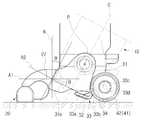
제1 실시예의 업라이트 진공청소기는 청소기 본체(10), 흡입구체(20) 및 조향유닛(30)을 포함한다.The upright vacuum cleaner of the first embodiment includes a cleaner
청소기 본체(10)는, 도 1과 같이, 내측에 흡입력을 제공하기 위한 흡입모터(미도시)와 흡입된 공기로부터 먼지를 분리 및 수거하기 위한 집진장치(미도시)가 설치된다. 또한 청소기 본체(10)는 상측에 조작핸들(11)을 구비하며, 하측에는 양측이 지지하우징(31)에 전후방으로 선회 가능하도록 힌지 결합된다.1, the cleaner
흡입구체(20)는, 도 2와 같이, 청소기 본체(10)의 집진장치(미도시)와 연통되며, 저면에는 피청소면의 먼지를 공기와 함께 흡입하기 위한 흡입구(21)가 형성된다. 또한 흡입구체(20)는 흡입구(21)에 드럼브러시(23)가 회전 가능하게 설치되고, 흡입구(21) 양측에 각각 설치된 한상의 보조휠(25)이 설치된다.As shown in Fig. 2, the
또한 흡입구체(20)는 내측이 흡입구(21)와 연통되고 흡입구체(20) 후방으로 연장 형성되는 가이드 통로(27)가 형성된다. 가이드 통로(27)는 지지하우징(31)의 전방으로 돌출된 연결부(31a)와 상호 축방향으로 선회가능하게 연결된다.The
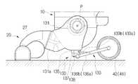
이 경우, 가이드통로(27)와 연결부(31a)가 상호 연결되는 연결면은, 도 3과 같이, 지면에 대한 법선(N)으로부터 지지하우징(31) 측으로 소정 각도(θ) 기울어진 상태로 배치된다. 이에 따라, 회전축(A2)의 축심도 지지하우징(31) 측으로 연결면의 경사각도(θ)와 동일한 각도로 경사를 유지한다. 이러한 경사각도(θ)는 사용자가 청소기 본체(10)를 힌지포인트(P)를 중심으로 후방으로 기울인 상태로 청소를 할 때의 청소기 본체의 경사각도와 평행하거나 유사한 각도 범위 내인 것이 바람직하다. 이는 청소 중 흡입구체(20)의 진행방향을 전환하기 위해 청소기 본체(10)를 후방으로 기울인 상태에서 좌측 또는 우측으로 청소기 본체(10)를 기울일 때, 회전축(A2)과 청소기 본체(10)의 종방향 중심축(C)이 대략 직각을 이루도록 함으로써 지지하우징(31)이 흡입구체(20)에 대하여 원활하게 선회할 수 있도록 하기 위함이다.3, the connecting surface to which the
조향유닛(30)은 청소기 본체(10)와 흡입구체(20) 사이에 설치되며, 지지하우징(31), 스티어링부(33) 및 제1 및 제2 메인휠(41,42)을 포함한다.The
지지하우징(31)은 청소기 본체(10)의 하부를 감싸고, 양측이 각각 청소기 본체(10)와 힌지 결합된다. 이에 따라 청소기 본체(10)는 전후방향으로 힌지포인트(P)를 중심으로 소정 각도 선회한다. 또한 지지하우징(31)은 전방에 흡입구체(20)의 가이드 통로(27)와 축 결합되는 연결부(31a)가 돌출 형성된다. 이 경우, 가이드 통로(27)와 연결부(31a) 내측으로는 플렉시블 호스(미도시) 등이 설치되어 흡입구(21)로부터 유입되는 먼지 및 공기는 가이드 통로(27)와 연결부(31a) 간의 선회 동작에 영향을 받지 않고 집진유닛(미도시)으로 안내된다.The
스티어링부(33)는 청소기 본체(10)의 무게중심이 좌측 또는 우측으로 이동할 경우, 뒤틀림 변형되었다가 다시 청소기 본체(10)를 수직으로 이동할 때 형상이 복원될 수 있도록 소정의 탄성을 갖는 금속재 또는 합성수지재로 이루어진다. 이 경우, 사용자는 스티어링부(33)의 탄성력에 의해 무거운 청소기 본체(10)를 손쉽게 원위치(수직상태)로 이동할 수 있다.When the center of gravity of the cleaner
이러한, 스티어링부(33)는 제1 부분(33a)에서 제2 및 제3 부분(33b,33c)으로 가면서 다단 절곡되며, 전후방향보다 폭방향의 길이가 더 길게 형성된다. 제1 부분(33a)은 중앙이 지지하우징(31) 저부에 고정구(32)에 의해 고정 설치되며 지지하우징(31)의 후방측으로 하향 경사지게 배치된다. 제2 부분(33b)은 제1 부분(33a)의 후단으로부터 연장되며 지지하우징(31)의 후방측으로 상향 경사지게 배치된다. 이 경우 제1 및 제2 부분(33a,33b)은 다수의 지지리브(34)에 의해 절곡 상태를 유지한다. 제3 부분(33c)은 제2 부분(33b)의 후단 양측에 각각 연장 형성되고, 각각 제1 및 제2 메인휠(41,42)이 회전 가능하게 결합되는 샤프트(33d)를 구비한다. 또한 스티어링부(33)의 제1 및 제2 부분(33a,33b)이 절곡 형성함에 따라 제1 및 제2 메인휠(41,42)을 청소기 본체(10)의 후방에 배치할 수 있으므로, 흡입구체(20)와 함께 청소기 본체(10)를 안정적으로 지지할 수 있다.The
한편, 스티어링부(20)는, 도 4와 같이, 지지하우징(31)의 형상에 따라 제1 부분(33a)을 생략하고 제2 및 제3 부분(33b,33c) 만으로 형성하는 것도 물론 가능하다.4, it is also possible to form the
상기와 같이 구성된 본 발명의 제1 실시예에 따른 업라이트 진공청소기의 조향 작동을 첨부된 도 5를 참고하여 설명한다. 도 5는 업라이트 진공청소기를 사용자의 입장에서 우측으로 조정하는 예를 도시한 도면이다. 따라서 이하에 설명하는 청소기 본체(10)의 회전 방향은 사용자의 입장에서 우측방향으로 전환하는 것으로 설명한다.The steering operation of the upright vacuum cleaner according to the first embodiment of the present invention will be described with reference to FIG. 5 is a view showing an example of adjusting the upright vacuum cleaner to the right side from the user's point of view. Therefore, it will be explained that the rotation direction of the cleaner
도 5를 참고하면, 사용자는 청소기 본체(10)의 조작핸들(11)을 파지한 상태에서 청소기 본체(10)를 지지하우징(31)의 힌지포인트(P)를 중심으로 사용자 측으로 소정 각도 기울인 상태로 청소를 행한다.5, when the user grasps the operation handle 11 of the cleaner
이와 같이 청소를 행하는 중에 사용자가 흡입구체(20)의 진행방향을 우측으로 전환하는 경우, 파지한 조작핸들(11)을 우측으로 비틀면 청소기 본체(10)가 회 전축(A2, 도 3 참고)을 중심으로 우측으로 선회하면서 청소기 본체(10)의 무게 중심이 우측으로 이동하게 된다.When the user turns the advancing direction of the
이에 따라, 청소기 본체(10)의 하중이 조향유닛(30)의 스티어링부(33)로 전달되며, 스티어링부(33)가 폭방향으로 비틀림 변형된다. 이 경우, 스티어링부(33)는 흡입구체(20)의 진행방향이 우측으로 설정되도록, 제1 및 제2 메인휠(41,42)이 동시에 우측으로 소정 각도로 기울어진다. 따라서 사용자는 조작핸들(11)을 우측으로 소정 각도로 비틀어주는 간단한 동작만으로 흡입구체(20)의 이동방향을 손쉽게 조정할 수 있다.The load of the cleaner
아울러, 상기와 같이 우측으로 흡입구체(20)의 방향을 전환한 상태에서 , 흡입구체(20)의 진행방향을 다시 직선방향으로 복귀시키는 경우, 조작핸들(11)을 좌측으로 소정각도 비틀어주면 청소기 본체(10)가 회전축(A2)을 중심으로 좌측으로 선회하면서, 비틀림 변형된 상태인 스티어링부(33)에 가해졌던 청소기 본체(10)의 하중이 제거되고 스트어링부(33)가 원형으로 복원되면서 제1 및 제2 메인휠(41,42)은 원위치로 정렬된다. 이 경우, 사용자는 스티어링부(33)의 탄성력에 의해 힘들이지 않고 청소기 본체(10)를 수직으로 원위치 시킬 수 있다.When the
한편, 사용자가 직진방향으로 진행하는 흡입구체(20)의 이동방향을 좌측으로 전환하는 경우도 조작핸들(20)을 좌측으로 비틀어줌에 따라 손쉽게 행할 수 있으며, 이에 대한 자세한 작동설명은 생략한다.On the other hand, even when the user moves the direction of movement of the
첨부된 도 6 내지 도 9를 참고하여, 본 발명의 제2 실시예에 따른 업라이트 청소기의 구성을 상세히 설명한다. 다만, 제2 실시예의 구성 중 제1 실시예의 구성 과 동일한 청소기 본체(10), 흡입구체(20) 및 흡입구체(20)와 지지하우징(131) 간의 관계에 대해서는 설명을 생략하고, 제1 실시예와 상이한 구성을 갖는 조향유닛(130)에 대해서만 설명한다.6 to 9, the configuration of the upright cleaner according to the second embodiment of the present invention will be described in detail. The description of the relationship between the vacuum cleaner
제2 실시예의 조향유닛(130)은 제1 실시예의 조향유닛(30)과 마찬가지로 청소기 본체(10)와 흡입구체(20) 사이에 설치되며, 지지하우징(131), 스티어링부(133) 및 제1 및 제2 메인휠(41,42)을 포함한다.Like the
지지하우징(131)은 청소기 본체(10)의 하부를 감싸고, 양측이 각각 청소기 본체(10)와 힌지 결합된다.The
스티어링부(133)는 고정부(135), 제1 및 제2 메인로드(136a,136b), 회동부(137), 제1 및 제2 서브로드(139a,139b)를 포함한다.The
고정부(135)는 지지하우징(131) 저부의 중심에 돌출된 상태로 고정 결합된다. 제1 및 제2 메인로드(136a,136b)는 일단이 회동부(137) 양측에 각각 결합되고, 타단이 각각 지지하우징(131)의 후방으로 향하도록 배치된다. 이때 도 7과 같이, 제1 및 제2 메인로드(136a,136b)의 타단에는 각각 샤프트(138a,138b)가 설치되고, 상기 샤프트(138a,138b)에는 각각 제1 및 제2 메인휠(41,42)이 회전가능하게 설치된다. 회동부(137)는 중앙이 힌지핀(138)에 의해 상기 고정부(135)의 하측 중앙에 선회가능하게 결합된다. 이 경우, 회동부(137)는 고정부(135)에 힌지 결합되지 않고 지지하우징(131)의 중앙에 직접 힌지 결합되는 것도 물론 가능하다. 더욱이 힌지부(137)는 고정부(135)에 힌지 연결되는 부분에 토션스프링(미도시)을 설치하여 고정부(135)에 대해 탄력적을 선회할 수 있도록 구성하는 것도 물론 가능하 다.The fixing
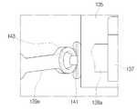
제1 및 제2 서브로드(139a,139b)는 제1 및 제2 메인로드(136a,136b)가 회동부(137)를 중심으로 소정각도 이상으로 선회하는 것을 제한하기 위한 부재로써, 일단이 각각 고정부(135) 양측에 피봇 결합되고, 타단이 각각 제1 및 제2 메인로드(136a,136b)의 대략 중앙부분에 피봇 결합된다. 더욱이 제1 및 제2 서브로드(139a,139b)의 일단은, 도 8과 같이, 볼베어링(143)에 의해 연결된다. 이에 따라 제1 및 제2 메인로드(136a,136b)가 도 9와 같이, 회동부(137)를 중심으로 비틀어지도록 서로 반대방향으로 선회하는 경우, 제1 및 제2 서브로드(139a,139b)는 타단이 고정부(135)에 대하여 다양한 각도로 선회될 수 있다.The first and
상기와 같이 구성된 본 발명의 제2 실시예의 업라이트 진공청소기의 조향작동에 대해 설명하되, 제1 실시예의 동작설명과 같이 흡입구체(20)를 우측으로 선회하는 과정에 대해서만 설명한다.The steering operation of the upright vacuum cleaner according to the second embodiment of the present invention will be described. Only the process of turning the
도 9를 참고하면, 청소 중에 흡입구체(20)의 진행방향을 우측으로 전환하는 경우, 사용자가 파지한 조작핸들(11)을 우측으로 비틀면 청소기 본체(10)는 회전축(A2, 도 3 참고)을 중심으로 우측으로 선회되면서 청소기 본체(10)의 무게 중심이 우측으로 이동된다.9, when the traveling direction of the
이에 따라, 청소기 본체(10)의 하중이 조향유닛(130)의 스티어링부(133)로 전달되며, 스티어링부(133)의 제1 및 제2 메인로드(136a,136b)는 힌지부(137)를 중심으로 서로 반대방향으로 소정각도 선회함에 따라, 힌지부(137)가 좌측으로 선회한다. 이 경우, 제1 및 제2 메인로드(136a,136b)는 제1 및 제2 서브로 드(139a,139b)에 의해 회전 각도가 제한된다. 결국 제1 및 제2 메인휠(41,42)은 우측으로 선회하도록 설정됨에 따라 사용자는 조작핸들(11)을 우측으로 소정 각도로 비틀어주는 간단한 동작만으로 흡입구체(20)의 이동방향을 손쉽게 조정할 수 있다.Accordingly, the load of the cleaner
아울러, 상기와 같이 우측으로 흡입구체(20)의 방향을 전환한 상태에서 흡입구체(20)의 진행방향을 다시 직선방향으로 복귀시키는 경우, 조작핸들(11)을 좌측으로 소정각도 비틀어주면 청소기 본체(10)가 회전축(A2, 도 3 참고)을 중심으로 좌측으로 선회한다. 이에 따라 스티어링부(133)에 가해졌던 청소기 본체(10)의 하중이 제거되면서 제1 및 제2 메인로드(136a,136b)가 서로 반대방향으로 선회하여 회동부(137)가 우측으로 선회한다. 결국, 제1 및 제2 메인로드(136a,136b)가 원위치로 돌아오게 되면 제1 및 제2 메인휠(41,42)은 원위치로 정렬됨에 따라, 사용자는 흡입구체(20)를 직진시킬 수 있게 된다.When the operating
첨부된 도 10 내지 도 12를 참고하여, 본 발명의 제3 실시예에 따른 업라이트 청소기의 구성을 상세히 설명한다. 다만, 제3 실시예의 구성 중 제1 실시예의 구성과 동일한 청소기 본체(10) 및 흡입구체(20)에 대해서는 설명을 생략하고, 제1 실시예와 상이한 구성을 갖는 조향유닛(230)에 대해서만 설명한다.10 to 12, the configuration of the upright cleaner according to the third embodiment of the present invention will be described in detail. However, the description of the same structure of the vacuum cleaner
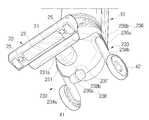
제3 실시예의 조향유닛(230)은 제1 실시예의 조향유닛(30)과 마찬가지로 청소기 본체(10)와 흡입구체(20) 사이에 설치되며, 지지하우징(231), 스티어링부(233), 지지휠(238) 및 제1 및 제2 메인휠(41,42)을 포함한다.Like the
지지하우징(231)은 청소기 본체(10)의 하부를 감싸고, 양측이 각각 청소기 본체(10)와 힌지 결합된다.The
스티어링부(233)는 제1 지지대(234a,234b), 제1 및 제2 댐퍼(235,236)를 포함한다. 제1 및 제2 지지대(234a,234b)는 일단이 각각 지지하우징(231)에 힌지 가능하게 연결되고, 타단이 지지하우징(231)의 후방으로 배치된다. 또한 제1 및 제2 지지대(234a,234b)의 타단에는 각각 제1 및 제2 메인휠(41,42)이 회전 가능하게 결합된다. 제1 및 제2 댐퍼(235,236)는 각각 신축로드(235a,236a) 및 리턴스프링(235b,236b)를 포함한다. 신축로드(235a,236a)는 일단이 각각 지지하우징(231)의 양측에 힌지 결합되고, 타단이 각각 제1 및 제2 지지대(234a,234b)의 대략 중앙 상단에 힌지 결합된다. 이 경우, 신축로드(235a,236a)는 길이가 신축 가능하도록 텔레스코픽 구조로 이루어진다. 리턴스프링(235b,236b)은 신축로드(235a,236a)의 외주에 결합되어 신축로드(235a,236a)의 길이가 축소될 때 복원력을 갖는다.The
한편, 스티어링부(233)은 상기 제1 및 제2 댐퍼(235,236) 대신에 도 13과 같이, 지지하우징(231) 양측에 각각 힌지 결합된 제1 및 제2 지지대(234a,234b) 사이에 토션스프링(335,336)을 설치하여 제1 및 제2 지지대(234a,234b)를 지지하우징(231)에 탄력적으로 설치하는 것도 물론 가능하다.13, the
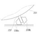
지지휠(238)은 지지하우징(231)의 저부 중앙에 돌출된 지지편(237)에 회전 가능하게 결합된다. 또한 지지휠(238)은 지지편(237)을 중심으로 양측(238a,238b)외주에 각각 테이퍼면이 형성된다. 이는 청소기 본체(10)을 좌측 또는 우측으로 기울였을 때, 도 12와 같이 지지휠(238)의 양측 중 어느 한 측(238a)의 테이퍼면이 지면에 접하면서 제1 및 제2 메인휠(41,42)과 함께 청소기 본체(10)를 안정적으로 지지함과 동시에 피청소면을 원활하게 이동할 수 있도록 하기 위함이다.The
이와 같이 구성된 제3 실시예에 따른 업라이트 진공청소기의 조향작동을 설명하면 다음과 같다.The steering operation of the upright vacuum cleaner according to the third embodiment will be described as follows.
청소 중에 흡입구체(20)의 진행방향을 우측으로 전환하는 경우, 사용자가 파지한 조작핸들(11)을 우측으로 비틀면 청소기 본체(10)는 회전축(A2, 도 3 참고)을 중심으로 우측으로 선회되면서 청소기 본체(10)의 무게 중심이 우측으로 이동된다.When the direction of movement of the
이에 따라, 청소기 본체(10)의 하중이 조향유닛(230)의 스티어링부(233)로 전달되어, 회전하는 측에 배치된 스티어링부(233)의 제1 지지대(234a)가 소정 각도로 선회하고 제2 지지대(234b)는 선회하지 않는다. 이와 동시에 제1 댐퍼(235)의 신축로드(235a)의 길이가 축소되고, 신축로드(235)와 함께 리턴스프링(235b)도 압축되면서 복원력을 갖는다.The load of the cleaner
이에 따라 제1 및 제2 메인휠(41,42)과 지지휠(238)은 모두 우측으로 소정 각도 기울어지도록 설정된다.Accordingly, the first and second
따라서 사용자는 조작핸들(11)을 우측으로 소정 각도로 비틀어주는 간단한 동작만으로 흡입구체(20)의 이동방향을 손쉽게 조정할 수 있다.Therefore, the user can easily adjust the moving direction of the
한편, 상기와 같이 우측으로 흡입구체(20)의 방향을 전환한 상태에서 흡입구체(20)의 진행방향을 다시 직선방향으로 복귀시키는 경우, 조작핸들(11)을 좌측으로 소정각도 비틀어주면 청소기 본체(10)가 회전축(A2, 도 3 참고)을 중심으로 좌측으로 선회한다.On the other hand, in the case of returning the advancing direction of the
이에 따라 스티어링부(233)의 제1 댐퍼(235)에 가해졌던 청소기 본체(10)의 하중이 제거되면서 리턴스프링(235b)의 탄성력에 의해 신축로드(235a)의 길이가 원 래대로 신장되면서 제1 지지대(234a)가 선회하여 원위치로 복귀하게 되고, 동시에, 청소기 본체(10)가 원위치로 복귀하면서 제1 및 제2 메인휠(41,42)은 원위치로 정렬된다. 이에 따라, 사용자는 다시 흡입구체(20)를 직진시킬 수 있게 된다.The load of the cleaner
도 1 및 도 2는 본 발명의 제1 실시예에 따른 업라이트 청소기를 나타내는 사시도,1 and 2 are perspective views showing an upright cleaner according to a first embodiment of the present invention,
도 3은 본 발명의 제1 실시예에 따른 업라이트 청소기를 나타내는 측면도,3 is a side view showing the upright cleaner according to the first embodiment of the present invention,
도 4는 본 발명의 제1 실시예에 따른 업라이트 청소기의 스티어링부의 다른 실시예를 나타내는 측면도,4 is a side view showing another embodiment of the steering unit of the upright cleaner according to the first embodiment of the present invention;
도 5는 본 발명의 제1 실시예에 따른 업라이트 청소기의 사용상태를 나타내는 도면,5 is a view showing a use state of the upright cleaner according to the first embodiment of the present invention,
도 6은 본 발명의 제2 실시예에 따른 업라이트 청소기를 나타내는 측면도,6 is a side view showing the upright cleaner according to the second embodiment of the present invention,
도 7은 본 발명의 제2 실시예에 따른 업라이트 청소기를 나타내는 저면도,7 is a bottom view showing the upright cleaner according to the second embodiment of the present invention,
도 8은 도 7에 도시된 조향유닛의 서브로드의 연결부분을 나타내는 일부 확대사시도,8 is a partially enlarged perspective view showing a connecting portion of the sub-rod of the steering unit shown in Fig. 7,
도 9는 본 발명의 제2 실시예에 따른 업라이트 청소기의 사용상태를 나타내는 도면,9 is a view showing the use state of the upright cleaner according to the second embodiment of the present invention,
도 10은 본 발명의 제2 실시예에 따른 업라이트 청소기를 나타내는 사시도,10 is a perspective view showing an upright cleaner according to a second embodiment of the present invention,
도 11은 도 10에 도시된 조향유닛을 나타내는 일부 확대사시도,11 is a partially enlarged perspective view showing the steering unit shown in Fig. 10, Fig.
도 12는 도 10에 도시된 지지휠을 나타내는 개략도,Fig. 12 is a schematic view showing the support wheel shown in Fig. 10,
도 13은 본 발명의 제3 실시예에 따른 업라이트 청소기의 스티어링부의 다른 실시예를 나타내는 사시도이다.13 is a perspective view showing another embodiment of a steering unit of the upright cleaner according to the third embodiment of the present invention.
*도면 내 주요부분에 대한 부호설명** Explanation of key parts in the drawing *
10: 청소기 본체20: 흡입구체10: Cleaner main body 20: Suction sphere
30, 130, 230: 조향유닛31, 131,231: 지지하우징30, 130, 230:
33, 133, 233: 스티어링부41: 제1 메인휠33, 133, 233: steering portion 41: first main wheel
42: 제2 메인휠42: Second main wheel
Claims (12)
Translated fromKoreanPriority Applications (3)
| Application Number | Priority Date | Filing Date | Title |
|---|---|---|---|
| KR1020080000409AKR101457430B1 (en) | 2008-01-02 | 2008-01-02 | Upright Vacuum Cleaner having Steering Unit |
| US12/154,523US20090165242A1 (en) | 2008-01-02 | 2008-05-23 | Upright vacuum cleaner having steering unit |
| GB0814064AGB2456195B (en) | 2008-01-02 | 2008-07-31 | Upright vacuum cleaner |
Applications Claiming Priority (1)
| Application Number | Priority Date | Filing Date | Title |
|---|---|---|---|
| KR1020080000409AKR101457430B1 (en) | 2008-01-02 | 2008-01-02 | Upright Vacuum Cleaner having Steering Unit |
Publications (2)
| Publication Number | Publication Date |
|---|---|
| KR20090074582A KR20090074582A (en) | 2009-07-07 |
| KR101457430B1true KR101457430B1 (en) | 2014-11-06 |
Family
ID=39767337
Family Applications (1)
| Application Number | Title | Priority Date | Filing Date |
|---|---|---|---|
| KR1020080000409AExpired - Fee RelatedKR101457430B1 (en) | 2008-01-02 | 2008-01-02 | Upright Vacuum Cleaner having Steering Unit |
Country Status (3)
| Country | Link |
|---|---|
| US (1) | US20090165242A1 (en) |
| KR (1) | KR101457430B1 (en) |
| GB (1) | GB2456195B (en) |
Families Citing this family (59)
| Publication number | Priority date | Publication date | Assignee | Title |
|---|---|---|---|---|
| US9301666B2 (en) | 2006-12-12 | 2016-04-05 | Omachron Intellectual Property Inc. | Surface cleaning apparatus |
| US8869344B2 (en) | 2006-12-12 | 2014-10-28 | G.B.D. Corp. | Surface cleaning apparatus with off-centre dirt bin inlet |
| US20210401246A1 (en) | 2016-04-11 | 2021-12-30 | Omachron Intellectual Property Inc. | Surface cleaning apparatus |
| US12048409B2 (en) | 2007-03-11 | 2024-07-30 | Omachron Intellectual Property Inc. | Portable surface cleaning apparatus |
| US11751733B2 (en) | 2007-08-29 | 2023-09-12 | Omachron Intellectual Property Inc. | Portable surface cleaning apparatus |
| US9591952B2 (en) | 2009-03-11 | 2017-03-14 | Omachron Intellectual Property Inc. | Hand vacuum cleaner with removable dirt chamber |
| US10722086B2 (en) | 2017-07-06 | 2020-07-28 | Omachron Intellectual Property Inc. | Handheld surface cleaning apparatus |
| US11690489B2 (en) | 2009-03-13 | 2023-07-04 | Omachron Intellectual Property Inc. | Surface cleaning apparatus with an external dirt chamber |
| CA2967272C (en) | 2009-03-13 | 2018-01-02 | Omachron Intellectual Property Inc. | Hand vacuum cleaner |
| GB2474466B (en)* | 2009-10-15 | 2014-03-05 | Dyson Technology Ltd | A surface treating appliance |
| GB2474473B (en)* | 2009-10-15 | 2013-10-23 | Dyson Technology Ltd | A surface treating appliance |
| GB0918027D0 (en)* | 2009-10-15 | 2009-12-02 | Dyson Technology Ltd | A surface trating appliance |
| GB2474463B (en)* | 2009-10-15 | 2013-11-13 | Dyson Technology Ltd | A surface treating appliance |
| GB2474470B (en)* | 2009-10-15 | 2013-10-23 | Dyson Technology Ltd | A surface treating appliance |
| GB2474472B (en)* | 2009-10-15 | 2013-10-23 | Dyson Technology Ltd | A surface treating appliance |
| GB2474465B (en)* | 2009-10-15 | 2013-10-23 | Dyson Technology Ltd | A surface treating appliance |
| GB2474464B (en)* | 2009-10-15 | 2013-11-20 | Dyson Technology Ltd | A surface treating appliance |
| GB2474462B (en)* | 2009-10-15 | 2013-12-11 | Dyson Technology Ltd | A surface treating appliance with domed-shaped wheels |
| GB2474475B (en)* | 2009-10-15 | 2013-10-23 | Dyson Technology Ltd | A surface treating appliance |
| GB2474469B (en)* | 2009-10-15 | 2013-11-13 | Dyson Technology Ltd | A surface treating appliance |
| US8082624B2 (en) | 2009-11-10 | 2011-12-27 | Oreck Holdings Llc | Rotatable coupling for steering vacuum cleaner |
| WO2011099653A1 (en)* | 2010-02-09 | 2011-08-18 | 엘지전자 주식회사 | Upright vacuum cleaner |
| KR101187077B1 (en)* | 2010-08-09 | 2012-09-27 | 엘지전자 주식회사 | Upright type vacuum cleaner |
| US8667643B2 (en) | 2010-09-10 | 2014-03-11 | Euro-Pro Operating Llc | Method and apparatus for assisting pivot motion of a handle in a floor treatment device |
| KR101291202B1 (en)* | 2010-09-30 | 2013-07-31 | 삼성전자주식회사 | Upright Vacuum Cleaner |
| GB2484146B (en) | 2010-10-01 | 2013-02-13 | Dyson Technology Ltd | A vacuum cleaner |
| US8869349B2 (en) | 2010-10-15 | 2014-10-28 | Techtronic Floor Care Technology Limited | Steering assembly for surface cleaning device |
| GB2485401B (en)* | 2010-11-15 | 2015-04-01 | Hoover Ltd | Locking coupling for a vacuum cleaner |
| KR101227517B1 (en) | 2011-01-18 | 2013-01-31 | 엘지전자 주식회사 | Upright type vacuum cleaner |
| US8627545B2 (en)* | 2011-03-18 | 2014-01-14 | Panasonic Corporation Of North America | Vacuum cleaner with enhanced maneuverability |
| KR101314678B1 (en)* | 2011-08-18 | 2013-10-07 | 엘지전자 주식회사 | Cleaner with steering means for head |
| WO2013055364A1 (en)* | 2011-10-14 | 2013-04-18 | Techtronic Floor Care Technology Limited | Steering assembly for surface cleaning device |
| US9282862B2 (en)* | 2011-10-14 | 2016-03-15 | Techtronic Floor Care Technology Limited | Steering assembly for surface cleaning device |
| KR101342386B1 (en)* | 2012-03-06 | 2013-12-16 | 엘지전자 주식회사 | Upright type vacuum cleaner |
| CN104271020B (en)* | 2012-03-19 | 2017-04-05 | 伊莱克斯公司 | Upright vacuum cleaner with support member |
| KR102083800B1 (en)* | 2013-06-12 | 2020-03-03 | 삼성전자주식회사 | Vacuum cleaner |
| KR101661028B1 (en) | 2014-10-22 | 2016-10-10 | 엘지전자 주식회사 | Vacuum cleaner |
| CN206026220U (en)* | 2015-06-17 | 2017-03-22 | 碧洁家庭护理有限公司 | Vacuum cleaner |
| US9357891B1 (en)* | 2015-08-04 | 2016-06-07 | Richard C. Chappel | Cleaning apparatus holder |
| US9961838B2 (en) | 2015-11-23 | 2018-05-08 | Corey Andri HORTH | Lawn debris collection assembly |
| US11918170B2 (en) | 2016-04-11 | 2024-03-05 | Omachron Intellectual Property Inc. | Surface cleaning apparatus |
| US10258210B2 (en) | 2016-12-27 | 2019-04-16 | Omachron Intellectual Property Inc. | Multistage cyclone and surface cleaning apparatus having same |
| KR102504105B1 (en)* | 2016-05-12 | 2023-02-28 | 삼성전자주식회사 | Vacuum cleaner |
| US10271704B2 (en) | 2016-12-27 | 2019-04-30 | Omachron Intellectual Property Inc. | Multistage cyclone and surface cleaning apparatus having same |
| US11285495B2 (en) | 2016-12-27 | 2022-03-29 | Omachron Intellectual Property Inc. | Multistage cyclone and surface cleaning apparatus having same |
| US10016106B1 (en) | 2016-12-27 | 2018-07-10 | Omachron Intellectual Property Inc. | Multistage cyclone and surface cleaning apparatus having same |
| US10827891B2 (en) | 2016-12-27 | 2020-11-10 | Omachron Intellectual Property Inc. | Multistage cyclone and surface cleaning apparatus having same |
| US10405709B2 (en) | 2016-12-27 | 2019-09-10 | Omachron Intellectual Property Inc. | Multistage cyclone and surface cleaning apparatus having same |
| US10299643B2 (en) | 2016-12-27 | 2019-05-28 | Omachron Intellectual Property Inc. | Multistage cyclone and surface cleaning apparatus having same |
| US11745190B2 (en) | 2019-01-23 | 2023-09-05 | Omachron Intellectual Property Inc. | Surface cleaning apparatus |
| US10575701B2 (en) | 2017-09-15 | 2020-03-03 | Omachron Intellectual Property Inc. | Surface cleaning apparatus |
| GB2586193B (en) | 2018-04-23 | 2021-09-15 | Sharkninja Operating Llc | Assisted drive for surface cleaning devices |
| EP3790436B1 (en) | 2018-05-09 | 2023-07-19 | SharkNinja Operating LLC | Upright vacuum cleaner including main body moving independently of wand to reduce movement of main body center of gravity |
| GB2589774B (en) | 2018-07-02 | 2022-11-30 | Sharkninja Operating Llc | Vacuum pod configured to couple to one or more accessories |
| WO2020051433A1 (en) | 2018-09-07 | 2020-03-12 | Sharkninja Operating Llc | Battery and suction motor assembly for a surface treatment apparatus and a surface treatment apparatus having the same |
| JP7200362B2 (en) | 2018-09-19 | 2023-01-06 | シャークニンジャ オペレーティング エルエルシー | Cleaning head for surface treatment apparatus having one or more stabilizers and surface treatment apparatus having the same |
| CN110448220B (en)* | 2019-08-28 | 2024-06-21 | 苏州市春菊电器有限公司 | Floor brush and dust collector with same |
| US11246462B2 (en) | 2019-11-18 | 2022-02-15 | Omachron Intellectual Property Inc. | Multi-inlet cyclone |
| US11751740B2 (en) | 2019-11-18 | 2023-09-12 | Omachron Intellectual Property Inc. | Multi-inlet cyclone |
Citations (4)
| Publication number | Priority date | Publication date | Assignee | Title |
|---|---|---|---|---|
| US5323510A (en)* | 1993-07-09 | 1994-06-28 | Redding Glenn K | Vacuum cleaner having improved steering features |
| JPH10328086A (en)* | 1998-03-03 | 1998-12-15 | Hitachi Ltd | Vacuum cleaner mouthpiece |
| KR20060004647A (en)* | 2002-08-09 | 2006-01-12 | 다이슨 테크놀러지 리미티드 | Surface treating appliance |
| GB2433425A (en)* | 2005-12-23 | 2007-06-27 | Cassidy Brothers Plc | A vacuum cleaner |
Family Cites Families (3)
| Publication number | Priority date | Publication date | Assignee | Title |
|---|---|---|---|---|
| US6055703A (en)* | 1997-10-14 | 2000-05-02 | Oreck Holdings Llc | Upright vacuum cleaner having improved steering apparatus with a lock out feature |
| US7805804B2 (en)* | 2004-12-21 | 2010-10-05 | Royal Appliance Mfg. Co. | Steerable upright vacuum cleaner |
| KR101390924B1 (en)* | 2007-10-08 | 2014-05-07 | 삼성전자주식회사 | Upright Vacuum Cleaner having Steering Unit |
- 2008
- 2008-01-02KRKR1020080000409Apatent/KR101457430B1/ennot_activeExpired - Fee Related
- 2008-05-23USUS12/154,523patent/US20090165242A1/ennot_activeAbandoned
- 2008-07-31GBGB0814064Apatent/GB2456195B/ennot_activeExpired - Fee Related
Patent Citations (4)
| Publication number | Priority date | Publication date | Assignee | Title |
|---|---|---|---|---|
| US5323510A (en)* | 1993-07-09 | 1994-06-28 | Redding Glenn K | Vacuum cleaner having improved steering features |
| JPH10328086A (en)* | 1998-03-03 | 1998-12-15 | Hitachi Ltd | Vacuum cleaner mouthpiece |
| KR20060004647A (en)* | 2002-08-09 | 2006-01-12 | 다이슨 테크놀러지 리미티드 | Surface treating appliance |
| GB2433425A (en)* | 2005-12-23 | 2007-06-27 | Cassidy Brothers Plc | A vacuum cleaner |
Also Published As
| Publication number | Publication date |
|---|---|
| KR20090074582A (en) | 2009-07-07 |
| US20090165242A1 (en) | 2009-07-02 |
| GB0814064D0 (en) | 2008-09-10 |
| GB2456195A (en) | 2009-07-08 |
| GB2456195B (en) | 2010-03-03 |
Similar Documents
| Publication | Publication Date | Title |
|---|---|---|
| KR101457430B1 (en) | Upright Vacuum Cleaner having Steering Unit | |
| KR101390924B1 (en) | Upright Vacuum Cleaner having Steering Unit | |
| CN1953691B (en) | Attachment for a cleaning appliance | |
| CN112334050B (en) | Vacuum cleaner, upright vacuum cleaner and multi-axis pivot joint | |
| JP4961008B2 (en) | Floor tools for vacuum cleaners | |
| CN101511247B (en) | Support components | |
| JP6108745B2 (en) | Floor wiping device and main body driven to swing relative to fixed part | |
| JP6229169B2 (en) | Vacuum cleaner suction tool and vacuum cleaner provided with the same | |
| US20130086768A1 (en) | Upright floor surface treating apparatus | |
| JP6032459B2 (en) | Vacuum cleaner suction tool and vacuum cleaner provided with the same | |
| KR20220112425A (en) | Cleaner | |
| US9060662B2 (en) | Upright type vacuum cleaner | |
| CN1390104A (en) | Casters for buffer structures of vacuum cleaners | |
| US20060005349A1 (en) | Vacuum cleaner height adjustment | |
| KR20010035934A (en) | Upright type vacuum cleaner | |
| TWI825624B (en) | Cleaner | |
| CN102258349A (en) | Vacuum cleaner | |
| JP4407048B2 (en) | Suction port for vacuum cleaner and electric vacuum cleaner using the same | |
| US8720003B2 (en) | Upright type vacuum cleaner | |
| KR20230086156A (en) | Cleaner |
Legal Events
| Date | Code | Title | Description |
|---|---|---|---|
| PA0109 | Patent application | St.27 status event code:A-0-1-A10-A12-nap-PA0109 | |
| PG1501 | Laying open of application | St.27 status event code:A-1-1-Q10-Q12-nap-PG1501 | |
| N231 | Notification of change of applicant | ||
| PN2301 | Change of applicant | St.27 status event code:A-3-3-R10-R13-asn-PN2301 St.27 status event code:A-3-3-R10-R11-asn-PN2301 | |
| R18-X000 | Changes to party contact information recorded | St.27 status event code:A-3-3-R10-R18-oth-X000 | |
| A201 | Request for examination | ||
| PA0201 | Request for examination | St.27 status event code:A-1-2-D10-D11-exm-PA0201 | |
| D13-X000 | Search requested | St.27 status event code:A-1-2-D10-D13-srh-X000 | |
| D14-X000 | Search report completed | St.27 status event code:A-1-2-D10-D14-srh-X000 | |
| E902 | Notification of reason for refusal | ||
| PE0902 | Notice of grounds for rejection | St.27 status event code:A-1-2-D10-D21-exm-PE0902 | |
| E13-X000 | Pre-grant limitation requested | St.27 status event code:A-2-3-E10-E13-lim-X000 | |
| P11-X000 | Amendment of application requested | St.27 status event code:A-2-2-P10-P11-nap-X000 | |
| P13-X000 | Application amended | St.27 status event code:A-2-2-P10-P13-nap-X000 | |
| PE0701 | Decision of registration | St.27 status event code:A-1-2-D10-D22-exm-PE0701 | |
| GRNT | Written decision to grant | ||
| PR0701 | Registration of establishment | St.27 status event code:A-2-4-F10-F11-exm-PR0701 | |
| PR1002 | Payment of registration fee | St.27 status event code:A-2-2-U10-U11-oth-PR1002 Fee payment year number:1 | |
| PG1601 | Publication of registration | St.27 status event code:A-4-4-Q10-Q13-nap-PG1601 | |
| LAPS | Lapse due to unpaid annual fee | ||
| PC1903 | Unpaid annual fee | St.27 status event code:A-4-4-U10-U13-oth-PC1903 Not in force date:20171029 Payment event data comment text:Termination Category : DEFAULT_OF_REGISTRATION_FEE | |
| PC1903 | Unpaid annual fee | St.27 status event code:N-4-6-H10-H13-oth-PC1903 Ip right cessation event data comment text:Termination Category : DEFAULT_OF_REGISTRATION_FEE Not in force date:20171029 |