KR101456735B1 - Middle or large sized battery pack and packaging method thereof - Google Patents
Middle or large sized battery pack and packaging method thereofDownload PDFInfo
- Publication number
- KR101456735B1 KR101456735B1KR1020100027261AKR20100027261AKR101456735B1KR 101456735 B1KR101456735 B1KR 101456735B1KR 1020100027261 AKR1020100027261 AKR 1020100027261AKR 20100027261 AKR20100027261 AKR 20100027261AKR 101456735 B1KR101456735 B1KR 101456735B1
- Authority
- KR
- South Korea
- Prior art keywords
- packaging
- packaging material
- battery pack
- packaged
- unit
- Prior art date
- Legal status (The legal status is an assumption and is not a legal conclusion. Google has not performed a legal analysis and makes no representation as to the accuracy of the status listed.)
- Active
Links
Images


Classifications
- H—ELECTRICITY
- H01—ELECTRIC ELEMENTS
- H01M—PROCESSES OR MEANS, e.g. BATTERIES, FOR THE DIRECT CONVERSION OF CHEMICAL ENERGY INTO ELECTRICAL ENERGY
- H01M50/00—Constructional details or processes of manufacture of the non-active parts of electrochemical cells other than fuel cells, e.g. hybrid cells
- H01M50/20—Mountings; Secondary casings or frames; Racks, modules or packs; Suspension devices; Shock absorbers; Transport or carrying devices; Holders
- H—ELECTRICITY
- H01—ELECTRIC ELEMENTS
- H01M—PROCESSES OR MEANS, e.g. BATTERIES, FOR THE DIRECT CONVERSION OF CHEMICAL ENERGY INTO ELECTRICAL ENERGY
- H01M10/00—Secondary cells; Manufacture thereof
- H01M10/05—Accumulators with non-aqueous electrolyte
- H01M10/052—Li-accumulators
- H—ELECTRICITY
- H01—ELECTRIC ELEMENTS
- H01M—PROCESSES OR MEANS, e.g. BATTERIES, FOR THE DIRECT CONVERSION OF CHEMICAL ENERGY INTO ELECTRICAL ENERGY
- H01M50/00—Constructional details or processes of manufacture of the non-active parts of electrochemical cells other than fuel cells, e.g. hybrid cells
- H01M50/10—Primary casings; Jackets or wrappings
- H01M50/116—Primary casings; Jackets or wrappings characterised by the material
- H01M50/124—Primary casings; Jackets or wrappings characterised by the material having a layered structure
- H—ELECTRICITY
- H01—ELECTRIC ELEMENTS
- H01M—PROCESSES OR MEANS, e.g. BATTERIES, FOR THE DIRECT CONVERSION OF CHEMICAL ENERGY INTO ELECTRICAL ENERGY
- H01M50/00—Constructional details or processes of manufacture of the non-active parts of electrochemical cells other than fuel cells, e.g. hybrid cells
- H01M50/30—Arrangements for facilitating escape of gases
- H01M50/342—Non-re-sealable arrangements
- H01M50/3425—Non-re-sealable arrangements in the form of rupturable membranes or weakened parts, e.g. pierced with the aid of a sharp member
- H—ELECTRICITY
- H01—ELECTRIC ELEMENTS
- H01M—PROCESSES OR MEANS, e.g. BATTERIES, FOR THE DIRECT CONVERSION OF CHEMICAL ENERGY INTO ELECTRICAL ENERGY
- H01M50/00—Constructional details or processes of manufacture of the non-active parts of electrochemical cells other than fuel cells, e.g. hybrid cells
- H01M50/50—Current conducting connections for cells or batteries
- H01M50/531—Electrode connections inside a battery casing
- H—ELECTRICITY
- H01—ELECTRIC ELEMENTS
- H01M—PROCESSES OR MEANS, e.g. BATTERIES, FOR THE DIRECT CONVERSION OF CHEMICAL ENERGY INTO ELECTRICAL ENERGY
- H01M50/00—Constructional details or processes of manufacture of the non-active parts of electrochemical cells other than fuel cells, e.g. hybrid cells
- H01M50/50—Current conducting connections for cells or batteries
- H01M50/543—Terminals
- H—ELECTRICITY
- H01—ELECTRIC ELEMENTS
- H01M—PROCESSES OR MEANS, e.g. BATTERIES, FOR THE DIRECT CONVERSION OF CHEMICAL ENERGY INTO ELECTRICAL ENERGY
- H01M2200/00—Safety devices for primary or secondary batteries
- H01M2200/20—Pressure-sensitive devices
- H—ELECTRICITY
- H01—ELECTRIC ELEMENTS
- H01M—PROCESSES OR MEANS, e.g. BATTERIES, FOR THE DIRECT CONVERSION OF CHEMICAL ENERGY INTO ELECTRICAL ENERGY
- H01M2220/00—Batteries for particular applications
- H01M2220/20—Batteries in motive systems, e.g. vehicle, ship, plane
- Y—GENERAL TAGGING OF NEW TECHNOLOGICAL DEVELOPMENTS; GENERAL TAGGING OF CROSS-SECTIONAL TECHNOLOGIES SPANNING OVER SEVERAL SECTIONS OF THE IPC; TECHNICAL SUBJECTS COVERED BY FORMER USPC CROSS-REFERENCE ART COLLECTIONS [XRACs] AND DIGESTS
- Y02—TECHNOLOGIES OR APPLICATIONS FOR MITIGATION OR ADAPTATION AGAINST CLIMATE CHANGE
- Y02E—REDUCTION OF GREENHOUSE GAS [GHG] EMISSIONS, RELATED TO ENERGY GENERATION, TRANSMISSION OR DISTRIBUTION
- Y02E60/00—Enabling technologies; Technologies with a potential or indirect contribution to GHG emissions mitigation
- Y02E60/10—Energy storage using batteries
- Y—GENERAL TAGGING OF NEW TECHNOLOGICAL DEVELOPMENTS; GENERAL TAGGING OF CROSS-SECTIONAL TECHNOLOGIES SPANNING OVER SEVERAL SECTIONS OF THE IPC; TECHNICAL SUBJECTS COVERED BY FORMER USPC CROSS-REFERENCE ART COLLECTIONS [XRACs] AND DIGESTS
- Y02—TECHNOLOGIES OR APPLICATIONS FOR MITIGATION OR ADAPTATION AGAINST CLIMATE CHANGE
- Y02P—CLIMATE CHANGE MITIGATION TECHNOLOGIES IN THE PRODUCTION OR PROCESSING OF GOODS
- Y02P70/00—Climate change mitigation technologies in the production process for final industrial or consumer products
- Y02P70/50—Manufacturing or production processes characterised by the final manufactured product
- Y—GENERAL TAGGING OF NEW TECHNOLOGICAL DEVELOPMENTS; GENERAL TAGGING OF CROSS-SECTIONAL TECHNOLOGIES SPANNING OVER SEVERAL SECTIONS OF THE IPC; TECHNICAL SUBJECTS COVERED BY FORMER USPC CROSS-REFERENCE ART COLLECTIONS [XRACs] AND DIGESTS
- Y02—TECHNOLOGIES OR APPLICATIONS FOR MITIGATION OR ADAPTATION AGAINST CLIMATE CHANGE
- Y02T—CLIMATE CHANGE MITIGATION TECHNOLOGIES RELATED TO TRANSPORTATION
- Y02T10/00—Road transport of goods or passengers
- Y02T10/60—Other road transportation technologies with climate change mitigation effect
- Y02T10/70—Energy storage systems for electromobility, e.g. batteries
Landscapes
- Chemical & Material Sciences (AREA)
- Chemical Kinetics & Catalysis (AREA)
- Electrochemistry (AREA)
- General Chemical & Material Sciences (AREA)
- Engineering & Computer Science (AREA)
- Manufacturing & Machinery (AREA)
- Sealing Battery Cases Or Jackets (AREA)
- Battery Mounting, Suspending (AREA)
Abstract
Translated fromKoreanDescription
Translated fromKorean본 발명은 안전성 및 공간활용도가 개선된 중대형 전지팩 및 그 패키징 방법에 대한 것으로서, 보다 상세하게는 전지셀을 파우치형 포장재로 1차 패키징하고 상기 1차 패키징된 다수의 전지셀을 결합하여 금속관 또는 플라스틱 관 및 바로 팩조립이 가능한 재질로 2차 패키징하여 이들을 모듈 케이스에 효율적으로 배치함으로써, 안전성 및 공간활용도가 개선된 중대형 전지팩 및 그 패키징방법에 관한 것이다.
The present invention relates to a middle- or large-sized battery pack having improved safety and space utilization, and a packaging method thereof. More particularly, the present invention relates to a middle- or large- To a middle- or large-sized battery pack having improved safety and space utilization by efficiently packaging a secondary battery with a plastic tube and a material capable of assembling the battery pack into a module case, and a packaging method therefor.
최근, 충방전이 가능한 리튬이차전지는 와이어리스 모바일 기기의 에너지원으로 광범위하게 사용되고 있으며 또한, 화석 연료를 사용하던 기존의 가솔린 차량, 디젤 차량 등의 대기오염 등을 해결하기 위한 방안으로 제시되고 있는 전기자동차, 하이브리드 전기자동차(HEV) 등의 동력원으로도 주목받고 있다.In recent years, lithium secondary batteries, which can be charged and discharged, have been widely used as energy sources for wireless mobile devices. Also, they are being used as a means of solving air pollution in existing gasoline vehicles and diesel vehicles using fossil fuels. Automobiles, and hybrid electric vehicles (HEVs).
특히, 전기 자동차 등과 같은 중대형 디바이스들은 고출력 대용량의 필요성으로 인해 다수의 전지 셀을 전기적으로 연결한 중대형 전지 시스템이 사용되며, 요구되는 출력량 및 에너지 밀도가 점차 높아짐에 따라 중대형 이차 전지에 포함되는 단위모듈의 수가 점차 증가하게 된다.Particularly, middle- or large-sized devices such as electric vehicles use middle- or large-sized battery systems in which a large number of battery cells are electrically connected due to the necessity of a high output large capacity. As a required output amount and energy density are gradually increased, Is gradually increased.
이러한 중대형 전지 시스템에 단위전지로서 많이 사용되는 파우치형 리튬이온 폴리머 이차전지는 소형 디바이스에 사용되는 동일 계열의 전지에 비해 상대적으로 큰 크기를 가지고 있다. 또한, 전기 자동차, plug-in 및 hybrid 자동차 등의 전원으로 사용되는 중대형의 리튬 이차전지의 팩 설계 시에는 높은 출력 뿐만 아니라 높은 에너지 또한 고려하여야 하기 때문에 이를 위해서는 한정된 스페이스에 큰 용량의 전지가 탑재되어야 하며, 이를 위해 현재는 많은 수의 단위 셀들을 하나의 리튬이차전지 내에 패키징하여 사용해야 하는바, 하나의 배터리에 점차 포함되는 단위셀의 개수가 늘어나거나 셀의 크기가 매우 커지게 된다.The pouch-type lithium ion polymer secondary battery, which is often used as a unit cell in such a middle- or large-sized battery system, has a relatively large size as compared with a battery of the same type used in a small-sized device. Also, when designing a pack for a medium-sized lithium secondary battery used as a power source for an electric vehicle, a plug-in, and a hybrid vehicle, a high capacity as well as a high output power must be considered. For this purpose, a large number of unit cells are currently used in a single lithium rechargeable battery, so that the number of unit cells gradually increases in one battery or the cell size becomes very large.
따라서 중대형 디바이스의 전원으로 사용되는 리튬 이차 전지의 경우 그 패키징 공정이 복잡해지는 것은 물론 패키징의 두께도 늘어나게 되어 결과적으로 제조 공정상의 어려움과 성능 감소 및 공간의 효율성 감소등으로 인해 리튬 이차 전지의 효과가 저하되는 문제 등이 발생할 우려가 있다.Therefore, in the case of a lithium secondary battery used as a power source for medium to large-sized devices, the packaging process is complicated and the thickness of the packaging is increased. As a result, the effect of the lithium secondary battery is reduced due to difficulties in the manufacturing process, There is a possibility that a problem of degradation may occur.
따라서 대용량의 전지팩을 만들기 위한 셀 패키징 방법에 있어서, 간편하면서도 효율적인 리튬이차전지의 패키징 방식에 대한 연구의 필요성이 높아지고 있는 것이 현실이다.
Therefore, in a cell packaging method for making a battery pack of a large capacity, there is a real need for a simple and efficient research on a packaging method of a lithium secondary battery.
본 발명은 상기와 같은 문제점을 해결하기 위하여 안출된 것으로, 하이브리드 및 전기 자동차 등의 전원으로 이용되는 중대형 전지팩을 제조하는데 있어서 다수의 전지셀 및 단위모듈을 간단하게 패키징 할 수 있으면서도 기존 셀 패키징 재료들의 장점을 모두 유지함은 물론, 팩 조립시 내부 공간의 활용도를 극대화하여, 안전성이 더욱 개선된 고용량의 중대형 전지팩 및 그 패키징 방법을 제공한다.
SUMMARY OF THE INVENTION The present invention has been conceived to solve the above-mentioned problems, and it is an object of the present invention to provide a battery pack for a battery pack, which can easily package a plurality of battery cells and unit modules, Sized battery pack and a method for packaging the same, which maximize the utilization of the internal space at the time of assembling the pack and have improved safety.
상기와 같은 과제를 해결하기 위하여 본 발명은 다음과 같은 수단을 이용한다.In order to solve the above problems, the present invention uses the following means.
본 발명은, 리튬 이차전지 팩의 패키징 방법에 있어서,The present invention relates to a method of packaging a lithium secondary battery pack,
전극조립체 및 전해액을 포함하는 전지셀을 1차 패키징하는 제1 단계;A first step of firstly packaging a battery cell including an electrode assembly and an electrolyte;
상기 1차 패키징 된 다수의 전지셀을 적층한 단위모듈의 바디(body) 부분을 2차 패키징하는 제2 단계;A second step of secondary packaging the body part of the unit module in which the plurality of primary cells are laminated;
상기 단위모듈의 상단면 및 하단면을 패키징하는 3 단계; 및Packaging the top and bottom surfaces of the unit module; And
상기 3단계에 의한 단위모듈을 모듈 케이스에 배열하는 4 단계로 이루어진 이루어진 리튬 이차전지 팩의 패키징방법을 제공한다.And arranging the unit module according to the above three steps in a module case. The present invention also provides a method of packaging a lithium secondary battery pack.
상기 1 단계의 1차 패키징을 위한 포장재는 전해액에 용해되지 않는 열가소성 수지만으로 이루어진 파우치형 포장재를 이용하여 패키징하는 것을 특징으로 한다.The packaging material for the first-stage packaging in the first stage is characterized by packaging using a pouch-type packaging material made only of a thermoplastic resin which is not dissolved in the electrolyte solution.
상기 전해액에 용해되지 않는 열가소성 수지는 PE(폴리에틸렌), PP(폴리 프로필렌), PS(폴리스틸렌), PVC(염화비닐), nylon(폴리아미드), PET (폴리에틸렌테레프탈레이트)로 이루어진 군에서 선택된 어느 하나인 것을 특징으로 한다.The thermoplastic resin which is not soluble in the electrolytic solution may be any one selected from the group consisting of PE (polyethylene), PP (polypropylene), PS (polystyrene), PVC (vinyl chloride), nylon (polyamide), and PET (polyethylene terephthalate) .
상기 1 단계의 1차 패키징을 위한 포장재는 금속 라미네이트층이 내장되어 있고 상기 금속라미네이트층의 외부는 전해액에 용해되지 않는 열가소성 수지로 이루어진 파우치형 포장재인 것을 특징으로 한다.The packaging material for the first-stage packaging in the first step is a pouch-type packaging material which is formed of a thermoplastic resin having a metal laminate layer embedded therein and the outside of the metal laminate layer is not dissolved in an electrolyte solution.
상기 금속 라미네이트층은 알루미늄 금속라미네이트층인 것을 특징으로 한다.Wherein the metal laminate layer is an aluminum metal laminate layer.
또한, 상기 제2단계의 2차 패키징은, 상단면 및 하단면에 상응하는 양 끝단면이 개방된 플라스틱관 또는 금속관으로 패키징하는 것을 특징으로 한다. 상기 플라스틱 관은 PE(폴리에틸렌), PP(폴리 프로필렌), PS(폴리스틸렌), PVC(염화비닐), 아크릴 수지로 이루어진 군에서 선택되는 어느 하나로 이루어진 것을 특징으로 하며, 상기 금속관은 알루미늄, 철, 니켈, 구리 또는 이들의 합금으로 이루어진 군에서 선택되는 어느 하나로 이루어진 것을 특징으로 한다.The secondary packaging in the second step is characterized by packaging with a plastic tube or a metal tube having open end surfaces corresponding to the top and bottom surfaces. Wherein the plastic tube is made of any one selected from the group consisting of PE (polyethylene), PP (polypropylene), PS (polystyrene), PVC (vinyl chloride), acrylic resin, , Copper, or an alloy thereof.
상기 3 단계에 의한 단위모듈의 상단면 또는 하단면을 패키징하기 위한 포장재는, 보호회로 또는 PTC회로인 것을 특징으로 한다.The packaging material for packaging the upper or lower surface of the unit module according to the above three steps is a protection circuit or a PTC circuit.
상기 보호회로 또는 PTC회로의 면적은, 상기 플라스틱관 또는 금속관의 단면의 크기와 같거나 또는 0.2mm내지 2cm만큼 더 큰 것을 특징으로 한다.The area of the protection circuit or the PTC circuit is equal to the size of the cross section of the plastic pipe or the metal pipe or is larger by 0.2 mm to 2 cm.
상기4 단계는, 단위 모듈의 상단면 또는 하단면에 부착된 보호회로 또는 PTC 회로가 모듈 케이스의 바닥면에 닿도록 단위모듈을 수직 배열하는 것을 특징으로 한다.The fourth step is characterized in that the unit modules are arranged vertically such that the protection circuit or the PTC circuit attached to the upper surface or the lower surface of the unit module touches the bottom surface of the module case.
상기 단위 모듈은 전극리드가 동일한 방향에 위치되어 있는 것을 특징으로 한다.And the unit module is characterized in that the electrode leads are positioned in the same direction.
또한, 상기 단위 모듈은 모듈 케이스내에 직렬 또는 병렬로 적층 또는 나열되는 것을 특징으로 한다.The unit modules are stacked or arranged in series or in parallel in the module case.
본 발명은 또한,The present invention also relates to
전극조립체 및 전해액을 포함하여 1차 포장재로 패키징 된 전지셀;A battery cell packaged with a primary packaging material including an electrode assembly and an electrolyte;
상기 전지셀을 적층하고 바디(body) 부분을 2차 포장재로 패키징한 후 전극탭이 위치한 면의 반대되는 하단면은 보호회로 또는 PTC 회로로 패키징하고 전극탭이 위치한 상단면은 캡 어셈블리로 패키징한 단위 모듈; 및 상기 단위모듈이 복수개 포함되어 있는 모듈 케이스; 를 포함하고 있는 중대형 전지팩을 제공한다.The battery cell is stacked and the body part is packaged with the secondary packaging material. The opposite lower end surface of the surface on which the electrode tab is located is packaged by a protection circuit or a PTC circuit, and the upper surface where the electrode tab is located is packaged by a cap assembly Unit module; A module case including a plurality of unit modules; And a battery pack.
상기 1 차 포장재는 전해액에 용해되지 않는 열가소성 수지만으로 이루어진 파우치형 포장재인 것을 특징으로 하고, 상기 전해액에 용해되지 않는 열가소성 수지는 PE(폴리에틸렌), PP(폴리 프로필렌), PS(폴리스틸렌), PVC(염화비닐), nylon(폴리아미드), PET (폴리에틸렌테레프탈레이트)로 이루어진 군에서 선택된 어느 하나인 것을 특징으로 한다.The primary packaging material is a pouch-type packaging material made only of a thermoplastic resin that is not dissolved in an electrolyte. The thermoplastic resin that is not soluble in the electrolyte is selected from the group consisting of PE (polyethylene), PP (polypropylene) (Vinyl chloride), nylon (polyamide), and PET (polyethylene terephthalate).
상기 1차 포장재는 금속 라미네이트층이 내장되어 있고, 상기 금속라미네이트층의 외부는 전해액에 용해되지 않는 열가소성 수지로 이루어진 파우치형 포장재인 것을 특징으로 하며, 상기 금속 라미네이트층은 알루미늄 금속라미네이트층인 것을 특징으로 한다.Wherein the primary packaging material is a pouch-type packaging material containing a metal laminate layer and the outside of the metal laminate layer is made of a thermoplastic resin that is not soluble in an electrolyte solution, and the metal laminate layer is an aluminum metal laminate layer .
상기 2차 포장재는, 상단면 및 하단면에 상응하는 양 끝단면이 개방된 플라스틱관 또는 금속관인 것을 특징으로 한다.The secondary packaging material is characterized by being a plastic pipe or a metal pipe having both end surfaces open corresponding to the upper end surface and the lower end surface.
상기 플라스틱 관은 PE(폴리에틸렌), PP(폴리 프로필렌), PS(폴리스틸렌), PVC(염화비닐), 아크릴 수지로 이루어진 군에서 선택되는 어느 하나로 이루어진 것을 특징으로 하고, 상기 금속관은 알루미늄, 철, 니켈, 구리 또는 이들의 합금으로 이루어진 군에서 선택되는 어느 하나로 이루어진 것을 특징으로 한다.Wherein the plastic tube is made of any one selected from the group consisting of PE (polyethylene), PP (polypropylene), PS (polystyrene), PVC (polyvinyl chloride) , Copper, or an alloy thereof.
상기 보호회로 또는 PTC의 면적은, 상기 플라스틱관 또는 금속관의 단면의 크기와 같거나 또는 0.2mm내지 2cm만큼 더 큰 것을 특징으로 한다.The area of the protection circuit or the PTC is equal to the size of the cross section of the plastic pipe or the metal pipe or is larger by 0.2 mm to 2 cm.
상기 전지팩은 단위모듈의 상단면 또는 하단면에 부착된 보호회로 또는 PTC 회로가 모듈 케이스의 바닥면과 닿도록 단위 모듈들을 수직으로 배열하여 연결한 것을 특징으로 한다.The battery pack is characterized in that the unit modules are arranged vertically so that the protection circuit or the PTC circuit attached to the upper surface or the lower surface of the unit module contacts the bottom surface of the module case.
상기 단위모듈은 전극리드가 동일한 방향에 위치되어 있는 것을 특징으로 하고, 상기 단위 모듈은 모듈 케이스내에 직렬 또는 병렬로 적층 또는 나열되는 것을 특징으로 한다.The unit modules are characterized in that the electrode leads are positioned in the same direction, and the unit modules are stacked or arranged in series or in parallel in the module case.
한편, 상기 전지팩은 파워 툴(power tool); 전기차(Electric Vehicle, EV), 하이브리드 전기차(Hybrid Electric Vehicle, HEV) 및 플러그인 하이브리드 전기차(Plug-in Hybrid Electric Vehicle, PHEV)를 포함하는 전기차; E-bike, E-scooter를 포함하는 전기 이륜차; 전기 골프 카트(Electric golf cart); 전기 트럭; 전기 상용차의 전원으로 사용되는 것을 특징으로 한다.
The battery pack may include a power tool; An electric vehicle including an electric vehicle (EV), a hybrid electric vehicle (HEV), and a plug-in hybrid electric vehicle (PHEV); Electric motorcycle including E-bike, E-scooter; Electric golf cart; Electric truck; And is used as a power source of an electric commercial vehicle.
본 발명에 의한 중대형 전지팩의 패키징방법에 의하여, 하이브리드 전기차 등의 전원으로 사용되는 중대형 전지팩의 패키징단계를 간소하게 개선하면서도 기존 포장재들의 장점은 유지하여 고용량이며 안전성 또한 우수한 중대형 전지팩 및 그 제조방법을 제공한다.The method for packaging a middle- or large-sized battery pack according to the present invention can simplify the packaging step of a middle- or large-sized battery pack used as a power source for a hybrid electric vehicle or the like, while maintaining merits of existing packaging materials, ≪ / RTI >
또한, 팩 조립시 공간활용도를 극대화하여 가볍고 컴팩트하면서도, 각 단위셀 및 단위모듈들이 내부에 보다 단단하게 고정되도록 하여, 잦은 진동이나 강한 충격 등에 자주 노출되는 중대형 전지팩에 있어, 구조적으로 안전성이 더욱 개선된 전지팩 및 그 제조방법을 제공한다.
In addition, in the middle- or large-sized battery pack in which the unit cells and the unit modules are more firmly fixed inside the battery pack while being light and compact by maximizing the space utilization in assembling the pack, and are frequently exposed to frequent vibration or strong shock, An improved battery pack and a manufacturing method thereof are provided.
도 1은 전극조립체 및 전해액을 1차 포장재로 패키징하는 전지셀에 대해 개략적으로 나타낸 사시도이다.
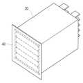
도2는 다수의 전지셀을 적층하여 바디(body)부분을 2차 포장재로 패키징한 단위모듈을 상단면에서 본 사시도이다.
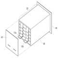
도3은 다수의 전지셀을 적층하여 바디(body)부분을 2차 포장재로 패키징한 단위모듈을 하단면에서 본 사시도이다.
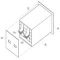
도4는 바디(body)부분을 2차 포장재로 패키징한 단위모듈의 하단면을 패키징하는 단계에 대한 사시도이다.
도5는 바디(body)부분 및 하단면을 패키징한 단위모듈을 하단면에서 본 사시도이다.
도 6a 내지 도 6c는 다수의 전지셀 탭의 연결 형태에 따라 단위모듈의 상단면을 패키징하는 단계에 대한 사시도이다.
도 7a 내지 도7c는 다수의 전지셀 탭의 연결 형태에 따라 패키징이 완성된 단위모듈의 사시도이다.
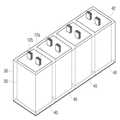
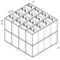
도 8a 내지 8c는 다수의 전지셀 탭의 연결 형태에 따라 패키징된 단위모듈을 모듈 케이스에 배치한 상태를 개략적으로 나타낸 사시도이다.
도9a 내지 도 9d는 본 발명에 따라 모듈 케이스내에 다양한 형태로 단위모듈들이 적층 또는 배열된 상태를 개략적으로 나타낸 사시도이다.1 is a perspective view schematically showing a battery cell for packaging an electrode assembly and an electrolyte solution as a primary packaging material.
FIG. 2 is a perspective view of a unit module in which a plurality of battery cells are stacked and a body portion is packaged in a secondary packaging material, as viewed from the upper surface.
FIG. 3 is a perspective view of a unit module in which a plurality of battery cells are stacked and a body portion is packaged in a secondary packaging material, as viewed from the lower end.
4 is a perspective view illustrating a step of packaging a lower end of a unit module in which a body part is packaged with a secondary packaging material.
FIG. 5 is a perspective view of a unit module having a body part and a bottom surface packaged as viewed from the lower end.
6A to 6C are perspective views illustrating a step of packaging the upper surface of the unit module according to connection forms of a plurality of battery cell taps.
FIGS. 7A to 7C are perspective views of a unit module in which packaging is completed according to a connection form of a plurality of battery cell taps. FIG.
8A to 8C are perspective views schematically showing a state in which a packaged unit module is arranged in a module case according to a connection form of a plurality of battery cell taps.
9A to 9D are perspective views schematically showing a state in which unit modules are stacked or arranged in various forms in a module case according to the present invention.
상기와 같은 목적을 달성하기 위하여 본 발명에 의한 중대형 전지팩의 패키징방법은,According to an aspect of the present invention, there is provided a method of packaging a middle- or large-
전극 조립체 및 전해액을 포함하는 전지셀을 1차 패키징하는 1 단계;A first step of firstly packaging a battery cell including an electrode assembly and an electrolyte;
상기 1차 패키징 된 다수의 전지셀을 적층, 또는 병렬 연결 또는 직렬연결 중 어느 하나의 방법으로 연결하여 단위모듈을 만들고 상단 및 하단을 제외한 바디(body) 부분만을 2차 패키징하는 2 단계;A second step of assembling the unit packed cells by connecting the plurality of primary packaged battery cells by any one of lamination, parallel connection, or serial connection, and secondary packaging only the upper and lower body parts except for the upper and lower ends;
상기 2차 패키징 된 단위모듈의 상단 및 하단을 패키징하는 3 단계; 및 상기 상단 및 하단이 패키징된 단위모듈들을 모듈 케이스에 고정하여 팩 조립하는 4 단계로 이루어진 것을 특징으로 한다.A third step of packaging upper and lower ends of the second packaged unit module; And fixing the packaged unit modules with the upper and lower ends to the module case and assembling the packs.
본 발명의 목적은 또한,An object of the present invention is also to provide
전극조립체 및 전해액을 포함하여 1차 포장재로 패키징 된 전지셀;A battery cell packaged with a primary packaging material including an electrode assembly and an electrolyte;
상기 전지셀을 적층하고 바디(body) 부분을 2차 포장재로 패키징한 후 상단면 및 하단면을 패키징한 단위 모듈; 및A unit module in which the battery cells are stacked, a body portion is packaged in a secondary packaging material, and the top and bottom surfaces are packaged; And
상기 단위모듈이 복수개 연결되어 포함되어 있는 모듈 케이스; 를 포함하고 있는 중대형 전지팩을 제공하는 것으로 이루어 질 수 있다.
A module case including a plurality of unit modules connected thereto; And a middle or large-sized battery pack.
이하, 도면을 참조하여 본 발명의 전지팩의 패키징방법에 대해 설명하는 것으로 본 발명의 구조에 대해 설명한다.Hereinafter, a method of packaging a battery pack of the present invention will be described with reference to the drawings, and a structure of the present invention will be described.
도 1은 전극조립체(11) 및 전해액을 1차 포장재(20)로 패키징한 전지셀(13)에 대해 개략적으로 나타낸 사시도이다.Fig. 1 is a perspective view schematically showing a
본 발명은 먼저, 제1단계로, 전극조립체(11) 및 전해액을 포함하는 전지셀(13)을 파우치형 포장재(20) 등을 이용하여 1차 패키징한다.In the first step, the
상기 1차 패키징을 위한 파우치형 포장재(20)는 전해액에 용해되지 않는 재질의 열가소성 수지이면 만족되며, 예를 들어 PE(폴리에틸렌), PP(폴리 프로필렌), PS(폴리스틸렌), PVC(염화비닐), nylon(폴리아미드), PET (폴리에틸렌테레프탈레이트) 등으로 이루어진 파우치형 포장재를 이용한다.The pouch-
또한, 상기 파우치형 포장재(20)는 상기 열가소성 수지 이외에 알루미늄 라미네이트와 같은 금속 라미네이트층이 더 내장된 파우치형 포장재일 수도 있다.In addition, the pouch-
상기 1차 패키징을 위한 파우치형 포장재는 아래 설명되는 2차 포장재의 재질에 따라, 상기 금속라미네이트층이 더 내장된 파우치형 포장재일 수 있고, 또는 상기 나열된 열가소성 수지만으로 이루어진 파우치형 포장재일 수도 있다. 즉, 제2단계의 패키징을 위한 2차 포장재가 수분 및 전해액의 침투가 가능한 재질이라면 상기 1차 포장재, 즉 파우치형 포장재는 금속이 더 내장된 파우치형 포장재를 사용하여 패키징하는 것이 바람직하다.The pouch-type packaging material for the primary packaging may be a pouch-type packaging material in which the metal laminate layer is further embedded, or a pouch-type packaging material made of the thermoplastic resin alone, depending on the material of the secondary packaging material described below. That is, if the secondary packaging material for the second-stage packaging is a material capable of permeating moisture and electrolytic solution, the primary packaging material, that is, the pouch-type packaging material, is preferably packaged using the pouch-
금속 라미네이트층이 더 내장된 파우치형 포장재의 경우, 금속 라미네이트의 외부는 상기 열가소성 수지로 도포되어 있어 절연특성이 우수하고, 금속이 내장되어 있어 강도가 보다 우수하며, 수분 또는 전해액 등이 단위셀로 침투되지 않는다.In the case of the pouch-type packaging material in which the metal laminate layer is further embedded, the outside of the metal laminate is coated with the thermoplastic resin, It does not penetrate.
본 발명에 있어, 1차 포장재(20)에 내장되는 전극조립체(11)는 스택형(적층형) 구조, 젤리-롤(권취형) 구조 등 다양한 구조가 가능하다.In the present invention, the
일반적으로 이차전지는 전극조립체의 구조, 전해질의 구성 등에 따라, 리튬이온 전지, 리튬이온 폴리머 전지, 리튬 폴리머 전지 등으로 분류되기도 하는 바, 그 중 제조비가 낮고 전해액의 누액 가능성이 적으며 전지 조립공정이 간편한 리튬이온 폴리머 전지가 본 발명에 바람직하게 사용될 수 있다.Generally, the secondary battery is classified into a lithium ion battery, a lithium ion polymer battery, and a lithium polymer battery depending on the structure of the electrode assembly, the configuration of the electrolyte, etc. Among them, the manufacturing cost is low and the leakage of the electrolyte is low, This simple lithium ion polymer battery can be preferably used in the present invention.
전극리드(12)의 한쪽 단부는 전극조립체의 전극 탭들이 부착된 상태로 파우치형 포장재의 내부에 위치하고 반대쪽 단부는 파우치형 포장재의 외부로 노출되어 있다. 상기 전극리드 중 양극리드는 특별히 한정하지 아니하며, 일반적으로 사용될 수 있는 알루미늄으로 만들어진 금속박편을 사용할 수 있고, 음극리드 또한, 일반적으로 사용되는 구리로 만들어진 금속 박편등을 이용할 수 있다. 상기 전극 탭들은 통상적으로 사용되는 스폿 용접 등의 방법에 의해 전극리드에 결합될 수 있으며, 상기 전극리드의 두께는 대략 200 내지 500 ㎛로 함이 바람직하다.One end of the
본 발명의 리튬이차전지는, 상기 파우치형 포장재(20)에 전해질이 함침되어 있는 양극/분리막/음극의 상기 전극조립체(11)를 안착시키고, 파우치형 포장재의 접합 부위에 고온 고압을 가하여 융착시켜 밀봉한다.The lithium secondary battery of the present invention is characterized in that the
상기와 같이 전지셀의 1차 패키징은 열가소성 수지 등을 이용하여 패키징함으로써, 이 후 전지의 사용 및 안전사고에 따라 셀 내부에 가스가 발생하는 경우, 쉽게 벤트(vent)될 수 있는 고분자 파우치형 포장재의 장점을 그대로 유지하여 사용중 가스의 발생으로 인한 위험을 미연에 방지할 수 있도록 하며, 전지셀을 먼저 유연성이 있는 파우치형 포장재로 1차 패키징하므로서, 전해액 등의 유출 및 전지셀과 금속 포장재의 접촉에 의한 절연현상 등을 방지할 수 있도록 한다.As described above, the primary packaging of the battery cells is packaged by using a thermoplastic resin or the like, and when the gas is generated in the cell due to the use of the battery and a safety accident, the polymer pouch- So that the risk of the generation of gas during use can be prevented, and the battery cell is firstly packaged with the flexible pouch-type packaging material first so that the leakage of the electrolyte solution and the contact between the battery cell and the metal packaging material And to prevent the insulation phenomenon caused by the insulation.
또한, 2차 포장재의 재질에 따라, 금속 라미네이트층이 내장된 고분자 파우치형 포장재 또는 고분자만으로 이루어진 파우치형 포장재들 중 하나를 선택하여 포장함으로써 전지의 안전성을 개선하면서도 컴팩트하고 단단하며 가벼운 리튬이차전지를 제공할 수 있다.In addition, depending on the material of the secondary packaging material, one of the polymer pouch-type packaging material or the polymer-only pouch-type packaging material containing the metal laminate layer may be selected and packaged to improve the safety of the battery and to provide a compact, hard and light lithium secondary battery .
상기 파우치형 포장재(20)의 두께는 특별히 제한하지 아니하나, 내구성 및 공간활용 또는 전지의 무게등을 고려하여 150~200㎛가 되도록 함이 바람직하다.The thickness of the pouch-
한편, 본 발명의 패키징 방법에 따르면, 상기 파우치형 포장재에 의해 1차 패키징 된 전지셀은 다수가 차례로 적층되고, 이렇게 1차 포장된 전지셀들이 다수 적층된 단위모듈의 바디(body)부분만을 먼저 2차 패키징한다.In the meantime, according to the packaging method of the present invention, a plurality of primary cells packed by the pouch-type packaging material are stacked in order, and only the body part of a plurality of stacked unit cells, Secondary packaging.
도2 및 도3은 상기 단위모듈의 바디부분(22)만을 2차 패키징한 상태에 대한 사시도이다.2 and 3 are perspective views illustrating a state in which only the
상기 다수의 전지셀들이 적층된 단위모듈에 있어서, 전극리드(12)가 돌출된 면을 상단면(24)이라고 하고 그 반대쪽 면을 하단면(26)이라고 하며, 상기 상단면(24) 및 하단면(26)을 제외한 다른 면들로 이루어진 부분을 바디부분(22)이라고 한다.In the unit module in which the plurality of battery cells are laminated, a surface on which the electrode leads 12 protrude is referred to as a
본 발명의 리튬이차전지 패키징 방법의 2단계에서는 상기 단위모듈의 바디부분(22)만을 먼저 패키징한다. 이를 위해 상기 상단면(24) 및 하단면(26)에 해당하는 양쪽 끝면이 개방된 플라스틱관 또는 금속관(30) 등의 2차 포장재를 이용하여 상기 전지셀들이 적층된 단위 모듈을 그대로 삽입한다.In the second step of the lithium secondary battery packaging method of the present invention, only the
이와 같이 1차 패키징 된 상기 다수의 전지셀들로 이루어진 단위모듈의 바디(body)부분만을 금속관(30) 또는 플라스틱관으로 2차 패키징함으로써 1차 패키징된 파우치형 포장재의 외부를 금속관(30) 또는 플라스틱관으로 단단히 고정할 수 있다.Only the body portion of the unit module composed of the plurality of primary cells packaged in this manner is secondarily packaged with the
이와 같이 보다 강도가 높은 포장재를 이용하여2차 패키징하여 단위모듈의 외부를 단단히 고정시킴으로서 파우치형 포장재(20)의 과도한 스웰링(swelling) 현상을 억제하고 전지의 외부를 단단하게 패키징하여 중대형 전지의 외부 충격 등으로부터 전지를 보호할 수 있으며 내부에 단위 셀 또는 단위모듈이 구조적으로 안전하게 고정될 수 있도록 한다.By securing the outer surface of the unit module firmly by secondary packaging using the packaging material having a higher strength as described above, excessive swelling of the pouch-
또한 상단면(24) 및 하단면(26)에 상응하는 부분은 개방된 형상의 금속관(30) 또는 플라스틱관을 이용하여 바디부분만을 2차 패키징하는바 상기 단위모듈을 그대로 삽입하면 되기 때문에 공정이 보다 용이하고 간편하게 이루어질 수 있게 된다.In addition, since only the body part is secondarily packaged using the
상기 2차 패키징을 위한 금속관(30)은 알루미늄, 주석, 크롬, 철, 니켈, 구리 및 이들의 합금 등으로 이루어진 군에서 선택된 어느 하나로 이루어진 것일 수 있으며, 플라스틱관은 PE(폴리에틸렌), PP(폴리 프로필렌), PS(폴리스틸렌), PVC(염화비닐), 아크릴 수지 등으로 이루어진 군에서 선택된 어느 하나로 이루어진 것일 수 있다. 다만, 바람직하게는 상기 2차 패키징재로서 알루미늄으로 이루어진 금속관을 사용하도록 한다. 이는 상기 파우치형 포장재의 스웰링 현상을 가장 효과적으로 방지할 수 있는 강도를 지니면서도 무게가 가볍기 때문이다. 도 2 및 도3은 본 발명의 일실시예로서, 2차 포장재를 금속관(30)으로 사용하는 경우를 나타내었다.The
상기와 같이 2차 포장재로서 알루미늄 등의 금속관(30)을 이용하는 경우, 1차 포장재는 금속 라미네이트를 내장하지 않는 파우치형 포장재를 사용하는 것이 바람직하다. 이 경우, 1차 패키징후 파우치형 포장재의 실링부 가장자리를 절단함으로써 발생할 수 있는 금속 라미네이트층의 돌출 및 이로 인한 전지의 절연현상 등을 방지할 수 있으면서도 외장재의 강도가 높고, 스웰링 현상을 효과적으로 억제할 수 있는 리튬이차전지를 제공할 수 있다.When the
상기 금속관(30) 또는 플라스틱관의 두께는 특별히 한정하지 아니하나 전지 내부공간의 활용 및 전지 전체의 무게를 고려하여 250㎛ 내지 2 mm 의 범위내로 한다.The thickness of the
소형 각형 전지의 경우 일반적으로 200 내지250㎛ 정도의 두께 로 이루어진 캔타입 포장재를 사용하나 이는 전지의 스웰링 현상을 억제하기에 어려움이 있으며, 또한 전지 내부의 열전달을 고려하여 최대 두께는 2mm 미만이 됨이 바람직하다.In the case of a small prismatic battery, a can type packing material having a thickness of about 200 to 250 μm is generally used, but it is difficult to suppress the swelling phenomenon of the battery. Also, considering the heat transfer inside the battery, .
도 2 및 도 3에서는 금속관(30)의 모양을 사각형으로 예시하였으나, 본 발명은 이에 한정되지 아니하며, 상기 금속관 또는 플라스틱관의 모양은, 각형 또는 원형 등의 다양한 형태로 이루어질 수 있다.2 and 3, the shape of the
한편, 상기 단위모듈의 바디부분(22)을 2차 패키징한 후에는, 개방되어 있는 단위모듈의 상단면(24) 및 하단면(26)을 패키징한다.On the other hand, after the
도4 내지 도 7c는 상기 단위모듈의 상단면(24)과 하단면(26)을 패키징하는 방법에 대해 도시하고 있으며, 이 중 도 6a 내지 도6c, 도7a 내지 도7c는 단위모듈의 상단면에 돌출된 다수의 전극탭들의 연결 형태를 각각 달리한 경우의 실시예에 대한 것이다.FIGS. 4 to 7C illustrate a method of packaging the
본 발명의 단위모듈의 하단면(26)은 바디부분을 패키징한 2차 포장재와 같은 재질의 금속판 또는 플라스틱판을 사용하여 패키징 하는 것도 가능하나, 바람직하게는 보호회로 또는 PTC 회로 등을 이용하여 패키징하도록 한다.The
상기 도면들을 참조하여 보면, 먼저 도4에 나타난 바와 같이, 상기 단위모듈의 하단면(26)을, 리튬이차전지의 패키징시 포함되는 보호 회로(40) 또는 PTC 회로를 이용하여 덮은 후에 접착제 등을 이용하여 금속관 또는 플라스틱관과 결합되도록 실링할 수 있다.4, the
이 때 사용되는 보호회로(40) 또는 PTC 회로의 면적은 상단면(24) 또는 하단면(26)의 면적과 같거나 0.2mm내지 2cm의 크기 만큼 크게 디자인한다. 이는, 상기 양끝 단면의 패키징이 모두 완료된 단위모듈들을 모듈 케이스에 직렬적으로 배열할 때, 보호회로(40) 또는 PTC 회로로 패키징된 하단면(26)을 모듈 케이스의 바닥에 고정시켜 수직으로 배열함으로써, 단위 모듈들이 모듈케이스 내에 보다 안전하고 단단하게 고정될 수 있도록 하기 위함이다. 따라서 하단면(26)에 부착되는 보호회로(40) 또는 PTC 회로의 면적이 넓을수록 조립된 셀들은 보다 안정적으로 고정될 수 있어 안전하다.The area of the
도 5는 단위모듈의 하단면(26)을 이보다 넓은 면적의 보호회로(40)로 실링한 상태에 대한 사시도이다.5 is a perspective view illustrating a state in which the
이로 인해, 충격이나 흔들림이 많은 중대형 디바이스 전원용 리튬 이차 전지에 있어, 구조적으로 보다 안전한 중대형 리튬이차전지를 제공할 수 있게 된다.As a result, it is possible to provide a more secure middle-sized lithium secondary battery in terms of structure in a lithium secondary battery for power supply of a medium and large-sized device with many shocks or fluctuations.
상기 보호회로(40) 또는 PTC 회로와 금속관(30) 또는 플라스틱관을 실링하는 접착제는 특별히 한정하지 아니하며, 아크릴 수지, 폴리에틸렌, 폴리에스테르 수지등을 이용하여 실링이 가능하며, 또는 피치 등을 이용하여 용융시켜 실링하는 것도 가능하다.The adhesive for sealing the
또한, 이와 같이 단위모듈의 2차 패키징재의 하부 실링부, 즉, 보호회로 또는 PTC 회로와 금속관 또는 플라스틱관이 접착된 부분은 2차 패키징된 포장재의 다른 부분들보다 쉽게 벤팅(venting)될 수 있는 부분으로서 내부 가스가 밖으로 배출될 수 있는 통로가 될 수 있다. 즉, 단위모듈의 바디 부분과 상단면 및 하단면의 2차 포장재들은 스웰링이 잘 되지 않는 높은 강도의 재질로 이루어진 포장재들로서 가스가 벤팅되기 어려운바, 전지셀들의 내부에서 발생된 가스는 상기와 같이 보호회로 등과 금속관 등이 접착된 하부 실링부 쪽으로 빠져나올 수 있도록 유도되며, 또한 내부 가스가 많이 발생되는 바디부분은 강도가 높은 금속관 또는 플라스틱관이 단단히 잡아줌으로써 내부에 발생된 가스가 좀 더 많이 밖으로 배출될 수 있도록 압력을 인가하는 효과 및 하부 실링부 쪽으로 가스가 벤트되도록 유도하는 효과를 제공한다. 이와 같은 효과로 인하여 전지셀 내부의 가스 발생으로 인한 단위모듈의 폭발 등의 위험성을 낮출 수 있어 안전성이 향상된 전지팩을 제공할 수 있게 된다. 따라서 바디부분의 2차 포장재와 하단면의 포장재와의 접착강도는 이와 같이 내부 가스의 배출효과 등을 고려하여 조절하도록 한다.In addition, the lower sealing portion of the secondary packaging material of the unit module, that is, the portion where the protection circuit or the PTC circuit is adhered to the metal pipe or the plastic pipe can be easily vented than other portions of the secondary packaging material It can be a passage through which the internal gas can be discharged to the outside. That is, the secondary packaging materials of the body portion, the upper surface, and the lower surface of the unit module are packaging materials made of a material having a high strength that does not easily swell and gas is difficult to be vented. In addition, the body part where the internal gas is generated is guided so that the metal tube or the plastic tube with high strength is firmly caught, so that the gas generated inside is more The effect of applying pressure to be discharged to the outside and the effect of inducing gas to be vented toward the lower sealing portion are provided. Such an effect can reduce the risk of explosion of the unit module due to the generation of gas in the battery cell, thereby providing a battery pack with improved safety. Therefore, the bonding strength between the secondary packaging material of the body part and the packaging material of the lower side is adjusted in consideration of the exhaust gas effect of the internal gas.
한편, 단위모듈의 상단면(24)은 도6a 및 도6b에 나타난 실시예들과 같이, 각 전지셀로부터 돌출된 각 전극탭들을 연결하여 하나의 양극리드(12a) 및 음극리드(12b)로 돌출되도록 할 수 있다.6A and 6B, the
또한, 이와 같이 각 탭들을 연결하여 하나의 전극리드로 만든 후 상단면을 패키징하는 경우, 그 패키징 과정을 단순화할 수 있다는 장점이 있을 수 있으나, 다수의 전지셀을 포함하는 단위모듈의 경우에는 하나의 양극리드 및 음극리드에 부하되는 전류의 양이 과다할 수 있는바, 바람직하게는 도6c에 나타난 실시예와 같이 다수의 전극리드들이 돌출되도록 단위모듈을 만들 수 있다.In addition, when the taps are connected to form one electrode lead and then the top surface is packaged, there is an advantage that the packaging process can be simplified. However, in the case of the unit module including a plurality of battery cells, The amount of electric current to be applied to the positive electrode lead and the negative electrode lead of the unit cell may be excessive, and preferably, the unit module may be formed such that a plurality of electrode leads protrude as in the embodiment shown in FIG. 6C.
다만, 도 6a 내지 도6c 등에 나타난 사시도는 본 발명에 따른 일실시예들을 예시한 것으로서 본 발명은 여기에 한정되지 아니하며, 단위모듈의 용량 및 패키징 공정의 단순화 등을 고려하여 다양한 형태 및 개수의 탭들이 형성되도록 만들 수 있음은 물론이다.6A to 6C illustrate one embodiment of the present invention, and the present invention is not limited thereto. In view of simplification of the capacity of the unit module and simplification of the packaging process, Of course, be formed.
이 후, 상기 단위모듈의 상단부는 전극리드들(12a, 12b)이 셀 밖으로 고정되도록 고안된 캡(42)으로 패키징된다. 상기 캡(42)은 상단면(24)의 면적과 동일하도록 하고 그 재질등에 있어서는 특별히 한정되지 아니하며 공지의 전지 패키징용 어셈블리 캡 등을 사용하는 것으로 만족된다. 상기 캡(42)은 형성된 전극리드의 형태 및 개수에 상응하는 개공부를 포함하는 어셈블리 캡인 것을 특징으로 하며, 상단부에 접착제를 이용하여 실링되거나 끼움방식으로 패키징 될 수 있다.The upper end of the unit module is then packaged into a
도 7a 내지 도7c는 본 발명의 리튬 이차전지 패키징 방법에 따른 제2단계 및 제3단계의 패키징 단계가 완료된 단위모듈의 형상을 개략적으로 나타낸 사시도이며, 돌출된 전극리드가 각각 다른 형태인 단위모듈들의 사시도이다.7A to 7C are perspective views schematically showing the shape of a unit module having completed the packaging step of the second and third steps according to the lithium secondary battery packaging method of the present invention, Respectively.
한편, 바디부분(22) 및 상단면(24)과 하단면(26)의 패키징이 완료된 단위모듈은 모듈 케이스에 직렬로 배열된다.On the other hand, the unit module in which the packaging of the
도8a 내지 8c는, 본 발명의 일 실시예에 따라, 1차 및 2차 패키징 완료된 단위모듈들을 모듈 케이스(50)에 직렬로 배열시킨 형상에 대한 개략적인 사시도이다. 상기 도8a 내지 8c에 나타난 모듈 케이스에 단위모듈의 배열 형태는 하나의 실시예를 나타낸 것이며, 본 발명에 따른 단위모듈은 보다 다양한 형태로 모듈 케이스에 적층 또는 배열될 수 있고, 또한 상기 실시예에서는 모듈 케이스(50)내에 4개의 단위모듈을 배열하고 있으나, 본 발명은 이에 한정되지 않고 모듈 케이스에 수용되는 단위모듈은 2개, 3개 또는 5개 이상의 복수개를 수용하는 구성들 또한 가능하다.8A to 8C are schematic perspective views of a configuration in which first and second packaged unit modules are arranged in series in a
도8a 내지 8c에 나타난 바와 같이, 단위모듈은 하단면(26)에 부착된 보호회로(40) 또는 PTC 회로가 아래쪽으로 위치하도록 하여 모듈 케이스(50)의 바닥면에 부착하고, 다수의 단위모듈들을 직렬 배열하여 모듈 케이스(50) 바닥에 상기 보호회로 등을 단단히 고정시킨다.8A to 8C, the unit module is attached to the bottom surface of the
이와 같이 단위모듈의 하단면(26)을 보호회로(40) 또는 PTC 회로 등을 이용하여 패키징함으로써, 보호회로(40) 또는 PTC가 전지의 팩 조립시 별도의 공간에 따로 위치하는 경우에 비해 전지 내부의 공간 활용도를 극대화 할 수 있으며, 또한, 별도의 고장장치를 사용하지 않고도 모듈 케이스(50)에 단위모듈들이 단단하게 고정될 수 있도록 하며 이로 인해 가볍고 컴팩트하면서도 안전성이 뛰어난 중대형 리튬이차전지를 제공할 수 있다.By packaging the
또한, 도 9a 내지 도9d에 나타난 바와 같이, 본 발명에 따른 단위모듈은 모듈 케이스내에 다양한 방향 및 적층 형태로 배열될 수 있다. 즉, 도 8a 내지 도8c 및 도 9a와 같이 단위모듈이 모듈 케이스 내에서 한 방향으로 배열될 수도 있고, 도 9b와 같이 양쪽 방향으로 병렬 배열됨으로써 하나의 면을 형성할 수도 있으며, 도 9c와 같이 단위모듈의 직렬방향으로도 배열하여 다수의 단위모듈을 연결할 수도 있다. 또한 도 9d와 같이, 다수의 단위모듈을 포함하고 있는 모듈 케이스들을 병렬 또는 직렬 연결하는 방법으로 고용량의 전지팩을 제공 할 수도 있다. 이러한 단위모듈의 적층 또는 배열 형태에 따라 모듈 케이스의 형태가 변형될 수 있음은 물론이다.
Also, as shown in FIGS. 9A to 9D, the unit module according to the present invention may be arranged in various directions and laminated shapes in the module case. That is, the unit modules may be arranged in one direction in the module case as shown in FIGS. 8A to 8C and FIG. 9A, or may be arranged in parallel in both directions as shown in FIG. 9B, A plurality of unit modules may be connected by arranging the unit modules in a serial direction. Also, as shown in FIG. 9D, a high-capacity battery pack may be provided by connecting the module cases including a plurality of unit modules in parallel or in series. It goes without saying that the shape of the module case may be modified depending on the stacking or arrangement of the unit modules.
한편, 2차 패키징에 의한 단위 모듈의 전극리드가 모두 상단면에 위치하지 않고 각기 다른 방향에 위치하는 경우에는, 전극리드가 위치하는 양 끝단면 중 어느 한 면을 보호회로 또는 PTC 회로를 이용하여 막은 후 이를 금속관 또는 플라스틱관과 접착제를 이용하여 실링 한다. 이때 접착시 이용되는 접착제는 상기의 접착제 및 접착 방법과 동일하다.On the other hand, in the case where the electrode leads of the unit module by the secondary packaging are not all located on the upper surface but located in different directions, one of the both end surfaces on which the electrode lead is located is protected by a protection circuit or a PTC circuit The membrane is then sealed with a metal or plastic tube and adhesive. At this time, the adhesive used in the bonding is the same as the adhesive and the bonding method described above.
상기와 같은 경우도, 상단면 또는 하단면의 패키징을 위해 사용되는 보호회로 또는 PTC 회로의 면적은 금속관 또는 플라스틱 관의 상단 또는 하단의 면적과 같거나 0.2mm내지 2cm만큼 크게 디자인하여, 단위셀 또는 단위 모듈을 패키징하도록 한다.In such a case, the area of the protection circuit or the PTC circuit used for the packaging of the upper end surface or the lower end surface is designed to be 0.2 mm to 2 cm larger than the area of the upper or lower end of the metal pipe or the plastic pipe, The unit module is packaged.
보호회로 또는 PTC 회로로 실링한 면의 반대쪽 면은 전극리드가 돌출될 수 있도록 형성된 캡을 이용하여 패키징한다.The opposite side of the surface sealed with the protection circuit or the PTC circuit is packaged using a cap formed so that the electrode lead protrudes.
상기와 같이 양쪽 끝단의 패키징이 완료된 단위모듈 역시 모듈 케이스에 직렬로 배열한다. 이 때 패키징된 단위셀 또는 단위모듈은 전극리드가 위치한 양쪽 면을 제외한 면들 중에서 면적이 좁은 쪽의 어느 한 면을 모듈 케이스의 바닥과 접하도록 배열한다. 이 때 상기 모듈 케이스에 배열된 단위모듈의 좌우 양쪽 면 중 어느 한 면에 부착되어 있는 보호회로 또는 PTC회로는, 모듈 케이스의 옆면과 닿도록 하여 단단하게 부착시킴으로서 전지의 구조적 안정을 도모할 수 있다.
As described above, the unit modules that have been packaged at both ends are also arranged in series in the module case. At this time, the packaged unit cells or the unit modules are arranged such that one side of the packaged unit cell or the unit module, which is narrower than the two faces on which the electrode leads are located, is in contact with the bottom of the module case. At this time, the protection circuit or the PTC circuit attached to either one of the left and right sides of the unit module arranged in the module case can be stably attached so as to come in contact with the side surface of the module case, .
본 발명의 패키징 방법에 따라 제조된 중대형 전지는, 소망하는 출력 및 용량에 따라 다수의 전지셀 또는 단위모듈들을 조합하여 제조될 수 있으며, 앞서 설명한 바와 같은 장착 효율성, 구조적 안정성 등을 고려할 때, 한정된 장착 공간을 갖고 잦은 진동과 강한 충격 등에 노출되는 전기 자동차, 하이브리드 전기 자동차 또는 전기 오토바이, 전기 자전거 등의 전원으로 바람직하게 사용될 수 있지만 적용 범위가 이들만으로 한정되는 것은 아니다.
The middle- or large-sized battery manufactured according to the packaging method of the present invention can be manufactured by combining a plurality of battery cells or unit modules according to a desired output and capacity. In consideration of the mounting efficiency and structural stability as described above, A hybrid electric vehicle, an electric motorcycle, an electric bicycle, etc., which have a mounting space and are exposed to frequent vibration and strong shock, but the scope of application is not limited thereto.
11 : 전극조립체 12 : 전극리드 13 : 전지셀
20 : 파우치형 포장재 22 : 바디(body)부분 24 : 상단면
26 : 하단면 30 : 금속관 40 : 보호회로
12a: 양극리드 12b: 음극리드 42 : 캡
50 : 모듈 케이스11: electrode assembly 12: electrode lead 13: battery cell
20: pouch type packing material 22: body part 24: upper surface
26: bottom surface 30: metal tube 40: protection circuit
12a:
50: Module case
Claims (26)
Translated fromKorean전극조립체 및 전해액을 포함하는 전지셀을 1차 패키징하는 제1 단계;
상기 1차 패키징 된 다수의 전지셀을 적층한 단위모듈의 바디(body) 부분을 2차 패키징하는 제2 단계;
상기 단위모듈의 상단면 및 하단면을 패키징하는 3 단계; 및
상기 3단계에 의한 단위모듈을 모듈 케이스에 배열하는 4 단계로 이루어진 것을 특징으로 하고,
상기 제2단계의 2차 패키징은, 상단면 및 하단면에 상응하는 양 끝단면이 개방된 플라스틱관 또는 금속관으로 패키징하는 것이고,
상기 3 단계에 의한 단위모듈의 상단면 또는 하단면을 패키징하기 위한 포장재는, 보호회로 또는 PTC회로인 것이며,
상기 3 단계에 있어서, 하단면의 패키징시 하부 실링부 형성 단계를 더 포함하는 것을 특징으로 하는 리튬 이차전지 팩의 패키징방법.
In a method of packaging a lithium secondary battery pack,
A first step of firstly packaging a battery cell including an electrode assembly and an electrolyte;
A second step of secondary packaging the body part of the unit module in which the plurality of primary cells are laminated;
Packaging the top and bottom surfaces of the unit module; And
And arranging the unit modules according to the three steps in the module case.
The secondary packaging in the second step is to be packaged with a plastic tube or metal tube having open end surfaces corresponding to the top and bottom surfaces,
The packaging material for packaging the upper surface or the lower surface of the unit module according to the above three steps is a protection circuit or a PTC circuit,
[6] The method of claim 1, further comprising forming a lower sealing part when packaging the lower surface in step 3.
상기 1 단계의 1차 패키징을 위한 포장재는 전해액에 용해되지 않는 열가소성 수지만으로 이루어진 파우치형 포장재를 이용하여 패키징하는 것을 특징으로 하는 리튬 이차전지 팩의 패키징방법.
The method according to claim 1,
Wherein the packaging material for the first-stage packaging in the first step is packaged using a pouch-type packaging material made only of a thermoplastic resin that is not dissolved in the electrolyte solution.
상기 전해액에 용해되지 않는 열가소성 수지는 PE(폴리에틸렌), PP(폴리 프로필렌), PS(폴리스틸렌), PVC(염화비닐), nylon(폴리아미드), PET (폴리에틸렌테레프탈레이트)로 이루어진 군에서 선택된 어느 하나인 것을 특징으로 하는 리튬 이차전지 팩의 패키징방법.
3. The method of claim 2,
The thermoplastic resin which is not soluble in the electrolytic solution may be any one selected from the group consisting of PE (polyethylene), PP (polypropylene), PS (polystyrene), PVC (vinyl chloride), nylon (polyamide), and PET (polyethylene terephthalate) Wherein the secondary battery pack is a battery pack.
상기 1 단계의 1차 패키징을 위한 포장재는 금속 라미네이트층이 내장되어 있고 상기 금속라미네이트층의 외부는 전해액에 용해되지 않는 열가소성 수지로 이루어진 파우치형 포장재인 것을 특징으로 하는 리튬 이차전지 팩의 패키징방법.
The method according to claim 1,
Wherein the packaging material for the first-stage packaging of the first stage is a pouch-type packaging material comprising a metal laminate layer and a thermoplastic resin which is not dissolved in the electrolyte solution outside the metal laminate layer.
상기 금속 라미네이트층은 알루미늄 금속라미네이트층인 것을 특징으로 하는 리튬 이차전지 팩의 패키징방법.
5. The method of claim 4,
Wherein the metal laminate layer is an aluminum metal laminate layer.
상기 플라스틱 관은 PE(폴리에틸렌), PP(폴리 프로필렌), PS(폴리스틸렌), PVC(염화비닐), 아크릴 수지로 이루어진 군에서 선택되는 어느 하나로 이루어진 것을 특징으로 하는 리튬 이차전지 팩의 패키징방법.
The method according to claim 1,
Wherein the plastic tube is made of any one selected from the group consisting of PE (polyethylene), PP (polypropylene), PS (polystyrene), PVC (vinyl chloride), and acrylic resin.
상기 금속관은 알루미늄, 철, 니켈, 구리 또는 이들의 합금으로 이루어진 군에서 선택되는 어느 하나로 이루어진 것을 특징으로 하는 리튬 이차전지의 팩의 패키징방법.
The method according to claim 1,
Wherein the metal tube is made of any one selected from the group consisting of aluminum, iron, nickel, copper, and alloys thereof.
상기 보호회로 또는 PTC회로의 면적은, 상기 플라스틱관 또는 금속관의 단면의 크기와 같거나 또는 0.2mm내지 2cm만큼 더 큰 것을 특징으로 하는 리튬 이차전지 팩의 패키징방법.
The method according to claim 1,
Wherein an area of the protection circuit or the PTC circuit is equal to or larger than a size of a cross section of the plastic tube or the metal tube by 0.2 mm to 2 cm.
상기4 단계는, 단위 모듈의 상단면 또는 하단면에 부착된 보호회로 또는 PTC 회로가 모듈 케이스의 바닥면에 닿도록 단위모듈을 수직 배열하는 것을 특징으로 하는 리튬 이차전지 팩의 패키징방법.
The method according to claim 1,
Wherein the unit module is arranged vertically such that the protection circuit or the PTC circuit attached to the upper surface or the lower surface of the unit module contacts the bottom surface of the module case.
상기 단위 모듈은 전극리드가 동일한 방향에 위치되어 있는 것을 특징으로 하는 리튬 이차전지 팩의 패키징방법.
12. The method of claim 11,
Wherein the unit modules are positioned in the same direction as the electrode leads.
상기 단위 모듈은 모듈 케이스내에 직렬 또는 병렬로 적층 또는 나열되는 것을 특징으로 하는 리튬 이차전지 팩의 패키징 방법.
12. The method of claim 11,
Wherein the unit modules are stacked or arranged in series or in parallel within the module case.
상기 전지셀을 적층하고 바디(body) 부분을 2차 포장재로 패키징한 후 전극탭이 위치한 면의 반대되는 하단면은 보호회로 또는 PTC 회로로 패키징하고 전극탭이 위치한 상단면은 캡 어셈블리로 패키징한 단위 모듈; 및
상기 단위모듈이 복수개 포함되어 있는 모듈 케이스를 포함하고,
상기 2차 포장재는 상단면 및 하단면에 상응하는 양 끝단면이 개방된 플라스틱관 또는 금속관이고, 상기 하단면은 하부 실링부를 더 포함하는 것을 특징으로 하는 중대형 전지팩.
A battery cell packaged with a primary packaging material including an electrode assembly and an electrolyte;
The battery cell is stacked and the body part is packaged with the secondary packaging material. The opposite lower end surface of the surface on which the electrode tab is located is packaged by a protection circuit or a PTC circuit, and the upper surface where the electrode tab is located is packaged by a cap assembly Unit module; And
And a module case including a plurality of unit modules,
Wherein the secondary packaging material is a plastic tube or a metal tube having openings at both end surfaces corresponding to the upper end surface and the lower end surface, and the lower end surface further includes a lower sealing portion.
상기 1 차 포장재는 전해액에 용해되지 않는 열가소성 수지만으로 이루어진 파우치형 포장재인 것을 특징으로 하는 중대형 전지팩.
15. The method of claim 14,
Wherein the primary packaging material is a pouch-type packaging material made only of a thermoplastic resin that is not dissolved in an electrolytic solution.
상기 전해액에 용해되지 않는 열가소성 수지는 PE(폴리에틸렌), PP(폴리 프로필렌), PS(폴리스틸렌), PVC(염화비닐), nylon(폴리아미드), PET (폴리에틸렌테레프탈레이트)로 이루어진 군에서 선택된 어느 하나인 것을 특징으로 하는 중대형 전지팩.
16. The method of claim 15,
The thermoplastic resin which is not soluble in the electrolytic solution may be any one selected from the group consisting of PE (polyethylene), PP (polypropylene), PS (polystyrene), PVC (vinyl chloride), nylon (polyamide), and PET (polyethylene terephthalate) Wherein the battery pack is a battery pack.
상기 1차 포장재는 금속 라미네이트층이 내장되어 있고, 상기 금속라미네이트층의 외부는 전해액에 용해되지 않는 열가소성 수지로 이루어진 파우치형 포장재인 것을 특징으로 하는 중대형 전지팩.
15. The method of claim 14,
Wherein the primary packaging material is a pouch-type packaging material having a metal laminate layer embedded therein, and the outside of the metal laminate layer is a thermoplastic resin that is not dissolved in an electrolyte solution.
상기 금속 라미네이트층은 알루미늄 금속라미네이트층인 것을 특징으로 하는 중대형 전지팩.
18. The method of claim 17,
Wherein the metal laminate layer is an aluminum metal laminate layer.
상기 플라스틱 관은 PE(폴리에틸렌), PP(폴리 프로필렌), PS(폴리스틸렌), PVC(염화비닐), 아크릴 수지로 이루어진 군에서 선택되는 어느 하나로 이루어진 것을 특징으로 하는 중대형 전지팩.
15. The method of claim 14,
Wherein the plastic tube is made of any one selected from the group consisting of PE (polyethylene), PP (polypropylene), PS (polystyrene), PVC (vinyl chloride), and acrylic resin.
상기 금속관은 알루미늄, 철, 니켈, 구리 또는 이들의 합금으로 이루어진 군에서 선택되는 어느 하나로 이루어진 것을 특징으로 하는 중대형 전지팩.
15. The method of claim 14,
Wherein the metal tube is made of any one selected from the group consisting of aluminum, iron, nickel, copper, and alloys thereof.
상기 보호회로 또는 PTC의 면적은, 상기 플라스틱관 또는 금속관의 단면의 크기와 같거나 또는 0.2mm내지 2cm만큼 더 큰 것을 특징으로 하는 중대형 전지팩.
15. The method of claim 14,
Wherein an area of the protection circuit or the PTC is equal to or larger than a size of a cross section of the plastic tube or the metal tube by 0.2 mm to 2 cm.
상기 전지팩은 단위모듈의 상단면 또는 하단면에 부착된 보호회로 또는 PTC 회로가 모듈 케이스의 바닥면과 닿도록 단위 모듈들을 수직으로 배열하여 연결한 것을 특징으로 하는 중대형 전지팩.
17. The method of claim 16,
Wherein the unit modules are vertically arranged so that the protection circuit or the PTC circuit attached to the upper surface or the lower surface of the unit module contacts the bottom surface of the module case.
상기 단위모듈은 전극리드가 동일한 방향에 위치되어 있는 것을 특징으로 하는 중대형 전지팩.
24. The method of claim 23,
Wherein the unit module has the electrode leads positioned in the same direction.
상기 단위 모듈은 모듈 케이스내에 직렬 또는 병렬로 적층 또는 나열되는 것을 특징으로 하는 중대형 전지팩.
24. The method of claim 23,
Wherein the unit modules are stacked or arranged in series or in parallel within the module case.
상기 전지팩은 파워 툴(power tool); 전기차(Electric Vehicle, EV), 하이브리드 전기차(Hybrid Electric Vehicle, HEV) 및 플러그인 하이브리드 전기차(Plug-in Hybrid Electric Vehicle, PHEV)를 포함하는 전기차; E-bike, E-scooter를 포함하는 전기 이륜차; 전기 골프 카트(Electric golf cart); 전기 트럭; 전기 상용차의 전원으로 사용되는 것을 특징으로 하는 중대형 전지팩.
15. The method of claim 14,
The battery pack may include a power tool; An electric vehicle including an electric vehicle (EV), a hybrid electric vehicle (HEV), and a plug-in hybrid electric vehicle (PHEV); Electric motorcycle including E-bike, E-scooter; Electric golf cart; Electric truck; Wherein the battery pack is used as a power source for an electric commercial vehicle.
Priority Applications (1)
| Application Number | Priority Date | Filing Date | Title |
|---|---|---|---|
| KR1020100027261AKR101456735B1 (en) | 2010-03-26 | 2010-03-26 | Middle or large sized battery pack and packaging method thereof |
Applications Claiming Priority (1)
| Application Number | Priority Date | Filing Date | Title |
|---|---|---|---|
| KR1020100027261AKR101456735B1 (en) | 2010-03-26 | 2010-03-26 | Middle or large sized battery pack and packaging method thereof |
Publications (2)
| Publication Number | Publication Date |
|---|---|
| KR20110108010A KR20110108010A (en) | 2011-10-05 |
| KR101456735B1true KR101456735B1 (en) | 2014-10-31 |
Family
ID=45025902
Family Applications (1)
| Application Number | Title | Priority Date | Filing Date |
|---|---|---|---|
| KR1020100027261AActiveKR101456735B1 (en) | 2010-03-26 | 2010-03-26 | Middle or large sized battery pack and packaging method thereof |
Country Status (1)
| Country | Link |
|---|---|
| KR (1) | KR101456735B1 (en) |
Families Citing this family (4)
| Publication number | Priority date | Publication date | Assignee | Title |
|---|---|---|---|---|
| KR101586641B1 (en) | 2014-10-15 | 2016-01-20 | 세방전지(주) | Battery pack module housing |
| CN112117480A (en)* | 2019-06-20 | 2020-12-22 | 南京德朔实业有限公司 | Battery pack and electric tool adopting same |
| AU2019451585B2 (en) | 2019-06-20 | 2024-02-08 | Nanjing Chervon Industry Co., Ltd. | Battery pack and combination of a power tool and the battery pack |
| CN112542663A (en)* | 2019-09-20 | 2021-03-23 | 南京德朔实业有限公司 | Battery pack and electric tool adopting same |
Citations (4)
| Publication number | Priority date | Publication date | Assignee | Title |
|---|---|---|---|---|
| KR20000033228A (en)* | 1998-11-20 | 2000-06-15 | 김순택 | Secondary battery |
| JP2001307784A (en)* | 2000-04-20 | 2001-11-02 | Japan Storage Battery Co Ltd | Battery set |
| JP2008243526A (en)* | 2007-03-27 | 2008-10-09 | Hitachi Vehicle Energy Ltd | Battery module |
| JP2008251342A (en)* | 2007-03-30 | 2008-10-16 | Dainippon Printing Co Ltd | Lithium ion battery and battery pack provided with the same |
- 2010
- 2010-03-26KRKR1020100027261Apatent/KR101456735B1/enactiveActive
Patent Citations (4)
| Publication number | Priority date | Publication date | Assignee | Title |
|---|---|---|---|---|
| KR20000033228A (en)* | 1998-11-20 | 2000-06-15 | 김순택 | Secondary battery |
| JP2001307784A (en)* | 2000-04-20 | 2001-11-02 | Japan Storage Battery Co Ltd | Battery set |
| JP2008243526A (en)* | 2007-03-27 | 2008-10-09 | Hitachi Vehicle Energy Ltd | Battery module |
| JP2008251342A (en)* | 2007-03-30 | 2008-10-16 | Dainippon Printing Co Ltd | Lithium ion battery and battery pack provided with the same |
Also Published As
| Publication number | Publication date |
|---|---|
| KR20110108010A (en) | 2011-10-05 |
Similar Documents
| Publication | Publication Date | Title |
|---|---|---|
| KR101383629B1 (en) | Battery Cell Havig Through Hole and Battery Pack Comprising The Same | |
| KR101595611B1 (en) | a secondary battery for improving energy degree | |
| KR101264527B1 (en) | Pouch case and battery pack using the same | |
| KR101508416B1 (en) | Pouch-type secondary battery | |
| KR101472178B1 (en) | Pouch typed battery having a non-exposure sealing portion | |
| KR102425151B1 (en) | Secondary Battery Pouch-Type Case Having Gas Discharge Port | |
| KR101305218B1 (en) | Battery Module Having Fixing Member and Coupling Member, and Battery Pack Employed with the Same | |
| JP2013058483A (en) | Secondary battery of novel structure and battery pack having the same | |
| JP2008204816A (en) | Assembled battery, vehicle equipped with this assembled battery, and battery-equipped device equipped with this assembled battery | |
| EP4064427B1 (en) | Pouch type secondary battery and battery module including the same | |
| KR101517044B1 (en) | Secondary Battery Having Case with Multi Electrode Assembly-Receiving Portion | |
| KR101501431B1 (en) | Battery Cell Including Pouch-type Cell and Transformed to Prismatic Shape | |
| KR20160019785A (en) | Pouch type secondary battery and method for manufacturing the same | |
| KR20120048937A (en) | Battery module and lithium secondary battery pack comprising the same | |
| KR101456735B1 (en) | Middle or large sized battery pack and packaging method thereof | |
| KR101472613B1 (en) | Middle or large sized battery pack and packaging method thereof | |
| KR101741123B1 (en) | Battery Cell Having Through Hole | |
| KR20140032710A (en) | Method for preparing pouch-type secondary battery | |
| KR20170009495A (en) | Pouch-type Secondary Battery Having Shock Absorption Layer in Battery Case | |
| KR101516449B1 (en) | Middle or large sized battery pack and packaging method thereof | |
| KR20160125644A (en) | Battery Module Having Fixing Frame and Method for Forming Fixing Frame on Battery Module | |
| KR101464796B1 (en) | Middle or large sized battery pack and packaging method thereof | |
| KR101913866B1 (en) | Secondary Battery Module | |
| EP4531183A1 (en) | Battery module and battery pack including same | |
| KR20250037998A (en) | Battery pack and device including the same |
Legal Events
| Date | Code | Title | Description |
|---|---|---|---|
| PA0109 | Patent application | St.27 status event code:A-0-1-A10-A12-nap-PA0109 | |
| PG1501 | Laying open of application | St.27 status event code:A-1-1-Q10-Q12-nap-PG1501 | |
| R17-X000 | Change to representative recorded | St.27 status event code:A-3-3-R10-R17-oth-X000 | |
| A201 | Request for examination | ||
| PA0201 | Request for examination | St.27 status event code:A-1-2-D10-D11-exm-PA0201 | |
| D13-X000 | Search requested | St.27 status event code:A-1-2-D10-D13-srh-X000 | |
| D14-X000 | Search report completed | St.27 status event code:A-1-2-D10-D14-srh-X000 | |
| E902 | Notification of reason for refusal | ||
| PE0902 | Notice of grounds for rejection | St.27 status event code:A-1-2-D10-D21-exm-PE0902 | |
| E13-X000 | Pre-grant limitation requested | St.27 status event code:A-2-3-E10-E13-lim-X000 | |
| P11-X000 | Amendment of application requested | St.27 status event code:A-2-2-P10-P11-nap-X000 | |
| P13-X000 | Application amended | St.27 status event code:A-2-2-P10-P13-nap-X000 | |
| E701 | Decision to grant or registration of patent right | ||
| PE0701 | Decision of registration | St.27 status event code:A-1-2-D10-D22-exm-PE0701 | |
| GRNT | Written decision to grant | ||
| PR0701 | Registration of establishment | St.27 status event code:A-2-4-F10-F11-exm-PR0701 | |
| PR1002 | Payment of registration fee | St.27 status event code:A-2-2-U10-U11-oth-PR1002 Fee payment year number:1 | |
| PG1601 | Publication of registration | St.27 status event code:A-4-4-Q10-Q13-nap-PG1601 | |
| PN2301 | Change of applicant | St.27 status event code:A-5-5-R10-R13-asn-PN2301 St.27 status event code:A-5-5-R10-R11-asn-PN2301 | |
| R18-X000 | Changes to party contact information recorded | St.27 status event code:A-5-5-R10-R18-oth-X000 | |
| FPAY | Annual fee payment | Payment date:20170919 Year of fee payment:4 | |
| PR1001 | Payment of annual fee | St.27 status event code:A-4-4-U10-U11-oth-PR1001 Fee payment year number:4 | |
| P22-X000 | Classification modified | St.27 status event code:A-4-4-P10-P22-nap-X000 | |
| FPAY | Annual fee payment | Payment date:20181016 Year of fee payment:5 | |
| PR1001 | Payment of annual fee | St.27 status event code:A-4-4-U10-U11-oth-PR1001 Fee payment year number:5 | |
| R18-X000 | Changes to party contact information recorded | St.27 status event code:A-5-5-R10-R18-oth-X000 | |
| R18-X000 | Changes to party contact information recorded | St.27 status event code:A-5-5-R10-R18-oth-X000 | |
| R18-X000 | Changes to party contact information recorded | St.27 status event code:A-5-5-R10-R18-oth-X000 | |
| FPAY | Annual fee payment | Payment date:20191016 Year of fee payment:6 | |
| PR1001 | Payment of annual fee | St.27 status event code:A-4-4-U10-U11-oth-PR1001 Fee payment year number:6 | |
| PR1001 | Payment of annual fee | St.27 status event code:A-4-4-U10-U11-oth-PR1001 Fee payment year number:7 | |
| P22-X000 | Classification modified | St.27 status event code:A-4-4-P10-P22-nap-X000 | |
| PN2301 | Change of applicant | St.27 status event code:A-5-5-R10-R11-asn-PN2301 | |
| PN2301 | Change of applicant | St.27 status event code:A-5-5-R10-R14-asn-PN2301 | |
| PR1001 | Payment of annual fee | St.27 status event code:A-4-4-U10-U11-oth-PR1001 Fee payment year number:8 | |
| P22-X000 | Classification modified | St.27 status event code:A-4-4-P10-P22-nap-X000 | |
| PR1001 | Payment of annual fee | St.27 status event code:A-4-4-U10-U11-oth-PR1001 Fee payment year number:9 | |
| PR1001 | Payment of annual fee | St.27 status event code:A-4-4-U10-U11-oth-PR1001 Fee payment year number:10 | |
| PR1001 | Payment of annual fee | St.27 status event code:A-4-4-U10-U11-oth-PR1001 Fee payment year number:11 | |
| PR1001 | Payment of annual fee | St.27 status event code:A-4-4-U10-U11-oth-PR1001 Fee payment year number:12 |