KR101455928B1 - Mass flow controller with motor driving circuit - Google Patents
Mass flow controller with motor driving circuitDownload PDFInfo
- Publication number
- KR101455928B1 KR101455928B1KR1020130037244AKR20130037244AKR101455928B1KR 101455928 B1KR101455928 B1KR 101455928B1KR 1020130037244 AKR1020130037244 AKR 1020130037244AKR 20130037244 AKR20130037244 AKR 20130037244AKR 101455928 B1KR101455928 B1KR 101455928B1
- Authority
- KR
- South Korea
- Prior art keywords
- flow rate
- plug
- motor
- shaft
- fluid
- Prior art date
- Legal status (The legal status is an assumption and is not a legal conclusion. Google has not performed a legal analysis and makes no representation as to the accuracy of the status listed.)
- Expired - Fee Related
Links
Images


Classifications
- G—PHYSICS
- G05—CONTROLLING; REGULATING
- G05D—SYSTEMS FOR CONTROLLING OR REGULATING NON-ELECTRIC VARIABLES
- G05D7/00—Control of flow
- G05D7/06—Control of flow characterised by the use of electric means
- G05D7/0617—Control of flow characterised by the use of electric means specially adapted for fluid materials
- G—PHYSICS
- G05—CONTROLLING; REGULATING
- G05D—SYSTEMS FOR CONTROLLING OR REGULATING NON-ELECTRIC VARIABLES
- G05D7/00—Control of flow
- G05D7/01—Control of flow without auxiliary power
- G05D7/0106—Control of flow without auxiliary power the sensing element being a flexible member, e.g. bellows, diaphragm, capsule
Landscapes
- Physics & Mathematics (AREA)
- General Physics & Mathematics (AREA)
- Engineering & Computer Science (AREA)
- Automation & Control Theory (AREA)
- Flow Control (AREA)
- Electrically Driven Valve-Operating Means (AREA)
Abstract
Translated fromKoreanDescription
Translated fromKorean본 발명은 기체 또는 액체 상태의 유체를 기 설정된 유량 값과의 편차 없이 공급하고, 또한 이종 간의 유체를 정해진 비율로 혼합하여 공급될 수 있도록 정밀 제어하는 장치에 관한 것이다.The present invention relates to an apparatus for precisely controlling a gas or a liquid state fluid to be supplied without any deviation from a predetermined flow rate value and to be supplied by mixing a different type of fluid at a predetermined ratio.
유체 정밀 질량 유량제어장치는 기체 또는 액체 상태의 유체를 솔레노이드 밸브의 온/오프 동작으로 유량을 제어하여 공급하는 장치이다.The fluid precision mass flow controller is a device for controlling the flow rate of the gas or liquid fluid by on / off operation of the solenoid valve.
도 1은 종래 솔레노이드 밸브로 제어하는 유체 정밀 질량 유량제어장치의 구조를 나타내는 대략적인 단면도이다. 도 1에 도시된 바와 같이 유체가 통과하는 공급 라인의 유입구(21)에 유체 흐름량을 측정하는 센서(10)가 위치하여 유량을 감지하며, 감지된 유체 흐름의 양을 전기적 신호로 변환하여 유량 측정 회로(11)로 보내어 진다. 그리고 유량 측정 회로(11)는 사용자에 의해 결정된 설정 값을 솔레노이드 밸브의 작동 회로(12)로 전달되며, 유체의 유량 제어는 솔레노이드 밸브(13)의 스위치(20) 온/오프 동작으로 제어된다.1 is a schematic cross-sectional view showing the structure of a fluid precision mass flow rate control apparatus which is controlled by a conventional solenoid valve. As shown in FIG. 1, a
도 2는 도 1에 제시된 종래 솔레노이드 밸브의 내부 구조를 도시한 단면도이다. 도 2에 도시된 바와 같이 솔레노이드 밸브는 도 1에서처럼 솔레노이드 밸브 작동 회로에서 전기적 신호를 받아 작동된 스위치는 온/오프 동작으로 솔레노이드 코일(13a)로 전류량을 인가하게 된다. 인가된 전류량은 솔레노이드 코일(13a)을 통해 밸브 내부에 위치하는 플런저(14)를 진동시키며, 이때 플런저는 상,하로 동작하게 된다. 그리고 유체의 유량 제어는 플런저(14)와 플런저 하부에 연결된 밸브시트(15)와의 사이에 위치한 스프링(16)의 탄성 한도 내에서 밸브시트(15)가 들어 올려지는 정도에 따라 오리피스 내경(19)으로 흐르는 유량을 조절하기 때문에 공급되는 유량의 범위가 저압에서는 많은 유량을 흘릴 수가 없다.FIG. 2 is a sectional view showing the internal structure of the conventional solenoid valve shown in FIG. 1. FIG. As shown in FIG. 2, the solenoid valve receives an electrical signal from the solenoid valve operating circuit as shown in FIG. 1, and the operated switch applies an amount of current to the
많은 유량의 유체를 공급하기 위해서는 유입되는 유체의 압력이 높아야 하며 오리피스(18)의 내경도 커져야 하는데, 오리피스의 내경(19)이 아무리 커져도 오리피스(18)와 밸브시트(15) 간의 간격(17)이 적어서 많은 유량을 흘릴 수 없고, 솔레노이드 밸브는 동작시 플런저(14)의 진동과 소음이 발생 되며, 플런저(14)를 제조 가공할 때 플런저 각 각의 가공 치수가 틀려 가공 편차에 의한 유량 편차가 발생 되기 때문에 솔레노이드 밸브를 적용하여 정밀한 유량을 제어하기가 불가능하다. 상기와 같은 문제점을 해결하기 위하여 저압에서의 많은 유량을 오차 없이 공급할 수 있는 정밀한 제어 시스템이 요구되어 왔다.The pressure of the fluid to be introduced must be high and the inner diameter of the
본 발명은 종래 솔레노이드 밸브 작동 회로에서의 전기적 신호를 온/오프 동작만으로 유체 흐름의 양을 조절하는 유체 정밀 질량 유량제어장치로 플런저의 제조 과정과 밸브 구조 등에서 발생 되는 가공편차, 스프링의 탄성을 이용함으로 인한 밸브시트와 오리피스의 작동 간격의 한계, 오리피스 내경의 변경, 유체의 압력 및 밸브의 조립, 그리고 구동 조건의 변화로 플런저의 진동과 소음이 발생하는 문제점을 해결하고자 하는 것이다.The present invention relates to a fluid precise mass flow rate control device which regulates the amount of fluid flow by only turning on / off an electric signal in an electric solenoid valve operating circuit in the related art, and utilizes the machining variation and the elasticity of the spring generated in the process of the plunger, The vibration of the plunger and the noise caused by the change of the operating space of the valve seat and the orifice, the change of the inner diameter of the orifice, the assembly of the fluid pressure and the valve, and the driving condition are solved.
상기와 같은 문제점을 해결하기 위하여 광범위한 구동조건 변화에 유동적으로 대응하는 스텝핑 또는 D.C 모터가 장착된 모터 구동식 밸브를 포함하고, 사전에 정해진 유량 설정 값과 실제 측정값을 비교하여 이종 간의 유체를 정해진 비율로 혼합하고, 또한 사전 설정된 유량 값에 대해 편차 없이 공급할 수 있게 제어하는 신호를 발생시키는 유체 정밀 질량 유량제어장치를 제공하는 것을 목적으로 한다.In order to solve the above-mentioned problems, there is a motor-driven valve equipped with a stepping or DC motor corresponding to a wide range of driving condition changes, and a predetermined flow rate set value is compared with an actual measured value, And to generate a signal for controlling the flow rate of the fluid to be supplied without any variation with respect to the predetermined flow rate value.
본 발명의 상기 목적은 유입구와 유출구 사이의 유체 통로에 흐르는 유체 양을 모터를 이용하여 정밀하게 제어하는 유체 정밀 질량 유량제어장치에 있어서, 유입구 측에 설치되며 유체 흐름량을 측정한 후 전기적 신호로 변환하여 출력하는 유량측정센서와, 회전력을 제공하는 모터축을 구비하는 모터와, 상측 내경은 모터축의 외경과 연결되는 상측 커플링과, 상측 커플링과 연결되는 벨로우즈와, 벨로우즈와 연결되는 하측 커플링과, 상측 외경이 상기 하측 커플링의 내경과 연결되는 플러그(PLUG) 축과, 플러그 축과 일체로 형성되며 상기 플러그(PLUG) 축의 하측에 형성되는 편심 축을 구비하는 플러그(PLUG), 및 플러그의 편심축 하부의 유체 통로 상에 설치되는 오리피스를 포함하는 것을 특징으로 하는 유체 정밀 질량 유량제어장치를 제공하는 것이다.The above object of the present invention is achieved by a fluid precision mass flow controller for precisely controlling the amount of fluid flowing in a fluid passage between an inlet and an outlet using a motor, the fluid flow mass flow controller being provided on the inlet side, A bellows connected to the upper coupling; a lower coupling connected to the bellows; and a bellows connected to the bellows, A plug having an upper outer diameter connected to the inner diameter of the lower coupling and an eccentric shaft integrally formed with the plug shaft and formed below the shaft of the plug, And an orifice provided on the fluid passage under the shaft.
본 발명에 따른 일 실시예의 모터 구동회로와 유량 측정회로가 연계된 모터 구동식 유체 정밀 질량 유량제어장치에 의하면, 360°회전 운동을 하는 모터에 연결되어 모터 축,벨로우즈를 포함하는 커플링과 플러그(PLUG)와 일체형 구조를 가지는 플러그(PLUG) 축의 회전각 또는 회전량을 정량적인 수치값으로 위치를 제어하며, 상기의 플러그(PLUG) 축과 편심 축을 이루는 플러그(PLUG)의 하부 면은 모터 구동식 유량 제어 장치의 내부에 상기의 편심 축을 기준으로 위치하는 오 링을 구비한 오리피스의 구멍과 수평으로 위치하여, 플러그(PLUG) 축의 회전각 또는 회전량을 무 접점 위치센서로 제어하여 오리피스 구멍을 개폐하는 구조로 구성되어 정밀하게 유체의 흐름량을 제어할 수 있게 되었다.According to the motor-driven fluid precise mass flow rate control device in which the motor drive circuit and the flow rate measurement circuit of the embodiment of the present invention are combined, the motor-driven fluid precise mass flow rate control device is connected to the motor, (PLUG) shaft having an integral structure with the PLUG and the rotation angle or the rotation amount of the PLUG shaft is controlled to a quantitative numerical value, and the lower surface of the plug, which constitutes the PLUG shaft and the eccentric shaft, The flow rate control device is positioned horizontally with the hole of the orifice having the O-ring positioned on the basis of the eccentric shaft, and the rotation angle or the rotation amount of the plug shaft is controlled by the solid- And the flow rate of the fluid can be precisely controlled.
도 1은 솔레노이드 밸브가 장착된 종래의 유체 정밀 질량 유량제어장치의 구조를 나타내는 개략적인 단면도.
도 2는 도 1에 제시된 종래 솔레노이드 밸브의 내부 구조를 도시한 단면도.
도 3은 본 발명의 실시예에 따른 모터 구동회로와 유량 측정회로가 연계된 모터 구동식 유체 정밀 질량 유량제어장치의 구조를 나타내는 개략적인 대표 단면도.
도 4는 본 발명의 실시예에 따른 유체 정밀 질량 유량제어장치의 전기적 제어 신호 전달 체계를 도시한 회로도.
도 5는 본 발명의 실시예에 따른 통합전자 회로 제어기의 제어방식을 도시한 개략적인 그래프.
도 6은 본 발명의 실시예에 따른 구동 모터와 모터 구동식 유량 제어 장치의 구조를 도시한 단면도.
도 7은 본 발명의 실시예에 따른 플러그(PLUG)와 일체로 구성된 플러그(PLUG) 축의 구조를 도시한 단면도.
도 8은 본 발명의 실시예에 따른 오 링을 내장한 오리피스의 구조를 도시한 단면도.
도 9은 도 7의 플러그(PLUG)(81)와 일체로 구성된 플러그(PLUG) 축(80)과 도 8의 오 링(91)을 내장한 오리피스(90)와 결합하여 플러그(PLUG) 축(80)의 회전각 또는 회전량의 정도에 따른 오 링 내장형 오리피스 구멍(93)의 개폐를 개략적으로 도시한 단면도.BRIEF DESCRIPTION OF THE DRAWINGS Fig. 1 is a schematic sectional view showing the structure of a conventional fluid precision mass flow rate control apparatus equipped with a solenoid valve. Fig.
FIG. 2 is a sectional view showing the internal structure of the conventional solenoid valve shown in FIG. 1. FIG.
3 is a schematic representative cross-sectional view showing the structure of a motor-driven fluid precision mass flow rate control device in which a motor drive circuit and a flow rate measurement circuit are associated according to an embodiment of the present invention.
4 is a circuit diagram showing an electrical control signal delivery system of a fluid precision mass flow controller according to an embodiment of the present invention.
5 is a schematic diagram illustrating a control method of an integrated electronic circuit controller according to an embodiment of the present invention.
6 is a cross-sectional view showing a structure of a drive motor and a motor-driven flow rate control device according to an embodiment of the present invention;
7 is a cross-sectional view showing the structure of a plug shaft integrally formed with a plug according to an embodiment of the present invention.
8 is a cross-sectional view showing the structure of an orifice incorporating an O-ring according to an embodiment of the present invention.
9 shows a state in which a
이하에서, 도면을 참조하여 본 발명의 바람직한 실시예, 장점 및 특징에 대하여 상세히 설명하도록 한다.
Hereinafter, preferred embodiments, advantages and features of the present invention will be described in detail with reference to the drawings.
도 3은 본 발명에 따른 일 실시예의 통합 전자회로 제어기와 모터 구동형 밸브를 포함한 유체 정밀 질량 유량제어장치의 개략적인 단면도를 도시한 것이다. 통합 전자회로 제어기(10)는 일체의 케이스 내에 프로그램의 초기화 기능, 영점 조절 기능 및 0.01g~수 백Kg/Min의 선택적 유량 데이터 값 설정이 가능한 유량 설정회로(10a), 모터 구동회로(10b), 유량 미분 제어회로(Differential 제어)(10c)와 상기의 회로에 종속된 유량 적분 제어회로(Proportional Integral 제어)(10d), 외부 입력 커넥터(10e), 프로그램 입력 장치(10f)를 포함하여 일체형 구조의 전자회로 기판에 구성된다.FIG. 3 shows a schematic cross-sectional view of a fluid precision mass flow controller including an integrated electronic circuit controller and a motor driven valve in accordance with an embodiment of the present invention. The integrated
통합 전자회로 제어기에는 상기 일체형 구조의 전자회로 기판 외에 유체의 유입구(101)에 직결되는 유량 측정센서(20)가 일체의 케이스 내에 별도로 위치하여 구성된다.In the integrated electronic circuit controller, in addition to the above-described electronic circuit board of the integral structure, a flow
모터 구동식 유량 제어 밸브(100)는 무 접점 위치 감지센서(21)를 내장한 스텝핑 또는 D.C 모터(30)와 일체의 구조로 구성되어 유체의 유출구(102)에 직결되어 유체의 유량을 미세 제어하는 구조체로 구성되어있다.The motor-driven
도 4는 본 발명에 따른 일 실시예의 유체 정밀 질량 유량제어장치에 대한 전기적 제어 신호 전달 체계를 도시한 회로도이다. 유체 정밀 질량 유량제어장치는 도 3에 도시된 바와 같이 유체의 유입구(101)에 위치하는 유량 측정센서(20)와 통합 전자회로 제어기(10), 무 접점 위치 감지센서(21), 스텝핑 또는 D.C 모터(30)와 일체의 구조로 구성된 모터 구동식 유량 제어 장치(100)로 구성되어있다.FIG. 4 is a circuit diagram showing an electrical control signal delivery system for a fluid flow control apparatus according to an embodiment of the present invention. Referring to FIG. The fluid precision mass flow controller includes a
유량 측정센서(20)는 유체 유입구(101)에 직결되어, 0.01g ~ 수 백Kg/Min으로 통과하는 유체의 유량(103)을 측정하며, 측정된 유체의 실제 흐름량을 전기적 신호로 변환하여 통합 전자회로 제어기(10)의 유량 설정회로(10a)로 보내어진다.The flow
유량 설정회로(10a)는 유량 측정센서(20)에서 전기적 신호로 변환되어 출력된 유량의 실제 흐름값과 프로그램 입력장치(10f)를 통해 사전에 설정된 유량값을 미분 제어회로(Differential제어)(10c)와 유량 적분 제어회로(Proportional Integral제어)(10d))와 연계하여 비교하고, 그 차이값이 사전 설정값의 ±1% 범위 이내이면 모터 구동회로(10b)로 보내어진다.The flow
모터 구동회로(10b)는 유량 측정센서(20)로부터 나오는 유량값을 명령값과 비교하여 출력된 전기적 신호를 받아 스텝핑 또는 D.C 모터(30)에 전원을 공급하고, 무 접점 위치 감지센서(21)는 모터 구동회로(10b)로부터 입력되는 전기적 신호를 스텝핑 또는 D.C 모터(30)의 회전각 또는 회전량의 절대 위치를 설정하기 위한 제어신호를 생성하며, 스텝핑 또는 D.C 모터(30)는 무 접점 위치 감지센서(21)로부터 입력되는 제어신호에 따라 회전각 또는 회전량의 절대 위치가 설정되어 일식으로 결합된 모터 구동식 유량 제어 장치(100)를 개폐 동작시켜 유량의 흐름량을 미세 조절한다.The
또한 무 접점 위치 감지센서(21)는 스텝핑 또는 D.C 모터(30)의 회전각과 회전량이 제어된 출력 수치를 유량 설정회로(10a)로 되돌려(feed back)주며, 유량 설정회로(10a)는 유량 측정센서에 의해 반복 측정된 유체 흐름의 양과 사전 설정값과 비교하여 차이값이 정밀도 ±1% 범위를 초과하게 되면 무 접점 위치 감지센서(21)로부터 되돌려(feed back) 출력되어온 제어 수치를 유량 미분 제어회로(Differential제어)(10c)와 유량 적분 제어회로(Proportional Integral제어)(10d)에 의해 다시 절대 위치값을 산출하게 되고, 그렇게 재산출된 설정값을 전기적 신호로 변환하여, 모터 구동회로(10b)로 출력되며, 프로그램 입력 장치(10d)를 통해 사전에 설정된 유량값의 정밀도 ±1% 범위 이내로 제어될 때까지 모터 구동회로(10b)는 자동 반복하여 스텝핑 또는 D.C 모터(30)를 회전시켜, 회전수와 회전량의 절대 위치를 제어하고, 제어된 스텝핑 또는 D.C 모터(30)는 일식으로 결합된 모터 구동식 유량 제어 장치(100)를 개폐 동작시켜 유량의 흐름량을 미세 조절한다.The contactless
도 5는 본 발명에 따른 일 실시예의 통합 전자회로 제어기의 제어방식을 도시한 개략적인 그래표이다. 도 5에서의 '산출값 A'는 사전 설정값의 100%로 제어된 이론적인 산출값을 나타내고, '산출값 B'는 유량 적분(Proportional Integral)제어회로에서 사전에 설정된 유량값과 실제 흐름값의 비교 산출된 값이 동일한 출력값으로 산출되어 모터 구동식 장치를 제어시키는 소요 시간을 나타내고, '산출값 C'는 유량 미분(Differential) 제어회로의 산출값으로 모터 구동식 밸브(100)가 무 접점위치 감지센서의 제어신호보다 우선적으로 동작하는 소요 시간을 나타내며, '산출값 D'는 유량 적분 미분(Proportional Integral Differential) 제어회로에서 산출된 값을 무 접점 위치 감지센서(21)로 출력되어 모터 구동식 장치(100)가 정상적으로 제어되는 실제 소요 시간을 표시한다.5 is a schematic diagram showing a control method of an integrated electronic circuit controller according to an embodiment of the present invention. 5 shows a theoretical calculation value controlled by 100% of the preset value, and the 'calculation value B' represents the flow rate value previously set in the flow integration control circuit and the actual flow value The calculated value C 'is a calculated value of the differential control circuit, and the motor-driven
도 5를 참조하여 통합 전자회로 제어기(10)의 프로그램 입력장치(10f)를 통해 사전에 설정된 유량값(도 5에서 '사전 설정값'으로 표기됨)과 유량 측정센서(20)에서 전기적 신호로 변환되어 출력된 유량의 실제 흐름값을 유량 설정회로(10a)와 유량 적분 미분(Proportional Integral Differential제어)(10c,10d) 제어회로가 연계하여 비교하고 사전에 설정된 유량값의 정밀도 ±1% 범위 이내로 제어된 절대 위치 값을 산출하여 모터 구동회로(10b)로 출력하게 된다. 그러나 실제로 유량 적분 미분(Proportional Integral Differential) 제어회로에서 산출된 값을 무 접점 위치 감지센서(21)로 출력되어 모터 구동식 유량 제어 장치(100)가 제어되는 실제 시간은 도 5 그래프의 응답 산출값 D를 참조하면 반응시간 약 40Sec이다.5) and a flow rate measurement signal from the flow
그러나 본 발명에 따른 일 실시예의 유량 적분 미분(Proportional Integral Differential제어)(10c,10d) 제어회로는 유체 정밀 질량 유량제어장치의 반응 속도를 빠르게 하기 위해 1차적으로 산출된 값에 대해 산출값을 유량 미분 제어회로(Differential제어)(10c)에서 도 5 그래프의 응답 산출값 C처럼 유량 산출값의 안정되는 제어 반응시간(≤3Sec) 대비 80%이상, 0.5sec이하 속도로 무 접점 위치 감지센서(21)의 제어 신호보다 우선적으로 모터 구동식 유량 제어 장치(100)로 전기적 신호를 출력하여 제어한 후 2차의 유량 적분(Proportional Integral)(10d) 제어회로에서 사전에 설정된 유량값과 실제 흐름값의 비교 산출된 값이 동일한 출력값으로 모터 구동식 유량 제어 장치(100)를 구동하여 도 5 그래프의 응답 산출값 B처럼 정밀도 ±1% 범위 이내의 유량을 1Sec 이내로 제어하는 회로로 구성되었다.However, in order to accelerate the reaction speed of the fluid precision mass flow controller, the control circuit of the proportional integral differential control (10c, 10d) according to the embodiment of the present invention calculates the calculated value for the flow rate (Differential control) 10c at a rate of 80% or more and 0.5sec or less relative to the stable control reaction time (? 3sec) of the flow rate calculated value as the response calculated value C of the graph of FIG. (10d) control circuit to output the electrical signal to the motor-driven flow
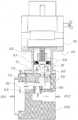
도 6은 본 발명에 따른 일 실시예의 무 접점 위치 감지센서(21)를 내장한 스텝핑 또는 D.C 모터(30)와 일체의 구조로 구성된 모터 구동식 유량 제어 장치(100) 장치의 구조를 도시한 단면도이다.6 is a cross-sectional view showing the structure of a motor-driven flow
무 접점 위치 감지센서(21)를 내장한 스텝핑 또는 D.C 모터(30)와 일체의 구조로 구성된 모터 구동식 유량 제어 장치(100)는 도 6을 참조하면 스텝핑 또는 D.C 모터(30)를 중심으로 모터의 하측으로는 모터축(50)이 위치한다. 모터축의 외경은 벨로우즈(61)로 연결된 커플링(60)의 상측 내경과 연결되고, 벨로우즈(61)로 연결된 커플링(60)의 하측 내경에는 플러그(PLUG) 축(80)의 상측 외경과 결합 되고, 플러그(PLUG) 축의 360°회전을 원활히 하기 위해 베어링(73)과 유체의 누설을 방지하기 위한 내경 부(71),외경 부(72)에 오 링을 구비한 브라켓트(70)를 플러그(PLUG) 축(80)의 하측 외경 부와 결합하고, 플러그(PLUG) 축의 회전각과 회전량을 자석과 전자회로로 절대 위치를 감지하는 무 접점 위치 감지센서(21)가 플러그(PLUG) 축의 상측 외경 부에 위치하고, 또한 상기의 회전하는 회전체의 외부 차단 구조를 가지는 하우징(40)은 상기의 구동 모터(30)와 유체가 공급되는 유체 통로에 설치된 모터 구동식 유량 제어 장치(100)를 연결하는 것을 포함하고, 상기의 플러그(PLUG) 축(80)과 편심 축을 가지는 일체형 구조로 구성된 플러그(PLUG)(81), 상기의 편심 축을 가지고 360°회전하는 플러그(PLUG)(81)의 하부 밑면과 평행하게 위치하는 상부 측에 오 링(91)을 내장하는 구조를 가지는 오리피스(90)로 구성되어 있다.Referring to FIG. 6, a motor-driven
스텝핑 또는 D.C 모터(30)의 모터축(50)과 일체로 구성 연결된 커플링(60), 벨로우즈(61), 플러그(PLUG) 축(80)과 플러그(PLUG)(81)는 모터(30)의 360°회전에 의해 동일한 방향으로 회전하게 된다.The
도 7은 본 발명의 실시예에 따른 플러그(PLUG)(81)와 일체로 구성된 플러그(PLUG) 축(80)의 구조를 도시한 단면도이다. 도 7(a)는 플러그와 플러그 축의 평면도이고, 도 7(b)는 플러그와 플러그 축의 정면도이고, 도 7(c)는 플러그와 플러그 축의 저면도이다. 플러그(PLUG) 축(80)의 상측 외경은 도 6를 참조하면 스텝핑 또는 D.C 모터(30)의 모터 축(50)과 벨로우즈(61)와 일체로 구성된 커플링(60)의 내경과 연결되고, 플러그(PLUG) 축(80)의 하측에는 편심 축의 특성을 이루는 일체형의 하부 밑면이 평평한 플러그(PLUG)(81)로 구성하는 구조로 되어있다.
7 is a cross-sectional view showing the structure of a
도 8은 본 발명의 실시예에 따른 오 링(91)을 내장한 오리피스(90)의 구조를 도시한 단면도이다. 도 8(a)는 오 링을 내장한 오리피스의 평면도이고, 도 8(b)는 오 링을 내장한 오리피스의 절단면도이고, 도 8(c)는 오 링을 내장한 오리피스의 저면도이다. 오리피스(90)는 도 7의 360°회전하는 플러그(80) 축과 편심 축을 이루는 플러그(81)의 밑면과 오리피스(90)의 상측 부 오 링(91)과 평행하게 위치하여 결합되어 오리피스의 구멍(93)을 개폐하여 유체의 흐름량을 제어하는 것을 특징으로 하는 구조로 되어 있다. 또한 오리피스(90)의 구멍 크기는 유체의 기종과 유체의 흐름량 등 작동 조건의 변화에 따라 유동적으로 선택하여 교체할 수 있게 되어 있고, 유량 제어 장치와 결합 시 유체의 누설을 방지하기 위해 오리피스 하부 외경 부에 오 링(92)이 위치하는 구조로 되어있다.8 is a cross-sectional view showing the structure of an
도 9는 도 7의 플러그(PLUG)(81)와 일체로 구성된 플러그(PLUG) 축(80)과 도 8의 오 링(91)을 내장한 오리피스(90)와 결합하여 플러그(PLUG) 축(80)의 회전각 또는 회전량의 정도에 따른 오 링 내장형 오리피스 구멍(93)의 개폐를 개략적으로 도시한 단면도이다. 도 9(a)의 플러그(PLUG)(81)와 일체로 구성된 플러그(PLUG) 축(80)은 스텝핑 또는 D.C 모터의 360°회전에 대해 동일한 방향으로 회전하게 된다. 도 9(b)에서처럼 플러그(PLUG)(81)의 회전각이 0°또는 360°일 경우 오리피스 구멍의 개폐 정도는 완전히 개방되며, 도 9(e)에서는 플러그(PLUG)(81)의 회전각이 180°일 때 오리피스 구멍의 개폐 정도가 완전히 닫혀 지는 것을 나타내고 있다. 상기에서 도 9(c),(d),(f),(g)처럼 플러그(PLUG)(81)의 회전각이 0 ~ 360 °로 회전하며, 제어되는 회전각에 따라 오리피스 구멍의 개폐 정도가 미세한 차이를 이루어 유체의 흐름량을 정밀 제어하는 것이 가능하게 되었다.
9 is a plan view showing a
상기에서 본 발명의 바람직한 실시예가 특정 용어들을 사용하여 설명 및 도시되었지만 그러한 용어는 오로지 본 발명을 명확히 설명하기 위한 것일 뿐이며, 본 발명의 실시예 및 기술된 용어는 다음의 청구범위의 기술적 사상 및 범위로부터이탈되지 않고서 여러가지 변경 및 변화가 가해질 수 있는 것은 자명한 일이다. 이와 같은 변형된 실시예들은 본 발명의 사상 및 범위로부터 개별적으로 이해되어져서는 안되며, 본 발명의 청구범위 안에 속한다고 해야 할 것이다.
While the preferred embodiments of the present invention have been described and illustrated above using specific terms, such terms are used only for the purpose of clarifying the invention, and it is to be understood that the embodiment It will be obvious that various changes and modifications can be made without departing from the spirit and scope of the invention. Such modified embodiments should not be understood individually from the spirit and scope of the present invention, but should be regarded as being within the scope of the claims of the present invention.
10; 본 발명의 실시예에 따른 통합 전자회로 제어기
10a: 본 발명의 실시예에 따른 유량 설정회로
10b: 본 발명의 실시예에 따른 모터 구동회로
10c: 본 발명의 실시예에 따른 유량 미분 제어회로(Differential)
10d: 본 발명의 실시예에 따른 유량 적분 제어회로(Proportional Integral)
10e: 본 발명의 실시예에 따른 외부 입력 커넥터
10f: 본 발명의 실시예에 따른 프로그램 입력 장치
20: 본 발명의 실시예에 따른 유량 측정 센서
21: 본 발명의 실시예에 따른 무접점 위치 감지센서
30: 본 발명의 실시예에 따른 스텝핑 또는 D.C 모터
40: 본 발명의 실시예에 따른 회전체 하우징
50: 본 발명의 실시예에 따른 모터 축
60: 본 발명의 실시예에 따른 커플링
61: 본 발명의 실시예에 따른 벨로우즈
70: 본 발명의 실시예에 따른 베어링 브라켓트
71: 본 발명의 실시예에 따른 브라켓트 내경 오 링
72: 본 발명의 실시예에 따른 브라켓트 외경 오 링
73: 본 발명의 실시예에 따른 베어링
80: 본 발명의 실시예에 따른 플러그(PLUG) 축
81: 본 발명의 실시예에 따른 플러그(PLUG)
90: 본 발명의 실시예에 따른 오리피스
91: 본 발명의 실시예에 따른 오리피스 상측 오 링
92: 본 발명의 실시예에 따른 오리피스 하측 오 링
93: 본 발명의 실시예에 따른 오리피스 구멍
100: 본 발명의 실시예에 따른 모터 구동식 유량 제어 장치
101: 유체 통로 연결 유입구
102: 유체 통로 연결 유출구
103: 유체(기체 또는 액체)10; The integrated electronic circuit controller < RTI ID = 0.0 >
10a: Flow rate setting circuit according to the embodiment of the present invention
10b: a motor driving circuit according to an embodiment of the present invention
10c: a flow differential control circuit (Differential) according to an embodiment of the present invention;
10d: a flow integral control circuit (Proportional Integral) according to an embodiment of the present invention;
10e: an external input connector according to an embodiment of the present invention
10f: a program input device according to an embodiment of the present invention
20: A flow measurement sensor according to an embodiment of the present invention
21: The contactless position sensor according to the embodiment of the present invention
30: Stepping or DC motor according to an embodiment of the present invention
40: rotator housing according to the embodiment of the present invention
50: motor shaft according to the embodiment of the present invention
60: coupling according to an embodiment of the present invention
61: The bellows according to the embodiment of the present invention
70: A bearing bracket according to an embodiment of the present invention
71: Bracket inner diameter O ring according to the embodiment of the present invention
72: Bracket outer diameter O ring according to the embodiment of the present invention
73: Bearing according to an embodiment of the present invention
80: PLUG shaft according to the embodiment of the present invention
81: PLUG according to the embodiment of the present invention;
90: Orifice according to an embodiment of the present invention
91: The upper orifice of the orifice according to the embodiment of the present invention
92: The orifice lower side ring according to the embodiment of the present invention
93: The orifice hole according to the embodiment of the present invention
100: motor-driven flow rate control device according to an embodiment of the present invention
101: Fluid passage connection inlet
102: fluid passage connection outlet
103: fluid (gas or liquid)
Claims (9)
Translated fromKorean상기 유입구 측에 설치되며 유체 흐름량을 측정한 후 전기적 신호로 변환하여 출력하는 유량측정센서와,
회전력을 제공하는 모터축을 구비하는 상기 모터와,
상측 내경은 상기 모터축의 외경과 연결되는 상측 커플링과, 상기 상측 커플링과 연결되는 벨로우즈와, 상기 벨로우즈와 연결되는 하측 커플링과,
상측 외경이 상기 하측 커플링의 내경과 연결되는 플러그(PLUG) 축과, 상기 플러그 축과 일체로 형성되며 상기 플러그(PLUG) 축의 하측에 형성되는 편심 축을 구비하는 플러그(PLUG), 및
상기 플러그의 편심축 하부의 상기 유체 통로 상에 설치되는 오리피스를 포함하는 것을 특징으로 하는 유체 정밀 질량 유량제어장치.
A fluid precision mass flow controller for precisely controlling an amount of fluid flowing in a fluid passage between an inlet port and an outlet port using a motor,
A flow rate measuring sensor provided on the inlet side and measuring a flow rate of the fluid, converting the flow rate into an electrical signal,
Said motor having a motor shaft providing a rotational force,
An upper coupling having an upper inner diameter connected to an outer diameter of the motor shaft, a bellows connected to the upper coupling, a lower coupling connected to the bellows,
A PLUG shaft having an upper outer diameter connected to the inner diameter of the lower coupling and an eccentric shaft integrally formed with the plug shaft and formed below the shaft of the plug,
And an orifice provided on the fluid passage below the eccentric shaft of the plug.
상기 플러그(PLUG) 축의 회전각 또는 회전량의 절대 위치를 제어하는 제어 신호를 공급하고, 상기 플러그(PLUG) 축의 회전각 또는 회전량의 절대 위치를 감지하고 이를 피드백하는 무 접점 위치 감지 센서와,
상기 유량측정센서로부터 입력되는 전기적 신호와, 상기 무 접점 위치 감지 센서로부터 피드백되는 회전각 또는 회전량의 절대 위치와, 기 설정된 유체 흐름량을 비교한 후 상기 모터를 구동시키기 위한 전기적 신호를 출력하는 통합 전자 회로 제어기를 더 포함하는 것을 특징으로 하는 유체 정밀 질량 유량제어장치.
The method according to claim 1,
A contactless position detecting sensor for supplying a control signal for controlling an absolute position of the rotation angle or the rotation amount of the PLUG shaft and detecting and feeding back the absolute position of the rotation angle or the rotation amount of the PLUG axis,
An electric signal input from the flow rate measuring sensor, an absolute position of a rotation angle or a rotation amount fed back from the contactless position sensing sensor, and an integrated signal outputting an electrical signal for driving the motor after comparing the predetermined fluid flow amount Further comprising an electronic circuit controller.
상기 오리피스는 상기 편심 축과 맞닿는 영역에 설치되는 오 링을 갖는 오리피스 구멍을 구비하고, 상기 플러그의 편심 축이 0~360°회전하면서 상기 오리피스 구멍의 개폐 정도를 조절하는 것을 특징으로 하는 유체 정밀 질량 유량제어장치.
3. The method according to claim 1 or 2,
Wherein the orifice has an orifice hole having an O-ring provided in an area in contact with the eccentric shaft, and the eccentric axis of the plug rotates 0 to 360 degrees to adjust the opening / closing degree of the orifice hole. Flow control device.
상기 통합 전자 회로 제어기에는 유량 미분 제어회로가 구비되고, 상기 유량 미분 제어회로는 상기 유량측정센서로부터 입력되는 전기적 신호와 상기 기 설정된 유량값을 비교하여 그 차이만큼 산출된 값을 상기 무 접점 위치 감지센서에서 피드백되는 회전각 또는 회전량의 절대 위치보다 우선적으로 이용하는 것을 특징으로 하는 유체 정밀 질량 유량제어장치.
3. The method of claim 2,
Wherein the integrated electronic circuit controller is provided with a flow rate differential control circuit which compares an electrical signal inputted from the flow rate measuring sensor with the predetermined flow rate value and outputs a value calculated by the difference to the non- Wherein the absolute value of the rotation angle or the amount of rotation fed back from the sensor is preferentially used.
상기 통합 전자 회로 제어기에는 상기 유량 미분 제어회로에 종속되어 작동되는 유량 적분 제어회로를 더 구비하는 것을 특징으로 하는 유체 정밀 질량 유량제어장치.
6. The method of claim 5,
Wherein the integrated electronic circuit controller further comprises a flow integration control circuit which is operated depending on the flow differential control circuit.
상기 모터 축, 상기 상측 커플링과, 상기 벨로우즈, 상기 하측 커플링 및 상기 플러그 축의 일부를 외부로부터 보호하는 회전체 하우징을 더 포함하는 것을 특징으로 하는 유체 정밀 질량 유량제어장치.
The method according to claim 1,
Further comprising a rotating housing for protecting the motor shaft, the upper coupling, the bellows, the lower coupling, and a part of the plug shaft from the outside.
상기 하측 커플링 하부와 상기 편심 축 사이에 위치하는 상기 플러그 축의 일부 외경과 결합되는 베어링과, 상기 플러그 축 외경에 삽입 설치되는 오 링을 구비하고, 상기 베어링 및 상기 오링을 지지하는 베어링 브라켓트를 더 포함하는 것을 특징으로 하는 유체 정밀 질량 유량제어장치.
The method according to claim 1,
A bearing which is engaged with a part of the outside diameter of the plug shaft located between the lower coupling lower part and the eccentric shaft and an O-ring inserted into the outer diameter of the plug shaft, and the bearing bracket supporting the bearing and the O- And the flow rate of the fluid.
상기 통합 전자 회로 제어기에는 상기 유량측정센서에서 측정된 유체 흐름량에 대한 전기적 신호와 상기 기 설정된 유체 흐름량과 비교한 후 차이값을 산출하는 유량 설정회로 및 상기 모터를 구동시키기 위한 전기적 신호를 출력하는 모터 구동회로를 포함하고,
상기 무 접점 위치 감지 센서는 상기 모터 구동 회로로부터 입력되는 전기적 신호에 따라 상기 플러그(PLUG) 축의 회전각 또는 회전량의 절대 위치를 제어하기 위한 제어 신호를 출력하는 것을 특징으로 하는 유체 정밀 질량 유량제어장치.3. The method of claim 2,
The integrated electronic circuit controller includes a flow rate setting circuit for calculating an electrical signal for the fluid flow rate measured by the flow rate measuring sensor and a difference value after comparing the predetermined flow rate with the predetermined flow rate and a motor for outputting an electric signal for driving the motor A driving circuit,
Wherein the contactless position sensing sensor outputs a control signal for controlling an absolute position of a rotation angle or a rotation amount of the plug shaft according to an electrical signal input from the motor driving circuit. Device.
Priority Applications (1)
| Application Number | Priority Date | Filing Date | Title |
|---|---|---|---|
| KR1020130037244AKR101455928B1 (en) | 2013-04-05 | 2013-04-05 | Mass flow controller with motor driving circuit |
Applications Claiming Priority (1)
| Application Number | Priority Date | Filing Date | Title |
|---|---|---|---|
| KR1020130037244AKR101455928B1 (en) | 2013-04-05 | 2013-04-05 | Mass flow controller with motor driving circuit |
Publications (2)
| Publication Number | Publication Date |
|---|---|
| KR20140121063A KR20140121063A (en) | 2014-10-15 |
| KR101455928B1true KR101455928B1 (en) | 2014-10-31 |
Family
ID=51992712
Family Applications (1)
| Application Number | Title | Priority Date | Filing Date |
|---|---|---|---|
| KR1020130037244AExpired - Fee RelatedKR101455928B1 (en) | 2013-04-05 | 2013-04-05 | Mass flow controller with motor driving circuit |
Country Status (1)
| Country | Link |
|---|---|
| KR (1) | KR101455928B1 (en) |
Cited By (2)
| Publication number | Priority date | Publication date | Assignee | Title |
|---|---|---|---|---|
| KR200489094Y1 (en)* | 2018-12-31 | 2019-04-30 | (주)아토벡 | Gas Flow Control Apparatus |
| WO2022098251A1 (en) | 2020-11-03 | 2022-05-12 | Institutul Naţional De Cercetare Dezvoltare Pentru Inginerie Electrică Icpe-Ca | Equipment for continuous adjustment of liquid flow, with direct electric drive of the element which performs the modification of the flow section |
Citations (4)
| Publication number | Priority date | Publication date | Assignee | Title |
|---|---|---|---|---|
| US20040187927A1 (en)* | 2003-03-28 | 2004-09-30 | Samsung Electronics Co., Ltd. | Mass flow controller |
| KR20070026232A (en)* | 2005-09-01 | 2007-03-08 | 에스엠씨 가부시키 가이샤 | Flow control valve |
| KR20080077597A (en)* | 2006-03-02 | 2008-08-25 | 에스엠씨 가부시키 가이샤 | Flow control device |
| KR100875813B1 (en)* | 2000-09-20 | 2008-12-26 | 가부시키가이샤 호리바 에스텍 | Fluid Mass Flow Controller and Its Operation Method |
- 2013
- 2013-04-05KRKR1020130037244Apatent/KR101455928B1/ennot_activeExpired - Fee Related
Patent Citations (4)
| Publication number | Priority date | Publication date | Assignee | Title |
|---|---|---|---|---|
| KR100875813B1 (en)* | 2000-09-20 | 2008-12-26 | 가부시키가이샤 호리바 에스텍 | Fluid Mass Flow Controller and Its Operation Method |
| US20040187927A1 (en)* | 2003-03-28 | 2004-09-30 | Samsung Electronics Co., Ltd. | Mass flow controller |
| KR20070026232A (en)* | 2005-09-01 | 2007-03-08 | 에스엠씨 가부시키 가이샤 | Flow control valve |
| KR20080077597A (en)* | 2006-03-02 | 2008-08-25 | 에스엠씨 가부시키 가이샤 | Flow control device |
Cited By (2)
| Publication number | Priority date | Publication date | Assignee | Title |
|---|---|---|---|---|
| KR200489094Y1 (en)* | 2018-12-31 | 2019-04-30 | (주)아토벡 | Gas Flow Control Apparatus |
| WO2022098251A1 (en) | 2020-11-03 | 2022-05-12 | Institutul Naţional De Cercetare Dezvoltare Pentru Inginerie Electrică Icpe-Ca | Equipment for continuous adjustment of liquid flow, with direct electric drive of the element which performs the modification of the flow section |
Also Published As
| Publication number | Publication date |
|---|---|
| KR20140121063A (en) | 2014-10-15 |
Similar Documents
| Publication | Publication Date | Title |
|---|---|---|
| EP1553339B1 (en) | Flow control valve and flow control device | |
| US7255012B2 (en) | Process fluid flow device with variable orifice | |
| JP6138718B2 (en) | Control unit for mixed faucet and temperature control device for mixed faucet | |
| WO2006046612A1 (en) | Flow control valve | |
| CN109863336B (en) | Flow control valve and fluid control device using same | |
| US20150346733A1 (en) | Gaseous fuel control device for engines | |
| EP2028455A3 (en) | Force balanced impeller flow meter for mass flow rate control | |
| US8887549B2 (en) | Valve leakby diagnostics | |
| JP6122541B1 (en) | Two-way valve for flow control and temperature control device using the same | |
| JP6640510B2 (en) | Flow control valve | |
| KR101455928B1 (en) | Mass flow controller with motor driving circuit | |
| CN111712594B (en) | Hydraulic controls for liquid conducting appliances and systems | |
| CN111051752A (en) | Flow control unit | |
| JP7104987B2 (en) | Flow control valve and fluid control device using the same | |
| US9861991B2 (en) | Control system for a decanter centrifuge | |
| JP4126225B2 (en) | Control method of flow control valve | |
| KR20040081491A (en) | Flow regulating valve, flow rate measuring device, flow control device, and flow rate measuring method | |
| KR101508498B1 (en) | Mass flow controller with motor driving circuit | |
| WO2019049290A1 (en) | Flowmeter | |
| KR101706602B1 (en) | Apparatus of controlling for flow regulating valve by stepping control | |
| CN113757412A (en) | Thermostatic valve and water heater | |
| JP2007278514A (en) | Control method of flow control valve | |
| CN207473420U (en) | A kind of electronic flowmeter | |
| CN108779868A (en) | Valve device | |
| KR102767698B1 (en) | Apparatus for opening and closing a flow path and method for controlling the same |
Legal Events
| Date | Code | Title | Description |
|---|---|---|---|
| PA0109 | Patent application | St.27 status event code:A-0-1-A10-A12-nap-PA0109 | |
| PA0201 | Request for examination | St.27 status event code:A-1-2-D10-D11-exm-PA0201 | |
| D13-X000 | Search requested | St.27 status event code:A-1-2-D10-D13-srh-X000 | |
| D14-X000 | Search report completed | St.27 status event code:A-1-2-D10-D14-srh-X000 | |
| PE0902 | Notice of grounds for rejection | St.27 status event code:A-1-2-D10-D21-exm-PE0902 | |
| T11-X000 | Administrative time limit extension requested | St.27 status event code:U-3-3-T10-T11-oth-X000 | |
| E13-X000 | Pre-grant limitation requested | St.27 status event code:A-2-3-E10-E13-lim-X000 | |
| P11-X000 | Amendment of application requested | St.27 status event code:A-2-2-P10-P11-nap-X000 | |
| P13-X000 | Application amended | St.27 status event code:A-2-2-P10-P13-nap-X000 | |
| PG1501 | Laying open of application | St.27 status event code:A-1-1-Q10-Q12-nap-PG1501 | |
| E701 | Decision to grant or registration of patent right | ||
| PE0701 | Decision of registration | St.27 status event code:A-1-2-D10-D22-exm-PE0701 | |
| GRNT | Written decision to grant | ||
| PR0701 | Registration of establishment | St.27 status event code:A-2-4-F10-F11-exm-PR0701 | |
| PR1002 | Payment of registration fee | St.27 status event code:A-2-2-U10-U11-oth-PR1002 Fee payment year number:1 | |
| PG1601 | Publication of registration | St.27 status event code:A-4-4-Q10-Q13-nap-PG1601 | |
| P22-X000 | Classification modified | St.27 status event code:A-4-4-P10-P22-nap-X000 | |
| FPAY | Annual fee payment | Payment date:20170904 Year of fee payment:4 | |
| PR1001 | Payment of annual fee | St.27 status event code:A-4-4-U10-U11-oth-PR1001 Fee payment year number:4 | |
| PR1001 | Payment of annual fee | St.27 status event code:A-4-4-U10-U11-oth-PR1001 Fee payment year number:5 | |
| PC1903 | Unpaid annual fee | St.27 status event code:A-4-4-U10-U13-oth-PC1903 Not in force date:20191023 Payment event data comment text:Termination Category : DEFAULT_OF_REGISTRATION_FEE | |
| K11-X000 | Ip right revival requested | St.27 status event code:A-6-4-K10-K11-oth-X000 | |
| PC1903 | Unpaid annual fee | St.27 status event code:N-4-6-H10-H13-oth-PC1903 Ip right cessation event data comment text:Termination Category : DEFAULT_OF_REGISTRATION_FEE Not in force date:20191023 | |
| PR0401 | Registration of restoration | St.27 status event code:A-6-4-K10-K13-oth-PR0401 | |
| R401 | Registration of restoration | ||
| PR1001 | Payment of annual fee | St.27 status event code:A-4-4-U10-U11-oth-PR1001 Fee payment year number:6 | |
| PR1001 | Payment of annual fee | St.27 status event code:A-4-4-U10-U11-oth-PR1001 Fee payment year number:7 | |
| PR1001 | Payment of annual fee | St.27 status event code:A-4-4-U10-U11-oth-PR1001 Fee payment year number:8 | |
| PR1001 | Payment of annual fee | St.27 status event code:A-4-4-U10-U11-oth-PR1001 Fee payment year number:9 | |
| PR1001 | Payment of annual fee | St.27 status event code:A-4-4-U10-U11-oth-PR1001 Fee payment year number:10 | |
| PR1001 | Payment of annual fee | St.27 status event code:A-4-4-U10-U11-oth-PR1001 Fee payment year number:11 |