KR101453961B1 - adjustable intervertebral implant - Google Patents
adjustable intervertebral implantDownload PDFInfo
- Publication number
- KR101453961B1 KR101453961B1KR1020097015899AKR20097015899AKR101453961B1KR 101453961 B1KR101453961 B1KR 101453961B1KR 1020097015899 AKR1020097015899 AKR 1020097015899AKR 20097015899 AKR20097015899 AKR 20097015899AKR 101453961 B1KR101453961 B1KR 101453961B1
- Authority
- KR
- South Korea
- Prior art keywords
- body member
- ratchet
- ring
- ratcheting
- drive ring
- Prior art date
- Legal status (The legal status is an assumption and is not a legal conclusion. Google has not performed a legal analysis and makes no representation as to the accuracy of the status listed.)
- Expired - Fee Related
Links
Images


Classifications
- A—HUMAN NECESSITIES
- A61—MEDICAL OR VETERINARY SCIENCE; HYGIENE
- A61F—FILTERS IMPLANTABLE INTO BLOOD VESSELS; PROSTHESES; DEVICES PROVIDING PATENCY TO, OR PREVENTING COLLAPSING OF, TUBULAR STRUCTURES OF THE BODY, e.g. STENTS; ORTHOPAEDIC, NURSING OR CONTRACEPTIVE DEVICES; FOMENTATION; TREATMENT OR PROTECTION OF EYES OR EARS; BANDAGES, DRESSINGS OR ABSORBENT PADS; FIRST-AID KITS
- A61F2/00—Filters implantable into blood vessels; Prostheses, i.e. artificial substitutes or replacements for parts of the body; Appliances for connecting them with the body; Devices providing patency to, or preventing collapsing of, tubular structures of the body, e.g. stents
- A61F2/02—Prostheses implantable into the body
- A61F2/30—Joints
- A61F2/44—Joints for the spine, e.g. vertebrae, spinal discs
- A—HUMAN NECESSITIES
- A61—MEDICAL OR VETERINARY SCIENCE; HYGIENE
- A61B—DIAGNOSIS; SURGERY; IDENTIFICATION
- A61B17/00—Surgical instruments, devices or methods
- A61B17/56—Surgical instruments or methods for treatment of bones or joints; Devices specially adapted therefor
- A61B17/58—Surgical instruments or methods for treatment of bones or joints; Devices specially adapted therefor for osteosynthesis, e.g. bone plates, screws or setting implements
- A61B17/68—Internal fixation devices, including fasteners and spinal fixators, even if a part thereof projects from the skin
- A61B17/70—Spinal positioners or stabilisers, e.g. stabilisers comprising fluid filler in an implant
- A—HUMAN NECESSITIES
- A61—MEDICAL OR VETERINARY SCIENCE; HYGIENE
- A61F—FILTERS IMPLANTABLE INTO BLOOD VESSELS; PROSTHESES; DEVICES PROVIDING PATENCY TO, OR PREVENTING COLLAPSING OF, TUBULAR STRUCTURES OF THE BODY, e.g. STENTS; ORTHOPAEDIC, NURSING OR CONTRACEPTIVE DEVICES; FOMENTATION; TREATMENT OR PROTECTION OF EYES OR EARS; BANDAGES, DRESSINGS OR ABSORBENT PADS; FIRST-AID KITS
- A61F2/00—Filters implantable into blood vessels; Prostheses, i.e. artificial substitutes or replacements for parts of the body; Appliances for connecting them with the body; Devices providing patency to, or preventing collapsing of, tubular structures of the body, e.g. stents
- A61F2/02—Prostheses implantable into the body
- A61F2/30—Joints
- A61F2/44—Joints for the spine, e.g. vertebrae, spinal discs
- A61F2/4455—Joints for the spine, e.g. vertebrae, spinal discs for the fusion of spinal bodies, e.g. intervertebral fusion of adjacent spinal bodies, e.g. fusion cages
- A61F2/4465—Joints for the spine, e.g. vertebrae, spinal discs for the fusion of spinal bodies, e.g. intervertebral fusion of adjacent spinal bodies, e.g. fusion cages having a circular or kidney shaped cross-section substantially perpendicular to the axis of the spine
- A—HUMAN NECESSITIES
- A61—MEDICAL OR VETERINARY SCIENCE; HYGIENE
- A61F—FILTERS IMPLANTABLE INTO BLOOD VESSELS; PROSTHESES; DEVICES PROVIDING PATENCY TO, OR PREVENTING COLLAPSING OF, TUBULAR STRUCTURES OF THE BODY, e.g. STENTS; ORTHOPAEDIC, NURSING OR CONTRACEPTIVE DEVICES; FOMENTATION; TREATMENT OR PROTECTION OF EYES OR EARS; BANDAGES, DRESSINGS OR ABSORBENT PADS; FIRST-AID KITS
- A61F2/00—Filters implantable into blood vessels; Prostheses, i.e. artificial substitutes or replacements for parts of the body; Appliances for connecting them with the body; Devices providing patency to, or preventing collapsing of, tubular structures of the body, e.g. stents
- A61F2/02—Prostheses implantable into the body
- A61F2/28—Bones
- A61F2002/2835—Bone graft implants for filling a bony defect or an endoprosthesis cavity, e.g. by synthetic material or biological material
- A—HUMAN NECESSITIES
- A61—MEDICAL OR VETERINARY SCIENCE; HYGIENE
- A61F—FILTERS IMPLANTABLE INTO BLOOD VESSELS; PROSTHESES; DEVICES PROVIDING PATENCY TO, OR PREVENTING COLLAPSING OF, TUBULAR STRUCTURES OF THE BODY, e.g. STENTS; ORTHOPAEDIC, NURSING OR CONTRACEPTIVE DEVICES; FOMENTATION; TREATMENT OR PROTECTION OF EYES OR EARS; BANDAGES, DRESSINGS OR ABSORBENT PADS; FIRST-AID KITS
- A61F2/00—Filters implantable into blood vessels; Prostheses, i.e. artificial substitutes or replacements for parts of the body; Appliances for connecting them with the body; Devices providing patency to, or preventing collapsing of, tubular structures of the body, e.g. stents
- A61F2/02—Prostheses implantable into the body
- A61F2/30—Joints
- A61F2002/30001—Additional features of subject-matter classified in A61F2/28, A61F2/30 and subgroups thereof
- A61F2002/30003—Material related properties of the prosthesis or of a coating on the prosthesis
- A61F2002/30004—Material related properties of the prosthesis or of a coating on the prosthesis the prosthesis being made from materials having different values of a given property at different locations within the same prosthesis
- A—HUMAN NECESSITIES
- A61—MEDICAL OR VETERINARY SCIENCE; HYGIENE
- A61F—FILTERS IMPLANTABLE INTO BLOOD VESSELS; PROSTHESES; DEVICES PROVIDING PATENCY TO, OR PREVENTING COLLAPSING OF, TUBULAR STRUCTURES OF THE BODY, e.g. STENTS; ORTHOPAEDIC, NURSING OR CONTRACEPTIVE DEVICES; FOMENTATION; TREATMENT OR PROTECTION OF EYES OR EARS; BANDAGES, DRESSINGS OR ABSORBENT PADS; FIRST-AID KITS
- A61F2/00—Filters implantable into blood vessels; Prostheses, i.e. artificial substitutes or replacements for parts of the body; Appliances for connecting them with the body; Devices providing patency to, or preventing collapsing of, tubular structures of the body, e.g. stents
- A61F2/02—Prostheses implantable into the body
- A61F2/30—Joints
- A61F2002/30001—Additional features of subject-matter classified in A61F2/28, A61F2/30 and subgroups thereof
- A61F2002/30108—Shapes
- A61F2002/3011—Cross-sections or two-dimensional shapes
- A61F2002/30112—Rounded shapes, e.g. with rounded corners
- A61F2002/30133—Rounded shapes, e.g. with rounded corners kidney-shaped or bean-shaped
- A—HUMAN NECESSITIES
- A61—MEDICAL OR VETERINARY SCIENCE; HYGIENE
- A61F—FILTERS IMPLANTABLE INTO BLOOD VESSELS; PROSTHESES; DEVICES PROVIDING PATENCY TO, OR PREVENTING COLLAPSING OF, TUBULAR STRUCTURES OF THE BODY, e.g. STENTS; ORTHOPAEDIC, NURSING OR CONTRACEPTIVE DEVICES; FOMENTATION; TREATMENT OR PROTECTION OF EYES OR EARS; BANDAGES, DRESSINGS OR ABSORBENT PADS; FIRST-AID KITS
- A61F2/00—Filters implantable into blood vessels; Prostheses, i.e. artificial substitutes or replacements for parts of the body; Appliances for connecting them with the body; Devices providing patency to, or preventing collapsing of, tubular structures of the body, e.g. stents
- A61F2/02—Prostheses implantable into the body
- A61F2/30—Joints
- A61F2002/30001—Additional features of subject-matter classified in A61F2/28, A61F2/30 and subgroups thereof
- A61F2002/30108—Shapes
- A61F2002/30199—Three-dimensional shapes
- A61F2002/302—Three-dimensional shapes toroidal, e.g. rings
- A—HUMAN NECESSITIES
- A61—MEDICAL OR VETERINARY SCIENCE; HYGIENE
- A61F—FILTERS IMPLANTABLE INTO BLOOD VESSELS; PROSTHESES; DEVICES PROVIDING PATENCY TO, OR PREVENTING COLLAPSING OF, TUBULAR STRUCTURES OF THE BODY, e.g. STENTS; ORTHOPAEDIC, NURSING OR CONTRACEPTIVE DEVICES; FOMENTATION; TREATMENT OR PROTECTION OF EYES OR EARS; BANDAGES, DRESSINGS OR ABSORBENT PADS; FIRST-AID KITS
- A61F2/00—Filters implantable into blood vessels; Prostheses, i.e. artificial substitutes or replacements for parts of the body; Appliances for connecting them with the body; Devices providing patency to, or preventing collapsing of, tubular structures of the body, e.g. stents
- A61F2/02—Prostheses implantable into the body
- A61F2/30—Joints
- A61F2002/30001—Additional features of subject-matter classified in A61F2/28, A61F2/30 and subgroups thereof
- A61F2002/30108—Shapes
- A61F2002/30199—Three-dimensional shapes
- A61F2002/30224—Three-dimensional shapes cylindrical
- A61F2002/30235—Three-dimensional shapes cylindrical tubular, e.g. sleeves
- A—HUMAN NECESSITIES
- A61—MEDICAL OR VETERINARY SCIENCE; HYGIENE
- A61F—FILTERS IMPLANTABLE INTO BLOOD VESSELS; PROSTHESES; DEVICES PROVIDING PATENCY TO, OR PREVENTING COLLAPSING OF, TUBULAR STRUCTURES OF THE BODY, e.g. STENTS; ORTHOPAEDIC, NURSING OR CONTRACEPTIVE DEVICES; FOMENTATION; TREATMENT OR PROTECTION OF EYES OR EARS; BANDAGES, DRESSINGS OR ABSORBENT PADS; FIRST-AID KITS
- A61F2/00—Filters implantable into blood vessels; Prostheses, i.e. artificial substitutes or replacements for parts of the body; Appliances for connecting them with the body; Devices providing patency to, or preventing collapsing of, tubular structures of the body, e.g. stents
- A61F2/02—Prostheses implantable into the body
- A61F2/30—Joints
- A61F2002/30001—Additional features of subject-matter classified in A61F2/28, A61F2/30 and subgroups thereof
- A61F2002/30316—The prosthesis having different structural features at different locations within the same prosthesis; Connections between prosthetic parts; Special structural features of bone or joint prostheses not otherwise provided for
- A61F2002/30329—Connections or couplings between prosthetic parts, e.g. between modular parts; Connecting elements
- A61F2002/30331—Connections or couplings between prosthetic parts, e.g. between modular parts; Connecting elements made by longitudinally pushing a protrusion into a complementarily-shaped recess, e.g. held by friction fit
- A61F2002/30362—Connections or couplings between prosthetic parts, e.g. between modular parts; Connecting elements made by longitudinally pushing a protrusion into a complementarily-shaped recess, e.g. held by friction fit with possibility of relative movement between the protrusion and the recess
- A61F2002/30369—Limited lateral translation of the protrusion within a larger recess
- A—HUMAN NECESSITIES
- A61—MEDICAL OR VETERINARY SCIENCE; HYGIENE
- A61F—FILTERS IMPLANTABLE INTO BLOOD VESSELS; PROSTHESES; DEVICES PROVIDING PATENCY TO, OR PREVENTING COLLAPSING OF, TUBULAR STRUCTURES OF THE BODY, e.g. STENTS; ORTHOPAEDIC, NURSING OR CONTRACEPTIVE DEVICES; FOMENTATION; TREATMENT OR PROTECTION OF EYES OR EARS; BANDAGES, DRESSINGS OR ABSORBENT PADS; FIRST-AID KITS
- A61F2/00—Filters implantable into blood vessels; Prostheses, i.e. artificial substitutes or replacements for parts of the body; Appliances for connecting them with the body; Devices providing patency to, or preventing collapsing of, tubular structures of the body, e.g. stents
- A61F2/02—Prostheses implantable into the body
- A61F2/30—Joints
- A61F2002/30001—Additional features of subject-matter classified in A61F2/28, A61F2/30 and subgroups thereof
- A61F2002/30316—The prosthesis having different structural features at different locations within the same prosthesis; Connections between prosthetic parts; Special structural features of bone or joint prostheses not otherwise provided for
- A61F2002/30329—Connections or couplings between prosthetic parts, e.g. between modular parts; Connecting elements
- A61F2002/30405—Connections or couplings between prosthetic parts, e.g. between modular parts; Connecting elements made by screwing complementary threads machined on the parts themselves
- A—HUMAN NECESSITIES
- A61—MEDICAL OR VETERINARY SCIENCE; HYGIENE
- A61F—FILTERS IMPLANTABLE INTO BLOOD VESSELS; PROSTHESES; DEVICES PROVIDING PATENCY TO, OR PREVENTING COLLAPSING OF, TUBULAR STRUCTURES OF THE BODY, e.g. STENTS; ORTHOPAEDIC, NURSING OR CONTRACEPTIVE DEVICES; FOMENTATION; TREATMENT OR PROTECTION OF EYES OR EARS; BANDAGES, DRESSINGS OR ABSORBENT PADS; FIRST-AID KITS
- A61F2/00—Filters implantable into blood vessels; Prostheses, i.e. artificial substitutes or replacements for parts of the body; Appliances for connecting them with the body; Devices providing patency to, or preventing collapsing of, tubular structures of the body, e.g. stents
- A61F2/02—Prostheses implantable into the body
- A61F2/30—Joints
- A61F2002/30001—Additional features of subject-matter classified in A61F2/28, A61F2/30 and subgroups thereof
- A61F2002/30316—The prosthesis having different structural features at different locations within the same prosthesis; Connections between prosthetic parts; Special structural features of bone or joint prostheses not otherwise provided for
- A61F2002/30329—Connections or couplings between prosthetic parts, e.g. between modular parts; Connecting elements
- A61F2002/30476—Connections or couplings between prosthetic parts, e.g. between modular parts; Connecting elements locked by an additional locking mechanism
- A61F2002/30495—Connections or couplings between prosthetic parts, e.g. between modular parts; Connecting elements locked by an additional locking mechanism using a locking ring
- A—HUMAN NECESSITIES
- A61—MEDICAL OR VETERINARY SCIENCE; HYGIENE
- A61F—FILTERS IMPLANTABLE INTO BLOOD VESSELS; PROSTHESES; DEVICES PROVIDING PATENCY TO, OR PREVENTING COLLAPSING OF, TUBULAR STRUCTURES OF THE BODY, e.g. STENTS; ORTHOPAEDIC, NURSING OR CONTRACEPTIVE DEVICES; FOMENTATION; TREATMENT OR PROTECTION OF EYES OR EARS; BANDAGES, DRESSINGS OR ABSORBENT PADS; FIRST-AID KITS
- A61F2/00—Filters implantable into blood vessels; Prostheses, i.e. artificial substitutes or replacements for parts of the body; Appliances for connecting them with the body; Devices providing patency to, or preventing collapsing of, tubular structures of the body, e.g. stents
- A61F2/02—Prostheses implantable into the body
- A61F2/30—Joints
- A61F2002/30001—Additional features of subject-matter classified in A61F2/28, A61F2/30 and subgroups thereof
- A61F2002/30316—The prosthesis having different structural features at different locations within the same prosthesis; Connections between prosthetic parts; Special structural features of bone or joint prostheses not otherwise provided for
- A61F2002/30329—Connections or couplings between prosthetic parts, e.g. between modular parts; Connecting elements
- A61F2002/30476—Connections or couplings between prosthetic parts, e.g. between modular parts; Connecting elements locked by an additional locking mechanism
- A61F2002/305—Snap connection
- A—HUMAN NECESSITIES
- A61—MEDICAL OR VETERINARY SCIENCE; HYGIENE
- A61F—FILTERS IMPLANTABLE INTO BLOOD VESSELS; PROSTHESES; DEVICES PROVIDING PATENCY TO, OR PREVENTING COLLAPSING OF, TUBULAR STRUCTURES OF THE BODY, e.g. STENTS; ORTHOPAEDIC, NURSING OR CONTRACEPTIVE DEVICES; FOMENTATION; TREATMENT OR PROTECTION OF EYES OR EARS; BANDAGES, DRESSINGS OR ABSORBENT PADS; FIRST-AID KITS
- A61F2/00—Filters implantable into blood vessels; Prostheses, i.e. artificial substitutes or replacements for parts of the body; Appliances for connecting them with the body; Devices providing patency to, or preventing collapsing of, tubular structures of the body, e.g. stents
- A61F2/02—Prostheses implantable into the body
- A61F2/30—Joints
- A61F2002/30001—Additional features of subject-matter classified in A61F2/28, A61F2/30 and subgroups thereof
- A61F2002/30316—The prosthesis having different structural features at different locations within the same prosthesis; Connections between prosthetic parts; Special structural features of bone or joint prostheses not otherwise provided for
- A61F2002/30329—Connections or couplings between prosthetic parts, e.g. between modular parts; Connecting elements
- A61F2002/30476—Connections or couplings between prosthetic parts, e.g. between modular parts; Connecting elements locked by an additional locking mechanism
- A61F2002/30507—Connections or couplings between prosthetic parts, e.g. between modular parts; Connecting elements locked by an additional locking mechanism using a threaded locking member, e.g. a locking screw or a set screw
- A—HUMAN NECESSITIES
- A61—MEDICAL OR VETERINARY SCIENCE; HYGIENE
- A61F—FILTERS IMPLANTABLE INTO BLOOD VESSELS; PROSTHESES; DEVICES PROVIDING PATENCY TO, OR PREVENTING COLLAPSING OF, TUBULAR STRUCTURES OF THE BODY, e.g. STENTS; ORTHOPAEDIC, NURSING OR CONTRACEPTIVE DEVICES; FOMENTATION; TREATMENT OR PROTECTION OF EYES OR EARS; BANDAGES, DRESSINGS OR ABSORBENT PADS; FIRST-AID KITS
- A61F2/00—Filters implantable into blood vessels; Prostheses, i.e. artificial substitutes or replacements for parts of the body; Appliances for connecting them with the body; Devices providing patency to, or preventing collapsing of, tubular structures of the body, e.g. stents
- A61F2/02—Prostheses implantable into the body
- A61F2/30—Joints
- A61F2002/30001—Additional features of subject-matter classified in A61F2/28, A61F2/30 and subgroups thereof
- A61F2002/30316—The prosthesis having different structural features at different locations within the same prosthesis; Connections between prosthetic parts; Special structural features of bone or joint prostheses not otherwise provided for
- A61F2002/30329—Connections or couplings between prosthetic parts, e.g. between modular parts; Connecting elements
- A61F2002/30476—Connections or couplings between prosthetic parts, e.g. between modular parts; Connecting elements locked by an additional locking mechanism
- A61F2002/30517—Connections or couplings between prosthetic parts, e.g. between modular parts; Connecting elements locked by an additional locking mechanism using a locking plate
- A—HUMAN NECESSITIES
- A61—MEDICAL OR VETERINARY SCIENCE; HYGIENE
- A61F—FILTERS IMPLANTABLE INTO BLOOD VESSELS; PROSTHESES; DEVICES PROVIDING PATENCY TO, OR PREVENTING COLLAPSING OF, TUBULAR STRUCTURES OF THE BODY, e.g. STENTS; ORTHOPAEDIC, NURSING OR CONTRACEPTIVE DEVICES; FOMENTATION; TREATMENT OR PROTECTION OF EYES OR EARS; BANDAGES, DRESSINGS OR ABSORBENT PADS; FIRST-AID KITS
- A61F2/00—Filters implantable into blood vessels; Prostheses, i.e. artificial substitutes or replacements for parts of the body; Appliances for connecting them with the body; Devices providing patency to, or preventing collapsing of, tubular structures of the body, e.g. stents
- A61F2/02—Prostheses implantable into the body
- A61F2/30—Joints
- A61F2002/30001—Additional features of subject-matter classified in A61F2/28, A61F2/30 and subgroups thereof
- A61F2002/30316—The prosthesis having different structural features at different locations within the same prosthesis; Connections between prosthetic parts; Special structural features of bone or joint prostheses not otherwise provided for
- A61F2002/30329—Connections or couplings between prosthetic parts, e.g. between modular parts; Connecting elements
- A61F2002/30518—Connections or couplings between prosthetic parts, e.g. between modular parts; Connecting elements with possibility of relative movement between the prosthetic parts
- A61F2002/3052—Connections or couplings between prosthetic parts, e.g. between modular parts; Connecting elements with possibility of relative movement between the prosthetic parts unrestrained in only one direction, e.g. moving unidirectionally
- A61F2002/30522—Connections or couplings between prosthetic parts, e.g. between modular parts; Connecting elements with possibility of relative movement between the prosthetic parts unrestrained in only one direction, e.g. moving unidirectionally releasable, e.g. using a releasable ratchet
- A—HUMAN NECESSITIES
- A61—MEDICAL OR VETERINARY SCIENCE; HYGIENE
- A61F—FILTERS IMPLANTABLE INTO BLOOD VESSELS; PROSTHESES; DEVICES PROVIDING PATENCY TO, OR PREVENTING COLLAPSING OF, TUBULAR STRUCTURES OF THE BODY, e.g. STENTS; ORTHOPAEDIC, NURSING OR CONTRACEPTIVE DEVICES; FOMENTATION; TREATMENT OR PROTECTION OF EYES OR EARS; BANDAGES, DRESSINGS OR ABSORBENT PADS; FIRST-AID KITS
- A61F2/00—Filters implantable into blood vessels; Prostheses, i.e. artificial substitutes or replacements for parts of the body; Appliances for connecting them with the body; Devices providing patency to, or preventing collapsing of, tubular structures of the body, e.g. stents
- A61F2/02—Prostheses implantable into the body
- A61F2/30—Joints
- A61F2002/30001—Additional features of subject-matter classified in A61F2/28, A61F2/30 and subgroups thereof
- A61F2002/30316—The prosthesis having different structural features at different locations within the same prosthesis; Connections between prosthetic parts; Special structural features of bone or joint prostheses not otherwise provided for
- A61F2002/30535—Special structural features of bone or joint prostheses not otherwise provided for
- A61F2002/30537—Special structural features of bone or joint prostheses not otherwise provided for adjustable
- A61F2002/3055—Special structural features of bone or joint prostheses not otherwise provided for adjustable for adjusting length
- A—HUMAN NECESSITIES
- A61—MEDICAL OR VETERINARY SCIENCE; HYGIENE
- A61F—FILTERS IMPLANTABLE INTO BLOOD VESSELS; PROSTHESES; DEVICES PROVIDING PATENCY TO, OR PREVENTING COLLAPSING OF, TUBULAR STRUCTURES OF THE BODY, e.g. STENTS; ORTHOPAEDIC, NURSING OR CONTRACEPTIVE DEVICES; FOMENTATION; TREATMENT OR PROTECTION OF EYES OR EARS; BANDAGES, DRESSINGS OR ABSORBENT PADS; FIRST-AID KITS
- A61F2/00—Filters implantable into blood vessels; Prostheses, i.e. artificial substitutes or replacements for parts of the body; Appliances for connecting them with the body; Devices providing patency to, or preventing collapsing of, tubular structures of the body, e.g. stents
- A61F2/02—Prostheses implantable into the body
- A61F2/30—Joints
- A61F2002/30001—Additional features of subject-matter classified in A61F2/28, A61F2/30 and subgroups thereof
- A61F2002/30316—The prosthesis having different structural features at different locations within the same prosthesis; Connections between prosthetic parts; Special structural features of bone or joint prostheses not otherwise provided for
- A61F2002/30535—Special structural features of bone or joint prostheses not otherwise provided for
- A61F2002/30565—Special structural features of bone or joint prostheses not otherwise provided for having spring elements
- A61F2002/30571—Leaf springs
- A—HUMAN NECESSITIES
- A61—MEDICAL OR VETERINARY SCIENCE; HYGIENE
- A61F—FILTERS IMPLANTABLE INTO BLOOD VESSELS; PROSTHESES; DEVICES PROVIDING PATENCY TO, OR PREVENTING COLLAPSING OF, TUBULAR STRUCTURES OF THE BODY, e.g. STENTS; ORTHOPAEDIC, NURSING OR CONTRACEPTIVE DEVICES; FOMENTATION; TREATMENT OR PROTECTION OF EYES OR EARS; BANDAGES, DRESSINGS OR ABSORBENT PADS; FIRST-AID KITS
- A61F2/00—Filters implantable into blood vessels; Prostheses, i.e. artificial substitutes or replacements for parts of the body; Appliances for connecting them with the body; Devices providing patency to, or preventing collapsing of, tubular structures of the body, e.g. stents
- A61F2/02—Prostheses implantable into the body
- A61F2/30—Joints
- A61F2002/30001—Additional features of subject-matter classified in A61F2/28, A61F2/30 and subgroups thereof
- A61F2002/30316—The prosthesis having different structural features at different locations within the same prosthesis; Connections between prosthetic parts; Special structural features of bone or joint prostheses not otherwise provided for
- A61F2002/30535—Special structural features of bone or joint prostheses not otherwise provided for
- A61F2002/30574—Special structural features of bone or joint prostheses not otherwise provided for with an integral complete or partial collar or flange
- A—HUMAN NECESSITIES
- A61—MEDICAL OR VETERINARY SCIENCE; HYGIENE
- A61F—FILTERS IMPLANTABLE INTO BLOOD VESSELS; PROSTHESES; DEVICES PROVIDING PATENCY TO, OR PREVENTING COLLAPSING OF, TUBULAR STRUCTURES OF THE BODY, e.g. STENTS; ORTHOPAEDIC, NURSING OR CONTRACEPTIVE DEVICES; FOMENTATION; TREATMENT OR PROTECTION OF EYES OR EARS; BANDAGES, DRESSINGS OR ABSORBENT PADS; FIRST-AID KITS
- A61F2/00—Filters implantable into blood vessels; Prostheses, i.e. artificial substitutes or replacements for parts of the body; Appliances for connecting them with the body; Devices providing patency to, or preventing collapsing of, tubular structures of the body, e.g. stents
- A61F2/02—Prostheses implantable into the body
- A61F2/30—Joints
- A61F2002/30001—Additional features of subject-matter classified in A61F2/28, A61F2/30 and subgroups thereof
- A61F2002/30316—The prosthesis having different structural features at different locations within the same prosthesis; Connections between prosthetic parts; Special structural features of bone or joint prostheses not otherwise provided for
- A61F2002/30535—Special structural features of bone or joint prostheses not otherwise provided for
- A61F2002/30593—Special structural features of bone or joint prostheses not otherwise provided for hollow
- A—HUMAN NECESSITIES
- A61—MEDICAL OR VETERINARY SCIENCE; HYGIENE
- A61F—FILTERS IMPLANTABLE INTO BLOOD VESSELS; PROSTHESES; DEVICES PROVIDING PATENCY TO, OR PREVENTING COLLAPSING OF, TUBULAR STRUCTURES OF THE BODY, e.g. STENTS; ORTHOPAEDIC, NURSING OR CONTRACEPTIVE DEVICES; FOMENTATION; TREATMENT OR PROTECTION OF EYES OR EARS; BANDAGES, DRESSINGS OR ABSORBENT PADS; FIRST-AID KITS
- A61F2/00—Filters implantable into blood vessels; Prostheses, i.e. artificial substitutes or replacements for parts of the body; Appliances for connecting them with the body; Devices providing patency to, or preventing collapsing of, tubular structures of the body, e.g. stents
- A61F2/02—Prostheses implantable into the body
- A61F2/30—Joints
- A61F2002/30001—Additional features of subject-matter classified in A61F2/28, A61F2/30 and subgroups thereof
- A61F2002/30316—The prosthesis having different structural features at different locations within the same prosthesis; Connections between prosthetic parts; Special structural features of bone or joint prostheses not otherwise provided for
- A61F2002/30535—Special structural features of bone or joint prostheses not otherwise provided for
- A61F2002/30601—Special structural features of bone or joint prostheses not otherwise provided for telescopic
- A—HUMAN NECESSITIES
- A61—MEDICAL OR VETERINARY SCIENCE; HYGIENE
- A61F—FILTERS IMPLANTABLE INTO BLOOD VESSELS; PROSTHESES; DEVICES PROVIDING PATENCY TO, OR PREVENTING COLLAPSING OF, TUBULAR STRUCTURES OF THE BODY, e.g. STENTS; ORTHOPAEDIC, NURSING OR CONTRACEPTIVE DEVICES; FOMENTATION; TREATMENT OR PROTECTION OF EYES OR EARS; BANDAGES, DRESSINGS OR ABSORBENT PADS; FIRST-AID KITS
- A61F2/00—Filters implantable into blood vessels; Prostheses, i.e. artificial substitutes or replacements for parts of the body; Appliances for connecting them with the body; Devices providing patency to, or preventing collapsing of, tubular structures of the body, e.g. stents
- A61F2/02—Prostheses implantable into the body
- A61F2/30—Joints
- A61F2002/30001—Additional features of subject-matter classified in A61F2/28, A61F2/30 and subgroups thereof
- A61F2002/30316—The prosthesis having different structural features at different locations within the same prosthesis; Connections between prosthetic parts; Special structural features of bone or joint prostheses not otherwise provided for
- A61F2002/30535—Special structural features of bone or joint prostheses not otherwise provided for
- A61F2002/30604—Special structural features of bone or joint prostheses not otherwise provided for modular
- A—HUMAN NECESSITIES
- A61—MEDICAL OR VETERINARY SCIENCE; HYGIENE
- A61F—FILTERS IMPLANTABLE INTO BLOOD VESSELS; PROSTHESES; DEVICES PROVIDING PATENCY TO, OR PREVENTING COLLAPSING OF, TUBULAR STRUCTURES OF THE BODY, e.g. STENTS; ORTHOPAEDIC, NURSING OR CONTRACEPTIVE DEVICES; FOMENTATION; TREATMENT OR PROTECTION OF EYES OR EARS; BANDAGES, DRESSINGS OR ABSORBENT PADS; FIRST-AID KITS
- A61F2/00—Filters implantable into blood vessels; Prostheses, i.e. artificial substitutes or replacements for parts of the body; Appliances for connecting them with the body; Devices providing patency to, or preventing collapsing of, tubular structures of the body, e.g. stents
- A61F2/02—Prostheses implantable into the body
- A61F2/30—Joints
- A61F2/30767—Special external or bone-contacting surface, e.g. coating for improving bone ingrowth
- A61F2/30771—Special external or bone-contacting surface, e.g. coating for improving bone ingrowth applied in original prostheses, e.g. holes or grooves
- A61F2002/30772—Apertures or holes, e.g. of circular cross section
- A61F2002/30784—Plurality of holes
- A61F2002/30785—Plurality of holes parallel
- A—HUMAN NECESSITIES
- A61—MEDICAL OR VETERINARY SCIENCE; HYGIENE
- A61F—FILTERS IMPLANTABLE INTO BLOOD VESSELS; PROSTHESES; DEVICES PROVIDING PATENCY TO, OR PREVENTING COLLAPSING OF, TUBULAR STRUCTURES OF THE BODY, e.g. STENTS; ORTHOPAEDIC, NURSING OR CONTRACEPTIVE DEVICES; FOMENTATION; TREATMENT OR PROTECTION OF EYES OR EARS; BANDAGES, DRESSINGS OR ABSORBENT PADS; FIRST-AID KITS
- A61F2/00—Filters implantable into blood vessels; Prostheses, i.e. artificial substitutes or replacements for parts of the body; Appliances for connecting them with the body; Devices providing patency to, or preventing collapsing of, tubular structures of the body, e.g. stents
- A61F2/02—Prostheses implantable into the body
- A61F2/30—Joints
- A61F2/30767—Special external or bone-contacting surface, e.g. coating for improving bone ingrowth
- A61F2/30771—Special external or bone-contacting surface, e.g. coating for improving bone ingrowth applied in original prostheses, e.g. holes or grooves
- A61F2002/30841—Sharp anchoring protrusions for impaction into the bone, e.g. sharp pins, spikes
- A61F2002/30843—Pyramidally-shaped
- A—HUMAN NECESSITIES
- A61—MEDICAL OR VETERINARY SCIENCE; HYGIENE
- A61F—FILTERS IMPLANTABLE INTO BLOOD VESSELS; PROSTHESES; DEVICES PROVIDING PATENCY TO, OR PREVENTING COLLAPSING OF, TUBULAR STRUCTURES OF THE BODY, e.g. STENTS; ORTHOPAEDIC, NURSING OR CONTRACEPTIVE DEVICES; FOMENTATION; TREATMENT OR PROTECTION OF EYES OR EARS; BANDAGES, DRESSINGS OR ABSORBENT PADS; FIRST-AID KITS
- A61F2220/00—Fixations or connections for prostheses classified in groups A61F2/00 - A61F2/26 or A61F2/82 or A61F9/00 or A61F11/00 or subgroups thereof
- A61F2220/0025—Connections or couplings between prosthetic parts, e.g. between modular parts; Connecting elements
- A61F2220/0033—Connections or couplings between prosthetic parts, e.g. between modular parts; Connecting elements made by longitudinally pushing a protrusion into a complementary-shaped recess, e.g. held by friction fit
- A—HUMAN NECESSITIES
- A61—MEDICAL OR VETERINARY SCIENCE; HYGIENE
- A61F—FILTERS IMPLANTABLE INTO BLOOD VESSELS; PROSTHESES; DEVICES PROVIDING PATENCY TO, OR PREVENTING COLLAPSING OF, TUBULAR STRUCTURES OF THE BODY, e.g. STENTS; ORTHOPAEDIC, NURSING OR CONTRACEPTIVE DEVICES; FOMENTATION; TREATMENT OR PROTECTION OF EYES OR EARS; BANDAGES, DRESSINGS OR ABSORBENT PADS; FIRST-AID KITS
- A61F2230/00—Geometry of prostheses classified in groups A61F2/00 - A61F2/26 or A61F2/82 or A61F9/00 or A61F11/00 or subgroups thereof
- A61F2230/0002—Two-dimensional shapes, e.g. cross-sections
- A61F2230/0004—Rounded shapes, e.g. with rounded corners
- A61F2230/0015—Kidney-shaped, e.g. bean-shaped
- A—HUMAN NECESSITIES
- A61—MEDICAL OR VETERINARY SCIENCE; HYGIENE
- A61F—FILTERS IMPLANTABLE INTO BLOOD VESSELS; PROSTHESES; DEVICES PROVIDING PATENCY TO, OR PREVENTING COLLAPSING OF, TUBULAR STRUCTURES OF THE BODY, e.g. STENTS; ORTHOPAEDIC, NURSING OR CONTRACEPTIVE DEVICES; FOMENTATION; TREATMENT OR PROTECTION OF EYES OR EARS; BANDAGES, DRESSINGS OR ABSORBENT PADS; FIRST-AID KITS
- A61F2230/00—Geometry of prostheses classified in groups A61F2/00 - A61F2/26 or A61F2/82 or A61F9/00 or A61F11/00 or subgroups thereof
- A61F2230/0063—Three-dimensional shapes
- A61F2230/0065—Three-dimensional shapes toroidal, e.g. ring-shaped, doughnut-shaped
- A—HUMAN NECESSITIES
- A61—MEDICAL OR VETERINARY SCIENCE; HYGIENE
- A61F—FILTERS IMPLANTABLE INTO BLOOD VESSELS; PROSTHESES; DEVICES PROVIDING PATENCY TO, OR PREVENTING COLLAPSING OF, TUBULAR STRUCTURES OF THE BODY, e.g. STENTS; ORTHOPAEDIC, NURSING OR CONTRACEPTIVE DEVICES; FOMENTATION; TREATMENT OR PROTECTION OF EYES OR EARS; BANDAGES, DRESSINGS OR ABSORBENT PADS; FIRST-AID KITS
- A61F2230/00—Geometry of prostheses classified in groups A61F2/00 - A61F2/26 or A61F2/82 or A61F9/00 or A61F11/00 or subgroups thereof
- A61F2230/0063—Three-dimensional shapes
- A61F2230/0069—Three-dimensional shapes cylindrical
- A—HUMAN NECESSITIES
- A61—MEDICAL OR VETERINARY SCIENCE; HYGIENE
- A61F—FILTERS IMPLANTABLE INTO BLOOD VESSELS; PROSTHESES; DEVICES PROVIDING PATENCY TO, OR PREVENTING COLLAPSING OF, TUBULAR STRUCTURES OF THE BODY, e.g. STENTS; ORTHOPAEDIC, NURSING OR CONTRACEPTIVE DEVICES; FOMENTATION; TREATMENT OR PROTECTION OF EYES OR EARS; BANDAGES, DRESSINGS OR ABSORBENT PADS; FIRST-AID KITS
- A61F2250/00—Special features of prostheses classified in groups A61F2/00 - A61F2/26 or A61F2/82 or A61F9/00 or A61F11/00 or subgroups thereof
- A61F2250/0014—Special features of prostheses classified in groups A61F2/00 - A61F2/26 or A61F2/82 or A61F9/00 or A61F11/00 or subgroups thereof having different values of a given property or geometrical feature, e.g. mechanical property or material property, at different locations within the same prosthesis
- A—HUMAN NECESSITIES
- A61—MEDICAL OR VETERINARY SCIENCE; HYGIENE
- A61F—FILTERS IMPLANTABLE INTO BLOOD VESSELS; PROSTHESES; DEVICES PROVIDING PATENCY TO, OR PREVENTING COLLAPSING OF, TUBULAR STRUCTURES OF THE BODY, e.g. STENTS; ORTHOPAEDIC, NURSING OR CONTRACEPTIVE DEVICES; FOMENTATION; TREATMENT OR PROTECTION OF EYES OR EARS; BANDAGES, DRESSINGS OR ABSORBENT PADS; FIRST-AID KITS
- A61F2310/00—Prostheses classified in A61F2/28 or A61F2/30 - A61F2/44 being constructed from or coated with a particular material
- A61F2310/00005—The prosthesis being constructed from a particular material
- A61F2310/00011—Metals or alloys
- A61F2310/00017—Iron- or Fe-based alloys, e.g. stainless steel
- A—HUMAN NECESSITIES
- A61—MEDICAL OR VETERINARY SCIENCE; HYGIENE
- A61F—FILTERS IMPLANTABLE INTO BLOOD VESSELS; PROSTHESES; DEVICES PROVIDING PATENCY TO, OR PREVENTING COLLAPSING OF, TUBULAR STRUCTURES OF THE BODY, e.g. STENTS; ORTHOPAEDIC, NURSING OR CONTRACEPTIVE DEVICES; FOMENTATION; TREATMENT OR PROTECTION OF EYES OR EARS; BANDAGES, DRESSINGS OR ABSORBENT PADS; FIRST-AID KITS
- A61F2310/00—Prostheses classified in A61F2/28 or A61F2/30 - A61F2/44 being constructed from or coated with a particular material
- A61F2310/00005—The prosthesis being constructed from a particular material
- A61F2310/00011—Metals or alloys
- A61F2310/00023—Titanium or titanium-based alloys, e.g. Ti-Ni alloys
- A—HUMAN NECESSITIES
- A61—MEDICAL OR VETERINARY SCIENCE; HYGIENE
- A61F—FILTERS IMPLANTABLE INTO BLOOD VESSELS; PROSTHESES; DEVICES PROVIDING PATENCY TO, OR PREVENTING COLLAPSING OF, TUBULAR STRUCTURES OF THE BODY, e.g. STENTS; ORTHOPAEDIC, NURSING OR CONTRACEPTIVE DEVICES; FOMENTATION; TREATMENT OR PROTECTION OF EYES OR EARS; BANDAGES, DRESSINGS OR ABSORBENT PADS; FIRST-AID KITS
- A61F2310/00—Prostheses classified in A61F2/28 or A61F2/30 - A61F2/44 being constructed from or coated with a particular material
- A61F2310/00005—The prosthesis being constructed from a particular material
- A61F2310/00179—Ceramics or ceramic-like structures
Landscapes
- Health & Medical Sciences (AREA)
- Orthopedic Medicine & Surgery (AREA)
- Engineering & Computer Science (AREA)
- Biomedical Technology (AREA)
- Neurology (AREA)
- Life Sciences & Earth Sciences (AREA)
- Animal Behavior & Ethology (AREA)
- Veterinary Medicine (AREA)
- Public Health (AREA)
- Heart & Thoracic Surgery (AREA)
- General Health & Medical Sciences (AREA)
- Cardiology (AREA)
- Vascular Medicine (AREA)
- Transplantation (AREA)
- Oral & Maxillofacial Surgery (AREA)
- Surgery (AREA)
- Nuclear Medicine, Radiotherapy & Molecular Imaging (AREA)
- Medical Informatics (AREA)
- Molecular Biology (AREA)
- Prostheses (AREA)
Abstract
Translated fromKoreanDescription
Translated fromKorean<관련 출원 상호 인용><Related Application Citation>
본 출원은 2007. 3. 13.자로 출원되고, 그 전체 내용이 인용에 의해 본 명세서에 합체되는, 미국 가특허 출원 번호 제60/894,568호의 우선권을 주장한다.This application claims priority from U.S. Provisional Patent Application No. 60 / 894,568, filed March 13, 2007, the entire contents of which are incorporated herein by reference.
본 발명은 추간 임플란트에 관한 것으로서, 보다 상세하게, 라체트(ratchet) 타입 조절 기구 및 스크류-타입 조절 기구를 이용하여 임플란트의 높이를 사용자가 바람직하게 조절할 수 있는 높이 조절 가능한 추간 임플란트에 관한 것이다.BACKGROUND OF THE
퇴행성 디크스 질환 또는 척추체의 퇴화는 디스크의 높이의 감소를 초래하여, 그 중에서, 면관절 및 신경 충돌을 유발시키게 된다. 하나의 표준 치료는 손상된 추간판을 추간 임플란트로 대체하거나 손상된 일부 또는 척추체 전부를 추간 임플란트로 교체하는 것이다. 즉, 손상된 추간판, 추간판의 손상된 수핵 또는 손상된 일부 또는 척추체 전부를 제거한 후, 추간 임플란트는 두 개의 인접한 척추체들 사이의 추간 공간 또는 척추체의 일 부분 또는 전체의 제거에 의해 생성된 공간 속으로 삽입된다. 바람직하게, 추간 임플란트는 척추를 가능한 한 자연적 상태 즉, 추간판의 원래 높이 따라서 두 개의 인접한 척추체들 또는 척추의 다양한 레벨들의 척추체 사이의 원래 간격으로 복구한다.Degenerative degenerative disease or degeneration of the vertebral body leads to a reduction in the height of the disc, which in turn causes facial joints and nerve collisions. One standard treatment is replacing a damaged disc with an intervertebral implant or replacing a damaged part or entire vertebral body with an intervertebral implant. That is, after removing a damaged disc, an injured nucleus or damaged part of the disc, or all of the vertebral body, the intervertebral implant is inserted into the intervertebral space between two adjacent vertebrae or into space created by the removal of one or all of the vertebral bodies. Preferably, the intervertebral implant restores the vertebrae to the original spacing between the vertebral bodies of the two adjacent vertebrae or vertebrae at various levels as possible as possible, i.e., the natural height of the disc.
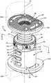
본 발명은 제1 및 제2 부재들 사이로 삽입되기 위한 팽창성 추간 임플란트에 관한 것이다. 임플란트는 제1 부재, 제2 부재, 및 제1 및 제2 부재에 작동 가능하게 연결된 칼라(collar)를 구비하고, 칼라는 칼라의 회전이 제1 부재에 대하여 제2 부재를 축방향으로 움직이게 하는 나사 메커니즘과 적어도 미리 결정된 양의 힘이 제1 부재와 제2 부재의 어느 하나 또는 모두에 가해질 때, 제2 부재가 제1 부재에 대해 라체트-타입 방식으로 축방향으로 움직이는 라체트 메커니즘을 포함할 수 있다. 제2 부재가 제1 부재 내부에 적어도 부분적으로 수납되도록 제2 부재는 제1 부재보다 약간 작을 수 있다.The present invention relates to an expandable intervertebral implant for insertion between first and second members. The implant includes a first member, a second member, and a collar operatively connected to the first and second members, wherein the collar is configured to allow the rotation of the collar to axially move the second member relative to the first member A screw mechanism and a ratchet mechanism in which the second member axially moves in a ratchet-type manner relative to the first member when at least a predetermined amount of force is applied to either or both of the first and second members can do. The second member may be slightly smaller than the first member so that the second member is at least partially contained within the first member.
다른 예시적인 실시예에 있어서, 추간 임플란트는 제1 끝단 및 제2 끝단을 가진 제1 본체 부재를 포함할 수 있고, 제1 끝단은 제1 척추골의 종판(endplate)의 적어도 일 부분과 결합할 수 있다. 임플란트는 또한 제1 끝단 및 제2 끝단을 가진 제2 본체 부재를 포함할 수 있고, 제1 끝단은 제2 척추골의 종판의 적어도 일 부분과 결합할 수 있다. 제2 본체 부재는 바람직하게 그 위에 형성된 적어도 하나의 나사 이빨 형태의 라체트를 포함한다. 드라이브 링(drive ring)은 바람직하게 제1 본체 부재에 회전 가능하게 부착되고, 바람직하게 제2 본체 부재를 수납하기 위한 내부 구멍을 포함한다. 라체트 링은 드라이브 링과 작동 가능하게 연결되고 바람직하게 제1 본체 부재에 형성된 나사 이빨 형태의 라체트와 결합하기 위해 그 위에 형성된 적어도 하나의 상응하는 나사 이빨 형태의 라체트를 가진 내부 구멍을 포함한다. 사용 시, 드라이브 링의 회전은 바람직하게 라체트 링의 회전을 유발하여 결국 바람직하게 제2 본체 부재가 제1 본체 부재에 대해 축방향으로 움직이게 한다. 라체트 링은 바람직하게 방사상으로 유연하므로 라체트 링에 형성된 나사 이빨 형태의 라체트는 제2 본체 부재에 형성된 나사 이빨 형태의 라체트와 분리되는 위치로 움직일 수 있으므로 제2 본체 부재는 제1 본체 부재에 대해 축방향으로 움직일 수 있다.In another exemplary embodiment, the intervertebral implant may comprise a first body member having a first end and a second end, the first end being capable of engaging with at least a portion of an endplate of the first vertebra have. The implant may also include a second body member having a first end and a second end, wherein the first end may engage at least a portion of the endplate of the second vertebra. The second body member preferably includes at least one screw-shaped ratchet formed thereon. The drive ring is preferably rotatably attached to the first body member and preferably includes an inner bore for receiving the second body member. The ratcheting ring includes an inner hole operatively connected to the drive ring and having at least one corresponding screw-shaped ratchet formed thereon for engaging with a ratchet in the form of a screw tooth, preferably formed in the first body member do. In use, rotation of the drive ring preferably causes rotation of the ratchet ring, eventually preferably causing the second body member to move axially relative to the first body member. The ratchet ring is preferably radially flexible so that the ratchet in the form of a screw tooth formed on the ratchet ring can move to a position separated from the ratchet in the form of a screw tooth formed on the second body member, Can be moved axially with respect to the member.
본 발명의 다른 측면에 있어서, 제1 및 제2 본체 부재들 사이에 위치된 추간판 공간 속으로 이식을 위한 높이 조절 가능한 추간 임플란트의 예시적인 사이징(sizing) 방법은: (i) 제1 본체 부재, 제2 본체 부재 및 제1 및 제2 본체 부재들과 작동 가능하게 연결된 칼라를 가진 임플란트를 제공하는 단계; (ii) 제1 및 제2 본체 부재들 사이의 공간에 가깝게 하기 위하여 축방향 라체트-타입 방식으로 제1 본체 부재에 대해 제2 본체 부재가 움직일 수 있도록 제1 및 제2 본체 부재들 중 적어도 어느 하나에 적어도 미리 결정된 양의 힘을 가하는 단계; 및 (iii) 제1 및 제2 본체 부재들 사이의 디스크 공간에 임플란트의 총 높이를 정교하게 조정하기 위해 제1 본체 부재에 대해 제2 본체 부재가 축방향으로 움직이도록 제2 본체 부재에 대해 칼라를 회전시키는 단계를 포함할 수 있다.In another aspect of the present invention, an exemplary sizing method of a height adjustable intervertebral implant for implantation into a disc space located between first and second body members comprises the steps of: (i) Providing an implant having a second body member and a collar operatively associated with the first and second body members; (ii) at least one of the first and second body members so that the second body member is movable relative to the first body member in an axial, rat-type manner to approximate the space between the first and second body members Applying at least a predetermined amount of force to either one; And (iii) a second body member for axially moving relative to the first body member to precisely adjust the total height of the implant in the disk space between the first and second body members. As shown in FIG.
전술한 요약 뿐만 아니라 본 발명의 바람직한 실시예들의 상세한 설명은 첨부된 도면들과 함께 읽혀질 때 더 잘 이해될 것이다. 본 출원의 조절 가능한 추간 임플란트의 설명의 목적으로, 바람직한 실시예들의 도면들이 도시된다. 그러나, 본 출원은 도시된 정밀한 장치들 및 도구들에 한정되는 것은 아니고 청구범위는 도시 된 실시예들에 한정되어서는 아니됨을 이해해야 한다.The foregoing summary, as well as a detailed description of preferred embodiments of the invention, will be better understood when read in conjunction with the appended drawings. For purposes of describing the adjustable intervertebral implant of the present application, the drawings of preferred embodiments are shown. It should be understood, however, that the present application is not limited to the precise devices and tools shown and that the scope of the claims is not limited to the embodiments shown.
도 1은 본 발명의 바람직한 제1 실시예에 따른 것으로서, 팽창된 위치에 배치된, 조절 가능한 추간 임플란트의 상부 사시도이다.1 is a top perspective view of an adjustable intervertebral implant according to a first preferred embodiment of the present invention and disposed in an inflated position;
도 2는 명확성을 위해 종판이 제거되고 붕괴된 위치에 배치된, 도 1에 도시된 추간 임플란트의 일 부분의 상부 사시도이다.Fig. 2 is a top perspective view of a portion of the intervertebral implant shown in Fig. 1 disposed in a collapsed position with the suture plate removed for clarity.
도 3a는 도 2의 3-3선을 따라 취한, 붕괴된 위치에 배치된, 도 1에 도시된 추간 임플란트의 일 부분의 단면도이다.FIG. 3A is a cross-sectional view of a portion of the intervertebral implant shown in FIG. 1, disposed in a collapsed position, taken along line 3-3 of FIG.
도 3b는 도 3a의 3A원 내부 도면으로서, 팽창된 위치에 배치된, 도 1에 도시된 추간 임플란트의 일 부분의 확대 단면도이다.FIG. 3B is an enlarged cross-sectional view of a portion of the intervertebral implant shown in FIG. 1, disposed in an expanded position, as a 3A inner view of FIG. 3A.
도 4는 도 1에 도시된 추간 임플란트의 제1 또는 외부 본체 부재의 상부 사시도이다.Figure 4 is a top perspective view of the first or outer body member of the intervertebral implant shown in Figure 1;
도 5는 도 1에 도시된 추간 임플란트의 제2 또는 내부 본체 부재의 상부 사시도이다.5 is a top perspective view of a second or inner body member of the intervertebral implant shown in Fig.
도 6은 도 5에 도시된 제2 또는 내부 본체 부재의 후방 입면도이다.6 is a rear elevational view of the second or inner body member shown in Fig.
도 7은 도 5의 7-7선을 따라 취한, 도 5에 도시된 제2 또는 내부 본체 부재의 단면도이다.7 is a cross-sectional view of the second or inner body member shown in Fig. 5, taken along line 7-7 of Fig.
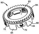
도 8a는 도 1에 도시된 추간 임플란트의 드라이브 링의 상부 사시도이다.8A is a top perspective view of the drive ring of the intervertebral implant shown in FIG.
도 8b는 도 8a에 도시된 드라이브 링의 바닥 사시도이다.8B is a bottom perspective view of the drive ring shown in FIG. 8A.
도 9는 도 8a에 도시된 드라이브 링의 측입면도이다.9 is a side elevational view of the drive ring shown in Fig.
도 10은 도 1에 도시된 추간 임플란트의 라체트 링의 상부 평면도이다.10 is a top plan view of the ratcheting of the intervertebral implant shown in Fig.
도 11은 도 10의 11-11선을 따라 취한, 도 10에 도시된 라체트 링의 단면도이다.11 is a cross-sectional view of the ratcheting shown in Fig. 10 taken along the line 11-11 in Fig.
도 12는 도 11의 12원 내부의 도면으로서, 도 10에 도시된 라체트 링의 확대 단면도이다.12 is an enlarged cross-sectional view of the ratcheting ring shown in Fig.
도 13은 도 1의 13-13선을 따라 취한, 도 1에 도시된 추간 임플란트의 단면도이다.Fig. 13 is a cross-sectional view of the intervertebral implant shown in Fig. 1, taken along line 13-13 of Fig.
도 14는 도 1에 도시된 추간 임플란트의 종판의 상부 평면도이다.14 is a top plan view of the end plate of the intervertebral implant shown in Fig.
도 15는 본 발명의 바람직한 제2 실시예에 따른 조절 가능한 추간 임플란트의 측입면도이다.15 is a side elevational view of an adjustable intervertebral implant according to a second preferred embodiment of the present invention.
특정의 용어는 이어지는 상세한 설명에서 편의성을 위해서만 사용되고 제한적인 것은 아니다. 용어, "우측", "좌측", "하부" 및 "상부"는 참조가 되는 도면들에서의 방향들을 나타낸다. 단어 "안쪽으로" 및 "바깥쪽으로"는 조절 가능한 추간 임플란트 및 그 지정된 부품들의 기하학적 중앙을 향하거나 그로부터 멀어지는 방향을 나타낸다. 단어 "전방", "후방", "상위", "하위", 및 관련된 단어들 및/또는 구절들은 참조가 되는 인체의 바람직한 위치들과 방위들을 나타내며 제한적으로 세겨져서는 안된다. 용어는 전술한 단어들, 그 파생어들 및 유사한 의미를 가진 단어들을 포함한다.Certain terminology is used for convenience only and is not limiting in the following detailed description. The terms "right "," left ", "lower" and "upper" The words " inside "and" outward " refer to the direction of the geometric center of the adjustable intervertebral implant and its designated components or away from it. The words "forward "," rearward ", "upper "," lower ", and related words and / or phrases refer to the preferred positions and orientations of the human body to which reference is made and should not be construed as limited. The term includes the words mentioned above, derivatives thereof, and words having similar meanings.
특정의 예시적 실시예들은 도면들을 참조하여 설명될 것이다. 일반적으로, 그러한 실시예들은 추간 임플란트에 관한 것으로서, 비-제한적인 예시에 의해, 제1 및 제2 인접한 즉, 이웃하는 척추골 중간의 환자의 척추 속으로 이식하기 위한 팽창성 추간 임플란트에 관한 것이다. 만약, 절개 장치(corpectomy device)로서 사용되면, 추간 임플란트는 단일 또는 멀티 레벨 수술 즉, 하나의 척추골 및/또는 척추골의 부분들의 하나 또는 그 이상의 제거를 수행할 수 있다. 임플란트는 척추골의 사이 또는 그 내부에 삽입될 수 있고, 예를 들어, 하나 또는 그 이상의 척추골의 부분들이 제거될 수 있고 임플란트는 척추골의 안쪽 부분과 접촉할 수 있다.Certain exemplary embodiments will be described with reference to the drawings. In general, such embodiments relate to an intervertebral implant, by non-limiting example, to an expandable intervertebral implant for implantation into a vertebra of a patient in a first and second adjacent, i. If used as a corpectomy device, the intervertebral implant may perform single or multi-level surgery, i.e., removal of one or more portions of one vertebra and / or vertebra. Implants may be inserted between or within the vertebrae, e.g., portions of one or more vertebrae may be removed, and the implant may contact the inner portion of the vertebra.
추간 임플란트는 본 명세서에 설명된 것들에 대한 대안적 적용 및 용도를 가질 수 있고, 설명되고 예시된 구조와 용도에 한정되어서는 아니된다. 즉, 추간 임플란트는 척추(예, 요추, 흉추, 경추 영역들)에 대체적으로 사용될 수 있는 것으로서 설명될 것이지만, 당업자들은 추간 임플란트가 신체의 다른 부분에도 사용될 수 있으며 의료 장치 분야 이외의 다른 적용 분야를 가질 수도 있음을 이해할 것이다.Intervertebral implants may have alternative applications and uses for those described herein, and should not be limited to the structures and applications described and illustrated. That is, an intervertebral implant will be described as being generally available for the spine (e.g., lumbar, thoracic, and cervical regions), but those skilled in the art will recognize that the intervertebral implant may be used in other parts of the body, As will be appreciated by those skilled in the art.
도 1 내지 도 3b 및 도 15를 참조하면, 바람직한 제1 및 제2 실시예들의 추간 임플란트(10)(210)는, 스테인리스 스틸, 티타늄, 티타늄 합금, 세라믹, 폴리테트라플루오로에틸렌("PTFE") 등을 포함하지만 이에 한정되지 않는 폴리머를 포함하지만 이에 한정되지 않는 업계에 알려진 그 어떤 생체적합성 물질 또는 그 조합에 의해 제조될 수 있다. 바람직하게, 추간 임플란트(10)(210)는 임플란트의 배치 및 위치가 식별되도록 방사선-비투과성일 수 있다.1 to 3B and 15, the intervertebral implant 10 (210) of the first and second preferred embodiments is made of stainless steel, titanium, titanium alloy, ceramic, polytetrafluoroethylene ("PTFE" ), And the like, including, but not limited to, polymers. Preferably, the intervertebral implant 10 (210) may be radiation-impermeable such that the placement and location of the implant is identified.
임플란트(10)(210)의 모든 구성요소들은 동일한 물질로 제조될 수 있거나, 바람직한 경우, 예를 들어, 내구성과 강도를 증대시키고 마찰과 마모를 감소시키기 위한 다른 물질들이 사용될 수 있다. 또한, 하나 또는 그 이상의 코팅이 하나 또는 그 이상의 구성요소들에 가해질 수 있다.All components of the implant 10 (210) may be made of the same material, or other materials may be used if desired, for example, to increase durability and strength and to reduce friction and wear. In addition, one or more coatings may be applied to one or more components.
도 1 내지 도 3을 참조하면, 바람직한 제1 실시예의 추간 임플란트(10)는 제1 본체 부재(20)와 제2 본체 부재(40)를 포함할 수 있다. 사용 시, 제2 본체 부재(40)는 바람직하게 제1 본체 부재(20) 보다 약간 작게 구성되므로 제2 본체 부재(40)는 제1 본체 부재(20) 안에 이동 가능하게 배치될 수 있다. 그 자체로, 제1 본체 부재(20)는 대체적으로 내부 본체 부재(20)로서 특징지워 질 수 있는 한편 제2 본체 부재(40)는 외부 본체 부재(40)로서 대체적으로 특징지워 질 수 있다. 그러나, 제1 본체 부재와 제2 본체 부재가 움직임 가능하게 연결되는 다른 정열들을 생각할 수 있음을 유의해야 한다. 예를 들어, 제1 및 제2 본체 부재들은 각각 끝단 부재 즉, 링으로부터 연장하는 복수의 레그들(legs)을 포함할 수 있고, 제1 부재의 레그는 제2 부재의 레그들에 대해 움직임 가능하게 이동될 수 있다.Referring to FIGS. 1 to 3, the
도 4에 가장 잘 도시된 바와 같이, 외부 본체 부재(20)는 바람직하게, 제1 끝단(22), 제2 끝단(24), 외면(26), 및 제1 끝단(22)으로부터 제2 끝단(24)까지 실질적으로 연장되는 내부 구멍(28)을 가진 실질적으로 속이 빈, 원통 부재이다. 외부 본체 부재(20)는 원통형에 한정되지 않고, 예를 들어, 정사각형, 사각형, 타원형, 계란형 또는 다른 모양과 같은 대안적인 모양일 수 있다. 외부 본체 부재(20)는 또한 그 외면(26)에 형성된 하나 또는 그 이상의 개구들(30)(31)을 포함할 수 있다. 바람직한 제1 실시예에 있어서, 외부 본체 부재(20)는 바람직하게 내부 구멍(28)으로의 접근을 허용하여 외과의사가 뼈 칩 또는 다른 이식편 물질을 대체로 이식된 구성으로 된 임플란트(10) 속으로 삽입할 수 있는 상대적으로 더 큰 뼈 팩 킹(bone packing) 개구(30)를 포함한다. 외부 본체 부재(20)는 또한 바람직하게 인접한 척추골(200)(202)의 융합을 촉진하기 위해 이식된 구성들에서 뼈의 내부 성장을 허용하는 여러 개의 보다 작은 내부-성장(in-growth) 개구들(31)을 포함한다. 추간 임플란트(31)는 뼈 팩킹 개구(30) 또는 내부-성장 개구들(31)의 포함하는 것에 한정되지 않고, 그 속의 개구들(30)(31)을 포함하지 않을 수도 있거나 임플란트(10)의 특정의 적용 또는 구성에 따라, 부가적인 가변성 모양의 개구들을 포함할 수도 있다.4, the
도 5 내지 도 7에 가장 잘 도시된 바와 같이, 내부 본체 부재(40)는 바람직하게 제1 끝단(42), 제2 끝단(44), 외면(46) 및 속이 빈 내부 공동(cavity)(48)을 가진 원통 부재의 형태일 수 있다. 도시된 바와 같이, 내부 본체 부재(40)의 외면(46)은 바람직하게 360도 각도로 둘레가 쳐지지 않으므로 내부 본체 부재(40)는 바람직하게 부분 원통 부재의 형태이다. 내부 본체 부재(40)는 부분적으로 원통-형태만을 형성하는 것에 한정되지 않고 완전한 원통 형태일 수도 있고 정사각형, 타원형 또는 외부 본체 부재(20)와 결합을 허용하는 그 어떤 다른 모양과 같은 대안적인 모양일 수 있다. 내부 본체 부재(40)는 정상적인 작동 상태를 지탱할 수 있고 아래에서 더 자세히 설명되겠지만 내부 본체 부재(40)의 바람직한 기능들을 수행할 수 있는 그 어떤 모양을 가질 수 있다.As best seen in Figures 5-7, the
도 1 내지 도 7을 참조하면, 바람직한 제1 실시예에 있어서, 내부 본체 부재(40)의 제1 끝단(42)은 상위 척추골(200)의 근처에 위치되고, 외부 본체 부재(20)의 제2 끝단은 이식된 상태에서 하위 척추골(202)의 근처에 위치된다. 내부 본체 부재(40)의 제1 끝단(42) 및 외부 본체 부재(20)의 제2 끝단(24)은 척추골(200)(202)과 면접촉할 필요는 없지만, 바람직하게 이식된 구성에서 척추골(200)(202)에 가깝게 위치된다. 예를 들어, 제1 끝단(42) 및 제2 끝단(24)은 이식된 구성에서 제1 끝단(42) 및 제2 끝단(24)에 각각 부착된 종판들(120)(122)(후술될 예정)에 의해 척추골(200)(202)로부터 이격될 수 있다.1 to 7, in a first preferred embodiment, the
도 2 및 도 3을 참조하면, 외부 본체 부재(20)의 제1 끝단(22)은 붕괴된 위치에서 제2 즉, 내부 본체 부재(40)의 제1 끝단(42) 근처에 위치된다. 또한, 붕괴된 위치에서, 외부 본체 부재(20)의 제2 끝단(24)은 내부 본체 부재(40)의 제2 끝단(44) 부근에 위치된다. 바람직한 제1 실시예의 임플란트(10)는 바람직하게 이러한 붕괴된 위치에서 가장 작은 높이를 가지며, 이러한 구성에서 환자 속으로 삽입 또는 이식되어 이식을 위해 요구되는 필요한 공간을 제한한다. 임플란트(10)가 팽창된 위치(도 1 내지 도 3b)로 내몰릴 때, 외부 본체 부재(20)의 제1 끝단(22)은 내부 본체 부재(40)의 제1 끝단(42)으로부터 멀어지게 움직인다. 팽창된 위치에서, 임플란트(10)는 붕괴된 위치에서의 임플란트의 높이보다 더 큰 높이를 가진다. 임플란트(20)는 인접한 척추골(200)(202) 또는 척추골(200)(202)의 부분들 사이의 다양한 간격들을 수용하기 위해 팽창된 위치에서 다양한 높이들을 취할 수 있다.2 and 3, the
도 1 내지 도 7을 참조하면, 외부 및 내부 본체 부재들(20)(40)은 바람직하게 공통의 세로축(12)을 따라 동축적으로 배치되고 바람직하게 서로에 대해 미끄러지게 배치(예, 끼워넣을 수 있게)되므로, 내부 본체 부재(40)의 축방향 위치는 외부 본체 부재(20)에 대해 조절될 수 있다. 외부 및 내부 본체 부재들(20)(40)은 서 로에 대해 끼워넣을 수 있는 배치 및/또는 미끄러지게 배치되는 것에 한정되지 않으며 외부 부재(20)의 제2 끝단에 대한 내부 부재(40)의 제1 끝단의 이동을 허용하기 위해 서로에 대하여 외부 및 내부 부재들(20)(40)의 상대 이동을 허용하는 그 어떤 방식으로 구성될 수 있다.Referring to Figures 1-7, the outer and
내부 본체 부재(40)의 외면(46)은 바람직하게 그 위에 형성된 나사 이빨 형태의 라체트(50)를 포함한다. 나사 이빨 형태의 라체트(50)는, 아래에서 더 상세히 설명되는 바와 같이, 내부 본체 부재(40)가 라체트 링(80)에 대해 회전될 때, 내부 본체 부재(40)가 라체트 링(80)에 대해 스크류-형태 부재로서 기능하고, 내부 본체 부재(40)와 외부 본체 부재(20) 사이의 축방향으로 충분한 축방향 힘이 가해질 때 내부 본체 부재(40)가 라체트 링(80)에 대해 움직이는 방식으로 이동을 허용하는 단면 모양을 포함하는 구조를 말한다. 축방향 이동은, 아래에서 더 상세히 설명되는 바와 같이, 내부 본체 부재(40) 및/또는 라체트 링(80) 중 적어도 어느 하나의 탄성 압축에 의해 용이해 질 수 있다. 나사 이빨 형태의 라체트는 축방향 이동과 회전 모두를 허용하는 한 어떠한 형태일 수 있다.The
나사 이빨 형태의 라체트(50)는, 내부 본체 부재(40)가 라체트 링(80)에 대해 또는 외부 본체 부재(20) 모두에 대해 회전할 수 있고, 내부 본체 부재(40)가 라체트 링(80)에 대해 또는 외부 본체 부재(20) 모두에 대해 추가적인 이동을 허용하는 예를 들어, 헬리컬 그루브, 돌기 또는 나사일 수 있다. 첨부된 도면들은 내부 본체 부재(40)가 단일의 연속된 길이의 나사 이빨 형태의 라체트(50)를 가지는 것으로서 도시하고 있지만, 임플란트(10)는 그것에 한정되는 것은 아니다. 예시적인 방식으로, 비나사 영역에 의해 분리된 나사 이빨 형태의 라체트의 불연속 부분들이 제공될 수 있고, 나사 이빨 형태의 라체트(50)는 또한 임플란트(10)의 세로축(12)에 평행하게 뻗어 있는 하나 또는 그 이상의 그루브들에 의해 가로막힐 수 있다.The
나사 이빨 형태의 라체트(50)의 피치, 모양 및 치수들은, 내부 본체 부재(40)가 바람직하게 회전 없이 외부 본체 부재(20)에 대해 움직일 때, 바람직하게 임플란트의 라체트 동작을 용이하게 하도록 선택될 수 있음을 이해해야 한다. 비-제한적인 예의 방식으로, "톱-이빨" 모양의 나사의 사용은 "일-방향" 라체트로 귀결되는 반면, 보다 더한 삼각형 모양의 나사의 사용은 당업자에 의해 이해될 수 있는 바와 같이, "2-방향" 라체트를 허용할 것이다. 라체트 형태의 동작을 수행할 때, 나사 이빨 형태의 라체트(50)는 바람직하게 축방향 이동을 허용하기 위해 라체트 링(80) 또는 외부 본체 부재(20)에 형성된 상응하는 나사 이빨 형태의 라체트(90) 위로 미끄러질 수 있다. 나사 이빨 형태의 라체트는 임플란트(10)가 라체트 형태의 운동을 겪을 때 라체트 링(80) 또는 외부 본체 부재(20)에 대해 방사상으로 움직일 수 있고, 나사 이빨 형태의 라체트의 방사상 이동은 라체트 이동을 용이하게 할 수 있다. 나사 이빨 형태의 라체트의 방사상의 운동은 나사 이빨 형태의 라체트 또는 나사 이빨 형태의 라체트가 고정되거나 형성된 부재의 탄성 유연성에 의해 제공될 수 있다. 대안적으로, 나사 이빨 형태의 라체트는 라체트 링(80)에 대해 방사상으로 움직이거나 방사상으로 회동하도록 스프링 바이어스될 수 있다. 도 3b에 가장 잘 도시된 바와 같이, 나사 이빨 형태의 라체트(50)는 하부 절단부(undercut) 또는 대략 7도 각도 정도의 음의 나사각을 가지므로, 임플란트(10)가 이식되면 결과적인 압축력은 내부 본체 부재(20)에 형성된 나사 이빨 형태의 라체트가 라체트 링(80)에 형성된 나사 이빨 형태의 라체트를 록킹시키게 하는 경향이 있다.The pitch, shape and dimensions of the
도 8a 내지 도 13을 참조하면, 추간 임플란트(10)는 또한 외부 및 내부 본체 부재들(20(40) 사이에 배치된 드라이브 링(60), 및 드라이브 링과 연결되고 바람직하게 드라이브 링(60) 내부에 내포된 라체트 링(80)을 포함할 수 있다. 비록 드라이브 링(60)과 라체트 링(80)은 대체로 두 개의 분리되고 독립된 구성요소들로 설명되겠지만, 드라이브 링(60)과 라체트 링(80)은 단일의 구성요소로서 일체로 형성될 수도 있고, 임플란트(10)의 동작 및/또는 바람직한 용도에 따라 다양한 구성요소들의 조립체로서 구성될 수도 있다. 드라이브 링(60)과 라체트 링(80)은 바람직하게 외부 및 내부 본체 부재들(20)(40)과 작용하여, 아래에서 더 상세히 설명되는 바와 같이, 스크류-형태의 조절 및 라체트-형태의 조절을 통해 임플란트(10)의 축방향 조작 또는 높이 변화를 허용한다.8A-13, the
도 8a 및 도 8b에 가장 잘 도시된 바와 같이, 드라이브 링(60)은 내부 본체 부재(40)가 조립된 구성으로 수납되는 내부 구멍(62)을 포함할 수 있다. 드라이브 링(60)은 또한 바람직하게 이동 가능하게 연결되고, 보다 바람직하게 외부 본체 부재(20)에 회전되게 부착된다. 드라이브 링(60)은 드라이브 링(60)을 외부 본체 부재(20)에 이동 가능하게 연결하고 바람직하게 회전 가능하게 부착시키는, 스냅 고정, 프레스 고정 등을 포함하지만 이에 한정되지 않는, 그 어떤 수단에 의해 외부 본체 부재(20)에 연결될 수 있다. 드라이브 링(60)은 바람직하게 외부 본체 부 재(20)에 형성된 원주 그루브(32)와 결합하기 위한 하나 또는 그 이상의 돌기들(64)을 포함한다. 바람직한 제1 실시예에 있어서, 드라이드 링(60)은 링(60)의 원주에 대하여 대체로 평평하게 방사상으로 위치된 다섯 개의 돌기들(64)을 포함한다. 외부 본체 부재(20)는 또한 바람직하게 구성요소들이 서로에 대해 축방향으로 움직일 때 외부 본체 부재(20)에 대해 내부 본체 부재(40)를 축방향으로 정렬하기 위해 내부 본체 부재(40)와 상호작용하는 정렬 돌기(23)를 포함한다.8A and 8B, the
드라이드 링(60)은 또한 그 표면에 형성된 링 기어(66)를 포함한다. 도시된 바와 같이, 링 기어(66)는 드라이드 링(60)의 외면(68)을 따라 형성될 수 있다. 링 기어(66)는 바람직하게 예를 들어, 피니언(미도시)과 같은 상응하는 도구와 협력하도록 구성될 수 있으므로, 수동 도구, 동력 도구 등에 연결될 수 있는 피니언의 회전은 드라이드 링(60)을 회전시키는 결과를 초래한다. 이러한 방식으로, 드라이브 링(60)은 링 기어(66) 및 피니언의 도움없이, 현재 알려지거나 앞으로 알려질 그 어떤 다른 수단에 의해 수동으로 회전될 수 있다.The
도 10 내지 도 13에 가장 잘 도시된 바와 같이, 라체트 링(80)은 제1 끝단(82), 제2 끝단(84), 외면(86), 제1 끝단(82)으로부터 제2 끝단(84)까지 확장하는 내부 구멍(88), 및 내부 본체 부재(40)의 외면(46)에 형성된 나사 이빨 형태의 라체트(50)와 결합하기 위해 내부 구멍(88)의 내면에 형성된 적어도 하나의 나사 메커니즘 또는 나사 이빨 형태의 라체트(90)를 포함한다. 라체트 링(80)은 바람직하게 드라이브 링(60) 내부에 포함되어 드라이드 링(60)에 연결되므로 드라이브 링(60)의 회전은 동시에 라체트 링(80)의 회전을 유발한다.As best seen in Figures 10-13, the ratcheting
또한, 라체트 링(80)은 유연할 수 있도록 라체트 링(80)은 적어도 하나의 슬롯(92)을 포함하므로, 예를 들어, 외부 및 내부 본체 부재들(20)(40)을 축방향으로 분리하도록 의도된 힘과 같이 적어도 미리 결정된 양의 축방향 힘에 라체트 링(80)이 종속될 때, 내부 본체 부재(40)가 라체트 링(80)에 대해 축방향으로 이동하는 것을 허용하기 위해 라체트 링(80)은 방사상으로 확장할 수 있다(아래에서 더욱 더 상세히 설명). 라체트 링은 그 어떤 다른 형태일 수 있으며, 예를 들어, 라체트 링은 연속적으로 확장 가능한 링인 것을 상정할 수 있으나, 링은 예를 들어, 그 재질 및/또는 구성에 의해 팽창될 수도 있다. 바람직하게, 라체트 링(80)은 탄력성이 있거나, 외부 본체 부재(40)에 대해 내부 본체 부재(20)의 축방향 위치를 대체적으로 확보하기 위해 라체트 링(80)의 내부 구멍(88)에 형성된 나사 이빨 형태의 라체트(90)가 내부 본체 부재(40)의 외면(46)에 형성된 나사 이빨 형태의 라체트(50)와 재-결합할 수 있도록 축방향 힘이 제거된 후 그 원래 크기 및/또는 형태로 대체로 회귀하도록 구성될 수 있다.It is also contemplated that the ratcheting
도 3b, 도 8b, 도 10 및 도 13을 참조하면, 바람직한 제1 실시예에서, 라체트 링(80)은 외부 본체 부재(20)의 제1 끝단(22), 내부 본체 부재(40)의 나사 이빨 형태의 라체트(50) 및 드라이브 링(60)의 내면에 의해 구획되는 공동(81)에 장착된다. 라체트 링(80)은 바람직하게 슬롯(92)에서 라체트 링(80)으로부터 방사상으로 외측으로 확장하고 드라이브 링(60)의 하방으로 종속하는 레그들(72) 사이에서 구획되는 라체트 정렬 갭(63)에 위치된 손잡이(91)를 포함한다. 바람직한 제1 실시예의 드라이브 링(60)은 다섯 개의 하방 종속 레그(72)를 포함하기 때문에 다섯 개의 정렬 갭(63)을 구획하므로 손잡이(91)는 조립된 구성에서 그 어떤 정렬 갭(63)에 위치될 수 있다. 라체트 링(80)은 공동(81)에 장착되어 있는 것에만 한정되지 않고 손잡이(91)는 정렬 갭(63)에 위치될 수 있고, 이빨 형태의 라체트(50)에 대해 라체트 링(80)의 상호 결합을 허용하는 그 어떤 기계적 구조들에 의해 드라이브 링(60) 및 임플란트에 연결될 수 있다.Referring to Figures 3B, 8B, 10 and 13, in a first preferred embodiment, the ratcheting
도 1 내지 도 13을 참조하면, 사용 시, 아래에서 더 상세히 설명되는 바와 같이, 외부 본체 부재(20), 드라이브 링(60) 및 라체트 링(80)은 바람직하게 서로에 대해 상대적인 축방향 위치에서 동일하게 유지되도록 구성되는 한편, 드라이브 링(60)과 라체트 링(80)은 모두 외부 본체 부재(20)에 대해 대체로 자유롭게 회전된다. 즉, 드라이브 링(60)과 라체트 링(80)은 바람직하게 대체로 축방향으로 고정되지만 외부 본체 부재(20)에 대해 회전되게 움직일 수 있도록 구성된다. 한편, 내부 본체 부재(40)는 바람직하게 사용자에 의한 임플란트(10)의 조작에 근거하여 외부 본체 부재(20), 드라이브 링(60) 및 라체트 링(80)에 대해 축방향으로 이동하도록 구성된다. 또한, 내부 본체 부재(40)는 바람직하게 축방향으로 움직이지만, 외부 본체 부재(20)에 대해 대체로 회전되지 않도록 구성된다. 이러한 방식으로, 당업자에 의해 일반적으로 평가되는 바와 같이, 드라이브 링(60)의 회전, 및 바람직하게 그에 연결된 라체트 링(80)의 회전은 내부 본체 부재(40)가 드라이브 링(60)과 라체트 링(80)에 대해, 그에 따라 외부 본체 부재(20)에 대해 축방향으로 움직이게 한다.Referring to Figures 1 to 13, in use, the
외부 본체 부재(20)에 대한 내부 본체 부재(40)의 관련 회전의 방지는 예를 들어 외부 본체 부재(20)의 내면에 하나 또는 그 이상의 가이드 슬롯(34:도 4)의 형성을 포함하지만 그에 한정되지 않는 현재 알려져 있거나 앞으로 알려질 그 어떤 다른 수단에 의해 수행될 수 있다. 가이드 슬롯(34)은 바람직하게 세로축(12)에 평행하게 연장하는 한편, 외부 본체 부재(20)에 대한 내부 본체 부재(40)의 회전을 방지 또는 대체로 제한하기 위해, 내부 본체 부재(40)는 외부 본체 부재(20)에 형성된 하나 또는 그 이상의 가이드 슬롯(34)과 협력하기 위한 하나 또는 그 이상의 핀 또는 리브(rib)(미도시)를 포함할 수 있다. 하나 또는 그 이상의 핀 또는 리브는 내부 본체 부재(40)와 일체로 형성될 수도 있고 분리된 구성요소로서 그에 부착될 수 있다. 대안적으로, 내부 본체 부재(40)는 하나 또는 그 이상의 가이드 슬롯을 포함할 수 있고 외부 본체 부재(20)는 하나 또는 그 이상의 핀 또는 리브를 포함할 수도 있다. 대안적으로, 내부 및 외부 본체 부재들(20)(40) 사이의 상대 회전을 방지 또는 대체로 제한하기 위해, 직사각형, 계란형, 타원형 등과 같은 상응하는 비-원형 모양을 포함하지만 그에 한정되지 않는, 다른 메커니즘이 사용될 수도 있다.The prevention of relative rotation of the
드라이브 링(60), 및 그에 연결된 라체트 링(80)의 회전은 바람직하게 추간 임플란트(10)에 형성된 나사 부품을 작동시킨다. 즉, 내부 및 외부 본체 부재들(40)(20)에 대해 회전하도록 된 드라이브 링(60)의 결과로서, 라체트 링(80)이 바람직하게 동시에 회전되어, 결과적으로, 내부 본체 부재(40)의 외면(46)에 형성된 나사 이빨 형태의 라체트(50) 및 라체트 링(80)의 내면에 형성된 나사 이빨 형태의 라체트(90)의 상호 작용의 결과로서, 내부 본체 부재(40)가 드라이브 링(60) 과 라체트 링(80)에 대해, 그래서 외부 본체 부재(20)에 대해 축방향으로 움직이게 된다. 도 13을 구체적으로 참조하면, 드라이브 링(60)이 초기에 회전될 때, 손잡이(91) 중 하나가 인접한 하방 종속 레그(72)를 가격할 때까지 라체트 링(80)은 회전하지 않는다. 손잡이들(91) 중 하나가 어느 하나의 하방 종속 레그(72)와 접촉하게 되면, 드라이브 링(60)과 라체트 링(80)은 손잡이(91)와 라체트 링(80)을 회전 방향으로 미는 하방 종속 레그(72) 때문에 함께 회전한다. 만약 사용자가 라체트 링(80)에 대해 드라이브 링(60)의 회전을 반대로 하면, 공동(63)의 반대면에 있는 반대편 하방 종속 레그(72)가 인접한 손잡이(91)를 가격하여, 라체트 링(80)이 하방 종속 레그(72)와 손잡이(91) 사이에서 접촉을 통해 회전을 강제할 때까지 라체트 링(80)은 드라이브 링(60)에 대해 회전하지 않을 것이다. 따라서, 초기 회전 동안, 어느 하나의 손잡이(91)가 어느 하나의 하방 종속 레그(72)와 접촉하게 될 때까지 드라이브 링(60)과 라체트 링(80) 사이의 상대적 회전은 약간의 "노는(play)" 상태일 수 있다. 바람직하게, 나사 메커니즘은 드라이브 링(60)이 어느 방향으로 회전하게 구동할 수 있으므로, 추간 임플란트(10)가 팽창 또는 수축될 수 있다. 따라서, 사용 시, 외부 및 내부 본체 부재들(20)(40)은 드라이브 링(60)과 라체트 링(80)의 회전을 통하여 팽창 및/또는 수축될 수 있다.Rotation of the
또한, 당업자에 의해 대체로 평가되는 바와 같이, 추간 임플란트(10)는 또한 바람직하게 사용자에게 예를 들어, 수동으로 또는 수술 도구의 도움으로 라체팅 부품을 통해 추간 임플란트(10)를 팽창 및/또는 수축시키기 위해 추간 임플란트(10)에 축방향 또는 분리 하중을 가할 능력을 제공한다. 즉, 외부 및 내부 본체 부재 들(20)(40)은 축방향 힘의 적용에 의해 라체트 타입 메커니즘을 통해 팽창 및/또는 수축될 수 있다. 예를 들어, 내부 본체 부재(40)에는 축 방향 힘을 외부 본체 부재(20)에는 동등한 반대 축방향 힘을 가하는 것과 같이, 추간 임플란트(10)에 충분한 축방향 분리력을 가하게 되면, 라체트 링(80)은 외측으로 굴곡 및/또는 편향되어 내부 본체 부재(40)의 외면(46)에 형성된 나사 이빨 형태의 라체트(50)가 상응하는 라체트 링(80)의 내면에 형성된 나사 이빨 형태의 라체트(90) 위로 및/또는 그것을 횡단하여 움직이게 하여 내부 본체 부재(40)는 드라이브 링(60)과 라체트 링(80)에 대해, 따라서 외부 본체 부재(20)에 대해 축방향으로 이동 또는 끼워넣어질 수 있다. 나사 이빨 형태의 라체트(50)(90)의 피크(peak)의 결합을 수용하기 위해 또는 라체트-타입 조절 동안 서로에 대해 피크들이 미끄러지는 것을 허용하기 위해 라체트 링(80)이 팽창하면, 손잡이들(91)이 인접한 하방 종속 레그(72)와 적어도 접촉할 때까지 손잡이들(91)은 공동(63) 안에서 팽창될 수 있다.Also, as generally appraised by those skilled in the art, the
바람직한 제1 실시예에 있어서, 임플란트(10)의 라체트 링(80)은 전술한 바와 같은 임플란트의 라체트-타입 조절을 수용하는 대부분의 만곡을 제공한다. 그러나, 임플란트는 그렇게 한정되지 않으며 라체트 링(80) 및/또는 내부 본체 부재(40)의 모두의 각각 또는 그 조합이 라체트 동작 중 굴곡될 수 있으므로, 내부 및 외부 본체 부재들(40)(20)이 라체트-타입 메커니즘을 이용하여 서로에 대해 축방향으로 움직일 때 나사 이빨 형태의 라체트들(90)(50)의 이빨이 서로들 위로 미끄러지고 다시 굴곡되어 결합하는 것을 허용한다.In a preferred first embodiment, the ratcheting 80 of the
따라서, 내부 및 외부 본체 부재들(40)(20)의 축방향 조절은, 사용자의 기호 에 따라 라체트-타입 조절 또는 스크류-타입 조절에 의해 얻어질 수 있다. 예를 들어, 내부 본체 부재(40)에 대한 외부 본체 부재(20)의 대략적인 공간은 라체트-타입 조절을 통해 수행될 수 있는 한편, 내부 본체 부재(40)에 대한 외부 본체 부재(20)의 축방향 옵셋의 정밀한 조절은 전술한 바와 같이 스크류-타입 조절을 통해 수행될 수 있다.Accordingly, the axial adjustment of the inner and
라체트 모드에서 추간 임플라트(10)의 사용은 대체로 보다 빠르고, 대체로 대략적인, 추간 임플란트(10)의 팽창/수축을 가능하게 한다. 또한, 라체트 모드에서 추간 임플란트(10)의 사용은 바람직하게 추간 임플란트(10)의 총 크기의 매크로 즉, 큰 사이즈 변화를 허용한다. 대조적으로, 나사 또는 스크류-타입 모드에서 임플란트(10)의 사용은 사용자에게 추간 임플란트(10)의 크기를 정교하게 상대적으로 정교한 방식으로 조절하도록 하는 능력을 제공한다. 또한, 드라이브 링(60)의 회전에 의한 팽창/수축은 보다 정밀할 수 있고, 따라서 사용자로 하여금 임플란트(10)의 총 높이를 정교하게 조정할 수 있게 한다. 임플란트(10)는 바람직하게 사용자가 사용자의 편의에 따라 언제라도 라체트-타입 조절 모드와 스크류-타입 조절 모드 사이에서 전환을 가능하게 한다.The use of the
내부 본체 부재(40)에 형성된 나사 이빨 형태의 라체트(50) 및 라체트 링(80)의 내면에 형성된 상응하는 나사 이빨 형태의 라체트(90)는 자체-잠금(self-lockig)이 되도록 구성되므로 내부 본체 부재(40)의 위치는 그 어떤 추가적인 잠금 메커니즘의 도움없이 외부 본체 부재(20)에 대해 고정될 수 있다. 대안적으로, 추간 임플란트(10)는 또한 라체트-타입 또는 스크류-타입 조절을 사용하여 사용자에 의해 바람직한 임플란트 높이가 얻어지면 내부 본체 부재(40)에 대한 외부 본체 부재(20)의 위치를 고정하기 위한 잠금 메커니즘을 포함할 수 있다. 예를 들어, 도 1 내지 도 3a에 가장 잘 도시된 바와 같이, 드라이브 링(60)은 하나 또는 그 이상의 세트 스크류(100)를 나사 결합에 의해 수용하기 위해 하방 종속 레그(72)에 형성된 하나 또는 그 이상의 나사 구멍(70)을 포함할 수 있다. 라체트 링(80)에 대해 드라이브 링(60)을 고정하고, 외부 본체 부재(20)에 대해 내부 본체 부재(40)를 대체적으로 고정하기 위해, 세트 스크류(100)의 끝이 접촉하여 라체트 링(80)의 외면(86)을 내부 본체 부재(40) 쪽으로 밀어서, 라체트 링(80)의 나사 이빨 형태의 라체트(90)가 내부 본체 부재(40)의 나사 이빨 형태의 라체트(90)에 접촉하도록 밀어제침에 의해 드라이브 링(60)에 대한 라체트 링(80)의 이동을 대체로 고정할 때까지 하나 또는 그 이상의 세트 스크류(100)는 어느 하나의 나사 구멍(70) 속으로 박히게 된다. 그러한 결합은, 나사 이빨 형태의 라체트들(90)(50) 때문에, 대체적으로 사용자가 드라이브 링(60)과 라체트 링(80)을 회전시키는 것을 방지한다. 또한, 나사 구멍(70)에 있는 세트 스크류들(100)의 회전 결합은 대체로 라체트 링(80)이 팽창하는 능력을 제한하여, 대체로 내부 본체 부재(40)가 라체트-타입 조절을 통해 외부 본체 부재(20)에 대해 움직이는 것을 방지한다.The
하나 또는 그 이상의 세트 스크류(100)는 내부 본체 부재(40)에 대해 외부 본체 부재(20)를 대체로 록킹하기 위해 조립된 구성에서 나사 구멍(70) 속으로 단단하게 조여지지만, 바람직한 실시예에서, 외과의사는 전형적으로 척추골(200)(202) 사이의 이식된 위치에 임플란트(10)를 정렬하고 난 후 외과의사를 면 하는 세트 스크류(100)의 어느 하나만을 조이게 된다. 대안적으로, 다른 록킹 메커니즘이 사용될 수 있는데, 예를 들어, 세트 스크류(100)는 내부 또는 외부 본체 부재들(40)(20)에 접촉될 수 있고, 결과적으로 대체로 드라이브 링(60)과 라체트 링(80)이 회전되는 것을 방지하고 내부 및 외부 본체 부재들(40)(20)이 서로에 대해 축방향으로 움직이는 것을 방지하거나, 외부 클램핑, 파스닝, 접촉 결합 또는 관련 메커니즘 및 방법들과 같이, 서로에 대하여 외부 및 내부 본체 부재들(20)(40)의 이동을 제한하는 그 어떤 다른 록킹 메커니즘이 사용될 수 있다.The one or
도 1 및 도 14에 가장 잘 도시된 바와 같이, 외부 및 내부 본체 부재들(20)(40)은, 인접한 척추골의 종판의 적어도 일 부분과 접촉하기 위해, 그곳에 각각 장착된 종판(120)(122)을 포함할 수 있다. 종판들(120)122)은 분리되고 뚜렷한 부품으로서 형성될 수도 있고, 간섭-고정, 프레스-고정, 나사 결합, 스크류 결합, 본딩, 세트 스크류 등을 포함하지만 이에 한정되지 않는 업계에 알려진 그 어떤 수단에 의해 외부 및 내부 본체 부재들(20)(40)에 연결될 수도 있다. 이러한 방식으로, 추간 임플란트(10)는 복수의 다른 종판들(120)(122)을 가진 키트로 제공될 수 있으므로 사용자는 환자의 척추골 종판의 윤곽에 가장 적합한 필요한 종판들(120)(122)을 선택할 수 있다. 예시적인 방식으로, 다양한 종판들(120)(122)이 제공될 수 있으며 원형, 정사각형, 직사각형, 계란형, 콩팥형 등을 포함하지만 이에 한정되지 않는 다양한 모양들 및/또는 대체로 웨지-모양의 표면, 편평한 표면 등과 같은 하나 또는 그 이상의 특징들을 포함한다. 바람직한 제1 실시예에 있어서, 종판들(120)(122)은 초기에 외부 및 내부 본체 부재들(20)(40)의 끝단(42)(24) 각각에서 팔각형 돌기(41)(25)와 결합하고, 외부 및 내부 본체 부재들(20)(40)의 내부 사사산(121)(123)과 결합하는 록킹 스크류(미도시)를 이용하여 외부 및 내부 본체 부재들(20)(40)에 고정된다. 대안적으로, 돌기(41)(25)는 외부 나사산을 가질 수 있으며 종판은 돌기 위에 고정되는 구멍 또는 공동 및 외부 및 내부 본체 부재들(20)(40)에 대한 종판들의 위치를 고정하기 위해 돌기에 형성된 나사산과 결합하기 위한 내부 나사산을 가진 세트 스크류를 가질 수 있다. 팔각형 돌기들(41)(25)은 외부 및 내부 본체 부재들(40)(20)에 대한 종판(120)(122)의 적어도 8개 방위를 허용한다. 팔각 돌기가 도시되고 설명되었지만, 원형, 타원형, 정사각형 또는 다른 모양들이 사용될 수 있음을 유의해야 한다.As best seen in Figures 1 and 14, the outer and
종판들(120)(122)은 바람직하게 인접한 척추골(200)(202)의 종판들과 접촉 및/또는 결합하기 위한 하나 또는 그 이상의 고정 부재들(124)을 포함한다. 고정 부재들(124)은 복수의 돌기들, 복수의 물결 구조, 복수의 돌출, 복수의 리지, 복수의 이빨, 하나 또는 그 이상의 용골(keel) 등을 포함하지만 이에 한정되지 않는 그 어떤 알려진 형태일 수 있다. 종판들(120)(122)은 또한 환자의 척추골에 종판들(120)(122)을 고정하기 위해, 예를 들어, 스크류, 핀 등과 같은 하나 또는 그 이상의 뼈 고정 요소들을 수납하도록 구성될 수 있다.
전술한 바와 같이, 외부 본체 부재(20)는 하나 또는 그 이상의 개구들(30)(31)을 포함할 수 있다. 내부 본체 부재(40)는 부분 원통 표면의 형태(예, 내부 본체 부재(40)의 벽들은 바람직하게 360도 각도로 원주가 형성되지 않음)일 수 있으므로 뼈 팩킹 개구(30) 및 내부 본체 부재(40)에 있는 부분 개구를 포함하 는 윈도우(125)는 뼈 칩 또는 다른 유사한 물질을 내부 본체 부재(40)의 공동(48) 속으로 전달하기 위해 추간 임플란트(10)에 형성된다. 또한, 외부 및 내부 본체 부재들(20)(40) 및 종판들(120)(122)은 바람직하게 척추골(200)(202)과 결합하는 부근의 끝단에서 개방되므로 뼈 칩 또는 다른 물질은 척추골(200)(202)과 면결합하거나 임플란트(10)의 구멍들을 통해 척추골(200)(202)과 물리적으로 연통한다.As described above, the
바람직한 제1 실시예에 있어서, 드라이브 링(60)과 라체트 링(80)은 외부 본체 부재(20)에 회전되게 장착된 칼라를 구비한다. 라체트 링(80)은 내부 본체 부재(40)의 외면에 있는 나사 이빨 형태의 라체트(50)와 결합하는 나사 이빨 형태의 라체트(90)를 포함한다. 라체트 링(80)의 나사 이빨 형태의 라체트(90)와 내부 본체 부재(40)의 나사 이빨 형태의 라체트(50)의 결합은 스크류-타입 방식 또는 조절에 있어서 외부 및 내부 본체 부재들(20)(40)에 대해 칼라를 회전시킴에 의해 외부 본체 부재(20)에 대한 내부 본체 부재(40)의 축방향 운동을 허용한다. 바람직한 제1 실시예에 있어서, 칼라는 또한 라체트 링(80)과 내부 본체 부재(40)의 상호 작용을 포함하는 라체트 메커니즘을 구비한다. 구체적으로, 외부 및 내부 본체 부재들(20)(40) 사이에 가해지는 미리 결정된 축방향 힘의 적용을 통해 나사 이빨 형태의 라체트(90)의 피크들이 내부 본체 부재(40)의 나사 이빨 형태의 라체트(50)를 통과하여 축방향으로 움직일 수 있도록 라체트 링(80)이 방사상으로 팽창하는 능력은 내부 및 외부 본체 부재들(20)(40)이 서로에 대해 축방향 라체트-타입 방식으로 움직이는 것을 허용한다.In the first preferred embodiment, the
도 15를 참조하면, 본 출원의 바람직한 제2 실시예에 있어서, 추간 임플란 트(210)는 바람직한 제1 실시예의 임플란트(10)와 실질적으로 유사하고 동일한 구성요소들 및 특징들은 대체로 본 실시예에서는 설명되지 않을 것이다. 추간 임플란트(210)는 외부 본체 부재(220), 내부 본체 부재(240), 및 캔틸레버 스프링 기어(260)를 구비할 수 있다. 대안적으로, 외부 본체 부재(220)는 캔틸레버 스프링 기어(260)와 일체로 형성될 수 있음을 상정할 수 있다. 바람직한 제1 실시예의 임플란트(10)의 내부 본체 부재(40)와 유사하게, 내부 본체 부재(240)는 바람직하게 그 외면에 형성된 나사 이빨 형태의 라체트(250)를 포함한다.Referring to Fig. 15, in a second preferred embodiment of the present application, the
외부 본체 부재(220) 및 캔틸레버 스프링 기어(260)는 바람직하게 그들의 상대적 축방향 위치를 유지하지만 캔틸레버 스프링 기어(260)가 외부 본체 부재(220)에 대해 바람직하게 그 축에 대해 회전하게 하는 방식으로 구성된다. 캔틸레버 스프링 기어(260)는 바람직하게 내면에 형성되고, 내부 본체 부재(240)의 외면에 형성된 나사 이빨 형태의 라체트(250)와 실질적으로 상응하는 짝을 이루도록 구성됨으로써 캔틸레버 스프링 기어(260)의 회전이 내부 본체 부재(240)가 캔틸레버 스프링 기어(260)에 대해 결과적으로 외부 본체 부재(220)에 대해 축방향으로 움직이게 하는, 나사 이빨 형태의 라체트(미도시)를 포함한다. 나사 이빨 형태의 라체트는 캔틸레버 스프링 기어(260)의 끝(262)에 형성된 턱 또는 돌기 형태일 수 있다.The
사용 시, 외부 본체 부재(220)에 대한 캔틸레버 스프링 기어(260)의 회전은 추간 임플란트(210)에 형성된 나사산 부품을 작동시켜 결과적으로 내부 본체 부재(240)가 캔틸레버 스프링 기어(260)에 대해, 결과적으로 외부 본체 부재(220)에 대해 축방향으로 이동하게 한다. 즉, 추간 임플란트(210)는 캔틸레버 스프링 기 어(260)를 회전시킴에 의해 내부 본체 부재(240)의 외면에 형성된 나사 이빨 형태의 라체트(250)를 사용하여 팽창 또는 수축될 수 있다. 캔틸레버 스프링 기어(260)가 회전할 때, 캔틸레버 스프링의 끝단은 내부 본체 부재(240)에 형성된 나사 이빨 형태의 라체트(250)와 결합하여 나사산을 따라 임플란트(210)가 팽창 또는 수축되게 한다.The rotation of the
또한, 당업자에 의해 대체로 평가될 바와 같이, 추간 임플란트(210)는 또한 바람직하게 사용자에게 라체트 부품을 통해 추간 임플란트(210)를 팽창 및/또는 수축시키기 위해 추간 임플란트(210)에 축방향 분리력을 가할 능력을 제공한다. 즉, 외부 및 내부 본체 부재들(220)(240)은 축방향 힘의 적용에 의한 라체트 타입 메커니즘을 통해 팽창 및/또는 수축될 수 있다. 추간 임플란트(210)에 충분한 축방향 힘을 가하게 되면, 내부 본체 부재(240)는 캔틸레버 스프링 기어(260)가 내부 본체 부재(240)의 외면에 형성된 나사 이빨 형태의 라체트(250)에 대해 그리고 그 위로 움직일 때 축방향으로 이동하여 외측으로 편향되어 내부 본체 부재(240)의 나사 이빨 형태의 라체트(250)가 축방향으로 통과하기 위한 공간을 제공할 것이다. 캔틸레버 스프링 기어(260)는 바람직하게 일단 축방향 힘이 제거되면 그 원래 위치로 회귀하도록 구성되므로 캔틸레버 스프링 기어(260)는 다른 위치에서 내부 본체 부재(240)의 외면에 형성된 나사 이빨 형태의 라체트(250)와 재-결합한다.As will also be appreciated by those skilled in the art, the
전술한 상세한 설명과 도면들은 본 발명의 바람직한 실시예들을 나타내며, 첨부된 청구범위에서 정의된 본 발명의 정신 및 범위를 벗어나지 않고 다양한 부가 물, 변형물, 조합물 및/대체물들이 가능함이 이해될 것이다. 특히, 본 발명은 발명의 정신 또는 근본 특징들을 벗어나지 않는 범위내에서 다른 특정의 형태들, 구조들, 배열들, 비례들, 및 다른 구성요소들, 물질들, 및 성분들이 구현될 수 있음은 당업자에게 명백할 것이다. 당업자는 본 발명이 본 발명의 원칙을 벗어나지 않는 범위 내에서 특정의 환경 및 작동 요구조건에 특히 적용될 수 있는 구조, 배열, 비례, 물질, 성분들의 많은 변화와 함께 사용될 수 있음을 알 것이다. 또한, 본 명세서에서 설명된 특징들은 독립적으로 또는 다른 특징들과 조합하여 사용될 수 있다. 현재 개시된 실시예들은 따라서, 모든 면에 있어서 예시적이지 제한적이서는 아니되며, 발명의 범위는 첨부된 특허청구범위에 의해 나타내져야 하며, 전술한 설명에 한정되어서는 아니된다.It is to be understood that the foregoing detailed description and drawings depict preferred embodiments of the invention and that various additions, modifications, combinations and alternatives are possible without departing from the spirit and scope of the invention as defined in the appended claims . In particular, it will be understood by those skilled in the art that other specific forms, structures, arrangements, proportions, and other elements, materials, and components may be implemented without departing from the spirit or essential characteristics of the invention. . Those skilled in the art will appreciate that the present invention can be used with many changes in structure, arrangement, proportions, materials, components, and the like, which are particularly applicable to specific environments and operating requirements, without departing from the principles of the invention. In addition, the features described herein may be used independently or in combination with other features. The presently disclosed embodiments are therefore to be considered in all respects as illustrative and not restrictive, the scope of the invention being indicated by the appended claims, and not limited to the foregoing description.
Claims (20)
Translated fromKoreanApplications Claiming Priority (3)
| Application Number | Priority Date | Filing Date | Title |
|---|---|---|---|
| US89456807P | 2007-03-13 | 2007-03-13 | |
| US60/894,568 | 2007-03-13 | ||
| PCT/US2008/056898WO2008112923A1 (en) | 2007-03-13 | 2008-03-13 | Adjustable intervertebral implant |
Publications (2)
| Publication Number | Publication Date |
|---|---|
| KR20090121278A KR20090121278A (en) | 2009-11-25 |
| KR101453961B1true KR101453961B1 (en) | 2014-10-21 |
Family
ID=39591432
Family Applications (1)
| Application Number | Title | Priority Date | Filing Date |
|---|---|---|---|
| KR1020097015899AExpired - Fee RelatedKR101453961B1 (en) | 2007-03-13 | 2008-03-13 | adjustable intervertebral implant |
Country Status (11)
| Country | Link |
|---|---|
| US (1) | US8992617B2 (en) |
| EP (1) | EP2155117B1 (en) |
| JP (1) | JP2010521242A (en) |
| KR (1) | KR101453961B1 (en) |
| CN (1) | CN101631516A (en) |
| AU (1) | AU2008224951A1 (en) |
| BR (1) | BRPI0808817A2 (en) |
| CA (1) | CA2676616C (en) |
| CO (1) | CO6210800A2 (en) |
| WO (1) | WO2008112923A1 (en) |
| ZA (1) | ZA200905203B (en) |
Families Citing this family (94)
| Publication number | Priority date | Publication date | Assignee | Title |
|---|---|---|---|---|
| US20060058798A1 (en)* | 2004-08-24 | 2006-03-16 | Roman Shawn D | Bone distractor with ratchet mechanism |
| WO2008070863A2 (en) | 2006-12-07 | 2008-06-12 | Interventional Spine, Inc. | Intervertebral implant |
| US8900307B2 (en) | 2007-06-26 | 2014-12-02 | DePuy Synthes Products, LLC | Highly lordosed fusion cage |
| TWI383772B (en)* | 2007-11-30 | 2013-02-01 | 趙振綱 | Adjustable artificial vertebral body stent |
| EP2237748B1 (en) | 2008-01-17 | 2012-09-05 | Synthes GmbH | An expandable intervertebral implant |
| US8992620B2 (en) | 2008-12-10 | 2015-03-31 | Coalign Innovations, Inc. | Adjustable distraction cage with linked locking mechanisms |
| US20100145455A1 (en) | 2008-12-10 | 2010-06-10 | Innvotec Surgical, Inc. | Lockable spinal implant |
| US8696751B2 (en)* | 2008-12-10 | 2014-04-15 | Coalign Innovations, Inc. | Adjustable distraction cage with linked locking mechanisms |
| US12232975B2 (en) | 2008-02-22 | 2025-02-25 | Howmedica Osteonics Corp. | Lockable spinal implant |
| US8936641B2 (en) | 2008-04-05 | 2015-01-20 | DePuy Synthes Products, LLC | Expandable intervertebral implant |
| BRPI0822953A2 (en) | 2008-09-04 | 2015-06-23 | Synthes Gmbh | Adjustable intervertebral implant |
| JP2012502702A (en)* | 2008-09-19 | 2012-02-02 | ウルリッヒ ゲーエムベーハー ウント コンパニ カーゲー | Implants for insertion between vertebral bodies of the spine |
| US8721723B2 (en) | 2009-01-12 | 2014-05-13 | Globus Medical, Inc. | Expandable vertebral prosthesis |
| US9387090B2 (en) | 2009-03-12 | 2016-07-12 | Nuvasive, Inc. | Vertebral body replacement |
| US9687357B2 (en) | 2009-03-12 | 2017-06-27 | Nuvasive, Inc. | Vertebral body replacement |
| US9526620B2 (en) | 2009-03-30 | 2016-12-27 | DePuy Synthes Products, Inc. | Zero profile spinal fusion cage |
| US8211178B2 (en)* | 2009-06-18 | 2012-07-03 | Warsaw Orthopedic | Intervertebral implant with a pivoting end cap |
| US8062375B2 (en)* | 2009-10-15 | 2011-11-22 | Globus Medical, Inc. | Expandable fusion device and method of installation thereof |
| US20110106258A1 (en)* | 2009-10-30 | 2011-05-05 | Warsaw Orthopedic, Inc. | End cap for a vertebral implant |
| US9393129B2 (en) | 2009-12-10 | 2016-07-19 | DePuy Synthes Products, Inc. | Bellows-like expandable interbody fusion cage |
| DE102010004275A1 (en)* | 2010-01-11 | 2011-07-21 | Metz-Stavenhagen, Peter, Dr. med., 34537 | Vertebral body spacer |
| US8353963B2 (en)* | 2010-01-12 | 2013-01-15 | Globus Medical | Expandable spacer and method for use thereof |
| KR101010306B1 (en)* | 2010-02-01 | 2011-01-25 | 장웅규 | Spinal Body Replacement |
| PL217567B1 (en)* | 2010-03-03 | 2014-07-31 | Lfc Spółka Z Ograniczoną Odpowiedzialnością | Prosthesis of anterior spinal column, prosthesis guiding tool and method for the implantation thereof |
| BR112012020550A2 (en)* | 2010-03-04 | 2017-06-27 | Synthes Gmbh | expandable laminar implant for spinal fusion. |
| US8870880B2 (en) | 2010-04-12 | 2014-10-28 | Globus Medical, Inc. | Angling inserter tool for expandable vertebral implant |
| US8591585B2 (en)* | 2010-04-12 | 2013-11-26 | Globus Medical, Inc. | Expandable vertebral implant |
| US9579211B2 (en)* | 2010-04-12 | 2017-02-28 | Globus Medical, Inc. | Expandable vertebral implant |
| US8282683B2 (en)* | 2010-04-12 | 2012-10-09 | Globus Medical, Inc. | Expandable vertebral implant |
| US11426287B2 (en)* | 2010-04-12 | 2022-08-30 | Globus Medical Inc. | Expandable vertebral implant |
| US9301850B2 (en)* | 2010-04-12 | 2016-04-05 | Globus Medical, Inc. | Expandable vertebral implant |
| US8979860B2 (en) | 2010-06-24 | 2015-03-17 | DePuy Synthes Products. LLC | Enhanced cage insertion device |
| US9907560B2 (en) | 2010-06-24 | 2018-03-06 | DePuy Synthes Products, Inc. | Flexible vertebral body shavers |
| US8623091B2 (en) | 2010-06-29 | 2014-01-07 | DePuy Synthes Products, LLC | Distractible intervertebral implant |
| US20120029640A1 (en)* | 2010-07-29 | 2012-02-02 | Warsaw Orthopedic, Inc. | Vertebral implant end cap |
| WO2012022047A1 (en)* | 2010-08-20 | 2012-02-23 | Tongji University | Rod system for gradual dynamic spinal fixation |
| US20120078372A1 (en) | 2010-09-23 | 2012-03-29 | Thomas Gamache | Novel implant inserter having a laterally-extending dovetail engagement feature |
| US9402732B2 (en) | 2010-10-11 | 2016-08-02 | DePuy Synthes Products, Inc. | Expandable interspinous process spacer implant |
| US9572678B2 (en)* | 2012-02-07 | 2017-02-21 | Medivest, Llc | Tissue spacer implants, insertion and adjustment tools, and method of use |
| US9138324B2 (en)* | 2013-01-24 | 2015-09-22 | Warsaw Orthopedic, Inc. | Expandable spinal implant system and method |
| US9717601B2 (en) | 2013-02-28 | 2017-08-01 | DePuy Synthes Products, Inc. | Expandable intervertebral implant, system, kit and method |
| US9522070B2 (en) | 2013-03-07 | 2016-12-20 | Interventional Spine, Inc. | Intervertebral implant |
| RU2520799C1 (en)* | 2013-03-19 | 2014-06-27 | Общество с ограниченной ответственностью "ОРФО" | Telescopic vertebral prosthesis and method for implantation thereof |
| AU2014268740B2 (en)* | 2013-05-20 | 2018-04-26 | K2M, Inc. | Adjustable implant and insertion tool |
| US9283090B2 (en)* | 2013-07-19 | 2016-03-15 | Warsaw Orthopedic, Inc. | Spinal construct and method |
| US9427325B2 (en) | 2013-07-26 | 2016-08-30 | Warsaw Orthopedic, Inc. | Interbody implant and method |
| US9566167B2 (en) | 2013-08-22 | 2017-02-14 | K2M, Inc. | Expandable spinal implant |
| CN103431902B (en)* | 2013-08-30 | 2015-05-06 | 常州鼎健医疗器械有限公司 | Vertebral body fusion device |
| US9585762B2 (en) | 2014-10-09 | 2017-03-07 | K2M, Inc. | Expandable spinal interbody spacer and method of use |
| WO2016077606A1 (en) | 2014-11-12 | 2016-05-19 | Medivest, Llc | Spinal spacing implant, spinal spacer assembly, expander and insertion instrument, kit and methods of assembly and use |
| US10363142B2 (en) | 2014-12-11 | 2019-07-30 | K2M, Inc. | Expandable spinal implants |
| CN104546228A (en)* | 2015-01-07 | 2015-04-29 | 北京爱康宜诚医疗器材股份有限公司 | Adjustable self-stabilizing type artificial sacrum prosthesis |
| US11426290B2 (en) | 2015-03-06 | 2022-08-30 | DePuy Synthes Products, Inc. | Expandable intervertebral implant, system, kit and method |
| US9775719B2 (en) | 2015-03-23 | 2017-10-03 | Musc Foundation For Research Development | Expandable vertebral body replacement device and method |
| US9889018B2 (en) | 2015-03-23 | 2018-02-13 | Musc Foundation For Research Development | Expandable vertebral body replacement device and method |
| US9913727B2 (en)* | 2015-07-02 | 2018-03-13 | Medos International Sarl | Expandable implant |
| US10004608B2 (en) | 2016-02-26 | 2018-06-26 | K2M, Inc. | Insertion instrument for expandable spinal implants |
| US10548738B2 (en) | 2016-04-07 | 2020-02-04 | Howmedica Osteonics Corp. | Expandable interbody implant |
| US9844446B2 (en)* | 2016-05-05 | 2017-12-19 | Globus Medical, Inc. | Expandable vertebral implant |
| AU2017203369B2 (en) | 2016-05-20 | 2022-04-28 | Vb Spine Us Opco Llc | Expandable interbody implant with lordosis correction |
| US11510788B2 (en) | 2016-06-28 | 2022-11-29 | Eit Emerging Implant Technologies Gmbh | Expandable, angularly adjustable intervertebral cages |
| EP3474784A2 (en) | 2016-06-28 | 2019-05-01 | Eit Emerging Implant Technologies GmbH | Expandable and angularly adjustable intervertebral cages with articulating joint |
| LU93170B1 (en)* | 2016-08-11 | 2018-03-28 | Ulrich Gmbh & Co Kg | Attachment of tracking elements to surgical instruments |
| AU2017228529B2 (en) | 2016-09-12 | 2022-03-10 | Vb Spine Us Opco Llc | Interbody implant with independent control of expansion at multiple locations |
| US11596526B2 (en)* | 2016-09-14 | 2023-03-07 | Globus Medical Inc. | Systems and methods for expandable corpectomy spacer implantation |
| US20240390158A1 (en)* | 2016-09-14 | 2024-11-28 | Globus Medical, Inc. | Systems and methods for expandable corpectomy spacer implantation |
| US12161563B2 (en)* | 2016-09-14 | 2024-12-10 | Globus Medical, Inc. | Systems and methods for expandable corpectomy spacer implantation |
| EP4501265A3 (en) | 2016-10-14 | 2025-04-30 | Intuitive Surgical Operations, Inc. | Systems for applying preload to surgical instruments and related procedures |
| AU2017251734B2 (en) | 2016-10-26 | 2022-10-20 | Vb Spine Us Opco Llc | Expandable interbody implant with lateral articulation |
| US10537436B2 (en) | 2016-11-01 | 2020-01-21 | DePuy Synthes Products, Inc. | Curved expandable cage |
| CN106510905A (en)* | 2016-11-23 | 2017-03-22 | 大博医疗科技股份有限公司 | Stable and adjustable artificial vertebral body |
| JP2020500677A (en) | 2016-11-28 | 2020-01-16 | エムユーエスシー ファウンデーション フォー リサーチ ディベロップメントMusc Foundation For Research Development | Telescopic vertebral body replacement device and method |
| US10888433B2 (en) | 2016-12-14 | 2021-01-12 | DePuy Synthes Products, Inc. | Intervertebral implant inserter and related methods |
| CN106890037A (en)* | 2017-04-10 | 2017-06-27 | 北京大学人民医院 | One kind can extend artificial vertebral body in vivo |
| US10398563B2 (en) | 2017-05-08 | 2019-09-03 | Medos International Sarl | Expandable cage |
| US11344424B2 (en) | 2017-06-14 | 2022-05-31 | Medos International Sarl | Expandable intervertebral implant and related methods |
| US10940016B2 (en) | 2017-07-05 | 2021-03-09 | Medos International Sarl | Expandable intervertebral fusion cage |
| US10441430B2 (en) | 2017-07-24 | 2019-10-15 | K2M, Inc. | Expandable spinal implants |
| US10744003B2 (en)* | 2018-05-08 | 2020-08-18 | Globus Medical, Inc. | Intervertebral spinal implant |
| US11446156B2 (en) | 2018-10-25 | 2022-09-20 | Medos International Sarl | Expandable intervertebral implant, inserter instrument, and related methods |
| CN110934672B (en)* | 2019-10-09 | 2022-02-01 | 承德医学院附属医院 | Interbody fusion cage and implant |
| CN111035480B (en)* | 2019-12-25 | 2025-06-10 | 北京爱康宜诚医疗器材有限公司 | Tibia prosthesis structure |
| AU2021226916A1 (en) | 2020-02-24 | 2022-10-06 | Musc Foundation For Research Development | Expandable vertebral body replacement device and method |
| US11426286B2 (en) | 2020-03-06 | 2022-08-30 | Eit Emerging Implant Technologies Gmbh | Expandable intervertebral implant |
| CN111281622B (en)* | 2020-03-26 | 2025-02-11 | 迪恩医疗科技有限公司 | Vertebral replacement device |
| US11458024B2 (en)* | 2021-02-02 | 2022-10-04 | Bret Michael Berry | Expandable implant |
| US11850160B2 (en) | 2021-03-26 | 2023-12-26 | Medos International Sarl | Expandable lordotic intervertebral fusion cage |
| US11752009B2 (en) | 2021-04-06 | 2023-09-12 | Medos International Sarl | Expandable intervertebral fusion cage |
| CN113208785B (en)* | 2021-06-10 | 2022-04-19 | 北京爱康宜诚医疗器材有限公司 | Vertebral prosthesis |
| CN114392016B (en)* | 2021-12-31 | 2022-11-22 | 北京纳通医疗科技控股有限公司 | Artificial vertebral body |
| US12090064B2 (en) | 2022-03-01 | 2024-09-17 | Medos International Sarl | Stabilization members for expandable intervertebral implants, and related systems and methods |
| US12427038B2 (en) | 2023-06-27 | 2025-09-30 | Globus Medical Inc. | Expandable intervertebral interbody implants |
| US20250000665A1 (en)* | 2023-06-27 | 2025-01-02 | Globus Medical, Inc. | Expandable intervertebral interbody implants |
| EP4574097A1 (en)* | 2023-12-22 | 2025-06-25 | Globus Medical, Inc. | Expandable intervertebral interbody implants |
Citations (4)
| Publication number | Priority date | Publication date | Assignee | Title |
|---|---|---|---|---|
| JP2001518824A (en) | 1997-04-15 | 2001-10-16 | ジンテーズ アクチエンゲゼルシャフト クール | Telescopic vertebral body prosthesis |
| US20050071007A1 (en) | 2003-09-30 | 2005-03-31 | Malek Michel H. | Intervertebral disc prosthesis |
| US20060241762A1 (en) | 2003-12-11 | 2006-10-26 | Deltacor Gmbh | Height-adjustable spinal implant and operating instrument for the implant |
| JP2006524513A (en) | 2003-04-28 | 2006-11-02 | ジンテーズ アクチエンゲゼルシャフト クール | Intervertebral implant |
Family Cites Families (100)
| Publication number | Priority date | Publication date | Assignee | Title |
|---|---|---|---|---|
| US1238863A (en) | 1917-03-14 | 1917-09-04 | Ashland Products Co | Jack. |
| US1486723A (en) | 1921-07-12 | 1924-03-11 | Maurice F Bernson | Jack |
| US1896715A (en) | 1929-12-12 | 1933-02-07 | Carlo D Martinetti | Automobile lifting jack |
| US1862759A (en) | 1931-03-28 | 1932-06-14 | John A Morrison | Double lift single screw jack |
| US3426364A (en) | 1966-08-25 | 1969-02-11 | Colorado State Univ Research F | Prosthetic appliance for replacing one or more natural vertebrae |
| DE3023942C2 (en) | 1980-06-26 | 1985-05-15 | Waldemar Link (Gmbh & Co), 2000 Hamburg | Implant for insertion between the vertebral body of the spine and forceps for insertion and distraction of the same |
| GB2083754B (en) | 1980-09-15 | 1984-04-26 | Rezaian Seyed Mahmoud | Spinal fixator |
| US4554914A (en) | 1983-10-04 | 1985-11-26 | Kapp John P | Prosthetic vertebral body |
| US4553273A (en) | 1983-11-23 | 1985-11-19 | Henry Ford Hospital | Vertebral body prosthesis and spine stabilizing method |
| FR2575059B1 (en)* | 1984-12-21 | 1988-11-10 | Daher Youssef | SHORING DEVICE FOR USE IN A VERTEBRAL PROSTHESIS |
| DE8706999U1 (en)* | 1987-05-15 | 1987-07-23 | Howmedica GmbH, 2314 Schönkirchen | Endoprosthesis for femoral or tibial joint bone parts and adjacent bone sections |
| DE8711992U1 (en) | 1987-09-04 | 1987-10-15 | Aesculap-Werke Ag Vormals Jetter & Scheerer, 7200 Tuttlingen | Implant for insertion between the vertebral bodies of the spine |
| DE3741487A1 (en) | 1987-12-08 | 1989-06-22 | Roland Man Druckmasch | Supporting element which can be inserted between two bones |
| DE8807485U1 (en) | 1988-06-06 | 1989-08-10 | Mecron Medizinische Produkte Gmbh, 1000 Berlin | Intervertebral disc endoprosthesis |
| US5458638A (en) | 1989-07-06 | 1995-10-17 | Spine-Tech, Inc. | Non-threaded spinal implant |
| US4932975A (en) | 1989-10-16 | 1990-06-12 | Vanderbilt University | Vertebral prosthesis |
| US5236460A (en) | 1990-02-12 | 1993-08-17 | Midas Rex Pneumatic Tools, Inc. | Vertebral body prosthesis |
| DE4012622C1 (en) | 1990-04-20 | 1991-07-18 | Eska Medical Luebeck Medizintechnik Gmbh & Co, 2400 Luebeck, De | Two-part metal vertebra implant - has parts locked by two toothed racks, pre-stressed by elastic cushion between both implant parts |
| AT394307B (en) | 1990-07-24 | 1992-03-10 | Mohamed Ibrahim Dr Rasheed | SPINE PROSTHESIS |
| DE4039064A1 (en) | 1990-12-07 | 1992-06-11 | Eska Medical Gmbh & Co | DEVICE FOR ADAPTING THE LENGTH OF AN ENDOPROTHESIS FOR TUBE BONES |
| DE9101603U1 (en) | 1991-02-12 | 1991-05-02 | Eska Medical Lübeck Medizintechnik GmbH & Co, 2400 Lübeck | Vertebral body implant |
| US5192327A (en) | 1991-03-22 | 1993-03-09 | Brantigan John W | Surgical prosthetic implant for vertebrae |
| US5290312A (en) | 1991-09-03 | 1994-03-01 | Alphatec | Artificial vertebral body |
| US5336223A (en) | 1993-02-04 | 1994-08-09 | Rogers Charles L | Telescoping spinal fixator |
| US5405391A (en) | 1993-02-16 | 1995-04-11 | Hednerson; Fraser C. | Fusion stabilization chamber |
| DE4417629B4 (en) | 1993-06-24 | 2006-03-16 | SDGI Holdings, Inc., Wilmington | Implant for the replacement of vertebral bodies |
| US5360430A (en) | 1993-07-29 | 1994-11-01 | Lin Chih I | Intervertebral locking device |
| US5458641A (en) | 1993-09-08 | 1995-10-17 | Ramirez Jimenez; Juan J. | Vertebral body prosthesis |
| US5443515A (en) | 1994-01-26 | 1995-08-22 | Implex Corporation | Vertebral body prosthetic implant with slidably positionable stabilizing member |
| DE4423257C2 (en) | 1994-07-02 | 2001-07-12 | Ulrich Heinrich | Implant to be inserted between the vertebral body of the spine as a placeholder |
| US6344057B1 (en) | 1994-11-22 | 2002-02-05 | Sdgi Holdings, Inc. | Adjustable vertebral body replacement |
| TW316844B (en) | 1994-12-09 | 1997-10-01 | Sofamor Danek Group Inc | |
| ES2259169T3 (en) | 1994-12-09 | 2006-09-16 | Sdgi Holdings, Inc. | REPLACEMENT OF ADJUSTABLE VERTEBRAL BODY. |
| DE19500170C1 (en) | 1995-01-04 | 1996-02-08 | Biedermann Motech Gmbh | Holder for vertebrae of spine |
| FR2730158B1 (en) | 1995-02-06 | 1999-11-26 | Jbs Sa | DEVICE FOR MAINTAINING A NORMAL SPACING BETWEEN VERTEBRES AND FOR THE REPLACEMENT OF MISSING VERTEBRES |
| DE19509317B4 (en)* | 1995-03-15 | 2006-08-10 | Heinrich Ulrich | Implant for insertion between vertebral bodies of the spine as a placeholder |
| US5575790A (en) | 1995-03-28 | 1996-11-19 | Rensselaer Polytechnic Institute | Shape memory alloy internal linear actuator for use in orthopedic correction |
| DE19519101B4 (en) | 1995-05-24 | 2009-04-23 | Harms, Jürgen, Prof. Dr. | Height adjustable vertebral body replacement |
| DE19622827B4 (en)* | 1996-06-07 | 2009-04-23 | Ulrich, Heinrich | Implant for insertion between vertebrae as a placeholder |
| US5702455A (en)* | 1996-07-03 | 1997-12-30 | Saggar; Rahul | Expandable prosthesis for spinal fusion |
| DE29616778U1 (en) | 1996-09-26 | 1998-01-29 | Howmedica GmbH, 24232 Schönkirchen | Vertebral body placeholder |
| US6190414B1 (en) | 1996-10-31 | 2001-02-20 | Surgical Dynamics Inc. | Apparatus for fusion of adjacent bone structures |
| US5916267A (en) | 1997-04-07 | 1999-06-29 | Arthit Sitiso | Anterior spinal implant system for vertebral body prosthesis |
| AU744371B2 (en) | 1997-04-25 | 2002-02-21 | Stryker European Holdings I, Llc | Two-part intersomatic implant |
| FR2762778B1 (en) | 1997-05-02 | 1999-07-16 | Stryker France Sa | IMPLANT, IN PARTICULAR FOR THE REPLACEMENT OF A VERTEBRAL BODY IN RACHIS SURGERY |
| ATE247442T1 (en) | 1997-09-30 | 2003-09-15 | Ct Pulse Orthopedics Ltd | TUBULAR SUPPORT BODY FOR BRIDGING TWO VERTEBRATES |
| US6086613A (en) | 1997-12-23 | 2000-07-11 | Depuy Acromed, Inc. | Spacer assembly for use in spinal surgeries |
| FR2774280B1 (en) | 1998-01-30 | 2000-07-28 | Dimso Sa | IMPLANT TO REPLACE A VERTEBRA |
| DE19804765C2 (en) | 1998-02-06 | 2000-09-28 | Biedermann Motech Gmbh | Placeholder with adjustable axial length |
| DE19816782A1 (en) | 1998-04-16 | 1999-10-28 | Ulrich Gmbh & Co Kg | Implant for insertion between the vertebral body of the spine |
| DE19822802C2 (en) | 1998-05-20 | 2001-11-08 | Medicon Eg Chirurgiemechaniker | Device for distraction of bone segments, especially in the jaw area |
| GB9812103D0 (en) | 1998-06-05 | 1998-08-05 | Surgicarft Ltd | Surgical implant |
| DK1100417T3 (en) | 1998-08-03 | 2004-08-02 | Synthes Ag | Intervertebral allograft spacer |
| PT1121075E (en)* | 1998-10-15 | 2004-10-29 | Synthes Ag | TELESCOPIC VERTEBRAL PROTESE |
| US6159211A (en) | 1998-10-22 | 2000-12-12 | Depuy Acromed, Inc. | Stackable cage system for corpectomy/vertebrectomy |
| BR9805340B1 (en) | 1998-12-14 | 2009-01-13 | variable expansion insert for spinal stabilization. | |
| US6183517B1 (en) | 1998-12-16 | 2001-02-06 | Loubert Suddaby | Expandable intervertebral fusion implant and applicator |
| JP2000197652A (en) | 1998-12-28 | 2000-07-18 | Ngk Spark Plug Co Ltd | Spacer between centra |
| JP2000210315A (en) | 1999-01-25 | 2000-08-02 | Kobe Steel Ltd | Artificial intervertebral disk and auxiliary instrument for transplantation thereof |
| US6245108B1 (en) | 1999-02-25 | 2001-06-12 | Spineco | Spinal fusion implant |
| US6419705B1 (en) | 1999-06-23 | 2002-07-16 | Sulzer Spine-Tech Inc. | Expandable fusion device and method |
| US6866682B1 (en)* | 1999-09-02 | 2005-03-15 | Stryker Spine | Distractable corpectomy device |
| ATE293940T1 (en) | 2000-02-04 | 2005-05-15 | Michelson Gary K | EXPANDABLE INTERSPINAL FUSION IMPLANT |
| US6296665B1 (en) | 2000-03-20 | 2001-10-02 | Electro-Biology, Inc. | Method and apparatus for spinal fixation |
| AR027685A1 (en) | 2000-03-22 | 2003-04-09 | Synthes Ag | METHOD AND METHOD FOR CARRYING OUT |
| AU4652001A (en) | 2000-03-31 | 2001-10-08 | Konigsee Implantate Und Instr | Variable-height vertebral implant |
| GR1003979B (en) | 2000-08-21 | 2002-09-03 | Θεολογος Θεολογου | Prothesis for the replacement of an integral spinal unit |
| US6761738B1 (en) | 2000-09-19 | 2004-07-13 | Sdgi Holdings, Inc. | Reinforced molded implant formed of cortical bone |
| DE10065232C2 (en) | 2000-12-27 | 2002-11-14 | Ulrich Gmbh & Co Kg | Implant for insertion between the vertebral body and surgical instrument for handling the implant |
| DE10065398C2 (en) | 2000-12-27 | 2002-11-14 | Biedermann Motech Gmbh | Length-adjustable placeholder for insertion between two vertebrae |
| FR2819715B1 (en) | 2001-01-25 | 2004-01-02 | Cousin Biotech | BONE REPAIR DEVICE |
| DE20109599U1 (en) | 2001-06-08 | 2001-08-23 | Aesculap AG & Co. KG, 78532 Tuttlingen | Spine replacement body |
| TW545211U (en)* | 2001-08-29 | 2003-08-01 | Jung-Chiuan Ye | Device for fastening spine |
| DE20115281U1 (en) | 2001-09-10 | 2001-11-22 | Aesculap AG & Co. KG, 78532 Tuttlingen | Implant |
| DE10210214B4 (en)* | 2002-03-02 | 2005-01-05 | Bernd Schäfer | Distractable spinal implant and tool for distraction |
| US6808538B2 (en) | 2002-03-15 | 2004-10-26 | Stryker Spine | Vertebral body spacer having variable wedged endplates |
| US6991653B2 (en) | 2002-03-21 | 2006-01-31 | Sdgi Holdings, Inc. | Vertebral body and disc space replacement devices |
| US6758862B2 (en) | 2002-03-21 | 2004-07-06 | Sdgi Holdings, Inc. | Vertebral body and disc space replacement devices |
| US7309358B2 (en) | 2002-03-21 | 2007-12-18 | Warsaw Orthopedic, Inc. | Vertebral body and disc space replacement devices |
| DE20207853U1 (en) | 2002-05-21 | 2002-10-10 | Metz-Stavenhagen, Peter, Dr.med., 34537 Bad Wildungen | Vertebral body spacer |
| AU2002950443A0 (en) | 2002-07-26 | 2002-09-12 | Graeme Brazenor Pty Limited | Spinal implant |
| DE20213013U1 (en) | 2002-08-24 | 2002-12-19 | Metz-Stavenhagen, Peter, Dr.med., 34537 Bad Wildungen | Spine wildcard |
| US20040049270A1 (en) | 2002-09-10 | 2004-03-11 | Gewirtz Robert J. | Bone graft device |
| US7588573B2 (en) | 2002-09-23 | 2009-09-15 | Warsaw Orthopedic, Inc. | Expansion tool for adjustable spinal implant |
| AR037168A1 (en) | 2002-10-30 | 2004-10-27 | Carrasco Mauricio Rodolfo | IMPLANT FOR VERTEBRAL REPLACEMENT AND RESTORATION OF THE NORMAL SPINAL CURVATURE. |
| WO2004052245A1 (en) | 2002-12-06 | 2004-06-24 | Synthes Ag Chur | Intervertebral implant |
| FR2850563B1 (en) | 2003-02-05 | 2005-11-04 | Scient X | VERTEBRAL REPLACEMENT IMPLANT AND DISTRACTION APPARATUS FOR IMPLANT PLACEMENT |
| DE10311477A1 (en) | 2003-03-15 | 2004-09-23 | Ulrich Gmbh & Co. Kg | Implant to be inserted between the vertebral body of the spine |
| US20040186569A1 (en)* | 2003-03-20 | 2004-09-23 | Berry Bret M. | Height adjustable vertebral body and disc space replacement devices |
| DE202004021289U1 (en)* | 2003-05-14 | 2007-06-06 | Kraus, Kilian | Height-adjustable implant for insertion between vertebral bodies and handling tool |
| DE20307876U1 (en) | 2003-05-19 | 2004-09-23 | Metz-Stavenhagen, Peter, Dr.med. | Device for implantation in a human or animal spine |
| US7022138B2 (en) | 2003-07-31 | 2006-04-04 | Mashburn M Laine | Spinal interbody fusion device and method |
| EP1523963B1 (en) | 2003-10-17 | 2007-12-12 | Co-Ligne AG | Fusion implant |
| WO2005041816A2 (en) | 2003-10-20 | 2005-05-12 | Blackstone Medical, Inc. | Vertebral body replacement apparatus and method |
| US7238205B2 (en) | 2004-01-15 | 2007-07-03 | Warsaw Orthopedic, Inc. | Universal interference cleat |
| US7544208B1 (en)* | 2004-05-03 | 2009-06-09 | Theken Spine, Llc | Adjustable corpectomy apparatus |
| US20060136062A1 (en) | 2004-12-17 | 2006-06-22 | Dinello Alexandre | Height-and angle-adjustable motion disc implant |
| US7674296B2 (en)* | 2005-04-21 | 2010-03-09 | Globus Medical, Inc. | Expandable vertebral prosthesis |
| US7758648B2 (en)* | 2006-04-27 | 2010-07-20 | Warsaw Orthopedic, Inc. | Stabilized, adjustable expandable implant and method |
| US7879096B2 (en)* | 2006-04-27 | 2011-02-01 | Warsaw Orthopedic, Inc. | Centrally driven expandable implant |
- 2008
- 2008-03-13KRKR1020097015899Apatent/KR101453961B1/ennot_activeExpired - Fee Related
- 2008-03-13BRBRPI0808817-9Apatent/BRPI0808817A2/ennot_activeIP Right Cessation
- 2008-03-13JPJP2009553786Apatent/JP2010521242A/ennot_activeCeased
- 2008-03-13EPEP08743864.4Apatent/EP2155117B1/ennot_activeNot-in-force
- 2008-03-13AUAU2008224951Apatent/AU2008224951A1/ennot_activeAbandoned
- 2008-03-13USUS12/527,055patent/US8992617B2/enactiveActive
- 2008-03-13WOPCT/US2008/056898patent/WO2008112923A1/enactiveApplication Filing
- 2008-03-13CNCN200880008347Apatent/CN101631516A/enactivePending
- 2008-03-13ZAZA200905203Apatent/ZA200905203B/enunknown
- 2008-03-13CACA2676616Apatent/CA2676616C/ennot_activeExpired - Fee Related
- 2009
- 2009-08-19COCO09086972Apatent/CO6210800A2/ennot_activeApplication Discontinuation
Patent Citations (4)
| Publication number | Priority date | Publication date | Assignee | Title |
|---|---|---|---|---|
| JP2001518824A (en) | 1997-04-15 | 2001-10-16 | ジンテーズ アクチエンゲゼルシャフト クール | Telescopic vertebral body prosthesis |
| JP2006524513A (en) | 2003-04-28 | 2006-11-02 | ジンテーズ アクチエンゲゼルシャフト クール | Intervertebral implant |
| US20050071007A1 (en) | 2003-09-30 | 2005-03-31 | Malek Michel H. | Intervertebral disc prosthesis |
| US20060241762A1 (en) | 2003-12-11 | 2006-10-26 | Deltacor Gmbh | Height-adjustable spinal implant and operating instrument for the implant |
Also Published As
| Publication number | Publication date |
|---|---|
| CA2676616A1 (en) | 2008-09-18 |
| EP2155117A1 (en) | 2010-02-24 |
| WO2008112923A1 (en) | 2008-09-18 |
| EP2155117B1 (en) | 2013-12-11 |
| CA2676616C (en) | 2016-05-31 |
| AU2008224951A1 (en) | 2008-09-18 |
| US8992617B2 (en) | 2015-03-31 |
| JP2010521242A (en) | 2010-06-24 |
| CN101631516A (en) | 2010-01-20 |
| KR20090121278A (en) | 2009-11-25 |
| BRPI0808817A2 (en) | 2014-08-19 |
| ZA200905203B (en) | 2010-07-28 |
| CO6210800A2 (en) | 2010-10-20 |
| US20100094424A1 (en) | 2010-04-15 |
Similar Documents
| Publication | Publication Date | Title |
|---|---|---|
| KR101453961B1 (en) | adjustable intervertebral implant | |
| US10806595B2 (en) | Vertebral body replacement device and method for use to maintain a space between two vertebral bodies within a spine | |
| US11564803B2 (en) | Expandable vertebral implant | |
| US10369000B2 (en) | Expandable vertebral implant | |
| EP2209441B1 (en) | Vertebral body replacement device | |
| EP2729092B1 (en) | Expandable implant | |
| EP2331024A1 (en) | Adjustable intervertebral implant | |
| EP1827322A2 (en) | Height- and angle-adjustable motion disc implant | |
| EP2849685B1 (en) | Vertebral body replacement device | |
| US11426287B2 (en) | Expandable vertebral implant |
Legal Events
| Date | Code | Title | Description |
|---|---|---|---|
| PA0105 | International application | St.27 status event code:A-0-1-A10-A15-nap-PA0105 | |
| P11-X000 | Amendment of application requested | St.27 status event code:A-2-2-P10-P11-nap-X000 | |
| P13-X000 | Application amended | St.27 status event code:A-2-2-P10-P13-nap-X000 | |
| R15-X000 | Change to inventor requested | St.27 status event code:A-3-3-R10-R15-oth-X000 | |
| R16-X000 | Change to inventor recorded | St.27 status event code:A-3-3-R10-R16-oth-X000 | |
| PG1501 | Laying open of application | St.27 status event code:A-1-1-Q10-Q12-nap-PG1501 | |
| A201 | Request for examination | ||
| PA0201 | Request for examination | St.27 status event code:A-1-2-D10-D11-exm-PA0201 | |
| E902 | Notification of reason for refusal | ||
| PE0902 | Notice of grounds for rejection | St.27 status event code:A-1-2-D10-D21-exm-PE0902 | |
| P11-X000 | Amendment of application requested | St.27 status event code:A-2-2-P10-P11-nap-X000 | |
| P13-X000 | Application amended | St.27 status event code:A-2-2-P10-P13-nap-X000 | |
| E701 | Decision to grant or registration of patent right | ||
| PE0701 | Decision of registration | St.27 status event code:A-1-2-D10-D22-exm-PE0701 | |
| GRNT | Written decision to grant | ||
| PR0701 | Registration of establishment | St.27 status event code:A-2-4-F10-F11-exm-PR0701 | |
| PR1002 | Payment of registration fee | St.27 status event code:A-2-2-U10-U12-oth-PR1002 Fee payment year number:1 | |
| PG1601 | Publication of registration | St.27 status event code:A-4-4-Q10-Q13-nap-PG1601 | |
| FPAY | Annual fee payment | Payment date:20170919 Year of fee payment:4 | |
| PR1001 | Payment of annual fee | St.27 status event code:A-4-4-U10-U11-oth-PR1001 Fee payment year number:4 | |
| LAPS | Lapse due to unpaid annual fee | ||
| PC1903 | Unpaid annual fee | St.27 status event code:A-4-4-U10-U13-oth-PC1903 Not in force date:20181017 Payment event data comment text:Termination Category : DEFAULT_OF_REGISTRATION_FEE | |
| PC1903 | Unpaid annual fee | St.27 status event code:N-4-6-H10-H13-oth-PC1903 Ip right cessation event data comment text:Termination Category : DEFAULT_OF_REGISTRATION_FEE Not in force date:20181017 |