KR101453233B1 - Substrate processing device - Google Patents
Substrate processing deviceDownload PDFInfo
- Publication number
- KR101453233B1 KR101453233B1KR1020137011362AKR20137011362AKR101453233B1KR 101453233 B1KR101453233 B1KR 101453233B1KR 1020137011362 AKR1020137011362 AKR 1020137011362AKR 20137011362 AKR20137011362 AKR 20137011362AKR 101453233 B1KR101453233 B1KR 101453233B1
- Authority
- KR
- South Korea
- Prior art keywords
- substrate
- rotation
- rotating
- substrate stage
- moving
- Prior art date
- Legal status (The legal status is an assumption and is not a legal conclusion. Google has not performed a legal analysis and makes no representation as to the accuracy of the status listed.)
- Active
Links
Images


Classifications
- B—PERFORMING OPERATIONS; TRANSPORTING
- B05—SPRAYING OR ATOMISING IN GENERAL; APPLYING FLUENT MATERIALS TO SURFACES, IN GENERAL
- B05C—APPARATUS FOR APPLYING FLUENT MATERIALS TO SURFACES, IN GENERAL
- B05C13/00—Means for manipulating or holding work, e.g. for separate articles
- B05C13/02—Means for manipulating or holding work, e.g. for separate articles for particular articles
- H—ELECTRICITY
- H01—ELECTRIC ELEMENTS
- H01L—SEMICONDUCTOR DEVICES NOT COVERED BY CLASS H10
- H01L21/00—Processes or apparatus adapted for the manufacture or treatment of semiconductor or solid state devices or of parts thereof
- H01L21/67—Apparatus specially adapted for handling semiconductor or electric solid state devices during manufacture or treatment thereof; Apparatus specially adapted for handling wafers during manufacture or treatment of semiconductor or electric solid state devices or components ; Apparatus not specifically provided for elsewhere
- H01L21/683—Apparatus specially adapted for handling semiconductor or electric solid state devices during manufacture or treatment thereof; Apparatus specially adapted for handling wafers during manufacture or treatment of semiconductor or electric solid state devices or components ; Apparatus not specifically provided for elsewhere for supporting or gripping
- C—CHEMISTRY; METALLURGY
- C23—COATING METALLIC MATERIAL; COATING MATERIAL WITH METALLIC MATERIAL; CHEMICAL SURFACE TREATMENT; DIFFUSION TREATMENT OF METALLIC MATERIAL; COATING BY VACUUM EVAPORATION, BY SPUTTERING, BY ION IMPLANTATION OR BY CHEMICAL VAPOUR DEPOSITION, IN GENERAL; INHIBITING CORROSION OF METALLIC MATERIAL OR INCRUSTATION IN GENERAL
- C23C—COATING METALLIC MATERIAL; COATING MATERIAL WITH METALLIC MATERIAL; SURFACE TREATMENT OF METALLIC MATERIAL BY DIFFUSION INTO THE SURFACE, BY CHEMICAL CONVERSION OR SUBSTITUTION; COATING BY VACUUM EVAPORATION, BY SPUTTERING, BY ION IMPLANTATION OR BY CHEMICAL VAPOUR DEPOSITION, IN GENERAL
- C23C14/00—Coating by vacuum evaporation, by sputtering or by ion implantation of the coating forming material
- C23C14/22—Coating by vacuum evaporation, by sputtering or by ion implantation of the coating forming material characterised by the process of coating
- C23C14/50—Substrate holders
- C23C14/505—Substrate holders for rotation of the substrates
- C—CHEMISTRY; METALLURGY
- C23—COATING METALLIC MATERIAL; COATING MATERIAL WITH METALLIC MATERIAL; CHEMICAL SURFACE TREATMENT; DIFFUSION TREATMENT OF METALLIC MATERIAL; COATING BY VACUUM EVAPORATION, BY SPUTTERING, BY ION IMPLANTATION OR BY CHEMICAL VAPOUR DEPOSITION, IN GENERAL; INHIBITING CORROSION OF METALLIC MATERIAL OR INCRUSTATION IN GENERAL
- C23C—COATING METALLIC MATERIAL; COATING MATERIAL WITH METALLIC MATERIAL; SURFACE TREATMENT OF METALLIC MATERIAL BY DIFFUSION INTO THE SURFACE, BY CHEMICAL CONVERSION OR SUBSTITUTION; COATING BY VACUUM EVAPORATION, BY SPUTTERING, BY ION IMPLANTATION OR BY CHEMICAL VAPOUR DEPOSITION, IN GENERAL
- C23C16/00—Chemical coating by decomposition of gaseous compounds, without leaving reaction products of surface material in the coating, i.e. chemical vapour deposition [CVD] processes
- C23C16/44—Chemical coating by decomposition of gaseous compounds, without leaving reaction products of surface material in the coating, i.e. chemical vapour deposition [CVD] processes characterised by the method of coating
- C23C16/458—Chemical coating by decomposition of gaseous compounds, without leaving reaction products of surface material in the coating, i.e. chemical vapour deposition [CVD] processes characterised by the method of coating characterised by the method used for supporting substrates in the reaction chamber
- H—ELECTRICITY
- H01—ELECTRIC ELEMENTS
- H01L—SEMICONDUCTOR DEVICES NOT COVERED BY CLASS H10
- H01L21/00—Processes or apparatus adapted for the manufacture or treatment of semiconductor or solid state devices or of parts thereof
- H01L21/67—Apparatus specially adapted for handling semiconductor or electric solid state devices during manufacture or treatment thereof; Apparatus specially adapted for handling wafers during manufacture or treatment of semiconductor or electric solid state devices or components ; Apparatus not specifically provided for elsewhere
- H01L21/683—Apparatus specially adapted for handling semiconductor or electric solid state devices during manufacture or treatment thereof; Apparatus specially adapted for handling wafers during manufacture or treatment of semiconductor or electric solid state devices or components ; Apparatus not specifically provided for elsewhere for supporting or gripping
- H01L21/687—Apparatus specially adapted for handling semiconductor or electric solid state devices during manufacture or treatment thereof; Apparatus specially adapted for handling wafers during manufacture or treatment of semiconductor or electric solid state devices or components ; Apparatus not specifically provided for elsewhere for supporting or gripping using mechanical means, e.g. chucks, clamps or pinches
- H01L21/68714—Apparatus specially adapted for handling semiconductor or electric solid state devices during manufacture or treatment thereof; Apparatus specially adapted for handling wafers during manufacture or treatment of semiconductor or electric solid state devices or components ; Apparatus not specifically provided for elsewhere for supporting or gripping using mechanical means, e.g. chucks, clamps or pinches the wafers being placed on a susceptor, stage or support
- H01L21/68742—Apparatus specially adapted for handling semiconductor or electric solid state devices during manufacture or treatment thereof; Apparatus specially adapted for handling wafers during manufacture or treatment of semiconductor or electric solid state devices or components ; Apparatus not specifically provided for elsewhere for supporting or gripping using mechanical means, e.g. chucks, clamps or pinches the wafers being placed on a susceptor, stage or support characterised by a lifting arrangement, e.g. lift pins
Landscapes
- Engineering & Computer Science (AREA)
- Chemical & Material Sciences (AREA)
- Manufacturing & Machinery (AREA)
- General Physics & Mathematics (AREA)
- Physics & Mathematics (AREA)
- Computer Hardware Design (AREA)
- Microelectronics & Electronic Packaging (AREA)
- Power Engineering (AREA)
- Condensed Matter Physics & Semiconductors (AREA)
- Mechanical Engineering (AREA)
- Chemical Kinetics & Catalysis (AREA)
- Materials Engineering (AREA)
- Metallurgy (AREA)
- Organic Chemistry (AREA)
- General Chemical & Material Sciences (AREA)
- Container, Conveyance, Adherence, Positioning, Of Wafer (AREA)
- Physical Vapour Deposition (AREA)
- Drying Of Semiconductors (AREA)
Abstract
Translated fromKorean
Description
Translated fromKorean본 발명은 기판에 소정의 처리를 실시하기 위한 기판 처리 장치에 관한 것이다.The present invention relates to a substrate processing apparatus for performing a predetermined process on a substrate.
일반적으로, 전자 디바이스를 제조하기 위해서는 기판에 대하여 성막, 에칭, 산화, 확산 등의 각종 처리가 행해진다. 그리고, 전자 디바이스의 미세화 및 고집적화에 의해, 스루풋 및 수율을 향상시키기 위해서, 동일 처리를 행하는 복수의 기판 처리 장치를, 공통의 반송실을 통해서 서로 결합한, 소위 클러스터화된 처리 시스템이 이미 알려져 있다.Generally, in order to manufacture an electronic device, various processes such as film formation, etching, oxidation, and diffusion are performed on a substrate. A so-called clustered processing system is known in which a plurality of substrate processing apparatuses performing the same processing are coupled to each other through a common transport chamber in order to improve throughput and yield by miniaturization and high integration of electronic devices.
처리 시스템에는 굴신, 선회, 혹은 수평 이동 등이 가능한 복수의 반송 로봇이 설치되어 있다. 클러스터화된 처리 시스템 내에서 기판을 반송하는 경우, 예를 들어 카세트로부터 기판 처리 장치측으로, 혹은, 기판 처리 장치측으로부터 카세트로 반송하기 위해서, 복수의 반송 로봇의 반송 아암 간에, 기판을 주고 받는 것에 의해 기판을 반송하는 것이 가능하다.The processing system is provided with a plurality of conveying robots capable of bending, turning, or horizontally moving. When a substrate is transported in a clustered processing system, for example, a substrate is transferred between the transport arms of a plurality of transport robots for transport from a cassette to a substrate processing apparatus side or from a substrate processing apparatus side to a cassette It is possible to transport the substrate.
특허문헌 1에는 반송 로봇과, 승강 동작이 가능한 리프트 핀을 사용해서 기판을 기판 스테이지에 적재하는 구성이 개시되어 있다. 특허문헌 1의 구성에서는, 반송 로봇이 기판을 기판 스테이지에 적재하는 경우에는, 반송 로봇으로부터 기판을 기판 스테이지에 직접 적재하는 것이 아니라, 2개의 스텝에 의해 기판의 적재를 행하고 있다. 우선, 기판 스테이지 내에 설치된 리프트 핀을 기판 스테이지의 기판 적재면보다 높은 위치까지 상승시키고, 반송 로봇으로부터 리프트 핀 상으로 기판을 건네준다. 그리고, 리프트 핀을 강하시켜서, 리프트 핀으로부터 기판 스테이지의 기판 적재면에 기판을 건네준다. 2개의 전달 스텝에 의해, 기판을 기판 스테이지의 기판 적재면에 안정되게 적재할 수 있다.
그러나 최근, 기판 스테이지의 하방에는, 예를 들어 정전 흡착 전극에 전력을 도입하기 위한 전력 도입 기구나, 기판 스테이지를 회전하기 위한 회전 기구 등이 설치되게 되어, 기판 홀더의 구성은 점점 복잡화되고 있다. 그로 인해, 기판 홀더의 하방에 리프트 핀을 승강 동작시키기 위한 승강 기구를 설치하는 것이 곤란해지고 있다.However, in recent years, for example, a power supply mechanism for introducing electric power to the electrostatic attraction electrode and a rotation mechanism for rotating the substrate stage are provided below the substrate stage, and the structure of the substrate holder is becoming more complicated. As a result, it is difficult to provide a lifting mechanism for lifting and lowering the lift pin below the substrate holder.
한편, 장치의 치수가 규격화되어 있는 경우, 다양한 제약이 있다. 예를 들어 이온 빔 에칭 장치에 있어서는, 이온 소스로부터 발생하는 파티클이 기판에 부착되는 것을 최소한으로 억제하기 위해서, 이온 소스의 방사면을 지면에 대하여 수직으로 세우도록 배치하고 있다. 기판이 이온 소스와 대항하는 위치에 배치되도록 하기 위해서, 반송 챔버로부터 이온 빔 에칭 장치 내의 기판 홀더에 반송된 기판을 정전 흡착 스테이지에 흡착시킨 후, 기판 홀더를 이온 소스를 향해서 회전시켜서, 에칭 처리를 행하고 있다. 이 일련의 움직임에 있어서, 기판 홀더는 이온 빔 에칭 장치의 진공 챔버와 간섭해서는 안된다. 그러나 SEMI/MESC 규격에, 반송 로봇의 신축 아암이 닿는 범위의 제약으로부터, 이 기판 처리 장치의 반송 챔버와의 접속면에서 기판 홀더의 중심까지의 거리는 규정되어 있기 때문에, 기판 홀더는 소형화시킬 필요가 있다.On the other hand, when the dimensions of the apparatus are standardized, there are various restrictions. For example, in the ion beam etching apparatus, the irradiation surface of the ion source is arranged so as to stand vertically to the ground in order to minimize the adhesion of particles generated from the ion source to the substrate. In order to arrange the substrate at a position opposed to the ion source, the substrate conveyed from the conveyance chamber to the substrate holder in the ion beam etching apparatus is attracted to the electrostatic adsorption stage, and then the substrate holder is rotated toward the ion source to perform the etching treatment I am doing. In this series of movements, the substrate holder should not interfere with the vacuum chamber of the ion beam etching apparatus. However, since the distance from the connecting surface of the substrate processing apparatus to the transfer chamber of the substrate processing apparatus to the center of the substrate holder is defined by the SEMI / MESC standard, the substrate holder needs to be downsized have.
이러한 제약 중, 발명자는 예의 검토한 결과, 기판 홀더를 소형화하면서, 또한 기판을 동기해서 승강하는 기술을 찾아내었다.Among these constraints, the present inventors have intensively studied and found a technique of moving the substrate up and down synchronously while reducing the size of the substrate holder.
본 발명은 상기 종래 기술의 문제를 감안하여 이루어진 것이며, 장치의 박형화를 도모하면서, 또한 기판을 동기해서 승강시키는 것이 가능한 기판 처리 장치를 제공하는 것을 목적으로 한다.SUMMARY OF THE INVENTION It is an object of the present invention to provide a substrate processing apparatus capable of elevating and lowering a substrate in synchronism while reducing the thickness of the apparatus.
상기 목적을 달성시키기 위해서, 본 발명의 기판 처리 장치는 기판 스테이지와, 상기 기판 스테이지를 지지하는 지주와, 상기 지주를 회전시키는 제1 회전 구동부와, 상기 기판 스테이지의 내부에 설치되고, 기판 스테이지 상에 있어서 기판을 적재하는 것이 가능한 면에 대하여 수직 방향으로 상하 이동이 가능한 적어도 3개의 리프트 핀을 구비한 기판 처리 장치이며,In order to achieve the above object, a substrate processing apparatus of the present invention comprises a substrate stage, a support for supporting the substrate stage, a first rotation drive for rotating the support, And at least three lift pins which are vertically movable in a vertical direction with respect to a surface on which a substrate can be loaded,
상기 리프트 핀을 상하 이동시키기 위한 승강 수단을 구비하고,And lift means for moving the lift pin up and down,
상기 승강 수단은,The elevating means includes:
상기 지주의 주위에 배치되어, 상기 지주의 주위를 상기 지주의 회전축과 동축 둘레로 회전하는 제1 회전 부재와,A first rotating member disposed around the strut and rotating about the axis of the strut around the axis of rotation of the strut;
상기 회전축으로부터 오프셋한 위치에 있는 회전축 둘레로 회전하고, 당해 회전을 전달 부재를 통해서 상기 제1 회전 부재에 전달하여, 당해 제1 회전 부재를 회전시키기 위한 제2 회전 구동부와,A second rotation driving unit for rotating the first rotation member about the rotation axis at a position offset from the rotation axis, transmitting the rotation to the first rotation member via the transmission member,
상기 제1 회전 부재의 회전과 걸림 결합해서 회전하면서, 또한 상기 리프트 핀의 하측에 배치된, 적어도 3개의 제2 회전 부재와,At least three second rotary members disposed on the lower side of the lift pins while engaged with the rotation of the first rotary member,
상기 제2 회전 부재의 회전에 의해 직선 운동하는 이동체와,A moving body that linearly moves by rotation of the second rotating member,
상기 이동체의 직선 운동에 의해, 상기 리프트 핀을 상하 이동시키는 핀을 구비한 것을 특징으로 한다.And a pin for moving the lift pin up and down by linear movement of the moving body.
본 발명의 다른 기판 처리 장치는, 기판 스테이지와, 상기 기판 스테이지를 지지하는 지주와, 상기 기판 스테이지의 내부에 설치되고, 기판 스테이지 상에 있어서 기판을 적재하는 것이 가능한 면에 대하여 수직 방향으로 상하 이동이 가능한 적어도 3개의 리프트 핀을 구비한 기판 처리 장치이며,Another substrate processing apparatus of the present invention comprises a substrate stage, a support for supporting the substrate stage, and a support member provided inside the substrate stage and movable up and down in a direction perpendicular to a surface on which the substrate can be mounted on the substrate stage The substrate processing apparatus comprising at least three lift pins,
상기 리프트 핀을 상하 이동시키기 위한 승강 수단을 구비하고,And lift means for moving the lift pin up and down,
상기 승강 수단은,The elevating means includes:
상기 지주의 주위에 배치되어, 상기 지주의 주위를 상기 지주의 회전축과 동축 둘레로 회전하는 제1 회전 부재와,A first rotating member disposed around the strut and rotating about the axis of the strut around the axis of rotation of the strut;
상기 회전축으로부터 오프셋한 위치에 있는 회전축 둘레로 회전하고, 당해 회전을 전달 부재를 통해서 상기 제1 회전 부재에 전달하여, 당해 제1 회전 부재를 회전시키기 위한 제2 회전 구동부와,A second rotation driving unit for rotating the first rotation member about the rotation axis at a position offset from the rotation axis, transmitting the rotation to the first rotation member via the transmission member,
상기 제1 회전 부재의 회전과 걸림 결합해서 회전하면서, 또한 상기 리프트 핀의 하측에 배치된, 적어도 3개의 제2 회전 부재와,At least three second rotary members disposed on the lower side of the lift pins while engaged with the rotation of the first rotary member,
상기 제2 회전 부재의 회전에 의해 직선 운동하는 이동체를 갖고,And a moving member that linearly moves by rotation of the second rotating member,
상기 이동체의 직선 운동에 의해 상기 리프트 핀은 상하 이동하는 것을 특징으로 한다.And the lift pin is moved up and down by the linear movement of the moving body.
본 발명에 따르면, 제1 회전 부재를 개재해서 리프트 핀을 승강시킴으로써, 장치의 소형화를 도모하면서, 또한 기판을 동기해서 승강 가능한 기판 처리 장치를 제공할 수 있다.According to the present invention, by elevating and lowering the lift pin via the first rotary member, it is possible to provide a substrate processing apparatus capable of moving up and down the substrate synchronously while reducing the size of the apparatus.
혹은, 기판 스테이지의 회전축으로부터 오프셋으로 한 위치에 배치된 제2 회전 구동부를 작동시키는 경우에도, 리프트 핀의 상하 이동의 편차를 없애고, 기판을 승강시키는 것이 가능하게 된다.Alternatively, even when the second rotation driving portion disposed at a position offset from the rotation axis of the substrate stage is operated, it is possible to raise and lower the substrate by eliminating the deviation of the up-and-down movement of the lift pin.
본 발명의 그 밖의 특징 및 이점은, 첨부 도면을 참조로 한 이하의 설명에 의해 밝혀질 것이다. 또한, 첨부 도면에 있어서는, 동일하거나 혹은 마찬가지의 구성에는 동일한 참조 번호를 붙인다.Other features and advantages of the present invention will be apparent from the following description with reference to the accompanying drawings. In the accompanying drawings, the same or similar components are denoted by the same reference numerals.
도 1은 본 발명의 기판 지지 장치를 구비한 기판 처리 장치의 전체 구성도이다.
도 2는 기판 홀더의 회전 동작을 설명하는 도면이다.
도 3은 도 1에 도시하는 기판 홀더의 개략 단면도이다.
도 4는 기판 승강 수단의 상면 사시도이다.
도 5는 제1 회전 부재의 개략 상면도이다.
도 6은 기판 승강 수단의 상세 단면도이다.
도 7은 승강 수단이 기판을 들어올린 상태를 설명하는 개략 단면도이다.
도 8은 볼 나사의 승강 동작을 설명하는 도면이다.
도 9는 제2 실시 형태에 따른 기판 처리 장치의 단면도이다.
도 10은 제3 실시 형태에 따른 전자 디바이스 제조 장치를 설명하는 상면도이다.BRIEF DESCRIPTION OF THE DRAWINGS Fig. 1 is an overall configuration diagram of a substrate processing apparatus provided with a substrate holding apparatus of the present invention. Fig.
2 is a view for explaining the rotation operation of the substrate holder.
3 is a schematic cross-sectional view of the substrate holder shown in Fig.
4 is a top plan view of the substrate elevating means.
5 is a schematic top view of the first rotating member;
6 is a detailed sectional view of the substrate elevating means.
7 is a schematic cross-sectional view for explaining a state in which the lifting means lifts the substrate.
8 is a view for explaining an ascending and descending operation of the ball screw.
9 is a cross-sectional view of the substrate processing apparatus according to the second embodiment.
10 is a top view for explaining an electronic device manufacturing apparatus according to the third embodiment.
(제1 실시 형태)(First Embodiment)
본 발명의 제1 실시 형태에 대해서 도면에 기초하여 설명한다. 또한, 이하에 설명하는 부재, 배치 등은 발명을 구체화한 일례이며 본 발명을 한정하는 것이 아니고, 본 발명의 취지에 따라 각종 개변할 수 있는 것은 물론이다. 또한, 이하에서 설명하는 도면에서, 동일 기능을 갖는 것은 동일 부호를 붙이고, 그 반복되는 설명은 생략한다.A first embodiment of the present invention will be described with reference to the drawings. It is needless to say that members, arrangements, and the like described below are merely examples embodying the invention and are not limitative of the present invention, and can be variously modified in accordance with the spirit of the present invention. In the drawings described below, those having the same functions are denoted by the same reference numerals, and repeated description thereof is omitted.
또한, 본 실시 형태에서는 기판 처리 장치의 일례로서 이온 빔 에칭 장치(이하, IBE 장치라고 함)를 예로 들어 설명하지만, 본 발명은 이에 한정되지 않는다. 본 발명에 따른 기판 처리 장치로는, 예를 들어 다른 에칭 장치나 스퍼터 성막, PVD 장치, CVD 장치 등의 플라즈마 처치 장치가 포함된다. 본 발명의 실시 형태에 따른 기판 지지 장치(기판 홀더)는, 반송 로봇 등으로부터 받은 기판을 기판 스테이지 상에 적재하고, 지지(고정)하는 구성을 제공함으로써 상술한 기판 처리 장치에 적용 가능하다.In the present embodiment, an ion beam etching apparatus (hereinafter referred to as an IBE apparatus) is described as an example of a substrate processing apparatus, but the present invention is not limited thereto. The substrate processing apparatus according to the present invention includes, for example, another etching apparatus, a plasma treatment apparatus such as a sputter deposition, a PVD apparatus, and a CVD apparatus. The substrate holding apparatus (substrate holder) according to the embodiment of the present invention is applicable to the above-described substrate processing apparatus by providing a structure in which a substrate received from a carrier robot or the like is mounted on a substrate stage and supported (fixed).
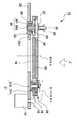
도 1은 본 발명의 제1 실시 형태에 따른 IBE 장치(1)의 전체 구성을 설명하는 도면이며, IBE 장치를 측면으로부터 본 개략 단면도이다.Fig. 1 is a schematic cross-sectional view of an IBE apparatus as viewed from the side, illustrating the overall configuration of an
도 1에 도시한 IBE 장치(1)는 진공 용기(3)와, 방전실(5)과, 인출 전극(4)과, 기판 홀더(11)와, 셔터 장치(9)를 구비하고 있다. 방전실(5)은 도입된 가스에 고주파 전력을 인가함으로써 플라즈마를 발생한다. 인출 전극(4)은 방전실(5)에서 발생한 플라즈마로부터 이온을 진공 용기(3)의 프로세스 공간으로 인출하기 위한 전계를 발생시킨다. 기판 홀더(11)가 기판(2)을 보유 지지하는 셔터 장치(9)는 방전실(5)로부터 기판(2)이 적재되어 있는 프로세스 공간으로 방사되는 이온 빔을 차폐한다. 방전실(5)은 진공 용기(3)의 측면에 연결되어 있다. 기판 홀더(11)는 방전실(5)에 대향해서 배치되어 있다. 방전실(5)로부터 조사되는 이온의 전하를 중화하기 위한 뉴트럴라이저(도시하지 않음)가 프로세스 공간의 측면에 설치되어 있다. 또한, 도시하지 않았지만, 진공 용기(3)에는 게이트 밸브를 통하여 반송실이 연결되어 있고, 그 반송실의 중앙에는 반송 로봇이 설치되어 있다.The
반송 로봇에 의해 반송된 기판(2)은, 기판 홀더(11)의 리프트 핀(16) 상에 놓이고, 그 후, 리프트 핀(16)의 강하에 의해 기판 스테이지(7) 상에 적재된다. 그 후, 정전 척이나 메카니즘 척 등의 고정 수단에 의해, 기판(2)은 기판 스테이지(7)에 고정된다. 리프트 핀(16)은 기판 스테이지(7)의 내부에 설치되고, 기판 스테이지 상에 있어서 기판을 적재하는 것이 가능한 면에 대하여 수직 방향으로 상하 이동이 가능하다. 기판(2)을 지지하기 위해서, 리프트 핀(16)은 적어도 3개로 구성된다. 본 실시 형태에서는, 3개의 리프트 핀의 구성예를 설명하지만, 본 발명의 취지는 이 예에 한정되는 것이 아니고, 3개 이상의 리프트 핀에 대해서도 적용 가능하다.The
도 2는 기판 홀더(11)의 회전 동작을 설명하는 도면이다. 회전 지지부(8)는 진공 용기(3)에 대하여 회전축 A를 중심으로 해서 회전 가능하고, 이 회전(1분간에 약 60회전)에 의해 회전 지지부(8)에 지지되어 있는 기판 스테이지(7)도 회전한다. 또한, 회전 지지부(8)는 회전축 B를 중심으로 해서 기판 스테이지(7)에 보유 지지된 기판 표면의 방향을, 이온 빔에 대하여 바꿀 수 있다. 즉, 회전 지지부(8)의 회전 동작에 의해, 방전실(5)로부터의 이온의 입사 방향에 대한 기판 성막면의 각도를 변화시킬 수 있다. 기판 성막면으로의 이온의 입사 각도를 변화시킴으로써, 기판(2)의 성막면에 경사 방향으로부터 이온을 입사할 수 있고, 고정밀도의 에칭을 행할 수 있다. 이때, 상술한 바와 같이, 기판(2)은 고정 수단에 의해 기판 스테이지(7)에 고정되어 있으므로, 회전 지지부(8)에 의해 기판 스테이지(7)와 함께 이온 빔에 대하여 회전할 수 있다.Fig. 2 is a view for explaining the rotation operation of the
IBE 장치(1)는 기판 홀더(11)에 적재된 기판(2)에 대하여 방전실(5)로부터 이온을 조사하고, 기판(2) 상의 적층막을 에칭한다. 기판 홀더(11)는 회전 지지부(8)에 의해 지지되어 있다. 기판 홀더(11)의 내부에 설치된 정전 척 기구에 의해, 기판(2)은 기판 스테이지(7)에 흡착되어, 보유 지지되어 있다.The
셔터 장치(9)는 방전실(5)과 기판 홀더(11)의 사이에 설치되어 있고 셔터 장치(9)의 개폐 동작에 의해 방전실(5)로부터 기판 홀더(11)에 있어서의 기판 스테이지(7) 상의 기판(2)에 대하여 조사되는 이온을 차폐할 수 있다.The
우선, 방전실(5)은 가스 도입 수단(도시하지 않음)에 의해 도입된 불활성 가스(예를 들어, 아르곤 가스)에 전력을 인가함으로써, 플라즈마를 발생시킨다. 인출 전극(4)은 방전실(5) 내에서 발생한 플라즈마로부터 이온을 끌어내어, 기판(2)을 향해서 조사한다. 소정 시간 이온 빔을 기판(2)에 조사한 후, 셔터 장치(9)가 작동하고, 이온 빔이 차폐되어 에칭이 종료된다. 또한, 플라즈마 발생을 위해서 사용하는 불활성 가스로는 아르곤 가스에 한정되지 않고, 예를 들어 크립톤(Kr) 가스나 크세논(Xe) 가스, 산소(O2) 가스이어도 좋다.First, the
기판 홀더(11)가 다시 반송 위치까지 회동하면, 기판은 리프트 핀에 의해 들어올려져, 반송 로봇으로 주고 받아진다.When the
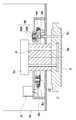
이어서, 도 3 내지 도 8을 참조하여, 본 발명의 특징 부분인 기판 지지 장치(기판 홀더)의 구성을 설명한다. 도 3은 도 1의 x-x 단면에 있어서의 기판 홀더(11)의 구성을 설명하기 위한 측단면도이며, 승강 수단(15)이 동작하기 전, 즉 기판이 기판 스테이지(7)에 적재되어 있는 상태를 나타내고 있다. 도 4는 리프트 핀(16)을 제외한 승강 수단(15)의 상세 사시도이다. 도 5는 제1 회전 부재의 개략 상면도이다. 도 6은 승강 수단(15)의 측단면도이다. 도 7은 승강 수단(15)이 동작 후, 즉 기판을 들어올린 상태를 도시하고 있는 측단면도이다. 도 8은 이동체(볼 나사)(26)의 동작을 설명하기 위한 개략 단면도이다.Next, the configuration of the substrate supporting apparatus (substrate holder), which is a feature part of the present invention, will be described with reference to Figs. 3 to 8. Fig. 3 is a sectional side view for explaining the configuration of the
도 3에 도시되는 기판 스테이지(7)의 하방에는, 기판 스테이지(7)를 지지하는 지주(6)와, 지주(6)를 개재해서 기판을 회전시키기 위한 제1 회전 구동부(14)가 설치되어 있다. 본 실시 형태에서는, 제1 회전 구동부(14)는 회전축 A와 동축의 회전축을 중심으로 회전 가능한 모터에 의해 구성되어 있다. 기판 스테이지(7)의 하방에는 제1 회전 구동부(14)가 설치되어 있기 때문에, 리프트 핀(16)을 승강하는 승강 수단(15)을 구동하기 위한 제2 회전 구동부(17)는, 기판 스테이지(7)의 중앙(회전축 A)으로부터 오프셋한 위치에 배치되어 있다. 또한, 본 실시 형태에서는, 제2 회전 구동부(17)는 회전축 A로부터 오프셋한 회전축을 중심으로 회전 가능한 모터에 의해 구성되어 있다.A
제2 회전 구동부(17)가 회전축 A로부터 오프셋한 위치에 배치되기 때문에, 제2 회전 구동부(17)로부터의 거리에 따라 발생하는 승강 수단(15)의 변형이나 기울기 등의 영향에 의해, 복수의 리프트 핀(16) 각각의 승강량에 편차가 발생할 수 있다. 예를 들어, 제2 회전 구동부(17)에 가까운 위치에 배치되어 있는 리프트 핀에 비하여 먼 위치에 배치되어 있는 리프트 핀은 승강 수단(15)의 기울기의 영향을 받기 쉽다.Since the second
복수의 리프트 핀(16)의 승강량에 편차가 발생할 수 있는 문제를 해결하기 위해서, 승강 수단(15)은 오프셋 배치된 제2 회전 구동부(17)의 회전을, 외측 기어(18)(전달 부재)를 개재해서 회전축 A와 동축에 설치된 제1 회전 부재(19)에 전달하는 구성으로 하고 있다. 제1 회전 부재(19)는 환상의 링 기어이며, 외주측에도, 내주측에도 기어가 형성되어 있다. 외주측에 형성된 기어와 제2 회전 구동부(17)의 회전축에 설치된 외측 기어(18)가 결합함으로써, 제2 회전 구동부(17)의 회전이 제1 회전 부재(링 기어)(19)에 전달되고, 제1 회전 부재(링 기어)(19)가 회전축 A를 회전 중심으로 해서 회전한다. 회전축 A를 회전 중심으로 하는 회전, 즉, 제1 회전 부재(링 기어)(19)의 회전으로 변환된 후, 또한 제1 회전 부재(링 기어)(19)의 회전을 직선 운동으로 변환하고, 이 직선 운동에 의해 리프트 핀(16)을 상하 이동시키고 있다. 회전축 A를 회전 중심으로 하는 제1 회전 부재(링 기어)(19)의 회전을 직선 운동으로 변환함으로써 승강 수단(15)의 기울기 등의 영향에 의한 리프트 핀(16)의 편차를 개선할 수 있다. 이하, 도면을 참조하여 상세하게 설명한다.In order to solve the problem that the lift amount of the plurality of lift pins 16 may occur, the elevating
도 3에 도시한 바와 같이, 기판 홀더(11)는 기판 스테이지(7)와, 지주(6)와, 제1 회전 구동부(14)와, 지지부(10)와, 승강 수단(15)과, 리프트 핀(16)을 구비하고 있다. 지주(6)는 기판 스테이지(7)를 지지한다. 제1 회전 구동부(14)는 지주(6)를 회전시킨다. 승강 수단(15)은 지지부(10)의 내부에 설치되고, 리프트 핀(16)의 승강에 의해 기판 스테이지(7) 상에 적재된 기판(2)을 상하 이동시키는 것이 가능하다.3, the
리프트 핀(16)은, 기판 스테이지(7) 내에 설치되고, 승강 수단(15)의 승강 동작에 의해 승강한다. 리프트 핀(16)의 단부가 기판 스테이지(7)의 기판 적재면보다 높은 위치까지 상승하면, 리프트 핀(16)의 단부에 기판(2)의 이면이 접촉하여 기판(2)을 지지한다. 리프트 핀(16)은 기판(2)을 지지하기 위해서 적어도 3개의 리프트 핀으로 구성된다. 지지부(10)는 지주(6)를 회전 가능한 상태로 지지하는 하우징이다. 지지부(10)는 지주(6)를 삽입하는 것이 가능한 삽입 관통 구멍을 갖는 하우징이며, 그 삽입 관통 구멍에 지주(6)를 삽입함으로써, 기판 스테이지(7)를 회전 가능하게 지지하고 있다. 또한, 지지부(10)는 대기측과 진공측을 분리하는 역할을 담당하고 있고, 지지부(10)의 상부에서 자성 유체 외주 부재(34)와 접속되어 있다. 자성 유체 외주 부재(34)는 지주(6)가 회전할 때 제1 또는 제2 회전 구동 부재 등으로부터 나오는 분진이 프로세스 공간으로 방출되는 것을 효과적으로 예방할 수 있다.The lift pins 16 are provided in the
승강 수단(15)은 지주(6)의 주위에 배치되어 있다. 승강 수단(15)은 제1 회전 부재(19), 제2 회전 구동부(17), 제2 회전 부재(24) 및 이동체(26)를 갖는다. 제1 회전 부재(19)는 제2 회전 구동부(17)의 회전축에 설치된 외측 기어(18)를 개재해서 전달되는 회전에 의해 지주(6)의 주위를 회전한다. 제2 회전 구동부(17)는 제1 회전 부재(19)를 회전시키기 위한 회전 구동을 행한다. 제2 회전 부재(24)는 리프트 핀(16)의 하방에 배치되어, 제1 회전 부재(19)의 회전 동작과 연동해서 회전한다. 제2 회전 부재(24)는 리프트 핀(16)의 하방에 배치된, 적어도 3개의 제2 회전 부재(24a, 24b, 24c)(도 4)에 의해 구성된다. 3개의 제2 회전 부재(24a, 24b, 24c)는 환상의 링 기어이며, 외주측에는 기어가 형성되어 있다. 제2 회전 부재(내측 기어)(24a, 24b, 24c)(도 4) 각각의 내주측에는 너트의 회전을 직선 운동으로 변환하는 것이 가능한 적어도 3개의 이동체(볼 나사)(26)가 설치되어 있다. 제1 회전 부재(링 기어)(19)의 내주측에 형성된 기어와 제2 회전 부재(내측 기어)(24a, 24b, 24c)의 외주측에 형성된 기어가 맞물린다. 제1 회전 부재(링 기어)(19)가 회전하면, 제2 회전 부재(내측 기어)(24a, 24b, 24c)가 회전한다. 제2 회전 부재(내측 기어)(24a, 24b, 24c)의 회전이 이동체(26)의 너트(261)에 전달되어, 볼 나사 축(262)의 둘레를 너트(261)가 회전함으로써, 볼 나사 축(262)이 직선 운동한다. 볼 나사 축(262)의 직선 운동(이동량)은, 볼 나사 축(262)의 나사의 피치와 너트(261)의 회전 수에 의해 정해진다. 제1 회전 부재(링 기어)(19)의 회전에 따라, 제2 회전 부재(내측 기어)(24a, 24b, 24c)룰 개재해서 회전하는 각각의 이동체(볼 나사)(26)의 너트(261)의 회전 수는 동일하다. 동일 피치의 볼 나사 축(262)을 사용하는 경우, 볼 나사 축(262)의 이동량은, 각각의 이동체(볼 나사)(26)에 있어서 동일해진다. 너트(261)의 회전 방향을 전환함으로써, 볼 나사 축(262)의 상하 운동의 방향을 제어할 수 있다. 예를 들어, 컨트롤러(도시하지 않음)는 제2 회전 구동부(17)의 회전 방향을 제어함으로써, 볼 나사 축(262)의 상하 운동의 방향을 제어할 수 있다.The elevating means (15) is arranged around the support (6). The elevating means 15 has a first rotating
이동체(26)의 볼 나사 축(262)의 직선 운동은, 밀어올림 핀(32a, 32b, 32c) (도 4)을 통해서 3개의 리프트 핀(16)에 전달된다. 3개의 리프트 핀(16)은, 밀어올림 핀(32a, 32b, 32c)으로부터 전달된 직선 운동에 의해 상하 이동한다. 제1 회전 구동부(14)는 서보 모터나 스테핑 모터 등에 의해 구성되고, 컨트롤러(도시하지 않음)는 서보 모터나 스테핑 모터 등의 회전 수를 제어 가능하다. 기판 스테이지(7)로부터 기판(2)을 반출할 때, 컨트롤러(도시하지 않음)는 리프트 핀(16)의 바로 아래에 밀어올림 핀(32)이 위치하도록, 기판 스테이지(7)의 회전 위치를 위치 결정 제어할 수 있다. 위치 결정 후, 컨트롤러는 제2 회전 구동부(17)의 회전을 제어하고, 외측 기어(18), 제1 회전 부재(19), 제2 회전 부재(24), 너트(261)를 회전 구동한다. 그리고 이러한 회전 구동으로부터 변환된 볼 나사 축(262) 및 밀어올림 핀(32)의 직선 운동에 의해, 리프트 핀(16)은 상하 이동한다.The linear motion of the
도 6, 도 8에 도시한 바와 같이, 이동체(볼 나사)(26)는 너트(261)와, 볼 나사 축(262)을 갖는다. 너트(261)의 외주측은 제2 회전 부재(24)의 내주에 고정되어 있다. 제2 회전 부재(24)가 회전하면 너트(261)가 회전한다.As shown in Figs. 6 and 8, the moving body (ball screw) 26 has a
도 4에 도시한 바와 같이, 베이스 플레이트(22)의 하면측에는 제2 회전 구동부(17)가 배치되어 있다. 제2 회전 구동부(17)의 회전에 의해, 동기해서 회전하는 외측 기어(18)는 베이스 플레이트(22)의 상면측에 배치되어 있다. 도 5에 도시한 바와 같이, 외측 기어(18)는 제1 회전 부재(링 기어)(19)의 외주측의 기어와 걸림 결합하고 있다. 또한, 제2 회전 부재(내측 기어)(24)는 내측 기어(24)의 중심축과 동축 상에 배치되는 베어링(23)(도 6)에 의해, 제1 회전 부재(링 기어)(19)의 내주측의 기어와 맞물린 상태로 회전 가능하게 보유 지지되어 있다. 제1 회전 부재(링 기어)(19)의 상면측에 고정되어 있는 가이드 링(20)은, 3개의 베어링(21a, 21b 및 21c)에 의해, 기판 스테이지(7)의 회전축(회전축 A) 둘레로 회전 가능하게 보유 지지되어 있다.As shown in Fig. 4, the second
도 4에 도시한 바와 같이 베이스 플레이트(22)의 상면측에는, 제2 회전 부재(내측 기어)(24)(24a, 24b, 24c)가 회전축 A를 중심으로 한 동심원 상에 등간격으로 배치되어 있다. 제2 회전 부재(24a, 24b)의 사이에는 베어링(21b)이 배치되고, 제2 회전 부재(24b, 24c)의 사이에는 베어링(21c)이 배치되어 있다. 그리고, 제2 회전 부재(24a, 24c)의 사이에는 베어링(21a)이 배치되어 있다.4, second rotating members (inner gears) 24 (24a, 24b, and 24c) are disposed on the upper surface side of the
도 6에 도시한 바와 같이, 베어링(21)(21a, b, c)의 외륜(211)의 상부 외주면에는 단부에 곡률을 갖는 볼록부가 형성되어 있고, 이 R 형상의 볼록부는 가이드 링(20) 내주면에 형성된 V형 홈과 접해서 가이드 링(20)의 회전을 지지하고 있다. 가이드 링(20)의 하면측에는 가이드 링(20)의 회전축과 동축의 제1 회전 부재(링 기어)(19)가 고정되어 있다. 제1 회전 부재(링 기어)(19)의 형상(내형, 외형 및 두께)은, 예를 들어 가이드 링(20)의 형상과 동일한 것으로 구성할 수 있다.6, a convex portion having a curvature at an end portion is formed on the outer peripheral surface of the
승강 수단(15)은 대기측으로부터 벨로즈(28)와 일체인 밀어올림 핀(32)을 밀어올리는 것에 의해 진공측의 리프트 핀(16)을 밀어 올린다. 밀어올려진 리프트 핀(16)의 단부가 기판(2)의 이면에 접촉하고, 리프트 핀(16)의 상승에 의해 기판(2)이 들어올려진다(도 7). 또한, 리프트 핀(16)이 강하하면, 기판(2)도 강하하고, 리프트 핀(16)의 단부가 기판 스테이지(7)의 기판 적재면보다 하방으로 강하하면, 리프트 핀(16)에 의해 지지되고 있던 기판(2)이 리프트 핀(16)으로부터 기판 적재면 상에 적재된다(도 3).The lifting means 15 pushes up the
도 6에 도시한 바와 같이, 제2 회전 부재(내측 기어)(24)의 중심축과 동축 상에, 이동체(볼 나사)(26) 및 베어링(23)이 배치되어 있다. 내측 기어(24)와, 이동체(볼 나사)(26)의 너트(261)와, 베어링(23)의 내륜이 서로 고정되어, 제1 회전 부재(링 기어)(19)의 회전에 수반하여, 일체로 회전한다. 베어링(23)의 외륜은 베어링 외주 부재(29)를 개재해서 베이스 플레이트(22)에 고정되어 있고, 제2 회전 부재(내측 기어)(24)는 그 장소에서 회전 가능하게 보유 지지된다. 또한, 도 4에 도시한 바와 같이, 3군데 배치되어 있는 볼 나사 축(262)의 상단부를 링플레이트(27)에 연결함으로써, 도 5에 도시하는 이동체(볼 나사)(26)의 볼 나사 축(262)은 회전이 멈추게 된다. 너트(261)가 회전할 때에 너트(261)와 볼 나사 축(262)이 함께 회전하지 않고, 너트(261)가 회전하고, 이러한 회전에 따라 볼 나사 축(262)이 상하로 이동한다.A moving body (ball screw) 26 and a
제1 회전 부재(링 기어)(19)가 회전하면 제1 회전 부재(19)의 내주측의 기어와 맞물려 있는 제2 회전 부재(내측 기어)(24)는 제1 회전 부재(링 기어)(19)와 동기해서 회전한다. 또한, 본 실시 형태에서는 제2 회전 부재(내측 기어)(24)를 3군데 사용하고 있지만, 본 발명의 취지는 이 예에 한정되는 것이 아니고, 3군데 이상 설치해도 좋다.When the first rotary member (ring gear) 19 is rotated, the second rotary member (inner gear) 24 engaged with the gear on the inner peripheral side of the
상승한 링플레이트(27)에 의해, 벨로즈(28)에 일체로 제작되어 있는 밀어올림 핀(32)을 밀어올림으로써 진공측에 있는 리프트 핀(16)을 밀어올리고, 기판(2)을 들어올린다. 이상 설명한 구성에 의해, 기판 스테이지의 회전축 A보다 오프셋으로 한 위치에 배치된 제2 회전 구동부(17)를 작동시키는 경우에도, 리프트 핀(16)의 상하 이동의 편차를 없애고, 기판(2)을 승강시키는 것이 가능하게 된다.The lifting pins 32 integrally formed on the
볼 나사 축(262)의 바로 위에 밀어올림 핀(32) 및 리프트 핀(16)을 배치하는 것이 보다 바람직하다. 이러한 배치로 함으로써 볼 나사 축(262)에 대하여 모멘트하중이 걸리는 것을 방지할 수 있고, 특히 리니어 부시 등의 직진성을 유지하기 위한 가이드 부재를 보조적으로 사용하지 않아도 이동체(볼 나사)(26)의 현저한 수명 저하를 방지하는 것이 가능하게 된다. 이것은 본 장치의 신뢰성의 향상과 비용의 저감에 대해 효과가 있다.It is more preferable to dispose the push-up
기판 스테이지(7)는 정전 흡착 전극(도시하지 않음)과, 정전 흡착 전극에 전압을 인가하기 위한 전력 도입부(13)와, 기판(2)을 냉각하기 위해서 기판 스테이지(7) 내에 형성된 배관에 냉각수를 도입하기 위한 냉각수 도입부(113)를 구비하고 있다. 회전하는 지주(6)와, 고정된 지지부(10)측에 설치된 자성 유체 외주 부재(34)의 사이에는, 진공 공간과 대기 공간을 분리하기 위한 자성 유체(12)가 설치되어 있다.The
이어서, 본 실시 형태의 기판 홀더(11)를 사용하여, 기판 스테이지(7) 상에 적재되어 있는 기판(2)을 들어올리는 동작을 설명한다. 도 3에 도시한 바와 같이, 제2 회전 구동부(17)가 구동함으로써, 외측 기어(18)도 제2 회전 구동부(17)의 회전축과 동축으로 회전한다. 외측 기어(18)의 회전에 수반하여, 외측 기어(18)와 외륜측에서 맞물리고 있는 제1 회전 부재(링 기어)(19)도 회전축 A(지주(6)의 회전축)를 중심으로 해서 회전하기 시작한다.Next, the operation of lifting the
도 5에 도시한 바와 같이, 제1 회전 부재(링 기어)(19)가 회전함과 동시에 제1 회전 부재(링 기어)(19)의 내주측의 기어와 맞물리고 있는, 3군데의 제2 회전 부재(내측 기어)(24)(24a, 24b, 24c)가 회전한다.(Ring gear) 19 is engaged with the gear on the inner peripheral side of the first rotary member (ring gear) 19 as shown in Fig. 5, The rotating member (inner gear) 24 (24a, 24b, 24c) rotates.
제2 회전 부재(내측 기어)(24)(24a, 24b, 24c)의 회전에 수반하여, 도 6에 도시한 바와 같이, 제2 회전 부재(내측 기어)(24)(24a, 24b, 24c)와 동축 상에 배치되는 이동체(볼 나사)(26)의 너트(261)가 회전한다. 이 너트(261)의 회전 운동은, 볼 나사 축(262)의 직선 운동으로 변환되어 볼 나사 축(262)은 상승한다. 그것에 수반하여, 볼 나사 축(262)과 연결된 링플레이트(27)도 상승한다. 적어도 3군데의 이동체(볼 나사)(26)의 바로 위에 배치되는 적어도 3군데의 벨로즈(28) 저면을, 링플레이트(27)가 밀어올리고, 벨로즈(28)와 일체로 제작되어 있는 밀어올림 핀(32a, 32b, 32c)도 동시에 밀어올려진다. 이렇게 해서 밀어올림 핀(32)은, 벨로즈(28)의 바로 위에 배치되는 적어도 3군데의 리프트 핀(16)을 밀어올릴 수 있다. 마지막으로, 도 6에 도시한 바와 같이 적어도 3군데의 리프트 핀(16)이 기판(2)을 밀어올린다.(Inner gear) 24 (24a, 24b, 24c) as shown in Fig. 6 as the second rotating member (inner gear) 24 (24a, 24b, 24c) And the
(제2 실시 형태)(Second Embodiment)
도 9는, 본 발명에 적용 가능한 제2 실시 형태에 따른 기판 처리 장치의 개략 단면도이다. 이 실시 형태의 기판 처리 장치는, 도 3에 도시한 기판 홀더(11)와 기본적으로는 마찬가지의 구성을 구비한다. 동일한 구성 부재에는 동일한 참조 번호를 붙이고, 그 상세한 설명을 생략한다. 그러나, 본 실시 형태의 기판 처리 장치는, 제1 실시 형태의 기판 지지 장치(기판 홀더)와 상이하게, 지주(6)와 기판 스테이지(7)는 회전하지 않기 때문에, 제1 회전 구동부(14)는 설치되어 있지 않다. 대신, 지주(6)의 하부에는 기판 스테이지(7)의 내부에 설치된 정전 흡착 전극(70)에 전력을 도입하기 위한 전력 도입부(13)가 배치되어 있다. 제2 회전 구동부(17)는 기판 스테이지(7)의 중앙부에 배치할 수 없기 때문에, 제1 실시 형태와 마찬가지로, 기판 스테이지(7)의 중앙부(회전축 A)로부터 오프셋된 위치에 배치되어 있다. 본 실시 형태의 기판 지지 장치(기판 홀더)에서는, 기판 스테이지(7)가 회전하지 않기 때문에, 밀어올림 핀(32)과 리프트 핀(16)을 별체로서 설치할 필요는 없고, 리프트 핀(16)이 기판(2)을 직접 승강할 수 있는 구성으로 되어 있다.9 is a schematic sectional view of a substrate processing apparatus according to a second embodiment applicable to the present invention. The substrate processing apparatus of this embodiment has basically the same configuration as that of the
또한, 제1, 제2 실시 형태에 있어서의 외측 기어(18), 제1 회전 부재(링 기어)(19), 제2 회전 부재(내측 기어)(24)는, 예를 들어 풀리와 타이밍 벨트로 치환해도 같은 것을 실현할 수 있다.The
예를 들어, 외측 기어(18)를 외측 풀리, 제1 회전 부재(19)를 제1 회전 풀리로 치환했을 경우를 상정한다. 이 경우, 외측 풀리와 제1 회전 풀리의 사이를 제1 타이밍 벨트(제1 벨트)로 연결하고, 외측 풀리의 회전을 벨트를 통해서 제1 회전 풀리에 전달하는 것도 가능하다.For example, it is assumed that the
제2 회전 부재(24)를 제2 회전 풀리로 했을 경우, 제1 회전 풀리의 회전은, 제1 회전 풀리와 제2 회전 풀리의 사이를 연결하는 제2 타이밍 벨트(제2 벨트)를 통해서 제2 회전 풀리에 전달하는 것도 가능하다.When the
(제3 실시 형태)(Third Embodiment)
도 10은 제3 실시 형태에 따른 전자 디바이스 제조 장치를 설명하는 상면도이다. 도 10에 도시하는 전자 디바이스 제조 장치(500)는 소위 클러스터화된 처리 시스템이다. 전자 디바이스 제조 장치(500)는 중앙부에 2기의 반송 로봇(510)을 구비한 진공 반송실(506)을 갖고 있다. 진공 반송실(506)의 주위에는, 4개의 PVD(스퍼터링)실(501, 502, 503, 504)과, 2개의 로드 로크실(507, 508)과, 이온 빔 에칭 장치(505)가 각각 게이트 밸브를 통해서 연결되어 있다. 각 실에는 배기 수단이 접속되어 있고, 용기 내를 감압 가능하다. 도 10에 도시하는 이온 빔 에칭 장치(IBE 장치)(1)는 상술한 기판 홀더(11)를 구비하고 있다. 또한, 본 실시 형태의 전자 디바이스 제조 장치는 SEMI/MESC 규격으로, 반송 로봇(510)의 신축 아암이 도달하는 범위는 제약된다. 이 기판 처리 장치의 진공 반송실(506)과의 접속면으로부터, 이온 빔 에칭 장치(505)의 기판 홀더(11)(도 1)의 중심까지의 거리는 규정되어 있다.10 is a top view for explaining an electronic device manufacturing apparatus according to the third embodiment. The electronic
또한, 본 발명의 기판 처리 장치는, 각 실시 형태에서 설명된 어떠한 특징이라도 조합해서 구성할 수 있다.Further, the substrate processing apparatus of the present invention can be configured by combining any feature described in each embodiment.
본 발명은 상기 실시 형태에 제한되는 것이 아니고, 본 발명의 정신 및 범위로부터 이탈하지 않고서 여러 가지 변경 및 변형이 가능하다. 따라서, 본 발명의 범위를 밝히기 위해서 이하의 청구항을 첨부한다.The present invention is not limited to the above-described embodiment, and various changes and modifications can be made without departing from the spirit and scope of the present invention. Accordingly, the following claims are appended to disclose the scope of the invention.
본원은, 2010년 10월 7일 제출된 일본 특허 출원 제2010-227465호를 기초로 해서 우선권을 주장하는 것이며, 그 기재 내용의 전부를 여기에 원용한다.The present application claims priority based on Japanese Patent Application No. 2010-227465 filed on October 7, 2010, the entire contents of which are incorporated herein by reference.
Claims (5)
Translated fromKorean상기 수직 방향에 있어서, 상기 수직 방향의 위치가 보유 지지된 상기 기판 스테이지 위에, 상기 리프트 핀을 상하 이동시키기 위한 승강 수단을 구비하고,
상기 기판 스테이지는, 상기 제1 회전축과 교차하는 제2 회전축을 중심으로 회전하고, 상기 기판 스테이지에 보유 지지된 기판 표면의 방향을 프로세스 소스에 대하여 변경할 수 있고,
상기 승강 수단은,
상기 지주의 주위에 배치되어, 상기 지주의 주위를 상기 제1 회전축의 둘레로 회전하는 제1 회전 부재와,
상기 제1 회전축으로부터 오프셋한 위치에 있는 회전축 둘레로 회전하고, 당해 회전을 전달 부재를 통해 상기 제1 회전 부재에 전달하여, 당해 제1 회전 부재를 회전시키기 위한 제2 회전 구동부와,
상기 제1 회전 부재의 회전과 걸림 결합해서 회전하면서, 또한 상기 리프트 핀의 하측에 배치된, 적어도 3개의 제2 회전 부재와,
상기 제2 회전 부재의 회전에 의해, 직선 운동하는 이동체를 구비하고,
상기 이동체의 직선 운동에 의해, 상기 리프트 핀은 상하 이동하는 것을 특징으로 하는 기판 처리 장치.A first rotation driving part for rotating the support about the first rotation axis; and a second rotation driving part for supporting the support on a surface that is provided inside the substrate stage and on which the substrate can be mounted on the substrate stage And at least three lift pins vertically movable in the vertical direction with respect to the substrate,
And elevating means for moving the lift pin up and down on the substrate stage in which the position in the vertical direction is held in the vertical direction,
The substrate stage may rotate about a second rotation axis intersecting the first rotation axis and change the direction of the substrate surface held on the substrate stage with respect to the process source,
The elevating means includes:
A first rotating member disposed around the strut and rotating about the first rotating shaft around the strut,
A second rotation driving unit for rotating the first rotation member about the rotation axis at a position offset from the first rotation axis and transmitting the rotation to the first rotation member via the transmission member,
At least three second rotary members disposed on the lower side of the lift pins while engaged with the rotation of the first rotary member,
And a moving member that linearly moves by rotation of the second rotating member,
Wherein the lift pin is moved up and down by linear movement of the moving body.
상기 제1 회전 부재는 링 형상을 갖는 부재이며, 당해 링 형상의 외주측 및 내주측에 기어가 형성되어 있는 것을 특징으로 하는 기판 처리 장치.The method according to claim 1,
Wherein the first rotating member is a member having a ring shape, and gears are formed on the outer peripheral side and the inner peripheral side of the ring-like shape.
상기 전달 부재는 상기 제1 회전 부재의 외주측에 형성되어 있는 기어와 걸림 결합하는 기어인 것을 특징으로 하는 기판 처리 장치.3. The method of claim 2,
Wherein the transmitting member is a gear engaged with a gear formed on an outer peripheral side of the first rotating member.
상기 제2 회전 부재의 외주부에는 상기 제1 회전 부재의 내주측에 형성되어 있는 기어와 걸림 결합하는 기어가 형성되어 있는 것을 특징으로 하는 기판 처리 장치.3. The method of claim 2,
And a gear engaged with a gear formed on an inner peripheral side of the first rotary member is formed on an outer peripheral portion of the second rotary member.
Applications Claiming Priority (3)
| Application Number | Priority Date | Filing Date | Title |
|---|---|---|---|
| JPJP-P-2010-227465 | 2010-10-07 | ||
| JP2010227465 | 2010-10-07 | ||
| PCT/JP2011/005254WO2012046397A1 (en) | 2010-10-07 | 2011-09-16 | Substrate processing device |
Publications (2)
| Publication Number | Publication Date |
|---|---|
| KR20130095290A KR20130095290A (en) | 2013-08-27 |
| KR101453233B1true KR101453233B1 (en) | 2014-10-22 |
Family
ID=45927405
Family Applications (1)
| Application Number | Title | Priority Date | Filing Date |
|---|---|---|---|
| KR1020137011362AActiveKR101453233B1 (en) | 2010-10-07 | 2011-09-16 | Substrate processing device |
Country Status (4)
| Country | Link |
|---|---|
| US (1) | US20130220551A1 (en) |
| JP (1) | JP5451895B2 (en) |
| KR (1) | KR101453233B1 (en) |
| WO (1) | WO2012046397A1 (en) |
Cited By (1)
| Publication number | Priority date | Publication date | Assignee | Title |
|---|---|---|---|---|
| KR20160140388A (en)* | 2015-05-27 | 2016-12-07 | 도쿄엘렉트론가부시키가이샤 | Plasma processing apparatus |
Families Citing this family (12)
| Publication number | Priority date | Publication date | Assignee | Title |
|---|---|---|---|---|
| US9853579B2 (en)* | 2013-12-18 | 2017-12-26 | Applied Materials, Inc. | Rotatable heated electrostatic chuck |
| JP6748491B2 (en)* | 2016-06-27 | 2020-09-02 | 東京エレクトロン株式会社 | Method for performing pretreatment for forming copper wiring in recess formed in substrate and processing apparatus |
| TWI656594B (en)* | 2016-12-15 | 2019-04-11 | 辛耘企業股份有限公司 | Substrate processing device |
| US10801593B2 (en) | 2017-04-26 | 2020-10-13 | Paratech, Incorporated | Strut extender mechanism |
| JP7097740B2 (en)* | 2018-04-24 | 2022-07-08 | 東京エレクトロン株式会社 | Film forming equipment and film forming method |
| CN108838611B (en)* | 2018-09-05 | 2024-08-27 | 南京天河汽车零部件股份有限公司 | Light-sensing automatic lifting rotary robot welding workbench and application method thereof |
| US11043251B2 (en)* | 2018-11-30 | 2021-06-22 | Taiwan Semiconductor Manufacturing Company, Ltd. | Magnetic tunnel junction device and method of forming same |
| JP6922882B2 (en)* | 2018-12-27 | 2021-08-18 | 日新イオン機器株式会社 | Board holding device |
| JP2021012944A (en)* | 2019-07-05 | 2021-02-04 | 東京エレクトロン株式会社 | Substrate processing apparatus and substrate delivery method |
| JP7426808B2 (en)* | 2019-11-27 | 2024-02-02 | 株式会社Screenホールディングス | Substrate processing equipment |
| KR102835218B1 (en) | 2022-04-12 | 2025-07-18 | 삼성디스플레이 주식회사 | Exposure device and method of manufacturing display device using the same |
| CN119237247B (en)* | 2024-12-04 | 2025-07-04 | 泰兴市贝特金属制品有限公司 | A production device for processing forklift lifting parts |
Citations (4)
| Publication number | Priority date | Publication date | Assignee | Title |
|---|---|---|---|---|
| JPH1050716A (en)* | 1996-07-30 | 1998-02-20 | Dainippon Screen Mfg Co Ltd | Single wafer type substrate heat treating apparatus |
| JPH1140492A (en)* | 1997-07-18 | 1999-02-12 | Dainippon Screen Mfg Co Ltd | Wafer treating device |
| US20060240542A1 (en)* | 2003-03-12 | 2006-10-26 | Schieve Eric W | Substrate support lift mechanism |
| JP2009059952A (en)* | 2007-08-31 | 2009-03-19 | Canon Machinery Inc | Expand device |
Family Cites Families (11)
| Publication number | Priority date | Publication date | Assignee | Title |
|---|---|---|---|---|
| US5342660A (en)* | 1991-05-10 | 1994-08-30 | Celestech, Inc. | Method for plasma jet deposition |
| US5763020A (en)* | 1994-10-17 | 1998-06-09 | United Microelectronics Corporation | Process for evenly depositing ions using a tilting and rotating platform |
| JP4537566B2 (en)* | 2000-12-07 | 2010-09-01 | 大陽日酸株式会社 | Deposition apparatus with substrate rotation mechanism |
| JP2002212729A (en)* | 2001-01-17 | 2002-07-31 | Hitachi Kokusai Electric Inc | Substrate processing apparatus and semiconductor device manufacturing method |
| US7018555B2 (en)* | 2002-07-26 | 2006-03-28 | Dainippon Screen Mfg. Co., Ltd. | Substrate treatment method and substrate treatment apparatus |
| JP4137711B2 (en)* | 2003-06-16 | 2008-08-20 | 東京エレクトロン株式会社 | Substrate processing apparatus and substrate transfer means positioning method |
| TWI304241B (en)* | 2005-02-04 | 2008-12-11 | Advanced Display Proc Eng Co | Vacuum processing apparatus |
| US7750818B2 (en)* | 2006-11-29 | 2010-07-06 | Adp Engineering Co., Ltd. | System and method for introducing a substrate into a process chamber |
| TWI349720B (en)* | 2007-05-30 | 2011-10-01 | Ind Tech Res Inst | A power-delivery mechanism and apparatus of plasma-enhanced chemical vapor deposition using the same |
| JP2010087473A (en)* | 2008-07-31 | 2010-04-15 | Canon Anelva Corp | Substrate alignment apparatus and substrate processing apparatus |
| JP5485958B2 (en)* | 2011-09-16 | 2014-05-07 | 東京エレクトロン株式会社 | Joining method, program, computer storage medium, joining apparatus and joining system |
- 2011
- 2011-09-16KRKR1020137011362Apatent/KR101453233B1/enactiveActive
- 2011-09-16JPJP2012537565Apatent/JP5451895B2/enactiveActive
- 2011-09-16WOPCT/JP2011/005254patent/WO2012046397A1/ennot_activeCeased
- 2013
- 2013-04-01USUS13/854,563patent/US20130220551A1/ennot_activeAbandoned
Patent Citations (4)
| Publication number | Priority date | Publication date | Assignee | Title |
|---|---|---|---|---|
| JPH1050716A (en)* | 1996-07-30 | 1998-02-20 | Dainippon Screen Mfg Co Ltd | Single wafer type substrate heat treating apparatus |
| JPH1140492A (en)* | 1997-07-18 | 1999-02-12 | Dainippon Screen Mfg Co Ltd | Wafer treating device |
| US20060240542A1 (en)* | 2003-03-12 | 2006-10-26 | Schieve Eric W | Substrate support lift mechanism |
| JP2009059952A (en)* | 2007-08-31 | 2009-03-19 | Canon Machinery Inc | Expand device |
Cited By (2)
| Publication number | Priority date | Publication date | Assignee | Title |
|---|---|---|---|---|
| KR20160140388A (en)* | 2015-05-27 | 2016-12-07 | 도쿄엘렉트론가부시키가이샤 | Plasma processing apparatus |
| KR102489747B1 (en) | 2015-05-27 | 2023-01-17 | 도쿄엘렉트론가부시키가이샤 | Plasma processing apparatus |
Also Published As
| Publication number | Publication date |
|---|---|
| JP5451895B2 (en) | 2014-03-26 |
| US20130220551A1 (en) | 2013-08-29 |
| JPWO2012046397A1 (en) | 2014-02-24 |
| WO2012046397A1 (en) | 2012-04-12 |
| KR20130095290A (en) | 2013-08-27 |
Similar Documents
| Publication | Publication Date | Title |
|---|---|---|
| KR101453233B1 (en) | Substrate processing device | |
| KR102730074B1 (en) | Transfer carrier, vapor deposition apparatus, and manufacturing apparatus of electronic device | |
| JP4244555B2 (en) | Support mechanism for workpiece | |
| JP5984036B2 (en) | A linear vacuum robot with z-motion and multi-joint arm | |
| JP5627599B2 (en) | Transfer arm and transfer robot including the same | |
| KR20040097054A (en) | A method of interchanging substrates | |
| JP5504980B2 (en) | Wafer lift rotation mechanism, stage apparatus, and ion implantation apparatus | |
| TWI820174B (en) | Electrically isolated pin-lifter | |
| JP4031724B2 (en) | Substrate processing method and substrate processing apparatus | |
| KR20200137050A (en) | Placement substrate support with a curved substrate function | |
| JP4645696B2 (en) | Support mechanism and load lock chamber of workpiece | |
| JP2008034553A (en) | Substrate retaining device | |
| TWI868187B (en) | Method of pre aligning carrier, wafer and carrier-wafer combination for throughput efficiency | |
| TWI514446B (en) | Ion implantation method, transfer container and ion implantation device | |
| JP2010076073A (en) | Rotary driving device | |
| US6860711B2 (en) | Semiconductor-manufacturing device having buffer mechanism and method for buffering semiconductor wafers | |
| KR20120115146A (en) | Loading unit and processing system | |
| JP4207530B2 (en) | Conveyance mechanism for workpieces | |
| JP7454714B2 (en) | Substrate processing equipment | |
| KR102651218B1 (en) | Substrate processing apparatus | |
| JPWO2011161888A1 (en) | Conveying device and manufacturing method of conveying device | |
| US8906175B2 (en) | Room temperature bonding apparatus | |
| JP2000323554A (en) | Processing apparatus | |
| WO2019073823A1 (en) | Pod opener | |
| JP2007019216A (en) | Substrate transfer robot |
Legal Events
| Date | Code | Title | Description |
|---|---|---|---|
| A201 | Request for examination | ||
| P11-X000 | Amendment of application requested | St.27 status event code:A-2-2-P10-P11-nap-X000 | |
| P13-X000 | Application amended | St.27 status event code:A-2-2-P10-P13-nap-X000 | |
| PA0105 | International application | St.27 status event code:A-0-1-A10-A15-nap-PA0105 | |
| PA0201 | Request for examination | St.27 status event code:A-1-2-D10-D11-exm-PA0201 | |
| PG1501 | Laying open of application | St.27 status event code:A-1-1-Q10-Q12-nap-PG1501 | |
| E902 | Notification of reason for refusal | ||
| PE0902 | Notice of grounds for rejection | St.27 status event code:A-1-2-D10-D21-exm-PE0902 | |
| E13-X000 | Pre-grant limitation requested | St.27 status event code:A-2-3-E10-E13-lim-X000 | |
| P11-X000 | Amendment of application requested | St.27 status event code:A-2-2-P10-P11-nap-X000 | |
| P13-X000 | Application amended | St.27 status event code:A-2-2-P10-P13-nap-X000 | |
| E701 | Decision to grant or registration of patent right | ||
| PE0701 | Decision of registration | St.27 status event code:A-1-2-D10-D22-exm-PE0701 | |
| GRNT | Written decision to grant | ||
| PR0701 | Registration of establishment | St.27 status event code:A-2-4-F10-F11-exm-PR0701 | |
| PR1002 | Payment of registration fee | St.27 status event code:A-2-2-U10-U12-oth-PR1002 Fee payment year number:1 | |
| PG1601 | Publication of registration | St.27 status event code:A-4-4-Q10-Q13-nap-PG1601 | |
| FPAY | Annual fee payment | Payment date:20170919 Year of fee payment:4 | |
| PR1001 | Payment of annual fee | St.27 status event code:A-4-4-U10-U11-oth-PR1001 Fee payment year number:4 | |
| FPAY | Annual fee payment | Payment date:20180918 Year of fee payment:5 | |
| PR1001 | Payment of annual fee | St.27 status event code:A-4-4-U10-U11-oth-PR1001 Fee payment year number:5 | |
| PR1001 | Payment of annual fee | St.27 status event code:A-4-4-U10-U11-oth-PR1001 Fee payment year number:6 | |
| PR1001 | Payment of annual fee | St.27 status event code:A-4-4-U10-U11-oth-PR1001 Fee payment year number:7 | |
| PR1001 | Payment of annual fee | St.27 status event code:A-4-4-U10-U11-oth-PR1001 Fee payment year number:8 | |
| PR1001 | Payment of annual fee | St.27 status event code:A-4-4-U10-U11-oth-PR1001 Fee payment year number:9 | |
| PR1001 | Payment of annual fee | St.27 status event code:A-4-4-U10-U11-oth-PR1001 Fee payment year number:10 | |
| PR1001 | Payment of annual fee | St.27 status event code:A-4-4-U10-U11-oth-PR1001 Fee payment year number:11 | |
| PR1001 | Payment of annual fee | St.27 status event code:A-4-4-U10-U11-oth-PR1001 Fee payment year number:12 |