KR101452557B1 - Electric Power Steering Apparatus - Google Patents
Electric Power Steering ApparatusDownload PDFInfo
- Publication number
- KR101452557B1 KR101452557B1KR1020110081249AKR20110081249AKR101452557B1KR 101452557 B1KR101452557 B1KR 101452557B1KR 1020110081249 AKR1020110081249 AKR 1020110081249AKR 20110081249 AKR20110081249 AKR 20110081249AKR 101452557 B1KR101452557 B1KR 101452557B1
- Authority
- KR
- South Korea
- Prior art keywords
- housing
- flange
- rack
- mounting flange
- motor housing
- Prior art date
- Legal status (The legal status is an assumption and is not a legal conclusion. Google has not performed a legal analysis and makes no representation as to the accuracy of the status listed.)
- Active
Links
Images


Classifications
- B—PERFORMING OPERATIONS; TRANSPORTING
- B62—LAND VEHICLES FOR TRAVELLING OTHERWISE THAN ON RAILS
- B62D—MOTOR VEHICLES; TRAILERS
- B62D3/00—Steering gears
- B62D3/02—Steering gears mechanical
- B62D3/12—Steering gears mechanical of rack-and-pinion type
- B—PERFORMING OPERATIONS; TRANSPORTING
- B62—LAND VEHICLES FOR TRAVELLING OTHERWISE THAN ON RAILS
- B62D—MOTOR VEHICLES; TRAILERS
- B62D5/00—Power-assisted or power-driven steering
- B62D5/04—Power-assisted or power-driven steering electrical, e.g. using an electric servo-motor connected to, or forming part of, the steering gear
- B62D5/0421—Electric motor acting on or near steering gear
- B62D5/0424—Electric motor acting on or near steering gear the axes of motor and final driven element of steering gear, e.g. rack, being parallel
- B—PERFORMING OPERATIONS; TRANSPORTING
- B62—LAND VEHICLES FOR TRAVELLING OTHERWISE THAN ON RAILS
- B62D—MOTOR VEHICLES; TRAILERS
- B62D5/00—Power-assisted or power-driven steering
- B62D5/04—Power-assisted or power-driven steering electrical, e.g. using an electric servo-motor connected to, or forming part of, the steering gear
Landscapes
- Engineering & Computer Science (AREA)
- Chemical & Material Sciences (AREA)
- Combustion & Propulsion (AREA)
- Transportation (AREA)
- Mechanical Engineering (AREA)
- Power Steering Mechanism (AREA)
Abstract
Translated fromKoreanDescription
Translated fromKorean본 발명은 전동식 동력 보조 조향장치에 관한 것이다. 보다 상세하게는 전동식 동력 보조 조향장치에 있어서, 벨트의 장력을 측정하는 별도의 공정 없이도 벨트의 장력을 정확하게 맞춘 상태로 조립할 수 있게 되고, 모터하우징과 랙하우징의 조립시 공정과 생산 단가를 대폭 줄이면서 동시에 진동과 소음을 줄여 운전자에게 쾌적한 조향감을 제공하는 전동식 동력 보조 조향장치에 관한 것이다.The present invention relates to an electric power assist steering apparatus. More specifically, in an electric power assisted steering apparatus, it is possible to assemble a belt in a state in which the tension of the belt is precisely adjusted without a separate process of measuring the tension of the belt, and to significantly reduce the process cost and the production cost when assembling the motor housing and the rack housing And to provide a comfortable steering feeling to the driver by reducing vibration and noise at the same time.
조향장치는 운전자가 조향 핸들을 돌려 자동차의 진행 방향을 자유로이 바꿀 수 있게 하는 장치로서, 자동차의 앞 바퀴가 선회하는 회전 중심을 임의로 변경하여 운전자가 원하는 방향으로 자동차를 진행시킬 수 있도록 보조하는 장치다.The steering apparatus is a device that allows the driver to freely change the traveling direction of the vehicle by turning the steering wheel, and is a device for assisting the driver to move the vehicle in a desired direction by arbitrarily changing the turning center of the front wheel of the vehicle.
자동차가 정지한 상태에서 바퀴를 조향시키기 위해서는 바퀴와 노면과의 마찰력보다 큰 힘을 주어 핸들을 돌려야 하며, 특히 자동차의 중량이 큰 경우와 바퀴의 폭이 넓은 경우에 노면과의 마찰력이 증가하면 운전자의 조향력은 더욱 증가한다.In order to steer the wheels while the vehicle is stationary, it is necessary to give greater force than the frictional force between the wheels and the road surface to turn the steering wheel. Especially when the weight of the vehicle is large and the width of the wheel is wide, The steering force of the vehicle increases further.
이러한 조향장치에 있어서 운전자의 힘을 덜어주기 위해 동력 보조 조향장치(Power Steering System)가 추가되는데, 자동차의 동력 보조 조향장치로는 유압 펌프의 유압을 이용한 유압식 동력 보조 조향장치(Hydraulic Power Steering Apparatus)가 사용되고 있지만, 1990년대 이후 전기 모터를 이용한 전동식 동력 보조 조향장치(Electric Power Steering Apparatus)가 점차로 보편화되어 가고 있다.In order to relieve the driver's power in such a steering apparatus, a power steering system is added. As a power assist steering device of a vehicle, a hydraulic power steering apparatus (hydraulic power steering apparatus) Electric power steering apparatuses using electric motors have been gradually becoming popular since the 1990s.
기존의 유압식 동력 보조 조향장치는 동력을 보조해 주는 동력원인 유압 펌프가 엔진에 의해 구동되어 조향휠의 회전 여부와 상관없이 항상 에너지를 소모하는 데 비해서 전동식 동력 보조 조향장치는 조향휠이 회전하여 토크가 발생되면 전기 에너지로 구동되는 모터가 조향 보조 동력을 제공한다. 따라서 전동식 동력 보조 조향장치를 사용하는 경우 유압식 동력 보조 조향장치에 비해 에너지 효율을 향상시킬 수 있다.In the conventional hydraulic power assist steering system, the hydraulic pump, which is a power source for assisting the power, is always driven by the engine to consume energy irrespective of whether the steering wheel rotates or not. The electric power assist steering device, A motor driven by electric energy provides steering assist power. Therefore, when using an electric power assisted steering system, energy efficiency can be improved as compared with a hydraulic power assisted steering system.
도 1은 종래 기술에 따른 자동차의 전동식 동력 보조 조향장치의 구성도이고, 도 2는 종래 기술에 따른 모터 풀리 하우징과 랙 하우징의 측면도이다.2 is a side view of a motor pulley housing and a rack housing according to the related art; FIG.
도 1에서 도시하는 바와 같이 일반적으로 자동차의 전동식 동력 보조 조향장치는 조향휠(101)부터 양측 바퀴(108)까지 이어지는 조향 계통(100) 및 조향 계통(100)에 조향 보조 동력을 제공하는 보조 동력 기구(120)를 포함하여 구성된다.1, an electric power assist steering apparatus of an automobile generally includes a
조향 계통(100)은 일측이 조향휠(101)에 연결되어 조향휠(101)과 함께 회전하고 타측은 한 쌍의 유니버설 조인트(103)를 매개로 피니언축(104)에 연결되는 조향축(102)을 포함하여 구성된다. 또한, 피니언축(104)은 랙-피니언 기구부(105)를 통해 랙바(109)에 연결되고, 랙바(109)의 양단은 타이로드(106)와 너클암(107)을 통해 차량의 바퀴(108)에 연결된다.The
랙-피니언 기구부(105)는 피니언축(104)에 형성되어 있는 피니언 기어부(111)와 랙바(109)의 외주면 일측에 형성되어 있는 랙 기어부(112)가 서로 맞물려서 형성되므로 운전자가 조향휠(101)을 조작하면 조향 계통(100)에서 토크가 발생하고, 발생한 토크에 의해서 랙-피니언 기구부(105)와 타이로드(106)를 통하여 바퀴(108)를 조향하게 된다.The rack-and-
보조 동력 기구(120)는 운전자가 조향휠(101)에 가하는 토크를 감지하고 감지된 토크에 비례하는 전기 신호를 출력하는 토크 센서(121)와 토크 센서(121)로부터 전해지는 전기 신호에 기초하여 제어 신호를 발생하는 전자 제어 장치(ECU: Electronic Control Unit, 123), 전자 제어 장치(123)로부터 전해지는 제어 신호에 기초하여 보조 동력을 발생시키는 모터(130) 및 벨트를 매개로 모터(130)에서 발생한 보조 동력을 랙바(109)에 전달하는 벨트식 전동장치(140)를 포함하여 구성된다.The
따라서, 전동식 동력 보조 조향장치는 조향휠(101)의 회전에 의해 발생한 토크가 랙-피니언 기구부(105)를 거쳐서 랙바(109)에 전달되고, 발생된 토크에 따라 모터(130)에서 발생한 보조 동력이 벨트식 전동장치(140)에 의해 볼 스크류부(150)를 거쳐서 랙바(109)에 전달되도록 형성된다. 즉, 조향 계통(100)에서 발생한 토크와 모터(130)에서 발생한 보조 동력이 합쳐져서 랙바(109)를 축 방향으로 운동하도록 하는 것이다.Therefore, the electric power assist steering apparatus is configured such that the torque generated by the rotation of the
또한, 도 2에 도시한 바와 같이 모터(130)는 모터(130)를 감싸는 모터하우징(235)과 랙하우징(207)의 볼트(230) 결합에 의해 고정된다. 조향시 모터축(203)이 회전하면서 벨트(209)를 구동하여 볼너트(205)부위를 회전하게 되면 벨트(209)의 회전에 의해 볼너트(205)가 랙바(109)를 왕복 운동시키게 되어 있다.2, the
이와 같은 종래의 전동식 동력 보조 조향장치는 모터하우징과 랙하우징의 조립시 벨트의 장력을 측정하고, 장력을 조정하는 단계를 거쳐야 해서 조립 공정이 늦어지고, 생산 단가가 올라가는 문제점이 있었다.In such a conventional electric power assisted steering apparatus, when the motor housing and the rack housing are assembled, the tension of the belt is measured and the tension is adjusted, so that the assembling process is delayed and the production cost is increased.
또한, 작업자가 정확하게 벨트 장력을 측정하고 조립하지 않는 경우 벨트의 장력이 높거나 낮아져서 과부하가 걸리거나, 벨트와 구동 풀리, 종동 풀리 사이에서 소음이 발생하며 벨트가 손상되는 문제점이 있었다.In addition, when the operator does not measure and assemble the belt tension accurately, the tension of the belt becomes high or low, causing an overload, or a noise is generated between the belt, the drive pulley and the driven pulley.
본 발명은 전술한 배경에서 안출된 것으로, 전동식 동력 보조 조향장치에 있어서, 벨트의 장력을 측정하는 별도의 공정 없이도 벨트의 장력을 정확하게 맞춘 상태로 조립할 수 있게 되고, 모터하우징과 랙하우징의 조립시 공정과 생산 단가를 대폭 줄이면서 동시에 진동과 소음을 줄여 운전자에게 쾌적한 조향감을 제공하는 전동식 동력 보조 조향장치를 제공하는데 그 목적이 있다.SUMMARY OF THE INVENTION The present invention has been made in view of the above background and it is an object of the present invention to provide an electric power assisted steering apparatus which can assemble the motor in a state in which the tension of the belt is precisely adjusted without any additional step of measuring the tension of the belt, The present invention is directed to an electric power assist steering apparatus that reduces vibration and noise while greatly reducing process and production costs, and provides a comfortable steering feeling to a driver.
이러한 목적을 달성하기 위하여 본 발명은 모터의 구동력을 벨트를 매개로 랙바에 전달하는 것으로, 모터축과 편심되게 형성된 하우징 단부와, 상기 하우징 단부의 외주측에 연장 형성된 체결 플랜지가 구비되어 있는 모터하우징; 상기 하우징 단부가 삽입되는 삽입홀과, 단부의 외주측에 상기 체결 플랜지와 결합되는 마운팅 플랜지가 구비되어 있는 랙하우징; 상기 모터하우징과 랙하우징에 형성되되, 이들의 결합시 상기 벨트의 장력이 셋팅되는 위치에서 결합되도록 형성되는 위치 확인수단을 포함하는 전동식 동력 보조 조향장치를 제공한다.In order to accomplish the above object, the present invention provides a motor housing, which transmits a driving force of a motor to a rack bar via a belt and includes a housing end portion formed to be eccentric with a motor shaft, and a motor housing having a fastening flange extending from an outer periphery of the housing end portion. ; A rack housing having an insertion hole into which the housing end is inserted and a mounting flange coupled with the fastening flange on the outer periphery of the end; And positioning means formed on the motor housing and the rack housing to be coupled to each other at a position where the tension of the belt is set when the motor housing and the rack housing are coupled.
이상에서 설명한 바와 같이 본 발명에 의하면, 전동식 동력 보조 조향장치에 있어서, 벨트의 장력을 측정하는 별도의 공정 없이도 벨트의 장력을 정확하게 맞춘 상태로 조립할 수 있게 되고, 모터하우징과 랙하우징의 조립시 공정과 생산 단가를 대폭 줄이면서 동시에 진동과 소음을 줄여 운전자에게 쾌적한 조향감을 제공하는 효과를 갖게 된다.As described above, according to the present invention, in the electric power assisted steering apparatus, it is possible to assemble the tension of the belt precisely without any additional step of measuring the tension of the belt, so that the assembling process of the motor housing and the rack housing And the production cost is reduced, and at the same time vibration and noise are reduced, thereby providing a pleasant steering feeling to the driver.
도 1은 종래 기술에 따른 자동차의 전동식 동력 보조 조향장치의 구성도,
도 2는 종래 기술에 따른 모터 풀리 하우징과 랙 하우징의 측면도,
도 3은 본 발명에 의한 전동식 동력 보조 조향장치의 일례를 나타내는 분해사시도,
도 4 내지 도 8은 본 발명에 의한 전동식 동력 보조 조향장치의 다양한 실시예를 나타내는 분해 사시도,
도 9는 본 발명에 의한 의한 전동식 동력 보조 조향장치의 결합된 상태를 일례로 나타내는 사시도이다.1 is a configuration diagram of an electric power assisted steering apparatus of an automobile according to the related art,
2 is a side view of a motor pulley housing and a rack housing according to the prior art,
3 is an exploded perspective view showing an example of an electric power assisted steering apparatus according to the present invention,
4 to 8 are exploded perspective views showing various embodiments of the electric power assisted steering apparatus according to the present invention,
FIG. 9 is a perspective view illustrating an example of a coupled state of the electric power assisted steering apparatus according to the present invention.
이하, 본 발명의 일부 실시예들을 예시적인 도면을 통해 상세하게 설명한다. 각 도면의 구성요소들에 참조부호를 부가함에 있어서, 동일한 구성요소들에 대해서는 비록 다른 도면상에 표시되더라도 가능한 한 동일한 부호를 가지도록 하고 있음에 유의해야 한다. 또한, 본 발명을 설명함에 있어, 관련된 공지 구성 또는 기능에 대한 구체적인 설명이 본 발명의 요지를 흐릴 수 있다고 판단되는 경우에는 그 상세한 설명은 생략한다.Hereinafter, some embodiments of the present invention will be described in detail with reference to exemplary drawings. It should be noted that, in adding reference numerals to the constituent elements of the drawings, the same constituent elements are denoted by the same reference symbols as possible even if they are shown in different drawings. In the following description of the present invention, a detailed description of known functions and configurations incorporated herein will be omitted when it may make the subject matter of the present invention rather unclear.
또한, 본 발명의 구성 요소를 설명하는 데 있어서, 제 1, 제 2, A, B, (a), (b) 등의 용어를 사용할 수 있다. 이러한 용어는 그 구성 요소를 다른 구성 요소와 구별하기 위한 것일 뿐, 그 용어에 의해 해당 구성 요소의 본질이나 차례 또는 순서 등이 한정되지 않는다. 어떤 구성 요소가 다른 구성요소에 "연결", "결합" 또는 "접속"된다고 기재된 경우, 그 구성 요소는 그 다른 구성요소에 직접적으로 연결되거나 또는 접속될 수 있지만, 각 구성 요소 사이에 또 다른 구성 요소가 "연결", "결합" 또는 "접속"될 수도 있다고 이해되어야 할 것이다.In describing the components of the present invention, terms such as first, second, A, B, (a), and (b) may be used. These terms are intended to distinguish the constituent elements from other constituent elements, and the terms do not limit the nature, order or order of the constituent elements. When a component is described as being "connected", "coupled", or "connected" to another component, the component may be directly connected to or connected to the other component, It should be understood that an element may be "connected," "coupled," or "connected."
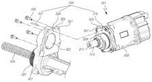
도 3은 본 발명에 의한 전동식 동력 보조 조향장치의 일례를 나타내는 분해사시도, 도 4 내지 도 8은 본 발명에 의한 전동식 동력 보조 조향장치의 다양한 실시예를 나타내는 분해 사시도, 도 9는 본 발명에 의한 의한 전동식 동력 보조 조향장치의 결합된 상태를 일례로 나타내는 사시도이다.Fig. 3 is an exploded perspective view showing an example of the electric power assisted steering apparatus according to the present invention, Figs. 4 to 8 are exploded perspective views showing various embodiments of the electric power assisted steering apparatus according to the present invention, Is a perspective view showing an example of the combined state of the electric power assist steering apparatus according to the present invention.
이들 도면을 도 1 및 도 2와 함께 참조하면, 본 발명에 의한 전동식 동력 보조 조향장치는, 모터(301)의 구동력을 벨트(341)를 매개로 랙바(339)에 전달하는 것으로, 모터축(311)과 편심되게 형성된 하우징 단부(309)와, 하우징 단부(309)의 외주측에 연장 형성된 체결 플랜지(305)가 구비되어 있는 모터하우징(303); 하우징 단부(309)가 삽입되는 삽입홀(323)과, 단부의 외주측에 체결 플랜지(305)와 결합되는 마운팅 플랜지(325)가 구비되어 있는 랙하우징(321); 모터하우징(303)과 랙하우징(321)에 형성되되, 이들의 결합시 벨트(341)의 장력이 셋팅되는 위치에 형성되는 위치 확인수단(330)을 포함하여 구성된다.1 and 2, the electric power assisted steering apparatus according to the present invention transmits the driving force of the
전동식 동력 보조 조향장치는 구동수단과 종동수단을 구비하는데, 구동수단은 전자제어장치(ECU)에 의해 제어되는 모터(301)와, 모터(301)의 축에 결합된 구동풀리(313), 벨트(341) 등으로 이루어진다.The electric power assist steering apparatus includes a drive means and a driven means, which includes a
또한, 종동수단은 랙바(339)를 감싸는 랙하우징(321)의 내부에 랙바(339)를 지지하는 볼너트(343)가 구비되고, 볼너트(343)의 외주면에 별도로 성형되거나 결합된 종동풀리(337)가 구비된다.The driven means is provided with a
모터(301)와 연결된 구동풀리(313)와, 랙바(339)와 연결된 종동풀리(337)는 서로 평행하게 배치되며, 이 구동풀리(313)와 종동풀리(337)에는 벨트(341)가 끼워져 모터(301)의 회전력을 볼너트(343)를 통해 랙바(339)에 전달하고, 볼너트(343)의 동작에 의하여 랙바(339)를 좌우로 이동시켜 조향 보조력을 발생시키게 된다.A
볼너트(343)는 볼을 매개로 랙바(339)와 결합되어 회전하면서 랙바(339)를 랙하우징(321)의 내측에서 슬라이딩시키게 되고, 볼너트(343)의 외주면에는 볼너트(343)를 회전시키는 종동풀리(337)가 장착되어 있어서, 랙바(339)를 축방향으로 슬라이딩시켜 조향 보조력을 발생시킬 수 있도록 되어 있다.The
이렇게 볼너트(343)를 회전시키는 종동풀리(337)는 벨트(341)를 매개로 구동풀리(313)와 연동되어 회전하게 되어 있는데, 조립시 정확한 벨트(341) 장력을 맞추지 않은 경우 벨트(341)의 장력이 낮아 벨트(341)와 풀리 사이에 슬립(Slip)이 발생되거나, 벨트(341)의 장력이 높아 내구성이 떨어지고 과부하가 결리는 등 동력 전달 성능이 떨어지게 된다.The driven
따라서, 종래에는 랙하우징(321)과 모터하우징(303)의 조립시 벨트(341)의 장력을 측정하면서 셋팅된 장력값에 해당되는 위치에서 랙하우징(321)과 모터하우징(303)을 조립하였으나, 본 발명에 있어서는 별도의 벨트 장력 측정 공정 없이 랙하우징(321)과 모터하우징(303)에 구비된 위치 확인수단(330)을 통해 랙하우징(321)과 모터하우징(303)을 결합하는 것만으로 벨트(341)의 장력을 셋팅된 값으로 조립하여 장시간 유지시킬 수 있게 되어 있다.The rack housing 321 and the
위치 확인수단(330)은 도 에 도시된 것처럼 체결 플랜지(305)와 마운팅 플랜지(325)에 형성된 관통홀(315, 329)과, 관통홀(315, 329)에 결합되는 고정부재(331)로 구성될 수 있다.The position checking means 330 includes through
즉, 모터하우징(303)과 랙하우징(321)의 결합시 모터하우징(303)의 하우징 단부(309)를 랙하우징(321)의 삽입홀(323)에 삽입하고 모터축(311)의 끝단에 결합된 구동풀리(313)에 벨트(341)가 연결된 상태에서 위치 확인수단(330)을 통해 벨트(341)의 장력을 셋팅된 위치에서 모터하우징(303)과 랙하우징(321)을 조립하게 된다.That is, the
이렇게 벨트(341)의 장력이 셋팅된 값에 이르는 위치에서 체결 플랜지(305)와 마운팅 플랜지(325)에 구비된 관통홀(315, 329)의 중심이 일치하게 되어 있고, 이 상태에서 관통홀(315, 329)에 고정부재(331)를 결합한 후 체결부재(335)로 모터하우징(303)과 랙하우징(321)을 결합하게 된다.The center of the through
따라서, 작업자는 조립시 일일이 벨트(341)의 장력을 측정하고 난 후에 모터하우징(303)과 랙하우징(321)을 조립하는 번거러움을 없앨 수 있게 된다.Therefore, the operator can eliminate the trouble of assembling the
여기서, 체결 플랜지(305)에 형성된 체결홀(307)과 마운팅 플랜지(325)에 형성된 마운팅홀(327)은 서로 다른 크기로 형성되는데, 체결홀(307)은 체결부재(335)와 나사결합되도록 나사홀로 형성되고, 마운팅홀(327)은 체결홀(307)보다 크게 형성되어 모터하우징(303)의 회전에 의해 미세한 벨트(341)의 장력 셋팅 위치 변화를 수용할 수 있게 되어 있다.The
또한, 위치 확인수단(330)은 도 4에 도시된 것처럼 체결 플랜지(305)와 마운팅 플랜지(325)의 외주측에 음각 또는 양각으로 표시되게 형성될 수 있다.In addition, the positioning means 330 may be formed to be engraved or embossed on the outer circumferential side of the
즉, 모터하우징(303)의 하우징 단부(309)를 삽입홀(323) 내에서 회전시키면서 체결 플랜지(305)와 마운팅 플랜지(325)의 외주측에 음각 또는 양각으로 표시된 직선 형상의 위치 확인수단(330)이 서로 축방향으로 정렬되는 위치까지 모터하우징(303)을 회전시키고, 체결부재(335)로 모터하우징(303)과 랙하우징(321)을 결합할 수 있게 되어 있다.That is, while the
따라서, 작업자는 모터하우징(303)과 랙하우징(321)의 조립시 체결 플랜지(305)와 마운팅 플랜지(325)의 외주측에 표시된 위치 확인수단(330)이 정렬되는 위치에서 모터하우징(303)과 랙하우징(321)을 조립하기만 하면 된다.The operator can move the
그리고, 음각 또는 양각으로 표시된 위치 확인수단(330)은 체결 플랜지(305)와 마운팅 플랜지(325) 중 어느 한쪽이 다른 한쪽보다 폭이 크게 형성되거나, 어느 한쪽이 다수개가 형성되어 있어서, 모터하우징(303)과 랙하우징(321)의 조립시 모터하우징(303)의 조립 오차 범위 즉, 벨트 장력의 셋팅값 허용 범위를 나타내게 할 수 있다.One of the fastening
또한, 위치 확인수단(330)은 도 5에 도시된 것처럼, 체결 플랜지(305)와 마운팅 플랜지(325) 중 어느 하나에 형성되는 돌출부(345)와, 돌출부(345)가 삽입되도록 다른 하나에 형성되는 요홈부(347)로 구성될 수 있는데, 요홈부(347)는 끝단부의 원주면을 따라 길게 형성되며 요홈부(347)의 원주 방향 양단에는 모터하우징(303)의 회전시 돌출부(345)가 지지되는 단턱부(347a)가 구비된다.5, the positioning means 330 may include a
도 5에서는 일례로 돌출부(345)가 랙하우징(321)에 형성되고 요홈부(347)가 모터하우징(303)에 형성된 상태를 도시하였는데, 요홈부(347)는 체결 플랜지(305)의 끝단 외주면에 원주 방향으로 형성되고, 돌출부(345)는 마운팅 플랜지(325)의 끝단에서 돌출되어 요홈부(347)에 삽입되는 형상으로 형성된다.5 shows a state in which the
따라서, 모터하우징(303)과 랙하우징(321)의 결합시 모터하우징(303)의 하우징 단부(309)를 삽입홀(323) 내에서 회전시키면서 돌출부(345)를 요홈부(347)의 단턱부(347a)까지 회전시키고, 체결부재(335)로 모터하우징(303)과 랙하우징(321)을 결합할 수 있게 되어 있다.When the
또한, 도 6에 도시된 것처럼 위치 확인수단(330)은 체결 플랜지(305)와 마운팅 플랜지(325)의 외주측에 서로 맞물림되는 치형으로 형성될 수 있다.6, the positioning means 330 may be formed in a tooth shape that engages with the
즉, 체결 플랜지(305)와 마운팅 플랜지(325)의 외주측을 밀링 머신을 이용해 치형상으로 가공하거나, 수지조성물로 일체로 사출 성형하여 체결 플랜지(305)와 마운팅 플랜지(325)가 결합될 때 위치 확인수단(330)이 서로 맞물림 결합되는 위치에서 조립할 수 있게 되어 있다.That is, when the outer peripheral side of the
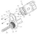
또한, 위치 확인수단(330)은 도 7에 도시된 것처럼 랙하우징(321)의 삽입홀(323) 내주면에 형성되는 요홈부(349)와, 모터하우징(303)의 하우징 단부(309) 외주면에 형성되는 돌기부(351)로 구성될 수 있고, 여기서 요홈부(349)는 끝단부의 원주면을 따라 길게 형성되되, 요홈부(349)의 원주방향 양단에는 모터하우징(303)의 회전시 돌기부(351)가 지지되며 고정되는 단턱부(349a)가 구비된다.7, the position determining means 330 includes a recessed
즉, 랙하우징(321)의 삽입홀(323) 내주면 끝단에 원주 방향의 요홈부(349)를 형성하고, 이에 대응되는 위치인 모터하우징(303)의 하우징 단부(309) 외주면에 돌기부(351)를 형성하여, 모터하우징(303)과 랙하우징(321)의 결합시 모터하우징(303)의 하우징 단부(309)를 삽입홀(323)에 삽입하고 회전시키면서 돌기부(351)를 요홈부(349)의 단턱부(349a)까지 회전시키고, 체결부재(335)로 모터하우징(303)과 랙하우징(321)을 결합할 수 있게 되어 있다.That is, a circumferential recessed
그리고, 도 8에 도시된 것처럼 삽입홀(323)에 형성되는 요홈부(353)는 나선형으로 형성되어 랙하우징(321)과 모터하우징(303)의 결합시 나사 결합 될 수도 있다.8, the recessed
또한, 하우징 단부(309)에 형성되는 돌기부(355)는 요홈부(353)를 따라서 슬라이딩되도록 길이와 폭이 짧은 돌기로 형성되거나, 도 7에 도시된 것처럼 나선형으로 길게 형성되어 랙하우징(321)과 모터하우징(303)의 결합시 나사 결합 될 수도 있다.The
이 경우에는 모터하우징(303)과 랙하우징(321)의 결합시 나사 체결과 같이 모터 하우징을 회전시키기만 하면 되므로, 모터하우징(303)과 랙하우징(321)의 결합시 벨트(341)의 장력 셋팅 위치 확인이 보다 용이하게 이루어질 수 있게 된다.In this case, when the
전술한 바와 같은 본 발명에 의하면, 전동식 동력 보조 조향장치에 있어서, 벨트의 장력을 측정하는 별도의 공정 없이도 벨트의 장력을 정확하게 맞춘 상태로 조립할 수 있게 되고, 모터하우징과 랙하우징의 조립시 공정과 생산 단가를 대폭 줄이면서 동시에 진동과 소음을 줄여 운전자에게 쾌적한 조향감을 제공하는 효과를 갖게 된다.According to the present invention as described above, in the electric power assisted steering apparatus, it is possible to assemble the tension of the belt precisely without any additional step of measuring the tension of the belt, so that the assembling process of the motor housing and the rack housing It is possible to reduce the production cost and reduce vibration and noise at the same time, thereby providing a pleasant steering feeling to the driver.
이상에서, 본 발명의 실시예를 구성하는 모든 구성 요소들이 하나로 결합되거나 결합되어 동작하는 것으로 설명되었다고 해서, 본 발명이 반드시 이러한 실시예에 한정되는 것은 아니다. 즉, 본 발명의 목적 범위 안에서라면, 그 모든 구성 요소들이 하나 이상으로 선택적으로 결합하여 동작할 수도 있다.While the present invention has been described in connection with what is presently considered to be the most practical and preferred embodiments, it is to be understood that the invention is not limited to the disclosed embodiments. That is, within the scope of the present invention, all of the components may be selectively coupled to one or more of them.
또한, 이상에서 기재된 "포함하다", "구성하다" 또는 "가지다" 등의 용어는, 특별히 반대되는 기재가 없는 한, 해당 구성 요소가 내재될 수 있음을 의미하는 것이므로, 다른 구성 요소를 제외하는 것이 아니라 다른 구성 요소를 더 포함할 수 있는 것으로 해석되어야 한다. 기술적이거나 과학적인 용어를 포함한 모든 용어들은, 다르게 정의되지 않는 한, 본 발명이 속하는 기술 분야에서 통상의 지식을 가진 자에 의해 일반적으로 이해되는 것과 동일한 의미를 가진다. 사전에 정의된 용어와 같이 일반적으로 사용되는 용어들은 관련 기술의 문맥 상의 의미와 일치하는 것으로 해석되어야 하며, 본 발명에서 명백하게 정의하지 않는 한, 이상적이거나 과도하게 형식적인 의미로 해석되지 않는다.It is also to be understood that the terms such as " comprises, "" comprising," or "having ", as used herein, mean that a component can be implanted unless specifically stated to the contrary. But should be construed as including other elements. All terms, including technical and scientific terms, have the same meaning as commonly understood by one of ordinary skill in the art to which this invention belongs, unless otherwise defined. Commonly used terms, such as predefined terms, should be interpreted to be consistent with the contextual meanings of the related art, and are not to be construed as ideal or overly formal, unless expressly defined to the contrary.
이상의 설명은 본 발명의 기술 사상을 예시적으로 설명한 것에 불과한 것으로서, 본 발명이 속하는 기술 분야에서 통상의 지식을 가진 자라면 본 발명의 본질적인 특성에서 벗어나지 않는 범위에서 다양한 수정 및 변형이 가능할 것이다. 따라서, 본 발명에 개시된 실시예들은 본 발명의 기술 사상을 한정하기 위한 것이 아니라 설명하기 위한 것이고, 이러한 실시예에 의하여 본 발명의 기술 사상의 범위가 한정되는 것은 아니다. 본 발명의 보호 범위는 아래의 청구범위에 의하여 해석되어야 하며, 그와 동등한 범위 내에 있는 모든 기술 사상은 본 발명의 권리범위에 포함되는 것으로 해석되어야 할 것이다.The foregoing description is merely illustrative of the technical idea of the present invention, and various changes and modifications may be made by those skilled in the art without departing from the essential characteristics of the present invention. Therefore, the embodiments disclosed in the present invention are intended to illustrate rather than limit the scope of the present invention, and the scope of the technical idea of the present invention is not limited by these embodiments. The scope of protection of the present invention should be construed according to the following claims, and all technical ideas falling within the scope of the same shall be construed as falling within the scope of the present invention.
301: 모터303: 모터하우징
305: 체결 플랜지309: 하우징 단부
311: 모터축313: 구동풀리
321: 랙하우징323: 삽입홀
325: 마운팅 플랜지330: 위치 확인수단
337: 종동풀리339: 랙바
341: 벨트301: Motor 303: Motor housing
305: fastening flange 309: housing end
311: motor shaft 313: drive pulley
321: rack housing 323: insertion hole
325: Mounting flange 330: Positioning means
337: a driven pulley 339: a rack bar
341: Belt
Claims (11)
Translated fromKorean모터축과 편심되게 형성된 하우징 단부와, 상기 하우징 단부의 외주측에 체결 플랜지가 구비되어 있는 모터하우징;
상기 하우징 단부가 삽입되는 삽입홀과, 단부의 외주측에 상기 체결 플랜지와 결합되는 마운팅 플랜지가 구비되어 있는 랙하우징;
상기 모터하우징과 랙하우징에 형성되되, 이들의 결합시 벨트의 장력이 셋팅되는 위치에 형성되는 위치 확인수단;
을 포함하는 전동식 동력 보조 조향장치.By transmitting the driving force of the motor to the rack bar via the belt,
A motor housing having a housing end portion eccentrically formed with the motor shaft, and a fastening flange provided on an outer periphery side of the housing end portion;
A rack housing having an insertion hole into which the housing end is inserted and a mounting flange coupled with the fastening flange on the outer periphery of the end;
Positioning means formed on the motor housing and the rack housing at a position where a tension of the belt is set when the motor housing and the rack housing are coupled with each other;
And an electric power assisted steering device.
상기 위치 확인수단은,
상기 체결 플랜지와 마운팅 플랜지에 형성된 관통홀과, 상기 관통홀에 결합되는 고정부재로 구성되는 것을 특징으로 하는 전동식 동력 보조 조향장치.The method according to claim 1,
Wherein the positioning means comprises:
A through hole formed in the fastening flange and the mounting flange, and a fastening member coupled to the through hole.
상기 위치 확인수단은,
상기 체결 플랜지와 마운팅 플랜지의 외주측에 음각 또는 양각으로 표시되는 것을 특징으로 하는 전동식 동력 보조 조향장치.The method according to claim 1,
Wherein the positioning means comprises:
Wherein the engaging flange and the mounting flange are indicated by an engraved or embossed shape on an outer circumferential side of the fastening flange and the mounting flange.
상기 위치 확인수단은,
상기 체결 플랜지와 마운팅 플랜지 중 어느 한쪽이 다른 한쪽보다 폭이 크게 형성되는 것을 특징으로 하는 전동식 동력 보조 조향장치.The method of claim 3,
Wherein the positioning means comprises:
Wherein one of the fastening flange and the mounting flange is formed to be wider than the other of the fastening flange and the mounting flange.
상기 위치 확인수단은,
상기 체결 플랜지와 마운팅 플랜지 중 어느 하나에 형성되는 돌출부와, 다른 하나에 형성되되 상기 돌출부가 삽입되는 요홈부로 구성되는 것을 특징으로 하는 전동식 동력 보조 조향장치.The method according to claim 1,
Wherein the positioning means comprises:
And a protrusion formed on one of the fastening flange and the mounting flange and a groove formed on the other of the fastening flange and the mounting flange and into which the protrusion is inserted.
상기 요홈부는 끝단부의 원주면을 따라 길게 형성되되, 양단에는 상기 모터하우징의 회전시 상기 돌출부가 지지되는 단턱부가 구비되는 것을 특징으로 하는 전동식 동력 보조 조향장치.6. The method of claim 5,
Wherein the recess is formed along the circumferential surface of the end portion, and both ends thereof are provided with a step portion at which the protrusion is supported when the motor housing rotates.
상기 위치 확인수단은,
상기 체결 플랜지와 마운팅 플랜지의 외주측에 서로 맞물림되는 치형으로 형성되는 것을 특징으로 하는 전동식 동력 보조 조향장치.The method according to claim 1,
Wherein the positioning means comprises:
Wherein the coupling member is formed in a tooth shape that engages with the outer peripheral side of the coupling flange and the mounting flange.
상기 위치 확인수단은, 상기 체결 플랜지와 마운팅 플랜지의 외주측을 치형상으로 가공하거나, 수지조성물로 일체로 성형되는 것을 특징으로 하는 전동식 동력 보조 조향장치.8. The method of claim 7,
Wherein the position confirming means is formed into a tooth shape on the outer peripheral side of the fastening flange and the mounting flange, or is integrally formed of a resin composition.
상기 위치 확인수단은,
상기 랙하우징의 삽입홀 내주면에 형성되는 요홈부와, 상기 모터하우징의 하우징 단부 외주면에 형성되는 돌기부로 구성되는 것을 특징으로 하는 전동식 동력 보조 조향장치.The method according to claim 1,
Wherein the positioning means comprises:
A recessed portion formed on an inner circumferential surface of the insertion hole of the rack housing and a protruding portion formed on the outer circumferential surface of the housing end portion of the motor housing.
상기 요홈부는 끝단부의 원주면을 따라 길게 형성되되, 상기 요홈부의 끝단에는 상기 모터하우징의 회전시 상기 돌기부가 지지되는 단턱부가 구비되는 것을 특징으로 하는 전동식 동력 보조 조향장치.10. The method of claim 9,
Wherein the recess is elongated along the circumferential surface of the end portion, and an end of the recess portion is provided with a step portion for supporting the protrusion when the motor housing rotates.
상기 요홈부와 돌기부는 나선형으로 형성되어 상기 랙하우징과 모터하우징의 결합시 나사 결합 되는 것을 특징으로 하는 전동식 동력 보조 조향장치.
10. The method of claim 9,
Wherein the recessed portion and the protruding portion are formed in a spiral shape, and are screwed when the rack housing and the motor housing are engaged.
Priority Applications (4)
| Application Number | Priority Date | Filing Date | Title |
|---|---|---|---|
| KR1020110081249AKR101452557B1 (en) | 2011-08-16 | 2011-08-16 | Electric Power Steering Apparatus |
| US13/586,661US8950543B2 (en) | 2011-08-16 | 2012-08-15 | Electric power steering apparatus |
| CN201210291149.0ACN102951195B (en) | 2011-08-16 | 2012-08-16 | Electric power steering apparatus |
| DE102012016312.6ADE102012016312B4 (en) | 2011-08-16 | 2012-08-16 | Electric power steering device |
Applications Claiming Priority (1)
| Application Number | Priority Date | Filing Date | Title |
|---|---|---|---|
| KR1020110081249AKR101452557B1 (en) | 2011-08-16 | 2011-08-16 | Electric Power Steering Apparatus |
Publications (2)
| Publication Number | Publication Date |
|---|---|
| KR20130019217A KR20130019217A (en) | 2013-02-26 |
| KR101452557B1true KR101452557B1 (en) | 2014-10-21 |
Family
ID=47625356
Family Applications (1)
| Application Number | Title | Priority Date | Filing Date |
|---|---|---|---|
| KR1020110081249AActiveKR101452557B1 (en) | 2011-08-16 | 2011-08-16 | Electric Power Steering Apparatus |
Country Status (4)
| Country | Link |
|---|---|
| US (1) | US8950543B2 (en) |
| KR (1) | KR101452557B1 (en) |
| CN (1) | CN102951195B (en) |
| DE (1) | DE102012016312B4 (en) |
Families Citing this family (54)
| Publication number | Priority date | Publication date | Assignee | Title |
|---|---|---|---|---|
| KR101381047B1 (en)* | 2011-05-25 | 2014-04-14 | 주식회사 만도 | Rack Assist Type Electric Power Steering Apparatus |
| EP2907730B1 (en) | 2014-01-29 | 2017-09-06 | Steering Solutions IP Holding Corporation | Hands on steering wheel detect |
| KR101624074B1 (en)* | 2015-01-12 | 2016-05-24 | 주식회사 만도 | Rack Assist Type Electric Power Steering System |
| JP6421607B2 (en)* | 2015-01-15 | 2018-11-14 | 株式会社ジェイテクト | Steering device |
| KR102222578B1 (en)* | 2015-01-30 | 2021-03-05 | 주식회사 만도 | Electric Power Steering Apparatus |
| KR102242944B1 (en)* | 2015-01-30 | 2021-04-21 | 주식회사 만도 | Rack Assist Type Electric Power Steering System |
| US10589774B2 (en) | 2015-05-01 | 2020-03-17 | Steering Solutions Ip Holding Corporation | Counter rotation steering wheel |
| US10351159B2 (en) | 2015-05-01 | 2019-07-16 | Steering Solutions Ip Holding Corporation | Retractable steering column with a radially projecting attachment |
| US9919724B2 (en) | 2015-05-29 | 2018-03-20 | Steering Solutions Ip Holding Corporation | Retractable steering column with manual retrieval |
| US11560169B2 (en) | 2015-06-11 | 2023-01-24 | Steering Solutions Ip Holding Corporation | Retractable steering column system and method |
| US10343706B2 (en) | 2015-06-11 | 2019-07-09 | Steering Solutions Ip Holding Corporation | Retractable steering column system, vehicle having the same, and method |
| DE102016110791A1 (en) | 2015-06-15 | 2016-12-15 | Steering Solutions Ip Holding Corporation | Gesture control for a retractable steering wheel |
| CN106256651B (en) | 2015-06-16 | 2019-06-04 | 操纵技术Ip控股公司 | Retractable steering column assembly and method |
| KR102216192B1 (en)* | 2015-06-19 | 2021-02-16 | 현대모비스 주식회사 | Power steering apparatus |
| US9828016B2 (en) | 2015-06-24 | 2017-11-28 | Steering Solutions Ip Holding Corporation | Retractable steering column system, vehicle having the same, and method |
| US20160375931A1 (en) | 2015-06-25 | 2016-12-29 | Steering Solutions Ip Holding Corporation | Rotation control system for a steering wheel and method |
| DE102016111473A1 (en) | 2015-06-25 | 2016-12-29 | Steering Solutions Ip Holding Corporation | STATIONARY STEERING WHEEL ASSEMBLY AND METHOD |
| US10112639B2 (en) | 2015-06-26 | 2018-10-30 | Steering Solutions Ip Holding Corporation | Vehicle steering arrangement and method of making same |
| US9840271B2 (en) | 2015-06-29 | 2017-12-12 | Steering Solutions Ip Holding Corporation | Retractable steering column with rake limiter |
| DE102016113803A1 (en)* | 2015-07-28 | 2017-02-02 | Steering Solutions Ip Holding Corporation | PULLEY ASSEMBLY WITH IDLE ROLL, POWER SUPPORT SYSTEM WITH PULLEY ASSEMBLY AND METHOD |
| US9849904B2 (en) | 2015-07-31 | 2017-12-26 | Steering Solutions Ip Holding Corporation | Retractable steering column with dual actuators |
| US9845106B2 (en)* | 2015-08-31 | 2017-12-19 | Steering Solutions Ip Holding Corporation | Overload protection for belt drive mechanism |
| US10160472B2 (en) | 2015-10-20 | 2018-12-25 | Steering Solutions Ip Holding Corporation | Steering column with stationary hub |
| US9809155B2 (en) | 2015-10-27 | 2017-11-07 | Steering Solutions Ip Holding Corporation | Retractable steering column assembly having lever, vehicle having retractable steering column assembly, and method |
| US10029725B2 (en) | 2015-12-03 | 2018-07-24 | Steering Solutions Ip Holding Corporation | Torque feedback system for a steer-by-wire vehicle, vehicle having steering column, and method of providing feedback in vehicle |
| KR102510862B1 (en)* | 2016-01-22 | 2023-03-17 | 에이치엘만도 주식회사 | Electronic power steering apparatus |
| US10496102B2 (en) | 2016-04-11 | 2019-12-03 | Steering Solutions Ip Holding Corporation | Steering system for autonomous vehicle |
| DE102017108692B4 (en) | 2016-04-25 | 2024-09-26 | Steering Solutions Ip Holding Corporation | Control of an electric power steering system using system state predictions |
| US10351161B2 (en) | 2016-05-27 | 2019-07-16 | Steering Solutions Ip Holding Corporation | Steering column with manual retraction |
| CN107521547B (en) | 2016-06-21 | 2020-03-10 | 操纵技术Ip控股公司 | Self-locking telescopic actuator for steering column assembly |
| US10457313B2 (en) | 2016-06-28 | 2019-10-29 | Steering Solutions Ip Holding Corporation | ADAS wheel locking device |
| US10363958B2 (en) | 2016-07-26 | 2019-07-30 | Steering Solutions Ip Holding Corporation | Electric power steering mode determination and transitioning |
| US10160477B2 (en) | 2016-08-01 | 2018-12-25 | Steering Solutions Ip Holding Corporation | Electric power steering column assembly |
| US10189496B2 (en) | 2016-08-22 | 2019-01-29 | Steering Solutions Ip Holding Corporation | Steering assembly having a telescope drive lock assembly |
| US10384708B2 (en) | 2016-09-12 | 2019-08-20 | Steering Solutions Ip Holding Corporation | Intermediate shaft assembly for steer-by-wire steering system |
| US10160473B2 (en) | 2016-09-13 | 2018-12-25 | Steering Solutions Ip Holding Corporation | Steering column decoupling system |
| JP2018048606A (en)* | 2016-09-23 | 2018-03-29 | アイシン精機株式会社 | Pump system |
| US10399591B2 (en) | 2016-10-03 | 2019-09-03 | Steering Solutions Ip Holding Corporation | Steering compensation with grip sensing |
| US10239552B2 (en) | 2016-10-14 | 2019-03-26 | Steering Solutions Ip Holding Corporation | Rotation control assembly for a steering column |
| US10481602B2 (en) | 2016-10-17 | 2019-11-19 | Steering Solutions Ip Holding Corporation | Sensor fusion for autonomous driving transition control |
| US10310605B2 (en) | 2016-11-15 | 2019-06-04 | Steering Solutions Ip Holding Corporation | Haptic feedback for steering system controls |
| US10421475B2 (en) | 2016-11-15 | 2019-09-24 | Steering Solutions Ip Holding Corporation | Electric actuator mechanism for retractable steering column assembly with manual override |
| US9862403B1 (en) | 2016-11-29 | 2018-01-09 | Steering Solutions Ip Holding Corporation | Manually retractable steering column assembly for autonomous vehicle |
| US10351160B2 (en) | 2016-11-30 | 2019-07-16 | Steering Solutions Ip Holding Corporation | Steering column assembly having a sensor assembly |
| US10780915B2 (en) | 2016-12-07 | 2020-09-22 | Steering Solutions Ip Holding Corporation | Vehicle steering system having a user experience based automated driving to manual driving transition system and method |
| US10370022B2 (en) | 2017-02-13 | 2019-08-06 | Steering Solutions Ip Holding Corporation | Steering column assembly for autonomous vehicle |
| US10385930B2 (en) | 2017-02-21 | 2019-08-20 | Steering Solutions Ip Holding Corporation | Ball coupling assembly for steering column assembly |
| US10449927B2 (en) | 2017-04-13 | 2019-10-22 | Steering Solutions Ip Holding Corporation | Steering system having anti-theft capabilities |
| US10780912B2 (en)* | 2017-07-12 | 2020-09-22 | Jtekt Corporation | Steering device |
| US10875566B2 (en) | 2018-03-22 | 2020-12-29 | Steering Solutions Ip Holding Corporation | Stow release assembly for a manually adjustable steering column assembly |
| US10974756B2 (en) | 2018-07-31 | 2021-04-13 | Steering Solutions Ip Holding Corporation | Clutch device latching system and method |
| KR102427344B1 (en)* | 2018-10-26 | 2022-07-29 | 현대모비스 주식회사 | Steering device for vehicle |
| JP7205377B2 (en)* | 2019-05-20 | 2023-01-17 | トヨタ自動車株式会社 | self-driving vehicle |
| US12391303B2 (en) | 2022-03-16 | 2025-08-19 | Robert Bosch Gmbh | Interface for EPS servo unit |
Citations (4)
| Publication number | Priority date | Publication date | Assignee | Title |
|---|---|---|---|---|
| JP2005145431A (en) | 2003-10-24 | 2005-06-09 | Showa Corp | Electric power steering device |
| KR20070044731A (en)* | 2005-10-25 | 2007-04-30 | 주식회사 만도 | Belt Type Electric Power Assist Steering |
| JP3950696B2 (en) | 2002-01-29 | 2007-08-01 | 株式会社ジェイテクト | Electric power steering device |
| KR20120130650A (en)* | 2011-05-23 | 2012-12-03 | 현대모비스 주식회사 | Tension-adjustable power steering device |
Family Cites Families (19)
| Publication number | Priority date | Publication date | Assignee | Title |
|---|---|---|---|---|
| KR100625072B1 (en)* | 2002-01-29 | 2006-09-19 | 가부시키가이샤 제이텍트 | Electric power steering system |
| US20050133297A1 (en)* | 2002-08-22 | 2005-06-23 | Nsk Ltd. | Electric power steering apparatus |
| JP4145158B2 (en)* | 2003-02-03 | 2008-09-03 | 株式会社ジェイテクト | Electric power steering device |
| JP4089781B2 (en)* | 2003-04-15 | 2008-05-28 | 株式会社ジェイテクト | Electric power steering device |
| US7591204B2 (en)* | 2003-05-06 | 2009-09-22 | Nsk Ltd. | Belt speed reducing apparatus for electric power steering apparatus and electric power steering apparatus |
| JP2006027577A (en) | 2004-07-22 | 2006-02-02 | Kayaba Ind Co Ltd | Electric power steering device |
| US20090120712A1 (en)* | 2005-07-11 | 2009-05-14 | Keiji Kashimoto | Electric Power Steering Device |
| KR20070042632A (en)* | 2005-10-19 | 2007-04-24 | 주식회사 만도 | Belt-type transmission and electric power steering of automobile with same |
| DE102005051220A1 (en) | 2005-10-26 | 2007-05-03 | Zf Lenksysteme Gmbh | Power steering |
| EP1792804A1 (en)* | 2005-12-01 | 2007-06-06 | Mando Corporation | Motor-driven power steering system for a vehicle with a device for adjusting the tension of a transmission belt |
| EP2006185B1 (en)* | 2006-04-11 | 2016-07-20 | NSK Ltd. | Electric power steering device and method of assembling the same |
| US7886865B2 (en)* | 2006-04-11 | 2011-02-15 | Nsk Ltd. | Electric power steering apparatus |
| EP1886899A1 (en)* | 2006-08-10 | 2008-02-13 | Mando Corporation | Electric power steering apparatus equipped with a mechanism for adjusting the tension of a transmission belt |
| DE102007008246B4 (en) | 2007-02-20 | 2009-09-24 | Brose Fahrzeugteile GmbH & Co. Kommanditgesellschaft, Würzburg | Device for tensioning the belt of an electric steering drive |
| EP1990258A3 (en)* | 2007-05-08 | 2012-06-27 | Jtekt Corporation | Electric power steering apparatus |
| DE102007000955A1 (en) | 2007-10-01 | 2009-04-02 | Zf Lenksysteme Gmbh | Electrical servo-steering mechanism i.e. rack and pinion servo-assisted steering system for passenger car, has securing unit has openings in housings of electrical servo actuator and steering gear, respectively |
| JP4512128B2 (en)* | 2007-10-25 | 2010-07-28 | 本田技研工業株式会社 | Motor rotation angle detection device |
| NL2003223A (en) | 2008-09-30 | 2010-03-31 | Asml Netherlands Bv | Projection system, lithographic apparatus, method of postitioning an optical element and method of projecting a beam of radiation onto a substrate. |
| CN102123902A (en)* | 2009-10-30 | 2011-07-13 | 日本精工株式会社 | Electric power steering device |
- 2011
- 2011-08-16KRKR1020110081249Apatent/KR101452557B1/enactiveActive
- 2012
- 2012-08-15USUS13/586,661patent/US8950543B2/enactiveActive
- 2012-08-16CNCN201210291149.0Apatent/CN102951195B/enactiveActive
- 2012-08-16DEDE102012016312.6Apatent/DE102012016312B4/enactiveActive
Patent Citations (4)
| Publication number | Priority date | Publication date | Assignee | Title |
|---|---|---|---|---|
| JP3950696B2 (en) | 2002-01-29 | 2007-08-01 | 株式会社ジェイテクト | Electric power steering device |
| JP2005145431A (en) | 2003-10-24 | 2005-06-09 | Showa Corp | Electric power steering device |
| KR20070044731A (en)* | 2005-10-25 | 2007-04-30 | 주식회사 만도 | Belt Type Electric Power Assist Steering |
| KR20120130650A (en)* | 2011-05-23 | 2012-12-03 | 현대모비스 주식회사 | Tension-adjustable power steering device |
Also Published As
| Publication number | Publication date |
|---|---|
| US20130043088A1 (en) | 2013-02-21 |
| US8950543B2 (en) | 2015-02-10 |
| DE102012016312B4 (en) | 2024-05-23 |
| KR20130019217A (en) | 2013-02-26 |
| CN102951195B (en) | 2015-04-29 |
| CN102951195A (en) | 2013-03-06 |
| DE102012016312A1 (en) | 2013-02-21 |
Similar Documents
| Publication | Publication Date | Title |
|---|---|---|
| KR101452557B1 (en) | Electric Power Steering Apparatus | |
| US7637348B2 (en) | Electric power steering apparatus equipped with tension adjusting mechanism | |
| KR101271324B1 (en) | Reducer of Electric Power Steering Apparatus | |
| KR101450326B1 (en) | Belt Type Driveline and Rack Assist Type Electric Power Steering Apparatus having The Same | |
| KR101400488B1 (en) | Reducer and electric power steering apparatus having the same | |
| US9108666B2 (en) | Steering system in a vehicle | |
| KR20130048837A (en) | Rack assist type steering apparatus and rack assist type electric power steering apparatus having the same | |
| EP2418141A1 (en) | Shaft coupling structure | |
| KR20170027176A (en) | Power Transmission Device of Electric Power Steering Apparatus | |
| KR20170040493A (en) | Rack Assist Type Electric Power Steering Apparatus | |
| KR20150029943A (en) | Troque Sensor of Electronic Power Steering Apparatus | |
| JP2013195333A (en) | Electrically-driven power steering device | |
| KR101085336B1 (en) | Electric power assist steering of automobile with damping coupler with serration | |
| KR101124840B1 (en) | Reducer of Electronic Power Steering Apparatus and Electronic Power Steering Apparatus having The Same | |
| KR101584612B1 (en) | Torque Angle Sensor Module of Electronic Power Steering Apparatus | |
| KR20170026875A (en) | Electric Power Steering Apparatus | |
| JP2005022634A (en) | Electric power steering device | |
| KR101427451B1 (en) | Belt Tension Regulator of Electric Power Steering Apparatus and Electric Power Steering Apparatus having The Same | |
| JP4093022B2 (en) | Electric power steering device | |
| JP2007190969A (en) | Electric power steering device | |
| KR102325798B1 (en) | Electric Power Steering Apparatus | |
| KR101424849B1 (en) | Reducer of Electrical Power Steering Apparatus and Electrical Power Steering Apparatus having The Same | |
| KR20170019631A (en) | Steering Column for Vehicle | |
| KR102508009B1 (en) | Steering Column for Vehicle | |
| JP2014061754A (en) | Electric power steering device |
Legal Events
| Date | Code | Title | Description |
|---|---|---|---|
| PA0109 | Patent application | St.27 status event code:A-0-1-A10-A12-nap-PA0109 | |
| P11-X000 | Amendment of application requested | St.27 status event code:A-2-2-P10-P11-nap-X000 | |
| P13-X000 | Application amended | St.27 status event code:A-2-2-P10-P13-nap-X000 | |
| R15-X000 | Change to inventor requested | St.27 status event code:A-3-3-R10-R15-oth-X000 | |
| R16-X000 | Change to inventor recorded | St.27 status event code:A-3-3-R10-R16-oth-X000 | |
| A201 | Request for examination | ||
| PA0201 | Request for examination | St.27 status event code:A-1-2-D10-D11-exm-PA0201 | |
| PG1501 | Laying open of application | St.27 status event code:A-1-1-Q10-Q12-nap-PG1501 | |
| D13-X000 | Search requested | St.27 status event code:A-1-2-D10-D13-srh-X000 | |
| D14-X000 | Search report completed | St.27 status event code:A-1-2-D10-D14-srh-X000 | |
| E902 | Notification of reason for refusal | ||
| PE0902 | Notice of grounds for rejection | St.27 status event code:A-1-2-D10-D21-exm-PE0902 | |
| P11-X000 | Amendment of application requested | St.27 status event code:A-2-2-P10-P11-nap-X000 | |
| P13-X000 | Application amended | St.27 status event code:A-2-2-P10-P13-nap-X000 | |
| E701 | Decision to grant or registration of patent right | ||
| PE0701 | Decision of registration | St.27 status event code:A-1-2-D10-D22-exm-PE0701 | |
| R18-X000 | Changes to party contact information recorded | St.27 status event code:A-3-3-R10-R18-oth-X000 | |
| N231 | Notification of change of applicant | ||
| PN2301 | Change of applicant | St.27 status event code:A-3-3-R10-R13-asn-PN2301 St.27 status event code:A-3-3-R10-R11-asn-PN2301 | |
| GRNT | Written decision to grant | ||
| PR0701 | Registration of establishment | St.27 status event code:A-2-4-F10-F11-exm-PR0701 | |
| PR1002 | Payment of registration fee | St.27 status event code:A-2-2-U10-U11-oth-PR1002 Fee payment year number:1 | |
| PG1601 | Publication of registration | St.27 status event code:A-4-4-Q10-Q13-nap-PG1601 | |
| FPAY | Annual fee payment | Payment date:20170922 Year of fee payment:4 | |
| PR1001 | Payment of annual fee | St.27 status event code:A-4-4-U10-U11-oth-PR1001 Fee payment year number:4 | |
| FPAY | Annual fee payment | Payment date:20180920 Year of fee payment:5 | |
| PR1001 | Payment of annual fee | St.27 status event code:A-4-4-U10-U11-oth-PR1001 Fee payment year number:5 | |
| FPAY | Annual fee payment | Payment date:20190924 Year of fee payment:6 | |
| PR1001 | Payment of annual fee | St.27 status event code:A-4-4-U10-U11-oth-PR1001 Fee payment year number:6 | |
| PN2301 | Change of applicant | St.27 status event code:A-5-5-R10-R13-asn-PN2301 St.27 status event code:A-5-5-R10-R11-asn-PN2301 | |
| PR1001 | Payment of annual fee | St.27 status event code:A-4-4-U10-U11-oth-PR1001 Fee payment year number:7 | |
| PR1001 | Payment of annual fee | St.27 status event code:A-4-4-U10-U11-oth-PR1001 Fee payment year number:8 | |
| PN2301 | Change of applicant | St.27 status event code:A-5-5-R10-R13-asn-PN2301 St.27 status event code:A-5-5-R10-R11-asn-PN2301 | |
| PR1001 | Payment of annual fee | St.27 status event code:A-4-4-U10-U11-oth-PR1001 Fee payment year number:9 | |
| PN2301 | Change of applicant | St.27 status event code:A-5-5-R10-R13-asn-PN2301 St.27 status event code:A-5-5-R10-R11-asn-PN2301 | |
| PR1001 | Payment of annual fee | St.27 status event code:A-4-4-U10-U11-oth-PR1001 Fee payment year number:10 | |
| PR1001 | Payment of annual fee | St.27 status event code:A-4-4-U10-U11-oth-PR1001 Fee payment year number:11 | |
| R18-X000 | Changes to party contact information recorded | St.27 status event code:A-5-5-R10-R18-oth-X000 |