KR101450943B1 - Device for cell transplantation - Google Patents
Device for cell transplantationDownload PDFInfo
- Publication number
- KR101450943B1 KR101450943B1KR1020107013701AKR20107013701AKR101450943B1KR 101450943 B1KR101450943 B1KR 101450943B1KR 1020107013701 AKR1020107013701 AKR 1020107013701AKR 20107013701 AKR20107013701 AKR 20107013701AKR 101450943 B1KR101450943 B1KR 101450943B1
- Authority
- KR
- South Korea
- Prior art keywords
- cell
- carrier
- press
- hole
- linear member
- Prior art date
- Legal status (The legal status is an assumption and is not a legal conclusion. Google has not performed a legal analysis and makes no representation as to the accuracy of the status listed.)
- Expired - Fee Related
Links
Images


Classifications
- A—HUMAN NECESSITIES
- A61—MEDICAL OR VETERINARY SCIENCE; HYGIENE
- A61F—FILTERS IMPLANTABLE INTO BLOOD VESSELS; PROSTHESES; DEVICES PROVIDING PATENCY TO, OR PREVENTING COLLAPSING OF, TUBULAR STRUCTURES OF THE BODY, e.g. STENTS; ORTHOPAEDIC, NURSING OR CONTRACEPTIVE DEVICES; FOMENTATION; TREATMENT OR PROTECTION OF EYES OR EARS; BANDAGES, DRESSINGS OR ABSORBENT PADS; FIRST-AID KITS
- A61F2/00—Filters implantable into blood vessels; Prostheses, i.e. artificial substitutes or replacements for parts of the body; Appliances for connecting them with the body; Devices providing patency to, or preventing collapsing of, tubular structures of the body, e.g. stents
- A61F2/02—Prostheses implantable into the body
- A61F2/30—Joints
- A61F2/46—Special tools for implanting artificial joints
- A61F2/4601—Special tools for implanting artificial joints for introducing bone substitute, for implanting bone graft implants or for compacting them in the bone cavity
- A—HUMAN NECESSITIES
- A61—MEDICAL OR VETERINARY SCIENCE; HYGIENE
- A61F—FILTERS IMPLANTABLE INTO BLOOD VESSELS; PROSTHESES; DEVICES PROVIDING PATENCY TO, OR PREVENTING COLLAPSING OF, TUBULAR STRUCTURES OF THE BODY, e.g. STENTS; ORTHOPAEDIC, NURSING OR CONTRACEPTIVE DEVICES; FOMENTATION; TREATMENT OR PROTECTION OF EYES OR EARS; BANDAGES, DRESSINGS OR ABSORBENT PADS; FIRST-AID KITS
- A61F2/00—Filters implantable into blood vessels; Prostheses, i.e. artificial substitutes or replacements for parts of the body; Appliances for connecting them with the body; Devices providing patency to, or preventing collapsing of, tubular structures of the body, e.g. stents
- A61F2/02—Prostheses implantable into the body
- A61F2/30—Joints
- A61F2/46—Special tools for implanting artificial joints
- A61F2/4603—Special tools for implanting artificial joints for insertion or extraction of endoprosthetic joints or of accessories thereof
- A61F2/4618—Special tools for implanting artificial joints for insertion or extraction of endoprosthetic joints or of accessories thereof of cartilage
- A—HUMAN NECESSITIES
- A61—MEDICAL OR VETERINARY SCIENCE; HYGIENE
- A61B—DIAGNOSIS; SURGERY; IDENTIFICATION
- A61B17/00—Surgical instruments, devices or methods
- A61B2017/00969—Surgical instruments, devices or methods used for transplantation
Landscapes
- Health & Medical Sciences (AREA)
- Transplantation (AREA)
- Orthopedic Medicine & Surgery (AREA)
- Heart & Thoracic Surgery (AREA)
- Life Sciences & Earth Sciences (AREA)
- Oral & Maxillofacial Surgery (AREA)
- Engineering & Computer Science (AREA)
- Biomedical Technology (AREA)
- Physical Education & Sports Medicine (AREA)
- Vascular Medicine (AREA)
- Cardiology (AREA)
- Animal Behavior & Ethology (AREA)
- General Health & Medical Sciences (AREA)
- Public Health (AREA)
- Veterinary Medicine (AREA)
- Materials For Medical Uses (AREA)
- Prostheses (AREA)
Abstract
Translated fromKoreanDescription
Translated fromKorean본 발명은 세포 이식용 기구에 관한 것으로서, 특히 세포의 결손부에 이식용 세포를 삽입하기 위한 세포 이식용 기구에 관한 것이다.BACKGROUND OF THE
종래부터, 관절의 연골 세포의 결손부 (이식부) 에 이식용 세포를 삽입하고, 이식용 세포의 재생에 의해 관절의 연골 결손부를 수복하는 기술이 제안되어 있다 (Brittberg M. Treatment of deep cartilage defects in the knee with autologous chondrocyte transplantation. N Engl J Med 1994 ; 331 : 889-95.). 그리고, 이식용 세포로서 사용되는 것의 일례로는, 골수 간세포 (mesenchymal stem cell, bone marrow stem cell, bone marrow stromal cell : 이하 「MSC」라고 한다) 등이 있다.BACKGROUND ART Conventionally, there has been proposed a technique of inserting a grafting cell into a defect portion (a graft portion) of a cartilage cell of a joint and restoring a cartilage defect portion of the joint by regeneration of a graft cell (Brittberg M. Treatment of deep cartilage defects in the knee with autologous chondrocyte transplantation. N Engl J Med 1994; 331: 889-95.). Examples of the cells used as graft cells include mesenchymal stem cells, bone marrow stromal cells (hereinafter referred to as " MSC "), and the like.
여기서, 관절의 연골 결손에 대한 세포 플러그를 사용한 이식 (WO 2005-11765 : 참조 문헌 1) 을 예로 들어, 구체적인 이식 방법을 설명한다. 먼저, 연골의 결손부에 소정 크기의 구멍을 형성한다. 그리고, 이 구멍 중에 자기 유래의 세포 플러그를 삽입한다. 이 때문에, 연골에 형성하는 구멍은 세포 플러그의 형상 및 크기와 거의 동등한 것이다. 세포 플러그가 삽입되면, 시간의 경과와 함께 세포 플러그는 주위의 정상부로부터의 재생 인자의 분비를 유도하고, 이로써 결손부가 수복된다.Here, a specific grafting method will be described taking as an example the grafting using a cell plug for the cartilage defect of the joint (WO 2005-11765: Reference 1). First, a hole of a predetermined size is formed in a defect portion of cartilage. Then, a self-derived cell plug is inserted into the hole. For this reason, the hole formed in the cartilage is almost equivalent to the shape and size of the cell plug. When the cell plug is inserted, with the lapse of time, the cell plug induces the secretion of the regenerating factor from the surrounding top, thereby repairing the defective part.
그러나, 세포 플러그 자체는 세포의 집합이기 때문에 매우 유연하며, 연골에 형성한 구멍에 삽입할 때에는 핀셋 등을 사용하여 시술자의 손으로 실시하기 때문에, 세포 플러그를 집을 때의 힘 가감의 조정 등이 매우 어렵다. 또, 이것에서 기인하여, 연골의 구멍에 대하여 최적의 깊이 위치에 고정시킬 수 없는 경우나, 핀셋을 빼내야 하기 때문에 정상 세포와의 사이에 간극이 잔존하는 경우도 있었다. 덧붙여, 세포 플러그에 대하여 직접적으로 힘을 가하여 세포 결손부에 압입하는 경우에는, 세포 플러그 자체가 손상되어 버리는 경우도 있다.However, since the cell plug itself is a set of cells, it is very flexible, and when inserted into a hole formed in a cartilage, it is performed by the operator's hand using tweezers or the like, it's difficult. Further, due to this, there is a case where a gap is left between the normal cell and the case where it can not be fixed at the optimum depth position with respect to the hole of the cartilage or because the tweezers must be pulled out. In addition, when a force is directly applied to the cell plug to press it into the cell defect, the cell plug itself may be damaged.
본 발명은 세포의 결손부에 이식용 세포를 용이하게 삽입할 수 있는 세포 이식용 기구를 제공하는 것을 목적으로 한다.An object of the present invention is to provide a device for cell transplantation which is capable of easily inserting a transplantable cell into a defective part of a cell.
본 발명은 상기 각 문제점을 해소하는 세포 구조체 (플러그라고도 함) 이식용 기구를 제공하는 것을 목적으로 하며, 그 목적 달성을 위하여, 측면부에 적어도 1 개의 관통 구멍이 형성된 판 형상의 담체와, 상기 관통 구멍에 삽입 통과되는 선 형상 부재와, 상기 관통 구멍의 각 출구로부터 나오는 상기 선 형상 부재와 걸어맞춰지는 압입 부재를 구비하는 구성을 채택하고 있다.It is an object of the present invention to provide a device for implanting a cell structure (also referred to as a plug) that solves each of the above problems, and in order to achieve the object, there is provided a device comprising a plate-like carrier having at least one through- A linear member inserted into the hole, and a press-in member engaged with the linear member coming out from each of the outlets of the through-hole.
(1) 즉, 본 발명은 측면부에 적어도 1 개의 관통 구멍이 형성된 판 형상의 담체와, 상기 관통 구멍에 삽입 통과되는 선 형상 부재와, 상기 관통 구멍의 각 출구로부터 나오는 상기 선 형상 부재와 걸어맞춰지는 압입 부재를 구비하고 있는 것을 특징으로 하는 세포 이식용 기구이다.(1) In other words, the present invention provides a method of manufacturing a semiconductor device, comprising: a plate-like carrier having at least one through hole formed in a side surface thereof; a linear member inserted and passed through the through hole; And is provided with a press-fitting member.
(2) 또, 상기 압입 부재는, 상기 선 형상 부재와 직접 걸어맞춰지는 아암부와, 이 아암부를 지지하는 압입 부재 본체를 구비하고, 상기 아암부는 상기 선 형상 부재와 걸어맞춰진 상태에서 상기 담체와 압입 부재 본체 사이에 소정의 간격을 형성하기 위한 길이를 갖고 있는 수단을 채택하고 있다.(2) It is preferable that the press-in member includes an arm portion directly engaged with the linear member and a press-in member main body for supporting the arm portion, and the arm portion is engaged with the linear member, And has a length for forming a predetermined gap between the press-in member main bodies.
(3) 또, 상기 소정의 간격은 상기 담체 상에 탑재되는 이식용 세포의 높이보다 큰 수단을 채택하고 있다.(3) In addition, the above-mentioned predetermined interval adopts means larger than the height of the implantable cells mounted on the carrier.
(4) 또, 상기 아암부의 선단은 예를 들어 V 자형을 채택할 수 있으며, 혹은 선단에 상기 선 형상 부재를 통과시킬 수 있는 구멍이 형성되어 있어도 된다.(4) Further, the tip of the arm portion may adopt, for example, a V-shape, or a hole may be formed at the tip end to allow the linear member to pass therethrough.
(5) 또, 상기 압입 부재에는, 이식하는 세포를 세포 결손부의 최적의 위치에 삽입한 경우에 상기 세포 결손부의 주위 표면과 접촉하는 스토퍼 부재가 형성되어 있어도 된다.(5) The push-in member may be provided with a stopper member which contacts the peripheral surface of the cell defect portion when the grafting cell is inserted at an optimal position of the cell defect portion.
(6) 또, 상기 담체의 관통 구멍은, 예를 들어 2 개 형성되어 있는데, 구멍의 수에 한정은 없다. 또, 상기 각 관통 구멍은 서로 교차되지 않도록 상기 담체의 두께 방향의 위치가 상이해도 된다.(6) In addition, for example, two through holes of the carrier are formed, but the number of holes is not limited. The positions of the carrier in the thickness direction may be different from each other so that the through holes do not cross each other.
(7) 또, 상기 담체는 원판 형상으로 형성되며, 상기 관통 구멍은 상기 담체의 중심을 통과하는 수단을 채택할 수도 있다.(7) Further, the carrier may be formed in a disk shape, and the through hole may adopt a means for passing the center of the carrier.
(8) 또, 상기 각 관통 구멍의 각 출구 구멍은 상기 담체의 원주 방향으로 90 ˚ 간격으로 분포시킬 수 있다.(8) Further, each of the outlet holes of each of the through holes may be distributed at an interval of 90 [deg.] In the circumferential direction of the carrier.
(9) 또한, 상기 담체는 생체 분해성 재료 또는 생체 흡수성 재료 (예를 들어 트리 인산 칼슘) 로 형성되어 있는 것이 바람직하다.(9) It is also preferable that the carrier is formed of a biodegradable material or a bioabsorbable material (for example, calcium triphosphate).
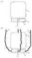
도 1 은, 본 발명의 일 실시형태에 관한 세포 이식용 기구의 담체를 나타내는 도면으로서, 도 1 의 (A) 는 평면도를 나타내고, 도 1 의 (B) 는 정면도를 나타낸다.
도 2 는 도 1 에 개시한 담체 상에 세포를 탑재한 상태를 나타내는 정면도로서, 도 2 의 (A) 는 선 형상 부재를 담체의 관통 구멍에 삽입 통과시키기 전 상태를 나타내는 정면도이고, 도 2 의 (B) 는 선 형상 부재를 담체의 관통 구멍에 삽입 통과시킨 상태를 나타내는 정면도이다.
도 3 은, 도 2 의 (B) 에 개시한 담체에 압입 부재를 근접시킨 상태를 나타내는 정면도이다.
도 4 는, 선 형상 부위에 압입 부재의 아암부를 걸어맞춘 상태를 나타내는 정면도이다.
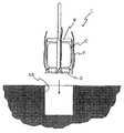
도 5 는, 도 4 에 개시한 세포 이식용 기구를 세포 결손부에 근접시킨 상태를 나타내는 일부 단면도이다.
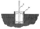
도 6 은, 세포 이식용 기구와 세포를 세포 결손부에 삽입한 상태를 나타내는 일부 단면도이다.
도 7 은, 담체의 관통 구멍으로부터 선 형상 부재를 빼낸 상태를 나타내는 일부 단면도이다.
도 8 은, 담체의 관통 구멍으로부터 압입 부재를 빼낸 상태를 나타내는 일부 단면도이다.
도 9 는, 본 발명의 제 2 실시형태에 관한 세포 이식용 기구를 나타내는 일부 단면도이다.
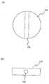
도 10 은, 본 발명의 제 3 실시형태에 관한 세포 이식용 기구의 압입 부재를 나타내는 정면도이다.
도 11 은, 본 발명의 제 4 실시형태에 관한 세포 이식용 기구의 담체를 나타내고, 도 11 의 (A) 는 평면도를 나타내며, 도 11 의 (B) 는 정면도를 나타낸다.
도 12 는, 본 발명의 제 5 실시형태에 관한 세포 이식용 기구의 담체를 나타내고, 도 12 의 (A) 는 평면도를 나타내며, 도 12 의 (B) 는 정면도를 나타낸다.
도 13 은, 본 발명의 제 6 실시형태에 관한 세포 이식용 기구의 담체를 나타내고, 도 13 의 (A) 는 평면도를 나타내며, 도 13 의 (B) 는 정면도를 나타낸다.BRIEF DESCRIPTION OF DRAWINGS FIG. 1 is a view showing a carrier for a cell implantation apparatus according to an embodiment of the present invention. FIG. 1 (A) is a plan view and FIG. 1 (B) is a front view.
Fig. 2 is a front view showing a state where cells are mounted on the carrier shown in Fig. 1, Fig. 2 (A) is a front view showing a state before the linear member is inserted into the through hole of the carrier, (B) is a front view showing a state in which the linear member is inserted into the through hole of the carrier.
Fig. 3 is a front view showing a state in which the press-in member is brought into close contact with the carrier shown in Fig. 2 (B).
4 is a front view showing a state in which the arm portion of the press-in member is engaged with the linear portion.
FIG. 5 is a partial cross-sectional view showing a state in which the cell implantation apparatus disclosed in FIG. 4 is brought close to a cell defect portion.
6 is a partial cross-sectional view showing a state in which a device for cell transplantation and cells are inserted into a cell defect portion.
7 is a partial cross-sectional view showing a state in which the linear member is pulled out from the through hole of the carrier.
8 is a partial cross-sectional view showing a state in which the press-in member is pulled out from the through hole of the carrier.
FIG. 9 is a partial cross-sectional view showing a cell implanting apparatus according to a second embodiment of the present invention. FIG.
10 is a front view showing a press-fitting member of a cell implantation apparatus according to a third embodiment of the present invention.
Fig. 11 shows a carrier for a cell implantation apparatus according to a fourth embodiment of the present invention. Fig. 11 (A) shows a plan view and Fig. 11 (B) shows a front view.
Fig. 12 shows a carrier for a cell implantation device according to a fifth embodiment of the present invention. Fig. 12 (A) shows a plan view and Fig. 12 (B) shows a front view.
Fig. 13 shows a carrier for a cell implantation apparatus according to a sixth embodiment of the present invention. Fig. 13 (A) shows a plan view and Fig. 13 (B) shows a front view.
발명을 실시하기 위한 최선의 형태BEST MODE FOR CARRYING OUT THE INVENTION
이하, 본 발명을 상세하게 설명한다. 본 발명의 범위는 이들 설명에 구속되지 않으며, 이하의 예시 이외에 대해서도, 본 발명의 취지를 저해하지 않는 범위에서 적절히 변경하여 실시할 수 있다.Hereinafter, the present invention will be described in detail. The scope of the present invention is not limited to these descriptions, and other than the following examples may be appropriately modified and practiced without departing from the spirit of the present invention.
또한, 본 명세서에 있어서 인용된 모든 간행물, 예를 들어 선행 기술 문헌, 및 공개 공보, 특허 공보 그 밖의 참조 문헌은, 참조로서 본 명세서에 도입된다.In addition, all publications cited herein, such as prior art documents, and published publications, patent publications, and other references, are incorporated herein by reference.
다음으로, 본원 발명의 일 실시형태에 대하여 도면을 참조하면서 설명한다.Next, an embodiment of the present invention will be described with reference to the drawings.
전체 개요Overview
도 3 에 나타내는 바와 같이, 본 실시형태에 관한 세포 이식용 기구 (1) 는, 이식용 세포 (C : 예를 들어, 세포 플러그) 를 담지하는 판 형상의 담체 (3) 와, 이 담체 (3) 의 측면부에 형성된 관통 구멍 (5) 에 삽입 통과되는 선 형상 부재 (7) 와, 관통 구멍 (5) 의 출구 근방에서 선 형상 부재와 걸어맞춰지는 압입 부재 (9) 로 구성되어 있다.3, the
담체carrier
먼저, 담체 (3) 에 대하여 설명한다. 도 1 에 나타내는 바와 같이, 본 실시형태에서는 담체 (3) 는 원판 형상의 형태를 하고 있으며, 재질은 생체 적합성 재료, 생체 분해성 재료 또는 생체 흡수성 재료이다. 이 담체 (3) 는 이식용 세포 (C) 를 담지하기 위한 것으로서, 표면이 평탄하게 되어 있다. 또, 담체 (3) 의 측면부에는 2 개의 관통 구멍 (5) 이 형성되어 있어, 결과적으로 측면부에 4 개의 출구 구멍이 형성되어 있다. 이 관통 구멍 (5) 은 후술하는 선 형상 부재 (7) 를 삽입 통과시키기 위한 것이다.First, the
또한, 담체 (3) 의 형상은 원판 형상으로 한정되는 것이 아니고, 직사각형판 형상이나 그 밖의 다각형판 형상이어도 된다. 또, 재질은 시술 후에 생체 내에서 분해되도록 트리 인산 칼슘을 채용하고 있는데, 본 발명은 이것에 한정되는 것이 아니고, 생체 내에서 분해 또는 흡수되는 다른 재료나 물질을 사용할 수도 있으며, 경우에 따라서는 분해되지 않는 재질을 사용해도 된다. 그 밖의 생체 적합성 재료, 생체 분해성 재료 또는 생체 흡수성 재료는, 당업자가 임의로 선택할 수 있다.The shape of the
본 실시형태에서는 2 개의 관통 구멍 (5) 이, 담체의 중심부 (원의 중심 부근) 를 통과하여 서로 직교하도록 형성되어 있다. 또, 본 실시형태에서는, 2 개의 관통 구멍 (5) 은 모두 담체의 두께 방향의 거의 중간 부근에 형성되어 있기 때문에, 담체 (3) 의 중심 부근에서 서로 교차되고 있다. 또한, 관통 구멍 (5) 의 수는 2 개로 한정되는 것이 아니며, 1 개여도 되고 3 개 이상이어도 된다. 또, 반드시 중심을 통과할 필요는 없으며, 중심에서 벗어난 위치에서 관통하도록 해도 된다.In the present embodiment, two through
선 형상 부재Linear member
다음으로, 선 형상 부재 (7) 에 대하여 설명한다. 도 2 에 나타내는 바와 같이, 선 형상 부재 (7) 는 담체 (3) 의 관통 구멍 (5) 에 삽입 통과되어, 담체 (3) 를 지지하기 위한 것이다. 선 형상 부재 (7) 에 사용되는 재료는 여러 가지를 생각할 수 있는데, 본 실시형태에서는 나일론실이 사용되고 있다. 나일론실 이외에는, 금속 와이어나 천연 섬유로 이루어지는 실 등을 사용해도 되며, 한정되는 것은 아니다. 또, 선 형상 부재 (7) 의 굵기는 최대로, 담체 (3) 의 관통 구멍 (5) 을 통과하는 굵기이면 되고, 그보다 가는 것이어도 된다. 또한, 도 2 에서는, 선 형상 부재는 일부 밖에 도시되어 있지 않지만, 실제로는 상방을 향해 길게 이어져 있다.Next, the
압입 부재The press-
다음으로, 압입 부재 (9) 에 대하여 설명한다. 압입 부재 (9) 는, 담체 (3) 그리고 선 형상 부재 (7) 와 협동하여, 담체 (3) 상에 탑재되는 세포 (C) 를 세포 결손부 (이식부) 에 삽입하기 위한 것이다. 도 3 에 나타내는 바와 같이, 압입 부재 (9) 는, 선 형상 부재 (7) 와 걸어맞춰지는 아암부 (9a) 와, 이 아암부 (9a) 를 지지하는 압입 부재 본체 (9b) 와, 압입 부재 본체 (9b) 에 연결되는 막대 형상 부재 (9c) 를 구비하고 있다. 아암부 (9a) 의 선단 (도면에서는 하단) 은 선 형상 부재 (7) 를 사이에 끼워 넣는 듯한 형상, 예를 들어 V 자형으로 분기되어 있다.Next, the press-in
본 실시형태에 관한 압입 부재 본체 (9b) 는 원판 형상의 부재로서, 이 압입 부재 본체 (9b) 의 외주면에 아암부 (9a) 가 연결되어 있다. 당해 실시형태에서는 4 개의 아암부 (9a) 가 형성되어 있으며, 압입 부재 본체 (9b) 의 외주면에 대략 90 ˚ 의 등각도 간격으로 배치되어 있다. 또, 압입 부재 본체 (9b) 의 직경은 세포 (C) 의 외경보다 약간 크기 때문에, 압입 부재 (9) 를 세포 (C) 에 근접시킨 경우에도 세포 (C) 의 외주면에 압입 부재 (9) 의 아암부 (9a) 가 접촉되지 않거나, 혹은 접촉한 경우에도 세포 (C) 의 형태가 아암부 (9a) 의 외력에 의해 변형 또는 손상되지 않는다. 또한, 세포 (C) 를 세포 결손부에 삽입할 때에, 아암부 (9a) 는 세포 (C) 와 세포 결손부 내벽 사이에 개삽 (介揷) 되는 것이므로, 두께는 가능한 한 얇은 것이 바람직하다.The press-fitting member
또, 압입 부재 (9) 의 막대 형상 부재 (9c) 에는, 상기 선 형상 부재 (7) 를 감아 고정시킬 수 있도록 하기 위한 선 형상 부재 감기 수단 (9d) 을 장비하도록 해도 된다. 이 선 형상 부재 감기 수단 (9d) 은, 막대 형상 부재 (9c) 의 표면으로부터 대략 V 자 형상으로 돌출되는 부재로서, 막대 형상 부재 (9c) 와의 간극에 선 형상 부재 (7) 를 감음으로써, 선 형상 부재 (7) 가 느슨해지지 않도록 할 수 있다. 단, 이 선 형상 부재 감기 수단 (9d) 은 본 발명에 필수적인 것은 아니다.The bar-
세포cell
본 발명에 있어서 사용되는 대상이 되는 세포는, 간세포 (ES 세포, 제대혈 유래 세포, 미분화 간엽계 간세포 등) 등의 미분화 세포 또는 그 분화형 세포이다. 골아세포, 연골 세포, 지방 세포는 미분화 간엽계 간세포로부터 용이하게 분화 유도가 가능하기 때문에, 이들 분화 유도된 세포 (관절 연골 세포, 골세포 등) 도 사용할 수 있다. 또, 성체 간엽계 간세포를 사용할 수도 있다.Cells to be used in the present invention are undifferentiated cells such as hepatocytes (ES cells, umbilical cord blood-derived cells, undifferentiated mesenchymal hepatocytes, etc.) or their differentiated cells. Since the osteoblast, chondrocyte, and adipocyte can be easily induced to differentiate from undifferentiated mesenchymal stem cells, these differentiation-induced cells (articular cartilage cells, bone cells, etc.) can also be used. In addition, adult mesenchymal stem cells may be used.
담체 (3) 상에 탑재되는 세포 (C) 는 입체적인 것이 바람직하다. 세포 (C) 를 입체적으로 구축하기 위해서는, 공지된 방법을 채용할 수 있다 (예를 들어, 일본 공개특허공보 2004-357694호 참조). 세포를 넣는 배양용 챔버를 임의의 형상으로 하고, 그 챔버 내에서 세포끼리의 응집 덩어리 (스페로이드) 를 배양함으로써, 그 형상에 대응하는 임의의 형상으로 입체적으로 구축된 세포, 즉 세포가 다수 모여 구성되는 세포 구조체를 얻을 수 있다.The cells (C) to be mounted on the carrier (3) are preferably three-dimensional. For constructing the cells C in a three-dimensional manner, a known method can be employed (see, for example, Japanese Laid-Open Patent Publication No. 2004-357694). The culture chamber into which the cells are put is made into an arbitrary shape, and an agglutination mass (spoloid) between the cells is cultured in the chamber, whereby cells formed in three dimensions in an arbitrary shape corresponding to the shape, A cell structure to be constituted can be obtained.
작용Action
다음으로, 본 실시형태에 관한 세포 이식용 기구의 작용에 대하여 설명한다. 먼저, 도 2 의 (A) 에 나타내는 바와 같이, 담체 (3) 의 표면에 원하는 이식용 세포 (C) 를 탑재한다. 다음으로, 도 2 의 (B) 에 나타내는 바와 같이, 담체 (3) 의 측면부에 형성된 2 개의 관통 구멍 (5) 에 2 개의 선 형상 부재 (7) 를 삽입 통과시킨다. 그리고, 각 선 형상 부재 (7) 의 4 개의 단부를 균등하게 집어 올린다. 이로써, 담체 (3) 는 대략 수평을 유지한 채로 들어 올려진다. 이 상태에서, 도 3 에 나타내는 바와 같이, 압입 부재 (9) 를 관통 구멍 (5) 의 4 개의 각 출구 구멍으로부터 나와 있는 선 형상 부재 (7) 에 근접시키고, 아암부 (9a) 의 V 자형의 선단부로 각 선 형상 부재 (7) 를 사이에 끼우도록 위치 결정한다. 계속해서, 압입 부재 (9) 를 더욱 하방으로 약간 압하하여 아암부 (9a) 를 선 형상 부재 (7) 에 걸어맞추면, 도 4 에 나타내는 바와 같이, 선 형상 부재 (7) 에 소정의 장력이 발생하여, 압입 부재 (9) 와 선 형상 부재 (7) 의 협동에 의해, 담체 (3) 를 통해 세포 (C) 를 확실하게 유지할 수 있게 된다. 이 때, 아암부 (9a) 의 길이는, 압입 부재 본체 (9b) 가 세포 (C) 의 상면에 접촉하지 않도록, 혹은 접촉해도 세포 (C) 의 형태가 변형되지 않을 정도로 충분한 길이가 확보되어 있다. 이 때문에, 세포 (C) 에는 불필요한 외력이 전혀 가해지지 않아, 세포 (C) 를 손상시키는 경우가 없다.Next, the operation of the cell implantation apparatus according to the present embodiment will be described. First, as shown in Fig. 2 (A), a desired cell (C) for grafting is mounted on the surface of the carrier (3). Next, as shown in Fig. 2 (B), the two
다음으로, 도 5 에 나타내는 바와 같이, 압입 부재 (9) 와 선 형상 부재 (7) 로 유지된 세포 (C) 를 세포 결손부 (13) 에 삽입한다. 구체적으로는, 미리 세포 결손부 (13) 에 세포 (C) 의 직경보다 약간 큰 직경을 갖는 구멍을 형성해 둔다. 그리고, 그 구멍에 세포 (C) 를 선 형상 부재 (7) 와 압입 부재 (9) 와 함께 삽입한다. 이 때, 세포 (C) 는 담체 (3) 를 통해 선 형상 부재 (7) 와 압입 부재 (9) 에 의해 확실하게 유지되어 있으므로, 압입 부재 (9) 를 조작함으로써, 도 6 에 나타내는 바와 같이, 세포 (C) 를 세포 결손부 (13) 의 최적의 깊이에 용이하게 위치 결정시킬 수 있다. 구체적으로는, 세포 (C) 의 표면이 세포 결손부 (13) 의 둘레의 표면보다 1 ㎜ 정도 돌출되는 위치에 배치하는 것이 바람직하다. 이렇게 함으로써, 세포 결손부 (13) 에 세포가 재생된 경우에 매끄러운 표면이 된다. 특히 본 실시형태에서는, 잘못하여 세포 (C) 를 세포 결손부의 깊은 위치에 지나치게 압입한 경우에도, 선 형상 부재 (7) 를 잡아 당김으로써 세포 (C) 를 꺼낼 수 있다.Next, as shown in Fig. 5, the cell C held by the press-in
세포 (C) 의 최적의 위치 결정이 완료되면, 도 7 에 나타내는 바와 같이, 선 형상 부재 (7) 를 담체 (3) 의 관통 구멍 (5) 으로부터 빼낸다. 구체적으로는, 각 선 형상 부재 (7) 의 일단을 잡아 당김으로써, 선 형상 부재 (7) 가 용이하게 빼내진다. 이 때, 지나치게 성급하게 빼내려고 하면 담체 (3) 도 동시에 빼내져 버리므로, 천천히 빼내도록 한다. 다음으로, 도 8 에 나타내는 바와 같이, 압입 부재 (9) 를 빼낸다. 이러한 일련의 작업에 의해, 세포 (C) 는 세포 결손부에 최적으로 위치 결정된다. 또한, 도 8 에서는 세포 (C) 와 세포 결손부의 내벽 사이에 간극이 도시되어 있는데, 이는 설명의 편의를 위한 간극으로서, 실제로는 간극은 거의 없는 상태로 세포 (C) 가 세포 결손부에 삽입되어 있다.7, the
제 2 실시형태Second Embodiment
다음으로, 본 발명의 제 2 실시형태에 대하여 설명한다. 도 9 에 나타내는 바와 같이, 당해 실시형태는, 압입 부재의 구조가 제 1 실시형태와 상이하며, 그 밖의 부분은 제 1 실시형태와 동일하다. 이 실시형태의 압입 부재 (9) 는, 세포 결손부의 주위 표면에 접촉하는 스토퍼 부재 (9e) 를 구비하고 있다는 점이 특징이다. 이 스토퍼 부재 (9e) 는, 아암부 (9a) 의 상단부를 덮도록 고정된 관 형상의 부재이다. 그리고, 스토퍼 부재 (9e) 의 위치는, 스토퍼 부재 (9e) 의 하단이 세포 결손부의 둘레 표면에 접촉했을 때에, 세포 (C) 가 올바르게 위치 결정되도록 설정되어 있다.Next, a second embodiment of the present invention will be described. As shown in Fig. 9, this embodiment differs from the first embodiment in the structure of the press-in member, and the other parts are the same as those of the first embodiment. The push-in
이와 같이, 아암부 (9a) 의 외측에 스토퍼 부재 (9e) 를 형성함으로써, 세포를 지나치게 압입한다는 문제가 해소된다. 이 때문에, 시술자는 깊이를 신경쓰지 않고 세포 (C) 의 이식 작업을 실시할 수 있다. 또한, 스토퍼 부재 (9e) 의 구조는 일례이며, 이것에 한정되는 것은 아니다. 즉, 관 형상의 부재가 아니라 아암 형상의 부재를 복수 형성해도 되며, 혹은 아암부의 상단에 돌기와 같은 것을 형성하도록 해도 된다.By forming the
제 3 실시형태Third Embodiment
다음으로, 제 3 실시형태에 대하여 설명한다 (도 10). 당해 실시형태도 압입 부재의 구조에 특징을 갖고 있으며, 그 밖의 부분은 제 1 실시형태와 동일하다. 본 실시형태의 압입 부재 (39) 는, 아암부 (39a) 의 선단이 V 자형이 아니라 원형이며, 그 중심 영역에 구멍 (39f) 이 형성되어 있다. 이와 같이 아암부 (39a) 의 선단에 구멍 (39f) 을 형성하고, 이 구멍 (39f) 에 선 형상 부재를 통과시킴으로써, 선 형상 부재의 장력이 느슨해진 경우에도 선 형상 부재가 아암부 (39a) 로부터 벗어나는 경우가 없다.Next, a third embodiment will be described (Fig. 10). This embodiment is also characterized by the structure of the press-in member, and the other parts are the same as in the first embodiment. The push-in
제 4 실시형태Fourth Embodiment
다음으로, 본 발명의 제 4 실시형태에 대하여 설명한다 (도 11). 당해 실시형태는 담체의 구조가 제 1 실시형태와 상이하며, 그 밖의 부분에 대해서는 제 1 실시형태와 동일하다. 이 실시형태의 담체 (33) 는, 2 개의 관통 구멍 (35) 의 위치 관계에 특징을 갖는다. 구체적으로는, 도 11 에 나타내는 바와 같이, 각 관통 구멍 (35) 이 담체 (33) 의 두께 방향으로 서로 어긋나 형성되어 있다. 이는, 각 관통 구멍 (35) 이 담체 (33) 의 중심부에서 직접 교차되지 않도록 하기 위함이다. 이와 같이 하는 것은, 서로 직교하는 관통 구멍 (35) 에 선 형상 부재를 삽입 통과시키는 경우에, 일방의 선 형상 부재가 타방의 선 형상 부재의 삽입 통과에 장해가 되지 않도록 하기 위함이다. 즉, 각 관통 구멍 (35) 이 서로 독립되어 있으면, 2 개의 선 형상 부재는 서로 만나지 않아, 용이하게 관통 구멍 (35) 에 삽입 통과시킬 수 있다.Next, a fourth embodiment of the present invention will be described (Fig. 11). This embodiment differs from the first embodiment in the structure of the carrier, and the other portions are the same as in the first embodiment. The
제 5 실시형태Fifth Embodiment
다음으로, 제 5 실시형태에 대하여 설명한다 (도 12). 당해 실시형태도 담체의 구조가 제 1 실시형태와 상이하며, 그 밖의 부분에 대해서는 제 1 실시형태와 동일하다. 이 실시형태의 담체 (43) 도, 2 개의 관통 구멍 (45) 의 위치 관계에 특징을 갖는다. 구체적으로는, 도 12 에 나타내는 바와 같이, 각 관통 구멍 (45) 이 담체 (43) 의 중심을 통과하지 않고, 담체 (43) 의 외주에 대하여 현 (弦) 을 형성하는 위치에 형성되어 있다. 특히, 본 실시형태에서는 2 개의 관통 구멍 (45) 은 서로 평행하게 형성되어 있다. 이러한 구성으로 함으로써, 제 4 실시형태에서 설명한 것과 동일하게, 2 개의 선 형상 부재는 서로 만나는 경우가 없어서, 용이하게 관통 구멍 (45) 에 삽입 통과시킬 수 있다.Next, a fifth embodiment will be described (Fig. 12). In this embodiment, the structure of the carrier is different from that of the first embodiment, and the other parts are the same as those of the first embodiment. The
제 6 실시형태Sixth Embodiment
다음으로, 제 6 실시형태에 대하여 설명한다 (도 13). 당해 실시형태도 담체의 구조가 제 1 실시형태와 상이하며, 그 밖의 부분에 대해서는 제 1 실시형태와 동일하다. 이 실시형태의 담체 (53) 는, 관통 구멍 (55) 의 수가 1 개라는 점에 특징을 갖고 있다. 구체적으로는, 도 13 에 나타내는 바와 같이, 관통 구멍 (55) 이 담체 (53) 의 중심을 통과하도록 형성되며, 이 관통 구멍 (55) 에 1 개의 선 형상 부재가 삽입 통과되도록 되어 있다. 이와 같이 관통 구멍 (55) 을 1 개로 줄임으로써, 담체 (53) 의 제조 비용을 저감시킬 수 있다. 단, 관통 구멍 (55) 을 1 개 밖에 형성하지 않는 경우, 아무런 궁리를 하지 않으면 세포가 담체 (53) 와 함께 뒤집혀 버린다. 이를 방지하기 위하여, 압입 부재의 아암부를 관통 구멍으로부터 벗어난 위치에도 형성할 필요가 있다.Next, a sixth embodiment will be described (Fig. 13). In this embodiment, the structure of the carrier is different from that of the first embodiment, and the other parts are the same as those of the first embodiment. The
본 발명은 담체에 이식용 세포를 탑재하고, 이 담체에 형성된 관통 구멍에 선 형상 부재를 삽입 통과시켜, 선 형상 부재와 걸어맞춰지는 압입 부재를 사용하므로, 이식용 세포에 직접 외력을 가하지 않고, 세포 결손부에 대한 이식용 세포의 위치 결정을 용이하게 할 수 있다.The present invention uses a push-in member for mounting a grafting cell on a carrier and passing a linear member through a through-hole formed in the carrier and engaging the linear member, so that no external force is applied directly to the grafting cell, It is possible to facilitate the positioning of the graft cell to the cell defect site.
산업상 이용가능성Industrial availability
본 발명은 세포 이식용 기기에 이용할 수 있다.The present invention can be applied to a device for cell transplantation.
1 : 세포 이식용 기구
3 : 담체
5 : 관통 구멍
7 : 선 형상 부재
9 : 압입 부재
9a : 아암 부재
9b : 압입 부재 본체
13 : 세포 결손부1: Device for cell transplantation
3: carrier
5: Through hole
7: Linear member
9:
9a: arm member
9b:
13: Cell deficient part
Claims (11)
Translated fromKorean상기 압입 부재는, 상기 선 형상 부재와 직접 걸어맞춰지는 아암부와, 이 아암부를 지지하는 압입 부재 본체를 구비하고, 상기 아암부는 상기 선 형상 부재와 걸어맞춰진 상태에서 상기 담체와 압입 부재 본체 사이에 소정의 간격을 형성하기 위한 길이를 갖고 있는 것을 특징으로 하는 세포 이식용 기구.The method according to claim 1,
Wherein the press-in member has an arm portion directly engaged with the linear member and a press-in member main body for supporting the arm portion, the arm portion being provided between the carrier and the press-in member main body in a state of being engaged with the linear member And a length for forming a predetermined gap.
상기 소정의 간격은 상기 담체 상에 탑재되는 이식용 세포의 높이보다 큰 것을 특징으로 하는 세포 이식용 기구.3. The method of claim 2,
Wherein the predetermined interval is greater than the height of the implantable cells mounted on the carrier.
상기 아암부의 선단은 V 자형인 것을 특징으로 하는 세포 이식용 기구.The method according to claim 2 or 3,
Wherein a distal end of the arm portion is V-shaped.
상기 아암부의 선단에는 상기 선 형상 부재를 통과시킬 수 있는 구멍이 형성되어 있는 것을 특징으로 하는 세포 이식용 기구.The method according to claim 2 or 3,
And a hole for allowing the linear member to pass therethrough is formed at a distal end of the arm portion.
상기 압입 부재에는, 이식하는 세포를 세포 결손부의 최적의 위치에 삽입한 경우에 상기 세포 결손부의 주위 표면과 접촉하는 스토퍼 부재가 형성되어 있는 것을 특징으로 하는 세포 이식용 기구.4. The method according to any one of claims 1 to 3,
Wherein the push-in member is provided with a stopper member which contacts the peripheral surface of the cell defect portion when the grafting cell is inserted at an optimal position of the cell defect portion.
상기 담체의 관통 구멍은 2 개 형성되어 있는 것을 특징으로 하는 세포 이식용 기구.4. The method according to any one of claims 1 to 3,
And two through-holes are formed in the carrier.
상기 각 관통 구멍은 서로 교차되지 않도록 상기 담체의 두께 방향의 위치가 상이한 것을 특징으로 하는 세포 이식용 기구.8. The method of claim 7,
Wherein the through holes are different in position in the thickness direction of the carrier so as not to intersect with each other.
상기 담체는 원판 형상으로 형성되며, 상기 관통 구멍은 상기 담체의 중심을 통과하는 것을 특징으로 하는 세포 이식용 기구.4. The method according to any one of claims 1 to 3,
Wherein the carrier is formed in a disk shape, and the through hole passes through the center of the carrier.
상기 각 관통 구멍의 각 출구 구멍은 상기 담체의 원주 방향으로 90 ˚ 간격으로 분포되어 있는 것을 특징으로 하는 세포 이식용 기구.8. The method of claim 7,
Wherein the outlet holes of the through holes are distributed at intervals of 90 占 in the circumferential direction of the carrier.
상기 담체는 트리 인산 칼슘으로 형성되어 있는 것을 특징으로 하는 세포 이식용 기구.4. The method according to any one of claims 1 to 3,
Wherein the carrier is formed of calcium triphosphate.
Applications Claiming Priority (1)
| Application Number | Priority Date | Filing Date | Title |
|---|---|---|---|
| PCT/JP2007/075343WO2009081503A1 (en) | 2007-12-21 | 2007-12-21 | Device for cell transplantation |
Publications (2)
| Publication Number | Publication Date |
|---|---|
| KR20110005231A KR20110005231A (en) | 2011-01-17 |
| KR101450943B1true KR101450943B1 (en) | 2014-10-21 |
Family
ID=40800820
Family Applications (1)
| Application Number | Title | Priority Date | Filing Date |
|---|---|---|---|
| KR1020107013701AExpired - Fee RelatedKR101450943B1 (en) | 2007-12-21 | 2007-12-21 | Device for cell transplantation |
Country Status (5)
| Country | Link |
|---|---|
| US (1) | US8246570B2 (en) |
| EP (1) | EP2233113A4 (en) |
| KR (1) | KR101450943B1 (en) |
| CN (1) | CN101969882B (en) |
| WO (1) | WO2009081503A1 (en) |
Families Citing this family (1)
| Publication number | Priority date | Publication date | Assignee | Title |
|---|---|---|---|---|
| JP5769334B2 (en)* | 2011-02-04 | 2015-08-26 | 国立大学法人佐賀大学 | Transplant guide and transplant device |
Citations (3)
| Publication number | Priority date | Publication date | Assignee | Title |
|---|---|---|---|---|
| JP2002537896A (en) | 1999-03-01 | 2002-11-12 | ラッシュ−プレズビテリアン−セント ルークス メディカル センター | In vitro production of implantable cartilage tissue |
| JP2003304866A (en) | 2002-04-17 | 2003-10-28 | National Institute Of Advanced Industrial & Technology | Control of cell differentiation by three-dimensional aggregate formation |
| JP2007075632A (en) | 1996-02-19 | 2007-03-29 | Warsaw Orthopaedic Inc | Spinal fusion implant, and tool for insertion and revision |
Family Cites Families (16)
| Publication number | Priority date | Publication date | Assignee | Title |
|---|---|---|---|---|
| US3101713A (en)* | 1961-02-23 | 1963-08-27 | Johnson & Johnson | Tampon applicator |
| US4276881A (en)* | 1979-10-22 | 1981-07-07 | Kimberly-Clark Corporation | Compact tampon applicator |
| JPH03106365A (en)* | 1989-09-20 | 1991-05-02 | Kao Corp | tampon |
| US5403348A (en)* | 1993-05-14 | 1995-04-04 | Bonutti; Peter M. | Suture anchor |
| US5545178A (en)* | 1994-04-29 | 1996-08-13 | Kensey Nash Corporation | System for closing a percutaneous puncture formed by a trocar to prevent tissue at the puncture from herniating |
| US5531759A (en)* | 1994-04-29 | 1996-07-02 | Kensey Nash Corporation | System for closing a percutaneous puncture formed by a trocar to prevent tissue at the puncture from herniating |
| ES2236792T3 (en) | 1995-03-27 | 2005-07-16 | Sdgi Holdings, Inc. | IMPLANTS OF SPINAL FUSION AND INSTRUMENTS FOR INSERTION AND REVIEW. |
| WO2000009179A2 (en)* | 1998-08-14 | 2000-02-24 | Verigen Transplantation Service International (Vtsi) Ag | Methods, instruments and materials for chondrocyte cell transplantation |
| DE69931018T2 (en)* | 1998-12-30 | 2006-11-23 | Ethicon, Inc. | Thread belay device |
| US6733505B2 (en)* | 2000-04-26 | 2004-05-11 | Sdgi Holdings, Inc. | Apparatus and method for loading a prosthetic nucleus into a deployment cannula to replace the nucleus pulposus of an intervertebral disc |
| US6425919B1 (en)* | 1999-08-18 | 2002-07-30 | Intrinsic Orthopedics, Inc. | Devices and methods of vertebral disc augmentation |
| US7004970B2 (en)* | 1999-10-20 | 2006-02-28 | Anulex Technologies, Inc. | Methods and devices for spinal disc annulus reconstruction and repair |
| US6712822B2 (en)* | 2001-10-01 | 2004-03-30 | Scandius Biomedical, Inc. | Apparatus and method for the repair of articular cartilage defects |
| JP4122280B2 (en) | 2003-05-15 | 2008-07-23 | 幸英 岩本 | Manufacturing method of tissue plug |
| CN100571791C (en) | 2003-07-31 | 2009-12-23 | 岩本幸英 | Method for manufacturing artificial joint |
| GB0325141D0 (en) | 2003-10-28 | 2003-12-03 | Xiros Plc | Repair of damaged tissue on a bone site |
- 2007
- 2007-12-21KRKR1020107013701Apatent/KR101450943B1/ennot_activeExpired - Fee Related
- 2007-12-21WOPCT/JP2007/075343patent/WO2009081503A1/enactiveApplication Filing
- 2007-12-21EPEP07860540Apatent/EP2233113A4/ennot_activeWithdrawn
- 2007-12-21CNCN200780102002.XApatent/CN101969882B/ennot_activeExpired - Fee Related
- 2007-12-21USUS12/809,104patent/US8246570B2/ennot_activeExpired - Fee Related
Patent Citations (3)
| Publication number | Priority date | Publication date | Assignee | Title |
|---|---|---|---|---|
| JP2007075632A (en) | 1996-02-19 | 2007-03-29 | Warsaw Orthopaedic Inc | Spinal fusion implant, and tool for insertion and revision |
| JP2002537896A (en) | 1999-03-01 | 2002-11-12 | ラッシュ−プレズビテリアン−セント ルークス メディカル センター | In vitro production of implantable cartilage tissue |
| JP2003304866A (en) | 2002-04-17 | 2003-10-28 | National Institute Of Advanced Industrial & Technology | Control of cell differentiation by three-dimensional aggregate formation |
Also Published As
| Publication number | Publication date |
|---|---|
| US20110106005A1 (en) | 2011-05-05 |
| CN101969882A (en) | 2011-02-09 |
| EP2233113A4 (en) | 2013-01-02 |
| KR20110005231A (en) | 2011-01-17 |
| WO2009081503A1 (en) | 2009-07-02 |
| EP2233113A1 (en) | 2010-09-29 |
| US8246570B2 (en) | 2012-08-21 |
| CN101969882B (en) | 2013-11-06 |
Similar Documents
| Publication | Publication Date | Title |
|---|---|---|
| DE19841337C1 (en) | Intracellular manipulation of biological cell contents, assisting injection or removal of substances or cell components | |
| WO2011140497A3 (en) | Method and apparatus for tissue grafting and copying | |
| ATE519447T1 (en) | CONSTRUCTION WITH HYDROXYLATED SURFACE | |
| Yang et al. | Performance of different three-dimensional scaffolds for in vivo endochondral bone generation | |
| CA2503848A1 (en) | Instrumentation, methods, and features for use in implanting an artificial intervertebral disc | |
| JP2010510026A5 (en) | ||
| WO2006133186A3 (en) | A system, including method and apparatus for percutaneous endovascular treatment of functional mitral valve insufficiency | |
| TW200635566A (en) | Structures for permanent occlusion of a hollow anatomical structure | |
| JP2006513007A (en) | Unit for treating disc degeneration | |
| SG152283A1 (en) | Test magazine and method for processing the same | |
| JP2006500105A5 (en) | ||
| KR101450943B1 (en) | Device for cell transplantation | |
| WO2013073672A1 (en) | Device for manufacturing supporting body for cell structure manufacture | |
| WO2010029295A3 (en) | Medical device | |
| CN108136076A (en) | Cell leaflet material through culture | |
| DE60032508D1 (en) | PROCESS FOR THE REPRODUCTION OF NATURAL KILLER CELLS | |
| EP2349368A4 (en) | Jawbone prosthesis and manufacturing method thereof | |
| ES2942844T3 (en) | Transplant guide piece and transplant tool | |
| JP5412688B2 (en) | Method for producing cell-free biological tissue for reactivation and apparatus for carrying out the method | |
| JP4580904B2 (en) | Cell transplantation instrument | |
| KR20190090806A (en) | Vascular grafts, methods for making the same, and articles comprising the same | |
| KR100721603B1 (en) | Implant Separator | |
| MXPA03009312A (en) | Method for autologous transplantation. | |
| US20190142593A1 (en) | Nanofiber coating to improve biological and mechanical performance of joint prosthesis | |
| KR102612599B1 (en) | Nerve conduit for promoting amputated nerve regeneration using electric fields |
Legal Events
| Date | Code | Title | Description |
|---|---|---|---|
| PA0105 | International application | St.27 status event code:A-0-1-A10-A15-nap-PA0105 | |
| T11-X000 | Administrative time limit extension requested | St.27 status event code:U-3-3-T10-T11-oth-X000 | |
| T11-X000 | Administrative time limit extension requested | St.27 status event code:U-3-3-T10-T11-oth-X000 | |
| T11-X000 | Administrative time limit extension requested | St.27 status event code:U-3-3-T10-T11-oth-X000 | |
| P11-X000 | Amendment of application requested | St.27 status event code:A-2-2-P10-P11-nap-X000 | |
| P13-X000 | Application amended | St.27 status event code:A-2-2-P10-P13-nap-X000 | |
| PG1501 | Laying open of application | St.27 status event code:A-1-1-Q10-Q12-nap-PG1501 | |
| R18-X000 | Changes to party contact information recorded | St.27 status event code:A-3-3-R10-R18-oth-X000 | |
| A201 | Request for examination | ||
| P11-X000 | Amendment of application requested | St.27 status event code:A-2-2-P10-P11-nap-X000 | |
| P13-X000 | Application amended | St.27 status event code:A-2-2-P10-P13-nap-X000 | |
| PA0201 | Request for examination | St.27 status event code:A-1-2-D10-D11-exm-PA0201 | |
| E902 | Notification of reason for refusal | ||
| PE0902 | Notice of grounds for rejection | St.27 status event code:A-1-2-D10-D21-exm-PE0902 | |
| T11-X000 | Administrative time limit extension requested | St.27 status event code:U-3-3-T10-T11-oth-X000 | |
| P11-X000 | Amendment of application requested | St.27 status event code:A-2-2-P10-P11-nap-X000 | |
| P13-X000 | Application amended | St.27 status event code:A-2-2-P10-P13-nap-X000 | |
| R18-X000 | Changes to party contact information recorded | St.27 status event code:A-3-3-R10-R18-oth-X000 | |
| E701 | Decision to grant or registration of patent right | ||
| PE0701 | Decision of registration | St.27 status event code:A-1-2-D10-D22-exm-PE0701 | |
| R18-X000 | Changes to party contact information recorded | St.27 status event code:A-3-3-R10-R18-oth-X000 | |
| GRNT | Written decision to grant | ||
| PR0701 | Registration of establishment | St.27 status event code:A-2-4-F10-F11-exm-PR0701 | |
| PR1002 | Payment of registration fee | St.27 status event code:A-2-2-U10-U12-oth-PR1002 Fee payment year number:1 | |
| PG1601 | Publication of registration | St.27 status event code:A-4-4-Q10-Q13-nap-PG1601 | |
| LAPS | Lapse due to unpaid annual fee | ||
| PC1903 | Unpaid annual fee | St.27 status event code:A-4-4-U10-U13-oth-PC1903 Not in force date:20171008 Payment event data comment text:Termination Category : DEFAULT_OF_REGISTRATION_FEE | |
| PC1903 | Unpaid annual fee | St.27 status event code:N-4-6-H10-H13-oth-PC1903 Ip right cessation event data comment text:Termination Category : DEFAULT_OF_REGISTRATION_FEE Not in force date:20171008 |