KR101450314B1 - Reducer of Electric Power Steering Apparatus - Google Patents
Reducer of Electric Power Steering ApparatusDownload PDFInfo
- Publication number
- KR101450314B1 KR101450314B1KR1020110130783AKR20110130783AKR101450314B1KR 101450314 B1KR101450314 B1KR 101450314B1KR 1020110130783 AKR1020110130783 AKR 1020110130783AKR 20110130783 AKR20110130783 AKR 20110130783AKR 101450314 B1KR101450314 B1KR 101450314B1
- Authority
- KR
- South Korea
- Prior art keywords
- worm
- shaft
- worm shaft
- coupled
- motor
- Prior art date
- Legal status (The legal status is an assumption and is not a legal conclusion. Google has not performed a legal analysis and makes no representation as to the accuracy of the status listed.)
- Active
Links
Images


Classifications
- B—PERFORMING OPERATIONS; TRANSPORTING
- B62—LAND VEHICLES FOR TRAVELLING OTHERWISE THAN ON RAILS
- B62D—MOTOR VEHICLES; TRAILERS
- B62D5/00—Power-assisted or power-driven steering
- B62D5/04—Power-assisted or power-driven steering electrical, e.g. using an electric servo-motor connected to, or forming part of, the steering gear
- B62D5/0421—Electric motor acting on or near steering gear
- B—PERFORMING OPERATIONS; TRANSPORTING
- B62—LAND VEHICLES FOR TRAVELLING OTHERWISE THAN ON RAILS
- B62D—MOTOR VEHICLES; TRAILERS
- B62D3/00—Steering gears
- B62D3/02—Steering gears mechanical
- B62D3/04—Steering gears mechanical of worm type
- F—MECHANICAL ENGINEERING; LIGHTING; HEATING; WEAPONS; BLASTING
- F16—ENGINEERING ELEMENTS AND UNITS; GENERAL MEASURES FOR PRODUCING AND MAINTAINING EFFECTIVE FUNCTIONING OF MACHINES OR INSTALLATIONS; THERMAL INSULATION IN GENERAL
- F16H—GEARING
- F16H55/00—Elements with teeth or friction surfaces for conveying motion; Worms, pulleys or sheaves for gearing mechanisms
- F16H55/02—Toothed members; Worms
- F16H55/22—Toothed members; Worms for transmissions with crossing shafts, especially worms, worm-gears
- F16H55/24—Special devices for taking up backlash
- B—PERFORMING OPERATIONS; TRANSPORTING
- B60—VEHICLES IN GENERAL
- B60Y—INDEXING SCHEME RELATING TO ASPECTS CROSS-CUTTING VEHICLE TECHNOLOGY
- B60Y2306/00—Other features of vehicle sub-units
- B60Y2306/09—Reducing noise
Landscapes
- Engineering & Computer Science (AREA)
- Mechanical Engineering (AREA)
- Chemical & Material Sciences (AREA)
- Combustion & Propulsion (AREA)
- Transportation (AREA)
- General Engineering & Computer Science (AREA)
- Power Steering Mechanism (AREA)
Abstract
Translated fromKorean
Description
Translated fromKorean본 발명은 전동식 동력 보조 조향장치의 감속기에 관한 것이다. 더욱 상세하게는 전동식 동력 보조 조향장치의 감속기에 있어서, 웜과 웜휠의 마모에 의한 유격을 방지하고 노면으로부터 전달되는 충격음과 백래쉬에 의한 래틀 노이즈를 줄이며, 회전 토크의 변화에 따른 유격변화량을 최소화함으로써 운전자의 조향휠 조작력을 정확하게 보조할 수 있는 전동식 동력 보조 조향장치의 감속기에 관한 것이다.The present invention relates to a speed reducer of an electric power assisted steering apparatus. More particularly, the present invention relates to a decelerator of an electric power assist steering apparatus, which prevents a worm caused by abrasion of a worm and a worm wheel, reduces rattle noise caused by impact noise transmitted from a road surface and backlash, To a speed reducer of an electric power assisted steering apparatus capable of accurately assisting a steering wheel operating force of a driver.
도 1은 종래 전동식 동력 보조 조향장치의 구성도로서, 도 1에서 도시된 바와 같이 전동식 동력 보조 조향장치(100)는 조향휠(102)로부터 양측 바퀴(126)까지 이어지는 조향 계통(130) 및 조향 계통(130)에 조향 보조 동력을 제공하는 보조 동력 기구(140)를 포함하여 구성된다.1, the electric power
조향 계통(130)은 일측이 조향휠(102)에 연결되어 조향휠(102)과 함께 회전하고 타측은 한 쌍의 유니버설 조인트(104)를 매개로 피니언축(108)에 연결되는 조향축(106)을 포함하여 구성된다. 또한, 피니언축(108)은 랙-피니언 기구부(110)를 통해 랙바(112)에 연결되고, 랙바(112)의 양단은 타이로드(122)와 너클암(124)을 통해 차량의 바퀴(126)에 연결된다.The
보조 동력 기구(140)는 운전자가 조향휠(102)에 가하는 토크를 감지하고 감지된 토크에 비례하는 전기 신호를 출력하는 토크 센서(142), 토크 센서(142)로부터 전해지는 전기신호에 기초하여 제어 신호를 발생하는 전자 제어 장치(144), 전자 제어 장치(144)로부터 전해지는 제어 신호에 기초하여 보조 동력을 발생시키는 모터(146) 및 모터(146)에서 발생한 보조 동력을 조향축(106)에 전달하기 위하여 웜(152) 및 웜휠(156)을 구비한 감속기(150)를 포함하여 구성된다.The
따라서, 전동식 동력 보조 조향장치는 조향휠(102)의 회전에 의해 발생한 토크가 랙-피니언 기구부(110)를 거쳐서 랙바(112)에 전달되고, 발생된 토크에 따라 모터(146)에서 발생한 보조 동력이 랙바(112)에 전달되도록 구성된다.Therefore, the electric power assist steering apparatus is configured such that the torque generated by the rotation of the
즉, 조향휠(102)의 회전에 의해 발생한 토크와 모터(146)에서 발생한 보조 동력이 합쳐져서 랙바(112)를 축 방향으로 운동하도록 하는 것이다.That is, the torque generated by the rotation of the
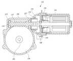
도 2는 종래 전동식 동력 보조 조향장치의 감속기를 나타내는 단면도로서, 도 2에서 도시된 바와 같이 감속기(150)는 웜(152)이 형성된 웜축(254)이 구비되고 웜축(254)의 양단에는 웜축베어링(257)이 각각 설치되어 웜축(254)을 지지하며, 웜축베어링(257)이 웜축(254)의 축방향으로 유격되는 것을 방지하기 위해 플러그 볼트(210)가 댐핑 커플러(240)와 웜축베어링(257) 사이에 체결되고, 플러그 볼트(210)는 플러그 너트(220)에 의해 고정된다.2, the
웜축(254)은 모터(146)와 댐핑 커플러(240)를 매개로 연결되어 모터(146)의 구동에 의해 웜축(254)이 회전하는 구조로 되어 있다.The
그리고 웜축(254) 상에 형성된 웜(152)과 치물림될 수 있도록 웜(152)의 외경 일측에는 웜휠(156)이 구비되며, 웜휠(156)은 운전자가 조작하는 조향휠(도 1의 102참조)의 회전력을 전달하는 조향축(106)에 장착되어 모터(146)의 구동에 의한 웜축(254)의 회전력이 조향축(106)에 전달되는 구조이다.A
기어 하우징(260)에는 웜(152), 웜휠(156) 등이 내주하고 기어 하우징(260)의 일측으로 웜축(254)에 구동력을 제공하는 모터(146)가 구비되며, 기어 하우징(260)과 모터(146)는 모터 커버(230)에 의해 볼트(250)로 결합된다.The
이와 같은 구조로 이루어진 전동식 동력 보조 조향장치의 감속기는 차량 운행조건에 따라 차량에 구비된 전자 제어 장치에 의해 모터의 구동을 제어하고, 모터의 구동에 의한 웜축의 회전력이 운전자가 조작하는 조향휠의 회전력에 부가하여 조향축에 전달됨으로써, 운전자의 조향 운전 상태를 부드럽고 안정적으로 유지할 수 있도록 한 것이다.The speed reducer of the electric power assist steering apparatus having the above structure controls the driving of the motor by the electronic control unit provided in the vehicle according to the driving condition of the vehicle, and the rotation of the worm shaft by the driving of the motor is controlled by the steering wheel And is transmitted to the steering shaft in addition to the rotational force, so that the steering operation state of the driver can be maintained smoothly and stably.
그런데, 종래 전동식 동력 보조 조향장치의 감속기는 웜축과 모터축의 결합부위에 제조상의 오차와 조립상의 오차가 누적되어 베어링의 걸림감이 발생되고 웜축의 회전 저항이 증대되는 문제점이 있었고, 또한 웜과 웜휠이 내구가 진행되면 마모에 의해 유격이 발생되고, 백래쉬로 인한 래틀 노이즈가 발생되는 문제점과, 노면으로부터 바퀴와 조향축을 통해 전달되는 충격으로 래틀 노이즈로 인해 운전자에게 조향휠 조작시 불쾌감을 일으키게 되는 문제점이 있었다.However, in the conventional reducer of the electric power assisted steering system, there is a problem that the manufacturing error and the assembling error are accumulated at the joint portion between the worm shaft and the motor shaft, and the rolling resistance of the worm shaft is increased, The rattling noise is generated by the backlash and the rattling noise transmitted from the road surface through the wheels and the steering shaft causes the driver to feel uncomfortable when operating the steering wheel .
그런데, 종래 전동식 동력 보조 조향장치의 감속기는 모터의 구동에 의해 회전하는 웜과 웜휠이 내구가 진행되면 마모에 의해 발생되는 유격으로 노이즈가 발생되는 문제점이 있었다.However, the conventional speed reducer of the electric power assisted steering system has a problem in that, when the worm and the worm wheel, which are rotated by the motor, are driven, noise is generated due to the clearance generated by the wear.
또한, 노면으로부터 바퀴와 조향축을 타고 전달되는 충격음과 웜과 웜휠의 백래쉬로 인한 노이즈가 발생되는 문제점이 있었다.In addition, there is a problem that noises are generated due to impact noise transmitted from the road surface on the wheels and the steering shaft, and backlash of the worm and the worm wheel.
따라서, 이와 같은 문제점들로 인해 운전자의 조향휠 조작력을 보조하는 조향 보조력을 정확하게 제공할 수 없게 되는 문제점도 있었다.
Accordingly, the steering assist force for assisting the steering wheel operating force of the driver can not be accurately provided due to such problems.
이에 본 발명은 전술한 문제점을 해결하기 위해 안출된 것으로, 전동식 동력 보조 조향장치의 감속기에 있어서, 웜과 웜휠의 마모에 의한 유격을 방지하고 노면으로부터 전달되는 충격음과 백래쉬에 의한 래틀 노이즈를 줄이며, 회전 토크의 변화에 따른 유격변화량을 최소화함으로써 운전자의 조향휠 조작력을 정확하게 보조하는 데에 그 목적이 있다.SUMMARY OF THE INVENTION Accordingly, the present invention has been made keeping in mind the above problems occurring in the prior art, and an object of the present invention is to provide a decelerator of an electric power assisted steering apparatus capable of preventing a worm caused by abrasion of a worm and a worm wheel, reducing impact noise transmitted from a road surface and rattle noise caused by backlash, The present invention has an object of accurately assisting the steering wheel operating force of the driver by minimizing the change amount of the clearance according to the change of the rotational torque.
이러한 목적을 달성하기 위하여, 본 발명의 일실시예는 웜축의 양단부 중 모터축 연결부의 단부에 축방향으로 결합되며 일측이 모터 플러그에 지지되어 상기 웜축의 축방향 하중과 회전을 지지하는 스러스트 베어링; 상기 스러스트 베어링의 타측과 상기 웜축의 웜 형성부 외측에 축방향으로 결합되어 상기 웜축이 축방향과 소정의 각로로 비틀리는 운동을 지지하는 피봇부재; 상기 웜축의 양단부 중 모터축 연결부의 반대쪽 단부에 결합되어 상기 웜축의 회전과 경방향 하중을 지지하는 웜축베어링을 포함하여 구성되는 것을 특징으로 하는 전동식 동력 보조 조향장치의 감속기를 제공한다.In order to achieve the above object, according to one embodiment of the present invention, there is provided a thrust bearing, which is axially coupled to an end portion of a motor shaft connection portion at both ends of a worm shaft and one side thereof is supported by a motor plug to support an axial load and rotation of the worm shaft. A pivot member coupled axially to the other side of the thrust bearing and to the outside of the worm forming portion of the worm shaft to support the worm axis twisting at a predetermined angle with the axial direction; And a worm shaft bearing coupled to an end of the worm shaft opposite to the motor shaft connecting portion to support the rotation and the radial load of the worm shaft.
본 발명에 의하면 전동식 동력 보조 조향장치의 감속기에 있어서, 웜과 웜휠의 마모에 의한 유격을 방지하고 노면으로부터 전달되는 충격음과 백래쉬에 의한 래틀 노이즈를 줄이며, 회전 토크의 변화에 따른 유격변화량을 최소화함으로써 운전자의 조향휠 조작력을 정확하게 보조할 수 있게 되는 효과가 있다.According to the present invention, in a speed reducer of an electric power assisted steering apparatus, it is possible to prevent a clearance caused by abrasion of a worm and a worm wheel, reduce rattle noise caused by impact noise transmitted from a road surface and backlash, The steering wheel operating force of the driver can be accurately assisted.
도 1은 종래 전동식 동력 보조 조향장치의 구성도;
도 2는 종래 전동식 동력 보조 조향장치의 감속기를 나타내는 단면도;
도 3은 본 발명의 일실시예에 의한 전동식 동력 보조 조향장치의 감속기를 나타내는 단면도이다.1 is a block diagram of a conventional electric power assist steering apparatus;
2 is a sectional view showing a speed reducer of a conventional electric power assist steering apparatus;
3 is a cross-sectional view illustrating a speed reducer of an electric power assisted steering apparatus according to an embodiment of the present invention.
이하, 본 발명의 일부 실시예들을 예시적인 도면을 통해 상세하게 설명한다. 각 도면의 구성요소들에 참조부호를 부가함에 있어서, 동일한 구성요소들에 대해서는 비록 다른 도면상에 표시되더라도 가능한 한 동일한 부호를 가지도록 하고 있음에 유의해야 한다. 또한, 본 발명을 설명함에 있어, 관련된 공지 구성 또는 기능에 대한 구체적인 설명이 본 발명의 요지를 흐릴 수 있다고 판단되는 경우에는 그 상세한 설명은 생략한다.Hereinafter, some embodiments of the present invention will be described in detail with reference to exemplary drawings. It should be noted that, in adding reference numerals to the constituent elements of the drawings, the same constituent elements are denoted by the same reference symbols as possible even if they are shown in different drawings. In the following description of the present invention, a detailed description of known functions and configurations incorporated herein will be omitted when it may make the subject matter of the present invention rather unclear.
또한, 본 발명의 구성 요소를 설명하는 데 있어서, 제 1, 제 2, A, B, (a), (b) 등의 용어를 사용할 수 있다. 이러한 용어는 그 구성 요소를 다른 구성 요소와 구별하기 위한 것일 뿐, 그 용어에 의해 해당 구성 요소의 본질이나 차례 또는 순서 등이 한정되지 않는다. 어떤 구성 요소가 다른 구성요소에 "연결", "결합" 또는 "접속"된다고 기재된 경우, 그 구성 요소는 그 다른 구성요소에 직접적으로 연결되거나 또는 접속될 수 있지만, 각 구성 요소 사이에 또 다른 구성 요소가 "연결", "결합" 또는 "접속"될 수도 있다고 이해되어야 할 것이다.In describing the components of the present invention, terms such as first, second, A, B, (a), and (b) may be used. These terms are intended to distinguish the constituent elements from other constituent elements, and the terms do not limit the nature, order or order of the constituent elements. When a component is described as being "connected", "coupled", or "connected" to another component, the component may be directly connected to or connected to the other component, It should be understood that an element may be "connected," "coupled," or "connected."
도 3은 본 발명의 일실시예에 의한 전동식 동력 보조 조향장치의 감속기를 나타내는 단면도이다.3 is a cross-sectional view illustrating a speed reducer of an electric power assisted steering apparatus according to an embodiment of the present invention.
도 3에 도시된 바와 같이 본 발명의 일실시예에 의한 전동식 동력 보조 조향장치의 감속기는, 웜축(254)이 축방향 또는 축방향과 소정의 각로로 비틀리는 하중 발생시 웜축(254)의 진동과 소음을 흡수하도록, 상기 웜축(254)의 양단부 중 모터축(146a) 연결부의 단부에 축방향으로 결합되며 일측이 플러그 볼트(210)에 지지되어 상기 웜축(254)의 축방향 하중과 회전을 지지하는 스러스트 베어링(305); 상기 스러스트 베어링(305)의 타측과 상기 웜축(254)의 웜 형성부 외측(254a)에 축방향으로 결합되어 상기 웜축(254)이 축방향과 소정의 각로로 비틀리는 운동을 지지하는 피봇부재(310); 상기 웜축(254)의 양단부 중 모터축(146a) 연결부의 반대쪽 단부에 결합되어 상기 웜축(254)의 회전시 경방향 하중을 지지하는 웜축베어링(257)을 포함하여 구성된다.3, the speed reducer of the electric power assisted steering apparatus according to an embodiment of the present invention is configured such that when the
모터축(146a)과 결합되는 부위의 웜축(254) 단부에는 웜축(254)의 축방향 하중과 회전을 지지하는 스러스트 베어링(305)과 웜축(254)의 피봇운동을 지지하는 피봇부재(310)가 결합되고, 이의 반대쪽 단부에는 웜축베어링(257)이 내륜과 외륜 사이에 볼이 결합되어 웜축(254)의 회전을 지지하게 되어 있다.A thrust bearing 305 for supporting the axial load and rotation of the
이러한 감속기는 모터(146)의 구동력에 의해 웜(152)과 웜휠(156)이 연동되면서 조향축(106)을 회전시켜 운전자의 조향력을 보조하게 되는데, 조향축(106)과 연동되는 웜휠(156)과 웜축(254)은 기어 하우징(260)에 내장되어 있다.The
스러스트 베어링(305)과 웜축베어링(257)은 기어 하우징(260)의 내측에 장착되며 웜축(254)의 양단에서 웜축(254)의 회전을 지지하며 웜축(254)의 회전 저항을 줄여주는데, 웜축(254)과 모터축(146a)이 결합되는 부위는 모터 보스(340)와 플러그 볼트(210)를 매개로 하는 축과 축의 연결부위여서, 제작 오차와 조립 오차가 누적되어 베어링의 걸림량이 커지게 되고, 이로 인해 웜축(254)의 회전 저항이 증대되게 된다.The thrust bearing 305 and the worm shaft bearing 257 are mounted inside the
또한, 노면으로부터 바퀴와 조향축(106)을 통해 전달되는 외력이 웜휠(156)로 전달될 때 축방향뿐만 아니라 웜휠(156)과 치합되는 웜축(254)이 축방향과 소정의 각도로 비틀리는 운동을 일으키게 된다.When the external force transmitted from the road surface through the
따라서, 웜휠(156)을 통해 전달되는 외력과, 웜(152)과 웜휠(156)의 작동으로 웜축(254)이 축방향 또는 축방향과 소정의 각로로 비틀리는 하중 전달시 이로 인해 발생되는 진동과 소음을 흡수할 수 있도록 웜축(254)의 양단부 중, 모터축(146a) 결합 부위에는 피봇부재(310), 스러스트 베어링(305), 플러그 볼트(210) 등이 결합되어 있다.Therefore, the external force transmitted through the
그리고, 모터축(146a) 결합부위의 반대쪽 웜축(254) 단부에 결합된 웜축베어링(257)은 웜축(254)의 회전을 지지하면서 웜휠(156)을 통해 들어오는 외력이나 웜(152)과 웜휠(156)의 작동시 발생되는 웜축(254)의 회전과 경방향 하중을 지지하게 된다.The worm shaft bearing 257 coupled to the end of the
스러스트 베어링(305)은 볼, 롤러, 니들 등이 회전 가능하게 결합되는 결합부재(301)와, 결합부재(301)의 양측에 결합되는 지지부재(303) 등으로 이루어지며, 웜축(254)의 양단부 중 모터축(146a) 연결부의 단부에 축방향으로 결합된다.The thrust bearing 305 is composed of a
스러스트 베어링(305)의 일측은 기어 하우징(260)에 고정되는 플러그 볼트(210)의 측면에 지지되고, 타측은 피봇부재(310)에 지지되며 웜축(254)에 결합된다.One side of the thrust bearing 305 is supported on the side of the
피봇부재(310)는 웜축(254)이 축방향과 소정의 각도로 비틀리는 운동을 지지할 수 있도록 스러스트 베어링(305)의 타측과 웜축(254)의 웜 형성부 외측(254a)에 축방향으로 결합되는데, 스러스트 베어링(305)과 결합되는 면은 평면으로 형성되고 웜축(254)과 결합되는 면은 곡면으로 형성되며, 피봇부재(310)에 지지되는 웜축(254)의 웜 형성부 외측면(254a)도 곡면으로 형성될 수 있다.The
따라서, 피봇부재(310)의 중심부에 삽입 결합된 웜축(254)의 단부를 기준으로 웜축(254)의 피봇운동이 가능하게 되는데, 이때 웜축(254)의 웜 형성부 외측면(254a)이 곡면으로 형성되어 있는 피봇부재(310)의 지지면(310a)에 지지되어 매끄럽게 운동할 수 있게 되어 있다.Therefore, the
또한, 웜축(254)의 웜 형성부 외측면(254a)과 피봇부재(310)의 지지면(310a)은 서로 대향되는 구면으로 형성될 수 있는데, 이 경우 웜축(254)의 웜 형성부 외측(254a)면과 피봇부재(310)의 지지면(310a)이 동일한 곡률반경을 갖는 구면으로 형성되어 웜축(254)의 피봇 운동을 보다 견고하게 지지할 수 있게 된다.The
이와 같은 피봇부재(310)는 웜축(254)이 피봇부재(310)의 중심부를 관통하여 결합되며 축방향의 힘을 받게 결합되는데, 반드시 이에 한정되는 것은 아니며 경우에 따라서는 피봇부재(310)의 외주면에 나사산을 형성하여 이와 치합되는 나사골이 형성된 기어하우징(260)과 나사 결합될 수도 있다.The
여기서, 피봇부재(310)는 스틸 재질로 형성되지만, 폴리 아세탈(POM), 폴리 아미드(PA), 폴리 카보네이트(PC), 폴리 이미드(PI), 폴리 부틸렌 테레프 탈레이트(PBT) 등과 같은 엔지니어링 플라스틱계열 재질로 형성될 수 있다.Here, the
한편, 웜축(254)의 양단부 중 모터축(146a) 연결부의 반대쪽 단부에는 기어 하우징(260)에 지지되어 웜축(254)을 웜휠쪽으로 탄성지지하는 탄성지지체(320)가 결합될 수 있으며, 이때 웜축(254)의 단부에는 탄성지지체(320)가 지지하는 홀더(330)가 결합될 수 있다.An
즉, 마모로 인한 웜(152)과 웜휠(156)과의 유격을 보상하면서 노면으로부터 유입되는 충격 하중을 흡수할 수 있도록 웜축(254)의 양단부 중 모터축(146a) 연결부의 반대쪽 단부에 탄성지지체(320)를 결합하여 웜(152)과 웜휠(156)과의 결합방향으로 지지하게 할 수 있다.In other words, the opposite ends of the
이러한 형상과 구조를 갖는 본 발명의 실시예에 의하면, 웜과 웜휠의 마모에 의한 유격을 방지하고 노면으로부터 전달되는 충격음과 백래쉬에 의한 래틀 노이즈를 줄이며, 회전 토크의 변화에 따른 유격변화량을 최소화함으로써 운전자의 조향휠 조작력을 정확하게 보조할 수 있게 되는 효과가 있다.According to the embodiment of the present invention having such a shape and structure, it is possible to prevent a clearance caused by abrasion of a worm and a worm wheel, to reduce rattle noise caused by an impact noise transmitted from a road surface and backlash, and to minimize a variation in clearance The steering wheel operating force of the driver can be accurately assisted.
이상에서, 본 발명의 실시예를 구성하는 모든 구성 요소들이 하나로 결합되거나 결합되어 동작하는 것으로 설명되었다고 해서, 본 발명이 반드시 이러한 실시예에 한정되는 것은 아니다. 즉, 본 발명의 목적 범위 안에서라면, 그 모든 구성 요소들이 하나 이상으로 선택적으로 결합하여 동작할 수도 있다.While the present invention has been described in connection with what is presently considered to be the most practical and preferred embodiments, it is to be understood that the invention is not limited to the disclosed embodiments. That is, within the scope of the present invention, all of the components may be selectively coupled to one or more of them.
또한, 이상에서 기재된 "포함하다", "구성하다" 또는 "가지다" 등의 용어는, 특별히 반대되는 기재가 없는 한, 해당 구성 요소가 내재될 수 있음을 의미하는 것이므로, 다른 구성 요소를 제외하는 것이 아니라 다른 구성 요소를 더 포함할 수 있는 것으로 해석되어야 한다. 기술적이거나 과학적인 용어를 포함한 모든 용어들은, 다르게 정의되지 않는 한, 본 발명이 속하는 기술 분야에서 통상의 지식을 가진 자에 의해 일반적으로 이해되는 것과 동일한 의미를 가진다. 사전에 정의된 용어와 같이 일반적으로 사용되는 용어들은 관련 기술의 문맥 상의 의미와 일치하는 것으로 해석되어야 하며, 본 발명에서 명백하게 정의하지 않는 한, 이상적이거나 과도하게 형식적인 의미로 해석되지 않는다.It is also to be understood that the terms such as " comprises, "" comprising," or "having ", as used herein, mean that a component can be implanted unless specifically stated to the contrary. But should be construed as including other elements. All terms, including technical and scientific terms, have the same meaning as commonly understood by one of ordinary skill in the art to which this invention belongs, unless otherwise defined. Commonly used terms, such as predefined terms, should be interpreted to be consistent with the contextual meanings of the related art, and are not to be construed as ideal or overly formal, unless expressly defined to the contrary.
이상의 설명은 본 발명의 기술 사상을 예시적으로 설명한 것에 불과한 것으로서, 본 발명이 속하는 기술 분야에서 통상의 지식을 가진 자라면 본 발명의 본질적인 특성에서 벗어나지 않는 범위에서 다양한 수정 및 변형이 가능할 것이다. 따라서, 본 발명에 개시된 실시예들은 본 발명의 기술 사상을 한정하기 위한 것이 아니라 설명하기 위한 것이고, 이러한 실시예에 의하여 본 발명의 기술 사상의 범위가 한정되는 것은 아니다. 본 발명의 보호 범위는 아래의 청구범위에 의하여 해석되어야 하며, 그와 동등한 범위 내에 있는 모든 기술 사상은 본 발명의 권리범위에 포함되는 것으로 해석되어야 할 것이다.The foregoing description is merely illustrative of the technical idea of the present invention, and various changes and modifications may be made by those skilled in the art without departing from the essential characteristics of the present invention. Therefore, the embodiments disclosed in the present invention are intended to illustrate rather than limit the scope of the present invention, and the scope of the technical idea of the present invention is not limited by these embodiments. The scope of protection of the present invention should be construed according to the following claims, and all technical ideas falling within the scope of the same shall be construed as falling within the scope of the present invention.
146: 모터146a: 모터축
152: 웜156: 웜휠
254: 웜축257: 웜축 베어링
305: 스러스트 베어링310: 피봇부재
320: 탄성지지체330: 홀더146:
152: Worm 156: Worm wheel
254: Worm shaft 257: Worm shaft bearing
305: thrust bearing 310: pivot member
320: elastic support 330: holder
Claims (6)
Translated fromKorean상기 스러스트 베어링의 타측과 상기 웜축의 웜 형성부 외측에 축방향으로 결합되어 상기 웜축이 축방향과 소정의 각로로 비틀리는 운동을 지지하는 피봇부재;
상기 웜축의 양단부 중 모터축 연결부의 반대쪽 단부에 결합되어 상기 웜축의 회전과 경방향 하중을 지지하는 웜축베어링을 포함하며,
상기 피봇부재는 상기 웜축의 웜 형성부 외측과 지지되는 지지면이 곡면으로 형성되는 것을 특징으로 하는 전동식 동력 보조 조향장치의 감속기.A thrust bearing coupled to the end of the motor shaft connection portion at both ends of the worm shaft in the axial direction and having one side supported by the plug bolt to support the axial load and rotation of the worm shaft;
A pivot member coupled axially to the other side of the thrust bearing and to the outside of the worm forming portion of the worm shaft to support a motion in which the worm axis twists at a predetermined angle with the axial direction;
And a worm shaft bearing coupled to an opposite end of the worm shaft at opposite ends of the motor shaft connecting portion to support the rotation and the radial load of the worm shaft,
Wherein the pivot member has a curved surface formed on an outer side of the worm-forming portion of the worm shaft and a support surface thereof.
상기 웜축의 웜 형성부 외측면이 곡면으로 형성되는 것을 특징으로 하는 전동식 동력 보조 조향장치의 감속기.The method according to claim 1,
And the outer surface of the worm-forming portion of the worm shaft is curved.
상기 웜축의 웜 형성부 외측면과 상기 피봇부재의 지지면은 서로 대향되는 구면으로 형성되는 것을 특징으로 하는 전동식 동력 보조 조향장치의 감속기.The method of claim 3,
Wherein the outer surface of the worm-forming portion of the worm shaft and the surface of the pivot member are formed of spherical surfaces opposed to each other.
상기 웜축의 양단부 중 모터축 연결부의 반대쪽 단부에는 기어 하우징에 지지되어 상기 웜축을 웜휠쪽으로 탄성지지하는 탄성지지체가 결합되는 것을 특징으로 하는 전동식 동력 보조 조향장치의 감속기.5. The method of claim 4,
Wherein an opposite end of the worm shaft opposite to the motor shaft connecting portion is coupled to an elastic supporter supported by the gear housing to elastically support the worm shaft toward the worm wheel.
상기 웜축의 양단부 중 모터축 연결부의 반대쪽 단부에는 상기 탄성지지체가 지지하는 홀더가 결합되는 것을 특징으로 하는 전동식 동력 보조 조향장치의 감속기.6. The method of claim 5,
Wherein a holder for supporting the elastic supporter is coupled to an opposite end of the worm shaft opposite the motor shaft connection portion.
Priority Applications (1)
| Application Number | Priority Date | Filing Date | Title |
|---|---|---|---|
| KR1020110130783AKR101450314B1 (en) | 2011-12-08 | 2011-12-08 | Reducer of Electric Power Steering Apparatus |
Applications Claiming Priority (1)
| Application Number | Priority Date | Filing Date | Title |
|---|---|---|---|
| KR1020110130783AKR101450314B1 (en) | 2011-12-08 | 2011-12-08 | Reducer of Electric Power Steering Apparatus |
Publications (2)
| Publication Number | Publication Date |
|---|---|
| KR20130064253A KR20130064253A (en) | 2013-06-18 |
| KR101450314B1true KR101450314B1 (en) | 2014-10-22 |
Family
ID=48861257
Family Applications (1)
| Application Number | Title | Priority Date | Filing Date |
|---|---|---|---|
| KR1020110130783AActiveKR101450314B1 (en) | 2011-12-08 | 2011-12-08 | Reducer of Electric Power Steering Apparatus |
Country Status (1)
| Country | Link |
|---|---|
| KR (1) | KR101450314B1 (en) |
Citations (2)
| Publication number | Priority date | Publication date | Assignee | Title |
|---|---|---|---|---|
| US7575090B2 (en)* | 2003-04-18 | 2009-08-18 | Jtekt Corporation | Electric power steering device |
| KR20110009274A (en)* | 2009-07-22 | 2011-01-28 | 주식회사 만도 | Reduction gears in electric power assisted steering |
- 2011
- 2011-12-08KRKR1020110130783Apatent/KR101450314B1/enactiveActive
Patent Citations (2)
| Publication number | Priority date | Publication date | Assignee | Title |
|---|---|---|---|---|
| US7575090B2 (en)* | 2003-04-18 | 2009-08-18 | Jtekt Corporation | Electric power steering device |
| KR20110009274A (en)* | 2009-07-22 | 2011-01-28 | 주식회사 만도 | Reduction gears in electric power assisted steering |
Also Published As
| Publication number | Publication date |
|---|---|
| KR20130064253A (en) | 2013-06-18 |
Similar Documents
| Publication | Publication Date | Title |
|---|---|---|
| US8517141B2 (en) | Reducer of electric power steering apparatus | |
| JP4989707B2 (en) | Reducer of electric power assist steering device | |
| CN103352960B (en) | The retarder of electrically powered steering apparatus using same | |
| KR101783100B1 (en) | Rack Assist Type Electric Power Steering Apparatus | |
| KR101315666B1 (en) | Reducer of Electronic Power Steering Apparatus and Electronic Power Steering Apparatus using The Same | |
| KR20120140303A (en) | Reducer of electric power steering apparatus and electric power steering apparatus using the same | |
| KR20180089629A (en) | Reducer of Electric Power Steering Apparatus | |
| KR101405766B1 (en) | Reducer of Electronic Power Steering Apparatus and Electronic Power Steering Apparatus using The Same | |
| KR101246933B1 (en) | Reducer of Electronic Power Steering Apparatus | |
| KR101043632B1 (en) | Reduction gear of electric power assist steering device and electric power assist steering device using same | |
| KR101993295B1 (en) | Reducer of Electric Power Steering Apparatus | |
| KR101121839B1 (en) | Reducer of Electronic Power Steering Apparatus and Electronic Power Steering Apparatus using The Same | |
| KR101248302B1 (en) | Reducer of Electronic Power Steering Apparatus and Electronic Power Steering Apparatus using The Same | |
| KR101124840B1 (en) | Reducer of Electronic Power Steering Apparatus and Electronic Power Steering Apparatus having The Same | |
| JP2008074260A (en) | Center take-off type steering device | |
| KR20180118383A (en) | Reducer of Electric Power Steering Apparatus | |
| KR101450314B1 (en) | Reducer of Electric Power Steering Apparatus | |
| KR20110060573A (en) | Reducer and electronic power steering apparatus having the same | |
| KR20170067249A (en) | Reducer of Electric Power Steering Apparatus | |
| KR101424849B1 (en) | Reducer of Electrical Power Steering Apparatus and Electrical Power Steering Apparatus having The Same | |
| KR101251241B1 (en) | Reducer of Electronic Power Steering Apparatus | |
| KR20170003155A (en) | Reducer of Electric Power Steering Apparatus | |
| KR20160094019A (en) | Reducer having planet gear for Electric Power Steering Apparatus | |
| JP2016088491A (en) | Steering column structure for electric power steering device | |
| KR20100038894A (en) | Reducer of electronic power steering apparatus |
Legal Events
| Date | Code | Title | Description |
|---|---|---|---|
| PA0109 | Patent application | St.27 status event code:A-0-1-A10-A12-nap-PA0109 | |
| A201 | Request for examination | ||
| PA0201 | Request for examination | St.27 status event code:A-1-2-D10-D11-exm-PA0201 | |
| PG1501 | Laying open of application | St.27 status event code:A-1-1-Q10-Q12-nap-PG1501 | |
| E902 | Notification of reason for refusal | ||
| PE0902 | Notice of grounds for rejection | St.27 status event code:A-1-2-D10-D21-exm-PE0902 | |
| E13-X000 | Pre-grant limitation requested | St.27 status event code:A-2-3-E10-E13-lim-X000 | |
| P11-X000 | Amendment of application requested | St.27 status event code:A-2-2-P10-P11-nap-X000 | |
| P13-X000 | Application amended | St.27 status event code:A-2-2-P10-P13-nap-X000 | |
| R18-X000 | Changes to party contact information recorded | St.27 status event code:A-3-3-R10-R18-oth-X000 | |
| E701 | Decision to grant or registration of patent right | ||
| PE0701 | Decision of registration | St.27 status event code:A-1-2-D10-D22-exm-PE0701 | |
| N231 | Notification of change of applicant | ||
| PN2301 | Change of applicant | St.27 status event code:A-3-3-R10-R13-asn-PN2301 St.27 status event code:A-3-3-R10-R11-asn-PN2301 | |
| GRNT | Written decision to grant | ||
| PR0701 | Registration of establishment | St.27 status event code:A-2-4-F10-F11-exm-PR0701 | |
| PR1002 | Payment of registration fee | St.27 status event code:A-2-2-U10-U11-oth-PR1002 Fee payment year number:1 | |
| PG1601 | Publication of registration | St.27 status event code:A-4-4-Q10-Q13-nap-PG1601 | |
| P22-X000 | Classification modified | St.27 status event code:A-4-4-P10-P22-nap-X000 | |
| FPAY | Annual fee payment | Payment date:20170922 Year of fee payment:4 | |
| PR1001 | Payment of annual fee | St.27 status event code:A-4-4-U10-U11-oth-PR1001 Fee payment year number:4 | |
| FPAY | Annual fee payment | Payment date:20180920 Year of fee payment:5 | |
| PR1001 | Payment of annual fee | St.27 status event code:A-4-4-U10-U11-oth-PR1001 Fee payment year number:5 | |
| FPAY | Annual fee payment | Payment date:20190924 Year of fee payment:6 | |
| PR1001 | Payment of annual fee | St.27 status event code:A-4-4-U10-U11-oth-PR1001 Fee payment year number:6 | |
| PN2301 | Change of applicant | St.27 status event code:A-5-5-R10-R13-asn-PN2301 St.27 status event code:A-5-5-R10-R11-asn-PN2301 | |
| PR1001 | Payment of annual fee | St.27 status event code:A-4-4-U10-U11-oth-PR1001 Fee payment year number:7 | |
| PR1001 | Payment of annual fee | St.27 status event code:A-4-4-U10-U11-oth-PR1001 Fee payment year number:8 | |
| PN2301 | Change of applicant | St.27 status event code:A-5-5-R10-R13-asn-PN2301 St.27 status event code:A-5-5-R10-R11-asn-PN2301 | |
| PR1001 | Payment of annual fee | St.27 status event code:A-4-4-U10-U11-oth-PR1001 Fee payment year number:9 | |
| PN2301 | Change of applicant | St.27 status event code:A-5-5-R10-R13-asn-PN2301 St.27 status event code:A-5-5-R10-R11-asn-PN2301 | |
| PR1001 | Payment of annual fee | St.27 status event code:A-4-4-U10-U11-oth-PR1001 Fee payment year number:10 | |
| PR1001 | Payment of annual fee | St.27 status event code:A-4-4-U10-U11-oth-PR1001 Fee payment year number:11 | |
| R18-X000 | Changes to party contact information recorded | St.27 status event code:A-5-5-R10-R18-oth-X000 | |
| PR1001 | Payment of annual fee | St.27 status event code:A-4-4-U10-U11-oth-PR1001 Fee payment year number:12 |