KR101449210B1 - Apparatus for converting driving mode of autonomous vehicle and method thereof - Google Patents
Apparatus for converting driving mode of autonomous vehicle and method thereofDownload PDFInfo
- Publication number
- KR101449210B1 KR101449210B1KR1020120155001AKR20120155001AKR101449210B1KR 101449210 B1KR101449210 B1KR 101449210B1KR 1020120155001 AKR1020120155001 AKR 1020120155001AKR 20120155001 AKR20120155001 AKR 20120155001AKR 101449210 B1KR101449210 B1KR 101449210B1
- Authority
- KR
- South Korea
- Prior art keywords
- information
- vehicle
- unit
- driver
- autonomous vehicle
- Prior art date
- Legal status (The legal status is an assumption and is not a legal conclusion. Google has not performed a legal analysis and makes no representation as to the accuracy of the status listed.)
- Active
Links
Images


Classifications
- G—PHYSICS
- G05—CONTROLLING; REGULATING
- G05D—SYSTEMS FOR CONTROLLING OR REGULATING NON-ELECTRIC VARIABLES
- G05D1/00—Control of position, course, altitude or attitude of land, water, air or space vehicles, e.g. using automatic pilots
- G05D1/0055—Control of position, course, altitude or attitude of land, water, air or space vehicles, e.g. using automatic pilots with safety arrangements
- G05D1/0061—Control of position, course, altitude or attitude of land, water, air or space vehicles, e.g. using automatic pilots with safety arrangements for transition from automatic pilot to manual pilot and vice versa
- B—PERFORMING OPERATIONS; TRANSPORTING
- B60—VEHICLES IN GENERAL
- B60W—CONJOINT CONTROL OF VEHICLE SUB-UNITS OF DIFFERENT TYPE OR DIFFERENT FUNCTION; CONTROL SYSTEMS SPECIALLY ADAPTED FOR HYBRID VEHICLES; ROAD VEHICLE DRIVE CONTROL SYSTEMS FOR PURPOSES NOT RELATED TO THE CONTROL OF A PARTICULAR SUB-UNIT
- B60W40/00—Estimation or calculation of non-directly measurable driving parameters for road vehicle drive control systems not related to the control of a particular sub unit, e.g. by using mathematical models
- B60W40/08—Estimation or calculation of non-directly measurable driving parameters for road vehicle drive control systems not related to the control of a particular sub unit, e.g. by using mathematical models related to drivers or passengers
- B—PERFORMING OPERATIONS; TRANSPORTING
- B60—VEHICLES IN GENERAL
- B60W—CONJOINT CONTROL OF VEHICLE SUB-UNITS OF DIFFERENT TYPE OR DIFFERENT FUNCTION; CONTROL SYSTEMS SPECIALLY ADAPTED FOR HYBRID VEHICLES; ROAD VEHICLE DRIVE CONTROL SYSTEMS FOR PURPOSES NOT RELATED TO THE CONTROL OF A PARTICULAR SUB-UNIT
- B60W60/00—Drive control systems specially adapted for autonomous road vehicles
- B60W60/005—Handover processes
- B60W60/0059—Estimation of the risk associated with autonomous or manual driving, e.g. situation too complex, sensor failure or driver incapacity
- B—PERFORMING OPERATIONS; TRANSPORTING
- B60—VEHICLES IN GENERAL
- B60W—CONJOINT CONTROL OF VEHICLE SUB-UNITS OF DIFFERENT TYPE OR DIFFERENT FUNCTION; CONTROL SYSTEMS SPECIALLY ADAPTED FOR HYBRID VEHICLES; ROAD VEHICLE DRIVE CONTROL SYSTEMS FOR PURPOSES NOT RELATED TO THE CONTROL OF A PARTICULAR SUB-UNIT
- B60W50/00—Details of control systems for road vehicle drive control not related to the control of a particular sub-unit, e.g. process diagnostic or vehicle driver interfaces
- B60W50/04—Monitoring the functioning of the control system
- B60W50/045—Monitoring control system parameters
- B—PERFORMING OPERATIONS; TRANSPORTING
- B60—VEHICLES IN GENERAL
- B60W—CONJOINT CONTROL OF VEHICLE SUB-UNITS OF DIFFERENT TYPE OR DIFFERENT FUNCTION; CONTROL SYSTEMS SPECIALLY ADAPTED FOR HYBRID VEHICLES; ROAD VEHICLE DRIVE CONTROL SYSTEMS FOR PURPOSES NOT RELATED TO THE CONTROL OF A PARTICULAR SUB-UNIT
- B60W50/00—Details of control systems for road vehicle drive control not related to the control of a particular sub-unit, e.g. process diagnostic or vehicle driver interfaces
- B60W50/08—Interaction between the driver and the control system
- B60W50/082—Selecting or switching between different modes of propelling
- B—PERFORMING OPERATIONS; TRANSPORTING
- B60—VEHICLES IN GENERAL
- B60W—CONJOINT CONTROL OF VEHICLE SUB-UNITS OF DIFFERENT TYPE OR DIFFERENT FUNCTION; CONTROL SYSTEMS SPECIALLY ADAPTED FOR HYBRID VEHICLES; ROAD VEHICLE DRIVE CONTROL SYSTEMS FOR PURPOSES NOT RELATED TO THE CONTROL OF A PARTICULAR SUB-UNIT
- B60W50/00—Details of control systems for road vehicle drive control not related to the control of a particular sub-unit, e.g. process diagnostic or vehicle driver interfaces
- B60W50/08—Interaction between the driver and the control system
- B60W50/14—Means for informing the driver, warning the driver or prompting a driver intervention
- B—PERFORMING OPERATIONS; TRANSPORTING
- B60—VEHICLES IN GENERAL
- B60W—CONJOINT CONTROL OF VEHICLE SUB-UNITS OF DIFFERENT TYPE OR DIFFERENT FUNCTION; CONTROL SYSTEMS SPECIALLY ADAPTED FOR HYBRID VEHICLES; ROAD VEHICLE DRIVE CONTROL SYSTEMS FOR PURPOSES NOT RELATED TO THE CONTROL OF A PARTICULAR SUB-UNIT
- B60W60/00—Drive control systems specially adapted for autonomous road vehicles
- B60W60/005—Handover processes
- B60W60/0053—Handover processes from vehicle to occupant
- B—PERFORMING OPERATIONS; TRANSPORTING
- B60—VEHICLES IN GENERAL
- B60W—CONJOINT CONTROL OF VEHICLE SUB-UNITS OF DIFFERENT TYPE OR DIFFERENT FUNCTION; CONTROL SYSTEMS SPECIALLY ADAPTED FOR HYBRID VEHICLES; ROAD VEHICLE DRIVE CONTROL SYSTEMS FOR PURPOSES NOT RELATED TO THE CONTROL OF A PARTICULAR SUB-UNIT
- B60W50/00—Details of control systems for road vehicle drive control not related to the control of a particular sub-unit, e.g. process diagnostic or vehicle driver interfaces
- B60W50/08—Interaction between the driver and the control system
- B60W50/14—Means for informing the driver, warning the driver or prompting a driver intervention
- B60W2050/146—Display means
- B—PERFORMING OPERATIONS; TRANSPORTING
- B60—VEHICLES IN GENERAL
- B60W—CONJOINT CONTROL OF VEHICLE SUB-UNITS OF DIFFERENT TYPE OR DIFFERENT FUNCTION; CONTROL SYSTEMS SPECIALLY ADAPTED FOR HYBRID VEHICLES; ROAD VEHICLE DRIVE CONTROL SYSTEMS FOR PURPOSES NOT RELATED TO THE CONTROL OF A PARTICULAR SUB-UNIT
- B60W2540/00—Input parameters relating to occupants
- B60W2540/227—Position in the vehicle
Landscapes
- Engineering & Computer Science (AREA)
- Automation & Control Theory (AREA)
- Transportation (AREA)
- Mechanical Engineering (AREA)
- Human Computer Interaction (AREA)
- Physics & Mathematics (AREA)
- Remote Sensing (AREA)
- Aviation & Aerospace Engineering (AREA)
- Radar, Positioning & Navigation (AREA)
- General Physics & Mathematics (AREA)
- Mathematical Physics (AREA)
- Navigation (AREA)
- Control Of Driving Devices And Active Controlling Of Vehicle (AREA)
- Steering Control In Accordance With Driving Conditions (AREA)
Abstract
Translated fromKoreanDescription
Translated fromKorean본 발명은 자율 주행 차량의 운전모드 전환 장치 및 그 방법에 관한 것으로, 더욱 상세하게는 자율 주행 차량의 고장 진단시 운전자(Operator)가 운전석에 없는 경우에도 자율 주행 차량의 제어권을 운전자에게 효율적으로 전달할 수 있도록 해서 안전하게 차량을 주행 흐름에서 벗어나 정차시킬 수 있도록 하는 기술에 관한 것이다.The present invention relates to an apparatus and method for switching an operation mode of an autonomous vehicle, and more particularly, to an apparatus and method for switching an operation mode of an autonomous vehicle, So that the vehicle can be safely stopped and stopped from the running flow.
무인차량이 다양한 환경에서 주어진 임무를 완수하기 위해서는 여러 분야의 기술들을 필요로 하지만, 가장 근본적인 기술은 안전하고 빠른 최적의 경로를 통해 주어진 임무지역까지 자율적으로 주행해 가는 자율주행(Autonomous Navigation) 기술이다.Unmanned vehicles require a variety of technologies to accomplish their mission in a variety of environments, but the most fundamental technology is autonomous navigation technology that autonomously travels to a given mission area through an optimal route that is safe and fast .
무인차량의 자율주행 기술은 무인차량에 장착된 센서의 탐지영역을 기준으로 전역경로계획(Global Path-Planning, GPP)과 지역경로계획(Local Path-Planning, LPP)과 같이 계층적으로 구성된다.The autonomous navigation technology of the unmanned vehicle is hierarchically structured such as Global Path-Planning (GPP) and Local Path-Planning (LPP) based on the detection area of the sensor mounted on the unmanned vehicle.
전역경로계획은 숙고적인 계층으로 미리 제공된 DEM(Digital Elevation Map)/DSM(Digital Surface Map) 및 FDB(Feature Data Base)를 기반으로 산이나 호수와 같은 대규모의 지형적 특성 그리고 임무위험도를 고려하여 주어진 목표점까지의 합리적인 경로설정을 오프라인상에서 수행한다.Global path planning is a deliberative hierarchy based on the Digital Elevation Map (DEM) / Digital Surface Map (DSM) and Feature Database (FDB), which are provided in advance. Of-route setting is performed offline.
지역경로계획은 보다 반응적인 계층으로 다양한 센서를 통해 가장 최근에 획득한 대략 수십 미터 이내의 월드모델링 데이터로부터 지형 경사도 및 거칠기와 같은 지형정보와 다양한 장애물 정보를 추출하고, 이를 활용하여 전역경로계획에서 생성한 다음 경유점까지의 이동경로를 안전성(safety)과 안정성(stability) 관점에서 실시간으로 설정한다.Regional path planning is a more reactive layer that extracts topographic information such as terrain slope and roughness and various obstacle information from world modeling data obtained from most recently acquired sensors through various sensors, The route from the point of creation to the way point is set in real time in terms of safety and stability.
이러한 자율 주행 차량은 고장 발생시 운전모드를 수동 운전모드로 전환한다. 즉, 자율 주행 차량의 제어권을 운전석으로 넘겨 운전자로 하여금 자율 주행 차량을 운전하도록 한다.Such an autonomous vehicle switches the operation mode to a manual operation mode in the event of a failure. That is, the control of the autonomous vehicle is transferred to the driver's seat so that the driver can drive the autonomous vehicle.
따라서, 운전자가 운전석에 위치하지 않고 뒷좌석에 위치하는 경우에는 수동 운전모드로 전환할 수 없는 문제점이 있다.Therefore, when the driver is not located in the driver's seat and is located in the back seat, the driver can not switch to the manual operation mode.
상기와 같은 종래 기술의 문제점을 해결하기 위하여, 본 발명은 자율 주행 차량의 운전석이 아닌 좌석(조수석, 뒷좌석)에 차량을 조종하기 위한 장치(터치 패드, 조이스틱 등)를 마련하고, 아울러 차량 운전을 위한 각종 정보(Near Around View, Far Around View, Critical Level, Vehicle Info 등)를 함께 제공함으로써, 운전자로 하여금 자율 주행 차량을 안정적으로 조종할 수 있도록 하는 자율 주행 차량의 운전모드 전환 장치 및 그 방법을 제공하는데 그 목적이 있다.In order to solve the above problems, the present invention provides a device for controlling a vehicle (a touch pad, a joystick or the like) in a seat (a front passenger seat or a rear seat), not a driver's seat of an autonomous vehicle, The present invention provides an apparatus and method for changing an operation mode of an autonomous vehicle that enables a driver to steer the autonomous vehicle in a stable manner by providing various information (Near Around View, Far Around View, Critical Level, Vehicle Info, The purpose is to provide.
본 발명의 목적들은 이상에서 언급한 목적으로 제한되지 않으며, 언급되지 않은 본 발명의 다른 목적 및 장점들은 하기의 설명에 의해서 이해될 수 있으며, 본 발명의 실시예에 의해 보다 분명하게 알게 될 것이다. 또한, 본 발명의 목적 및 장점들은 특허 청구 범위에 나타낸 수단 및 그 조합에 의해 실현될 수 있음을 쉽게 알 수 있을 것이다.The objects of the present invention are not limited to the above-mentioned objects, and other objects and advantages of the present invention which are not mentioned can be understood by the following description, and will be more clearly understood by the embodiments of the present invention. It will also be readily apparent that the objects and advantages of the invention may be realized and attained by means of the instrumentalities and combinations particularly pointed out in the appended claims.
상기 목적을 달성하기 위한 본 발명의 장치는, 적어도 하나 이상의 조종 장치를 구비한 자율 주행 차량의 운전모드 전환 장치에 있어서, 상기 자율 주행 차량의 고장을 진단하는 고장 진단부; 상기 자율 주행 차량 내 운전자의 위치를 감지하는 운전자 감지부; 상기 운전자 감지부가 감지한 운전자의 위치에 상응하는 조종 장치로 상기 자율 주행 차량의 제어권을 넘기고, 상기 조종 장치의 위치에 상응하는 정보 표시부로 운전에 필요한 각종 정보를 전달하도록 정보 수집부를 제어하는 제어부; 상기 자율 주행 차량의 운전에 필요한 각종 정보를 수집하는 정보 수집부; 및 상기 정보 수집부가 수집한 각종 정보를 표시하는 적어도 하나 이상의 정보 표시부를 포함한다.According to an aspect of the present invention, there is provided an apparatus for switching an operation mode of an autonomous vehicle having at least one steering apparatus, the apparatus comprising: a failure diagnosis unit for diagnosing a failure of the autonomous vehicle; A driver sensing unit for sensing a position of a driver in the autonomous vehicle; A control unit for passing the control right of the autonomous vehicle to the control unit corresponding to the position of the driver sensed by the driver sensing unit and controlling the information collecting unit to transmit various information necessary for the operation to the information display unit corresponding to the position of the control unit; An information collecting unit for collecting various kinds of information necessary for the operation of the autonomous vehicle; And at least one information display unit for displaying various information collected by the information collecting unit.
또한 상기 목적을 달성하기 위한 본 발명의 방법은, 적어도 하나 이상의 조종 장치를 구비한 자율 주행 차량의 운전모드 전환 방법에 있어서, 고장 진단부가 상기 자율 주행 차량의 고장을 진단하는 단계; 운전자 감지부가 상기 자율 주행 차량 내 운전자의 위치를 감지하는 단계; 제어부가 상기 감지된 운전자의 위치에 상응하는 조종 장치로 상기 자율 주행 차량의 제어권을 넘겨주는 단계; 상기 제어부의 제어하에 정보 수집부가 수집한 상기 자율 주행 차량의 운전에 필요한 각종 정보를 정보 표시부로 전달하는 단계; 및 상기 정보 표시부가 상기 전달받은 정보를 표시하는 단계를 포함한다.According to another aspect of the present invention, there is provided a method for switching an operating mode of an autonomous vehicle having at least one steering apparatus, the method comprising: diagnosing a failure of the autonomous vehicle; The driver sensing unit sensing a position of the driver in the autonomous vehicle; The control unit forwards the control right of the autonomous vehicle to the control unit corresponding to the sensed driver's position; Transmitting to the information display unit various information necessary for operation of the autonomous vehicle collected by the information collecting unit under the control of the control unit; And the information display unit displays the received information.
상기와 같은 본 발명은, 자율 주행 차량의 운전석이 아닌 좌석(조수석, 뒷좌석)에 차량을 조종하기 위한 장치(터치 패드, 조이스틱 등)를 마련하고, 아울러 차량 운전을 위한 각종 정보(Near Around View, Far Around View, Critical Level, Vehicle Info 등)를 함께 제공함으로써, 운전자로 하여금 자율 주행 차량을 안정적으로 조종할 수 있도록 하는 효과가 있다.The present invention as described above provides a device (touch pad, joystick, etc.) for controlling a vehicle in a seat (a front passenger seat or a rear seat) other than the driver's seat of an autonomous vehicle, A Far Around View, a Critical Level, a Vehicle Info, etc.) are provided together, thereby enabling the driver to stably control the autonomous vehicle.
또한, 본 발명은 자율 주행 차량의 고장 진단시 운전자가 자율 주행 차량 내 어디에 있더라도 제어권을 넘겨줄 수 있는 효과가 있다.In addition, the present invention has an effect of allowing the driver to pass control of control even when the driver is in the autonomous vehicle at the time of diagnosis of the failure of the autonomous vehicle.
도 1 은 본 발명에 따른 자율 주행 차량의 운전모드 전환 장치에 대한 일실시예 구성도,
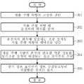
도 2 는 본 발명에 따른 자율 주행 차량의 운전모드 전환 방법에 대한 일실시예 흐름도,
도 3 은 본 발명에 따른 정보 표시부가 표시하는 정보의 일예시도이다.1 is a block diagram of an apparatus for changing an operation mode of an autonomous vehicle according to an embodiment of the present invention.
FIG. 2 is a flowchart illustrating an operation mode switching method for an autonomous vehicle according to an embodiment of the present invention.
3 is an example of information displayed by the information display unit according to the present invention.
상술한 목적, 특징 및 장점은 첨부된 도면을 참조하여 상세하게 후술되어 있는 상세한 설명을 통하여 보다 명확해 질 것이며, 그에 따라 본 발명이 속하는 기술분야에서 통상의 지식을 가진 자가 본 발명의 기술적 사상을 용이하게 실시할 수 있을 것이다. 또한, 본 발명을 설명함에 있어서 본 발명과 관련된 공지 기술에 대한 구체적인 설명이 본 발명의 요지를 불필요하게 흐릴 수 있다고 판단되는 경우에 그 상세한 설명을 생략하기로 한다. 이하, 첨부된 도면을 참조하여 본 발명에 따른 바람직한 실시예를 상세히 설명하기로 한다.BRIEF DESCRIPTION OF THE DRAWINGS The above and other objects, features and advantages of the present invention will become more apparent from the following detailed description of the present invention when taken in conjunction with the accompanying drawings, It can be easily carried out. In the following description, well-known functions or constructions are not described in detail since they would obscure the invention in unnecessary detail. Hereinafter, preferred embodiments of the present invention will be described in detail with reference to the accompanying drawings.
도 1 은 본 발명에 따른 자율 주행 차량의 운전모드 전환 장치에 대한 일실시예 구성도이다.1 is a block diagram of an apparatus for changing an operation mode of an autonomous vehicle according to an embodiment of the present invention.
도 1에 도시된 바와 같이, 본 발명에 따른 자율 주행 차량의 운전모드 전환 장치는, 고장 진단부(10), 운전자 감지부(20), 제어부(30), 정보 수집부(40), 및 정보 표시부(50)를 포함한다.1, an apparatus for switching an operation mode of an autonomous vehicle according to the present invention includes a
상기 각 구성요소의 설명에 앞서, 본 발명에 따른 자율 주행 차량은 운전석에는 물론 뒷좌석에도 조종 장치는 물론 차량을 조종하는데 필요한 각종 정보를 표시하는 정보 표시부(50)가 구비되어 있다.Prior to the description of each of the above components, the autonomous vehicle according to the present invention is provided with an
따라서, 운전자는 뒷좌석에 위치하고 있어도 정상적으로 제어권을 넘겨받아 수동으로 자율 주행 차량을 조종할 수 있다. 이때, 조종 장치는 터치 패드 형태로 구현될 수도 있고, 조이스틱 형태로 구현될 수 있으며, 이러한 조종 장치는 차량의 가/감속 제어가 가능하며, 비상정지 버튼을 구비하고 있어 운전자가 언제든 차량을 정지시킬 수 있도록 한다.Therefore, even if the driver is located in the back seat, he can control the autonomous driving vehicle manually by taking over the control right normally. At this time, the steering device may be implemented as a touch pad or a joystick type. Such a steering device may be capable of controlling acceleration / deceleration of the vehicle and includes an emergency stop button so that the driver can stop the vehicle at any time .
최근, 미국의 네바다 및 플로리다 주에서 무인 자율주행차량에 대한 법안이 통과되면서 일반 도로에서도 자율 주행 차량과 일반차량이 함께 주행할 수 있게 되었다. 하지만, 안전을 이유로 자율 주행 차량에는 반드시 운전자(수동 운전모드가 아닌 이상 차량을 운전하지 않는다)가 탑승하도록 되어 있다.Recently, the legislation passed on unmanned autonomous vehicles in Nevada and Florida in the United States, allowing autonomous vehicles and ordinary vehicles to run on public roads. However, for safety reasons, the autonomous vehicle must be equipped with a driver (not driving the vehicle unless it is in the manual operation mode).
따라서, 자율 주행 차량의 고장 진단시 수동 운전모드로 전환하는 동시에 제어권을 운전자에게 넘겨 운전자로 하여금 주변 차량에 피해가 없도록 고장난 자율 주행 차량을 조종하도록 하고 있다.Therefore, when diagnosing the failure of the autonomous vehicle, the control mode is switched to the manual operation mode and the control right is handed over to the driver so that the driver can control the failed autonomous vehicle so as not to damage the surrounding vehicle.
먼저, 고장 진단부(10)는 차량의 고장을 진단한다. 즉, 고장 진단부(10)는 자율 주행 차량 내 각종 기기가 정상 상태일 때 출력하는 값을 저장하고 있고, 어느 하나의 기기라도 비정상적인 값을 출력하는 경우, 특히 자율 주행 차량의 정상 주행에 직접적인 영향을 미치는 기기가 비정상인 경우, 자율 주행 차량에 고장이 발생한 것으로 진단한다. 이때, 자율 주행 차량은 자체 치유가 불가하므로 반드시 수동 조종에 의해 안전 지역으로 이동해야 한다.First, the
운전자 감지부(20)는 자율 주행 차량 내 운전자의 위치를 감지한다. 본 발명이 적용되는 자율 주행 차량은 뒷좌석에도 조종 장치 및 정보 표시부(50)가 구비되어 있어, 자율 주행 차량의 고장 진단시 제어권을 넘겨주기 전에 반드시 운전자의 위치를 감지해야 한다.The
이러한 운전자 감지부(20)는 차량 내 카메라를 통해 획득한 영상을 기반으로 운전자의 위치를 감지할 수도 있고, 적외선 센서를 통해 운전자의 위치를 감지할 수도 있으며, 안전벨트의 착용 여부를 통해 운전자의 위치를 감지할 수도 있다.The
제어부(30)는 운전자 감지부(20)가 감지한 운전자의 위치에 상응하는 조종 장치로 자율 주행 차량의 제어권을 넘기고, 아울러 상기 조종 장치의 위치에 상응하는 정보 표시부(50)로 운전에 필요한 정보를 전달하도록 정보 수집부(40)를 제어한다.The
즉, 제어부(30)는 운전자 감지부(20)가 운전자의 위치를 감지함에 따라 해당 위치에 존재하는 조종 장치를 활성화시켜 운전자에 의한 수동 조종이 가능하도록 한다.That is, as the
또한, 제어부(30)는 정보 수집부(40)가 수집한 각종 정보, 즉 차량의 근접 주변 영상(Near Around View), 차량의 원거리 주변 영상(Far Around View), 주변 차량과의 근접도(위험도) 정보(Critical Level), 클러스터 내 계기 정보(Vehicle Info) 등을 운전자의 위치에 상응하는 정보 표시부(50)로 전달하도록 정보 수집부(40)를 제어한다.In addition, the
정보 수집부(40)는 뒷좌석에 있는 운전자가 자율 주행 차량을 조종할 수 있도록 차량의 근접 주변 영상, 차량의 원거리 주변 영상, 주변 차량과의 근접도(위험도) 정보, 클러스터 내 계기 정보(조향 정보 포함) 등을 수집한다.The
이러한 정보 수집부(40)는 차량 네트워크를 통해 차량 내 각종 시스템으로부터 정보를 수집한다.The
정보 표시부(50)는 차량의 뒷좌석 등에 위치하여 뒷좌석에 앉아 있는 운전자가 자율 주행 차량을 조종할 수 있도록 정보 수집부(40)가 수집한 각종 정보를 표시한다.The
이러한 정보 표시부(50)가 표시하는 정보는 일예로 도 3에 도시된 바와 같다. 여기서, 주변 차량과의 근접도(위험도) 정보(Critical Level)는 위험도에 따라 서로 다른 색으로 표시할 수 있다.The information displayed by the
도 2 는 본 발명에 따른 자율 주행 차량의 운전모드 전환 방법에 대한 일실시예 흐름도이다.2 is a flowchart illustrating an operation mode switching method for an autonomous vehicle according to an embodiment of the present invention.
먼저, 고장 진단부(10)가 자율 주행 차량의 고장을 진단한다(201).First, the failure diagnosis unit 10 diagnoses the failure of the autonomous vehicle (201).
이후, 운전자 감지부(20)가 상기 자율 주행 차량 내 운전자의 위치를 감지한다(202).Thereafter, the
이후, 제어부(30)가 상기 감지된 운전자의 위치에 상응하는 조종 장치로 상기 자율 주행 차량의 제어권을 넘긴다(203).Thereafter, the
이후, 제어부(30)의 제어하에 정보 수집부(40)가 수집한 상기 자율 주행 차량의 운전에 필요한 각종 정보를 상기 조종 장치에 매칭되는 정보 표시부(50)로 전달한다(204).Thereafter, various information necessary for the operation of the autonomous vehicle collected by the
이후, 상기 정보 표시부(50)가 정보 수집부(40)로부터 전달받은 정보를 표시한다(205).Then, the
이러한 과정을 통해, 자율 주행 차량의 고장 진단시 운전자가 자율 주행 차량 내 어디에 있더라도 제어권을 넘겨줄 수 있다.Through this process, the driver can pass the control right anywhere in the autonomous vehicle when diagnosing the failure of the autonomous vehicle.
한편, 전술한 바와 같은 본 발명의 방법은 컴퓨터 프로그램으로 작성이 가능하다. 그리고 상기 프로그램을 구성하는 코드 및 코드 세그먼트는 당해 분야의 컴퓨터 프로그래머에 의하여 용이하게 추론될 수 있다. 또한, 상기 작성된 프로그램은 컴퓨터가 읽을 수 있는 기록매체(정보저장매체)에 저장되고, 컴퓨터에 의하여 판독되고 실행됨으로써 본 발명의 방법을 구현한다. 그리고 상기 기록매체는 컴퓨터가 판독할 수 있는 모든 형태의 기록매체를 포함한다.Meanwhile, the method of the present invention as described above can be written in a computer program. And the code and code segments constituting the program can be easily deduced by a computer programmer in the field. In addition, the created program is stored in a computer-readable recording medium (information storage medium), and is read and executed by a computer to implement the method of the present invention. And the recording medium includes all types of recording media readable by a computer.
이상에서 설명한 본 발명은, 본 발명이 속하는 기술 분야에서 통상의 지식을 가진 자에게 있어 본 발명의 기술적 사상을 벗어나지 않는 범위 내에서 여러 가지 치환, 변형 및 변경이 가능하므로 전술한 실시예 및 첨부된 도면에 의해 한정되는 것이 아니다.It will be apparent to those skilled in the art that various modifications and variations can be made in the present invention without departing from the spirit or scope of the invention. The present invention is not limited to the drawings.
10 : 고장 진단부20 : 운전자 감지부
30 : 제어부40 : 정보 수집부
50 : 정보 표시부10: Failure diagnosis part 20: Driver detection part
30: control unit 40: information collecting unit
50: information display section
Claims (7)
Translated fromKorean상기 자율 주행 차량 내 운전자의 위치를 감지하는 운전자 감지부;
상기 운전자 감지부가 감지한 운전자의 위치에 상응하는 조종 장치로 상기 자율 주행 차량의 제어권을 넘기고, 상기 조종 장치의 위치에 상응하는 정보 표시부로 운전에 필요한 각종 정보를 전달하도록 정보 수집부를 제어하는 제어부;
상기 자율 주행 차량의 운전에 필요한 각종 정보를 수집하는 정보 수집부; 및
상기 정보 수집부가 수집한 각종 정보를 표시하는 적어도 하나 이상의 정보 표시부를 포함하되,
상기 조종 장치는,
상기 자율 주행 차량의 뒷좌석에 위치하는 것을 특징으로 하는 자율 주행 차량의 운전모드 전환 장치.A fault diagnosis unit for diagnosing a fault of the autonomous vehicle;
A driver sensing unit for sensing a position of a driver in the autonomous vehicle;
A control unit for passing the control right of the autonomous vehicle to the control unit corresponding to the position of the driver sensed by the driver sensing unit and controlling the information collecting unit to transmit various information necessary for the operation to the information display unit corresponding to the position of the control unit;
An information collecting unit for collecting various kinds of information necessary for the operation of the autonomous vehicle; And
And at least one information display unit for displaying various information collected by the information collecting unit,
The steering apparatus includes:
Wherein the operating mode switching means is located in the rear seat of the autonomous traveling vehicle.
상기 조종 장치는,
터치 패드 형태의 조종 장치인 것을 특징으로 하는 자율 주행 차량의 운전모드 전환 장치.3. The method of claim 2,
The steering apparatus includes:
Wherein the control device is a touchpad type steering device.
상기 조종 장치는,
조이스틱 형태의 조종 장치인 것을 특징으로 하는 자율 주행 차량의 운전모드 전환 장치.3. The method of claim 2,
The steering apparatus includes:
Wherein the control unit is a joystick type control unit.
상기 정보 수집부는,
상기 자율 주행 차량의 근접 주변 영상, 상기 자율 주행 차량의 원거리 주변 영상, 주변 차량과의 근접도(위험도) 정보, 클러스터 내 계기 정보 중 적어도 하나 이상을 수집하는 것을 특징으로 하는 자율 주행 차량의 운전모드 전환 장치.3. The method of claim 2,
The information collecting unit,
Wherein at least one of the proximity peripheral image of the autonomous driving vehicle, the remote peripheral image of the autonomous driving vehicle, the proximity (risk) information of the autonomous traveling vehicle, and the in-cluster instrument information is collected Switching device.
운전자 감지부가 상기 자율 주행 차량 내 운전자의 위치를 감지하는 단계;
제어부가 상기 감지된 운전자의 위치에 상응하는 조종 장치로 상기 자율 주행 차량의 제어권을 넘겨주는 단계;
상기 제어부의 제어하에 정보 수집부가 수집한 상기 자율 주행 차량의 운전에 필요한 각종 정보를 상기 조종 장치에 매칭되는 정보 표시부로 전달하는 단계; 및
상기 정보 표시부가 상기 전달받은 정보를 표시하는 단계를 포함하되,
상기 조종 장치는,
상기 자율 주행 차량의 뒷좌석에 위치하는 것을 특징으로 하는 자율 주행 차량의 운전모드 전환 방법.Diagnosing a failure diagnosis unit of the autonomous vehicle;
The driver sensing unit sensing a position of the driver in the autonomous vehicle;
The control unit forwards the control right of the autonomous vehicle to the control unit corresponding to the sensed driver's position;
Transferring various information necessary for operation of the autonomous vehicle collected by the information collecting unit under the control of the control unit to an information display unit matched with the steering apparatus; And
And the information display unit displays the received information,
The steering apparatus includes:
Wherein the control unit is located in the rear seat of the autonomous vehicle.
상기 정보 표시부가 표시하는 정보는,
상기 자율 주행 차량의 근접 주변 영상, 상기 자율 주행 차량의 원거리 주변 영상, 주변 차량과의 근접도(위험도) 정보, 클러스터 내 계기 정보 중 적어도 하나 이상을 포함하는 것을 특징으로 하는 자율 주행 차량의 운전모드 전환 방법.The method according to claim 6,
Wherein the information displayed by the information display unit includes:
Wherein the autonomous vehicle includes at least one of a proximity peripheral image of the autonomous driving vehicle, a remote peripheral image of the autonomous driving vehicle, proximity (risk) information of the autonomous traveling vehicle, Conversion method.
Priority Applications (2)
| Application Number | Priority Date | Filing Date | Title |
|---|---|---|---|
| KR1020120155001AKR101449210B1 (en) | 2012-12-27 | 2012-12-27 | Apparatus for converting driving mode of autonomous vehicle and method thereof |
| US13/902,024US8812186B2 (en) | 2012-12-27 | 2013-05-24 | Driving mode changing method and apparatus of autonomous navigation vehicle |
Applications Claiming Priority (1)
| Application Number | Priority Date | Filing Date | Title |
|---|---|---|---|
| KR1020120155001AKR101449210B1 (en) | 2012-12-27 | 2012-12-27 | Apparatus for converting driving mode of autonomous vehicle and method thereof |
Publications (2)
| Publication Number | Publication Date |
|---|---|
| KR20140084959A KR20140084959A (en) | 2014-07-07 |
| KR101449210B1true KR101449210B1 (en) | 2014-10-08 |
Family
ID=51018119
Family Applications (1)
| Application Number | Title | Priority Date | Filing Date |
|---|---|---|---|
| KR1020120155001AActiveKR101449210B1 (en) | 2012-12-27 | 2012-12-27 | Apparatus for converting driving mode of autonomous vehicle and method thereof |
Country Status (2)
| Country | Link |
|---|---|
| US (1) | US8812186B2 (en) |
| KR (1) | KR101449210B1 (en) |
Cited By (1)
| Publication number | Priority date | Publication date | Assignee | Title |
|---|---|---|---|---|
| KR101646134B1 (en) | 2015-05-06 | 2016-08-05 | 현대자동차 주식회사 | Autonomous vehicle and a control method |
Families Citing this family (41)
| Publication number | Priority date | Publication date | Assignee | Title |
|---|---|---|---|---|
| DE102013013539A1 (en)* | 2013-08-14 | 2015-02-19 | GM Global Technology Operations, LLC (n.d. Ges. d. Staates Delaware) | Driver assistance system and method for operating a driver assistance system |
| US9365213B2 (en)* | 2014-04-30 | 2016-06-14 | Here Global B.V. | Mode transition for an autonomous vehicle |
| US10373259B1 (en) | 2014-05-20 | 2019-08-06 | State Farm Mutual Automobile Insurance Company | Fully autonomous vehicle insurance pricing |
| US9972054B1 (en) | 2014-05-20 | 2018-05-15 | State Farm Mutual Automobile Insurance Company | Accident fault determination for autonomous vehicles |
| US10599155B1 (en) | 2014-05-20 | 2020-03-24 | State Farm Mutual Automobile Insurance Company | Autonomous vehicle operation feature monitoring and evaluation of effectiveness |
| US11669090B2 (en) | 2014-05-20 | 2023-06-06 | State Farm Mutual Automobile Insurance Company | Autonomous vehicle operation feature monitoring and evaluation of effectiveness |
| US20210133871A1 (en) | 2014-05-20 | 2021-05-06 | State Farm Mutual Automobile Insurance Company | Autonomous vehicle operation feature usage recommendations |
| US9631933B1 (en) | 2014-05-23 | 2017-04-25 | Google Inc. | Specifying unavailable locations for autonomous vehicles |
| US9436182B2 (en) | 2014-05-23 | 2016-09-06 | Google Inc. | Autonomous vehicles |
| US10387962B1 (en) | 2014-07-21 | 2019-08-20 | State Farm Mutual Automobile Insurance Company | Methods of reconstructing an accident scene using telematics data |
| US10157423B1 (en) | 2014-11-13 | 2018-12-18 | State Farm Mutual Automobile Insurance Company | Autonomous vehicle operating style and mode monitoring |
| KR101650791B1 (en)* | 2015-03-19 | 2016-08-25 | 현대자동차주식회사 | Vehicle, and method for controlling thereof |
| KR102043060B1 (en)* | 2015-05-08 | 2019-11-11 | 엘지전자 주식회사 | Autonomous drive apparatus and vehicle including the same |
| US9802638B1 (en) | 2015-06-19 | 2017-10-31 | Waymo Llc | Removable manual controls for an autonomous vehicle |
| US9805601B1 (en) | 2015-08-28 | 2017-10-31 | State Farm Mutual Automobile Insurance Company | Vehicular traffic alerts for avoidance of abnormal traffic conditions |
| US9587952B1 (en) | 2015-09-09 | 2017-03-07 | Allstate Insurance Company | Altering autonomous or semi-autonomous vehicle operation based on route traversal values |
| US11719545B2 (en) | 2016-01-22 | 2023-08-08 | Hyundai Motor Company | Autonomous vehicle component damage and salvage assessment |
| US10324463B1 (en) | 2016-01-22 | 2019-06-18 | State Farm Mutual Automobile Insurance Company | Autonomous vehicle operation adjustment based upon route |
| US10493936B1 (en) | 2016-01-22 | 2019-12-03 | State Farm Mutual Automobile Insurance Company | Detecting and responding to autonomous vehicle collisions |
| US10395332B1 (en) | 2016-01-22 | 2019-08-27 | State Farm Mutual Automobile Insurance Company | Coordinated autonomous vehicle automatic area scanning |
| US11441916B1 (en) | 2016-01-22 | 2022-09-13 | State Farm Mutual Automobile Insurance Company | Autonomous vehicle trip routing |
| US10134278B1 (en) | 2016-01-22 | 2018-11-20 | State Farm Mutual Automobile Insurance Company | Autonomous vehicle application |
| US11242051B1 (en) | 2016-01-22 | 2022-02-08 | State Farm Mutual Automobile Insurance Company | Autonomous vehicle action communications |
| US9989963B2 (en) | 2016-02-25 | 2018-06-05 | Ford Global Technologies, Llc | Autonomous confidence control |
| US10026317B2 (en) | 2016-02-25 | 2018-07-17 | Ford Global Technologies, Llc | Autonomous probability control |
| US10289113B2 (en) | 2016-02-25 | 2019-05-14 | Ford Global Technologies, Llc | Autonomous occupant attention-based control |
| US20170359519A1 (en)* | 2016-06-08 | 2017-12-14 | General Motors Llc | Vehicle information system and method |
| KR102565928B1 (en)* | 2016-07-21 | 2023-08-11 | 현대자동차주식회사 | Automatic Driving control apparatus, vehicle having the same and method for controlling the same |
| JP6675487B2 (en)* | 2016-08-10 | 2020-04-01 | 日立オートモティブシステムズ株式会社 | Vehicle control device |
| KR101951424B1 (en)* | 2016-10-27 | 2019-02-22 | 엘지전자 주식회사 | Vehicle control device mounted at vehicle and method for controlling the vehicle |
| JP6686869B2 (en)* | 2016-12-22 | 2020-04-22 | 株式会社デンソー | Driving change control device and driving change control method |
| WO2018154995A1 (en)* | 2017-02-22 | 2018-08-30 | ジヤトコ株式会社 | Vehicle control device and vehicle control method |
| KR102396993B1 (en)* | 2017-10-12 | 2022-05-16 | 르노코리아자동차 주식회사 | Conditions for switching to manual mode in autonomous vehicles |
| KR101943422B1 (en)* | 2018-05-11 | 2019-01-29 | 윤여표 | A system and a method of safety inspection for an autonomous vehicle |
| CN109710104A (en)* | 2018-11-05 | 2019-05-03 | 广州小鹏汽车科技有限公司 | A kind of method of toch control and system of vehicle-mounted middle control large-size screen monitors |
| KR102122886B1 (en)* | 2018-11-23 | 2020-06-15 | 재단법인대구경북과학기술원 | System for assessing the safety of control transition between an autonomous car and a driver using driving simulator |
| KR102169991B1 (en)* | 2018-12-27 | 2020-10-26 | 주식회사 현대케피코 | Method and System for Testing an Automatic Running Mode of a Vehicle Performed by an In-vehicle Control Device |
| WO2020204225A1 (en)* | 2019-04-02 | 2020-10-08 | 엘지전자 주식회사 | Vehicle control method |
| JP7381230B2 (en)* | 2019-06-28 | 2023-11-15 | トヨタ自動車株式会社 | Autonomous vehicle operating device |
| KR102829532B1 (en)* | 2019-08-07 | 2025-07-07 | 현대자동차주식회사 | Apparatus for controlling behavior of autonomous vehicle and method thereof |
| KR20240062628A (en)* | 2022-11-02 | 2024-05-09 | 현대자동차주식회사 | Vehicle for performing minimal risk maneuver and method of operating the vehicle |
Citations (3)
| Publication number | Priority date | Publication date | Assignee | Title |
|---|---|---|---|---|
| JPH09160643A (en)* | 1995-12-11 | 1997-06-20 | Toyota Motor Corp | Vehicle diagnostic system |
| US20060089766A1 (en) | 2004-10-22 | 2006-04-27 | James Allard | Systems and methods for control of an unmanned ground vehicle |
| KR101289668B1 (en) | 2012-05-23 | 2013-07-26 | 한국과학기술원 | Moving instrument driving system of change of driver's location |
Family Cites Families (16)
| Publication number | Priority date | Publication date | Assignee | Title |
|---|---|---|---|---|
| JP3239727B2 (en)* | 1995-12-05 | 2001-12-17 | トヨタ自動車株式会社 | Automatic driving control device for vehicles |
| US6181996B1 (en)* | 1999-11-18 | 2001-01-30 | International Business Machines Corporation | System for controlling vehicle information user interfaces |
| JP2003154900A (en)* | 2001-11-22 | 2003-05-27 | Pioneer Electronic Corp | Rear entertainment system and method of controlling the same |
| AU2006306522B9 (en)* | 2005-10-21 | 2011-12-08 | Deere & Company | Networked multi-role robotic vehicle |
| JP2007249364A (en)* | 2006-03-14 | 2007-09-27 | Denso Corp | Safe driving support system and device |
| US20070293989A1 (en)* | 2006-06-14 | 2007-12-20 | Deere & Company, A Delaware Corporation | Multiple mode system with multiple controllers |
| US8139109B2 (en)* | 2006-06-19 | 2012-03-20 | Oshkosh Corporation | Vision system for an autonomous vehicle |
| US8374743B2 (en) | 2008-05-16 | 2013-02-12 | GM Global Technology Operations LLC | Method and apparatus for driver control of a limited-ability autonomous vehicle |
| DE102008024929A1 (en)* | 2008-05-23 | 2009-11-26 | Wabco Gmbh | Driver assistance system |
| DE102009037680A1 (en)* | 2009-08-14 | 2011-02-17 | Volkswagen Ag | Motor vehicle cockpit unit, for at least two seats side-by-side, has a steering unit sliding on the instrument panel for driving from a selected front seat |
| KR101291067B1 (en) | 2009-11-26 | 2013-08-07 | 한국전자통신연구원 | Car control apparatus and its autonomous driving method, local sever apparatus and its autonomous driving service method, whole region sever apparatus and its autonomous driving service method |
| US8509982B2 (en)* | 2010-10-05 | 2013-08-13 | Google Inc. | Zone driving |
| KR101063302B1 (en) | 2010-10-05 | 2011-09-07 | 국방과학연구소 | Autonomous driving control device and method of unmanned vehicle |
| US20120271500A1 (en)* | 2011-04-20 | 2012-10-25 | GM Global Technology Operations LLC | System and method for enabling a driver to input a vehicle control instruction into an autonomous vehicle controller |
| US9464410B2 (en)* | 2011-05-19 | 2016-10-11 | Deere & Company | Collaborative vehicle control using both human operator and automated controller input |
| US8751105B2 (en)* | 2012-01-05 | 2014-06-10 | Ford Global Technologies, Llc | Restricted operation of vehicle driven by secondary driver with rear passengers |
- 2012
- 2012-12-27KRKR1020120155001Apatent/KR101449210B1/enactiveActive
- 2013
- 2013-05-24USUS13/902,024patent/US8812186B2/enactiveActive
Patent Citations (3)
| Publication number | Priority date | Publication date | Assignee | Title |
|---|---|---|---|---|
| JPH09160643A (en)* | 1995-12-11 | 1997-06-20 | Toyota Motor Corp | Vehicle diagnostic system |
| US20060089766A1 (en) | 2004-10-22 | 2006-04-27 | James Allard | Systems and methods for control of an unmanned ground vehicle |
| KR101289668B1 (en) | 2012-05-23 | 2013-07-26 | 한국과학기술원 | Moving instrument driving system of change of driver's location |
Cited By (2)
| Publication number | Priority date | Publication date | Assignee | Title |
|---|---|---|---|---|
| KR101646134B1 (en) | 2015-05-06 | 2016-08-05 | 현대자동차 주식회사 | Autonomous vehicle and a control method |
| US9786181B2 (en) | 2015-05-06 | 2017-10-10 | Hyundai Motor Company | Autonomous vehicle and control method thereof |
Also Published As
| Publication number | Publication date |
|---|---|
| US8812186B2 (en) | 2014-08-19 |
| US20140188322A1 (en) | 2014-07-03 |
| KR20140084959A (en) | 2014-07-07 |
Similar Documents
| Publication | Publication Date | Title |
|---|---|---|
| KR101449210B1 (en) | Apparatus for converting driving mode of autonomous vehicle and method thereof | |
| US12198552B1 (en) | Occupant facing vehicle display | |
| AU2021202720B2 (en) | Detecting and responding to propulsion and steering system errors for autonomous vehicles | |
| KR102276096B1 (en) | Method for calculating insertion of additional information for displaying on a display unit, apparatus for performing the method and motor vehicle and computer program | |
| US11220288B2 (en) | Method and device for the control of a safety-relevant process and transportation vehicle | |
| US10248116B2 (en) | Remote operation of autonomous vehicle in unexpected environment | |
| CA3010882C (en) | Fall back trajectory systems for autonomous vehicles | |
| US9551992B1 (en) | Fall back trajectory systems for autonomous vehicles | |
| KR101470190B1 (en) | Apparatus for processing trouble of autonomous driving system and method thereof | |
| US20190179305A1 (en) | Safety of autonomous vehicles using a virtual augmented support environment | |
| US20180086336A1 (en) | Autonomous vehicle: modular architecture | |
| CN107249953A (en) | Autonomous manipulative for autonomous vehicle is notified | |
| KR101869340B1 (en) | Remote controll device and remote controll method for controlling autonomous vehicle | |
| EP3515780A1 (en) | Autonomous vehicle with modular architecture | |
| JP7609092B2 (en) | Computers, vehicles, servers, and mobile devices | |
| CN115963818A (en) | Method for controlling an automated vehicle, control device and storage device | |
| Zhong et al. | Autonomous shuttle operation for vulnerable populations: Lessons and experiences | |
| JP2024102514A (en) | Vehicle driving control system, vehicle driving control device, vehicle driving control method, and program | |
| Avery et al. | Autonomous People Mover | |
| KR20210062145A (en) | Integration module for advanced driver assistance system |
Legal Events
| Date | Code | Title | Description |
|---|---|---|---|
| A201 | Request for examination | ||
| PA0109 | Patent application | Patent event code:PA01091R01D Comment text:Patent Application Patent event date:20121227 | |
| PA0201 | Request for examination | ||
| E902 | Notification of reason for refusal | ||
| PE0902 | Notice of grounds for rejection | Comment text:Notification of reason for refusal Patent event date:20140312 Patent event code:PE09021S01D | |
| PG1501 | Laying open of application | ||
| E701 | Decision to grant or registration of patent right | ||
| PE0701 | Decision of registration | Patent event code:PE07011S01D Comment text:Decision to Grant Registration Patent event date:20140820 | |
| GRNT | Written decision to grant | ||
| PR0701 | Registration of establishment | Comment text:Registration of Establishment Patent event date:20141001 Patent event code:PR07011E01D | |
| PR1002 | Payment of registration fee | Payment date:20141001 End annual number:3 Start annual number:1 | |
| PG1601 | Publication of registration | ||
| FPAY | Annual fee payment | Payment date:20180928 Year of fee payment:5 | |
| PR1001 | Payment of annual fee | Payment date:20180928 Start annual number:5 End annual number:5 | |
| FPAY | Annual fee payment | Payment date:20190926 Year of fee payment:6 | |
| PR1001 | Payment of annual fee | Payment date:20190926 Start annual number:6 End annual number:6 | |
| PR1001 | Payment of annual fee | Payment date:20200928 Start annual number:7 End annual number:7 | |
| PR1001 | Payment of annual fee | Payment date:20210928 Start annual number:8 End annual number:8 | |
| PR1001 | Payment of annual fee | Payment date:20220927 Start annual number:9 End annual number:9 | |
| PR1001 | Payment of annual fee | Payment date:20230925 Start annual number:10 End annual number:12 |