KR101449160B1 - Apparatus and method for providing information of blind spot - Google Patents
Apparatus and method for providing information of blind spotDownload PDFInfo
- Publication number
- KR101449160B1 KR101449160B1KR1020120144896AKR20120144896AKR101449160B1KR 101449160 B1KR101449160 B1KR 101449160B1KR 1020120144896 AKR1020120144896 AKR 1020120144896AKR 20120144896 AKR20120144896 AKR 20120144896AKR 101449160 B1KR101449160 B1KR 101449160B1
- Authority
- KR
- South Korea
- Prior art keywords
- image
- view
- vehicle
- side area
- camera
- Prior art date
- Legal status (The legal status is an assumption and is not a legal conclusion. Google has not performed a legal analysis and makes no representation as to the accuracy of the status listed.)
- Expired - Fee Related
Links
Images


Classifications
- B—PERFORMING OPERATIONS; TRANSPORTING
- B60—VEHICLES IN GENERAL
- B60R—VEHICLES, VEHICLE FITTINGS, OR VEHICLE PARTS, NOT OTHERWISE PROVIDED FOR
- B60R1/00—Optical viewing arrangements; Real-time viewing arrangements for drivers or passengers using optical image capturing systems, e.g. cameras or video systems specially adapted for use in or on vehicles
- B60R1/02—Rear-view mirror arrangements
- B60R1/08—Rear-view mirror arrangements involving special optical features, e.g. avoiding blind spots, e.g. convex mirrors; Side-by-side associations of rear-view and other mirrors
- G—PHYSICS
- G06—COMPUTING OR CALCULATING; COUNTING
- G06V—IMAGE OR VIDEO RECOGNITION OR UNDERSTANDING
- G06V20/00—Scenes; Scene-specific elements
- G06V20/50—Context or environment of the image
- G06V20/56—Context or environment of the image exterior to a vehicle by using sensors mounted on the vehicle
- B—PERFORMING OPERATIONS; TRANSPORTING
- B60—VEHICLES IN GENERAL
- B60R—VEHICLES, VEHICLE FITTINGS, OR VEHICLE PARTS, NOT OTHERWISE PROVIDED FOR
- B60R21/00—Arrangements or fittings on vehicles for protecting or preventing injuries to occupants or pedestrians in case of accidents or other traffic risks
- B—PERFORMING OPERATIONS; TRANSPORTING
- B60—VEHICLES IN GENERAL
- B60W—CONJOINT CONTROL OF VEHICLE SUB-UNITS OF DIFFERENT TYPE OR DIFFERENT FUNCTION; CONTROL SYSTEMS SPECIALLY ADAPTED FOR HYBRID VEHICLES; ROAD VEHICLE DRIVE CONTROL SYSTEMS FOR PURPOSES NOT RELATED TO THE CONTROL OF A PARTICULAR SUB-UNIT
- B60W40/00—Estimation or calculation of non-directly measurable driving parameters for road vehicle drive control systems not related to the control of a particular sub unit, e.g. by using mathematical models
- B60W40/02—Estimation or calculation of non-directly measurable driving parameters for road vehicle drive control systems not related to the control of a particular sub unit, e.g. by using mathematical models related to ambient conditions
- G—PHYSICS
- G06—COMPUTING OR CALCULATING; COUNTING
- G06V—IMAGE OR VIDEO RECOGNITION OR UNDERSTANDING
- G06V10/00—Arrangements for image or video recognition or understanding
- G06V10/10—Image acquisition
- G06V10/12—Details of acquisition arrangements; Constructional details thereof
- G06V10/14—Optical characteristics of the device performing the acquisition or on the illumination arrangements
- G06V10/147—Details of sensors, e.g. sensor lenses
- G—PHYSICS
- G06—COMPUTING OR CALCULATING; COUNTING
- G06V—IMAGE OR VIDEO RECOGNITION OR UNDERSTANDING
- G06V20/00—Scenes; Scene-specific elements
- G06V20/50—Context or environment of the image
- G06V20/56—Context or environment of the image exterior to a vehicle by using sensors mounted on the vehicle
- G06V20/58—Recognition of moving objects or obstacles, e.g. vehicles or pedestrians; Recognition of traffic objects, e.g. traffic signs, traffic lights or roads
Landscapes
- Engineering & Computer Science (AREA)
- Physics & Mathematics (AREA)
- Multimedia (AREA)
- General Physics & Mathematics (AREA)
- Theoretical Computer Science (AREA)
- Mechanical Engineering (AREA)
- General Health & Medical Sciences (AREA)
- Vascular Medicine (AREA)
- Health & Medical Sciences (AREA)
- Automation & Control Theory (AREA)
- Mathematical Physics (AREA)
- Transportation (AREA)
- Closed-Circuit Television Systems (AREA)
- Image Analysis (AREA)
- Image Processing (AREA)
- Traffic Control Systems (AREA)
Abstract
Translated fromKoreanDescription
Translated fromKorean본 발명은 차량의 사각지대 정보 제공 장치 및 방법에 관한 것으로, 초광각 측면 영상으로부터 사각지대에 위치한 사이드 영역 및 후측방 영역의 물체를 검출하도록 하는 기술에 관한 것이다.The present invention relates to an apparatus and method for providing a dead zone information of a vehicle, and more particularly, to a technique for detecting an object in a side region and a rear side region located in a dead zone from an ultra-wide angle side image.
일반적으로, 차량에 탑승한 운전자는 사이드 미러를 통해 후측방의 상태를 확인하게 된다. 하지만, 사이드 미러가 수용할 수 있는 범위가 한정적이어서, 사이드 미러를 통해 감시할 수 없는 사각지대가 발생하게 된다. 따라서, 운전자는 사각지대의 상태를 확인할 수 없어 사고 발생이 증대되는 문제가 있다.Generally, a driver boarding a vehicle checks the state of the rear side through the side mirror. However, since the range that the side mirror can accommodate is limited, a dead zone that can not be monitored through the side mirror occurs. Therefore, the driver can not confirm the state of the blind spot, thereby causing an increase in the occurrence of an accident.
이를 위해, 차량에 센서를 배치하여, 센서를 통해 사각지대의 물체를 검출하고, 이로써 운전자는 사각지대의 상황을 사전에 인지할 수 있게 된다. 하지만, 별도의 센서를 차량에 부착해야할 뿐만 아니라, 기상악화 등의 외부환경에 의한 영향 및 센서 자체의 특성 상 센서값 측정에 오차가 발생할 수 있는 문제가 있다.For this purpose, a sensor is disposed in the vehicle, and an object in a dead zone is detected through the sensor, whereby the driver can recognize the situation of the dead zone in advance. However, there is a problem that not only a separate sensor must be attached to the vehicle but also an error may occur in the sensor value measurement due to the influence of external environment such as weather deterioration and the characteristics of the sensor itself.
[특허문헌] 국내등록특허 제10-0062301호.[Patent Literature] Domestic Registration No. 10-0062301.
본 발명의 목적은, 초광각의 사이드 카메라 영상으로부터 사각지대에 위치한 사이드 영역 및 후측방 영역의 물체를 검출하도록 하는 차량의 사각지대 정보 제공 장치 및 방법을 제공함에 있다.An object of the present invention is to provide an apparatus and method for providing a dead zone information of a vehicle which detects an object in a side region and a rear side region located in a dead zone from an ultra wide angle side camera image.
특히, 본 발명은, 하나의 사이드 카메라 영상 내에서 물체의 위치에 따른 형상의 변화가 최소화될 수 있는 사이드 영역 및 후측방 영역을 지정하고, 지정된 두 영역의 영상을 각각 뷰 변환함으로써, 물체 검출 정확도가 증대되도록 하는데 그 목적이 있다.Particularly, the present invention is characterized by specifying a side region and a rear side region in which a change in shape according to the position of an object can be minimized in one side camera image, And the like.
또한, 본 발명의 다른 목적은, 초광각의 사이드 카메라 영상으로부터 분할된 사이드 영역 및 후측방 영역의 영상을 뷰 변환한 영상들로부터 특징점을 추출하여 사각지대의 물체를 검출하여 물체의 위치 검출정확도가 향상되도록 하는 차량의 사각지대 정보 제공 장치 및 방법을 제공함에 있다.Another object of the present invention is to extract the feature point from the view-converted images of the side region and the back side region divided from the super-wide-angle side camera image to detect the object in the blind zone and improve the accuracy of detecting the position of the object And a method for providing a blind zone information of a vehicle.
상기의 목적을 달성하기 위한 본 발명에 따른 차량의 사각지대 정보 제공 장치는, 차량의 사각지대를 포함하는 영상을 촬영하는 사이드 카메라로부터 입력된 촬영 영상으로부터 기 정의된 사이드 영역 및 후측방 영역을 검출하는 뷰 변환 영역 검출부, 및 상기 사이드 영역 및 상기 후측방 영역의 영상을 기 설정된 뷰 변환 파라미터에 따라 뷰 변환하여 상기 사이드 영역 및 상기 후측방 영역의 영상에 대응하는 뷰 변환 영상을 생성하는 뷰 변환부를 포함하는 것을 특징으로 한다.According to an aspect of the present invention, there is provided an apparatus for providing a blind zone information of a vehicle, the blind zone information including at least one of a side region and a back side region defined from a photographed image input from a side camera And a view conversion unit for generating a view conversion image corresponding to an image of the side area and the back side area by performing a view conversion on the image of the side area and the back side area according to predetermined view conversion parameters, .
상기 뷰 변환부는, 상기 뷰 변환 파라미터의 값이 룩업 테이블(Look up table)에 정의되어, 상기 룩업 테이블에 정의된 상기 뷰 변환 파라미터의 값에 따라 상기 사이드 영역 및 상기 후측방 영역의 영상을 각각 뷰 변환하는 것을 특징으로 한다.Wherein the view conversion unit is configured such that the value of the view conversion parameter is defined in a lookup table and the image of the side area and the back side area is respectively viewed from the viewpoint table according to the value of the view conversion parameter defined in the look- And converts the data.
상기 사이드 카메라는 초광각 카메라이고, 상기 뷰 변환부는 초광각의 촬영 영상을 촬영각 보다 좁은 각의 영상으로 뷰 변환하는 것을 특징으로 한다.Wherein the side camera is an ultra-wide angle camera, and the view conversion unit converts the ultra-wide angle photographing image into an angle image narrower than the photographing angle.
상기 뷰 변환부는, 상기 사이드 영역의 영상을 제1 뷰 변환 파라미터로 뷰 변환하여 제1 뷰 변환영상을 생성하는 제1 뷰 변환부, 및 상기 후측방 영역의 영상을 제2 뷰 변환 파라미터로 뷰 변환하여 제2 뷰 변환영상을 생성하는 제2 뷰 변환부를 포함하는 것을 특징으로 한다.Wherein the view transformation unit includes a first view transformation unit for transforming an image of the side area into a first view transformation parameter to generate a first view transformation image, and a second view transformation unit for transforming the image of the rear side region into a view transformation And a second view transformation unit for generating a second view transformation image.
또한, 본 발명에 따른 장치는, 상기 뷰 변환 영상으로부터 특징점을 추출하는 특징점 추출부, 및 상기 뷰 변환 영상으로부터 추출된 특징점에 근거하여 상기 사각지대의 물체를 검출하는 검출부를 더 포함하는 것을 특징으로 한다.The apparatus according to the present invention further includes a feature point extracting unit that extracts feature points from the view transformation image and a detection unit that detects an object of the blind spot based on the feature points extracted from the view transformation image. do.
상기 검출부는, 상기 뷰 변환 영상으로부터 추출된 특징점과 기 저장된 차량의 특징점을 비교하여, 비교 결과에 따라 상기 사각지대에 위치한 차량을 검출하는 것을 특징으로 한다. 여기서, 상기 차량의 특징점은, 상기 차량의 전면, 측면, 하단 및 바퀴의 형상과 상기 차량의 모션 정보 중 적어도 하나를 포함하는 것을 특징으로 한다.The detecting unit compares the feature point extracted from the view-converted image with the feature point of the previously stored vehicle, and detects the vehicle located in the blind spot according to the comparison result. Here, the feature point of the vehicle includes at least one of a front surface, a side surface, a bottom surface of the vehicle, a shape of a wheel, and motion information of the vehicle.
한편, 상기의 목적을 달성하기 위한 본 발명에 따른 차량의 사각지대 정보 제공 방법은, 차량의 사각지대를 포함하는 영상을 촬영하는 사이드 카메라로부터 입력된 촬영 영상으로부터 기 정의된 사이드 영역 및 후측방 영역을 검출하는 단계, 및 상기 사이드 영역 및 상기 후측방 영역의 영상을 기 설정된 뷰 변환 파라미터에 따라 뷰 변환하여 상기 사이드 영역 및 상기 후측방 영역의 영상에 대응하는 뷰 변환 영상을 생성하는 단계를 포함하는 것을 특징으로 한다.According to another aspect of the present invention, there is provided a method of providing a blind zone information of a vehicle, the blind zone information including a side region defined in a captured image input from a side camera that captures an image including a blind spot of the vehicle, And generating a view transformation image corresponding to an image of the side region and the rear side region by performing a view transformation on the image of the side region and the rear side region according to a predetermined view transformation parameter .
상기 뷰 변환 영상을 생성하는 단계는, 상기 뷰 변환 파라미터의 값이 룩업 테이블(Look up table)에 정의되어, 상기 룩업 테이블에 정의된 상기 뷰 변환 파라미터의 값에 따라 상기 사이드 영역 및 상기 후측방 영역의 영상을 각각 뷰 변환하는 것을 특징으로 한다.Wherein the step of generating the view transformation image comprises the steps of: defining a value of the view transformation parameter in a lookup table, and determining a value of the view transformation parameter based on the value of the view transformation parameter defined in the lookup table; And the image of the image is converted into a view.
상기 뷰 변환 영상을 생성하는 단계는, 상기 사이드 영역의 영상을 제1 뷰 변환 파라미터로 뷰 변환하여 제1 뷰 변환영상을 생성하는 단계, 및 상기 후측방 영역의 영상을 제2 뷰 변환 파라미터로 뷰 변환하여 제2 뷰 변환영상을 생성하는 단계를 포함하는 것을 특징으로 한다.The generating of the view transformation image may include generating a first view transformation image by transforming the image of the side region into a first view transformation parameter, And generating a second view transformed image by transforming the second view transformed image.
또한, 본 발명에 따른 방법은, 상기 뷰 변환 영상으로부터 특징점을 추출하는 단계, 및 상기 뷰 변환 영상으로부터 추출된 특징점에 근거하여 상기 사각지대의 물체를 검출하는 단계를 포함하는 것을 특징으로 한다.The method may further include extracting a feature point from the view-transformed image, and detecting an object in the blind spot based on the feature point extracted from the view-transformed image.
상기 사각지대의 물체를 검출하는 단계는, 상기 뷰 변환 영상으로부터 추출된 특징점과 기 저장된 차량의 특징점을 비교하여, 비교 결과에 따라 상기 사각지대에 위치한 차량을 검출하는 것을 특징으로 한다. 여기서, 상기 차량의 특징점은, 상기 차량의 전면, 측면, 하단 및 바퀴의 형상과 상기 차량의 모션 정보 중 적어도 하나를 포함하는 것을 특징으로 한다.The detecting of the object in the dead zone may include comparing the feature point extracted from the view-converted image with the feature point of the stored vehicle, and detecting the vehicle located in the blind spot according to the comparison result. Here, the feature point of the vehicle includes at least one of a front surface, a side surface, a bottom surface of the vehicle, a shape of a wheel, and motion information of the vehicle.
본 발명에 따르면, 초광각의 사이드 카메라 영상으로부터 사각지대에 위치한 사이드 영역 및 후측방 영역의 물체를 검출함으로써 사각지대의 물체를 용이하게 검출할 수 있는 이점이 있다.According to the present invention, an object in a dead zone can be easily detected by detecting an object in a side region and a rear side region located in a dead zone from an ultra-wide-angle side camera image.
특히, 본 발명은, 하나의 사이드 카메라 영상 내에서 물체의 위치에 따른 형상의 변화가 최소화될 수 있는 사이드 영역 및 후측방 영역을 지정하고, 지정된 두 영역의 영상을 각각 뷰 변환함으로써, 물체 검출 정확도를 향상시키는 효과가 있다.Particularly, the present invention is characterized by specifying a side region and a rear side region in which a change in shape according to the position of an object can be minimized in one side camera image, . ≪ / RTI >
또한, 본 발명은, 초광각의 사이드 카메라 영상으로부터 분할된 사이드 영역 및 후측방 영역의 영상을 뷰 변환한 영상들로부터 특징점을 추출하여 사각지대의 물체를 검출함으로써 물체의 위치 검출 정확도가 향상되는 이점이 있다.The present invention also has an advantage in that the accuracy of position detection of an object is improved by extracting feature points from images obtained by performing view-converted images of the side region and the back side region divided from the super-angle side camera image and detecting an object in a blind spot have.
도 1은 본 발명에 따른 사각지대 정보 제공 장치가 적용된 차량의 동작을 도시한 도이다.
도 2는 본 발명에 따른 사각지대 정보 제공 장치의 구성을 도시한 블록도이다.
도 3 및 도 4는 본 발명에 따른 사각지대 정보 제공 장치의 뷰 변환 동작을 설명하는데 참조되는 예시도이다.
도 5는 본 발명에 따른 사각지대 정보 제공 장치의 특징점 추출 동작을 설명하는데 참조되는 예시도이다.
도 6은 본 발명에 따른 사각지대 정보 제공 방법에 대한 동작 흐름을 도시한 순서도이다.1 is a view showing the operation of a vehicle to which the blind zone information providing apparatus according to the present invention is applied.
2 is a block diagram showing a configuration of a blind zone information providing apparatus according to the present invention.
FIG. 3 and FIG. 4 are views for explaining the view conversion operation of the blind zone information providing apparatus according to the present invention.
FIG. 5 is an exemplary diagram for explaining a minutia point extraction operation of the apparatus for providing blind zone information according to the present invention.
FIG. 6 is a flowchart illustrating an operation flow for a method of providing blind zone information according to the present invention.
이하, 첨부된 도면을 참조하여 본 발명의 실시예를 설명하도록 한다.Hereinafter, embodiments of the present invention will be described with reference to the accompanying drawings.
도 1은 본 발명에 따른 사각지대 정보 제공 장치가 적용된 차량의 동작을 도시한 도이다. 도 1을 참조하면, 본 발명에 적용되는 차량(10)은 측면에 카메라(11a, 11b)가 배치되어, 차량(10) 주행 시 사이드 영상을 촬영한다. 이때, 차량(10)에 배치된 카메라(11a, 11b)는 AVM 시스템에 적용되는 카메라일 수 있으며, 초광각 카메라일 수 있다. 특히, 초광각 카메라는 왜곡이 심한 190° 초광각의 영상을 촬영할 수 있다. 따라서, 차량(10)의 사이드 카메라(11a, 11b)를 통해 촬영된 영상은 차량(10)의 측면과 후측방 영역에 위치한 물체, 예를 들어, 다른 차량(21, 25)의 영상을 포함할 수 있다.1 is a view showing the operation of a vehicle to which the blind zone information providing apparatus according to the present invention is applied. Referring to Fig. 1, a
이때, 차량(10)의 사이드 카메라(11a, 11b)로부터 사이드 영상이 촬영되면, 촬영된 사이드 영상은 차량의 사각지대 정보 제공 장치(이하, '정보 제공 장치'라 칭한다.)(100)로 전달된다.At this time, when a side image is photographed from the
여기서, 본 발명에 따른 정보 제공 장치(100)는 사각지대(B)에 위치한 물체를 검출하기 위해, 사이드 카메라(11a, 11b)로부터 촬영된 영상이 입력되면, 입력된 촬영 영상을 사이드 영역과 후측방 영역으로 분할하여, 분할된 각 영역의 영상으로부터 물체를 검출하도록 한다. 이때, 사이드 영역 및 후측방 영역은 그 위치 및 범위가 사전에 설정되는 것으로 하며, 사이드 영역은 차량의 위치로부터 근거리에, 후측방 영역은 차량의 위치로부터 원거리에 설정되는 것으로 한다. 또한, 사이드 영역 및 후측방 영역은 사각지대(B)를 포함할 수 있으며, 각 영역이 서로 교차될 수 있다.Herein, the
이에, 정보 제공 장치의 구성은 도 2를 참조하여 보다 상세히 설명하도록 한다.The configuration of the information providing apparatus will be described in more detail with reference to FIG.
도 2는 본 발명에 따른 사각지대 정보 제공 장치의 구성을 도시한 블록도이다. 도 2를 참조하면, 본 발명에 따른 정보 제공 장치는 뷰 변환 영역 검출부(120), 뷰 변환부(130), 특징점 추출부(140) 및 검출부(150)를 포함한다.2 is a block diagram showing a configuration of a blind zone information providing apparatus according to the present invention. Referring to FIG. 2, an information providing apparatus according to the present invention includes a view conversion
뷰 변환 영역 검출부(120)는 차량에 구비된 카메라, 즉, 사이드 카메라로부터 촬영된 영상을 입력 받아, 해당 영상 내에서 사이드 영역 및 후측방 영역을 검출한다. 이때, 사이드 영역 및 후측방 영역은 일부 겹쳐질 수 있으며, 사이드 영역과 후측방 영역의 위치 및 크기는 영상 내의 물체의 위치에 따른 형상의 변화가 최소화되도록 하는 범위 내에서 사전에 설정된 것으로 한다. 물론, 사이드 영역과 후측방 영역의 위치 및 크기는 사용자의 패턴에 따라 가변 설정될 수도 있다.The view conversion
뷰 변환부(130)는 뷰 변환 영역 검출부(120)로부터 검출된 각 검출 영역의 영상에 대해 기 설정된 뷰 변환 파라미터에 따라 뷰 변환한다. 여기서, 뷰 변환 파라미터는 공지된 카메라 캘리브레이션 과정을 통해 추출되는 것으로, 카메라의 화각을 결정하는 카메라 내부 파라미터와 카메라 장착 위치 및 촬영방향 등 시점을 결정하는 카메라 외부 파라미터로 구분된다. 상기 카메라 내부 파라미터는 초점거리, 주점, 비대칭계수를 포함하고, 카메라 외부 파라미터는 회전 변환 및 평행이동 변환을 포함한다. 예를 들어, 카메라 캘리브레이션은 R. Y. Tsai의 논문 "A Versatile Camera Calibration Technique for High Accuracy 3-D Maching Vision Metrology Using Off-the-shelf TV Cameras and Lenses", IEEE Journal of Robotics & Automation 3 (1987), pp. 323-344. 및 http://darkpgmr.tistory.com/32 등에 공지된 기법을 이용한다. 또한, 뷰 변환부(130)는 제1 뷰 변환부(131) 및 제2 뷰 변환부(135)를 포함한다. 제1 뷰 변환부(131)는 사이드 영역의 영상(이하, '제1 영상'이라 칭한다.)에 대해 뷰 변환하고, 제2 뷰 변환부(135)는 후측방 영역의 영상(이하, '제2 영상'이라 칭한다.)에 대해 뷰 변환한다.The
이때, 제1 뷰 변환부(131) 및 제2 뷰 변환부(135)는 뷰 변환 파라미터의 값이 룩업 테이블(Look up table)에 정의되고, 룩업 테이블에 정의된 뷰 변환 파라미터의 값에 따라 사이드 영역 및 후측방 영역의 영상을 각각 뷰 변환한다.At this time, the values of the view transformation parameters are defined in a lookup table, and the values of the view transformation parameters defined in the lookup table are stored in the first
일 예로서, 190° 초광각 영상에 대해 60° 협각 영상으로 뷰 변환되도록 뷰 변환 파라미터의 값이 정의될 수 있다.As an example, the value of the view transformation parameter may be defined to transform the view into a 60 ° narrow-angle image for a 190 ° ultra-wide angle image.
이에 따라, 제1 뷰 변환부(131)는 제1 영상을 기 설정된 뷰 변환 파라미터에 따라 뷰 변환하여 제1 뷰 변환 영상을 생성하고, 제2 뷰 변환부(135)는 제2 영상을 기 설정된 뷰 변환 파라미터에 따라 뷰 변환하여 제2 뷰 변환 영상을 생성하도록 한다.Accordingly, the first
제1 뷰 변환부(131) 및 제2 뷰 변환부(135)는 제1 뷰 변환 영상 및 제2 뷰 변환 영상을 각각 특징점 추출부(140)로 전달한다.The first
특징점 추출부(140)는 입력된 제1 뷰 변환 영상 및 제2 뷰 변환 영상을 분석하여, 특정 물체, 예를 들어, 차량 또는 사람 등에 대한 특징점을 추출한다.The feature
일 예로서, 특징점 추출부(140)는 제1 뷰 변환 영상으로부터 차량의 앞단, 측면 형상, 하단부, 전방 측면의 모서리 및 바퀴 형상 중 적어도 하나의 특징을 추출한다. 이때, 특징점 추출부(140)는 제1 뷰 변환 영상으로부터 추출된 특징점을 통해 물체의 전고, 전장 및 내 차로부터의 횡방향 거리 및 종방향 거리를 정확히 검출할 수 있다.As an example, the feature
또한, 특징점 추출부(140)는 제2 뷰 변환 영상으로부터 차량의 전면 형상, 하단부 및 전방 모서리 중 적어도 하나의 특징을 추출한다. 이때, 특징점 추출부(140)는 제2 뷰 변환 영상으로부터 추출된 특징점을 통해 물체의 전고, 전장 및 내 차로부터의 횡방향 거리 및 종방향 거리를 정확히 검출할 수 있다.In addition, the feature
이때, 특징점 추출부(140)는 제1 뷰 변환 영상으로부터 추출된 특징점 및 제2 뷰 변환 영상으로부터 추출된 특징점을 검출부(150)로 전달한다.At this time, the feature
검출부(150)는 특징점 추출부(140)로부터 입력된 각각의 특징점들을 분석하여 사각지대에 위치한 물체(차량, 사람)를 검출하고, 그 위치를 정확도 높게 인식한다. 다시 말해서, 검출부(150)는 추출된 특징점이 사전에 정의된 물체의 특징점과 유사하거나 일치하는 경우에 사각지대에 위치한 해당 물체를 검출한다.The
삭제delete
도 2에는 도시하지 않았으나, 본 발명에 따른 정보 제공 장치는 차량의 사이드 영역 및 후측방 영역, 특히, 사각지대에서 차량과 같은 물체가 검출된 경우, 검출 결과에 따라 부저 등을 통해 경보음이 출력되도록 할 수 있다. 또한, 본 발명에 따른 정보 제공 장치는 차량에 구비된 모니터 또는 내비게이션 화면 등을 통해 검출된 차량 등의 영상이 표시되도록 할 수도 있다.Although not shown in FIG. 2, in the case where an object such as a vehicle is detected in a side region and a rear side region of a vehicle, particularly a dead zone, an information providing apparatus according to the present invention outputs an alarm sound through a buzzer or the like . In addition, the information providing apparatus according to the present invention may display an image of a vehicle or the like detected through a monitor or a navigation screen provided in the vehicle.
도 3 및 도 4는 본 발명에 따른 사각지대 정보 제공 장치의 뷰 변환 동작을 설명하는데 참조되는 예시도이다.FIG. 3 and FIG. 4 are views for explaining the view conversion operation of the blind zone information providing apparatus according to the present invention.
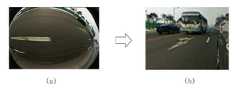
먼저, 도 3은 사이드 영상에서 후측방 영역을 뷰 변환하는 동작을 나타낸 것이다. 도 3을 참조하면, 정보 제공 장치는 (a)와 같은 사이드 카메라 영상이 입력되면, 기 설정된 값에 따라 사이드 카메라 영상에서 지정된 후측방 영역을 검출한다. 이때, 정보 제공 장치는 검출된 후측방 영역의 영상을 뷰 변환하여 (b)와 같은 후측방 영역의 뷰 변환 영상을 생성한다.First, FIG. 3 shows an operation of performing a view conversion of a rear side region in a side image. Referring to FIG. 3, when the side camera image as shown in (a) is input, the information providing apparatus detects a side area designated in the side camera image according to a predetermined value. At this time, the information providing apparatus generates a view conversion image of the rear side area as shown in (b) by performing a view conversion of the image of the side area after the detection.
여기서, 도 3의 (a)는 초광각의 영상, 예를 들어, 190° 초광각의 영상에서 검출된 후측방 영역의 영상을 더 좁은 각의 영상, 예를 들어, 60° 협각의 영상으로 뷰 변환하도록 한다.Here, FIG. 3 (a) is a view showing an image of an ultra-wide angle, for example, an image of a 190-degree ultra-wide angle, so as to transform the image of the lateral area into a narrower angle image, for example, do.
이로써, (b)와 같은 후측방 영역의 뷰 변환 영상은 물체의 형상이 선명해지게 되며, 후측방 영역의 뷰 변환 영상으로부터 보다 정확한 물체의 위치를 검출할 수 있게 된다.Thus, the shape of the object in the view conversion image of the rear side area as shown in (b) becomes clear, and the position of the object can be more accurately detected from the view conversion image of the rear side area.
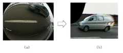
한편, 도 4는 사이드 카메라 영상에서 사이드 영역을 뷰 변환하는 동작을 나타낸 것이다. 도 4를 참조하면, 정보 제공 장치는 (a)와 같은 사이드 카메라 영상이 입력되면, 기 설정된 값에 따라 사이드 카메라 영상에서 지정된 사이드 영역을 검출한다. 이때, 정보 제공 장치는 검출된 사이드 영역의 영상을 뷰 변환하여 (b)와 같은 사이드 영역의 뷰 변환 영상을 생성한다.On the other hand, FIG. 4 shows an operation of performing a view conversion of the side area in the side camera image. Referring to FIG. 4, when the side camera image shown in (a) is input, the information providing apparatus detects a side area designated in the side camera image according to a predetermined value. At this time, the information providing apparatus generates a view conversion image of the side area as shown in (b) by performing a view conversion of the image of the detected side area.
여기서, 도 4의 (a)는 초광각의 영상, 예를 들어, 190° 초광각의 영상에서 검출된 사이드 영역의 영상을 더 좁은 각의 영상, 예를 들어, 60° 협각의 영상으로 뷰 변환하도록 한다.4A, the image of the side region detected from the super-wide angle image, for example, the image with the 190-degree super-wide angle, is transformed into the image of the narrower angle image, for example, .
이로써, (b)와 같은 사이드 영역의 뷰 변환 영상은 물체의 형상이 선명해지게 되며, 사이드 영역의 뷰 변환 영상으로부터 보다 정확한 물체의 위치를 검출할 수 있게 된다.As a result, the view transformation image of the side area as shown in (b) becomes clearer and the position of the object can be more accurately detected from the view transformation image of the side area.
도 5는 본 발명에 따른 사각지대 정보 제공 장치의 특징점 추출 동작을 설명하는데 참조되는 예시도이다. 특히, 도 5의 (a)는 도 3에서 설명한 후측방 영역(C2)과 도 4에서 설명한 사이드 영역(C1)을 나타낸 것으로, 각 영역(C1, C2)의 영상에 대한 뷰 변환 영상은 (b) 및 (c)와 같다.FIG. 5 is an exemplary diagram for explaining a minutia point extraction operation of the apparatus for providing blind zone information according to the present invention. In particular, FIG. 5A shows the rear side area C2 and the side area C1 described in FIG. 4, and the view conversion image for the image of each of the areas C1 and C2 is (b ) And (c).
이때, 정보 제공 장치는 도 5의 (b) 및 (c)와 같은 뷰 변환 영상에서 사이드 영역 및 후측방 영역에 위치한 물체의 특징점을 추출하고, 추출된 특징점으로부터 차량 등을 검출한다.At this time, the information providing apparatus extracts the feature points of the objects located in the side region and the back side region in the view transformation image as shown in FIGS. 5B and 5C, and detects the vehicles from the extracted feature points.
상기와 같이 구성되는 본 발명에 따른 차량의 사각지대 정보 제공 장치의 동작 흐름을 보다 상세히 설명하면 다음과 같다.The operation flow of the blind zone information providing apparatus according to the present invention will be described in more detail as follows.
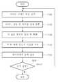
도 6은 본 발명에 따른 차량의 사각지대 정보 제공 방법에 대한 동작 흐름을 도시한 순서도이다. 도 6을 참조하면, 본 발명에 따른 정보 제공 장치는, 차량의 측면에 구비된 카메라로부터 사이드 카메라 영상이 입력되면(S100), 입력된 사이드 카메라 영상 내에서 지정된 사이드 영역 및 후측방 영역을 검출한다(S120).6 is a flowchart showing an operation flow for a method of providing blind zone information of a vehicle according to the present invention. Referring to FIG. 6, when a side camera image is input from a camera provided on a side of a vehicle (S100), a side region and a back side region specified in the input side camera image are detected (S120).
이때, 정보 제공 장치는 'S120' 과정에서 검출된 각 검출 영역의 영상을 뷰 변환하도록 한다(S130). 'S130' 과정에서 뷰 변환하는 동작에 대한 구체적인 설명은 도 3 및 도 4의 실시예를 참조하도록 한다.At this time, the information providing apparatus performs a view conversion of the image of each detection region detected in the process of 'S120' (S130). Referring to the embodiment of FIG. 3 and FIG. 4, a detailed description of the operation of converting the view in the process of 'S130' will be made.
한편, 정보 제공 장치는 'S130' 과정에서 생성된 각각의 뷰 변환영상, 즉, 사이드 영역에 대한 뷰 변환영상과 후측방 영역에 대한 뷰 변환영상으로부터 각각 특징점을 추출하고(S140), 'S140' 과정에서 추출된 특징점으로부터 사각지대의 물체, 예를 들어, 차량 또는 사람 등을 검출한다(S150).In step S140, the information providing device extracts feature points from each of the view transformation images generated in step S130, i.e., the view transformation image for the side area and the view transformation image for the back side area, An object of a dead zone, for example, a vehicle or a person, is detected from feature points extracted in the process (S150).
여기서, 'S150' 과정은, 예를 들어, 차량에 대한 특징점이 사전에 정의되고, 'S140' 과정에서 추출된 특징점과 기 정의된 차량의 특징점을 비교하여 서로 일치하면 사각지대에 위치한 차량을 검출할 수 있게 된다.Here, the 'S150' process is a process for detecting a vehicle located in a blind spot if the minutiae points of the vehicle are defined in advance and the minutiae points extracted in the 'S140' process are compared with the minutiae points of the predefined vehicle. .
이와 같이, 정보 제공 장치는 'S100' 내지 'S150' 과정을 통해 차량의 사이드 영역 및 후측방 영역, 특히 사각지대에 위치한 물체를 용이하게 검출할 수 있으며, 'S100' 내지 'S150' 과정은 별도의 동작 종료 명령이 입력되기 이전까지 반복해서 수행하도록 한다. 만일, 사각지대의 정보 제공 동작에 대한 동작 종료 명령이 입력되면(S160), 정보 제공 장치는 관련 동작을 종료하도록 한다.As described above, the information providing apparatus can easily detect an object located in a side region and a rear side region of the vehicle, in particular, a blind spot through steps S100 to S150, and steps S100 to S150 are separately performed Is repeatedly executed until the operation end command of the command is input. If the operation termination command for the information providing operation of the blind zone is inputted (S160), the information providing apparatus terminates the related operation.
이상과 같이 본 발명에 의한 차량의 사각지대 정보 제공 장치 및 방법은 예시된 도면을 참조로 설명하였으나, 본 명세서에 개시된 실시예와 도면에 의해 본 발명은 한정되지 않고, 기술사상이 보호되는 범위 이내에서 응용될 수 있다.Although the present invention has been described with reference to exemplary embodiments, it is to be understood that the invention is not limited to the disclosed exemplary embodiments and drawings, . ≪ / RTI >
10: 차량11, 11a, 11b: 카메라
100: 사각지대 정보 제공 장치
120: 뷰 변환 영역 검출부130: 뷰 변환부
131: 제1 뷰 변환부135: 제2 뷰 변환부
140: 특징점 추출부150: 검출부
C1: 사이드 영역C2: 후측방 영역10:
100: Blind zone information providing device
120: view conversion area detecting unit 130: view conversion unit
131: First view conversion unit 135: Second view conversion unit
140: feature point extracting unit 150:
C1: side region C2: rear side region
Claims (14)
Translated fromKorean상기 사이드 영역 및 상기 후측방 영역의 영상을 기 설정된 뷰 변환 파라미터에 따라 뷰 변환하여 상기 사이드 영역 및 상기 후측방 영역의 영상에 대응하는 뷰 변환 영상을 생성하는 뷰 변환부를 포함하고,
상기 뷰 변환 파라미터는 상기 사이드 카메라에 대한 카메라 캘리브레이션을 통해 추출되는 것을 특징으로 하는 차량의 사각지대 정보 제공 장치.A view conversion area detecting unit for detecting a predefined side area and a back side area from a photographed image photographed by a side camera that photographs an image including a blind spot of a vehicle; And
And a view conversion unit for generating a view conversion image corresponding to an image of the side area and the back side area by performing a view conversion of the image of the side area and the back side area according to predetermined view conversion parameters,
Wherein the view conversion parameter is extracted through camera calibration for the side camera.
상기 뷰 변환부는,
상기 뷰 변환 파라미터의 값이 룩업 테이블(Look up table)에 정의되어, 상기 룩업 테이블에 정의된 상기 뷰 변환 파라미터의 값에 따라 상기 사이드 영역 및 상기 후측방 영역의 영상을 각각 뷰 변환하는 것을 특징으로 하는 차량의 사각지대 정보 제공 장치.The method according to claim 1,
The view converter may further include:
The values of the view conversion parameters are defined in a lookup table and the images of the side area and the back side area are respectively subjected to view conversion according to the value of the view conversion parameter defined in the lookup table The information on the blind zone information of the vehicle.
상기 사이드 카메라는 초광각 카메라이고,
상기 뷰 변환부는 초광각의 촬영 영상을 촬영각 보다 더 좁은 각의 영상으로 뷰 변환하는 것을 특징으로 하는 차량의 사각지대 정보 제공 장치.The method according to claim 1,
The side camera is an ultra-wide angle camera,
Wherein the view conversion unit converts the super wide-angle photographing image into an angle image narrower than the photographing angle.
상기 뷰 변환부는,
상기 사이드 영역의 영상을 제1 뷰 변환 파라미터로 뷰 변환하여 제1 뷰 변환영상을 생성하는 제1 뷰 변환부; 및
상기 후측방 영역의 영상을 제2 뷰 변환 파라미터로 뷰 변환하여 제2 뷰 변환영상을 생성하는 제2 뷰 변환부를 포함하는 것을 특징으로 하는 차량의 사각지대 정보 제공 장치.The method of claim 3,
The view converter may further include:
A first view transformation unit for transforming the image of the side area into a first view transformation parameter to generate a first view transformation image; And
And a second view conversion unit for generating a second view conversion image by performing a view conversion of the image of the rear side area into a second view conversion parameter.
상기 뷰 변환 영상으로부터 특징점을 추출하는 특징점 추출부; 및
상기 뷰 변환 영상으로부터 추출된 특징점에 근거하여 상기 사각지대의 물체를 검출하는 검출부를 더 포함하는 것을 특징으로 하는 차량의 사각지대 정보 제공 장치.The method according to claim 1,
A feature point extraction unit for extracting feature points from the view transformation image; And
And a detector for detecting an object in the blind spot based on the feature point extracted from the view-transformed image.
상기 검출부는,
상기 뷰 변환 영상으로부터 추출된 특징점과 기 저장된 차량의 특징점을 비교하여, 비교 결과에 따라 상기 사각지대에 위치한 차량을 검출하는 것을 특징으로 하는 사각지대 정보 제공 장치.The method of claim 5,
Wherein:
And comparing the minutiae extracted from the view-converted image with minutiae points of the pre-stored vehicle, and detecting the vehicle located in the blind spot according to the comparison result.
상기 차량의 특징점은,
상기 차량의 전면, 측면, 하단 및 바퀴의 형상과 상기 차량의 모션 정보 중 적어도 하나를 포함하는 것을 특징으로 하는 사각지대 정보 제공 장치.The method of claim 6,
The minutiae of the vehicle,
Wherein the information includes at least one of a front surface, a side surface, a bottom surface of the vehicle, a shape of a wheel, and motion information of the vehicle.
상기 사이드 영역 및 상기 후측방 영역의 영상을 기 설정된 뷰 변환 파라미터에 따라 뷰 변환하여 상기 사이드 영역 및 상기 후측방 영역의 영상에 대응하는 뷰 변환 영상을 생성하는 단계를 포함하고,
상기 뷰 변환 파라미터는 상기 사이드 카메라에 대한 카메라 캘리브레이션을 통해 추출되는 것을 특징으로 하는 차량의 사각지대 정보 제공 방법.Detecting a side region and a rear side region that are predefined from a photographed image taken by a side camera that photographs an image including a blind spot of the vehicle; And
And generating a view transformation image corresponding to an image of the side region and the rear side region by performing a view transformation of the image of the side region and the rear side region according to predetermined view transformation parameters,
Wherein the view conversion parameter is extracted through camera calibration for the side camera.
상기 뷰 변환 영상을 생성하는 단계는,
상기 뷰 변환 파라미터의 값이 룩업 테이블(Look up table)에 정의되어, 상기 룩업 테이블에 정의된 상기 뷰 변환 파라미터의 값에 따라 상기 사이드 영역 및 상기 후측방 영역의 영상을 각각 뷰 변환하는 것을 특징으로 하는 차량의 사각지대 정보 제공 방법.The method of claim 8,
Wherein the generating the view transformation image comprises:
Wherein the value of the view conversion parameter is defined in a lookup table and the image of the side area and the back side area is respectively subjected to view conversion according to the value of the view conversion parameter defined in the lookup table A method of providing blind spot information of a vehicle.
상기 사이드 카메라는 광각 또는 초광각 카메라이고,
상기 뷰 변환 영상을 생성하는 단계는, 초광각의 촬영 영상을 협각의 영상으로 뷰 변환하는 것을 특징으로 하는 차량의 사각지대 정보 제공 방법.The method of claim 8,
The side camera is a wide angle or super wide angle camera,
Wherein the step of generating the view transformation image comprises the step of transforming the superposed image into an image of a narrow angle.
상기 뷰 변환 영상을 생성하는 단계는,
상기 사이드 영역의 영상을 제1 뷰 변환 파라미터로 뷰 변환하여 제1 뷰 변환영상을 생성하는 단계; 및
상기 후측방 영역의 영상을 제2 뷰 변환 파라미터로 뷰 변환하여 제2 뷰 변환영상을 생성하는 단계를 포함하는 것을 특징으로 하는 차량의 사각지대 정보 제공 방법.The method of claim 10,
Wherein the generating the view transformation image comprises:
Transforming an image of the side area into a first view transformation parameter to generate a first view transformation image; And
Converting the image of the rear side area into a second view conversion parameter to generate a second view conversion image.
상기 뷰 변환 영상으로부터 특징점을 추출하는 단계; 및
상기 뷰 변환 영상으로부터 추출된 특징점에 근거하여 상기 사각지대의 물체를 검출하는 단계를 포함하는 것을 특징으로 하는 차량의 사각지대 정보 제공 방법.The method of claim 8,
Extracting feature points from the view transformed image; And
And detecting an object in the blind spot based on the minutiae extracted from the view transformed image.
상기 사각지대의 물체를 검출하는 단계는,
상기 뷰 변환 영상으로부터 추출된 특징점과 기 저장된 차량의 특징점을 비교하여, 비교 결과에 따라 상기 사각지대에 위치한 차량을 검출하는 것을 특징으로 하는 사각지대 정보 제공 방법.The method of claim 12,
The step of detecting an object in the blind spot includes:
And comparing the minutiae extracted from the view-converted image with minutiae points of the pre-stored car, and detecting the vehicle located in the blind spot according to the comparison result.
상기 차량의 특징점은,
상기 차량의 전면, 측면, 하단 및 바퀴의 형상과 상기 차량의 모션 정보 중 적어도 하나를 포함하는 것을 특징으로 하는 사각지대 정보 제공 방법.14. The method of claim 13,
The minutiae of the vehicle,
Wherein the information includes at least one of a front surface, a side surface, a bottom surface of the vehicle, a shape of a wheel, and motion information of the vehicle.
Priority Applications (3)
| Application Number | Priority Date | Filing Date | Title |
|---|---|---|---|
| KR1020120144896AKR101449160B1 (en) | 2012-12-12 | 2012-12-12 | Apparatus and method for providing information of blind spot |
| US13/858,530US20140160289A1 (en) | 2012-12-12 | 2013-04-08 | Apparatus and method for providing information of blind spot |
| CN201310145318.4ACN103863190A (en) | 2012-12-12 | 2013-04-24 | Apparatus and method for providing information of blind spot |
Applications Claiming Priority (1)
| Application Number | Priority Date | Filing Date | Title |
|---|---|---|---|
| KR1020120144896AKR101449160B1 (en) | 2012-12-12 | 2012-12-12 | Apparatus and method for providing information of blind spot |
Publications (2)
| Publication Number | Publication Date |
|---|---|
| KR20140076415A KR20140076415A (en) | 2014-06-20 |
| KR101449160B1true KR101449160B1 (en) | 2014-10-08 |
Family
ID=50880550
Family Applications (1)
| Application Number | Title | Priority Date | Filing Date |
|---|---|---|---|
| KR1020120144896AExpired - Fee RelatedKR101449160B1 (en) | 2012-12-12 | 2012-12-12 | Apparatus and method for providing information of blind spot |
Country Status (3)
| Country | Link |
|---|---|
| US (1) | US20140160289A1 (en) |
| KR (1) | KR101449160B1 (en) |
| CN (1) | CN103863190A (en) |
Cited By (2)
| Publication number | Priority date | Publication date | Assignee | Title |
|---|---|---|---|---|
| KR20200084470A (en) | 2018-12-27 | 2020-07-13 | 주식회사 아이에이 | Intelligent side view camera system |
| US10764510B2 (en) | 2017-05-08 | 2020-09-01 | Hyundai Motor Company | Image conversion device |
Families Citing this family (9)
| Publication number | Priority date | Publication date | Assignee | Title |
|---|---|---|---|---|
| DE102014109062A1 (en)* | 2014-06-27 | 2015-12-31 | Connaught Electronics Ltd. | Method for tracking a target vehicle approaching a motor vehicle by means of a camera system of the motor vehicle, camera system and motor vehicle |
| KR102239014B1 (en)* | 2014-11-10 | 2021-04-13 | 현대모비스 주식회사 | System and method for alarm controlling of dead angle zone |
| GB201608886D0 (en)* | 2016-05-20 | 2016-07-06 | Nokia Technologies Oy | Virtual reality display |
| KR20180060753A (en)* | 2016-11-29 | 2018-06-07 | 주식회사 와이즈오토모티브 | Apparatus and method for supporting driving of vehicle |
| JP6954749B2 (en)* | 2017-03-03 | 2021-10-27 | 株式会社Soken | Adhesion detection device |
| KR102265796B1 (en)* | 2017-06-15 | 2021-06-17 | 한국전자통신연구원 | Apparatus and method tracking blind spot vehicle |
| CN108764115B (en)* | 2018-05-24 | 2021-12-14 | 东北大学 | A method of truck hazard warning |
| KR102044098B1 (en)* | 2018-05-30 | 2019-11-12 | 주식회사 와이즈오토모티브 | Apparatus and method for calibrating blind spot detection |
| US10970878B2 (en)* | 2018-12-13 | 2021-04-06 | Lyft, Inc. | Camera calibration using reference map |
Family Cites Families (7)
| Publication number | Priority date | Publication date | Assignee | Title |
|---|---|---|---|---|
| JP2006311272A (en)* | 2005-04-28 | 2006-11-09 | Denso Corp | Video display device for vehicle |
| JP2008187564A (en)* | 2007-01-31 | 2008-08-14 | Sanyo Electric Co Ltd | Camera calibration apparatus and method, and vehicle |
| US8694195B2 (en)* | 2007-12-04 | 2014-04-08 | Volkswagen Ag | Motor vehicle having a wheel-view camera and method for controlling a wheel-view camera system |
| JP2010183170A (en)* | 2009-02-03 | 2010-08-19 | Denso Corp | Display apparatus for vehicle |
| EP2512134B1 (en)* | 2009-12-07 | 2020-02-05 | Clarion Co., Ltd. | Vehicle periphery monitoring system |
| CN103237685B (en)* | 2010-12-30 | 2017-06-13 | 明智汽车公司 | Blind area display device and method |
| CN102632839B (en)* | 2011-02-15 | 2015-04-01 | 香港生产力促进局 | A vehicle blind spot early warning system and method based on rear view image cognition |
- 2012
- 2012-12-12KRKR1020120144896Apatent/KR101449160B1/ennot_activeExpired - Fee Related
- 2013
- 2013-04-08USUS13/858,530patent/US20140160289A1/ennot_activeAbandoned
- 2013-04-24CNCN201310145318.4Apatent/CN103863190A/enactivePending
Cited By (2)
| Publication number | Priority date | Publication date | Assignee | Title |
|---|---|---|---|---|
| US10764510B2 (en) | 2017-05-08 | 2020-09-01 | Hyundai Motor Company | Image conversion device |
| KR20200084470A (en) | 2018-12-27 | 2020-07-13 | 주식회사 아이에이 | Intelligent side view camera system |
Also Published As
| Publication number | Publication date |
|---|---|
| US20140160289A1 (en) | 2014-06-12 |
| KR20140076415A (en) | 2014-06-20 |
| CN103863190A (en) | 2014-06-18 |
Similar Documents
| Publication | Publication Date | Title |
|---|---|---|
| KR101449160B1 (en) | Apparatus and method for providing information of blind spot | |
| US9378553B2 (en) | Stereo image processing device for vehicle | |
| JP6795027B2 (en) | Information processing equipment, object recognition equipment, device control systems, moving objects, image processing methods and programs | |
| KR101243108B1 (en) | Apparatus and method for displaying rear image of vehicle | |
| JP6614247B2 (en) | Image processing apparatus, object recognition apparatus, device control system, image processing method and program | |
| JP6565188B2 (en) | Parallax value deriving apparatus, device control system, moving body, robot, parallax value deriving method, and program | |
| US20150341629A1 (en) | Automatic calibration of extrinsic and intrinsic camera parameters for surround-view camera system | |
| JP2008039491A (en) | Stereo image processing device | |
| JP6970577B2 (en) | Peripheral monitoring device and peripheral monitoring method | |
| JP6516012B2 (en) | Image processing apparatus, object recognition apparatus, device control system, image processing method and program | |
| JP6035620B2 (en) | On-vehicle stereo camera system and calibration method thereof | |
| JP6793608B2 (en) | Stereo image processing device | |
| JP6337504B2 (en) | Image processing apparatus, moving body, robot, device control method and program | |
| JP7278846B2 (en) | OBJECT POSITION DETECTION DEVICE, TRIP CONTROL SYSTEM, AND TRIP CONTROL METHOD | |
| JP6817780B2 (en) | Distance measuring device and control method of range measuring device | |
| WO2017094300A1 (en) | Image processing device, object recognition device, device conrol system, image processing method, and program | |
| US20180276844A1 (en) | Position or orientation estimation apparatus, position or orientation estimation method, and driving assist device | |
| KR20150101806A (en) | System and Method for Monitoring Around View using the Grid Pattern Automatic recognition | |
| JP5539250B2 (en) | Approaching object detection device and approaching object detection method | |
| JP6617150B2 (en) | Object detection method and object detection apparatus | |
| JP6543935B2 (en) | PARALLEL VALUE DERIVING DEVICE, DEVICE CONTROL SYSTEM, MOBILE OBJECT, ROBOT, PARALLEL VALUE DERIVING METHOD, AND PROGRAM | |
| JP2012252501A (en) | Traveling path recognition device and traveling path recognition program | |
| JPWO2017099199A1 (en) | Image processing apparatus, object recognition apparatus, device control system, image processing method and program | |
| CN105691300A (en) | Monitoring method and apparatus using a camera | |
| WO2011016257A1 (en) | Distance calculation device for vehicle |
Legal Events
| Date | Code | Title | Description |
|---|---|---|---|
| A201 | Request for examination | ||
| PA0109 | Patent application | St.27 status event code:A-0-1-A10-A12-nap-PA0109 | |
| PA0201 | Request for examination | St.27 status event code:A-1-2-D10-D11-exm-PA0201 | |
| PN2301 | Change of applicant | St.27 status event code:A-3-3-R10-R13-asn-PN2301 St.27 status event code:A-3-3-R10-R11-asn-PN2301 | |
| E902 | Notification of reason for refusal | ||
| PE0902 | Notice of grounds for rejection | St.27 status event code:A-1-2-D10-D21-exm-PE0902 | |
| P11-X000 | Amendment of application requested | St.27 status event code:A-2-2-P10-P11-nap-X000 | |
| P13-X000 | Application amended | St.27 status event code:A-2-2-P10-P13-nap-X000 | |
| PG1501 | Laying open of application | St.27 status event code:A-1-1-Q10-Q12-nap-PG1501 | |
| E701 | Decision to grant or registration of patent right | ||
| PE0701 | Decision of registration | St.27 status event code:A-1-2-D10-D22-exm-PE0701 | |
| GRNT | Written decision to grant | ||
| PR0701 | Registration of establishment | St.27 status event code:A-2-4-F10-F11-exm-PR0701 | |
| PR1002 | Payment of registration fee | St.27 status event code:A-2-2-U10-U11-oth-PR1002 Fee payment year number:1 | |
| PG1601 | Publication of registration | St.27 status event code:A-4-4-Q10-Q13-nap-PG1601 | |
| R18-X000 | Changes to party contact information recorded | St.27 status event code:A-5-5-R10-R18-oth-X000 | |
| PR1001 | Payment of annual fee | St.27 status event code:A-4-4-U10-U11-oth-PR1001 Fee payment year number:4 | |
| FPAY | Annual fee payment | Payment date:20180928 Year of fee payment:5 | |
| PR1001 | Payment of annual fee | St.27 status event code:A-4-4-U10-U11-oth-PR1001 Fee payment year number:5 | |
| R18-X000 | Changes to party contact information recorded | St.27 status event code:A-5-5-R10-R18-oth-X000 | |
| FPAY | Annual fee payment | Payment date:20190926 Year of fee payment:6 | |
| PR1001 | Payment of annual fee | St.27 status event code:A-4-4-U10-U11-oth-PR1001 Fee payment year number:6 | |
| PR1001 | Payment of annual fee | St.27 status event code:A-4-4-U10-U11-oth-PR1001 Fee payment year number:7 | |
| PR1001 | Payment of annual fee | St.27 status event code:A-4-4-U10-U11-oth-PR1001 Fee payment year number:8 | |
| PC1903 | Unpaid annual fee | St.27 status event code:A-4-4-U10-U13-oth-PC1903 Not in force date:20221002 Payment event data comment text:Termination Category : DEFAULT_OF_REGISTRATION_FEE | |
| PC1903 | Unpaid annual fee | St.27 status event code:N-4-6-H10-H13-oth-PC1903 Ip right cessation event data comment text:Termination Category : DEFAULT_OF_REGISTRATION_FEE Not in force date:20221002 |