KR101448312B1 - Fuel vent valve and improvement thereof - Google Patents
Fuel vent valve and improvement thereofDownload PDFInfo
- Publication number
- KR101448312B1 KR101448312B1KR1020087027817AKR20087027817AKR101448312B1KR 101448312 B1KR101448312 B1KR 101448312B1KR 1020087027817 AKR1020087027817 AKR 1020087027817AKR 20087027817 AKR20087027817 AKR 20087027817AKR 101448312 B1KR101448312 B1KR 101448312B1
- Authority
- KR
- South Korea
- Prior art keywords
- valve
- port
- auxiliary
- main
- housing
- Prior art date
- Legal status (The legal status is an assumption and is not a legal conclusion. Google has not performed a legal analysis and makes no representation as to the accuracy of the status listed.)
- Active
Links
Images


Classifications
- B—PERFORMING OPERATIONS; TRANSPORTING
- B60—VEHICLES IN GENERAL
- B60K—ARRANGEMENT OR MOUNTING OF PROPULSION UNITS OR OF TRANSMISSIONS IN VEHICLES; ARRANGEMENT OR MOUNTING OF PLURAL DIVERSE PRIME-MOVERS IN VEHICLES; AUXILIARY DRIVES FOR VEHICLES; INSTRUMENTATION OR DASHBOARDS FOR VEHICLES; ARRANGEMENTS IN CONNECTION WITH COOLING, AIR INTAKE, GAS EXHAUST OR FUEL SUPPLY OF PROPULSION UNITS IN VEHICLES
- B60K15/00—Arrangement in connection with fuel supply of combustion engines or other fuel consuming energy converters, e.g. fuel cells; Mounting or construction of fuel tanks
- B60K15/03—Fuel tanks
- F—MECHANICAL ENGINEERING; LIGHTING; HEATING; WEAPONS; BLASTING
- F16—ENGINEERING ELEMENTS AND UNITS; GENERAL MEASURES FOR PRODUCING AND MAINTAINING EFFECTIVE FUNCTIONING OF MACHINES OR INSTALLATIONS; THERMAL INSULATION IN GENERAL
- F16K—VALVES; TAPS; COCKS; ACTUATING-FLOATS; DEVICES FOR VENTING OR AERATING
- F16K24/00—Devices, e.g. valves, for venting or aerating enclosures
- F16K24/04—Devices, e.g. valves, for venting or aerating enclosures for venting only
- F16K24/042—Devices, e.g. valves, for venting or aerating enclosures for venting only actuated by a float
- F—MECHANICAL ENGINEERING; LIGHTING; HEATING; WEAPONS; BLASTING
- F16—ENGINEERING ELEMENTS AND UNITS; GENERAL MEASURES FOR PRODUCING AND MAINTAINING EFFECTIVE FUNCTIONING OF MACHINES OR INSTALLATIONS; THERMAL INSULATION IN GENERAL
- F16K—VALVES; TAPS; COCKS; ACTUATING-FLOATS; DEVICES FOR VENTING OR AERATING
- F16K31/00—Actuating devices; Operating means; Releasing devices
- F16K31/12—Actuating devices; Operating means; Releasing devices actuated by fluid
- F16K31/18—Actuating devices; Operating means; Releasing devices actuated by fluid actuated by a float
- F16K31/20—Actuating devices; Operating means; Releasing devices actuated by fluid actuated by a float actuating a lift valve
- F16K31/22—Actuating devices; Operating means; Releasing devices actuated by fluid actuated by a float actuating a lift valve with the float rigidly connected to the valve
- Y—GENERAL TAGGING OF NEW TECHNOLOGICAL DEVELOPMENTS; GENERAL TAGGING OF CROSS-SECTIONAL TECHNOLOGIES SPANNING OVER SEVERAL SECTIONS OF THE IPC; TECHNICAL SUBJECTS COVERED BY FORMER USPC CROSS-REFERENCE ART COLLECTIONS [XRACs] AND DIGESTS
- Y10—TECHNICAL SUBJECTS COVERED BY FORMER USPC
- Y10T—TECHNICAL SUBJECTS COVERED BY FORMER US CLASSIFICATION
- Y10T137/00—Fluid handling
- Y10T137/0318—Processes
- Y10T137/0402—Cleaning, repairing, or assembling
- Y10T137/0491—Valve or valve element assembling, disassembling, or replacing
- Y10T137/053—Float valve
Landscapes
- Engineering & Computer Science (AREA)
- General Engineering & Computer Science (AREA)
- Mechanical Engineering (AREA)
- Life Sciences & Earth Sciences (AREA)
- Sustainable Development (AREA)
- Sustainable Energy (AREA)
- Chemical & Material Sciences (AREA)
- Combustion & Propulsion (AREA)
- Transportation (AREA)
- Cooling, Air Intake And Gas Exhaust, And Fuel Tank Arrangements In Propulsion Units (AREA)
- Self-Closing Valves And Venting Or Aerating Valves (AREA)
Abstract
Translated fromKoreanDescription
Translated fromKorean본 발명은 롤오버 통기밸브(rollover vent valves)의 개량에 관한 것으로서, 특히 고압/저압 릴리프 밸브 및 체크 밸브로서의 기능을 하는 양방향 밸브를 구비하는 롤오버 통기밸브에 관한 것이다.The present invention relates to the improvement of rollover vent valves, and more particularly to a rollover vent valve having a high-pressure / low-pressure relief valve and a bidirectional valve serving as a check valve.
차량의 연료 시스템에는 통상 연료탱크가 설치되고, 이 연료탱크에는 연료 이송 라인에 의해 연료 레일 및 엔진의 인젝터에 접속되는 연료펌프 모듈 및 연료와 연료 증기의 유동을 조절하기 위해 제공된 다수의 밸브 수단이 연결되어 있다.The fuel system of the vehicle is usually provided with a fuel tank which is provided with a fuel pump module connected to the fuel rail and an injector of the engine by a fuel transfer line and a plurality of valve means provided for controlling the flow of fuel and fuel vapor It is connected.
이들 밸브 중의 하나는 롤오버 통기밸브로서, 이것은 한편으로 차량의 연료탱크 내의 연료 증기를 대기로 통기시키거나 또는 탄소 캐니스터와 같은 증기 회수 시스템으로 통기시키고, 다른 한편으로 특정의 조건 하에서 밸브를 확실하게 폐쇄시켜주도록 설계되어 있다. 상기 특정의 조건은 연료탱크의 과도한 충만에 기인되어 연료가 상기 롤오버 밸브를 통과하는 경우 또는 예를 들면 차량 및 연료탱크가 전복(rollover)되는 경우와 같은 탱크의 급작스런 위치변화에 기인되어 연료가 개방되어 있는 밸브를 통해 탱크의 외부로 누출되는 경우에 발생할 수 있다.One of these valves is a rollover vent valve, which on the one hand allows the fuel vapors in the vehicle's fuel tank to vent to the atmosphere or to a vapor recovery system such as a carbon canister and, on the other hand, . This particular condition is caused by the excessive filling of the fuel tank, which is caused by a sudden change in the position of the tank, such as when the fuel passes through the rollover valve or when, for example, the vehicle and the fuel tank are rolled, This can occur if the valve leaks out of the tank through the valve.
연료의 액위가 강하하거나 차량 및 그 연료탱크가 정상 위치로 복귀하는 경우에 밸브를 확실하게 개방해 주는 것은 중요하다. 따라서, 통기출구가 크면 클수 록 밸브에 작용하는 차압(differential pressure)도 커지고, 그 결과 밸브에 가해지는 폐쇄력도 더 커진다.It is important to reliably open the valve when fuel level drops or when the vehicle and its fuel tank return to their normal position. Therefore, when the vent outlet is large, the differential pressure acting on the large valve becomes large, and as a result, the closing force exerted on the valve becomes larger.
이와 같은 롤오버 밸브는 일반적으로 공지된 것으로서, 예를 들면, 특히 미국특허 US 5,738,132에는 유체 입구 및 유체 출구를 구비하는 하우징을 포함하는 롤오버 밸브가 개시되어 있다. 상기 유체 출구는 하우징의 밸브 시이트에 의해 둘러싸여 있는 실질적으로 길다란 슬릿형상의 출구를 포함한다. 또, 상기 하우징 내에 위치되고, 상기 하우징 내의 유입구 및 유출구의 사이에서 축방향 변위가 가능한 플로우트 부재; 일단부가 상기 유출구에 인접한 플로우트 부재의 일단부에 고정되고, 일부가 상기 유출구에 대해 어긋나있는 기다란 가요성 폐쇄 멤브레인 스트립(closure membrane strip); 상기 하우징 내에 배치되고, 상기 플로우트 부재를 유출구의 방향으로 가압하도록 상기 플로우트 부재 상에 지지되는 스프링 수단이 더 제공되어 있고, 여기서, 상기 스프링력과 플로우트 부재에 가해지는 부력의 합력은 상기 멤브레인 스트립을 가압하여 유출구에 대해 시일 결합시키고, 한편 상기 플로우트 부재에 가해지는 중력은 플로우트 부재를 유출구로부터 이격시킴으로써 멤브레인 스트립이 유출구와의 시일 결합상태로부터 점진적으로 분리되도록 한다.Such a rollover valve is generally known, for example, in particular US 5,738,132 discloses a rollover valve that includes a housing with a fluid inlet and a fluid outlet. The fluid outlet includes a substantially elongated slit-shaped outlet surrounded by a valve seat of the housing. A float member positioned within the housing and capable of axial displacement between an inlet and an outlet in the housing; An elongate flexible closure membrane strip having one end fixed to one end of the float member adjacent the outlet and a portion offset relative to the outlet; A spring means disposed in the housing and supported on the float member to urge the float member in the direction of the outlet, wherein the sum of the spring force and the buoyant force exerted on the float member causes the membrane strip Pressurizes and seals against the outlet while the gravity exerted on the float member causes the float member to be spaced from the outlet so that the membrane strip is gradually separated from the sealing engagement with the outlet.
더욱, 기후가 고온인 지역에서 연료탱크 시스템 내의 연료는 동작 후 구동이 중단되었을 때 팽창한다. 내연기관의 경우, 연료탱크에 접속되는 연료 공급 라인 내에서 연료가 팽창하면 연료 공급 라인의 내압이 상승하고, 그 결과 연료의 누출 또는 엔진의 작동 불량이 발생한다. 다른 한편, 기후가 저온인 지역에서는 연료가 소모되는 중에 연료탱크의 내압이 하강하고, 그 결과 연료탱크가 변형되거나 균열 이 발생한다.Moreover, in regions where the climate is hot, the fuel in the fuel tank system expands when the drive is stopped after operation. In the case of an internal combustion engine, when the fuel expands in the fuel supply line connected to the fuel tank, the internal pressure of the fuel supply line rises, resulting in leakage of fuel or malfunction of the engine. On the other hand, in regions where the climate is low, the internal pressure of the fuel tank falls while the fuel is consumed, and as a result, the fuel tank is deformed or cracked.
연료탱크로부터 엔진을 향해 비교적 높은 유동 속도로 연료를 공급함과 동시에 연료탱크 내의 진공을 방지하기 위해 연료탱크의 통기가 가능하도록 구성된 연료 시스템에 대한 요구가 존재한다.There is a need for a fuel system configured to be able to ventilate a fuel tank to supply fuel at a relatively high flow rate from the fuel tank to the engine while preventing vacuum in the fuel tank.
따라서, 종래에 다양한 유형의 체크 밸브를 연료 밸브 및 연료 처리 장치(탄소 캐니스터) 또는 연료 시스템의 기타의 부품들의 사이의 라인 내에 설치하는 것이 제안되었다.Thus, it has been proposed in the past to install various types of check valves in the line between the fuel valve and the fuel processor (carbon canister) or other components of the fuel system.
본 발명의 목적은 롤오버 통기밸브와 이중 체크밸브를 일체화함으로써 공간효율, 제조비용, 설치비용 및 노동력 등에서 장점을 제공하는 개량된 롤오버 통기밸브를 제공하는 것이다.It is an object of the present invention to provide an improved rollover vent valve that integrates a rollover vent valve and a double check valve to provide advantages in terms of space efficiency, manufacturing cost, installation cost, and labor power.
발명의 요약SUMMARY OF THE INVENTION
본 발명에 따르면, 차량의 연료 시스템에 장착되도록 구성된 후술하는 바와 같이 상이한 조건에서 동작하는 연료 밸브가 제공된다. 상기 밸브는 밸브 및 압력 홀더('압력 유지 밸브')로서 작용하는 더블 체크 밸브의 결합체이고, 따라서 공간, 제조, 조립, 설치 비용이 절약된다.According to the present invention, there is provided a fuel valve that operates in different conditions, as described below, configured to be mounted in a fuel system of a vehicle. The valve is a combination of double check valves that act as a valve and a pressure holder ('pressure retention valve'), thus saving space, manufacturing, assembly and installation costs.
본 발명에 따르면, 연료 밸브로서, 주 밸브 및 압력 반응 보조 밸브를 포함하고, 상기 주 밸브 및 압력 반응 보조 밸브는 유체 유입구, 유체 유출 포트 및 상기 주 밸브 및 압력 반응 보조 밸브의 사이에 연장되는 격벽을 포함하는 하우징 내에 수용됨과 동시에 그 하우징 내에서 변위가 가능하고; 상기 격벽은 상기 격벽의 하부면에 위치하는 주 포트 및 상기 격벽의 상부면에 위치하는 보조 포트의 사이에 연장하는 유체통로를 포함하고; 상기 주 포트는 상기 주 밸브의 시일 부재에 의해 시일될 수 있고, 상기 보조 포트는 상기 보조 밸브의 시일 부재에 의해 시일될 수 있는 연료 밸브가 제공된다.According to the present invention there is provided a fuel valve comprising a main valve and a pressure reaction assistant valve, the main valve and the pressure reaction assistant valve comprising a fluid inlet, a fluid outlet port and a partition wall extending between the main valve and the pressure reaction assistant valve And is displaceable within the housing; The partition wall includes a main port positioned on a lower surface of the partition and a fluid passage extending between auxiliary ports located on an upper surface of the partition; The main port can be sealed by the sealing member of the main valve and the auxiliary port can be sealed by the sealing member of the auxiliary valve.
본 발명의 특정 구성에 따르면, 상기 주 밸브는 롤오버 밸브이고, 상기 주 포트는 주 밸브 시이트에 의해 둘러싸여 있는 실질적으로 긴 슬릿형 개구이고; 플로우트 부재는 상기 하우징 내의 상기 유체 유입구 및 주 포트의 사이에서 축방향으로 변위될 수 있고; 상기 주 밸브의 시일 부재는 기다란 가요성 밀폐 멤브레인 스트립의 형태를 취하고, 그 스트립의 일단부는 주 포트에 인접하는 플로우트 부재의 일단부에 고정되고, 그 일부는 상기 주 포트에 대해 어긋나있고; 상기 하우징의 내부에 배치되고 상기 플로우트 부재를 주 포트의 방향으로 가압해주기 위해 상기 플로우트 부재 상에 지지되는 스프링이 더 제공된다.According to a particular configuration of the invention, said main valve is a rollover valve, said main port being a substantially long slit-shaped opening surrounded by a main valve seat; The float member being axially displaceable between the fluid inlet and the main port in the housing; Wherein the sealing member of the main valve takes the form of an elongate flexible sealing membrane strip and one end of the strip is fixed to one end of the float member adjacent to the main port and a portion thereof is offset with respect to the main port; A spring disposed within the housing and supported on the float member to urge the float member in the direction of the main port.
상기 보조 밸브는 하우징 내에서 축방향으로 변위 가능한 피스톤 부재 및 상기 유체 유출 포트로부터 상기 보조 포트를 향해 유체의 유동을 촉진시켜주는 체크 밸브로서, 상기 보조 밸브의 시일 부재에 의해 시일이 가능한 블리딩 밸브를 포함하고; 상기 피스톤은 상기 보조 포트의 시일 결합 상태로 상시 가압되고, 상기 보조 포트로부터 상기 유체 유출 포트를 향하는 방향으로 유체 유동을 촉진하도록 변위가 가능하다.The auxiliary valve includes a piston member displaceable in the housing in an axial direction and a check valve for promoting the flow of fluid from the fluid outlet port to the auxiliary port, the bleed valve being capable of being sealed by the sealing member of the auxiliary valve Include; The piston is always urged into the sealed state of the auxiliary port and is displaceable to facilitate fluid flow from the auxiliary port toward the fluid outlet port.
본 발명에 따른 밸브는 연료탱크 내의 연료의 액위에 따라 기능하고, 연료탱크 내의 압력조건의 변화에 응답하여 작용한다. 차량이 전복되거나, 급경사에 위치되어 있거나, 밸브 하우징에 연료가 유입(예를 들면, 급격한 가감속시 또는 연료의 액위가 높아진 경우)되는 경우, 주 밸브의 플로우트 부재는 주 포트의 시일 결합을 위해 변위된다.The valve according to the present invention functions according to the level of the fuel in the fuel tank and acts in response to a change in the pressure condition in the fuel tank. When the vehicle is overturned, is located at a steep slope, or when fuel enters the valve housing (for example, at a rapid acceleration / deceleration or when the fuel level of the fuel is high), the float member of the main valve Is displaced.
기타 밸브의 기능은 다음과 같이 압력차에 반응하여 작용한다.The function of other valves acts in response to the pressure difference as follows.
Ptank < Patm 이면, 보조 포트 및 주 포트가 대기에 개방되고, 연료탱크는 밸브의 유체 유출 포트로부터 밸브의 유체 유입구를 향한 유체의 유동이 가능해진다.If Ptank <Patm , the auxiliary port and main port are open to the atmosphere, and the fuel tank is allowed to flow fluid from the fluid outflow port of the valve toward the fluid inlet of the valve.
Patm< Ptank < (Patm + Pspring)이면, 보조 포트 및 블리딩 밸브는 시일상태를 유지하고, 그 결과 연료탱크 내에 소정의 압력('압력 유지 위치')이 유지된다.Patm<Ptank<(P+ Patmspring) when the auxiliary port and the bleed valve is held a sealing state, with the result that the pressure ( "pressure hold position"), predetermined in the fuel tank is maintained.
Ptank > (Patm+ Pspring)이면, 연료탱크의 연료증기압이 배출되도록 주 포트 및 보조 포트는 개방되고, 연료탱크로부터 유체 유입 포트를 향해 유체 유동이 가능해진다.Ptank (Patm+ Pspring ) , the main port and the auxiliary port are opened to allow the fluid flow from the fuel tank to the fluid inlet port so that the fuel vapor pressure of the fuel tank is discharged.
여기서:here:
Ptank는 연료탱크 내의 연료증기의 압력을 나타내고;Ptank represents the pressure of the fuel vapor in the fuel tank;
Patm는 대기압을 나타내고;Patm represents atmospheric pressure;
Pspring는 보조 밸브의 스프링 부재의 가압효과에 의해 가해지는 유효압력을 나타낸다.And Pspring represents the effective pressure applied by the pressing effect of the spring member of the auxiliary valve.
소위 압력 유지 위치에서 전형적인 압력 범위의 일례는 약 3Kpa < Ptank <4Kpa이다.An example of a typical pressure range at the so-called pressure holding position is about 3 Kpa<Ptank<4 Kpa.
상기 블리딩 밸브는 상기 피스톤 부재에 형성된 하나 이상의 개구를 포함하고, 상기 피스톤 부재에는 상기 보조 포트로부터 상기 유출 포트를 향하는 유동시 상기 하나 이상의 개구의 시일 결합을 위해 끼워진 변형이 가능한 시일 부재가 구비되고; 상기 변형이 가능한 시일 부재는 유체의 역방향 유동을 촉진하기 위해 상기 하나 이상의 개구를 개방하도록 변형된다.Wherein the bleed valve includes at least one opening formed in the piston member and wherein the piston member is provided with a deformable seal member for sealing engagement of the at least one opening in flow from the auxiliary port to the outlet port; The deformable seal member is deformed to open the at least one opening to facilitate reverse flow of the fluid.
더욱 특수한 설계에서, 상기 변형이 가능한 시일 부재는 상기 피스톤 부재의 하부면에 접합되어 상기 보조 포트의 시일 결합을 위해 작용한다.In a more specific design, the deformable seal member is bonded to the lower surface of the piston member and serves for sealing engagement of the auxiliary port.
상기 피스톤 부재는 이 피스톤 부재의 하부벽으로부터 돌출하여 상기 변형이 가능한 시일 부재를 지지하도록 끼워지는 스터드를 포함하고; 상기 스터드는 상기 피스톤 부재가 그 정상 가압 위치에 있을 때 상기 보조 포트 내에 돌출하여 상기 보조 포트와 시일 결합을 한다.The piston member including a stud which protrudes from a lower wall of the piston member and is fitted to support the deformable seal member; The stud protrudes into the auxiliary port and seals the auxiliary port when the piston member is in its normal pressure position.
더욱 특수한 설계에서, 상기 변형이 가능한 시일 부재의 외주부는 상기 보조 포트의 외주의 시일 시이트 및 상기 피스톤 부재의 하부면 사이에 클램핑되고; 상기 변형이 가능한 시일 부재의 중앙부는 상기 하나 이상의 개구의 시일/시일해제를 위해 변형이 가능하다.In a more specific design, the outer circumferential portion of the deformable seal member is clamped between the outer circumferential seal sheet and the lower surface of the piston member; The deformable center portion of the seal member is deformable for seal / seal release of the at least one opening.
이하, 본 발명 및 그 실시방법의 이해를 도모하기 위해, 첨부한 도면을 참조 하여 예시적인 실시예에 대해 설명한다.BEST MODE FOR CARRYING OUT THE INVENTION Hereinafter, exemplary embodiments will be described with reference to the accompanying drawings in order to understand the present invention and its implementation method.
도 1은 본 발명에 따른 밸브의 사시도이다.1 is a perspective view of a valve according to the present invention.
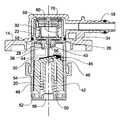
도 2는 소위 개방/통기 위치에 있는 본 발명에 따른 롤오버 밸브의 종단면도이다.2 is a longitudinal sectional view of a rollover valve according to the present invention in a so-called open / vent position;
도 3은 도 1의 밸브의 분해사시도이다.3 is an exploded perspective view of the valve of Fig.
도 4는 완전 폐쇄 위치에 있는 도 1의 롤오버 밸브의 종단면도이다.Figure 4 is a longitudinal section of the rollover valve of Figure 1 in a fully closed position;
도 5는 주 밸브가 개방되고 보조 밸브가 시일된 상태의 도 1의 롤오버 밸브의 종단면도이다.Figure 5 is a longitudinal section of the rollover valve of Figure 1 with the main valve open and the auxiliary valve sealed.
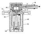
도 6은 배기 위치에 있는 도 1의 롤오버 밸브의 종단면도이다.6 is a longitudinal sectional view of the rollover valve of Fig. 1 in the exhaust position.
도 1에는 개괄적으로 참조번호 10으로 표시된 본 발명에 따른 밸브가 도시되어 있다. 이 밸브(10)는 상측의 연료탱크(도시생략)의 상면에 기밀 상태로 끼워지는 플랜지(14) 및 연료탱크의 내부 공간에 연장하는 하우징(12)을 포함한다. 플랜지(14)의 상측부분에는 탄소 캐니스터 등(도시생략)과 같은 증기 회수 시스템에 접속될 수 있는 유체 유출 포트(18)가 연장해 있다.1 shows a valve according to the invention, generally designated by the
도 2, 및 도 4 내지 도 6의 단면도 및 도 3의 사시도에서 볼 수 있는 바와 같이, 원통형 하우징(12)은 격벽(26)에 의해 상호 분할되는 하측 부분(20) 및 상측 부분(22)을 포함하고(도 5에 가장 잘 도시됨), 상기 격벽(26)에는 후술되는 바와 같이 하부 공간(30)과 상부 공간(32)의 사이에 연장하는 유동경로(28)가 형성되어 있다. 상기 하우징(20)은 플랜지(14) 내에 스냅 결합되고, O링(34)에 의해 기밀상태에 유지된다. 상기 유동경로(28)의 하단부에는 하부 공간(30) 내에 연장하는 주 포트(primary port; 38)가 형성되어 있다. 이 주 포트(38)는 주 밸브 시이트(40) 내에 형성된 기다란 슬릿형태의 개구이다.The
플로우트 부재(42)는 하부 공간(38) 내에서 축방향의 변위가 가능하고, 하우징 내에 축방향으로 연장하도록 형성됨과 동시에 플로우트에 형성된 대응하는 다수의 리세스(recesses) 내에 슬라이드 가능하게 수용되는 다수의 리브(42)에 의해 하우징 내에서 회전이 방지된다. 기다란 가요성 밀폐 멤브레인 스트립(44)은 그 일단부(46)가 플로우트 부재(42)의 상단부에 고정되고, 그 종축선에 대해 어긋나있다.The
상기 프로우트 부재(42)는 하우징의 베이스(52)에 그 하단부(50)가 지지되는 코일 스프링(48)에 의해 상방향으로 가압되고, 코일 스프링(48)의 상단부(54)는 플로우트 부재의 벽부분에 지지된다. 베이스 부재(52)에는 밸브(10)의 유체 유입구를 구성하는 다수의 개구(56)가 형성되어 있다.The
상기 기다란 가요성 폐쇄 멤브레인 스트립(44)은 지지면(45) 상에 지지되어 있고, 이 지지면(45)은 주 밸브 시이트(40)의 기다란 슬릿형태의 개구의 경사도에 대응하여 밸브의 종축선에 대해 경사를 이루고 있음을 알 수 있다.The elongate
상기 유동경로(28)의 상단부는 보조 밸브의 보조 포트를 형성하는 상부 공간(32) 내에 연장하고, 상기 보조 포트는 원주방향 돌출부(58)에 의해 형성된다.The upper end of the
상기 상부 공간(32)은 보조 밸브를 수용한다. 이 보조 밸브는 상부 공간(32) 내에서 축방향으로 변위가 가능한 피스톤 부재(62) 및 이 피스톤 부재의 하측에 환형 쇼울더(62)를 포함한다. 이 환형 쇼울더(62)에는 복수의 개구(64) 및 하나의 스 터드(stud; 66)가 형성되어 있다. 상기 스터드(66)는 이 스터드(66)에 장착되는 치수의 동축 개구(70)를 구비하는 변형이 가능한 시일 부재(68)를 유지하기 위한 것으로서, 그 결과 상기 변형이 가능한 시일 부재(68)는 스터드(66) 상에 형성된 다수의 횡방향 돌출부(72)에 의해 탈락이 방지되는 상태에서 스터드(66)를 중심으로 슬라이드 변위가 가능하다.The
상기 피스톤 부재(60)는 통상 환형 쇼울더(62)에 일단부가 지지되고, 타단부가 상부 베이스(78)에 지지됨으로써 상기 하우징의 상부 공간(32) 내에서 보조 밸브 부품을 형성하는 코일 스프링(76)에 의해 하방으로 가압된다.The
상기 하부 플로우트 부재(42)는 주 포트(38)가 완전히 개방되는 개방 위치(도 5)와 상기 주 포트(38)가 기다란 슬릿형태의 개구(40)에 기밀 상태로 지지되는 기다란 가요성 밀폐체(44)에 기인되어 시일상태가 되는 완전 폐쇄 위치(도 4)의 사이에서 변위가 가능하다. 본 명세서에 참조로 도입된 미국특허 US 5,738,132에 일예로서 공지된 소위 박리 효과(peeling effect)에 의해 상기 주 포트(38)의 시일해제(unsealing)가 발생한다. 상기 주 밸브는 차량의 전복 사고시, 또는 차량의 급격한 가감속시, 또는 연료탱크의 연료의 액위가 상승한 경우에 그 시일 위치(도 4)로 변위된다.The
상기 보조 밸브는 개구(64) 형태의 블리딩 밸브(bleeding valve)를 구비하는 이단(two stage) 체크밸브로서, 체크 밸브는 유체 출구 포트(18)로부터 보조 포트를 향해서만 유체의 유동을 촉진한다. 즉, 연료탱크 내로의 연료 유입은 허용하고(도 2), 그 반대방향으로의 유체의 유동은 방지한다.The auxiliary valve is a two stage check valve having a bleeding valve in the form of an
상기 변형이 가능한 시일 부재(68)의 주변부분은 보조 포트의 시일 시이트를 구성하는 환형 돌출부(58)의 상측에 시일 결합하도록 구성된다. 피스톤 부재(60)는 통상 코일 스프링(76) 및 대기압에 의해 하방의 시일 위치(도 2, 4 및 5) 내로 가압된다. 그 결과 피스톤(60)은 하방으로 변위됨으로써 변형이 가능한 시일 부재(68)의 외주부를 클램핑하여 보조 포트를 시일한다.The peripheral portion of the
상기 피스톤(60)은 공간(80)을 구비하는 중공체이고, 이 공간(80)은 블리딩 밸브의 개구(64)와 하우징의 상부 공간의 사이에서 연통한다.The
도 2의 위치에서, 피스톤(60)이 하향으로 변위되어 보조 포트(58)를 시일하는 경우 보조 밸브는 폐쇄된다. 그러나, 도 2에서 블리딩 밸브는 변형이 가능한 시일 부재(68)의 형성에 의해 개방됨으로써, 개구(64)를 통한 유체 유동을 유발시키고, 유출 포트(18)로부터 하우징의 상부 공간을 통해 피스톤(60)의 공간 및 개구(64)를 통해 하우징의 하부 공간(30)으로 하향하는 유체통로(28)로 유입하여 연료탱크(도시생략)로 유입된다.2, when the
그러나, 도 5의 위치에서, 보조 밸브는 시일되고, 마찬가지로 블리드 밸브는 소위 압력 유지 위치(pressure holding position)에서 시일되고, 여기서 연료탱크 내의 압력은 대기압 및 코일 스프링(76)의 가압효과를 초과하지 않게 된다.5, however, the bleed valve is likewise sealed in a so-called pressure holding position, where the pressure in the fuel tank does not exceed the atmospheric pressure and the pressure effect of the
상기 밸브는 압력 반응성 밸브로서 아래와 같은 3개의 명확한 위치에서 동작한다.The valve operates as a pressure-responsive valve in three distinct positions:
Ptank는 연료탱크 내의 연료증기의 압력을 나타내고;Ptank represents the pressure of the fuel vapor in the fuel tank;
Patm는 대기압을 나타내고;Patm represents atmospheric pressure;
Pspring는 보조 밸브의 스프링 부재의 가압효과에 의해 가해지는 유효압력을 나타낸다.And Pspring represents the effective pressure applied by the pressing effect of the spring member of the auxiliary valve.
Ptank < Patm 이면, 보조 포트 및 주 포트가 대기에 개방되고, 연료탱크는 밸브의 유체 유출 포트로부터 밸브의 유체 유입구를 향한 유체의 유동이 가능해진다(도 2).If thetank P <Patm, the auxiliary port and the main port is opened to the atmosphere, the fuel tank it is possible to flow the fluid toward the fluid inlet of the valve from the fluid outlet port of the valve (Fig. 2).
이 위치는 연료탱크 내의 압력이 대기압 이하로 강하되었을 때, 보조 밸브의 블리딩 밸브가 연료탱크 내로 공기의 유입을 촉진시켜 줌으로써 연료탱크 내에 연료탱크를 손상시킬 수 있는 감압이 발생하는 것을 방지하는 경우의 위치이다.This position prevents the bleeding valve of the auxiliary valve from accelerating the inflow of air into the fuel tank when the pressure in the fuel tank drops below the atmospheric pressure, thereby preventing the decompression which may damage the fuel tank in the fuel tank Location.
Patm< Ptank < (Patm + Pspring)이면, 보조 포트 및 블리딩 밸브는 시일상태를 유지하고, 그 결과 연료탱크 내에 소정의 압력('압력 유지 위치')이 유지된다(도 4).Patm<Ptank<If (Patm+ Pspring), a secondary port and a bleed valve is maintained at the sealing condition, and maintaining the resulting predetermined pressure ( "pressure hold position") in the fuel tank (4).
이 위치는 원리적으로 상기 위치와 유사하지만 보조 포트의 긴밀한 시일을 보장하기 위해 코일 스프링(76)의 가압 효과가 더해진다.This position is in principle similar to the above position, but the pressing effect of the
Ptank > (Patm+ Pspring)이면, 보조 포트 및 주 포트는 대기에 개방되고, 연료탱크는 밸브의 유체 유입 포트로부터 밸브의 유체 유출구를 향한 유체의 유동이 가능해진다(도 6).Ptank (Patm+ Pspring ) , the auxiliary port and the main port are open to the atmosphere, and the fuel tank is enabled to flow the fluid from the fluid inflow port of the valve toward the fluid outflow port of the valve (FIG.
이 위치는 연료탱크 내의 압력이 대기압 및 스프링(68)에 의해 가해지는 압 력을 초과함으로써 연료탱크로부터의 액체의 유출을 가속 상태로 촉진하는 경우의 위치이다.This position is the position when the pressure in the fuel tank exceeds the pressure exerted by the atmospheric pressure and the
이상, 일 실시예가 도시되고 설명되었으나, 본 발명은 이 실시예에 한정되지 않고, 첨부한 청구범위에 한정된 본 발명의 정신 및 범위 내의 모든 실시예, 개조례 및 배열들을 포함한다.While the present invention has been particularly shown and described with reference to exemplary embodiments thereof, it is to be understood that the invention is not limited to the disclosed embodiments, but, on the contrary, is intended to cover various modifications and similarities.
Claims (8)
Translated fromKoreanApplications Claiming Priority (3)
| Application Number | Priority Date | Filing Date | Title |
|---|---|---|---|
| IL175557 | 2006-05-11 | ||
| IL175557AIL175557A0 (en) | 2006-05-11 | 2006-05-11 | Fuel vent valve and improvement thereof |
| PCT/IL2007/000143WO2007132442A1 (en) | 2006-05-11 | 2007-02-04 | Fuel vent valve and improvement thereof |
Publications (2)
| Publication Number | Publication Date |
|---|---|
| KR20090018609A KR20090018609A (en) | 2009-02-20 |
| KR101448312B1true KR101448312B1 (en) | 2014-10-07 |
Family
ID=38121770
Family Applications (1)
| Application Number | Title | Priority Date | Filing Date |
|---|---|---|---|
| KR1020087027817AActiveKR101448312B1 (en) | 2006-05-11 | 2007-02-04 | Fuel vent valve and improvement thereof |
Country Status (11)
| Country | Link |
|---|---|
| US (1) | US20090071543A1 (en) |
| EP (1) | EP2016320B1 (en) |
| JP (1) | JP5043099B2 (en) |
| KR (1) | KR101448312B1 (en) |
| CN (1) | CN101427059B (en) |
| BR (1) | BRPI0709810B1 (en) |
| CA (1) | CA2645672A1 (en) |
| IL (1) | IL175557A0 (en) |
| MX (1) | MX2008012176A (en) |
| RU (1) | RU2439410C2 (en) |
| WO (1) | WO2007132442A1 (en) |
Families Citing this family (14)
| Publication number | Priority date | Publication date | Assignee | Title |
|---|---|---|---|---|
| JP5897010B2 (en) | 2010-09-02 | 2016-03-30 | ラヴァル・エー・シー・エス・リミテッド | Rollover valve |
| CN101949397A (en)* | 2010-10-20 | 2011-01-19 | 竺浩君 | Balanced valve bank of derricking cylinder system |
| CN103477135B (en)* | 2011-01-31 | 2016-01-06 | 拉瓦尔农业合作社有限公司 | Fuel valve |
| CN102734517B (en)* | 2012-07-02 | 2014-06-04 | 孙达立 | Overflow cutting valve |
| US10465634B2 (en) | 2012-08-20 | 2019-11-05 | Raval A.C.S. Ltd. | Vehicle fuel accessory |
| DE202013012312U1 (en)* | 2013-11-12 | 2016-02-24 | Veritas Ag | vent valve |
| WO2015127477A1 (en)* | 2014-02-24 | 2015-08-27 | Eaton Corporation | Fuel tank liquid vapor discriminator with integrated over-pressure and make-up air valves |
| KR101597319B1 (en)* | 2014-09-18 | 2016-02-25 | 코리아에프티 주식회사 | Valve for controlling pressure and filler tube assembly having the same |
| CN107044553A (en)* | 2017-02-23 | 2017-08-15 | 慈溪市华龙电子有限公司 | Ventilation stop valve |
| WO2021132035A1 (en)* | 2019-12-24 | 2021-07-01 | 株式会社パイオラックス | Valve device |
| GB2610754B (en)* | 2020-06-15 | 2024-12-11 | Piolax Inc | Valve device |
| RU2743312C1 (en)* | 2020-07-02 | 2021-02-17 | Акционерное общество "Российская самолетостроительная корпорация "МиГ" (АО "РСК "МиГ") | Shutoff valve of supercharging-drain line of suspended fuel tank |
| WO2022168676A1 (en)* | 2021-02-02 | 2022-08-11 | 株式会社パイオラックス | Valve device |
| KR20250123228A (en)* | 2023-01-20 | 2025-08-14 | 이턴 인텔리전트 파워 리미티드 | Fuel tank valve assembly |
Citations (4)
| Publication number | Priority date | Publication date | Assignee | Title |
|---|---|---|---|---|
| JPH08254278A (en)* | 1995-01-25 | 1996-10-01 | Raviv Precision Injection Molding | Vent valve capable of being inverted |
| JPH1047184A (en)* | 1996-07-30 | 1998-02-17 | Denso Corp | Fuel leak prevention valve |
| JP2002539384A (en)* | 1999-03-11 | 2002-11-19 | ラビブ プレシジョン インジェクション モールディング | Overfill prevention and vent and rollover valves |
| JP2003517142A (en)* | 1999-07-23 | 2003-05-20 | ラバル−アグリカルチュラル・コーオペレイティブ・ソサイエティーズ・リミテッド | Valve and method for mounting valve to tank |
Family Cites Families (22)
| Publication number | Priority date | Publication date | Assignee | Title |
|---|---|---|---|---|
| US465238A (en)* | 1891-12-15 | Toy gravity-railway | ||
| US2133575A (en)* | 1936-05-02 | 1938-10-18 | Gen Motors Corp | Pressure relief valve |
| US2506751A (en)* | 1945-11-03 | 1950-05-09 | Trask Allen | Compressor suction valve |
| GB921677A (en)* | 1960-09-12 | 1963-03-20 | Gen Motors Corp | Road vehicle suspension device |
| IT1060652B (en)* | 1976-05-20 | 1982-08-20 | Larga Spa | VALVE FOR AIR VENT FROM PLANTS OR DUCT WITH CIRCULATION OF LIQUIDS UNDER PRESSURE ESPECIALLY BOILERS OR COMPONENTS OF HEATING SYSTEMS |
| IL79587A (en)* | 1986-08-01 | 1992-09-06 | Aran Eng Dev Ltd | Fluid flow valve |
| US4753262A (en)* | 1987-02-06 | 1988-06-28 | G.T. Products, Inc. | Fuel system vent valve having roll-over closure with improved re-opening action for venting |
| US4886089A (en)* | 1988-05-27 | 1989-12-12 | Gt Development Corporation | Gas venting valve for liquid tank |
| US5027844A (en)* | 1988-10-12 | 1991-07-02 | Gt Development Corporation | Pressure and thermal relief valve for fuel tank |
| US5313978A (en)* | 1992-08-31 | 1994-05-24 | Om Industrial Co., Ltd. | Ventilation line opening/closing means of fuel tank |
| US5313977A (en)* | 1992-11-12 | 1994-05-24 | G. T. Products, Inc. | Fluid-responsive vent control valve with peel-away opening action |
| US5465857A (en)* | 1993-09-24 | 1995-11-14 | Yang; Heng-Te | Vacuum cap for liquor bottles |
| US5439023A (en)* | 1994-04-11 | 1995-08-08 | Kabushiki Kaisha Mikuni | Shut-off valve for liquid fuel |
| DE4420586C1 (en)* | 1994-06-13 | 1995-11-09 | Franz Schulte | check valve |
| US5590697A (en)* | 1994-08-24 | 1997-01-07 | G. T. Products, Inc. | Onboard vapor recovery system with two-stage shutoff valve |
| US6240950B1 (en)* | 1998-08-27 | 2001-06-05 | Stant Manufacturing Inc. | Vapor control valve with bypass circuit |
| JP3944706B2 (en)* | 2002-02-14 | 2007-07-18 | 株式会社ニフコ | 2-way valve |
| JP3973205B2 (en)* | 2002-08-07 | 2007-09-12 | 株式会社ニフコ | Fuel shut-off valve device |
| US6823850B1 (en)* | 2003-09-16 | 2004-11-30 | Daimlerchrysler Corporation | Evaporative emission system integrity module |
| JP4017587B2 (en)* | 2003-10-31 | 2007-12-05 | 株式会社パイオラックス | Check valve integrated cut valve |
| US20080142102A1 (en)* | 2006-12-18 | 2008-06-19 | Savard Raymond T | Check Valve and Pump for High Purity Fluid Handling Systems |
| JP4990020B2 (en)* | 2007-04-26 | 2012-08-01 | 株式会社ニフコ | Valve device for fuel tank |
- 2006
- 2006-05-11ILIL175557Apatent/IL175557A0/enunknown
- 2007
- 2007-02-04MXMX2008012176Apatent/MX2008012176A/ennot_activeApplication Discontinuation
- 2007-02-04CNCN2007800135011Apatent/CN101427059B/enactiveActive
- 2007-02-04KRKR1020087027817Apatent/KR101448312B1/enactiveActive
- 2007-02-04CACA 2645672patent/CA2645672A1/ennot_activeAbandoned
- 2007-02-04BRBRPI0709810-3Apatent/BRPI0709810B1/ennot_activeIP Right Cessation
- 2007-02-04JPJP2009508658Apatent/JP5043099B2/enactiveActive
- 2007-02-04WOPCT/IL2007/000143patent/WO2007132442A1/enactiveApplication Filing
- 2007-02-04USUS12/224,980patent/US20090071543A1/ennot_activeAbandoned
- 2007-02-04EPEP07706086.1Apatent/EP2016320B1/enactiveActive
- 2007-02-04RURU2008136730Apatent/RU2439410C2/enactive
Patent Citations (4)
| Publication number | Priority date | Publication date | Assignee | Title |
|---|---|---|---|---|
| JPH08254278A (en)* | 1995-01-25 | 1996-10-01 | Raviv Precision Injection Molding | Vent valve capable of being inverted |
| JPH1047184A (en)* | 1996-07-30 | 1998-02-17 | Denso Corp | Fuel leak prevention valve |
| JP2002539384A (en)* | 1999-03-11 | 2002-11-19 | ラビブ プレシジョン インジェクション モールディング | Overfill prevention and vent and rollover valves |
| JP2003517142A (en)* | 1999-07-23 | 2003-05-20 | ラバル−アグリカルチュラル・コーオペレイティブ・ソサイエティーズ・リミテッド | Valve and method for mounting valve to tank |
Also Published As
| Publication number | Publication date |
|---|---|
| BRPI0709810A8 (en) | 2018-04-24 |
| RU2008136730A (en) | 2010-06-20 |
| CA2645672A1 (en) | 2007-11-22 |
| JP2009536593A (en) | 2009-10-15 |
| JP5043099B2 (en) | 2012-10-10 |
| US20090071543A1 (en) | 2009-03-19 |
| KR20090018609A (en) | 2009-02-20 |
| IL175557A0 (en) | 2006-09-05 |
| CN101427059B (en) | 2012-05-30 |
| RU2439410C2 (en) | 2012-01-10 |
| MX2008012176A (en) | 2009-02-04 |
| BRPI0709810A2 (en) | 2011-07-26 |
| BRPI0709810B1 (en) | 2019-07-16 |
| EP2016320A1 (en) | 2009-01-21 |
| WO2007132442A1 (en) | 2007-11-22 |
| CN101427059A (en) | 2009-05-06 |
| EP2016320B1 (en) | 2015-06-10 |
Similar Documents
| Publication | Publication Date | Title |
|---|---|---|
| KR101448312B1 (en) | Fuel vent valve and improvement thereof | |
| EP0649506B1 (en) | Tank venting control assembly | |
| EP1212560B1 (en) | Valve and method for fitting it to a tank | |
| EP1782992B1 (en) | Roll-over valve with underpressure security function | |
| US7107971B2 (en) | Isolation valve useful in fuel tank emission control systems | |
| CN102165174B (en) | Pilot Operated Fuel Tank Vapor Isolation Valve | |
| JP5678346B2 (en) | Fuel vapor exhaust valve assembly | |
| JP2008524491A (en) | Steam recovery control valve | |
| JP2004183663A (en) | Vacuum operated shut-off valve, and device and method for fuel vapor vent control | |
| JP2006097674A (en) | Fuel cut-off valve | |
| US20100139625A1 (en) | Vehicle fuel system and components thereof | |
| WO2012123941A1 (en) | Fuel valve | |
| US5836341A (en) | Fuel tank vapor control apparatus | |
| US6904928B2 (en) | Vapor vent valve for fuel pump module | |
| JP2019027326A (en) | Fuel shut-off valve | |
| JP4717259B2 (en) | Pilot steam trap | |
| JPH0814115A (en) | Fuel excessive feed prevention system | |
| JPH10141164A (en) | Liquid shut-off valve device | |
| JPH109076A (en) | Fuel spill prevention valve device |
Legal Events
| Date | Code | Title | Description |
|---|---|---|---|
| PA0105 | International application | St.27 status event code:A-0-1-A10-A15-nap-PA0105 | |
| P11-X000 | Amendment of application requested | St.27 status event code:A-2-2-P10-P11-nap-X000 | |
| P13-X000 | Application amended | St.27 status event code:A-2-2-P10-P13-nap-X000 | |
| PG1501 | Laying open of application | St.27 status event code:A-1-1-Q10-Q12-nap-PG1501 | |
| A201 | Request for examination | ||
| PA0201 | Request for examination | St.27 status event code:A-1-2-D10-D11-exm-PA0201 | |
| R18-X000 | Changes to party contact information recorded | St.27 status event code:A-3-3-R10-R18-oth-X000 | |
| E902 | Notification of reason for refusal | ||
| PE0902 | Notice of grounds for rejection | St.27 status event code:A-1-2-D10-D21-exm-PE0902 | |
| P11-X000 | Amendment of application requested | St.27 status event code:A-2-2-P10-P11-nap-X000 | |
| P13-X000 | Application amended | St.27 status event code:A-2-2-P10-P13-nap-X000 | |
| PE0701 | Decision of registration | St.27 status event code:A-1-2-D10-D22-exm-PE0701 | |
| GRNT | Written decision to grant | ||
| PR0701 | Registration of establishment | St.27 status event code:A-2-4-F10-F11-exm-PR0701 | |
| PR1002 | Payment of registration fee | St.27 status event code:A-2-2-U10-U12-oth-PR1002 Fee payment year number:1 | |
| PG1601 | Publication of registration | St.27 status event code:A-4-4-Q10-Q13-nap-PG1601 | |
| FPAY | Annual fee payment | Payment date:20170912 Year of fee payment:4 | |
| PR1001 | Payment of annual fee | St.27 status event code:A-4-4-U10-U11-oth-PR1001 Fee payment year number:4 | |
| FPAY | Annual fee payment | Payment date:20180912 Year of fee payment:5 | |
| PR1001 | Payment of annual fee | St.27 status event code:A-4-4-U10-U11-oth-PR1001 Fee payment year number:5 | |
| PR1001 | Payment of annual fee | St.27 status event code:A-4-4-U10-U11-oth-PR1001 Fee payment year number:6 | |
| PR1001 | Payment of annual fee | St.27 status event code:A-4-4-U10-U11-oth-PR1001 Fee payment year number:7 | |
| PR1001 | Payment of annual fee | St.27 status event code:A-4-4-U10-U11-oth-PR1001 Fee payment year number:8 | |
| PR1001 | Payment of annual fee | St.27 status event code:A-4-4-U10-U11-oth-PR1001 Fee payment year number:9 | |
| PR1001 | Payment of annual fee | St.27 status event code:A-4-4-U10-U11-oth-PR1001 Fee payment year number:10 | |
| PR1001 | Payment of annual fee | St.27 status event code:A-4-4-U10-U11-oth-PR1001 Fee payment year number:11 | |
| PR1001 | Payment of annual fee | St.27 status event code:A-4-4-U10-U11-oth-PR1001 Fee payment year number:12 |