KR101443569B1 - System, apparatus and method for asymmetric beamforming with equal-power transmission - Google Patents
System, apparatus and method for asymmetric beamforming with equal-power transmissionDownload PDFInfo
- Publication number
- KR101443569B1 KR101443569B1KR1020087020245AKR20087020245AKR101443569B1KR 101443569 B1KR101443569 B1KR 101443569B1KR 1020087020245 AKR1020087020245 AKR 1020087020245AKR 20087020245 AKR20087020245 AKR 20087020245AKR 101443569 B1KR101443569 B1KR 101443569B1
- Authority
- KR
- South Korea
- Prior art keywords
- beamforming
- channel
- matrix
- adjusted
- transmitter
- Prior art date
- Legal status (The legal status is an assumption and is not a legal conclusion. Google has not performed a legal analysis and makes no representation as to the accuracy of the status listed.)
- Active
Links
- 238000000034methodMethods0.000titleclaimsabstractdescription69
- 230000005540biological transmissionEffects0.000titleclaimsdescription9
- 239000013598vectorSubstances0.000claimsabstractdescription26
- 238000004891communicationMethods0.000claimsabstractdescription12
- 239000011159matrix materialSubstances0.000claimsdescription71
- 238000005457optimizationMethods0.000claimsdescription23
- 238000010606normalizationMethods0.000claimsdescription9
- 238000013139quantizationMethods0.000claimsdescription8
- 230000001629suppressionEffects0.000claims6
- 238000000354decomposition reactionMethods0.000description8
- 238000010586diagramMethods0.000description1
- 238000005516engineering processMethods0.000description1
- 238000012986modificationMethods0.000description1
- 230000004048modificationEffects0.000description1
Images


Classifications
- H—ELECTRICITY
- H04—ELECTRIC COMMUNICATION TECHNIQUE
- H04L—TRANSMISSION OF DIGITAL INFORMATION, e.g. TELEGRAPHIC COMMUNICATION
- H04L27/00—Modulated-carrier systems
- H04L27/26—Systems using multi-frequency codes
- H—ELECTRICITY
- H01—ELECTRIC ELEMENTS
- H01Q—ANTENNAS, i.e. RADIO AERIALS
- H01Q3/00—Arrangements for changing or varying the orientation or the shape of the directional pattern of the waves radiated from an antenna or antenna system
- H01Q3/26—Arrangements for changing or varying the orientation or the shape of the directional pattern of the waves radiated from an antenna or antenna system varying the relative phase or relative amplitude of energisation between two or more active radiating elements; varying the distribution of energy across a radiating aperture
- H—ELECTRICITY
- H04—ELECTRIC COMMUNICATION TECHNIQUE
- H04B—TRANSMISSION
- H04B7/00—Radio transmission systems, i.e. using radiation field
- H04B7/02—Diversity systems; Multi-antenna system, i.e. transmission or reception using multiple antennas
- H—ELECTRICITY
- H04—ELECTRIC COMMUNICATION TECHNIQUE
- H04B—TRANSMISSION
- H04B7/00—Radio transmission systems, i.e. using radiation field
- H04B7/02—Diversity systems; Multi-antenna system, i.e. transmission or reception using multiple antennas
- H04B7/04—Diversity systems; Multi-antenna system, i.e. transmission or reception using multiple antennas using two or more spaced independent antennas
- H04B7/06—Diversity systems; Multi-antenna system, i.e. transmission or reception using multiple antennas using two or more spaced independent antennas at the transmitting station
- H04B7/0613—Diversity systems; Multi-antenna system, i.e. transmission or reception using multiple antennas using two or more spaced independent antennas at the transmitting station using simultaneous transmission
- H04B7/0615—Diversity systems; Multi-antenna system, i.e. transmission or reception using multiple antennas using two or more spaced independent antennas at the transmitting station using simultaneous transmission of weighted versions of same signal
- H04B7/0617—Diversity systems; Multi-antenna system, i.e. transmission or reception using multiple antennas using two or more spaced independent antennas at the transmitting station using simultaneous transmission of weighted versions of same signal for beam forming
- H—ELECTRICITY
- H04—ELECTRIC COMMUNICATION TECHNIQUE
- H04B—TRANSMISSION
- H04B7/00—Radio transmission systems, i.e. using radiation field
- H04B7/02—Diversity systems; Multi-antenna system, i.e. transmission or reception using multiple antennas
- H04B7/04—Diversity systems; Multi-antenna system, i.e. transmission or reception using multiple antennas using two or more spaced independent antennas
- H04B7/08—Diversity systems; Multi-antenna system, i.e. transmission or reception using multiple antennas using two or more spaced independent antennas at the receiving station
- H04B7/0837—Diversity systems; Multi-antenna system, i.e. transmission or reception using multiple antennas using two or more spaced independent antennas at the receiving station using pre-detection combining
- H04B7/0842—Weighted combining
- H—ELECTRICITY
- H04—ELECTRIC COMMUNICATION TECHNIQUE
- H04W—WIRELESS COMMUNICATION NETWORKS
- H04W52/00—Power management, e.g. Transmission Power Control [TPC] or power classes
- H04W52/04—Transmission power control [TPC]
- H04W52/38—TPC being performed in particular situations
- H04W52/42—TPC being performed in particular situations in systems with time, space, frequency or polarisation diversity
- H—ELECTRICITY
- H04—ELECTRIC COMMUNICATION TECHNIQUE
- H04B—TRANSMISSION
- H04B7/00—Radio transmission systems, i.e. using radiation field
- H04B7/02—Diversity systems; Multi-antenna system, i.e. transmission or reception using multiple antennas
- H04B7/04—Diversity systems; Multi-antenna system, i.e. transmission or reception using multiple antennas using two or more spaced independent antennas
- H04B7/06—Diversity systems; Multi-antenna system, i.e. transmission or reception using multiple antennas using two or more spaced independent antennas at the transmitting station
- H04B7/0613—Diversity systems; Multi-antenna system, i.e. transmission or reception using multiple antennas using two or more spaced independent antennas at the transmitting station using simultaneous transmission
- H04B7/0615—Diversity systems; Multi-antenna system, i.e. transmission or reception using multiple antennas using two or more spaced independent antennas at the transmitting station using simultaneous transmission of weighted versions of same signal
- H04B7/0619—Diversity systems; Multi-antenna system, i.e. transmission or reception using multiple antennas using two or more spaced independent antennas at the transmitting station using simultaneous transmission of weighted versions of same signal using feedback from receiving side
- H04B7/0621—Feedback content
- H04B7/0634—Antenna weights or vector/matrix coefficients
Landscapes
- Engineering & Computer Science (AREA)
- Computer Networks & Wireless Communication (AREA)
- Signal Processing (AREA)
- Mobile Radio Communication Systems (AREA)
- Radio Transmission System (AREA)
Abstract
Translated fromKoreanDescription
Translated fromKorean본 발명은 모든 안테나에 걸친 송신 전력이 동일하도록 하기위한 무선 네트워크에서 비대칭적인 빔 형성 기술에 관한 것이다.The present invention relates to asymmetric beam forming techniques in a wireless network to ensure that the transmit power across all antennas is the same.
채널 행렬의 특이 값 분해(SVD:singular-value-decomposition)를 이용하는 빔 형성 기술은 복수의 안테나가 이용 가능한 경우 성능을 향상시키기 위해 잘 알려져 있는 방법이다. 송신 및 수신 안테나의 수가 동일한 경우, 상기 빔 형성 행렬은 각각의 안테나로부터 송신된 전력이 동일하도록 하기위한 것이다. 그러나 여러 경우에서 송신 안테나(NT)의 수가 수신 안테나(NR)의 수보다 크다. 이러한 상황에서, 가장 큰 특이 값에 대응하는 고유벡터의 부분집합만을 사용한다면 안테나에 걸쳐서 동일하지 않은 전송 전력을 발생시킨다. 대부분의 송신 체인이 피크 전력이 제한되기 때문에 이러한 상황은 바람직하지 않다.A beamforming technique using singular-value-decomposition (SVD) of a channel matrix is a well known method for improving performance when multiple antennas are available. If the number of transmit and receive antennas is the same, the beamforming matrix is intended to make the power transmitted from each antenna equal. However, in many cases the number of transmit antennas NT is greater than the number of receive antennas NR. In this situation, using only a subset of the eigenvectors corresponding to the largest singular value would result in unequal transmit power across the antenna. This situation is undesirable because most transmit chains have limited peak power.
본 발명은, 비대칭 시스템에서 모든 안테나에 걸친 송신 전력이 동일하도록 하기위해 빔 형성 기술을 구현하기 위한 기술의 다수 실시예를 제공한다.The present invention provides a number of embodiments of techniques for implementing beamforming techniques to ensure that the transmit power across all antennas is the same in an asymmetric system.
복합 송신 안테나로부터 복합 수신 안테나까지의 빔 형성은 채널 다이버시티를 추출하는 잘 알려진 방법이다. 송신 안테나(NT)의 수가 수신 안테나(NR)의 수와 동일한 경우, 빔 형성을 위한 채널 행렬의 고유벡터를 사용하는 것이 최적의 전략이 되는 것으로 알려져 있다. 비대칭 상황(NT>NR)에 있어서, 통상적으로 사용된 방법은 빔 형성 벡터로서 가장 큰 고유값에 대응하는 고유벡터를 고르는 것이다. 이러한 접근이 갖는 문제점은 이것이 각각의 안테나로부터 동일하지 않은 송신 전력을 발생시킨다는 사실이다. 대부분의 경우에 상기 RF 체인이 피크-전력이 제한되기 때문에 이것은 문제가 된다.Beamforming from a complex transmit antenna to a complex receive antenna is a well known method of extracting channel diversity. It is known that using an eigenvector of the channel matrix for beamforming is an optimal strategy when the number of transmit antennas NT is equal to the number of receive antennas NR. For an asymmetric situation (NT > NR ), a commonly used method is to select an eigenvector corresponding to the largest eigenvalue as a beamforming vector. The problem with this approach is that it generates unequal transmit power from each antenna. This is a problem because in most cases the RF chain is limited in peak-power.
즉, 다수의 RF 프런트 앤드(front-ends)가 다수의 안테나를 갖는 송신기에서 사용되는 경우에, 각각의 체인이 동일한 전력을 전송하도록 하는 것이 좋은 방법이다. 이유는, 대부분의 RF 증폭기가 피크 전력에 의해 제한되어서 전체 송신 전력이 일정하도록 유지하기 위해 다른 체인의 전력을 낮추면서 하나의 체인의 전력을 상승시키는 것은 쉽지 않기 때문이다. 이것은 직교 주파수 분할 다중화(OFDM) 시스템에 대해서는 더욱 그러한데, 여기서 상기 신호는 당연히 큰 피크 대 평균 비를 가지고 RF 증폭기는 이들이 선형 범위에서 동작하도록 유지하기 위한 백-오프를 갖는다.That is, when multiple RF front-ends are used in a transmitter with multiple antennas, it is a good practice to have each chain transmit the same power. The reason is that it is not easy to raise the power of one chain while lowering the power of another chain in order to keep the total transmit power constant because most RF amplifiers are limited by peak power. This is even more so for orthogonal frequency division multiplexing (OFDM) systems where the signal naturally has a large peak-to-average ratio and the RF amplifier has a back-off to keep them operating in a linear range.
수신 안테나보다 더 많은 송신 안테나를 갖는 가장 현재에 사용되는 빔 형성 방법은 각각의 송신 체인에서 동일하지 않은 송신 전력을 갖는다. 단일 송신 스트림의 NT X 1의 경우를 위한 동일한 전력 전송의 문제점이 해소되었다(K.K. Mukkavilli, A. Sabharwal, E. Erkip 및 B. Aazhang, "On beamforming with finite rate feedback in multiple-antenna systems," IEEE Trans. Inform. Theory, vol. 49, no. 10, pp.2562--2579, Oct.2003, and D.J. Love and R.W. Heath, Jr., "Grassmanian beamforming for multiple-input multiple-output wireless systems," IEEE Trans. Inform. Theory, vol. 49, no. 10, pp. 2735--2747, Oct. 2003 참조).Most currently used beamforming methods with more transmit antennas than receive antennas have unequal transmit power in each transmit chain. The problem of equal power transmission for the case of NT X 1 of a single transmit stream has been solved (KK Mukkavilli, A. Sabharwal, E. Erkip and B. Aazhang, "On beamforming with finite rate feedback in multiple-antenna systems, &Quot; Grassmanian beamforming for multiple-input multiple-output wireless systems, "IEEE Trans. Inform. Theory, vol. 49, no. 10, pp. 2562--2579, Oct.2003, IEEE Trans. Inform. Theory, vol. 49, no. 10, pp. 2735--2747, Oct. 2003).
그러나 둘 이상의 송신 스트림을 위한 문제점은 해결되지 못했다.However, the problem for more than one transmission stream has not been solved.
본 발명은 성능에 있어서 감지할 수 있는 손실 없이 각각의 안테나에서의 송신 전력이 동일하다는 것을 보장하는 비대칭적 빔 형성을 위한 여러 실시예를 제공한다. 또한, OFDM 시스템에서의 주파수 빈보다 더 적은 빔 형성 벡터를 선택하기 위한 기술이 제공된다. 이러한 후자의 기술은 송신기가 채널 인식을 갖고 상기 벡터를 계산할 수 있다는 사실을 가정하는 것 대신에 벡터가 피드 백되는 실시예에서 유용하다.The present invention provides several embodiments for asymmetric beamforming that ensure that the transmit power at each antenna is the same without appreciable loss in performance. Techniques are also provided for selecting less beamforming vectors than frequency bins in an OFDM system. This latter technique is useful in embodiments where the vector is fed back instead of assuming that the transmitter has channel awareness and can calculate the vector.
상기 바람직한 실시예는:The preferred embodiment includes:
기술 1: 억지 기법의 정규화(brute force normalization);Technique 1: Brute force normalization;
기술 2: 오직 ±1 ±j 값으로의 양자화;Technique 2: Quantization to only ± 1 ± j values;
기술 3: 사고율 확률에 기초한 최적화;Technique 3: Optimization based on accident rate probability;
기술 4: 하이브리드 최적화;Technique 4: Hybrid optimization;
기술 5: 주파수 도메인에 걸친 최적화를Technique 5: Frequency domain optimization
포함하는 기술을 제공한다.Provides technology that includes.
본 발명은 개방 및 폐 루프 시스템에 적용되는데, 즉 상기 전자의 개방 루프 시스템은 채널의 인식을 가지고 Q를 추정하며 Q를 조정하기 위한 앞에서 기술된 기술 중 하나를 이용하는 송신기를 가지며, 상기 후자의 폐 루프 시스템은 상기 수신기가 이러한 동작을 실행하도록 만든다.The present invention applies to open and closed loop systems, that is, the open-loop system of electrons has a transmitter that uses one of the techniques described above for estimating Q and adjusting Q with the recognition of the channel, The loop system causes the receiver to perform this operation.
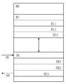
도 1은 피드백 채널을 갖는 비대칭 통신 시스템을 예시하는 도면.1 illustrates an asymmetric communication system having a feedback channel;
도 2는 본 발명에 따라서 폐 루프 비대칭 통신 시스템을 위한 빔 형성 행렬을 결정하는 방법을 도시한 도면.Figure 2 illustrates a method for determining a beamforming matrix for a closed loop asymmetric communication system in accordance with the present invention.
도 3은 비대칭 통신 시스템에서 동일한 전력을 갖는 빔 형성 행렬을 결정하고 피드백하기 위한 폐 루프 장치를 예시한 도면.3 illustrates a closed loop device for determining and feedbacking a beamforming matrix having the same power in an asymmetric communication system;
도 4는 본 발명에 따라서 수정된 비대칭 폐 루프 통신 시스템을 예시한 도면.Figure 4 illustrates a modified asymmetric closed-loop communication system in accordance with the present invention;
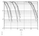
도 5는 양자화를 위한 다양한 기술의 성능을 도시한 도면.Figure 5 illustrates the performance of various techniques for quantization;
다음의 상세한 설명에서, 본 발명이 실시될 수 있는 특정 폐 루프 실시예를 오직 예로써 도시하는 첨부된 도면이 참조된다. 당업자는 이러한 실시예가 예컨대, 본 명세서에서 개시된 개별적인 구성요소의 위치 및 배열이 첨부된 청구범위에서 구체화된 바와 같이 본 발명의 정신 및 범위에서 벗어나지 않고 수정될 수 있는 것과 같이 오직 예시적이고 본 발명의 적용을 어떠한 의미로도 제한하려고 의도하지 않는다는 사실을 이해할 것이다. 즉, 상기 상세한 설명은 어떠한 제한적인 의미에서 이루어져서는 안 되고, 본 발명의 범위는 예컨대, 송신기가 Q를 추정하고 조정할 수 있는 것과 같이 첨부된 청구범위와 이의 동등물에 의해서만 한정된다. 도면에서, 유사 번호는 전체적으로 동일하거나 유사한 기능에 관한 것이다.In the following detailed description, reference is made to the accompanying drawings which show, by way of example only, a specific closed loop embodiment in which the invention may be practiced. Skilled artisans will appreciate that these embodiments are for illustrative purposes only and that the location and arrangement of the individual components disclosed herein may be modified without departing from the spirit and scope of the invention as embodied in the appended claims, The present invention is not intended to limit the scope of the present invention in any way. That is, the above detailed description should not be taken in any limiting sense, and the scope of the present invention is limited only by the appended claims and their equivalents, for example, the transmitter can estimate and adjust Q. In the drawings, like numbers refer generally to the same or like features.
본 발명은 복합 송신 안테나 빔 형성 기술과 복합 수신 안테나 결합 기술에 의해 제공되는 공간 다이버시티 이점을 획득하기 위한 복수의 저 복잡성 기술을 제공한다. 본 발명의 바람직한 실시예의 빔 형성 기술 모두는 상기 송신기에서 채널 정보를 요구한다.The present invention provides a plurality of low complexity techniques for achieving the spatial diversity benefits provided by the combined transmit antenna beam forming technique and the multiple receive antenna combining technique. All of the beamforming techniques of the preferred embodiment of the present invention require channel information at the transmitter.
도 1은 이동 스테이션{(랩탑, 퍼스널 디지털 어시스턴스(PDA)}를 포함하는 무선 근거리 영역 네트워크(WLAN)의 일부가 될 수 있고 이러한 WLAN을 위한 액세스 지점이 될 수 있는 두개의 무선 스테이션(101, 105)을 포함하는 폐 루프를 예시한다. 상기 무선 스테이션(101, 105)은 광역 무선 네트워크의 일부가 될 수 있고 무선 퍼스널 영역 네트워크이다. 이러한 스테이션(101, 105)은 가령, IEEE 802.11과 같은 무선 표준 또는 임의의 다른 표준에 따를 수 있으며, 상기 순응은 부분적이거나 완전하다. 그러나 무선 스테이션(101, 105) 각각은 복수의 안테나를 가지며, 본 발명에서 이 안테나의 수는 비대칭인 것으로 가정된다.Figure 1 illustrates two
NT 개의 송신 안테나와NR 개의 수신 안테나를 지닌 송신 빔 형성 및 수신 결합 다중-안테나 시스템(개방 및 폐 루프)이 주어지면, 거기서NR 데이터 스트림이 전송되고 빔 형성 행렬이Q로 정의되는 것으로 가정한다. 그 다음 상기 신호 모델은 다음 식으로 주어진다:Given a transmit beam forming and receive combining multi-antenna system (open and closed loop) withNT transmit antennas andNR receive antennas, where anNR data stream is transmitted and the beamforming matrix is defined asQ I suppose. The signal model is then given by:

여기서n은 노이즈 벡터이고, 상기 수신된 벡터(r)는NR X 1 벡터이고, 상기 채널 행렬(H)(103)은NRXNT행렬이고, 상기 빔 형성 행렬(Q)은NTXNR행렬이고,x는NR X 1 벡터이다. 상기 채널(H)은 완벽하게 알려진 것으로 가정된다. 상기 전송된 벡터는y=Qx인데, 이는NT X 1 벡터이다. OFDM 시스템에서, 상기 신호 모델은 각각의 주파수 빈을 위해 반복된다. 주파수 선택 채널에서,H 및Q는 각각의 주파수 빈에 대해 상이하다.Wheren is a noise vector and the received vectorr is anNRX 1 vector and the channel matrix H 103 isNRXNT Wherein the beamforming matrix (Q) isNTXNR Matrix, andx is anNRX 1 vector. The channel (H) is assumed to be perfectly known. The transmitted vector isy = Qx , which is theNTX 1 vector. In an OFDM system, the signal model is repeated for each frequency bin. In the frequency selective channel,H andQ are different for each frequency bin.
도 1에서, 폐 루프 시스템(100)이 가정되고, 현재 채널 상태 정보는 디코딩 복잡성을 줄이기 위해 스테이션(STAs)(101, 105) 사이에서 전송된다. STA 각각(101, 105)은 각각 NT(102i) 및 NR(104j)인 다수의 안테나를 포함하는데, 이들은 시스템(100)을 형성한다. 이러한 목적으로 사용되는 통신 대역폭은 "피드백 대역폭"으로 명명되고, 일부 바람직한 실시예에서 특이 값 분해(SVD)를 이용하여 결정 되는 빔 형성 행렬(Q)에 의해 현재 채널 상태 정보를 나타내는 채널 추정기(106)에 의해 추정된 이후에, 피드백 채널(107)을 통해 수신기(105)에서 송신기(101)로 피드백된다. 상기 송신기(101)는 각각의 나가는 신호를 다중 공간 채널로 전송하기 위해 빔 형성 행렬(Q)을 이용한다.1, a closed
주어진 행렬(A)의 고유벡터(P)의 행렬이 스퀘어 행렬이 아닌 경우에{(예컨대, 상기 행렬
H=USVH가 상기 채널 행렬(H)의 SVD 분해가 되도록 한다. 그 다음, Q를 위한 최적의 선택은 Q=[V1V2 ...VR]이고, 여기서 Vi는 행렬 V의 I번째 열이다. 각각의 안테나로부터 송신된 전력이 동일해야하는 요건은 상기 빔 형성 행렬(Q)의 각 행이 동일한 전력을 갖는다는 제약으로 된다. 상기 고유벡터(Vi)가 정규직교(orthonormal)이기 때문에, R=T일 경우, 전송된 벡터(v)의 각각의 구성요소는 동일한 전송된 전력을 갖는다. 그러나 R<T일 경우에는, 이것은 더 이상 사실이 아니다.Let H = USVH be the SVD decomposition of the channel matrix H. The optimal choice for Q is then Q = [V1V2 ...VR ], where Vi is the I th column of the matrix V. The requirement that the power transmitted from each antenna be the same is a constraint that each row of the beamforming matrix Q has the same power. Since R e = T, since each eigenvector Vi is orthonormal, each component of the transmitted vectorv has the same transmitted power. However, in the case of R <T, this is no longer true.
도 2는 본 발명에 따른 방법(200)을 예시한다. 단계 201에서, 상기 채널(H)이 추정된다. 바람직한 실시예에서, 수정된 채널 추정기/전력 이퀄라이저/[피드백] 장치(300)가 제공된다. 그러나 피드백이 송신기에 의해 요구되지 않는 경우에는, 수정된 채널 추정기/전력 이퀄라이저 장치만이 제공된다. 양쪽 어느 경우에, 메모리(301)는 상기 장치에 포함되고, H(301.1)는 단계 201에서 이 메모리에 저장된다. 단계 202에서, 빔 형성 행렬(Q)(301.2)이 (상기에서 설명된 바와 같이) 결정되고 상기 메모리(301)에 저장된다. 다음으로 단계 203에서 상기 빔 형성 행렬(Q)(301.2)은 다음의 기술 중 하나를 이용하여 조정되는데, 각각의 기술은 상기 송신된 벡터가 동일한 전력 성분을 갖는다는 사실을 보장하기 위해 본 발명의 분리된 바람직한 실시예를 포함한다. 상기 조정된 빔 형성 행렬(301.3)은 상기 장치(300)의 메모리(301)에 저장된다.Figure 2 illustrates a
기술 1: 억지 기법의 정규화.Technique 1: normalization of deterrent techniques.
Q=[V1V2 ...VR]로 시작한다. 그 다음, 단위 전력이 되도록 Q의 각 행을 정규화한다. 결과적인 빔 형성 행렬은v의 동일한 전력 성분을 보장한다.Q = [V1V2 ...VR ]. Then, each row of Q is normalized to be unit power. The resulting beamforming matrix ensures the same power component ofv .
기술 2: 오직 ±1 ±j 값으로의 양자화.Technique 2: Quantization to only ± 1 ± j values.
다시, 상기에서 정의된 바와 같이 Q로 시작한다. 그 다음,Q1=sign[Re(Q)+jsign(Im(Q))]는 빔형성 행렬인데, 이 행렬은 동일한 전력 성분을 가질 뿐 아니라, 각각의 성분이 4개의 값 중에서 하나만 될 수 있기 때문에, 더 적은 수의 비트가 피드백을 위해 사용되게도 한다.Again, begin with Q as defined above. Then,Q1 = sign [Re (Q) + jsign (Im (Q))] is a beamforming matrix that not only has the same power component but also can have only one of the four values , So fewer bits are used for feedback.
기술 3: 사고율 확률에 기초한 최적화.Technique 3: Optimization based on accident rate probability.
동일한 전력 행을 갖는 빔 형성 행렬을 획득하기 위한 앞서 기술한 기술은 임의의 최적성 기준을 포함하지 않는다. Q의 각 요소가 ±1 ±j 임을 가정하면서 시작한다. 그 다음, Q를 선택하기 위한 기준은 |det(HQ)|를 최대화시키는 것이다. 4NTNR의 가능성 있는 Q 행렬이 존재하기 때문에, 억지 기법의 검색은 너무 복잡해질 것이다. 바람직한 단순화는 (1)Q의 페이즈가 문제되지 않기 때문에, Q11은 1+j로 임의로 설정되고 (2)서로 직교인 이러한 열만을 검색할 수 있다는 것을 포함한다. 앞서 기술된 두개의 바람직한 단순화를 이용하면, 상기 검색 공간이 극적으로 줄어든다. 예컨대, 4 X 2의 경우에, 엔트리 ±1 ±j를 갖는 벡터에 직교인 오로지 9개의 벡터만이 존재한다. 그러므로 상기 검색 공간은 65536에서 64*9=576으로 감소한다. 이러한 방법에서, SVD가 실행될 필요가 전혀 없다.The previously described technique for obtaining a beamforming matrix having the same power row does not include any optimality criterion. Assume that each element of Q is ± 1 ± j. Then, the criterion for selecting Q is to maximize | det (HQ) |.Since there is a probable Q matrix of 4NTNR , the search for the deterrent scheme will be too complicated. The preferred simplification includes that (1) the phase of Q is not a problem, Q11 can be arbitrarily set to 1 + j and (2) search only those columns that are orthogonal to each other. Using the two preferred simplifications described above, the search space is dramatically reduced. For example, in the case of 4 X 2, there are only nine vectors that are orthogonal to the vector with entries ± 1 ± j. Therefore, the search space is reduced from 65536 to 64 * 9 = 576. In this way, there is no need for the SVD to be executed.
기술 4: 하이브리드 최적화.Technique 4: Hybrid optimization.
상기에서의 기술 3은 여전히 다수의 가능성에 걸쳐서 최적화를 요구한다. 추가적인 단순화는 제1 벡터를 위한 기술 2를 이용하고 즉, 상기 SVD 행렬의 제1 벡터를 양자화하고 그 다음, 다른 벡터를 결정하기 위해 기술 3을 이용하는 것이다. 4 X 2의 경우에 대해, 이것은 상기 SVD 실행을 요구하고, 이 다음에 9개의 가능성 있는 선택에 걸친 최적화가 후속한다.Technique 3 above still requires optimization over a number of possibilities. An additional simplification is to use technique 2 for the first vector, i. E., To quantize the first vector of the SVD matrix and then use technique 3 to determine another vector. For the case of 4 X 2, this requires the SVD implementation, followed by optimization over the nine possible choices.
기술 5: 주파수 도메인에 걸친 최적화.Technique 5: Optimization across the frequency domain.
단일 빔 형성 행렬이 p 개의 채널 주파수 빈을 위해 선택되는 경우에, 상기 최적화 기준은
지금부터 도 2를 참고하면, 수신기(105)를 포함하는 폐 루프에서 빔 형성 행렬(Q)을 결정하고 송신기(101)로 Q를 피드백하기 위한 방법이 예시된다. 단계 201에서 상기 수신기는 행렬(H)에서 채널 상태를 추정한다. 그 다음, 단계 202에서 빔 형성 행렬(Q)은 (상기에서 설명된 바와 같이) H로부터 추정된다. 단계 203에서, 본 발명의 기술 1 내지 5 중 임의의 기술은 성분이 동일한 전력을 갖고 단계 204에서 조정 빔 형성 행렬이 송신기에 피드백되도록 하기 위해 상기 행렬(Q)을 조정하도록 사용된다.Referring now to FIG. 2, a method for determining a beamforming matrix Q in a closed loop including a
도 3은 본 발명에 따른 채널 상태 행렬(H)과 관련된 데이터(301.1), 초기 빔 형성 행렬과 관련된 데이터(301.2) 및 상기 조정 빔 형성 행렬과 관련된 데이터를 저장하기 위한 메모리(301)를 포함하는 본 발명에 따른 폐 루프에서 채널 추정과 피드백을 위한 장치(300)를 예시한다. 상기 장치(300)는 채널(H)을 위한 수신된 신호(303)를 받아들이는 전력 이퀄라이저 구성요소(302)를 더 포함하고, 채널 추정기 모듈(302.1)로부터 채널 행렬(H)을 생성하고 채널 상태 행렬/데이터(301.1)로서 메 모리(301)에 이를 저장하기 위해 채널 추정기 모듈(302.1)을 포함한다. 상기 전력 이퀄라이저 구성요소(302)는 초기 빔 형성 행렬을 형성하는 빔 형성 행렬 조정 모듈(302.2)을 더 포함하고 본 발명의 기술 1 내지 5 중 미리 선택된 하나의 기술에 따른 초기 빔 형성 행렬을 조정하고(203), 상기 조정된 행렬(Q)과 관련된 데이터를 조정된 빔 형성 행렬/데이터(301.3)로 상기 메모리(301)에 저장한다. 마지막으로, 상기 전력 이퀄라이저 구성요소는 상기 송신기(101)로의 피드백 채널(107)을 통해 피드백 신호(304)로서 상기 조정된 빔 형성 행렬(Q)을 피드백하는 피드백 모듈(302.3)을 포함한다.FIG. 3 includes a
도 4는 본 발명에 따라 구성된 채널 추정기/피드백 장치(300)로 인터페이스하고 채널 상태(H)(103)에 관한 송신기(101)로부터 수신된 신호(303)를 여기로 제공하도록 수정된 적어도 하나의 송신기(101)와 수신기(105)를 포함하는 폐 루프 비대칭 통신 시스템(400)을 예시한다. 상기 채널 추정기/피드백 장치(300)는 상기 채널을 추정하고 상기 채널 행렬(H) 및 관련된 데이터(301.1)를 생성하여 상기 메모리에 저장하고, 상기 채널 행렬(H)로부터의 초기 빔 형성 행렬(301.2)을 생성하여 상기 메모리에 저장하고, 본 발명의 기술 1 내지 5 중 미리 선택된 하나의 기술에 따른 초기 빔 형성 행렬을 조정하고(203) 상기 조정된 빔 형성 행렬(Q)(301.3)을 상기 메모리에 저장한다. 마지막으로, 상기 채널 추정기/피드백 장치(300)는 상기 피드백 채널(107)을 이용하여 송신기(101)에 상기 조정된 빔 형성 행렬(Q)(304)을 피드백한다(204). 위에서 보인바와 같이, 통신 시스템(400)은 가령, IEEE 802.11과 같은 임의의 통신 표준을, 완전하게 또는 부분적으로, 따를 수 있고 무선 통신 네 트워크의 임의 유형의 일부분이 될 수 있다. 본 발명은 모든 비대칭 무선 통신 네트워크/시스템에 적용되는 것으로 의도된다.4 is a block diagram of an embodiment of the present invention that interfaces with a channel estimator /
도 5는 비트-인터리브드 코디드 모듈레이션(bit-interleaved coded modulation)을 이용하는 주파수-선택 시스템에서 4 X 2 시스템을 양자화하기 위한 다양한 기술의 성능을 예시한다. 특히 더 높은 비율로(비율 5/6 64QAM) 상기 기술이 동일하지 않은 전송 전력을 갖는 최적의 빔 형성에 비교하여 볼 때 아주 작은 성능 손실을 갖는다는 사실을 알 수 있다.Figure 5 illustrates the performance of various techniques for quantizing a 4 X 2 system in a frequency-selective system using bit-interleaved coded modulation. It can be seen that this technique has a very small performance loss, especially at a higher rate (
본 발명이 특정 실시예 즉, 폐 루프와 연계해서 설명되었지만, 수정 및 변형이 첨부된 청구범위에서 구체화되는 바와 같이 본 발명의 정신과 범위에서 벗어나지 않고 이루어질 수 있음을 당업자가 깨달을 것이라는 사실을 이해해야 한다. 특히, 상기 송신기는 채널의 인식을 갖고 상기 수신기로부터 임의의 피드백을 요구하지 않고 상기 방법을 실행할 수 있다.While the present invention has been described in connection with a particular embodiment, that is, a closed loop, it should be understood that modifications and variations will occur to those skilled in the art, without departing from the spirit and scope of the invention as embodied in the appended claims. In particular, the transmitter may have the knowledge of the channel and perform the method without requiring any feedback from the receiver.
상술한 바와 같이, 본 발명은 모든 안테나를 통한 송신 전력이 동일하도록 하기위한 무선 네트워크에서 비대칭적인 빔 형성 기술에 이용가능 하다.As described above, the present invention is available for asymmetric beamforming techniques in wireless networks to ensure that the transmit power across all antennas is the same.
Claims (16)
Translated fromKoreanApplications Claiming Priority (5)
| Application Number | Priority Date | Filing Date | Title |
|---|---|---|---|
| US77558906P | 2006-02-22 | 2006-02-22 | |
| US60/775589 | 2006-02-22 | ||
| US80947406P | 2006-05-30 | 2006-05-30 | |
| US60/809474 | 2006-05-30 | ||
| PCT/IB2007/050546WO2007096820A1 (en) | 2006-02-22 | 2007-02-20 | System, apparatus, and method for asymmetrical beamforming with equal-power transmissions |
Publications (2)
| Publication Number | Publication Date |
|---|---|
| KR20080098037A KR20080098037A (en) | 2008-11-06 |
| KR101443569B1true KR101443569B1 (en) | 2014-09-23 |
Family
ID=38137586
Family Applications (1)
| Application Number | Title | Priority Date | Filing Date |
|---|---|---|---|
| KR1020087020245AActiveKR101443569B1 (en) | 2006-02-22 | 2007-02-20 | System, apparatus and method for asymmetric beamforming with equal-power transmission |
Country Status (12)
| Country | Link |
|---|---|
| US (1) | US8190211B2 (en) |
| EP (1) | EP1989791B1 (en) |
| JP (1) | JP5210178B2 (en) |
| KR (1) | KR101443569B1 (en) |
| AR (1) | AR059861A1 (en) |
| AU (1) | AU2007219200B2 (en) |
| BR (1) | BRPI0707993B1 (en) |
| CA (1) | CA2642893C (en) |
| MY (1) | MY153443A (en) |
| RU (1) | RU2426232C2 (en) |
| TW (1) | TWI433484B (en) |
| WO (1) | WO2007096820A1 (en) |
Families Citing this family (20)
| Publication number | Priority date | Publication date | Assignee | Title |
|---|---|---|---|---|
| JP2921236B2 (en) | 1992-02-12 | 1999-07-19 | トヨタ自動車株式会社 | Shifting device for automatic transmission |
| US8130864B1 (en)* | 2007-04-03 | 2012-03-06 | Marvell International Ltd. | System and method of beamforming with reduced feedback |
| US8165543B2 (en)* | 2007-04-25 | 2012-04-24 | Marvell World Trade Ltd. | Power amplifier adjustment for transmit beamforming in multi-antenna wireless systems |
| KR101520667B1 (en) | 2007-09-10 | 2015-05-18 | 엘지전자 주식회사 | Allocation method of pilot subcarriers in mimo system |
| WO2009084877A1 (en)* | 2007-12-28 | 2009-07-09 | Samsung Electronics Co., Ltd. | Method and apparatus for transmitting/receiving downlink data in wireless communication network |
| JP5463620B2 (en) | 2008-02-26 | 2014-04-09 | 日産自動車株式会社 | Control device for shift-by-wire failure of vehicles with automatic transmission |
| US8582672B2 (en)* | 2009-02-12 | 2013-11-12 | Futurewei Technologies, Inc. | System and method for wireless communications using spatial multiplexing with incomplete channel information |
| US8644368B1 (en) | 2009-09-23 | 2014-02-04 | Marvell International Ltd. | Transparent implicit beamforming in a communication system |
| US9276722B2 (en) | 2010-05-05 | 2016-03-01 | Qualcomm Incorporated | Expanded search space for R-PDCCH in LTE-A |
| US9071286B2 (en)* | 2011-05-26 | 2015-06-30 | Cohere Technologies, Inc. | Modulation and equalization in an orthonormal time-frequency shifting communications system |
| US8917787B2 (en)* | 2011-03-22 | 2014-12-23 | Hitachi, Ltd. | Systems and methods for creating a downlink precode for communication system with per-antenna power constraints |
| EP2695335A4 (en)* | 2011-04-06 | 2014-11-26 | Sejent Corp | Measuring instantaneous bit rate in a network connection |
| US9485714B2 (en) | 2011-11-09 | 2016-11-01 | Agency For Science, Technology And Research | Addressing multiple communication terminals in a wireless communication network |
| KR101284935B1 (en) | 2012-06-20 | 2013-07-10 | 한국과학기술원 | Outage-based robust beam design method for mimo interference channel with channel uncertainty |
| US9661579B1 (en) | 2013-05-03 | 2017-05-23 | Marvell International Ltd. | Per-tone power control in OFDM |
| US9843097B1 (en) | 2013-07-08 | 2017-12-12 | Marvell International Ltd. | MIMO implicit beamforming techniques |
| US9281884B2 (en)* | 2014-04-07 | 2016-03-08 | Imagination Technologies, Llc | Reordering of a beamforming matrix |
| CN105429686B (en)* | 2015-11-05 | 2018-10-12 | 江苏中兴微通信息科技有限公司 | The molding transmitting device of the asymmetric mixed-beam of divergence type and method |
| CN105306125B (en)* | 2015-11-16 | 2018-10-16 | 江苏中兴微通信息科技有限公司 | Asymmetric shared mixed-beam is molded R-T unit |
| US11228987B2 (en)* | 2020-04-09 | 2022-01-18 | Motorola Mobility Llc | Method and wireless communication device for sharing a total power budget between at least two transmitters |
Citations (1)
| Publication number | Priority date | Publication date | Assignee | Title |
|---|---|---|---|---|
| US20060056531A1 (en) | 2004-09-10 | 2006-03-16 | Qinghua Li | Interpolation in channel state feedback |
Family Cites Families (7)
| Publication number | Priority date | Publication date | Assignee | Title |
|---|---|---|---|---|
| US5621752A (en)* | 1994-06-23 | 1997-04-15 | Qualcomm Incorporated | Adaptive sectorization in a spread spectrum communication system |
| US8634481B1 (en)* | 2000-11-16 | 2014-01-21 | Alcatel Lucent | Feedback technique for wireless systems with multiple transmit and receive antennas |
| US7813440B2 (en)* | 2003-01-31 | 2010-10-12 | Ntt Docomo, Inc. | Multiple-output multiple-input (MIMO) communication system, MIMO receiver and MIMO receiving method |
| JP4413540B2 (en)* | 2003-01-31 | 2010-02-10 | 株式会社エヌ・ティ・ティ・ドコモ | Multi-input multi-output propagation path signal transmission apparatus and receiving station |
| JP4039413B2 (en)* | 2003-11-05 | 2008-01-30 | ソニー株式会社 | Wireless communication system, wireless communication method, and wireless communication apparatus |
| US7680461B2 (en) | 2003-11-05 | 2010-03-16 | Sony Corporation | Wireless communications system, wireless communications method, and wireless communications apparatus |
| US7362822B2 (en)* | 2004-09-08 | 2008-04-22 | Intel Corporation | Recursive reduction of channel state feedback |
- 2007
- 2007-02-16TWTW096106241Apatent/TWI433484B/enactive
- 2007-02-20CACA2642893Apatent/CA2642893C/enactiveActive
- 2007-02-20WOPCT/IB2007/050546patent/WO2007096820A1/enactiveApplication Filing
- 2007-02-20BRBRPI0707993-1Apatent/BRPI0707993B1/enactiveIP Right Grant
- 2007-02-20EPEP07705922.8Apatent/EP1989791B1/enactiveActive
- 2007-02-20USUS12/280,002patent/US8190211B2/enactiveActive
- 2007-02-20KRKR1020087020245Apatent/KR101443569B1/enactiveActive
- 2007-02-20JPJP2008555922Apatent/JP5210178B2/enactiveActive
- 2007-02-20ARARP070100708Apatent/AR059861A1/enactiveIP Right Grant
- 2007-02-20RURU2008137643/09Apatent/RU2426232C2/enactive
- 2007-02-20MYMYPI20083213Apatent/MY153443A/enunknown
- 2007-02-20AUAU2007219200Apatent/AU2007219200B2/enactiveActive
Patent Citations (1)
| Publication number | Priority date | Publication date | Assignee | Title |
|---|---|---|---|---|
| US20060056531A1 (en) | 2004-09-10 | 2006-03-16 | Qinghua Li | Interpolation in channel state feedback |
Also Published As
| Publication number | Publication date |
|---|---|
| EP1989791B1 (en) | 2016-08-24 |
| AU2007219200A1 (en) | 2007-08-30 |
| BRPI0707993A2 (en) | 2011-05-17 |
| TW200742310A (en) | 2007-11-01 |
| RU2008137643A (en) | 2010-03-27 |
| US20090221241A1 (en) | 2009-09-03 |
| WO2007096820A1 (en) | 2007-08-30 |
| CA2642893A1 (en) | 2007-08-30 |
| EP1989791A1 (en) | 2008-11-12 |
| TWI433484B (en) | 2014-04-01 |
| AU2007219200B2 (en) | 2011-02-17 |
| JP2009527973A (en) | 2009-07-30 |
| BRPI0707993B1 (en) | 2020-02-18 |
| CA2642893C (en) | 2015-06-23 |
| MY153443A (en) | 2015-02-13 |
| JP5210178B2 (en) | 2013-06-12 |
| AR059861A1 (en) | 2008-05-07 |
| KR20080098037A (en) | 2008-11-06 |
| RU2426232C2 (en) | 2011-08-10 |
| US8190211B2 (en) | 2012-05-29 |
Similar Documents
| Publication | Publication Date | Title |
|---|---|---|
| KR101443569B1 (en) | System, apparatus and method for asymmetric beamforming with equal-power transmission | |
| US9444536B2 (en) | Precoding with a codebook for a wireless system | |
| EP1540830B9 (en) | System and method for multiple-input multiple-output (mimo) radio communication | |
| US20090286494A1 (en) | Iterative tree search-based precoding technique for multiuser mimo communication system | |
| CN101582712A (en) | Method for realizing precoding and method for generating precoding matrices | |
| CN101390302B (en) | System, apparatus, and method for asymmetrical beamforming with equal-power transmissions | |
| Kim et al. | Recursive covariance design for multiple antenna physical layer multicasting | |
| MX2008010756A (en) | System, apparatus, and method for asymmetrical beamforming with equal-power transmissions |
Legal Events
| Date | Code | Title | Description |
|---|---|---|---|
| PA0105 | International application | Patent event date:20080819 Patent event code:PA01051R01D Comment text:International Patent Application | |
| PG1501 | Laying open of application | ||
| A201 | Request for examination | ||
| PA0201 | Request for examination | Patent event code:PA02012R01D Patent event date:20120220 Comment text:Request for Examination of Application | |
| E902 | Notification of reason for refusal | ||
| PE0902 | Notice of grounds for rejection | Comment text:Notification of reason for refusal Patent event date:20130829 Patent event code:PE09021S01D | |
| E902 | Notification of reason for refusal | ||
| PE0902 | Notice of grounds for rejection | Comment text:Notification of reason for refusal Patent event date:20140228 Patent event code:PE09021S01D | |
| E701 | Decision to grant or registration of patent right | ||
| PE0701 | Decision of registration | Patent event code:PE07011S01D Comment text:Decision to Grant Registration Patent event date:20140822 | |
| GRNT | Written decision to grant | ||
| PR0701 | Registration of establishment | Comment text:Registration of Establishment Patent event date:20140917 Patent event code:PR07011E01D | |
| PR1002 | Payment of registration fee | Payment date:20140917 End annual number:3 Start annual number:1 | |
| PG1601 | Publication of registration | ||
| FPAY | Annual fee payment | Payment date:20170905 Year of fee payment:4 | |
| PR1001 | Payment of annual fee | Payment date:20170905 Start annual number:4 End annual number:4 | |
| FPAY | Annual fee payment | Payment date:20180905 Year of fee payment:5 | |
| PR1001 | Payment of annual fee | Payment date:20180905 Start annual number:5 End annual number:5 | |
| FPAY | Annual fee payment | Payment date:20190905 Year of fee payment:6 | |
| PR1001 | Payment of annual fee | Payment date:20190905 Start annual number:6 End annual number:6 | |
| PR1001 | Payment of annual fee | Payment date:20200908 Start annual number:7 End annual number:7 | |
| PR1001 | Payment of annual fee | Payment date:20210907 Start annual number:8 End annual number:8 | |
| PR1001 | Payment of annual fee | Payment date:20230906 Start annual number:10 End annual number:10 | |
| PR1001 | Payment of annual fee | Payment date:20240909 Start annual number:11 End annual number:11 |