KR101442548B1 - Scroll compressor - Google Patents
Scroll compressorDownload PDFInfo
- Publication number
- KR101442548B1 KR101442548B1KR1020080076687AKR20080076687AKR101442548B1KR 101442548 B1KR101442548 B1KR 101442548B1KR 1020080076687 AKR1020080076687 AKR 1020080076687AKR 20080076687 AKR20080076687 AKR 20080076687AKR 101442548 B1KR101442548 B1KR 101442548B1
- Authority
- KR
- South Korea
- Prior art keywords
- bypass
- pressure chamber
- scroll
- hole
- fixed
- Prior art date
- Legal status (The legal status is an assumption and is not a legal conclusion. Google has not performed a legal analysis and makes no representation as to the accuracy of the status listed.)
- Expired - Fee Related
Links
Images


Classifications
- F—MECHANICAL ENGINEERING; LIGHTING; HEATING; WEAPONS; BLASTING
- F04—POSITIVE - DISPLACEMENT MACHINES FOR LIQUIDS; PUMPS FOR LIQUIDS OR ELASTIC FLUIDS
- F04C—ROTARY-PISTON, OR OSCILLATING-PISTON, POSITIVE-DISPLACEMENT MACHINES FOR LIQUIDS; ROTARY-PISTON, OR OSCILLATING-PISTON, POSITIVE-DISPLACEMENT PUMPS
- F04C28/00—Control of, monitoring of, or safety arrangements for, pumps or pumping installations specially adapted for elastic fluids
- F04C28/24—Control of, monitoring of, or safety arrangements for, pumps or pumping installations specially adapted for elastic fluids characterised by using valves controlling pressure or flow rate, e.g. discharge valves or unloading valves
- F04C28/26—Control of, monitoring of, or safety arrangements for, pumps or pumping installations specially adapted for elastic fluids characterised by using valves controlling pressure or flow rate, e.g. discharge valves or unloading valves using bypass channels
- F—MECHANICAL ENGINEERING; LIGHTING; HEATING; WEAPONS; BLASTING
- F04—POSITIVE - DISPLACEMENT MACHINES FOR LIQUIDS; PUMPS FOR LIQUIDS OR ELASTIC FLUIDS
- F04C—ROTARY-PISTON, OR OSCILLATING-PISTON, POSITIVE-DISPLACEMENT MACHINES FOR LIQUIDS; ROTARY-PISTON, OR OSCILLATING-PISTON, POSITIVE-DISPLACEMENT PUMPS
- F04C18/00—Rotary-piston pumps specially adapted for elastic fluids
- F04C18/02—Rotary-piston pumps specially adapted for elastic fluids of arcuate-engagement type, i.e. with circular translatory movement of co-operating members, each member having the same number of teeth or tooth-equivalents
- F04C18/0207—Rotary-piston pumps specially adapted for elastic fluids of arcuate-engagement type, i.e. with circular translatory movement of co-operating members, each member having the same number of teeth or tooth-equivalents both members having co-operating elements in spiral form
- F04C18/0215—Rotary-piston pumps specially adapted for elastic fluids of arcuate-engagement type, i.e. with circular translatory movement of co-operating members, each member having the same number of teeth or tooth-equivalents both members having co-operating elements in spiral form where only one member is moving
- F—MECHANICAL ENGINEERING; LIGHTING; HEATING; WEAPONS; BLASTING
- F04—POSITIVE - DISPLACEMENT MACHINES FOR LIQUIDS; PUMPS FOR LIQUIDS OR ELASTIC FLUIDS
- F04C—ROTARY-PISTON, OR OSCILLATING-PISTON, POSITIVE-DISPLACEMENT MACHINES FOR LIQUIDS; ROTARY-PISTON, OR OSCILLATING-PISTON, POSITIVE-DISPLACEMENT PUMPS
- F04C23/00—Combinations of two or more pumps, each being of rotary-piston or oscillating-piston type, specially adapted for elastic fluids; Pumping installations specially adapted for elastic fluids; Multi-stage pumps specially adapted for elastic fluids
- F04C23/008—Hermetic pumps
- F—MECHANICAL ENGINEERING; LIGHTING; HEATING; WEAPONS; BLASTING
- F04—POSITIVE - DISPLACEMENT MACHINES FOR LIQUIDS; PUMPS FOR LIQUIDS OR ELASTIC FLUIDS
- F04C—ROTARY-PISTON, OR OSCILLATING-PISTON, POSITIVE-DISPLACEMENT MACHINES FOR LIQUIDS; ROTARY-PISTON, OR OSCILLATING-PISTON, POSITIVE-DISPLACEMENT PUMPS
- F04C29/00—Component parts, details or accessories of pumps or pumping installations, not provided for in groups F04C18/00 - F04C28/00
- F04C29/12—Arrangements for admission or discharge of the working fluid, e.g. constructional features of the inlet or outlet
- F04C29/124—Arrangements for admission or discharge of the working fluid, e.g. constructional features of the inlet or outlet with inlet and outlet valves specially adapted for rotary or oscillating piston pumps
- F—MECHANICAL ENGINEERING; LIGHTING; HEATING; WEAPONS; BLASTING
- F16—ENGINEERING ELEMENTS AND UNITS; GENERAL MEASURES FOR PRODUCING AND MAINTAINING EFFECTIVE FUNCTIONING OF MACHINES OR INSTALLATIONS; THERMAL INSULATION IN GENERAL
- F16K—VALVES; TAPS; COCKS; ACTUATING-FLOATS; DEVICES FOR VENTING OR AERATING
- F16K15/00—Check valves
- F16K15/02—Check valves with guided rigid valve members
- F—MECHANICAL ENGINEERING; LIGHTING; HEATING; WEAPONS; BLASTING
- F04—POSITIVE - DISPLACEMENT MACHINES FOR LIQUIDS; PUMPS FOR LIQUIDS OR ELASTIC FLUIDS
- F04C—ROTARY-PISTON, OR OSCILLATING-PISTON, POSITIVE-DISPLACEMENT MACHINES FOR LIQUIDS; ROTARY-PISTON, OR OSCILLATING-PISTON, POSITIVE-DISPLACEMENT PUMPS
- F04C2210/00—Fluid
- F04C2210/26—Refrigerants with particular properties, e.g. HFC-134a
- F—MECHANICAL ENGINEERING; LIGHTING; HEATING; WEAPONS; BLASTING
- F04—POSITIVE - DISPLACEMENT MACHINES FOR LIQUIDS; PUMPS FOR LIQUIDS OR ELASTIC FLUIDS
- F04C—ROTARY-PISTON, OR OSCILLATING-PISTON, POSITIVE-DISPLACEMENT MACHINES FOR LIQUIDS; ROTARY-PISTON, OR OSCILLATING-PISTON, POSITIVE-DISPLACEMENT PUMPS
- F04C2240/00—Components
- F04C2240/30—Casings or housings
- Y—GENERAL TAGGING OF NEW TECHNOLOGICAL DEVELOPMENTS; GENERAL TAGGING OF CROSS-SECTIONAL TECHNOLOGIES SPANNING OVER SEVERAL SECTIONS OF THE IPC; TECHNICAL SUBJECTS COVERED BY FORMER USPC CROSS-REFERENCE ART COLLECTIONS [XRACs] AND DIGESTS
- Y10—TECHNICAL SUBJECTS COVERED BY FORMER USPC
- Y10S—TECHNICAL SUBJECTS COVERED BY FORMER USPC CROSS-REFERENCE ART COLLECTIONS [XRACs] AND DIGESTS
- Y10S415/00—Rotary kinetic fluid motors or pumps
- Y—GENERAL TAGGING OF NEW TECHNOLOGICAL DEVELOPMENTS; GENERAL TAGGING OF CROSS-SECTIONAL TECHNOLOGIES SPANNING OVER SEVERAL SECTIONS OF THE IPC; TECHNICAL SUBJECTS COVERED BY FORMER USPC CROSS-REFERENCE ART COLLECTIONS [XRACs] AND DIGESTS
- Y10—TECHNICAL SUBJECTS COVERED BY FORMER USPC
- Y10S—TECHNICAL SUBJECTS COVERED BY FORMER USPC CROSS-REFERENCE ART COLLECTIONS [XRACs] AND DIGESTS
- Y10S417/00—Pumps
- Y10S417/902—Hermetically sealed motor pump unit
Landscapes
- Engineering & Computer Science (AREA)
- General Engineering & Computer Science (AREA)
- Mechanical Engineering (AREA)
- Physics & Mathematics (AREA)
- Fluid Mechanics (AREA)
- Rotary Pumps (AREA)
Abstract
Translated fromKoreanDescription
Translated fromKorean본 발명은 스크롤 압축기의 용량 가변 장치에 관한 것이다.The present invention relates to a capacity variable device of a scroll compressor.
일반적으로 스크롤 압축기는 공조기 분야에서 널리 사용되는 고효율, 저소음 압축기이다. 상기 스크롤 압축기는 두 개의 스크롤이 상대 선회운동을 하면서 양쪽 스크롤 사이에 두 개 한 쌍의 압축실이 형성되고, 상기 압축실이 지속적으로 중심방향으로 이동하면서 체적이 작아져 냉매가 연속으로 흡입 압축되어 토출되는 방식이다.Generally, scroll compressors are high-efficiency, low-noise compressors widely used in the field of air conditioners. The scroll compressor has two pairs of compression chambers formed between the two scrolls while the two scrolls rotate relative to each other. The volume of the compression chamber continuously decreases as the compression chamber moves toward the center, It is a way to be discharged.
상기 스크롤 압축기는 압축실의 중간에 바이패스홀을 형성하고 그 바이패스홀을 이용하여 중간압이 된 일부의 냉매를 흡입홈쪽으로 이동시켜 압축기의 용량을 가변시키거나, 또는 토출관과 흡입관을 연결하고 그 사이에 솔레노이드밸브를 설치하여 상기 솔레노이드밸브를 개폐동작에 의해 압축기의 용량을 가변시키는 방식이 알려져 있다.The scroll compressor has a bypass hole formed in the middle of the compression chamber, and a part of refrigerant having an intermediate pressure is moved toward the suction groove by using the bypass hole to vary the capacity of the compressor, or to connect the discharge pipe and the suction pipe And a solenoid valve is provided therebetween to vary the capacity of the compressor by opening and closing the solenoid valve.
그러나, 상기와 같은 종래의 스크롤 압축기에 있어서, 상기 바이패스홀을 이용하는 방식은 바이패스홀의 위치가 토출구를 중심으로 대칭되게 형성됨에 따라 그 바이패스홀을 개폐하기 위하여는 복수 개의 밸브가 구비되어야 하므로 생산비용이 증가할 수 있고, 비교적 먼 거리에 배치되는 복수의 바이패스홀을 동시에 제어하여야 하므로 그만큼 제어가 용이하지 않아 신뢰성이 저하될 수 있으며, 각각의 바이패스홀에서 바이패스되는 냉매의 양이 일정하지 않아 압축기의 용량 가변을 정밀하게 제어하지 못하는 문제점이 있었다. 또, 상기 토출관과 흡입관을 연결하는 방식은 배관이 복잡하고 그 배관에 밸브를 설치하여야 하므로 그만큼 압축기의 크기가 커져야 하고 조립공수의 증가로 인해 생산비용이 증가하는 문제점이 있었다.However, in the conventional scroll compressor as described above, since the position of the bypass hole is symmetrical about the discharge port in the method using the bypass hole, a plurality of valves must be provided in order to open and close the bypass hole Since the number of bypass holes arranged at relatively long distances must be controlled at the same time, the control can not be easily performed and the reliability may be deteriorated, and the amount of refrigerant bypassed in each bypass hole The variable capacity of the compressor can not be precisely controlled. In addition, there is a problem in that the discharge pipe and the suction pipe are connected with each other because the piping is complicated and the valve is required to be installed in the pipeline, thereby increasing the size of the compressor and increasing the production cost due to an increase in the number of assemblies.
본 발명은 상기와 같은 종래 스크롤 압축기가 가지는 문제점을 해결한 것으로, 바이패스홀을 이용하여 압축기의 용량을 가변하면서도 이를 제어하기 위한 밸브의 개수를 줄일 수 있고 신뢰도를 높일 수 있으며 바이패스되는 냉매의 양을 일정하게 하여 압축기의 용량을 정밀하게 제어할 수 있고 배관을 간소화하여 압축기를 소형화하면서 생산비용을 절감할 수 있는 스크롤 압축기를 제공하려는데 본 발명의 목적이 있다.The present invention solves the above-mentioned problems of the conventional scroll compressor. It is possible to reduce the number of valves for controlling the capacity of the compressor while using the bypass hole, and to increase the reliability of the compressor. It is an object of the present invention to provide a scroll compressor capable of precisely controlling the capacity of a compressor with a constant amount and simplifying piping to reduce the size of the compressor while reducing the production cost.
본 발명의 목적을 해결하기 위하여, 밀폐용기; 상기 밀폐용기의 내부에 고정 설치되고 나선형의 고정랩이 형성되는 고정스크롤; 및 상기 고정스크롤의 고정랩에 맞물려 상대운동을 하면서 두 개 한 쌍의 압축실을 이루도록 나선형의 선회랩이 형성되는 선회스크롤;을 포함하고, 상기 고정스크롤에는 압축실의 안쪽에서 바깥쪽으로 연통되는 적어도 한 개 이상의 바이패스홀이 형성되고, 상기 바이패스홀의 출구측에는 그 바이패스홀의 단면적보다 넓은 단면적을 가지도록 중간압 챔버가 형성되며, 상기 중간압 챔버에는 상기 바이패스홀을 개폐하는 체크밸브가 설치되는 스크롤 압축기가 제공된다.In order to solve the object of the present invention, A fixed scroll fixedly installed in the closed container and having a spiral fixed lap; And an orbiting scroll having a helical orbiting wrap formed to form a pair of two compression chambers while engaging with the fixed lap of the fixed scroll, wherein the fixed scroll is provided with at least An intermediate pressure chamber is formed in the outlet side of the bypass hole so as to have a cross sectional area wider than a cross sectional area of the bypass hole. A check valve for opening and closing the bypass hole is installed in the intermediate pressure chamber A scroll compressor is provided.
본 발명에 의한 스크롤 압축기는, 상기 고정스크롤에 압축실에서 압축되는 냉매의 일부를 바이패스시키는 복수 개의 바이패스홀을 형성하고 그 복수 개의 바 이패스홀의 출구단이 서로 연통되도록 하는 중간압 챔버를 상기 고정스크롤의 상면에 형성하며 상기 중간압 챔버의 출구에 한 개의 바이패스밸브를 설치함으로써 용량가변장치를 간소화하고 이를 통해 압축기를 소형화하면서 생산비용을 절감할 수 있다. 또, 복수 개의 바이패스홀이 중간압 챔버에 서로 연통되도록 배치됨에 따라 복수 개의 바이패스홀을 한 개의 바이패스밸브만으로도 용이하게 제어할 수 있고, 이를 통해 상기 바이패스밸브의 개수를 줄여 생산비용을 절감할 수 있을 뿐만 아니라 한 개의 바이패스밸브로 용량을 가변할 수 있어 제어를 용이하면서도 정확하게 할 수 있다. 또, 상기 바이패스홀에 체크밸브를 설치하여 상기 스크롤 압축기의 용량을 가변하는 과정에서 사체적이 발생되는 것을 미연에 방지하여 압축기 성능을 높일 수 있다.The scroll compressor according to the present invention is characterized in that a plurality of bypass holes for bypassing a part of the refrigerant compressed in the compression chamber are formed in the fixed scroll and an intermediate pressure chamber for allowing the outlet ends of the plurality of bypass holes to communicate with each other, The bypass valve is provided at the outlet of the intermediate pressure chamber to simplify the capacity variable device and to reduce the production cost by downsizing the compressor. In addition, since the plurality of bypass holes are arranged to communicate with the intermediate pressure chamber, a plurality of bypass holes can be easily controlled by only one bypass valve, thereby reducing the number of bypass valves, Not only can it be saved, but also the capacity can be changed by one bypass valve, so that the control can be performed easily and accurately. In addition, by providing a check valve in the bypass hole, it is possible to prevent the occurrence of carcass in the process of varying the capacity of the scroll compressor, thereby improving the performance of the compressor.
이하, 본 발명에 의한 스크롤 압축기를 첨부도면에 도시된 실시예에 의거하여 상세하게 설명한다.Hereinafter, the scroll compressor according to the present invention will be described in detail with reference to the embodiments shown in the accompanying drawings.
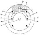
도 1에 도시된 바와 같이, 본 발명에 의한 스크롤 압축기는, 가스흡입관(SP)과 가스토출관(DP)이 구비되는 밀폐용기(10)와, 상기 밀폐용기(10) 내부의 상하 양측에 각각 고정되는 메인프레임(20) 및 서브프레임(30)과, 상기 메인프레임(20)과 서브프레임(30) 사이에 장착되어 회전력이 발생되도록 하는 구동모터(40)와, 상기 메인프레임(20)의 상면에 고정 설치되는 고정스크롤(50)과, 상기 고정스크롤(50)에 맞물려 2개 한 쌍의 압축실(P)이 형성되도록 상기 메인프레임(20)의 상면에 선회 가능하게 얹히는 선회스크롤(60)과, 상기 선회스크롤(60)과 메인프레임(20)의 사이 에 설치되어 상기 선회스크롤(60)의 자전을 방지하면서 선회시키는 올담링(Oldham's ring)(70)과, 상기 고정스크롤(50)에 설치되어 후술할 바이패스홀을 개폐하는 체크밸브(80)와, 상기 메인프레임(20)의 일측에 설치되어 압축기 운전모드를 가변시키는 바이패스밸브(90)를 포함한다.1, a scroll compressor according to the present invention includes a closed container 10 having a gas suction pipe SP and a gas discharge pipe DP, A driving
상기 밀폐용기(10)은 상기 구동모터(40)를 설치하는 원통용기(11)와, 상기 원통용기(11)의 상하 양측에 결합되는 상부캡(12)과 하부캡(13)으로 이루어진다. 상기 원통용기(11)에 상기 가스흡입관(SP)이 결합되고, 상기 상부캡(12)에 상기 가스흡입관(SP)이 밀폐용기(10)의 길이방향에 대해 대략 수직한 방향으로 결합된다. 상기 가스토출관(DP)은 상부캡(12)을 관통하여 토출공간(S2)에 연통되도록 결합된다.The closed container 10 includes a
도 1에서와 같이 상기 고정스크롤(50)은 나선형으로 형성되는 선회스크롤의 선회랩과 맞물려 두 개 한 쌍의 압축실을 이루도록 나선형의 고정랩(51)이 형성되고, 상기 고정랩(51)의 외곽측에 흡입홈(52)이 형성되며, 상기 고정랩(51)의 중앙측에 토출구(53)가 형성된다. 상기 고정랩(51)은 양쪽 압축실(P)이 동시에 형성될 수 있도록 그 고정랩(51)의 감긴방향 길이가 후술할 선회랩(61)의 감긴방향 길이와 거의 동일하게 형성될 수 있으나, 경우에 따라서는 선회랩(61)의 감긴방향 길이와 대략 180°의 위상차만큼 길거나 짧게 형성될 수도 있다.As shown in FIG. 1, the
그리고 상기 고정랩(51)의 중간, 즉 중간측 고정랩 사이의 경판부에는 상기 압축실(P)의 안쪽에서 바깥쪽으로 연통되도록 복수 개의 바이패스홀(54)이 원주방향을 따라 등간격으로 형성되고, 상기 바이패스홀들(54)의 출구, 즉 상기 고정스크 롤(50)의 상면에는 원호모양의 중간압 챔버(55)가 소정의 깊이로 음각지게 형성된다. 상기 바이패스홀들(54)은 상기 중간압 챔버에 함께 수용되도록 형성된다. 상기 바이패스홀들(54)은 원주방향을 따라 등간격으로 형성될 수도 있으나, 양쪽 압축실(P)에 각각 연통될 수 있도록 상기 선회스크롤(60)의 궤적을 따라 대략 180°의 위상차를 두고 형성될 수도 있다. 상기 바이패스홀들(54)은 원형단면 형상의 구멍으로 형성될 수도 있고, 도 2에서와 같이 원호단면 형상의 장공으로 형성될 수도 있다. 그외 다른 형상으로도 형성될 수 있다.A plurality of
그리고 상기 고정스크롤(50)의 상면에는 상기 원호모양의 중간압 챔버(55)를 복개하도록 하는 덮개판(56)이 설치된다. 상기 덮개판(56)은 도 2에서와 같이 원판모양으로 형성될 수도 있고 상기 중간압 챔버(55)를 덮을 수 있을 정도의 원호형 또는 환형으로 형성될 수도 있다.A cover plate (56) for covering the arc-shaped intermediate pressure chamber (55) is provided on the upper surface of the fixed scroll (50). The
상기 체크밸브(80)는 각각의 바이패스홀들(54)에 대응되도록 복수 개가 구비될 수 있다. 예컨대, 도 2 및 도 3에서와 같이 상기 체크밸브들(80)은 그 일단이 상기 고정스크롤(50)의 상면, 즉 상기 중간압 챔버(55)를 이루는 상면에 고정되고 그 타단이 자유단을 이루면서 상기 바이패스홀들(54)을 개폐하는 복수 개의 밸브(81)와, 상기 복수 개의 밸브(81)의 압축배면에 설치되어 각각의 밸브들(81)의 열림량을 제한하는 복수 개의 리테이너들(82)로 이루어진다.A plurality of the
그리고 도 2 및 도 3에서와 같이 상기 고정스크롤(50)의 가장자리에는 상기 중간압 챔버(55)의 외주면 또는 저면에서 상기 고정스크롤(50)을 관통하여 상기 밀폐용기(10)의 흡입공간(S1)에 연통되도록 한 개의 연통구멍(58)이 형성되고, 상기 연통구멍(58)의 중간에는 반경방향으로 관통되고 상기 바이패스밸브(80)가 장착되어 그 바이패스밸브(80)가 상기 연통구멍(58)을 개폐하도록 하는 밸브구멍(59)이 형성된다. 상기 연통구멍(58)은 한 개만 형성하는 것이 바이패스밸브(80)의 개수를 줄일 수 있어 바람직하나 경우에 따라서는 복수 개가 형성될 수도 있다.As shown in FIGS. 2 and 3, at the edge of the fixed
상기 바이패스밸브(90)는 상기 중간압 챔버(55)에서 중간압의 냉매를 상기 밀폐용기(10)의 흡입공간(S1)으로 선택적으로 바이패스시킬 수 있도록 솔레노이드밸브로 이루어진다. 즉, 상기 바이패스밸브(90)는 전원 인가시 그 개폐부(미부호)가 상기 연통구멍(58)을 개폐할 수 있도록 상기 밸브구멍(59)에 대해 삽입되어 설치된다. 그리고 상기 바이패스밸브(80)에 전원을 인가하기 위한 전원단자(미도시)는 상기 밀폐용기(10)에 설치될 수 있다.The
도면중 미설명 부호인 21은 관통구멍, 41은 고정자, 42는 회전자, 43은 구동축, 56a는 토출공, 57은 역지밸브이다.
상기와 같은 종래의 스크롤 압축기는 다음과 같이 동작된다.The conventional scroll compressor as described above operates as follows.
즉, 상기 구동모터(40)에 전원이 인가되면, 상기 구동축(43)이 회전자(42)와 함께 회전을 하면서 선회스크롤(60)이 올담링(70)에 의해 메인프레임(20)의 상면에서 편심 거리만큼 선회운동을 하게 되고, 이와 함께 상기 고정랩(51)과 선회랩(61)의 사이에는 점차 중앙으로 이동하는 2개 한 쌍의 압축실(P)이 연속하여 형성되며, 상기 압축실(P)은 선회스크롤(60)의 지속적인 선회운동에 의해 중심으로 이동하면서 체적이 감소하여 냉매가스를 흡입 압축한 후 상기 토출공간(S2)으로 토출되었다가 상기 가스토출관(DP)을 통해 냉동사이클로 토출된다.That is, when power is applied to the driving
여기서, 상기 바이패스밸브(90)를 압축기의 운전모드에 따라 작동시켜 압축기의 용량을 가변시키게 된다.Here, the
예컨대, 압축기가 세이빙모드로 작동할 때는 도 4에서와 같이 상기 바이패스밸브(90)에 전원이 인가되어 상기 바이패스밸브(90)가 연통구멍(58)을 개방하게 된다. 이에 따라 상기 체크밸브(80)가 열리면서 상기 압축실(P)의 냉매가 복수 개의 바이패스홀(54)과 중간압 챔버(55) 그리고 상기 고정스크롤(50)의 연통구멍(58)과 메인프레임의 관통구멍(21)을 통해 흡입압을 이루는 상기 밀폐용기(10)의 흡입공간(S1)으로 바이패스 되고, 이에 따라 압축기는 일을 하지 않거나 또는 파워모드 보다 적은 일을 하게 된다. 이때, 상기 체크밸브(80)의 밸브(81)는 그 압축배면의 압력이 낮아지게 되어 압축실(P)에서의 압축냉매에 밀려 열리게 된다.For example, when the compressor operates in the saving mode, power is applied to the
반면, 압축기가 파워운전모드로 작동할 때는 도 5에서와 같이 상기 바이패스밸브(80)에 전원이 인가되지 않아 상기 바이패스밸브(80)가 연통구멍(58)을 차단한 상태를 유지하게 된다. 이에 따라 상기 중간압 챔버(55)에는 중간압의 냉매가 채워진 상태를 유지하게 될 뿐 흡입압을 이루는 상기 밀폐용기(10)의 흡입공간(S1)으로 바이패스 되지 않아 압축실(P)의 냉매는 지속적으로 이동하면서 압축된다.On the other hand, when the compressor operates in the power operation mode, power is not applied to the
이때, 상기 바이패스밸브(90)가 닫힘에 따라 상기 연통구멍(58)과 중간압 챔버(55)가 밀폐된 상태를 유지하게 되고, 그 연통구멍(58)과 중간압 챔버(55)의 내부압력이 압축실(P)의 압력보다 높은 압력상태가 유지된다. 이에 따라 상기 압축실(P)에서 압축되는 냉매가 상기 중간압 챔버(55)로 누설되지 않으면서 그 중간압 챔버(55)가 사체적이 되는 것을 미연에 방지할 수 있고, 이로 인해 스크롤 압축기 의 성능이 향상될 수 있다.At this time, as the
한편, 본 발명에 의한 스크롤 압축기에서 상기 체크밸브에 대한 다른 실시예들이 있는 경우는 다음과 같다.Meanwhile, in the scroll compressor according to the present invention, other embodiments of the check valve are as follows.
먼저, 상기 체크밸브는 한 개의 일체형으로 형성될 수도 있다. 예컨대, 도 6에서와 같이 밸브(181)는 원호형으로 형성되어 상기 중간압 챔버(55)의 바닥면에 고정되는 고정부(185)와, 상기 고정부(185)의 중간, 즉 상기 바이패스홀들(54)에 대응되는 부위에 절개 형성되는 개폐부들(186)로 이루어질 수 있다. 상기 개폐부들(186)은 도 6에서와 같이 연통구멍쪽을 향해 서로 대향되게 형성되는 것이 냉매가 보다 신속하게 흡입공간으로 바이패스가 될 수 있다.First, the check valves may be integrally formed. 6, the
다음, 전술한 실시예들에서는 상기 체크밸브가 일단이 고정되는 외팔보 모양으로 형성되는 것이나, 본 실시예는 도 7 및 도 8에서와 같이 피스톤 모양으로 형성될 수 있다. 예컨대, 상기 고정스크롤(50)의 바이패스홀(54)의 출구단에는 일정 깊이의 밸브홈(54a)이 형성되고, 그 밸브홈(54a)에 상기 피스톤밸브(281)가 미끄러지면서 상기 바이패스홀(54)을 개폐하도록 삽입된다. 그리고 상기 밸브홈(54a)의 내주면에는 상기 바이패스홀(54)을 통과하는 냉매가 신속하게 중간압 챔버(55)로 누설될 수 있도록 냉매안내홈(54b)이 형성될 수 있다. 상기 냉매안내홈(54b)은 도 8에서와 같이 경사지게 형성될 수도 있으나, 피스톤의 운동방향으로 일정 깊이만큼 홈지게 형성될 수도 있다. 그리고 상기 피스톤밸브(281)의 상단에는 압축기의 운전모드가 변화될 때, 즉 세이빙모드에서 파워모드로 전환될 때 상기 피스톤밸브(280)가 신속하게 닫히도록 탄성력을 가세하기 위한 밸브스프링(282)이 설치될 수 있다. 이에 대한 작용효과는 전술한 외팔보 형태의 체크밸브와 유사하므로 구체적인 설명은 생략한다.Next, in the above-described embodiments, the check valve is formed in a cantilever shape in which one end is fixed, but the present embodiment may be formed in a piston shape as shown in FIGS. For example, a
한편, 본 발명에 의한 스크롤 압축기에 대한 다른 실시예가 있는 경우는 다음과 같다.Meanwhile, another embodiment of the scroll compressor according to the present invention is as follows.
즉, 전술한 실시예에서는 상기 고정스크롤(50)의 고정랩(51)과 선회스크롤(60)의 선회랩(61)이 대칭 형상으로 형성되는 것이었으나, 경우에 따라서는 상기 고정랩(51)과 선회랩(61)의 감긴 방향 길이가 다른, 소위 비대칭형상으로 형성될 수도 있다. 예컨대, 상기 고정스크롤(50)의 고정랩(51)은 양쪽 압축실(P)이 동시에 형성될 수 있도록 그 고정랩(51)의 감긴 방향 길이가 상기 선회랩(61)의 감긴방향 길이보다 대략 180°의 위상차를 가지도록 더 길게 형성될 수 있다. 이 경우, 상기 고정랩(51)의 중간, 즉 중간측 고정랩 사이의 경판부에는 복수 개의 바이패스홀(54)이 대략 방사상으로 동일선상에 형성되거나 또는 ±45°의 범위내에 형성될 수 있다. 이에 따라, 상기 중간압 챔버(55)는 복수의 바이패스홀(54)이 함께 수용될 수 있도록 한 개의 원형 또는 방사상의 원호형으로 형성될 수 있다. 이에 대한 다른 구성과 작용 효과는 전술한 실시예와 대동소이하므로 구체적인 설명은 생략한다.That is, although the fixed
이렇게 하여, 스크롤 압축기의 용량을 가변할 수 있어 압축기의 용량을 가변시키는 장치를 간소화할 수 있고 이를 통해 저렴하면서도 신뢰성 높은 스크롤 압축기의 용량 가변 장치를 제공할 수 있다. 또, 상기 바이패스홀에 체크밸브를 설치하여 상기 스크롤 압축기의 용량을 가변하는 과정에서 사체적이 발생되는 것을 미연 에 방지하여 압축기 성능을 높일 수 있다.In this way, the capacity of the scroll compressor can be varied to simplify the apparatus for varying the capacity of the compressor, thereby providing an inexpensive and reliable variable capacity device for the scroll compressor. In addition, by providing a check valve in the bypass hole, it is possible to prevent the occurrence of carcass in the process of varying the capacity of the scroll compressor, thereby improving the performance of the compressor.
한편, 전술한 실시예들에서는 저압식 스크롤 압축기에 관하여 살펴본 것이나, 경우에 따라서는 도 9에서와 같이 상기 밀폐용기의 내부공간이 토출압을 이루는 고압식 스크롤 압축기에서도 동일하게 적용될 수 있다. 이 경우, 상기 밀폐용기(10)의 내부공간이 토출압을 형성함에 따라 상기 바이패스밸브(80)의 전자석이 고압분위기에서는 성능에 좋지 않은 영향을 받을 수 있다. 따라서 이 경우에는 상기 고정스크롤(50)에 바이패스홀(54)과 그 바이패스홀(54)을 수용하는 중간압 챔버(55)를 형성하고, 상기 중간압 챔버(55)에 연결되어 상기 밀폐용기(10)의 외곽으로 연장되는 바이패스관(100)을 상기 가스흡입관(SP)에 연결하며, 상기 밀폐용기(10)의 외곽에서 바이패스밸브(80)가 설치되도록 할 수도 있다. 이에 대한 다른 구성과 작용 효과는 전술한 실시예들과 대동소이하므로 구체적인 설명은 생략한다. 다만, 이 경우에는 앞서 언급한 바와 같이 고온에서 신뢰성이 낮은 전자밸브를 바이패스밸브로 사용하더라도 그 바이패스밸브가 저온에서 작동하게 되어 압축기의 용량가변 동작에 대한 신뢰성이 향상될 수 있다.In the meantime, in the above-described embodiments, the low-pressure scroll compressor has been described. However, in some cases, as shown in FIG. 9, the internal space of the closed container can be equally applied to the high-pressure scroll compressor constituting the discharge pressure. In this case, as the internal space of the sealed container 10 forms the discharge pressure, the electromagnet of the
본 발명의 스크롤 압축기는 공기조화기에 주로 적용되고 있으나, 냉동사이클을 이용하는 냉동기기에는 폭넓게 사용될 수 있다.The scroll compressor of the present invention is mainly applied to an air conditioner, but it can be widely used in a refrigerating machine using a refrigeration cycle.
도 1은 본 발명 저압식 스크롤 압축기의 일례를 보인 종단면도,1 is a longitudinal sectional view showing an example of a low-pressure scroll compressor according to the present invention,
도 2는 도 1에 따른 스크롤 압축기에서 고정스크롤을 상측에서 보인 분해 사시도,FIG. 2 is an exploded perspective view of the fixed scroll in the scroll compressor according to FIG. 1,
도 3은 도 2에 따른 스크롤 압축기의 요부를 보인 종단면도,Fig. 3 is a vertical sectional view showing a main part of the scroll compressor according to Fig. 2,
도 4 및 도 5는 도 1에 따른 스크롤 압축기에서 파워운전과 세이빙운전시 바이패스장치의 동작상태를 보인 종단면도,FIGS. 4 and 5 are longitudinal sectional views showing the operating state of the bypass device during the power operation and the saving operation in the scroll compressor of FIG. 1;
도 6은 도 1에 따른 스크롤 압축기에서 체크밸브의 다른 실시예를 보인 사시도,FIG. 6 is a perspective view showing another embodiment of a check valve in the scroll compressor according to FIG. 1;
도 7 및 도 8은 도 1에 따른 스크롤 압축기에서 체크밸브의 다른 실시예를 보인 사시도 및 종단면도,7 and 8 are a perspective view and a longitudinal sectional view showing another embodiment of the check valve in the scroll compressor of FIG.
도 9는 본 발명 고압식 스크롤 압축기의 일례를 보인 종단면도.9 is a longitudinal sectional view showing an example of a high-pressure scroll compressor according to the present invention.
** 도면의 주요 부분에 대한 부호의 설명 **DESCRIPTION OF REFERENCE NUMERALS
10 : 케이싱50 : 고정스크롤10: casing 50: fixed scroll
51 : 고정랩52 : 흡입홈51: fixed lap 52: suction groove
53 : 토출구54 : 바이패스홀53: Discharge port 54: Bypass hole
54a : 밸브홈54b : 냉매안내홈54a:
55 : 중간압 챔버56 : 덮개판55: intermediate pressure chamber 56: cover plate
58 : 연통구멍59 : 밸브구멍58: communicating hole 59: valve hole
60 : 선회스크롤61 : 선회랩60: orbiting scroll 61: orbiting wrap
80 : 체크밸브81 : 밸브80: Check valve 81: Valve
82 : 리테이너90 : 바이패스밸브82: retainer 90: bypass valve
180: 체크밸브181 : 밸브180: check valve 181: valve
182 : 리테이너185 : 고정부182: retainer 185:
186 : 개폐부280 : 체크밸브186: opening and closing part 280: check valve
281 : 피스톤밸브282 : 밸브스프링281: piston valve 282: valve spring
Claims (13)
Translated fromKoreanPriority Applications (1)
| Application Number | Priority Date | Filing Date | Title |
|---|---|---|---|
| KR1020080076687AKR101442548B1 (en) | 2008-08-05 | 2008-08-05 | Scroll compressor |
Applications Claiming Priority (1)
| Application Number | Priority Date | Filing Date | Title |
|---|---|---|---|
| KR1020080076687AKR101442548B1 (en) | 2008-08-05 | 2008-08-05 | Scroll compressor |
Publications (2)
| Publication Number | Publication Date |
|---|---|
| KR20100017008A KR20100017008A (en) | 2010-02-16 |
| KR101442548B1true KR101442548B1 (en) | 2014-09-22 |
Family
ID=42088797
Family Applications (1)
| Application Number | Title | Priority Date | Filing Date |
|---|---|---|---|
| KR1020080076687AExpired - Fee RelatedKR101442548B1 (en) | 2008-08-05 | 2008-08-05 | Scroll compressor |
Country Status (1)
| Country | Link |
|---|---|
| KR (1) | KR101442548B1 (en) |
Families Citing this family (26)
| Publication number | Priority date | Publication date | Assignee | Title |
|---|---|---|---|---|
| US7988433B2 (en) | 2009-04-07 | 2011-08-02 | Emerson Climate Technologies, Inc. | Compressor having capacity modulation assembly |
| US9249802B2 (en) | 2012-11-15 | 2016-02-02 | Emerson Climate Technologies, Inc. | Compressor |
| US9651043B2 (en) | 2012-11-15 | 2017-05-16 | Emerson Climate Technologies, Inc. | Compressor valve system and assembly |
| US9435340B2 (en) | 2012-11-30 | 2016-09-06 | Emerson Climate Technologies, Inc. | Scroll compressor with variable volume ratio port in orbiting scroll |
| US9127677B2 (en) | 2012-11-30 | 2015-09-08 | Emerson Climate Technologies, Inc. | Compressor with capacity modulation and variable volume ratio |
| US9739277B2 (en) | 2014-05-15 | 2017-08-22 | Emerson Climate Technologies, Inc. | Capacity-modulated scroll compressor |
| US9989057B2 (en) | 2014-06-03 | 2018-06-05 | Emerson Climate Technologies, Inc. | Variable volume ratio scroll compressor |
| KR102310647B1 (en) | 2014-12-12 | 2021-10-12 | 삼성전자주식회사 | Compressor |
| US9790940B2 (en) | 2015-03-19 | 2017-10-17 | Emerson Climate Technologies, Inc. | Variable volume ratio compressor |
| US10378540B2 (en) | 2015-07-01 | 2019-08-13 | Emerson Climate Technologies, Inc. | Compressor with thermally-responsive modulation system |
| CN207377799U (en) | 2015-10-29 | 2018-05-18 | 艾默生环境优化技术有限公司 | Compressor |
| US10801495B2 (en) | 2016-09-08 | 2020-10-13 | Emerson Climate Technologies, Inc. | Oil flow through the bearings of a scroll compressor |
| US10890186B2 (en) | 2016-09-08 | 2021-01-12 | Emerson Climate Technologies, Inc. | Compressor |
| US10753352B2 (en) | 2017-02-07 | 2020-08-25 | Emerson Climate Technologies, Inc. | Compressor discharge valve assembly |
| US11022119B2 (en) | 2017-10-03 | 2021-06-01 | Emerson Climate Technologies, Inc. | Variable volume ratio compressor |
| US10962008B2 (en) | 2017-12-15 | 2021-03-30 | Emerson Climate Technologies, Inc. | Variable volume ratio compressor |
| US10995753B2 (en) | 2018-05-17 | 2021-05-04 | Emerson Climate Technologies, Inc. | Compressor having capacity modulation assembly |
| KR102688671B1 (en)* | 2019-07-24 | 2024-07-26 | 한온시스템 주식회사 | Scroll compressor |
| US11655813B2 (en) | 2021-07-29 | 2023-05-23 | Emerson Climate Technologies, Inc. | Compressor modulation system with multi-way valve |
| KR102619531B1 (en)* | 2021-12-20 | 2023-12-29 | 엘지전자 주식회사 | Scroll compressor |
| US12259163B2 (en) | 2022-06-01 | 2025-03-25 | Copeland Lp | Climate-control system with thermal storage |
| US11846287B1 (en) | 2022-08-11 | 2023-12-19 | Copeland Lp | Scroll compressor with center hub |
| US11965507B1 (en) | 2022-12-15 | 2024-04-23 | Copeland Lp | Compressor and valve assembly |
| US12416308B2 (en) | 2022-12-28 | 2025-09-16 | Copeland Lp | Compressor with shutdown assembly |
| US12173708B1 (en) | 2023-12-07 | 2024-12-24 | Copeland Lp | Heat pump systems with capacity modulation |
| US12163523B1 (en) | 2023-12-15 | 2024-12-10 | Copeland Lp | Compressor and valve assembly |
Citations (4)
| Publication number | Priority date | Publication date | Assignee | Title |
|---|---|---|---|---|
| JPH08303361A (en)* | 1995-05-10 | 1996-11-19 | Sanyo Electric Co Ltd | Scroll c0mpressor |
| KR20020029211A (en)* | 2000-10-12 | 2002-04-18 | 구자홍 | by-pass valve device in scroll compressor |
| KR100486566B1 (en)* | 2002-08-21 | 2005-05-03 | 엘지전자 주식회사 | Discharge apparatus of reciprocating compressor |
| KR100664060B1 (en)* | 2004-12-27 | 2007-01-03 | 엘지전자 주식회사 | Valve unit of scroll compressor |
- 2008
- 2008-08-05KRKR1020080076687Apatent/KR101442548B1/ennot_activeExpired - Fee Related
Patent Citations (4)
| Publication number | Priority date | Publication date | Assignee | Title |
|---|---|---|---|---|
| JPH08303361A (en)* | 1995-05-10 | 1996-11-19 | Sanyo Electric Co Ltd | Scroll c0mpressor |
| KR20020029211A (en)* | 2000-10-12 | 2002-04-18 | 구자홍 | by-pass valve device in scroll compressor |
| KR100486566B1 (en)* | 2002-08-21 | 2005-05-03 | 엘지전자 주식회사 | Discharge apparatus of reciprocating compressor |
| KR100664060B1 (en)* | 2004-12-27 | 2007-01-03 | 엘지전자 주식회사 | Valve unit of scroll compressor |
Also Published As
| Publication number | Publication date |
|---|---|
| KR20100017008A (en) | 2010-02-16 |
Similar Documents
| Publication | Publication Date | Title |
|---|---|---|
| KR101442548B1 (en) | Scroll compressor | |
| KR101368394B1 (en) | Scroll compressor | |
| CN101675248B (en) | scroll compressor | |
| US9267501B2 (en) | Compressor including biasing passage located relative to bypass porting | |
| KR100608664B1 (en) | Variable capacity of scroll compressor | |
| JP2007154761A (en) | Scroll compressor | |
| US11293442B2 (en) | Scroll compressor having discharge cover providing a space to guide a discharge flow from a discharge port to a discharge passgae formed by a plurality of discharge holes | |
| JP2000161263A (en) | Capacity control scroll compressor | |
| JP2009030469A (en) | Scroll compressor | |
| KR101688147B1 (en) | Scorll compressor | |
| JP2006132520A (en) | Capacity variable device of scroll compressor | |
| KR101056882B1 (en) | Scroll compressor | |
| KR101371034B1 (en) | Scroll compressor | |
| US7381038B2 (en) | Capacity-changing unit of orbiting vane compressor | |
| KR101368395B1 (en) | Scroll compressor | |
| JP2007170253A (en) | Scroll compressor | |
| KR100486603B1 (en) | Capacity changeable apparatus for scroll compressor | |
| US10865790B2 (en) | Scroll compressor having a capacity variable device | |
| KR101044872B1 (en) | Scroll compressor | |
| US12345259B2 (en) | Scroll compressor | |
| KR101378882B1 (en) | Scroll compressor | |
| JP2007154762A (en) | Scroll compressor | |
| KR100531833B1 (en) | Capacity changeable apparatus for scroll compressor | |
| JP2010150946A (en) | Scroll compressor | |
| KR20070120844A (en) | Bypass Device of Scroll Compressor |
Legal Events
| Date | Code | Title | Description |
|---|---|---|---|
| PA0109 | Patent application | St.27 status event code:A-0-1-A10-A12-nap-PA0109 | |
| PN2301 | Change of applicant | St.27 status event code:A-3-3-R10-R13-asn-PN2301 St.27 status event code:A-3-3-R10-R11-asn-PN2301 | |
| R18-X000 | Changes to party contact information recorded | St.27 status event code:A-3-3-R10-R18-oth-X000 | |
| R18-X000 | Changes to party contact information recorded | St.27 status event code:A-3-3-R10-R18-oth-X000 | |
| PG1501 | Laying open of application | St.27 status event code:A-1-1-Q10-Q12-nap-PG1501 | |
| A201 | Request for examination | ||
| PA0201 | Request for examination | St.27 status event code:A-1-2-D10-D11-exm-PA0201 | |
| D13-X000 | Search requested | St.27 status event code:A-1-2-D10-D13-srh-X000 | |
| D14-X000 | Search report completed | St.27 status event code:A-1-2-D10-D14-srh-X000 | |
| E902 | Notification of reason for refusal | ||
| PE0902 | Notice of grounds for rejection | St.27 status event code:A-1-2-D10-D21-exm-PE0902 | |
| E13-X000 | Pre-grant limitation requested | St.27 status event code:A-2-3-E10-E13-lim-X000 | |
| P11-X000 | Amendment of application requested | St.27 status event code:A-2-2-P10-P11-nap-X000 | |
| P13-X000 | Application amended | St.27 status event code:A-2-2-P10-P13-nap-X000 | |
| PE0701 | Decision of registration | St.27 status event code:A-1-2-D10-D22-exm-PE0701 | |
| GRNT | Written decision to grant | ||
| PR0701 | Registration of establishment | St.27 status event code:A-2-4-F10-F11-exm-PR0701 | |
| PR1002 | Payment of registration fee | St.27 status event code:A-2-2-U10-U11-oth-PR1002 Fee payment year number:1 | |
| PG1601 | Publication of registration | St.27 status event code:A-4-4-Q10-Q13-nap-PG1601 | |
| PN2301 | Change of applicant | St.27 status event code:A-5-5-R10-R13-asn-PN2301 St.27 status event code:A-5-5-R10-R11-asn-PN2301 | |
| P22-X000 | Classification modified | St.27 status event code:A-4-4-P10-P22-nap-X000 | |
| FPAY | Annual fee payment | Payment date:20170814 Year of fee payment:4 | |
| PR1001 | Payment of annual fee | St.27 status event code:A-4-4-U10-U11-oth-PR1001 Fee payment year number:4 | |
| FPAY | Annual fee payment | Payment date:20180814 Year of fee payment:5 | |
| PR1001 | Payment of annual fee | St.27 status event code:A-4-4-U10-U11-oth-PR1001 Fee payment year number:5 | |
| PR1001 | Payment of annual fee | St.27 status event code:A-4-4-U10-U11-oth-PR1001 Fee payment year number:6 | |
| PN2301 | Change of applicant | St.27 status event code:A-5-5-R10-R13-asn-PN2301 St.27 status event code:A-5-5-R10-R11-asn-PN2301 | |
| PC1903 | Unpaid annual fee | St.27 status event code:A-4-4-U10-U13-oth-PC1903 Not in force date:20200916 Payment event data comment text:Termination Category : DEFAULT_OF_REGISTRATION_FEE | |
| PC1903 | Unpaid annual fee | St.27 status event code:N-4-6-H10-H13-oth-PC1903 Ip right cessation event data comment text:Termination Category : DEFAULT_OF_REGISTRATION_FEE Not in force date:20200916 |