KR101439842B1 - Backlight unit and 2D-3D switchable image display apparatus employing the same - Google Patents
Backlight unit and 2D-3D switchable image display apparatus employing the sameDownload PDFInfo
- Publication number
- KR101439842B1 KR101439842B1KR1020070062487AKR20070062487AKR101439842B1KR 101439842 B1KR101439842 B1KR 101439842B1KR 1020070062487 AKR1020070062487 AKR 1020070062487AKR 20070062487 AKR20070062487 AKR 20070062487AKR 101439842 B1KR101439842 B1KR 101439842B1
- Authority
- KR
- South Korea
- Prior art keywords
- image
- light sources
- eye
- segment
- light
- Prior art date
- Legal status (The legal status is an assumption and is not a legal conclusion. Google has not performed a legal analysis and makes no representation as to the accuracy of the status listed.)
- Expired - Fee Related
Links
Images


Classifications
- G—PHYSICS
- G02—OPTICS
- G02F—OPTICAL DEVICES OR ARRANGEMENTS FOR THE CONTROL OF LIGHT BY MODIFICATION OF THE OPTICAL PROPERTIES OF THE MEDIA OF THE ELEMENTS INVOLVED THEREIN; NON-LINEAR OPTICS; FREQUENCY-CHANGING OF LIGHT; OPTICAL LOGIC ELEMENTS; OPTICAL ANALOGUE/DIGITAL CONVERTERS
- G02F1/00—Devices or arrangements for the control of the intensity, colour, phase, polarisation or direction of light arriving from an independent light source, e.g. switching, gating or modulating; Non-linear optics
- G02F1/01—Devices or arrangements for the control of the intensity, colour, phase, polarisation or direction of light arriving from an independent light source, e.g. switching, gating or modulating; Non-linear optics for the control of the intensity, phase, polarisation or colour
- G02F1/13—Devices or arrangements for the control of the intensity, colour, phase, polarisation or direction of light arriving from an independent light source, e.g. switching, gating or modulating; Non-linear optics for the control of the intensity, phase, polarisation or colour based on liquid crystals, e.g. single liquid crystal display cells
- G02F1/133—Constructional arrangements; Operation of liquid crystal cells; Circuit arrangements
- G02F1/1333—Constructional arrangements; Manufacturing methods
- G02F1/1335—Structural association of cells with optical devices, e.g. polarisers or reflectors
- G—PHYSICS
- G02—OPTICS
- G02B—OPTICAL ELEMENTS, SYSTEMS OR APPARATUS
- G02B30/00—Optical systems or apparatus for producing three-dimensional [3D] effects, e.g. stereoscopic images
- G02B30/20—Optical systems or apparatus for producing three-dimensional [3D] effects, e.g. stereoscopic images by providing first and second parallax images to an observer's left and right eyes
- G02B30/26—Optical systems or apparatus for producing three-dimensional [3D] effects, e.g. stereoscopic images by providing first and second parallax images to an observer's left and right eyes of the autostereoscopic type
- G02B30/27—Optical systems or apparatus for producing three-dimensional [3D] effects, e.g. stereoscopic images by providing first and second parallax images to an observer's left and right eyes of the autostereoscopic type involving lenticular arrays
Landscapes
- Physics & Mathematics (AREA)
- General Physics & Mathematics (AREA)
- Optics & Photonics (AREA)
- Nonlinear Science (AREA)
- Mathematical Physics (AREA)
- Chemical & Material Sciences (AREA)
- Crystallography & Structural Chemistry (AREA)
- Testing, Inspecting, Measuring Of Stereoscopic Televisions And Televisions (AREA)
- Liquid Crystal (AREA)
- Planar Illumination Modules (AREA)
- Liquid Crystal Display Device Control (AREA)
Abstract
Translated fromKoreanDescription
Translated fromKorean도 1은 종래의 2D/3D 겸용 영상표시장치의 광학적 구성을 보인 개략적인 도면이다.1 is a schematic view showing an optical configuration of a conventional 2D / 3D combined image display apparatus.
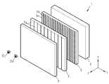
도 2는 본 발명의 일 실시예에 따른 2D/3D 겸용 영상표시장치의 광학적 구성을 보인 개략적인 도면이다.2 is a schematic view showing an optical configuration of a 2D / 3D dual display device according to an exemplary embodiment of the present invention.
도 3은 도 2의 2D/3D 겸용 영상표시장치의 상측에서 본 개략적인 단면도이다.FIG. 3 is a schematic cross-sectional view of the 2D / 3D dual display device of FIG. 2 as viewed from above.
도 4는 도 2의 2D/3D 겸용 영상표시장치에 채용되는 화상패널에 영상 데이터를 입력하는 구성을 개략적으로 도시한 도면이다.4 is a diagram schematically showing a configuration for inputting image data to an image panel employed in the 2D / 3D dual display device of FIG.
도 5는 도 2의 2D/3D 겸용 영상표시장치에 채용되는 화상패널의 개략적인 단면도이다.5 is a schematic cross-sectional view of an image panel employed in the 2D / 3D combined image display apparatus of FIG.
도 6은 도 5의 화상패널의 컬러필터 구조를 보인 도면이다.Fig. 6 is a diagram showing a color filter structure of the image panel of Fig. 5;
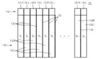
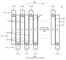
도 7 내지 도 11은 도 2의 2D/3D 겸용 영상표시장치에 채용되는 백라이트 유닛의 다양한 예들을 보여준다.FIGS. 7 to 11 show various examples of the backlight unit employed in the 2D / 3D dual display device of FIG.
도 12는 화상패널에서 좌시역용 영상과 우시역용 영상이 순차 스캔되는 과정을 도시한다.FIG. 12 illustrates a process of sequentially scanning a left-view zone image and a right-view zone image in the image panel.
도 13a와 도 13b는, 화상패널에서 좌시역용 영상과 우시역용 영상이 순차 스캔될 때, 좌시역용 세그먼트 광원과 우시역용 세그먼트 광원이 각각 순차구동되는 동작을 도시한다.FIGS. 13A and 13B illustrate sequential driving of a left-seg- mented segment light source and a right-eye segmented segment light source, respectively, when the left-channel and right-channel images are sequentially scanned in the image panel.
도 14는 화상패널에 2D 영상이 스캔될 때, 좌시역용 세그먼트 광원과 우시역용 세그먼트 광원이 함께 순차구동되는 동작을 도시한다.Fig. 14 shows an operation in which a left segment segment light source and a right segment segment light source are sequentially driven together when a 2D image is scanned on the image panel.
도 15는 본 발명의 다른 실시예에 따른 2D/3D 겸용 영상표시장치에 채용되는 화상패널을 도시한다.FIG. 15 illustrates an image panel employed in a 2D / 3D combined image display apparatus according to another embodiment of the present invention.
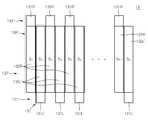
도 16은 도 15의 2D/3D 겸용 영상표시장치에 채용되는 백라이트 유닛을 도시한다.FIG. 16 shows a backlight unit employed in the 2D / 3D dual display device of FIG.
도 17a와 도 17b는 3D 영상 프레임 각각이 좌영상 및 우영상 단색 필드로 분해되었을 때, 좌영상 및 우영상 단색 필드들의 스캔되는 순서를 도시한다.FIGS. 17A and 17B show the scan order of the left and right image monochrome fields when the 3D image frames are decomposed into the left image and the right image monochrome fields, respectively.
도 18은 화상패널에서 좌영상 및 우영상 단색 필드들이 순차 스캔되는 과정을 도시한다.FIG. 18 shows a process of sequentially scanning left and right monochrome fields in the image panel.
도 19a와 도 19b는 화상패널에서 좌시역용 단색 필드들과 우시역용 단색 필드들이 순차 스캔될 때, 좌시역용 세그먼트 광원과 우시역용 세그먼트 광원이 각각 순차구동되는 동작을 도시한다.FIGS. 19A and 19B illustrate sequential driving of the left-seg- ment segment light source and the right-eye segment light source, respectively, when the left-field monochrome fields and the right-field monochrome fields are sequentially scanned in the image panel.
도 20은 화상패널에 2D 단색 필드가 스캔될 때, 좌시역용 세그먼트 광원과 우시역용 세그먼트 광원이 함께 순차구동되는 동작을 도시한다.Fig. 20 shows an operation in which a left stationary segment light source and a right stationary segment light source are sequentially driven together when a 2D solid color field is scanned on an image panel.
<도면의 주요 부분에 대한 부호의 설명>Description of the Related Art
1...3D 겸용 액정표시장치3...백라이트 유닛1 ... 3D combined liquid
5...광스위치7...렌티큘러 렌즈 시트5 ...
9...액정패널10...2D/3D 겸용 액정표시장치9 ...
13,13′...백라이트 유닛17...렌티큘러 렌즈 시트13, 13 '
19,19′...화상패널21...게이트 드라이버19, 19 '...
23...데이터 드라이버25...타이밍 컨트롤러23
27...인버터131,131′,134...광원부27 ...
132,132′...도광 세그먼트133...광차단막132, 132 '... light-guiding
135...광학시트191,196...편광판135 ...
192,195...유리기판193...액정층192,195
194...컬러필터D1,D2,…,Dn...데이터라인194 ... color filters D1 , D2 , ... , Dn ... data line
G1,G2,…,Gm...게이트라인OL...좌시역G1 , G2 , ... , Gm ... gate line OL ... stationary station
OR...우시역P...화소OR ... Wuxi station P ... pixel
S1,S2,…,SN...광출사면S1 , S2 , ... , SN ... light exit surface
본 발명은 백라이트 유닛 및 이를 채용한 2D/3D 겸용 액정표시장치에 관한 것으로, 더욱 상세하게는, 렌티큘러 렌즈 시트에 좌시역용 광과 우시역용 광을 공급하는 구조를 간단히 한 백라이트 유닛 및 이를 채용한 2D/3D 겸용 액정표시장치 에 관한 것이다.BACKGROUND OF THE
기술이 발전함에 따라 더욱 실감있는 영상을 표시하는 영상표시장치가 요청되고 있다. 이에 따라, 영상을 표시하는 화소를 증가시킨 고해상도 영상표시장치에 개발에서 나아가, 입체로 영상을 보여줄 수 있는 3D 영상표시장치가 개발되고 있다. 이러한 3D 영상표시장치는 TV에 적용될 수 있을 뿐만 아니라, 의료영상, 게임, 광고, 교육, 군사등 여러 분야에 적용됨으로써, 입체 효과에 의한 더욱 큰 효과가 기대될 수 있다.As technology develops, a video display device that displays a more realistic image is being demanded. Accordingly, there has been developed a 3D image display device capable of displaying a stereoscopic image in addition to the development of a high-resolution image display device in which pixels for displaying an image are increased. Such a 3D image display device can be applied not only to a TV but also to various fields such as a medical image, a game, an advertisement, an education, a military, and the like.
입체 영상은 사람의 두 눈을 통한 스테레오 시각의 원리에 의해 이루어지는데, 두 눈이 약 65mm 정도 떨어져서 존재하기 때문에 나타나는 양안시차(binocular parallax)가 입체감의 가장 중요한 요인이라고 할 수 있다. 이에 착안해 눈에 보이는 실제 영상과 동일한 영상을 두 눈에 입력할 수만 있다면 입체감은 쉽게 표현된다. 예컨대, 특성이 동일한 2대의 카메라를 양안 간격만큼 벌려 놓고 촬영한 후 왼쪽 카메라로 찍은 좌영상은 왼쪽 눈에만 보이게 하고, 오른쪽 카메라로 찍은 우영상은 오른쪽 눈에만 비춰줌으로써 입체감을 표현할 수 있다.Stereoscopic images are made by the principle of stereoscopic vision through the two eyes of a person. Binocular parallax, which occurs because the eyes are separated by about 65mm, is the most important factor of the stereoscopic effect. The stereoscopic effect can be easily expressed if the same image as the actual visual image can be input into the two eyes by focusing on this. For example, two cameras having the same characteristics are spaced apart from each other by a distance of two, and a left image captured by the left camera is displayed on the left eye, and a right image captured by the right camera is displayed on the right eye.
이와 같이 양안시차(binocular parallax)를 이용하는 3D 영상표시장치에는무안경 방식(autostereoscopic)과 안경 방식(stereoscopic)이 있다. 안경을 사용하지 않고 좌우 영상을 분리하여 입체 영상을 얻는 무안경 방식의 영상표시장치에는 패럴렉스 배리어(parallax barrier) 방식, 렌티큘러(lenticular) 방식, 집적 영상(integral imaging) 방식, 홀로그래피(holography) 방식 등이 있고, 안경을 이용한 영상표시장치에는 편광 안경식 방식과 셔터 안경식 방식 등이 있다.As described above, a 3D image display device using a binocular parallax has an autostereoscopic mode and a stereoscopic mode. A non-eyeglass image display apparatus for obtaining a stereoscopic image by separating left and right images without using glasses is provided with a parallax barrier system, a lenticular system, an integral imaging system, a holography system And the like, and a video display device using glasses includes a polarized spectacle mode and a shutter spectacle mode.
이러한 3D 영상표시장치 중에서, 액정패널과 같은 화상을 표시하는 화상패널 기술이 발전함에 따라, 최근 들어 무안경 방식에 대한 개발이 활발하다. 도 1은 이러한 무안경 방식의 3D 영상표시장치를 예시적으로 보여준다. 도 1을 참조하면, 제안되고 있는 3D 영상표시장치(1)는 백라이트 유닛(3)과, 광스위치(5)와 렌티큘러 렌즈 시트(lenticular lens sheet)(7)와, 액정패널(9)을 구비한다. 상기 렌티큘러 렌즈 시트(7)는 시청자의 두 눈을 잇는 선분에 수직한 방향, 즉 도 1에 도시된 y 방향으로 길게 연장된 반원통형 렌즈(semicylindrical lens)(7a)들이 나란히 배열된 광학부재이다. 한편, 상기 광스위치(5)는 각 반원통형 렌즈(7a)들에 대응되어 스트라이프 형태로 형성되는 좌시역용 셀(5a)과 우시역용 셀(5b)을 포함한다. 이 좌시역용 셀(5a)과 우시역용 셀(5b)은 투명한 상태와 불투명한 상태 사이에서 교대로 스위칭되는 것으로, 화상패널(2)에 공급되는 좌시역용 영상신호 및 우시역용 영상신호에 동기되어 렌티큘러 렌즈 시트(7) 쪽으로 좌시역용 광과 우시역용 광이 번갈아가며 통과될 수 있도록 한다. 이때, 렌티큘러 렌즈 시트(7)는, 입사되는 좌시역용 광을 관찰자의 좌시역(OL)으로 향하게 하며, 입사되는 우시역용 광을 관찰자의 우시역(OR)으로 향하게 한다. 액정패널(9)는 좌시역용 영상과 우시역용 영상을 교대로 표시한다. 이러한 3D 영상표시장치(1)는 액정패널(9)에 표시되는 좌시역용 영상과 우시역용 영상에 동기시켜 좌시역용 광과 우시역용 광을 번갈아 공급함으로써, 관찰자가 3D 영상을 볼 수 있도록 한다.Among such 3D image display devices, as image panel technology for displaying an image such as a liquid crystal panel develops, development of a non-eyeglass system has been actively conducted recently. FIG. 1 exemplarily shows such a non-eyeglass type 3D image display apparatus. Referring to FIG. 1, a 3D
그런데, 이러한 3D 영상표시장치(1)는 백라이트 유닛(3)과 렌티큘러 렌즈 시 트(7) 사이에 개재되는 광스위치(5)를 필요로 하므로, 조립공정을 복잡하게 하며, 제조비용을 증가시키게 된다. 또한, 광스위치(5)로는 통상적으로 편광스위치를 이용하는데, 이러한 편광스위치는 광이용효율을 악화시킨다.However, such a 3D
한편 이러한 3D 영상표시장치(1)는 좌시역용 영상 및 우시역용 영상을 표시하는데 액정패널(9)의 전 화소를 사용하므로, 액정패널(9)의 해상도를 좌시역용 영상 및 우시역용 영상의 해상도가 되도록 할 수 있다. 그러나, 이러한 3D 영상표시장치(1)는 3D 영상의 1 프레임을 위해 좌시역용 영상의 1 프레임과 우시역용 영상의 1 프레임이 필요하므로, 프레임율(frame rate)에서 손해를 보게 된다. 프레임율이 낮아지게 되면, 액정패널(9)에서의 응답속도의 한계로 말미암아, 좌시역용 영상이나 우시역용 영상이 즉시 바뀔 수가 없고, 이에 따라 좌시역용 영상과 우시역용 영상이 섞이는 크로스토크(crosstalk)의 문제가 심각해질 수 있다.Since the 3D
본 발명은, 상술한 종래의 3D 영상표시장치의 문제점을 개선하기 위해 안출된 것으로, 그 구조를 개선하여 광학부품수를 줄여 제조공정을 단순하게 하고 제조비용을 저감시키며, 광이용효율을 높인 백라이트 유닛 및 이를 채용한 2D/3D 겸용 액정표시장치를 제공하는 것을 목적으로 한다.The present invention has been conceived to solve the problems of the conventional 3D image display apparatus described above, and it is an object of the present invention to improve the structure thereof to reduce the number of optical components, simplify the manufacturing process, reduce the manufacturing cost, Unit and a 2D / 3D combined liquid crystal display employing the same.
상기의 목적을 달성하기 위하여, 본 발명에 따른 백라이트 유닛은, 상패널과, 상기 화상패널의 배면에 배치되어 조명되는 광을 좌우시역으로 분리시키는 렌티큘러 렌즈 시트를 포함하는 2D/3D 겸용 영상표시장치에 채용되어, 상기 렌티큘러 렌즈 시트에 광을 공급하는 것으로서, 좌시역용 광이 출사되는 복수의 좌시역용 세그먼트 광원과; 우시역용 광이 출사되는 복수의 우시역용 세그먼트 광원;을 구비하며, 상기 복수의 좌시역용 세그먼트 광원과 상기 복수의 우시역용 세그먼트 광원은, 서로 교대로 배열되어 면광원을 이루는 것을 특징으로 한다.In order to achieve the above object, a backlight unit according to the present invention includes a top panel and a 2D / 3D dual-purpose video display device including a top panel and a lenticular lens sheet arranged on the back surface of the image panel, A plurality of left-eye stationary segment light sources for supplying light to the lenticular lens sheet, the left-eye stationary segment light source emitting light for left-eye station; And a plurality of right-eye segment light sources and a plurality of right-eye segment light sources are alternately arranged to form a surface light source.
여기서, 상기 복수의 좌시역용 세그먼트 광원 각각은 스트라이프 형상의 광출사면을 갖는 좌시역용 도광 세그먼트와 상기 좌시역용 도광 세그먼트에 광을 공급하는 좌시역용 점광원을 포함하고, 상기 복수의 우시역용 세그먼트 광원 각각은 스트라이프 형상의 광출사면을 갖는 우시역용 도광 세그먼트와 상기 우시역용 도광 세그먼트에 광을 공급하는 우시역용 점광원을 포함하며, 상기 좌시역용 도광 세그먼트와 상기 우시역용 도광 세그먼트는 서로 교대로 배열되어 도광판을 이루는 것일 수 있다.Each of the plurality of left-field segment light sources includes a left-field light-guiding segment having a stripe-shaped light exit surface and a left-point stationary point light source for supplying light to the left-field backlit segment, wherein each of the plurality of right- The light guide segment for the left seat and the light guide segment for the right seat are arranged alternately with each other so that the light guide segment for the right light guide segment is disposed alternately with the light guide segment for the right light guide segment, Lt; / RTI >
또는, 상기 복수의 좌시역용 세그먼트 광원 각각은 좌시역용 광학시트와 상기 좌시역용 광학시트의 배면에 배치되는 좌시역용 광원을 포함하며, 상기 복수의 우시역용 세그먼트 광원 각각은 우시역용 광학시트와 상기 우시역용 광학시트의 배면에 배치되는 우시역용 광원을 포함할 수 있다.Alternatively, each of the plurality of left-eye segment light sources may include a left-eye optical sheet and a left-eye station light source disposed on the back surface of the left-eye optical sheet, wherein each of the plurality of right-eye segment light sources includes a right- And a right-side light source disposed on the back surface of the optical sheet.
또한, 상기의 목적을 달성하기 위하여, 본 발명에 따른 2D/3D 겸용 영상표시장치는, 화상패널과; 상기의 백라이트 유닛과; 시청자의 두 눈을 잇는 선분에 수직한 방향으로 배열되는 복수의 반원통형 렌즈를 갖는 것으로, 상기 화상패널과 상기 백라이트 유닛 사이에 배치되어, 상기 좌시역용 광은 좌시역 방향으로 향하게 하며 상기 우시역용 광은 우시역 방향으로 향하게 하는 렌티큘러 렌즈 시트;를 포함하는 것을 특징으로 한다.According to another aspect of the present invention, there is provided a 2D / 3D combined image display apparatus including: an image panel; A backlight unit; And a plurality of semicylindrical lenses arranged in a direction perpendicular to a line segment connecting two eyes of a viewer, wherein the left-side stationary light is directed to a leftward-stationary direction, and the right- And a lenticular lens sheet facing the direction of the right wing.
여기서, 상기 화상패널은 표시되는 영상의 수직라인을 시청자의 두 눈을 잇는 선분과 평행한 방향으로 스캔할 수 있다.Here, the image panel can scan a vertical line of a displayed image in a direction parallel to a line segment connecting two eyes of a viewer.
이하, 첨부된 도면들을 참조하면서 본 발명의 바람직한 실시예를 상세히 설명하기로 한다. 그러나 아래에 예시되는 실시예는 본 발명의 범위를 한정하는 것이 아니며, 본 발명을 이 기술 분야에서 통상의 지식을 가진 자에게 충분히 설명하기 위해 제공되는 것이다. 이하의 도면들에서 동일한 참조부호는 동일한 구성요소를 지칭하며, 도면상에서 각 구성요소의 크기는 설명의 명료성과 편의상 과장되어 있을 수 있다.Hereinafter, preferred embodiments of the present invention will be described in detail with reference to the accompanying drawings. However, the embodiments illustrated below are not intended to limit the scope of the invention, but rather to provide a thorough understanding of the invention to those skilled in the art. In the following drawings, like reference numerals refer to like elements, and the size of each element in the drawings may be exaggerated for clarity and convenience of explanation.
도 2는 본 발명의 일 실시예에 따른 2D/3D 겸용 영상표시장치의 광학적 구성을 보인 개략적인 도면이며, 도 3은 도 2의 2D/3D 겸용 영상표시장치의 상측에서 본 개략적인 단면도이다.FIG. 2 is a schematic view showing an optical configuration of a 2D / 3D dual display device according to an exemplary embodiment of the present invention, and FIG. 3 is a schematic cross-sectional view of the 2D / 3D dual display device of FIG. 2 as viewed from above.
도 2와 도 3을 참조하면, 본 실시예의 2D/3D 겸용 영상표시장치(10)는 광을 공급하는 백라이트 유닛(13)과, 상기 백라이트 유닛(13)에서의 광을 관찰자의 좌우 시역(OL,OR)으로 분기시키는 렌티큘러 렌즈 시트(17), 2D 영상 또는 3D 영상을 표시하는 화상패널(19)을 포함한다.2 and 3, the 2D / 3D combined
상기 화상패널(19)은 3D 모드의 경우, 좌시역용 영상과 우시역용 영상을 교대로 표시하며, 2D 모드의 경우, 통상의 2D 영상을 표시한다. 화상패널(19)로는 액정패널이 채용될 수 있다. 본 실시예의 화상패널(19)은, 표시되는 영상의 수직라인 을 시청자의 두 눈을 잇는 선분과 평행한 방향인 x 방향으로 스캔된다. 이는, 후술하는 바와 같이, 화상패널(19)에 표시되는 영상의 스캔에 동기되어 백라이트(13)가 순차구동되기 위함이다.In the case of the 3D mode, the
도 4를 참조하면, 상기 화상패널(19)은 m×n 개의 화소들이 매트릭스 타입으로 배열되고 있다. m개의 게이트라인들(G1,G2,…,Gm)과 n개의 데이터라인들(D1,D2,…,Dn)은 서로 교차되며, 게이트라인들(G1,G2,…,Gm)과 데이터라인들(D1,D2,…,Dn)의 교차점에 TFT가 형성되어 화소를 구성된다.Referring to FIG. 4, in the
상기 화상패널(19)에 스캔신호를 공급하기 위한 게이트 드라이버(21)와 데이터 신호를 공급하기 위한 데이터 드라이버(23)가 구비된다. 상기 게이트 드라이버(21)와 상기 데이터 드라이버(23)는 타이밍 콘트롤러(25)에 의해 제어된다. 타이밍 콘트롤러(25)는 수평 동기신호를 이용하여 상기 데이터 드라이버(23)을 제어하고, 수직 동기신호를 이용하여 상기 게이트 드라이버(21)를 제어한다. 화소 각각에 형성된 TFT는 게이트 드라이버(21)로부터 공급되는 스캔신호에 응답하여, 데이터 드라이버(23)로부터 공급되는 데이터신호에 따라 스위칭 동작한다. 게이트 드라이버(21)는 타이밍 콘트롤러(25)의 수직 동기신호에 응답하여 스캔펄스를 게이트라인들(G1,G2,…,Gm)에 순차적으로 공급하여 데이터 신호가 공급되는 화상패널(19)의 수직라인을 선택한다. 데이터 드라이버(23)는 타이밍 콘트롤러(25)의 수평 동기신호에 응답하여 영상 신호를 데이터라인들(D1,D2,…,Dn)에 공급하여, 표시되는 영상을 수직라인단위로 화상패널(19)에 기입하도록 한다. 이와 같이 기입된 수직라인은 게 이트 드라이버(21)의 스캔신호에 따라 수평방향으로 스캔되며, 2차원의 영상이 표시된다. 그리고, 상기 백라이트 유닛(13)은 인버터(27)에 의해 구동되며, 상기 인버터(27)는 타이밍 콘트롤러(27)에 의해 제어된다.A
본 실시예의 화상패널(19)은, 도 5에 도시되는 바와 같은 컬러필터를 갖는 액정패널이다. 도 5를 참조하면, 화상패널(19)은 제1기판(192), 제2기판(195) 및 제1기판(192)과 제2기판(195) 사이에 봉지된 액정층(193)을 포함한다. 제1기판(192) 및 제2기판(195)의 외면에는 각각 제1 및 제2편광판(191,196)이 부착되어 있다. 제2기판(194)의 내면에는 컬러필터(194)가 마련되어 있다.The
컬러필터(194)는 도 6에 예시적으로 도시되듯이, 수평방향, 즉 x방향으로 길게 연장된 스트라이프 형상의 적색필터, 녹색필터, 및 청색필터가 열을 지어 반복적으로 배열될 수 있다. 도시된 화상패널(19)은 m×n 개의 화소들(P)을 가지고 있으며, 각 화소(P)는 적색화소, 녹색화소, 및 청색화소로 이루어져 있다. 각 화소(P)에 영상 데이터를 공급하는 데이터라인(D1,D2,…,Dn) 각각은 적색 데이터라인(D1R,D2R,…,DnR), 녹색 데이터라인(D1G,D2G,…,DnG), 및 청색 데이터라인(D1B,D2B,…, DnB)을 포함한다. 상기 적색 데이터라인들(D1R,D2R,…,DnR), 녹색 데이터라인들(D1G,D2G,…,DnG), 및 청색 데이터라인들(D1B,D2B,…, DnB) 각각과 게이트라인들(G1,G2,…,Gm)의 교차점은 적색화소, 녹색화소, 및 청색화소를 이룬다. 적색필터의 스트라이프 형상의 열은 적색 데이터라인들(D1R,D2R,…,DnR)에 대응되며, 녹색필터 의 스트라이프 형상의 열은 녹색 데이터라인들(D1G,D2G,…,DnG)에 대응되며, 청색필터의 스트라이프 형상의 열은 청색 데이터라인들(D1B,D2B,…, DnB)에 대응될 수 있다.The
다시 도 2와 도 3을 참조하면, 렌티큘러 렌즈 시트(17)는 시청자의 두 눈을 잇는 선분에 수직한 방향, 즉 y 방향으로 길게 연장된 반원통형 렌즈(17a)가 나란히 배열된 것으로서, 상기 화상패널(19)과 상기 백라이트 유닛(13) 사이에 배치되어, 좌시역용 광(LL)은 좌시역(OL)을 향하게 하며 우시역용 광(LR)은 우시역(OR)을 향하게 한다. 이와 같이 시역을 분리하는 렌티큘러 렌즈 시트(17)를 화상패널(19)의 배면에 배치함으로써, 화상패널의 전면에 렌티큘러 렌즈 시트를 배치하는 3D 영상표시장치에 비하여, 좌시역용 영상 및 우시역용 영상 각각을 표시하는데 화상패널(19)의 전체 화소를 사용하므로 고해상도의 이미지 구현이 가능하다. 한편, 상기 반원통형 렌즈(17a)의 배열간격이나 굴절력 등의 광학적 설계는 당해 분야의 숙련된 당업자가 사용자의 시청거리나, 백라이트 유닛(13)과 화상패널(19)과의 거리 등을 고려하여 적절히 설계할 수 있는 사항이므로, 이에 대한 상세한 설명은 생략하기로 한다.Referring again to FIGS. 2 and 3, the
백라이트 유닛(13)은 복수의 좌시역용 세그먼트 광원(13L)과 복수의 우시역용 세그먼트 광원(13R)이 서로 교대로 배열되어 면광원을 이룬다. 이때, 좌시역용 세그먼트 광원(13L)과 우시역용 세그먼트 광원(13R)은, 쌍을 이루어 상기 렌티큘러 렌즈 시트(17)의 반원통형 렌즈(17a)마다 적어도 하나씩 대응되도록 배치된다. 가령, 도 3에 도시되듯이, 서로 인접한 좌시역용 세그먼트 광원(13L)과 우시역용 세 그먼트 광원(13L)은, 쌍을 이루어 상기 복수의 반원통형 렌즈(17a)에 일대일로 마주보도록 배치될 수 있다. 상기 복수의 좌시역용 세그먼트 광원(13L)는 상기 렌티큘러 렌즈 시트(17)에 좌시역용 광(LL)을 공급하며, 상기 복수의 우시역용 세그먼트 광원(13R)는 상기 렌티큘러 렌즈 시트(17)에 우시역용 광(LR)을 공급한다.The
도 7 내지 도 11은 본 실시예의 2D/3D 겸용 영상표시장치에 채용될 수 있는 백라이트 유닛의 다양한 예들을 보여준다.FIGS. 7 to 11 show various examples of a backlight unit that can be employed in the 2D / 3D combined image display apparatus of this embodiment.
도 7과 도 8은 일 예에 따른 백라이트 유닛의 개략적인 분해 사시도 및 상면도이다.7 and 8 are a schematic exploded perspective view and a top view of a backlight unit according to an example.
도 7과 도 8을 참조하면, 본 예의 백라이트 유닛(13)은 광을 공급하는 복수의 점광원(131)과, 상기 복수의 점광원(131)에서 방출된 광을 가이드하는 도광판을 이루는 복수의 도광 세그먼트(132)를 포함한다. 본 예의 백라이트 유닛(13)은 점광원들(131)들이 도광 세그먼트들(132)의 측부에 배치되는 측면발광형(edge emitting type) 구조를 갖는다.7 and 8, the
상기 점광원들(131) 각각은 예를 들어 LED와 같은 발광소자가 될 수 있다. 본 예의 백라이트 유닛(13)은, 컬러필터(도 5의 194)를 갖는 화상패널(도 2의 19)에 채용하는 2D/3D 겸용 영상표시장치(도 2의 10)에 사용되므로, 백색광을 공급하는 것이 바람직하다. 따라서, 본 예의 광원(131)은 백색광을 방출하는 백색광원이 될 수 있다.Each of the point
상기 복수의 도광 세그먼트(132) 각각은 스트라이프 형상의 광출사면(S1,S2, …,SN)을 갖는 바(bar) 타입의 도광부재이다. 도광 세그먼트들(132)의 몸체는 입사광을 투과시킬 수 있는 투명재질로 구성되며, 예컨대 광 투과율과 내후성이 좋은 플라스틱 재료인 PMMA(Polymethylmethacrylate)이 사용될 수 있다. 이러한 복수의 도광 세그먼트(132)는, 상기 광출사면들(S1,S2,…,SN)이 동일면상에 나란히 배열되도록 배치되어 도광판을 이룬다.Each of the plurality of
상기 복수의 점광원(131)은 좌시역용 점광원들(131L)과 우시역용 점광원들(131R)로 나뉘어지며, 상기 복수의 도광 세그먼트(132)은 상기 좌시역용 점광원들(131L)로부터 광을 공급받는 좌시역용 도광 세그먼트들(132L)과 상기 우시역용 점광원들(131R)로부터 광을 공급받는 우시역용 도광 세그먼트들(132R)로 나뉘어진다. 좌시역용 점광원(131L)과 좌시역용 도광 세그먼트(132L)는 좌시역용 세그먼트 광원(13L)을 이루며, 우시역용 점광원(131R′)과 우시역용 점광원(131R′)은 우시역용 세그먼트 광원(13R)을 이룬다. 이때, 좌시역용 도광 세그먼트(132L)와 우시역용 도광 세그먼트(132R)는 서로 교대로 배열되어 있다.The plurality of point
좌시역용 도광 세그먼트(132L)에서 가이드되는 좌시역용 광(LL)과 우시역용 도광 세그먼트(132R)에서 가이드되는 우시역용 광(LR)이 서로 섞이지 않도록, 좌시역용 도광 세그먼트(132L)와 우시역용 도광 세그먼트(132R) 사이에는 광차단막(133)이 개재될 수 있다. 이러한 광차단막(133)은 광을 투과하지 않는 물질로 형성된 것으로, 광을 반사하는 반사막이 될 수도 있고, 광을 흡수하는 광흡수막이 될 수도 있다.The left side
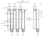
좌시역용 점광원(131L)과 우시역용 점광원(131R)은 좌시역용 도광 세그먼트(132L)의 일 단부와 우시역용 도광 세그먼트(132R)의 일 단부에 각각 배치된다. 이때, 점광원들(131)이 배치되는 좌시역용 도광 세그먼트(132L)의 일 단부와 우시역용 도광 세그먼트(132R)의 일 단부는 서로 반대 방향이다. 이는 좌시역용 광(LL)과 우시역용 광(LR)이 도광판을 이루는 도광 세그먼트들(132)의 반대쪽에서 공급됨으로써, 백라이트 유닛(13)이 더욱 균일한 면광원이 되기 위함이다. 그러나, 본 발명의 백라이트 유닛(13)은 이러한 점광원 배치 구성에 한정되지 않는다. 가령, 도 9에 도시되듯이 점광원들(131)이 배치되는 좌시역용 도광 세그먼트(132L)의 일 단부와 우시역용 도광 세그먼트(132R)의 일 단부가 서로 같은 방향일 수 있다. 나아가, 도 10에 도시되듯이 좌시역용 점광원(131L)와 우시역용 점광원(131R)은 좌시역용 도광 세그먼트(132L)의 양 단부와 우시역용 도광 세그먼트(132R)의 양 단부에 각각 배치될 수도 있다.The left stationary point
도 11은 다른 예에 따른 백라이트 유닛의 개략적인 분해 사시도이다11 is a schematic exploded perspective view of a backlight unit according to another example
도 11을 참조하면, 백라이트 유닛(13)은 광을 공급하는 복수의 광원(134)과, 상기 복수의 광원(134)에서 방출된 광을 균일하게 하는 복수의 광학시트(135)를 포함한다. 본 예의 백라이트 유닛(13)은 광원들(134)들이 광학시트들(132)의 배면에 배치되는 직하형(direct type) 구조를 갖는다. 본 예의 백라이트 유닛(13)은 직하형인 점을 제외하고는 도 7 및 도 8을 참조하여 설명한 백라이트 유닛(13)과 실질적으로 동일하므로, 반복되는 설명은 생략하기로 한다.11, the
상기 광원(134)은 스트라이프 형상의 면광을 출사하는 것으로써, 예를 들어, 도면에 도시되는 바와 같은 점광원(134a)이 일렬로 배열된 구성을 가질 수 있다. 그러나, 상기 광원(134)은 이에 한정되는 것은 아니며, 냉음극 형광램프(CCFL)와 같은 선광원이 스트라이프 길이 방향으로 설치된 구성을 가지거나, 그 밖의 스트라이프 형상의 면광을 출사하는 다양한 광원이 채용될 수 있다. 상기 광학시트(135)는 광원(134)에서 출사되는 광의 특성을 향상시키고자 하는 것으로, 가령 광을 균일하게 하는 확산시트 등을 포함할 수 있다. 상기 복수의 광원들(134)은 좌시역용 광원들(134L)과 우시역용 광원들(134R)로 나뉘어지며, 상기 복수의 광학시트(135)는 상기 좌시역용 광원들(134L)에 대응되는 좌시역용 광학시트들(135L)과 상기 우시역용 광원들(134R)에 대응되는 우시역용 광학시트들(135R)로 나뉘어진다. 좌시역용 광원(134L)과 우시역용 광원(134R)은 서로 교대로 배열되어 있다. 좌시역용 광학시트(135L)를 통과하는 좌시역용 광과 우시역용 광학시트(135L)를 통과하는 우시역용 광이 서로 섞이지 않도록, 좌시역용 광학시트(135L)와 우시역용 광학시트(135L) 사이에는 광차단막(133)이 개재될 수 있다.The
다음으로, 본 실시예의 2D/3D 겸용 영상표시장치의 동작을 설명하기로 한다.Next, the operation of the 2D / 3D dual display device of the present embodiment will be described.
먼저 3D 영상을 표시하는 과정을 설명한다.First, a process of displaying a 3D image will be described.
도 2와 도 3을 참조하면, 화상패널(19)은 좌영상과 우영상을 번갈아가며 표시한다. 전술한 바와 같이 화상패널(19)은 영상을 수직라인별로 표시하고, 이를 수평방향으로 스캔하여 2차원의 좌영상과 우영상을 표시한다. 도 12를 참조하면, 가령, t=0에서 화상패널(도 2의 19)이 우영상(R)을 표시하고 있다고 하면, T/8 시간 이 경과한 후에는 화상패널의 1/4 영역에는 좌영상(L)이 새롭게 표시되고 있으며, 화상패널(19)의 나머지 3/4 영역에는 우영상(R)이 남아있다. 다시 T/8 시간이 경과하면, 화상패널의 1/2 영역에는 좌영상(L)이 표시되고 있으며, 화상패널(19)의 나머지 1/2 영역에는 우영상(R)이 남아있게 된다. 스캔이 계속됨에 따라, t=T/2에 화상패널(19)은 좌영상(L)만 표시되게 되며, 다시 T/2이 지나면 우영상(R)만이 표시되게 된다. 이때, 주기 T는 3D 영상의 1 프레임, 즉 좌영상(L) 1 프레임과 우영상(R)의 1 프레임이 스캔되는 총 시간을 의미한다.2 and 3, the
한편, 백라이트 유닛(13)은 상기 화상패널(19)에 표시되는 좌영상(L)과 우영상(R)에 동기되어, 좌시역용 광(LL)과 우시역용 광(LR)을 번갈아가며 조명한다. 가령, 도 3에 도시되듯이, 반원통형 렌즈(17a)에 일대일로 마주보도록 배치된 세그먼트 광원 쌍 중에서 좌측에 위치한 좌시역용 세그먼트 광원(13L)에서 출사된 좌시역용 광(LL)은 렌티큘러 렌즈 시트(17)을 지나 관찰자의 좌시역(OL)을 향하게 되며, 우측에 위치한 우시역용 세그먼트 광원(13R)에서 출사된 우시역용 광(LR)은 렌티큘러 렌즈 시트(17)을 지나 관찰자의 우시역(OR)을 향하게 된다. 도 3에는 편의상 좌시역(OL)과 우시역(OR)이 하나씩만 도시되어 있으나, 각 세그먼트 광원(13)에서 출사된 광은 렌티큘러 렌즈 시트(17)의 다른 반원통형 렌즈들(17a)을 지나 도시되지 않은 복수의 좌시역 및 우시역을 형성한다.On the other hand, the
전술한 바와 같이 좌영상과 우영상은 수평방향으로 스캔되며 화상패널(19)에 기입되므로, 백라이트 유닛(13)은 스캔신호에 동기되어 세그먼트 광원(13)별로 순차적으로 구동된다. 도 13a와 도 13b는 백라이트 유닛(13)의 순차구동을 보여준다.As described above, since the left and right images are scanned in the horizontal direction and written in the
도 13a를 참조하면, 화상패널(19)에 좌영상(도 12의 L)이 수직라인별로 기입되어 수평방향으로 스캔될 때, 기입이 완료된 수직라인에 대응되는 좌시역용 점광원(131L)이 점등하며, 좌시역용 점광원(131L)에서 방출된 광은 좌시역용 도광 세그먼트(132L)를 통해 화상패널(19)의 기입이 완료된 수직라인 영역을 조명한다.13A, when the left image (L in FIG. 12) is written in the
한편, 도 13b를 참조하면, 화상패널(19)에 우영상이 수직라인별로 기입되어 수평방향으로 스캔될 때, 기입이 완료된 수직라인에 대응되는 우시역용 점광원(131R)이 점등하며, 우시역용 점광원(131R)에서 방출된 광은 우시역용 도광 세그먼트(132R)를 통해 화상패널(19)의 기입이 완료된 수직라인 영역을 조명한다.13B, when the right image is written in the
이와 같이 화상패널(19)에 표시되는 영상의 스캔신호에 동기되어 백라이트 유닛(13)을 순차 구동함으로써, 광의 공급시간을 늘릴 수 있으므로, 프레임률을 높이거나 휘도를 증대시킬 수 있다.Since the
다음으로 2D 영상을 표시하는 과정을 설명한다.Next, a process of displaying a 2D image will be described.
화상패널(19)에는 통상의 2D 영상이 수직라인별로 기입되어 수평방향으로 스캔된다. 한편, 백라이트 유닛(13)은 상기 화상패널(19)에 기입되는 2D 영상의 스캔신호에 동기되어, 좌시역용 및 우시역용 세그먼트 광원(13L,13R)이 순차구동된다. 가령, 도 14에 도시되듯이, 화상패널(19)에 2D 영상이 수직라인별로 기입되어 수평방향으로 스캔될 때, 기입이 완료된 수직라인에 대응되는 좌시역용 점광원(131L) 또는 우시역용 점광원(131R)이 점등하며, 대응되는 좌시역용 도광 세그먼트(132L) 또는 우시역용 도광 세그먼트(132R)를 통해 화상패널(19)의 기입이 완료된 수직라인 영역을 조명한다.In the
도 15는 본 발명의 다른 실시예에 따른 2D/3D 겸용 영상표시장치의 화상패널을 개략적으로 도시한 도면이며, 도 16은 본 실시예에 적용되는 백라이트 유닛의 개략적인 도면이다.FIG. 15 is a view schematically showing a picture panel of a 2D / 3D combined image display apparatus according to another embodiment of the present invention, and FIG. 16 is a schematic view of a backlight unit applied to the present embodiment.
본 실시예의 2D/3D 겸용 영상표시장치는 화상패널에 컬러필터가 없다는 점과, 백라이트 유닛의 광원구성이 달라진다는 점을 제외하고는 전술된 2D/3D 겸용 영상표시장치와 실질적으로 동일하다. 반복되는 설명을 피하기 위해, 차이점을 중심으로 설명하기로 한다.The 2D / 3D combined image display device of this embodiment is substantially the same as the aforementioned 2D / 3D combined image display device except that there is no color filter in the image panel and the light source configuration of the backlight unit is changed. To avoid repeated explanations, the difference will be mainly described.
본 실시예의 화상패널(19′)은 컬러필터가 없는 액정패널이 채용될 수 있다. 이러한 액정패널은 컬러필터가 없다는 점을 제외하고는 도 5에 도시된 액정패널과 실질적으로 동일하다. 컬러필터가 없으므로, 한 단위화소는 하나의 데이터라인들(D1,D2,…,Dn)과 게이트라인들(G1,G2,…,Gm)의 교차점으로 이루어진다.The image panel 19 'of this embodiment can employ a liquid crystal panel without a color filter. This liquid crystal panel is substantially the same as the liquid crystal panel shown in Fig. 5 except that there is no color filter. Since there is no color filter, one unit pixel consists of the intersection of one data line (D1 , D2 , ..., Dn ) and the gate lines (G1 , G2 , ..., Gm ).
한편, 백라이트 유닛(13′)은, 도 16에 도시되듯이, 광을 공급하는 복수의 점광원(131′)과, 상기 복수의 점광원(131′)에서 방출된 광을 가이드하는 도광판을 이루는 복수의 도광 세그먼트(132′)를 포함한다. 상기 복수의 점광원(131′)은 좌시역용 점광원들(131L′)과 우시역용 점광원들(131R′)로 나뉘어지며, 상기 복수의 도광 세그먼트(132′)은 상기 좌시역용 점광원들(131L′)로부터 광을 공급받는 좌시역용 도광 세그먼트들(132L′)과 상기 우시역용 점광원들(131R′)로부터 광을 공급받는 우시역용 도광 세그먼트들(132R′)로 나뉘어진다. 좌시역용 점광원(131L′)과 좌시역용 도광 세그먼트(132L′)는 좌시역용 세그먼트 광원(13L′)을 이루며, 우시역용 점광원(131R′)과 우시역용 도광 세그먼트(132R′)은 우시역용 세그먼트 광원(13R′)을 이룬다. 이때, 좌시역용 점광원(131L′)과 우시역용 점광원(131R′)은 각각 화상패널(19′)에 표시되는 단색 필드에 대응되는 단색광원들을 구비한다. 통상적으로 하나의 영상 프레임은 적색필드, 녹색필드, 및 청색필드로 분해되므로, 점광원(131′) 각각은 적색광원, 녹색광원, 및 청색광원을 구비한다. 컬러영상은 후술하는 바와 같이 하나의 영상프레임을 복수의 단색필드로 분해하고, 각 단색필드에 대응되는 단색광을 조명함으로써 구현된다. 나머지 백라이트 유닛(13′)의 구성요소는 도 7 및 도 8을 참조하여 설명된 백라이트 유닛과 실질적으로 동일하다.16, the backlight unit 13 'includes a plurality of point light sources 131' for supplying light and a light guide plate for guiding light emitted from the plurality of point light sources 131 ' And includes a plurality of light guiding segments 132 '. The plurality of point light sources 131 'are divided into left point point
본 실시예에 채용되는 백라이트 유닛(13′)은 도 16에 도시되는 구성에 한정되지 않으며, 광원부를 제외한 나머지 구성은 도 9 내지 도 11에 도시된 백라이트 유닛의 구성을 가질 수도 있다.The backlight unit 13 'employed in this embodiment is not limited to the configuration shown in Fig. 16, and other configurations except for the light source unit may have the configuration of the backlight unit shown in Figs. 9 to 11.
다음으로, 본 실시예의 2D/3D 겸용 영상표시장치의 동작을 설명하기로 한다.Next, the operation of the 2D / 3D dual display device of the present embodiment will be described.
먼저 3D 영상을 표시하는 과정을 설명한다.First, a process of displaying a 3D image will be described.
3D 영상은, 미도시된 영상신호처리부에서 좌영상의 R1 필드, G1 필드, B1 필드와 우영상의 R2 필드, G2 필드, B2 필드로 분해될 수 있다. 여기서, R1 필드와 R2 필드는 적색필드를 가르키며, G1 필드와 G2 필드는 녹색필드를 가르키며, B1 필드와 B2 필드는 청색필드를 가르킨다. R1 필드, G1 필드, B1 필드, R2 필드, G2 필 드, B2 필드는 다양한 순서로 화상패널(도 15의 19′)에 표시될 수 있다. 가령 도 17a에 도시되는 바와 같이, R1 필드, R2 필드, G1 필드, G2 필드, B1 필드, B2 필드의 순으로 화상패널(19′)에 표시될 수 있으며, 또는 도 17b에 도시되는 바와 같이, R1 필드, G1 필드, B1 필드, R2 필드, G2 필드, B2 필드 순으로 화상패널(19′)에 표시될 수도 있다.The 3D image can be decomposed into an R1 field, a G1 field, and a B1 field of the left image and an R2 field, a G2 field, and a B2 field of the right image in an image signal processing unit not shown. Here, the R1 field and the R2 field indicate the red field, the G1 field and the G2 field indicate the green field, and the B1 field and the B2 field indicate the blue field. The R1 field, the G1 field, the B1 field, the R2 field, the G2 field, and the B2 field may be displayed in the image panel (19 'in Fig. 15) in various orders. As shown in Fig. 17A, it may be displayed on the image panel 19 'in the order of the R1 field, the R2 field, the G1 field, the G2 field, the B1 field, and the B2 field, May be displayed on the image panel 19 'in the order of the R1 field, the G1 field, the B1 field, the R2 field, the G2 field, and the B2 field.
도 18은, 도 17a에 도시되는 순으로 단색 필드들이 화상패널(19′)에 기입될 때, 스캔되는 모양을 보여준다. 가령, t=0에서 화상패널(19′)이 R1 필드를 표시하고 있다고 하면, T/24 시간이 경과한 후에는 화상패널의 1/4 영역에는 R2 필드가 새롭게 표시되고 있으며, 화상패널(19′)의 나머지 3/4 영역에는 R1 필드가 남아있다. 다시 T/24 시간이 경과하면, 화상패널의 1/2 영역에는 R2 필드가 표시되고 있으며, 화상패널(19′)의 나머지 1/2 영역에는 R1 필드가 남아있게 된다. 스캔이 계속됨에 따라, t=T/6에 화상패널(19′)은 R2 필드만 표시되게 되며, 다시 T/24이 지나면, 화상패널의 1/4 영역에는 G1 필드가 새롭게 표시되고 있으며, 화상패널(19′)의 나머지 3/4 영역에는 R2 필드가 남아있다. 이와 같이 각 단색필드들은 순차적으로 화상패널(19′)에 순차적으로 표시된다. 이때, 주기 T는 3D 영상의 1 프레임, 즉 좌영상(L)의 3개의 단색 필드와 우영상(R)의 3개의 단색필드가 스캔되는 총 시간을 의미한다.Fig. 18 shows a state in which the monochrome fields are scanned when they are written in the image panel 19 'in the order shown in Fig. 17A. For example, if the image panel 19 'displays the R1 field at t = 0, the R2 field is newly displayed in the 1/4 area of the image panel after the lapse of T / 24 hours, and the image panel 19 ') Is left in the remaining 3/4 area. When T / 24 hours elapses again, the R2 field is displayed in the half area of the image panel, and the R1 field remains in the remaining half area of the image panel 19 '. As the scan continues, only the R2 field is displayed in the image panel 19 'at t = T / 6. When the T / 24 is again passed, the G1 field is newly displayed in the 1/4 area of the image panel, An R2 field remains in the remaining 3/4 area of the panel 19 '. Thus, each monochrome field is sequentially displayed on the image panel 19 'sequentially. In this case, the period T means the total time in which three monochromatic fields of the 3D image, i.e., three monochromatic fields of the left image L and three monochromatic fields of the right image R are scanned.
한편, 백라이트 유닛(13′)은 상기 화상패널(19)에 표시되는 단색필드들에 동기되어, 좌시역용 단색광들과 우시역용 단색광들을 번갈아가며 조명한다. 가령, 도 19a에 도시되듯이, 화상패널(19′)에 R1 필드가 수직라인별로 기입되어 수평방 향으로 스캔될 때, 기입이 완료된 수직라인에 대응되는 좌시역용 점광원(131L′) 중에서 적색광원이 점등하며, 방출된 적색광은 좌시역용 도광 세그먼트(132L′)를 통해 화상패널(19′)의 기입이 완료된 수직라인 영역을 조명한다. 한편, 도 19b에 도시되듯이, 화상패널(19′)에 R2 필드가 수직라인별로 기입되어 수평방향으로 스캔될 때, 기입이 완료된 수직라인에 대응되는 우시역용 점광원(131R′) 중에서 적색광원이 점등하며, 방출된 적색광은 우시역용 도광 세그먼트(132R′)를 통해 화상패널(19′)의 기입이 완료된 수직라인 영역을 조명한다. 이와 같이 각 단색광들이 좌영상 및 우영상의 단색필드에 동기되어 색순차 조명됨으로써 컬러의 3D 영상이 표시될 수 있다.On the other hand, the backlight unit 13 'alternately illuminates the monochromatic light for the left station and the monochromatic light for the right station in synchronization with the monochromatic fields displayed on the
다음으로 2D 영상을 표시하는 과정을 설명한다.Next, a process of displaying a 2D image will be described.
2D 영상은 미도시된 영상신호처리부에서 복수의 단색필드로 분해된다. 가령, 2D 영상은 적색필드, 녹색필드, 및 청색필드로 분해될 수 있다. 화상패널(19′)에는 2D 영상의 각 단색필드들이 수직라인별로 기입되어 수평방향으로 스캔된다. 한편, 백라이트 유닛(13′)은 상기 화상패널(19′)에 기입되는 각 단색필드의 스캔신호에 동기되어, 좌시역용 및 우시역용 세그먼트 광원이 단색광원별로 순차구동된다. 가령, 도 20에 도시되듯이, 화상패널(19′)에 2D 영상의 각 단색필드가 수직라인별로 기입되어 수평방향으로 스캔될 때, 기입이 완료된 수직라인에 대응되는 좌시역용 점광원(131L′) 또는 우시역용 점광원(131R′)이 점등하며, 대응되는 좌시역용 도광 세그먼트(132L′) 또는 우시역용 도광 세그먼트(132R′)를 통해 화상패널(19′)의 기입이 완료된 수직라인 영역을 조명한다.The 2D image is decomposed into a plurality of monochromatic fields in the image signal processing unit (not shown). For example, a 2D image may be decomposed into a red field, a green field, and a blue field. Each monochrome field of the 2D image is written in the image panel 19 'for each vertical line and scanned in the horizontal direction. On the other hand, the backlight unit 13 'is sequentially driven by the monochromatic light sources for the left-station and right-station segment light sources in synchronization with the scan signals of the respective monochromatic fields written in the
전술된 실시예들에서 백라이트 유닛은 화상패널의 스캔신호에 동기되어 세그먼트 광원별로 순차 구동되고 있으나, 본 발명은 이러한 순차 구동 방식으로만 2D 또는 3D 영상을 표시할 수 있는 것은 아니다. 화상패널(19)에 영상의 한 프레임을 완전히 표시한 후에 조명을 하고, 다음 영상 프레임으로 갱신하는 동시 구동방식도 적용가능하다.In the above-described embodiments, the backlight unit is sequentially driven for each segment light source in synchronization with the scan signal of the image panel. However, the present invention is not limited to displaying the 2D or 3D image using the sequential driving method. It is also possible to apply a simultaneous driving method in which one frame of an image is completely displayed on the
이상에서 설명한 바와 같이, 본 발명에 따른 백라이트 유닛 및 2D/3D 겸용 액정표시장치는, 다음과 같은 효과가 있다.As described above, the backlight unit and the 2D / 3D combined liquid crystal display according to the present invention have the following effects.
첫째, 렌티큘러 렌즈 시트에 좌시역용 광과 우시역용 광을 공급하는 구조를 백라이트 유닛으로만 구성함으로써, 그 구조를 간단히 할 수 있다. 특히, 좌시역용 광과 우시역용 광을 제어하기 위해 종래의 3D 액정표시장치에서 사용되었던 광스위치를 제거함으로써, 광 이용효율을 증가시키고, 광학부품수를 줄여 제조비용을 절감할 수 있다.First, the structure for supplying the light for the left eye and the light for the right eye to the lenticular lens sheet is constituted only by the backlight unit, and the structure thereof can be simplified. Particularly, by removing the optical switch used in the conventional 3D liquid crystal display device for controlling the left side station light and the right side station light, the light utilization efficiency can be increased and the manufacturing cost can be reduced by reducing the number of optical components.
둘째, 화상패널의 스캔방향을 수평방향으로 함으로써, 백라이트 유닛은 표시되는 영상의 스캔방향으로 순차구동할 수 있다. 이와 같이 순차구동하는 경우, 광의 공급시간을 늘릴 수 있으므로, 프레임률을 높이거나 휘도를 증대시킬 수 있다.Second, by making the scanning direction of the image panel horizontal, the backlight unit can be sequentially driven in the scanning direction of the displayed image. In the case of such sequential driving, since the supply time of light can be increased, the frame rate can be increased or the luminance can be increased.
셋째, 화상패널의 배면쪽에서 좌시역용 광과 우시역용 광을 조명하는 구성을 가짐으로써, 3D 영상의 좌영상과 우영상 각각을 표시하는데 화상패널의 전 화소를 이용할 수 있다.Third, all pixels of the image panel can be used to display the left image and the right image of the 3D image by illuminating the left-field light and the right-field light at the back side of the image panel.
이러한 본 발명인 백라이트 유닛 및 이를 채용한 2D/3D 겸용 영상표시장치는 이해를 돕기 위하여 도면에 도시된 실시예를 참고로 설명되었으나, 이는 예시적인 것에 불과하며, 당해 분야에서 통상적 지식을 가진 자라면 이로부터 다양한 변형 및 균등한 타 실시예가 가능하다는 점을 이해할 것이다. 따라서, 본 발명의 진정한 기술적 보호 범위는 첨부된 특허청구범위에 의해 정해져야 할 것이다.The backlight unit and the 2D / 3D combined image display device employing the backlight unit according to the present invention have been described with reference to the embodiments shown in the drawings for the sake of understanding, but the present invention is not limited thereto. It will be understood that various modifications and equivalent embodiments are possible. Accordingly, the true scope of the present invention should be determined by the appended claims.
Claims (23)
Translated fromKoreanPriority Applications (3)
| Application Number | Priority Date | Filing Date | Title |
|---|---|---|---|
| KR1020070062487AKR101439842B1 (en) | 2007-06-25 | 2007-06-25 | Backlight unit and 2D-3D switchable image display apparatus employing the same |
| US12/018,434US8274556B2 (en) | 2007-06-25 | 2008-01-23 | Backlight unit and 2D/3D switchable image display device employing the backlight unit |
| CN200810082971XACN101334555B (en) | 2007-06-25 | 2008-03-13 | Backlight unit and 2d/3d switchable image display device employing the backlight unit |
Applications Claiming Priority (1)
| Application Number | Priority Date | Filing Date | Title |
|---|---|---|---|
| KR1020070062487AKR101439842B1 (en) | 2007-06-25 | 2007-06-25 | Backlight unit and 2D-3D switchable image display apparatus employing the same |
Publications (2)
| Publication Number | Publication Date |
|---|---|
| KR20080113694A KR20080113694A (en) | 2008-12-31 |
| KR101439842B1true KR101439842B1 (en) | 2014-09-12 |
Family
ID=40136189
Family Applications (1)
| Application Number | Title | Priority Date | Filing Date |
|---|---|---|---|
| KR1020070062487AExpired - Fee RelatedKR101439842B1 (en) | 2007-06-25 | 2007-06-25 | Backlight unit and 2D-3D switchable image display apparatus employing the same |
Country Status (3)
| Country | Link |
|---|---|
| US (1) | US8274556B2 (en) |
| KR (1) | KR101439842B1 (en) |
| CN (1) | CN101334555B (en) |
Cited By (1)
| Publication number | Priority date | Publication date | Assignee | Title |
|---|---|---|---|---|
| KR20160061861A (en)* | 2014-11-24 | 2016-06-01 | 삼성전자주식회사 | Display apparatus |
Families Citing this family (43)
| Publication number | Priority date | Publication date | Assignee | Title |
|---|---|---|---|---|
| US8243127B2 (en)* | 2006-10-27 | 2012-08-14 | Zecotek Display Systems Pte. Ltd. | Switchable optical imaging system and related 3D/2D image switchable apparatus |
| KR101483471B1 (en)* | 2008-10-15 | 2015-01-16 | 삼성전자주식회사 | Method for eye fatigueless glass type stereoscopic display and changeable shutter glasses for refraction |
| CN102341744B (en)* | 2009-05-22 | 2014-10-15 | 夏普株式会社 | Stereoscopic display device |
| KR101652471B1 (en)* | 2009-06-16 | 2016-08-30 | 삼성전자주식회사 | Display device and method thereof |
| KR101606797B1 (en)* | 2009-10-28 | 2016-03-29 | 삼성디스플레이 주식회사 | 3d display device and display method thereof |
| KR101637490B1 (en)* | 2009-12-30 | 2016-07-08 | 삼성전자주식회사 | Apparatus and method for displaying 3-dimension image and controlling shutter glasses |
| JP5299300B2 (en)* | 2010-01-29 | 2013-09-25 | 株式会社Jvcケンウッド | Display device and display method |
| KR101761815B1 (en)* | 2010-02-11 | 2017-07-27 | 삼성전자주식회사 | Method of controlling partitions of back light unit of 3-dimensional display device and apparatus for controlling partitions of back light unit |
| EP2365697B1 (en)* | 2010-03-11 | 2016-12-28 | Lg Electronics Inc. | Image display device and method for operating the same |
| MX2012011461A (en)* | 2010-04-08 | 2012-11-29 | Sharp Kk | Liquid-crystal display device and three-dimensional display system. |
| TWI417866B (en)* | 2010-04-22 | 2013-12-01 | Chunghwa Picture Tubes Ltd | Stereoscopic image displaying method and stereoscopic display device thereof |
| CN102253494A (en)* | 2010-05-19 | 2011-11-23 | 介面光电股份有限公司 | Improved structure of stereo image imaging device |
| CN102918583A (en)* | 2010-05-28 | 2013-02-06 | 夏普株式会社 | Liquid crystal display device and television receiver |
| KR101747297B1 (en) | 2010-08-04 | 2017-06-27 | 삼성전자주식회사 | Backlight unit and 2D and 3D image display system |
| US9250448B2 (en)* | 2010-11-19 | 2016-02-02 | Reald Inc. | Segmented directional backlight and related methods of backlight illumination |
| WO2012078262A1 (en) | 2010-12-06 | 2012-06-14 | Dolby Laboratories Licensing Corporation | Methods and apparatus for image adjustment for displays having 2d and 3d display modes |
| US8587641B2 (en)* | 2011-03-04 | 2013-11-19 | Alexander Roth | Autostereoscopic display system |
| KR20120114022A (en)* | 2011-04-06 | 2012-10-16 | 삼성디스플레이 주식회사 | Three dimensional image display device |
| JP5699786B2 (en)* | 2011-04-28 | 2015-04-15 | ソニー株式会社 | Display device and lighting device |
| CN102902068A (en)* | 2011-07-29 | 2013-01-30 | 艺创有限公司 | 3D Stereoscopic Display Device |
| CN103108196A (en)* | 2011-11-11 | 2013-05-15 | 辉达公司 | Portable three dimensional (3D) media playing device |
| US20130120467A1 (en)* | 2011-11-15 | 2013-05-16 | Shenzhen China Star Optoelectronics Technology Co., Ltd. | Color sequential liquid crystal display device |
| CN102610200B (en)* | 2012-04-01 | 2014-06-04 | 福建华映显示科技有限公司 | Backlight module and control method thereof and display device applying backlight module |
| KR101997774B1 (en)* | 2012-07-16 | 2019-07-08 | 엘지디스플레이 주식회사 | Image Display Device |
| JP5998720B2 (en)* | 2012-08-01 | 2016-09-28 | セイコーエプソン株式会社 | Liquid crystal display device and electronic device |
| CN103077683B (en)* | 2013-02-01 | 2016-08-03 | 四川虹视显示技术有限公司 | The drive circuit of a kind of AMOLED panel and corresponding driving method |
| CN103150993B (en)* | 2013-03-20 | 2016-01-06 | 电子科技大学 | Pixel array drive unit |
| KR101579072B1 (en)* | 2014-04-24 | 2015-12-21 | 한국광기술원 | 3d display system |
| KR20160059783A (en) | 2014-11-19 | 2016-05-27 | 삼성전자주식회사 | Back light unit, display device comprising the same and method for manufacturing the same |
| US10582192B2 (en)* | 2014-11-24 | 2020-03-03 | Samsung Electronics Co., Ltd. | Display apparatus |
| CN104503096A (en)* | 2014-12-30 | 2015-04-08 | 深圳市华星光电技术有限公司 | Lens switching 3D (three-dimensional) display |
| KR102598709B1 (en)* | 2015-09-02 | 2023-11-06 | 삼성전자주식회사 | Backlight unit using micro optical switch, and display apparatus having the same |
| DE102016100437B4 (en)* | 2016-01-12 | 2018-08-02 | Stephan Krebs | Device for image control |
| CN105807436A (en)* | 2016-04-18 | 2016-07-27 | 张家港康得新光电材料有限公司 | 3d display device |
| CN105807437A (en)* | 2016-04-18 | 2016-07-27 | 张家港康得新光电材料有限公司 | 3d display device |
| TWI595270B (en)* | 2016-07-20 | 2017-08-11 | 台達電子工業股份有限公司 | Backlight module and stereo display device using the same |
| CN107642711B (en)* | 2016-07-20 | 2019-08-27 | 台达电子工业股份有限公司 | Backlight module and stereoscopic display device |
| CN106019613B (en)* | 2016-07-27 | 2019-03-26 | 广州弥德科技有限公司 | A kind of directive property backlight 3 d display device |
| US10971107B2 (en)* | 2016-11-02 | 2021-04-06 | Innolux Corporation | Display device |
| CN109427303B (en)* | 2017-08-21 | 2021-01-26 | 京东方科技集团股份有限公司 | Display panel, manufacturing method thereof, display method and display device |
| CN110110539B (en)* | 2019-05-10 | 2022-10-11 | 四川大学 | Two-dimensional code-based integrated imaging three-dimensional information encryption method |
| DE102020120805A1 (en) | 2020-08-06 | 2022-02-10 | Bayerische Motoren Werke Aktiengesellschaft | Autostereoscopic 3D head-to-head display device without loss of resolution |
| CN113421513B (en)* | 2021-06-23 | 2022-07-12 | 深圳市华星光电半导体显示技术有限公司 | Display panel and display device |
Citations (3)
| Publication number | Priority date | Publication date | Assignee | Title |
|---|---|---|---|---|
| JPH10186311A (en)* | 1996-12-24 | 1998-07-14 | Sony Corp | Sequential color display device |
| JP2005077437A (en)* | 2003-08-29 | 2005-03-24 | Olympus Corp | Video display device, stereoscopic video display device, and on-vehicle video display device |
| KR20070006553A (en)* | 2005-07-08 | 2007-01-11 | 삼성전자주식회사 | High resolution stereoscopic image display device for 2D / 3D image compatibility |
Family Cites Families (6)
| Publication number | Priority date | Publication date | Assignee | Title |
|---|---|---|---|---|
| US5751479A (en)* | 1994-11-18 | 1998-05-12 | Sanyo Electric Co., Ltd. | Three-dimensional display |
| GB2302978A (en)* | 1995-07-04 | 1997-02-05 | Sharp Kk | LIquid crystal device |
| JP2004020684A (en) | 2002-06-13 | 2004-01-22 | Tatsuo Uchida | Three-dimensional display |
| JP3923434B2 (en)* | 2003-01-28 | 2007-05-30 | 株式会社ソフィア | Image display device |
| JP2005010304A (en)* | 2003-06-17 | 2005-01-13 | Sea Phone Co Ltd | Display device, control method of display device, and control program |
| GB0326005D0 (en)* | 2003-11-07 | 2003-12-10 | Koninkl Philips Electronics Nv | Waveguide for autostereoscopic display |
- 2007
- 2007-06-25KRKR1020070062487Apatent/KR101439842B1/ennot_activeExpired - Fee Related
- 2008
- 2008-01-23USUS12/018,434patent/US8274556B2/ennot_activeExpired - Fee Related
- 2008-03-13CNCN200810082971XApatent/CN101334555B/ennot_activeExpired - Fee Related
Patent Citations (3)
| Publication number | Priority date | Publication date | Assignee | Title |
|---|---|---|---|---|
| JPH10186311A (en)* | 1996-12-24 | 1998-07-14 | Sony Corp | Sequential color display device |
| JP2005077437A (en)* | 2003-08-29 | 2005-03-24 | Olympus Corp | Video display device, stereoscopic video display device, and on-vehicle video display device |
| KR20070006553A (en)* | 2005-07-08 | 2007-01-11 | 삼성전자주식회사 | High resolution stereoscopic image display device for 2D / 3D image compatibility |
Cited By (2)
| Publication number | Priority date | Publication date | Assignee | Title |
|---|---|---|---|---|
| KR20160061861A (en)* | 2014-11-24 | 2016-06-01 | 삼성전자주식회사 | Display apparatus |
| KR102436727B1 (en)* | 2014-11-24 | 2022-08-29 | 삼성전자주식회사 | Display apparatus |
Also Published As
| Publication number | Publication date |
|---|---|
| CN101334555A (en) | 2008-12-31 |
| KR20080113694A (en) | 2008-12-31 |
| CN101334555B (en) | 2011-11-16 |
| US8274556B2 (en) | 2012-09-25 |
| US20080316596A1 (en) | 2008-12-25 |
Similar Documents
| Publication | Publication Date | Title |
|---|---|---|
| KR101439842B1 (en) | Backlight unit and 2D-3D switchable image display apparatus employing the same | |
| CN101978306B (en) | Autostereoscopic display with fresnel lens element | |
| US7821711B2 (en) | 2D-3D image switching display system | |
| US9087470B2 (en) | 3D image display apparatus and driving method thereof | |
| CN107407816B (en) | Visual display with time multiplexing | |
| US9194997B2 (en) | Backlight unit and 2D and 3D image display system | |
| KR101001955B1 (en) | Auto stereo multi-user display | |
| US20130194521A1 (en) | Display apparatus having autostereoscopic 3d or 2d/3d switchable pixel arrangement | |
| KR101406794B1 (en) | Backlight unit, 2D-3D switchable image display apparatus employing the same, and method of the 2D-3D switchable image display apparatus | |
| KR20070089023A (en) | High resolution stereoscopic image display for 2D / 3D image compatibility | |
| TWI474048B (en) | Display device | |
| JP3083635B2 (en) | 3D stereoscopic image / 2D image coexistence type display device | |
| US9110213B2 (en) | Stereoscopic image display device and method of driving stereoscopic image display device | |
| KR20150065056A (en) | Image display apparatus | |
| JP3072866B2 (en) | 3D stereoscopic image display device | |
| CN107390376B (en) | Display mode of liquid crystal multilayer stereoscopic display | |
| CN102591089A (en) | Display device | |
| JP2004280078A (en) | Picture display device, portable terminal device and display panel | |
| KR101324060B1 (en) | Glassesless 3dimensional display apparatus | |
| JP5038966B2 (en) | Image display device | |
| JP3579242B2 (en) | 3D image display without glasses | |
| KR20130089508A (en) | Glassesless 3 dimensional display apparatus | |
| GB2428129A (en) | A multiple-view directional display | |
| KR20140147548A (en) | Apparatus for displaying stereoscopic image |
Legal Events
| Date | Code | Title | Description |
|---|---|---|---|
| PA0109 | Patent application | St.27 status event code:A-0-1-A10-A12-nap-PA0109 | |
| PG1501 | Laying open of application | St.27 status event code:A-1-1-Q10-Q12-nap-PG1501 | |
| A201 | Request for examination | ||
| PA0201 | Request for examination | St.27 status event code:A-1-2-D10-D11-exm-PA0201 | |
| R18-X000 | Changes to party contact information recorded | St.27 status event code:A-3-3-R10-R18-oth-X000 | |
| E902 | Notification of reason for refusal | ||
| PE0902 | Notice of grounds for rejection | St.27 status event code:A-1-2-D10-D21-exm-PE0902 | |
| E13-X000 | Pre-grant limitation requested | St.27 status event code:A-2-3-E10-E13-lim-X000 | |
| P11-X000 | Amendment of application requested | St.27 status event code:A-2-2-P10-P11-nap-X000 | |
| P13-X000 | Application amended | St.27 status event code:A-2-2-P10-P13-nap-X000 | |
| E701 | Decision to grant or registration of patent right | ||
| PE0701 | Decision of registration | St.27 status event code:A-1-2-D10-D22-exm-PE0701 | |
| GRNT | Written decision to grant | ||
| PR0701 | Registration of establishment | St.27 status event code:A-2-4-F10-F11-exm-PR0701 | |
| PR1002 | Payment of registration fee | St.27 status event code:A-2-2-U10-U11-oth-PR1002 Fee payment year number:1 | |
| PG1601 | Publication of registration | St.27 status event code:A-4-4-Q10-Q13-nap-PG1601 | |
| FPAY | Annual fee payment | Payment date:20170830 Year of fee payment:4 | |
| PR1001 | Payment of annual fee | St.27 status event code:A-4-4-U10-U11-oth-PR1001 Fee payment year number:4 | |
| LAPS | Lapse due to unpaid annual fee | ||
| PC1903 | Unpaid annual fee | St.27 status event code:A-4-4-U10-U13-oth-PC1903 Not in force date:20180904 Payment event data comment text:Termination Category : DEFAULT_OF_REGISTRATION_FEE | |
| PC1903 | Unpaid annual fee | St.27 status event code:N-4-6-H10-H13-oth-PC1903 Ip right cessation event data comment text:Termination Category : DEFAULT_OF_REGISTRATION_FEE Not in force date:20180904 |