KR101439171B1 - System and Apparatus for Transmitting Traffic Information and Emergency Information Using Vehicle-Roadside Communications - Google Patents
System and Apparatus for Transmitting Traffic Information and Emergency Information Using Vehicle-Roadside CommunicationsDownload PDFInfo
- Publication number
- KR101439171B1 KR101439171B1KR1020120116910AKR20120116910AKR101439171B1KR 101439171 B1KR101439171 B1KR 101439171B1KR 1020120116910 AKR1020120116910 AKR 1020120116910AKR 20120116910 AKR20120116910 AKR 20120116910AKR 101439171 B1KR101439171 B1KR 101439171B1
- Authority
- KR
- South Korea
- Prior art keywords
- information
- emergency
- vehicle
- traffic
- emergency information
- Prior art date
- Legal status (The legal status is an assumption and is not a legal conclusion. Google has not performed a legal analysis and makes no representation as to the accuracy of the status listed.)
- Expired - Fee Related
Links
Images


Classifications
- G—PHYSICS
- G08—SIGNALLING
- G08G—TRAFFIC CONTROL SYSTEMS
- G08G1/00—Traffic control systems for road vehicles
- G08G1/09—Arrangements for giving variable traffic instructions
- G08G1/091—Traffic information broadcasting
- E—FIXED CONSTRUCTIONS
- E01—CONSTRUCTION OF ROADS, RAILWAYS, OR BRIDGES
- E01F—ADDITIONAL WORK, SUCH AS EQUIPPING ROADS OR THE CONSTRUCTION OF PLATFORMS, HELICOPTER LANDING STAGES, SIGNS, SNOW FENCES, OR THE LIKE
- E01F9/00—Arrangement of road signs or traffic signals; Arrangements for enforcing caution
- E01F9/30—Arrangements interacting with transmitters or receivers otherwise than by visible means, e.g. using radar reflectors or radio transmitters
- G—PHYSICS
- G08—SIGNALLING
- G08G—TRAFFIC CONTROL SYSTEMS
- G08G1/00—Traffic control systems for road vehicles
- G08G1/01—Detecting movement of traffic to be counted or controlled
- G08G1/0104—Measuring and analyzing of parameters relative to traffic conditions
- G08G1/0108—Measuring and analyzing of parameters relative to traffic conditions based on the source of data
- G08G1/0112—Measuring and analyzing of parameters relative to traffic conditions based on the source of data from the vehicle, e.g. floating car data [FCD]
- H—ELECTRICITY
- H04—ELECTRIC COMMUNICATION TECHNIQUE
- H04B—TRANSMISSION
- H04B7/00—Radio transmission systems, i.e. using radiation field
- H04B7/24—Radio transmission systems, i.e. using radiation field for communication between two or more posts
Landscapes
- Engineering & Computer Science (AREA)
- General Physics & Mathematics (AREA)
- Physics & Mathematics (AREA)
- Structural Engineering (AREA)
- Computer Networks & Wireless Communication (AREA)
- Signal Processing (AREA)
- Chemical & Material Sciences (AREA)
- Analytical Chemistry (AREA)
- Civil Engineering (AREA)
- Architecture (AREA)
- Multimedia (AREA)
- Traffic Control Systems (AREA)
- Alarm Systems (AREA)
Abstract
Translated fromKoreanDescription
Translated fromKorean본 실시예는 차량-도로 간 통신방식을 이용한 교통정보 및 교통위급상황정보 전파 방법 및 장치에 관한 것이다. 더욱 상세하게는, 차량-도로 간 통신을 이용하여 교통정보의 전파뿐만 아니라 교통사고 등의 위급상황 발생시, 후속하는 차량에 이러한 사항을 전파하여 2차 사고를 방지하기 위한, 차량-도로 간 통신방식을 이용한 교통정보 및 위급상황정보 전파 방법 및 장치에 관한 것이다.The present embodiment relates to a method and apparatus for transmitting traffic information and traffic emergency information using a vehicle-to-road communication method. More particularly, the present invention relates to a vehicle-to-road communication method for preventing a secondary accident by propagating such information to a subsequent vehicle in the event of an emergency such as a traffic accident, And a method and an apparatus for spreading emergency information.
이 부분에 기술된 내용은 단순히 본 실시예에 대한 배경 정보를 제공할 뿐 종래기술을 구성하는 것은 아니다.The contents described in this section merely provide background information on the present embodiment and do not constitute the prior art.
고속도로에서 사고 발생 및 차량 결함으로 인한 차량정지 등의 교통위급상황 발생시에 후속차량이 이러한 교통위급상황정보를 인지하지 못하는 경우 2차 사고로 이어질 수 있는 위험이 있다.There is a risk that if a subsequent vehicle does not recognize such a traffic emergency information in the event of a traffic emergency such as an accident on the expressway or a vehicle stop due to a vehicle defect, it may lead to a secondary accident.
이러한 교통위급상황정보를 알리기 위해 비상등, 삼각대 등을 이용하는 것은, 폭우나 안개 등의 악천후 상황, 교통량이 뜸한 지역 등의 경우 후속차량이 이를 인지하기 어려울 뿐만 아니라, 위급상황 발생지점으로부터 상당 거리로 이격된 후방에 주행중인 차량에게 위급상황 발생정보를 전파하기 위한 수단으로는 적합하지 않다. 이로 인해 교통사고 등의 발생사실 내지 사고발생지점에 관한 정보를 알지 못한 채 해당 도로에 진입한 차량들은 영문도 모르고 사고처리가 완료될 때까지 대기하여야 하는 불편을 겪게 된다.The use of an emergency light or a tripod for informing such traffic emergency information is not only difficult for the follower vehicle to recognize when it is in a bad weather condition such as heavy rain or fog, an area with low traffic volume, It is not suitable as a means for propagating emergency occurrence information to a vehicle running on the rear side of the vehicle. As a result, vehicles that enter the road without knowing information about the occurrence of a traffic accident or a point where an accident occurs are subjected to the inconvenience that they do not know English and wait until the accident process is completed.
도 1은 종래의 차량간 통신에 기반한 교통위급상황 전파 시스템을 예시한 도면이다.1 is a diagram illustrating a conventional traffic emergency system based on inter-vehicle communication.
도 1에 도시된 바와 같이 종래의 교통 위급상황정보 전파 시스템(한국 특허공개공보 10-2007-0097093)은 도로 중앙선에 설치된 센서노드와 차량내 노드가 네트워크를 형성한다. 교통사고나 응급상황 발생 시 센서노드가 주행중인 차량에 관련 정보를 전송하며, 관련 정보를 수신한 차량은 다시 차량간 통신(Vehicle-to-Vehicle Communication)을 이용하여 주변 차량에 전파한다. 이러한 종래의 교통 위급상황 전파 시스템은 차량간 연쇄 통신방식을 이용하기 때문에, 주행차량이 적거나 연이어 주행하는 차량 중 특정차량의 통신장치 고장 발생 시 연쇄성이 떨어질 수 있어 위급상황정보 전파에 난점을 갖는다.As shown in FIG. 1, in a conventional traffic emergency information propagation system (Korean Patent Laid-Open Publication No. 10-2007-0097093), a sensor node installed in a road center line and a node in a vehicle form a network. In the event of a traffic accident or an emergency, the sensor node transmits relevant information to the vehicle in operation, and the vehicle receiving the related information propagates to the surrounding vehicle using Vehicle-to-Vehicle Communication. Since the conventional traffic emergency system uses the inter-vehicle chain communication method, when there is a small number of traveling vehicles or when a communication device failure occurs in a specific vehicle among the vehicles running consecutively, the reliability may be deteriorated, .
본 실시예는 차량-도로 간 통신방식을 이용하여 교통정보 및 교통사고정보를 후방차량에 전달함으로써 2차 사고 및 교통정체를 예방할 수 있는 교통정보 및 위급상황정보를 전파하는 방법 및 장치를 제공하는 데 주된 목적이 있다.The present embodiment provides a method and an apparatus for transmitting traffic information and emergency situation information that can prevent secondary accidents and traffic congestion by transmitting traffic information and traffic accident information to a rear vehicle using a vehicle-to-road communication system There is a main purpose.
본 실시예의 일 측면에 의하면, 교통정보 및 교통위급상황정보 전파 시스템에 있어서, 차량에 장착된 텔레매틱스 단말기로부터 위급상황정보를 수신하고, 수신한 상기 위급상황정보를 주변의 타 센서노드 및 주변 차량에 전파하기 위해, 도로에 소정의 간격으로 설치된 복수의 센서노드, 상기 도로의 일정 구획마다 설치되어, 각 구획 내에 설치된 상기 센서노드들로부터 상기 위급상황정보를 수신하여, 상기 위급상황정보를 전광판에 표시하는 복수의 국지제어유닛(Local Control Unit: LCU) 및 상기 복수의 국지제어유닛로부터 상기 위급상황정보를 수신하고, 수신한 상기 위급상황정보에 대응하여 소정의 대응조치를 수행하는 관리서버를 포함하는 교통정보 및 교통위급상황정보 전파 시스템을 제공한다.According to an aspect of the present invention, in a traffic information and traffic emergency information propagation system, emergency situation information is received from a telematics terminal installed in a vehicle, and the received emergency information is transmitted to other sensor nodes and nearby vehicles A plurality of sensor nodes provided at certain intervals on the road at predetermined intervals on the road to receive the emergency information from the sensor nodes installed in each zone of the road and display the emergency information on a display board And a management server for receiving the emergency information from the plurality of local control units and performing a predetermined countermeasure in response to the emergency information received from the plurality of local control units Traffic information and traffic emergency information transmission system.
상기 복수의 센서노드는 근거리 통신 방식을 기반으로 상기 텔레매틱스 단말과 통신을 수행할 수 있다.The plurality of sensor nodes can perform communication with the telematics terminal based on a local area communication method.
또한, 상기 복수의 센서노드는 상기 근거리 통신범위에 기초하여 결정된 소정의 간격으로 상기 도로변에 설치된 것일 수 있다.The plurality of sensor nodes may be installed on the road at predetermined intervals determined based on the close range communication range.
또한, 상기 복수의 센서노드는 상기 텔레매틱스 단말기로부터 수신한 상기 위급상황정보 및 주변의 타 센서노드로부터 수신한 위급상황정보를 도로 상에 브로트캐스트(Broadcast)할 수 있다.In addition, the plurality of sensor nodes may broadcast the emergency information received from the telematics terminal and the emergency information received from other sensor nodes in the vicinity on the road.
또한, 상기 관리서버는 상기 위급상황정보를 관련 유관기관 및 상기 도로의 각 구획별로 설치된 상기 국지제어유닛에 전파할 수 있다.Further, the management server may propagate the emergency information to the relevant control center and the local control unit provided for each section of the road.
또한, 상기 국지제어유닛은 상기 관리서버로부터 수신한 상기 위급상황정보를 자신의 구획 내에 설치된 상기 센서노드들에 전파할 수 있다.In addition, the local control unit may propagate the emergency information received from the management server to the sensor nodes installed in its own section.
더불어, 상기 센서노드들은 상기 국지제어유닛로부터 수신한 상기 위급상황정보를 주변 차량에 전파할 수 있다.In addition, the sensor nodes can propagate the emergency information received from the local control unit to the neighboring vehicle.
본 실시예의 다른 측면에 의하면, 교통정보 및 교통위급상황정보 전파 시스템에 있어서, 도로변에 소정의 간격으로 설치되어 차량에 장착된 텔레매틱스 단말기로부터 차량운행정보를 수신하는 복수의 센서노드, 상기 도로의 일정 구획마다 설치되어, 각 구획 내에 설치된 상기 센서노드들로부터 상기 차량운행정보를 수신하는 복수의 국지제어유닛 및 상기 복수의 국지제어유닛들로부터 상기 차량운행정보를 수신하여 교통정보를 생성 또는 갱신하는 관리서버를 포함하는 교통정보 및 교통위급상황정보 전파 시스템을 제공한다.According to another aspect of the present invention, there is provided a traffic information and traffic emergency information propagation system, comprising: a plurality of sensor nodes which are installed at predetermined intervals on a road side and receive vehicle operation information from a telematics terminal mounted on the vehicle; A plurality of local control units provided for each of the plurality of subdivisions, for receiving the vehicle driving information from the sensor nodes installed in each of the subdivisions, and a management unit for receiving the vehicle driving information from the plurality of local control units and generating or updating traffic information And provides a traffic information and traffic emergency information propagation system including a server.
상기 복수의 센서노드는 상기 국지제어유닛을 통해 상기 관리서버로부터 상기 교통정보를 수신하여 주변 차량에 전파할 수 있다.The plurality of sensor nodes can receive the traffic information from the management server through the local control unit and propagate the traffic information to the neighboring vehicles.
또한, 상기 복수의 센서노드는 근거리 통신 방식을 기반으로 상기 텔레매틱스 단말과 통신을 수행할 수 있다.In addition, the plurality of sensor nodes can perform communication with the telematics terminal based on the local area communication method.
본 실시예의 또다른 측면에 의하면, 교통정보 및 교통위급상황정보 전파 시스템의 텔레매틱스 단말기에 있어서, 차량의 OBD(ON-board Diagonsis) 단자로부터 CAN(Controller Area Network) 통신을 통해 상기 차량상태정보를 수집하기 위한 CAN 통신부, 상기 교통정보 및 교통위급상황정보 전파 시스템의 센서 노드와 통신을 수행하기 위한 무선통신부, 위성으로부터 송신되는 상기 차량의 위치 정보를 수신하기 위한 GPS 수신부, 상기 차량의 운전자에게 교통정보 및 위급상황정보를 제공하기 위한 정보 제공부 및 상기 CAN 통신부가 수집한 상기 차량상태정보를 기초로 위급상황 발생 여부를 모니터링하여, 상기 차량의 위치 정보와 함께 감지된 위급상황정보를 상기 무선통신부를 통해 상기 센서 노드에 전송하는 제어부를 포함하는 교통정보 및 교통위급상황정보 전파 시스템의 텔레매틱스 단말기를 제공한다.According to another aspect of the present invention, in a telematics terminal of a traffic information and traffic emergency information propagation system, the vehicle state information is collected through CAN (Controller Area Network) communication from OBD (ON-board Diagonsis) A wireless communication unit for communicating with a sensor node of the traffic information and traffic emergency information propagation system, a GPS receiver for receiving position information of the vehicle transmitted from the satellite, And a controller for monitoring the occurrence of an emergency situation based on the vehicle status information collected by the CAN communication unit and for detecting the emergency situation information detected together with the location information of the vehicle, And transmitting the traffic information and the traffic emergency information including the control unit to the sensor node It provides a system of the telematics terminal.
상기 제어부는 상기 감지된 위급상황정보를 상기 정보 제공부를 통해 상기 차량의 운전자에게 제공하고, 상기 CAN 통신부를 통해 상기 차량 내부의 (Electronic Control Unit: ECU)를 제어하여 상기 차량의 비상등 또는 경적 중 적어도 어느 하나를 동작시킴으로써 주변의 타 차량의 운전자에게 경고할 수 있다.The control unit provides the sensed emergency information to the driver of the vehicle through the information providing unit, and controls the electronic control unit (ECU) in the vehicle through the CAN communication unit to select at least one of the emergency light or horn of the vehicle It is possible to warn the driver of the other vehicle by operating any one of them.
또한, 상기 제어부는 상기 무선통신부를 통해 상기 센서노트로부터 도로 상에 발생한 교통정보 및 위급상황정보를 수신하여 상기 정보 제공부를 통해 상기 차량의 운전자에게 제공할 수 있다.The control unit may receive the traffic information and the emergency information generated on the road from the sensor note through the wireless communication unit and provide the information to the driver of the vehicle through the information providing unit.
더불어, 상기 무선통신부는 근거리 통신 방식을 기반으로 상기 센서 노드와 통신을 수행할 수 있다.In addition, the wireless communication unit can perform communication with the sensor node based on the local area communication method.
본 실시예의 또다른 측면에 의하면, 교통정보 및 교통위급상황정보 전파 시스템에 있어서, 차량에 장착되어, 상기 차량의 OBD 단자로부터 CAN 통신을 통해 수집한 차량상태정보를 기초로 위급상황 발생 여부를 모니터링하는 텔레매틱스 단말기, 상기 텔레매틱스 단말기로부터 위급상황정보를 수신하고, 수신한 상기 위급상황정보를 주변의 타 센서노드 및 주변 차량에 전파하기 위해, 도로에 소정의 간격으로 설치된 복수의 센서노드, 상기 도로의 일정 구획마다 설치되어, 각 구획 내에 설치된 상기 센서노드로부터 상기 위급상황정보를 수신하고, 수신한 상기 위급상황정보를 전광판에 표시하는 복수의 국지제어유닛 및 상기 복수의 국지제어유닛로부터 상기 위급상황정보를 수신하고, 수신한 상기 위급상황정보에 대응하여 소정의 대응조치를 수행하는 관리서버를 포함하는 교통정보 및 교통위급상황정보 전파 시스템을 제공한다.According to another aspect of the present invention, there is provided a traffic information and traffic emergency information propagation system, comprising: a monitoring unit for monitoring an occurrence of an emergency situation based on vehicle status information collected from a OBD terminal of the vehicle through CAN communication, A plurality of sensor nodes provided at predetermined intervals on the road in order to receive the emergency information from the telematics terminal and to propagate the received emergency information to other sensor nodes and surrounding vehicles in the vicinity, A plurality of local control units which are installed for each of the predetermined sections and receive the emergency information from the sensor node installed in each of the compartments and display the received emergency information on the electric sign board, And performs a predetermined countermeasure in response to the received emergency situation information It provides traffic information and traffic information, emergency radio systems, including the management server.
본 실시예의 또다른 측면에 의하면, 교통정보 및 교통위급상황정보 전파 시스템에 있어서, 차량에 장착되어, 상기 차량의 OBD 단자로부터 CAN 통신을 통해 수집한 차량상태정보를 기초로 차량운행정보를 생성하는 텔레매틱스 단말기, 도로에 소정의 간격으로 설치되어, 상기 텔레매틱스 단말기로부터 상기 차량운행정보를 수신하는 복수의 센서노드, 상기 도로의 일정 구획마다 설치되어, 각 구획 내에 설치된 상기 센서노드들로부터 상기 차량운행정보를 수신하는 복수의 국지제어유닛 및 상기 복수의 국지제어유닛들로부터 상기 차량운행정보를 수신하여 교통정보를 생성 또는 갱신하는 관리서버를 포함하는 교통정보 및 교통위급상황정보 전파 시스템을 제공한다.According to another aspect of the present invention, in a traffic information and traffic emergency information propagation system, vehicle driving information is generated based on vehicle condition information collected from a OBD terminal of the vehicle via CAN communication, A plurality of sensor nodes which are installed at predetermined intervals on the road and receive the vehicle operation information from the telematics terminal, a plurality of sensor nodes which are provided for each predetermined section of the road, And a management server for receiving the vehicle driving information from the plurality of local control units and generating or updating traffic information.
이상에서 설명한 바와 같이 본 실시예에 의하면, 도로를 주행하고 있는 차량뿐만 아니라 해당 도로를 이용하려는 차량에게도 교통위급상황정보를 전송함으로써, 후속 차량에 의한 2차 사고를 예방함과 동시에 사고발생으로 인한 교통정체를 줄일 수 있다.As described above, according to the present embodiment, traffic accident information is transmitted not only to a vehicle running on a road but also to a vehicle that uses the road, thereby preventing a second accident caused by a subsequent vehicle, Traffic congestion can be reduced.
더불어, 관리서버가 유관기관에 교통위급상황정보를 통지함으로써 신속한 대응조치가 이루어질 수 있으며, 관리서버가 생성한 교통정보 내지 교통위급상황정보를 주행중인 차량에 탑재된 텔레매틱스 단말기에 전파함으로써, 교통 흐름을 효율적으로 분산시킬 수 있는 효과가 있다.In addition, the management server notifies the related traffic agency of the traffic emergency information so that rapid response measures can be taken. By propagating the traffic information or the traffic emergency information generated by the management server to the telematics terminal mounted on the vehicle under running, Can be efficiently dispersed.
도 1은 종래의 차량간 통신에 기반한 교통위급상황 전파 시스템을 예시한 도면이다.
도 2는 본 발명의 일 실시예에 따른 교통정보 및 교통위급상황 전파 시스템의 개략적인 구성도이다.
도 3은 본 발명의 일 실시예에 따른 교통정보 및 교통위급상황정보 전파 시스템에서 차량의 도로 진/출입시 동작을 예시한 도면이다.
도 4는 본 발명의 일 실시예에 따른 교통정보 및 교통위급상황 전파 시스템에서 위급상황 발생시 동작을 예시한 도면이다.
도 5는 본 발명의 일 실시예에 따른 텔레매틱스 단말기의 구성을 개략적으로 도시한 도면이다.
도 6은 본 발명의 일 실시예에 따른 센서노드의 구성을 개략적으로 도시한 도면이다.
도 7은 본 발명의 일 실시예에 따른 국지제어유닛의 구성을 개략적으로 도시한 도면이다.1 is a diagram illustrating a conventional traffic emergency system based on inter-vehicle communication.
2 is a schematic block diagram of a traffic information and traffic emergency propagation system according to an embodiment of the present invention.
FIG. 3 is a diagram illustrating an operation of the vehicle during road turn-on / exit in a traffic information and traffic emergency information propagation system according to an embodiment of the present invention.
4 is a diagram illustrating an operation in an emergency situation in a traffic information and traffic emergency situation propagation system according to an embodiment of the present invention.
FIG. 5 is a diagram schematically showing a configuration of a telematics terminal according to an embodiment of the present invention.
6 is a diagram schematically showing a configuration of a sensor node according to an embodiment of the present invention.
FIG. 7 is a view schematically showing a configuration of a local control unit according to an embodiment of the present invention.
이하, 본 발명의 일부 실시예들을 예시적인 도면을 통해 상세하게 설명한다. 각 도면의 구성요소들에 참조부호를 부가함에 있어서, 동일한 구성요소들에 대해서는 비록 다른 도면상에 표시되더라도 가능한 한 동일한 부호를 가지도록 하고 있음에 유의해야 한다. 또한, 본 발명을 설명함에 있어, 관련된 공지 구성 또는 기능에 대한 구체적인 설명이 본 발명의 요지를 흐릴 수 있다고 판단되는 경우에는 그 상세한 설명은 생략한다.Hereinafter, some embodiments of the present invention will be described in detail with reference to exemplary drawings. It should be noted that, in adding reference numerals to the constituent elements of the drawings, the same constituent elements are denoted by the same reference symbols as possible even if they are shown in different drawings. In the following description of the present invention, a detailed description of known functions and configurations incorporated herein will be omitted when it may make the subject matter of the present invention rather unclear.
명세서 전체에서, 어떤 부분이 어떤 구성요소를 '포함', '구비'한다고 할 때, 이는 특별히 반대되는 기재가 없는 한 다른 구성요소를 제외하는 것이 아니라 다른 구성요소를 더 포함할 수 있는 것을 의미한다. 또한, 명세서에 기재된 '…부', '모듈' 등의 용어는 적어도 하나의 기능이나 동작을 처리하는 단위를 의미하며, 이는 하드웨어나 소프트웨어 또는 하드웨어 및 소프트웨어의 결합으로 구현될 수 있다.Throughout the specification, when an element is referred to as being "comprising" or "comprising", it means that it can include other elements as well, without excluding other elements unless specifically stated otherwise . In addition, '... Quot ;, " module ", and " module " refer to a unit that processes at least one function or operation, and may be implemented by hardware or software or a combination of hardware and software.
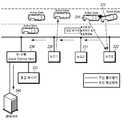
도 2는 본 발명의 일 실시예에 따른 교통정보 및 교통위급상황 전파 시스템의 개략적인 구성도이다.2 is a schematic block diagram of a traffic information and traffic emergency propagation system according to an embodiment of the present invention.
본 발명의 일 실시예에 따른 교통정보 및 교통위급상황 전파 시스템은 차량에 탑재된 텔레매틱스 단말기(210), 도로에 소정의 간격을 두고 설치된 센서노드(220~222), 도로의 일정 구획마다 설치되어 각 구획 내의 센서노드들과 센서 네트워크를 구성하는 국지제어유닛(Local Control Unit: LCU; 230) 및 각 구획별 국지제어유닛(230)으로부터 정보를 취합하는 관리서버(240)를 포함한다.The traffic information and traffic emergency situation propagation system according to an embodiment of the present invention includes a
텔레매틱스 단말기(210)는 차량에 장착되어, 차량내 OBD(ON-board Diagonsis) 단자로부터 차량상태정보를 수집하여 차량의 중대결함, 도로 상의 장애물, 교통사고 등과 같이 안전운전에 위험을 초래할 수 있는 위급상황의 발생 여부를 판단한다.The
여기서, 차량상태정보는 차량의 엔진제어장치, 변속제어장치(Transmission Control Unit: TCU), 현가제어장치, 제동제어장치 등의 차량 내 전자제어장치(Electronic Control Unit: ECU)가 검출 또는 진단한 자기 진단 정보로서 차량상태정보 및 주행상황정보를 포함할 수 있다. 예컨대 차량상태정보는 차량에 장착 또는 설치된 부품의 상태 또는 이상 유무 등을 말하며, 주행상황정보는 차량의 현재 주행 속도, 엔진 회전수, 최고 속도, 평균 속도, 주행 거리, 주행 시간 등의 주행 정보를 말한다.Here, the vehicle state information is information on the state of the vehicle, such as an engine control device, a transmission control unit (TCU), a suspension control device, a brake control device, and the like, which are detected or diagnosed by an electronic control unit And may include vehicle status information and running status information as diagnostic information. For example, the vehicle state information refers to the state or abnormality of a component installed or installed in the vehicle, and the running state information includes driving information such as the current driving speed, the engine speed, the maximum speed, the average speed, It says.
센서노드(220~222)는 도로변에 소정의 간격을 두고 복수 개가 배치된다. 센서노드간의 간격은 각 센서노드의 무선통신범위에 기초하여 결정될 수 있다. 각 센서노드는 고유한 센서노드 번호를 가질 수 있으며, 센서노드 번호는 국지제어유닛와 연결된 네트워크에서 각 센서노드(220~222)의 고유 식별자로서 기능할 수 있다. 센서노드(220~222)는 무선 데이터 정보를 주기적으로 송출하고 있다가 통신영역 내에 텔레매틱스 단말기가 진입하면 무선통신으로 정보 교환을 수행한다.A plurality of
센서노드(220~222)와 텔레매틱스 단말기(210) 사이의 통신은 WiFi, Wibro 등의 통신방식을 이용하여 이루어질 수 있다. 다만, 국지적으로 위치한 센서노드(220~222)와 고속으로 이동하는 차량에 탑재된 텔레매틱스 단말기(210) 간에 무선통신이 이루어져야 하는 본 실시예의 특성상, 정확도가 높고 순간적인 통신속도가 빠른 5.8 GHz 대역의 근거리 통신(Dedicated Short Range Communication; 이하 'DSRC'라고 약칭함) 방식을 이용하는 것이 바람직하다.Communication between the
국지제어유닛(230)는 도로의 일정 구획마다 설치되어 각 구획 내에 설치된 복수의 센서노드(220~222)와 관리서버(240) 사이에서 중계역할을 수행하며, 전광판(231)을 통해 해당 구획을 통행하는 운전자에게 교통정보 내지 위급상황정보를 제공할 수 있다.The
국지제어유닛(230)와 각 구획 내에 설치된 복수의 센서노드(220~222)는 유선통신을 기반으로 연결되어 센서 네트워크를 형성한다. 여기서 센서 네트워크의 기반이 되는 유선통신망은 이더넷(Ethernet) 통신망 또는 전용 통신망일 수 있다.The
관리서버(240)는 각 구획별로 설치된 국지제어유닛(230)들로부터 수집한 정보를 토대로 응급대응조치를 취하고, 교통정보를 생성하여 각 구획별 국지제어유닛에 분배한다. 교통정보는 교통소통정보, 교통통제정보, 위급상황정보, 도로상태정보 등을 포함할 수 있다. 여기서, 교통소통정보는 도로의 교통소통상황 및 교통예측상황을 나타내는 정보로서, 속도, 교통량, 통행시간, 대기길이, 정체도, 구간예측평균속도, 구간예측통과시간, 구간속도추이 등을 포함할 수 있으며, 교통통제정보는 미리 계획된 도로의 공사, 행사 등 교통의 통제상황을 나타내는 정보로서, 통제위치, 통제 유형, 통제 대상, 통제시간 등의 정보를 포함할 수 있다. 또한 위급상황정보는 예상하지 못한 도로상의 유고상황을 알려주는 정보로서, 위급상황발생정보, 위급상황처리요령 등의 정보를 포함할 수 있으며, 도로상태정보는 기상조건 및 돌발상황에 따른 도로의 상태를 나타내는 정보로서, 노면상태, 강우/강설 수위 등의 정보를 포함할 수 있다.The
이하에서는 도 3 및 도 4를 참조하여, 본 발명의 일 실시예에 따른 교통정보 및 교통위급상황정보 전파 시스템의 동작을 설명하기로 한다.Hereinafter, the operation of the traffic information and traffic emergency information propagation system according to an embodiment of the present invention will be described with reference to FIG. 3 and FIG.
도 3은 본 발명의 일 실시예에 따른 교통정보 및 교통위급상황정보 전파 시스템에서 차량의 도로 진출입시 동작을 예시한 도면이다.FIG. 3 is a diagram illustrating an operation of the vehicle when the vehicle enters and exits the road in the traffic information and traffic emergency information propagation system according to an embodiment of the present invention.
도 3에 도시된 바와 같이, 본 실시예에 따른 교통정보 및 위급상황정보 전파 시스템이 설치되어 작동하는 도로에 차량이 진입할 경우, 차량에 장착된 텔레매틱스 단말기(210)는 센서노드(220~222)로부터 주기적으로 송신되는 정보요청 메시지를 수신한다.3, when the vehicle enters the road where the traffic information and emergency situation information propagation system according to the present embodiment is installed and operated, the
정보요청 메시지에 대한 응답으로 차량에 장착된 텔레매틱스 단말기(210)는 차량 ID, 차량의 이동속도, 목적지 정보 등의 차량운행정보를 센서노드(220~222)에 전송한다. 여기서 차량 ID정보는 각 텔레매틱스 단말기(210)에 할당된 고유 ID일 수 있다. 센서노드(220~222)는 수신한 차량운행정보를 해당 구획의 국지제어유닛(230)에 전송한다. 국지제어유닛(220~222)는 수신한 차량운행정보를 관리서버(240)로 전송한다.In response to the information request message, the
관리서버(240)는 수신한 차량상태정보를 등록/저장하는 한편, 이를 기초로 교통정보(예컨대 교통소통정보, 교통통제정보, 위급상황정보, 도로상태정보 등)를 생성/갱신하고, 생성/갱신된 교통정보를 각 구획에 위치한 국지제어유닛(230)들에 전송한다.The
국지제어유닛(230)는 관리서버(240)로부터 수신한 교통정보를 해당 구획에 위치한 센서노드들(220~222)로 전송한다. 국지제어유닛(230)는 수신한 교통정보를 전광판(미도시)을 통해 해당 지점을 통행하는 차량의 운전자에게 제공할 수 있다.The
센서노드(220~222)는 국지제어유닛(230)로부터 수신한 교통정보를 무선통신 영역 내에 있는 텔레매틱스 단말기(210)들에 전파한다.The
텔레매틱스 단말기(210)는 센서노드(220~222)로부터 교통정보를 수신하여, 해당 교통정보를 운전자에게 제공한다.The
본 실시예에 따른 교통정보 및 교통위급상황 전파 시스템이 전개된 도로로부터 차량이 진출할 경우, 차량에 장착된 텔레매틱스 단말기(210)는 센서노드(220~222)로부터 주기적으로 송신되는 정보요청 메시지를 수신한다. 즉, 도로의 출구(예컨대 고속도로의 출구) 부근에 설치된 센서노드(220~222)는 차량의 이탈정보를 획득하기 위해 도로상에 정보요청 메시지를 주기적으로 브로드캐스트 (Broadcast)한다.When the vehicle is advanced from the road in which the traffic information and traffic emergency propagation system according to the present embodiment is deployed, the
정보요청 메시지에 대한 응답으로 텔레매틱스 단말기(210)는 차량 ID 정보를 센서노드(220~222)에 전송한다. 센서노드(220~222)는 수신한 차량 ID 정보를 해당구간을 담당하는 국지제어유닛(230)에 전송한다. 국지제어유닛(230)는 수신한 차량 ID 정보를 관리서버(미도시)로 전송하고, 관리서버(미도시)는 수신한 차량 ID 정보의 등록을 해제한다.In response to the information request message, the
도 4는 본 발명의 일 실시예에 따른 교통정보 및 교통위급상황 전파 시스템에서 위급상황 발생시 동작을 예시한 도면이다.4 is a diagram illustrating an operation in an emergency situation in a traffic information and traffic emergency situation propagation system according to an embodiment of the present invention.
텔레매틱스 단말기(210)가 차량내 OBD 단자로부터 수집한 차량상태정보를 기초로 차량의 중대결함, 도로 상의 장애물, 교통사고 등과 같이 안전운전에 위험을 초래할 수 있는 위급상황정보를 파악한 경우, 텔레매틱스 단말기(210)는 1차적으로 해당 정보를 화상, 음성 등을 통해 운전자에게 알리고, 차량의 비상등, 경적 등을 자동으로 작동시켜 근거리에 위치한 다른 차량의 운전자에게 위급상황 발생을 알린다. 또한 텔레매틱스 단말기(210)는 해당 차량의 ID, 목적지 정보, 위치 정보, 결함 정보 등을 포함한 응급메시지를 센서노드(222)로 전송한다.If the
텔레매틱스 단말기(210)로부터 응급메시지를 수신한 센서노드(222)는 수신한 응급메시지를 인접한 후방 센서노드(221) 및 국지제어유닛(230)로 전파한다. 후방 센서노드(221)는 연이어 자신의 후방 센서노드(220)에 수신한 응급메시지를 전파한다. 또한, 응급메시지를 수신한 센서노드들(221~222)은 2차 사고 방지 및 응급차량의 이동경로를 확보하기 위해 수신한 응급메시지를 도로 상에 브로드캐스트한다.The
즉, 텔레매틱스 단말기(210)으로부터 생성된 응급메시지는 이를 처음으로 수신한 센서노드(222)를 거쳐 후방의 센서노드들(221→220)로 차례로 전파되고, 각 센서노드들(220~222)에 의해 도로 상에 브로드캐스트되어 위급상황이 발생한 지점의 후방에서 주행중인 차량들에 순차적으로 전달된다.That is, the emergency message generated from the
응급 메시지를 수신한 국지제어유닛(230)는 현위치를 기준으로 사고지점까지의 거리 등의 정보를 전광판(231)에 표시하는 한편, 수신한 응급 메시지를 관리서버(240)에 전송한다.Upon receiving the emergency message, the
관리서버(240)는 수신한 응급메시지를 기반으로 응급대응조치(예컨대 경찰서, 보험사 등에 정보전송)를 취하는 한편, 사고지점의 후방 국지제어유닛들(미도시)에 위급상황정보를 전송한다.The
후방 국지제어유닛들은 현위치를 기준으로 사고지점까지의 거리 등의 정보를 전광판에 표시하는 한편, 자신의 구획 내에 위치한 센서노드들에게 위급상황정보를 전송한다. 위급상황정보를 수신한 센서노드들은 이를 도로 상에 브로드캐스트하며, 브로드캐스트된 위급상황정보를 수신한 텔레매틱스 단말기들은 해당 위급상황정보를 운전자에게 제공한다.The backward local control units display the information such as the distance to the point of incidence based on the current position on the electric signboard, and transmit the emergency information to the sensor nodes located in their own compartments. The sensor nodes that have received the emergency information broadcast it on the road, and the telematics terminals that received the broadcast emergency information provide the emergency information to the driver.
이하에서는 도 5 내지 도 7를 참조하여 본 발명의 일 실시예에 따른 교통정보 및 교통위급상황 전파 시스템에 포함된 텔레매틱스 단말기, 센서노드, 국지제어유닛의 개략적인 구성을 설명하기로 한다.Hereinafter, a schematic configuration of a telematics terminal, a sensor node, and a local control unit included in a traffic information and traffic emergency situation propagation system according to an embodiment of the present invention will be described with reference to FIG. 5 to FIG.
도 5는 본 발명의 일 실시예에 따른 텔레매틱스 단말기의 구성을 개략적으로 도시한 도면이다.FIG. 5 is a diagram schematically showing a configuration of a telematics terminal according to an embodiment of the present invention.
도 5에 도시된 바와 같이, 본 실시예에 따른 텔레매틱스 단말기(500)는 무선통신부(510), GPS 수신부(520), 정보 제공부(530), CAN 통신부(540) 및 단말기_제어부(550)를 포함한다.5, the
무선통신부(510)는 센서노드와 정보를 교환하기 위한 무선통신수단으로서, 예컨대 DSRC 통신을 지원할 수 있는 RF 모듈 및 RF 안테나로 구현될 수 있다.The
GPS 수신부(520)는 위성으로부터 송신되는 차량의 현재 위치 정보를 수신하여 제어부에 전송하며, GPS 수신모듈과 GPS 안테나를 포함한다.The
정보 제공부(530)는 운전자에게 교통정보 및 위급상황정보를 제공하기 위한 수단으로서, 화상 또는 음성을 지원하는 정보제공수단으로 구현될 수 있다.The
CAN 통신부(540)는 차량내 OBD 단자로부터 차량상태정보를 수집한다. 여기서, 차량상태정보는 차량의 엔진제어장치, 변속제어장치(TCU), 현가제어장치, 제동제어장치 등의 차량 내 전자제어장치(ECU)가 검출 또는 진단한 자기 진단 정보로서 차량상태정보 및 주행상황정보를 포함할 수 있다. 구체적으로 차량상태정보는 차량에 장착 또는 설치된 부품의 상태 또는 이상 유무 등에 관한 정보를 말하며, 주행상황정보는 차량의 현재 주행 속도, 엔진 회전수, 최고 속도, 평균 속도, 주행 거리, 주행 시간 등의 주행 정보를 말한다.The
단말기_제어부(550)는 텔레매틱스 단말기(500)의 각 부(510~540)의 제어를 총괄한다. 단말기_제어부(550)는 센서노드의 정보요청 메시지에 대한 응답으로 차량운행정보를 무선통신부(510)를 통해 센서노드에 전송한다. 차량운행정보는 GPS 수신부(520), CAN 통신부(540)를 통해 수집한 정보 또는 운전자로부터 입력받은 정보 등을 토대로 획득한 차량 ID(또는 텔레매틱스 단말기(500)의 고유 ID), 차량의 이동속도, 목적지 정보 등을 포함할 수 있다.The
또한, 단말기_제어부(550)는 CAN 통신부(540)를 통해 수집한 차량상태정보를 기초로 차량 부품의 중대결함이나 사고 발생 등을 포함한 위급상황 발생 여부를 모니터링한다. 위급상황이 발생한 것으로 판단한 경우, 단말기_제어부(550)는 1차적으로 정보 제공부(530)를 통해 위급상황정보를 운전자에게 알리고, 다른 차량의 운전자에게 위급상황이 발생하였음을 알리기 위해 CAN 통신부(540)를 통해 ECU를 제어하여 차량의 비상등, 경적 등을 동작시킨다. 또한 단말기_제어부(550)는 무선통신부(510)를 통해 위급상황정보를 센서노드로 전송한다.In addition, the
더불어, 단말기_제어부(550)는 센서노드로부터 주행하는 도로의 교통정보 및 타 차량의 위급상황정보를 수신하여 정보 제공부(530)를 통해 운전자에게 해당 정보를 제공할 수 있다.In addition, the
도 6은 본 발명의 일 실시예에 따른 센서노드의 구성을 개략적으로 도시한 도면이다.6 is a diagram schematically showing a configuration of a sensor node according to an embodiment of the present invention.
도 6에 도시된 바와 같이, 본 실시예에 따른 센서노드(600)는 무선통신부(610) 및 유선통신부(620) 및 센서노드_제어부(630)를 포함한다.6, the
무선통신부(610)는 차량에 장착된 텔레매틱스 단말기와 정보를 교환하기 위한 무선통신수단으로서, 예컨대 DSRC 통신을 지원할 수 있는 RF 모듈 및 RF 안테나로 구현될 수 있다.The
유선통신부(620)는 센서 네트워크에 연결되어 국지제어유닛 및 주변 센서노드와 통신하기 위한 유선통신수단으로서, 예컨대 TCP/IP 프로토콜 기반의 통신을 지원할 수 있다.The
센서노드_제어부(630)는 센서노드(600)의 각 부(610~620)의 제어를 총괄한다. 센서노드_제어부(630)는 무선통신부(610)를 통해 차량의 텔레매틱스 단말기로부터 차량운행정보를 수집하여 유선통신부(620)를 통해 국지제어유닛에 전송한다.The
센서노드_제어부(630)는 텔레매틱스 단말기로부터 위급상황정보를 수신하는 경우, 무선통신부(610)를 통해 해당 위급상황정보를 도로 상에 브로드캐스트하는 한편, 유선통신부(620)를 통해 주변 센서노드에 해당 위급상황정보를 전파한다. 또한 센서노드_제어부(630)는 유선통신부(620)를 통해 주변 센서노드로부터 위급상황정보를 수신할 수 있으며, 수신한 위급상황정보를 무선통신부(610)를 통해 도로 상에 브로드캐스트 할 수 있다.When receiving the emergency information from the telematics terminal, the
도 7은 본 발명의 일 실시예에 따른 국지제어유닛의 구성을 개략적으로 도시한 도면이다.FIG. 7 is a view schematically showing a configuration of a local control unit according to an embodiment of the present invention.
도 7에 도시된 바와 같이, 본 실시예에 따른 국지제어유닛(700)는 유선통신부(710), 전광판 구동부(720) 및 LCU_제어부(730)를 포함한다.7, the
유선통신부(710)는 센서 네트워크에 연결되어 해당 구역의 센서노드들 및 관리서버와 통신하기 위한 유선통신수단으로서, 예컨대 TCP/IP 프로토콜 기반의 통신을 지원할 수 있다.The
전광판 구동부(720)는 교통정보 또는 위급상황정보를 표시하기 위해 전광판을 구동하는 기능을 수행한다.The electric
LCU_제어부(730)는 센서노드의 각 부(710~720)의 제어를 총괄한다. LCU_제어부(730)는 유선통신부(710)를 통해 담당 구역의 센서노드들로부터 차량운행정보 및 위급상황정보를 수집하여, 해당 정보를 유선통신부(710)를 통해 국지제어유닛에 전송한다. 또한, LCU_제어부(730)는 수신한 교통위급상황정보를 기반으로 현 위치를 기준으로 사고지점까지의 거리 등의 정보를 전광판 구동부(720)를 통해 전광판에 표시한다.The
이상의 설명은 본 실시예의 기술 사상을 예시적으로 설명한 것에 불과한 것으로서, 본 실시예가 속하는 기술 분야에서 통상의 지식을 가진 자라면 본 실시예의 본질적인 특성에서 벗어나지 않는 범위에서 다양한 수정 및 변형이 가능할 것이다. 따라서, 본 실시예들은 본 실시예의 기술 사상을 한정하기 위한 것이 아니라 설명하기 위한 것이고, 이러한 실시예에 의하여 본 실시예의 기술 사상의 범위가 한정되는 것은 아니다. 본 실시예의 보호 범위는 아래의 청구범위에 의하여 해석되어야 하며, 그와 동등한 범위 내에 있는 모든 기술 사상은 본 실시예의 권리범위에 포함되는 것으로 해석되어야 할 것이다.The foregoing description is merely illustrative of the technical idea of the present embodiment, and various modifications and changes may be made to those skilled in the art without departing from the essential characteristics of the embodiments. Therefore, the present embodiments are to be construed as illustrative rather than restrictive, and the scope of the technical idea of the present embodiment is not limited by these embodiments. The scope of protection of the present embodiment should be construed according to the following claims, and all technical ideas within the scope of equivalents thereof should be construed as being included in the scope of the present invention.
210: 텔레매틱스 단말기220~222: 센서노드
230: 국지제어유닛231: 전광판
240: 관리서버500: 텔레매틱스 단말기
510: 무선통신부520: GPS 수신부
530: 정보 제공부540: CAN 통신부
550: 단말기_제어부600: 센서노드
610: 무선통신부620: 유선통신부
630: 센서노드_제어부700: 국지제어유닛
710: 유선통신부720: 전광판 구동부
730: LCU_제어부210: Telematics terminal 220-222: Sensor node
230: Local control unit 231:
240: management server 500: telematics terminal
510: wireless communication unit 520: GPS receiver
530: Information providing unit 540: CAN communication unit
550: Terminal_controller 600: Sensor node
610: wireless communication unit 620: wired communication unit
630: Sensor node_ control unit 700: Local control unit
710: wire communication unit 720:
730: LCU_controller
Claims (16)
Translated fromKorean도로에 소정의 간격으로 설치되어, 차량에 장착된 텔레매틱스 단말기로부터 위급상황정보를 수신하고, 수신한 상기 위급상황정보를 주변의 타 센서노드 및 주변 차량에 전파하는 복수의 센서노드;
상기 도로의 일정 구획마다 설치되어, 각 구획 내에 설치된 상기 센서노드로부터 상기 위급상황정보를 수신하고, 수신한 상기 위급상황정보를 전광판에 표시하는 복수의 국지제어유닛(Local Control Unit: LCU); 및
상기 복수의 국지제어유닛으로부터 상기 위급상황정보를 수신하고, 수신한 상기 위급상황정보에 대응하여 소정의 대응조치를 수행하는 관리서버
를 포함하되,
상기 복수의 센서노드는 상기 텔레매틱스 단말기로부터 수신한 위급상황정보를 주변의 타 센서노드에 전파함에 있어서, 상기 국지제어유닛 및 상기 관리서버를 거치지 않고 직접 전파하는 것을 특징으로 하는 교통정보 및 교통위급상황정보 전파 시스템.In a traffic information and traffic emergency information propagation system,
A plurality of sensor nodes installed at predetermined intervals on a road to receive emergency situation information from a telematics terminal mounted on a vehicle and to propagate the emergency information to nearby other sensor nodes and surrounding vehicles;
A plurality of local control units (LCUs) installed for each predetermined section of the road, receiving the emergency information from the sensor node installed in each of the sections, and displaying the received emergency information on the electric signboard; And
A management server for receiving the emergency information from the plurality of local control units and performing a predetermined countermeasure in response to the received emergency information,
, ≪ / RTI &
Wherein the plurality of sensor nodes directly propagate the emergency information received from the telematics terminal to another sensor node in the vicinity without going through the local control unit and the management server. Information propagation system.
상기 복수의 센서노드는,
근거리 통신 방식을 기반으로 상기 텔레매틱스 단말과 통신을 수행하는 것을 특징으로 하는 교통정보 및 교통위급상황정보 전파 시스템.The method according to claim 1,
Wherein the plurality of sensor nodes comprise:
And communicates with the telematics terminal based on the short distance communication method.
상기 복수의 센서노드는,
상기 근거리 통신 방식의 통신범위에 기초하여 결정된 소정의 간격으로 도로변에 설치된 것을 특징으로 하는 교통정보 및 교통위급상황정보 전파 시스템.3. The method of claim 2,
Wherein the plurality of sensor nodes comprise:
Wherein the traffic information is provided on the road at a predetermined interval determined based on the communication range of the local area communication system.
상기 복수의 센서노드는,
상기 텔레매틱스 단말기로부터 수신한 상기 위급상황정보 및 상기 주변의 타 센서노드로부터 수신한 위급상황정보를 도로 상에 브로트캐스트(Broadcast) 방식으로 전파하는 것을 특징으로 하는 교통정보 및 교통위급상황정보 전파 시스템.The method according to claim 1,
Wherein the plurality of sensor nodes comprise:
Wherein the emergency information received from the telematics terminal and the emergency information received from the neighboring sensor node are broadcast on the road in a broadcast manner.
상기 관리서버는,
상기 위급상황정보를 관련 유관기관 및 상기 도로의 각 구획별로 설치된 상기 국지제어유닛에 전파하는 것을 특징으로 하는 교통정보 및 교통위급상황정보 전파 시스템.The method according to claim 1,
The management server includes:
And the emergency situation information is propagated to the relevant control center and the local control unit provided for each section of the road.
상기 국지제어유닛은,
상기 관리서버로부터 수신한 상기 위급상황정보를 자신의 구획 내에 설치된 상기 센서노드들에 전파하는 것을 특징으로 하는 교통정보 및 교통위급상황정보 전파 시스템.6. The method of claim 5,
Wherein the local control unit comprises:
And the emergency information received from the management server is propagated to the sensor nodes installed in the compartment of the vehicle.
상기 센서노드들은
상기 국지제어유닛으로부터 수신한 상기 위급상황정보를 주변 차량에 전파하는 것을 특징으로 하는 교통정보 및 교통위급상황정보 전파 시스템.The method according to claim 6,
The sensor nodes
And the emergency situation information received from the local control unit is propagated to the neighboring vehicle.
차량의 OBD(ON-board Diagonsis) 단자로부터 CAN(Controller Area Network) 통신을 통해 차량상태정보를 수집하기 위한 CAN 통신부;
상기 교통정보 및 교통위급상황정보 전파 시스템의 센서 노드와 통신을 수행하기 위한 무선통신부;
위성으로부터 송신되는 상기 차량의 위치 정보를 수신하기 위한 GPS 수신부;
상기 차량의 운전자에게 교통정보 및 위급상황정보를 제공하기 위한 정보 제공부; 및
상기 CAN 통신부가 수집한 상기 차량상태정보를 기초로 위급상황 발생 여부를 모니터링하여, 상기 차량의 위치 정보와 함께 감지된 위급상황정보를 상기 무선통신부를 통해 상기 센서 노드에 전송하는 제어부
를 포함하되,
상기 제어부는,
상기 감지된 위급상황정보를 상기 정보 제공부를 통해 상기 차량의 운전자에게 제공하고, 상기 CAN 통신부를 통해 상기 차량 내부의 전자제어장치(Electronic Control Unit: ECU)를 제어하여 상기 차량의 비상등 또는 경적 중 적어도 어느 하나를 동작시킴으로써 주변의 타 차량의 운전자에게 경고하는 것을 특징으로 하는 교통정보 및 교통위급상황정보 전파 시스템의 텔레매틱스 단말기.A telematics terminal for traffic information and traffic emergency information propagation system,
A CAN communication unit for collecting vehicle status information through CAN (Controller Area Network) communication from an OBD (ON-board Diagonsis) terminal of the vehicle;
A wireless communication unit for communicating with the sensor node of the traffic information and traffic emergency information propagation system;
A GPS receiver for receiving position information of the vehicle transmitted from a satellite;
An information providing unit for providing traffic information and emergency information to the driver of the vehicle; And
A controller for monitoring occurrence of an emergency situation on the basis of the vehicle state information collected by the CAN communication unit and transmitting the emergency state information sensed together with the vehicle position information to the sensor node through the wireless communication unit,
, ≪ / RTI &
Wherein,
And provides the detected emergency information to the driver of the vehicle through the information providing unit and controls an electronic control unit (ECU) in the vehicle through the CAN communication unit to detect at least one of the emergency light or horn of the vehicle Wherein the warning is issued to the driver of the other vehicle by operating any one of the plurality of traffic information and traffic emergency information.
상기 제어부는,
상기 무선통신부를 통해 상기 센서노드로부터 도로 상에 발생한 교통정보 및 위급상황정보를 수신하여 상기 정보 제공부를 통해 상기 차량의 운전자에게 제공하는 것을 특징으로 하는 교통정보 및 교통위급상황정보 전파 시스템의 텔레매틱스 단말기.12. The method of claim 11,
Wherein,
The traffic information and the emergency information generated on the road from the sensor node through the wireless communication unit and provides the traffic information and the emergency situation information to the driver of the vehicle through the information providing unit. .
상기 무선통신부는,
근거리 통신 방식을 기반으로 상기 센서 노드와 통신을 수행하는 것을 특징으로 하는 교통정보 및 교통위급상황정보 전파 시스템의 텔레매틱스 단말기.12. The method of claim 11,
The wireless communication unit includes:
And communicating with the sensor node based on the local communication method. The telematics terminal of the traffic information and traffic emergency information propagation system.
차량에 장착되어, 상기 차량의 OBD 단자로부터 CAN 통신을 통해 수집한 차량상태정보를 기초로 위급상황 발생 여부를 모니터링하는 텔레매틱스 단말기;
상기 텔레매틱스 단말기로부터 위급상황정보를 수신하고, 수신한 상기 위급상황정보를 주변의 타 센서노드 및 주변 차량에 전파하기 위해, 도로에 소정의 간격으로 설치된 복수의 센서노드;
상기 도로의 일정 구획마다 설치되어, 각 구획 내에 설치된 상기 센서노드로부터 상기 위급상황정보를 수신하고, 수신한 상기 위급상황정보를 전광판에 표시하는 복수의 국지제어유닛; 및
상기 복수의 국지제어유닛으로부터 상기 위급상황정보를 수신하고, 수신한 상기 위급상황정보에 대응하여 소정의 대응조치를 수행하는 관리서버
를 포함하되,
상기 복수의 센서노드는 상기 텔레매틱스 단말기로부터 수신한 위급상황정보를 주변의 타 센서노드에 전파함에 있어서, 상기 국지제어유닛 및 상기 관리서버를 거치지 않고 직접 전파하는 것을 특징으로 하는 교통정보 및 교통위급상황정보 전파 시스템.In a traffic information and traffic emergency information propagation system,
A telematics terminal mounted on a vehicle and monitoring whether an emergency situation occurs based on vehicle state information collected through CAN communication from an OBD terminal of the vehicle;
A plurality of sensor nodes installed on the road at predetermined intervals in order to receive the emergency information from the telematics terminal and to propagate the emergency information to the other sensor nodes and the surrounding vehicles in the vicinity;
A plurality of local control units provided for each predetermined section of the road, receiving the emergency information from the sensor node installed in each of the sections, and displaying the received emergency information on the electric signboard; And
A management server for receiving the emergency information from the plurality of local control units and performing a predetermined countermeasure in response to the received emergency information,
, ≪ / RTI &
Wherein the plurality of sensor nodes directly propagate the emergency information received from the telematics terminal to another sensor node in the vicinity without going through the local control unit and the management server. Information propagation system.
Priority Applications (1)
| Application Number | Priority Date | Filing Date | Title |
|---|---|---|---|
| KR1020120116910AKR101439171B1 (en) | 2012-10-19 | 2012-10-19 | System and Apparatus for Transmitting Traffic Information and Emergency Information Using Vehicle-Roadside Communications |
Applications Claiming Priority (1)
| Application Number | Priority Date | Filing Date | Title |
|---|---|---|---|
| KR1020120116910AKR101439171B1 (en) | 2012-10-19 | 2012-10-19 | System and Apparatus for Transmitting Traffic Information and Emergency Information Using Vehicle-Roadside Communications |
Publications (2)
| Publication Number | Publication Date |
|---|---|
| KR20140050462A KR20140050462A (en) | 2014-04-29 |
| KR101439171B1true KR101439171B1 (en) | 2014-09-11 |
Family
ID=50655632
Family Applications (1)
| Application Number | Title | Priority Date | Filing Date |
|---|---|---|---|
| KR1020120116910AExpired - Fee RelatedKR101439171B1 (en) | 2012-10-19 | 2012-10-19 | System and Apparatus for Transmitting Traffic Information and Emergency Information Using Vehicle-Roadside Communications |
Country Status (1)
| Country | Link |
|---|---|
| KR (1) | KR101439171B1 (en) |
Cited By (1)
| Publication number | Priority date | Publication date | Assignee | Title |
|---|---|---|---|---|
| KR20230093845A (en) | 2021-12-20 | 2023-06-27 | 한국도로공사 | System for V2X communication of vehicles driving in tunnels and method for changing channels using the same |
Families Citing this family (4)
| Publication number | Priority date | Publication date | Assignee | Title |
|---|---|---|---|---|
| KR101617543B1 (en) | 2014-10-06 | 2016-05-02 | 주식회사 만도 | Detecting system for vehicle emergency |
| KR102711653B1 (en)* | 2019-12-04 | 2024-10-02 | 한국전자통신연구원 | Wired and wireless communication net work system and message process method for providing traffic safety service |
| KR102244844B1 (en)* | 2020-11-18 | 2021-04-27 | 한국건설기술연구원 | Lane regulation rod with screw type corrugated pipe |
| US11516636B2 (en)* | 2021-01-29 | 2022-11-29 | GM Global Technology Operations LLC | Latency masking in an autonomous vehicle using edge network computing resources |
Citations (4)
| Publication number | Priority date | Publication date | Assignee | Title |
|---|---|---|---|---|
| KR20060083027A (en)* | 2005-01-14 | 2006-07-20 | (주)하이게인안테나 | Multifunctional Integrated Vehicle Mounting Terminal for Active Short-range Dedicated Communication Network |
| KR20110010953A (en)* | 2009-07-27 | 2011-02-08 | 조용성 | Traffic accident guidance system and guidance |
| KR101049940B1 (en) | 2010-04-30 | 2011-07-15 | 경북대학교 산학협력단 | How to send messages and how to send multihop messages in ubiquitous traffic sensor networks |
| KR20120064938A (en)* | 2010-12-10 | 2012-06-20 | 주식회사 케이티 | Method and apparatus for collecting and transmitting emergency information based on anycast-multicast communication |
- 2012
- 2012-10-19KRKR1020120116910Apatent/KR101439171B1/ennot_activeExpired - Fee Related
Patent Citations (4)
| Publication number | Priority date | Publication date | Assignee | Title |
|---|---|---|---|---|
| KR20060083027A (en)* | 2005-01-14 | 2006-07-20 | (주)하이게인안테나 | Multifunctional Integrated Vehicle Mounting Terminal for Active Short-range Dedicated Communication Network |
| KR20110010953A (en)* | 2009-07-27 | 2011-02-08 | 조용성 | Traffic accident guidance system and guidance |
| KR101049940B1 (en) | 2010-04-30 | 2011-07-15 | 경북대학교 산학협력단 | How to send messages and how to send multihop messages in ubiquitous traffic sensor networks |
| KR20120064938A (en)* | 2010-12-10 | 2012-06-20 | 주식회사 케이티 | Method and apparatus for collecting and transmitting emergency information based on anycast-multicast communication |
Cited By (1)
| Publication number | Priority date | Publication date | Assignee | Title |
|---|---|---|---|---|
| KR20230093845A (en) | 2021-12-20 | 2023-06-27 | 한국도로공사 | System for V2X communication of vehicles driving in tunnels and method for changing channels using the same |
Also Published As
| Publication number | Publication date |
|---|---|
| KR20140050462A (en) | 2014-04-29 |
Similar Documents
| Publication | Publication Date | Title |
|---|---|---|
| US7609174B2 (en) | Vehicle information communication system | |
| US7324893B2 (en) | Traffic management system | |
| DE102010012402B4 (en) | Use V2X-based in-network message generation, message federation, message distribution, and message processing protocols to enable road hazard alert applications | |
| US7804423B2 (en) | Real time traffic aide | |
| CN107545756B (en) | Method for determining coordinated and/or autonomous driving common environmental information and vehicle | |
| JP6370942B2 (en) | Transmission equipment | |
| KR101439171B1 (en) | System and Apparatus for Transmitting Traffic Information and Emergency Information Using Vehicle-Roadside Communications | |
| KR100835385B1 (en) | System and method for reporting a car accident using a telematics device | |
| US20060178814A1 (en) | Method of, and system for, assessing the nature of movement of articles along a path of movement | |
| CN106297343A (en) | Front truck road conditions display system and method | |
| KR102011598B1 (en) | Emergency traffic control system using mobile device | |
| JP4354292B2 (en) | Inter-vehicle communication system, wireless communication device, and inter-vehicle communication method | |
| CN105407170A (en) | Internet of vehicles system with link protection | |
| JP2007297013A (en) | Risk avoidance system and risk avoidance method using narrow band two-way communication device | |
| CN113938860A (en) | Method, device and system for sending message and computer readable storage medium | |
| JP4835393B2 (en) | Road-to-vehicle communication determination system and method, and determination device used therefor | |
| KR20190048169A (en) | Emergency situation notification system | |
| JP5024108B2 (en) | Radio base station apparatus and driving support method | |
| JP2006166307A (en) | Narrow area communication device and narrow area communication system | |
| JP6847587B2 (en) | Reverse drive detection roadside device | |
| JP2008109210A (en) | Road-to-vehicle communication determination system and method, determination apparatus and vehicle-mounted device used therefor | |
| JP2014090237A (en) | Radio communication system, roadside communication apparatus for use therefor, communication control device, computer program, and communication method | |
| JP2004251710A (en) | Traffic information providing system and traffic information providing method | |
| US20250267599A1 (en) | Monitoring, detecting, estimating, and alerting the cv2x-pc5 operation status | |
| WO2012156773A1 (en) | Speed variation monitoring system and communication method thereof |
Legal Events
| Date | Code | Title | Description |
|---|---|---|---|
| A201 | Request for examination | ||
| PA0109 | Patent application | St.27 status event code:A-0-1-A10-A12-nap-PA0109 | |
| PA0201 | Request for examination | St.27 status event code:A-1-2-D10-D11-exm-PA0201 | |
| D13-X000 | Search requested | St.27 status event code:A-1-2-D10-D13-srh-X000 | |
| D14-X000 | Search report completed | St.27 status event code:A-1-2-D10-D14-srh-X000 | |
| E902 | Notification of reason for refusal | ||
| PE0902 | Notice of grounds for rejection | St.27 status event code:A-1-2-D10-D21-exm-PE0902 | |
| PN2301 | Change of applicant | St.27 status event code:A-3-3-R10-R13-asn-PN2301 St.27 status event code:A-3-3-R10-R11-asn-PN2301 | |
| T11-X000 | Administrative time limit extension requested | St.27 status event code:U-3-3-T10-T11-oth-X000 | |
| AMND | Amendment | ||
| E13-X000 | Pre-grant limitation requested | St.27 status event code:A-2-3-E10-E13-lim-X000 | |
| P11-X000 | Amendment of application requested | St.27 status event code:A-2-2-P10-P11-nap-X000 | |
| P13-X000 | Application amended | St.27 status event code:A-2-2-P10-P13-nap-X000 | |
| PG1501 | Laying open of application | St.27 status event code:A-1-1-Q10-Q12-nap-PG1501 | |
| E601 | Decision to refuse application | ||
| PE0601 | Decision on rejection of patent | St.27 status event code:N-2-6-B10-B15-exm-PE0601 | |
| AMND | Amendment | ||
| E13-X000 | Pre-grant limitation requested | St.27 status event code:A-2-3-E10-E13-lim-X000 | |
| P11-X000 | Amendment of application requested | St.27 status event code:A-2-2-P10-P11-nap-X000 | |
| P13-X000 | Application amended | St.27 status event code:A-2-2-P10-P13-nap-X000 | |
| PX0901 | Re-examination | St.27 status event code:A-2-3-E10-E12-rex-PX0901 | |
| PX0701 | Decision of registration after re-examination | St.27 status event code:A-3-4-F10-F13-rex-PX0701 | |
| X701 | Decision to grant (after re-examination) | ||
| GRNT | Written decision to grant | ||
| PR0701 | Registration of establishment | St.27 status event code:A-2-4-F10-F11-exm-PR0701 | |
| PR1002 | Payment of registration fee | St.27 status event code:A-2-2-U10-U11-oth-PR1002 Fee payment year number:1 | |
| PG1601 | Publication of registration | St.27 status event code:A-4-4-Q10-Q13-nap-PG1601 | |
| R18-X000 | Changes to party contact information recorded | St.27 status event code:A-5-5-R10-R18-oth-X000 | |
| P22-X000 | Classification modified | St.27 status event code:A-4-4-P10-P22-nap-X000 | |
| P22-X000 | Classification modified | St.27 status event code:A-4-4-P10-P22-nap-X000 | |
| FPAY | Annual fee payment | Payment date:20170828 Year of fee payment:4 | |
| PR1001 | Payment of annual fee | St.27 status event code:A-4-4-U10-U11-oth-PR1001 Fee payment year number:4 | |
| P22-X000 | Classification modified | St.27 status event code:A-4-4-P10-P22-nap-X000 | |
| R18-X000 | Changes to party contact information recorded | St.27 status event code:A-5-5-R10-R18-oth-X000 | |
| FPAY | Annual fee payment | Payment date:20180823 Year of fee payment:5 | |
| PR1001 | Payment of annual fee | St.27 status event code:A-4-4-U10-U11-oth-PR1001 Fee payment year number:5 | |
| FPAY | Annual fee payment | Payment date:20190902 Year of fee payment:6 | |
| PR1001 | Payment of annual fee | St.27 status event code:A-4-4-U10-U11-oth-PR1001 Fee payment year number:6 | |
| PR1001 | Payment of annual fee | St.27 status event code:A-4-4-U10-U11-oth-PR1001 Fee payment year number:7 | |
| PR1001 | Payment of annual fee | St.27 status event code:A-4-4-U10-U11-oth-PR1001 Fee payment year number:8 | |
| PN2301 | Change of applicant | St.27 status event code:A-5-5-R10-R11-asn-PN2301 | |
| PN2301 | Change of applicant | St.27 status event code:A-5-5-R10-R14-asn-PN2301 | |
| PR1001 | Payment of annual fee | St.27 status event code:A-4-4-U10-U11-oth-PR1001 Fee payment year number:9 | |
| PR1001 | Payment of annual fee | St.27 status event code:A-4-4-U10-U11-oth-PR1001 Fee payment year number:10 | |
| PC1903 | Unpaid annual fee | St.27 status event code:A-4-4-U10-U13-oth-PC1903 Not in force date:20240903 Payment event data comment text:Termination Category : DEFAULT_OF_REGISTRATION_FEE | |
| PC1903 | Unpaid annual fee | St.27 status event code:N-4-6-H10-H13-oth-PC1903 Ip right cessation event data comment text:Termination Category : DEFAULT_OF_REGISTRATION_FEE Not in force date:20240903 |