KR101438888B1 - Apparatus for transmitting wireless power and system for transmitting wireless power - Google Patents
Apparatus for transmitting wireless power and system for transmitting wireless powerDownload PDFInfo
- Publication number
- KR101438888B1 KR101438888B1KR1020120060781AKR20120060781AKR101438888B1KR 101438888 B1KR101438888 B1KR 101438888B1KR 1020120060781 AKR1020120060781 AKR 1020120060781AKR 20120060781 AKR20120060781 AKR 20120060781AKR 101438888 B1KR101438888 B1KR 101438888B1
- Authority
- KR
- South Korea
- Prior art keywords
- transmission
- substrate
- power
- wireless power
- coil
- Prior art date
- Legal status (The legal status is an assumption and is not a legal conclusion. Google has not performed a legal analysis and makes no representation as to the accuracy of the status listed.)
- Expired - Fee Related
Links
Images


Classifications
- H—ELECTRICITY
- H02—GENERATION; CONVERSION OR DISTRIBUTION OF ELECTRIC POWER
- H02J—CIRCUIT ARRANGEMENTS OR SYSTEMS FOR SUPPLYING OR DISTRIBUTING ELECTRIC POWER; SYSTEMS FOR STORING ELECTRIC ENERGY
- H02J50/00—Circuit arrangements or systems for wireless supply or distribution of electric power
- H02J50/10—Circuit arrangements or systems for wireless supply or distribution of electric power using inductive coupling
- H02J50/12—Circuit arrangements or systems for wireless supply or distribution of electric power using inductive coupling of the resonant type
- H—ELECTRICITY
- H02—GENERATION; CONVERSION OR DISTRIBUTION OF ELECTRIC POWER
- H02J—CIRCUIT ARRANGEMENTS OR SYSTEMS FOR SUPPLYING OR DISTRIBUTING ELECTRIC POWER; SYSTEMS FOR STORING ELECTRIC ENERGY
- H02J50/00—Circuit arrangements or systems for wireless supply or distribution of electric power
- H02J50/70—Circuit arrangements or systems for wireless supply or distribution of electric power involving the reduction of electric, magnetic or electromagnetic leakage fields
- H—ELECTRICITY
- H02—GENERATION; CONVERSION OR DISTRIBUTION OF ELECTRIC POWER
- H02J—CIRCUIT ARRANGEMENTS OR SYSTEMS FOR SUPPLYING OR DISTRIBUTING ELECTRIC POWER; SYSTEMS FOR STORING ELECTRIC ENERGY
- H02J50/00—Circuit arrangements or systems for wireless supply or distribution of electric power
- H02J50/90—Circuit arrangements or systems for wireless supply or distribution of electric power involving detection or optimisation of position, e.g. alignment
- H—ELECTRICITY
- H04—ELECTRIC COMMUNICATION TECHNIQUE
- H04B—TRANSMISSION
- H04B5/00—Near-field transmission systems, e.g. inductive or capacitive transmission systems
- H04B5/20—Near-field transmission systems, e.g. inductive or capacitive transmission systems characterised by the transmission technique; characterised by the transmission medium
- H04B5/24—Inductive coupling
- H—ELECTRICITY
- H04—ELECTRIC COMMUNICATION TECHNIQUE
- H04B—TRANSMISSION
- H04B5/00—Near-field transmission systems, e.g. inductive or capacitive transmission systems
- H04B5/70—Near-field transmission systems, e.g. inductive or capacitive transmission systems specially adapted for specific purposes
- H04B5/79—Near-field transmission systems, e.g. inductive or capacitive transmission systems specially adapted for specific purposes for data transfer in combination with power transfer
Landscapes
- Engineering & Computer Science (AREA)
- Computer Networks & Wireless Communication (AREA)
- Power Engineering (AREA)
- Signal Processing (AREA)
- Physics & Mathematics (AREA)
- Electromagnetism (AREA)
- Charge And Discharge Circuits For Batteries Or The Like (AREA)
Abstract
Translated fromKoreanDescription
Translated fromKorean본 발명은 무선전력 전송 기술에 관한 것이다. 보다 상세하게는, 무선전력 송신장치의 구조를 개선하여 전력 전송 효율을 증가시킬 수 있는 무선전력 송신장치 및 무선전력 전송 시스템에 관한 것이다.The present invention relates to wireless power transmission techniques. More particularly, the present invention relates to a wireless power transmission apparatus and a wireless power transmission system capable of improving a structure of a wireless power transmission apparatus to increase power transmission efficiency.
무선으로 전기 에너지를 원하는 기기로 전달하는 무선전력전송 기술(wireless power transmission 또는 wireless energy transfer)은 이미 1800년대에 전자기유도 원리를 이용한 전기 모터나 변압기가 사용되기 시작했고, 그 후로는 라디오파나 레이저와 같은 전자파를 방사해서 전기에너지를 전송하는 방법도 시도 되었다. 우리가 흔히 사용하는 전동칫솔이나 일부 무선면도기도 실상은 전자기유도 원리로 충전된다. 전자기 유도는 도체의 주변에서 자기장을 변화시켰을 때 전압이 유도되어 전류가 흐르는 현상을 말한다. 전자기 유도 방식은 소형 기기를 중심으로 상용화가 빠르게 진행되고 있으나, 전력의 전송 거리가 짧은 문제가 있다.In the 1800s, electric motors and transformers using electromagnetic induction principles began to be used, and then radio waves and lasers were used to transmit the electric energy to the desired devices wirelessly. A method of transmitting electrical energy by radiating the same electromagnetic wave has also been attempted. Our electric toothbrushes and some wireless shavers are actually charged with electromagnetic induction. Electromagnetic induction is a phenomenon in which a voltage is induced and a current flows when a magnetic field is changed around a conductor. The electromagnetic induction method is rapidly commercialized mainly in small-sized devices, but there is a problem in that the transmission distance of electric power is short.
현재까지 무선 방식에 의한 에너지 전달 방식은 전자기 유도 이외에 공진및 단파장 무선 주파수를 이용한 원거리 송신 기술 등이 있다.Up to now, the energy transmission method using a wireless method includes a resonance method in addition to electromagnetic induction and a remote transmission technique using a short wavelength radio frequency.
최근에는 이와 같은 무선 전력 전송 기술 중 자기 공진을 이용한 에너지 전달 방식이 많이 사용되고 있다.In recent years, among such wireless power transmission techniques, energy transmission using self resonance is widely used.
자기 공진을 이용한 무선전력 전송 시스템은 송신 측과 수신 측에 형성된 전기신호가 코일을 통해 무선으로 전달되기 때문에 사용자는 휴대용 기기와 같은 전자기기를 손쉽게 충전할 수 있다.In the wireless power transmission system using self-resonance, since the electric signals formed on the transmission side and the reception side are wirelessly transmitted through the coil, the user can easily charge electronic devices such as portable devices.
그러나, 종래에는 송신 측과 수신 측 간 품질지수(Q: Quality factor) 및 전력 전송 효율을 높이는데 한계가 있었다.However, conventionally, there has been a limit in increasing the quality factor (Q) and power transmission efficiency between the transmitting side and the receiving side.
본 발명은 무선전력 송신장치와 무선전력 수신장치 간 전력 전송 효율을 극대화시킬 수 있는 무선전력 송신장치 및 무선전력 전송 시스템의 제공을 목적으로 한다.An object of the present invention is to provide a wireless power transmission apparatus and a wireless power transmission system capable of maximizing power transmission efficiency between a wireless power transmission apparatus and a wireless power reception apparatus.
본 발명은 무선전력 송신장치의 구성요소 간 배치간격을 조절하여 전력 전송 효율을 극대화시킬 수 있는 무선전력 송신장치 및 무선전력 전송 시스템의 제공을 목적으로 한다.An object of the present invention is to provide a wireless power transmission apparatus and a wireless power transmission system capable of maximizing a power transmission efficiency by adjusting the arrangement interval between components of a wireless power transmission apparatus.
본 발명은 무선전력 송신장치의 제1 기판과 제2 기판의 배치를 통해 전력 전송 효율을 극대화시킬 수 있는 무선전력 송신장치 및 무선전력 전송 시스템의 제공을 목적으로 한다.An object of the present invention is to provide a wireless power transmission apparatus and a wireless power transmission system capable of maximizing power transmission efficiency through arrangement of a first substrate and a second substrate of a wireless power transmission apparatus.
본 발명은 송신 공진 코일을 일정한 각도를 갖도록 배치하여 전력 전송 효율을 높일 수 있는 무선전력 송신장치 및 무선전력 전송 시스템의 제공을 목적으로 한다.An object of the present invention is to provide a wireless power transmission apparatus and a wireless power transmission system capable of increasing power transmission efficiency by disposing a transmission resonance coil at a certain angle.
본 발명의 실시 예에 따른 무선전력 수신장치에 무선으로 전력을 전송하는 무선전력 송신장치는 전원 공급부와 상기 전원 공급부와 연결된 송신 유도 코일 및 상기 송신 유도 코일과 유도 결합되어 전달받은 전력을 공진을 이용하여 상기 무선전력 수신장치에 전송하는 송신 공진 코일을 포함하며, 상기 송신 공진 코일은 수평면과 일정한 각도를 갖도록 기울어져 배치된 것을 특징으로 한다.A wireless power transmission apparatus for wirelessly transmitting power to a wireless power receiving apparatus according to an exemplary embodiment of the present invention includes a power supply unit, a transmission induction coil connected to the power supply unit, And a transmitting resonant coil for transmitting the transmitting resonant coil to the wireless power receiving apparatus, wherein the transmitting resonant coil is inclined to have a certain angle with the horizontal plane.
상기 송신 공진 코일은 일 측이 사용하고자 하는 충전 영역으로 기설정된 각도를 갖도록 기울어져 배치되는 것을 특징으로 한다.And the transmission resonance coil is arranged so that one side thereof is inclined to have a predetermined angle to a charging region to be used.
상기 일정한 각도는 0.1도 내지 30도의 범위를 갖는 것을 특징으로 한다.And the constant angle is in the range of 0.1 to 30 degrees.
상기 무선전력 송신장치는 상기 전원 공급부로부터 공급된 전력을 공진을 위한 주파수를 가지는 전력으로 변환하는 송신 회로부를 더 포함하고, 상기 송신 회로부는 상기 송신 공진 코일과 수직으로 이격하여 배치된 것을 특징으로 한다.The wireless power transmission apparatus may further include a transmission circuit unit that converts power supplied from the power supply unit to power having a frequency for resonance, and the transmission circuit unit is disposed so as to be vertically spaced from the transmission resonance coil .
상기 송신 회로부와 상기 송신 공진 코일의 수직거리는 0.1mm 내지 25mm 범위를 갖는 것을 특징으로 한다.And the vertical distance between the transmission circuit and the transmission resonance coil ranges from 0.1 mm to 25 mm.
상기 무선전력 송신장치는 상기 송신 유도 코일을 배치하기 위한 제1 기판 및 상기 제1 기판과 수직으로 이격되고, 상기 송신 회로부를 배치하기 위한 제2 기판을 더 포함하는 것을 특징으로 한다.The wireless power transmission apparatus may further include a first substrate for disposing the transmission induction coil, and a second substrate spaced vertically from the first substrate and for disposing the transmission circuit.
상기 송신 공진 코일은 동축 나선형의 구조이고, 상기 제2 기판은 윗면이 개방된 원통형의 구조인 것을 특징으로 한다.The transmission resonance coil is a coaxial spiral structure, and the second substrate is a cylindrical structure with an open top surface.
상기 제2 기판의 밑면 지름과 상기 송신 공진 코일이 형성하는 지름의 비율은 3:8인 것을 특징으로 한다.And a ratio of a bottom diameter of the second substrate to a diameter of the transmission resonance coil is 3: 8.
상기 무선전력 송신장치는 상기 전원 공급부로부터 전원을 공급받아 상기 송신 회로부로 전달하는 전원 연결부를 더 포함하는 것을 특징으로 한다.The wireless power transmission apparatus may further include a power connection unit that receives power from the power supply unit and transmits the power to the transmission circuit unit.
상기 전원 연결부는 상기 제1 기판 위에 배치되는 것을 특징으로 한다.And the power connection part is disposed on the first substrate.
상기 제1 기판 및 제2 기판은 인쇄회로기판인 것을 특징으로 한다.The first substrate and the second substrate are printed circuit boards.
상기 제1 기판은 원형의 형태이고, 상기 수신 유도 코일은 상기 제1 기판의 외곽선을 따라 배치되는 것을 특징으로 한다.The first substrate may have a circular shape, and the reception induction coil may be disposed along an outline of the first substrate.
상기 무선전력 송신장치는 상기 송신 공진 코일에서 형성되는 자속의 방향을 변경시키는 차폐부를 더 포함하는 것을 특징으로 한다.The wireless power transmission apparatus may further include a shielding portion for changing a direction of a magnetic flux formed in the transmission resonance coil.
상기 제2 기판 및 상기 송신 회로부를 수용하는 받침부를 더 포함하고, 상기 받침부는 적어도 하나 이상의 지지대에 의해 상기 제1 기판과 연결되는 것을 특징으로 한다.And a receiving portion for receiving the second substrate and the transmitting circuit portion, wherein the receiving portion is connected to the first substrate by at least one supporting rod.
상기 송신 유도 코일은 상기 제1 기판 상의 급전선을 통해 상기 송신 공진 코일의 캐패시터와 연결된 것을 특징으로 한다.And the transmission induction coil is connected to the capacitor of the transmission resonance coil through the feed line on the first substrate.
상기 무선전력 송신장치는 전자기기에 장착된 상기 무선전력 수신장치에 전력을 송신하는 것을 특징으로 한다.And the wireless power transmission apparatus transmits power to the wireless power receiving apparatus mounted on the electronic apparatus.
본 발명의 다양한 실시 예에 따르면, 다음과 같은 효과가 있다.According to various embodiments of the present invention, there are the following effects.
첫째, 무선전력 송신장치의 구성요소 간 배치간격을 조절하여 전력 전송 효율을 극대화시킬 수 있다.First, it is possible to maximize the power transmission efficiency by adjusting the arrangement interval between the components of the wireless power transmission apparatus.
둘째, 무선전력 송신장치의 송신 공진 코일과 제2 기판의 배치를 통해 전력 전송 효율을 극대화시킬 수 있다.Second, the power transmission efficiency can be maximized through the arrangement of the transmission resonance coil and the second substrate of the wireless power transmission device.
셋째, 무선전력 송신장치가 일정한 각도를 갖도록 배치되어 수신 측으로의 전력 전송 효율을 높일 수 있다.Third, the wireless power transmission apparatus can be arranged so as to have a certain angle, and the power transmission efficiency to the receiving side can be increased.
한편 그 외의 다양한 효과는 후술될 본 발명의 실시 예에 따른 상세한 설명에서 직접적 또는 암시적으로 개시될 것이다.Meanwhile, various other effects will be directly or implicitly disclosed in the detailed description according to the embodiment of the present invention to be described later.
도 1은 본 발명의 일 실시 예에 따른 무선 전력 전송 시스템을 설명하기 위한 도면이다.
도 2는 본 발명의 일 실시예에 따른, 송신 유도 코일(210)의 등가 회로도이다.
도 3은 본 발명의 일 실시예에 따른, 전력 소스(100)와 무선전력 송신장치(200)의 등가 회로도이다.
도 4는 본 발명의 일 실시 예에 따른, 무선전력 수신장치(300)의 등가 회로도이다.
도 5는 본 발명의 제1 실시 예에 따른 무선전력 송신장치(400)의 구조도이다.
도 6은 본 발명의 제1 실시 예에 따른 무선전력 송신장치(400)의 정면도이다.
도 7은 본 발명의 제2 실시 예에 따른 무선전력 송신장치의 구조도이다.
도 8은 본 발명의 제1 실시 예에 따른 무선전력 송신장치의 송신 공진 코일과 제2 기판과의 수직거리에 따른 Q 값 및 전력전송 효율의 변화를 설명하기 위한 도면이다.
도 9는 본 발명의 제3 실시 예에 따른 무선전력 송신장치(400)의 구조도 이다.
도 10은 본 발명의 제1 실시 예에 따른 무선전력 송신장치(400)의 전력 전송 과정을 설명하기 위한 도면이다.
도 11 및 도 12는 본 발명의 제3 실시 예에 따른 무선전력 송신장치(400)의 전력 전송 과정을 설명하기 위한 도면이다.
도 13은 본 발명의 제3 실시 예에 따른 무선전력 송신장치(400)를 사용한 경우, 전력 전송 효율을 설명하기 위한 도면이다.1 is a diagram for explaining a wireless power transmission system according to an embodiment of the present invention.
2 is an equivalent circuit diagram of a
3 is an equivalent circuit diagram of a
4 is an equivalent circuit diagram of a wireless
5 is a structural diagram of a wireless
6 is a front view of a wireless
7 is a structural diagram of a wireless power transmission apparatus according to a second embodiment of the present invention.
8 is a view for explaining a change in a Q value and a power transmission efficiency according to a vertical distance between a transmission resonance coil and a second substrate of a wireless power transmission apparatus according to the first embodiment of the present invention.
9 is a structural diagram of a wireless
10 is a diagram for explaining a power transmission process of the wireless
11 and 12 are diagrams for explaining a power transmission process of the wireless
FIG. 13 is a diagram for explaining power transmission efficiency when the wireless
이하에서는, 첨부된 도면을 참조하여 본 발명의 바람직한 실시 예에 대하여 본 발명이 속하는 기술분야에서 통상의 지식을 가진 자가 용이하게 실시할 수 있도록 상세히 설명한다.Hereinafter, preferred embodiments of the present invention will be described in detail with reference to the accompanying drawings, which will be easily understood by those skilled in the art.
도 1은 본 발명의 일 실시 예에 따른 무선 전력 전송 시스템을 설명하기 위한 도면이다.1 is a diagram for explaining a wireless power transmission system according to an embodiment of the present invention.
도 1을 참고하면, 무선전력 전송 시스템은 전력 공급 장치(100), 무선전력 송신장치(200), 무선전력 수신장치(300), 부하(400)를 포함할 수 있다.Referring to FIG. 1, a wireless power transmission system may include a
일 실시 예에서 전력 공급 장치(100)는 무선전력 송신장치(200)에 포함될 수 있다.In one embodiment, the
무선전력 송신장치(200)는 송신 유도 코일(210) 및 송신 공진 코일(220)을 포함할 수 있다.The wireless
무선전력 수신장치(300)는 수신 공진 코일(310), 수신 유도 코일(320), 정류부(330), 부하(400)을 포함할 수 있다.The wireless
전력 공급 장치(100)의 양단은 송신 유도 코일(210)의 양단과 연결된다.Both ends of the
송신 공진 코일(220)은 송신 유도 코일(210)과 일정한 거리를 두고 배치될 수 있다.The transmission
수신 공진 코일(310)은 수신 유도 코일(320)과 일정한 거리를 두고 배치될 수 있다.The reception
수신 유도 코일(320)의 양단은 정류부(330)의 양단과 연결되고, 부하(400)는 정류부(330)의 양단에 연결된다. 일 실시 예에서 부하(400)는 무선전력 수신장치(300)에 포함될 수 있다.Both ends of the
전력 공급 장치(100)에서 생성된 전력은 무선전력 송신장치(200)로 전달되고, 무선전력 송신장치(200)로 전달된 전력은 공진 현상에 의해 무선전력 송신장치(200)와 공진을 이루는 즉, 공진 주파수 값이 동일한 무선전력 수신장치(300)로 전달된다.The power generated by the
이하에서는 보다 구체적으로 전력전송 과정을 설명한다.More specifically, the power transmission process will be described below.
전력 공급 장치(100)는 소정 주파수를 갖는 교류 전력을 생성하여 무선전력 송신장치(200)에 전달한다.The
송신 유도 코일(210)과 송신 공진 코일(220)은 유도 결합되어 있다. 즉, 송신 유도 코일(210)는 전력 공급 장치(100)로부터 공급받은 전력에 의해 교류 전류가 흐르면, 전자기 유도에 의해 물리적으로 이격 되어 있는 송신 공진 코일(220)에도 교류 전류가 유도된다.The
그 후, 송신 공진 코일(220)로 전달된 전력은 공진에 의해 무선전력 송신장치(200)와 공진 회로를 이루는 무선전력 수신장치(300)로 전달된다.Thereafter, the power transmitted to the transmission
임피던스가 매칭된 2개의 LC 회로 사이는 공진에 의해 전력이 전송될 수 있다. 이와 같은 공진에 의한 전력 전송은 전자기 유도에 의한 전력 전송보다 더 먼 거리까지 더 높은 효율로 전력 전달이 가능하게 한다.Power can be transmitted by resonance between two LC circuits whose impedance is matched. Such resonance-based power transmission enables power transmission to be carried out farther than the power transmission by electromagnetic induction with higher efficiency.
수신 공진 코일(310)은 송신 공진 코일(220)로부터 공진에 의해 전력을 수신한다. 수신된 전력으로 인해 수신 공진 코일(310)에는 교류 전류가 흐른다. 수신 공진 코일(310)로 전달된 전력은 전자기 유도에 의해 수신 공진 코일(310)과 유도 결합된 수신 유도 코일(320)로 전달된다. 수신 유도 코일(320)로 전달된 전력은 정류부(330)를 통해 정류되어 부하(400)로 전달된다.The
무선전력 송신장치(200)의 송신 공진 코일(220)은 자기장을 통해 무선전력 수신장치(300)의 수신 공진 코일(310)에 전력을 전송할 수 있다.The transmitting
구체적으로, 송신 공진 코일(220)과 수신 공진 코일(310)은 공진 주파수에서 동작하도록 공진 결합되어 있다.Specifically, the transmitting
송신 공진 코일(220)과 수신 공진 코일(310)의 공진 결합으로 인해, 무선전력 송신장치(200)와 무선전력 수신장치(300)간 전력 전송 효율은 크게 향상될 수 있다.The power transmission efficiency between the wireless
무선전력 전송에서 품질 지수(Quality Factor)와 결합계수(Coupling Coefficient)는 중요한 의미를 갖는다. 즉, 전력 전송 효율은 품질 지수 및 결합계수가 큰 값을 가질수록 향상될 수 있다.In wireless power transmission, quality factor and coupling coefficient have important meaning. That is, the power transmission efficiency can be improved as the quality index and coupling coefficient have larger values.
품질 지수(Quality Factor)는 무선전력 송신장치 또는 무선전력 수신장치 부근에 축척할 수 있는 에너지의 지표를 의미할 수 있다.The Quality Factor may refer to an index of energy that can be scaled in the vicinity of a wireless power transmission device or a wireless power receiving device.
품질 지수(Quality Factor)는 동작 주파수(w), 코일의 형상, 치수, 소재 등에 따라 달라질 수 있다. 수식으로는 Q=w*L/R로 표현될 수 있다. L은 코일의 인덕턴스이고, R은 코일자체에서 발생하는 전력손실의 양에 해당하는 저항을 의미한다.The quality factor may vary depending on the operating frequency (w), the shape of the coil, the dimensions, and the material. The formula can be expressed as Q = w * L / R. L is the inductance of the coil, and R is the resistance corresponding to the amount of power loss occurring in the coil itself.
품질 지수(Quality Factor)는 0에서 무한대의 값을 가질 수 있다.The Quality Factor can have a value from zero to infinity.
결합계수(Coupling Coefficient)는 송신 측 코일과 수신 측 코일 간 자기적 결합의 정도를 의미하는 것으로 0에서 1의 범위를 갖는다.Coupling coefficient means the degree of magnetic coupling between the transmitting coil and the receiving coil, and ranges from 0 to 1.
결합계수(Coupling Coefficient)는 송신 측 코일과 수신 측 코일의 상대적인 위치나 거리 등에 따라 달라질 수 있다.
The coupling coefficient may vary depending on the relative position or distance between the transmitting coil and the receiving coil.
도 2는 본 발명의 일 실시 예에 따른, 송신 유도 코일(210)의 등가 회로도이다.2 is an equivalent circuit diagram of a
도 2에 도시된 바와 같이 송신 유도 코일(210)은 인덕터(L1)와 캐패시터(C1)로 구성될 수 있으며, 이들에 의해 적절한 인덕턴스와 캐패시턴스 값을 갖는 회로를 구성하게 된다.As shown in FIG. 2, the
송신 유도 코일(210)은 인덕터(L1)의 양단이 캐패시터(C1)의 양단에 연결된 등가회로로 구성될 수 있다. 즉, 송신 유도 코일(210)은 인턱터(L1)와 캐패시터(C1)가 병렬로 연결된 등가회로로 구성될 수 있다.The
캐패시터(C1)는 가변 캐패시터일 수 있으며, 가변 캐패시터를 조절하여 임피던스 매칭을 수행할 수 있다. 송신 공진 코일(220), 수신 공진 코일(310), 수신 유도 코일(320)의 등가 회로도 도 2에 도시된 것과 동일할 수 있다.
The capacitor C1 may be a variable capacitor, and an impedance matching may be performed by adjusting the variable capacitor. The equivalent circuits of the transmission
도 3은 본 발명의 일 실시 예에 따른, 전력 공급 장치(100)와 무선전력 송신장치(200)의 등가 회로도이다.3 is an equivalent circuit diagram of a
도 3에 도시된 바와 같이, 송신 유도 코일(210)과 송신 공진 코일(220)은 각각 소정 인덕턴스 값과 캐패시턴스 값을 갖는 인덕터(L1, L2)와 캐패시터(C1, C2)로 구성될 수 있다.
3, the
도 4는 본 발명의 일 실시 예에 따른, 무선전력 수신장치(300)의 등가 회로도이다.4 is an equivalent circuit diagram of a wireless
도 4에 도시된 바와 같이 수신 공진 코일(310)과 수신 유도 코일(320)은 각각 소정 인덕턴스 값과 캐패시턴스 값을 갖는 인덕터(L3, L4)와 캐패시터(C3, C4)로 구성될 수 있다.4, the reception
정류부(330)는 다이오드(D1)와 정류 캐패시터(C5)로 구성될 수 있으며, 교류 전력을 직류 전력을 변환하여 출력할 수 있다.The
정류부(330)는 정류기와 평활 회로를 포함할 수 있다. 정류기의 정류소자로서 실리콘 정류기가 사용될 수 있다.The
평활 회로는 정류 출력을 매끄럽게 하는 역할을 한다.The smoothing circuit smoothes the rectified output.
부하(400)는 직류 전력을 필요로 하는 임의의 충전지 또는 장치일 수 있다. 예를 들어, 부하(400)는 배터리를 의미할 수 있다.The
무선전력 수신장치(300)는 휴대폰, 노트북, 마우스 등 전력이 필요한 전자기기에 장착될 수 있다.The wireless
무선전력 송신장치(200)는 무선전력 수신장치(300)와 인밴드(In band) 통신을 이용하여 무선전력 수신장치(300)로 전달되는 전력을 조절할 수 있다.The wireless
인밴드(In band) 통신은 무선전력 전송에 사용되는 주파수를 갖는 신호를 이용하여 무선전력 송신장치(200)와 무선전력 수신장치(300)간 정보를 교환하는 통신을 의미할 수 있다. 무선전력 수신장치(300)는 스위칭 동작을 통해 무선전력 송신장치(200)에서 송신되는 전력을 수신하거나, 수신하지 않을 수 있다. 이에 따라, 무선전력 송신장치(200)는 무선전력 송신장치(200)에서 소모되는 전력량을 검출하여 무선전력 수신장치(300)의 온 또는 오프 신호를 인식할 수 있다.In band communication may refer to a communication in which information is exchanged between a wireless
구체적으로, 무선전력 수신장치(300)는 저항과 스위치를 이용해 저항에서 흡수하는 전력량을 변화시켜 무선전력 송신장치(200)에서 소모되는 전력을 변경시킬 수 있다. 무선전력 송신장치(200)는 상기 소모되는 전력의 변화를 감지하여 무선전력 수신장치(300)의 상태 정보를 획득할 수 있다. 스위치와 저항은 직렬로 연결될 수 있다.Specifically, the wireless
더 구체적으로 설명하면, 스위치가 개방되면, 저항이 흡수하는 전력은 0이 되고, 무선전력 송신장치(200)에서 소모되는 전력도 감소한다.More specifically, when the switch is opened, the power absorbed by the resistor becomes zero, and the power consumed by the wireless
스위치가 단락되면, 저항이 흡수하는 전력은 0보다 크게 되고, 무선전력 송신장치(200)에서 소모되는 전력은 증가한다. 무선전력 수신장치는 이와 같은 동작을 반복하면, 무선전력 송신장치(200)는 무선전력 송신장치(200)에서 소모되는 전력을 검출하여 무선전력 수신장치(300)와 디지털 통신을 수행할 수 있다.If the switch is shorted, the power absorbed by the resistor is greater than zero, and the power consumed by the wireless
무선전력 송신장치(200)는 위와 같은 동작에 따라 무선전력 수신장치(300)의 상태 정보를 수신하고, 그에 적합한 전력을 송신할 수 있다.The wireless
이와는 반대로, 무선전력 송신장치(200) 측에 저항과 스위치를 구비하여 무선전력 송신장치(200)의 상태 정보를 무선전력 수신장치(300)에 전송하는 것도 가능하다.
Conversely, it is also possible to transmit the state information of the wireless
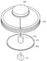
도 5는 본 발명의 제1 실시 예에 따른 무선전력 송신장치(400)의 구조도이다.5 is a structural diagram of a wireless
본 발명의 일 실시 예에 따른 무선전력 송신장치(400)는 수신 측이 무선전력 송신장치(400)의 위가 아닌 측면에 위치한 경우에 보다 효과적인 전력 전송을 수행할 수 있다.The wireless
도 5를 참고하면, 무선전력 송신장치(400)는 전원 연결부(401), 제1 기판(403), 송신 유도 코일(405), 송신 공진 코일(407), 제2 기판(409), 차폐부(411), 송신 회로부(413), 받침부(415), 지지대(417)를 포함한다.5, the wireless
전원 공급부(10)는 무선전력 송신장치(400)에 직류 전력을 공급할 수 있다.The
전원 공급부(10)는 무선전력 송신장치(400)에 포함될 수도 있다.The
전원 연결부(401)는 전원 공급부(10)에서 공급된 전원을 송신 유도 코일(405)로 전달할 수 있다. 일 실시 예에서 전원 연결부(401)는 후술할 송신 공진 코일(407)의 측면에 인접하게 배치될 수 있다.The
일 실시 예에서 전원 연결부(401)는 제1 기판(403) 상에 배치될 수 있다. 이에 대해서는 도 7에서 상세히 설명한다.In one embodiment, the
제1 기판(403)은 인쇄회로기판(PCB: Printed Circuit Board)일 수 있다.The
송신 유도 코일(405)은 제1 기판(403) 상에 배치될 수 있다. 일 실시 예에서 제1 기판(403)이 원형의 형태를 갖는 경우, 송신 유도 코일(405)은 제1 기판(403)의 외곽선을 따라 배치될 수 있다. 여기서, 제1 기판(403)이 원형의 형태를 갖는 것은 예시에 불과하고, 제1 기판(403)은 사각형 등 다각형의 형태를 포함할 수 있다. 제1 기판(403)의 형태에 따라 제1 기판(403) 상에 배치되는 송신 유도 코일(405)의 형태도 달라질 수 있다.The
송신 유도 코일(405)은 하나의 도선이 복수 번 권선되고, 제1 기판(403) 상에 일정한 패턴을 형성하여 배치될 수 있다.The
송신 유도 코일(405)은 전원 공급부(10)로부터 받은 전력을 전자기 유도에 의해 물리적으로 이격되어 있는 송신 공진 코일(407)에 전달할 수 있다.The
송신 유도 코일(405)은 제1 기판(403) 상의 급전선을 통해 송신 공진 코일(407)의 캐패시터(408)와 연결될 수 있다.The
송신 공진 코일(407)은 송신 유도 코일(405)로부터 전자기 유도에 의해 전력을 전달받을 수 있다.The
송신 공진 코일(407)은 송신 유도 코일(405)에 수직으로 배치될 수 있다. 송신 공진 코일(407)과 송신 유도 코일(405)은 소정의 수직거리만큼 이격되어 배치될 수 있다.The
송신 유도 코일(405) 및 송신 공진 코일(407)에 대한 내용은 도 1에서 설명한 송신 유도 코일(210) 및 송신 공진 코일(220)의 내용을 모두 포함할 수 있다.The contents of the
도 5에 도시된 바와 같이, 일 실시 예에서 송신 공진 코일(407)은 하나의 도선이 복수 번 권선되어 적층된 구조를 가질 수 있다. 송신 공진 코일(407)은 소정의 지름을 갖는 원통형, 스파이럴형 등 다양한 형태를 포함할 수 있다.As shown in FIG. 5, in one embodiment, the
송신 공진 코일(407)은 자기 공진을 이용하여 무선전력 수신장치(미도시)의 수신 공진 코일(미도시)에 전력을 전송할 수 있다.The
받침부(415) 위에는 차폐부(411), 제2 기판(409), 송신 회로부(413)가 아래에서부터 위로 차례대로 배치될 수 있다.The shielding
송신 회로부(413)는 전원 공급부(10)로부터 공급된 전력을 통해 자기 공진을 위한 주파수를 가지는 전력으로 변환할 수 있다.The
송신 회로부(413)는 직류 직류 변환기, 발진기, 변환부 등을 포함할 수 있다.The
직류 직류 변환기는 전원 공급부(10)로부터 받은 전원을 원하는 출력 전원으로 변환할 수 있다.DC direct current converter can convert the power received from the
발진기는 자기 공진을 위한 주파수를 갖는 교류전력을 생성할 수 있다.The oscillator may generate alternating current power having a frequency for self resonance.
변환부는 직류 직류 변환기로부터 수신한 직류전원과 발진기로부터 수신한 교류전력을 이용해 증폭된 교류전력을 출력한다. 출력된 교류전력은 송신 유도 코일(405)에 전달된다.The converting unit outputs the AC power amplified by the DC power received from the DC-DC converter and the AC power received from the oscillator. The output AC power is transmitted to the
송신 회로부(413)는 제2 기판(409) 상에 배치될 수 있다. 송신 회로부(413)는 칩(Chip)형태일 수 있고, 복수의 칩으로 구성될 수 있다. 여기서, 제2 기판(409)은 인쇄회로기판(PCB: Printed Circuit Board)일 수 있다. 일 실시 예에서 제2 기판(409)은 윗면이 개방된 원통형의 형상을 가질 수 있으나, 이에 한정될 필요는 없다.The transmitting
제2 기판(409)이 원통형인 경우, 제2 기판(409)의 밑면 위에 송신 회로부(413)가 배치될 수 있다.When the
이하에서는, 제2 기판(409)이 윗면이 개방된 원통형의 형상을 가지는 경우를 예로 들어 설명한다.Hereinafter, the case where the
제2 기판(409)의 밑면 지름과 송신 공진 코일(407)이 형성하는 지름은 소정의 비율을 가질 수 있다. 일 실시 예에서 제2 기판(409)의 밑면 지름과 송신 공진 코일(407)이 형성하는 지름은 3:8의 비율을 가질 수 있다. 여기서, 송신 공진 코일(407)이 형성하는 지름은 송신 공진 코일(407)이 동축 나선형의 구조를 갖는 경우, 송신 공진 코일(407)의 중심을 관통한 가장 외곽에 배치된 도선의 일점과 타점 사이의 거리를 의미할 수 있다.The bottom surface diameter of the
또한, 제2 기판(409)의 밑면과 송신 공진 코일(407)은 소정의 수직거리를 가지고, 배치될 수 있다. 일 실시 예에서 상기 수직거리는 바람직하게는 15mm 이상일 수 있다.Further, the bottom surface of the
제2 기판(409)의 밑면 지름과 송신 공진 코일(407)이 형성하는 지름의 비율, 제2 기판(409)의 밑면과 송신 공진 코일(407)과의 수직거리는 품질 인자(Quality factor) 및 전력전송 효율과 연관된다. 품질 인자(Quality factor)는 무선전력 전송 시스템의 단위시간 당 에너지 손실의 역수로, Q값이 클수록 무선전력 전송 시스템의 성능이 좋은 것으로 평가된다. 전력전송 효율은 무선전력 송신장치(400)에서 전송하는 전력과 무선전력 수신장치가 수신하는 전력의 비율을 의미할 수 있다.The vertical distance between the bottom surface of the
제2 기판(409)의 밑면 지름과 송신 공진 코일(407)이 형성하는 지름의 비율이 3:8인 상태에서 제2 기판(409)의 밑면과 송신 공진 코일(407)과의 수직거리가 변함에 따라 Q값 및 전력전송 효율은 달라질 수 있다. 이에 대한 상세한 설명은 후술한다.The vertical distance between the bottom surface of the
받침부(415)는 차폐부(411), 제2 기판(409), 송신 회로부(413)를 수용할 수 있다. 일 실시 예에서 받침부(415)는 밑면이 소정의 지름을 갖는 원통형의 형상을 가질 수 있다.The receiving
적어도 하나 이상의 지지대(417)는 제1 기판(403)과 받침부(415)를 수직으로 연결할 수 있다.At least one
차폐부(411)는 송신 공진 코일(407)에서 형성된 자속의 방향을 변경시킬 수 있다. 즉, 차폐부(411)는 송신 공진 코일(407)에서 형성된 자속의 방향을 무선전력 수신장치가 위치한 곳으로 변경시킬 수 있다. 이로 인해, 송신 공진 코일(407)에서 형성된 자속은 보다 집중적으로 무선전력 수신장치 측에 전달될 수 있다. 바람직하게, 무선전력 수신장치가 무선전력 송신장치(400)의 측면에 배치된 경우, 차폐부(411)는 송신 공진 코일(407)에서 형성된 자속의 방향을 변경시켜 무선전력 수신장치 측으로 자속을 전달할 수 있다.
차폐부(411)는 제2 기판(409)을 둘러싸는 형태를 가질 수 있다. 즉, 차폐부(411)는 제2 기판(409)과 동일한 형상을 가질 수 있다.The shielding
차폐부(411)는 송신 공진 코일(407)에서 형성된 자속의 방향을 변경시켜 송신 회로부(413)의 오작동을 방지할 수 있다. 송신 공진 코일(407)에서 형성된 자속은 송신 회로부(413)에 전송되어, 송신 회로부(413)에 전달되어 영향을 끼칠 수 있기 때문에, 차폐부(411)는 이를 방지하여 송신 회로부(413)를 보호할 수 있다.
The shielding
다음으로, 본 발명의 일 실시 예에 따른 무선전력 송신장치(400)의 구성요소 간 배치관계를 살펴보기로 한다.
Next, the arrangement relationship among the components of the wireless
도 6은 본 발명의 일 실시 예에 따른 무선전력 송신장치(400)의 정면도이다.6 is a front view of a wireless
도 6을 참고하면, 무선전력 송신장치(400)는 전원 연결부(401), 제1 기판(403), 송신 유도 코일(405), 송신 공진 코일(407), 제2 기판(409), 차폐부(411), 송신 회로부(413), 지지대(417)를 포함한다.6, the wireless
무선전력 송신장치(400)의 각 구성요소의 기능은 도 5에서 설명한 것과 같으므로 자세한 설명은 생략하고, 이하에서는 각 구성요소의 배치를 중심으로 설명한다.Since the functions of the respective components of the wireless
무선전력 송신장치(400)의 가장 아랫단에는 제1 기판(403)이 배치된다.The
제1 기판(403) 상에는 송신 유도 코일(405)이 일정한 패턴을 가지고 형성되어 있다.On the
송신 공진 코일(407)은 송신 유도 코일(405)의 수직방향으로 소정의 거리만큼 이격되어 배치된다.The
송신 공진 코일(407)은 하나의 도선이 복수 번 권선되어, 적층된 구조를 갖는다.The
송신 공진 코일(407)이 형성하는 높이는 10mm일 수 있으나, 이는 예시에 불과하다.The height formed by the
송신 공진 코일(407)의 일단에는 전원 연결부(401)가 도시되어 있다. 전원 연결부(401)의 높이는 5m 일 수 있으나, 이는 예시에 불과하다.A
제2 기판(409)은 송신 공진 코일(407)과 일정한 수직거리만큼 이격된 곳에 배치될 수 있다. 제2 기판(409)과 송신 공진 코일(407)과의 수직거리는 15mm일 수 있다. 여기서, 15mm는 예시에 불과하다.The
제2 기판(409) 상에는 복수의 칩을 포함하는 송신 회로부(413)가 배치될 수 있다.On the
제2 기판(409)은 윗면이 개방된 원통형의 형태일 수 있으나, 이에 한정될 필요는 없고, 원형의 형태를 가질 수 있다.The
차폐부(411)는 제2 기판(409)을 둘러싸고 있고, 제2 기판(409)과 같은 형상을 가지고 있다.The shielding
받침부(415)는 차폐부(411) 아랫단에 인접하여 배치된다.The receiving
받침부(415)는 제1 기판(403)과 복수의 지지대(417)를 통해 연결될 수 있다.The
복수의 지지대(417)는 제1 기판(403)과 받침부(415)를 연결하고, 지지하는 역할을 한다.The plurality of
제2 기판(409)의 밑면이 원형인 경우, 제2 기판(409)의 밑면 지름은 30mm 이고, 송신 공진 코일(407)이 형성하는 지름은 80mm 일 수 있으나, 이는 예시에 불과하고, 제2 기판(409)의 밑면 지름과 송신 공진 코일(407)이 형성하는 지름은 그 비율이 3:8이 되는 어떠한 수치든지 가능할 수 있다.
When the bottom surface of the
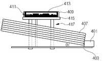
도 7은 본 발명의 제2 실시 예에 따른 무선전력 송신장치(400)의 구조도이다.7 is a structural diagram of a wireless
도 7을 참고하면, 본 발명의 제2 실시 예에 따른 무선전력 송신장치(400)는 전원 연결부(401), 제1 기판(403), 송신 유도 코일(405), 송신 공진 코일(407), 제2 기판(409)을 포함한다. 물론, 무선전력 송신장치(400)는 이외에도 도 5에서 설명한 구성요소들을 더 포함할 수 있다.Referring to FIG. 7, a wireless
본 발명의 제2 실시 예에 따른 무선전력 송신장치(400)는 도 5와 비교하여 전원 연결부(401)의 위치가 변경된 구조를 갖는다.The wireless
구체적으로, 도 5의 무선전력 송신장치(400)의 전원 연결부(401)는 송신 공진 코일(407)의 제1 기판(403)의 측면에 배치되나, 본 발명의 제2 실시 예에 따른 무선전력 송신장치(400)의 전원 연결부(401)는 제1 기판(403)의 윗면에 배치된다.5 is disposed on the side of the
전원 연결부(401)가 제1 기판(403)의 측면에 배치되는 경우, 송신 공진 코일(407)에서 형성되어 수신 측으로 전달되는 일부 자속은 전원 연결부(401)에 의해 흡수 또는 차단되어 전력전송 효율에 영향을 끼칠 수 있다.When the
전원 연결부(401)가 제1 기판(403)의 윗면에 배치되면, 송신 공진 코일(407)에서 형성되어 수신 측으로 전달되는 자속은 전원 연결부(401)에 의해 흡수 또는 차단되지 않을 수 있다. 즉, 도 7과 같은 전원 연결부(401)의 배치로 인해, 전력 전송 효율을 증가시킬 수 있는 이점이 있다.When the
구체적으로, 도 7의 무선전력 송신장치(400)의 전원 연결부(401) 배치는 도 5의 무선전력 송신장치(400)의 전원 연결부(401) 배치에 비해 전력전송 효율이 3%정도 증가하고, 품질 지수는 120만큼 높아지는 효과를 갖는다.
The
도 8은 본 발명의 제1 실시 예에 따른 무선전력 송신장치(400)의 송신 공진 코일(407)과 제2 기판(409)과의 수직거리에 따른 Q 값 및 전력전송 효율의 변화를 설명하기 위한 도면이다.8 is a graph illustrating the change of the Q value and the power transmission efficiency according to the vertical distance between the
제2 기판(409)의 밑면 지름은 30mm 이고, 송신 공진 코일(407)이 형성하는 지름은 80mm 임을 가정한다.It is assumed that the bottom surface diameter of the
도 8을 참고하면, 송신 공진 코일(407)과 제2 기판(409)과의 수직거리가 0mm 인 경우, Q값은 560이고, 수직거리가 증가함에 따라 Q값이 증가한다.Referring to FIG. 8, when the vertical distance between the
그러다가, 송신 공진 코일(407)과 제2 기판(409)과의 수직거리가 15mm 인 경우, Q값이 최대인 700이 되고, 그 후, 수직거리가 증가함에 따라 Q값은 미세하게 증가한다.If the vertical distance between the
또한, 송신 공진 코일(407)과 제2 기판(409)과의 수직거리가 0mm인 경우, 30mm 외곽에 위치한 수신 측에 전달하는 전력전송 효율이 18%이라고 하면, 수직거리가 증가함에 따라 전력전송 효율이 증가한다.When the vertical distance between the
그러다가, 송신 공진 코일(407)과 제2 기판(409)과의 수직거리가 15mm 인 경우, 30mm 외곽에 위치한 수신 측에 전달하는 전력전송 효율은 22%가 되고, 그 후, 수직거리가 증가함에 따라 전력전송 효율은 미세하게 증가한다.When the vertical distance between the
이와 같이 송신 공진 코일(407)과 제2 기판(409)과의 수직거리가 증가함에 따라 일정 범위 이내에서는 Q 값 및 전력전송 효율이 증가함을 확인할 수 있다.
As the vertical distance between the transmitting
다음으로 도 9 내지 도 13을 참조하여, 본 발명의 제3 실시 예에 따른 무선전력 송신장치(400) 및 전력 전송 효율에 대해 설명한다.Next, with reference to FIG. 9 to FIG. 13, a wireless
도 9는 본 발명의 제3 실시 예에 따른 무선전력 송신장치(400)의 구조도이고, 도 10은 본 발명의 제1 실시 예에 따른 무선전력 송신장치(400)의 전력 전송 과정을 설명하기 위한 도면이고, 도 11 및 도 12는 본 발명의 제3 실시 예에 따른 무선전력 송신장치(400)의 전력 전송 과정을 설명하기 위한 도면이고, 도 13은 본 발명의 제3 실시 예에 따른 무선전력 송신장치(400)를 사용한 경우, 전력 전송 효율을 설명하기 위한 도면이다.FIG. 9 is a structural diagram of a wireless
먼저, 도 9를 참조하면, 무선전력 송신장치(400)는 전원 연결부(401), 제1 기판(403), 송신 유도 코일(405), 송신 공진 코일(407), 제2 기판(409), 차폐부(411), 송신 회로부(413), 받침부(415), 지지대(417)를 포함할 수 있다. 상기 각 구성요소들은 도 5에서 설명한 내용과 본질적으로 동일하다.9, a wireless
송신 공진 코일(407)은 수평면의 수평선을 기준으로 일정한 각도로 기울어져 있을 수 있다. 보다, 구체적으로 송신 공진 코일(407)은 무선전력 송신장치(400)가 놓여있는 면의 수평선과 임의의 각도로 기울어져 배치될 수 있다. 바람직하게 송신 공진 코일(407)과 수평선이 이루는 각도는 0도 내지 30사이 일 수 있다.The
송신 공진 코일(407)은 일 측이 사용하고자 하는 충전 영역으로 기 설정된 각도를 갖도록 기울어져 배치될 수 있다.송신 공진 코일(407)이 수평선을 기준으로 기 설정된 각도를 이루는 것은 충전 영역에 위치한 무선전력 수신장치(300)에 높은 효율로 전력 전송을 가능케 하기 위함이다.The
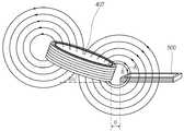
도 10은 송신 공진 코일(407)과 수평선이 이루는 각도가 0도인 경우, 송신 공진 코일(407)에서 발생하는 자기장의 자기력선을 보여주고 있고, 도 11은 송신 공진 코일(407)과 수평선이 이루는 각도가 10도인 경우, 송신 공진 코일(407)에서 발생하는 자기장의 자기력선을 보여주고 있고, 도 12는 송신 공진 코일(407)과 수평선이 이루는 각도가 20도인 경우, 송신 공진 코일(407)에서 발생하는 자기장의 자기력선을 보여주고 있다.10 shows a magnetic force line of a magnetic field generated by the
도 10 내지 도 12에서, 전자기기(600)는 도 1 내지 도 4에서 설명한 무선전력 수신장치(300)를 포함할 수 있고, 송신 공진 코일(407)로부터 자기장을 이용해 전력을 수신할 수 있다. 전자기기(600)는 휴대폰, 노트북, 마우스 일 수 있으나, 이에 한정될 필요는 없고, 무선전력 송신장치(400)로부터 전력을 수신할 수 있는 모든 기기를 포함할 수 있다.10 to 12, the
또한, 도 10 내지 도 12에서, 각 전력 전송 효율의 비교를 위해 송신 공진 코일(407)과 전자기기(600) 간 거리(d)는 일정하고, 전자기기(600)는 송신 공진 코일(407)의 우 측면에 위치하는 것으로 가정한다.10 to 12, the distance d between the
또한, 도 10 내지 도 12에서, 송신 공진 코일(407)에서 발생하는 자기력선이 전자기기(600)를 관통하면, 전자기기(600)에 전력이 전송되는 것으로 볼 수 있고, 송신 공진 코일(407)에서 발생하는 자기장의 자기력선이 전자기기(600)를 관통하지 않으면, 전자기기(600)에 전력이 전송되지 않는 것으로 볼 수 있다.10 to 12, when a magnetic force line generated by the
도 10을 참조하면, 송신 공진 코일(407)과 수평선이 이루는 각도가 0도이다. 이 때, 송신 공진 코일(407)에서 발생하는 복수의 자기력선 중 일부는 전자기기(600)를 관통하지만, 일부는 전자기기(600)를 관통하지 않을 수 있다. 즉, 도 10에 도시된 것처럼 자기력선(A) 및 자기력선(B)는 전자기기(600)를 관통하지 않는다.Referring to FIG. 10, the angle between the
반면, 도 11을 참조하면, 송신 공진 코일(407)과 전자기기(600)가 이루는 각도가 10도이다. 이 때, 도 10에서 전자기기(600)를 관통하지 않았던 자기력선(A)은 전자기기(600)를 관통한다. 이는, 송신 공진 코일(407)이 전자기기(600) 측으로 기울어짐에 따라 송신 공진 코일(407)에서 발생하는 자기력선들 중 전자기기(600) 측을 향하는 자기력선이 많아지기 때문이다.11, the angle between the
또한, 도 12를 참조하면, 송신 공진 코일(407)과 전자기기(600)가 이루는 각도가 20도이다. 도 10 및 도 11에서 전자기기(600)를 관통하지 않았던 자기력선(B)은 전자기기(600)를 관통한다. 이는, 도 11에 비해 송신 공진 코일(407)이 전자기기 측으로 더 기울어짐에 따라 송신 공진 코일(407)에서 발생하는 자기력선 중 전자기기(600) 측을 향하는 자기력선이 더 많아지기 때문이다.Referring to FIG. 12, the angle formed between the
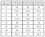
도 13을 참조하면, 본 발명의 제3 실시 예에 따라 송신 공진 코일(407)의 각도를 0도에서 21도 까지 변경시킴에 따른 전력 전송 효율을 정리한 표이다. 전자기기(600)는 송신 공진 코일(407)의 우 측면에 위치하고, 송신 공진 코일(407)은 전자기기(600) 측으로 기울어지면서 각도가 변경된다. 전력 전송 효율은 무선전력 송신장치(400)에서 송신한 전력량 중 전자기기(600)에 장착된 무선전력 수신장치(300)가 수신한 전력량의 비율일 수 있다. 또한, 전력 전송 효율이 증가하면, 송신 공진 코일(407)과 전자기기(600)에 포함된 수신 공진 코일(310)간 결합계수(Coupling Coefficient)가 증가하는 것을 의미할 수 있다.13 is a table summarizing the power transmission efficiency according to the third embodiment of the present invention when the angle of the
우 측면에서의 전력 전송 효율은 도 10 내지 도 12에서 도시한 바와 같이, 무선전력 송신장치(400)의 우측에 전자기기(600)가 위치했을 때의 전력 전송 효율이고, 전(후)면에서의 전력 전송 효율은 무선전력 송신장치(400)의 전면 또는 후면에 전자기기(600)가 위치했을 때의 전력 전송 효율이고, 좌 측면에서의 전력 전송 효율은 무선전력 송신장치(400)의 좌측에 전자기기(600)가 위치했을 때의 전력 전송 효율이다.As shown in FIGS. 10 to 12, the power transmission efficiency on the right side is the power transmission efficiency when the
송신 공진 코일(407)의 우 측면, 전(후) 면, 좌 측면에 위치한 전자기기(600)와 송신 공진 코일(407)간의 거리는 같음을 가정한다.It is assumed that the distances between the
도 13을 참조하면, 송신 공진 코일(407)이 수평선과 이루는 각도가 0도인 경우, 송신 공진 코일(407)의 우 측면, 전(후) 면, 좌 측면에 위치한 전자기기(600)와의 전력 전송 효율은 25%이다.Referring to FIG. 13, when the
또한, 전자기기(600)가 송신 공진 코일(407)의 우 측면, 전(후)면, 좌 측면에 위치한 경우 모두, 송신 공진 코일(407)이 수평선과 이루는 각도가 커질수록 전력 전송 효율이 증가함을 확인할 수 있다.In the case where the
또한, 송신 공진 코일(407)의 우 측면에 전자기기(600)가 위치한 경우, 송신 공진 코일(407)이 수평선과 이루는 각도가 커질수록 전(후)면 및 좌 측면에 위치한 경우에 비해 전력 전송 효율이 증가함을 확인할 수 있다. 다만, 이 경우, 송신 공진 코일(407)이 수평선과 이루는 각도는 무선전력 송신장치(400)의 전체적인 사이즈를 고려해 볼 때, 0도에서 30도 사이가 바람직하다.
When the
또한, 이상에서는 본 발명의 바람직한 실시 예에 대하여 도시하고 설명하였지만, 본 발명은 상술한 특정의 실시 예에 한정되지 아니하며, 청구범위에서 청구하는 본 발명의 요지를 벗어남이 없이 당해 발명이 속하는 기술분야에서 통상의 지식을 가진 자에 의해 다양한 변형 실시가 가능한 것은 물론이고, 이러한 변형 실시들은 본 발명의 기술적 사상이나 전망으로부터 개별적으로 이해 되어서는 안될 것이다.While the present invention has been particularly shown and described with reference to exemplary embodiments thereof, it is to be understood that the invention is not limited to the disclosed exemplary embodiments, but, on the contrary, It should be understood that various modifications may be made by those skilled in the art without departing from the spirit and scope of the present invention.
100: 전력 소스
200: 무선전력 송신장치
210: 송신 유도 코일
220: 송신 공진 코일
300: 무선전력 수신장치
310: 수신 공진 코일
320: 수신 유도 코일
330: 정류회로
340: 부하
400: 무선전력 송신장치
401: 전원 연결부
403: 제1 기판
405: 송신 유도 코일
407: 송신 공진 코일
408: 커패시터
409: 제2 기판
411: 차폐부
413: 송신 회로부
415: 받침부
417: 지지대
600: 전자기기100: Power source
200: Wireless power transmitting device
210: transmission induction coil
220: transmission resonance coil
300: Wireless power receiving device
310: Receive resonant coil
320: reception induction coil
330: rectifier circuit
340: Load
400: wireless power transmission device
401: Power connection
403: first substrate
405: Transmission induction coil
407: Transmission resonance coil
408: Capacitor
409: second substrate
411:
413:
415:
417: Support
600: Electronic device
Claims (16)
Translated fromKorean전원 공급부;
상기 전원 공급부와 연결된 송신 유도 코일;
상기 송신 유도 코일과 유도 결합되어 전달받은 전력을 공진을 이용하여 상기 무선전력 수신장치에 전송하는 송신 공진 코일;
상기 송신 공진 코일에서 형성되는 자속의 방향을 변경시키는 차폐부;
상기 전원 공급부로부터 공급된 전력을 공진을 위한 주파수를 가지는 전력으로 변환하는 송신 회로부;
상기 송신 유도 코일을 배치하기 위한 제1 기판; 및
상기 제1 기판과 수직으로 이격되고, 상기 송신 회로부를 배치하기 위한 제2 기판을 포함하고,
상기 송신 공진 코일은 수평면과 일정한 각도를 갖도록 기울어져 배치되며,
상기 송신 회로부는 상기 송신 공진 코일과 수직으로 이격하여 배치된 것을 특징으로 하는 무선전력 송신장치.A wireless power transmission apparatus for wirelessly transmitting power to a wireless power receiving apparatus mounted on an electronic device,
Power supply;
A transmission induction coil connected to the power supply;
A transmission resonance coil for transmitting the power received inductively coupled to the transmission induction coil to the wireless power reception apparatus using resonance;
A shield for changing a direction of a magnetic flux formed in the transmission resonance coil;
A transmission circuit for converting power supplied from the power supply unit into power having a frequency for resonance;
A first substrate for arranging the transmission induction coil; And
And a second substrate spaced vertically from the first substrate for arranging the transmission circuit portion,
Wherein the transmission resonance coil is tilted so as to have a certain angle with the horizontal plane,
Wherein the transmission circuit section is disposed so as to be vertically spaced from the transmission resonance coil.
상기 송신 공진 코일은 일 측이 사용하고자 하는 충전 영역으로 기설정된 각도를 갖도록 기울어져 배치되는 것을 특징으로 하는 무선전력 송신장치.The method according to claim 1,
Wherein the transmission resonance coil is disposed such that one side thereof is tilted so as to have a predetermined angle to a charging region to be used.
상기 일정한 각도는,
0.1도 내지 30도의 범위를 갖는 것을 특징으로 하는 무선전력 송신장치.The method according to claim 1,
The constant angle
And has a range of 0.1 to 30 degrees.
상기 송신 회로부와 상기 송신 공진 코일의 수직거리는 0.1mm 내지 25mm 범위를 갖는 무선전력 송신장치.The method according to claim 1,
Wherein the vertical distance between the transmission circuit section and the transmission resonance coil has a range of 0.1 mm to 25 mm.
상기 송신 공진 코일은 동축 나선형의 구조이고, 상기 제2 기판은 윗면이 개방된 원통형의 구조인 무선전력 송신장치.The method according to claim 1,
Wherein the transmission resonant coil is a coaxial spiral structure, and the second substrate is a cylindrical structure with an open top surface.
상기 제2 기판의 밑면 지름과 상기 송신 공진 코일이 형성하는 지름의 비율은 3:8인 무선전력 송신장치.8. The method of claim 7,
Wherein the ratio of the bottom surface diameter of the second substrate to the diameter of the transmission resonance coil is 3: 8.
상기 전원 공급부로부터 전원을 공급받아 상기 송신 회로부로 전달하는 전원 연결부를 더 포함하는 무선전력 송신장치.The method according to claim 1,
And a power connection unit that receives power from the power supply unit and transmits the power to the transmission circuit unit.
상기 전원 연결부는,
상기 제1 기판 위에 배치되는 무선전력 송신장치.10. The method of claim 9,
The power connection unit includes:
And the second substrate is disposed on the first substrate.
상기 제1 기판 및 제2 기판은 인쇄회로기판인 무선전력 송신장치.The method according to claim 1,
Wherein the first substrate and the second substrate are printed circuit boards.
상기 제1 기판은 원형의 형태이고,
상기 송신 유도 코일은 상기 제1 기판의 외곽선을 따라 배치되는 무선전력 송신장치.The method according to claim 1,
The first substrate has a circular shape,
Wherein the transmission induction coil is disposed along an outline of the first substrate.
상기 제2 기판 및 상기 송신 회로부를 수용하는 받침부를 더 포함하고,
상기 받침부는 적어도 하나 이상의 지지대에 의해 상기 제1 기판과 연결되는 무선전력 송신장치.The method according to claim 1,
Further comprising a receiving portion for receiving the second substrate and the transmitting circuit portion,
Wherein the support portion is connected to the first substrate by at least one support.
상기 송신 유도 코일은 상기 제1 기판 상의 급전선을 통해 상기 송신 공진 코일의 캐패시터와 연결된 무선전력 송신장치.
The method according to claim 1,
Wherein the transmission induction coil is connected to a capacitor of the transmission resonance coil via a feed line on the first substrate.
Priority Applications (2)
| Application Number | Priority Date | Filing Date | Title |
|---|---|---|---|
| KR1020120060781AKR101438888B1 (en) | 2012-06-07 | 2012-06-07 | Apparatus for transmitting wireless power and system for transmitting wireless power |
| US13/835,817US9634731B2 (en) | 2012-03-19 | 2013-03-15 | Wireless power transmitter |
Applications Claiming Priority (1)
| Application Number | Priority Date | Filing Date | Title |
|---|---|---|---|
| KR1020120060781AKR101438888B1 (en) | 2012-06-07 | 2012-06-07 | Apparatus for transmitting wireless power and system for transmitting wireless power |
Publications (2)
| Publication Number | Publication Date |
|---|---|
| KR20130137312A KR20130137312A (en) | 2013-12-17 |
| KR101438888B1true KR101438888B1 (en) | 2014-09-05 |
Family
ID=49983563
Family Applications (1)
| Application Number | Title | Priority Date | Filing Date |
|---|---|---|---|
| KR1020120060781AExpired - Fee RelatedKR101438888B1 (en) | 2012-03-19 | 2012-06-07 | Apparatus for transmitting wireless power and system for transmitting wireless power |
Country Status (1)
| Country | Link |
|---|---|
| KR (1) | KR101438888B1 (en) |
Citations (4)
| Publication number | Priority date | Publication date | Assignee | Title |
|---|---|---|---|---|
| KR20110049659A (en)* | 2009-11-04 | 2011-05-12 | 한국전기연구원 | Space Adaptive Wireless Power Transmission System and Method Using Attenuation Wave Resonance |
| KR20110060795A (en)* | 2009-11-30 | 2011-06-08 | 삼성전자주식회사 | Wireless Power Transceivers and Wireless Power Systems |
| JP2011125184A (en) | 2009-12-14 | 2011-06-23 | Toyota Motor Corp | Contactless power supply facility, contactless power receiving device, and contactless power supply system |
| KR20120017526A (en)* | 2010-08-19 | 2012-02-29 | 엘지전자 주식회사 | Wireless power transmission method and apparatus |
- 2012
- 2012-06-07KRKR1020120060781Apatent/KR101438888B1/ennot_activeExpired - Fee Related
Patent Citations (4)
| Publication number | Priority date | Publication date | Assignee | Title |
|---|---|---|---|---|
| KR20110049659A (en)* | 2009-11-04 | 2011-05-12 | 한국전기연구원 | Space Adaptive Wireless Power Transmission System and Method Using Attenuation Wave Resonance |
| KR20110060795A (en)* | 2009-11-30 | 2011-06-08 | 삼성전자주식회사 | Wireless Power Transceivers and Wireless Power Systems |
| JP2011125184A (en) | 2009-12-14 | 2011-06-23 | Toyota Motor Corp | Contactless power supply facility, contactless power receiving device, and contactless power supply system |
| KR20120017526A (en)* | 2010-08-19 | 2012-02-29 | 엘지전자 주식회사 | Wireless power transmission method and apparatus |
Also Published As
| Publication number | Publication date |
|---|---|
| KR20130137312A (en) | 2013-12-17 |
Similar Documents
| Publication | Publication Date | Title |
|---|---|---|
| EP2787517B1 (en) | Wireless power repeater | |
| JP5934934B2 (en) | Wireless power transmission system | |
| JP2015534422A (en) | Non-contact power transmission system | |
| US9923388B2 (en) | Wireless power transmitter | |
| JP6084994B2 (en) | Wireless power receiving apparatus, terminal, and wireless power transmitting apparatus | |
| JP2015505664A (en) | Wireless power transfer device using separately tunable resonators | |
| US9570935B2 (en) | Magnetic coupling unit and magnetic coupling system | |
| CN102570630A (en) | Wireless power transmission apparatus and system for wireless power transmission thereof | |
| WO2013145788A1 (en) | Power transmitting device, electronic equipment and wireless power transmission system | |
| KR20150067520A (en) | Apparatus for transmitting wireless power | |
| KR101382920B1 (en) | Apparatus for transmitting wireless power | |
| JP2013542700A (en) | RESONANT POWER TRANSMITTING SYSTEM POWER CONVERTER AND RESONANT POWER TRANSMITTING DEVICE | |
| KR20140076993A (en) | Wireless power device | |
| KR20150021285A (en) | Wireless power receiving device | |
| US10879736B2 (en) | Wireless power transfer systems and methods using non-resonant power receiver | |
| KR101976613B1 (en) | Wireless power receiver | |
| KR101372088B1 (en) | Coil and apparatus for transmitting wireless power | |
| CN107346918A (en) | A wireless power transmission device | |
| KR101327024B1 (en) | Apparatus for transmitting wireless power and system for transmitting wireless power | |
| KR101438888B1 (en) | Apparatus for transmitting wireless power and system for transmitting wireless power | |
| US9634731B2 (en) | Wireless power transmitter | |
| KR101349448B1 (en) | Apparatus for delivering wireless power | |
| KR101305790B1 (en) | Apparatus for transmitting wireless power and apparatus for receiving wireless power | |
| KR101294581B1 (en) | Apparatus for delivering wireless power and terminal | |
| KR20120116801A (en) | A wireless power transmission circuit, a wireless power transmitter and receiver |
Legal Events
| Date | Code | Title | Description |
|---|---|---|---|
| A201 | Request for examination | ||
| PA0109 | Patent application | St.27 status event code:A-0-1-A10-A12-nap-PA0109 | |
| PA0201 | Request for examination | St.27 status event code:A-1-2-D10-D11-exm-PA0201 | |
| PG1501 | Laying open of application | St.27 status event code:A-1-1-Q10-Q12-nap-PG1501 | |
| D13-X000 | Search requested | St.27 status event code:A-1-2-D10-D13-srh-X000 | |
| D14-X000 | Search report completed | St.27 status event code:A-1-2-D10-D14-srh-X000 | |
| E902 | Notification of reason for refusal | ||
| PE0902 | Notice of grounds for rejection | St.27 status event code:A-1-2-D10-D21-exm-PE0902 | |
| E13-X000 | Pre-grant limitation requested | St.27 status event code:A-2-3-E10-E13-lim-X000 | |
| P11-X000 | Amendment of application requested | St.27 status event code:A-2-2-P10-P11-nap-X000 | |
| P13-X000 | Application amended | St.27 status event code:A-2-2-P10-P13-nap-X000 | |
| E701 | Decision to grant or registration of patent right | ||
| PE0701 | Decision of registration | St.27 status event code:A-1-2-D10-D22-exm-PE0701 | |
| GRNT | Written decision to grant | ||
| PR0701 | Registration of establishment | St.27 status event code:A-2-4-F10-F11-exm-PR0701 | |
| PR1002 | Payment of registration fee | St.27 status event code:A-2-2-U10-U11-oth-PR1002 Fee payment year number:1 | |
| PG1601 | Publication of registration | St.27 status event code:A-4-4-Q10-Q13-nap-PG1601 | |
| PN2301 | Change of applicant | St.27 status event code:A-5-5-R10-R13-asn-PN2301 St.27 status event code:A-5-5-R10-R11-asn-PN2301 | |
| P22-X000 | Classification modified | St.27 status event code:A-4-4-P10-P22-nap-X000 | |
| R18-X000 | Changes to party contact information recorded | St.27 status event code:A-5-5-R10-R18-oth-X000 | |
| FPAY | Annual fee payment | Payment date:20170804 Year of fee payment:4 | |
| PR1001 | Payment of annual fee | St.27 status event code:A-4-4-U10-U11-oth-PR1001 Fee payment year number:4 | |
| R18-X000 | Changes to party contact information recorded | St.27 status event code:A-5-5-R10-R18-oth-X000 | |
| FPAY | Annual fee payment | Payment date:20180809 Year of fee payment:5 | |
| PR1001 | Payment of annual fee | St.27 status event code:A-4-4-U10-U11-oth-PR1001 Fee payment year number:5 | |
| P22-X000 | Classification modified | St.27 status event code:A-4-4-P10-P22-nap-X000 | |
| P22-X000 | Classification modified | St.27 status event code:A-4-4-P10-P22-nap-X000 | |
| PR1001 | Payment of annual fee | St.27 status event code:A-4-4-U10-U11-oth-PR1001 Fee payment year number:6 | |
| R18-X000 | Changes to party contact information recorded | St.27 status event code:A-5-5-R10-R18-oth-X000 | |
| PC1903 | Unpaid annual fee | St.27 status event code:A-4-4-U10-U13-oth-PC1903 Not in force date:20200902 Payment event data comment text:Termination Category : DEFAULT_OF_REGISTRATION_FEE | |
| PN2301 | Change of applicant | St.27 status event code:A-5-5-R10-R13-asn-PN2301 St.27 status event code:A-5-5-R10-R11-asn-PN2301 | |
| P22-X000 | Classification modified | St.27 status event code:A-4-4-P10-P22-nap-X000 | |
| PC1903 | Unpaid annual fee | St.27 status event code:N-4-6-H10-H13-oth-PC1903 Ip right cessation event data comment text:Termination Category : DEFAULT_OF_REGISTRATION_FEE Not in force date:20200902 | |
| P22-X000 | Classification modified | St.27 status event code:A-4-4-P10-P22-nap-X000 |