KR101435912B1 - Rail clamper for a hospital bed - Google Patents
Rail clamper for a hospital bedDownload PDFInfo
- Publication number
- KR101435912B1 KR101435912B1KR1020130062396AKR20130062396AKR101435912B1KR 101435912 B1KR101435912 B1KR 101435912B1KR 1020130062396 AKR1020130062396 AKR 1020130062396AKR 20130062396 AKR20130062396 AKR 20130062396AKR 101435912 B1KR101435912 B1KR 101435912B1
- Authority
- KR
- South Korea
- Prior art keywords
- fixing
- rail
- clamper
- jaw
- pressing
- Prior art date
- Legal status (The legal status is an assumption and is not a legal conclusion. Google has not performed a legal analysis and makes no representation as to the accuracy of the status listed.)
- Expired - Fee Related
Links
Images


Classifications
- A—HUMAN NECESSITIES
- A61—MEDICAL OR VETERINARY SCIENCE; HYGIENE
- A61G—TRANSPORT, PERSONAL CONVEYANCES, OR ACCOMMODATION SPECIALLY ADAPTED FOR PATIENTS OR DISABLED PERSONS; OPERATING TABLES OR CHAIRS; CHAIRS FOR DENTISTRY; FUNERAL DEVICES
- A61G7/00—Beds specially adapted for nursing; Devices for lifting patients or disabled persons
- A61G7/05—Parts, details or accessories of beds
- A—HUMAN NECESSITIES
- A47—FURNITURE; DOMESTIC ARTICLES OR APPLIANCES; COFFEE MILLS; SPICE MILLS; SUCTION CLEANERS IN GENERAL
- A47C—CHAIRS; SOFAS; BEDS
- A47C21/00—Attachments for beds, e.g. sheet holders or bed-cover holders; Ventilating, cooling or heating means in connection with bedsteads or mattresses
- A—HUMAN NECESSITIES
- A61—MEDICAL OR VETERINARY SCIENCE; HYGIENE
- A61G—TRANSPORT, PERSONAL CONVEYANCES, OR ACCOMMODATION SPECIALLY ADAPTED FOR PATIENTS OR DISABLED PERSONS; OPERATING TABLES OR CHAIRS; CHAIRS FOR DENTISTRY; FUNERAL DEVICES
- A61G2203/00—General characteristics of devices
- A61G2203/70—General characteristics of devices with special adaptations, e.g. for safety or comfort
- A61G2203/78—General characteristics of devices with special adaptations, e.g. for safety or comfort for clamping
- A—HUMAN NECESSITIES
- A61—MEDICAL OR VETERINARY SCIENCE; HYGIENE
- A61G—TRANSPORT, PERSONAL CONVEYANCES, OR ACCOMMODATION SPECIALLY ADAPTED FOR PATIENTS OR DISABLED PERSONS; OPERATING TABLES OR CHAIRS; CHAIRS FOR DENTISTRY; FUNERAL DEVICES
- A61G2203/00—General characteristics of devices
- A61G2203/70—General characteristics of devices with special adaptations, e.g. for safety or comfort
- A61G2203/80—General characteristics of devices with special adaptations, e.g. for safety or comfort for connecting a trolley to a device, e.g. bed or column table
Landscapes
- Health & Medical Sciences (AREA)
- Nursing (AREA)
- Life Sciences & Earth Sciences (AREA)
- Animal Behavior & Ethology (AREA)
- General Health & Medical Sciences (AREA)
- Public Health (AREA)
- Veterinary Medicine (AREA)
- Clamps And Clips (AREA)
Abstract
Translated fromKoreanDescription
Translated fromKorean본 발명은 병원의 침상이나 침대의 측면에 부착되는 레일과 결합되어 각종 의료기구를 거치시킬 수 있는 레일 클램퍼에 관한 것으로서, 보다 상세하게는, 고정된 상태의 상부턱과 상하방향으로 이동가능한 하부턱이 레일의 상측과 하측에 각각 걸려지는 걸림부; 상기 걸림부에 거치된 누름블럭을 전후방향으로 이동시켜 누름블럭과 연결된 누름판을 상기 레일의 표면에 밀착시키는 누름부; 상기 걸림부의 상부에 일체로 형성되어 수직바를 삽입 고정시키는 고정부; 를 포함하여 구성되는 것을 특징으로 하는 병원 침상용 레일 클램퍼에 관한 것이다.BACKGROUND OF THE
일반적으로, 병원에서 사용되는 침대나 침상류에는 그 측면에 판 형상으로 침상을 따라서 종방향으로 설치된 레일(rail)이 부설되며, 이 레일에 클램퍼(clamper)를 설치하고, 설치된 클램퍼에 수직바를 설치하여, 수직바에 의료기구 등을 거치하거나 수직바에 또 다른 의료기루를 거치할 수 있는 연결유닛이나 앵글바를 부설하여 사용하는 경우가 많다.Generally, in a bed or a needle bed which is used in a hospital, a rail provided in a longitudinal direction along a bed shape in a plate shape is laid on its side, a clamper is installed on the rail, a vertical bar is installed on the installed clamper There are many cases where a vertical unit is mounted with a medical unit or a connecting unit or an angle bar capable of mounting another medical unit in a vertical bar.
그러나, 상기와 같이 병원의 침상에 결합되는 클램퍼는 침상의 종류에 따른 호환성이 좋지 못하여 레일의 두께나 그 폭에 따라서 서로 다른 종류의 클램퍼를 구비하고 설치하여야하는 문제점이 있었다.However, as described above, the clamper coupled to the needle bed of the hospital has poor compatibility with the kind of the bed, and accordingly, different types of clamper must be provided depending on the thickness and width of the rail.
본 발명은 상기와 같은 종래의 제반 문제점을 해소하고자 창안된 것으로서, 침상에 설치된 레일의 두께나 폭에 관계없이 사용가능한 클램퍼의 구성을 제안하는데 본 발명의 기술적 과제가 있다.SUMMARY OF THE INVENTION The present invention has been made in view of the above problems, and it is an object of the present invention to provide a clamper structure that can be used regardless of the thickness and width of rails provided on a needle bed.
또한, 클램퍼에 삽입 고정되는 수직바의 결합력을 보다 공고하게 하는데 본 발명의 또 다른 기술적 과제가 있다.Further, another technical problem of the present invention is to make the bonding force of the vertical bar inserted and fixed to the clamper to be higher.
상기와 같은 종래의 제반 문제점을 해소하기 위하여 창안된 본 발명의 병원침상용 레일 클램퍼는, 고정된 상태의 상부턱과 상하방향으로 이동가능한 하부턱이 레일의 상측과 하측에 각각 걸려지는 걸림부; 상기 걸림부에 거치된 누름블럭을 전후방향으로 이동시켜 누름블럭과 연결된 누름판을 상기 레일의 표면에 밀착시키는 누름부; 상기 걸림부의 상부에 일체로 형성되어 수직바를 삽입 고정시키는 고정부; 를 포함하여 구성되는 것을 특징으로 한다.In order to overcome the above-described problems, the rail clamper for a hospital needle rail of the present invention is provided with an upper jaw in a fixed state and a lower jaw movable in a vertical direction, the jaw being hung on the upper and lower sides of the rail, respectively. A pressing part for moving the pressing block mounted on the latching part in the forward and backward directions to bring the pressing plate connected to the pressing block into close contact with the surface of the rail; A fixing part integrally formed on the upper portion of the latching part to insert and fix the vertical bar; And a control unit.
상기와 같이 구성되는 본 발명 병원 침상용 레일 클램퍼는 걸림부의 하부턱을 상하 방향으로 이동시켜 클램퍼를 레일에 결합시킬 수 있으므로 레일의 상하방향 폭이나 두께에 구애받지 않고 클램퍼를 설치할 수 있어 레일 클램퍼의 범용성과 호환성을 증대시킨 효과가 있다.Since the rail clamper of the present invention constructed as described above can move the lower jaw of the locking part in the vertical direction and engage the clamper to the rail, the clamper can be installed regardless of the width and thickness of the rail in the vertical direction. This has the effect of increasing versatility and compatibility.
또한, 본 발명 클램퍼의 누름부에 의하여 클램퍼가 레일에 보다 밀착 고정될 수 있어 클램퍼의 레일 결합력을 보다 강화시킬 수 있는 효과가 있다.Further, since the clamper can be more tightly fixed to the rail by the pressing portion of the clamper of the present invention, the rail coupling force of the clamper can be further strengthened.
또한, 본 발명 클램퍼의 고정부는 고정블럭의 사다리꼴형 삽입편이 수직바의 요홈으로 슬라이드 고정되므로 수직바의 고정 상태를 보다 공고하게 유지할 수 있는 효과가 있는 매우 진보한 발명인 것이다.In addition, the fixing part of the clamper of the present invention is a very advanced invention having the effect that the fixed state of the vertical bar can be maintained more stably because the trapezoidal insertion piece of the fixing block is slide-fixed to the groove of the vertical bar.
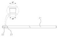
도 1 은 본 발명 레일 클램퍼의 레일 장착상태 사시도,
도 2 는 본 발명 레일 클램퍼의 레일 장착상태 상세사시도,
도 3 은 본 발명 레일 클램퍼의 사시도로서, 도 3a 는 상부 사시도, 도 3b 는 하부 사시도,
도 4 는 본 발명 레일 클램퍼의 종단면도,
도 5 는 본 발명 레일 클램퍼의 횡단면도,
도 6 은 본 발명 레일 클램퍼의 분해사시도,
도 7 은 본 발명 레일 클램퍼의 걸림부의 정면도, 측면도 및 저면도,
도 8 은 본 발명 레일 클램퍼의 고정블럭을 도시한 것으로서, 도 8a 는 고정블럭의 사시도, 도 8b 는 고정블럭의 측면도,
도 9 는 본 발명 레일 클램퍼의 누름블럭을 도시한 것으로서, 도 9a 는 누름블럭의 배면사시도, 도 9b 는 누름블럭의 정면사시도,
도 10 은 본 발명 레일 클램퍼의 누름판을 도시한 것으로서, 도 10a 는 누름판의 배면사시도, 도 10b 는 누름판의 정면사시도,
도 11 은 본 발명 레일 클램퍼의 푸쉬암의 단면도,
도 12 는 본 발명 레일 클램퍼의 수직바에 장착되는 연결 유닛의 사시도,
도 13 은 도 12 의 연결 유닛의 단면도,
도 14 는 본 발명 레일 클램퍼의 수직바를 도시한 것으로서, 도 14a 는 수직바의 사시도, 도 14b 는 수직바의 측면도, 도 14c 는 수직바의 저면도이다.BRIEF DESCRIPTION OF THE DRAWINGS FIG. 1 is a perspective view of a rail-
2 is a detailed perspective view of a rail mounting state of a rail clamper according to the present invention,
Fig. 3 is a perspective view of a rail clamper according to the present invention, Fig. 3a is an upper perspective view, Fig. 3b is a lower perspective view,
4 is a longitudinal sectional view of the rail clamper according to the present invention,
Figure 5 is a cross-sectional view of the rail clamper of the present invention,
6 is an exploded perspective view of the rail clamper of the present invention,
FIG. 7 is a front view, a side view, and a bottom view of the engagement portion of the rail clamper of the present invention,
FIG. 8 is a perspective view of a fixed block of a rail clamper according to the present invention, FIG. 8A is a perspective view of a fixed block, FIG. 8B is a side view of a fixed block,
9A is a rear perspective view of a press block, FIG. 9B is a front perspective view of a press block, FIG.
10A and 10B are perspective views of a press plate, FIG. 10B is a front perspective view of a press plate, FIG.
11 is a sectional view of a push arm of a rail clamper according to the present invention,
Figure 12 is a perspective view of a connecting unit mounted on a vertical bar of a rail clamper of the present invention,
Figure 13 is a cross-sectional view of the connecting unit of Figure 12,
Fig. 14 shows a vertical bar of the rail clamper according to the present invention. Fig. 14A is a perspective view of the vertical bar, Fig. 14B is a side view of the vertical bar, and Fig. 14C is a bottom view of the vertical bar.
이하, 첨부 도면에 의거하여 본 발명 병원 침상용 레일 클램퍼의 구성 및 작동을 상세하게 설명한다.Hereinafter, the construction and operation of the rail clamper for a hospital hospital needle bed will be described in detail with reference to the accompanying drawings.
단, 개시된 도면들은 당업자에게 본 발명의 사상이 충분하게 전달될 수 있도록 하기 위한 예로서 제공되는 것이다. 따라서, 본 발명은 이하 제시되는 도면들에 한정되지 않고 다른 태양으로 구체화될 수도 있다.It is to be noted, however, that the disclosed drawings are provided as examples for allowing a person skilled in the art to sufficiently convey the spirit of the present invention. Accordingly, the present invention is not limited to the following drawings, but may be embodied in other forms.
또한, 본 발명 명세서에서 사용되는 용어에 있어서 다른 정의가 없다면, 본 발명이 속하는 기술 분야에서 통상의 지식을 가진 자가 통상적으로 이해하고 있는 의미를 가지며, 하기의 설명 및 첨부 도면에서 본 발명의 요지를 불필요하게 흐릴 수 있는 공지 기능 및 구성에 대한 상세한 설명은 생략한다.
In addition, unless otherwise defined, the terms used in the description of the present invention have the same meaning as commonly understood by one of ordinary skill in the art to which the present invention belongs. In the following description and the accompanying drawings, A detailed description of known functions and configurations that may be unnecessarily blurred is omitted.
도 1 은 본 발명 레일 클램퍼의 레일 장착상태 사시도이다.BRIEF DESCRIPTION OF THE DRAWINGS Fig. 1 is a perspective view of a rail-mounted rail clamper according to the present invention.
본 발명 레일 클램퍼(1)는 병원에서 사용되는 침상(10)의 측면(12)에 부착된 레일(50)에 결합되는 장치이다.The
상기와 같은 클램퍼(1)는 그 상부에 수직바(20)를 고정시키고, 상기 수직바(20)에 연결유닛(30)을 결합시키되, 이 연결유닛(30)에 계측장비나 수술장비 또는 검사장비를 고정시키는 거치유닛(60)을 말단에 고정시킨 앵글바(40)를 결합시키게 된다.The
아울러, 상기 클램퍼(1)는 이와 같이 설치된 상태에서 침상(10)의 상면(11)에 누운 환자를 검사하거나 치료하기 위하여, 클램퍼(1)와 상기 레일(50)과의 결합상태를 일시적으로 해제시켜 클램퍼(1)를 침상(10)의 전면(13) 방향인 전방 방향 또는 전면(13)의 반대 방향인 후면 방향으로 이동시킬 수 있으며, 이에 따라서 클램퍼(1)의 수직바(20)와 앵글바(40)를 통하여 연결된 거치유닛(60)에 고정된 계측 장비나 수술장비 또는 검사장비를 환자의 필요한 신체부위 상으로 이동시킬 수 있다.
The
도 2 는 상기의 본 발명 클램퍼(1)가 레일(50)에 결합된 상태를 보다 상세하게 나타낸 도면이다.2 is a view showing the
상술한 바와 같이, 본 발명 클램퍼(1)는 침상(10)의 측면(12)에 부착돌기(51)에 의하여 부차된 레일(50)에 결합되는 장치로서, 상기 클램퍼(1)는 주된 몸체를 이루되 고정된 상태의 상부턱(110)과 상하방향으로 이동가능한 하부턱(120)이 레일(50)의 상측과 하측에 각각 걸려짐으로써 클램퍼(1)를 레일(50) 상에 걸려지게 하는 걸림부(100)를 포함한다.As described above, the
또한, 본 발명 클램퍼(1)는 상기와 같이 클램퍼(1)가 상부턱(110)과 하부턱(120)에 의하여 레일(50)에 걸려진 상태에서 클램퍼(1)를 보다 공고하게 레일(50)에 결합시키기 위하여 클램퍼(1) 몸체를 레일(50)의 표면(52)과 밀착시키는 누름부(200)를 포함한다.The
또한, 본 발명 클램퍼(1)는 상기 걸림부(100)와 누름부(200)에 의하여 레일(50)에 고정된 상태에서 수직바(20)를 클램퍼(1)에 결합시키는 고정부(300)를 포함한다.The
그리고, 상기의 걸림부(100)의 걸림 작동을 위하여 하부턱(120)을 이동시키는 걸림부 조절나사(130)가 클램퍼(1) 몸체 하부에 설치되고, 상기 누름부(200)의 누름 작동을 위하여 후술할 누름블럭(210)을 이동시키는 누름부 조절나사(230)가 클램퍼(1) 몸체 중앙에 설치되고, 상기 수직바(20)를 클램퍼(1)의 몸체에 결합시키는 고정부 조절나사(330)가 클램퍼(1) 몸체 상부에 설치된다.An engaging
한편, 상기 걸림부(100), 누름부(200) 및 고정부(300)의 재질은 금속재로 형성하되 바람직하게는, 강성과 내부식성이 양호한 스테인레스 스틸 재질인 것이 좋다.
The
이하, 상기와 같이 구성되는 본 발명 클램퍼(1)의 상세한 구성을 도면을 참조하여 설명한다.Hereinafter, the detailed configuration of the
도 3 은 본 발명 레일 클램퍼의 걸림부 사시도로서, 도 3a 는 상부 사시도, 도 3b 는 하부 사시도, 도 4 는 본 발명 레일 클램퍼의 종단면도, 도 5 는 본 발명 레일 클램퍼의 횡단면도, 도 6 은 본 발명 레일클램퍼의 분해사시도이다.Fig. 3 is a perspective view of a latching portion of a rail clamper according to the present invention, Fig. 3a is an upper perspective view, Fig. 3b is a lower perspective view, Fig. 4 is a vertical cross- An inventive rail clamper is an exploded perspective view.
도면을 참조하면, 본 발명 레일 클램퍼(1)의 주요 몸체를 이루는 걸림부(100)의 전방에 형성된 요입면(101)에 누름부조절나사(230)의 조작에 따라서 전후방향으로 이동가능한 누름블럭(210)이 거치되고, 걸림부(100)의 후방에 레일(50)의 상측에 걸려지는 상부턱(110)이 클램퍼(1) 몸체와 일체로 형성된다.1 is a perspective view of a rail clamper according to a first embodiment of the present invention. FIG. 2 is a perspective view of a rail clamper according to a first embodiment of the present invention. An
또한, 상기 걸림부(100)의 후방에 레일(50)의 하측에 걸려지는 하부턱(120)이 결합되고, 상기 하부턱(120)은 걸림부(100)의 바닥면으로부터 상부턱(110) 방향으로 상하방향으로 이동가능하게 결합된다.The
이를 위하여 하부턱(120)의 후단에 요철 형상의 치합면(123)이 형성되고, 상기 걸림부(100)의 바닥면 내부에 요철 형상의 치합면(102)이 각각 형성된다.To this end, a
상기 상부턱(110)과 하부턱(120)은 각각 'ㄱ'자 형상으로 이루어지되, 상기 상부턱(110)의 말단은 수직 하방으로 절곡된 내측면이 레일(50)의 상측에 물려지는 물림면(111)이 형성되고, 상기 하부턱(120)의 말단은 수직 상방으로 절곡된 내측면이 레일(50)의 하측에 물려지는 물림면(121)이 형성된다.Each of the upper and
또한, 상기 하부턱(120)의 이동거리의 조절을 위하여 걸림부조절나사(130)가 하부턱(120)의 후단에 형성된 관통공(122)으로 삽입되어 걸림부(100)의 저면에 형성된 통공(181)으로 진입하며, 상기 관통공(122)의 내측벽면에는 후술할 제 1 나사봉(150)의 나사산(151)과 치합되는 나사산이 형성되어 있다.The
상기 하부턱(120)에 삽입된 걸림부조절나사(130)는 조절나사를 회전시키는 제 1 헤드(140)와 상기 제 1 헤드(140)에 결합된 제 1 나사봉(150)과, 상기 제 1 나사봉(150)의 말단에 형성되어 상기 하부턱(120)의 상부 표면에 걸려지는 제 1 걸림구(160)로 이루어져 있다.The engaging
상기 제 1 걸림구(160)는 상부걸림턱(161)과 하부걸림턱(162)을 가진 피스톤 형상으로서, 상기 상부걸림턱(161)과 하부걸림턱(162) 사이에 한쌍의 제 1 고정핀(170)이 게재된다.The
따라서, 상기 걸림부조절나사(130)는 사용자가 제 1 헤드(140)를 회전시키면 제 1 나사봉(150)과 제 1 걸림구(160)가 제 1 고정핀(170)에 걸려진 채 걸림부(100)의 내부 공간에서 제자리에서 시계방향 또는 시계반대방향으로 회전을 하게 되는데, 이 제 1 나사봉(150)의 회전에 따라서 이와 나사결합된 하부턱(120)이 상방 또는 하방으로 이동하게 되는 것이다.Accordingly, when the user rotates the
이때, 상기 걸림부조절나사(130)의 제 1 걸림구(160)에 게재되는 한쌍의 제 1 고정핀(170)은 도 7 의 걸림부(100)의 배면도에 도시된 바와 같이 걸림부(100)의 배면 몸체상에 형성된 한쌍의 제 1 고정핀 삽입공(171,172)에 각각 삽입되어 걸림부(100) 몸체 내부로 삽입된다.A pair of first fixing pins 170 disposed on the
또한, 상기 걸림부(100)의 전방의 요입면(101)에 거치된 누름블럭(210)에 누름판(220)을 전후방향으로 이동시켜 누름판(220)을 레일(50)에 밀착 고정시키는 누름부조절나사(230)가 누름블럭(210)의 나사삽입공(211)으로 삽입되어 걸림부(100)의 정면에 형성된 통공(180)을 통하여 걸림부(100)의 내부공간으로 진입한다.The pushing
상기 누름부조절나사(230)는 조절나사를 회전시키는 제 2 헤드(240)와 상기 제 2 헤드(240)에 결합된 제 2 나사봉(250)과, 상기 제 2 나사봉(250)의 말단에 형성된 제 2 걸림구(260)로 이루어져 있다.The
상기 제 2 걸림구(260)는 상부걸림턱(261)과 하부걸림턱(262)을 가진 피스톤 형상으로서, 상기 상부걸림턱(261)과 하부걸림턱(262) 사이에 한쌍의 제 2 고정핀(270)이 게재된다.The
따라서, 상기 누름부조절나사(230)는 사용자가 제 2 헤드(240)를 회전시키면 제 2 나사봉(250)과 제 2 걸림구(260)가 제 2 고정핀(270)에 걸려진 채 걸림부(100)의 내부 공간에서 제자리에서 시계방향 또는 시계반대방향으로 회전을 하게 되는데, 이 제 2 나사봉(250)의 회전에 따라서 이와 나사결합된 누름블럭(210)이 전방 또는 후방으로 이동하게 된다.Therefore, when the user rotates the
이때, 상기 누름부조절나사(230)의 제 2 걸림구(260)에 게재되는 한쌍의 제 2 고정핀(270)은 도 7 의 걸림부(100)의 저면도에 도시된 바와 같이 걸림부(100)의 저면 몸체상에 형성된 한쌍의 제 2 고정핀 삽입공(271,272)에 각각 삽입되어 걸림부(100) 몸체 내부로 삽입된다.At this time, the pair of second fixing pins 270 disposed on the
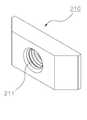
한편, 상기와 같은 누름블럭(210)의 전방 또는 후방으로의 이동에 따라서 걸림부(100)의 후방에 설치되는 누름판(220)도 전방 또는 후방으로 이동하게 되는데, 이를 위하여 도 9a 및 도 9b 에 도시된 바와 같이 상기 누름블럭(210)의 배면 좌우측에 형성된 삽입구(212,212')에 한쌍의 푸쉬암(280,280')이 삽입되어 고정된다.9 (a) and 9 (b), the pushing
상기 푸쉬암(280,280')은 그 일측이 상술한 바와 같이 누름블럭(210)에 고정되며, 그 타측은 걸림부(100)의 몸체 중앙에 형성된 관통구(190,190')를 통하여 걸림부(100)의 배면으로 노출된다.One side of the
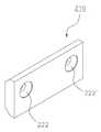
그리고, 도 10a 및 도 10b 에 도시된 바와 같이 누름판(220)의 전면에 형성된 한쌍의 결합구(221,221')에 걸림부(100) 배면으로 노출된 상기 푸쉬암(280,280')의 타측이 각각 삽입된다.As shown in FIGS. 10A and 10B, the other side of the
또한, 결합구(221,221') 중앙에 형성된 볼트삽입공(222,222')에 삽입되는 볼트(미도시)가 도 11 에 도시된 푸쉬암(280,280')의 내부에 형성된 핀홀(281)에 요입됨으로써 푸쉬암(280,280')이 누름판(220)과 공고하게 결합된다.A bolt (not shown) inserted into the bolt insertion holes 222 and 222 'formed at the centers of the coupling holes 221 and 221' is inserted into the
따라서, 상기 누름부조절나사(240)에 의하여 전후방향으로 이동되는 누름블럭(210)에 의하여 누름블럭(210)에 고정되어 걸림부 배면으로 관통한 푸쉬암(280,280')에 고정된 상태의 누름판(220)도 누름블럭(210)의 전후방향의 이동과 연동되어 함께 전후방향으로 이동되고, 이에 따라서 누름판(220)이 레일(50)의 표면(52)에 밀착되거나 표면(52)으로부터 이격될 수 있게 되는 것이다.The pushing
또한, 본 발명 클램퍼(1)의 걸림부(100)의 상부에 수직바(20)를 삽입 고정시키는 고정부(300)가 설치되며, 상기 고정부(300)는 걸림부(100) 상부 표면과 일체로 형성된 박스형상의 금구(103) 내부의 내부공(301)에 요입되어 거치되는 고정블럭(380)을 포함하고 있다.A fixing
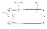
상기 고정블럭(380)는 도 8a 및 도 8b 에 도시된 바와 같이, 몸체(382)의 정면에 고정부조절나사(330)가 삽입되는 관통공(381)이 형성되고, 몸체(382)의 배면에는 갈래 형상이되 도 14a, 도 14b 및 도 14c 에 도시된 수직바(20)의 봉체(21)의 일측에 형성된 한쌍의 요홈(22)으로 슬라이드 결합되는 한쌍의 삽입편(383,384)이 형성되고, 상기 삽입편(383,384)의 사이의 중공면(386)에 수직바(20)의 봉체(21)의 일측단이 삽입되고, 삽입된 수직바(20)의 봉체(21) 일측단이 관통공(381)으로 진입한 고정부조절나사(330)의 보스(boss)(363)와 맞물려지면서 수직바(20)가 공고하게 본 발명 클램퍼(1)에 고정된다.8A and 8B, the fixing
여기서, 도 8b 에 도시된 바와 같이, 상기 고정블럭(380)의 일측 삽입편(383)의 최상단부터 타측 삽입편(384)의 최하단까지의 높이(h2)는 몸체(382)의 높이(h1) 보다 적으며, 잔여 2 부분의 높이(h3)와 합산하여야 몸체(382)의 높이(h1)와 동일하도록 형성되어 전체적으로 각 삽입편(383,384)의 말단 부분 형상 이 사다리꼴 형상으로 형성되었는데, 이러한 각 삽입편(383,384)의 사다리꼴 형상은 상기 수직바(20)의 형성된 한쌍의 요홈(22)의 형상을 사다리꼴로 형성함으로써, 고정블럭(380)과 결합하는 수직바(20)의 고정력을 보다 공고하게 하기 위함이다.8B, the height h2 from the uppermost end of the one
한편, 상기 고정부(380)의 금구(103) 내부에 상기 고정블럭(380)이 거치된 상태에서 금구(103)의 전방은 전면 고정판(310)에 의하여 차폐되고, 그 후방은 후면 고정판(320)에 의하여 차폐된다.In the state where the fixing
이를 위하여 상기 전면고정판(310)에는 고정볼트(미도시)가 삽입되는 볼트삽입구(312)가 형성되고, 상기 전면고정판(310)의 볼트삽입구(312)로 삽입된 볼트 몸체가 금구(103)의 통공(302)을 통과하여 후면고정판(320)의 볼트요입구(321)로 요입되어 전면고정판(310) 및 후면고정판(320)이 금구(103)에 결합된다.The
이때, 상기 후면고정판(320)에는 상기 고정블럭(380)의 각 삽입편(383,384)에 형성된 홈(387)에 삽입되는 삽입돌기(322)가 형성되어 고정블럭(380)을 금구(103)의 내부공(301)에서 보다 공고하게 거치시킬 수 있게 된다.An
또한, 상기 고정부(300)는 전면고정판(310)의 나사삽입공(311)을 통하여 고정부조절나사(330)가 삽입되어 금구(103) 내부로 진입한다.The fixing
상기 고정부조절나사(330)는 조절나사를 회전시키는 제 3 헤드(340)와, 상기 제 3 헤드(340)에 결합된 제 3 나사봉(350)과, 상기 제 3 나사봉(350)의 말단에 형성되어 상기 고정블럭(380)의 삽입편(383,384)의 사이의 중공면(386)에 걸려지는 제 3 걸림구(360)로 이루어져 있다.The fixing
상기 제 3 걸림구(360)는 상부걸림턱(361)과 하부걸림턱(362)을 가진 피스톤 형상으로서, 상기 상부걸림턱(361)과 하부걸림턱(362) 사이에 한쌍의 제 3 고정핀(370)이 게재된다.The
따라서, 상기 고정부조절나사(330)는 사용자가 제 3 헤드(340)를 회전시키면 제 3 나사봉(350)과 제 3 걸림구(360)가 제 3 고정핀(370)에 걸려진 채 고정블럭(380)의 삽입편(383,384) 사이의 중공면(386)에서 제자리에서 시계방향 또는 시계반대방향으로 회전을 하면서 상기 제 3 걸림구(360)의 말단에 형성된 보스(363)를 전방 또는 후방으로 이동시켜 수직바(20)의 봉체(21)의 일측단에 밀착 고정시키거나 해제시키게 되는 것이다.Therefore, when the user rotates the
이때, 상기 고정부조절나사(330)의 제 3 걸림구(360)에 게재되는 한쌍의 제 3 고정핀(370)은 도 8 의 도시된 고정블럭(380)의 몸체(382) 상부에 형성된 한쌍의 제 3 고정핀 삽입공(385)에 각각 삽입된다.At this time, a pair of third fixing pins 370 disposed on the
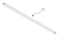
한편, 상기 고정부(300)에 의하여 결합되는 수직바(20)는 도 14c 에 도시된 바와 같이 핀 요입홀(23)이 형성되어 있는데, 상기 핀 요입홀(23)은 상술한 바와 같이 수직바(20)를 금구(103)의 상부에 형성된 수직바 요입구(390)를 통하여 금구(103) 내부로 진입시켜 고정블럭(380)에 고정시킬 경우, 상기 고정블럭(380)의 일측 삽입편(383) 및 타측 삽입편(384)과 수직바(20)의 요홈(22)과의 결합 방향을 맞추기 위하여 형성된 것이다.As shown in FIG. 14C, the
상기와 같이 구성되는 본 발명 클램퍼(1)에 고정된 수직바(20)에는 전술한 바와 같이, 연결유닛(30)이 결합된다.The connecting
도 12 의 연결유닛(30)의 사시도 및 도 13 의 그 단면도에 도시된 바와 같이, 상기 연결유닛(30)은 핸들(31)과 상기 핸들(31) 내부에 삽입고정되는 나사(38)에 순차적으로 결합되는 한쌍의 수직바 결합부(32,33)과 한쌍의 앵글바 결합부(34,35)로 구성된다.The
상기 수직바 결합부(32,33)의 측부에는 수직바(20)를 관통시키는 수직공(36)이 형성되고, 상기 앵글바 결합부(34,35)의 측부에는 앵글바(40)를 관통시키는 수평공(37)이 형성되며, 상기 수직바 결합부와 앵글바 결합부가 상호 접촉되는 일측의 수직바 결합부(33)와 일측의 수평바 결합부(34)의 상호 접촉면에는 톱니 형상의 래치(latch)(33a,34a)가 각각 형성되어, 상기 핸들(31)의 조작에 따라서 상기 수직바 결합부(32,33)와 앵글바 결합부(34,35)에 삽입되는 수직바(20)와 앵글바(40)를 공고하게 고정시킬 수 있다.
A
상기와 같이 구성되는 본 발명 클램퍼(1)는 전술한 도 2 에 도시된 바와 같이, 침상(10)의 측면(12)에 설치된 레일(50)의 상측에 클램퍼(1)의 걸림부(100)의 상부턱(110)의 물림면(111)을 걸리게 한 후, 걸림부조절나사(130)의 헤드(140)를 회전시켜 하부턱(120)을 상방으로 이동시켜 레일(50)의 하측 부분을 하부턱(120)의 물림면(121)에 밀착시켜 클램퍼(1) 몸체를 레일(50)에 결합시킨다.2, the
다음으로, 상기와 같이 레일(50)에 결합된 클램퍼(1)의 결합 상태를 보다 공고하게 조성하기 위하여, 걸림부(100)의 전면에 설치된 누름부조절나사(230)의 헤드(240)를 회전시켜 누름블럭(210)을 후방으로 이동시키면, 상기 누름블럭(210)에 결합된 한쌍의 푸쉬암(280,280')도 후방으로 이동되면서 푸쉬암(280,280')에 결합되어 걸림부(100) 배면으로 노출된 누름판(220)이 후방으로 이동하면서 상기 레일(50)의 표면(52)에 누름판(220)이 밀착되고 이러한 누름판(220)과 레일 표면(52)과의 밀착 작용으로 상기 클램퍼(1)가 레일(50)에 공고하게 결합되게 된다.The
이어서, 상기와 같이 레일(50)에 공고하게 결합된 클램퍼(1)의 몸체 상부에 형성된 고정부(300)의 수직바 요입구(390)로 수직바(20)의 봉체(21) 일측단을 삽입시킨다.A
그리고, 수직바(20)의 핀 요입홀(23)을 기준으로 상기 고정블럭(380)의 일측 삽입편(383) 및 타측 삽입편(384)과 수직바(20)의 요홈(22)과의 결합 방향을 맞춘다.The one
이때, 상기 봉체(21)에 일측단에 형성된 사다리꼴 형상의 요홈(22)은 그 상부 길이(g1)가 그 하부길이(g2)보다 더 긴 사다리꼴 형상인데, 이 사다리꼴 형상의 요홈(22)으로 상기 고정부(300)의 고정블럭(380)의 사다리꼴 형상의 삽입편(383,384)을 슬라이드 요입시켜 고정블럭(380)과 결합하는 수직바(20)의 고정력을 보다 강화시킨다.The
이후, 고정부조절나사(330)의 헤드(340)를 조절하여 조절나사(330)의 제 3 걸림구(360)의 말단에 형성된 보스(boss)(363)를 수직바(20)의 봉체(21)의 일측단에 밀착 고정시켜 고정부(300)에 수직바(20)를 공고하게 결합시킨다.The
추가적으로, 금구(103) 상면에 형성된 요홈(391)으로 고정핀(미도시)를 진입시켜 봉체(21)의 핀 요입홀(23)로 삽입시킴으로써, 수직바(20)의 고정력을 보다 강화시키는 것도 좋다.In addition, a fixing pin (not shown) may be inserted into a
이후, 상기와 같이 본 발명 클램퍼(1)에 결합된 수직바(20)의 연결유닛(30)에 앵글바(40)가 고정되고, 이 앵글바(40)에 계측장비나 수술장비 또는 검사장비를 고정시키는 거치유닛(60)을 설치하며, 거치유닛(60)은 이에 사용되는 계측장비나 수술장비 또는 검사장비에 따라서 다양한 종류의 것들을 사용할 수 있다.The
한편, 본 발명 클램퍼(1)로부터 수직바(20)를 해제시키거나 클램퍼(1)의 위치를 레일(50)상에서 이동시키고자 하면, 상기 결합되는 순서를 역순으로 이행하여 본 발명 클램퍼(1)의 고정부(300)와 누름부(200) 및 걸림부(100)의 작용을 역순으로 해제하면 되므로, 그 상세한 설명은 생략한다.
When the
이상의 설명에서 본 발명의 병원 침상용 레일 클램퍼의 구성 및 작동을 첨부된 도면을 참조하여 상세하게 설명하였으나, 본 발명은 당업자에 의하여 다양한 수정, 변경 및 치환이 가능하고, 이러한 수정, 변경 및 치환은 본 발명의 보호범위에 속하는 것으로 해석되어야 한다.While the present invention has been particularly shown and described with reference to exemplary embodiments thereof, it is to be clearly understood that the same is by way of illustration and example only and is not to be taken by way of limitation, And should be construed as falling within the scope of protection of the present invention.
* 도면의 주요 부분에 대한 부호의 설명 *
1; 본 발명 레일 클램퍼
10; 침상
11; 상면12; 측면
13; 전면
20; 수직바 30; 연결유닛
40; 앵글바50; 레일
51; 부착돌기 52; 레일 표면
60; 거치유닛100; 걸림부
101; 요입면102; 치합면
103; 금구
110; 상부턱 120; 하부턱
130; 걸림부 조절나사
140; 제 1 헤드150; 제 1 나사봉
151; 나사산 160; 제 1 걸림구
161; 상부걸림턱162; 하부걸림턱
170; 제 1 고정핀
171,172; 제 1 고정핀 삽입공
180; 누름부조절나사 통공
181; 걸림부조절나사 통공
190,190'; 푸시암 관통구
200; 누름부 210; 누름 블럭
211; 나사 삽입공212,212'; 푸시암 삽입구
220; 누름판
221,221'; 푸쉬암 결합구222,222'; 볼트 삽입공
230; 누름부 조절나사
240; 제 2 헤드250; 제 2 나사봉
260; 제 2 걸림구
261; 상부걸림턱 262; 하부걸림턱
270; 제 2 고정핀
271,272; 제 2 고정핀 삽입옥
280.280'; 푸쉬암300; 고정부
301; 내부공302; 통공
310; 전면 고정판311; 나사 삽입공
312; 볼트 삽입구320; 후면 고정판
321; 볼트 삽입구322; 삽입돌기
330; 고정부 조절나사340; 제 3 헤드
350; 제 3 나사봉 360; 제 3 걸림구
361; 상부걸림턱362; 하부걸림턱
363; 고정 보스370; 제 3 고정핀
380; 고정블럭Description of the Related Art [0002]
One; The rail clamper
10; couch
11;
13; Front
20;
40;
51; An
60; A mounting
101;
103; Bracket
110; An
130; Retaining screw
140; A
151;
161;
170; The first fixing pin
171,172; The first fixing pin insertion hole
180; Presser adjusting screw hole
181; Threaded adjustment screw through hole
190,190 '; Push arm penetration hole
200; A
211; Screw insertion holes 212 and 212 '; Push arm insertion hole
220; Presser plate
221,221 '; Push
230; Pusher adjusting screw
240; A
260; The second stop
261;
270; The second fixing pin
271,272; The second fixing pin insertion jaw
280.280 '; A
301;
310; Front fixed
312;
321;
330; Fixing
350; The
361; An
363; Fixed
380; Fixed block
Claims (7)
Translated fromKorean클램퍼의 몸체를 이루되, 고정된 상태의 상부턱(110)과 상하방향으로 이동가능한 하부턱(120)이 레일(50)의 상측과 하측에 각각 걸려지는 걸림부(100);
상기 걸림부(100)에 거치된 누름블럭(210)을 전후방향으로 이동시켜 누름블럭(210)과 연결된 누름판(220)을 상기 레일(50)의 표면(52)에 밀착시키는 누름부(200);
상기 걸림부(100)의 상부에 일체로 형성되어 수직바(20)를 삽입 고정시키는 고정부(300); 를 포함하여 구성되고,
상기 걸림부(100)의 하부턱(120)을 이동시키는 걸림부 조절나사(130)가 걸림부(100)의 하부에 설치되고,
상기 누름부(200)의 누름블럭(210)을 이동시키는 누름부 조절나사(230)가 걸림부(100)의 중앙부에 설치되고,
상기 고정부(300)에 상기 수직바(20)를 고정시키는 고정부 조절나사(330)가 설치되는 것을 특징으로 하는 레일 클램퍼.
A clamper coupled to a rail (50) attached to a needle bed (10)
A locking part 100 which is a body of the clamper and in which the upper jaw 110 in the fixed state and the lower jaw 120 movable in the vertical direction are hooked on the upper and lower sides of the rail 50, respectively;
A pressing part 200 for moving the pressing block 210 mounted on the locking part 100 in the forward and backward direction and pressing the pressing plate 220 connected to the pressing block 210 against the surface 52 of the rail 50, ;
A fixing part 300 integrally formed on the upper part of the locking part 100 to insert and fix the vertical bar 20 therein; And,
A retaining portion adjusting screw 130 for moving the lower jaw 120 of the retaining portion 100 is installed at a lower portion of the retaining portion 100,
A pressing part adjusting screw 230 for moving the pressing block 210 of the pressing part 200 is provided at a central part of the engaging part 100,
And a fixing part (330) for fixing the vertical bar (20) to the fixing part (300).
상기 하부턱(120)에 걸림부조절나사(130)가 삽입되고,
상기 걸림부조절나사(130)는 제 1 헤드(140)와 상기 제 1 헤드(140)에 결합된 제 1 나사봉(150)과, 상기 제 1 나사봉(150)의 말단에 형성되어 상기 하부턱(120)의 상부 표면에 걸려지는 제 1 걸림구(160)로 이루어지고,
상기 제 1 걸림구(160)의 상부걸림턱(161)과 하부걸림턱(162) 사이에 한쌍의 제 1 고정핀(170)이 게재되고,
상기 제 1 나사봉(150)의 회전에 따라서 상기 하부턱(120)이 상방 또는 하방으로 이동하는 것을 특징으로 하는 레일 클램퍼.
2. The apparatus according to claim 1, wherein the engaging portion (100)
A latching part 130 is inserted into the lower jaw 120,
The retaining portion adjusting screw 130 includes a first head 140 and a first screw rod 150 coupled to the first head 140. The first screw rod 150 is formed at a distal end of the first screw rod 150, And a first latching part 160 which is engaged with the upper surface of the jaw 120,
A pair of first fixing pins 170 are disposed between the upper locking protrusion 161 and the lower locking protrusion 162 of the first locking protrusion 160,
And the lower jaw (120) moves upward or downward according to the rotation of the first screw rod (150).
상기 누름부조절나사(230)가 누름블럭(210)의 나사삽입공(211)으로 삽입되어 걸림부(100)의 정면에 형성된 통공(180)을 통하여 걸림부(100)의 내부공간으로 진입하고,
상기 누름부조절나사(230)는 제 2 헤드(240)와 상기 제 2 헤드(240)에 결합된 제 2 나사봉(250)과, 상기 제 2 나사봉(250)의 말단에 형성된 제 2 걸림구(260)로 이루어지고,
상기 제 2 걸림구(260)의 상부걸림턱(261)과 하부걸림턱(262) 사이에 한쌍의 제 2 고정핀(270)이 게재되고,
상기 제 2 나사봉(250)의 회전에 따라서 상기 누름블럭(210)이 전방 또는 후방으로 이동하는 것을 특징으로 하는 레일 클램퍼.The apparatus of claim 1, wherein the pusher (200)
The pressing part adjusting screw 230 is inserted into the screw insertion hole 211 of the pressing block 210 and enters the inner space of the engaging part 100 through the through hole 180 formed in the front face of the engaging part 100 ,
The presser adjusting screw 230 includes a second head 240 and a second threader 250 coupled to the second head 240. The second threader 250 is coupled to the second head 240, (260)
A pair of second fixing pins 270 are disposed between the upper locking jaw 261 and the lower locking jaw 262 of the second locking hole 260,
And the push block (210) moves forward or backward according to the rotation of the second threaded rod (250).
상기 누름블럭(210)의 배면 좌우측에 형성된 삽입구(212,212')에 한쌍의 푸쉬암(280,280')의 일측이 삽입 고정되고,
상기 푸쉬암(280,280')의 타측은 걸림부(100)의 몸체 중앙에 형성된 관통구(190,190')를 통하여 걸림부(100)의 배면으로 노출되어 누름판(220)의 전면에 형성된 한쌍의 결합구(221,221')에 각각 삽입되어 고정되는 것을 특징으로 하는 레일 클램퍼.
The method of claim 3,
One side of a pair of push arms 280 and 280 'is inserted and fixed to the insertion ports 212 and 212' formed on the left and right sides of the back surface of the push block 210,
The other side of the push arms 280 and 280 'is exposed through the through holes 190 and 190' formed at the center of the body 100 of the locking part 100 to the back side of the locking part 100, (221, 221 '), respectively.
걸림부(100) 상부에 형성된 금구(103)의 전면을 차폐하는 전면고정판(310)의 나사삽입공(311)을 통하여 삽입된 고정부조절나사(330)가 상기 금구(103) 내부에 거치된 고정블럭(380)으로 진입하고,
상기 고정부조절나사(330)는 제 3 헤드(340)와, 상기 제 3 헤드(340)에 결합된 제 3 나사봉(350)과, 상기 제 3 나사봉(350)의 말단에 형성된 제 3 걸림구(360)로 이루어지고,
상기 제 3 걸림구(360)의 상부걸림턱(361)과 하부걸림턱(362) 사이에 한쌍의 제 3 고정핀(370)이 게재되고,
상기 제 3 나사봉(350)의 회전에 따라서 상기 제 3 걸림구(360)의 말단에 형성된 보스(363)가 전방 또는 후방으로 이동되는 것을 특징으로 하는 레일 클램퍼.
2. The apparatus of claim 1, wherein the fixing unit (300)
The fixing part fixing screw 330 inserted through the screw insertion hole 311 of the front fixing plate 310 shielding the front surface of the metal part 103 formed on the locking part 100 is inserted into the metal part 103 Enters the fixed block 380,
The fixing screw 330 includes a third head 340, a third screw thread 350 coupled to the third head 340, and a third screw thread 350 formed at a distal end of the third screw rod 350. [ And a latching part 360,
A pair of third fixing pins 370 are disposed between the upper latching jaw 361 and the lower latching jaw 362 of the third latching member 360,
And the boss (363) formed at the end of the third stopping hole (360) is moved forward or backward according to the rotation of the third screw rod (350).
몸체(382)의 정면에 고정부조절나사(230)가 삽입되는 관통공(381)이 형성되고, 몸체(382)의 배면에는 갈래 형상이되 상기 수직바(20)의 봉체(21)의 일측에 형성된 한쌍의 요홈(22)으로 슬라이드 결합되는 사다리꼴 형상의 한쌍의 삽입편(383,384)이 형성되고,
상기 삽입편(383,384)의 사이의 중공면(386)에 수직바(20)의 봉체(21)의 일측단이 삽입되고,
상기 상기 수직바(20)의 형성된 한쌍의 사다리꼴 형상의 요홈(22)으로 상기 삽입편(383,384)가 요입되는 것을 특징으로 하는 레일 클램퍼.
6. The apparatus of claim 5, wherein the fixed block (380)
A through hole 381 through which the fixing portion adjusting screw 230 is inserted is formed on the front surface of the body 382 and a bent portion is formed on the back surface of the body 382, A pair of trapezoidal insertion pieces 383 and 384 which are slidably coupled to a pair of grooves 22 formed in the base plate 30,
One end of the bar 21 of the vertical bar 20 is inserted into the hollow surface 386 between the insertion pieces 383 and 384,
Wherein the insert pieces (383, 384) are recessed into a pair of trapezoidal grooves (22) formed with the vertical bars (20).
Priority Applications (1)
| Application Number | Priority Date | Filing Date | Title |
|---|---|---|---|
| KR1020130062396AKR101435912B1 (en) | 2013-05-31 | 2013-05-31 | Rail clamper for a hospital bed |
Applications Claiming Priority (1)
| Application Number | Priority Date | Filing Date | Title |
|---|---|---|---|
| KR1020130062396AKR101435912B1 (en) | 2013-05-31 | 2013-05-31 | Rail clamper for a hospital bed |
Publications (1)
| Publication Number | Publication Date |
|---|---|
| KR101435912B1true KR101435912B1 (en) | 2014-09-01 |
Family
ID=51758904
Family Applications (1)
| Application Number | Title | Priority Date | Filing Date |
|---|---|---|---|
| KR1020130062396AExpired - Fee RelatedKR101435912B1 (en) | 2013-05-31 | 2013-05-31 | Rail clamper for a hospital bed |
Country Status (1)
| Country | Link |
|---|---|
| KR (1) | KR101435912B1 (en) |
Cited By (2)
| Publication number | Priority date | Publication date | Assignee | Title |
|---|---|---|---|---|
| CN116687698A (en)* | 2023-06-30 | 2023-09-05 | 北京威高智慧科技有限公司 | A leg support device |
| WO2025042075A1 (en)* | 2023-08-22 | 2025-02-27 | 고려대학교 산학협력단 | Device and method for making intravenous fluid stand usable on escalator |
Citations (4)
| Publication number | Priority date | Publication date | Assignee | Title |
|---|---|---|---|---|
| JPH0938078A (en)* | 1995-08-03 | 1997-02-10 | Toshiba Corp | Detaching device for sleeper |
| US20110121149A1 (en) | 2006-05-19 | 2011-05-26 | Arnold Herskovic | Clamping device |
| KR20110084180A (en)* | 2008-09-12 | 2011-07-21 | 케어퓨전 2200, 아이엔씨 | Bedrail Clamp |
| JP2013505064A (en) | 2009-09-17 | 2013-02-14 | アシスト・メディカル・システムズ,インコーポレイテッド | Apparatus and method for transfer of medical devices |
- 2013
- 2013-05-31KRKR1020130062396Apatent/KR101435912B1/ennot_activeExpired - Fee Related
Patent Citations (4)
| Publication number | Priority date | Publication date | Assignee | Title |
|---|---|---|---|---|
| JPH0938078A (en)* | 1995-08-03 | 1997-02-10 | Toshiba Corp | Detaching device for sleeper |
| US20110121149A1 (en) | 2006-05-19 | 2011-05-26 | Arnold Herskovic | Clamping device |
| KR20110084180A (en)* | 2008-09-12 | 2011-07-21 | 케어퓨전 2200, 아이엔씨 | Bedrail Clamp |
| JP2013505064A (en) | 2009-09-17 | 2013-02-14 | アシスト・メディカル・システムズ,インコーポレイテッド | Apparatus and method for transfer of medical devices |
Cited By (4)
| Publication number | Priority date | Publication date | Assignee | Title |
|---|---|---|---|---|
| CN116687698A (en)* | 2023-06-30 | 2023-09-05 | 北京威高智慧科技有限公司 | A leg support device |
| WO2025042075A1 (en)* | 2023-08-22 | 2025-02-27 | 고려대학교 산학협력단 | Device and method for making intravenous fluid stand usable on escalator |
| KR20250028718A (en)* | 2023-08-22 | 2025-03-04 | 고려대학교 산학협력단 | System, method enabling i.v pole on escalators |
| KR102804579B1 (en) | 2023-08-22 | 2025-05-07 | 고려대학교 산학협력단 | System, method enabling i.v pole on escalators |
Similar Documents
| Publication | Publication Date | Title |
|---|---|---|
| US6622980B2 (en) | Socket and rail clamp apparatus | |
| KR20100081995A (en) | Device for fitting a guide unit, and furniture part and piece of furniture having such a device | |
| US20140180348A1 (en) | Trajectory guide | |
| KR101435912B1 (en) | Rail clamper for a hospital bed | |
| CN101951808A (en) | Fixing device for locking furniture parts movably supported in or on furniture | |
| US20170143572A1 (en) | System and apparatus for reacting moments on a bed rail | |
| TW201249587A (en) | Clipping device | |
| CN105682584A (en) | spinal fixation device | |
| KR101443661B1 (en) | Device for removably fixing a current conductor to a current transformer housing | |
| JP2018537195A5 (en) | ||
| PH12015501826B1 (en) | Ear clip for medical monitoring device | |
| CN111494015A (en) | Mounting device for medical equipment | |
| KR200485319Y1 (en) | Fixing device of curtain for operating bed | |
| US20160066689A1 (en) | Device for the support and safe movement of cabinet doors | |
| CN206410901U (en) | A kind of sample clamp block locking device | |
| US10638836B2 (en) | Adjustment mechanism | |
| WO2011151009A1 (en) | Ankle clamp device to be affixed to an external fixation system | |
| CN108309671B (en) | A kind of anesthesia bed fastener fixator and its assembling, application method | |
| CN101564833A (en) | Reversing structure of ratchet wrench | |
| CN104840019B (en) | Slide rail assembly and connecting device for same | |
| CN212879499U (en) | A puncture-assisted fixation device | |
| TWI513434B (en) | Slide assembly and connecting device used for the same | |
| CN209203510U (en) | A kind of magnetic force accurately repeats positioning mechanism | |
| CN105476797B (en) | Modular surgical table surface backplate structure | |
| JP6726983B2 (en) | Drip stand connecting device |
Legal Events
| Date | Code | Title | Description |
|---|---|---|---|
| PA0109 | Patent application | St.27 status event code:A-0-1-A10-A12-nap-PA0109 | |
| PA0201 | Request for examination | St.27 status event code:A-1-2-D10-D11-exm-PA0201 | |
| D13-X000 | Search requested | St.27 status event code:A-1-2-D10-D13-srh-X000 | |
| D14-X000 | Search report completed | St.27 status event code:A-1-2-D10-D14-srh-X000 | |
| E701 | Decision to grant or registration of patent right | ||
| PE0701 | Decision of registration | St.27 status event code:A-1-2-D10-D22-exm-PE0701 | |
| GRNT | Written decision to grant | ||
| PR0701 | Registration of establishment | St.27 status event code:A-2-4-F10-F11-exm-PR0701 | |
| PR1002 | Payment of registration fee | St.27 status event code:A-2-2-U10-U11-oth-PR1002 Fee payment year number:1 | |
| PG1601 | Publication of registration | St.27 status event code:A-4-4-Q10-Q13-nap-PG1601 | |
| R18-X000 | Changes to party contact information recorded | St.27 status event code:A-5-5-R10-R18-oth-X000 | |
| P22-X000 | Classification modified | St.27 status event code:A-4-4-P10-P22-nap-X000 | |
| FPAY | Annual fee payment | Payment date:20170726 Year of fee payment:4 | |
| PR1001 | Payment of annual fee | St.27 status event code:A-4-4-U10-U11-oth-PR1001 Fee payment year number:4 | |
| LAPS | Lapse due to unpaid annual fee | ||
| PC1903 | Unpaid annual fee | St.27 status event code:A-4-4-U10-U13-oth-PC1903 Not in force date:20180826 Payment event data comment text:Termination Category : DEFAULT_OF_REGISTRATION_FEE | |
| PC1903 | Unpaid annual fee | St.27 status event code:N-4-6-H10-H13-oth-PC1903 Ip right cessation event data comment text:Termination Category : DEFAULT_OF_REGISTRATION_FEE Not in force date:20180826 | |
| PN2301 | Change of applicant | St.27 status event code:A-5-5-R10-R13-asn-PN2301 St.27 status event code:A-5-5-R10-R11-asn-PN2301 | |
| PN2301 | Change of applicant | St.27 status event code:A-5-5-R10-R13-asn-PN2301 St.27 status event code:A-5-5-R10-R11-asn-PN2301 |