KR101434705B1 - Method and system of providing ip-based packet communications in a utility network - Google Patents
Method and system of providing ip-based packet communications in a utility networkDownload PDFInfo
- Publication number
- KR101434705B1 KR101434705B1KR1020097018182AKR20097018182AKR101434705B1KR 101434705 B1KR101434705 B1KR 101434705B1KR 1020097018182 AKR1020097018182 AKR 1020097018182AKR 20097018182 AKR20097018182 AKR 20097018182AKR 101434705 B1KR101434705 B1KR 101434705B1
- Authority
- KR
- South Korea
- Prior art keywords
- network
- node
- utility
- access point
- address
- Prior art date
- Legal status (The legal status is an assumption and is not a legal conclusion. Google has not performed a legal analysis and makes no representation as to the accuracy of the status listed.)
- Active
Links
Images


Classifications
- H—ELECTRICITY
- H04—ELECTRIC COMMUNICATION TECHNIQUE
- H04L—TRANSMISSION OF DIGITAL INFORMATION, e.g. TELEGRAPHIC COMMUNICATION
- H04L12/00—Data switching networks
- H04L12/28—Data switching networks characterised by path configuration, e.g. LAN [Local Area Networks] or WAN [Wide Area Networks]
- G—PHYSICS
- G01—MEASURING; TESTING
- G01D—MEASURING NOT SPECIALLY ADAPTED FOR A SPECIFIC VARIABLE; ARRANGEMENTS FOR MEASURING TWO OR MORE VARIABLES NOT COVERED IN A SINGLE OTHER SUBCLASS; TARIFF METERING APPARATUS; MEASURING OR TESTING NOT OTHERWISE PROVIDED FOR
- G01D4/00—Tariff metering apparatus
- G01D4/002—Remote reading of utility meters
- G01D4/004—Remote reading of utility meters to a fixed location
- G—PHYSICS
- G01—MEASURING; TESTING
- G01D—MEASURING NOT SPECIALLY ADAPTED FOR A SPECIFIC VARIABLE; ARRANGEMENTS FOR MEASURING TWO OR MORE VARIABLES NOT COVERED IN A SINGLE OTHER SUBCLASS; TARIFF METERING APPARATUS; MEASURING OR TESTING NOT OTHERWISE PROVIDED FOR
- G01D21/00—Measuring or testing not otherwise provided for
- G—PHYSICS
- G06—COMPUTING OR CALCULATING; COUNTING
- G06F—ELECTRIC DIGITAL DATA PROCESSING
- G06F15/00—Digital computers in general; Data processing equipment in general
- G06F15/16—Combinations of two or more digital computers each having at least an arithmetic unit, a program unit and a register, e.g. for a simultaneous processing of several programs
- G06F15/163—Interprocessor communication
- G06F15/173—Interprocessor communication using an interconnection network, e.g. matrix, shuffle, pyramid, star, snowflake
- G06F15/17306—Intercommunication techniques
- H—ELECTRICITY
- H04—ELECTRIC COMMUNICATION TECHNIQUE
- H04L—TRANSMISSION OF DIGITAL INFORMATION, e.g. TELEGRAPHIC COMMUNICATION
- H04L12/00—Data switching networks
- H04L12/28—Data switching networks characterised by path configuration, e.g. LAN [Local Area Networks] or WAN [Wide Area Networks]
- H04L12/46—Interconnection of networks
- H04L12/4633—Interconnection of networks using encapsulation techniques, e.g. tunneling
- H—ELECTRICITY
- H04—ELECTRIC COMMUNICATION TECHNIQUE
- H04L—TRANSMISSION OF DIGITAL INFORMATION, e.g. TELEGRAPHIC COMMUNICATION
- H04L45/00—Routing or path finding of packets in data switching networks
- H04L45/28—Routing or path finding of packets in data switching networks using route fault recovery
- H—ELECTRICITY
- H04—ELECTRIC COMMUNICATION TECHNIQUE
- H04L—TRANSMISSION OF DIGITAL INFORMATION, e.g. TELEGRAPHIC COMMUNICATION
- H04L45/00—Routing or path finding of packets in data switching networks
- H04L45/74—Address processing for routing
- H04L45/741—Routing in networks with a plurality of addressing schemes, e.g. with both IPv4 and IPv6
- H—ELECTRICITY
- H04—ELECTRIC COMMUNICATION TECHNIQUE
- H04L—TRANSMISSION OF DIGITAL INFORMATION, e.g. TELEGRAPHIC COMMUNICATION
- H04L61/00—Network arrangements, protocols or services for addressing or naming
- H04L61/09—Mapping addresses
- H04L61/10—Mapping addresses of different types
- H—ELECTRICITY
- H04—ELECTRIC COMMUNICATION TECHNIQUE
- H04L—TRANSMISSION OF DIGITAL INFORMATION, e.g. TELEGRAPHIC COMMUNICATION
- H04L61/00—Network arrangements, protocols or services for addressing or naming
- H04L61/09—Mapping addresses
- H04L61/25—Mapping addresses of the same type
- H04L61/2503—Translation of Internet protocol [IP] addresses
- H04L61/251—Translation of Internet protocol [IP] addresses between different IP versions
- H—ELECTRICITY
- H04—ELECTRIC COMMUNICATION TECHNIQUE
- H04L—TRANSMISSION OF DIGITAL INFORMATION, e.g. TELEGRAPHIC COMMUNICATION
- H04L61/00—Network arrangements, protocols or services for addressing or naming
- H04L61/09—Mapping addresses
- H04L61/25—Mapping addresses of the same type
- H04L61/2503—Translation of Internet protocol [IP] addresses
- H04L61/2514—Translation of Internet protocol [IP] addresses between local and global IP addresses
- H—ELECTRICITY
- H04—ELECTRIC COMMUNICATION TECHNIQUE
- H04L—TRANSMISSION OF DIGITAL INFORMATION, e.g. TELEGRAPHIC COMMUNICATION
- H04L61/00—Network arrangements, protocols or services for addressing or naming
- H04L61/45—Network directories; Name-to-address mapping
- H04L61/4505—Network directories; Name-to-address mapping using standardised directories; using standardised directory access protocols
- H04L61/4511—Network directories; Name-to-address mapping using standardised directories; using standardised directory access protocols using domain name system [DNS]
- H—ELECTRICITY
- H04—ELECTRIC COMMUNICATION TECHNIQUE
- H04L—TRANSMISSION OF DIGITAL INFORMATION, e.g. TELEGRAPHIC COMMUNICATION
- H04L61/00—Network arrangements, protocols or services for addressing or naming
- H04L61/50—Address allocation
- H04L61/5007—Internet protocol [IP] addresses
- H—ELECTRICITY
- H04—ELECTRIC COMMUNICATION TECHNIQUE
- H04L—TRANSMISSION OF DIGITAL INFORMATION, e.g. TELEGRAPHIC COMMUNICATION
- H04L61/00—Network arrangements, protocols or services for addressing or naming
- H04L61/50—Address allocation
- H04L61/5038—Address allocation for local use, e.g. in LAN or USB networks, or in a controller area network [CAN]
- H—ELECTRICITY
- H04—ELECTRIC COMMUNICATION TECHNIQUE
- H04L—TRANSMISSION OF DIGITAL INFORMATION, e.g. TELEGRAPHIC COMMUNICATION
- H04L61/00—Network arrangements, protocols or services for addressing or naming
- H04L61/50—Address allocation
- H04L61/5061—Pools of addresses
- H—ELECTRICITY
- H04—ELECTRIC COMMUNICATION TECHNIQUE
- H04L—TRANSMISSION OF DIGITAL INFORMATION, e.g. TELEGRAPHIC COMMUNICATION
- H04L69/00—Network arrangements, protocols or services independent of the application payload and not provided for in the other groups of this subclass
- H04L69/14—Multichannel or multilink protocols
- H—ELECTRICITY
- H04—ELECTRIC COMMUNICATION TECHNIQUE
- H04L—TRANSMISSION OF DIGITAL INFORMATION, e.g. TELEGRAPHIC COMMUNICATION
- H04L69/00—Network arrangements, protocols or services independent of the application payload and not provided for in the other groups of this subclass
- H04L69/16—Implementation or adaptation of Internet protocol [IP], of transmission control protocol [TCP] or of user datagram protocol [UDP]
- H04L69/167—Adaptation for transition between two IP versions, e.g. between IPv4 and IPv6
- H—ELECTRICITY
- H04—ELECTRIC COMMUNICATION TECHNIQUE
- H04W—WIRELESS COMMUNICATION NETWORKS
- H04W40/00—Communication routing or communication path finding
- H04W40/02—Communication route or path selection, e.g. power-based or shortest path routing
- H—ELECTRICITY
- H04—ELECTRIC COMMUNICATION TECHNIQUE
- H04W—WIRELESS COMMUNICATION NETWORKS
- H04W60/00—Affiliation to network, e.g. registration; Terminating affiliation with the network, e.g. de-registration
- H04W60/04—Affiliation to network, e.g. registration; Terminating affiliation with the network, e.g. de-registration using triggered events
- H—ELECTRICITY
- H04—ELECTRIC COMMUNICATION TECHNIQUE
- H04W—WIRELESS COMMUNICATION NETWORKS
- H04W80/00—Wireless network protocols or protocol adaptations to wireless operation
- H04W80/04—Network layer protocols, e.g. mobile IP [Internet Protocol]
- H—ELECTRICITY
- H04—ELECTRIC COMMUNICATION TECHNIQUE
- H04L—TRANSMISSION OF DIGITAL INFORMATION, e.g. TELEGRAPHIC COMMUNICATION
- H04L2101/00—Indexing scheme associated with group H04L61/00
- H04L2101/60—Types of network addresses
- H04L2101/618—Details of network addresses
- H04L2101/659—Internet protocol version 6 [IPv6] addresses
- H—ELECTRICITY
- H04—ELECTRIC COMMUNICATION TECHNIQUE
- H04L—TRANSMISSION OF DIGITAL INFORMATION, e.g. TELEGRAPHIC COMMUNICATION
- H04L67/00—Network arrangements or protocols for supporting network services or applications
- H04L67/01—Protocols
- H04L67/12—Protocols specially adapted for proprietary or special-purpose networking environments, e.g. medical networks, sensor networks, networks in vehicles or remote metering networks
- H04L67/125—Protocols specially adapted for proprietary or special-purpose networking environments, e.g. medical networks, sensor networks, networks in vehicles or remote metering networks involving control of end-device applications over a network
- H—ELECTRICITY
- H04—ELECTRIC COMMUNICATION TECHNIQUE
- H04W—WIRELESS COMMUNICATION NETWORKS
- H04W4/00—Services specially adapted for wireless communication networks; Facilities therefor
- H04W4/30—Services specially adapted for particular environments, situations or purposes
- H04W4/33—Services specially adapted for particular environments, situations or purposes for indoor environments, e.g. buildings
- H—ELECTRICITY
- H04—ELECTRIC COMMUNICATION TECHNIQUE
- H04W—WIRELESS COMMUNICATION NETWORKS
- H04W48/00—Access restriction; Network selection; Access point selection
- H04W48/08—Access restriction or access information delivery, e.g. discovery data delivery
- H—ELECTRICITY
- H04—ELECTRIC COMMUNICATION TECHNIQUE
- H04W—WIRELESS COMMUNICATION NETWORKS
- H04W8/00—Network data management
- H04W8/26—Network addressing or numbering for mobility support
- H—ELECTRICITY
- H04—ELECTRIC COMMUNICATION TECHNIQUE
- H04W—WIRELESS COMMUNICATION NETWORKS
- H04W84/00—Network topologies
- H04W84/02—Hierarchically pre-organised networks, e.g. paging networks, cellular networks, WLAN [Wireless Local Area Network] or WLL [Wireless Local Loop]
- H04W84/10—Small scale networks; Flat hierarchical networks
- H04W84/12—WLAN [Wireless Local Area Networks]
- H—ELECTRICITY
- H04—ELECTRIC COMMUNICATION TECHNIQUE
- H04W—WIRELESS COMMUNICATION NETWORKS
- H04W84/00—Network topologies
- H04W84/18—Self-organising networks, e.g. ad-hoc networks or sensor networks
- H—ELECTRICITY
- H04—ELECTRIC COMMUNICATION TECHNIQUE
- H04W—WIRELESS COMMUNICATION NETWORKS
- H04W88/00—Devices specially adapted for wireless communication networks, e.g. terminals, base stations or access point devices
- H04W88/005—Data network PoA devices
- H—ELECTRICITY
- H04—ELECTRIC COMMUNICATION TECHNIQUE
- H04W—WIRELESS COMMUNICATION NETWORKS
- H04W88/00—Devices specially adapted for wireless communication networks, e.g. terminals, base stations or access point devices
- H04W88/08—Access point devices
- H—ELECTRICITY
- H04—ELECTRIC COMMUNICATION TECHNIQUE
- H04W—WIRELESS COMMUNICATION NETWORKS
- H04W92/00—Interfaces specially adapted for wireless communication networks
- H04W92/02—Inter-networking arrangements
- Y—GENERAL TAGGING OF NEW TECHNOLOGICAL DEVELOPMENTS; GENERAL TAGGING OF CROSS-SECTIONAL TECHNOLOGIES SPANNING OVER SEVERAL SECTIONS OF THE IPC; TECHNICAL SUBJECTS COVERED BY FORMER USPC CROSS-REFERENCE ART COLLECTIONS [XRACs] AND DIGESTS
- Y02—TECHNOLOGIES OR APPLICATIONS FOR MITIGATION OR ADAPTATION AGAINST CLIMATE CHANGE
- Y02B—CLIMATE CHANGE MITIGATION TECHNOLOGIES RELATED TO BUILDINGS, e.g. HOUSING, HOUSE APPLIANCES OR RELATED END-USER APPLICATIONS
- Y02B90/00—Enabling technologies or technologies with a potential or indirect contribution to GHG emissions mitigation
- Y02B90/20—Smart grids as enabling technology in buildings sector
- Y—GENERAL TAGGING OF NEW TECHNOLOGICAL DEVELOPMENTS; GENERAL TAGGING OF CROSS-SECTIONAL TECHNOLOGIES SPANNING OVER SEVERAL SECTIONS OF THE IPC; TECHNICAL SUBJECTS COVERED BY FORMER USPC CROSS-REFERENCE ART COLLECTIONS [XRACs] AND DIGESTS
- Y02—TECHNOLOGIES OR APPLICATIONS FOR MITIGATION OR ADAPTATION AGAINST CLIMATE CHANGE
- Y02D—CLIMATE CHANGE MITIGATION TECHNOLOGIES IN INFORMATION AND COMMUNICATION TECHNOLOGIES [ICT], I.E. INFORMATION AND COMMUNICATION TECHNOLOGIES AIMING AT THE REDUCTION OF THEIR OWN ENERGY USE
- Y02D30/00—Reducing energy consumption in communication networks
- Y02D30/50—Reducing energy consumption in communication networks in wire-line communication networks, e.g. low power modes or reduced link rate
- Y—GENERAL TAGGING OF NEW TECHNOLOGICAL DEVELOPMENTS; GENERAL TAGGING OF CROSS-SECTIONAL TECHNOLOGIES SPANNING OVER SEVERAL SECTIONS OF THE IPC; TECHNICAL SUBJECTS COVERED BY FORMER USPC CROSS-REFERENCE ART COLLECTIONS [XRACs] AND DIGESTS
- Y04—INFORMATION OR COMMUNICATION TECHNOLOGIES HAVING AN IMPACT ON OTHER TECHNOLOGY AREAS
- Y04S—SYSTEMS INTEGRATING TECHNOLOGIES RELATED TO POWER NETWORK OPERATION, COMMUNICATION OR INFORMATION TECHNOLOGIES FOR IMPROVING THE ELECTRICAL POWER GENERATION, TRANSMISSION, DISTRIBUTION, MANAGEMENT OR USAGE, i.e. SMART GRIDS
- Y04S20/00—Management or operation of end-user stationary applications or the last stages of power distribution; Controlling, monitoring or operating thereof
- Y04S20/30—Smart metering, e.g. specially adapted for remote reading
- Y—GENERAL TAGGING OF NEW TECHNOLOGICAL DEVELOPMENTS; GENERAL TAGGING OF CROSS-SECTIONAL TECHNOLOGIES SPANNING OVER SEVERAL SECTIONS OF THE IPC; TECHNICAL SUBJECTS COVERED BY FORMER USPC CROSS-REFERENCE ART COLLECTIONS [XRACs] AND DIGESTS
- Y04—INFORMATION OR COMMUNICATION TECHNOLOGIES HAVING AN IMPACT ON OTHER TECHNOLOGY AREAS
- Y04S—SYSTEMS INTEGRATING TECHNOLOGIES RELATED TO POWER NETWORK OPERATION, COMMUNICATION OR INFORMATION TECHNOLOGIES FOR IMPROVING THE ELECTRICAL POWER GENERATION, TRANSMISSION, DISTRIBUTION, MANAGEMENT OR USAGE, i.e. SMART GRIDS
- Y04S40/00—Systems for electrical power generation, transmission, distribution or end-user application management characterised by the use of communication or information technologies, or communication or information technology specific aspects supporting them
- Y04S40/18—Network protocols supporting networked applications, e.g. including control of end-device applications over a network
Landscapes
- Engineering & Computer Science (AREA)
- Computer Networks & Wireless Communication (AREA)
- Signal Processing (AREA)
- Physics & Mathematics (AREA)
- General Physics & Mathematics (AREA)
- Computer Security & Cryptography (AREA)
- Theoretical Computer Science (AREA)
- Computer Hardware Design (AREA)
- Mathematical Physics (AREA)
- General Engineering & Computer Science (AREA)
- Software Systems (AREA)
- Mobile Radio Communication Systems (AREA)
- Data Exchanges In Wide-Area Networks (AREA)
- Telephonic Communication Services (AREA)
Abstract
Translated fromKoreanDescription
Translated fromKorean본 발명은 일반적으로 물자(commodity)들을 제어하고 전달하기 위한 시스템에 관한 것으로서, 구체적으로는 물자들을 모니터링, 제어 및 전달하기 위한 IP 기반 패킷 통신 시스템에 관한 것이다.The present invention generally relates to systems for controlling and delivering commodities, and more particularly to IP based packet communication systems for monitoring, controlling and delivering materials.
자동 계량기 판독(AMR) 시스템들 및 자동 계량기 기반구조(AMI) 시스템들은 물, 전기, 가스 등과 같은 물자의 사용(또는 소비)을 모니터링 및/또는 보고하기 위한 서비스들 및 능력들을 제공한다. 그러한 시스템들은 보고, 요금 청구 등을 위해 물자 계량기와 하나 이상의 시스템 사이의 통신을 제공한다. 통상적으로, 물자 계량 정보는 물론, 다른 정보도 계량기들과 연관된 네트워크 장치들로부터 보고 및 요금 청구 시스템들로 보고된다.Automatic meter readout (AMR) systems and automatic meter based (AMI) systems provide services and capabilities for monitoring and / or reporting the use (or consumption) of materials such as water, electricity, Such systems provide communication between a material meter and one or more systems for reporting, billing, and the like. Typically, material metering information as well as other information is reported from reporting and billing systems from network devices associated with meters.
본 발명은 종래의 유틸리티 네트워크들의 한계를 극복하기 위한 것이다.The present invention is intended to overcome the limitations of conventional utility networks.
도 1은 본 발명의 일 실시예에 따른, 본 발명을 구현하는 데 사용될 수 있는 컴퓨터 기반 시스템의 일반 블록도.1 is a general block diagram of a computer-based system that may be used to implement the invention, in accordance with an embodiment of the present invention.
도 2는 본 발명의 일 실시예에 따른, 본 발명을 구현하는 데 사용될 수 있는 컴퓨터 기반 시스템의 일반 블록도.2 is a general block diagram of a computer-based system that may be used to implement the invention, in accordance with an embodiment of the present invention.
도 3은 하나의 가능한 실시예에 따른, 근거리 네트워크 내의 노드들에 대한 네트워크 어드레스들을 제공하기 위한 프로세스를 나타내는 일반 흐름도.3 is a general flow diagram illustrating a process for providing network addresses for nodes in a local area network, in accordance with one possible embodiment;
도 4는 본 발명의 일 실시예에 따른, 노드 장치를 액세스 포인트에 등록하는 것을 나타내는 일반 통신 흐름도.4 is a general communication flow diagram illustrating registering a node device with an access point, in accordance with an embodiment of the present invention.
도 5는 본 발명의 일 실시예에 따른, 재충전 가능 하이브리드 카를 액세스 포인트에 등록하는 것을 나타내는 일반 블록도.5 is a generic block diagram illustrating registering a rechargeable hybrid car with an access point, according to one embodiment of the present invention;
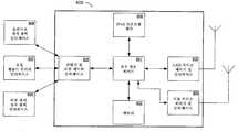
도 6은 본 발명의 일 실시예에 따른, 통신 네트워크에서 발견될 수 있는 노드의 일반 블록도.6 is a generic block diagram of a node that may be found in a communications network, in accordance with an embodiment of the present invention.
도 7은 본 발명의 일 실시예에 따른, 통신 네트워크에서 발견될 수 있는 액세스 포인트의 일반 블록도.7 is a general block diagram of an access point that may be found in a communication network, in accordance with an embodiment of the present invention.
도 8은 본 발명의 일 실시예에 따른, 통신 네트워크에서 발견될 수 있는 백 오피스 시스템(back office system)의 일반 블록도.8 is a general block diagram of a back office system that may be found in a communication network, in accordance with an embodiment of the present invention.
도 9는 하나의 가능한 실시예에 따른, 유틸리티 노드의 서브 네트워크를 나타내는 일반 블록도.9 is a generic block diagram illustrating a subnetwork of utility nodes, in accordance with one possible embodiment.
도 10은 본 발명의 일 실시예에 따른, IPv4 터널이 IPv6 LAN을 IPv6 백 오피스 시스템에 접속하는 네트워크를 나타내는 일반 블록도.10 is a general block diagram illustrating a network in which an IPv4 tunnel connects an IPv6 LAN to an IPv6 back office system, in accordance with an embodiment of the present invention.
도 11은 본 발명의 일 실시예에 따른, IPv6 LAN과 연관된 액세스 포인트와 BOS 사이의 IPv4 WAN을 통한 패킷 흐름을 나타내는 일반 블록도.11 is a generic block diagram illustrating packet flow over an IPv4 WAN between an access point associated with an IPv6 LAN and a BOS, in accordance with an embodiment of the present invention.
도 12는 하나의 가능한 실시예에 따른, IPv6 패킷들이 IPv4 WAN을 통해 전달되는 네트워크를 나타내는 일반 블록도.12 is a generic block diagram illustrating a network in which IPv6 packets are delivered over an IPv4 WAN, in accordance with one possible embodiment;
도 13은 하나의 가능한 실시예에 따른, IPv4 패킷들이 IPv6 LAN을 통해 전달되는 네트워크를 나타내는 일반 블록도.13 is a generic block diagram illustrating a network in which IPv4 packets are delivered over an IPv6 LAN, in accordance with one possible embodiment.
<발명의 요약>SUMMARY OF THE INVENTION [
본 발명은 유틸리티 네트워크에서의 IP 기반 통신을 위한 시스템 및 방법을 제공한다. 유틸리티 네트워크 내의 노드는 발견 프로세스를 통해 LAN으로부터의 출구를 제공할 수 있는 그의 이웃들 및 무선 LAN 액세스 포인트들을 식별할 수 있다. 이어서, 노드는 최저 경로 비용을 제공하는 다음-홉(next-hop) 이웃 노드들을 통한 진출을 위해 바람직한 액세스 포인트들에 대한 한 세트의 최적 라우트들을 설정한다. 노드는 등록 요청을 하나 이상의 액세스 포인트 장치로 전송할 수 있다. 하나 이상의 액세스 포인트 장치로부터 수신되는 액세스 포인트 장치의 네트워크 어드레스의 IP 네트워크 어드레스 프리픽스는 엔드 노드에 의해 유틸리티 노드에 대한 고유 네트워크 어드레스를 프로그램 방식으로 생성하는 데 사용된다. 유틸리티 노드는 DNS 서버에 등록한다. 유틸리티 노드로 전송되는 메시지들은 유틸리티 노드에 대한 네트워크 어드레스를 생성하는 데 사용된 프리픽스에 대응하는 액세스 포인트를 통해 라우팅된다. 유틸리티 노드 및 액세스 포인트에 대한 네트워크 어드레스는 IPv6 어드레스들일 수 있으며, 네트워크 어드레스 프리픽스는 IPv6 프리픽스일 수 있다.The present invention provides a system and method for IP based communication in a utility network. A node in the utility network can identify its neighbors and wireless LAN access points capable of providing an exit from the LAN through the discovery process. The node then sets a set of optimal routes for the preferred access points for entry through next-hop neighbor nodes providing the lowest path cost. A node may send a registration request to one or more access point devices. The IP network address prefix of the network address of the access point device received from the one or more access point devices is used by the end node to programmatically generate a unique network address for the utility node. The utility node registers with the DNS server. Messages sent to the utility node are routed through the access point corresponding to the prefix used to generate the network address for the utility node. The network address for the utility node and the access point may be IPv6 addresses, and the network address prefix may be an IPv6 prefix.
본 발명은 특정 실시예와 관련하여 설명된다. 이것은 본 발명의 특징들 및 원리들의 이해를 돕기 위해 행해지며, 본 발명은 이 실시예로 한정되지 않는다. 특히, 본 발명은 유틸리티 네트워크 내의 전자 장치들을 원격적으로 판독, 제어 및 관리하기 위한 시스템과 관련하여 설명된다. 본 발명은 전자 장치들 및 물자 계량기들의 네트워크 기반 관리를 위한 다른 시스템들에도 적용될 수 있다.The invention is described with reference to specific embodiments. This is done to help understand the features and principles of the present invention, and the present invention is not limited to this embodiment. In particular, the present invention is described in the context of a system for remotely reading, controlling, and managing electronic devices within a utility network. The present invention is also applicable to other systems for network-based management of electronic devices and material meters.
본 실시예는 유틸리티 네트워크에서 유틸리티 계량기를 모니터링하고 제어하는 네트워크 기반 시스템 및 방법을 제공한다.The present embodiment provides a network-based system and method for monitoring and controlling utility meters in a utility network.
도 1은 본 발명의 실시예들을 구현하는 데 사용될 수 있는 유틸리티 네트워크(100)의 일반 블록도이다. 유틸리티 네트워크(100)는 하나 이상의 전자 장치(101)를 포함할 수 있다. 바람직한 실시예에서, 전자 장치들(101)은 무선 근거리 네트워크(LAN)(102)를 통해 접속될 수 있다. 유틸리티 네트워크의 예에서, LAN은 유틸리티를 위한 이웃 또는 서비스 영역에 대응하는 이웃 영역 네트워크(NAN)일 수 있다. 실시예에 도시된 바와 같이, 오버랩되거나 오버랩되지 않을 수 있는 다수의 LAN이 사용될 수 있으며, 따라서 주어진 전자 장치는 단 하나의 무선 LAN 또는 다수의 무선 LAN에 접속될 수 있다(또는 그의 일부일 수 있다). 전자 장치들은 임의 타입의 전자 장치일 수 있다. 전자 장치들의 예는 유틸리티 계량기를 포함하거나 유틸리티 계량기에 접속할 수 있는 유틸리티 노드들을 포함한다. 유틸리티 계량기는 계량되는 양, 통상적으로는 전기, 물, 천연 가스 등과 같은 물자를 측정할 수 있는 장치이다. 유틸리티 계량기에 접속하는 유틸리티 노드들은 네트워크 상에서의 통신을 위한 네트워크 인터페이스 카드(NIC)를 포함할 수 있으며, 하나 이상의 무선 LAN과 통신하기 위한 하나 이상의 RF 송수신기를 포함할 수 있다. 전자 장치들의 다른 예는 셋톱 박스(케이블 텔레비전 또는 위성 텔레비전 전송에서 사용될 수 있음)와 같은 통신 장치, 가전 제품(예를 들어, 냉장고, 히터, 전등, 조리 기구 등), 컴퓨터 또는 컴퓨팅 장치(예를 들어, 게임 콘솔, 저장 장치, PC, 서버 등), 릴레이, 게이트웨이, 액세스 포인트, 라우터 또는 기타 네트워킹 장치들과 같은 네트워킹 장치, 전화 또는 셀 폰, 배터리 저장 장치, 운송 장치, 운송 차량(예를 들어, 전기 또는 하이브리드 카 또는 기타 차량), 엔터테인먼트 장치(예를 들어, TV, DVD 플레이어, 셋톱 박스, 게임 콘솔 등), 또는 가정, 회사, 도로 또는 주차장 또는 다른 장소에서 발견될 수 있는 다른 장치를 포함한다. 릴레이는 전자 장치(101)와 무선 LAN(102) 사이의 통신을 처리할 수 있다. 예를 들어, 릴레이는 전자 장치와 무선 네트워크의 기반구조 사이의 통신을 제공할 수 있다. 달리 지시되지 않는 한, 계량기, 전자 장치, 게이트웨이 등과 같은 네트워크 내의 다른 장치들은 릴레이의 기능을 수행할 수도 있으며, 릴레이는 네트워크 상의 다른 장치들 또는 소프트웨어의 기능들을 수행할 수도 있다.1 is a general block diagram of a
무선 LAN(102)은 임의 타입의 무선 네트워크일 수 있으며, 임의의 주파수, 통신 채널 또는 통신 프로토콜을 사용할 수 있다.The
LAN(102)은 통상적으로 하나 이상의 액세스 포인트(AP; 103)에 접속된다. 주어진 LAN은 단일 AP에만 접속될 수 있거나, 둘 이상의 액세스 포인트에 접속될 수 있다. 액세스 포인트들(103)은 하나 이상의 광역 네트워크(WAN)(104)에 접속될 수 있다. WAN들(104)은 하나 이상의 백 오피스 시스템(BOS)(105)에 접속될 수 있다. 백 오피스 시스템은 계량 정보의 수집에의 관여, 계량 장치들의 관리, 네트워크 보안, 또는 AMI 네트워크에서 요구될 수 있는 다른 기능들을 포함하는 다양한 비즈니스 또는 관리 태스크들을 처리할 수 있다. 백 오피스 시스템들의 예는 요금 청구 및 회계 시스템, 프록시 서버, 정전 검출 시스템(유틸리티 네트워크에서 사용될 수 있음), 데이터 저장 시스템 등을 포함한다.LAN 102 is typically connected to one or more access points (APs) 103. A given LAN can be connected to only a single AP or to more than one access point.
LAN 또는 WAN, 또는 이들의 조합일 수 있는 통신 네트워크 내의 노드들은 하나 이상의 프로토콜을 이용하여 통신할 수 있다. 노드들은 전자 장치, 릴레이, 액세스 포인트, 라우터 또는 BOS를 포함할 수 있다. 일부 노드들은 IPv6를 이용하여 통신할 수 있고, 일부 노드들은 IPv4를 통해 통신할 수 있으며, 일부 노드들은 IPv4 또는 IPv6을 통해 통신할 수 있다. 일부 노드들은 IPv4 패킷 내에 IPv6 패킷들을 캡슐화할 수 있다. 또한, 일부 노드들은 IPv6 네트워크를 통해 IPv4 터널을 설정할 수 있다. 노드들 사이의 통신은 아래 더 상세히 설명된다.Nodes in a communication network, which may be a LAN or a WAN, or a combination thereof, may communicate using one or more protocols. The nodes may include electronic devices, relays, access points, routers or BOS. Some nodes can communicate using IPv6, some nodes can communicate over IPv4, and some nodes can communicate over IPv4 or IPv6. Some nodes may encapsulate IPv6 packets in an IPv4 packet. In addition, some nodes may establish an IPv4 tunnel over an IPv6 network. The communication between the nodes is described in more detail below.
통신 네트워크에서의 네트워크 어드레스의 할당 및 등록Assignment and registration of network addresses in a communication network
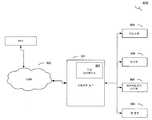
도 2는 LAN(200) 및 LAN(206)을 포함하는 통신 네트워크의 일반 블록도이다. LAN들은 노드들(202)과 액세스 포인트들(201)을 접속한다. 도시된 바와 같이, LAN(200)은 2개의 액세스 포인트를 가지며, LAN(206)은 하나의 액세스 포인트를 갖는다. 도메인 네임 서버(DNS)(203)가 통신 네트워크(204)에 대한 액세스 포인트(201)를 통해 LAN(200) 및 LAN(206)에 접속된다. 현재 바람직한 실시예에서, DNS 서버(203)는 동적 갱신들을 수신하고 처리할 수 있으며, 따라서 동적 DNS 서비스를 제공할 수 있다. DNS의 동적 갱신은 IETF RFC 2136에 따라 수행된다. 통신 네트워크(204)는 LAN, WAN, 무선, 고정 라인, 사설 네트워크, 가상 사설 네트워크 등을 포함하지만 이에 한정되지 않는 임의 타입의 통신 네트워크일 수 있다. 현재 바람직한 실시예에서, 통신 네트워크(204)는 광역 네트워크이며, IPv4 또는 IPv6과 같은 하나 이상의 통신 프로토콜을 사용할 수 있다. 하나 이상의 컴퓨팅 장치(205)가 통신 네트워크(204)에 접속한다. 컴퓨팅 장치(205)에서 노드(202)로의 메시지는 노드에 대한 네트워크 어드레스를 이용하여 전송될 수 있다. 컴퓨팅 장치(205)는 통신 네트워크(204)를 통해 액세스 포인트 또는 노드와 통신할 수 있는 임의의 장치, 장치들의 조합, 네트워크 관리 시스템, 서버, 백 오피스 시스템(B0S), 컴퓨터, 네트워크 장치, 통신 장치, 소프트웨어 애플리케이션 또는 컴포넌트일 수 있다. 제2 LAN(206)도 DNS 서버(203) 및 통신 네트워크(204)에 접속될 수 있다. DNS 서버는 단일 LAN에 전용화되거나, 둘 이상의 LAN이 DNS 서버를 공유할 수 있다. 도시된 바와 같이, LAN(200) 및 LAN(206)은 도시된 노드들 중 어느 것도 그리고 액세스 포인트들 중 어느 것도 LAN(200) 및 LAN(206) 양자의 멤버가 아니라는 점에서 오버랩되지 않는다. 대안 실시예들은 오버랩되는 하나 이상의 LAN을 가질 수 있는데, 이 경우에는 하나 이상의 노드 및/또는 액세스 포인트가 하나 이상의 LAN에 공통이 된다. 대안 실시예들은 서로 오버랩되거나 오버랩되지 않을 수 있는 추가 LAN들을 가질 수 있다. 현재 바람직한 실시예에서, 노드의 네트워크 어드레스는 아래의 도 3과 관련하여 설명되는 프로세스에 따라 얻어진다.2 is a general block diagram of a communication
DNS 서버(203)는 그와 연관된 LAN 네트워크의 노드들에 대한 네트워크 어드레스들을 유지한다. 전술한 바와 같이, DNS 서버는 하나 이상의 LAN과 연관될 수 있으며, 하나 이상의 LAN 내의 노드들의 네트워크 어드레스들을 유지할 수 있다. 하나의 바람직한 실시예에서, 여러 액세스 포인트에 등록된 노드는 적어도 그와 동일한 수의 네트워크 어드레스를 가질 수 있다. 노드들에 대한 네트워크 어드레스들은 DNS 서버 또는 노드 라우트 레지스트리 내에 포함될 수 있다. 또한, DNS 서버는 노드 어드레스 할당 지시자(또는 노드 선호 지시자)와 같은 어드레스 할당 정보를 유지할 수도 있다. 아래의 테이블 1은 LAN 내의 노드들에 대한 네트워크 어드레스들의 유지에 포함될 수 있는 정보의 일부를 나타낸다. DNS 서버 내에 유지되는 자원 레코드들은 다음을 포함할 수 있다.
테이블 1Table 1
ADDR2
ADDR3ADDR1
ADDR2
30
1050
30
10
ADDR6ADDR5
ADDR6
2044
20
테이블 1에 나타난 바와 같이, 현재 바람직한 실시예에서, 노드 이름은 노드의 MAC 어드레스이다. 그러나, 다른 실시예들은 MAC 어드레스를 포함하거나 포함하지 않을 수 있거나 MAC 어드레스에 기초하거나 기초하지 않을 수 있는 노드에 대한 다른 이름들을 사용할 수 있다. 또한, 테이블 1의 자원 레코드(RR) 타입은 IPv6 타입일 수 있다.As shown in Table 1, in the presently preferred embodiment, the node name is the MAC address of the node. However, other embodiments may use other names for nodes that may or may not include a MAC address, or may or may not be based on a MAC address. Also, the resource record (RR) type of Table 1 may be an IPv6 type.
라우트 레지스트리 내의 정보는 주기적인 방식 또는 하나 이상의 기준이 만족되는 경우를 포함하는 다양한 기준에 따라 갱신될 수 있다.The information in the route registry may be updated in accordance with various criteria, including in a periodic manner or when one or more criteria are met.
설명의 목적으로, 하나의 DNS 서버만이 도시되고, 아래에 설명된다. 그러나, 대안 실시예들은 다수의 DNS 서버를 사용할 수 있다.For purposes of explanation, only one DNS server is shown and described below. However, alternative embodiments may use multiple DNS servers.
DNS 자원 레코드들의 대안 실시예들은 추가 정보를 포함하거나, 테이블 1에 포함된 정보의 일부를 배제할 수 있다. 또한, 테이블 1은 단지 3개의 노드에 대한 정보를 포함하지만, 라우트 레지스트리의 대안 실시예들은 더 많거나 적은 노드에 관한 정보를 가질 수 있다. 테이블 1은 주어진 노드에 대해 최대 3개의 네트워크 어드레스를 포함하지만, 라우트 레지스트리의 대안 실시예들은 노드당 임의 수의 어드레스를 가질 수 있다.Alternative embodiments of DNS resource records may include additional information or may exclude some of the information contained in Table 1. In addition, although Table 1 contains information for only three nodes, alternative embodiments of the route registry may have more or less information about the node. Table 1 includes a maximum of three network addresses for a given node, but alternative embodiments of the route registry may have any number of addresses per node.
도 3은 노드의 네트워크 어드레스를 얻기 위한 프로세스(300)의 일반 흐름도이다. 단계 301에서, 패킷 또는 메시지를 노드로 전송하고자 하는 노드는 DNS 서버에게 DNS 해결을 요청한다. DNS 해결 요청은 노드 식별자, 통상적으로는 노드 이름을 포함한다. 노드 식별자는 글자들, 번호들, 심벌들 또는 문자들의 임의 조합일 수 있다. 테이블 1과 관련하여 전술한 바와 같이, 현재 바람직한 일 실시예에서, 노드 식별자는 의도하는 노드의 MAC 어드레스이다. 테이블 1에 나타난 바와 같이, 소스 또는 요청 노드는 노드의 식별자, 노드의 네트워크 어드레스, 네트워크 어드레스 선호 등을 특정하는 정보를 포함한다. 단계 302에서, DNS 서버는 의도하는 노드에 대한 DNS 해결 요청을 수신한다. 단계 303에서, DNS 서버는 노드 식별자와 연관된 노드에 대한 네트워크 어드레스로 응답한다. 현재 바람직한 실시예에서, 네트워크 어드레스는 IP 어드레스이다. 현재 바람직한 일 실시예에서, 자원 레코드 AAAA는 IPv6 어드레스와 관련된다. IPv4 자원 레코드(RR)는 A, PTR, CNAME 타입일 수 있다. DNS 서버는 주어진 노드에 대한 둘 이상의 네트워크 어드레스를 가질 수 있다. 예를 들어, 다수의 IPv6 어드레스가 주어진 노드(또는 액세스 포인트, 또는 BOS, 또는 네트워크 상의 임의의 다른 장치)와 연관될 수 있다. 다수의 어드레스가 주어진 노드와 연관되는 경우, 단계 302에서 DNS 서버는 특정 RR에 대한 모든 이용 가능한 네트워크 어드레스를 제공할 수 있다. 대안으로, DNS 서버는 의도하는 노드와 연관된 네트워크 어드레스들의 서브세트를 선택할 수 있다. 예를 들어, DNS 서버는 전자 장치에 응답하여 포함할 하나의 네트워크 어드레스를 선택할 수 있다. 의도하는 노드와 연관된 네트워크 어드레스들의 서브세트가 선택되는 경우, 선택은 접속 비용, 사전 설정된 선택 기준들, 정책(예를 들어, 노드와 메시지들을 교환하기를 의도하는 전자 장치, 메시지의 타입, 크기 또는 우선 순위, 노드에 의한 메시지의 사용의 소정 양태, 또는 네트워크 장치, 예를 들어 서버, 네트워크 관리 시스템, 요금 청구 시스템, 정전 관리 시스템, 유틸리티 관리 시스템 등의 특성) 또는 소정의 다른 기준들에 기초할 수 있다. 다수의 네트워크 어드레스가 DNS 해결 응답에서 제공되는 경우, 응답은 대응하는 노드 어드레스 선호 지시자들도 포함할 수 있다. 단계 304에서, 노드는 DNS 서버로부터 DNS 해결 응답을 수신한다. 단계 305에서, 노드는 DNS 서버로부터 수신된 네트워크 어드레스를 이용하여 그의 메시지를 전송한다.3 is a general flow diagram of a
노드 및/또는 전자 장치에서 의도하는 노드 또는 전자 장치로 메시지를 전송하는 데 사용되는 어드레스는 하나 이상의 액세스 포인트에 대응할 수 있다. 예를 들어, IPv6 LAN에서, 네트워크 어드레스는 통상적으로 IPv6 어드레스일 것이다. 둘 이상의 액세스 포인트가 존재하는 경우, 네트워크 어드레스의 IPv6 프리픽스는 주어진 액세스 포인트와 연관될 수 있다. 이러한 방식으로, IPv6 네트워크 어드레스는 주어진 액세스 포인트가 메시지를 네트워크 목적지로 전송하는 것을 가능하게 할 수 있다. 노드가 다수의 액세스 포인트를 갖는 LAN 내에 있는 경우, 노드는 노드와 연관된 둘 이상의 IPv6 어드레스를 가질 수 있다.An address used to transmit a message to a node or an electronic device intended for the node and / or the electronic device may correspond to one or more access points. For example, in an IPv6 LAN, the network address will typically be an IPv6 address. If more than one access point is present, the IPv6 prefix of the network address may be associated with a given access point. In this manner, the IPv6 network address may enable a given access point to send a message to a network destination. If the node is in a LAN with multiple access points, the node may have more than one IPv6 address associated with the node.
예 1 - IPv6 네트워크 어드레싱을 이용하는 다중 진입Example 1 - Multiple ingress using IPv6 network addressing
본 예는 노드1의 노드 이름을 갖는 주어진 노드를 갖는다. 노드1은 그와 연관된 2개의 IPv6 네트워크 어드레스를 갖는다. 노드1에 대한 라우트 레지스트리 엔트리는 다음과 같다.This example has a given node with the node name of
DDNS 라우트 레지스트리DDNS Route Registry
2001:2105:20ae:2:225:3400:208:aa032001: 2105: 20ae: 1: 225: 3400: 208: aa03
2001: 2105: 20ae: 2: 225: 3400: 208:
3050
30
노드1은 2개의 액세스 포인트(AP1, AP2)를 통해 통신 네트워크에 접속한다. AP1은 IPv6 프리픽스 2001:2105:20ae:1::/64와 연관되고, AP2는 IPv6 프리픽스 2001:2105:20ae:2::/64와 연관된다.
메시지를 노드1로 전송하려고 의도하는 네트워크 장치, 예를 들어 정전 검출을 관리하는 백 오피스 시스템은 DNS 서버의 라우트 레지스트리로부터 노드1과 연관된 네트워크 어드레스를 수신할 수 있다(또는 양 네트워크 어드레스를 수신할 수 있다). 프리픽스 2001:2105:20ae:2::/64를 갖는 네트워크 어드레스를 이용하여 정전 검출 시스템에서 노드1로 전송되는 메시지는 AP2를 통해 라우팅될 것이다. 프리픽스 2001:2105:20ae:1::/64를 갖는 네트워크 어드레스를 이용하여 정전 검출 시스템에서 노드1로 전송되는 메시지는 AP1을 통해 라우팅될 것이다.A network device that intends to send a message to
도 4는 노드 장치를 액세스 포인트에 등록하기 위한 프로세스(400)를 나타내는 일반화된 통신 흐름도이다. 네트워크 어드레스를 얻기 위해 노드 장치를 등록하는 것은 임의 포맷 또는 프로토콜의 네트워크 어드레스들에 적용될 수 있다. 하나의 현재 바람직한 실시예에서, LAN은 IPv6 프로토콜들을 (독점적으로 또는 IPv4 프로토콜들과 병행하여) 이용할 수 있다. 설명의 목적으로, 프로세스(400)는 IPv6 네트워크 어드레스들을 이용하는 무선 LAN의 노드들을 기술할 것이다. 현재 바람직한 실시예에서, 노드 M은 발견 프로세스를 개시하고, 출구 및 입구를 제공하는 그의 이웃 노드들 및 하나 이상의 LAN의 액세스 포인트들을 식별한다. 노드 M은 라우팅 분석을 더 개시하여, 하나 이상의 액세스 포인트를 통해 최저 경로 비용으로 출구를 제공하는 1-홉(one-hop) 이웃들의 바람직한 세트를 식별할 수 있다. 이어서, 노드 M은 하나 이상의 AP 및 가입된 DNS 서버들에 대한 등록 프로세스를 개시할 수 있다. 401에서, 노드 M은 계층 2 등록 메시지를 액세스 포인트(AP)로 전송한다. 402에서, AP는 AP와 연관된 IPv6 프리픽스를 포함하는 계층 2 수신 확인 메시지로 응답한다. 또한, 수신 확인 메시지는 구성 정보를 포함할 수 있다. 현재 바람직한 실시예에서, 구성 정보는 노드 M이 DNS 서버에 등록하는 것을 허가하는 정보를 포함한다. 다른 실시예에서, AP는 노드 M을 대신하여 DNS 요청을 프록시할 수 있다. 403에서, 노드 M은 계층 2 수신 확인 메시지를 수신하고, 계층 3 IPv6 등록 메시지를 DNS로 전송한다. 하나의 현재 바람직한 실시예에서, DNS에 대한 IPv6 등록 메시지는 노드 M에 대한 IPv6 어드레스를 포함하며, 노드 M는 노드 M에 대한 IPv6 어드레스를 완성하기 위해 AP로부터 수신된 IPv6 프리픽스 및 고유 IPv6 "서픽스"를 사용한다. 이것은 RFC 2462의 무상태(stateless) 자동 구성 단계들과 일관되게 수행된다. 하나의 바람직한 실시예에서, IPv6 서픽스는 노드 M의 MAC 어드레스에 기초한다. 대안 실시예들은 MAC 어드레스에 기초하지 않는 다른 서픽스들을 이용하여, 노드 M에 대한 고유 IPv6 어드레스를 생성할 수 있다. 노드 M에 대한 IPv6 어드레스는 전역적으로 고유할 필요는 없다는 점에 유의한다.4 is a generalized communication flow diagram illustrating a
404에서, 계층 3 수신 확인 메시지가 DNS에서 노드 M으로 전송되고, 405에서 노드 M에 의해 수신된다. 계층 3 수신 확인 메시지는 노드 M의 DNS 서버에 대한 등록의 등록 확인을 포함할 수 있으며, 추가 정보를 포함할 수 있다.At 404, a
프로세스(400)는 하나의 노드의 하나의 액세스 포인트에 대한 등록만을 보여주지만, 현재 바람직한 실시예에서는 모든 노드가 적어도 하나의 액세스 포인트에 등록할 것이다. 또한, 하나의 현재 바람직한 실시예에서, 노드들은 노드와 연관된 LAN 상에 둘 이상의 액세스 포인트가 존재하는 경우에 그들의 LAN 상의 둘 이상의 액세스 포인트에 등록할 것이다. 노드는 노드와 연관된 LAN 상의 모든 액세스 포인트에 등록할 수도 있다.Although
현재 바람직한 실시예에서, 주어진 노드는 노드와 연관된 둘 이상의 고유 IPv6 어드레스를 가질 수 있다. 전술한 바와 같이, 노드의 IPv6 어드레스가 액세스 포인트의 IPv6 프리픽스 및 고유 성분(예를 들어, 노드의 MAC 어드레스)로부터 결정되는 경우에, 노드가 다수의 어드레스 포인트에 등록하는 경우에는, 노드는 다수의 고유 IPv6 어드레스와 연관될 것이다. 이러한 방식으로, 노드들은 멀티홈(multihome)을 가질 수 있다.In the presently preferred embodiment, a given node may have more than one unique IPv6 address associated with the node. As described above, in the case where the node's IPv6 address is determined from the IPv6 prefix and unique component (e.g., node's MAC address) of the access point, the node registers with multiple address points, Will be associated with a unique IPv6 address. In this way, the nodes may have a multihome.
노드 M은 406에서 3 SNMP TRAP 또는 INFORM 메시지를 백 오피스 시스템(BOS)으로 전송할 수 있다. 대안으로, DNS 서버는 SNMP를 통해 BOS에 시그널링할 수 있다. 바람직하게는, SNMP 또는 INFORM 메시지는 노드 M의 적어도 하나의 IPv6 어드레스를 포함할 수 있다(그리고 노드 M과 연관된 다수의 네트워크 어드레스를 포함할 수 있다). 407에서, BOS는 SNMP TRAP 또는 INFORM 메시지를 수신하고, GMI(Generic Management Interface) 데이터 조회와 같은 계층 3 메시지로 응답한다. GMI 데이터 조회 메시지는 노드 M에 관한 정보를 요청할 수 있다. 예를 들어, 노드 M이 유틸리티 네트워크 내의 계량기(meter)인 경우, GMI 데이터 조회 메시지는 계량기의 구성 설정들에 관한 정보, 계량기의 상태, 계량된 물자에 관한 정보 등을 요청할 수 있다. 408에서, 노드 M은 데이터 조회 메시지를 수신하고, 데이터 응답 메시지를 전송한다. 409에서, BOS는 노드 M으로부터 데이터 응답 메시지를 수신한다.Node M may send 3 SNMP TRAP or INFORM messages to the back office system (BOS) at 406. Alternatively, the DNS server can signal to the BOS via SNMP. Preferably, the SNMP or INFORM message may include at least one IPv6 address of node M (and may include multiple network addresses associated with node M). At 407, the BOS receives an SNMP TRAP or INFORM message and responds with a
BOS는 임의 시간에 주어진 노드의 네트워크 어드레스를 요청할 수 있다. 예를 들어, BOS가 메시지를 기대한 때 노드 M으로부터 메시지를 수신하지 못한 경우, BOS는 노드 M에 조회할 수 있다. BOS가 노드 M의 네트워크 어드레스를 아직 갖지 못한 경우, 또는 하나의 현재 바람직한 실시예에서와 같이, BOS가 수신된 메시지에 응답하고 있지 않은 경우에 네트워크가 네트워크 어드레스를 요청하도록 구성되는 경우에는, BOS는 DNS 서버에 대한 탐색(즉, DNS 해결 요청)을 수행할 수 있다. 410에서, BOS는 노드 M에 대한 IPv6 네트워크 어드레스 탐색 메시지를 DNS 서버로 전송한다. 411에서, DNS 서버는 노드 M에 대한 IPv6 어드레스로 BOS에 응답한다(DNS 서버가 노드 M에 대한 네트워크 어드레스를 갖지 않은 경우, DNS 서버는 그가 노드 M에 대한 네트워크 어드레스를 갖지 않는다는 것을 응답할 수 있다). 412에서, 노드 M에 대한 IPv6 어드레스가 수신된다.The BOS can request the network address of a given node at any time. For example, if a BOS does not receive a message from node M when it expects a message, the BOS can query node M. If the BOS is not yet having a network address of node M, or if the network is configured to request a network address in case the BOS is not responding to the received message, as in one presently preferred embodiment, (I.e. DNS resolution request) to the DNS server. At 410, the BOS sends an IPv6 network address lookup message for node M to the DNS server. At 411, the DNS server responds to the BOS with an IPv6 address for node M (if the DNS server does not have a network address for node M, the DNS server may reply that it does not have a network address for node M ). At 412, an IPv6 address for node M is received.
노드가 등록되지 않은 경우, 또는 BOS가 노드에 대한 네트워크 어드레스를 수신하지 못한 경우, BOS는 IP 어드레스를 프로그램 방식으로 도출하려고 시도하거나, IP 어드레스를 생성하려고 시도할 수 있다. (전술한 바와 같이) BOS는 AP의 IPv6 어드레스 및 노드의 MAC 어드레스를 이용하여 임시 IPv6 어드레스를 생성할 수 있다. 또한, BOS는 노드의 고유 MAC 식별자에 따라 노드에 기초하여 메시지를 노드로 전송할 것을 AP에게 요청하는 IPv6 메시지를 AP로 전송할 수 있다. 대안으로, BOS는 노드의 네트워크 어드레스를 결정하고 그리고/또는 등록 프로세스의 결과들을 조사하기 위해 노드를 핑(ping)하도록 AP에게 요청할 수 있다.If the node is not registered, or if the BOS does not receive a network address for the node, the BOS may attempt to programmatically derive the IP address or attempt to generate an IP address. The BOS (as described above) can generate a temporary IPv6 address using the IPv6 address of the AP and the MAC address of the node. In addition, the BOS may transmit an IPv6 message to the AP requesting the AP to send a message to the node based on the node according to the unique MAC identifier of the node. Alternatively, the BOS may ask the AP to determine the network address of the node and / or to ping the node to examine the results of the registration process.
노드 M이 문제, 예를 들어 전력 손실, 보안 사고, 그의 하드웨어 또는 소프트웨어의 문제, 네트워크 문제 등에 직면하는 경우, 노드 M은 SNMP TRAP 또는 INFORM 메시지와 같은, 문제를 지시하는 메시지를 BOS로(또는 노드 M에 의해 도달 가능한 임의의 장치로) 전송할 수 있다. 전력 손실의 경우, 노드 M은 "라스트 가습(last gasp)" 메시지를 전송할 수 있다. 413에서, 노드 M은 라스트 가습 메시지를 AP로 전송한다. 통상적으로, 계층 2 라스트 가습 메시지는 매우 짧고, 노드 및 네트워크의 자원들을 보존하기 위한 필수 정보만을 가지며, 따라서 메시지는 다른 이웃 노드들 및 대응 AP에 의해 신뢰성 있게 수신된다. 414에서, AP는 노드 M으로부터 라스트 가습 메시지를 수신하며, 현재 바람직한 실시예에서 SNMP TRAP 또는 INFORM PDU(Protocol Data Unit 또는 SNMP 패킷)를 L2 "라스트 가습" 메시지들과 함께 팩킹하고, 이들을 BOS로 전송하여, AP가 노드 M으로부터 라스트 가습 메시지를 수신하였음을 지시한다.If the node M encounters a problem, for example a power loss, a security incident, a problem with its hardware or software, a network problem, the node M sends a message indicating the problem, such as an SNMP TRAP or INFORM message, To any device reachable by M). In case of power loss, node M may send a "last gasp" message. At 413, node M transmits a last humidification message to the AP. Typically, the
예 2 - 운송 노드들에 대한 네트워크 어드레싱Example 2 - Network Addressing for Transport Nodes
본 예는 도 5에 도시된 바와 같은 운송 장치인 주어진 노드를 갖는다. 구체적으로, 노드 H는 그의 배터리들이 전기 그리드로부터 충전될 수 있는 하이브리드 카이다. 노드 H의 플러그를 전기 콘센트에 꽂을 때, 노드 H는 BOS-HB라고 하는 전기 유틸리티 요금 청구 BOS와 통신을 설정하려고 시도한다. 본 예에서, 노드 H는 IPv6 프로토콜을 이용하는 무선 통신 네트워크인 LAN-7의 커버리지 영역 내에 있다. 노드 H는 계층 2 등록 요청 메시지를 LAN-7 내의 적어도 하나의 액세스 포인트로 전송한다. LAN-7과의 액세스 포인트인 AP1은 4ea3인 그의 IPv6 프리픽스로 응답한다. 노드 H는 AP1로부터 수신된 프리픽스를 이용하여 고유 IPv6 어드레스를 생성한다. 노드 H는 노드 H 내의 네트워크 카드의 MAC 어드레스를 AP1로부터의 IPv6 프리픽스와 함께 이용하여 고유 IPv6 어드레스를 생성한다. 노드 H는 계층 3 등록 메시지를 LAN-7과 연관된 DNS 서버로 전송하고, DNS 서버로부터 수신 확인을 수신한다. 또한, 노드 H는 AP2라고 하는 LAN-7 상의 제2 액세스 포인트에 등록한다. AP1 및 AP2는 모두 통신 네트워크를 통해 BOS-HB와 통신할 수 있다. AP2는 21ff인 그의 IPv6 프리픽스를 노드 H로 전송하며, 노드 H는 이를 이용하여 AP2와 연관된 제2 고유 IPv6 어드레스를 생성한다. 이어서, 노드 H는 그가 LAN-7 상에 있음을 지시하는 SNMP TRAP 또는 INFORM 메시지를 BOS-HB로 전송한다. 또한, BOS-HB에 대한 메시지는 노드 H가 현재 전기 그리드에 접속되어 노드 H의 배터리들을 재충전하기 위한 전력을 수신하고 있음을 BOS-HB에게 알리기 위한 정보를 포함한다. BOS-HB는 노드 H의 전기 사용을 조사하기 위한 메시지를 노드 H로 전송하며, 또한 노드 H가 여전히 네트워크 상에 있는지를 검사하기 위한 메시지를 전송한다. 메시지를 노드 H로 전송하기 전에, BOS-HB는 DNS 서버를 이용하여 노드 H의 네트워크 어드레스의 탐색을 수행한다. DNS 서버는 노드 H에 대응하는 탐색 요청에 응답하여 노드 H와 연관된 2개의 고유 IP 어드레스 중 어느 것을 BOS-HB에 제공할 것인지를 결정할 수 있다. 이 실시예에서, DNS 서버의 라우트 레지스트리는 노드 H에 대응하는 IPv6 어드레스들과 연관된 고유 선호 지시자를 포함한다. 선호 지시자는 AP2가 AP1보다 AP2와의 보다 신뢰성 있는 접속을 가지므로 AP2가 AP1보다 선호됨을 지정한다. 따라서, DNS 서버는 AP2와 연관된 네트워크 어드레스로 B0S-HB에 응답한다. 이어서, BOS-HB는 AP2와 연관된 네트워크 어드레스를 이용하여, AP2를 통해 메시지를 노드 H로 라우팅한다. AP2를 통해 BOS-HB에서 노드 H로 메시지를 전달하는 것에 실패한 경우, BOS-HB(또는 네트워크 상의 다른 장치)는 노드 H와 연관된 다음의 가장 선호되는 네트워크 어드레스를 요청하여 수신하고, 실패한 메시지를 노드 H에 대한 다음의 가장 선호되는 네트워크 어드레스를 이용하여 재전송할 수 있다. 노드 H에 대한 다음의 가장 선호되는 네트워크 어드레스가 AP1에 대응하는 경우, 실패한 메시지의 재시도는 AP1를 통해 노드 H로 라우팅된다. AP2와 연관된 네트워크 어드레스에 대한 메시지 전달 실패에 응답하여, DNS 서버는 노드 H와 연관된 하나 이상의 네트워크 어드레스와 연관된 선호 지시자들을 변경할 수 있으며, 또한 하나 이상의 기준(예를 들어, 노드 H에 대한 근접성, AP2에 대한 의존성, 노드 H에 대한 의존성 등)에 따라 다른 노드들의 선호 지시자들을 변경할 수 있다. DDNS 레지스트리 내의 선호 지시자를 변경하기 위한 요청은 노드 H, BOS-HB, AP1, AP2 중 어느 하나로부터 개시될 수 있다.This example has a given node which is a transport device as shown in Fig. Specifically, node H is a hybrid car whose batteries can be charged from the electrical grid. When plugging a plug of node H into an electrical outlet, node H attempts to establish communication with an electrical utility billing BOS called BOS-HB. In this example, the node H is in the coverage area of LAN-7, which is a wireless communication network using the IPv6 protocol. The node H transmits a
노드 H는 AP2로부터 수신되는 BOS-HB로부터의 요청에 응답하여, 노드 H의 네트워크 어드레스를 포함하는 패킷을 전송한다. 포함된 네트워크 어드레스가 AP1의 프리픽스를 포함하는 경우, 패킷은 AP1을 통해 BOS-HB로 라우팅될 수 있으며, 따라서 네트워크 어드레스가 다수의 액세스 포인트 중에서 어느 액세스 포인트를 LAN-7로부터의 진출에 사용할지를 결정하는 것을 가능하게 한다. 노드 H는 노드 H와 연관된 다수의 네트워크 어드레스 중 어느 것을 노드 H로부터 전송되는 패킷의 헤더에 포함시킬지를 선택할 수 있다. 노드 H에 포함된 액세스 포인트 프리픽스에 기초하여 패킷들을 라우팅함으로써, LAN의 출구 포인트가 선택될 수 있으며, 이는 다중 출구 실시예들에서의 출구의 제어를 가능하게 한다.In response to a request from the BOS-HB received from the
노드 H가 하나의 장소에서 다른 장소로 이동(이는 주어진 AP, 노드 또는 LAN과의 직접 접촉 밖으로의 이동으로 이어질 수 있다)할 수 있는 이동 노드일 때, AP는 이동 노드를 등록 해지할 수 있다. 예를 들어, 이동 노드들은 사전 설정된 또는 설정 가능한 기간 동안 AP와 통신하지 않은 경우에 등록 해지될 수 있다. 추가로 또는 대안으로, 이동 노드들은 등록 해지되지 않도록 하기 위해 하나 이상의 AP에 정보를 전송할 수 있거나, AP에서의 정책들이 하나 이상의 특성들에 기초하여 주어진 이동 노드를 등록 해지하지 않기로 결정할 수 있다.The AP can unregister the mobile node when the node H is a mobile node that can move from one place to another (which may lead to movement out of direct contact with a given AP, node or LAN). For example, mobile nodes may be unregistered if they have not communicated with the AP for a predetermined or configurable period of time. Additionally or alternatively, the mobile nodes may send information to one or more APs so as not to be unregistered, or policies at the AP may decide not to register a given mobile node based on one or more characteristics.
IPv6 유틸리티 네트워크 지원 시스템 컴포넌트IPv6 utility network support system component
IPv6 어드레싱 및 프로토콜들을 이용하는 통신을 지원할 수 있는 유틸리티 네트워크들은 바람직하게는 IPv6를 이용하여 통신할 수 있는 다양한 장치를 사용할 수 있다. 현재 바람직한 실시예에서, 유틸리티 노드, 액세스 포인트 및 백 오피스 시스템과 같은 시스템 컴포넌트들은 각각의 시스템 컴포넌트에 통합된 IPv6 기능 지원을 가질 것이다. IPv6 가능 시스템 컴포넌트들의 바람직한 실시예들이 도 6, 7 및 8과 관련하여 도시되고 설명된다.Utility networks that can support IPv6 addressing and communications using protocols can preferably use various devices capable of communicating using IPv6. In the presently preferred embodiment, system components such as utility nodes, access points, and back office systems will have IPv6 feature support integrated into each system component. Preferred embodiments of IPv6 capable system components are shown and described with respect to Figures 6, 7 and 8.
도 6은 전술한 통신 네트워크(600)에서 발견될 수 있는 노드(600)의 일반 블록도이다. 바람직한 일 실시예에서, 노드(600)는 장치 정보 제어기(601), 메모리(602), LAN 라디오 제어기 및 인터페이스(603), 사설 라디오 제어기 및 인터페이스(604), 계량기 및 외부 데이터 인터페이스(605) 및 IPv6 프로토콜 제어기(609)를 포함할 수 있다. 계량기 및 외부 데이터 인터페이스(605)는 슬레이브 장치(606), 로컬 계량기 데이터 인터페이스(607) 및/또는 외부 센서 장치 출력 인터페이스에 접속할 수 있다. IPv6 프로토콜 제어기(609)는 IPv6 패킷들을 수신하고 송신할 수 있으며, 또한 필요에 따라 IPv6 터널들을 생성 또는 유지하거나, 패킷들을 캡슐화/비캡슐화할 수 있다.6 is a general block diagram of a
예시적인 노드(600)는 물자를 계량하기 위한 계량기를 포함하지 않지만, 대안 실시예들은 물자의 계량을 포함할 수 있다.The
예시적인 노드(600)는 사설 네트워크 라디오 또는 LAN 라디오와 같은 라디오를 포함하지 않지만, 노드의 대안 실시예들은 하나 이상의 라디오를 포함할 수 있다.
예시적인 노드(600)는 단일 장치로서 설명되지만, 대안 실시예들은 예시적인 노드(600)를 구현함에 있어서 다수의 컴퓨터, 전자 장치 또는 라디오를 사용할 수 있다.Although
도 7은 전술한 통신 네트워크(600)에서 발견될 수 있는 액세스 포인트(700)의 일반 블록도이다. 무선 LAN과 같은 네트워크 내의 노드들에 대한 게이트웨이로도 작용할 수 있는 액세스 포인트(700)는 액세스 포인트 정보 제어기(701), 메모리(702), WAN 인터페이스(703), 사설 무선 라디오 네트워크 제어기(704), 무선 LAN 라디오 제어기 및 인터페이스(705) 및 네트워크 ID IPv6 프로토콜 제어기(706)를 포함할 수 있다. 네트워크 ID IPv6 프로토콜 제어기(706)는 터널 브로커도 포함할 수 있거나, 터널 브로커를 사용하는 실시예들에서 터널 브로커가 라우터 및 6-인-4 포맷터(6-in-4 formatter)와 별개로 포함될 수 있다.7 is a general block diagram of an
예시적인 액세스 포인트(700)는 사설 네트워크 라디오, WAN 또는 LAN 라디오와 같은 라디오를 포함하지 않지만, 액세스 포인트의 대안 실시예들은 하나 이상의 라디오를 포함할 수 있다.
예시적인 액세스 포인트(700)는 네트워크 내의 계량기 또는 다른 장치(예를 들어, 릴레이 등)와 별개이지만, 대안 실시예들은 네트워크 내의 노드, 계량기, 릴레이 또는 임의의 다른 장치 또는 시스템의 기능을 결합할 수 있다.Although the
액세스 포인트(700)는 단일 장치로서 설명되지만, 대안 실시예들은 액세스 포인트(700)를 구현함에 있어서 다수의 컴퓨터, 전자 장치 또는 라디오를 이용할 수 있다.Although the
도 8은 전술한 통신 네트워크(500)에서 발견될 수 있는 백 오피스 시스템(800)의 일반 블록도이다. 백 오피스 시스템(800)은 통신 서버(801), 무선 사설 네트워크 통신 제어기(802), 라우터 및 6-인-4 포맷터(803), 애플리케이션 서버(804) 및 데이터베이스 서버(805)를 포함할 수 있다. 무선 사설 네트워크 통신 제어기(802)는 사설 무선 네트워크와 통신할 수 있다. 라우터 및 6-인-4 포맷터(803)는 WAN과 통신할 수 있다. 라우터 및 6-인-4 포맷터는 또한 터널 브로커를 포함할 수 있거나, 터널 브로커를 사용하는 실시예들에서 터널 브로커가 라우터 및 6-인-4 포맷터와 별개로 포함될 수 있다. WAN은 인터넷, 인트라넷, 또는 임의의 다른 타입의 광역 네트워크일 수 있다. 대안으로, 포맷터는 IPv6 캡슐화를 위한 6 투 4 포맷터(6 to 4 formatter)일 수 있다. 애플리케이션 서버는 유틸리티 네트워크에서 사용될 수 있는 임의 타입의 애플리케이션일 수 있다. 그 예는 요금 청구 애플리케이션, 회계 애플리케이션, 정전 검출 및/또는 관리 애플리케이션, 구성 및/또는 공급 애플리케이션, 프록시 서버, DNS 또는 DNS 서버와 같은 네트워크 애플리케이션, 저장, 백업 및/또는 복구 애플리케이션, 고객 인터페이스 애플리케이션(예를 들어, 고객이 노드와 연관된 양태들을 제어하거나 노드의 양태들을 제어하는 것을 가능하게 하는 인터페이스 애플리케이션), 노드 관리자, 콘텐츠 관리 또는 전달 시스템, 통신 관리자 또는 통신 제공 애플리케이션 등을 포함하지만, 이에 한정되지 않는다.8 is a general block diagram of a
백 오피스 시스템(800)이 단일 엔티티로서 설명되지만, 이는 하나 이상의 컴퓨터 상에서, 예를 들어 데이터 센터 내의 다수의 서버 상에서 구현될 수도 있다. 설명되는 백 오피스 시스템(800)의 컴포넌트들은 상이한 컴퓨터들 상에서 구현되거나, 다수의 컴퓨터에 걸쳐 구현될 수 있다. 또한, 백 오피스 시스템(800)은 다수의 위치 내의 또는 다수의 네트워크 상의 다수의 컴퓨터에 걸쳐 구현될 수 있다. 백 오피스 시스템(800)은 또한 다수의 애플리케이션을 결합하거나 포함할 수 있다. 예를 들어, 백 오피스 시스템은 회계 시스템은 물론, 고객 요금 청구 시스템을 포함할 수 있다. 다른 예로서, 백 오피스 시스템은 요금 청구 시스템 및 프록시 서버를 포함할 수 있다. 임의 수의 애플리케이션들의 추가 결합은 추가 대안 실시예들에 포함될 수 있다.Although the back-
유틸리티 노드 서브네트워크Utility node subnetwork
도 9는 유틸리티 노드 서브네트워크(900)를 나타내는 일반 블록도이다. 네트워크(900)는 유틸리티 노드(901)를 포함할 수 있다. 유틸리티 노드는 물자 계량기를 포함하거나, 물자 계량기와 인터페이스할 수 있다. 유틸리티 노드(901)는 통신 네트워크(902)와 통신할 수 있다. 바람직한 일 실시예에서, 유틸리티 노드(901)는 IP 프로토콜들(IPv4 또는 IPv6)을 이용하여 무선 LAN과 통신할 수 있는 무선 라디오를 포함한다. 또한, 유틸리티 노드(901)는 구내 장치 인터페이스(903)를 포함한다. 구내 장치 인터페이스(903)는 구내 장치들(904)에 접속하여 유틸리티 노드와 구내 장치들 간의 통신 링크를 제공한다. 또한, 유틸리티 노드는 구내 장치들(904)과 유틸리티 노드에 접속된 통신 네트워크(902) 사이의 통신 링크를 제공할 수 있다.FIG. 9 is a general block diagram illustrating a
현재 바람직한 일 실시예에서, 유틸리티 노드 구내 장치 인터페이스(903)는 그가 통신할 수 있는 네트워크 어드레스를 구내 장치들에 할당한다. 하나의 가능한 실시예에서, 구내 장치 인터페이스(903)에 의해 할당된 네트워크 어드레스는 IP 어드레스이다. 바람직하게는, 구내 장치에 할당된 네트워크 어드레스는 통신 네트워크(902) 내에서 고유하다. 구내 장치 인터페이스(903)는 또한 구내의 서브네트 밖의 구내 장치에 할당된 네트워크 어드레스를 공유하거나 공유를 허가할 수 있다. 따라서, 구내 장치들은 구내의 서브네트워크 외부로부터 직접 어드레스 가능하다. 유틸리티 노드는 대응하는 구내 장치를 대신하여 할당된 IP 어드레스를 프록시하며, 이에 따라 통신 네트워크 내의 다른 노드들이 할당된 IP 어드레스를 이용하여 구내 장치와 통신하는 것을 가능하게 한다. 예 3은 하나의 가능한 실시예를 통해 이를 설명한다.In one presently preferred embodiment, the utility node
예 3 - IPv6 네트워크 어드레싱을 이용한 구내 통신Example 3 - Intra-premises communication using IPv6 network addressing
본 예는 노드 31 시더 에이비(Cedar Ave)라는 노드 이름을 갖는 유틸리티 노드에 대한 것이다. 노드 31 시더 에이비는 거주 유닛(홈) 내에 배치되며, 다수의 프로토콜 및 통신 기술들을 통해 구내 장치들(홈 내의 장치들)과 통신할 수 있다. 예컨대, 유틸리티 노드 31 시더 에이비는 무선 개인 영역 네트워크(WPAN)을 이용하여 또는 홈의 전력 그리드에 접속된 PLC(Power line Carrier) 가능 장치들과의 PLC 통신을 이용하여 장치들과 통신할 수 있다. 예시적인 홈은 4개의 구내 장치, 즉 WPAN을 통해 통신하는 서모스탯, WPAN을 통해 통신하는 풀 펌프, PLC를 통해 통신하는 프리저, 및 WPAN을 통해 통신하는 홈 엔터테인먼트 시스템을 포함한다.This example is for a utility node having a node name of node 31 Cedar Ave. The Node 31 seeder address is placed in a dwelling unit (home) and is capable of communicating with intra-campus devices (devices in the home) through a number of protocols and communication technologies. For example, the utility node 31 can communicate with devices using PLC communication with PLC (Power line Carrier) capable devices using a wireless personal area network (WPAN) or connected to the power grid of the home . Exemplary grooves include four on-premises devices: a thermostat communicating via a WPAN, a full pump communicating via a WPAN, a freezer communicating via a PLC, and a home entertainment system communicating via a WPAN.
WPAN은 블루투스, 지그비(IEEE 802.15.4), IrDA, UWB(IEEE 802.15.3) 더스트 TSMP, 인스테온, IEEE 802.15에 기초하는 다른 기술 등을 포함하지만 이에 한정되지 않는 네트워크 기술들 또는 표준들 중 어느 하나 또는 임의 조합일 수 있다.The WPAN may be any of the network technologies or standards including but not limited to Bluetooth, Zigbee (IEEE 802.15.4), IrDA, UWB (IEEE 802.15.3) Dust TSMP, Or any combination thereof.
유틸리티 노드 31 시더 에이비는 IPv6 통신 프로토콜들을 이용하여 유틸리티 네트워크와 무선 통신한다. 유틸리티 네트워크는 다른 유틸리티 노드들 및 적어도 하나의 액세스 포인트는 물론, 노드 31 시더 에이비를 관리하기 위한 BOS를 포함한다.The utility node 31 Coders ABIE communicates wirelessly with the utility network using IPv6 communication protocols. The utility network includes other utility nodes and at least one access point, as well as a BOS for managing the Node 31 seeder ratio.
유틸리티 노드 31 시더 에이비는 홈의 전기 사용을 모니터링하고 보고하는 전기 사용 계량기를 포함한다. 또한, 노드 31 시더 에이비는 홈의 천연 가스 사용을 모니터링하고 보고하는 천연 가스 계량기에 접속되는 다른 물자 계량기들에 대한 인터페이스를 포함한다.The utility node 31 CedarAVI includes an electrical meter used to monitor and report electrical usage of the groove. In addition, the Node 31 Cedar Abi includes an interface to other material meters connected to the natural gas meter to monitor and report the natural gas usage of the grooves.
노드 31 시더 에이비는 그러한 구내 장치들 각각에 IPv6 어드레스를 할당한다. 노드 31 시더 에이비는 서모스탯, 풀 펌프, 프리저 및 엔터테인먼트 시스템에 대해 할당된 IPv6 어드레스를 통신 네트워크와 공유한다. 특히, 구내 장치들의 네트워크 어드레스들은 유틸리티 네트워크에 접속되고 홈 소유자가 구내 장치들을 모니터링하고 제어하는 것을 허가하는 구내 관리 포탈과 공유된다. 또한, 하나 이상의 구내 장치의 네트워크 어드레스들은 통신 네트워크 내의 노드 31 시더 에이비에 의해 프록시되거나, 통신 네트워크를 통해 노드 31 시더 에이비와 통신할 수 있다.The Node 31 seeder allocates an IPv6 address to each of such intra-node devices. The Node 31 seeder avi shares the IPv6 address assigned to the thermostat, pull pump, freezer and entertainment system with the communication network. In particular, the network addresses of the premises devices are shared with the on-premises management portal, which is connected to the utility network and which allows the homeowner to monitor and control premises devices. In addition, the network addresses of the one or more local devices may be proxied by the node 31 seeder avail- ability within the communication network, or may communicate with the node 31 seeder api via the communication network.
구내 관리 포탈을 통해, 홈 소유자(또는 다른 사람들)는 할당된 IP 어드레스를 이용하여 구내 장치들과 통신할 수 있다. 노드 31 시더 에이비는 구내 장치들을 목표로 하는 패킷들을 수신하고, 할당된 IP 어드레스에 따라 의도하는 장치를 식별하고, 적절한 구내 통신 시스템(WPAN, PLC 등)을 통해 패킷들의 페이로드를 의도하는 장치로 전송한다. 마찬가지로, 구내 통신 시스템을 통해 수신된 구내 장치로부터의 통신 신호들은 패킷(들)의 페이로드 내에 입력되고, 구내 장치에 할당된 네트워크 어드레스를 포함하는 구내 관리 포탈로 전송된다.Through the on-premises management portal, the home owner (or others) can communicate with the on-premises devices using the assigned IP address. The node 31 seeder avi is a device that receives packets destined for intra-premises devices, identifies the intended device according to the assigned IP address, and intends a payload of packets via an appropriate intra-area communication system (WPAN, PLC, etc.) Lt; / RTI > Likewise, communication signals from the intra-premises device received via the intra-premises communication system are entered into the payload of the packet (s) and forwarded to the premises management portal containing the network address assigned to the premises device.
구내 장치들에 대한 구내 레지스트리 엔트리는 다음과 같다.The local registry entries for the on-premises devices are:
구내 레지스트리Local Registry
노드 31 시더 에이비는 할당된 네트워크 어드레스들 및 구내 통신 기술을 이용하여, 구내 장치들과 구내 통신 네트워크 외부와의 통신을 허가한다.The node 31 seeder aviates communication with the premises devices and outside the on-premises communication network using the assigned network addresses and the premises communication technology.
하나의 바람직한 실시예에서, 유틸리티 노드는 또한 구내 장치들에 대한 액세스 제어 리스트(ACL)를 유지할 수 있다. 유틸리티 노드는 ACL을 이용하여 ACL에 따라 구내 장치에 대한 액세스를 허가한다. 예를 들어, ACL은 홈 보안 시스템이 보안 포탈로부터의 액세스만을 허가할 수 있는 것으로 지정할 수 있다. 홈 보안 시스템과 통신하려고 시도하는 임의의 장치 또는 시스템은 보안 포탈에 대응하는 바와 같은 ACL 내에 지정된 적절한 검증 정보를 제공하지 않으면 액세스가 거부될 것이다.In one preferred embodiment, the utility node may also maintain an access control list (ACL) for intra-premises devices. The utility node uses ACLs to grant access to the on-premises device according to the ACL. For example, the ACL can specify that the home security system can only grant access from the secure portal. Any device or system attempting to communicate with the home security system will be denied access unless it provides the appropriate validation information specified in the ACL as corresponding to the secure portal.
유틸리티 노드 ACL은 또한 착신 및 발신 트래픽 중 하나 또는 양자에 대해 허용 가능한 서비스 포트들 또는 네트워크 데몬(daemon) 이름들을 지정할 수 있다.Utility node ACLs may also specify acceptable service ports or network daemon names for one or both of incoming and outgoing traffic.
현재 바람직한 일 실시예에서, 유틸리티 노드는 구내 장치들에 대해 라우팅 가능한 네트워크 어드레스들을 할당할 수 있다. 구내 장치들은 위의 예 3에서와 같이 네트워크 어드레스를 사용하지 못할 수 있으며, WPAN 및 PLC 장치들은 그들 자신의 네트워크 어드레스를 이용하여 IP 어드레스를 할당한다. 따라서, 구내 장치에 할당되는 네트워크 어드레스는 유틸리티 노드에 의해 프록시된다. IPv6를 사용하는 실시예들에서, 액세스 포인트는 그의 할당된 IPv6 어드레스들 중 일부를 유틸리티 노드에 할당할 수 있다. 이어서, 유틸리티 노드는 유틸리티 노드에 할당된 IPv6 어드레스들로부터 어드레스들을 구내 장치들에 할당할 수 있다. 하나의 바람직한 실시예에서, AP는 하나 이상의 유틸리티 노드에 연속 어드레스들의 블록을 할당할 수 있다. 이어서, 유틸리티 노드는 할당된 어드레스들 중 임의의 어드레스 또는 그들의 부분들을 구내 장치들에 할당할 수 있다.In one presently preferred embodiment, the utility node may assign routable network addresses to intra-premises devices. Peripheral devices may not be able to use the network address as in Example 3 above, and WPAN and PLC devices use their own network address to assign an IP address. Thus, the network address assigned to the intra-premises device is proxied by the utility node. In embodiments using IPv6, an access point may assign some of its assigned IPv6 addresses to a utility node. The utility node may then assign addresses to the premises from the IPv6 addresses assigned to the utility node. In one preferred embodiment, the AP may allocate blocks of contiguous addresses to one or more utility nodes. The utility node may then assign any of the assigned addresses or portions thereof to the premises devices.
장치에 할당된 네트워크 어드레스는 장치와 통신하는 유틸리티 노드, 액세스 포인트 또는 장치 자체의 MAC 어드레스에 부분적으로 또는 전체적으로 기초할 수 있다.The network address assigned to the device may be based in part or in whole on the MAC address of the utility node, the access point, or the device itself in communication with the device.
추가로 또는 대안으로, 규칙들 및 정책들을 이용하여, 구내 장치들에 대한 어드레스들의 할당을 결정할 수 있다. 규칙들은 장치 타입, 장치 속성들, 장치에 의해 사용되는 네트워크 기술 또는 네트워크 프로토콜, 장치의 물자 사용 타입(예컨대, 전기, 가스, 물 등), 장치의 물자 사용 이력 또는 특성(예를 들어, 많은 사용, 보통 사용 등), 장치가 물리적으로 위치하는 구내 또는 구내의 부분, 또는 장치의 할당된 속성들(예를 들어, 장치의 중요성, 의료 장비, 화제 진압 장비, 보안 장비, 비상 응답 장치와 같은 장치의 용도 등)에 기초하거나, 장치의 사용자 또는 구내의 소유자/운영자에 의해 할당된 속성들에 기초할 수 있다. 또한, 규칙들은 예를 들어 장치의 타입, 물리적 구내, 전력 소비, 및 장치가 보안 또는 비상 응답과 관련되어 있는지의 여부를 고려하여 전술한 다양한 팩터들을 결합할 수 있다.Additionally or alternatively, rules and policies may be used to determine the allocation of addresses for intra-premises devices. The rules may include device type, device attributes, network technology or network protocol used by the device, material usage type of the device (e.g., electricity, gas, water, etc.), material usage history or characteristics of the device (Eg, the importance of the device, the medical device, the subject matter suppressor device, the security device, the emergency response device, etc.) of the device, Or the like), or based on attributes assigned by the user or owner / operator of the device. In addition, the rules may combine the various factors described above, for example, taking into account the type of device, physical premises, power consumption, and whether the device is associated with a security or emergency response.
추가로 또는 대안으로, 일부 네트워크 어드레스들은 특정 장치들, 용도들, 사용자들 등을 위해 보류될 수 있다. 예를 들어, 소정의 네트워크 어드레스들은 비상 인력 또는 그들의 장비를 위해 보류될 수 있다. 따라서, 주어진 구내 서브네트 상에 나타나는 비상 응답자의 이동 구내 장치는 비상 응답자들의 그러한 장치들을 위해 보류된 어드레스들의 그룹으로부터 어드레스를 할당받을 수 있다. 보류된 어드레스 그룹으로부터 주어지는 어드레스는 예를 들어 응답자의 타입(보안, 화재, EMT 등), 그들의 연합 또는 조직(부서, 관할 구역 등), 장치 타입, 또는 조직, 목적, 장치 등의 임의의 다른 속성들에 기초하여 어드레스를 할당하는 규칙에 따라 할당될 수도 있다.Additionally or alternatively, some network addresses may be reserved for specific devices, uses, users, and the like. For example, certain network addresses may be reserved for emergency personnel or their equipment. Thus, a mobile intranet of an emergency responder appearing on a given intra-city subnet may be assigned an address from a group of addresses reserved for such devices of the emergency responders. The address given from the group of pending addresses may be, for example, the type of respondent (security, fire, EMT, etc.), their association or organization (department, jurisdiction, etc.), device type, or any other attribute Or may be allocated according to a rule for assigning an address based on the addresses.
예 4는 유틸리티 노드들에 대한 어드레스들의 할당 및 유틸리티 노드들을 이용하는 구내 장치들에 대한 할당된 어드레스들의 할당을 구현하기 위한 하나의 가능한 실시예를 나타낸다.Example 4 shows one possible embodiment for implementing allocation of addresses for utility nodes and assignment of assigned addresses for intra-city devices using utility nodes.
예 4 - 구내 IPv6 네트워크 어드레스 할당Example 4 - Internal IPv6 network address assignment
계량기 HM이라는 노드 이름을 갖는 유틸리티 노드가 주거 유닛(홈) 내에 배치되며, 다수의 프로토콜 및 통신 기술들을 통해 구내 장치들(홈 또는 이웃 홈들 내의 장치들)과 통신할 수 있다. 또한, 계량기 HM은 홈에서 사용되는 전기를 계량하는 물자 계량기도 포함한다. 계량기 HM은 WPAN 또는 PLC를 이용하여 장치들과 통신할 수 있으며, PLC 가능 장치들은 홈의 전력 그리드에 접속된다. 홈은 계량기 HM과 통신할 수 있는 6개의 구내 장치, 즉 WPAN을 통해 통신하는 서모스탯, PLC를 통해 통신하는 프리저, WPAN을 통해 통신하는 홈 알람 시스템, 홈의 일부를 모니터링하고 WPAN을 통해 통신하는 비디오 카메라, 나이 든 친족의 건강을 모니터링할 수 있고 WPAN을 통해 통신하는 건강 모니터링 시스템, 및 WPAN을 통해 통신하는 홈 엔터테인먼트 시스템을 포함한다.A utility node having a node name of the meter HM is located in the residential unit (home) and can communicate with the premises devices (devices in the home or neighboring homes) through a number of protocols and communication technologies. The meter HM also includes a material meter for measuring the electricity used in the grooves. The meter HM can communicate with devices using a WPAN or PLC, and PLC-enabled devices are connected to the power grid of the home. The home has six on-premises devices capable of communicating with the meter HM: a thermostat communicating via WPAN, a freezer communicating via PLC, a home alarm system communicating via WPAN, a home alarm system communicating via WPAN, A video camera, a health monitoring system capable of monitoring the health of older relatives, communicating via WPAN, and a home entertainment system communicating via WPAN.
계량기 HM은 IPv6 통신 프로토콜들을 이용하여 유틸리티 네트워크와 무선 통신한다. 유틸리티 네트워크는 다른 유틸리티 노드들 및 액세스 포인트들(AP214, AP137, AP8)은 물론, 계량기 HM을 관리하기 위한 BOS도 포함한다. 또한, BOS는 홈 소유자가 구내 장치들 중 일부 또는 전부를 모니터링 또는 제어, 또는 이들 양자를 행할 수 있게 하는 고객 포탈을 포함한다.The meter HM wirelessly communicates with the utility network using IPv6 communication protocols. The utility network also includes other utility nodes and access points (AP 214, AP 137, AP 8) as well as BOS for managing the meter HM. The BOS also includes a customer portal that allows the homeowner to monitor or control some or all of the premises devices, or both.
액세스 포인트들(AP214, AP137, AP8)은 각각 IPv6 어드레스들의 /64 할당을 갖는다. 액세스 포인트 AP137은 유틸리티 노드 계량기 HM에 대해 IPv6 어드레스들의 /125를 할당한다. 계량기 HM은 그에 등록한 구내 장치에 대해 어드레스들을 할당하기 위해 그의 IPv6 어드레스들의 /125 할당으로부터 어드레스들을 선택한다. 계량기 HM은 WPAN을 통해 통신하는 서모스탯, PLC를 통해 통신하는 프리저, WPAN을 통해 통신하는 홈 알람 시스템, WPAN을 통해 통신하는 비디오 카메라, WPAN을 통해 통신하는 건강 모니터링 시스템, 및 WPAN을 통해 통신하는 홈 엔터테인먼트 시스템에 어드레스들을 할당한다. 하나 이상의 구내 장치가 제거되거나, 계량기 HM으로부터 등록 해지되는 경우, 계량기 HM은 제거되거나 등록 해지된 구내 장치에 할당된 네트워크 어드레스를 다른 구내 장치에 재할당할 수 있다.The access points AP 214, AP 137,
유틸리티 노드들에 대한 어드레스들의 블록들의 할당은 다양한 기준에 따라 차별화될 수 있다. 예를 들어, 유틸리티 네트워크의 지리적으로 또는 논리적으로 상이한 부분들은 이용 가능한 어드레스 블록들의 서브세트로부터 할당되는 어드레스 블록들을 가질 수 있다.The allocation of blocks of addresses to utility nodes may be differentiated according to various criteria. For example, geographically or logically different parts of the utility network may have address blocks allocated from a subset of available address blocks.
위의 실시예들은 구내 장치들이 유틸리티 노드의 소정 구내에 할당된(또는 설치된) 유틸리티 노드와 통신하게 하였지만, 대안 실시예들은 구내 장치들이 이웃 구내들로부터의 유틸리티 노드들을 통해 통신하는 것을 허가할 수 있다.While the embodiments above allow intra-premises devices to communicate with utility nodes that are assigned (or installed) within a given premise of a utility node, alternative embodiments may allow intra-premises devices to communicate through utility nodes from neighboring premises .
위의 예는 CIDR(Classless Inter-domain routing)에 따라 주어진 크기의 연속 블록들을 사용하였지만, 대안 실시예들은 연속, 불연속에 관계없이 임의 크기의 어드레스 블록들을 사용할 수 있다.While the above examples used consecutive blocks of a given size according to Classless Inter-domain Routing (CIDR), alternative embodiments may use arbitrary-sized address blocks, whether continuous or discontinuous.
IPv6 노드로부터의 패킷들의 IPv4 네트워크를 통한 전송Transmission of packets from an IPv6 node over an IPv4 network
IPv4 네트워크를 통해 "6 투 4" 또는 "6 인 4" 통신을 이용할지의 여부의 결정은 액세스 포인트, 백 오피스 시스템, 또는 시스템의 다른 컴포넌트에 의해 행해질 수 있다. IPv4 네트워크를 통한 유틸리티 네트워크 내의 IPv6 노드 사이의 통신은 노드 타입, 네트워크 타입, 선택된 액세스 포인트, 백 오피스 시스템, 메시지 타입, 메시지의 내용, 원하는 보안 레벨 등에 따라 "6 투 4" 또는 "6 인 4" 통신을 통할 수 있다. 예를 들어, 보안 향상을 위해, "6 인 4" 통신이 이용될 수 있다. "6 인 4" 통신은 종종 터널링으로서 지칭되는 반면, "6 투 4" 통신은 종종 네트워크 어드레스 변환(NAT) 또는 패킷 캡슐화로서 지칭된다.The determination of whether to use "6 to 4" or "6 to 4" communications over an IPv4 network may be made by an access point, back office system, or other component of the system. Communication between IPv6 nodes in a utility network over an IPv4 network may be "6 to 4" or "6 to 4" depending on the node type, network type, selected access point, back office system, message type, Communication can be performed. For example, to improve security, "six to four" communications may be used. "Six to four" communications are often referred to as tunneling, while "six to four" communications are often referred to as network address translation (NAT) or packet encapsulation.
도 10은 IPv4 터널이 IPv6 LAN을 IPv6 백 오피스 시스템에 접속하는 네트워크(1000)를 나타내는 일반 블록도이다. 네트워크(1000)는 2개의 근거리 네트워크(1001, 1002)를 포함한다. LAN들(1001, 1002)은 노드들(1003)을 포함한다. 현재 바람직한 실시예에서, 노드들(1003)은 유틸리티 노드들이다. LAN(1002)은 액세스 포인트 AP1(1004)에 접속된다. LAN(1001)은 액세스 포인트들 AP2(1005) 및 AP3(1006)에 접속된다. 액세스 포인트 AP1(1004) 및 액세스 포인트 AP2(1005)는 통신 네트워크(1007)에 접속된다. 액세스 포인트 AP3(1006)은 통신 네트워크(1008)에 접속된다. 현재 바람직한 실시예에서, 통신 네트워크들(1007, 1008)은 광역 네트워크들이다. 백 오피스 시스템 BOS-1(1009)은 WAN(1007)에 접속된다. 백 오피스 시스템 BOS-2(1010)는 WAN(1007) 및 WAN(1008)에 접속된다. 백 오피스 시스템 BOS-3(1011)은 WAN(1008)에 접속된다.10 is a general block diagram illustrating a
본 실시예에서, LAN들(1001, 1002)은 IPv6 프로토콜을 이용하여 통신한다. 마찬가지로, WAN(1008)은 IPv6 통신 프로토콜을 이용한다. LAN(1001)을 WAN(1008)에 접속하는 액세스 포인트 AP3(1006)은 IPv6을 이용한다. 백 오피스 시스템들 BOS-1(1009), BOS-2(1010) 및 BOS-3(1101)은 모두 IPv6 통신 프로토콜을 이용한다.In this embodiment, the
WAN(1007)은 IPv4 네트워크이며, IPv6를 지원하지 않는다. LAN(1002, 1001)을 각각 WAN(1007)에 접속하는 액세스 포인트들(1004, 1005)은 IPv6를 이용하여 통신할 수 있으며, WAN(1007)을 통한 BOS(1009, 1010)로의 IPv6 패킷들의 전송 및 그 반대 전송을 용이하게 하는 메커니즘에 참여할 수 있다.The
BOS-1(1009) 또는 BOS-2(1010)를 목적으로 하는 LAN(1002) 상의 노드(1003)로부터의 메시지가 IPv6 어드레스 및 패킷 포맷을 이용하여 액세스 포인트 AP1(1004)로 전송된다. AP1(1004)은 WAN(1007)을 통해 (동적으로 또는 수동으로 구성되는) IPv6 터널을 생성하여 사용한다. LAN(1001) 상의 노드(1003)로부터 BOS-2(1010)로의 IPv6 패킷이 WAN(1007)을 통해 또는 WAN(1008)을 통해 라우팅될 수 있다. IPv6 패킷이 WAN(1008)을 통해 라우팅되는 경우, AP3(1006)이 사용되며, WAN이 IPv6 네트워크이므로, 터널링, 변환 또는 캡슐화가 수행될 필요가 없게 된다. 그러나, 패킷이 WAN(1007)을 통해 라우팅되는 경우, AP2(1005)가 사용되며, 노드(1003)로부터의 IPv6 패킷은 도 10에 도시된 바와 같이 "6 인 4" 터널을 통해 전달되거나, 도 12와 관련하여 후술하는 바와 같이 6 투 4 가상 터널에서 WAN(1007)을 통한 전송을 위하여 IPv4 패킷 내에 캡슐화될 수 있다.A message from the
도 11에 도시된 바와 같이, IPv6 LAN과 연관된 액세스 포인트와 BOS 사이의 패킷 흐름은 IPv4 WAN을 통한다.As shown in FIG. 11, the packet flow between the access point and the BOS associated with the IPv6 LAN is over the IPv4 WAN.
도 12는 IPv6 패킷들이 IPv4 WAN을 통해 전달되는 네트워크(1200)를 나타내는 일반 블록도이다. 네트워크(1200)는 2개의 LAN(1201, 1202)을 포함할 수 있다. LAN들(1201, 1202)은 노드들(1203)을 포함한다. 현재 바람직한 실시예에서, 노드들(1203)은 유틸리티 노드들이다. LAN들(1201, 1202)은 IPv6 프로토콜들 및 어드레싱을 이용하여 노드들(1203)과 통신한다. LAN(1202)은 액세스 포인트 AP1(1204)에 접속된다. LAN(1201)은 액세스 포인트들 AP2(1205) 및 AP3(1206)에 접속된다. 액세스 포인트 AP1(1204) 및 액세스 포인트 AP2(1205)는 통신 네트워크(1207)에 접속된다. 액세스 포인트 AP3(1206)은 통신 네트워크(1208)에 접속된다. 현재 바람직한 실시예에서, 통신 네트워크들(1207, 1208)은 IPv4 프로토콜들 및 어드레싱을 이용하여 통신하는 광역 네트워크들이다. 백 오피스 시스템 BOS-1(1209)은 WAN(1207)에 접속된다. 백 오피스 시스템 BOS-2(1210)는 WAN(1208)에 접속된다. 백 오피스 시스템 BOS-3(1211)은 WAN(1208)에 접속된다.12 is a general block diagram illustrating a
백 오피스 시스템들(BOS-1, BOS-2, BOS-3) 중 하나 이상에 메시지를 전송하는 LAN(1201 또는 1202) 상의 노드(1203)는 하나 이상의 IPv4 WAN(1207 또는 1208)을 통해 전송해야 한다.A
LAN(1201 또는 1202) 상의 노드(1203)는 의도하는 백 오피스 시스템과 통신하기 위해 IPv6 어드레스를 이용하여 IPv6 패킷을 적절한 액세스 포인트로 전송한다. BOS-1(1209)이 의도하는 백 오피스 시스템인 경우, AP1(1204)을 이용하여 WAN(1207)에 접속할 수 있다. AP1(1204)은 노드(1203)로부터 IPv6 패킷을 수신하며, 수신한 IPv6 패킷을 IPv4 패킷의 페이로드 부분에 캡슐화할 수 있다. AP1은 이러한 목적을 위해 그 자신에 대한 전역 IPv4 어드레스를 갖거나 취득할 수 있다. 프로토콜 41을 갖는 IPv4 헤더는 IPv6 패킷에 프리펜딩(prepending)된다. BOS-1과 연관된 IPv4 어드레스가 IPv6 패킷을 페이로드로서 갖는 IPv4 패킷에서 사용된다(IPv6 패킷은 IPv4 패킷 내의 데이터그램이다). 프리펜딩된 패킷 헤더에 대한 BOS-1의 IPv4 어드레스는 IPv6 목적지 어드레스 2002:: 프리픽스에 이어지는 32 비트를 추출함으로써 캡슐화된 패킷의 IPv6 목적지 어드레스로부터 도출될 수도 있다. 그러한 실시예에서, 프리펜딩된 패킷 내의 IPv4 소스 어드레스는 AP1의 IPv4 어드레스이다. 이어서, IPv4 패킷은 WAN(1207)을 통해 BOS-1(1209)로 전송된다. BOS-1(1209)은 IPv4 패킷을 수신하여, 캡슐화된 IPv6 패킷을 추출한다. IPv6 패킷의 페이로드는 BOS-1(1209)에 의해 추출된다. 이러한 방식으로, AP1(1204) 및 BOS-1(1209)은 명시적인 터널의 설정 없이 IPv4 WAN(1207)을 통한 "6 투 4" 터널 변환을 이용한다.
대안으로, AP1(1204)이 노드(1203)로부터 IPv6 패킷을 수신하고, WAN(1207)을 이용하여 BOS-1(1209)로 전송하기 위해 IPv6 패킷을 UDP 패킷들 내에 캡슐화한다. 위와 같이, 이러한 방식으로, AP1(1204) 및 BOS-1(1209)은 IPv4 WAN(1207)을 통해 IPv6 패킷들을 교환할 수 있다.Alternatively,
IPv4 WAN 및 IPv6 LAN을 통해 메시지를 노드(1203)로 전송하고자 하는 BOS-1(1209)은 WAN(1207)을 통해 IPv4 패킷을 AP1(1204)로 전송할 수 있다. AP1(1204)은 BOS-1(1209)로부터 수신되고 노드(1203)를 목표로 하는 패킷의 IPv4 어드레스에 IPv6 프리픽스를 프리펜딩하여, 수신된 패킷을 IPv6 LAN(1201)을 통해 전송하기 위해 IPv4 어드레스가 유효하게 변환되는 것을 가능하게 할 수 있다.The BOS-1 1209 which wants to transmit a message to the
또 다른 대안 실시예에서, 도 10과 관련하여 전술한 바와도 같이, 하나 이상의 IPv4 WAN을 통해 IPv6 "명시적 터널"이 생성될 수 있다(또는 둘 이상의 IPv6 터널이 주어진 IPv4 WAN을 통해 생성될 수 있다). 예를 들어, LAN(1201 또는 1202) 상의 노드(1203)는 의도하는 백 오피스 시스템과 통신하기 위해 IPv6 어드레스를 이용하여 IPv6 패킷을 적절한 액세스 포인트로 전송한다. BOS-1(1209)이 의도하는 백 오피스 시스템인 경우, AP1(1204)을 이용하여 WAN(1207)에 접속할 수 있다. AP1(1204)은 노드(1203)로부터 IPv6 패킷을 수신하고, IPv4 WAN(1207)을 통해 IPv6 터널을 설정할 수 있다(또는 설정된 IPv6 터널에 액세스할 수 있다). 터널 브로커(도시되지 않음)가 IPv4 WAN(1207)을 통해 IPv6 터널을 설정할 수 있다. 이것은 (6 인 4 터널로서 지칭되는) 구성된 터널이며, 현재 바람직한 실시예에서, 의도하는 BOS의 양쪽 상의 노드들과 AP 노드들 사이의 트래픽은 항상 이 터널을 이용할 것이다. 광역 네트워크를 통해 터널을 설정함에 있어서, 유틸리티 네트워크의 액세스 포인트와 백 오피스 시스템 사이에는 구성 스크립트가 교환될 수 있다. 바람직한 일 실시예에서, AP1(1204)은 BOS-1(1209)에 대한 IPv6 터널을 설정한다. 그러나, 대안 실시예들은 하나 이상의 백 오피스 시스템이 WAN을 통해 하나 이상의 액세스 포인트에 대한 "6 인 4" 터널을 설정하게 할 수 있다. 6 인 4 터널은 구성된 터널이다. 대안 실시예들에서는, 예를 들어 WAN(1207) 내에 존재할 수 있는 NAT(네트워크 어드레스 변환) 장치에 의해 차단되지 않는 WAN(1207)을 통한 패킷 전송을 방지하기 위해 IPv6 패킷들의 캡슐화가 이용될 수도 있다.In yet another alternate embodiment, an IPv6 "explicit tunnel" can be created over one or more IPv4 WANs (or two or more IPv6 tunnels can be created over a given IPv4 WAN, as described above in connection with FIG. 10) have). For example,
AP1(1204)에 의해 수신된 IPv6 패킷 IPv4는 WAN(1207)을 통한 "6 인 4" 터널을 통해 BOS-1(1209)로 전송된다. BOS-1(1209)은 IPv6 패킷을 수신하여 처리한다. 마찬가지로, BOS-1(1209)은 WAN(1207)을 통한 "6 인 4" 터널을 이용하여 AP1(1204)을 통해 IPv6 패킷들을 노드(1203)로 전송할 수 있다.The IPv6 packet IPv4 received by the
IPv6 유틸리티 LAN 네트워크를 통한 IPv4 패킷들의 전송IPv6 Utilities Transport of IPv4 packets over a LAN network
도 13은 IPv4 패킷들이 IPv6 LAN을 통해 전송되는 네트워크(1300)를 나타내는 일반 블록도이다. 네트워크(1300)는 2개의 LAN(1301, 1302)을 포함할 수 있다. LAN들(1301, 1302)은 노드들(1303)을 포함한다. 현재 바람직한 실시예에서, 노드들(1303)은 유틸리티 노드들이다. LAN(1302)은 액세스 포인트 AP1(1304)에 접속된다. LAN(1301)은 액세스 포인트 AP2(1305) 및 AP3(1306)에 접속된다. 액세스 포인트(1304) 및 액세스 포인트(1305)는 통신 네트워크(1307)에 접속된다. 액세스 포인트(1306)는 통신 네트워크(1308)에 접속된다. 현재 바람직한 실시예에서, 통신 네트워크들(1307, 1308)은 광역 네트워크들이다. 백 오피스 시스템 BOS-1(1309)은 WAN(1307)에 접속된다. 백 오피스 시스템 BOS-2(1310)는 WAN(1307) 및 WAN(1308)에 접속된다. 백 오피스 시스템 BOS-3(1311)은 WAN(1308)에 접속된다.13 is a general block diagram illustrating a
LAN(1301) 상의 노드들(1312)은 IPv4를 이용하여 통신하는 IPv4 노드들인 반면, LAN(1301)은 IPv6를 이용한다. 노드(1312)가 IPv6 WAN들 및 액세스 포인트들을 통해 LAN(1301)에 접속하는 BOS(1310)로 메시지를 전송하는 것은 노드(1312)가 LAN(1301) 상에서 IPv4 패킷을 전송함으로써 달성될 수 있다.
노드(1312)는 BOS-1(1309)로의 전송을 위해 그의 IPv4 패킷을 AP2로 전송한다. 이 경우, AP2는 IPv4 패킷 내의 목적지 헤더를 판독할 수 있는 능력을 갖지만, 패킷을 리포맷하지는 못하며, 패킷은 IPv4 WAN(1307)을 통해 BOS-1(1309) 또는 BOS-2(1310)로 전송되고, BOS-1(1309) 및 BOS-2(1310) 양자는 IPv4 패킷을 분해하여 소스 정보 및 페이로드를 판독하는 능력을 가지며, 또한 BOS-1(1309) 및 BOS-2(1310)는 WAN(1307)을 통해 AP2(1305)에 의해 노드(1312)로 전송하기 위해 IPv4 노드(1312)를 목표로 하는 IPv4 패킷들을 생성한다.
하나의 가능한 대안 실시예에서, AP2(1305)는 IPv4 어드레스 및 헤더들을 IPv6로 맵핑하고 변환하며, 또한 페이로드를 판독하여 IPv6 패킷에 맵핑하는 능력을 갖는다. 이어서, IPv6 패킷은 모든 다른 IPv6 패킷들처럼 6 투 4 또는 6 인 4 터널들에서 WAN(1307)을 통과하며, BOS(1309) 및 BOS(1310)는 리포맷된 IPv6 패킷을 수신하여 처리하며, 또한 노드(1312)에 대한 임의의 응답으로서 또는 그와 통신하여 IPv6 패킷을 생성한다. 반환된 IPv6 패킷은 노드(1312)로 전송되기 전에 AP2(1305)에 의해 IPv4 포맷으로 다시 변환된다.In one possible alternative embodiment,
또 하나의 가능한 실시예에서, IPv6 WAN을 통해 BOS(1310) 또는 BOS(1311)로 지향되는 노드(1312)로부터의 IPv4 패킷은 AP2(1305) 또는 AP3(1306)에 의해 IPv6 포맷으로 변환되어, BOS(1310) 또는 BOS(1311)로 전송된다(이러한 방식에서는, 6 인 4 또는 6 투 4 터널링이 수반될 필요가 없게 된다).In another possible embodiment, the IPv4 packet from
본 발명은 특정 실시예들을 참조하여 설명되었다. 그러나, 전술한 바람직한 실시예들과 다른 특정 형태들로 본 발명을 구현할 수 있다는 것은 이 분야의 기술자들에게 자명할 것이다. 이것은 본 발명의 사상을 벗어나지 않고 이루어질 수 있다.The invention has been described with reference to specific embodiments. It will be apparent, however, to one skilled in the art, that the present invention may be embodied in other specific forms than the above described preferred embodiments. This can be accomplished without departing from the spirit of the present invention.
따라서, 바람직한 실시예는 단지 예시적이며, 어떠한 방식으로도 제한적인 것으로 간주되지 않아야 한다. 본 발명의 범위는 위의 설명이 아니라, 첨부된 청구항들에 의해 주어지며, 청구항들의 범위 내에 있는 모든 변형들 및 균등물들은 그 안에 포함되는 것을 의도한다.Accordingly, the preferred embodiments are merely illustrative and should not be considered to be limiting in any way. The scope of the invention is given by the appended claims rather than the above description, and all variations and equivalents falling within the scope of the claims are intended to be embraced therein.
Claims (24)
Translated fromKoreanApplications Claiming Priority (5)
| Application Number | Priority Date | Filing Date | Title |
|---|---|---|---|
| US89932807P | 2007-02-02 | 2007-02-02 | |
| US60/899,328 | 2007-02-02 | ||
| US11/807,185 | 2007-05-24 | ||
| US11/807,185US8429295B2 (en) | 2007-02-02 | 2007-05-24 | Method and system of providing IP-based packet communications in a utility network |
| PCT/US2008/001166WO2008097454A2 (en) | 2007-02-02 | 2008-01-30 | Method and system of providing ip-based packet communications in a utility network |
Publications (2)
| Publication Number | Publication Date |
|---|---|
| KR20090112742A KR20090112742A (en) | 2009-10-28 |
| KR101434705B1true KR101434705B1 (en) | 2014-09-19 |
Family
ID=39675706
Family Applications (1)
| Application Number | Title | Priority Date | Filing Date |
|---|---|---|---|
| KR1020097018182AActiveKR101434705B1 (en) | 2007-02-02 | 2008-01-30 | Method and system of providing ip-based packet communications in a utility network |
Country Status (15)
| Country | Link |
|---|---|
| US (10) | US8489716B2 (en) |
| EP (1) | EP2127226B1 (en) |
| JP (1) | JP5329433B2 (en) |
| KR (1) | KR101434705B1 (en) |
| CN (2) | CN103701944B (en) |
| AU (1) | AU2008214466B2 (en) |
| BR (1) | BRPI0806837A2 (en) |
| CA (1) | CA2676656C (en) |
| DK (1) | DK2127226T3 (en) |
| MX (1) | MX2009008085A (en) |
| MY (1) | MY151825A (en) |
| RO (1) | RO126258A2 (en) |
| RU (1) | RU2479932C2 (en) |
| TW (5) | TWI372546B (en) |
| WO (5) | WO2008097446A1 (en) |
Families Citing this family (129)
| Publication number | Priority date | Publication date | Assignee | Title |
|---|---|---|---|---|
| US9001645B2 (en)* | 2006-05-17 | 2015-04-07 | Rajant Corporation | System and method for packet delivery backtracking |
| US7532587B2 (en)* | 2006-09-06 | 2009-05-12 | Motorola, Inc. | Method and apparatus for performing anonymous source routing |
| US7957322B2 (en) | 2007-02-02 | 2011-06-07 | Silver Sring Networks, Inc. | Flow-through provisioning in utility AMR/AMI networks |
| US8489716B2 (en)* | 2007-02-02 | 2013-07-16 | Silver Spring Networks, Inc. | Method and system of providing network addresses to in-premise devices in a utility network |
| CA2681391A1 (en)* | 2007-02-09 | 2008-08-14 | Business Intelligent Processing Systems, Plc | System and method for performing payment transactions, verifying age, verifying identity, and managing taxes |
| US8477771B2 (en)* | 2007-03-01 | 2013-07-02 | Meraki Networks, Inc. | System and method for remote monitoring and control of network devices |
| US8130700B2 (en) | 2007-06-15 | 2012-03-06 | Silver Spring Networks, Inc. | Method and system for providing network and routing protocols for utility services |
| US8233905B2 (en) | 2007-06-15 | 2012-07-31 | Silver Spring Networks, Inc. | Load management in wireless mesh communications networks |
| US8072951B2 (en) | 2007-06-15 | 2011-12-06 | Silver Spring Networks, Inc. | Method and system for providing routing protocols in a frequency hopping spread spectrum network |
| US7769888B2 (en) | 2007-06-15 | 2010-08-03 | Silver Spring Networks, Inc. | Method and system for providing network and routing protocols for utility services |
| US8279870B2 (en) | 2007-08-01 | 2012-10-02 | Silver Spring Networks, Inc. | Method and system of routing in a utility smart-grid network |
| US8806239B2 (en) | 2007-08-28 | 2014-08-12 | Causam Energy, Inc. | System, method, and apparatus for actively managing consumption of electric power supplied by one or more electric power grid operators |
| US9130402B2 (en) | 2007-08-28 | 2015-09-08 | Causam Energy, Inc. | System and method for generating and providing dispatchable operating reserve energy capacity through use of active load management |
| US8805552B2 (en) | 2007-08-28 | 2014-08-12 | Causam Energy, Inc. | Method and apparatus for actively managing consumption of electric power over an electric power grid |
| US12438368B2 (en) | 2007-08-28 | 2025-10-07 | Causam Enterprises, Inc. | System and method for estimating and providing dispatchable operating reserve energy capacity through use of active load management |
| US9177323B2 (en) | 2007-08-28 | 2015-11-03 | Causam Energy, Inc. | Systems and methods for determining and utilizing customer energy profiles for load control for individual structures, devices, and aggregation of same |
| US8280057B2 (en)* | 2007-09-04 | 2012-10-02 | Honeywell International Inc. | Method and apparatus for providing security in wireless communication networks |
| US8334787B2 (en) | 2007-10-25 | 2012-12-18 | Trilliant Networks, Inc. | Gas meter having ultra-sensitive magnetic material retrofitted onto meter dial and method for performing meter retrofit |
| US8138934B2 (en) | 2007-11-25 | 2012-03-20 | Trilliant Networks, Inc. | System and method for false alert filtering of event messages within a network |
| EP2215556B1 (en) | 2007-11-25 | 2019-08-28 | Trilliant Networks, Inc. | System and method for transmitting power status notifications in an advanced metering infrastructure network |
| CA2705090A1 (en) | 2007-11-25 | 2009-05-28 | Trilliant Networks, Inc. | System and method for operating mesh devices in multi-tree overlapping mesh networks |
| WO2009067257A1 (en) | 2007-11-25 | 2009-05-28 | Trilliant Networks, Inc. | Energy use control system and method |
| US7940679B2 (en)* | 2008-05-08 | 2011-05-10 | Elster Electricity, Llc | Power outage management and power support restoration for devices in a wireless network |
| TWI392317B (en)* | 2008-05-27 | 2013-04-01 | Silver Spring Networks Inc | Multi-protocol network registration and address resolution |
| US7783764B2 (en)* | 2008-05-27 | 2010-08-24 | Silver Spring Networks, Inc. | Multi-protocol network registration and address resolution |
| US8316136B2 (en)* | 2009-05-22 | 2012-11-20 | Silver Spring Networks, Inc. | Multi-protocol network registration and address resolution |
| EP2320604B1 (en)* | 2008-08-26 | 2016-09-28 | Alcatel Lucent | Method and device for transferring packet in ipv6 access node |
| EP2321983B1 (en) | 2008-09-04 | 2018-05-09 | Trilliant Networks, Inc. | Method for implementing mesh network communications using a mesh network protocol |
| US8325060B2 (en)* | 2008-09-22 | 2012-12-04 | Silver Spring Networks, Inc. | Transparent routing in a power line carrier network |
| US9743337B2 (en)* | 2008-09-22 | 2017-08-22 | Silver Spring Networks, Inc. | Meshed networking of access points in a utility network |
| JP5651594B2 (en)* | 2008-10-01 | 2015-01-14 | シルバー スプリング ネットワークス インコーポレイテッドSilver Spring Networks, Inc. | Method and system for applying environmental incentives |
| US8782746B2 (en) | 2008-10-17 | 2014-07-15 | Comcast Cable Communications, Llc | System and method for supporting multiple identities for a secure identity device |
| CN101447935B (en)* | 2008-11-20 | 2011-12-21 | 华为技术有限公司 | Data packet transmitting method, system and equipment thereof |
| US8289182B2 (en) | 2008-11-21 | 2012-10-16 | Trilliant Networks, Inc. | Methods and systems for virtual energy management display |
| JP5084915B2 (en)* | 2008-12-25 | 2012-11-28 | 三菱電機株式会社 | COMMUNICATION MANAGEMENT DEVICE, COMMUNICATION SYSTEM, AND DATA COMMUNICATION METHOD |
| US9014832B2 (en)* | 2009-02-02 | 2015-04-21 | Eloy Technology, Llc | Augmenting media content in a media sharing group |
| US8391194B2 (en) | 2009-02-13 | 2013-03-05 | Qualcomm Incorporated | High rate packet data (HRPS) idle state handout from femto access point to macro access network |
| US8874693B2 (en)* | 2009-02-20 | 2014-10-28 | Microsoft Corporation | Service access using a service address |
| PT2224217E (en)* | 2009-02-27 | 2014-09-16 | Univ Dresden Tech | Device and method for a resource-generating and/or consuming device communicating with a central control unit |
| EP2406778A4 (en) | 2009-03-11 | 2014-06-25 | Trilliant Networks Inc | Process, device and system for mapping transformers to meters and locating non-technical line losses |
| EP2244066A1 (en)* | 2009-04-21 | 2010-10-27 | Alcatel Lucent | Method and system for transferring information, as well as a master device, a slave device and a central instance for such system |
| US8719337B1 (en)* | 2009-04-27 | 2014-05-06 | Junaid Islam | IPv6 to web architecture |
| US20120066369A1 (en)* | 2009-05-13 | 2012-03-15 | Koninklijke Philips Electronics N.V. | Method for assigning a network address for communicating in a segmented network |
| TWI491300B (en)* | 2009-06-10 | 2015-07-01 | 皇家飛利浦電子股份有限公司 | Wireless network system, joining device for use in a wireless network system, method of commissioning awireless network system and computer program product |
| US8730057B2 (en)* | 2009-08-17 | 2014-05-20 | Tendril Networks, Inc. | AMR meter to ZigBee communications bridge |
| US8516141B2 (en)* | 2009-09-01 | 2013-08-20 | Konica Minolta Laboratory U.S.A., Inc. | Method and system for modifying and/or changing a MAC ID utilizing an IPv6 network connection |
| US8037343B2 (en)* | 2009-09-15 | 2011-10-11 | Verizon Patent And Licensing, Inc. | Trap-based configuration audit |
| CN102045244A (en)* | 2009-10-10 | 2011-05-04 | 中兴通讯股份有限公司 | IPV4 (Internet Protocol Version 4) network as well as implementation method and system for intercommunicating with new network |
| US8958400B2 (en) | 2009-10-16 | 2015-02-17 | Silver Spring Networks, Inc. | Wireless device with opportunistic band access |
| US11164672B2 (en)* | 2010-01-22 | 2021-11-02 | Deka Products Limited Partnership | System and apparatus for electronic patient care |
| US8605609B2 (en)* | 2010-03-11 | 2013-12-10 | Silver Spring Networks, Inc. | Simulation of multiple nodes in an internetwork |
| WO2011126600A1 (en)* | 2010-04-07 | 2011-10-13 | Silver Spring Networks, Inc. | Systems and methods for charging electric vehicles |
| US9729516B2 (en)* | 2010-04-09 | 2017-08-08 | Gemalto Sa | Method of machine-to-machine communication |
| CN101830421A (en)* | 2010-04-26 | 2010-09-15 | 万迅电脑软件(深圳)有限公司 | Wireless oiling and gassing method and system based on RFID and GPS technologies |
| DE102010026174A1 (en)* | 2010-07-06 | 2012-01-12 | Siemens Aktiengesellschaft | System and method for storing network parameter data of a power supply network |
| KR101678494B1 (en)* | 2010-08-16 | 2016-11-22 | 삼성전자주식회사 | Method for Setupping Protection and Device for implementing thereof |
| WO2012027634A1 (en) | 2010-08-27 | 2012-03-01 | Trilliant Networkd, Inc. | System and method for interference free operation of co-located tranceivers |
| US9013173B2 (en) | 2010-09-13 | 2015-04-21 | Trilliant Networks, Inc. | Process for detecting energy theft |
| TWI450614B (en)* | 2010-10-27 | 2014-08-21 | Hon Hai Prec Ind Co Ltd | Femtocell and internet accessing method |
| WO2012068045A2 (en) | 2010-11-15 | 2012-05-24 | Trilliant Holdings Inc. | System and method for securely communicating across multiple networks using a single radio |
| US9282383B2 (en) | 2011-01-14 | 2016-03-08 | Trilliant Incorporated | Process, device and system for volt/VAR optimization |
| US8970394B2 (en) | 2011-01-25 | 2015-03-03 | Trilliant Holdings Inc. | Aggregated real-time power outages/restoration reporting (RTPOR) in a secure mesh network |
| EP3285459B1 (en) | 2011-02-10 | 2022-10-26 | Trilliant Holdings, Inc. | Device and method for coordinating firmware updates |
| US9041349B2 (en) | 2011-03-08 | 2015-05-26 | Trilliant Networks, Inc. | System and method for managing load distribution across a power grid |
| US20120268291A1 (en)* | 2011-04-19 | 2012-10-25 | John Christopher Boot | Systems and method for transmitting data in an advanced metering infrastructure |
| US9936473B2 (en)* | 2011-05-03 | 2018-04-03 | Nokia Technologies Oy | Method and apparatus for managing radio interfaces |
| US20130002449A1 (en)* | 2011-06-28 | 2013-01-03 | General Electric Company | Systems, methods, and apparatus for utility meter configuration |
| US20130028306A1 (en) | 2011-07-26 | 2013-01-31 | Cristina Seibert | Systems and methods for multimode signal acquisition |
| US9001787B1 (en) | 2011-09-20 | 2015-04-07 | Trilliant Networks Inc. | System and method for implementing handover of a hybrid communications module |
| KR20130033869A (en)* | 2011-09-27 | 2013-04-04 | 삼성전기주식회사 | Method and system for association between controller and device in home network |
| CN103037459B (en)* | 2011-09-29 | 2015-08-19 | 中国移动通信集团江苏有限公司 | Method of data synchronization and device |
| US20130091212A1 (en)* | 2011-10-08 | 2013-04-11 | Broadcom Corporation | Social network device communication resource allocation |
| US9065869B2 (en) | 2011-10-08 | 2015-06-23 | Broadcom Corporation | Social network device memberships and applications |
| TWI454093B (en)* | 2011-10-18 | 2014-09-21 | Av Tech Corp | Network electronic device installation method and network electronic device installation setting system thereof |
| US9967235B2 (en) | 2011-11-14 | 2018-05-08 | Florida Power & Light Company | Systems and methods for managing advanced metering infrastructure |
| US9084091B2 (en)* | 2011-11-17 | 2015-07-14 | Silver Spring Networks, Inc. | Registration and data exchange using proxy gateway |
| US8887238B2 (en) | 2011-12-07 | 2014-11-11 | Time Warner Cable Enterprises Llc | Mechanism for establishing reputation in a network environment |
| US8914170B2 (en) | 2011-12-07 | 2014-12-16 | General Electric Company | System and method for communicating data in a vehicle system |
| CN102523272B (en)* | 2011-12-08 | 2014-07-16 | 北京航空航天大学 | Electric energy measuring, controlling and protecting system |
| KR101907933B1 (en)* | 2011-12-23 | 2018-10-17 | 한국전자통신연구원 | User-centric virtual network and building method thereof |
| US20130184878A1 (en)* | 2012-01-13 | 2013-07-18 | General Electric Company | Systems and Methods for Tracing Nodes in an Electrical Network |
| CN103327129B (en)* | 2012-03-21 | 2018-10-26 | 深圳市共进电子股份有限公司 | For the domain name analytic method of more WAN mouthfuls of gateway devices |
| US8902901B2 (en)* | 2012-03-23 | 2014-12-02 | Itron, Inc. | Communication packet conversion |
| CN102761440B (en)* | 2012-06-28 | 2015-01-28 | 华为终端有限公司 | Method for establishing channel for managing IPv4 terminal and network gateway |
| US8849715B2 (en) | 2012-10-24 | 2014-09-30 | Causam Energy, Inc. | System, method, and apparatus for settlement for participation in an electric power grid |
| US10861112B2 (en) | 2012-07-31 | 2020-12-08 | Causam Energy, Inc. | Systems and methods for advanced energy settlements, network-based messaging, and applications supporting the same on a blockchain platform |
| US10475138B2 (en) | 2015-09-23 | 2019-11-12 | Causam Energy, Inc. | Systems and methods for advanced energy network |
| US9513648B2 (en) | 2012-07-31 | 2016-12-06 | Causam Energy, Inc. | System, method, and apparatus for electric power grid and network management of grid elements |
| US8983669B2 (en) | 2012-07-31 | 2015-03-17 | Causam Energy, Inc. | System, method, and data packets for messaging for electric power grid elements over a secure internet protocol network |
| TWI477128B (en)* | 2012-09-10 | 2015-03-11 | Chunghwa Telecom Co Ltd | A system and method for automatically configuring different IPv6 network header codes and network traffic classes |
| TWI469605B (en)* | 2012-09-18 | 2015-01-11 | Hon Hai Prec Ind Co Ltd | Network address translation system and method |
| EP2725763B1 (en)* | 2012-10-24 | 2015-01-07 | Alcatel Lucent | Apparatus, method and computer program for relaying payload data between two network nodes |
| US9472093B2 (en) | 2012-12-17 | 2016-10-18 | Itron, Inc. | Near field communications for utility meters |
| KR101548948B1 (en)* | 2013-03-08 | 2015-09-03 | 주식회사 케이티 | Method and system for providing electric vehicle in charging with contents |
| EP2972902B1 (en) | 2013-03-15 | 2019-10-02 | Hayward Industries, Inc. | Modular pool/spa control system |
| US9182275B2 (en)* | 2013-04-01 | 2015-11-10 | Silver Spring Networks | Distributing light intensity readings in a wireless mesh |
| US10097503B2 (en) | 2013-09-27 | 2018-10-09 | Fastly, Inc. | Content node network address selection for content delivery |
| KR101539331B1 (en)* | 2014-02-04 | 2015-07-28 | 고려대학교 산학협력단 | Parking guidance and reservation system using in-vehicle navigator with bidirectional communication and method thereof |
| US9794355B2 (en) | 2014-04-08 | 2017-10-17 | Samsung Electronics Co., Ltd. | Systems and methods for adaptive notification networks |
| US9794218B2 (en)* | 2014-04-29 | 2017-10-17 | Trustiosity, Llc | Persistent network addressing system and method |
| US11528346B2 (en)* | 2014-08-21 | 2022-12-13 | Nokia Technologies Oy | IPv4 communications using 6lowpan header compression mechanisms |
| US20160135235A1 (en)* | 2014-11-06 | 2016-05-12 | David R. Elmaleh | System and method for information sharing based on wireless association |
| CN104468864B (en)* | 2014-12-24 | 2018-05-01 | 国家电网公司 | A kind of method for network address translation of IPv6-in-IPv4 tunnel packets |
| EP3059930B1 (en)* | 2015-02-18 | 2021-01-06 | Siemens Aktiengesellschaft | Method for configuring a communication device of an industrial automation system and communication device |
| EP3062490B1 (en) | 2015-02-27 | 2018-07-18 | Siemens Aktiengesellschaft | Method for transmitting data within an industrial automation system and communication device |
| CN107637037B (en)* | 2015-04-07 | 2021-09-28 | 安博科技有限公司 | System and method for virtual interfaces and advanced intelligent routing in a global virtual network |
| CN106302845B (en)* | 2015-05-29 | 2020-07-17 | 西安中兴新软件有限责任公司 | Domain name system address configuration method and device of data channel product |
| CN106340176B (en)* | 2015-07-09 | 2020-01-17 | 中国电力科学研究院 | Information sharing method of smart meter, smart meter and acquisition router |
| CN105162728B (en)* | 2015-07-31 | 2018-07-31 | 小米科技有限责任公司 | Method for network access, equipment and system |
| US9678911B2 (en)* | 2015-11-12 | 2017-06-13 | Aupera Technologies, Inc. | System for distributed computing and storage |
| JP6580462B2 (en)* | 2015-11-02 | 2019-09-25 | PicoCELA株式会社 | Network system, node, frame communication method and program |
| US10250452B2 (en) | 2015-12-14 | 2019-04-02 | Microsoft Technology Licensing, Llc | Packaging tool for first and third party component deployment |
| US10356038B2 (en)* | 2015-12-14 | 2019-07-16 | Microsoft Technology Licensing, Llc | Shared multi-tenant domain name system (DNS) server for virtual networks |
| US10666517B2 (en) | 2015-12-15 | 2020-05-26 | Microsoft Technology Licensing, Llc | End-to-end automated servicing model for cloud computing platforms |
| US20170211285A1 (en) | 2016-01-22 | 2017-07-27 | Hayward Industries, Inc. | Systems and Methods for Providing Network Connectivity and Remote Monitoring, Optimization, and Control of Pool/Spa Equipment |
| US11720085B2 (en) | 2016-01-22 | 2023-08-08 | Hayward Industries, Inc. | Systems and methods for providing network connectivity and remote monitoring, optimization, and control of pool/spa equipment |
| CN109314725B (en)* | 2016-05-18 | 2022-03-25 | 瑞典爱立信有限公司 | Local breakout in mobile IP networks |
| CN106016385A (en)* | 2016-05-26 | 2016-10-12 | 东莞市沁鑫热能科技有限公司 | An integrated control system for induction cooker based on Internet of Things |
| TWI628934B (en)* | 2016-11-11 | 2018-07-01 | 中華電信股份有限公司 | IPv6 interconnection control system and method thereof |
| CN108171957B (en)* | 2016-12-07 | 2021-11-30 | 中兴通讯股份有限公司 | Meter reading method, device and system and communication gateway |
| US10749692B2 (en) | 2017-05-05 | 2020-08-18 | Honeywell International Inc. | Automated certificate enrollment for devices in industrial control systems or other systems |
| CN108777849B (en)* | 2018-04-12 | 2020-06-19 | 北京邮电大学 | Indoor mirror virtual relay layout method and device |
| US11936629B2 (en)* | 2018-06-21 | 2024-03-19 | VMware LLC | System and method for creating a secure hybrid overlay network |
| US10999198B2 (en)* | 2018-08-21 | 2021-05-04 | Frontiir Pte Ltd. | Cloud based router with policy enforcement |
| EP3911923B1 (en)* | 2019-01-18 | 2024-08-14 | Sensus Spectrum, LLC | Devices having communication circuitry decoupled from device circuitry and related meters and housings |
| US11245570B2 (en)* | 2019-03-01 | 2022-02-08 | Itron, Inc. | Remote data publishing |
| CN112258827B (en)* | 2020-10-16 | 2021-08-24 | 杭州百富电子技术有限公司 | Ammeter box convenient for meter reading and meter reading method |
| WO2022231747A1 (en)* | 2021-04-29 | 2022-11-03 | Arris Enterprises Llc | Enhanced docsis packet classification for tunneled traffic having ipv4 and ipv6 rules mixed in a single upstream (us) and/or downstream (ds) traffic classifier |
| US20240236717A9 (en)* | 2022-10-20 | 2024-07-11 | Verizon Patent And Licensing Inc. | Systems and methods for detecting fixed wireless access customer premise equipment coverage during a planned network outage |
Citations (1)
| Publication number | Priority date | Publication date | Assignee | Title |
|---|---|---|---|---|
| US20050055432A1 (en) | 2003-09-08 | 2005-03-10 | Smart Synch, Inc. | Systems and methods for remote power management using 802.11 wireless protocols |
Family Cites Families (71)
| Publication number | Priority date | Publication date | Assignee | Title |
|---|---|---|---|---|
| US5425028A (en)* | 1992-07-16 | 1995-06-13 | International Business Machines Corporation | Protocol selection and address resolution for programs running in heterogeneous networks |
| JP3097525B2 (en)* | 1995-11-10 | 2000-10-10 | 株式会社日立製作所 | Data transmission method for performing information filtering |
| CA2213984A1 (en)* | 1996-08-22 | 1998-02-22 | Norand Corporation | Enhanced mobility and address resolution in a wireless premises based network |
| US6701361B1 (en)* | 1996-08-22 | 2004-03-02 | Intermec Ip Corp. | Enhanced mobility and address resolution in a wireless premises based network |
| US6012088A (en) | 1996-12-10 | 2000-01-04 | International Business Machines Corporation | Automatic configuration for internet access device |
| US7046682B2 (en)* | 1997-02-12 | 2006-05-16 | Elster Electricity, Llc. | Network-enabled, extensible metering system |
| AR011440A1 (en)* | 1997-02-12 | 2000-08-16 | Abb Power T & D Co | ELECTRONIC MEASUREMENT PROVISION |
| US20060062192A1 (en)* | 1998-06-26 | 2006-03-23 | Payne William A Iii | Method for wireless access system supporting multiple frame types |
| US6272540B1 (en)* | 1998-12-31 | 2001-08-07 | Intel Corporation | Arrangement and method for providing flexible management of a network |
| US6502158B1 (en)* | 1999-04-23 | 2002-12-31 | Sony Corporation | Method and system for address spaces |
| US6816706B1 (en) | 1999-09-08 | 2004-11-09 | Qwest Communications International, Inc. | Wireless communication access point |
| EP1087575A1 (en)* | 1999-09-24 | 2001-03-28 | BRITISH TELECOMMUNICATIONS public limited company | Packet network interfacing |
| US6768743B1 (en)* | 1999-10-26 | 2004-07-27 | 3Com Corporation | Method and system for address server redirection for multiple address networks |
| US6885309B1 (en)* | 2000-06-01 | 2005-04-26 | Cellnet Innovations, Inc. | Meter to internet pathway |
| AU2001279241A1 (en) | 2000-08-09 | 2002-02-18 | Statsignal Systems, Inc. | Systems and methods for providing remote monitoring of electricity consumption for an electric meter |
| AUPQ963100A0 (en)* | 2000-08-24 | 2000-09-14 | Tele-Ip Limited | Means for interfacing non-standard devices under snmp |
| JP2002084561A (en)* | 2000-09-06 | 2002-03-22 | Nec Corp | Connection system, connection method therefor, and recording medium in which connection program is recorded |
| JP2002095072A (en)* | 2000-09-14 | 2002-03-29 | Hitachi Ltd | Device control method |
| US7280540B2 (en)* | 2001-01-09 | 2007-10-09 | Stonesoft Oy | Processing of data packets within a network element cluster |
| WO2002073933A1 (en)* | 2001-03-08 | 2002-09-19 | British Telecommunications Public Limited Company | Address translator |
| US6546469B2 (en)* | 2001-03-12 | 2003-04-08 | International Business Machines Corporation | Multiprocessor system snoop scheduling mechanism for limited bandwidth snoopers |
| US20030050070A1 (en)* | 2001-03-14 | 2003-03-13 | Alex Mashinsky | Method and system for dynamic spectrum allocation and management |
| US7061924B1 (en)* | 2001-05-24 | 2006-06-13 | Intel Corporation | Methods and apparatus for remote metering |
| US7339895B2 (en) | 2001-08-21 | 2008-03-04 | Hitachi, Ltd. | Gateway device and control method for communication with IP and IPV6 protocols |
| JP2003224874A (en)* | 2002-01-29 | 2003-08-08 | Fujitsu Ltd | Mobile communication network router and mobile communication terminal |
| KR20040075962A (en)* | 2002-01-29 | 2004-08-30 | 코닌클리즈케 필립스 일렉트로닉스 엔.브이. | Internet protocol based wireless communication arrangements |
| US20030177174A1 (en)* | 2002-03-14 | 2003-09-18 | International Business Machines Corporation | Target resource allocation in an iSCSI network environment |
| US7284068B1 (en)* | 2002-06-20 | 2007-10-16 | Cisco Technology, Inc. | Technique for providing multi-homing capability in data networks |
| US20030236914A1 (en) | 2002-06-25 | 2003-12-25 | Intel Corporation | Connection of next generation mobile nodes across previous generation networks to next generation networks |
| CA2393547A1 (en)* | 2002-07-15 | 2004-01-15 | Hexago Inc. | Method and apparatus for connecting ipv6 devices through an ipv4 network using a tunneling protocol |
| JP2004068700A (en)* | 2002-08-06 | 2004-03-04 | Toyota Motor Corp | Exhaust gas purification method |
| EP1420559A1 (en)* | 2002-11-13 | 2004-05-19 | Thomson Licensing S.A. | Method and device for supporting a 6to4 tunneling protocol across a network address translation mechanism |
| CN102611596B (en)* | 2002-11-29 | 2015-02-11 | 飞比特网络股份有限公司 | Networked appliance |
| US20040148428A1 (en)* | 2003-01-28 | 2004-07-29 | George Tsirtsis | Methods and apparatus for supporting an internet protocol (IP) version independent mobility management system |
| US7031328B2 (en)* | 2003-03-10 | 2006-04-18 | Cisco Technology, Inc. | Arrangement for traversing an IPv4 network by IPv6 mobile routers |
| JP4025674B2 (en) | 2003-04-01 | 2007-12-26 | 富士通株式会社 | Detour communication route design method |
| US7490152B2 (en)* | 2003-04-11 | 2009-02-10 | Alcatel-Lucent Usa Inc. | Version caching mechanism |
| US20040210524A1 (en)* | 2003-04-15 | 2004-10-21 | David Benenati | Methods for unified billing across independent networks |
| KR100757860B1 (en)* | 2003-05-29 | 2007-09-11 | 삼성전자주식회사 | Complex wireless service device using wired and wireless communication system |
| US20040254999A1 (en) | 2003-06-13 | 2004-12-16 | Bellsouth Intellectual Property Corporation | System for providing content to multiple users |
| JP2006512877A (en)* | 2003-07-23 | 2006-04-13 | サムスン エレクトロニクス カンパニー リミテッド | Method and system for generating an internet protocol address of a terminal in an internet protocol system, and method and system for transmitting a message therefor |
| CN100579089C (en)* | 2003-09-26 | 2010-01-06 | 无极公司 | Device control system, method, and apparatus |
| US7630323B2 (en)* | 2004-03-11 | 2009-12-08 | Symbol Technologies, Inc. | Self-configuring wireless personal area network |
| US20050251403A1 (en)* | 2004-05-10 | 2005-11-10 | Elster Electricity, Llc. | Mesh AMR network interconnecting to TCP/IP wireless mesh network |
| RU2247669C1 (en)* | 2004-05-27 | 2005-03-10 | Общество с ограниченной ответственностью "АЛЬТОНИКА" (ООО "АЛЬТОНИКА") | Vehicle data control system |
| KR100645440B1 (en) | 2004-06-14 | 2006-11-14 | 삼성전자주식회사 | ZigBee network device for determining network parameter separately and assigning address, and address assigning method thereof |
| JP3964455B2 (en)* | 2004-07-05 | 2007-08-22 | アイピー・パワーシステムズ株式会社 | Power consumption measuring device and power management system |
| US11144995B2 (en)* | 2004-07-19 | 2021-10-12 | Fmh Ag Risk Insurance Company | Insurance product associated with risk management on the application of crop inputs |
| US7840217B2 (en)* | 2004-07-23 | 2010-11-23 | Cisco Technology, Inc. | Methods and apparatus for achieving route optimization and location privacy in an IPV6 network |
| US20060045105A1 (en) | 2004-08-25 | 2006-03-02 | Dobosz Paul J | System and method for using a utility meter |
| US8026830B2 (en)* | 2004-09-02 | 2011-09-27 | Boh Technology, L.L.C. | Methods and systems for meter reading and high speed data transfer |
| US20060083262A1 (en)* | 2004-10-14 | 2006-04-20 | Utstarcom, Inc. | Method and apparatus to facilitate use of a pool of internet protocol 6to4 address prefixes |
| WO2006046261A1 (en) | 2004-10-29 | 2006-05-04 | Telecom Italia S.P.A. | Method for controlling routing operations in a network, related network and computer program product thereof |
| US7437470B2 (en)* | 2004-11-18 | 2008-10-14 | International Business Machines Corporation | Tunneling IPv6 packets |
| KR100738524B1 (en)* | 2004-11-24 | 2007-07-11 | 삼성전자주식회사 | Tunneling method and apparatus for multicasting |
| TWI267270B (en) | 2004-11-26 | 2006-11-21 | Univ Nat Central | Seamless multimedia stream system applying a dynamic multicast technique |
| JP4330520B2 (en)* | 2004-12-08 | 2009-09-16 | 富士通株式会社 | Communication device |
| KR100716163B1 (en)* | 2004-12-23 | 2007-05-10 | 삼성전자주식회사 | Tunneling method and apparatus for multicasting between IPv4 network and IPv6 network |
| EP1836861A4 (en)* | 2005-01-11 | 2010-08-25 | Telcordia Tech Inc | Method to establish and organize an ad-hoc wireless peer to peer network |
| US7363137B2 (en)* | 2005-02-03 | 2008-04-22 | Lincoln Global, Inc. | Construction equipment discovery on a network |
| JP4285420B2 (en)* | 2005-02-22 | 2009-06-24 | 株式会社日立製作所 | Sensor network management system |
| US7440405B2 (en) | 2005-03-11 | 2008-10-21 | Reti Corporation | Apparatus and method for packet forwarding with quality of service and rate control |
| CN1842051A (en)* | 2005-03-30 | 2006-10-04 | 国际商业机器公司 | Flow equalization apparatus and process and network forwarding apparatus and method using same |
| JP4747167B2 (en)* | 2005-03-31 | 2011-08-17 | パナソニック株式会社 | Communication control method, communication node, and mobile node |
| KR101265954B1 (en)* | 2005-07-11 | 2013-05-23 | 더 트러스티이스 오브 콜롬비아 유니버시티 인 더 시티 오브 뉴욕 | Method and apparatus of performing tunnel signaling over ip tunneling path |
| JP4190521B2 (en)* | 2005-07-14 | 2008-12-03 | 株式会社東芝 | Multiprotocol address registration method, multiprotocol address registration system, multiprotocol address registration server, and multiprotocol address communication terminal |
| US8477731B2 (en)* | 2005-07-25 | 2013-07-02 | Qualcomm Incorporated | Method and apparatus for locating a wireless local area network in a wide area network |
| RU52504U1 (en)* | 2005-08-30 | 2006-03-27 | Закрытое Акционерное Общество Российская Приборостроительная Корпорация "Системы Управления" | INTEGRATED SYSTEM OF INDIVIDUAL ACCOUNTING AND REGULATION OF ENERGY RESOURCES CONSUMPTION IN HOUSING AND COMMUNAL SERVICES |
| US7613914B2 (en)* | 2006-07-27 | 2009-11-03 | Intel Corporation | Wireless user device having integrated hotspotter technology |
| US8489716B2 (en)* | 2007-02-02 | 2013-07-16 | Silver Spring Networks, Inc. | Method and system of providing network addresses to in-premise devices in a utility network |
| US7769888B2 (en)* | 2007-06-15 | 2010-08-03 | Silver Spring Networks, Inc. | Method and system for providing network and routing protocols for utility services |
- 2007
- 2007-05-24USUS11/807,177patent/US8489716B2/enactiveActive
- 2007-05-24USUS11/807,173patent/US8953610B2/enactiveActive
- 2007-05-24USUS11/807,176patent/US8364846B2/enactiveActive
- 2007-05-24USUS11/807,184patent/US20080186203A1/ennot_activeAbandoned
- 2007-05-24USUS11/807,185patent/US8429295B2/enactiveActive
- 2008
- 2008-01-29WOPCT/US2008/001109patent/WO2008097446A1/enactiveApplication Filing
- 2008-01-29WOPCT/US2008/001110patent/WO2008097447A1/enactiveApplication Filing
- 2008-01-30AUAU2008214466Apatent/AU2008214466B2/enactiveActive
- 2008-01-30RURU2009132956/07Apatent/RU2479932C2/ennot_activeIP Right Cessation
- 2008-01-30CNCN201310556691.9Apatent/CN103701944B/enactiveActive
- 2008-01-30WOPCT/US2008/001165patent/WO2008097453A1/enactiveApplication Filing
- 2008-01-30WOPCT/US2008/001166patent/WO2008097454A2/enactiveApplication Filing
- 2008-01-30JPJP2009548284Apatent/JP5329433B2/enactiveActive
- 2008-01-30MXMX2009008085Apatent/MX2009008085A/enactiveIP Right Grant
- 2008-01-30ROROA200900608Apatent/RO126258A2/enunknown
- 2008-01-30KRKR1020097018182Apatent/KR101434705B1/enactiveActive
- 2008-01-30BRBRPI0806837Apatent/BRPI0806837A2/ennot_activeApplication Discontinuation
- 2008-01-30CACA2676656Apatent/CA2676656C/enactiveActive
- 2008-01-30MYMYPI20093179patent/MY151825A/enunknown
- 2008-01-30CNCN2008800090710Apatent/CN101641908B/enactiveActive
- 2008-01-30DKDK08713336.9Tpatent/DK2127226T3/enactive
- 2008-01-30EPEP08713336.9Apatent/EP2127226B1/enactiveActive
- 2008-01-31WOPCT/US2008/001262patent/WO2008097457A1/enactiveApplication Filing
- 2008-01-31TWTW097103660Apatent/TWI372546B/enactive
- 2008-01-31TWTW097103661Apatent/TWI369101B/enactive
- 2008-02-01TWTW097103901Apatent/TWI369111B/enactive
- 2008-02-01TWTW097103898Apatent/TWI427991B/enactive
- 2008-02-01TWTW097103900Apatent/TWI376132B/enactive
- 2013
- 2013-03-15USUS13/834,727patent/US8892774B2/enactiveActive
- 2013-07-02USUS13/933,943patent/US9094458B2/enactiveActive
- 2014
- 2014-10-20USUS14/518,475patent/US9178716B2/enactiveActive
- 2015
- 2015-01-20USUS14/600,427patent/US9288181B2/enactiveActive
- 2016
- 2016-02-10USUS15/040,422patent/US20160165564A1/ennot_activeAbandoned
Patent Citations (1)
| Publication number | Priority date | Publication date | Assignee | Title |
|---|---|---|---|---|
| US20050055432A1 (en) | 2003-09-08 | 2005-03-10 | Smart Synch, Inc. | Systems and methods for remote power management using 802.11 wireless protocols |
Also Published As
Similar Documents
| Publication | Publication Date | Title |
|---|---|---|
| KR101434705B1 (en) | Method and system of providing ip-based packet communications in a utility network | |
| US20130301598A1 (en) | Routing traffic towards a mobile node | |
| HK1139530B (en) | Method and system of providing ip-based packet communications in a utility network |
Legal Events
| Date | Code | Title | Description |
|---|---|---|---|
| PA0105 | International application | Patent event date:20090831 Patent event code:PA01051R01D Comment text:International Patent Application | |
| PG1501 | Laying open of application | ||
| A201 | Request for examination | ||
| PA0201 | Request for examination | Patent event code:PA02012R01D Patent event date:20130129 Comment text:Request for Examination of Application | |
| E701 | Decision to grant or registration of patent right | ||
| PE0701 | Decision of registration | Patent event code:PE07011S01D Comment text:Decision to Grant Registration Patent event date:20140530 | |
| GRNT | Written decision to grant | ||
| PR0701 | Registration of establishment | Comment text:Registration of Establishment Patent event date:20140820 Patent event code:PR07011E01D | |
| PR1002 | Payment of registration fee | Payment date:20140820 End annual number:3 Start annual number:1 | |
| PG1601 | Publication of registration | ||
| FPAY | Annual fee payment | Payment date:20170809 Year of fee payment:4 | |
| PR1001 | Payment of annual fee | Payment date:20170809 Start annual number:4 End annual number:4 | |
| FPAY | Annual fee payment | Payment date:20180808 Year of fee payment:5 | |
| PR1001 | Payment of annual fee | Payment date:20180808 Start annual number:5 End annual number:5 | |
| PR1001 | Payment of annual fee | Payment date:20200715 Start annual number:7 End annual number:7 | |
| PR1001 | Payment of annual fee | Payment date:20210715 Start annual number:8 End annual number:8 | |
| PR1001 | Payment of annual fee | Payment date:20220718 Start annual number:9 End annual number:9 | |
| PR1001 | Payment of annual fee | Payment date:20230705 Start annual number:10 End annual number:10 | |
| PR1001 | Payment of annual fee | Payment date:20240703 Start annual number:11 End annual number:11 |