KR101431538B1 - Zoom lens system - Google Patents
Zoom lens systemDownload PDFInfo
- Publication number
- KR101431538B1 KR101431538B1KR1020070136590AKR20070136590AKR101431538B1KR 101431538 B1KR101431538 B1KR 101431538B1KR 1020070136590 AKR1020070136590 AKR 1020070136590AKR 20070136590 AKR20070136590 AKR 20070136590AKR 101431538 B1KR101431538 B1KR 101431538B1
- Authority
- KR
- South Korea
- Prior art keywords
- lens
- lens group
- refractive power
- object side
- positive refractive
- Prior art date
- Legal status (The legal status is an assumption and is not a legal conclusion. Google has not performed a legal analysis and makes no representation as to the accuracy of the status listed.)
- Expired - Fee Related
Links
Images


Classifications
- G—PHYSICS
- G02—OPTICS
- G02B—OPTICAL ELEMENTS, SYSTEMS OR APPARATUS
- G02B15/00—Optical objectives with means for varying the magnification
- G02B15/14—Optical objectives with means for varying the magnification by axial movement of one or more lenses or groups of lenses relative to the image plane for continuously varying the equivalent focal length of the objective
- G02B15/144—Optical objectives with means for varying the magnification by axial movement of one or more lenses or groups of lenses relative to the image plane for continuously varying the equivalent focal length of the objective having four groups only
- G02B15/1441—Optical objectives with means for varying the magnification by axial movement of one or more lenses or groups of lenses relative to the image plane for continuously varying the equivalent focal length of the objective having four groups only the first group being positive
- G02B15/144113—Optical objectives with means for varying the magnification by axial movement of one or more lenses or groups of lenses relative to the image plane for continuously varying the equivalent focal length of the objective having four groups only the first group being positive arranged +-++
- G—PHYSICS
- G02—OPTICS
- G02B—OPTICAL ELEMENTS, SYSTEMS OR APPARATUS
- G02B15/00—Optical objectives with means for varying the magnification
- G02B15/14—Optical objectives with means for varying the magnification by axial movement of one or more lenses or groups of lenses relative to the image plane for continuously varying the equivalent focal length of the objective
- G02B15/16—Optical objectives with means for varying the magnification by axial movement of one or more lenses or groups of lenses relative to the image plane for continuously varying the equivalent focal length of the objective with interdependent non-linearly related movements between one lens or lens group, and another lens or lens group
- G02B15/163—Optical objectives with means for varying the magnification by axial movement of one or more lenses or groups of lenses relative to the image plane for continuously varying the equivalent focal length of the objective with interdependent non-linearly related movements between one lens or lens group, and another lens or lens group having a first movable lens or lens group and a second movable lens or lens group, both in front of a fixed lens or lens group
- G02B15/167—Optical objectives with means for varying the magnification by axial movement of one or more lenses or groups of lenses relative to the image plane for continuously varying the equivalent focal length of the objective with interdependent non-linearly related movements between one lens or lens group, and another lens or lens group having a first movable lens or lens group and a second movable lens or lens group, both in front of a fixed lens or lens group having an additional fixed front lens or group of lenses
- G02B15/173—Optical objectives with means for varying the magnification by axial movement of one or more lenses or groups of lenses relative to the image plane for continuously varying the equivalent focal length of the objective with interdependent non-linearly related movements between one lens or lens group, and another lens or lens group having a first movable lens or lens group and a second movable lens or lens group, both in front of a fixed lens or lens group having an additional fixed front lens or group of lenses arranged +-+
Landscapes
- Physics & Mathematics (AREA)
- General Physics & Mathematics (AREA)
- Optics & Photonics (AREA)
- Nonlinear Science (AREA)
- Lenses (AREA)
Abstract
Translated fromKoreanDescription
Translated fromKorean본 발명은 손 떨림을 보정한 굴절식 줌 렌즈 시스템에 관한 것이다.The present invention relates to a refraction type zoom lens system in which hand tremor is corrected.
최근, CCD나 CMOS등의 촬상 소자의 소형화에 수반하여, 그것을 이용한 전자 기기에도 소형화 및 경량화가 요구되고 있다. 이러한 소형화, 박형화에 대한 시도는 촬영 시에 카메라 밖으로 렌즈가 돌출하고 비사용시는 카메라 몸체 내에 렌즈가 수납되는 소위 침통식이라 불리는 방식과 프리즘 등의 반사부재를 사용하여 렌즈계의 두께를 줄이는 굴절식의 이너줌 방식으로 가능하였다.2. Description of the Related Art In recent years, with the miniaturization of image pickup devices such as CCDs and CMOSs, electronic devices using them have been demanded to be smaller and lighter. Such an attempt for miniaturization and thinning is made by a so-called catapult system in which a lens protrudes out of the camera at the time of shooting and a lens is housed in the camera body when not in use, and a refraction type inner lens Zooming was possible.
그러나 일반 침통식의 경우 전원 오프시에 경통 전체의 길이가 짧아지는 방법으로 소형화를 실현하고 있어, 고배율 줌렌즈 및 동일한 배율의 줌렌즈에서는 선행기종 대비 극히 얇은 두께로 소형화 하기에는 어려움이 따른다. 또한 일반 침통타입에서는 렌즈의 수납상태로부터 전원이 온 된 후 준비하는 시간이 오래 걸리며, 가장 물체 측의 렌즈군이 돌출되어 외부로 노출되어 있기 때문에, 충격 및 방수기능이 저하된다. 따라서, 반사부재를 이용하여 광로를 구부리는 이너줌 타입이 필요하게 되었다. 굴절식으로서 프리즘을 포함하는 광학계의 경우 프리즘을 사용하여 광로를 광학계 중간에서 90°굽힘으로써 광학계의 두께를 감소시킬 수 있다. 이와 같이 카메라가 소형화될수록 손떨림 보정에 대한 요구가 더욱 크게 요구된다.However, in the case of the general retractable type, miniaturization is realized by shortening the length of the entire barrel when the power is turned off. Therefore, it is difficult to miniaturize the zoom lens of the high magnification zoom lens and the zoom lens of the same magnification. In addition, in the general inflatable type, it takes a long time to prepare the lens after the power is turned on from the stored state of the lens, and the lens group on the most object side protrudes and is exposed to the outside. Therefore, an inner zoom type in which an optical path is bent by using a reflecting member is required. In the case of an optical system including a prism as a refraction type, the thickness of the optical system can be reduced by bending the optical path by 90 DEG in the middle of the optical system using a prism. As the camera is miniaturized in this manner, a greater demand for correction of camera shake is required.
종래의 기술 중에는 촬영시 발생하는 손떨림에 의한 상면 이동을 보정하기 위하여 제5 렌즈군을 이용하여 상면 보정을 실시하는 경우가 있으나 제5 렌즈군은 촬영 결상 배율이 낮기 때문에 손 떨림에 의한 보정을 하기 위해서는 많은 양의 이동을 해야 한다. 이로 인해 해상력 저하가 발생하고, 해상력 저하를 보완하면서 광학계를 구성하기 위해서는 렌즈 군의 구성이 복잡해지고 필요한 렌즈 매수도 증가하게 된다.Among the conventional techniques, there is a case where the top surface correction is performed using the fifth lens group in order to correct the top surface movement due to the camera shake that occurs during photographing. However, since the fifth imaging lens group has a low image- In order to do this, you have to move a lot. As a result, degradation of resolving power occurs, and in order to compose an optical system while compensating for degradation of resolving power, the configuration of the lens group becomes complicated and the number of necessary lenses increases.
본 발명은 소형이고 간단한 굴절식 줌렌즈 시스템을 제공한다.The present invention provides a compact and simple articulated zoom lens system.
본 발명은 물체측으로부터 순차적으로 배열된 것으로, 입사광을 굴절시키는 적어도 하나의 반사 광학 부재를 포함하고, 정의 굴절력을 가지는 제1 렌즈군과, 부의 굴절력을 가지는 제2 렌즈군과, 정의 굴절력을 가지는 제3 렌즈군과, 정의 굴절력을 가지는 제4렌즈군을 포함하고,According to the present invention, there is provided a zoom lens comprising, in order from an object side, at least one reflecting optical member for refracting incident light, comprising a first lens group having positive refractive power, a second lens group having negative refractive power, A third lens group, and a fourth lens group having a positive refractive power,
광각단에서 망원단으로 변배 시에 상기 제1 렌즈군과 제3 렌즈군은 고정되어 있으며 제2 렌즈군은 물체측에서 상면측 방향으로 이동하고, 제4렌즈군은 상면측에서 물체측 방향으로 선형적으로 이동하는 줌 렌즈 시스템을 제공한다.The first lens group and the third lens group are fixed while the second lens group is moved from the object side to the upper surface side and the fourth lens group is moved from the image surface side to the object side There is provided a zoom lens system that moves linearly.
상기 제3 렌즈군은 광축과 직교하는 방향으로 이동하여 촬영시 발생하는 손 떨림으로 인한 상면의 흔들림 현상을 보정할 수 있다.The third lens group moves in a direction orthogonal to the optical axis to correct a shaking phenomenon on the image plane due to hand tremble occurring during photographing.
상기 제4 렌즈군이 물체측으로부터 순서대로 부의 굴절력을 가지는 렌즈와 첫 번째 정의 굴절력을 가지는 렌즈 그리고 두 번째 정의 굴절력을 가지는 렌즈를 포함할 수 있다.The fourth lens group may include, in order from the object side, a lens having a negative refractive power, a lens having a first positive refractive power, and a lens having a second positive refractive power.
상기 제4 렌즈군에서 상기 부의 굴절력을 가지는 렌즈와 첫 번째 정의 굴절력을 가지는 렌즈가 접합렌즈로 구성될 수 있다.In the fourth lens group, the lens having the negative refractive power and the lens having the first positive refractive power may be composed of a cemented lens.
이하, 본 발명의 바람직한 실시예에 따른 줌 렌즈 시스템에 대해 첨부된 도 면을 참조하여 상세히 설명한다.Hereinafter, a zoom lens system according to a preferred embodiment of the present invention will be described in detail with reference to the accompanying drawings.
본 발명의 일실시예에 따른 줌렌즈는 도 1을 참조하면, 정의 굴절력을 가지는 제1 렌즈군(G1), 부의 굴절력을 가지는 제2 렌즈군(G2), 정의 굴절력을 가지는 제3 렌즈군(G3) 및 정의 굴절력을 가지는 제4 렌즈군(G4)을 포함한다. 제1 렌즈군(G1)은 입사광의 광경로를 변환시키는 적어도 하나의 반사 광학 부재를 포함한다. 예를 들어 제1 렌즈군(G1)은 제1 반사 광학 부재(12)를 포함하고, 상기 제1 반사 광학 부재(12)는 입사광을 광축을 기준으로 90도 굴절시키도록 설계될 수 있다. 상기 반사 광학 부재는 프리즘 또는 반사 미러를 포함할 수 있다.1, a zoom lens according to an embodiment of the present invention includes a first lens group G1 having a positive refractive power, a second lens group G2 having a negative refractive power, a third lens group G3 having a positive refractive power And a fourth lens group G4 having a positive refractive power. The first lens group G1 includes at least one reflecting optical member for converting the optical path of the incident light. For example, the first lens group G1 includes the first reflective
광각단에서 망원단으로 변배시 제1 렌즈군(G1)과 제3 렌즈군(G3)은 고정되고, 제2 렌즈군(G2)은 물체측(O)에서 상면측(I)으로 이동하고, 제4 렌즈군(G4)은 상면측(I)에서 물체측(O)으로 이동한다. 물체 거리 변화에 따른 포커싱은 제4 렌즈군을 이용하여 실행한다. 촬영시 발생하는 손떨림에 의한 상면 흔들림 현상을 보정하기 위해 제3 렌즈군(G3)을 광축과 직교하는 방향으로 이동시킨다.The first lens group G1 and the third lens group G3 are fixed while the second lens group G2 is moved from the object side O to the image side I at the time of varying from the wide angle end to the telephoto end, The fourth lens group G4 moves from the image plane side I to the object side O. [ The focusing according to the change of the object distance is performed by using the fourth lens group. The third lens group G3 is moved in the direction orthogonal to the optical axis in order to correct the image surface blurring due to the hand shake that occurs at the time of photographing.
본 발명은 정,부,정,정의 4개의 렌즈군을 포함하여 렌즈 군의 구성과 렌즈 매수를 줄이고 주밍시에는 제2 렌즈군과 제4 렌즈군을 이동하고 물체거리 변화에 따른 상면의 이동을 보완하는 포커싱 군을 제4 렌즈군으로 하여 렌즈군의 이동에 필요한 모터를 2개만 사용하여도 구동이 가능하도록 함으로써 줌렌즈 시스템의 소형화를 도모하였다.The present invention reduces the number of lenses and the number of lenses and the number of lens units by including four lens groups of positive, negative, positive, and positive, moves the second lens group and the fourth lens group during zooming, The zoom lens system can be miniaturized by using only the two motors required for the movement of the lens group as the fourth lens group to complement the focusing lens group.
상기 제1 렌즈군(G1)은 예를 들어 부의 굴절력을 가지는 제1 렌즈(11), 반사 광학 부재(12), 정의 굴절력을 가지는 제2 렌즈(13)를 포함할 수 있다.The first lens group G1 may include, for example, a
제2 렌즈군(G2)은 부의 굴절력을 가지는 제3 렌즈(21), 부의 굴절력을 가지는 제4 렌즈(22) 및 정의 굴절력을 가지는 제5 렌즈(23)를 포함할 수 있다. 상기 제3 렌즈(21)와 제4 렌즈(22)는 접합 렌즈로 구성될 수 있다.The second lens group G2 may include a
제3 렌즈군(G3)은 조리개(ST), 정의 굴절력을 가지는 제6 렌즈(31), 정의 굴절력을 가지는 제7 렌즈(32) 및 부의 굴절력을 가지는 제8 렌즈(33)를 포함할 수 있다. 상기 제7 렌즈(32)와 제8 렌즈(33)는 접합 렌즈로 구성될 수 있다.The third lens group G3 may include a diaphragm ST, a
상기 제4 렌즈군(G4)은 물체측으로부터 순서대로 부의 굴절력을 가지는 제8렌즈(41)와 정의 굴절력을 가지는 제9 렌즈(42) 그리고 정의 굴절력을 가지는 제10 렌즈(43)를 포함할 수 있다. 상기 제8 렌즈(41)와 제9 렌즈(42)는 접합 렌즈로 구성될 수 있다.The fourth lens group G4 may include, in order from the object side, an
일반적으로 줌렌즈 시스템의 전장을 짧게 하기 위하여 광각단에서 망원단으로 변배시 제4 렌즈군의 이동 궤적은 초기이동은 물체 측으로 이동하다가 중간단 이후 상면 방향으로 이동하는 포물선 운동을 하여 광학 전장을 줄이는 방법을 사용한다. 하지만, 본 발명은 광학전장을 축소하면서도 제4 렌즈군의 이동 궤적을 선형적 운동으로 하여 렌즈군의 이동제어에 필요한 복잡성을 줄이고자 하였다. 이를 실현하기 위해서 제3렌즈군(G3)과 제4렌즈군(G4)의 배율을 높여 구성한다. 제3 렌즈군은
줌렌즈에서는 촬영시 발생하는 미세한 카메라의 흔들림으로 상의 흔들림이 발생하고 화질이 저하되는 문제가 있다. 이러한 문제는 줌렌즈의 광학계의 일부를 카메라의 흔들림을 검출하는 검출계에 의하여 출력되는 값에 따라 광축에 대하여 직교하는 방향으로 이동시킴으로써 손 떨림으로 인한 상면의 흔들림을 보정할 수 있다. 본 발명은 상기의 상 흔들림에 대한 보정을 감안하여 이루어진 것이고 고체 촬상 소자 등을 이용한 소형의 광학 장치에 적합한 초소형으로 손 떨림 보정기능을 가지는 줌렌즈이다.In the zoom lens, there is a problem that the image is shaken due to a slight camera shake that occurs during shooting and the image quality is deteriorated. Such a problem can be corrected by moving a part of the optical system of the zoom lens in a direction orthogonal to the optical axis according to a value outputted by a detection system for detecting the camera shake, thereby correcting the shaking of the image due to hand tremble. The present invention has been made in consideration of the above-mentioned correction for phase wobble, and is a zoom lens having a small-sized hand shake correction function suitable for a small-sized optical device using a solid-state image sensor or the like.
본 발명은 촬영 배율이 높은 제3 렌즈군을 이용하여 광학식 손떨림 보정을 구현하고, 제3렌즈군이 광축방향과 직각 방향으로 이동하면서 발생하는 배율 색수차는 고굴절 저분산 소재와 접합렌즈를 적용하여 보완한다. 제3렌즈군의 물체측의 정렌즈에 고굴절을 사용하여 비구면 형상의 복잡성을 감소시키고 코마수차 발생을 억제한 후, 정, 부의 접합 렌즈를 사용하여 배율 색수차를 감소시킨다.The present invention realizes optical image stabilization using a third lens group having a high imaging magnification and compensates the magnification chromatic aberration generated when the third lens group moves in a direction perpendicular to the optical axis by applying a high refractive index low dispersion material and a cemented lens do. The high refractive index is used for the object lens side of the third lens group to reduce the complexity of the aspherical shape and suppress the occurrence of coma aberration and then reduce the chromatic aberration of magnification using positive and negative cemented lenses.
상기 제4 렌즈군(G4)은 물체측(O)으로부터 순서대로 부의 굴절력을 가지는 렌즈(41)와 첫 번째 정의 굴절력을 가지는 렌즈(42) 그리고 두 번째 정의 굴절력을 가지는 렌즈(43)를 포함한다. 상기 부의 굴절력을 가지는 렌즈(41)와 첫 번째 정의 굴절력을 가지는 렌즈(42)는 접합 렌즈로 구성될 수 있다. 그리고, 상기 제4 렌즈군에서 상측(I)으로부터 첫 번째 렌즈가 플라스틱 비구면 렌즈로 형성될 수 있다. 즉, 상기 두 번째 정의 굴절력을 가지는 렌즈(43)가 플라스틱 비구면 렌즈로 형성될 수 있다.The fourth lens group G4 includes, in order from the object side O, a
상기 제1 내지 제4 렌즈군(G1)(G2)(G3)(G4)은 각각 적어도 하나의 비구면 렌즈를 포함할 수 있다. 그리고, 제2 내지 제4 렌즈군(G2)(G3)(G4)은 각각 접합 렌즈를 포함할 수 있다.The first through fourth lens groups G1, G2, G3, and G4 may each include at least one aspherical lens. The second through fourth lens groups G2, G3, and G4 may each include a cemented lens.
한편, 본 발명의 일 실시예에 따른 줌 렌즈 시스템은 하기의 조건식을 만족 한다.Meanwhile, the zoom lens system according to an embodiment of the present invention satisfies the following conditional expression.
여기서, R1은 상기 부의 굴절력을 가지는 렌즈의 물체측 첫 번째 면의 곡률 반경을, R2는 물체측 두 번째 면의 곡률 반경을 나타낸다. R1/R2 값이 수학식 1의 하한치 이하의 값을 가지면 R1의 파워가 증가하여 소형화에 이롭지만 렌즈의 가공이 불가능하고 R1, R2 면의 편심에 대한 성능 민감도가 증가하여 제조가 어려우며 상한치 이상이면 파워가 약해져서 4군의 주밍시 이동량이 커져 소형화가 어렵다.Here, R1 represents the radius of curvature of the first surface on the object side of the lens having the negative refractive power, and R2 represents the radius of curvature of the second surface on the object side. If the value of R1 / R2 is less than the lower limit value of Equation (1), the power of R1 increases, which is advantageous for miniaturization. However, since the lens can not be processed and the performance sensitivity to the eccentricity of R1 and R2 surfaces increases, The power is weakened, and the amount of movement at the time of zooming in the fourth group becomes large, making miniaturization difficult.
또한, 제 4렌즈군은 다음의 조건을 만족하도록 구성될 수 있다.Further, the fourth lens unit may be configured to satisfy the following condition.
여기서, f10는 제4 렌즈군 내의 접합렌즈의 물체측 첫 번째 렌즈의 초점거리를, f1011은 제4 렌즈군 내의 접합렌즈의 초점거리를 각각 나타낸다. 하한치 미만이 되면 물체측 첫 번째 렌즈의 초점 거리가 접합 렌즈 전체 초점 거리 대비 길어지게 되고, vd 값이 작은 렌즈의 파워가 약해져서 배율 색수차가 크게 발생하여 본 발명과 같은 고해상력을 달성하기 어려우며 상한치를 초과하면 전체 접합 렌즈 대비 초점 거리가 짧아져 파워가 상승하여 구면 수차가 증가하고 렌즈 가공이 어렵게 된다.Here, f10 represents the focal length of the first lens on the object side of the cemented lens in the fourth lens unit, and f1011 represents the focal length of the cemented lens in the fourth lens unit. The focal length of the first lens on the object side becomes longer than the entire focal length of the cemented lens and the power of the lens having a smaller value of vd is weakened so that the chromatic aberration of magnification becomes large and it is difficult to achieve the high resolving power as in the present invention, The focal length of the entire cemented lens is shortened to increase the power, thereby increasing the spherical aberration and making the lens processing difficult.
한편, 본 발명의 실시예에 나오는 비구면의 정의를 나타내면 다음과 같다.The definitions of aspherical surfaces in the embodiment of the present invention are as follows.
본 발명에 따른 줌 렌즈의 비구면 형상은 광축 방향을 X축으로 하고, 광축 방향에 대해 수직한 방향을 Y축으로 할 때, 광선의 진행 방향을 정으로 하여 다음과 같은 식으로 나타낼 수 있다. 여기서, x는 렌즈의 정점으로부터 광축 방향으로의 거리를, h는 광축에 대해 수직한 방향으로의 거리를, K는 코닉 상수(conic constant)를, A, B, C, D는 비구면 계수를, c는 렌즈의 정점에 있어서의 곡률 반경의 역수(1/R)를 각각 나타낸다.The aspherical shape of the zoom lens according to the present invention can be expressed by the following equation with the traveling direction of the light beam as a positive direction when the optical axis direction is the X axis and the direction perpendicular to the optical axis direction is the Y axis. Here, x is a distance from the vertex of the lens to the optical axis direction, h is a distance in a direction perpendicular to the optical axis, K is a conic constant, A, B, C and D are aspheric coefficients, and c represents the inverse number (1 / R) of the radius of curvature at the apex of the lens.

본 발명에서는 구체적으로 다음과 같이 다양한 설계에 따른 실시예를 통해 줌 렌즈의 소형화를 구현하기 위한 최적화 조건들에 따른 렌즈들을 포함한다.The present invention specifically includes lenses according to optimization conditions for implementing miniaturization of the zoom lens through various embodiments according to the following designs.
이하, f는 전체 렌즈 계의 합성초점거리를, Fno는 F 넘버를, 2w는 화각을, R은 곡률 반경을, Dn은 렌즈의 중심 두께 또는 렌즈와 렌즈 사이의 간격을, nd는 렌즈 소재의 굴절률을, vd는 아베수를 각각 나타낸다. 또한, ST는 조리개를 나타내며, D1, D2, D3, D4는 가변 거리를 나타내며, OBJ는 물체면을, IMG는 이미지면을, 면부호에 표시된 *는 비구면을 나타낸다. 그리고, 각 실시예를 도시한 도면에서 각 렌즈군의 도면 부호에 실시예의 번호를 부기하여 나타내었으며, 각 렌즈군을 구성하는 렌즈들에 대해서는 동일한 번호를 부기하여 나타내었다.Hereinafter, f denotes the combined focal length of the entire lens system, Fno denotes the F number, 2w denotes the angle of view, R denotes the curvature radius, Dn denotes the center thickness of the lens or the distance between the lens and the lens, Refractive index, and vd represents the Abbe number, respectively. D1, D2, D3 and D4 denote variable distances, OBJ denotes an object surface, IMG denotes an image plane, and * denotes an aspherical surface denoted by a surface symbol. In the drawings showing the embodiments, the reference numerals of the respective lens groups are denoted by the same reference numerals, and the lenses constituting each lens group are denoted by the same reference numerals.
<제1 실시예>≪
도 1은 제1실시예에 따른 줌 렌즈의 광각단, 중간단, 망원단을 각각 도시한 것이며 도면 부호 51 및 52는 필터를 나타낸다.FIG. 1 shows a wide-angle end, a middle end, and a telephoto end of the zoom lens according to the first embodiment, and
f ; 6.8mm ~ 11.58mm ~ 30.64mm 2ω ; 60.6˚ ~ 36.0˚ ~ 21.5˚ f; 6.8 mm to 11.58 mm to 30.64 mm 2 ?; 60.6˚ ~ 36.0˚ ~ 21.5˚
R Dn nd vd R Dn nd vd
OBJ: INFINITY INFINITY OBJ: INFINITY INFINITY
S1: 15.43400 0.60 1.92286 20.88 S1: 15.43400 0.60 1.92286 20.88
S2: 8.07700 2.16 S2: 8.07700 2.16
S3: INFINITY 7.60 1.83400 37.34 S3: INFINITY 7.60 1.83400 37.34
S4: INFINITY 0.30 S4: INFINITY 0.30
*S5: 19.66020 2.29 1.74330 49.33 * S5: 19.66020 2.29 1.74330 49.33
*S6: -17.70944 D1 * S6: -17.70944 D1
S7: -27.60400 0.60 1.80610 40.73 S7: -27.60400 0.60 1.80610 40.73
*S8: 10.60800 0.77 * S8: 10.60800 0.77
S9: -14.51900 0.50 1.62299 58.12 S9: -14.51900 0.50 1.62299 58.12
S10: 7.52400 1.50 1.84666 23.78 S10: 7.52400 1.50 1.84666 23.78
S11: 78.61400 D2 S11: 78.61400 D2
S12(ST): INFINITY 0.30 S12 (ST): INFINITY 0.30
*S13: 6.40757 1.52 1.80610 40.73 * S13: 6.40757 1.52 1.80610 40.73
S14: -34.59600 0.29 S14: -34.59600 0.29
S15: 9.51600 1.43 1.65844 50.84 S15: 9.51600 1.43 1.65844 50.84
S16: -8.28100 0.51 1.90366 31.32 S16: -8.28100 0.51 1.90366 31.32
S17: 4.96900 D3 S17: 4.96900 D3
S18: 7.17100 1.00 1.92286 20.88 S18: 7.17100 1.00 1.92286 20.88
S19: 5.01800 2.47 1.51680 64.20 S19: 5.01800 2.47 1.51680 64.20
S20: 56.07400 2.98 S20: 56.07400 2.98
*S21: 7.95411 1.65 1.51680 64.20 * S21: 7.95411 1.65 1.51680 64.20
S22: 13.75700 D4 S22: 13.75700 D4
S23: INFINITY 0.50 1.51680 64.20 S23: INFINITY 0.50 1.51680 64.20
S24: INFINITY 0.50 S24: INFINITY 0.50
S25: INFINITY 0.50 1.51680 64.20 S25: INFINITY 0.50 1.51680 64.20
S26: INFINITY S26: INFINITY
다음은 제1실시예에 따른 줌 렌즈에서의 가변 거리(D1)(D2)(D3)(D4)를 광각단, 중간단 및 망원단에 대해 나타낸 것이다.The following describes the variable distances D1, D2, D3 and D4 in the zoom lens according to the first embodiment for the wide-angle end, the middle end and the telephoto end.
다음 표 2는 비구면 계수를 나타낸 것이다.Table 2 shows the aspheric coefficients.
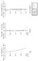
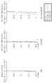
도 2 내지 도 4는 각각 본 발명의 제1실시예에 따른 줌 렌즈의 광각단, 중간단 및 망원단에서의 구면수차, 상면만곡, 왜곡수차를 나타낸 것이다. 상면만곡으로는 자오상면 만곡(T: tangential field curvature)과 구결상면 만곡(S: sagittal field curvature)을 보여준다.FIGS. 2 to 4 show spherical aberration, surface curvature, and distortion aberration at the wide angle end, the middle end, and the telephoto end, respectively, of the zoom lens according to the first embodiment of the present invention. Tangential field curvature (T) and sagittal field curvature (S) are shown for the curvature of field.
<제 2실시예>≪ Embodiment 2 >
도 5는 제2실시예에 따른 줌 렌즈를 도시한 것으로, 제1, 제2, 제3 및 제4 렌즈군(G1)(G2)(G3)(G4)을 포함한다.FIG. 5 shows a zoom lens according to the second embodiment, and includes first, second, third and fourth lens groups G1, G2, G3 and G4.
f ; 6.8mm ~ 11.58mm ~ 30.64mm 2ω ; 60.6˚ ~ 36.0˚ ~ 21.5˚ f; 6.8 mm to 11.58 mm to 30.64 mm 2 ?; 60.6˚ ~ 36.0˚ ~ 21.5˚
R Dn nd vd R Dn nd vd
OBJ: INFINITY INFINITY OBJ: INFINITY INFINITY
S1: 17.98000 0.600 1.92286 20.88 S1: 17.98000 0.600 1.92286 20.88
S2: 8.49100 2.179 S2: 8.49100 2.179
S3: INFINITY 7.600 1.83400 37.34 S3: INFINITY 7.600 1.83400 37.34
S4: INFINITY 0.300 S4: INFINITY 0.300
*S5: 17.93169 2.300 1.73968 49.00 * S5: 17.93169 2.300 1.73968 49.00
*S6: -19.28619 D1 * S6: -19.28619 D1
S7: -81.10900 0.600 1.76802 49.24 S7: -81.10900 0.600 1.76802 49.24
*S8: 9.39800 1.034 * S8: 9.39800 1.034
S9: -10.38200 0.500 1.62299 58.12 S9: -10.38200 0.500 1.62299 58.12
S10: 9.22400 1.500 1.84666 23.78 S10: 9.22400 1.500 1.84666 23.78
S11: 362.69100 D2 S11: 362.69100 D2
S12(ST) INFINITY 0.300 S12 (ST) INFINITY 0.300
*S13: 6.65307 1.500 1.80470 40.90 * S13: 6.65307 1.500 1.80470 40.90
S14: -32.68848 0.458 S14: -32.68848 0.458
S15: 8.49400 1.440 1.62299 58.12 S15: 8.49400 1.440 1.62299 58.12
S16: -8.49400 0.500 1.90366 31.32 S16: -8.49400 0.500 1.90366 31.32
S17: 5.10500 D3 S17: 5.10500 D3
S18: 6.80200 1.000 1.92286 20.88 S18: 6.80200 1.000 1.92286 20.88
S19: 5.04400 2.480 1.48749 70.44 S19: 5.04400 2.480 1.48749 70.44
S20: 289.72200 0.359 S20: 289.72200 0.359
*S21: 16.94758 1.650 1.51680 64.20 * S21: 16.94758 1.650 1.51680 64.20
S22: 26.78800 D4 S22: 26.78800 D4
S23: INFINITY 0.500 1.51680 64.20 S23: INFINITY 0.500 1.51680 64.20
S24: INFINITY 0.500 S24: INFINITY 0.500
S25: INFINITY 0.500 1.51680 64.20 S25: INFINITY 0.500 1.51680 64.20
S26: INFINITY S26: INFINITY
다음은 제2실시예에 따른 줌 렌즈에서의 가변 거리(D1)(D2)(D3)(D4)를 광각단, 중간단 및 망원단에 대해 나타낸 것이다.The following shows the variable distances D1, D2, D3 and D4 in the zoom lens according to the second embodiment with respect to the wide-angle end, the middle end and the telephoto end.
다음 표 4는 비구면 계수를 나타낸 것이다.Table 4 below shows the aspheric coefficients.
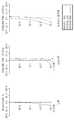
도 6 내지 도 8은 각각 본 발명의 제2실시예에 따른 줌 렌즈의 광각단, 중간단 및 망원단에서의 구면수차, 상면만곡, 왜곡수차를 나타낸 것이다.FIGS. 6 to 8 show spherical aberration, surface curvature, and distortion aberration at the wide angle end, the middle end, and the telephoto end, respectively, of the zoom lens according to the second embodiment of the present invention.
<제 3실시예>≪ Third Embodiment >
도 9는 제3실시예에 따른 줌 렌즈를 도시한 것이다.9 shows a zoom lens according to the third embodiment.
f ; 6.9mm ~ 10.35mm ~ 19.67mm 2ω ; 60.6˚ ~ 36.0˚ ~ 21.5˚ f; 6.9 mm to 10.35 mm to 19.67 mm 2 ?; 60.6˚ ~ 36.0˚ ~ 21.5˚
R Dn nd vd R Dn nd vd
OBJ: INFINITY INFINITY OBJ: INFINITY INFINITY
S1: 16.74487 0.620 1.92286 20.88 S1: 16.74487 0.620 1.92286 20.88
S2: 8.32722 2.220 S2: 8.32722 2.220
S3: INFINITY 7.500 1.83400 37.34 S3: INFINITY 7.500 1.83400 37.34
S4: INFINITY 0.300 S4: INFINITY 0.300
*S5: 18.69281 2.280 1.74330 49.33 * S5: 18.69281 2.280 1.74330 49.33
*S6: -19.16466 D1 * S6: -19.16466 D1
S7: -30.87977 0.600 1.76802 49.24 S7: -30.87977 0.600 1.76802 49.24
*S8: 10.00673 0.895 * S8: 10.00673 0.895
S9: -14.83817 0.500 1.62280 56.91 S9: -14.83817 0.500 1.62280 56.91
S10: 7.46253 1.500 1.84666 23.78 S10: 7.46253 1.500 1.84666 23.78
S11: 55.41687 D2 S11: 55.41687 D2
S12(ST): INFINITY 0.300 S12 (ST): INFINITY 0.300
*S13: 6.54046 1.500 1.80610 40.73 * S13: 6.54046 1.500 1.80610 40.73
S14: -35.60971 0.540 S14: -35.60971 0.540
S15: 8.17934 1.480 1.64000 60.20 S15: 8.17934 1.480 1.64000 60.20
S16: -6.62501 0.500 1.90366 31.32 S16: -6.62501 0.500 1.90366 31.32
S17: 5.07519 D3 S17: 5.07519 D3
S18: 7.19606 0.690 1.84666 23.78 S18: 7.19606 0.690 1.84666 23.78
S19: 5.29454 2.697 1.51680 64.20 S19: 5.29454 2.697 1.51680 64.20
S20: -54.50314 0.150 S20: -54.50314 0.150
*S21: 20.74980 2.034 1.53113 55.70 (Plastic ASP Lens) * S21: 20.74980 2.034 1.53113 55.70 (Plastic ASP Lens)
S22: 22.56161 D4 S22: 22.56161 D4
S23: INFINITY 0.500 1.51680 64.20 S23: INFINITY 0.500 1.51680 64.20
S24: INFINITY 0.500 S24: INFINITY 0.500
S25: INFINITY 0.500 1.51680 64.20 S25: INFINITY 0.500 1.51680 64.20
S26: INFINITY S26: INFINITY
다음은 제3실시예에 따른 줌 렌즈에서의 가변 거리(D1)(D2)(D3)(D4)를 광각단, 중간단 및 망원단에 대해 나타낸 것이다.The following describes the variable distances D1, D2, D3 and D4 in the zoom lens according to the third embodiment with respect to the wide-angle end, the middle end and the telephoto end.
다음 표 6은 비구면 계수를 나타낸 것이다.Table 6 below shows the aspheric coefficients.
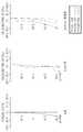
도 10 내지 도 12는 각각 본 발명의 제3실시예에 따른 줌 렌즈의 광각단, 중간단 및 망원단에서의 구면수차, 상면만곡, 왜곡수차를 나타낸 것이다.FIGS. 10 to 12 show spherical aberration, surface curvature, and distortion aberration at the wide angle end, the middle end, and the telephoto end, respectively, of the zoom lens according to the third embodiment of the present invention.
다음은, 상기 제1 내지 제3 실시예가 각각 상기 수학식 1과 2의 조건을 만족시킴을 보여준 것이다.The following shows that the first to third embodiments described above satisfy the above-mentioned conditions (1) and (2), respectively.
상기한 실시예들은 예시적인 것에 불과한 것으로, 당해 기술분야의 통상을 지식을 가진 자라면 이로부터 다양한 변형 및 균등한 타 실시예가 가능하다. 따라서, 본 발명의 진정한 기술적 보호범위는 하기의 특허청구범위에 기재된 발명의 기술적 사상에 의해 정해져야만 할 것이다.The above-described embodiments are merely illustrative, and various modifications and equivalent other embodiments are possible without departing from the scope of the present invention. Accordingly, the true scope of protection of the present invention should be determined by the technical idea of the invention described in the following claims.
도 1은 본 발명의 제1실시예에 따른 줌 렌즈를 광각단, 중간단, 망원단별로 나타낸 것이다.FIG. 1 is a view showing a zoom lens according to a first embodiment of the present invention in a wide-angle end, a middle end, and a telephoto end.
도 2 내지 도 4는 본 발명의 제1실시예에 따른 줌 렌즈의 광각단, 중간단 및 망원단에서의 수차도를 나타낸 것이다.FIGS. 2 to 4 show aberration diagrams at the wide angle end, the middle end, and the telephoto end of the zoom lens according to the first embodiment of the present invention.
도 5는 본 발명의 제2실시예에 따른 줌 렌즈를 광각단, 중간단, 망원단별로 나타낸 것이다.FIG. 5 is a view showing a zoom lens according to a second embodiment of the present invention in a wide-angle end, a middle end, and a telephoto end.
도 6 내지 8은 본 발명의 제2실시예에 따른 줌 렌즈의 광각단, 중간단 및 망원단에서의 수차도를 나타낸 것이다.6 to 8 show aberration diagrams at the wide angle end, the middle end, and the telephoto end of the zoom lens according to the second embodiment of the present invention.
도 9는 본 발명의 제3실시예에 따른 줌 렌즈를 광각단, 중간단, 망원단별로 나타낸 것이다.9 is a view showing a zoom lens according to a third embodiment of the present invention in a wide angle end, a middle end, and a telephoto end.
도 10 내지 12는 본 발명의 제3실시예에 따른 줌 렌즈의 광각단, 중간단 및 망원단에서의 수차도를 나타낸 것이다.FIGS. 10 to 12 show aberration diagrams at the wide-angle end, the middle end, and the telephoto end of the zoom lens according to the third embodiment of the present invention.
<도면 중 주요 부분에 대한 설명>DESCRIPTION OF THE PREFERRED EMBODIMENTS
G1...제1렌즈군, G2...제2렌즈군,G1 ... first lens group, G2 ... second lens group,
G3...제3렌즈군, G4...제4렌즈군G3 third lens group, G4 fourth lens group
D1,D2,D3,D4...가변 거리D1, D2, D3, D4 ... variable distance
Claims (9)
Translated fromKoreanPriority Applications (3)
| Application Number | Priority Date | Filing Date | Title |
|---|---|---|---|
| KR1020070136590AKR101431538B1 (en) | 2007-12-24 | 2007-12-24 | Zoom lens system |
| US12/316,642US7791818B2 (en) | 2007-12-24 | 2008-12-15 | Zoom lens system |
| CN2008101844435ACN101482646B (en) | 2007-12-24 | 2008-12-24 | Zoom lens system |
Applications Claiming Priority (1)
| Application Number | Priority Date | Filing Date | Title |
|---|---|---|---|
| KR1020070136590AKR101431538B1 (en) | 2007-12-24 | 2007-12-24 | Zoom lens system |
Publications (2)
| Publication Number | Publication Date |
|---|---|
| KR20090068820A KR20090068820A (en) | 2009-06-29 |
| KR101431538B1true KR101431538B1 (en) | 2014-09-19 |
Family
ID=40788295
Family Applications (1)
| Application Number | Title | Priority Date | Filing Date |
|---|---|---|---|
| KR1020070136590AExpired - Fee RelatedKR101431538B1 (en) | 2007-12-24 | 2007-12-24 | Zoom lens system |
Country Status (3)
| Country | Link |
|---|---|
| US (1) | US7791818B2 (en) |
| KR (1) | KR101431538B1 (en) |
| CN (1) | CN101482646B (en) |
Families Citing this family (24)
| Publication number | Priority date | Publication date | Assignee | Title |
|---|---|---|---|---|
| KR101706265B1 (en)* | 2009-12-04 | 2017-02-14 | 삼성전자주식회사 | Zoom lens and image pickup device having the same |
| KR101673594B1 (en)* | 2010-02-01 | 2016-11-07 | 엘지이노텍 주식회사 | Zoom optical system |
| KR101204095B1 (en) | 2011-01-06 | 2012-11-27 | 삼성테크윈 주식회사 | Zoom lens system and photographing apparatus |
| TWI456286B (en)* | 2011-04-19 | 2014-10-11 | Ability Entpr Co Ltd | Zoom lens |
| TWI443404B (en)* | 2011-05-27 | 2014-07-01 | Asia Optical Co Inc | Fixed focus projection lens |
| CN102879888B (en)* | 2011-07-15 | 2014-12-17 | 亚洲光学股份有限公司 | Fixed focus projection lens |
| JP6149359B2 (en)* | 2012-08-09 | 2017-06-21 | 株式会社ニコン | Variable magnification optical system, optical device |
| KR101994713B1 (en) | 2013-04-22 | 2019-07-01 | 삼성전기주식회사 | Multi-layered ceramic capacitor and board for mounting the same |
| US9857568B2 (en) | 2013-07-04 | 2018-01-02 | Corephotonics Ltd. | Miniature telephoto lens assembly |
| JP2016523389A (en) | 2013-07-04 | 2016-08-08 | コアフォトニクス リミテッド | Compact telephoto lens assembly |
| CN104142569B (en)* | 2014-08-19 | 2017-04-26 | 中山联合光电科技有限公司 | Small-size, high-resolution and large-image-surface zoom optical system |
| CN112433331B (en) | 2015-01-03 | 2022-07-08 | 核心光电有限公司 | Miniature telephoto lens module and camera using the same |
| JP6436184B2 (en)* | 2017-05-23 | 2018-12-12 | 株式会社ニコン | Variable magnification optical system, optical device |
| US11336830B2 (en) | 2019-01-03 | 2022-05-17 | Corephotonics Ltd. | Multi-aperture cameras with at least one two state zoom camera |
| US12072609B2 (en) | 2019-09-24 | 2024-08-27 | Corephotonics Ltd. | Slim pop-out cameras and lenses for such cameras |
| US11770609B2 (en) | 2020-05-30 | 2023-09-26 | Corephotonics Ltd. | Systems and methods for obtaining a super macro image |
| US12372737B2 (en)* | 2020-08-28 | 2025-07-29 | Zebra Technologies Corporation | Autofocus optical arrangements and assemblies including voice coil motors |
| KR20250008791A (en) | 2020-12-01 | 2025-01-15 | 코어포토닉스 리미티드 | Folded camera with continuously adaptive zoom factor |
| CN117425062A (en) | 2021-01-25 | 2024-01-19 | 核心光电有限公司 | Lens system for compact digital camera |
| WO2022200965A1 (en)* | 2021-03-22 | 2022-09-29 | Corephotonics Ltd. | Folded cameras with continuously adaptive zoom factor |
| KR20240012438A (en) | 2021-06-23 | 2024-01-29 | 코어포토닉스 리미티드 | Compact folded tele camera |
| US12235418B2 (en) | 2021-08-31 | 2025-02-25 | Zebra Technologies Corporation | Telephoto lens for compact long range barcode reader |
| CN120315167A (en) | 2021-12-14 | 2025-07-15 | 核心光电有限公司 | Large aperture compact scan telephoto camera |
| WO2025175518A1 (en)* | 2024-02-22 | 2025-08-28 | Huawei Technologies Co., Ltd. | Optical system and electronic device |
Citations (2)
| Publication number | Priority date | Publication date | Assignee | Title |
|---|---|---|---|---|
| JP2007148056A (en)* | 2005-11-29 | 2007-06-14 | Canon Inc | Zoom optical system |
| JP2007271692A (en)* | 2006-03-30 | 2007-10-18 | Matsushita Electric Ind Co Ltd | High magnification zoom lens |
Family Cites Families (12)
| Publication number | Priority date | Publication date | Assignee | Title |
|---|---|---|---|---|
| JP2000081572A (en)* | 1998-09-04 | 2000-03-21 | Fuji Photo Optical Co Ltd | Zoom lens |
| JP2006113363A (en) | 2004-10-15 | 2006-04-27 | Konica Minolta Opto Inc | Zoom lens and imaging apparatus |
| JP4650676B2 (en)* | 2005-03-03 | 2011-03-16 | ソニー株式会社 | Zoom lens and imaging device |
| JP4717480B2 (en) | 2005-03-25 | 2011-07-06 | 富士フイルム株式会社 | Zoom lens |
| JP2006317478A (en)* | 2005-05-10 | 2006-11-24 | Konica Minolta Photo Imaging Inc | Variable magnification optical system |
| JP4766929B2 (en) | 2005-06-10 | 2011-09-07 | オリンパスイメージング株式会社 | Image pickup apparatus having an optical path folding zoom lens |
| JP2007003776A (en)* | 2005-06-23 | 2007-01-11 | Sony Corp | Zoom lens and imaging apparatus |
| JP2007033879A (en)* | 2005-07-27 | 2007-02-08 | Sony Corp | Imaging lens device and imaging apparatus |
| JP4903418B2 (en) | 2005-11-18 | 2012-03-28 | イーストマン コダック カンパニー | Zoom lens |
| JP2007219316A (en) | 2006-02-17 | 2007-08-30 | Nikon Corp | Zoom lens and optical apparatus having the same |
| JP4631872B2 (en)* | 2006-05-01 | 2011-02-16 | 株式会社ニコン | Zoom lens and optical apparatus having the same |
| EP2015122A4 (en)* | 2006-05-01 | 2010-11-03 | Nikon Corp | Zoom lens and optical device with the same |
- 2007
- 2007-12-24KRKR1020070136590Apatent/KR101431538B1/ennot_activeExpired - Fee Related
- 2008
- 2008-12-15USUS12/316,642patent/US7791818B2/enactiveActive
- 2008-12-24CNCN2008101844435Apatent/CN101482646B/ennot_activeExpired - Fee Related
Patent Citations (2)
| Publication number | Priority date | Publication date | Assignee | Title |
|---|---|---|---|---|
| JP2007148056A (en)* | 2005-11-29 | 2007-06-14 | Canon Inc | Zoom optical system |
| JP2007271692A (en)* | 2006-03-30 | 2007-10-18 | Matsushita Electric Ind Co Ltd | High magnification zoom lens |
Also Published As
| Publication number | Publication date |
|---|---|
| US7791818B2 (en) | 2010-09-07 |
| KR20090068820A (en) | 2009-06-29 |
| CN101482646B (en) | 2012-05-30 |
| CN101482646A (en) | 2009-07-15 |
| US20090161228A1 (en) | 2009-06-25 |
Similar Documents
| Publication | Publication Date | Title |
|---|---|---|
| KR101431538B1 (en) | Zoom lens system | |
| CN108490592B (en) | Zoom optical system | |
| JP4378188B2 (en) | Zoom lens and imaging apparatus having the same | |
| KR101932722B1 (en) | Zoom lens and photographing apparatus having the same | |
| WO2012077338A1 (en) | Zoom lens and imaging device | |
| CN110832376A (en) | Variable magnification optical system, optical device, and method for manufacturing variable magnification optical system | |
| JP2005128186A (en) | Zoom lens, and video camera and digital still camera using the same | |
| KR101431539B1 (en) | Zoom lens system | |
| CN108369329B (en) | Zoom lens and optical apparatus | |
| JP7373331B2 (en) | Zoom lens and imaging device | |
| JP4817699B2 (en) | Zoom lens and imaging apparatus having the same | |
| US20210255423A1 (en) | Zoom lens, optical apparatus and method for manufacturing the zoom lens | |
| JP4593971B2 (en) | Zoom lens and imaging apparatus having the same | |
| CN105785559A (en) | Wide-angle zoom lens and image pickup apparatus | |
| JP5213727B2 (en) | Zoom lens and imaging apparatus having the same | |
| KR20220168423A (en) | Optical imaging system | |
| CN108604003B (en) | Zoom lens and optical apparatus | |
| KR101880633B1 (en) | Zoom lens and photographing device having the same | |
| KR101204095B1 (en) | Zoom lens system and photographing apparatus | |
| JP4972900B2 (en) | Zoom lens | |
| KR101271733B1 (en) | Zoom lens system | |
| KR101416237B1 (en) | Zoom lens | |
| JP2024120449A (en) | Zoom lens and imaging device | |
| JP4951915B2 (en) | Zoom lens | |
| JP4580510B2 (en) | Zoom lens |
Legal Events
| Date | Code | Title | Description |
|---|---|---|---|
| PA0109 | Patent application | St.27 status event code:A-0-1-A10-A12-nap-PA0109 | |
| N231 | Notification of change of applicant | ||
| PN2301 | Change of applicant | St.27 status event code:A-3-3-R10-R13-asn-PN2301 St.27 status event code:A-3-3-R10-R11-asn-PN2301 | |
| PG1501 | Laying open of application | St.27 status event code:A-1-1-Q10-Q12-nap-PG1501 | |
| N231 | Notification of change of applicant | ||
| PN2301 | Change of applicant | St.27 status event code:A-3-3-R10-R13-asn-PN2301 St.27 status event code:A-3-3-R10-R11-asn-PN2301 | |
| R18-X000 | Changes to party contact information recorded | St.27 status event code:A-3-3-R10-R18-oth-X000 | |
| A201 | Request for examination | ||
| PA0201 | Request for examination | St.27 status event code:A-1-2-D10-D11-exm-PA0201 | |
| D13-X000 | Search requested | St.27 status event code:A-1-2-D10-D13-srh-X000 | |
| D14-X000 | Search report completed | St.27 status event code:A-1-2-D10-D14-srh-X000 | |
| E902 | Notification of reason for refusal | ||
| PE0902 | Notice of grounds for rejection | St.27 status event code:A-1-2-D10-D21-exm-PE0902 | |
| E13-X000 | Pre-grant limitation requested | St.27 status event code:A-2-3-E10-E13-lim-X000 | |
| P11-X000 | Amendment of application requested | St.27 status event code:A-2-2-P10-P11-nap-X000 | |
| P13-X000 | Application amended | St.27 status event code:A-2-2-P10-P13-nap-X000 | |
| E701 | Decision to grant or registration of patent right | ||
| PE0701 | Decision of registration | St.27 status event code:A-1-2-D10-D22-exm-PE0701 | |
| GRNT | Written decision to grant | ||
| PR0701 | Registration of establishment | St.27 status event code:A-2-4-F10-F11-exm-PR0701 | |
| PR1002 | Payment of registration fee | St.27 status event code:A-2-2-U10-U11-oth-PR1002 Fee payment year number:1 | |
| PG1601 | Publication of registration | St.27 status event code:A-4-4-Q10-Q13-nap-PG1601 | |
| PR1001 | Payment of annual fee | St.27 status event code:A-4-4-U10-U11-oth-PR1001 Fee payment year number:4 | |
| FPAY | Annual fee payment | Payment date:20180727 Year of fee payment:5 | |
| PR1001 | Payment of annual fee | St.27 status event code:A-4-4-U10-U11-oth-PR1001 Fee payment year number:5 | |
| FPAY | Annual fee payment | Payment date:20190730 Year of fee payment:6 | |
| PR1001 | Payment of annual fee | St.27 status event code:A-4-4-U10-U11-oth-PR1001 Fee payment year number:6 | |
| PR1001 | Payment of annual fee | St.27 status event code:A-4-4-U10-U11-oth-PR1001 Fee payment year number:7 | |
| PR1001 | Payment of annual fee | St.27 status event code:A-4-4-U10-U11-oth-PR1001 Fee payment year number:8 | |
| P22-X000 | Classification modified | St.27 status event code:A-4-4-P10-P22-nap-X000 | |
| PR1001 | Payment of annual fee | St.27 status event code:A-4-4-U10-U11-oth-PR1001 Fee payment year number:9 | |
| PC1903 | Unpaid annual fee | St.27 status event code:A-4-4-U10-U13-oth-PC1903 Not in force date:20230813 Payment event data comment text:Termination Category : DEFAULT_OF_REGISTRATION_FEE | |
| PC1903 | Unpaid annual fee | St.27 status event code:N-4-6-H10-H13-oth-PC1903 Ip right cessation event data comment text:Termination Category : DEFAULT_OF_REGISTRATION_FEE Not in force date:20230813 |