KR101427946B1 - Method for controlling air blower of fuel cell vehicle - Google Patents
Method for controlling air blower of fuel cell vehicleDownload PDFInfo
- Publication number
- KR101427946B1 KR101427946B1KR1020120145738AKR20120145738AKR101427946B1KR 101427946 B1KR101427946 B1KR 101427946B1KR 1020120145738 AKR1020120145738 AKR 1020120145738AKR 20120145738 AKR20120145738 AKR 20120145738AKR 101427946 B1KR101427946 B1KR 101427946B1
- Authority
- KR
- South Korea
- Prior art keywords
- high voltage
- air blower
- power converter
- fuel cell
- voltage battery
- Prior art date
- Legal status (The legal status is an assumption and is not a legal conclusion. Google has not performed a legal analysis and makes no representation as to the accuracy of the status listed.)
- Active
Links
- 239000000446fuelSubstances0.000titleclaimsabstractdescription42
- 238000000034methodMethods0.000titleclaimsabstractdescription15
- 230000001172regenerating effectEffects0.000claimsabstractdescription39
- 238000001514detection methodMethods0.000claimsdescription3
- 230000008929regenerationEffects0.000claims1
- 238000011069regeneration methodMethods0.000claims1
- 239000012528membraneSubstances0.000description9
- 239000001257hydrogenSubstances0.000description7
- 229910052739hydrogenInorganic materials0.000description7
- 239000007789gasSubstances0.000description5
- -1hydrogen ionsChemical class0.000description5
- 239000003792electrolyteSubstances0.000description4
- QVGXLLKOCUKJST-UHFFFAOYSA-Natomic oxygenChemical compound[O]QVGXLLKOCUKJST-UHFFFAOYSA-N0.000description3
- 239000001301oxygenSubstances0.000description3
- 229910052760oxygenInorganic materials0.000description3
- UFHFLCQGNIYNRP-UHFFFAOYSA-NHydrogenChemical compound[H][H]UFHFLCQGNIYNRP-UHFFFAOYSA-N0.000description2
- 239000003054catalystSubstances0.000description2
- 238000006243chemical reactionMethods0.000description2
- 239000000498cooling waterSubstances0.000description2
- 238000010586diagramMethods0.000description2
- 238000009792diffusion processMethods0.000description2
- 238000001035dryingMethods0.000description2
- 239000005518polymer electrolyteSubstances0.000description2
- 239000000126substanceSubstances0.000description2
- HEZMWWAKWCSUCB-PHDIDXHHSA-N(3R,4R)-3,4-dihydroxycyclohexa-1,5-diene-1-carboxylic acidChemical compoundO[C@@H]1C=CC(C(O)=O)=C[C@H]1OHEZMWWAKWCSUCB-PHDIDXHHSA-N0.000description1
- 238000005341cation exchangeMethods0.000description1
- 238000002485combustion reactionMethods0.000description1
- 239000004020conductorSubstances0.000description1
- 238000003487electrochemical reactionMethods0.000description1
- 238000001914filtrationMethods0.000description1
- 230000006698inductionEffects0.000description1
- 239000007800oxidant agentSubstances0.000description1
- 238000010248power generationMethods0.000description1
- 238000005086pumpingMethods0.000description1
- XLYOFNOQVPJJNP-UHFFFAOYSA-NwaterSubstancesOXLYOFNOQVPJJNP-UHFFFAOYSA-N0.000description1
Images

Classifications
- B—PERFORMING OPERATIONS; TRANSPORTING
- B60—VEHICLES IN GENERAL
- B60L—PROPULSION OF ELECTRICALLY-PROPELLED VEHICLES; SUPPLYING ELECTRIC POWER FOR AUXILIARY EQUIPMENT OF ELECTRICALLY-PROPELLED VEHICLES; ELECTRODYNAMIC BRAKE SYSTEMS FOR VEHICLES IN GENERAL; MAGNETIC SUSPENSION OR LEVITATION FOR VEHICLES; MONITORING OPERATING VARIABLES OF ELECTRICALLY-PROPELLED VEHICLES; ELECTRIC SAFETY DEVICES FOR ELECTRICALLY-PROPELLED VEHICLES
- B60L50/00—Electric propulsion with power supplied within the vehicle
- B60L50/50—Electric propulsion with power supplied within the vehicle using propulsion power supplied by batteries or fuel cells
- H—ELECTRICITY
- H02—GENERATION; CONVERSION OR DISTRIBUTION OF ELECTRIC POWER
- H02P—CONTROL OR REGULATION OF ELECTRIC MOTORS, ELECTRIC GENERATORS OR DYNAMO-ELECTRIC CONVERTERS; CONTROLLING TRANSFORMERS, REACTORS OR CHOKE COILS
- H02P3/00—Arrangements for stopping or slowing electric motors, generators, or dynamo-electric converters
- H02P3/06—Arrangements for stopping or slowing electric motors, generators, or dynamo-electric converters for stopping or slowing an individual dynamo-electric motor or dynamo-electric converter
- H02P3/08—Arrangements for stopping or slowing electric motors, generators, or dynamo-electric converters for stopping or slowing an individual dynamo-electric motor or dynamo-electric converter for stopping or slowing a DC motor
- H02P3/14—Arrangements for stopping or slowing electric motors, generators, or dynamo-electric converters for stopping or slowing an individual dynamo-electric motor or dynamo-electric converter for stopping or slowing a DC motor by regenerative braking
- H—ELECTRICITY
- H01—ELECTRIC ELEMENTS
- H01M—PROCESSES OR MEANS, e.g. BATTERIES, FOR THE DIRECT CONVERSION OF CHEMICAL ENERGY INTO ELECTRICAL ENERGY
- H01M10/00—Secondary cells; Manufacture thereof
- H01M10/42—Methods or arrangements for servicing or maintenance of secondary cells or secondary half-cells
- H01M10/44—Methods for charging or discharging
- H—ELECTRICITY
- H01—ELECTRIC ELEMENTS
- H01M—PROCESSES OR MEANS, e.g. BATTERIES, FOR THE DIRECT CONVERSION OF CHEMICAL ENERGY INTO ELECTRICAL ENERGY
- H01M16/00—Structural combinations of different types of electrochemical generators
- H01M16/003—Structural combinations of different types of electrochemical generators of fuel cells with other electrochemical devices, e.g. capacitors, electrolysers
- H01M16/006—Structural combinations of different types of electrochemical generators of fuel cells with other electrochemical devices, e.g. capacitors, electrolysers of fuel cells with rechargeable batteries
- H—ELECTRICITY
- H01—ELECTRIC ELEMENTS
- H01M—PROCESSES OR MEANS, e.g. BATTERIES, FOR THE DIRECT CONVERSION OF CHEMICAL ENERGY INTO ELECTRICAL ENERGY
- H01M8/00—Fuel cells; Manufacture thereof
- H01M8/04—Auxiliary arrangements, e.g. for control of pressure or for circulation of fluids
- H01M8/04298—Processes for controlling fuel cells or fuel cell systems
- H01M8/043—Processes for controlling fuel cells or fuel cell systems applied during specific periods
- H01M8/04303—Processes for controlling fuel cells or fuel cell systems applied during specific periods applied during shut-down
- H—ELECTRICITY
- H01—ELECTRIC ELEMENTS
- H01M—PROCESSES OR MEANS, e.g. BATTERIES, FOR THE DIRECT CONVERSION OF CHEMICAL ENERGY INTO ELECTRICAL ENERGY
- H01M8/00—Fuel cells; Manufacture thereof
- H01M8/04—Auxiliary arrangements, e.g. for control of pressure or for circulation of fluids
- H01M8/04298—Processes for controlling fuel cells or fuel cell systems
- H01M8/04694—Processes for controlling fuel cells or fuel cell systems characterised by variables to be controlled
- H01M8/04746—Pressure; Flow
- H01M8/04753—Pressure; Flow of fuel cell reactants
- Y—GENERAL TAGGING OF NEW TECHNOLOGICAL DEVELOPMENTS; GENERAL TAGGING OF CROSS-SECTIONAL TECHNOLOGIES SPANNING OVER SEVERAL SECTIONS OF THE IPC; TECHNICAL SUBJECTS COVERED BY FORMER USPC CROSS-REFERENCE ART COLLECTIONS [XRACs] AND DIGESTS
- Y02—TECHNOLOGIES OR APPLICATIONS FOR MITIGATION OR ADAPTATION AGAINST CLIMATE CHANGE
- Y02E—REDUCTION OF GREENHOUSE GAS [GHG] EMISSIONS, RELATED TO ENERGY GENERATION, TRANSMISSION OR DISTRIBUTION
- Y02E60/00—Enabling technologies; Technologies with a potential or indirect contribution to GHG emissions mitigation
- Y02E60/10—Energy storage using batteries
- Y—GENERAL TAGGING OF NEW TECHNOLOGICAL DEVELOPMENTS; GENERAL TAGGING OF CROSS-SECTIONAL TECHNOLOGIES SPANNING OVER SEVERAL SECTIONS OF THE IPC; TECHNICAL SUBJECTS COVERED BY FORMER USPC CROSS-REFERENCE ART COLLECTIONS [XRACs] AND DIGESTS
- Y02—TECHNOLOGIES OR APPLICATIONS FOR MITIGATION OR ADAPTATION AGAINST CLIMATE CHANGE
- Y02E—REDUCTION OF GREENHOUSE GAS [GHG] EMISSIONS, RELATED TO ENERGY GENERATION, TRANSMISSION OR DISTRIBUTION
- Y02E60/00—Enabling technologies; Technologies with a potential or indirect contribution to GHG emissions mitigation
- Y02E60/30—Hydrogen technology
- Y02E60/50—Fuel cells
Landscapes
- Engineering & Computer Science (AREA)
- Life Sciences & Earth Sciences (AREA)
- Sustainable Energy (AREA)
- Sustainable Development (AREA)
- Chemical & Material Sciences (AREA)
- Electrochemistry (AREA)
- General Chemical & Material Sciences (AREA)
- Chemical Kinetics & Catalysis (AREA)
- Manufacturing & Machinery (AREA)
- Power Engineering (AREA)
- Transportation (AREA)
- Mechanical Engineering (AREA)
- Fuel Cell (AREA)
- Electric Propulsion And Braking For Vehicles (AREA)
Abstract
Translated fromKoreanDescription
Translated fromKorean본 발명은 연료전지 차량의 공기 블로워 제어방법에 관한 것으로, 보다 상세하게는 연료전지 차량의 키이 오프시에 공기 블로워의 작동 정지 시간을 단축시킬 수 있는 연료전지 차량의 공기 블로워 제어방법에 관한 것이다.BACKGROUND OF THE INVENTION 1. Field of the Invention [0001] The present invention relates to a method of controlling an air blower of a fuel cell vehicle, and more particularly, to a method of controlling an air blower of a fuel cell vehicle that can shorten an operation stoppage time of an air blower when a fuel cell vehicle is turned off.
일반적으로 연료전지는 연료가 가지고 있는 화학 에너지를 연소에 의해 열로 바꾸지 않고 연료전지 스택 내에서 전기 화학적으로 반응시켜 전기에너지로 변환시키는 일종의 발전장치로서, 산업용, 가정용 및 차량 구동용 전력을 공급할 뿐만 아니라 전기전자 제품 등에도 널리 사용되고 있다.Generally, a fuel cell is a kind of power generation device that converts chemical energy of a fuel into electric energy by reacting electrochemically in a fuel cell stack without converting it into heat by combustion, and supplies power for industrial, household and vehicle driving It is widely used in electric and electronic products.
상기와 같은 연료전지 중에 차량 구동용 에너지원으로 사용되는 고분자 전해질막 연료전지는, 수소 이온이 이동하는 전해질막을 중심으로 막의 양쪽에 전기화학 반응이 일어나는 촉매 전극층이 부착된 막전극접합체(MEA; Membrane Electrolyte Assembly), 반응 기체들을 고르게 분포시키고 발생된 전기에너지를 전달하는 역할을 하는 기체 확산층, 반응 기체들 및 냉각수의 기밀성과 적정 체결압을 유지하기 위한 개스킷과 체결기구, 및 상기 반응 기체들 및 냉각수를 이동시키는 분리판 등을 포함하여 구성된다.The polymer electrolyte membrane fuel cell used as an energy source for driving a vehicle includes a membrane electrode assembly (MEA) having a catalyst electrode layer on both sides of an electrolyte membrane on which hydrogen ions migrate, A gas diffusion layer serving to distribute the reacted gases evenly and to distribute the generated electric energy, a gasket and a fastening mechanism for maintaining the airtightness of the reaction gases and the cooling water, the proper tightening pressure, and the reaction gases and cooling water And a separating plate for moving the separating plate.
상기 고분자 전해질막 연료전지에서 연료인 수소와 산화제인 산소(공기)가 상기 분리판의 유로를 통해 상기 막전극접합체의 애노드(anode)와 캐소드(cathode)로 각각 공급되는 데, 수소는 애노드로 공급되는 반면에 산소(공기)는 캐소드로 공급된다.In the polymer electrolyte membrane fuel cell, hydrogen as fuel and oxygen (air) as an oxidizer are supplied to the anode and the cathode of the membrane electrode assembly via the flow path of the separator plate, respectively. While oxygen (air) is supplied to the cathode.
상기 애노드로 공급된 수소는 전해질막의 양쪽에 구성된 전극층의 촉매에 의해 수소이온과 전자로 분해되고, 이 중 수소 이온만이 선택적으로 양이온 교환막인 전해질막을 통과하여 캐소드로 전달되며, 이와 동시에 전자는 도체인 기체 확산층과 분리판을 통해 캐소드로 전달된다.The hydrogen supplied to the anode is decomposed into hydrogen ions and electrons by the catalyst of the electrode layer formed on both sides of the electrolyte membrane. Only the hydrogen ions are selectively transmitted to the cathode through the electrolyte membrane, which is a cation exchange membrane. At the same time, And is transferred to the cathode through the gas diffusion layer and the separator.
상기 캐소드에서는 전해질막을 통해 공급된 수소 이온과 분리판을 통해 전달된 전자가 공기공급장치에 의해 캐소드로 공급된 공기 중의 산소와 만나서 물을 생성하는 반응을 일으킨다. 이때에 일어나는 수소 이온의 이동에 기인하여 외부 도선을 통한 전자의 흐름이 발생해서 전류가 생성된다.In the cathode, the hydrogen ions supplied through the electrolyte membrane and the electrons transferred through the separator meet with oxygen in the air supplied to the cathode by the air supply device to produce water. At this time, due to the movement of the hydrogen ions, a flow of electrons through the external conductor occurs and a current is generated.
상기 공기공급장치로서는 공기 중에 포함된 이물질을 여과하는 에어 클리너와, 상기 에어 클리너에서 여과된 공기를 압축하여 공급하는 공기 블로워 및 상기 공기 블로워를 제어하는 컨트롤러(Blower Pump control unit: BPCU)를 포함한다.The air supply device includes an air cleaner for filtering foreign substances contained in the air, an air blower for compressing and supplying the air filtered by the air cleaner, and a controller (Blower Pump control unit: BPCU) for controlling the air blower .
상기와 같은 공기공급장치를 구비한 연료전지 차량에서 키이 오프시에 고속으로 운전되는 공기 블로워의 회전수를 회생 제동을 통해 빨리 낮추어서 연료전지 스택내로의 공기 공급을 차단하여 막전극접합체(MEA)의 건조를 방지해야 한다.In the fuel cell vehicle having the above-described air supply device, the number of revolutions of the air blower operating at high speed at the time of key off is quickly lowered through regenerative braking to cut off air supply into the fuel cell stack, Drying should be prevented.
그런데 연료전지 차량의 모든 고전압 부품들이 정상인 경우에 공기 블로워의 회생 제동을 통해 발생한 회생 에너지를 고전압 배터리로 충전이 가능하지만, 고전압 배터리나 혹은 고전압 전력변환기(High Voltage DCDC Converter; HDC)가 페일되면 상기 공기 블로워를 회생 제동을 통해 단시간에 정지시키기가 불가능하게 되고 문제점이 있었다.However, when all the high voltage components of the fuel cell vehicle are normal, the regenerative energy generated through the regenerative braking of the air blower can be charged with the high voltage battery. However, when the high voltage battery or the high voltage DCDC converter It is impossible to stop the air blower through a regenerative braking in a short time.
본 발명의 실시 예는 연료전지 차량의 키이 오프시에 공기 블로워의 회생 제동을 통해 발생된 전압을 모터의 고정자 저항을 이용하여 소거해서 공기 블로워를 단시간에 정지시킬 수 있는 연료전지 차량의 공기 블로워 제어방법을 제공하는 것이다.An embodiment of the present invention provides an air blower control of a fuel cell vehicle that can stop the air blower in a short time by erasing the voltage generated through regenerative braking of the air blower at the time of key off of the fuel cell vehicle using the stator resistance of the motor Method.
본 발명의 실시 예에 따른 연료전지 차량의 공기 블로워 제어방법은, 연료전지 차량의 키이 오프를 감지하는 키이 오프 감지단계, 상기 키이 오프 감지단계에서 키이 오프가 감지되면, 고전압 전력변환기와 고전압 배터리의 정상 작동 여부를 감지하는 정상 작동 여부 감지단계 및, 상기 정상 작동 여부 감지단계에서 상기 고전압 전력변환기와 고전압 배터리의 정상 작동 여부에 따라 공기 블로워의 회생제동으로 발생된 회생 에너지를 2가지 다른 경로를 통해 소진하는 공기블로워 회생 에너지 소진단계를 포함할 수 있다.A method of controlling an air blower of a fuel cell vehicle according to an embodiment of the present invention includes: detecting a key-off of a fuel cell vehicle; detecting a key-off of the fuel cell vehicle; The method of claim 1, wherein the regenerative energy generated by regenerative braking of the air blower according to whether the high-voltage power converter and the high-voltage battery are normally operated in the normal operation detection step is detected through two different paths And exhausting air blower regenerative energy exhaustion steps.
상기 공기 블로워 회생 에너지 소진단계는 상기 고전압 전력변환기와 고전압 배터리가 정상 작동 중일 때에 고전압 전력변환기의 전압 제어를 통해 고전압 배터리로 보내어 충전하는 단계를 포함할 수 있다.The air blower regenerative energy exhausting step may include charging the high voltage power converter and the high voltage battery to the high voltage battery through voltage control of the high voltage power converter when the high voltage battery is in normal operation.
상기 공기 블로워 회생 에너지 소진단계는 상기 고전압 전력변환기와 고전압 배터리가 정상 작동이지 않을 경우에는 모터 및 인버터의 고정자 저항을 이용하여 상기 회생 에너지를 소진시키는 단계를 포함할 수 있다.The step of exhausting the air blower regenerative energy may include exhausting the regenerative energy using the stator resistance of the motor and the inverter when the high voltage power converter and the high voltage battery are not in normal operation.
본 발명의 실시 예에 따른 연료전지 차량의 공기 블로워 제어방법에 의하면, 연료전지 차량이 키이 오프될 때에 연료전지 스택에 공기를 공급하는 공기 블로워를 회생 제동을 통해 단시간에 정지시켜 연료전지 스택의 건조를 효과적으로 방지할 수 있다.According to the air blower control method of the fuel cell vehicle according to the embodiment of the present invention, the air blower that supplies air to the fuel cell stack when the fuel cell vehicle is turned off is stopped in a short period of time through regenerative braking, Can be effectively prevented.
만일 고전압 전력변환기(HDC)나 혹은 고전압 배터리가 페일되어 공기 블로워의 회생 제동을 통해 발생된 회생 에너지를 충전할 수 없는 경우에는 모터 컨트롤러(MCU)를 통해 모터 쪽으로 회생 에너지를 보내어 모터의 고정자 저항을 이용해서 회생 에너지를 소거함으로써, 고전압 전력변환기나 혹은 고전압 배터리가 페일된 경우에도 공기 블로워를 단시간에 작동 정지시킬 수 있다.If the high voltage power converter (HDC) or the high voltage battery fails and the regenerative energy generated by regenerative braking of the air blower can not be charged, regenerative energy is sent to the motor through the motor controller (MCU) And the regenerative energy is erased by using the air blower, the air blower can be stopped in a short time even when the high voltage power converter or the high voltage battery is failed.
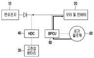
도 1은 본 발명의 실시 예에 따라 연료전지 차량이 키이 오프될 때에 고전압 전력변환기(HDC)와 고전압 배터리가 정상인 경우에 공기 블로워를 회생 제동시키는 연료전지 차량의 파워 시스템의 개념도이다.
도 2는 본 발명의 실시 예에 따라 연료전지 차량이 키이 오프될 때에 고전압 전력변환기(HDC)와 고전압 배터리가 페일된 경우에 공기 블로워의 회생 제동을 통해 발생된 회생 에너지를 모터로 보내어 소거하는 연료전지 차량의 파워 시스템의 개념도이다.
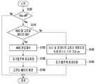
도 3은 본 발명의 실시 예에 따른 연료전지 차량의 공기 블로워 제어방법의 제어 흐름도이다.1 is a conceptual diagram of a power system of a fuel cell vehicle that regenerates an air blower when a fuel cell vehicle is keyed off and a high-voltage power converter (HDC) and a high-voltage battery are normal according to an embodiment of the present invention.
FIG. 2 is a graph showing the relationship between the output voltage of the high-voltage power converter HDC and the output voltage of the fuel cell vehicle when the high-voltage power converter HDC and the high-voltage battery fail when the fuel cell vehicle is turned off according to the embodiment of the present invention. Fig. 3 is a conceptual diagram of a power system of a battery vehicle.
3 is a control flowchart of the air blower control method of the fuel cell vehicle according to the embodiment of the present invention.
이하, 본 발명의 바람직한 실시 예를 첨부한 도면을 참조로 상세하게 설명하면 다음과 같다.Hereinafter, preferred embodiments of the present invention will be described in detail with reference to the accompanying drawings.
도 1을 참조하면, 본 발명의 실시 예에 따른 공기 블로워 제어방법을 수행하는 연료전지 차량의 파워 시스템의 구성이 개념적으로 도시되어 있는 바, 연료의 전기화학적인 반응을 통해 전기 에너지를 생산하는 연료전지(10)에 전기 에너지를 공급받아 구동되는 모터 및 이를 제어하는 인버터로서 모터 및 인버터(20)가 접속된다.Referring to FIG. 1, there is conceptually shown a configuration of a power system of a fuel cell vehicle that performs an air blower control method according to an embodiment of the present invention. The fuel system includes a fuel generating electrical energy through an electrochemical reaction of fuel A motor and an
또한 상기 연료전지(10)에는 전기에너지를 충전할 수 있는 고전압 배터리(30)가 고전압 전력변환기(HDC; 40)를 통해 접속된다.A
상기 고전압 전력변환기(HDC; 40)는 상기 연료전지(10)와 상기 모터 및 인버터(20) 사이에 병렬로 접속되어 상기 모터 및 인버터(20)의 모터에 공급되는 전압이 안전하게 유지되도록 하고, 상기 연료전지(10)와 고전압 배터리(30)의 서로 다른 출력 전압의 균형을 매칭시켜 주며, 상기 연료전지(10)의 잉여 전압 및 회생제동 에너지를 고전압 배터리(30) 측에서 충전 전압으로 제공되도록 한다.The high voltage power converter (HDC) 40 is connected in parallel between the
상기 모터 및 인버터(20)는 상기 모터의 구동을 제어하기 위한 모터제어기(Motor Control Unit; MCU)를 더 포함할 수 있다.The motor and the
또한 상기 연료전지(10) 혹은 고전압 배터리(30)로부터 전기 에너지를 공급받아 작동되면서 상기 연료전지(10)에 공기를 압축하여 공급하는 공기 블로워(50)가 그 제어기(60)를 통해 상기 고전압 배터리(30)에 연결된다.An
상기 제어기(60)는 상기 공기 블로워에서 공기를 압축하여 펌핑하는 펌프를 제어하는 제어기(Blower Pump Control Unit; BPCU)를 포함할 수 있다.The
이에 따라 연료전지 차량이 운행을 마치고 키이 오프될 때에 상기 공기 블로워(50)도 단시간에 작동 정지시켜 연료전지 스택의 불필요한 건조를 방지해야 하는 바, 상기 공기 블로워(50)를 단시간에 정시시키는 방법으로서 공기 블로워(50)를 회생 제동시킨다.Accordingly, when the fuel cell vehicle is operated and the key is turned off, the
상기 공기 블로워(50)를 회생 제동시킬 때에 상기 고전압 전력변환기(40)와 고전압 배터리(30)가 페일되지 않고 정상적으로 작동되면, 상기 공기 블로워(50)를 회생 제동시키고, 이때에 발생된 회생 에너지를 도 1에서 화살표로 도시된 바와 같이 상기 고전압 전력변환기(40)를 거쳐서 상기 고전압 배터리(30) 쪽으로 보내어 충전되게 한다.When the high-
그런데 상기 공기 블로워(50)를 회생 제동시킬 때에 상기 고전압 전력변환기(40)나 혹은 고전압 배터리(30)가 페일되면, 상기 공기 블로워(50)를 회생 제동시키는 과정에 발생한 회생 에너지를 상기 고전압 배터리(30)를 통해 충전할 수 없게 된다.When the high
상기와 같이 고전압 전력변환기(40)나 혹은 고전압 배터리(30)가 페일된 상태에서는 도 2에 화살표로 도시된 바와 같이 상기 블로워 펌프 제어기(60)를 통해 상기 모터 및 인버터(20)로 보내지고, 상기 모터 및 인버터(20)는, 모터에 토크를 발생시키지 않고 모터의 고정자 저항에 발열만 발생되도록 인버터를 제어하여 상기 회생 에너지를 소모시켜 제거함으로써, 공기 블로워(50)를 회생제동을 통해 빠르게 작동 정지시킬 수 있다.When the high
상기 모터 및 인버터(20)의 모터는 유동 전동기를 사용하고, 유도 전동기의 경우 회전자의 회전 주파수에 슬립 주파수를 더해야 만이 토크가 발생되는 바, 만약 슬립 주파수가 제로이면 토크가 발생되지 않으므로, 상기 공기 블로워(50)의 회생제동에 의해 발생된 회생 전기 에너지를 인가하여 소모시킬 수 있다.In the case of the induction motor, torque is generated only by adding the slip frequency to the rotational frequency of the rotor. If the slip frequency is zero, no torque is generated. Therefore, The regenerative electric energy generated by the regenerative braking of the
도 3을 참조하면, 본 발명의 실시 예에 따른 공기 블로워 제어방법의 흐름도가 도시되어 있는 바, 시작단계에서는 연료전지 차량의 키이 오프를 감지한다.(S100)Referring to FIG. 3, a flowchart of an air blower control method according to an embodiment of the present invention is shown. In a start step, a key off of a fuel cell vehicle is detected (S100)
상기 S100 단계에서 키이 오프가 감지되면, 고전압 전력변환기(HDC)와 고전압 배터리(30)의 정상작동 여부를 감지한다.(S110)If the key off is detected in step S100, it is detected whether the high voltage power converter (HDC) and the
상기 고전압 전력변환기(HDC)와 고전압 배터리(30)의 정상작동 여부에 따라 2가지 다른 경로를 통해 공기 블로워의 회생제동으로 발생된 회생 에너지를 소진하게 된다.Depending on the normal operation of the high voltage power converter (HDC) and the
즉 상기 고전압 전력변환기(HDC)와 고전압 배터리(30)가 정상 작동 중이면, 고전압 전력변환기(HDC)의 전압 제어(S120)를 통해 공기 블로워(50)의 회생제동(S130)으로 발생된 전기 에너지를 고전압 배터리(30)로 보내어 충전한다.(S140)When the high voltage power converter HDC and the
상기 고전압 전력변환기(HDC)와 고전압 배터리(30)가 정상 작동 중이 아니면, 모터 및 인버터(20)의 고정자 저항을 이용하여 회생 에너지를 소모할 기능을 준비하고(S150), 공기 블로워(50)를 회생 제동시켜(S160) 그 때에 발생하는 회생 전기 에너지를 고정자 저항을 통해 소거한다.If the high voltage power converter (HDC) and the
이상으로 본 발명에 관한 바람직한 실시 예를 설명하였으나, 본 발명은 상기 실시 예에 한정되지 아니하며, 본 발명의 실시예로부터 당해 발명이 속하는 기술분야에서 통상의 지식을 가진 자에 의한 용이하게 변경되어 균등하다고 인정되는 범위의 모든 변경을 포함한다.While the present invention has been described in connection with what is presently considered to be practical exemplary embodiments, it is to be understood that the invention is not limited to the disclosed embodiments, but, on the contrary, And all changes to the scope that are deemed to be valid.
10: 연료전지20: 모터 및 인버터
30: 고전압 배터리40: 고전압 전력변환기
50: 공기 블로워60: 블로워 펌프 제어기10: Fuel cell 20: Motor and inverter
30: High voltage battery 40: High voltage power converter
50: air blower 60: blower pump controller
Claims (3)
Translated fromKorean상기 키이 오프 감지단계에서 키이 오프가 감지되면, 고전압 전력변환기와 고전압 배터리의 정상 작동 여부를 감지하는 정상 작동 여부 감지단계;
상기 정상 작동 여부 감지단계에서 상기 고전압 전력변환기와 고전압 배터리의 정상 작동 여부에 따라 공기 블로워의 회생제동으로 발생된 회생 에너지를 2가지 다른 경로를 통해 소진하는 공기 블로워 회생 에너지 소진단계;
를 포함하는 연료전지 차량의 공기 블로워 제어방법.A key off detection step of detecting a key off of the fuel cell vehicle;
Detecting a normal operation state of the high voltage power converter and the high voltage battery when the key off is detected in the key off sensing step;
An air blower regeneration energy exhausting step of exhausting regenerative energy generated by regenerative braking of the air blower through two different paths depending on whether the high voltage power converter and the high voltage battery are normally operated in the normal operation detection step;
Wherein the air blower control method comprises the steps of:
상기 공기 블로워 회생 에너지 소진단계는 상기 고전압 전력변환기와 고전압 배터리가 정상 작동 중일 때에 고전압 전력변환기의 전압 제어를 통해 고전압 배터리로 보내어 충전하는 단계를 포함하는 것을 특징으로 하는 연료전지 차량의 공기 블로워 제어방법.The method of claim 1,
Wherein the air blower regenerative energy exhausting step includes charging the high voltage battery to the high voltage battery through voltage control of the high voltage power converter when the high voltage power converter and the high voltage battery are in normal operation, .
상기 공기 블로워 회생 에너지 소진단계는 상기 고전압 전력변환기와 고전압 배터리가 정상 작동이지 않을 경우에는, 토크를 발생시키지 않고 모터의 고정자 저항에 발열만 발생하도록 인버터를 제어하여 상기 회생 에너지를 소진시키는 단계를 포함하는 것을 특징으로 하는 연료전지 차량의 공기 블로워 제어방법.The method of claim 1,
The step of exhausting the air blower regenerative energy includes the step of exhausting the regenerative energy by controlling the inverter so that only the heat is generated in the stator resistance of the motor without generating torque when the high voltage power converter and the high voltage battery are not in normal operation Wherein said air blower control means comprises:
Priority Applications (4)
| Application Number | Priority Date | Filing Date | Title |
|---|---|---|---|
| KR1020120145738AKR101427946B1 (en) | 2012-12-13 | 2012-12-13 | Method for controlling air blower of fuel cell vehicle |
| US14/096,539US9130491B2 (en) | 2012-12-13 | 2013-12-04 | Method of controlling air blower of fuel cell vehicle |
| DE102013225366.4ADE102013225366B4 (en) | 2012-12-13 | 2013-12-10 | SYSTEM AND METHOD FOR CONTROLLING A FAN OF A FUEL CELL VEHICLE |
| CN201310757045.9ACN103869730B (en) | 2012-12-13 | 2013-12-12 | The system and method for controlling the air blower of fuel-cell vehicle |
Applications Claiming Priority (1)
| Application Number | Priority Date | Filing Date | Title |
|---|---|---|---|
| KR1020120145738AKR101427946B1 (en) | 2012-12-13 | 2012-12-13 | Method for controlling air blower of fuel cell vehicle |
Publications (2)
| Publication Number | Publication Date |
|---|---|
| KR20140080691A KR20140080691A (en) | 2014-07-01 |
| KR101427946B1true KR101427946B1 (en) | 2014-08-11 |
Family
ID=50878993
Family Applications (1)
| Application Number | Title | Priority Date | Filing Date |
|---|---|---|---|
| KR1020120145738AActiveKR101427946B1 (en) | 2012-12-13 | 2012-12-13 | Method for controlling air blower of fuel cell vehicle |
Country Status (4)
| Country | Link |
|---|---|
| US (1) | US9130491B2 (en) |
| KR (1) | KR101427946B1 (en) |
| CN (1) | CN103869730B (en) |
| DE (1) | DE102013225366B4 (en) |
Families Citing this family (7)
| Publication number | Priority date | Publication date | Assignee | Title |
|---|---|---|---|---|
| US10625035B2 (en) | 2014-09-18 | 2020-04-21 | Resmed Motor Technologies Inc. | Induction motor control |
| KR101646372B1 (en)* | 2014-11-03 | 2016-08-12 | 현대자동차주식회사 | Air blower controlling method for fuel cell vehicle |
| KR101897329B1 (en)* | 2016-04-26 | 2018-09-11 | 현대자동차주식회사 | Air-compressor control method and system for fuel cell vehicle |
| KR101846687B1 (en)* | 2016-07-21 | 2018-04-09 | 현대자동차주식회사 | Restarting system, controller and method for fuel cell vehicle |
| KR102371598B1 (en)* | 2017-04-26 | 2022-03-07 | 현대자동차주식회사 | Apparatus for controlling battery charge, system having the same and method thereof |
| CN110654250A (en)* | 2019-09-30 | 2020-01-07 | 潍柴动力股份有限公司 | A blower system, control method and device for fuel cell electric vehicle |
| CN114665124A (en)* | 2022-04-18 | 2022-06-24 | 北京亿华通科技股份有限公司 | DCDC integrated battery fuel cell system with braking energy feedback of rotating part |
Citations (3)
| Publication number | Priority date | Publication date | Assignee | Title |
|---|---|---|---|---|
| JP2003264904A (en) | 2002-03-08 | 2003-09-19 | Hino Motors Ltd | Hybrid car |
| KR20080032909A (en)* | 2006-10-11 | 2008-04-16 | 현대자동차주식회사 | Power system of hybrid fuel cell bus and its control method |
| JP2011019314A (en) | 2009-07-07 | 2011-01-27 | Toyota Motor Corp | Fuel cell vehicle |
Family Cites Families (2)
| Publication number | Priority date | Publication date | Assignee | Title |
|---|---|---|---|---|
| JP4297105B2 (en)* | 2005-10-14 | 2009-07-15 | トヨタ自動車株式会社 | Storage device cooling structure |
| US8919100B2 (en)* | 2011-06-06 | 2014-12-30 | GM Global Technology Operations LLC | Method of using a regenerative brake system for heating a motor vehicle catalytic converter and powering other electrical accessories |
- 2012
- 2012-12-13KRKR1020120145738Apatent/KR101427946B1/enactiveActive
- 2013
- 2013-12-04USUS14/096,539patent/US9130491B2/enactiveActive
- 2013-12-10DEDE102013225366.4Apatent/DE102013225366B4/enactiveActive
- 2013-12-12CNCN201310757045.9Apatent/CN103869730B/enactiveActive
Patent Citations (3)
| Publication number | Priority date | Publication date | Assignee | Title |
|---|---|---|---|---|
| JP2003264904A (en) | 2002-03-08 | 2003-09-19 | Hino Motors Ltd | Hybrid car |
| KR20080032909A (en)* | 2006-10-11 | 2008-04-16 | 현대자동차주식회사 | Power system of hybrid fuel cell bus and its control method |
| JP2011019314A (en) | 2009-07-07 | 2011-01-27 | Toyota Motor Corp | Fuel cell vehicle |
Also Published As
| Publication number | Publication date |
|---|---|
| DE102013225366B4 (en) | 2023-07-27 |
| US9130491B2 (en) | 2015-09-08 |
| KR20140080691A (en) | 2014-07-01 |
| CN103869730A (en) | 2014-06-18 |
| CN103869730B (en) | 2018-03-23 |
| US20140167658A1 (en) | 2014-06-19 |
| DE102013225366A1 (en) | 2014-06-26 |
Similar Documents
| Publication | Publication Date | Title |
|---|---|---|
| KR101427946B1 (en) | Method for controlling air blower of fuel cell vehicle | |
| CN102449834B (en) | Fuel cell system and method of controlling fuel cell system | |
| JP4163222B2 (en) | Power supply system for fuel cell vehicles | |
| JP5783324B2 (en) | Fuel cell system | |
| US20070199747A1 (en) | Control method for fuel cell vehicle, and fuel cell vehicle | |
| CN112582711B (en) | Fuel cell system, control method for fuel cell system, and storage medium | |
| JP2003017094A (en) | Operating method of fuel cell | |
| EP1442922B1 (en) | Control method for fuel cell vehicle | |
| JP4554151B2 (en) | Control device for fuel cell vehicle | |
| US8288047B2 (en) | Fuel cell system with idle stop unit and current discharger | |
| JP4847929B2 (en) | Contactor failure detection method and apparatus in fuel cell system | |
| CN104681845A (en) | Fuel Cell Stack And Control Method Thereof | |
| CN112572237B (en) | Vehicle system, control method of vehicle system, and storage medium | |
| CN112582712A (en) | Fuel cell system, control method of fuel cell system, and storage medium | |
| US8349508B2 (en) | Fuel cell control unit for limiting power output | |
| JP2005166424A (en) | Fuel cell system | |
| JP5105222B2 (en) | Fuel cell system | |
| US9853309B2 (en) | Method of manufacturing fuel cell | |
| WO2013150619A1 (en) | Fuel cell system | |
| JP2009254155A (en) | Fuel cell hybrid system | |
| JP2006351421A (en) | Fuel cell system and fuel cell control method | |
| JP2009043645A (en) | Degradation judgment system for fuel cells | |
| JP4056863B2 (en) | Fault detection device for voltage detection circuit | |
| JP4451056B2 (en) | Control device for fuel cell vehicle | |
| KR101714189B1 (en) | Method for measurement of degree of degradation of fuel cell system |
Legal Events
| Date | Code | Title | Description |
|---|---|---|---|
| A201 | Request for examination | ||
| PA0109 | Patent application | Patent event code:PA01091R01D Comment text:Patent Application Patent event date:20121213 | |
| PA0201 | Request for examination | ||
| E902 | Notification of reason for refusal | ||
| PE0902 | Notice of grounds for rejection | Comment text:Notification of reason for refusal Patent event date:20140217 Patent event code:PE09021S01D | |
| E701 | Decision to grant or registration of patent right | ||
| PE0701 | Decision of registration | Patent event code:PE07011S01D Comment text:Decision to Grant Registration Patent event date:20140626 | |
| PG1501 | Laying open of application | ||
| GRNT | Written decision to grant | ||
| PR0701 | Registration of establishment | Comment text:Registration of Establishment Patent event date:20140801 Patent event code:PR07011E01D | |
| PR1002 | Payment of registration fee | Payment date:20140801 End annual number:3 Start annual number:1 | |
| PG1601 | Publication of registration | ||
| FPAY | Annual fee payment | Payment date:20180730 Year of fee payment:5 | |
| PR1001 | Payment of annual fee | Payment date:20180730 Start annual number:5 End annual number:5 | |
| FPAY | Annual fee payment | Payment date:20190729 Year of fee payment:6 | |
| PR1001 | Payment of annual fee | Payment date:20190729 Start annual number:6 End annual number:6 | |
| PR1001 | Payment of annual fee | Payment date:20200729 Start annual number:7 End annual number:7 | |
| PR1001 | Payment of annual fee | Payment date:20210728 Start annual number:8 End annual number:8 | |
| PR1001 | Payment of annual fee | Payment date:20220727 Start annual number:9 End annual number:9 | |
| PR1001 | Payment of annual fee | Payment date:20230801 Start annual number:10 End annual number:10 | |
| PR1001 | Payment of annual fee | Payment date:20240725 Start annual number:11 End annual number:11 |