KR101421685B1 - Home appliance diagnosis system and its diagnosis method - Google Patents
Home appliance diagnosis system and its diagnosis methodDownload PDFInfo
- Publication number
- KR101421685B1 KR101421685B1KR1020090031501AKR20090031501AKR101421685B1KR 101421685 B1KR101421685 B1KR 101421685B1KR 1020090031501 AKR1020090031501 AKR 1020090031501AKR 20090031501 AKR20090031501 AKR 20090031501AKR 101421685 B1KR101421685 B1KR 101421685B1
- Authority
- KR
- South Korea
- Prior art keywords
- data
- preamble
- signal
- product information
- unit
- Prior art date
- Legal status (The legal status is an assumption and is not a legal conclusion. Google has not performed a legal analysis and makes no representation as to the accuracy of the status listed.)
- Active
Links
- 238000003745diagnosisMethods0.000titleclaimsabstractdescription70
- 238000000034methodMethods0.000titleclaimsabstractdescription34
- 238000001514detection methodMethods0.000claimsabstractdescription21
- 239000000284extractSubstances0.000claimsdescription11
- 230000001360synchronised effectEffects0.000claims3
- 230000007274generation of a signal involved in cell-cell signalingEffects0.000claims1
- 230000001131transforming effectEffects0.000claims1
- 238000004891communicationMethods0.000abstractdescription14
- 238000005406washingMethods0.000abstractdescription9
- 230000005236sound signalEffects0.000description15
- 238000006243chemical reactionMethods0.000description14
- 238000010586diagramMethods0.000description12
- 230000007257malfunctionEffects0.000description11
- 230000004044responseEffects0.000description9
- 230000005856abnormalityEffects0.000description4
- 239000003795chemical substances by applicationSubstances0.000description4
- XLYOFNOQVPJJNP-UHFFFAOYSA-NwaterSubstancesOXLYOFNOQVPJJNP-UHFFFAOYSA-N0.000description4
- 238000002405diagnostic procedureMethods0.000description2
- 230000010363phase shiftEffects0.000description2
- 230000003068static effectEffects0.000description2
- 230000002159abnormal effectEffects0.000description1
- 230000005540biological transmissionEffects0.000description1
- 230000003247decreasing effectEffects0.000description1
- 238000012774diagnostic algorithmMethods0.000description1
- 238000007599dischargingMethods0.000description1
- 238000005259measurementMethods0.000description1
- 238000010295mobile communicationMethods0.000description1
- 238000004088simulationMethods0.000description1
Images


Classifications
- H—ELECTRICITY
- H04—ELECTRIC COMMUNICATION TECHNIQUE
- H04L—TRANSMISSION OF DIGITAL INFORMATION, e.g. TELEGRAPHIC COMMUNICATION
- H04L12/00—Data switching networks
- H04L12/28—Data switching networks characterised by path configuration, e.g. LAN [Local Area Networks] or WAN [Wide Area Networks]
- D—TEXTILES; PAPER
- D06—TREATMENT OF TEXTILES OR THE LIKE; LAUNDERING; FLEXIBLE MATERIALS NOT OTHERWISE PROVIDED FOR
- D06F—LAUNDERING, DRYING, IRONING, PRESSING OR FOLDING TEXTILE ARTICLES
- D06F33/00—Control of operations performed in washing machines or washer-dryers
- D06F33/30—Control of washing machines characterised by the purpose or target of the control
- D06F33/47—Responding to irregular working conditions, e.g. malfunctioning of pumps
- D—TEXTILES; PAPER
- D06—TREATMENT OF TEXTILES OR THE LIKE; LAUNDERING; FLEXIBLE MATERIALS NOT OTHERWISE PROVIDED FOR
- D06F—LAUNDERING, DRYING, IRONING, PRESSING OR FOLDING TEXTILE ARTICLES
- D06F2105/00—Systems or parameters controlled or affected by the control systems of washing machines, washer-dryers or laundry dryers
- D06F2105/58—Indications or alarms to the control system or to the user
- D06F2105/60—Audible signals
- D—TEXTILES; PAPER
- D06—TREATMENT OF TEXTILES OR THE LIKE; LAUNDERING; FLEXIBLE MATERIALS NOT OTHERWISE PROVIDED FOR
- D06F—LAUNDERING, DRYING, IRONING, PRESSING OR FOLDING TEXTILE ARTICLES
- D06F34/00—Details of control systems for washing machines, washer-dryers or laundry dryers
- D06F34/28—Arrangements for program selection, e.g. control panels therefor; Arrangements for indicating program parameters, e.g. the selected program or its progress
Landscapes
- Engineering & Computer Science (AREA)
- Textile Engineering (AREA)
- Computer Networks & Wireless Communication (AREA)
- Signal Processing (AREA)
- Telephonic Communication Services (AREA)
Abstract
Translated fromKoreanDescription
Translated fromKorean본 발명은 가전기기 진단시스템 및 그 진단방법에 관한 것으로서, 특히 가전기기로부터 소정의 소리로 출력되는 제품정보를 분석하여 가전기기의 상태를 점검하고, 에프터 서비스가 용이하도록 하는 가전기기 진단시스템 및 그 진단방법에 관한 것이다.The present invention relates to a home appliance diagnosis system and a diagnosis method thereof, and more particularly, to a home appliance diagnosis system for analyzing product information outputted from a home appliance and outputting a predetermined sound to check the state of the home appliance, Diagnostic method.
가전기기는 각각 소정 동작을 수행하는 중, 동작 수행을 위한 설정값, 동작 중 발생되는 정보, 고장정보 등을 저장하는데, 특히 고장 발생시에는 소정의 알람을 출력함으로써, 가전기기를 이용하는 사용자가 가전기기의 상태를 인지 할 수 있도록 한다. 이러한 가전기기는 단순히 동작완료 또는 고장발생을 알리기만 할 뿐 아니라, 구비되는 출력수단, 예를 들어 디스플레이수단, 램프 등을 통해 구체적인 고장정보를 출력하기도 한다.During the execution of the predetermined operation, the home appliance stores the set value for performing the operation, the information generated during the operation, the failure information, and the like. In particular, when a malfunction occurs, the predetermined appliance outputs a predetermined alarm, So that the user can recognize the state of the user. Such home appliance not only notifies completion of operation or occurrence of a failure, but also outputs specific failure information through the provided output means, for example, a display means, a lamp, and the like.
한편, 가전기기에 이상이 발생된 경우, 사용자는 서비스 센터 등에 연락하여 가전기기의 상태에 대한 조언을 구하거나, 고장난 가전기기에 대한 서비스 인원을 요청하는 등의 애프터 서비스를 이용하게 된다.On the other hand, when an abnormality occurs in the household appliance, the user uses the after-sales service such as seeking advice on the condition of the household appliance or requesting the service personnel for the failed household appliance by contacting the service center.
이때, 가전기기에 고장 정보가 단순히 출력되거나, 사용자는 알 수 없는 코드값으로 출력되는 것이 일반적이라, 사용자는 가전기기의 고장에 대응하기 어려우며, 서비스 센터에 연결되더라도, 가전기기의 상태를 정확하게 전달하기 어려운 경우가 많다. 그로 인하여, 서비스 인원이 가정을 방문하는 경우, 사전에 가전기기의 상태를 정확하게 파악하지 못함으로 인하여 가전기기 수리에 많은 시간과 비용이 소요되는 경우가 발생된다. 예를 들어, 가전기기 수리에 필요한 부품이 사전에 준비되지 않은 경우, 서비스인원이 가정을 재 방문해야하는 번거로움이 있을 뿐 아니라, 그만큼 많은 시간이 소요되게 된다.At this time, it is common that the failure information is simply output to the home appliance or the user outputs the unknown code value. Therefore, the user is hard to cope with the failure of the home appliance. Even if the user is connected to the service center, It is often difficult to do. Therefore, when a service person visits a home, it takes a lot of time and money to repair the home appliance due to the inability to precisely grasp the state of the home appliance beforehand. For example, if the parts required for home appliance repair are not prepared in advance, it is not only troublesome for the service person to revisit the home, but also takes much time.
이러한 문제를 해결하기 위해, 가전기기와 서비스센터의 서버가 소정의 통신수단을 통해 연결될 수도 있지만, 통신망을 구축해야하는 문제점이 있다.In order to solve such a problem, there is a problem that a home network appliance and a server of a service center may be connected through a predetermined communication means, but a communication network must be established.
특허등록번호 US5987105에는 전화망을 이용하여 가전기기의 고장정보를 가청주파수대의 신호음으로 변환하고 이를 전화기를 통하여 서비스 센터등에 전송하는 기술이 기재되어 있다.Patent No. US Pat. No. 5,987,105 describes a technique for converting malfunction information of household appliances into a beep at an audible frequency band using a telephone network and transmitting the signal to a service center through a telephone.
그러나, 가전기기에서 소리를 이용하여 정보를 출력하고, 전화망을 통해 소리를 서비스센터로 전송하여, 소리 분석을 통해 가전기기의 상태 및 고장 여부를 진단할 수 있도록 하기 위해서는 소리를 분석하여 진단하는데 있어서, 데이터의 정확한 검출에 따른 개선방안이 필요하다.However, in order to analyze the sound and to diagnose the state and failure of the household appliance through the sound analysis by outputting the information using the sound in the household appliance and transmitting the sound to the service center through the telephone network, , And an improvement plan is needed according to the accurate detection of data.
본 발명의 목적은 가전기기로부터 출력된 신호음을 수신하여 신호음으로부터 가전기기의 제품정보를 검출하는데 있어서 시간차를 갖는 다중 심볼클럭을 발생시켜 신호음과의 동기화를 통해 프리앰블 및 데이터를 정확하게 검출하는 진단시스템 및 그 진단방법을 제공하는데 있다.An object of the present invention is to provide a diagnostic system for accurately detecting a preamble and data by generating a multi symbol clock having a time difference in synchronization with a beep in receiving a beep outputted from a home appliance and detecting product information of a home appliance from a beep, And to provide the diagnostic method.
본 발명에 따른 가전기기 진단시스템은 제품정보가 포함된 음향신호를 신호음으로 출력하는 적어도 하나의 가전기기; 상기 가전기기로부터 출력된 상기 신호음을 입력받아 상기 가전기기에 대한 고장진단을 수행하는 진단서버를 포함하고, 상기 진단서버는 시간 차가 있는 복수의 심볼클럭을 생성하고, 상기 복수의 심볼클럭을 이용하여 상기 제품정보가 포함된 데이터를 검출하여, 상기 가전기기의 상태, 고장여부 및 고장원인을 진단한다.The household appliance diagnostic system according to the present invention comprises at least one household appliance for outputting a sound signal containing product information as a signal sound; And a diagnostic server for receiving the signal tone output from the home appliance and performing a trouble diagnosis on the home appliance, wherein the diagnosis server generates a plurality of symbol clocks having a time difference, and uses the plurality of symbol clocks Detects data including the product information, and diagnoses the state, failure, and failure cause of the household appliance.
또한, 본 발명에 따른 가전기기 진단시스템의 진단방법은 가전기기로부터 신호음이 입력되면, 상기 신호음으로부터 프리앰블로 추정되는 포스트 프리앰블을 검출하고, 상기 포스트 프리앰블에 대응하여 단위시간 간격으로 복수의 심볼클럭을 생성하는 단계; 상기 심볼클럭에 대응하여 데이터 후보를 추출하고, 상기 데이터 후보의 에러체크를 통해 상기 신호음에 포함된 제품정보를 검출하는 단계; 상기 제품정보를 분석하여 상기 가전기기에 대한 진단을 수행하는 단계를 포함한다.A method of diagnosing a home appliance diagnostic system according to the present invention is a method for detecting a post-preamble estimated as a preamble from a beep from a home appliance and detecting a plurality of symbol clocks at unit time intervals corresponding to the post- ; Extracting a data candidate corresponding to the symbol clock and detecting product information included in the beep through error checking of the data candidate; And analyzing the product information to perform the diagnosis on the household appliances.
상기와 같이 구성되는 본 발명에 따른 가전기기 진단시스템 및 그 진단방법은 가전기기에서 출력된 신호음에 대하여 시간차를 갖는 다중 심볼클럭을 발생시켜 동기신호로 이용하여 신호음으로부터 프리앰블 및 데이터를 검출함으로써, 보다 효 과적으로 제품정보를 검출할 수 있고, 제품정보의 정확도가 크게 향상되며, 그로 인하여 빠르고 정확한 고장 진단이 가능한 효과가 있다.According to the present invention, a multi-symbol clock having a time difference with respect to a signal sound output from a home appliance is generated and used as a synchronization signal to detect a preamble and data from a signal, The product information can be effectively detected, and the accuracy of the product information can be greatly improved, thereby enabling quick and accurate diagnosis of the fault.
이하, 첨부된 도면을 참조하여 본 발명의 실시예를 설명하면 다음과 같다.Hereinafter, embodiments of the present invention will be described with reference to the accompanying drawings.
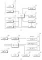
도 1 은 본 발명의 일실시예에 따른 가전기기를 포함하는 진단시스템의 구성이 도시된 구성도이다.1 is a configuration diagram showing a configuration of a diagnosis system including a home appliance according to an embodiment of the present invention.
도 1을 참조하면, 본 발명의 진단시스템은, 다수의 장소에 각각 개별 설치된 가전기기(1)와, 가전기기의 상태 및 고장을 진단하는 진단서버를 포함한다. 가전기기(1)는 조작부와 소정의 표시부와 신호음을 출력하는 음향출력부가 구비된다.Referring to FIG. 1, the diagnosis system of the present invention includes a
각 가정의 가전기기(1)에서 가전기기의 제품정보 또는 상태정보가 신호음으로 출력되면, 전화망을 통해 제품정보 및 상태정보가 포함된 소리신호가 서비스센터(200)의 진단서버로 전송되어, 가전기기의 상태에 대하여 고장여부를 진단하도록 구성된다.When product information or status information of household appliances is output from the
사용자는 가전기기(1)의 출력부에 표시되는 가전기기(1)의 제품정보를 확인하여, 가전기기(1)의 동작을 제어하거나, 서비스센터(200)에 수리를 요청하게 된다(S2).The user confirms the product information of the
사용자가 서비스 센터에 연결하여, 서비스 센터의 상담원의 요청에 따라(S3), 가전기기(1)에 구비되는 입력수단을 조작하는 경우, 가전기기(1)로부터 제품정보를 포함하는 신호음이 출력되어(S4), 서비스 센터로 신호음이 전송된다. 이때, 본원발명의 가전기기(1)는 제품정보를 단순 출력하지 않고, 제품정보를 변환하 여 소정의 신호음으로 출력하게 된다.When the user connects to the service center and operates the input means provided in the home appliance (1) at the request of the agent of the service center (S3), a signal sound containing the product information is outputted from the home appliance (1) (S4), a beep is transmitted to the service center. At this time, the home appliance (1) of the present invention converts the product information without outputting the product information, and outputs the product information with a predetermined signal.
즉, 사용자는 서비스센터(200)의 상담원과 통화 중(S2,S3), 전화기(81)를 가전기기(1)의 소리가 나는 곳에 가져다 댐으로써, 가전기기(1) 이상 발생 시 출력되는, 제품정보 또는 상태정보가 포함된 신호음(S1)이 전화망을 통해 서비스 센터로 전송된다(S4).That is, the user brings the
서비스센터의 상담원은 전화망을 통해 수신되는 가전기기의 소리신호가 진단서버에 저장되도록 한다. 진단서버는 신호음을 분석하여 가전기기(1)의 제품 상태와 고장여부를 진단한다(S5).The agent of the service center allows the sound signal of the household appliance received via the telephone network to be stored in the diagnosis server. The diagnostic server analyzes the signal tone to diagnose the product status and failure of the home appliance 1 (S5).
서비스 센터(200)는 진단결과에 대응하여, 가전기기(1)의 제품상태 및 고장진단에 적합한 서비스가 제공되도록 서비스 인원(93)을 가정에 파견하게 된다(S6). 이때, 진단 결과는 서비스 기사(93)의 단말로 전송되어(S6) 서비스 기사가 가전기기(1)의 고장을 수리할 수 있도록 하거나, 상담원을 통해 사용자에게 전달될 수 있다. 또한 진단결과는 사용자의 이메일로 전달되거나, 휴대단말로 전송 될 수 있다.In response to the diagnosis result, the
그에 따라, 진단시스템은 사용자가 서비스 센터에 소정의 통신망을 통해, 예를 들어 전화망을 통해 서비스센터에 연결하면, 가전기기(1)의 상태를 신호음을 통해 정확하게 판단하여 대처하게 되므로, 신속한 서비스가 가능하게 된다.Accordingly, when the user connects to the service center through the predetermined communication network, for example, through the telephone network, the diagnosis system accurately determines the state of the
이하, 본원발명의 가전기기(1)는 세탁물 처리기기인 것을 예로 하여 설명하나, 이에 한정되지 않고, tv, 에어컨, 세탁기, 냉장고, 전기밥솥, 전자레인지 등과 같은 가전기기(1) 전반에 적용될 수 있음을 명시한다.Hereinafter, the home
이러한, 가전기기(1)는 다음과 같이 구성되어, 제품정보를 소정의 신호음으 로 출력하고, 진단서버는 가전기기(1)의 상태 및 고장여부를 진단한다.The home appliance (1) is configured as follows, and outputs the product information with a predetermined beep, and the diagnosis server diagnoses the state and failure of the home appliance (1).
도 2 는 본 발명의 일실시예에 따른 가전기기 및 가전기기와 서비스센터의 관계에 대한 구성이 도시된 도이다.FIG. 2 is a diagram illustrating a configuration of a home appliance, a home appliance, and a service center according to an exemplary embodiment of the present invention. Referring to FIG.
가전기기의 일 실시예로서 세탁물 처리기기를 중심으로 설명하면 다음과 같다. 도 2의 (a)를 참조하면, 세탁물 처리기기(1)는 캐비닛(111)과, 캐비닛(111) 내부에 배치되며 세탁물의 세정이 이루어지는 터브(122)와, 터브(122)를 구동시키는 모터(미도시)와, 터브(122)의 세탁수를 공급하는 세탁수 공급장치(미도시)와, 세정이 끝난 후에 세탁수를 외부로 배출하는 배수장치(미도시)를 포함한다.As an example of the household appliance, a laundry processing apparatus will be mainly described as follows. Referring to FIG. 2A, the
캐비닛(111)은, 캐비닛 본체(112)와, 캐비닛 본체(112)의 상측에 배치되어 결합하는 캐비닛 커버(113)와, 캐비닛 커버(114) 상측에 배치되며 세탁물 처리기기(1)의 운전을 제어하는 컨트롤패널(116)과, 컨트롤패널(116) 상측에 배치되며 캐비닛 본체(112)와 결합하는 탑 플레이트(115)를 포함한다. 캐비닛 커버(113)는 세탁물이 출입하는 홀(미도시)과, 상기 홀을 개폐 가능하도록 회동하는 도어(114)를 포함한다.The
컨트롤패널(116)은, 세탁물 처리기기(1)의 운전을 조작하는 복수의 조작키(117)가 컨트롤패널(116)에 배치되며 세탁물 처리기기(1)의 운전 상태를 신호음으로 출력하는 음향출력부(72)와, 상기 운전 상태를 화상으로 표시하는 표시부(71)를 포함한다.The
도 2의 (b)를 참조하면, 상기와 같은 세탁물 처리기기(1)에 이상이 발생되면, 그에 대한 정보가 표시부(71)에 출력되거나, 소정의 경고음이 출력된다. 그에 따라 사용자는 세탁물 처리기기(1) 이상 시, 서비스 센터(200)에 연결하는데, 이때, 서비스 센터의 요청에 따라, 사용자가 조작부(22)를 조작하게 된다.Referring to FIG. 2 (b), when an abnormality occurs in the
상기와 같은 세탁물 처리기기(1)는 사용자가 조작부(22)를 누름조작함에 따라, 신호 출력명령이 입력되어 변환부(60)를 통해 제품정보를 음향신호로 변환하고, 음향신호를 음향출력부(72)를 통해 소정의 신호음으로 출력한다.As the user depresses the
이때, 음향출력부(72)를 통해 출력된 신호음(100)은 소정의 통신망에 연결된 단말기(81)를 통해 서비스 센터(90)로 전달된다. 이때, 통신망은 전화망 또는 휴대 이동통신 망인 것을 예로 하며, 단말기(81)는 전화기, 이동단말이 사용되는 것을 예로 하여 설명한다.At this time, the
서비스 센터(90)는 이를 분석하여 가전기기(1)의 운전정보와 고장정보를 획득한다. 그에 따라 서비스 센터는 가전기기(1)의 오동작에 따른 대처방안을 사용자에게 전달하거나, 서비스 인원을 파견하게 된다.The service center 90 analyzes this to obtain the operation information and the failure information of the home appliance (1). Accordingly, the service center transmits the countermeasures corresponding to the malfunction of the home appliance (1) to the user or dispatches the service personnel.
도 3 은 본 발명의 일실시예에 따른 가전기기 및 진단서버의 구성이 도시된 블록도이다. 도 3의 (a)는 세탁물 처리기기(1)의 구성이 도시된 블록도이고, 도 3의 (b)는 서비스 센터의 진단서버의 구성이 도시된 블록도이다.3 is a block diagram illustrating a configuration of a home appliance and a diagnosis server according to an embodiment of the present invention. 3 (a) is a block diagram showing the configuration of the
전술한 바와 같이 구성된 세탁물 처리기기(1)는 다음과 같은 제어구성을 더 포함하여 동작된다. 도 3의 (a)를 참조하면, 세탁물 처리기기(1)는 입력부(21), 조작부(22), 감지부(30), 구동부(40), 저장부(50), 변환부(60), 출력부(70), 그리고 기기 동작 전반을 제어하는 제어부(10)를 포함한다. 여기서 출력부(70)는 표시부(71), 음향출력부(72)를 포함한다.The
구동부(40)는 제어부(10)로부터 인가되는 제어신호에 대응하여, 소정 동작을 수행하도록 그 구동을 제어한다. 세탁물 처리기기의 경우, 구동부(40)는 세탁조 또는 드럼이 회전하여 세탁물의 오물이 제거되도록, 세탁조 또는 드럼을 회전시키는 모터를 구동하고 그 동작을 제어한다. 또한, 구동부(40)는 제어부(10)의 제어신호에 대응하여, 급수 또는 배수가 수행되도록 밸브를 제어하게 된다.The
감지부(30)는 적어도 하나의 센서를 포함하여, 상기와 같이 구동부(40)에 의해 세탁물 처리기기(1)가 소정의 동작을 수행하는 때, 세탁물 처리기기(1)의 동작상태 확인을 위한 데이터를 측정하여 제어부(10)로 인가한다.The
저장부(50)는 상기와 같이 세탁물 처리기기(1)가 소정의 동작을 수행하는 중, 동작 중 발생되는 동작상태 데이터, 세탁물 처리기기(1)가 소정 동작을 수행하도록 입력부(21)에 의해 입력된 설정데이터와 같은 운전정보와, 세탁물 처리기기(1) 오동작 시, 오동작의 원인 또는 오동작 부위에 대한 정보를 포함하는 고장정보가 저장된다.The
또한, 저장부(50)는 세탁물 처리기기(1)의 동작을 제어하기 위한 제어데이터, 동작제어 시 사용되는 기준데이터가 저장된다. 저장부(50)에는 감지부(30)에 구비된 센서의 상태 및 각 센서의 측정데이터도 저장된다.In addition, the
조작부(22)는 적어도 하나의 입력수단을 포함하여, 제품정보가 음향출력부(72)를 통해 소정의 신호음으로 출력되도록 하는 신호 출력명령을 입력받아, 제어부(10)로 인가한다. 또한, 조작부(22)는 신호 출력명령을 입력받아, 음향출력부(72)가 온, 오프(on/off)되도록 한다. 즉, 조작부(22)에 의해 신호 출력명령이 입력되면, 제어부(10)의 제어신호에 대응하여, 제품정보가 소정의 신호음으로 출력되는데, 이때, 음향출력부(72)가 동작되어, 신호음을 출력하게 된다.The
입력부(21)는 입력수단으로써, 신호음 출력에 따른 설정을 입력받는다. 즉, 입력부(21)는 신호음을 출력하는 방법, 출력되는 신호음의 크기 등을 설정하는 설정값을 입력받는다.The
이때, 조작부(22) 및 입력부(21)와 같은 입력수단(20)은 버튼, 돔 스위치(dome switch), 터치 패드(정압/정전), 조그 휠, 조그 스위치, 핑거 마우스, 로터리 스위치, 조그 다이얼 등으로 구성될 수 있으며, 조작에 의해 소정의 입력데이터를 발생하는 장치라면 어느 것이나 적용 가능하다.At this time, the input means 20 such as the operating
제어부(10)는 조작부(22)로부터 신호 출력명령이 입력되면, 저장부(50)에 저장된 제품정보를 호출하여 변환부(60)로 인가하고, 변환부(60)가 제품정보를 소정의 음향신호로 변환하도록 하는 제어신호를 발령한다. 또한, 제어부(10)는 조작부(22)의 신호 출력명령이 입력됨에 따라, 음향출력부(72)가 동작 되도록 제어한다.The
여기서, 제품정보는 전술한 바와 같이, 운전설정, 동작중 운전상태 등을 포함하는 운전정보와, 오동작에 대한 고장정보를 포함한다. 제품정보는 0 또는 1의 조합으로 이루어진 데이터로서, 제어부(10)에 의해 판독 가능한 형태의 디지털 신호이다.Here, as described above, the product information includes the operation information including the operation setting, the operation state during operation, and the malfunction information. The product information is data consisting of a combination of 0 or 1 and is a digital signal readable by the
변환부(60)는 제어부(10)의 제어신호에 대응하여, 저장부(50)의 제품정보를, 신호음 출력을 위한 소정의 음향신호로 변환한다. 여기서 변환부(60)는 디지털 신 호인 제품정보를 소정 주파수 대역의 아날로그신호로 변환하는데, 신호 변환 시, 주파수 편이 방식, 진폭편이방식, 위상편이방식 중 어느 하나의 방식을 이용하여, 제품정보를 음향신호로 변환한다.The converting
여기서, 주파수 편이방식은 제품정보의 데이터 값에 대응하여 소정 주파수의 신호로 변환하는 방식이고, 진폭편이 방식은 데이터 값에 대응하여 진폭의 크기가 상이하도록 변환하는 방식이다. 또한, 위상편이방식은 제품정보의 데이터값에 따라 위상이 상이하도록 신호를 변환하는 방식이다.Here, the frequency shift method is a method of converting into a signal of a predetermined frequency corresponding to the data value of the product information, and the amplitude shift method is a method of converting the amplitude so as to correspond to the data value. The phase shift method is a method of converting a signal so that the phases are different according to the data value of the product information.
변환부(60)는 상기와 같은 방식에 따라 소정 주파수 대역의 신호로 제품정보를 변환하고, 각각 변환된 신호를 조합하여 음향신호를 출력한다.The converting
이때, 출력되는 신호음은 제품정보 뿐 아니라, 제품정보가 포함된 데이터의 시작을 알리는 프리앰블이 데이터의 앞부분에 추가되고, 데이터에는 제품정보 이외에도 데이터의 에러체크를 위한 체크비트가 포함된다. 가전기기의 제품정보를 음향신호를 출력하는데, 복수의 프레임으로 구분되어 각 프레임별로 프리앰블이 삽입된다.At this time, a preamble indicating the start of the data including the product information is added to the output signal of the product as well as the product information, and the data includes a check bit for error checking of the data in addition to the product information. The product information of the home appliance is outputted as an acoustic signal. The preamble is divided into a plurality of frames and a preamble is inserted for each frame.
음향출력부(72)는 제어부(10)의 제어신호에 의해 동작이 온, 오프 되며, 변환부(60)로부터 출력된 음향신호를 입력받아 소정의 신호음을 출력한다. 이때, 음향출력부(72)는 스피커, 버저 등과 같이 소리를 출력하는 수단이 사용될 수 있다.The
음향출력부(72)는 음향신호를 신호음으로 출력한 후, 출력이 종료되면, 동작 정지되고, 조작부(22)에 의해 신호 출력명령이 입력되는 경우, 다시 동작되어 소정의 신호음을 출력한다.The
표시부(71)의 제어부(10)의 제어신호에 대응하여, 조작부(22) 및 입력부(21)에 의해 입력되는 정보, 세탁물 처리기기(1)의 동작상태 정보, 가전기기 동작완료 등에 따른 정보를 화면에 표시한다. 또한, 가전기기 오동작시 오동작에 관한 고장정보를 화면에 표시한다.Information input by the
이때, 출력부(70)는 상기와 같은 음향 출력부(72), 표시부(71) 이외에도 점등 또는 점멸되는 램프, 진동소자 등이 더 포함될 수 는 있으나, 그에 대한 설명은 하기에서 생략하기로 한다.In this case, the
상기와 같이 구성되는 세탁물 처리기기(1)는 소정의 신호음을 출력하여, 다음 설명하는 바와 같이, 서비스 센터(200)로 세탁물 처리기기(1)의 제품정보를 전달하게 된다.The
세탁물 처리기기(1)의 제품정보가 신호음으로 출력되어 전화망 등을 통해 서비스 센터(200)로 전송되면, 이는 서비스센서(200)에 구비된 진단서버로 입력되어 세탁물 처리기기(1)에 대한 고장 진단을 수행한다.When the product information of the
이러한 진단서버는 도 3의 (b)에 도시된 바와 같이, 통신부(220), 신호변환부(230), 데이터부(240), 입출력부(270), 신호검출부(250), 클럭생성부(280), 진단부(260), 그리고 서버의 동작전반을 제어하는 메인제어부(210)를 포함한다.3 (b), the diagnosis server includes a
입출력부(270)는 서비스 센터(90)의 사용자에 의해 조작되는 버튼, 키, 터치패드, 스위치와 같은 입력수단을 포함하고, 진단서버의 동작 정보 및 진단결과가 출력되는 표시수단 이 포함된다. 또한, 입출력부(270)는 외부입력장치, 휴대용 메모리 수단에 대한 접속 인터페이스를 포함한다.The input /
입출력부(270)는 입력수단이 조작되는 경우, 메인제어부(210)로 신호를 인가하여, 전화망을 통해 연결된 사용자의 전화기 또는 휴대단말로부터, 세탁물 처리기기의 신호음이 진단서버로 수신되도록 한다.When the input means is operated, the input /
통신부(220)는 서비스 센터의 전산망과 연결되어 데이터를 송수신하고, 인터넷과 같은 외부 네트워크에 연결되어 통신한다. 특히, 통신부(220)는 메인제어부(210)의 제어명령에 대응하여, 입력수단 조작을 통해 녹음명령 또는 수신명령 입력 시, 전화망을 통해 신호음 데이터를 수신하고, 진단 결과를 외부로 전송한다.The
데이터부(240)에는 진단서버 동작을 위한 제어데이터와, 세탁물 처리기기 등의 가전기기로부터 수신된 신호음 데이터가 비트스트림 데이터(242)로 저장되고, 신호음 데이터로부터 가전기기의 제품정보를 검출하기 위한 기준데이터(241), 고장 여부 및 고장원인을 진단하기 위한 진단데이터(243)가 저장된다.In the
여기서, 데이터부(240)는 메인제어부(210)에 의해, 기준데이터(241), 비트스트림 데이터(242), 진단데이터(243) 가전기기데이터(244)가 입력 및 관리되고, 갱신된다.Here, in the
신호변환부(230)는 수신되는 아날로그의 신호음 데이터를 변환하여 비트스트림 데이터(24)를 저장한다. 이때, 신호변환부(230)에서의 신호 변환은 가전기기(1)에서의 신호 변환에 대한 역 변환으로써, 각 가전기기와 진단서버는 상호 협약을 통해 동일한 신호 변환 체계를 통해 데이터를 변환하는 것이 바람직하다. 신호변환부(230)는 소정 주파수 대역의 아날로그 신호인 신호음을, 주파수 편이 방식, 진폭편이방식, 위상편이방식 중 어느 하나를 이용한 역변환을 통해 디지털 신호로 변환 한다.The
신호검출부(250)는 신호변환부(230)에 의해 변환된 비트스트림으로부터, 데이터의 시작을 알리는 프리앰블을 우선 검출하고, 검출된 프리앰블을 기준으로 제품정보가 포함된 데이터를 검출하여 가전기기 데이터(244)로 데이터부(240)에 저장한다. 신호검출부(250)는 기준데이터(241)에 포함된 프리앰블의 크기와, 데이터의 크기에 대한 기준데이터(242)에 근거하여, 프리앰블 및 데이터를 검출한다.The
신호검출부(250)는 프리앰블로 추정되는 신호가 검출되면, 클럭생성부(280)로 클럭생성명령을 인가하고, 클럭생성부(280)에 의해 생성된 심볼클럭을 이용하여 기 설정된 프리앰블 및 데이터의 크기에 대응하여 프리앰블과 데이터를 검출한다.When a signal estimated as a preamble is detected, the
신호검출부(250)는 클럭생성부(280)에서 소정의 단위시간 간격으로 복수의 심볼 클럭이 생성되도록 하며, 생성된 복수의 심볼 클럭을 동기신호로 하여, 비트스트림으로부터 각각의 심볼 클럭에 대응하는 프리앰블과 데이터를 검출한다.The
신호검출부(250)는 검출된 데이터에 포함된 체크비트를 이용하여 복수의 데이터에대한 에러체크를 수행하고, 복수의 심볼 클럭에 따른 복수의 데이터로부터 정상 데이터를 검출하고, 에러가 발생된 데이터는 폐기한다.The
이때, 신호검출부(250)는 후술하는 도 4 와 같이 프리앰블로 인식한 포스트 프리앰블1이 끝나는 시점에서 클럭생성명령을 클럭생성부(280)로 인가하고, 포스트 프리앰블 2가 종료되는 시점에서 클럭생성명령을 클럭생성부(280)로 인가한다.At this time, the
클럭생성부(280)는 신호검출부(250)의 클럭생성명령이 입력되면, 그에 대응하여 소정의 단위시간 간격으로 심볼클럭을 생성한다. 이때, 클럭생성부(280)는 한 번의 클럭생성명령에 대응하여 0.5 msec 단위로 심볼클럭을 9개 생성한다. 이때, 심볼클럭 생성 주기 및 심볼클럭의 수는 설정에 따라 변경될 수 있다.When a clock generation command of the
신호검출부(280)는 하나의 프리앰블을 검출하기 위해 두 번의 클럭생성명령을 클럭생성부(280)로 인가하여 9개씩 2회, 총 18개의 심볼클럭을 각각 동기화 신호로 이용함으로써, 신호음의 비트스트림으로부터 프리앰블 및 데이터를 검출한다.In order to detect one preamble, the
진단부(260)는 신호검출부(250)에 의해 검출된 데이터를 분석하고, 데이터에 포함된 제품정보를 이용하여 가전기기(1)의 상태 및 고장여부를 판단하고, 고장의 원인에 대하 분석하여 진단결과를 출력한다. 이때, 진단부(260)는 진단데이터(243)에 포함된 진단알고리즘 및 진단에 따른 기준값을 이용하여 진단한다.The
메인제어부(210)는 통신부(220)를 통한 데이터의 송수신 및 입출력부(270)를 통해 데이터의 흐름을 제어하고, 가전기기의 제품정보가 포함된 신호음이 신호변환부(230)에 의해 변환 처리되고, 신호검출부(250)를 통해 데이터가 검출되도록 그 동작을 제어한다.The
또한, 메인제어부(210)는 검출된 데이터를 이용하여 진단부(260)에서 가전기기의 대한 고장 진단을 수행하도록 각 부로 제어명령을 인가한다. 메인제어부(210)는 진단부(260)의 진단결과를 입출력부(270)를 통해 출력되도록 하거나, 통신부(220)를 통해 전송되도록 제어한다.In addition, the
도 4 는 본 발명의 일실시예에 따른 진단서버의 심볼클럭을 이용한 프리앰블 및 데이터 검출의 예가 도시된 도이다.4 is a diagram illustrating an example of preamble and data detection using a symbol clock of a diagnostic server according to an embodiment of the present invention.
도 4를 참조하면, 가전기기(1)는 신호음을 출력하고, 출력된 신호음을 전화 망등을 통해 서비스 센터의 진단서버로 수신된다. 진단서버는 신호음을 변환하여 비트스트림으로 데이터부(240)에 저장하고, 신호검출부(250)는 비트스트림으로부터 프리앰블 및 데이터를 검출한다.Referring to FIG. 4, the
이때, 비트스트림은 노이즈, 프리앰블(303, 306), 데이터(304, 307)를 포함하며 각 프리앰블과 데이터는 하나의 프레임(C)을 형성하고, 프레임과 프레임 사이는 IFS(305)가 포함된다.At this time, the bit stream includes noise,
각 프레임의 개별 데이터는 가전기기의 제품정보의 일부를 포함하고, 복수의 데이터가 모여 가전기기 진단을 위한 제품정보가 된다. 진단부(260)는 가전기기의 고장진단을 위한 데이터가 모두 검출되면, 데이터에 포함된 제품정보를 분석하여 고장 진단을 수행한다.The individual data of each frame includes a part of the product information of the household electric appliance, and a plurality of data are gathered to become the product information for the household appliance diagnosis. The
신호검출부(250)는 프리앰블로 추정되는 포스트 프리앰블(301)이 인식되면, 기 설정된 프리앰블의 크기(A)에 따라 포스트 프리앰블1이 끝나는 제 1 시간(T1)에 클럭생성명령을 클럭생성부(280)로 인가하고, 다음 프리앰블로 추정되는 포스트프리앰블2(302)가 인식되면, 포스트프리앰블2(302)가 끝나는 시점인 제 2 시간(T2)에 클럭생성명령을 클럭생성부(280)로 인가한다.When the
그에 따라 클럭생성부(280)는 소정의 단위시간 간격으로 복수의 심볼 클럭을 생성하는데, 제 1 시간(T1)을 기준으로 소정의 단위시간(308) 간격으로 9개의 심볼클럭을 생성하고(291), 제 2 시간(T2)을 기준으로 9개의 심볼클럭을 생성한다(292). 이때 심볼클럭을 생성하는 단위시간은 0.5msec인 것을 예로 하여 설명하며, 심볼클럭의 생성 시간 단위는 심볼의 크기에 따라 변경될 수 있다.The
이때, 신호검출부(250)는 초기에 프리앰블의 정확히 검출하지 못하고 실제 프리앰블이 아닌 포스트 프리앰블1,2를 프리앰블로 인식하더라도, 포스트프리앰블1,2(301,302)를 인식함으로써, 제 1 시간(T1)부터 발생된 9개의 심볼클럭과, 제 2 시간(T2)부터 생성된 9개의 심볼클럭(292), 총 18개의 심볼클럭을 이용하여, 각각의 심볼클럭을 동기신호로 하여, 비트스트림으로부터 데이터 후보를 추출할 수 있다.At this time, even if the
즉, 신호검출부(250)는 시간차를 갖는 다중 심볼클럭에 의해 18개의 후보를 추출함으로써 후보로부터 데이터와 프리앰블을 검출한다.That is, the
이때, 각 후보는 프리앰블 크기(A)와 데이터의 크기(B)에 대응하여 추출한다.At this time, each candidate is extracted corresponding to the preamble size (A) and the data size (B).
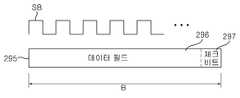
도 5 는 도 4의 심볼클럭을 이용한 데이터 검출의 예가 도시된 도이다.5 is a diagram showing an example of data detection using the symbol clock of FIG.
전술한 도 4에서 심볼클럭을 동기신호로 하여 복수의 데이터 후보가 도 5에 도시된 바와 같이 검출된다. 프리앰블이 끝나는 시점으 기준으로 하므로 데이터 후부가 추출된다.In Fig. 4, a plurality of data candidates are detected as shown in Fig. 5 with the symbol clock as a synchronization signal. Since the reference is based on the end of the preamble, the data rear portion is extracted.
하나의 심볼클럭(SB)에 대한 데이터 후보(295)는 데이터 크기(B)에 따라 추출되고, 내부에 제품정보가 포함된 데이터 필드(296)와 에러 체크를 위한 체크비트(297)로 구성된다.The
신호검출부(250)는 18개의 심볼클럭(291, 292, SB)에 대한 18개의 데이터 후보를 도 5와 같이 검출하고, 각 데이터 후보에 포함된 체크비트(297)를 이용하여 데이터의 오류여부를 체크한다.The
여기서, 신호검출부250)는 18개의 심볼클럭을 동기신호로 하여 추출된 18개의 데이터 후보 중 체크비트(297)을 이용한 에러체크에서 정상으로 확인된 데이터후보를 정상 데이터로써 검출한다. 신호검출부(250)는 정상 데이터(304)가 검출되면, 이를 역 이용하여 프리앰블(303)을 추출할 수 있다.Here, the
이때, 후보 18개 중 17개는 정상적으로 시작된 데이터가 아니므로, 체크비트에서 에러로 확인될 뿐 아니라, 체크비트조차 에러가 있을 수 있다. 예를 들어 '01110'의 프리앰블과 '101010111......'의 데이터를 각 심볼클럭에 따라 인식하므로 추출된 후보 18개는 모두 상이하고, 그중 정확하게 01110의 프리앰블과 ''101010111......'의 데이터와 일치하는 것은 하나만 존재하게 된다.At this time, since 17 out of 18 candidates are not normally started data, not only an error is confirmed in a check bit, but even a check bit may be an error. For example, since the preamble of '01110' and the data of '101010111 · ·' are recognized according to each symbol clock, all 18 extracted candidates are different, and the preamble of 01110 and '101010111 ...' ... ", there is only one match.
신호검출부(250)는 다음 프리앰블(306) 및 데이터(307)에 대해서도 시간차를 갖는 다중 심볼클럭을 이용하여, 검출한다.The
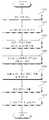
도 6 은 본 발명의 진단서버의 프리앰블 검출방법이 간략하게 도시된 순서도이다.6 is a flowchart showing a preamble detection method of the diagnosis server of the present invention.
진단서버는 서비스센터로부터 진단 요청 및 신호음 데이터를 수신한다(S4310). 이때 신호변환부(230)는 소리신호인 신호음을 변환하여 데이터부(240)에 비트스트림 데이터(243)로 저장한다(S320).The diagnostic server receives the diagnostic request and the beep data from the service center (S4310). At this time, the
신호검출부(250)는 비트스트림으로부터 프리앰블로 추정되는 신호가 인식되면, 기 설정된 프리앰블의 크기(A)에 대응하여 해당 신호를 포스트 프리앰블로 검출하고(S340), 포스트 프리앰블이 끝나는 시점을 기준으로 클럭생성명령을 클럭생성부(280)로 입력한다.When a signal estimated as a preamble is recognized from the bitstream, the
그에 따라 클럭생성부(280)는 소정의 단위시간 간격으로 복수의 심볼클럭을 생성한다.Accordingly, the
신호검출부(250)는 프리앰블로 추정되는 다른 신호가 검출되면, 포스트 프리앰블 2로 검출하여 상기와 같이 심볼클럭이 생성되도록 클럭생성부(280)로 클럭생성명령을 인가한다.When another signal estimated as a preamble is detected, the
신호검출부(250)는 일정 시간 차를 갖는 다중 심볼클럭을 각각을 비트스트림에 대한 동기신호로 이용하여 하나의 심볼클럭 당 하나의 데이터 후보를 생성하고, 생성된 복수의 데이터 후보에 대하여 체크비트를 이용한 에러체크를 수행한다(S350).The
복수의 데이터 후보 중 정상 데이터로 인식된 하나의 데이터 후보를 데이터로써 검출하고, 그에 따라 프리앰블을 검출한다(S360). 이때, 정상으로 인식된 데이터 후보에 대한 심볼클럭을 해당 프레임 동안의 기준 심볼클럭으로 설정할 수 있다. 비정상의 나머지 데이터 후보는 페기한다.One data candidate recognized as normal data among a plurality of data candidates is detected as data, and a preamble is detected (S360). At this time, the symbol clock for the data candidate recognized as normal can be set as the reference symbol clock for the corresponding frame. The remaining data candidates are discarded.
진단을 위한 모든 데이터가 검출되면, 진단부(260)는 데이터 분석을 통해 제품정보에 따른 고장 진단을 수행한다(S370).When all the data for diagnosis are detected, the
메인제어부(210)는 진단부(260)의 진단결과를 통신부(220)를 통해 전송하거나, 입출력부(270)를 통해 출력되도록 한다. 이때, 진단서버는 진단결과를 서비스 인원의 단말로 전송하거나, 입출력부(270)로 출력한다.The
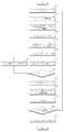
도 7 은 도 6의 진단서버의 심볼클럭을 이용한 프리앰블 및 데이터의 검출방법이 도시된 순서도이다.7 is a flowchart showing a method of detecting a preamble and data using a symbol clock of the diagnosis server of FIG.
도 7 을 참조하면, 신호검출부(250)는 입력되는 비트스트림(S410), 프리앰블로 추정되는 신호를 인식하여 제 1 포스트 프리앰블을 검출한다(S420).Referring to FIG. 7, the
프리앰블의 크기는 미리 정의 되어 있으므로, 신호검출부(250)는 제 1 포스트 프리앰블(301)이 끝나는 시점에서 클럭생성명령을 클럭생성부(280)로 인가한다. 그에 따라 클럭생성부(280)는 시간차를 같는 복수의 심볼클럭을 생성한다(S430).Since the size of the preamble is defined in advance, the
또한, 신호검출부(250)는 제 1 포스트 프리앰블(301) 이후 프리앰블로 추정되는 신호를 인식하여 제2 포스트 프리앰블(302)을 검출한다(S440). 신호검출부(250)는 , 제 2 포스트 프리앰블(302)이 끝나는 시점에서 클럭생성명령을 클럭생성부(280)로 인가하고, 그에 따라 클럭생성부(280)는 시간차가 있는 복수의 심볼클럭을 생성한다(S450).In operation S440, the
여기서, 클럭생성부(280)는 신호검출부(250)의 클럭생성명령에 대응하여, 전술한 도 4에서와 같이 제 1 포스트 프리앰블(301)이 끝나는 시점이 제 1 시간(T1)부터 단위시간 0.5 msec 간격으로 9개의 심볼클럭을 생성하고, 제 2 포스트 프리앰블(302)가 끝나는 시점인 제 2 시간(T2)부터 0.5 msec 간격으로 9개의 심볼클럭을 생성하여, 시간차가 있는 18개의 심볼클럭을 생성한다.In this case, the
이때, 단위시간 및 심볼클럭의 수는 하나의 정보를 나타내는 심볼의 크기 및 데이터의 크기에 따라 가변될 수 있다. 심볼클럭의 수가 증가되면 그에 따른 처리속도가 느려지나, 심볼클럭의 수가 감소되면, 데이터 검출 확률이 낮아지므로 이를 고려하여, 심볼의 크기와 데이터의 크기에 따라 단위시간과 심볼클럭의 수를 설정하는 것이 바람직하다.In this case, the unit time and the number of symbol clocks may vary according to the size of the symbol representing one information and the size of the data. If the number of symbol clocks is increased, the processing speed is slowed down. However, if the number of symbol clocks is decreased, the data detection probability is lowered. Therefore, the unit time and the number of symbol clocks are set according to the size of the symbol and the data size .
신호검출부(250)는 시간차가 있는 다중 심볼클럭을 동기신호로 이용하여 비트스트림으로부터 데이터를 추출한다(S460). 이때, 심볼클럭은 포스트 프리앰블이 끝나는 시점을 기준으로 하므로 신호검출부(250)는 심볼클럭 각각에 대하여 데이터 후보를 추출하게 된다.The
심볼클럭이 제 1 시간과 제 2 시간을 기준으로 총 18개가 생성되고, 이를 이용하므로, 데이터 후보도 18개가 추출된다. 신호검출부(250)는 각 데이터 후보에 대하여 데이터에 포함된 체크비트(297)를 이용하여 에러를 체크한다(S480).A total of 18 symbol clocks are generated based on the first time and the second time, and therefore 18 data candidates are extracted. The
각 데이터후보를 대상으로 에러 여부를 판단하고(S490), 에러가 있는 데이터 후보는 폐기하고 다음 심볼클럭에 대한 데이터 후보를 확인한다(S500). 신호검출부(250)는 심볼클럭에 의해 추출된 모든 데이터 후보에 대하여 상기와 같이 체크비트를 이용한 에러체크를 수행한다(S480, S490).An error is determined for each data candidate (S490), the data candidate having an error is discarded and a data candidate for the next symbol clock is confirmed (S500). The
이때, 데이터는 데이터의 마지막에 일정한 크기로 체크비트를 포함하므로, 이를 이용하여 추출된 데이터 후보가 정상데이터 인 것으로 추정하여. 데이터의 크기 및 체크비트의 크기에 따라 체크비트를 확인하고, 체크비트를 이용한 데이터의 에러체크를 수행한다.At this time, since the data includes a check bit at a predetermined size at the end of the data, it is estimated that the extracted data candidate is normal data. Checks the check bit according to the size of the data and the size of the check bit, and performs error check of the data using the check bit.
복수의 데이터 후보 중 실제 데이터는 단 하나 존재하고 나머지 데이터는 정상적인 데이터가 아니므로, 하나의 데이터 후보 만이 정상적인 체크비트를 포함하고, 정상데이터로 확인된다.Since there is only one actual data among the plurality of data candidates and the remaining data is not normal data, only one data candidate includes a normal check bit and is confirmed as normal data.
신호검출부(250)는 정상인 것으로 판단된 데이터 후보를 정상 데이터로 설정하고(S510) 정상 데이터의 심볼클럭 또는 데이터를 기준으로 역으로 프리앰블을 추 출할 수 있다(S520). 이때, 정상 데이터의 심볼클럭은 해당 프레임 내에서 기준클럭으로 사용될 수 있다.The
신호검출부(250)는 검출된 데이터를 데이터부(240)에 저장하고, 진단부(260)는 데이터를 분석하여 제품정보를 확인한다(S53).The
이때, 진단에 필요한 모든 데이터가 수집되기까지(S540) 상기와 같이 시간차가 있는 다중 심볼클럭을 이용한 데이터 검출은 반복하여 수행된다(S410 내지 540).At this time, the data detection using the multi-symbol clock having the time difference as described above is repeatedly performed (S410 to S540) until all data necessary for diagnosis are collected (S540).
진단부(260)는 각 데이터(295)의 데이터필드(296)에 포함된 제품정보를 이용하여 가전기기의 상태, 고장여부, 고장원인에 대하여 진단하여 진단결과를 생성하고 , 메인제어부(210)는 전술한 바와 같이 진단결과를 입출력부(270)를 통해 출력하거나, 서비스 인원(96)의 단말로 전송한다.The
그에 따라 사용자는 서비스센터로부터 진단결과를 통보 받아 자가 대처 하거나, 서비스 인원의 파견으로 가전기기의 이상을 수리하게 된다. 가정을 방문하는 서비스 인원은 진단결과를 수신하여 이를 바탕으로 가전기기의 상태를 점검하고 수리하게 된다.Accordingly, the user is informed of the diagnosis result from the service center, or the service provider dispatches the service person to repair the abnormality of the home appliance. The service personnel who visit the home receive the diagnosis result and check the condition of the home appliance and repair it.
따라서 본 발명에 따른 가전기기 진단시스템 및 그 진단방법은 시간차가 있는 복수의 심볼클럭을 생성하고, 심볼클럭을 이용하여 데이터를 추출하여 에러체크를 통해 데이터를 검출함으로써, 데이터를 효과적으로 검출할 수 있고 검출된 데이터의 정확도도 향상되므로 그에 따라 정확한 진단이 가능하게 된다.Therefore, the household appliance diagnosis system and the diagnosis method according to the present invention can generate a plurality of symbol clocks having a time difference, extract data using a symbol clock, detect data through error checking, The accuracy of the detected data is improved, so that accurate diagnosis can be performed.
이상과 같이 본 발명에 의한 가전기기 진단시스템 및 그 진단방법을 예시된 도면을 참조로 설명하였으나, 본 명세서에 개시된 실시예와 도면에 의해 본 발명은Although the present invention has been described with reference to exemplary embodiments thereof, it is to be understood that the invention is not limited to the disclosed exemplary embodiments,
한정되지 않고, 기술사상이 보호되는 범위 이내에서 응용될 수 있다.And can be applied within a range in which technical ideas are protected.
도 1 은 본 발명의 일실시예에 따른 가전기기를 포함하는 진단시스템의 구성이 도시된 구성도,1 is a configuration diagram showing a configuration of a diagnostic system including a home appliance according to an embodiment of the present invention;
도 2 는 본 발명의 일실시예에 따른 가전기기 및 가전기기와 서비스센터의 관계에 대한 구성이 도시된 도,FIG. 2 is a diagram illustrating a configuration of a home appliance according to an exemplary embodiment of the present invention, a configuration of a relationship between a home appliance and a service center,
도 3 은 본 발명의 일실시예에 따른 가전기기 및 진단서버의 구성이 도시된 블록도,3 is a block diagram illustrating a configuration of a home appliance and a diagnosis server according to an embodiment of the present invention.
도 4 는 본 발명의 일실시예에 따른 진단서버의 심볼클럭을 이용한 프리앰블 및 데이터 검출의 예가 도시된 도,4 is a diagram illustrating an example of preamble and data detection using a symbol clock of a diagnostic server according to an embodiment of the present invention;
도 5 는 도 4의 심볼클럭을 이용한 데이터 검출의 예가 도시된 도,5 is a diagram showing an example of data detection using the symbol clock of FIG. 4,
도 6 은 본 발명의 진단서버의 프리앰블 검출방법이 간략하게 도시된 순서도,6 is a flow chart schematically showing a preamble detection method of the diagnostic server of the present invention;
도 7 은 도 6의 진단서버의 심볼클럭을 이용한 프리앰블 및 데이터의 검출방법이 도시된 순서도이다.7 is a flowchart showing a method of detecting a preamble and data using a symbol clock of the diagnosis server of FIG.
<도면의 주요 부분에 관한 부호의 설명>DESCRIPTION OF THE REFERENCE NUMERALS
1: 가전기기 22: 조작부1: home appliance 22:
60: 변환부 72: 음향출력부60: conversion section 72: sound output section
100: 신호음 200: 서비스센터/진단서버100: Beep 200: Service center / diagnosis server
250: 심호검출부 260: 진단부250: Simulation detection unit 260: Diagnosis unit
280: 클럭생성부280: clock generator
Claims (15)
Translated fromKoreanPriority Applications (2)
| Application Number | Priority Date | Filing Date | Title |
|---|---|---|---|
| KR1020090031501AKR101421685B1 (en) | 2009-04-10 | 2009-04-10 | Home appliance diagnosis system and its diagnosis method |
| US12/757,232US8615380B2 (en) | 2009-04-10 | 2010-04-09 | System and method for diagnosing home appliance |
Applications Claiming Priority (1)
| Application Number | Priority Date | Filing Date | Title |
|---|---|---|---|
| KR1020090031501AKR101421685B1 (en) | 2009-04-10 | 2009-04-10 | Home appliance diagnosis system and its diagnosis method |
Publications (2)
| Publication Number | Publication Date |
|---|---|
| KR20100112950A KR20100112950A (en) | 2010-10-20 |
| KR101421685B1true KR101421685B1 (en) | 2014-08-13 |
Family
ID=42935299
Family Applications (1)
| Application Number | Title | Priority Date | Filing Date |
|---|---|---|---|
| KR1020090031501AActiveKR101421685B1 (en) | 2009-04-10 | 2009-04-10 | Home appliance diagnosis system and its diagnosis method |
Country Status (2)
| Country | Link |
|---|---|
| US (1) | US8615380B2 (en) |
| KR (1) | KR101421685B1 (en) |
Families Citing this family (24)
| Publication number | Priority date | Publication date | Assignee | Title |
|---|---|---|---|---|
| US9015587B2 (en)* | 2005-09-26 | 2015-04-21 | Samsung Electronics Co., Ltd. | Home network device and method of receiving and transmitting sound information using the same |
| US9054953B2 (en) | 2008-06-16 | 2015-06-09 | Lg Electronics Inc. | Home appliance and home appliance system |
| KR101442115B1 (en) | 2009-04-10 | 2014-09-18 | 엘지전자 주식회사 | Home Appliances & Home Appliances System |
| KR101579481B1 (en) | 2009-04-10 | 2015-12-22 | 엘지전자 주식회사 | Diagnostic system and method for home appliance |
| EP2453610B1 (en) | 2009-07-06 | 2019-05-15 | LG Electronics Inc. | Home appliance diagnosis system, and method for operating same |
| KR20110010374A (en) | 2009-07-24 | 2011-02-01 | 엘지전자 주식회사 | Home appliance diagnostic system and method |
| KR101403000B1 (en) | 2009-07-24 | 2014-06-17 | 엘지전자 주식회사 | Home appliance and signal output method thereof |
| KR101482138B1 (en) | 2009-07-31 | 2015-01-13 | 엘지전자 주식회사 | Home appliance diagnosis system and its diagnosis method |
| KR101607891B1 (en) | 2009-07-31 | 2016-04-11 | 엘지전자 주식회사 | Diagnostic system and method for home appliance |
| KR101748605B1 (en) | 2010-01-15 | 2017-06-20 | 엘지전자 주식회사 | Refrigerator and diagnostic system for the refrigerator |
| US10325269B2 (en) | 2010-07-06 | 2019-06-18 | Lg Electronics Inc. | Home appliance diagnosis system and diagnosis method for same |
| KR101275582B1 (en)* | 2010-12-31 | 2013-06-17 | 엘지전자 주식회사 | Operation method of the mobile terminal |
| KR101416937B1 (en) | 2011-08-02 | 2014-08-06 | 엘지전자 주식회사 | home appliance, home appliance diagnostic system, and method |
| KR101252167B1 (en) | 2011-08-18 | 2013-04-05 | 엘지전자 주식회사 | Diagnostic system and method for home appliance |
| KR101249904B1 (en)* | 2011-08-18 | 2013-04-05 | 엘지전자 주식회사 | Diagnostic system and method for home appliance |
| KR101914079B1 (en)* | 2012-04-04 | 2019-01-14 | 삼성전자주식회사 | Method for diagnosing error of home appliance device of error diagnositc system and apparatus therefor |
| KR101942781B1 (en) | 2012-07-03 | 2019-01-28 | 엘지전자 주식회사 | Home appliance and method of outputting audible signal for diagnosis |
| KR20140007178A (en) | 2012-07-09 | 2014-01-17 | 엘지전자 주식회사 | Diagnostic system for home appliance |
| US10379702B2 (en) | 2015-03-27 | 2019-08-13 | Microsoft Technology Licensing, Llc | Providing attachment control to manage attachments in conversation |
| CN106149281B (en)* | 2015-03-31 | 2018-08-28 | 无锡飞翎电子有限公司 | Washing machine and its trouble shooting method |
| US10241848B2 (en) | 2016-09-30 | 2019-03-26 | Microsoft Technology Licensing, Llc | Personalized diagnostics, troubleshooting, recovery, and notification based on application state |
| US10394633B2 (en)* | 2016-09-30 | 2019-08-27 | Microsoft Technology Licensing, Llc | On-demand or dynamic diagnostic and recovery operations in conjunction with a support service |
| US12006619B2 (en) | 2018-08-26 | 2024-06-11 | Lg Electronics Inc. | Clothes-processing device |
| WO2024014584A1 (en)* | 2022-07-15 | 2024-01-18 | 엘지전자 주식회사 | Artificial intelligence device, and method for providing target device manual thereof |
Citations (4)
| Publication number | Priority date | Publication date | Assignee | Title |
|---|---|---|---|---|
| US5506892A (en) | 1993-03-25 | 1996-04-09 | Sony Corporation | System for performing at least one of a checking and adjusting operations for electronic equipment using a telephone |
| US5987105A (en) | 1997-06-25 | 1999-11-16 | Fisher & Paykel Limited | Appliance communication system |
| KR20060100140A (en)* | 2005-03-16 | 2006-09-20 | 임명구 | Apartment house operation control method |
| US20080036619A1 (en)* | 2006-08-11 | 2008-02-14 | David Charles Rhodes | Data download system and method |
Family Cites Families (109)
| Publication number | Priority date | Publication date | Assignee | Title |
|---|---|---|---|---|
| US3910322A (en)* | 1972-08-24 | 1975-10-07 | Westinghouse Electric Corp | Test set controlled by a remotely positioned digital computer |
| US4146754A (en) | 1977-09-08 | 1979-03-27 | Sam Rose | Telephone signalling method and apparatus |
| GB2074346B (en) | 1980-04-17 | 1984-09-26 | Kenwood Mfg Co Ltd | Control device |
| US4897659A (en)* | 1981-08-03 | 1990-01-30 | Texas Instruments Incorporated | Communication receiver |
| JPS5894288A (en)* | 1981-11-30 | 1983-06-04 | Sony Corp | Video signal recording device |
| US4953085A (en)* | 1987-04-15 | 1990-08-28 | Proprietary Financial Products, Inc. | System for the operation of a financial account |
| US4977394A (en)* | 1989-11-06 | 1990-12-11 | Whirlpool Corporation | Diagnostic system for an automatic appliance |
| US5103214A (en)* | 1990-09-07 | 1992-04-07 | Minnesota Mining And Manufacturing Company | Auxiliary alarm |
| DE4113499A1 (en) | 1991-04-25 | 1992-10-29 | Electronic Werke Deutschland | METHOD FOR CARRYING OUT REPAIRS ON ENTERTAINMENT ELECTRONICS DEVICES |
| US5210784A (en)* | 1991-06-28 | 1993-05-11 | Lifeline Systems, Inc. | Adaptive speakerphone system |
| US5268666A (en)* | 1991-12-23 | 1993-12-07 | At&T Bell Laboratories | Appliance control system providing out-of-context usage |
| US5452344A (en)* | 1992-05-29 | 1995-09-19 | Datran Systems Corporation | Communication over power lines |
| CA2158940C (en) | 1993-03-22 | 2001-02-13 | James Johansen | Apparatus to provide a remote display of the operating condition of a water treatment system |
| KR960003651B1 (en) | 1993-12-24 | 1996-03-21 | 재단법인 한국전자통신연구소 | Integrated multimedia board circuit for high speed local bus |
| US5774529A (en)* | 1994-09-28 | 1998-06-30 | Johannsen; James | Apparatus to provide a remote display of the operating condition of a water treatment system |
| DE19615358A1 (en) | 1995-05-11 | 1996-11-14 | Miele & Cie | Household appliance has spatially separate display |
| JP3197785B2 (en)* | 1995-05-15 | 2001-08-13 | 三洋電機株式会社 | Remote management system |
| EP0851054A3 (en) | 1996-12-04 | 1999-03-03 | Miele & Cie. GmbH & Co. | Method for transmitting the program and apparatus datas of a program controlled household apparatus |
| ATE180903T1 (en) | 1996-12-04 | 1999-06-15 | Miele & Cie | CENTRAL CONTROL AND MONITORING DEVICE FOR HOUSEHOLD APPLIANCES WITH WIRELESS DISPLAY UNIT |
| US5939992A (en) | 1997-04-03 | 1999-08-17 | Devries; Wilbur | Safety apparatus for electric appliances |
| KR19990000871A (en)* | 1997-06-11 | 1999-01-15 | 배순훈 | How to process the service mode of the washing machine |
| KR200162050Y1 (en) | 1997-08-25 | 1999-12-01 | 윤종용 | Diplay apparatus for abnormal status of a refrigerator |
| US6759954B1 (en)* | 1997-10-15 | 2004-07-06 | Hubbell Incorporated | Multi-dimensional vector-based occupancy sensor and method of operating same |
| US6121593A (en)* | 1998-08-19 | 2000-09-19 | Duck Creek Energy, Inc. | Home appliances provided with control systems which may be actuated from a remote location |
| IL127569A0 (en)* | 1998-09-16 | 1999-10-28 | Comsense Technologies Ltd | Interactive toys |
| US6629223B2 (en) | 1998-10-06 | 2003-09-30 | Texas Instruments Incorporated | Method and apparatus for accessing a memory core multiple times in a single clock cycle |
| US6763458B1 (en)* | 1999-09-27 | 2004-07-13 | Captaris, Inc. | System and method for installing and servicing an operating system in a computer or information appliance |
| IT1309109B1 (en) | 1999-10-13 | 2002-01-16 | Merloni Elettrodomestici Spa | SYSTEM FOR MONITORING AND CONTROL OF A SET OF ELECTRIC USERS. |
| KR100389690B1 (en) | 1999-12-10 | 2003-06-27 | 산재의료관리원 | An automatic diagnosis system for the break-down of the wheelchair-lifts |
| US6473708B1 (en)* | 1999-12-20 | 2002-10-29 | Bechtel Bwxt Idaho, Llc | Device and method for self-verifying temperature measurement and control |
| US7337457B2 (en)* | 2000-04-12 | 2008-02-26 | Lg Electronics Inc. | Apparatus and method for providing and obtaining product information through a broadcast signal |
| JP2001345949A (en) | 2000-06-02 | 2001-12-14 | Inax Corp | Electric equipment |
| JP2001353395A (en) | 2000-06-14 | 2001-12-25 | Hitachi Ltd | Electric washing machine |
| JP2002000988A (en) | 2000-06-23 | 2002-01-08 | Sanyo Electric Co Ltd | Washing machine |
| JP2002011274A (en) | 2000-06-28 | 2002-01-15 | Hitachi Ltd | Electric washing machine |
| JP2002045590A (en) | 2000-08-01 | 2002-02-12 | Sanyo Electric Co Ltd | Washing machine |
| AU7879801A (en)* | 2000-08-05 | 2002-02-18 | Lg Electronics Inc | Washing machine with device for data exchange to/from external device |
| DE10038764A1 (en)* | 2000-08-09 | 2002-02-21 | Bosch Gmbh Robert | Procedure for remote diagnosis and central error evaluation of decentralized electrical devices and decentralized electronic device for this |
| TW593950B (en) | 2000-09-11 | 2004-06-21 | Toshiba Corp | Remote inspection system for refrigerator |
| JP3990884B2 (en) | 2000-09-11 | 2007-10-17 | 株式会社東芝 | Refrigerator remote inspection system and refrigerator remote inspection method |
| US6778868B2 (en)* | 2000-09-12 | 2004-08-17 | Kabushiki Kaisha Toshiba | Remote control of laundry appliance |
| US6906617B1 (en)* | 2000-11-17 | 2005-06-14 | Koninklijke Philips Electronics N.V. | Intelligent appliance home network |
| US20020120728A1 (en)* | 2000-12-22 | 2002-08-29 | Jason Braatz | Method and apparatus for network-enablement of devices using device intelligence and network architecture |
| KR100411057B1 (en)* | 2000-12-27 | 2003-12-18 | 현대자동차주식회사 | Method for detecting gear state by using frequency demodulation method |
| US6710715B2 (en)* | 2001-01-25 | 2004-03-23 | Douglas Arthur Deeds | Alarm system with integrated weather alert function |
| JP2002253892A (en)* | 2001-02-28 | 2002-09-10 | Hitachi Ltd | Washing machine, display operation panel, and home appliance equipped with this display operation panel |
| JP2002279091A (en) | 2001-03-16 | 2002-09-27 | Hitachi Ltd | Home appliance maintenance service system |
| KR100434270B1 (en)* | 2001-05-30 | 2004-06-04 | 엘지전자 주식회사 | Control System for Home Appliance Network |
| CN1393672A (en) | 2001-06-24 | 2003-01-29 | 海尔集团公司 | Refrigerator with sound controlled gate |
| US6515909B1 (en)* | 2001-10-05 | 2003-02-04 | Micron Technology Inc. | Flash memory device with a variable erase pulse |
| JP2003204596A (en)* | 2002-01-04 | 2003-07-18 | Matsushita Electric Ind Co Ltd | Loudspeaker broadcasting system and loudspeaker |
| US6697466B2 (en)* | 2002-03-05 | 2004-02-24 | Emware, Inc. | Audio status communication from an embedded device |
| KR100424317B1 (en) | 2002-03-06 | 2004-03-25 | 엘지전자 주식회사 | Refrigerator |
| US6775642B2 (en)* | 2002-04-17 | 2004-08-10 | Motorola, Inc. | Fault detection system having audio analysis and method of using the same |
| KR100887575B1 (en) | 2002-04-22 | 2009-03-09 | 엘지전자 주식회사 | Refrigerator with double door |
| US6741554B2 (en)* | 2002-08-16 | 2004-05-25 | Motorola Inc. | Method and apparatus for reliably communicating information packets in a wireless communication network |
| KR100483977B1 (en) | 2002-10-10 | 2005-04-19 | 엘지전자 주식회사 | System And Method For Serving Short Message In High Rate Packet Data System |
| JP4407126B2 (en)* | 2003-01-09 | 2010-02-03 | ソニー株式会社 | Wireless communication system, wireless communication apparatus, wireless communication method, and computer program |
| EP1586160A2 (en)* | 2003-01-24 | 2005-10-19 | Tecumseh Products Company | Brushless and sensorless dc motor control system with locked and stopped rotor detection |
| JP4084694B2 (en)* | 2003-04-22 | 2008-04-30 | シャープ株式会社 | Washing machine |
| US20060048405A1 (en)* | 2003-05-23 | 2006-03-09 | Baek Seung M | Drum type washing machine and dryer and method for automatic drying by using the same |
| CA2528045A1 (en)* | 2003-06-05 | 2004-12-16 | Enfo Broadcast As | A method and a system for automatic management of demand for non-durables |
| US7243174B2 (en) | 2003-06-24 | 2007-07-10 | Emerson Electric Co. | System and method for communicating with an appliance through an optical interface using a control panel indicator |
| US7428829B2 (en)* | 2003-06-30 | 2008-09-30 | General Electric Company | Clothes washer filling control systems and methods |
| KR100548274B1 (en)* | 2003-07-23 | 2006-02-02 | 엘지전자 주식회사 | How to detect the amount of washing machine |
| DE10345359B4 (en)* | 2003-09-29 | 2006-11-02 | Berghof Labor- Und Automationstechnik Gmbh | Serial data bus, motion system and method for event-driven transmission of messages |
| KR20050034412A (en) | 2003-10-09 | 2005-04-14 | 엘지전자 주식회사 | Home appliance network system |
| US7424809B2 (en)* | 2003-10-23 | 2008-09-16 | Lg Electronics Inc. | Washing machine with melody generating assembly |
| KR100519917B1 (en)* | 2003-11-28 | 2005-10-10 | 한국전자통신연구원 | Apparatus of symbol timing detection for wireless communication system |
| GB0328708D0 (en)* | 2003-12-11 | 2004-01-14 | Ncr Int Inc | An acoustic coupling product label |
| US7319407B2 (en)* | 2003-12-19 | 2008-01-15 | Lg Electronics Inc. | Display unit for refrigerator |
| KR100564761B1 (en) | 2003-12-22 | 2006-03-27 | 한국전자통신연구원 | Hybrid embedded token CMS / CA protocol. |
| DE10360554A1 (en)* | 2003-12-22 | 2005-07-14 | BSH Bosch und Siemens Hausgeräte GmbH | Dishwasher with a system for level detection |
| KR100600734B1 (en)* | 2004-02-25 | 2006-07-14 | 엘지전자 주식회사 | Home network system and its control method |
| US7439439B2 (en)* | 2004-03-09 | 2008-10-21 | Electrolux Home Products, Inc. | Appliance audio notification device |
| JP2005309077A (en)* | 2004-04-21 | 2005-11-04 | Fuji Xerox Co Ltd | Fault diagnostic method, fault diagnostic system, transporting device, and image forming apparatus, and program and storage medium |
| WO2005118939A1 (en)* | 2004-06-01 | 2005-12-15 | Lg Electronics Inc. | Drain system of drum-type washing machine |
| US8428910B2 (en) | 2004-06-14 | 2013-04-23 | Wanda G. Papadimitriou | Autonomous fitness for service assessment |
| DE102004043838B3 (en)* | 2004-09-08 | 2005-05-25 | Miele & Cie. Kg | Operating washing machine involves activating control unit as soon as a read-in value of a cyclically read container weight sensor exceeds a tolerance level relative to stored value(s) |
| JP4828812B2 (en)* | 2004-09-27 | 2011-11-30 | 株式会社東芝 | Television broadcast receiver |
| US7050929B2 (en)* | 2004-10-21 | 2006-05-23 | Shop Vac | System and method of ensuring legitimacy of a sensor signal received from a rotor position sensor in a motor |
| CN100555238C (en)* | 2004-12-17 | 2009-10-28 | 韩国标准科学研究院 | Be used for the emergency protection of vacuum pump and the accurate diagnostic method and the accurate diagnostic system of anticipatory maintenance |
| US7305316B2 (en)* | 2004-12-23 | 2007-12-04 | Minebea Co., Ltd. | Microcontroller methods of improving reliability in DC brushless motors and cooling fans |
| KR101034198B1 (en)* | 2005-02-02 | 2011-05-12 | 삼성전자주식회사 | Washing machine and its foam sensing method |
| KR100641974B1 (en) | 2005-02-21 | 2006-11-06 | 엘지이노텍 주식회사 | How to manage refrigerator food using wireless identification technology |
| DE102005013418A1 (en)* | 2005-03-23 | 2006-09-28 | B. Braun Medizintechnologie Gmbh | Blood treatment device with alarm device |
| US7843819B1 (en) | 2005-03-29 | 2010-11-30 | Avaya Inc. | Protocol for wireless multi-channel access control |
| US7498936B2 (en)* | 2005-04-01 | 2009-03-03 | Strauss Acquisitions, L.L.C. | Wireless event status communication system, device and method |
| US7417834B2 (en)* | 2005-04-22 | 2008-08-26 | Balboa Instruments, Inc. | Shutoff system for pool or spa |
| US20060253562A1 (en) | 2005-05-06 | 2006-11-09 | Tp Lab | Apparatus to operate and manage a consumer network device |
| US8027752B2 (en)* | 2005-06-09 | 2011-09-27 | Whirlpool Corporation | Network for changing resource consumption in an appliance |
| CN101305350A (en)* | 2005-06-09 | 2008-11-12 | 惠而浦公司 | Software architecture system and method for communicating with and managing at least one component within a household appliance |
| WO2007053042A2 (en)* | 2005-11-04 | 2007-05-10 | Fisher & Paykel Appliances Limited | Washing machine pump control for water drainage, ventilation, dislodging blockage and recirculation |
| US8983283B2 (en)* | 2006-01-27 | 2015-03-17 | Emerson Electric Co. | Method and apparatus for operating an electric water heater using adjustable temperature setpoints |
| JP4634329B2 (en) | 2006-03-31 | 2011-02-16 | パナソニック株式会社 | dishwasher |
| JP5106889B2 (en) | 2006-05-23 | 2012-12-26 | アルパイン株式会社 | Audio output device |
| JP2008002897A (en)* | 2006-06-21 | 2008-01-10 | Olympus Corp | Distributor and autoanalyzer |
| US8391255B2 (en)* | 2006-08-17 | 2013-03-05 | Cisco Technology, Inc. | Content throughput on wireless mesh networks |
| WO2008105944A2 (en)* | 2006-09-29 | 2008-09-04 | Linx Technologies, Inc. | Encoder and decoder apparatus and methods |
| CN101202639A (en) | 2006-12-14 | 2008-06-18 | 中兴通讯股份有限公司 | Method and system for transmitting information based on electronic map |
| JP2008268187A (en)* | 2007-03-26 | 2008-11-06 | Nippon Steel Corp | Abnormality diagnosis method and apparatus for extremely low speed rotating machine |
| US8045636B1 (en)* | 2007-03-27 | 2011-10-25 | Marvell International Ltd. | Maximum-likelihood frame synchronization algorithms for OFDM systems |
| US7843919B2 (en)* | 2008-03-20 | 2010-11-30 | International Business Machines Corporation | Ethernet virtualization using a network packet alteration |
| KR101627219B1 (en)* | 2008-04-29 | 2016-06-03 | 엘지전자 주식회사 | Home appliance and home appliance system |
| US20090282308A1 (en)* | 2008-05-09 | 2009-11-12 | Jan Gutsche | Memory Cell Arrangement and Method for Reading State Information From a Memory Cell Bypassing an Error Detection Circuit |
| KR101028087B1 (en)* | 2008-05-23 | 2011-04-08 | 엘지전자 주식회사 | Control method of laundry treatment equipment and laundry treatment equipment |
| KR101403000B1 (en) | 2009-07-24 | 2014-06-17 | 엘지전자 주식회사 | Home appliance and signal output method thereof |
| KR20110010374A (en)* | 2009-07-24 | 2011-02-01 | 엘지전자 주식회사 | Home appliance diagnostic system and method |
| KR101472402B1 (en)* | 2009-07-31 | 2014-12-12 | 엘지전자 주식회사 | Home appliance diagnosis system and its diagnosis method |
- 2009
- 2009-04-10KRKR1020090031501Apatent/KR101421685B1/enactiveActive
- 2010
- 2010-04-09USUS12/757,232patent/US8615380B2/enactiveActive
Patent Citations (4)
| Publication number | Priority date | Publication date | Assignee | Title |
|---|---|---|---|---|
| US5506892A (en) | 1993-03-25 | 1996-04-09 | Sony Corporation | System for performing at least one of a checking and adjusting operations for electronic equipment using a telephone |
| US5987105A (en) | 1997-06-25 | 1999-11-16 | Fisher & Paykel Limited | Appliance communication system |
| KR20060100140A (en)* | 2005-03-16 | 2006-09-20 | 임명구 | Apartment house operation control method |
| US20080036619A1 (en)* | 2006-08-11 | 2008-02-14 | David Charles Rhodes | Data download system and method |
Also Published As
| Publication number | Publication date |
|---|---|
| US8615380B2 (en) | 2013-12-24 |
| KR20100112950A (en) | 2010-10-20 |
| US20100262865A1 (en) | 2010-10-14 |
Similar Documents
| Publication | Publication Date | Title |
|---|---|---|
| KR101421685B1 (en) | Home appliance diagnosis system and its diagnosis method | |
| KR101579481B1 (en) | Diagnostic system and method for home appliance | |
| KR101708686B1 (en) | Diagnostic system and method for home appliance | |
| KR101404104B1 (en) | Diagnostic system and operating method for home appliance | |
| US8325054B2 (en) | Home appliance and signal output method thereof | |
| US8983798B2 (en) | Diagnostic system and method for home appliance | |
| KR20100112948A (en) | Diagnostic system and method for home appliance | |
| KR101482138B1 (en) | Home appliance diagnosis system and its diagnosis method | |
| KR101607891B1 (en) | Diagnostic system and method for home appliance | |
| KR101472402B1 (en) | Home appliance diagnosis system and its diagnosis method | |
| EP2560324B1 (en) | Diagnostic apparatus and method for home appliance | |
| KR101472401B1 (en) | Home appliance diagnosis system and its diagnosis method | |
| KR101482137B1 (en) | Home appliance diagnosis system and its diagnosis method | |
| KR20110010375A (en) | Home appliance diagnostic system and diagnosis method | |
| JP5368629B2 (en) | Home appliances and home appliance systems | |
| KR20140007178A (en) | Diagnostic system for home appliance | |
| CN101848151B (en) | Household appliance device diagnosis system and method | |
| KR101416938B1 (en) | Diagnostic system and method for home appliance | |
| KR101552619B1 (en) | Home Appliances and Operation Method | |
| KR20110010373A (en) | Home appliance diagnostic system and method | |
| KR20180127946A (en) | Diagnostic system for home appliance | |
| KR20130082338A (en) | Diagnostic system and method for home appliance |
Legal Events
| Date | Code | Title | Description |
|---|---|---|---|
| PA0109 | Patent application | Patent event code:PA01091R01D Comment text:Patent Application Patent event date:20090410 | |
| PG1501 | Laying open of application | ||
| A201 | Request for examination | ||
| PA0201 | Request for examination | Patent event code:PA02012R01D Patent event date:20121217 Comment text:Request for Examination of Application Patent event code:PA02011R01I Patent event date:20090410 Comment text:Patent Application | |
| E902 | Notification of reason for refusal | ||
| PE0902 | Notice of grounds for rejection | Comment text:Notification of reason for refusal Patent event date:20140108 Patent event code:PE09021S01D | |
| E701 | Decision to grant or registration of patent right | ||
| PE0701 | Decision of registration | Patent event code:PE07011S01D Comment text:Decision to Grant Registration Patent event date:20140704 | |
| PR0701 | Registration of establishment | Comment text:Registration of Establishment Patent event date:20140715 Patent event code:PR07011E01D | |
| PR1002 | Payment of registration fee | Payment date:20140715 End annual number:3 Start annual number:1 | |
| PG1601 | Publication of registration | ||
| FPAY | Annual fee payment | Payment date:20170614 Year of fee payment:4 | |
| PR1001 | Payment of annual fee | Payment date:20170614 Start annual number:4 End annual number:4 | |
| FPAY | Annual fee payment | Payment date:20180614 Year of fee payment:5 | |
| PR1001 | Payment of annual fee | Payment date:20180614 Start annual number:5 End annual number:5 | |
| PR1001 | Payment of annual fee | Payment date:20190614 Start annual number:6 End annual number:6 | |
| PR1001 | Payment of annual fee | Payment date:20200612 Start annual number:7 End annual number:7 | |
| PR1001 | Payment of annual fee | Payment date:20210609 Start annual number:8 End annual number:8 | |
| PR1001 | Payment of annual fee | Payment date:20220609 Start annual number:9 End annual number:9 |