KR101421297B1 - Systems and methods for using frequency resources in communication systems - Google Patents
Systems and methods for using frequency resources in communication systemsDownload PDFInfo
- Publication number
- KR101421297B1 KR101421297B1KR1020080003185AKR20080003185AKR101421297B1KR 101421297 B1KR101421297 B1KR 101421297B1KR 1020080003185 AKR1020080003185 AKR 1020080003185AKR 20080003185 AKR20080003185 AKR 20080003185AKR 101421297 B1KR101421297 B1KR 101421297B1
- Authority
- KR
- South Korea
- Prior art keywords
- segment
- cell
- sequence
- band
- partial
- Prior art date
- Legal status (The legal status is an assumption and is not a legal conclusion. Google has not performed a legal analysis and makes no representation as to the accuracy of the status listed.)
- Expired - Fee Related
Links
Images


Classifications
- H—ELECTRICITY
- H04—ELECTRIC COMMUNICATION TECHNIQUE
- H04W—WIRELESS COMMUNICATION NETWORKS
- H04W72/00—Local resource management
- H04W72/50—Allocation or scheduling criteria for wireless resources
- H04W72/54—Allocation or scheduling criteria for wireless resources based on quality criteria
- H04W72/541—Allocation or scheduling criteria for wireless resources based on quality criteria using the level of interference
- H—ELECTRICITY
- H04—ELECTRIC COMMUNICATION TECHNIQUE
- H04J—MULTIPLEX COMMUNICATION
- H04J11/00—Orthogonal multiplex systems, e.g. using WALSH codes
- H04J11/0023—Interference mitigation or co-ordination
- H04J11/005—Interference mitigation or co-ordination of intercell interference
- H—ELECTRICITY
- H04—ELECTRIC COMMUNICATION TECHNIQUE
- H04W—WIRELESS COMMUNICATION NETWORKS
- H04W16/00—Network planning, e.g. coverage or traffic planning tools; Network deployment, e.g. resource partitioning or cells structures
- H04W16/24—Cell structures
- H—ELECTRICITY
- H04—ELECTRIC COMMUNICATION TECHNIQUE
- H04W—WIRELESS COMMUNICATION NETWORKS
- H04W36/00—Hand-off or reselection arrangements
- H04W36/16—Performing reselection for specific purposes
- H04W36/20—Performing reselection for specific purposes for optimising the interference level
Landscapes
- Engineering & Computer Science (AREA)
- Computer Networks & Wireless Communication (AREA)
- Signal Processing (AREA)
- Quality & Reliability (AREA)
- Mobile Radio Communication Systems (AREA)
Abstract
Translated fromKoreanDescription
Translated fromKorean본 발명은 통신 시스템에서 주파수 자원을 사용하는 시스템 및 방법에 관한 것이다.The present invention relates to a system and method for using frequency resources in a communication system.
일반적으로, 통신 시스템은 수용 가능한 이동 단말기(MS: Mobile Station, 이하 'MS'라 칭하기로 한다)들의 개수를 증가시키기 위해 다수개의 셀들을 포함하는 다중 셀 통신 시스템 형태로 구현되고 있다.Generally, a communication system is implemented in the form of a multi-cell communication system including a plurality of cells to increase the number of acceptable mobile stations (MSs).
한편, 무선 통신 환경에서는 제한된 자원인 주파수 자원을 사용하여 단위 면적당 채널의 개수를 증가시키기 위해 주파수 재사용 방식을 사용한다. 상기 주파수 재사용 방식은 상기 다중 셀 통신 시스템 구조에 특별한 변경을 주지 않고도 시스템 용량을 증가시킬 수 있는 방식이다. 그러나, 주파수를 재사용하는 것은 셀간 간섭(ICI: Inter Cell Interference)등과 같은 간섭 측면에서의 치명적인 문제점을 갖고 있다.On the other hand, in a wireless communication environment, a frequency reuse method is used to increase the number of channels per unit area using a frequency resource which is a limited resource. The frequency reuse scheme is a scheme that can increase the system capacity without making any special changes to the multi-cell communication system structure. However, reusing frequency has a fatal problem in terms of interference such as inter cell interference (ICI).
따라서, 다중 셀 통신 시스템에서 간섭을 최소화시키면서도 주파수 자원 효 율성을 증가시킬 수 있는 방안에 대한 필요성이 대두되고 있다.Therefore, there is a need for a method that can increase frequency resource efficiency while minimizing interference in a multi-cell communication system.
본 발명은 통신 시스템에서 주파수 자원 사용 시스템 및 방법을 제안한다.The present invention proposes a system and method for using frequency resources in a communication system.
본 발명의 실시 예에 따른 방법은; 다중 셀 통신 시스템에서 주파수 자원 사용 방법에 있어서, 상기 다중 셀 통신 시스템이 포함하는 각 셀에 대응하는 기지국에 의해서, 미리 설정되어 있는 세그먼트 시퀀스를 사용하여 주파수 자원을 사용하는 과정을 포함하며, 상기 각 셀이 사용 가능한 가용 주파수 대역이 동일하며, 상기 가용 주파수 대역은 A개의 세그먼트로 구분되며, 1개의 세그먼트는 B개의 부분 대역으로 구분되며, 1개의 부분 대역은 C개의 채널로 구분되며, 상기 세그먼트 시퀀스는 상기 A개의 세그먼트를 사용하는 순서를 나타내며; 상기 각 셀이 사용 가능한 가용 주파수 대역을 기본 주파수 재사용 계수에 기반하여 일련의 부분 대역들로 분할하는 과정과, 상기 기본 주파수 재사용 계수를 이용하여 기준 주파수 부하율을 설정하는 과정과, 상기 부분 대역들 중 상기 기준 주파수 부하율 이하에서는 각 셀 별로 인접하는 셀들이 간섭을 야기시키지 않는 준-직교 기본 (Quasi-orthogonal fundamental) 대역을 정의하는 과정과, 상기 각 셀 별로 상기 준-직교 기본 대역이 먼저 할당되도록 할당 시퀀스를 결정하는 과정과, 상기 할당 시퀀스에 따라 사용자로부터 서비스 요구시 상기 부분 대역들을 각 셀에 할당하는 과정을 포함한다.A method according to an embodiment of the present invention comprises: A method of using frequency resources in a multi-cell communication system, the method comprising the steps of: using a frequency resource using a previously set segment sequence by a base station corresponding to each cell included in the multi-cell communication system, The available frequency bands available for the cell are the same, the available frequency band is divided into A segments, one segment is divided into B partial bands, one partial band is divided into C channels, and the segment sequence Represents the order of using the A segments; Dividing an available frequency band available for each cell into a series of partial bands based on a basic frequency reuse factor; setting a reference frequency load ratio using the basic frequency reuse factor; A step of defining a quasi-orthogonal fundamental band in which neighboring cells do not cause interference for each cell under the reference frequency load rate; and a step of allocating the quasi-orthogonal fundamental band to each cell And allocating the partial bands to each cell when a service is requested by a user according to the allocation sequence.
삭제delete
본 발명의 실시 예에 따른 장치는; 다중 셀 통신 시스템에서 각 셀에 대응하는 기지국에 있어서, 상기 다중 셀 통신 시스템이 포함하는 각 셀이 미리 설정되어 있는 세그먼트 시퀀스를 사용하여 주파수 자원을 사용하도록 제어하는 제어부와, 상기 각 셀이 사용 가능한 가용 주파수 대역이 동일하며, 상기 가용 주파수 대역은 A개의 세그먼트로 구분되며, 1개의 세그먼트는 B개의 부분 대역으로 구분되며, 1개의 부분 대역은 C개의 채널로 구분되며, 상기 세그먼트 시퀀스는 상기 A개의 세그먼트를 사용하는 순서를 나타내며; 상기 제어부는, 상기 각 셀이 사용 가능한 가용 주파수 대역을 기본 주파수 재사용 계수에 기반하여 일련의 부분 대역들로 분할하고, 상기 기본 주파수 재사용 계수를 이용하여 기준 주파수 부하율을 설정하고, 상기 부분 대역들 중 상기 기준 주파수 부하율 이하에서는 각 셀 별로 인접하는 셀들이 간섭을 야기시키지 않는 준-직교 기본 (Quasi-orthogonal fundamental) 대역을 정의하고, 상기 각 셀 별로 상기 준-직교 기본 대역이 먼저 할당되도록 할당 시퀀스를 결정하고, 상기 할당 시퀀스에 따라 사용자로부터 서비스 요구시 상기 부분 대역들을 각 셀에 할당함을 특징으로 한다.An apparatus according to an embodiment of the present invention includes: There is provided a base station corresponding to each cell in a multi-cell communication system, comprising: a controller for controlling each cell included in the multi-cell communication system to use a frequency resource using a segment sequence set in advance; The available frequency band is the same, the available frequency band is divided into A segments, one segment is divided into B partial bands, one partial band is divided into C channels, and the segment sequence is divided into A Indicates the order in which the segments are used; Wherein the controller divides an available frequency band available for each cell into a series of partial bands based on a basic frequency reuse factor and sets a reference frequency load ratio using the basic frequency reuse factor, Under the reference frequency load ratio, a quasi-orthogonal fundamental band in which neighboring cells do not cause interference for each cell is defined, and an allocation sequence is set such that the quasi-orthogonal base band is allocated first for each cell And allocates the partial bands to each cell when a service is requested by a user according to the allocation sequence.
삭제delete
본 발명은 다중 셀 통신 시스템에서 세그먼트 시퀀스를 사용하여 주파수 자원을 사용함으로써 ICI로 인한 문제를 감소시킨다는 이점을 가진다. 또한, 본 발명은 다중 셀 통신 시스템에서 각 셀이 세그먼트 시퀀스를 사용하여 주파수 자원을 사용함으로써 비교적 간단한 조정 동작만을 통해 ICI 발생을 제어할 수 있다는 이점을 가진다. 또한, 본 발명은 다중 셀 통신 시스템에서 다중 셀 통신 시스템의 다 양한 파라미터들을 고려하여 세그먼트 시퀀스를 결정함으로써 다중 셀 통신 시스템의 상황에 적합하게 주파수 자원을 재사용한다는 이점을 가진다. 또한, 본 발명은 다중 셀 통신 시스템의 각 셀이 세그먼트 시퀀스를 사용하여 주파수 자원을 사용하기 때문에 주파수 자원 사용 동작이 비교적 단순하다는 이점을 가진다.The present invention has the advantage of reducing the problem due to ICI by using frequency resources using segment sequences in multi-cell communication systems. Further, the present invention has an advantage in that in a multi-cell communication system, each cell uses frequency resources using a segment sequence so that ICI generation can be controlled only through a relatively simple adjustment operation. In addition, the present invention has the advantage of reusing frequency resources in a multi-cell communication system in accordance with the situation of a multi-cell communication system by determining a segment sequence considering various parameters of a multi-cell communication system. In addition, the present invention has an advantage that a frequency resource use operation is relatively simple since each cell of the multi-cell communication system uses a frequency resource using a segment sequence.
이하, 본 발명에 따른 첨부한 도면을 참조하여 상세히 설명한다. 하기의 설명에서는 본 발명에 따른 동작을 이해하는데 필요한 부분만이 설명되며 그 이외 부분의 설명은 본 발명의 요지를 흩트리지 않도록 생략될 것이라는 것을 유의하여야 한다.Hereinafter, the present invention will be described in detail with reference to the accompanying drawings. In the following description, only parts necessary for understanding the operation according to the present invention will be described, and the description of other parts will be omitted so as not to obscure the gist of the present invention.
본 발명은 통신 시스템에서 주파수 사용 장치 및 방법을 제안한다. 특히, 본 발명은 다수의 셀을 포함하는 다중 셀 통신 시스템에서 상기 다수의 셀들 각각이 미리 설정되어 있는 주파수 자원 사용 시퀀스를 사용하여 주파수 자원을 사용하는 장치 및 방법을 제안한다.The present invention proposes a frequency using apparatus and method in a communication system. In particular, the present invention proposes an apparatus and method for using a frequency resource using a preset frequency resource use sequence in each of a plurality of cells in a multi-cell communication system including a plurality of cells.
먼저, 다중 셀 통신 시스템에서 주파수 재사용 효율을 최대화시키기 위해서는 주파수 재사용 계수(frequency reuse factor) 1을 사용해야만 한다. 그러나, 주파수 재사용 계수가 감소할수록 인접 셀들로부터의 셀간 간섭(ICI: Inter Cell Interference, 이하 'ICI'라 칭하기로 한다)이 증가하기 때문에, 다중 셀 통신 시스템에서 주파수 재사용 계수를 1로 설정하는 것은 상기 ICI로 인해 한계가 있다. 결과적으로, 주파수 재사용 효율을 증가시키기 위해서는 ICI 문제를 해결해야만 한 다. 따라서, 본 발명에서는 단계적 주파수 재사용(IFR: Incremental Frequency Reuse, 이하 'IFR'이라 칭하기로 한다) 방식을 제안하며, 본 발명에서 제안하는 IFR 방식은 다중 셀 통신 시스템이 포함하는 각 셀이 미리 설정되어 있는 주파수 자원 사용 시퀀스를 사용하여 주파수 자원을 사용하는 방식을 나타낸다.First, in order to maximize the frequency reuse efficiency in a multi-cell communication system, a
한편, 본 발명을 설명하기에 앞서 본 발명에서 사용할 용어에 대해서 정의하면 다음과 같다.Before describing the present invention, terms used in the present invention will be described as follows.
(1) 가용 주파수 대역(1) Available frequency band
다중 셀 통신 시스템이 포함하는 각 셀이 사용하는 주파수 재사용 계수는 1이며, 따라서 각 셀이 사용 가능한 가용 주파수 자원은 동일하다. 여기서, 각 셀이 사용 가능한 가용 주파수 자원을 '가용 주파수 대역'이라 칭하기로 한다.The frequency reuse factor used by each cell included in the multi-cell communication system is 1, and thus the usable frequency resources available to each cell are the same. Here, an available frequency resource available to each cell is referred to as an " available frequency band ".
(2) 채널(channel), 부분 대역, 세그먼트(segment)(2) channel, partial band, segment,
1개의 세그먼트는 적어도 1개의 부분 대역을 포함하며, 1개의 부분 대역은 적어도 1개의 채널을 포함한다. 여기서, 부분 대역에 대해서 구체적으로 설명하면 다음과 같다. 먼저, 가용 주파수 대역은 다수개, 일 예로 N개의 부분 대역들로 구분되며, 상기 N개의 부분 대역 각각의 크기는 동일할 수도 있고 상이할 수도 있다. 또한, 1개의 부분 대역이 포함하는 채널의 개수 역시 동일할 수도 있고 상이할 수도 있으며, 1개의 부분 대역이 다수개의 채널들을 포함할 경우, 그 다수개의 채널들은 물리적으로 연속할 수도 있고, 이격되어 있을 수도 있음은 물론이다. 또한, 1개의 세그먼트가 다수개의 부분 대역들을 포함할 경우, 그 다수개의 부분 대역들은 물리적으로 연속할 수도 있고, 이격되어 있을 수도 있음은 물론이다. 이하, 설명의 편의상 본 발명에서는 부분 대역의 크기가 동일한 경우를 일 예로 하여 설명하기로 한다.One segment includes at least one sub-band, and one sub-band includes at least one channel. Here, the partial band will be described in detail as follows. First, the available frequency band is divided into a plurality of subbands, for example, N subbands, and the sizes of the N subbands may be the same or different. Also, the number of channels included in one sub-band may be the same or different, and when one sub-band includes a plurality of channels, the plurality of channels may be physically continuous, Of course it is possible. Further, when one segment includes a plurality of partial bands, it is needless to say that the plurality of partial bands may be physically continuous or spaced apart. Hereinafter, for convenience of description, the present invention will be described with reference to an example in which the partial bands have the same size.
먼저, 도 1a 및 도 1b를 참조하여 본 발명의 실시예에 따른 세그먼트 사용 방식에 대해서 설명하기로 한다.First, a method of using a segment according to an embodiment of the present invention will be described with reference to FIGS. 1A and 1B.
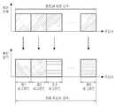
도 1a는 본 발명의 실시예에 따른 제1타입 세그먼트 사용 방식을 도시한 도면이다.1A is a diagram illustrating a method of using a first type segment according to an embodiment of the present invention.
도 1a에 도시되어 있는 바와 같이, 제1타입 세그먼트 사용 방식은 모든 세그먼트들의 크기가 동일하게 사용하는 방식을 나타낸다. 즉, 도 1a에서는 1개의 세그먼트가 1개의 부분 대역을 포함하고, N개의 세그먼트들, 즉 제1세그먼트 내지 제N세그먼트의 크기가 모두 동일하다.As shown in FIG. 1A, the method of using the first type segment indicates a method of using the same size of all the segments. That is, in FIG. 1A, one segment includes one partial band, and the sizes of the N segments, that is, the first segment to the Nth segment are all the same.
도 1a에서는 본 발명의 실시예에 따른 제1타입 세그먼트 사용 방식에 대해서 설명하였으며, 다음으로 도 1b를 사용하여 본 발명의 실시예에 따른 제2타입 세그먼트 사용 방식에 대해서 설명하기로 한다.FIG. 1A illustrates a method of using a first type segment according to an embodiment of the present invention, and FIG. 1B illustrates a method of using a second type segment according to an embodiment of the present invention.
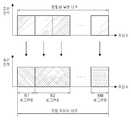
도 1b는 본 발명의 실시예에 따른 제2타입 세그먼트 사용 방식을 도시한 도면이다.1B is a diagram illustrating a method of using a second type segment according to an embodiment of the present invention.
도 1b에 도시되어 있는 바와 같이, 제2타입 세그먼트 사용 방식은 상이한 크기를 가지는 세그먼트들을 사용하는 방식을 나타낸다. 즉, 도 1b에서는 1개의 세그먼트가 1개의 부분 대역을 포함할 수도 있고, 2개의 부분 대역들을 포함할 수도 있고, M개의 세그먼트들, 즉 제1세그먼트 내지 제M세그먼트의 크기가 모두 동일하지는 않다. 일 예로, 제1세그먼트는 1개의 부분 대역을 포함하고, 제2세그먼트는 2개 의 부분 대역들을 포함하여 그 크기가 상이함을 알 수 있다.As shown in FIG. 1B, the second type segment usage scheme shows a method of using segments having different sizes. That is, in FIG. 1B, one segment may include one sub-band, and may include two sub-bands, and the sizes of the M segments, that is, the first to Mth segments are not all the same. In one example, it can be seen that the first segment includes one sub-band, and the second segment includes two sub-bands, differing in size.
한편, 상기 다중 셀 통신 시스템의 각 셀에서는 부분 대역 혹은 세그먼트 단위로 송신 전력을 제어할 수 있는데, 이를 도 1c에 나타내었다.Meanwhile, in each cell of the multi-cell communication system, the transmission power can be controlled in a partial band or a segment unit, as shown in FIG.
도 1c는 본 발명의 실시예에 따른 세그먼트 단위로 송신 전력을 제어하는 방식을 도시한 도면이다.1C is a diagram illustrating a method of controlling transmission power in a segment unit according to an embodiment of the present invention.
도 1c에는 세그먼트 단위로 송신 전력을 제어하는 동작이 도시되어 있으며, 각 세그먼트별로 송신 전력이 상이함을 알 수 있다. 물론, 상황에 따라 각 세그먼트별로 송신 전력이 동일할 수도 있다. 그리고, 도 1c에서 제1세그먼트 내지 제4세그먼트는 현재 사용중인 세그먼트를 나타내며, 미사용 세그먼트는 현재 사용중이지 않은 세그먼트를 나타낸다.FIG. 1C shows an operation of controlling the transmission power in units of segments, and it can be seen that the transmission power differs for each segment. Of course, the transmission power may be the same for each segment depending on the situation. In FIG. 1C, the first to fourth segments indicate the segment currently in use, and the unused segment indicates a segment that is not currently in use.
다음으로 도 2를 참조하여 본 발명의 실시예에 따른 주파수 자원 사용 시퀀스를 사용하여 주파수 자원을 사용하는 동작에 대해서 설명하기로 한다.Next, an operation of using a frequency resource using a frequency resource use sequence according to an embodiment of the present invention will be described with reference to FIG.
도 2는 본 발명의 실시예에 따른 주파수 자원 사용 시퀀스를 사용하여 주파수 자원을 사용하는 동작을 개략적으로 도시한 도면이다.FIG. 2 is a diagram schematically illustrating an operation of using a frequency resource using a frequency resource use sequence according to an embodiment of the present invention. Referring to FIG.
도 2를 참조하면, 상기 주파수 자원 사용 시퀀스는 세그먼트를 사용하는 순서를 나타낸 시퀀스이다. 즉, 각 셀에서는 각 셀에 미리 할당되어 있는 주파수 자원 사용 시퀀스를 사용하여 세그먼트를 사용한다. 따라서, 주파수 자원 사용 시퀀스의 길이는 각 셀에서 사용 가능한 세그먼트의 개수와 동일하게 된다.Referring to FIG. 2, the frequency resource use sequence is a sequence indicating the order of using the segments. That is, in each cell, a segment is used by using a frequency resource use sequence previously allocated to each cell. Therefore, the length of the frequency resource use sequence becomes equal to the number of segments available in each cell.
도 2에서는 주파수 자원 사용 시퀀스가 '세그먼트 시퀀스'로 도시되어 있으 며, 세그먼트 시퀀스가 a1a2a3 ... aN이고, 상기 세그먼트 시퀀스 a1a2a3 ... aN에 상응하게 세그먼트들이 할당된다. 즉, 세그먼트 시퀀스가 a1a2a3 ... aN이므로 세그먼트 1,세그먼트 2, ... , 세그먼트 N이 순차적으로 사용된다. 그리고, 각 셀에서 주파수 재사용 계수는 1이라고 가정하였기 때문에 최종적으로 세그먼트 N이 할당되면 주파수 재사용 계수가 1이 되는 것이다.2, a frequency resource use sequence is shown as a 'segment sequence', and a segment sequence is a1 a2 a3 ... aN , corresponding to the segment sequence a1 a2 a3 ... aN Segments are allocated. That is,
또한, 상기 도 2에서는 각 세그먼트에서 사용하는 송신 전력이 동일한 경우가 도시되어 있으나, 상기에서 설명한 바와 같이 각 세그먼트에서 사용하는 송신 전력이 상이할 수도 있음은 물론이다.In FIG. 2, the transmission power used in each segment is the same, but it is needless to say that the transmission power used in each segment may be different as described above.
이하의 설명에서는 주파수 자원 사용 시퀀스를 '세그먼트 시퀀스'로 칭하기로 하며, 세그먼트 시퀀스를 결정하는 동작에 대해서 설명하면 다음과 같다.In the following description, a frequency resource use sequence is referred to as a 'segment sequence', and an operation of determining a segment sequence will be described below.
(1) 먼저, 세그먼트 시퀀스는 세그먼트 사용 순서를 나타내며, 각 셀에서는 각 셀이 사용 가능한 세그먼트 개수와 동일한 길이를 가지는 고유한 세그먼트 시퀀스를 사용한다.(1) First, a segment sequence indicates a sequence of use of a segment, and each cell uses a unique segment sequence having a length equal to the number of usable segments.
(2) 인접 셀들간에 최초로 할당되는 세그먼트들은 서로 직교해야만 한다. 여기서, 각 셀에서 최초로 할당되는 세그먼트를 '기본 세그먼트(base segment)'라 칭하기로 한다.(2) Segments that are initially allocated between adjacent cells must be orthogonal to each other. Here, a segment initially allocated in each cell will be referred to as a " base segment ".
(3) 세그먼트 시퀀스는 ICI를 고려하여 결정되며, 세그먼트 시퀀스는 ICI를 최소화시키기 위해 주파수 재사용 계수와 섹터화 계수 등을 고려하여 결정된다.(3) The segment sequence is determined in consideration of the ICI, and the segment sequence is determined in consideration of the frequency reuse factor and the sectorization coefficient in order to minimize the ICI.
첫 번째로, 주파수 재사용 계수를 고려하여 세그먼트 시퀀스를 결정할 경우, 각 셀에서 사용하는 세그먼트 시퀀스의 종류와 기존 주파수 재사용 계수가 동일할 경우를 도 3을 참조하여 설명하면 다음과 같다. 여기서, 본 발명에서는 다중 셀 통신 시스템의 각 셀이 주파수 재사용 계수 1을 사용한다고 가정하였었기 때문에, 주파수 재사용 계수 1을 사용하는 다중 셀 통신 시스템에서 마치 주파수 재사용 계수 K를 사용하는 것처럼 동작시키고자 할 경우 설명의 편의상 '기존 주파수 재사용 계수'를 사용한다고 칭하기로 하는 것이다.First, when a segment sequence is determined in consideration of a frequency reuse factor, a case in which the types of segment sequences used in each cell and the existing frequency reuse factor are the same will be described with reference to FIG. Here, in the present invention, since it is assumed that each cell of the multi-cell communication system uses the frequency reuse factor of 1, in a multi-cell communication system using the frequency reuse factor of 1, The existing frequency reuse factor is used for convenience of explanation.
도 3은 본 발명의 실시예에 따라 각 셀에서 사용하는 세그먼트 시퀀스의 종류와 기존 주파수 재사용 계수가 동일할 경우의 세그먼트 시퀀스들을 도시한 도면이다.3 is a diagram illustrating segment sequences when the types of segment sequences used in each cell and the existing frequency reuse factor are the same according to an embodiment of the present invention.
도 3에는 기존 주파수 재사용 계수 4를 가정하였을 경우의 4개의 세그먼트 시퀀스들이 도시되어 있다. 도 3에는 일 예로 다중 셀 통신 시스템이 4개, 즉 셀 C0와, 셀 C1과, 셀 C2와, 셀 C3를 포함할 경우 각 셀에 할당되는 세그먼트 시퀀스들이 도시되어 있다. 셀 C0에 할당된 세그먼트 시퀀스가 세그먼트 시퀀스 C0이며, 셀 C1에 할당된 세그먼트 시퀀스가 세그먼트 시퀀스 C1이며, 셀 C2에 할당된 세그먼트 시퀀스가 세그먼트 시퀀스 C2이며, 셀 C3에 할당된 세그먼트 시퀀스가 세그먼트 시퀀스 C3이다. 여기서, 세그먼트 시퀀스 C0와, 세그먼트 시퀀스 C1과, 세그먼트 시퀀스 C2와, 세그먼트 시퀀스 C3는 하기에 나타낸 바와 같다.FIG. 3 shows four segment sequences when the conventional
세그먼트 시퀀스 C0: A-세그먼트 -> B-세그먼트 -> C-세그먼트 -> D-세그먼트Segment Sequence C0: A-Segment-> B-Segment-> C- Segment-> D- Segment
세그먼트 시퀀스 C1: B-세그먼트 ->C-세그먼트 ->D-세그먼트 ->A-세그먼트Segment Sequence C1: B-Segment-> C- Segment-> D- Segment-> A- Segment
세그먼트 시퀀스 C2: C-세그먼트 -> D-세그먼트 ->A-세그먼트 ->B-세그먼트Segment sequence C2: C-segment-> D-segment-> A-segment-> B-segment
세그먼트 시퀀스 C3: D-세그먼트 -> A-세그먼트 ->B-세그먼트 -> C-세그먼트Segment sequence C3: D-segment-> A-segment-> B-segment-> C-segment
두 번째로, 섹터화 계수를 고려하여 세그먼트 시퀀스를 결정할 경우, 각 셀에서 사용하는 세그먼트 시퀀스의 종류와 섹터화 계수가 동일할 경우를 도 4를 참조하여 설명하면 다음과 같다.Second, when a segment sequence is determined in consideration of a sectorization coefficient, a case in which the type of segment sequence used in each cell and the sectorization coefficient are the same will be described with reference to FIG.
도 4는 본 발명의 실시예에 따라 각 셀에서 사용하는 세그먼트 시퀀스의 종류와 섹터화 계수가 동일할 경우의 세그먼트 시퀀스들을 도시한 도면이다.FIG. 4 is a diagram showing segment sequences when segment segment types used in each cell are equal to sector segment coefficients according to an embodiment of the present invention.
도 4에는 기존 주파수 재사용 계수 3을 가정하였을 경우의 3개의 세그먼트 시퀀스들이 도시되어 있다. 도 3에는 일 예로 다중 셀 통신 시스템의 임의의 셀 C0가 3개, 즉 섹터 α와, 섹터 β와, 섹터 γ를 포함할 경우 각 섹터에 할당되는 세그먼트 시퀀스들이 도시되어 있다. 셀 C0의 섹터 α에 할당된 세그먼트 시퀀스가 세그먼트 시퀀스 C0-α이며, 셀 C0의 섹터 β에 할당된 세그먼트 시퀀스가 세그먼트 시퀀스 C0-β이며, 셀 C0의 섹터 γ에 할당된 세그먼트 시퀀스가 세그먼트 시퀀스 C0-γ이다. 여기서, 세그먼트 시퀀스 C0-α와, 세그먼트 시퀀스 C0-β과, 세그먼트 시퀀스 C0-γ는 하기에 나타낸 바와 같다.FIG. 4 shows three segment sequences when the conventional
세그먼트 시퀀스 C0-α: A-세그먼트 -> B-세그먼트 -> C-세그먼트Segment Sequence C0-α: A-Segment-> B-Segment-> C-Segment
세그먼트 시퀀스 C0-β: B-세그먼트 ->C-세그먼트 ->A-세그먼트Segment Sequence C0 -?: B - Segment -> C - Segment -> A - Segment
세그먼트 시퀀스 C0-γ: C-세그먼트->A-세그먼트 ->B-세그먼트Segment Sequence C0-γ: C-Segment-> A-Segment-> B-Segment
그러면 여기서 본 발명에서 제안하는 IFR 방식을 기존 주파수 재사용 계수 3과, 기존 주파수 재사용 계수 4와, 기존 주파수 재사용 계수 7을 일 예로 하여 설 명하기로 한다.Here, the IFR scheme proposed in the present invention will be described as an example of the existing
도 5는 본 발명의 실시예에 따른 기존 주파수 재사용 계수 3을 사용하고, 제1타입 세그먼트 사용 방식을 하고, 전방향 셀 구조를 사용할 경우의 IFR 방식을 도시한 도면이다.FIG. 5 is a diagram illustrating an IFR scheme using a conventional
도 5에는 기존 주파수 재사용 계수 3을 사용하고, 제1타입 세그먼트 사용 방식을 사용하고, 전방향 셀 구조를 사용할 경우의 3개의 세그먼트 시퀀스들이 도시되어 있다. 도 5에는 일 예로 다중 셀 통신 시스템이 기존 주파수 재사용 계수 3을 사용할 경우, 즉 셀 C0와, 셀 C1과, 셀 C2를 기준으로 셀을 구성할 경우 각 셀에 할당되는 세그먼트 시퀀스들이 도시되어 있다. 셀 C0에 할당된 세그먼트 시퀀스가 세그먼트 시퀀스 C0이며, 셀 C1에 할당된 세그먼트 시퀀스가 세그먼트 시퀀스 C1이며, 셀 C2에 할당된 세그먼트 시퀀스가 세그먼트 시퀀스 C2이다. 여기서, 세그먼트 시퀀스 C0와, 세그먼트 시퀀스 C1과, 세그먼트 시퀀스 C2는 하기에 나타낸 바와 같다.FIG. 5 shows three segment sequences when a conventional
세그먼트 시퀀스 C0: A-세그먼트 -> B-세그먼트 -> C-세그먼트Segment sequence C0: A-segment -> B-segment -> C-segment
세그먼트 시퀀스 C1: B-세그먼트 ->C-세그먼트->A-세그먼트Segment sequence C1: B-segment-> C-segment-> A-segment
세그먼트 시퀀스 C2: C-세그먼트 -> A-세그먼트 ->B-세그먼트Segment sequence C2: C-segment -> A-segment -> B-segment
도 6은 본 발명의 실시예에 따른 기존 주파수 재사용 계수 3을 사용하고, 제2타입 세그먼트 사용 방식을 사용하고, 전방향 셀 구조를 사용할 경우의 IFR 방식을 도시한 도면이다.FIG. 6 is a diagram illustrating an IFR scheme using an existing
도 6에는 기존 주파수 재사용 계수 3을 사용하고, 제2타입 세그먼트 사용 방 식을 사용하고, 전방향 셀 구조를 사용할 경우의 3개의 세그먼트 시퀀스들이 도시되어 있다. 도 6에는 일 예로 다중 셀 통신 시스템이 기존 주파수 재사용 계수 3을 사용할 경우, 즉 셀 C0와, 셀 C1과, 셀 C2를 기준으로 셀을 구성할 경우 각 셀에 할당되는 세그먼트 시퀀스들이 도시되어 있다. 셀 C0에 할당된 세그먼트 시퀀스가 세그먼트 시퀀스 C0이며, 셀 C1에 할당된 세그먼트 시퀀스가 세그먼트 시퀀스 C1이며, 셀 C2에 할당된 세그먼트 시퀀스가 세그먼트 시퀀스 C2이다. 여기서, 세그먼트 시퀀스 C0와, 세그먼트 시퀀스 C1과, 세그먼트 시퀀스 C2는 하기에 나타낸 바와 같다.FIG. 6 shows three segment sequences when the conventional
세그먼트 시퀀스 C0: A-세그먼트 -> 결합 세그먼트(B-세그먼트 + C-세그먼트)Segment Sequence C0: A-Segment-> Combined Segment (B-Segment + C-Segment)
세그먼트 시퀀스 C1: B-세그먼트 -> 결합 세그먼트(A-세그먼트+C-세그먼트)Segment Sequence C1: B-Segment-> Combined Segment (A-Segment + C-Segment)
세그먼트 시퀀스 C2: C-세그먼트 -> 결합 세그먼트(A-세그먼트 +B-세그먼트)Segment Sequence C2: C-Segment-> Combined Segment (A-Segment + B-Segment)
여기서, 결합 세그먼트라함은 각 셀에서 사용하는 세그먼트들중 기본 세그먼트를 제외한 세그먼트들중 일부 혹은 전부가 결합된 세그먼트를 나타낸다. 도 6에서는 결합 세그먼트가 각 셀에서 사용하는 세그먼트들중 기본 세그먼트를 제외한 세그먼트들중 전부가 결합된 세그먼트를 나타낸다.Here, the combined segment indicates a segment in which some or all of the segments other than the basic segment among the segments used in each cell are combined. In FIG. 6, all of the segments other than the basic segment among the segments used by the combining segment in each cell represent segments.
도 7은 본 발명의 실시예에 따른 기존 주파수 재사용 계수 3을 사용하고, 제1타입 세그먼트 사용 방식을 하고, 섹터 셀 구조를 사용할 경우의 IFR 방식을 도시한 도면이다.FIG. 7 is a diagram illustrating an IFR scheme when a conventional
도 7에는 기존 주파수 재사용 계수 3을 사용하고, 제1타입 세그먼트 사용 방 식을 사용하고, 섹터 셀 구조를 사용할 경우의 3개의 세그먼트 시퀀스들이 도시되어 있다.FIG. 7 shows three segment sequences when the conventional
도 7에는 일 예로 다중 셀 통신 시스템이 포함하는 셀들 각각이 3개, 즉 섹터 α와, 섹터 β와, 섹터 γ를 포함할 경우 임의의 셀인 셀 C0의 각 섹터에 할당되는 세그먼트 시퀀스들이 도시되어 있다. 셀 C0의 섹터 α에 할당된 세그먼트 시퀀스가 세그먼트 시퀀스 C0-α이며, 셀 C0의 섹터 β에 할당된 세그먼트 시퀀스가 세그먼트 시퀀스 C0-β이며, 셀 C0의 섹터 γ에 할당된 세그먼트 시퀀스가 세그먼트 시퀀스 C0-γ이다. 여기서, 세그먼트 시퀀스 C0-α와, 세그먼트 시퀀스 C0-β과, 세그먼트 시퀀스 C0-γ는 하기에 나타낸 바와 같다.7 shows segment sequences allocated to each sector of the cell C0, which is an arbitrary cell, when each of the cells included in the multi-cell communication system includes three sectors: alpha, sector beta and sector y . The segment sequence assigned to the sector? Of the cell C0 is the segment sequence C0- ?, the segment sequence assigned to the sector? Of the cell C0 is the segment sequence C0- ?, the segment sequence assigned to the sector? Of the cell C0 is the segment sequence C0 -γ. Here, the segment sequence C0-?, The segment sequence C0-?, And the segment sequence C0-? Are as follows.
세그먼트 시퀀스 C0-α: A-세그먼트 -> B-세그먼트 -> C-세그먼트Segment Sequence C0-α: A-Segment-> B-Segment-> C-Segment
세그먼트 시퀀스 C0-β: B-세그먼트 ->C-세그먼트 ->A-세그먼트Segment Sequence C0 -?: B - Segment -> C - Segment -> A - Segment
세그먼트 시퀀스 C0-γ: C-세그먼트->A-세그먼트 ->B-세그먼트Segment Sequence C0-γ: C-Segment-> A-Segment-> B-Segment
도 8은 본 발명의 실시예에 따른 기존 주파수 재사용 계수 4를 사용하고, 제1타입 세그먼트 사용 방식을 하고, 전방향 셀 구조를 사용할 경우의 IFR 방식을 도시한 도면이다.FIG. 8 is a diagram illustrating an IFR scheme in which a conventional
도 8에는 기존 주파수 재사용 계수 4를 사용하고, 제1타입 세그먼트 사용 방식을 사용하고, 전방향 셀 구조를 사용할 경우의 4개의 세그먼트 시퀀스들이 도시되어 있다. 도 8에는 일 예로 다중 셀 통신 시스템이 기존 주파수 재사용 계수 4를 사용할 경우, 즉 셀 C0와, 셀 C1과, 셀 C2와, 셀 C3를 기준으로 셀을 구성할 경우 각 셀에 할당되는 세그먼트 시퀀스들이 도시되어 있다. 셀 C0에 할당된 세그먼트 시퀀스가 세그먼트 시퀀스 C0이며, 셀 C1에 할당된 세그먼트 시퀀스가 세그먼트 시퀀스 C1이며, 셀 C2에 할당된 세그먼트 시퀀스가 세그먼트 시퀀스 C2이며, 셀 C3에 할당된 세그먼트 시퀀스가 세그먼트 시퀀스 C3이다. 여기서, 세그먼트 시퀀스 C0와, 세그먼트 시퀀스 C1과, 세그먼트 시퀀스 C2, 세그먼트 시퀀스 C3는 하기에 나타낸 바와 같다.FIG. 8 shows four segment sequences when the conventional
세그먼트 시퀀스 C0: A-세그먼트 -> B-세그먼트 -> C-세그먼트 -> D-세그먼트Segment Sequence C0: A-Segment-> B-Segment-> C- Segment-> D- Segment
세그먼트 시퀀스 C1: B-세그먼트 ->C-세그먼트 ->D-세그먼트 ->A-세그먼트Segment Sequence C1: B-Segment-> C- Segment-> D- Segment-> A- Segment
세그먼트 시퀀스 C2: C-세그먼트 -> D-세그먼트 ->A-세그먼트 ->B-세그먼트Segment sequence C2: C-segment-> D-segment-> A-segment-> B-segment
세그먼트 시퀀스 C3: D-세그먼트 -> A-세그먼트 ->B-세그먼트 -> C-세그먼트Segment sequence C3: D-segment-> A-segment-> B-segment-> C-segment
도 9는 본 발명의 실시예에 따른 기존 주파수 재사용 계수 4를 사용하고, 제2타입 세그먼트 사용 방식을 사용하고, 전방향 셀 구조를 사용할 경우의 IFR 방식의 제1예를 도시한 도면이다.9 is a diagram illustrating a first example of an IFR scheme using an existing
도 9에는 기존 주파수 재사용 계수 4를 사용하고, 제2타입 세그먼트 사용 방식을 사용하고, 전방향 셀 구조를 사용할 경우의 4개의 세그먼트 시퀀스들이 도시되어 있다. 도 9에는 일 예로 다중 셀 통신 시스템이 기존 주파수 재사용 계수 4를 사용할 경우, 즉 셀 C0와, 셀 C1과, 셀 C2와, 셀 C3를 기준으로 셀을 구성할 경우 각 셀에 할당되는 세그먼트 시퀀스들이 도시되어 있다. 셀 C0에 할당된 세그먼트 시퀀스가 세그먼트 시퀀스 C0이며, 셀 C1에 할당된 세그먼트 시퀀스가 세그먼트 시퀀스 C1이며, 셀 C2에 할당된 세그먼트 시퀀스가 세그먼트 시퀀스 C2이며, 셀 C3에 할당된 세그먼트 시퀀스가 C3이다. 여기서, 세그먼트 시퀀스 C0와, 세그먼트 시퀀스 C1과, 세그먼트 시퀀스 C2와, 세그먼트 시퀀스 C3는 하기에 나타낸 바와 같다.FIG. 9 shows four segment sequences when the existing
세그먼트 시퀀스 C0: A-세그먼트 -> 결합 세그먼트(B-세그먼트 + C-세그먼트) -> D-세그먼트Segment Sequence C0: A-Segment-> Combined Segment (B-Segment + C-Segment) -> D-Segment
세그먼트 시퀀스 C1: B-세그먼트 -> 결합 세그먼트(C-세그먼트+D-세그먼트) -> A-세그먼트Segment Sequence C1: B-Segment-> Combined Segment (C-Segment + D-Segment) -> A-Segment
세그먼트 시퀀스 C2: C-세그먼트 -> 결합 세그먼트(A-세그먼트 +D-세그먼트)->B-세그먼트Segment Sequence C2: C-Segment -> Combined Segment (A-Segment + D-Segment) -> B-Segment
세그먼트 시퀀스 C3: D-세그먼트 -> 결합 세그먼트(A-세그먼트 +B-세그먼트)->C-세그먼트Segment Sequence C3: D-Segment-> Combined Segment (A-Segment + B-Segment) -> C-Segment
상기 도 9에서는 결합 세그먼트가 각 셀에서 사용하는 세그먼트들중 기본 세그먼트를 제외한 세그먼트들중 일부가 결합된 경우를 나타낸다.FIG. 9 shows a case where some of the segments other than the basic segment among the segments used in each cell of the combined segment are combined.
도 10은 본 발명의 실시예에 따른 기존 주파수 재사용 계수 4를 사용하고, 제2타입 세그먼트 사용 방식을 사용하고, 전방향 셀 구조를 사용할 경우의 IFR 방식의 제2예를 도시한 도면이다.10 is a diagram illustrating a second example of an IFR scheme in which a conventional
도 10에는 기존 주파수 재사용 계수 4를 사용하고, 제2타입 세그먼트 사용 방식을 사용하고, 전방향 셀 구조를 사용할 경우의 4개의 세그먼트 시퀀스들이 도시되어 있다. 도 10에는 일 예로 다중 셀 통신 시스템이 기존 주파수 재사용 계수 4를 사용할 경우, 즉 셀 C0와, 셀 C1과, 셀 C2와, 셀 C3를 기준으로 셀을 구성할 경우 각 셀에 할당되는 세그먼트 시퀀스들이 도시되어 있다. 셀 C0에 할당된 세그 먼트 시퀀스가 세그먼트 시퀀스 C0이며, 셀 C1에 할당된 세그먼트 시퀀스가 세그먼트 시퀀스 C1이며, 셀 C2에 할당된 세그먼트 시퀀스가 세그먼트 시퀀스 C2이며, 셀 C3에 할당된 세그먼트 시퀀스가 C3이다. 여기서, 세그먼트 시퀀스 C0와, 세그먼트 시퀀스 C1과, 세그먼트 시퀀스 C2와, 세그먼트 시퀀스 C3는 하기에 나타낸 바와 같다.FIG. 10 shows four segment sequences when the existing
세그먼트 시퀀스 C0: A-세그먼트 -> B-세그먼트 -> 결합 세그먼트(C-세그먼트 + D-세그먼트)Segment Sequence C0: A-Segment-> B-Segment-> Combined Segment (C-Segment + D-Segment)
세그먼트 시퀀스 C1: B-세그먼트 -> C-세그먼트 -> 결합 세그먼트(A-세그먼트+D-세그먼트)Segment Sequence C1: B-Segment-> C-Segment-> Combined Segment (A-Segment + D-Segment)
세그먼트 시퀀스 C2: C-세그먼트->D-세그먼트 -> 결합 세그먼트(A-세그먼트 +B-세그먼트)Segment Sequence C2: C-Segment-> D-Segment-> Combined Segment (A-Segment + B-Segment)
세그먼트 시퀀스 C3: D-세그먼트 ->A-세그먼트-> 결합 세그먼트(B-세그먼트 +C-세그먼트)Segment sequence C3: D-segment-> A-segment-> Combined segment (B-segment + C-segment)
도 11은 본 발명의 실시예에 따른 기존 주파수 재사용 계수 4를 사용하고, 제2타입 세그먼트 사용 방식을 사용하고, 전방향 셀 구조를 사용할 경우의 IFR 방식의 제3예를 도시한 도면이다.11 is a diagram illustrating a third example of an IFR scheme using an existing
도 11에는 기존 주파수 재사용 계수 4를 사용하고, 제2타입 세그먼트 사용 방식을 사용하고, 전방향 셀 구조를 사용할 경우의 4개의 세그먼트 시퀀스들이 도시되어 있다. 도 11에는 일 예로 다중 셀 통신 시스템이 기존 주파수 재사용 계수 4를 사용할 경우, 즉 셀 C0와, 셀 C1과, 셀 C2와, 셀 C3를 기준으로 셀을 구성할 경우 각 셀에 할당되는 세그먼트 시퀀스들이 도시되어 있다. 셀 C0에 할당된 세그먼트 시퀀스가 세그먼트 시퀀스 C0이며, 셀 C1에 할당된 세그먼트 시퀀스가 세그먼트 시퀀스 C1이며, 셀 C2에 할당된 세그먼트 시퀀스가 세그먼트 시퀀스 C2이며, 셀 C3에 할당된 세그먼트 시퀀스가 C3이다. 여기서, 세그먼트 시퀀스 C0와, 세그먼트 시퀀스 C1과, 세그먼트 시퀀스 C2와, 세그먼트 시퀀스 C3는 하기에 나타낸 바와 같다.FIG. 11 shows four segment sequences when the conventional
세그먼트 시퀀스 C0: A-세그먼트 ->결합 세그먼트(B-세그먼트+C-세그먼트 + D-세그먼트)Segment Sequence C0: A-Segment-> Combined Segment (B-Segment + C-Segment + D-Segment)
세그먼트 시퀀스 C1: B-세그먼트 -> 결합 세그먼트(A-세그먼트+C-세그먼트+D-세그먼트)Segment Sequence C1: B-Segment-> Combined Segment (A-Segment + C-Segment + D-Segment)
세그먼트 시퀀스 C2: C-세그먼트->결합 세그먼트(A-세그먼트 +B-세그먼트+D-세그먼트)Segment Sequence C2: C-Segment-> Combined Segment (A-Segment + B-Segment + D-Segment)
세그먼트 시퀀스 C3: D-세그먼트 ->결합 세그먼트(A-세그먼트+B-세그먼트 +C-세그먼트)Segment Sequence C3: D-Segment-> Combined Segment (A-Segment + B-Segment + C-Segment)
도 12는 본 발명의 실시예에 따른 기존 주파수 재사용 계수 4를 사용하고, 제1타입 세그먼트 사용 방식을 하고, 섹터 셀 구조를 사용할 경우의 IFR 방식을 도시한 도면이다.12 is a diagram illustrating an IFR scheme using a conventional
도 12에는 기존 주파수 재사용 계수 3을 사용하고, 제1타입 세그먼트 사용 방식을 사용하고, 섹터 셀 구조를 사용할 경우의 12개의 세그먼트 시퀀스들이 도시되어 있다.12 shows a sequence of 12 segments when the conventional
도 12에는 일 예로 다중 셀 통신 시스템이 포함하는 셀들 각각이 3개, 즉 섹터 α와, 섹터 β와, 섹터 γ를 포함할 경우 임의의 셀들인 셀 C0 내지 C3의 각 섹터에 할당되는 세그먼트 시퀀스들이 도시되어 있다. 셀 C0의 섹터 α에 할당된 세그먼트 시퀀스가 세그먼트 시퀀스 C0-S00이며, 셀 C0의 섹터 β에 할당된 세그먼트 시퀀스가 세그먼트 시퀀스 C0-S01이며, 셀 C0의 섹터 γ에 할당된 세그먼트 시퀀스가 세그먼트 시퀀스 C0-S02이고, 셀 C1의 섹터 α에 할당된 세그먼트 시퀀스가 세그먼트 시퀀스 C1-S03이며, 셀 C1의 섹터 β에 할당된 세그먼트 시퀀스가 세그먼트 시퀀스 C1-S04이며, 셀 C1의 섹터 γ에 할당된 세그먼트 시퀀스가 세그먼트 시퀀스 C1-S05이며, 셀 C2의 섹터 α에 할당된 세그먼트 시퀀스가 세그먼트 시퀀스 C2-S06이며, 셀 C2의 섹터 β에 할당된 세그먼트 시퀀스가 세그먼트 시퀀스 C2-S07이며, 셀 C2의 섹터 γ에 할당된 세그먼트 시퀀스가 세그먼트 시퀀스 C2-S08이며, 셀 C3의 섹터 α에 할당된 세그먼트 시퀀스가 세그먼트 시퀀스 C3-S09이며, 셀 C3의 섹터 β에 할당된 세그먼트 시퀀스가 세그먼트 시퀀스 C3-S10이며, 셀 C3의 섹터 γ에 할당된 세그먼트 시퀀스가 세그먼트 시퀀스 C3-S11이다. 여기서, 세그먼트 시퀀스 C0-S00와, 세그먼트 시퀀스 C0-S01과, 세그먼트 시퀀스 C0-S02와, 세그먼트 시퀀스 C1-S03와, 세그먼트 시퀀스 C1-S04와, 세그먼트 시퀀스 C1-S05와, 세그먼트 시퀀스 C2-S06와, 세그먼트 시퀀스 C2-S07과, 세그먼트 시퀀스 C2-S08과, 세그먼트 시퀀스 C3-S09와, 세그먼트 시퀀스 C3-S10과, 세그먼트 시퀀스 C3-S11는 하기에 나타낸 바와 같다.In FIG. 12, for example, when each cell included in the multi-cell communication system includes three sectors: a, sector beta and sector y, segment sequences allocated to each sector of cells C0 to C3 Respectively. The segment sequence assigned to the sector? Of the cell C0 is the segment sequence C0-S00, the segment sequence assigned to the sector? Of the cell C0 is the segment sequence C0-S01, the segment sequence allocated to the sector? Of the cell C0 is the segment sequence C0 -S02, the segment sequence assigned to the sector? Of the cell C1 is the segment sequence C1-S03, the segment sequence assigned to the sector beta of the cell C1 is the segment sequence C1-S04, and the segment sequence assigned to the sector? Is the segment sequence C1-S05, the segment sequence assigned to the sector alpha of the cell C2 is the segment sequence C2-S06, the segment sequence assigned to the sector beta of the cell C2 is the segment sequence C2-S07, The segment sequence assigned to the sector? Of the cell C3 is the segment sequence C3-S09, the segment sequence assigned to the sector? Of the cell C3 is the segment sequence C2-S08, The bit sequence is a sequence segment C3-S10, is the segment sequence assigned to sector γ of the cell C3 sequence segments C3-S11. Here, the segment sequence C0 to S00, the segment sequence C0 to S01, the segment sequence C0 to S02, the segment sequence C1 to S03, the segment sequence C1 to S04, the segment sequence C1 to S05, the segment sequence C2 to S06 , The segment sequence C2-S07, the segment sequence C2-S08, the segment sequence C3-S09, the segment sequence C3-S10, and the segment sequence C3-S11 are as follows.
세그먼트 시퀀스 C0-S00: A-세그먼트->B-세그먼트->C-세그먼트->D-세그먼트 ->E-세그먼트->F-세그먼트->G-세그먼트->H-세그먼트->I-세그먼트->J-세그먼트->K-세그먼트->L-세그먼트Segment Sequence C0-S00: A-Segment-> B-Segment-> C- Segment-> D- Segment-> E- Segment-> F- Segment-> G- Segment-> H- Segment-> I- Segment-> > J-segment -> K-segment -> L-segment
세그먼트 시퀀스 C0-S01:B-세그먼트->C-세그먼트->D-세그먼트->E-세그먼트->F-세그먼트->G-세그먼트->H-세그먼트->I-세그먼트->J-세그먼트->K-세그먼트->L-세그먼트->A-세그먼트Segment Sequence C0-S01: B-Segment-> C- Segment-> D- Segment-> E-Segment-> F- Segment-> G- Segment-> H- Segment-> I- Segment-> J- Segment-> > K-segment -> L-segment -> A-segment
세그먼트 시퀀스 C0-S02:C-세그먼트->D-세그먼트->E-세그먼트->F-세그먼트->G-세그먼트->H-세그먼트->I-세그먼트->J-세그먼트->K-세그먼트->L-세그먼트->A-세그먼트->B-세그먼트Segment Sequence C0-S02: C-Segment-> D- Segment-> E-Segment-> F- Segment-> G- Segment-> H- Segment-> I- Segment-> J- Segment-> K- Segment-> > L-segment -> A-segment -> B-segment
세그먼트 시퀀스 C1-S03:D-세그먼트->E-세그먼트->F-세그먼트->G-세그먼트->H-세그먼트->I-세그먼트->J-세그먼트->K-세그먼트->L-세그먼트->A-세그먼트->B-세그먼트->C-세그먼트Segment Sequence C1-S03: D-Segment-> E-Segment-> F- Segment-> G- Segment-> H- Segment-> I- Segment-> J- Segment-> K- Segment-> L- Segment-> > A-segment -> B-segment -> C-segment
세그먼트 시퀀스 C1-S04:E-세그먼트->F-세그먼트->G-세그먼트->H-세그먼트->I-세그먼트->J-세그먼트->K-세그먼트->L-세그먼트->A-세그먼트->B-세그먼트->C-세그먼트->D-세그먼트 Segment Sequence C1-S04: E-Segment-> F- Segment-> G- Segment-> H- Segment-> I- Segment-> J- Segment-> K- Segment-> L- Segment-> A- Segment-> > B-segment -> C-segment -> D-segment
세그먼트 시퀀스 C1-S05:F-세그먼트->G-세그먼트->H-세그먼트->I-세그먼트->J-세그먼트->K-세그먼트->L-세그먼트->A-세그먼트->B-세그먼트->C-세그먼트->D-세그먼트->E-세그먼트 Segment Sequence C1-S05: F-Segment-> G- Segment-> H- Segment-> I- Segment-> J- Segment-> K- Segment-> L- Segment-> A- Segment-> B- Segment-> > C-segment -> D-segment -> E-segment
세그먼트 시퀀스 C2-S06:G-세그먼트->H-세그먼트->I-세그먼트->J-세그먼트->K-세그먼트->L-세그먼트->A-세그먼트->B-세그먼트->C-세그먼트->D-세그먼트->E-세그먼트->F-세그먼트Segment Sequence C2-S06: G-Segment-> H- Segment-> I- Segment-> J- Segment-> K- Segment-> L- Segment-> A- Segment-> B- Segment-> C- Segment-> > D-Segment -> E-Segment -> F-Segment
세그먼트 시퀀스 C2-S07:H-세그먼트->I-세그먼트->J-세그먼트->K-세그먼트->L-세그먼트->A-세그먼트->B-세그먼트->C-세그먼트->D-세그먼트->E-세그먼트->F-세그먼트->G-세그먼트Segment Sequence C2-S07: H-Segment-> I- Segment-> J- Segment-> K- Segment-> L- Segment-> A- Segment-> B- Segment-> C- Segment-> D- Segment-> > E-segment -> F-segment -> G-segment
세그먼트 시퀀스 C2-S08:I-세그먼트->J-세그먼트->K-세그먼트->L-세그먼트->A-세그먼트->B-세그먼트->C-세그먼트->D-세그먼트->E-세그먼트->F-세그먼트->G-세그먼트->H-세그먼트Segment Sequence C2-S08: I- Segment-> J- Segment-> K- Segment-> L- Segment-> A- Segment-> B- Segment-> C- Segment-> D- Segment-> E- Segment-> > F-Segment -> G-Segment -> H-Segment
세그먼트 시퀀스 C3-S09:J-세그먼트->K-세그먼트->L-세그먼트->A-세그먼트->B-세그먼트->C-세그먼트->D-세그먼트->E-세그먼트->F-세그먼트->G-세그먼트->H-세그먼트->I-세그먼트Segment Sequence C3-S09: J-Segment-> K- Segment-> L- Segment-> A- Segment-> B- Segment-> C- Segment-> D- Segment-> E- Segment-> F- Segment-> > G-Segment -> H-Segment -> I-Segment
세그먼트 시퀀스 C3-S10:K-세그먼트->L-세그먼트->A-세그먼트->B-세그먼트->C-세그먼트->D-세그먼트->E-세그먼트->F-세그먼트->G-세그먼트->H-세그먼트->I-세그먼트->J-세그먼트Segment Sequence C3-S10: K-Segment-> L- Segment-> A- Segment-> B- Segment-> C- Segment-> D- Segment-> E- Segment-> F- Segment-> G- Segment-> > H-Segment -> I-Segment -> J-Segment
세그먼트 시퀀스 C3-S11:L-세그먼트->A-세그먼트->B-세그먼트->C-세그먼트->D-세그먼트->E-세그먼트->F-세그먼트->G-세그먼트->H-세그먼트->I-세그먼트->J-세그먼트->K-세그먼트Segment Sequence C3-S11: L-Segment-> A- Segment-> B- Segment-> C- Segment-> D- Segment-> E- Segment-> F- Segment-> G- Segment-> H- Segment-> > I-Segment -> J-Segment -> K-Segment
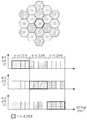
도 13은 본 발명의 실시예에 따른 기존 주파수 재사용 계수 7을 사용하고, 제1타입 세그먼트 사용 방식을 하고, 전방향 셀 구조를 사용할 경우의 IFR 방식을 도시한 도면이다.FIG. 13 is a diagram illustrating an IFR scheme in which a conventional
도 13에는 기존 주파수 재사용 계수 7을 사용하고, 제1타입 세그먼트 사용 방식을 사용하고, 전방향 셀 구조를 사용할 경우의 7개의 세그먼트 시퀀스들이 도 시되어 있다. 도 13에는 일 예로 다중 셀 통신 시스템이 기존 주파수 재사용 계수 7을 사용할 경우, 즉 셀 C0와, 셀 C1과, 셀 C2와, 셀 C3과, 셀 3과, 셀 4와, 셀 5와, 셀 6을 기준으로 셀을 구성할 경우 각 셀에 할당되는 세그먼트 시퀀스들이 도시되어 있다. 셀 C0에 할당된 세그먼트 시퀀스가 세그먼트 시퀀스 C0이며, 셀 C1에 할당된 세그먼트 시퀀스가 세그먼트 시퀀스 C1이며, 셀 C2에 할당된 세그먼트 시퀀스가 세그먼트 시퀀스 C2이며, 셀 C3에 할당된 세그먼트 시퀀스가 세그먼트 시퀀스 C3이고, 셀 C4에 할당된 세그먼트 시퀀스가 세그먼트 시퀀스 C4이며, 셀 C5에 할당된 세그먼트 시퀀스가 세그먼트 시퀀스 C5이며, 셀 C6에 할당된 세그먼트 시퀀스가 세그먼트 시퀀스 C6이다. 여기서, 세그먼트 시퀀스 C0와, 세그먼트 시퀀스 C1과, 세그먼트 시퀀스 C2, 세그먼트 시퀀스 C3와, 세그먼트 시퀀스 C4와, 세그먼트 시퀀스 C5와, 세그먼트 시퀀스 C6은 하기에 나타낸 바와 같다.FIG. 13 shows seven segment sequences when the conventional
세그먼트 시퀀스 C0: A-세그먼트 -> B-세그먼트 -> C-세그먼트 -> D-세그먼트->E-세그먼트->F-세그먼트->G-세그먼트Segment Sequence C0: A- Segment-> B- Segment-> C- Segment-> D- Segment-> E- Segment-> F- Segment-> G- Segment
세그먼트 시퀀스 C1: B-세그먼트 -> C-세그먼트 -> D-세그먼트->E-세그먼트->F-세그먼트->G-세그먼트-> A-세그먼트Segment Sequence C1: B-Segment-> C- Segment-> D- Segment-> E-Segment-> F- Segment-> G- Segment-> A- Segment
세그먼트 시퀀스 C2: C-세그먼트 -> D-세그먼트->E-세그먼트->F-세그먼트->G-세그먼트-> A-세그먼트 ->B-세그먼트Segment Sequence C2: C-Segment-> D- Segment-> E-Segment-> F- Segment-> G- Segment-> A- Segment-> B- Segment
세그먼트 시퀀스 C3: D-세그먼트->E-세그먼트->F-세그먼트->G-세그먼트-> A-세그먼트 ->B-세그먼트->C-세그먼트Segment Sequence C3: D-Segment-> E-Segment-> F- Segment-> G- Segment-> A- Segment-> B- Segment-> C- Segment
세그먼트 시퀀스 C4: E-세그먼트->F-세그먼트->G-세그먼트-> A-세그먼트 ->B-세그먼트->C-세그먼트->D-세그먼트Segment Sequence C4: E-Segment-> F- Segment-> G- Segment-> A- Segment-> B- Segment-> C- Segment-> D- Segment
세그먼트 시퀀스 C5: F-세그먼트->G-세그먼트-> A-세그먼트 ->B-세그먼트->C-세그먼트->D-세그먼트->E-세그먼트Segment Sequence C5: F-Segment-> G- Segment-> A- Segment-> B- Segment-> C- Segment-> D- Segment-> E-Segment
세그먼트 시퀀스 C6: G-세그먼트-> A-세그먼트 ->B-세그먼트->C-세그먼트->D-세그먼트->E-세그먼트->F-세그먼트Segment Sequence C6: G-Segment-> A- Segment-> B- Segment-> C- Segment-> D- Segment-> E- Segment-> F- Segment
이상 설명한 실시예들은 전체 주파수 대역을 일정 수의 부분 대역들로 분할한 후, 각 셀마다 부분 대역들의 자원 이용 순서를 체계적으로 제어함으로써 셀간 간섭을 감소시킨다.In the embodiments described above, the entire frequency band is divided into a predetermined number of partial bands, and the order of resource utilization of the partial bands is systematically controlled for each cell, thereby reducing inter-cell interference.
더욱이, 이하 실시 예들에서는 순차적인 자원 이용을 통한 체계적인 셀간 간섭 제어를 통하여, 기존의 주파수 재사용 방식들에 비해 평균적인 성능 개선 뿐만 아니라, 신호 특성이 좋지 않은 셀-경계 사용자들에게 요구되는 SINR을 보장하는 방안을 제안한다.Further, in the following embodiments, systematic intercell interference control through sequential use of resources ensures average performance improvement over existing frequency reuse schemes, as well as SINR required for cell-edge users with poor signal characteristics .
먼저, 사용자들의 분포 특성, 자원 할당에 따른 간섭 관계, 중심 셀의 주파수 부하율 등 자원 이용에 따른 요소들을 반영하여, 부분 대역 이용 순서 뿐만 아니라 부분 대역 이용 방법도 제공한다. 이하 설명에서, 부하율은 주파수 부하율을 의미한다. 또한 이하 설명에서, 부하율은 전체 할당된 주파수 대역 중 현재 사용자에게 할당한 주파수 대역의 비율을 말한다.First, it provides not only partial band usage order but also partial band utilization method reflecting the factors related to resource utilization such as distribution characteristics of users, interference relation according to resource allocation, frequency load ratio of center cell. In the following description, the load factor means the frequency load factor. In the following description, the load factor refers to the ratio of the frequency bands allocated to the current user among the entire allocated frequency bands.
먼저, 본 발명의 실시예들은 전체 주파수를 일정 수의 부분 대역들로 분할하고, 분할된 대역 중 일부 부분 대역을 기준 부하율 이하에서는 인접하는 셀들에서 간섭이 야기되지 않도록 하는 준-직교 기본 (Quasi-orthogonal fundamental) 대역으로서 정의하는데, 이를 도 14를 참조하여 설명하여 상세히 설명한다.Embodiments of the present invention provide a quasi-orthogonal basis quasi-orthogonal quasi-orthogonal quasi-orthogonal quasi-orthogonal quasi-orthogonal quasi-orthogonal quasi-orthogonal quasi-orthogonal quasi- orthogonal fundamental band, which will be described in detail with reference to FIG.
도 14는 본 발명에 따른 준 직교 기본 대역을 설명하기 위한 도면이다.FIG. 14 is a diagram for explaining a quasi-orthogonal basis band according to the present invention. FIG.
다중 셀 환경에서 셀들 상호간 간섭을 체계적으로 제어하기 위하여 각 셀에서는 미리 정의된 시퀀스에 따라 부분 대역을 순서대로 이용하며, 할당된 부분 대역 내의 자원이 모두 소진되기 전까지 해당 대역 안에서 자원 할당이 이루어진다. 이 때, 준-직교 기본 대역은 각 셀에서 가장 먼저 자원이 할당되는 대역이며, 일정한 부하율 이하에서는 준-직교 기본 대역들에서 인접한 셀들간의 간섭이 야기되지 않으므로 인접한 셀간의 간섭이 항상 낮게 유지된다.In order to systematically control inter-cell interference in a multi-cell environment, sub-bands are sequentially used according to a predefined sequence in each cell, and resources are allocated in the corresponding band until resources in the allocated sub-band are exhausted. In this case, the quasi-orthogonal base band is a band in which resources are allocated first in each cell, and below a certain load ratio, interference between adjacent cells in the quasi-orthogonal base bands is not caused, so interference between adjacent cells is always kept low .
도 14를 참조하면, 전체 가용 주파수 대역은 6개의 부분 대역들(10 내지 60)으로 분할되어 있다. 각 셀C1, C2 및 C3에 대한 부분 대역들의 자원 이용 순서, 즉, 세그먼트 시퀀스가 결정되어 있다. 예컨대, 셀 C1에서는 제2 부분 대역(20)이 가장 먼저 할당된다. 다음으로, 셀 C2 및 셀 C3에서는 제4 부분 대역(40) 및 제6 부분 대역(60)이 각각 가장 먼저 할당된다. 따라서, 제2, 제4 및 제6 부분 대역(20,40 및 60)은 각각 셀들 C1, C2 및 C3의 준-직교 기본 (Quasi-orthogonal fundamental) 대역이 된다.Referring to FIG. 14, the entire usable frequency band is divided into six sub-bands 10 to 60. The resource use order of the partial bands for each of the cells C1, C2, and C3, i.e., the segment sequence, is determined. For example, in the cell C1, the second
이러한 준 직교 기본 대역을 할당할 때, 사용자의 SINR, 사용자로부터의 높은 신호 품질 요구 등을 고려한 동적 채널 할당 (DCA: dynamic channel allocation)이 수행될 수 있다. 일 예로, 셀간 간섭이 상대적으로 낮은 준-직교 기본 대역을 SINR이 낮은 셀-경계 지역에 위치한 사용자들에 우선 할당함으로써, 셀간 간섭을 크게 감소시킬 수 있다.When allocating the quasi-orthogonal base band, dynamic channel allocation (DCA) considering the SINR of the user and a high signal quality request from the user can be performed. For example, inter-cell interference can be greatly reduced by first allocating a quasi-orthogonal base band with a relatively low inter-cell interference to users located in a low-SINR cell-boundary region.
이하, 본 발명의 실시예를 상세히 설명한다.Hereinafter, embodiments of the present invention will be described in detail.
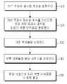
도 15는 본 발명의 실시예에 따른 주파수 자원 사용 방법을 나타낸 흐름도이다. 이러한 주파수 자원 사용 방법은 셀들의 무선 자원 할당을 제어하는 기지국에서 수행되는 것이 바람직하다.15 is a flowchart illustrating a method of using a frequency resource according to an embodiment of the present invention. The method of using frequency resources is preferably performed in a base station controlling radio resource allocation of cells.
도 15를 참조하면, 110단계에서 기지국은 기본 주파수 재사용 계수를 설정하고 120단계로 진행한다. 이때, 설정된 기본 주파수 재사용 계수는 대역 분할의 기준으로 사용 된다. 120단계에서 상기 기지국은 기본 주파수 재사용 계수를 기반으로 전체 가용 주파수 대역을 일련의 부분 대역들로 분할하고 130단계로 진행한다.Referring to FIG. 15, in step 110, the base station sets a basic frequency reuse factor and proceeds to step 120. FIG. At this time, the set basic frequency reuse factor is used as a reference of band division. In
예컨대, 전체 가용 주파수 대역은 기본 주파수 재사용 계수의 정수배로 분할되는 것이 바람직하다. 일 예로, 전체 가용 주파수 대역이 기본 주파수 재사용 계수의 2배인 경우를 설명하기로 한다. 즉, 기본 주파수 재사용 계수가 3이면, 전체 가용 주파수 대역은 6개의 부분 대역으로 분할되고, 기본 주파수 재사용 계수가 4이면, 전체 가용 주파수 대역은 8개의 부분 대역으로 분할될 수 있다.
한편, 분할 대역의 수가 증가할수록 중심-셀에서 멀리 떨어진 간섭 셀 계층으로부터의 체계적인 간섭 제어가 가능하다. 따라서, 기본 주파수 재사용 계수가 클수록 중심 셀로부터 영향을 받는 간섭 셀간의 거리가 멀어진다. 즉, 기본 주파수 재사용 계수는 최초 부분 대역 할당 시에 중심-셀이 간섭을 유발하는 셀의 범위를 결정한다. 이하, 상기 중심-셀로부터 떨어진 셀의 수를 Tier-#이라 정의하기로 한다. 일 예로, Tier-1은 상기 중심-셀을 둘러싸고 있는 첫번째 셀들을 의미하고, Tier-2는 상기 첫번째 셀들 둘러싸고 있는 다음 셀들을 의미한다.
예를 들어, 주파수 재사용 계수 3 기반의 설계에서는 먼저 Tier-2 셀들에게만 간섭이 발생하도록 중심 셀의 자원을 이용할 수 있고, 부하율이 증가함에 따라 간섭이 발생하는 셀들이 Tier-1 셀들로 확대되도록 하였다. 그러나 주파수 재사용 계수 7 기반의 설계에서는 먼저 Tier-3 셀들에게만 간섭이 발생하며, 부하율이 증가함에 따라 차례로 Tier-2, Tier-1의 셀들에게 간섭이 발생한다.For example, the entire available frequency band is preferably divided by an integer multiple of the basic frequency reuse factor. As an example, a case where the total available frequency band is twice the basic frequency reuse factor will be described. That is, if the basic frequency reuse factor is 3, the entire usable frequency band is divided into six partial bands, and if the basic frequency reuse factor is 4, the entire usable frequency band can be divided into eight partial bands.
On the other hand, as the number of subbands increases, systematic interference control from the interfering cell layer away from the center-cell is possible. Therefore, the larger the basic frequency reuse factor, the greater the distance between the affected interference cells from the center cell. That is, the basic frequency reuse factor determines the range of the cell in which the center-cell causes interference in the initial partial-band allocation. Hereinafter, the number of cells away from the center-cell will be defined as Tier- #. For example, Tier-1 refers to the first cells surrounding the center-cell, and Tier-2 refers to the next cells surrounding the first cells.
For example, in the design based on the
130단계에서 상기 기지국은 기준 부하율을 설정하고 140단계로 진행한다. 기준 부하율이 설정된다. 모든 셀들은 기준 부하율 이하에서 동작한다면 준-직교 기본 대역들은 기본 주파수 재사용 계수를 갖는 시스템과 동일한 셀간 간섭 특성을 갖는다.In
기준 부하율은 모든 부분 대역들의 크기가 동일한 경우와 준-직교 기본 대역의 크기에 따라 분할된 부분 대역들의 크기가 상이할 경우에 따라 다르게 설정된다.The reference load factor is set differently when the sizes of all partial bands are the same and when the size of the divided partial bands is different according to the size of the quasi-orthogonal base band.
(1) 모든 부분 대역들의 크기가 동일할 경우(1) When all subbands have the same size
기본 주파수 재사용 계수의 정배수로 부분 대역들을 분할하는 경우, 기준 부하율은 다음 수학식 1으로 정의할 수 있다.In the case of dividing partial bands by an integer multiple of the basic frequency reuse factor, the reference load factor can be defined by the following equation (1).

여기서, 다수의 대역 분할 기준이 되는 M은 2 이상의 정수로 정의한다. 예를 들어,M = 2인 경우, 기본 주파수 재사용 계수(Frequency Reuse Factor)가 3이면 기준 부하율은 2/3가 되고, 기본 주파수 재사용 계수가 4이면, 기준 부하율은 5/8이 되고, 기본 주파수 재사용 계수가 7이면 8/14가 된다. 또한, M은 대역 분할시 준-직교 기본 대역의 크기를 결정하는 파라미터가 된다.Here, M, which is a plurality of band division criteria, is defined as an integer of 2 or more. For example, when M = 2, the reference load factor becomes 2/3 when the basic frequency reuse factor is 3. If the basic frequency reuse factor is 4, the reference load factor becomes 5/8, When the reuse factor is 7, it becomes 8/14. Also, M is a parameter for determining the size of the quasi-orthogonal base band in the band division.
(2) 준-직교 기본 대역의 크기에 따라 분할된 부분 대역들의 크기가 상이할 경우(2) When the size of the sub-bands divided according to the size of the quasi-orthogonal base band is different
분할된 부분 대역들의 수는 M×FRF로 동일하지만, 준-직교 기본 대역과 일반 부분 대역의 크기가 다르기 때문에 기준 부하율은 다음과 같은 수학식 2로 정의된다.The number of divided partial bands is equal to M x FRF, but since the sizes of the quasi-orthogonal base band and the general partial band are different, the reference load ratio is defined by the following Equation 2:

여기서, M은 2인 경우, 준-직교 기본 대역의 크기가 일반 부분 대역의 2배라고 하면, 기본 주파수 재사용 계수가 3이면 기준 부하율은 5/9, 기본 주파수 재사용 계수가 4이면 2/3이고, 기본 주파수 재사용 계수가 7이면 3/7이 된다.Here, when M is 2, if the size of the quasi-orthogonal base band is 2 times the size of the general partial band, if the basic frequency reuse factor is 3, the reference load factor is 5/9 and the basic frequency reuse factor is 4/2 , And when the basic frequency reuse factor is 7, it becomes 3/7.
140단계에서 상기 기지국은 중심 셀 준-직교 기본 대역이 기준 부하율 이하인 경우에는 준-직교 기본 대역들에게 인접한 셀들과의 간섭을 야기시키지 않도록하는 대역 할당 시퀀스를 정의한다. 상기 준-직교 기본 대역은 각 셀마다 가장 먼저 할당하는 부분 대역이다. 따라서, 대역 할당 시퀀스는 상기 준-직교 기본 대역이 가장 먼저 할당되고, 그 외 다른 부분 대역들이 할당되도록 설정된다.In step 140, the BS defines a band allocation sequence that does not cause interference with neighboring cells to the quasi-orthogonal basis bands when the center cell quasi-orthogonal basis band is equal to or lower than the reference load ratio. The quasi-orthogonal base band is the first sub-band allocated to each cell. Thus, the band allocation sequence is set such that the quasi-orthogonal base band is allocated first, and other sub-bands are allocated.
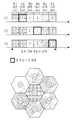
도 16을 참조하여, 기본 주파수 재사용 계수 3, 기준 부하율 2/3의 경우의 부분 대역 할당 시퀀스를 설명한다.Referring to Fig. 16, the partial band allocation sequence in the case of the basic
도 16은 기본 주파수 재사용 계수 3, 기준 부하율 2/3의 경우 준-직교 대역과 나머지 일반 부분 대역들의 셀간 간섭을 설명하기 위한 도면이다.16 is a diagram for explaining inter-cell interference of the quasi-orthogonal band and the remaining common partial bands in the case of the basic frequency reuse factor of 3 and the reference load factor of 2/3.
도 16을 참조하면, 각 셀(C1, C2 및 C3)에 있어서의 부분 대역들(제1 대역 내지 제6 대역)의 할당 순서가 나타나 있다. C1셀에서는 가장 먼저 할당되는 제2 부분 대역이 준-직교 기본 대역이 된다. 각 부분 대역의 크기가 동일한 경우 전술한 기준 부하율 조건에 따라 준-직교 기본 대역은 기준 부하율≤2/3 의 조건에서는 Tier-1 셀들에게 간섭을 유발하지 않는다. 다시 말해서,각 셀에서 4번째 시퀀스에 해당하는 부분 대역들이 할당될 때까지는 준-직교 기본 대역에서는 셀간의 간섭이 전혀 발생하지 않는다.Referring to FIG. 16, the allocation order of partial bands (first to sixth bands) in each of the cells C1, C2, and C3 is shown. In the cell C1, the first partial band allocated first is the quasi-orthogonal base band. If the sub-bands are of the same size, the quasi-orthogonal baseband does not cause interference to the Tier-1 cells under the condition of the reference load ratio? 2/3 according to the reference load rate condition described above. In other words, no inter-cell interference occurs in the quasi-orthogonal base band until partial bands corresponding to the fourth sequence are allocated in each cell.
또한, 도 17을 참조하여, 기본 주파수 재사용 계수 4, 기준 부하율 5/8의 경우의 부분 대역 할당 시퀀스를 설명한다.17, the partial band allocation sequence in the case of the basic frequency reuse factor of 4 and the reference load factor of 5/8 will be described.
도 17은 기본 주파수 재사용 계수 4, 기준 부하율 5/8의 경우 준-직교 대역과 나머지 일반 부분 대역들의 셀간 간섭을 설명하기 위한 도면이다.FIG. 17 is a view for explaining inter-cell interference of the quasi-orthogonal band and the remaining common partial bands when the basic frequency reuse factor is 4 and the reference load factor is 5/8.
도 17을 참조하면, 각 셀(C1, C2, C3, C4)에 있어서의 부분 대역들(제1 대역 내지 제8 대역)의 할당 순서가 나타나 있다. C1셀에서는 가장 먼저 할당되는 제1 부분 대역이 준-직교 기본 대역이 된다. C2 셀에서는 가장 먼저 할당되는 제3 부분 대역이 준-직교 기본 대역이 된다. C3 셀에서는 가장 먼저 할당되는 제5 부분 대역이 준-직교 기본 대역이 된다. C4 셀에서는 가장 먼저 할당되는 제7 부분 대역이 준-직교 기본 대역이 된다.Referring to Fig. 17, the order of allocation of partial bands (first to eighth bands) in each of the cells C1, C2, C3, and C4 is shown. In the cell C1, the first sub-band allocated first is the quasi-orthogonal basis band. In the C2 cell, the first sub-band allocated first is the quasi-orthogonal basis band. In the cell C3, the first partial band allocated first is the quasi-orthogonal base band. In the C4 cell, the seventh partial band allocated first is the quasi-orthogonal base band.
각 부분 대역의 크기가 동일한 경우 전술한 기준 부하율 조건에 따라 준-직 교 기본 대역은 기준 부하율, 즉 LF(Loading Factor)≤5/8 의 조건에서는 Tier-1 셀들에게 간섭을 유발하지 않는다. 다시 말해서,각 셀에서 5번째 시퀀스에 해당하는 부분 대역들이 할당될 때까지는 준-직교 기본 대역에서는 셀간의 간섭이 전혀 발생하지 않는다.If the size of each subband is the same, the quasi-orthogonal baseband does not cause interference to Tier-1 cells under the reference load factor, ie, Loading Factor ≤ 5/8, according to the reference load rate condition described above. In other words, no inter-cell interference occurs in the quasi-orthogonal base band until partial bands corresponding to the fifth sequence are allocated in each cell.
준-직교 기본 대역은 기본 주파수 재사용 구조에 해당하는 부하율 이하에서는 셀간 간섭이 기본 주파수 재사용 구조를 만족하기 때문에 이에 부합되는 간섭 구조를 갖는다. 따라서, 기본 주파수 재사용 구조에서의 최대 수용 가능한 부하율 이상으로 사용하는 경우, 추가적인 부분 대역 이용으로 말미암아 중심 셀이 간섭을 유발하는 셀들은 도 18에서와 같이 증가하게 된다.The quasi-orthogonal baseband has an interference structure that satisfies the fundamental frequency reuse structure because the inter-cell interference satisfies the basic frequency reuse structure below the load factor corresponding to the basic frequency reuse structure. Therefore, when using the maximum allowable load ratio in the basic frequency reuse structure, the cells causing the interference of the center cell due to the use of the additional partial band are increased as shown in FIG.
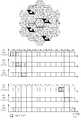
도 18은 기본 주파수 재사용 계수가 3이고 기준 부하율이 2/3인 경우에 부하율 증가에 따른 점진적인 간섭 셀의 증가 개념도를 나타낸 도면이다.18 is a diagram showing a conceptual diagram of an increment of interference cells due to an increase in load factor when the basic frequency reuse factor is 3 and the reference load factor is 2/3.
예를 들어, M=2인 경우, 기본 주파수 재사용 계수(Frequency Reuse Factor)가 3이면 기준 부하율은 2/3가 된다. 도 18(a)를 참조하면, 부하율이 2/3 이하인 경우에 각 셀에서 준-직교 기본 대역(예컨대, 도 16에서 C1 셀에서는 제2 대역, C2 셀에서는 제4 대역, 및 C3 셀에서는 제6 대역)에서는 셀간의 간섭이 전혀 발생하지 않는다. 도 18(b)를 참조하면, 부하율이 5/6 이하인 경우에는 예컨대, C1 셀의 준-직교 기본 대역이 C2셀에 할당되므로, C1 셀의 준-직교 기본 대역에서 C2 셀과의 간섭이 발생하게 된다. 유사하게, 도 18(c)를 참조하면, 부하율이 6/6 이하인 경우에는 예컨대, C1 셀의 준-직교 기본 대역이 C2셀 뿐 아니라 C3 셀에 할당되므로, C1 셀의 준-직교 기본 대역에서 C2 셀 및 C3 셀과의 간섭이 발생하게 된다.For example, in the case of M = 2, if the basic frequency reuse factor is 3, the reference load factor becomes 2/3. Referring to Fig. 18 (a), when a load factor is 2/3 or less, a quasi-orthogonal basis band (for example, the second band in C1 cell, the fourth band in C2 cell, 6 bands), interference between cells does not occur at all. 18B, when the load factor is 5/6 or less, for example, since the quasi-orthogonal base band of the C1 cell is allocated to the C2 cell, interference with the C2 cell occurs in the quasi-orthogonal base band of the C1 cell . Similarly, referring to FIG. 18 (c), when the load factor is 6/6 or less, for example, since the quasi-orthogonal base band of the C1 cell is allocated to the C3 cell as well as the C2 cell, C2, and C3 cells.
전술한 바와 같이, 부분 대역 할당 시퀀스가 설정된 후 단계 150에서 설정된 대역 할당 시퀀스에 따라 사용자로부터의 서비스 요청시 부분 대역들이 각 셀에 할당된다. 예컨대, 각 셀에서 새로운 사용자가 서비스를 요구하면, 기지국은 준-직교 기본 대역에 우선적으로 할당하며, 준-직교 기본 대역 중의 임의의 빈 부채널을 사용자에게 할당할 수 있다.As described above, after the partial band allocation sequence is set, partial bands are assigned to each cell when a service is requested from the user according to the band allocation sequence set in
또한, 부분 대역의 할당시, SINR, 사용자의 요구 신호 품질 등이 고려될 수 있다.In allocating the partial bands, the SINR, the quality of the request signal of the user, and the like can be considered.
SINR을 고려하면, 준-직교 기본 대역은 인접 셀간 간섭이 상대적으로 낮게 유지되므로 SINR이 낮은 셀-경계 사용자들에게 우선 할당될 수 있다. 따라서 기지국은 부분 대역 할당 과정에서 사용자들을 SINR이 낮은 순서대로 정렬하고, SINR이 낮은 사용자들부터 준-직교 기본 대역에 할당한다. 선택적으로, 기지국은 주기적으로 다시 SINR을 평가하여 SINR이 상대적으로 낮은 사용자들은 준-직교 기본 대역으로 이동시킬 수 있으며, SINR이 상대적으로 높은 준-직교 기본 대역 크기를 초과하는 사용자들은 일반 부분 대역으로 이동시킬 수 있다.Considering the SINR, the quasi-orthogonal basis band can be allocated first to cell-boundary users with low SINRs because the inter-cell interference is kept relatively low. Therefore, the BS allocates the users to the quasi-orthogonal baseband from the users with low SINRs in the order of the lowest SINR in the partial band allocation process. Optionally, the base station may periodically re-evaluate the SINR to allow users with relatively low SINRs to move to the quasi-orthogonal base band, and users whose SINR exceeds the relatively high quasi-orthogonal baseband size may use a common partial band Can be moved.
사용자의 요구 신호 품질을 고려하면, 준-직교 기본 대역은 인접 셀간 간섭이 상대적으로 낮게 유지되므로 높은 신호 품질을 유지해야 하는 사용자들이나 추가적으로 성능 개선이 많이 필요한 사용자들에게 우선 할당될 수 있다.Considering the quality of the request signal of the user, the quasi-orthogonal base band can be allocated first to users who need to maintain high signal quality or users who need to further improve performance because inter-cell interference is kept relatively low.
이와 같이, 부분 대역의 할당 과정에서 사용자들의 요구 신호 품질과 SINR을 고려하여, 높은 신호 품질을 요구하는 사용자나 SINR이 낮은 사용자들에게 우선적으로 준-직교 기본 대역이 할당될 수 있다.In this way, in consideration of users' request signal quality and SINR in the process of allocating the partial bands, quasi-orthogonal base band can be preferentially allocated to users requesting high signal quality or users having low SINR.
이하에서는 시퀀스 설정 방법을 좀 더 상세히 설명한다.Hereinafter, the sequence setting method will be described in more detail.
본 발명의 실시예에 따라 대역 할당 시퀀스는 크게 준-직교 기본 대역 할당을 위한 시퀀스와 일반 부분 대역 할당을 위한 시퀀스로 구분하여 설계할 수 있다.According to the embodiment of the present invention, the bandwidth allocation sequence can be divided into a sequence for quasi-orthogonal base band allocation and a sequence for general partial bandwidth allocation.
일반적으로 준-직교 기본 대역은 설정한 인접한 셀의 수에 따라 그 시퀀스의 길이가 달라진다. 인접한 N개 셀 사이의 준-직교 대역을 설정하면, 기준 부하율 이하에서는 해당 대역들 사이에 간섭이 발생하지 않아야 한다. 이때 준-직교 기본 대역 시퀀스의 길이는 N이 되며, 각 셀에 준-직교 기본 대역을 할당하기 위하여 부분 대역이 한 단계씩 이동되는 순환 시퀀스가 설정될 수 있다.Generally, the length of the quasi-orthogonal base band varies depending on the number of adjacent cells set. If quasi-orthogonal bands are set between adjacent N cells, interference should not occur between the bands below the reference load ratio. In this case, the length of the quasi-orthogonal basic band sequence is N, and a circular sequence in which the partial bands are shifted by one step may be set in order to allocate a quasi-orthogonal basis band to each cell.
실제 구현 예(기본 주파수 재사용 계수 4의 경우=인접한 4개 셀 사이의 준-직교 기본 대역 설정)Actual implementation example (in case of basic

이때 각 셀들을 위하여 처음으로 할당되는 부분 대역들이 해당 셀의 준-직교 기본 대역으로 설정되며, 준-직교 기본 대역 시퀀스의 나머지 부분 대역들은 인접한 셀들의 준-직교 기본 대역들에 상호 간섭을 유발하기 때문에 일반 부분 대역의 할당 후 마지막으로 할당된다.At this time, the first sub-bands allocated to each cell are set as the quasi-orthogonal base band of the corresponding cell, and the remaining partial bands of the quasi-orthogonal basic band sequence cause mutual interference to the quasi-orthogonal base bands of adjacent cells Therefore, it is finally allocated after allocation of the common partial band.
한편, 분할 결과에 따른 부분 대역들의 총수는 기본 주파수 재사용 계수의 정수배가 되기 때문에 준-직교 기본 대역 시퀀스의 길이가 N이라면 일반 부분 대역의 수는 N의 정수배가 된다. 일반 부분 대역 할당시 인접한 셀 사이의 간섭이 평균적으로 증가해야 하기 때문에, 소정의 할당 시퀀스에서 부분 대역이 한 단계씩 이동된 시퀀스가 각 셀을 위해 설정될 수 있다.On the other hand, since the total number of partial bands according to the division result is an integer multiple of the basic frequency reuse coefficient, the number of general partial bands becomes an integral multiple of N when the length of the quasi-orthogonal base band sequence is N. [ Since the interference between neighboring cells should increase on average in the general partial band allocation, a sequence in which the partial bands are shifted by one step in a predetermined allocation sequence may be set for each cell.
실제 구현 예 (기본 주파수 재사용 계수 4의 경우=4개의 일반 부분 대역이 있는 경우)Actual Implementation Example (In case of the basic

전술한 준-직교 기본 대역의 할당 시퀀스 및 일반 부분 대역의 할당 시퀀스는 결합될 수 있으며, 그에 따른 각 셀의 부분 대역 할당 시퀀스는 도 19와 같이 구성될 수 있다.The allocation sequence of the quasi-orthogonal base band and the allocation sequence of the general partial band described above may be combined, and the partial band allocation sequence of each cell accordingly can be configured as shown in FIG.
도 19는 부분 대역 할당을 위한 전체 시퀀스 설계 원리를 나타낸 도면이다.19 is a diagram illustrating the entire sequence design principle for partial band allocation.
도 19를 참조하면, 각 셀의 준-직교 기본 대역 시퀀스의 맨 처음 부분 대역들이 해당 셀의 준-직교 대역으로 선택된다. 이어서, 각 셀의 일반 부분 대역 할당 시퀀스가 결합된다. 마지막으로, 각 셀의 준-직교 기본 대역을 제외한 나머지 준-직교 기본 대역 시퀀스가 결합된다.Referring to FIG. 19, the first subbands of the quasi-orthogonal baseband sequence of each cell are selected as quasi-orthogonal bands of the corresponding cell. Then, the general partial band allocation sequence of each cell is combined. Finally, the quasi-orthogonal base band sequences except for the quasi-orthogonal base band of each cell are combined.
이와 같이, 본 발명에서는 분할된 부분 대역들의 이용 순서를 제어함으로써, 주파수 재사용 계수 1을 유지하면서 인접 셀들로부터의 간섭을 최대한 낮게 유지할 수 있는 준-직교 기본 대역을 형성할 수 있도록 하였다. 다시 말하면, 기준 부하율 이하에서는 중심 셀 준-직교 대역이 인접한 셀들 각각의 준-직교 기본 대역들에 간섭을 야기시키지 않도록 설정하였다. 이러한 준-직교 기본 대역을 신호 특성이 나쁜 셀-경계 사용자들에게 우선적으로 할당함으로써, 셀-경계 사용자 성능을 크게 향상시킬 뿐만 아니라 전체적인 시스템 성능을 향상시킬 수 있다. 또한 본 발명은 주파수 재사용 계수 1 기반의 유연한 자원 이용 구조이기 때문에, 부분 대역 이용 순서를 조정함으로써 전통적인 주파수 재사용 기법(예: FRF=3, 4, 7 …)으로 운용할 수 있고, 일부 대역의 할당 순서와 셀간 간섭 관계를 조정함으로써 SFR, FFR 기법 등 다양한 주파수 재사용 방식들로의 운용도 가능하다.As described above, according to the present invention, the quasi-orthogonal base band that can maintain the interference from the adjacent cells as low as possible while maintaining the frequency reuse factor of 1 can be formed by controlling the order of use of the divided partial bands. In other words, below the reference load ratio, the center cell quasi-orthogonal band is set not to cause interference to the quasi-orthogonal base bands of adjacent cells. By assigning such a quasi-orthogonal base band preferentially to the bad cell-boundary users, the cell-boundary user performance can be greatly improved and the overall system performance can be improved. In addition, since the present invention is a flexible resource utilization structure based on the
도 1a는 본 발명의 실시예에 따른 제1타입 세그먼트 사용 방식을 도시한 도면1A is a diagram illustrating a method of using a first type segment according to an embodiment of the present invention;
도 1b는 본 발명의 실시예에 따른 제2타입 세그먼트 사용 방식을 도시한 도면1B is a diagram illustrating a method of using a second type segment according to an embodiment of the present invention.
도 1c는 본 발명의 실시예에 따른 세그먼트 단위로 송신 전력을 제어하는 방식을 도시한 도면1C is a diagram illustrating a method of controlling transmission power in a segment unit according to an embodiment of the present invention
도 2는 본 발명의 실시예에 따른 주파수 자원 사용 시퀀스를 사용하여 주파수 자원을 사용하는 동작을 개략적으로 도시한 도면2 is a diagram schematically illustrating an operation of using a frequency resource using a frequency resource use sequence according to an embodiment of the present invention;
도 3은 본 발명의 실시예에 따라 각 셀에서 사용하는 세그먼트 시퀀스의 종류와 기존 주파수 재사용 계수가 동일할 경우의 세그먼트 시퀀스들을 도시한 도면3 is a diagram illustrating segment sequences when the types of segment sequences used in each cell and the existing frequency reuse factor are the same according to an embodiment of the present invention.
도 4는 본 발명의 실시예에 따라 각 셀에서 사용하는 세그먼트 시퀀스의 종류와 섹터화 계수가 동일할 경우의 세그먼트 시퀀스들을 도시한 도면FIG. 4 is a diagram showing segment sequences when the types of segment sequences used in each cell are equal to the sectorization coefficients according to an embodiment of the present invention. FIG.
도 5는 본 발명의 실시예에 따른 기존 주파수 재사용 계수 3을 사용하고, 제1타입 세그먼트 사용 방식을 하고, 전방향 셀 구조를 사용할 경우의 IFR 방식을 도시한 도면FIG. 5 is a diagram illustrating an IFR scheme using a conventional
도 6은 본 발명의 실시예에 따른 기존 주파수 재사용 계수 3을 사용하고, 제2타입 세그먼트 사용 방식을 사용하고, 전방향 셀 구조를 사용할 경우의 IFR 방식을 도시한 도면FIG. 6 is a diagram illustrating an IFR scheme using an existing
도 7은 본 발명의 실시예에 따른 기존 주파수 재사용 계수 3을 사용하고, 제1타입 세그먼트 사용 방식을 하고, 섹터 셀 구조를 사용할 경우의 IFR 방식을 도시한 도면FIG. 7 is a diagram illustrating an IFR scheme using a conventional
도 8은 본 발명의 실시예에 따른 기존 주파수 재사용 계수 4를 사용하고, 제1타입 세그먼트 사용 방식을 하고, 전방향 셀 구조를 사용할 경우의 IFR 방식을 도시한 도면FIG. 8 is a diagram illustrating an IFR scheme in which a conventional
도 9는 본 발명의 실시예에 따른 기존 주파수 재사용 계수 4를 사용하고, 제2타입 세그먼트 사용 방식을 사용하고, 전방향 셀 구조를 사용할 경우의 IFR 방식의 제1예를 도시한 도면9 is a diagram showing a first example of an IFR scheme in which a conventional
도 10은 본 발명의 실시예에 따른 기존 주파수 재사용 계수 4를 사용하고, 제2타입 세그먼트 사용 방식을 사용하고, 전방향 셀 구조를 사용할 경우의 IFR 방식의 제2예를 도시한 도면10 is a diagram showing a second example of an IFR scheme using an existing
도 11은 본 발명의 실시예에 따른 기존 주파수 재사용 계수 4를 사용하고, 제2타입 세그먼트 사용 방식을 사용하고, 전방향 셀 구조를 사용할 경우의 IFR 방식의 제3예를 도시한 도면11 is a diagram showing a third example of an IFR scheme using an existing
도 12는 본 발명의 실시예에 따른 기존 주파수 재사용 계수 4를 사용하고, 제1타입 세그먼트 사용 방식을 하고, 섹터 셀 구조를 사용할 경우의 IFR 방식을 도시한 도면FIG. 12 is a diagram illustrating an IFR scheme using a conventional
도 13은 본 발명의 실시예에 따른 기존 주파수 재사용 계수 7을 사용하고, 제1타입 세그먼트 사용 방식을 하고, 전방향 셀 구조를 사용할 경우의 IFR 방식을 도시한 도면FIG. 13 is a diagram illustrating an IFR scheme in which a conventional
도 14는 본 발명에 따른 준 직교 기본 대역을 설명하기 위한 도면14 is a view for explaining a quasi-orthogonal basic band according to the present invention;
도 15는 본 발명의 실시예에 따른 주파수 자원 사용 방법을 나타낸 흐름도15 is a flowchart illustrating a method of using a frequency resource according to an embodiment of the present invention.
도 16은 기본 주파수 재사용 계수 3, 기준 부하율 2/3의 경우 준-직교 대역과 나머지 일반 부분 대역들의 셀간 간섭을 설명하기 위한 도면16 is a diagram for explaining the inter-cell interference of the quasi-orthogonal band and the remaining common partial bands in the case of the basic
도 17은 기본 주파수 재사용 계수 4, 기준 부하율 5/8의 경우 준-직교 대역과 나머지 일반 부분 대역들의 셀간 간섭을 설명하기 위한 도면17 is a diagram for explaining the inter-cell interference of the quasi-orthogonal band and the remaining common partial bands when the fundamental frequency reuse factor is 4 and the reference load factor is 5/8;
도 18은 기본 주파수 재사용 계수가 3이고 기준 부하율이 2/3인 경우에 부하율 증가에 따른 점진적인 간섭 셀의 증가 개념도를 나타낸 도면18 is a diagram showing a conceptual diagram of an incremental interference cell increment with increasing load factor when the basic frequency reuse factor is 3 and the reference load factor is 2/3;
도 19는 부분 대역 할당을 위한 전체 시퀀스 설계 원리를 나타낸 도면19 is a diagram showing an overall sequence design principle for partial band allocation;
Claims (30)
Translated fromKoreanPriority Applications (1)
| Application Number | Priority Date | Filing Date | Title |
|---|---|---|---|
| US12/188,159US8204012B2 (en) | 2007-08-09 | 2008-08-07 | System and method for using frequency resource in communication system |
Applications Claiming Priority (2)
| Application Number | Priority Date | Filing Date | Title |
|---|---|---|---|
| KR1020070080314 | 2007-08-09 | ||
| KR20070080314 | 2007-08-09 |
Publications (2)
| Publication Number | Publication Date |
|---|---|
| KR20090015781A KR20090015781A (en) | 2009-02-12 |
| KR101421297B1true KR101421297B1 (en) | 2014-07-18 |
Family
ID=40685297
Family Applications (1)
| Application Number | Title | Priority Date | Filing Date |
|---|---|---|---|
| KR1020080003185AExpired - Fee RelatedKR101421297B1 (en) | 2007-08-09 | 2008-01-10 | Systems and methods for using frequency resources in communication systems |
Country Status (1)
| Country | Link |
|---|---|
| KR (1) | KR101421297B1 (en) |
Families Citing this family (1)
| Publication number | Priority date | Publication date | Assignee | Title |
|---|---|---|---|---|
| KR101633109B1 (en)* | 2009-11-27 | 2016-06-24 | 삼성전자주식회사 | Scheduling apparatus in a multi-cell communication systemand method thereof |
Citations (3)
| Publication number | Priority date | Publication date | Assignee | Title |
|---|---|---|---|---|
| US6907246B2 (en)* | 2001-11-20 | 2005-06-14 | Navini Networks, Inc. | Method and system for reducing wireless multi-cell interferences through segregated channel assignments and segregated antenna beams |
| KR20060094435A (en)* | 2005-02-24 | 2006-08-29 | 삼성전자주식회사 | Frequency Resource Allocation System and Method in a Multi-Cell Communication System |
| KR20080064122A (en)* | 2005-10-07 | 2008-07-08 | 삼성전자주식회사 | Multicarrier wireless network with flexible partial frequency reuse |
- 2008
- 2008-01-10KRKR1020080003185Apatent/KR101421297B1/ennot_activeExpired - Fee Related
Patent Citations (3)
| Publication number | Priority date | Publication date | Assignee | Title |
|---|---|---|---|---|
| US6907246B2 (en)* | 2001-11-20 | 2005-06-14 | Navini Networks, Inc. | Method and system for reducing wireless multi-cell interferences through segregated channel assignments and segregated antenna beams |
| KR20060094435A (en)* | 2005-02-24 | 2006-08-29 | 삼성전자주식회사 | Frequency Resource Allocation System and Method in a Multi-Cell Communication System |
| KR20080064122A (en)* | 2005-10-07 | 2008-07-08 | 삼성전자주식회사 | Multicarrier wireless network with flexible partial frequency reuse |
Also Published As
| Publication number | Publication date |
|---|---|
| KR20090015781A (en) | 2009-02-12 |
Similar Documents
| Publication | Publication Date | Title |
|---|---|---|
| US9609650B2 (en) | Adaptive uplink/downlink timeslot assignment in a hybrid wireless time division multiple access/code division multiple access communication system | |
| JP4740267B2 (en) | Band distributed resource allocation method and apparatus in orthogonal frequency division multiple access system | |
| US8391877B2 (en) | Measurement-assisted dynamic frequency-reuse in cellular telecommunications networks | |
| US8825071B2 (en) | Resource allocation in a radio communication system | |
| US6788943B1 (en) | Channel allocation in the base stations of a cellular radio system | |
| EP2139249B1 (en) | Base station and method used in mobile communication system | |
| US5835859A (en) | Method for frequency allocation and assignment in wireless communication systems | |
| AU2001297547A1 (en) | Adaptive uplink/downlink timeslot assignment in a hybrid wireless time division multiple access/code division multiple access communication system | |
| US9578622B2 (en) | Method for allocating resources | |
| KR20060097450A (en) | System and method for resource allocation control in multi-cell communication system | |
| JP2010226712A (en) | Inter-cell interference prediction for frequency resource allocation | |
| KR20080029734A (en) | Resource Allocation Method for Uplink Control Channel | |
| KR20050032796A (en) | Method for controlling the loading to increase system throughput in wireless packet cellular network | |
| KR100800657B1 (en) | Power control apparatus and method in cellular system using wired relay station | |
| US8204012B2 (en) | System and method for using frequency resource in communication system | |
| KR101421297B1 (en) | Systems and methods for using frequency resources in communication systems | |
| US6845086B1 (en) | Cellular congestion reduction via intracell handover providing fixed and flexible service | |
| CN102067650A (en) | Wireless communication system, base station, channel allocation method and program |
Legal Events
| Date | Code | Title | Description |
|---|---|---|---|
| PA0109 | Patent application | St.27 status event code:A-0-1-A10-A12-nap-PA0109 | |
| R18-X000 | Changes to party contact information recorded | St.27 status event code:A-3-3-R10-R18-oth-X000 | |
| PG1501 | Laying open of application | St.27 status event code:A-1-1-Q10-Q12-nap-PG1501 | |
| R18-X000 | Changes to party contact information recorded | St.27 status event code:A-3-3-R10-R18-oth-X000 | |
| A201 | Request for examination | ||
| E13-X000 | Pre-grant limitation requested | St.27 status event code:A-2-3-E10-E13-lim-X000 | |
| P11-X000 | Amendment of application requested | St.27 status event code:A-2-2-P10-P11-nap-X000 | |
| P13-X000 | Application amended | St.27 status event code:A-2-2-P10-P13-nap-X000 | |
| PA0201 | Request for examination | St.27 status event code:A-1-2-D10-D11-exm-PA0201 | |
| E902 | Notification of reason for refusal | ||
| PE0902 | Notice of grounds for rejection | St.27 status event code:A-1-2-D10-D21-exm-PE0902 | |
| E13-X000 | Pre-grant limitation requested | St.27 status event code:A-2-3-E10-E13-lim-X000 | |
| P11-X000 | Amendment of application requested | St.27 status event code:A-2-2-P10-P11-nap-X000 | |
| P13-X000 | Application amended | St.27 status event code:A-2-2-P10-P13-nap-X000 | |
| E701 | Decision to grant or registration of patent right | ||
| PE0701 | Decision of registration | St.27 status event code:A-1-2-D10-D22-exm-PE0701 | |
| GRNT | Written decision to grant | ||
| PR0701 | Registration of establishment | St.27 status event code:A-2-4-F10-F11-exm-PR0701 | |
| PR1002 | Payment of registration fee | St.27 status event code:A-2-2-U10-U11-oth-PR1002 Fee payment year number:1 | |
| PG1601 | Publication of registration | St.27 status event code:A-4-4-Q10-Q13-nap-PG1601 | |
| R18-X000 | Changes to party contact information recorded | St.27 status event code:A-5-5-R10-R18-oth-X000 | |
| R18-X000 | Changes to party contact information recorded | St.27 status event code:A-5-5-R10-R18-oth-X000 | |
| FPAY | Annual fee payment | Payment date:20170629 Year of fee payment:4 | |
| PR1001 | Payment of annual fee | St.27 status event code:A-4-4-U10-U11-oth-PR1001 Fee payment year number:4 | |
| FPAY | Annual fee payment | Payment date:20180628 Year of fee payment:5 | |
| PR1001 | Payment of annual fee | St.27 status event code:A-4-4-U10-U11-oth-PR1001 Fee payment year number:5 | |
| PC1903 | Unpaid annual fee | St.27 status event code:A-4-4-U10-U13-oth-PC1903 Not in force date:20190715 Payment event data comment text:Termination Category : DEFAULT_OF_REGISTRATION_FEE | |
| PC1903 | Unpaid annual fee | St.27 status event code:N-4-6-H10-H13-oth-PC1903 Ip right cessation event data comment text:Termination Category : DEFAULT_OF_REGISTRATION_FEE Not in force date:20190715 | |
| P22-X000 | Classification modified | St.27 status event code:A-4-4-P10-P22-nap-X000 | |
| P22-X000 | Classification modified | St.27 status event code:A-4-4-P10-P22-nap-X000 |