KR101420340B1 - Vehicle operating system and method for controlling the same - Google Patents
Vehicle operating system and method for controlling the sameDownload PDFInfo
- Publication number
- KR101420340B1 KR101420340B1KR1020120030235AKR20120030235AKR101420340B1KR 101420340 B1KR101420340 B1KR 101420340B1KR 1020120030235 AKR1020120030235 AKR 1020120030235AKR 20120030235 AKR20120030235 AKR 20120030235AKR 101420340 B1KR101420340 B1KR 101420340B1
- Authority
- KR
- South Korea
- Prior art keywords
- battery
- fan
- control unit
- power
- cooling
- Prior art date
- Legal status (The legal status is an assumption and is not a legal conclusion. Google has not performed a legal analysis and makes no representation as to the accuracy of the status listed.)
- Expired - Fee Related
Links
Images


Classifications
- B—PERFORMING OPERATIONS; TRANSPORTING
- B60—VEHICLES IN GENERAL
- B60W—CONJOINT CONTROL OF VEHICLE SUB-UNITS OF DIFFERENT TYPE OR DIFFERENT FUNCTION; CONTROL SYSTEMS SPECIALLY ADAPTED FOR HYBRID VEHICLES; ROAD VEHICLE DRIVE CONTROL SYSTEMS FOR PURPOSES NOT RELATED TO THE CONTROL OF A PARTICULAR SUB-UNIT
- B60W10/00—Conjoint control of vehicle sub-units of different type or different function
- B60W10/24—Conjoint control of vehicle sub-units of different type or different function including control of energy storage means
- B60W10/26—Conjoint control of vehicle sub-units of different type or different function including control of energy storage means for electrical energy, e.g. batteries or capacitors
- B—PERFORMING OPERATIONS; TRANSPORTING
- B60—VEHICLES IN GENERAL
- B60L—PROPULSION OF ELECTRICALLY-PROPELLED VEHICLES; SUPPLYING ELECTRIC POWER FOR AUXILIARY EQUIPMENT OF ELECTRICALLY-PROPELLED VEHICLES; ELECTRODYNAMIC BRAKE SYSTEMS FOR VEHICLES IN GENERAL; MAGNETIC SUSPENSION OR LEVITATION FOR VEHICLES; MONITORING OPERATING VARIABLES OF ELECTRICALLY-PROPELLED VEHICLES; ELECTRIC SAFETY DEVICES FOR ELECTRICALLY-PROPELLED VEHICLES
- B60L1/00—Supplying electric power to auxiliary equipment of vehicles
- B60L1/003—Supplying electric power to auxiliary equipment of vehicles to auxiliary motors, e.g. for pumps, compressors
- B—PERFORMING OPERATIONS; TRANSPORTING
- B60—VEHICLES IN GENERAL
- B60L—PROPULSION OF ELECTRICALLY-PROPELLED VEHICLES; SUPPLYING ELECTRIC POWER FOR AUXILIARY EQUIPMENT OF ELECTRICALLY-PROPELLED VEHICLES; ELECTRODYNAMIC BRAKE SYSTEMS FOR VEHICLES IN GENERAL; MAGNETIC SUSPENSION OR LEVITATION FOR VEHICLES; MONITORING OPERATING VARIABLES OF ELECTRICALLY-PROPELLED VEHICLES; ELECTRIC SAFETY DEVICES FOR ELECTRICALLY-PROPELLED VEHICLES
- B60L3/00—Electric devices on electrically-propelled vehicles for safety purposes; Monitoring operating variables, e.g. speed, deceleration or energy consumption
- B60L3/0023—Detecting, eliminating, remedying or compensating for drive train abnormalities, e.g. failures within the drive train
- B60L3/0046—Detecting, eliminating, remedying or compensating for drive train abnormalities, e.g. failures within the drive train relating to electric energy storage systems, e.g. batteries or capacitors
- B—PERFORMING OPERATIONS; TRANSPORTING
- B60—VEHICLES IN GENERAL
- B60L—PROPULSION OF ELECTRICALLY-PROPELLED VEHICLES; SUPPLYING ELECTRIC POWER FOR AUXILIARY EQUIPMENT OF ELECTRICALLY-PROPELLED VEHICLES; ELECTRODYNAMIC BRAKE SYSTEMS FOR VEHICLES IN GENERAL; MAGNETIC SUSPENSION OR LEVITATION FOR VEHICLES; MONITORING OPERATING VARIABLES OF ELECTRICALLY-PROPELLED VEHICLES; ELECTRIC SAFETY DEVICES FOR ELECTRICALLY-PROPELLED VEHICLES
- B60L3/00—Electric devices on electrically-propelled vehicles for safety purposes; Monitoring operating variables, e.g. speed, deceleration or energy consumption
- B60L3/04—Cutting off the power supply under fault conditions
- B—PERFORMING OPERATIONS; TRANSPORTING
- B60—VEHICLES IN GENERAL
- B60L—PROPULSION OF ELECTRICALLY-PROPELLED VEHICLES; SUPPLYING ELECTRIC POWER FOR AUXILIARY EQUIPMENT OF ELECTRICALLY-PROPELLED VEHICLES; ELECTRODYNAMIC BRAKE SYSTEMS FOR VEHICLES IN GENERAL; MAGNETIC SUSPENSION OR LEVITATION FOR VEHICLES; MONITORING OPERATING VARIABLES OF ELECTRICALLY-PROPELLED VEHICLES; ELECTRIC SAFETY DEVICES FOR ELECTRICALLY-PROPELLED VEHICLES
- B60L50/00—Electric propulsion with power supplied within the vehicle
- B60L50/50—Electric propulsion with power supplied within the vehicle using propulsion power supplied by batteries or fuel cells
- B60L50/60—Electric propulsion with power supplied within the vehicle using propulsion power supplied by batteries or fuel cells using power supplied by batteries
- B60L50/61—Electric propulsion with power supplied within the vehicle using propulsion power supplied by batteries or fuel cells using power supplied by batteries by batteries charged by engine-driven generators, e.g. series hybrid electric vehicles
- B60L50/62—Electric propulsion with power supplied within the vehicle using propulsion power supplied by batteries or fuel cells using power supplied by batteries by batteries charged by engine-driven generators, e.g. series hybrid electric vehicles charged by low-power generators primarily intended to support the batteries, e.g. range extenders
- B—PERFORMING OPERATIONS; TRANSPORTING
- B60—VEHICLES IN GENERAL
- B60L—PROPULSION OF ELECTRICALLY-PROPELLED VEHICLES; SUPPLYING ELECTRIC POWER FOR AUXILIARY EQUIPMENT OF ELECTRICALLY-PROPELLED VEHICLES; ELECTRODYNAMIC BRAKE SYSTEMS FOR VEHICLES IN GENERAL; MAGNETIC SUSPENSION OR LEVITATION FOR VEHICLES; MONITORING OPERATING VARIABLES OF ELECTRICALLY-PROPELLED VEHICLES; ELECTRIC SAFETY DEVICES FOR ELECTRICALLY-PROPELLED VEHICLES
- B60L58/00—Methods or circuit arrangements for monitoring or controlling batteries or fuel cells, specially adapted for electric vehicles
- B60L58/10—Methods or circuit arrangements for monitoring or controlling batteries or fuel cells, specially adapted for electric vehicles for monitoring or controlling batteries
- B60L58/12—Methods or circuit arrangements for monitoring or controlling batteries or fuel cells, specially adapted for electric vehicles for monitoring or controlling batteries responding to state of charge [SoC]
- B60L58/14—Preventing excessive discharging
- B—PERFORMING OPERATIONS; TRANSPORTING
- B60—VEHICLES IN GENERAL
- B60L—PROPULSION OF ELECTRICALLY-PROPELLED VEHICLES; SUPPLYING ELECTRIC POWER FOR AUXILIARY EQUIPMENT OF ELECTRICALLY-PROPELLED VEHICLES; ELECTRODYNAMIC BRAKE SYSTEMS FOR VEHICLES IN GENERAL; MAGNETIC SUSPENSION OR LEVITATION FOR VEHICLES; MONITORING OPERATING VARIABLES OF ELECTRICALLY-PROPELLED VEHICLES; ELECTRIC SAFETY DEVICES FOR ELECTRICALLY-PROPELLED VEHICLES
- B60L58/00—Methods or circuit arrangements for monitoring or controlling batteries or fuel cells, specially adapted for electric vehicles
- B60L58/10—Methods or circuit arrangements for monitoring or controlling batteries or fuel cells, specially adapted for electric vehicles for monitoring or controlling batteries
- B60L58/12—Methods or circuit arrangements for monitoring or controlling batteries or fuel cells, specially adapted for electric vehicles for monitoring or controlling batteries responding to state of charge [SoC]
- B60L58/15—Preventing overcharging
- B—PERFORMING OPERATIONS; TRANSPORTING
- B60—VEHICLES IN GENERAL
- B60L—PROPULSION OF ELECTRICALLY-PROPELLED VEHICLES; SUPPLYING ELECTRIC POWER FOR AUXILIARY EQUIPMENT OF ELECTRICALLY-PROPELLED VEHICLES; ELECTRODYNAMIC BRAKE SYSTEMS FOR VEHICLES IN GENERAL; MAGNETIC SUSPENSION OR LEVITATION FOR VEHICLES; MONITORING OPERATING VARIABLES OF ELECTRICALLY-PROPELLED VEHICLES; ELECTRIC SAFETY DEVICES FOR ELECTRICALLY-PROPELLED VEHICLES
- B60L58/00—Methods or circuit arrangements for monitoring or controlling batteries or fuel cells, specially adapted for electric vehicles
- B60L58/10—Methods or circuit arrangements for monitoring or controlling batteries or fuel cells, specially adapted for electric vehicles for monitoring or controlling batteries
- B60L58/24—Methods or circuit arrangements for monitoring or controlling batteries or fuel cells, specially adapted for electric vehicles for monitoring or controlling batteries for controlling the temperature of batteries
- B60L58/26—Methods or circuit arrangements for monitoring or controlling batteries or fuel cells, specially adapted for electric vehicles for monitoring or controlling batteries for controlling the temperature of batteries by cooling
- B—PERFORMING OPERATIONS; TRANSPORTING
- B60—VEHICLES IN GENERAL
- B60W—CONJOINT CONTROL OF VEHICLE SUB-UNITS OF DIFFERENT TYPE OR DIFFERENT FUNCTION; CONTROL SYSTEMS SPECIALLY ADAPTED FOR HYBRID VEHICLES; ROAD VEHICLE DRIVE CONTROL SYSTEMS FOR PURPOSES NOT RELATED TO THE CONTROL OF A PARTICULAR SUB-UNIT
- B60W10/00—Conjoint control of vehicle sub-units of different type or different function
- B60W10/24—Conjoint control of vehicle sub-units of different type or different function including control of energy storage means
- B—PERFORMING OPERATIONS; TRANSPORTING
- B60—VEHICLES IN GENERAL
- B60W—CONJOINT CONTROL OF VEHICLE SUB-UNITS OF DIFFERENT TYPE OR DIFFERENT FUNCTION; CONTROL SYSTEMS SPECIALLY ADAPTED FOR HYBRID VEHICLES; ROAD VEHICLE DRIVE CONTROL SYSTEMS FOR PURPOSES NOT RELATED TO THE CONTROL OF A PARTICULAR SUB-UNIT
- B60W50/00—Details of control systems for road vehicle drive control not related to the control of a particular sub-unit, e.g. process diagnostic or vehicle driver interfaces
- H—ELECTRICITY
- H01—ELECTRIC ELEMENTS
- H01M—PROCESSES OR MEANS, e.g. BATTERIES, FOR THE DIRECT CONVERSION OF CHEMICAL ENERGY INTO ELECTRICAL ENERGY
- H01M10/00—Secondary cells; Manufacture thereof
- H01M10/42—Methods or arrangements for servicing or maintenance of secondary cells or secondary half-cells
- H01M10/48—Accumulators combined with arrangements for measuring, testing or indicating the condition of cells, e.g. the level or density of the electrolyte
- H01M10/486—Accumulators combined with arrangements for measuring, testing or indicating the condition of cells, e.g. the level or density of the electrolyte for measuring temperature
- H—ELECTRICITY
- H01—ELECTRIC ELEMENTS
- H01M—PROCESSES OR MEANS, e.g. BATTERIES, FOR THE DIRECT CONVERSION OF CHEMICAL ENERGY INTO ELECTRICAL ENERGY
- H01M10/00—Secondary cells; Manufacture thereof
- H01M10/60—Heating or cooling; Temperature control
- H01M10/61—Types of temperature control
- H01M10/613—Cooling or keeping cold
- H—ELECTRICITY
- H01—ELECTRIC ELEMENTS
- H01M—PROCESSES OR MEANS, e.g. BATTERIES, FOR THE DIRECT CONVERSION OF CHEMICAL ENERGY INTO ELECTRICAL ENERGY
- H01M10/00—Secondary cells; Manufacture thereof
- H01M10/60—Heating or cooling; Temperature control
- H01M10/62—Heating or cooling; Temperature control specially adapted for specific applications
- H01M10/625—Vehicles
- H—ELECTRICITY
- H01—ELECTRIC ELEMENTS
- H01M—PROCESSES OR MEANS, e.g. BATTERIES, FOR THE DIRECT CONVERSION OF CHEMICAL ENERGY INTO ELECTRICAL ENERGY
- H01M10/00—Secondary cells; Manufacture thereof
- H01M10/60—Heating or cooling; Temperature control
- H01M10/65—Means for temperature control structurally associated with the cells
- H01M10/656—Means for temperature control structurally associated with the cells characterised by the type of heat-exchange fluid
- H01M10/6561—Gases
- H01M10/6563—Gases with forced flow, e.g. by blowers
- B—PERFORMING OPERATIONS; TRANSPORTING
- B60—VEHICLES IN GENERAL
- B60L—PROPULSION OF ELECTRICALLY-PROPELLED VEHICLES; SUPPLYING ELECTRIC POWER FOR AUXILIARY EQUIPMENT OF ELECTRICALLY-PROPELLED VEHICLES; ELECTRODYNAMIC BRAKE SYSTEMS FOR VEHICLES IN GENERAL; MAGNETIC SUSPENSION OR LEVITATION FOR VEHICLES; MONITORING OPERATING VARIABLES OF ELECTRICALLY-PROPELLED VEHICLES; ELECTRIC SAFETY DEVICES FOR ELECTRICALLY-PROPELLED VEHICLES
- B60L2210/00—Converter types
- B60L2210/30—AC to DC converters
- B—PERFORMING OPERATIONS; TRANSPORTING
- B60—VEHICLES IN GENERAL
- B60L—PROPULSION OF ELECTRICALLY-PROPELLED VEHICLES; SUPPLYING ELECTRIC POWER FOR AUXILIARY EQUIPMENT OF ELECTRICALLY-PROPELLED VEHICLES; ELECTRODYNAMIC BRAKE SYSTEMS FOR VEHICLES IN GENERAL; MAGNETIC SUSPENSION OR LEVITATION FOR VEHICLES; MONITORING OPERATING VARIABLES OF ELECTRICALLY-PROPELLED VEHICLES; ELECTRIC SAFETY DEVICES FOR ELECTRICALLY-PROPELLED VEHICLES
- B60L2240/00—Control parameters of input or output; Target parameters
- B60L2240/40—Drive Train control parameters
- B60L2240/42—Drive Train control parameters related to electric machines
- B60L2240/421—Speed
- B—PERFORMING OPERATIONS; TRANSPORTING
- B60—VEHICLES IN GENERAL
- B60L—PROPULSION OF ELECTRICALLY-PROPELLED VEHICLES; SUPPLYING ELECTRIC POWER FOR AUXILIARY EQUIPMENT OF ELECTRICALLY-PROPELLED VEHICLES; ELECTRODYNAMIC BRAKE SYSTEMS FOR VEHICLES IN GENERAL; MAGNETIC SUSPENSION OR LEVITATION FOR VEHICLES; MONITORING OPERATING VARIABLES OF ELECTRICALLY-PROPELLED VEHICLES; ELECTRIC SAFETY DEVICES FOR ELECTRICALLY-PROPELLED VEHICLES
- B60L2240/00—Control parameters of input or output; Target parameters
- B60L2240/40—Drive Train control parameters
- B60L2240/54—Drive Train control parameters related to batteries
- B60L2240/545—Temperature
- B—PERFORMING OPERATIONS; TRANSPORTING
- B60—VEHICLES IN GENERAL
- B60L—PROPULSION OF ELECTRICALLY-PROPELLED VEHICLES; SUPPLYING ELECTRIC POWER FOR AUXILIARY EQUIPMENT OF ELECTRICALLY-PROPELLED VEHICLES; ELECTRODYNAMIC BRAKE SYSTEMS FOR VEHICLES IN GENERAL; MAGNETIC SUSPENSION OR LEVITATION FOR VEHICLES; MONITORING OPERATING VARIABLES OF ELECTRICALLY-PROPELLED VEHICLES; ELECTRIC SAFETY DEVICES FOR ELECTRICALLY-PROPELLED VEHICLES
- B60L2260/00—Operating Modes
- B60L2260/40—Control modes
- B60L2260/44—Control modes by parameter estimation
- H—ELECTRICITY
- H01—ELECTRIC ELEMENTS
- H01M—PROCESSES OR MEANS, e.g. BATTERIES, FOR THE DIRECT CONVERSION OF CHEMICAL ENERGY INTO ELECTRICAL ENERGY
- H01M10/00—Secondary cells; Manufacture thereof
- H01M10/42—Methods or arrangements for servicing or maintenance of secondary cells or secondary half-cells
- H01M10/425—Structural combination with electronic components, e.g. electronic circuits integrated to the outside of the casing
- H01M2010/4271—Battery management systems including electronic circuits, e.g. control of current or voltage to keep battery in healthy state, cell balancing
- H—ELECTRICITY
- H01—ELECTRIC ELEMENTS
- H01M—PROCESSES OR MEANS, e.g. BATTERIES, FOR THE DIRECT CONVERSION OF CHEMICAL ENERGY INTO ELECTRICAL ENERGY
- H01M2220/00—Batteries for particular applications
- H01M2220/20—Batteries in motive systems, e.g. vehicle, ship, plane
- Y—GENERAL TAGGING OF NEW TECHNOLOGICAL DEVELOPMENTS; GENERAL TAGGING OF CROSS-SECTIONAL TECHNOLOGIES SPANNING OVER SEVERAL SECTIONS OF THE IPC; TECHNICAL SUBJECTS COVERED BY FORMER USPC CROSS-REFERENCE ART COLLECTIONS [XRACs] AND DIGESTS
- Y02—TECHNOLOGIES OR APPLICATIONS FOR MITIGATION OR ADAPTATION AGAINST CLIMATE CHANGE
- Y02E—REDUCTION OF GREENHOUSE GAS [GHG] EMISSIONS, RELATED TO ENERGY GENERATION, TRANSMISSION OR DISTRIBUTION
- Y02E60/00—Enabling technologies; Technologies with a potential or indirect contribution to GHG emissions mitigation
- Y02E60/10—Energy storage using batteries
- Y—GENERAL TAGGING OF NEW TECHNOLOGICAL DEVELOPMENTS; GENERAL TAGGING OF CROSS-SECTIONAL TECHNOLOGIES SPANNING OVER SEVERAL SECTIONS OF THE IPC; TECHNICAL SUBJECTS COVERED BY FORMER USPC CROSS-REFERENCE ART COLLECTIONS [XRACs] AND DIGESTS
- Y02—TECHNOLOGIES OR APPLICATIONS FOR MITIGATION OR ADAPTATION AGAINST CLIMATE CHANGE
- Y02T—CLIMATE CHANGE MITIGATION TECHNOLOGIES RELATED TO TRANSPORTATION
- Y02T10/00—Road transport of goods or passengers
- Y02T10/60—Other road transportation technologies with climate change mitigation effect
- Y02T10/62—Hybrid vehicles
- Y—GENERAL TAGGING OF NEW TECHNOLOGICAL DEVELOPMENTS; GENERAL TAGGING OF CROSS-SECTIONAL TECHNOLOGIES SPANNING OVER SEVERAL SECTIONS OF THE IPC; TECHNICAL SUBJECTS COVERED BY FORMER USPC CROSS-REFERENCE ART COLLECTIONS [XRACs] AND DIGESTS
- Y02—TECHNOLOGIES OR APPLICATIONS FOR MITIGATION OR ADAPTATION AGAINST CLIMATE CHANGE
- Y02T—CLIMATE CHANGE MITIGATION TECHNOLOGIES RELATED TO TRANSPORTATION
- Y02T10/00—Road transport of goods or passengers
- Y02T10/60—Other road transportation technologies with climate change mitigation effect
- Y02T10/64—Electric machine technologies in electromobility
- Y—GENERAL TAGGING OF NEW TECHNOLOGICAL DEVELOPMENTS; GENERAL TAGGING OF CROSS-SECTIONAL TECHNOLOGIES SPANNING OVER SEVERAL SECTIONS OF THE IPC; TECHNICAL SUBJECTS COVERED BY FORMER USPC CROSS-REFERENCE ART COLLECTIONS [XRACs] AND DIGESTS
- Y02—TECHNOLOGIES OR APPLICATIONS FOR MITIGATION OR ADAPTATION AGAINST CLIMATE CHANGE
- Y02T—CLIMATE CHANGE MITIGATION TECHNOLOGIES RELATED TO TRANSPORTATION
- Y02T10/00—Road transport of goods or passengers
- Y02T10/60—Other road transportation technologies with climate change mitigation effect
- Y02T10/70—Energy storage systems for electromobility, e.g. batteries
- Y—GENERAL TAGGING OF NEW TECHNOLOGICAL DEVELOPMENTS; GENERAL TAGGING OF CROSS-SECTIONAL TECHNOLOGIES SPANNING OVER SEVERAL SECTIONS OF THE IPC; TECHNICAL SUBJECTS COVERED BY FORMER USPC CROSS-REFERENCE ART COLLECTIONS [XRACs] AND DIGESTS
- Y02—TECHNOLOGIES OR APPLICATIONS FOR MITIGATION OR ADAPTATION AGAINST CLIMATE CHANGE
- Y02T—CLIMATE CHANGE MITIGATION TECHNOLOGIES RELATED TO TRANSPORTATION
- Y02T10/00—Road transport of goods or passengers
- Y02T10/60—Other road transportation technologies with climate change mitigation effect
- Y02T10/7072—Electromobility specific charging systems or methods for batteries, ultracapacitors, supercapacitors or double-layer capacitors
- Y—GENERAL TAGGING OF NEW TECHNOLOGICAL DEVELOPMENTS; GENERAL TAGGING OF CROSS-SECTIONAL TECHNOLOGIES SPANNING OVER SEVERAL SECTIONS OF THE IPC; TECHNICAL SUBJECTS COVERED BY FORMER USPC CROSS-REFERENCE ART COLLECTIONS [XRACs] AND DIGESTS
- Y02—TECHNOLOGIES OR APPLICATIONS FOR MITIGATION OR ADAPTATION AGAINST CLIMATE CHANGE
- Y02T—CLIMATE CHANGE MITIGATION TECHNOLOGIES RELATED TO TRANSPORTATION
- Y02T10/00—Road transport of goods or passengers
- Y02T10/60—Other road transportation technologies with climate change mitigation effect
- Y02T10/72—Electric energy management in electromobility
Landscapes
- Engineering & Computer Science (AREA)
- Power Engineering (AREA)
- Mechanical Engineering (AREA)
- Transportation (AREA)
- Chemical & Material Sciences (AREA)
- Manufacturing & Machinery (AREA)
- Chemical Kinetics & Catalysis (AREA)
- Electrochemistry (AREA)
- General Chemical & Material Sciences (AREA)
- Sustainable Energy (AREA)
- Sustainable Development (AREA)
- Life Sciences & Earth Sciences (AREA)
- Combustion & Propulsion (AREA)
- Secondary Cells (AREA)
- Automation & Control Theory (AREA)
- Human Computer Interaction (AREA)
- Charge And Discharge Circuits For Batteries Or The Like (AREA)
- Control Of Charge By Means Of Generators (AREA)
Abstract
Translated fromKorean
Description
Translated fromKorean본 발명의 실시 예들은 차량 운행 시스템 및 이의 제어방법에 관한 것이다.Embodiments of the present invention relate to a vehicle operation system and a control method thereof.
통상적으로 이차전지는 충전이 불가능한 일차전지와는 달리, 충전 및 방전이 가능한 전지이다. 이차전지는 적용되는 외부기기의 종류에 따라 단일 전지의 형태로 사용되기도 하고, 다수의 전지들을 연결하여 하나의 단위로 묶은 전지 모듈의 형태로 사용되기도 한다.Generally, a secondary battery is a battery capable of charging and discharging, unlike a primary battery which can not be charged. The secondary battery may be used in the form of a single battery according to the type of the external device to be applied, or in the form of a battery module in which a plurality of batteries are connected to form a single unit.
종래에는 운송 수단에 사용되는 엔진의 시동을 위한 전원공급장치로서, 납 축전지를 사용하고 있다. 최근에는 연비 개선을 위하여 ISG(Idle Stop & Go) 시스템이 적용되고 있으며, 점차 확산되는 추세이다. 공회전 제한장치인 ISG 시스템을 지원하는 전원공급장치는, 엔진 시동을 위한 고출력을 낼 수 있는 출력 특성을 가져야 한다. 또한 전원공급장치는 잦은 시동에도 충, 방전 특성이 강건하게 유지되고, 장 수명이 보장되어야 한다. 그런데, 기존의 납 축전지는 ISG 시스템 하에서 열화에 의한 충, 방전 특성의 악화 및 이로 인한 수명 단축이 문제가 되었다.Conventionally, a lead-acid battery is used as a power supply device for starting an engine used in a transportation means. In recent years, the Idle Stop & Go (ISG) system has been applied to improve fuel efficiency and it is gradually spreading. The power supply supporting the ISG system, which is an idling limiter, shall have an output characteristic capable of producing a high output for starting the engine. In addition, the power supply unit must maintain the charging and discharging characteristics firmly and ensure long service life even during frequent start-up. However, existing lead acid batteries suffer from deterioration of charging and discharging characteristics due to deterioration under ISG system, and shortening the life span thereof.
본 발명의 실시 예들은 배터리 팩이 운송 수단의 발전 모듈로부터 충전 전류를 공급받는 구성에서, 배터리 팩을 적절히 충전 가능한 차량 운행 시스템을 제공하기 위한 것이다.Embodiments of the present invention are intended to provide a vehicle operating system capable of appropriately charging a battery pack in a configuration in which a battery pack is supplied with a charging current from a power generation module of a vehicle.
본 발명의 실시 예의 일 측면에 의하면, 전력을 생성하는 발전 모듈과, 발전 모듈에서 생성된 전력을 사용하여 충전되는 배터리와, 배터리의 충전을 제어하는 배터리 관리부와, 배터리를 냉각하는 냉각부를 포함하며, 배터리 관리부는 배터리의 만충전시 배터리로 공급되는 전력을 차단하며, 냉각부는 배터리 관리부가 배터리로 공급되는 전력을 차단할 경우, 발전 모듈에서 생성되는 전력을 소비하는 것을 특징으로 하는, 차량 운행 시스템을 제공한다.According to an aspect of the embodiment of the present invention, there is provided a battery management system including a power generation module that generates power, a battery that is charged using power generated by the power generation module, a battery management portion that controls charging of the battery, , The battery management unit cuts off the power supplied to the full-charge battery of the battery, and the cooling unit consumes the power generated by the power generation module when the battery management unit cuts off power supplied to the battery. do.
이러한 차량 운행 시스템의 일 특징에 의하면, 배터리 관리부로부터 배터리의 충전 상태에 관한 데이터를 수신하며, 수신한 데이터에 기초하여 냉각부를 제어하는 메인 제어부를 더 포함할 수 있다.According to an aspect of the present invention, the vehicle driving system may further include a main control unit that receives data on the charged state of the battery from the battery management unit and controls the cooling unit based on the received data.
상기 특징의 일 측면에 따르면 메인 제어부는 배터리 관리부로부터 만충전 상태를 나타내는 데이터를 수신하고, 수신한 데이터에 기초하여 냉각부를 제어하는 제어신호를 생성할 수 있다.According to an aspect of the present invention, the main control unit receives data indicating a full charge state from the battery management unit, and generates a control signal for controlling the cooling unit based on the received data.
냉각부는 배터리를 냉각시키기 위한 팬 및 팬의 구동을 제어하는 팬 제어부를 포함하고, 팬 제어부는 제어신호에 따라서 팬의 회전 속도를 조절할 수 있다.The cooling unit includes a fan for cooling the battery and a fan control unit for controlling the driving of the fan, and the fan control unit can adjust the rotation speed of the fan according to the control signal.
팬 제어부는 발전 모듈에서 생성되는 전력을 모두 소비하도록 팬을 회전시킬 수 있다.The fan control unit may rotate the fan to consume all of the power generated in the power generation module.
상기 특징의 다른 측면에 따르면 메인 제어부는 배터리 관리부로부터 배터리의 충전 상태를 나타내는 데이터를 수신하고, 충전 상태가 기준값보다 클 경우, 냉각부의 구동을 개시하는 제어신호를 생성할 수 있다.According to another aspect of the present invention, the main control unit receives data indicating a charged state of the battery from the battery management unit, and generates a control signal to start driving the cooling unit when the charged state is greater than the reference value.
냉각부는 배터리를 냉각시키기 위한 팬 및 팬의 구동을 제어하는 팬 제어부를 포함하고, 팬 제어부는 제어신호에 기초하여 팬의 회전 속도를 조절할 수 있다.The cooling unit includes a fan for cooling the battery and a fan control unit for controlling the operation of the fan, and the fan control unit can adjust the rotation speed of the fan based on the control signal.
발전 모듈에서 생성되는 전력을 사용하여 배터리 충전 및 냉각부의 구동을 동시에 수행할 수 있다.The battery charging and cooling unit can be simultaneously driven using the power generated by the power generation module.
상기 특징의 또 다른 측면에 따르면, 충전 상태를 나타내는 데이터는 배터리의 전압을 나타내는 데이터일 수 있다.According to another aspect of the feature, the data indicating the state of charge may be data representing the voltage of the battery.
메인 제어부는 배터리의 전압을 나타내는 데이터로부터 배터리의 온도를 추정하고, 추정된 온도에 따라서 냉각부를 제어할 수 있다.The main control unit estimates the temperature of the battery from data representing the voltage of the battery, and controls the cooling unit according to the estimated temperature.
한편, 차량 운행 시스템의 다른 특징에 의하면, 배터리 관리부는 배터리의 충전 상태에 관한 데이터를 냉각부로 직접 전송할 수 있다.According to another feature of the vehicle driving system, the battery management unit can directly transmit data regarding the charged state of the battery to the cooling unit.
상기 특징의 일 측면에 따르면 냉각부는 배터리를 냉각시키기 위한 팬 및 팬의 구동을 제어하는 팬 제어부를 포함하고, 팬 제어부는 데이터에 기초하여 팬의 회전 속도를 조절할 수 있다.According to an aspect of the present invention, the cooling unit includes a fan for cooling the battery and a fan control unit for controlling the operation of the fan, and the fan control unit can adjust the rotation speed of the fan based on the data.
팬 제어부는 배터리 관리부로부터 만충전 상태를 나타내는 데이터를 수신한 경우 발전 모듈에서 생성된 전력을 모두 소비하도록 팬을 회전시킬 수 있다.The fan control unit may rotate the fan so as to consume all the power generated by the power generation module when the data indicating the full charge state is received from the battery management unit.
상기 특징의 다른 측면에 따르면, 충전 상태가 기준값보다 클 경우, 냉각부의 구동을 개시할 수 있다.According to another aspect of the feature, when the state of charge is larger than the reference value, driving of the cooling unit can be started.
발전 모듈에서 생성되는 전력을 사용하여 배터리 충전 및 냉각부의 구동을 동시에 수행할 수 있다.The battery charging and cooling unit can be simultaneously driven using the power generated by the power generation module.
상기 특징의 다른 측면에 따르면, 충전 상태를 나타내는 데이터는 배터리의 전압을 나타내는 데이터일 수 있다.According to another aspect of the feature, the data indicating the state of charge may be data representing the voltage of the battery.
냉각부는 배터리의 전압을 나타내는 데이터로부터 배터리의 온도를 추정하고, 추정된 온도에 따라서 냉각부를 제어할 수 있다.The cooling unit estimates the temperature of the battery from the data indicating the voltage of the battery, and controls the cooling unit according to the estimated temperature.
본 발명의 실시 예의 다른 측면에 의하면, 발전 모듈에서 생성되는 전력으로 배터리를 충전하는 단계와, 배터리의 충전 상태를 판단하는 단계와, 배터리가 만충전 상태인지 판단하는 단계와, 배터리가 만충전 상태일 때 배터리로 공급되는 전력을 차단하는 단계와, 발전 모듈에서 생성되는 전력을 배터리를 냉각시키는 냉각부에서 소비하는 단계를 포함하는 것을 특징으로 하는, 차량 운행 제어방법을 제공한다.According to another aspect of the present invention, there is provided a method for controlling a battery, comprising the steps of charging a battery with power generated by a power generation module, determining a charged state of the battery, determining whether the battery is fully charged, And a step of consuming the power generated by the power generation module in a cooling unit that cools the battery.
이러한 차량 운행 제어방법의 일 특징에 의하면 배터리가 만충전 상태일 경우, 냉각부는 발전 모듈에서 생성되는 전력을 모두 소비할 수 있다.According to an aspect of the present invention, when the battery is fully charged, the cooling unit can consume all of the power generated by the power generation module.
차량 운행 제어방법의 다른 특징에 의하면, 배터리의 충전 상태를 판단하는 단계는 배터리의 전압을 측정하는 단계를 포함하며, 냉각부는 배터리의 충전 상태가 기준값보다 클 경우, 배터리의 전압에 기초하여 발전 모듈에서 생성되는 전력 중 배터리의 충전에 사용되는 전력량과 냉각부에서 사용되는 전력량을 결정할 수 있다.According to another aspect of the vehicle operation control method, the step of determining the state of charge of the battery includes a step of measuring the voltage of the battery, and when the state of charge of the battery is greater than the reference value, The amount of power used for charging the battery and the amount of power used for the cooling unit can be determined.
본 발명의 실시 예들에 따르면, 배터리 팩이 만충전 된 이후에 생성되는 전력을 효율적으로 사용하여 배터리 팩의 안정성을 높이면서도 수명을 증가시킬 수 있는 차량 운행 시스템을 제공하게 된다.According to the embodiments of the present invention, it is possible to provide a vehicle operating system capable of increasing the life of the battery pack while improving the stability of the battery pack by efficiently using power generated after the battery pack is fully charged.
도 1은 본 발명의 일 실시 예에 따른 차량 운행 시스템을 나타내는 블록도이다.
도 2는 도 1에 따른 배터리 팩의 구조를 나타내는 블록도이다.
도 3는 본 발명의 일 실시 예에 따른 발전 모듈의 전류 생성량을 나타내는 그래프이다.
도 4 내지 도 6은 도 1의 실시 예에 따른 차량 운행 시스템의 동작 상태를 나타내는 도면이다.
도 7은 도 1의 실시 예에 따른 차량 운행 시스템의 제어방법을 나타내는 흐름도이다.
도 8은 본 발명의 다른 실시 예에 따른 차량 운행 시스템을 나타내는 블록도이다.
도 9는 본 발명의 도 8의 실시 예에 따른 차량 운행 시스템의 제어방법을 나타내는 흐름도이다.1 is a block diagram showing a vehicle driving system according to an embodiment of the present invention.
2 is a block diagram showing the structure of the battery pack shown in FIG.
3 is a graph showing current generation amount of the power generation module according to an embodiment of the present invention.
FIG. 4 to FIG. 6 are diagrams showing operation states of the vehicle driving system according to the embodiment of FIG.
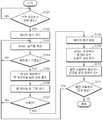
7 is a flowchart showing a control method of the vehicle driving system according to the embodiment of FIG.
8 is a block diagram showing a vehicle driving system according to another embodiment of the present invention.
Fig. 9 is a flowchart showing a control method of the vehicle driving system according to the embodiment of Fig. 8 of the present invention.
본 발명은 다양한 변환을 가할 수 있고 여러 가지 실시 예를 가질 수 있는바, 특정 실시 예들을 도면에 예시하고 상세한 설명에 상세하게 설명하고자 한다. 그러나, 이는 본 발명을 특정한 실시 형태에 대해 한정하려는 것이 아니며, 본 발명의 사상 및 기술 범위에 포함되는 모든 변환, 균등물 내지 대체물을 포함하는 것으로 이해되어야 한다. 본 발명을 설명함에 있어서 관련된 공지 기술에 대한 구체적인 설명이 본 발명의 요지를 흐릴 수 있다고 판단되는 경우 그 상세한 설명을 생략한다.BRIEF DESCRIPTION OF THE DRAWINGS The present invention is capable of various modifications and various embodiments, and specific embodiments are illustrated in the drawings and described in detail in the detailed description. It is to be understood, however, that the invention is not to be limited to the specific embodiments, but includes all modifications, equivalents, and alternatives falling within the spirit and scope of the invention. DETAILED DESCRIPTION OF THE PREFERRED EMBODIMENTS Hereinafter, the present invention will be described in detail with reference to the accompanying drawings.
본 출원에서 사용한 용어는 단지 특정한 실시 예를 설명하기 위해 사용된 것으로, 본 발명을 한정하려는 의도가 아니다. 단수의 표현은 문맥상 명백하게 다르게 뜻하지 않는 한, 복수의 표현을 포함한다. 본 출원에서, "포함하다" 또는 "가지다" 등의 용어는 명세서상에 기재된 특징, 숫자, 단계, 동작, 구성요소, 부품 또는 이들을 조합한 것이 존재함을 지정하려는 것이지, 하나 또는 그 이상의 다른 특징들이나 숫자, 단계, 동작, 구성요소, 부품 또는 이들을 조합한 것들의 존재 또는 부가 가능성을 미리 배제하지 않는 것으로 이해되어야 한다.The terminology used in this application is used only to describe a specific embodiment and is not intended to limit the invention. The singular expressions include plural expressions unless the context clearly dictates otherwise. In the present application, the terms "comprises" or "having" and the like are used to specify that there is a feature, a number, a step, an operation, an element, a component or a combination thereof described in the specification, But do not preclude the presence or addition of one or more other features, integers, steps, operations, elements, components, or combinations thereof.
이하, 본 발명에 따른 실시 예들을 첨부도면을 참조하여 상세히 설명하기로 하며, 첨부 도면을 참조하여 설명함에 있어, 동일하거나 대응하는 구성 요소는 동일한 도면번호를 부여하고 이에 대한 중복되는 설명은 생략하기로 한다.DETAILED DESCRIPTION OF THE PREFERRED EMBODIMENTS Hereinafter, exemplary embodiments of the present invention will be described in detail with reference to the accompanying drawings. Referring to the accompanying drawings, the same or corresponding components are denoted by the same reference numerals, .
도 1은 본 발명의 일 실시 예에 따른 차량 운행 시스템(1)을 나타내는 블록도이다. 차량 운행 시스템(1)이 적용되는 운송 수단은 예를 들면 자동차, 전기 자전거 등일 수 있다.1 is a block diagram showing a
도 1을 참조하면, 차량 운행 시스템(1)은 배터리 팩(100), 스타트 모터(110), 발전 모듈(120), 냉각부(130), 전기 부하(140), 메인 제어부(150)를 포함한다.1, a
배터리 팩(100)은 발전 모듈(110)로부터 생성되는 전류를 공급받아 전기 에너지를 저장하고, 스타트 모터(120)로 스타트 모터(120)의 구동 전류를 공급한다. 또한 배터리 팩(100)은 저장된 전력을 후술할 배터리 관리부(102), 팬 제어부(132), 메인 제어부(150) 등의 제어 유닛의 동작 전원으로서 공급할 수 있을 것이다. 배터리 팩(100)은 배터리(101)와 배터리 관리부(BMS: Battery Management System)(102)를 포함한다.The
배터리(101)는 충전 가능한 이차 전지일 수 있으며, 적어도 하나의 배터리 셀이 직렬 및/또는 병렬로 연결되어 구성될 수 있다. 배터리(101)는 바람직하게는 리튬-이온 전지(lithium ion battery)일 수 있다.The
본 실시 예에 따른 배터리 팩(100)은 연비 개선을 위해, ISG(Idle Stop & Go) 기능이 구현된 ISG 시스템의 엔진 시동을 위한 전원공급장치에 적용될 수 있다. ISG 시스템에서는 엔진의 중지와 재시동이 빈번하게 반복됨에 따라 배터리 팩(100)의 충전 및 방전이 반복된다.The
종래 ISG 시스템에 적용되는 납 축전지는, 충전 및 방전 동작이 빈번하게 반복되는 경우 수명이 단축되고, 충방전 특성이 저하되는 문제가 있었다. 예를 들어 충전 및 방전의 반복에 따라 충전 용량이 저하되어 엔진의 시동성이 저하되며, 이로 인하여 납 축전지의 교환 주기가 짧아지는 문제가 있었다.The lead acid battery applied to the conventional ISG system has a problem that when the charging and discharging operations are repeated frequently, the lifespan is shortened and the charging and discharging characteristics are deteriorated. For example, there is a problem in that the charge capacity is lowered due to repetition of charging and discharging and the startability of the engine is lowered, thereby shortening the replacement cycle of the lead-acid battery.
그러나 본 실시 예에 따르면, 배터리 팩(100)이 납 축전지에 비해, 충방전 특성이 비교적 일정하게 유지되며 경시적 열화가 적은 리튬-이온 전지를 포함함으로써, 엔진의 중지 및 재시동이 반복되는 ISG 시스템에 적합하게 적용될 수 있다. 또한 동일 충전 용량의 납 축전지에 비해 무게를 낮출 수 있으므로 연비개선 효과를 기대할 수 있으며, 납 축전지보다 적은 부피로도 동일 충전 용량을 구현할 수 있으므로 탑재 공간을 절약할 수 있다는 장점이 있다.However, according to the present embodiment, since the
본 실시 예에서 배터리(101)는 리튬-이온 전지에 한정되는 것은 아니며 다양한 종류의 전지를 포함할 수 있다. 단, 배터리(101)로서 사용되는 전지는 발전 모듈(120)의 출력 전압보다 정격 전압이 낮을 수 있다. 예를 들면, 배터리(101)로는 니켈-수소 전지(NiMH: nickel metal hybride battery), 니켈-카드뮴 전지(nickel-cadmium battery) 등이 사용될 수 있다.In this embodiment, the
본 실시 예에 따르면 배터리 팩(100)은 배터리 관리부(102)를 포함한다. 리튬-이온 전지 등은 납 축전지에 비하여 충방전 특성이 좋은 대신 안정성이 낮은 문제점이 있다. 따라서 배터리 팩(100)에는 배터리 관리부(102)를 포함시켜 배터리(101)가 안정적으로 충전 또는 방전될 수 있도록 한다. 즉, 배터리 관리부(102)는 배터리(101)의 충전 및 방전을 제어하여 배터리(101)의 과충전이나 과방전을 방지한다. 예를 들어, 배터리 관리부(102)는 배터리(101)의 만충전시에는 배터리(101)로 공급되는 전력을 차단한다.According to the present embodiment, the
배터리 관리부(102)는 제3 단자(P3)를 통하여 메인 제어부(150)와 통신하여 배터리(101)의 충전 상태나 온도 등 각종 데이터를 주고받을 수 있다. 또한 배터리 관리부(102)는 제4 단자(P4)를 통하여 후술할 팬 제어부(132)로 배터리의 충전 상태에 대한 데이터를 전송할 수 있다. 배터리 관리부(102)의 구체적인 구성에 대하여는 도 2를 참조하여 자세히 설명하도록 한다.The
스타트 모터(110)는 차량의 시동시에 가동되며, 엔진(미도시)의 구동축을 회전시키는 초기 회전 동력을 제공한다. 예를 들어, 스타트 모터(110)는 배터리 팩(100)의 제1 단자(P1) 및 제2 단자(P2)를 통하여 전력을 공급받아 엔진의 시동시 또는 아이들 스탑(idle stop) 이후 엔진의 재시동시에 구동축을 회전시켜 엔진을 가동할 수 있다.The
발전 모듈(120)은 엔진의 구동축과 연결되어 엔진의 가동 중에 구동되어 회전 동력을 전기적인 출력으로 변환한다. 즉, 발전 모듈(120)은 엔진의 가동 중에 전력을 생성하는 구성으로서, 예를 들어 얼터네이터(alternator) 등일 수 있다. 발전 모듈(120)은 DC 발전기 또는 AC 발전기와 정류장치 등을 포함할 수 있으며, 대략 DC 15V, 보다 구체적으로 DC 14.4~14.8의 전압을 갖는 전력을 생성하여 적절한 부분에 공급할 수 있다. 여기서 발전 모듈(120)이 생성한 전력을 공급하는 적절한 부분이란 배터리 팩(100), 냉각부(130), 전기 부하(140) 등일 수 있다.The
냉각부(130)는 배터리 팩(100)의 충전 및 방전에 따른 온도 상승을 감지하여 배터리 팩(100)을 냉각시켜 배터리 팩(100)의 온도를 낮춰준다. 냉각부(130)는 전원을 공급받아 회전 동력으로부터 바람을 생성하는 팬(131)과 팬(131)의 구동을 제어하는 팬 제어부(132)를 포함할 수 있다. 또한 냉각부(130)는 팬(131)으로 흐르는 전류의 흐름을 제어하는 스위칭부(133)를 포함할 수 있다.The
팬(131)은 배터리 팩(100)을 직접 냉각시킬 수 있도록 가능한 팬(131)에서 발생한 바람이 배터리 팩(100) 또는 배터리 팩(100)에 포함된 배터리(101)에 직접 도달하도록 구성할 수 있다. 또는 팬(131)은 적어도 덕트 등을 통하여 바람이 배터리 팩(100)이나 배터리(101)로 도달하도록 구성할 수도 있을 것이다.The
본 실시 예에 따른 팬 제어부(132)는 배터리 관리부(102)로부터 배터리(101)의 충전 상태에 대한 데이터를 수신한다. 팬 제어부(132)는 수신한 데이터에 기초하여 팬(131)을 구동한다. 예를 들어, 팬 제어부(132)의 동작은 다음과 같다.The
팬 제어부(132)는 배터리(101)의 충전 상태가 기준치 예컨데 90% 이하인 경우에는 스위칭부(133)를 OFF 시켜 팬(131)으로 공급되는 전력을 차단할 수 있다. 또한 팬 제어부(132)는 배터리(101)의 충전 상태가 기준치보다 클 경우에는 스위칭부(133)를 ON 시켜 팬(131)으로 전력을 공급하며, 팬(131)을 구동시키되 배터리(101)의 충전 상태에 기초하여 팬(131)의 회전 속도를 조절할 수 있다. 또한 팬 제어부(132)는 배터리(101)가 만충전 상태인 경우에는 스위칭부(133)를 ON 시키고 발전 모듈(120)에서 생성되는 모든 전력이 팬(131)에서 소비되도록 팬(131)의 회전 속도를 제어할 수 있다.The
전기 부하(140)는 배터리 팩(100)에 저장된 전력을 소비하는 구성이다. 전기 부하(140)는 예를 들면 네비게이션, 오디오, 조명등, 차량용 블랙 박스, 도단 방지 장치 등 다양한 종류의 전자 장치일 수 있다. 전기 부하(140)를 이루는 구성의 개수 및 종류는 운송 수단의 구체적인 구현 예에 따라 달라질 수 있다.The
메인 제어부(150)는 배터리 팩(100)이 장착된 차량 운행 시스템(1)의 전체 동작을 제어하는 제어부이다. 메인 제어부(150)는 배터리 팩(100)과 제3 단자(P3)를 통해 연결되어 각종 데이터 및 제어 신호를 교환하고, 배터리 팩(100)의 상태를 모니터링 하고, 배터리 팩(100)의 동작을 제어할 수 있다.The
도 2는 도 1에 따른 배터리 팩(100)의 구조를 나타내는 블록도이다.2 is a block diagram showing the structure of the
배터리 팩(100)은 앞서 설명한 바와 같이 배터리(101), 배터리 관리부(102), 제1 내지 제4 단자(P1~P4)를 포함하며, 배터리 관리부(102)는 다시 배터리 제어부(103)와 보호회로(104)를 포함할 수 있다.The
배터리 제어부(103)는 배터리(101)의 상태를 모니터링하고, 모니터링 결과를 메인 제어부(150)로 전송한다. 즉, 배터리 제어부(103)는 배터리(101)에 걸리는 전압, 배터리(101)에 흐르는 전류, 배터리(101)의 온도, 배터리(101)의 충전 상태 등의 데이터를 검출한다. 배터리 제어부(103)는 상기 각각의 데이터를 독립적으로 검출할 수도 있으며, 어느 하나의 데이터로부터 추정하여 획득할 수도 있다. 예를 들어, 배터리 제어부(103)는 배터리(101)의 전압을 측정하고, 측정한 전압으로부터 배터리(101)의 충전 상태 또는 온도 등을 추정할 수 있다.The
배터리 제어부(103)는 검출한 각종 데이터를 제3 단자(P3)를 통하여 메인 제어부(150)로 전송한다. 그리고 배터리 제어부(103)는 메인 제어부(150)로부터 데이터나 제어신호 등을 수신하고, 수신한 데이터나 제어신호에 따라서 동작할 수 있을 것이다.The
또한 배터리 제어부(103)는 검출한 각종 데이터들 중 배터리(101)의 충전 상태를 나타내는 데이터를 제4 단자(P4)를 통하여 팬 제어부(132)로 전송한다. 이때 배터리(101)의 충전 상태를 나타내는 데이터는 SOC을 추정하는데 사용되는 배터리(101)의 전압 데이터일 수 있다.The
보호회로(104)는 배터리 제어부(103)의 제어에 따라서 배터리(101)로의 전류의 흐름을 제어한다. 예를 들어, 배터리(101)에 과전류가 흐르는 경우, 또는 배터리(101)가 과충전된 경우, 배터리 제어부(103)는 보호회로(104)가 전류 경로를 차단하도록 제어하며, 상기 제어에 따라서 보호회로(104)는 내부에 구비된 스위칭 소자 등을 Off 시켜 전류의 흐름을 차단한다.The
도 3는 본 발명의 일 실시 예에 따른 발전 모듈(120)의 전류 생성량을 나타내는 그래프이다. 가로축은 시간을 나타내며 세로축은 전류의 크기를 나타낸다.3 is a graph showing current generation amount of the
도 3을 참조하면, 발전 모듈(120)에서 전력을 생성하면 전류가 배터리 팩(100)으로 유입된다. 전류가 유입된 양이 증가할수록 배터리(101)의 충전량이 증가하며, t1에서 배터리(101)는 만충전 상태가 된다. 그러나 발전 모듈(120)에서는 계속해서 전력이 생성되어 전류가 유입되며(t1 이후의 빗금친 부분), 따라서 t1 이후의 전력이 배터리(101)로 계속해서 공급되면 배터리(101)가 과충전 상태가 되어 열화가 발생하는 등 배터리(101)에 손상이 발생한다.Referring to FIG. 3, when power is generated in the
도 4 내지 도 6은 도 1의 실시 예에 따른 차량 운행 시스템(1)의 동작 상태를 나타내는 도면이다. 도 4는 배터리(101)가 아직 충분히 충전되지 않은 경우를 나타낸다.4 to 6 are diagrams showing the operating states of the
도 4를 참조하면, 발전 모듈(120)에서 전력을 생성하고, 이에 따라서 전류 I1이 생성된다. 생성된 전류 I1은 배터리 팩(100) 및 냉각부(130) 측으로 흐른다.Referring to FIG. 4, a
배터리 제어부(103)는 배터리(101)의 충전 상태를 검출하고, 배터리(101)의 충전이 필요하다고 판단하여 보호회로(104)에 포함된 스위칭 소자를 ON 시키기 위한 제어신호 Son을 생성하여 스위칭 소자에 인가한다. 이로 인하여 스위칭 소자가 ON 상태가 되어 전류 I2가 배터리(101)로 유입되어 충전이 진행된다. 예를 들어, 배터리(101)의 충전 상태가 90% 이하일 경우, 배터리 제어부(103)는 스위칭 소자를 ON 시키고 배터리(101)를 충전한다.The
배터리 제어부(103)는 또한 배터리(101)의 충전 상태에 대한 데이터, 즉 배터리(101)의 전압에 관한 데이터 Sv를 팬 제어부(132)로 직접 전송한다. 팬 제어부(132)는 수신한 데이터 Sv에 기초하여 배터리(101)의 냉각이 필요 없다고 판단한다. 따라서 팬 제어부(132)는 스위칭부(133)가 OFF 상태가 되도록 제어신호 Soff를 스위칭부(133)로 인가하여 팬(131)으로 유입되는 전류 I3를 차단한다.The
따라서 I1 = I2 가 되며, I3 = 0 이 된다. 즉, 배터리(101)가 충전되며 냉각부(130)는 구동되지 않는다.Therefore, I1 = I2 and I3 = 0. That is, the
팬 제어부(132)는 배터리 제어부(103)로부터 수신한 배터리(101)의 충전 상태에 대한 데이터, 특히 배터리(101)의 전압에 관한 데이터에 기초하여 배터리(101)의 온도를 추정할 수 있다. 배터리(101)의 전압이 높을수록 배터리(101)의 충전이 오래 진행된 것이며, 따라서 배터리(101)의 온도가 높을 것이라고 추정할 수 있다. 따라서 팬 제어부(132)는 배터리 제어부(103)로부터 수신한 배터리(101)의 전압에 관한 데이터가 기준치 이하이면 배터리(101)의 냉각이 필요 없다고 판단하며, 따라서 팬(131)을 구동시키지 않을 수 있다.The
도 5는 배터리(101)의 충전량이 기준값보다 클 경우를 나타낸다.5 shows a case where the charged amount of the
도 5를 참조하면, 발전 모듈(120)에서 전력을 생성하고, 이에 따라서 전류 I1이 생성된다. 생성된 전류 I1은 배터리 팩(100) 및 냉각부(130) 측으로 흐른다.Referring to FIG. 5,
배터리 제어부(103)는 배터리(101)의 충전 상태를 검출하고, 배터리(101)의 충전량이 기준값보다 크다고 판단하여 보호회로(104)에 포함된 스위칭 소자를 계속해서 ON 시키고, 배터리(101)를 충전한다.The
배터리 제어부(103)는 배터리(101)의 충전 상태에 대한 데이터, 즉 배터리(101)의 전압에 관한 데이터 Sv를 팬 제어부(132)로 직접 전송한다. 팬 제어부(132)는 수신한 데이터 Sv에 기초하여 배터리(101)의 냉각이 필요하다고 판단한다. 따라서 팬 제어부(132)는 스위칭부(133)가 ON 상태가 되도록 하는 제어신호 Son을 스위칭부(133)로 인가하여 팬(131)으로 전류 I3를 유입시켜 팬(131)의 구동을 개시한다.The
따라서 I1 = I2 + I3가 되며, I2 ≠ 0, I3 ≠ 0 이 된다. 즉, 배터리(101)의 충전과 냉각부(130)의 구동이 동시에 수행된다.Therefore, I1 = I2 + I3, I2 ≠ 0, and I3 ≠ 0. That is, the charging of the
팬 제어부(132)는 배터리 제어부(103)로부터 수신한 배터리(101)의 전압에 관한 데이터에 기초하여 배터리(101)의 온도를 추정할 수 있다. 배터리(101)의 충전량이 기준값보다 크므로 배터리(101)의 전압도 기준전압보다 커지며, 따라서 배터리(101)의 온도가 높을 것이라고 추정할 수 있다. 따라서 팬 제어부(132)는 배터리 제어부(103)로부터 수신한 배터리(101)의 전압에 관한 데이터가 기준치보다 크면 배터리(101)의 냉각이 필요하다고 판단하며, 따라서 팬(131)을 구동시킨다.The
이때, 팬 제어부(132)는 배터리(101)의 온도에 따라서 냉각의 정도를 결정하여야 한다. 따라서 팬 제어부(132)는 배터리(101)의 전압에 관한 데이터에 기초하여 팬(131)의 회전 속도를 결정하여 제어신호 Sd를 생성하고 생성된 제어신호 Sd를 팬(131)에 인가하여 팬(131)을 구동할 수 있을 것이다. 즉, 팬(131)으로 유입되는 전류의 양을 조절할 수 있을 것이다. 이로 인하여 발전 모듈(120)에서 생성되는 전력 중 배터리 팩(100)의 충전에 사용되는 전력량과 냉각부(130)에서 사용되는 전력량을 결정할 수 있게 된다.At this time, the
도 6은 배터리(101)가 만충전된 경우를 나타낸다.6 shows a case where the
도 6을 참조하면, 발전 모듈(120)에서 전력을 생성하고, 이에 따라서 전류 I1이 생성된다. 생성된 전류 I1은 배터리 팩(100) 및 냉각부(130) 측으로 흐른다.Referring to FIG. 6,
배터리 제어부(103)는 배터리(101)의 충전 상태를 검출하고, 배터리(101)가 만충전 되었다고 판단하여 보호회로(104)에 포함된 스위칭 소자를 OFF 시키기 위한 제어신호 Soff를 생성하여 스위칭 소자에 인가한다. 이루 인하여 스위칭 소자가 OFF 상태가 되어 배터리(101)로 유입되는 전류가 차단되어 충전이 종료된다.The
배터리 제어부(103)는 배터리(101)의 충전 상태에 대한 데이터, 즉 배터리(101)의 전압에 관한 데이터를 팬 제어부(132)로 직접 전송한다. 팬 제어부(132)는 수신한 데이터에 기초하여 배터리(101)의 냉각이 필요하다고 판단한다. 따라서 팬 제어부(132)는 스위칭부(133)가 계속해서 ON 상태가 되도록 하여 팬(131)으로 전류 I3를 유입시켜 팬(131)을 계속해서 회전시킨다.The
따라서 I1 = I3 가 되며, I2 = 0 이 된다. 즉, 배터리(101)의 충전은 종료되고 냉각부(130)만 구동된다.Therefore, I1 = I3 and I2 = 0. That is, the charging of the
팬 제어부(132)는 배터리 제어부(103)로부터 수신한 배터리(101)의 전압에 관한 데이터에 기초하여 배터리(101)의 온도를 추정할 수 있다. 배터리(101)가 만충전된 상태이므로 크므로 배터리(101)의 전압도 기준전압보다 커지며, 따라서 배터리(101)의 온도가 높을 것이라고 추정할 수 있다. 따라서 팬 제어부(132)는 배터리 제어부(103)로부터 수신한 배터리(101)의 전압에 관한 데이터가 기준치보다 크면 배터리(101)의 냉각이 필요하다고 판단하며, 따라서 팬(131)을 구동시킨다.The
이때, 배터리(101)는 만충전 상태라서 온도가 최대가 되어있으므로 냉각부(130)를 최대로 가동시킬 필요가 있다. 또한 배터리(101)로 전력이 공급되어 배터리(101)가 충전되면 배터리(101)가 열화될 수도 있다. 따라서 팬 제어부(132)는 발전 모듈(120)에서 생성된 전력을 모두 소비하도록 팬(131)을 회전시킨다.At this time, since the
본 실시 예에서는 배터리 제어부(103)에서 팬 제어부(132)로 배터리(101)의 전압에 관한 데이터를 전송하고, 팬 제어부(132)가 수신한 데이터에 기초하여 배터리(101)의 온도를 판단하여 팬(131)의 구동 여부, 및 회전 속도를 제어하도록 하였으나 이에 한정되는 것은 아니다. 예를 들어, 배터리 제어부(103)에서 배터리(101)의 전압에 기초하여 배터리(101)의 온도를 판단하고, 배터리 제어부(103)는 판단 결과에 기초하여 냉각부(130)를 제어하기 위한 제어신호를 팬 제어부(132)에 인가하도록 구성할 수도 있을 것이다.The
도 7은 도 1의 실시 예에 따른 차량 운행 시스템(1)의 제어방법을 나타내는 흐름도이다.FIG. 7 is a flowchart showing a control method of the
도 7을 참조하면, 메인 제어부(150) 또는 배터리 관리부(102)는 발전 모듈(120)에서 전력이 생성되는지를 판단한다(S101). 발전 모듈(120)에서 전력이 생성될 경우 배터리(101)의 충전을 개시한다(S102).Referring to FIG. 7, the
배터리 제어부(103)는 배터리(101)의 충전 상태를 검출하고 이에 기초하여 충전량을 측정한다(S103). 측정한 충전량이 기준값보다 큰지를 판단하고(S104), 측정한 충전량이 기준값 이하라고 판단한 경우에는 S103 단계로 돌아간다.The
측정한 충전량이 기준값보다 큰 경우에는 배터리 제어부(103)는 팬 제어부(132)로 충전 상태를 통지한다(S105). 즉 배터리 제어부(103)는 배터리(101)의 충전 상태에 대한 데이터, 예를 들어 배터리(101)의 전압에 관한 데이터를 팬 제어부(132)로 전송한다.When the measured charge amount is larger than the reference value, the
그리고 팬 제어부(132)는 수신한 배터리(101)의 전압에 관한 데이터에 기초하여 배터리(101)의 온도가 높다고 추정하고, 이로부터 팬(131)의 구동이 필요하다고 판단하여 팬(131)의 구동을 개시한다(S106).The
배터리 제어부(103)는 배터리(101)가 만충전 되었는지를 판단하고(S107), 만충전이 되지 않은 경우 S103 단계로 돌아가 앞서 설명한 단계를 반복한다. 반면에 배터리(101)가 만충전 되었다고 판단한 경우에는 보호회로(104)에 포함된 스위칭 소자를 OFF시켜 배터리(101)의 충전을 종료한다(S108).The
배터리 제어부(103)는 팬 제어부(132)로 배터리(101)의 만충전 상태를 통지한다(S109). 즉, 배터리(101)의 전압에 관한 데이터를 팬 제어부(132)로 전송한다.The
팬 제어부(132)는 수신한 데이터에 기초하여 배터리(101)가 만충전 되었으며 온도가 충분히 높은 상태일 것이라고 추정한다. 따라서 팬 제어부(132)는 발전 모듈(120)에서 생성되는 전력을 모두 소비하도록 팬(131)의 회전 속도를 증가시킨다(S110).The
그리고 발전 모듈(120)에서 전력이 계속해서 생성되는지를 판단하여(S111) 전력이 생성되는 경우에는 S103 단계로 돌아가며, 전력이 생성되지 않는 경우에는 동작을 종료한다.Then, it is determined whether power is continuously generated in the power generation module 120 (S111). If power is generated, the process returns to S103. If power is not generated, the operation is terminated.
상기와 같이, 본 실시 예에 따른 차량 운행 시스템(1)에 따르면 배터리(101)가 만충전 되면 더 이상의 충전이 수행되지 않도록 배터리(101)로 공급되는 전력을 차단하고, 발전 모듈(120)에서 생성되는 전력이 모두 팬(131)에 의하여 소비되도록 제어한다. 따라서 배터리(101)의 열화 등 성능 저하를 방지할 수 있을 뿐만 아니라 배터리(101)를 냉각시킴으로 인하여 배터리 팩(100)의 안정성을 향상시킬 수 있게 된다.As described above, according to the
또한 팬 제어부(132)는 배터리(101)의 전압에 기초하여 배터리(101)의 온도를 추정하고, 이로부터 팬(131)의 구동 여부 및 회전 속도를 조절할 수 있으며, 따라서 별도로 배터리(101)의 온도를 측정할 필요가 없게 되어 배터리(101)의 온도 측정을 위한 구성을 생략할 수 있게 된다.The
도 8은 본 발명의 다른 실시 예에 따른 차량 운행 시스템(1)을 나타내는 블록도이다. 본 실시 예에서는 도 1에 따른 차량 운행 시스템(2)과의 차이점을 중점적으로 설명하도록 한다.8 is a block diagram showing a
도 8을 참조하면, 본 실시 예에 따른 배터리 관리부(202)는 배터리(201)의 충전 상태에 대한 데이터, 즉 배터리(201)의 전압에 관한 데이터를 메인 제어부(250)로 전송한다.Referring to FIG. 8, the
메인 제어부(250)는 수신한 데이터에 기초하여 팬(231)의 구동 여부를 지시하는 제어신호를 팬 제어부(232)로 전송한다. 즉 메인 제어부(250)가 팬 제어부(232)의 동작을 지시한다.The
팬 제어부(232)는 메인 제어부(250)로부터의 지시에 기초하여 팬(231)을 구동한다. 메인 제어부(250)로부터의 지시에 팬(231)의 구동 여부 및 회전 속도가 모두 포함되어 있을 수 있다. 또는 메인 제어부(250)는 배터리 관리부(202)로부터 수신한 배터리(201)의 전압에 관한 데이터 또는 그에 기초한 온도 데이터를 수신하고, 팬 제어부(232)가 수신한 데이터에 기초하여 팬(231)의 구동 여부 및 회전 속도를 결정할 수도 있을 것이다.The
이상과 같이 본 실시 예는 배터리(201)의 전압에 관한 데이터 및 그에 기초한 배터리(101)의 온도 추정에 배터리 관리부(202)와 팬 제어부(232) 뿐만 아니라 메인 제어부(250)가 관여하게 된다.The
도 9는 본 발명의 도 8의 실시 예에 따른 차량 운행 시스템의 제어방법을 나타내는 흐름도이다.Fig. 9 is a flowchart showing a control method of the vehicle driving system according to the embodiment of Fig. 8 of the present invention.
도 9를 참조하면, 메인 제어부(250) 또는 배터리 관리부(202)는 발전 모듈(220)에서 전력이 생성되는지를 판단한다(S201). 발전 모듈(220)에서 전력이 생성될 경우 배터리(201)의 충전을 개시한다(S202).Referring to FIG. 9, the
배터리 관리부(202)는 배터리(201)의 충전 상태를 검출하고 이에 기초하여 충전량을 측정한다(S203). 측정한 충전량이 기준값보다 큰지를 판단하고(S204), 측정한 충전량이 기준값 이하라고 판단한 경우에는 S203 단계로 돌아간다.The
측정한 충전량이 기준값보다 큰 경우에는 배터리 관리부(202)는 메인 제어부(250)로 충전 상태를 통지한다(S205). 즉 배터리 관리부(202)는 배터리(201)의 충전 상태에 대한 데이터, 예를 들어 배터리(201)의 전압에 관한 데이터를 메인 제어부(250)로 전송한다. 메인 제어부(250)는 수신한 데이터에 기초하여 팬(231)의 구동 여부를 지시하는 제어신호를 팬 제어부(232)로 전송한다. 즉 메인 제어부(250)가 팬 제어부(232)의 동작을 지시한다(S206).If the measured charge amount is larger than the reference value, the
그리고 팬 제어부(232)는 수신한 지시에 기초하여 배터리(201)의 온도가 높다고 추정하고, 이로부터 팬(231)의 구동이 필요하다고 판단하여 팬(231)의 구동을 개시한다(S207).Then, the
배터리 관리부(202)는 배터리(201)가 만충전 되었는지를 판단하고(S208), 만충전이 되지 않은 경우 S203 단계로 돌아가 앞서 설명한 단계를 반복한다. 반면에 배터리(201)가 만충전 되었다고 판단한 경우에는 보호회로에 포함된 스위칭 소자를 OFF시켜 배터리(201)의 충전을 종료한다(S209).The
배터리 관리부(202)는 메인 제어부(250)로 배터리(201)의 만충전 상태를 통지한다(S210). 즉, 배터리(201)의 전압에 관한 데이터를 메인 제어부(250)로 전송한다. 그리고 메인 제어부(250)가 수신한 데이터에 기초하여 다시 팬 제어부(232)의 동작을 지시한다(S211).The
팬 제어부(232)는 수신한 지시에 기초하여 배터리(201)가 만충전 되었으며 온도가 충분히 높은 상태일 것이라고 추정한다. 따라서 팬 제어부(232)는 발전 모듈(220)에서 생성되는 전력을 모두 소비하도록 팬(231)의 회전 속도를 증가시킨다(S212).The
그리고 발전 모듈(220)에서 전력이 계속해서 생성되는지를 판단하여(S213) 전력이 생성되는 경우에는 S203 단계로 돌아가며, 전력이 생성되지 않는 경우에는 동작을 종료한다.The
상기와 같이, 본 실시 예에 따른 차량 운행 시스템(2)에 따르면 배터리(201)가 만충전 되면 더 이상의 충전이 수행되지 않도록 배터리(201)로 공급되는 전력을 차단하고, 발전 모듈(220)에서 생성되는 전력이 모두 팬(231)에 의하여 소비되도록 제어한다. 따라서 배터리(201)의 열화 등 성능 저하를 방지할 수 있을 뿐만 아니라 배터리(201)를 냉각시킴으로 인하여 배터리 팩(200)의 안정성을 향상시킬 수 있게 된다.As described above, according to the
또한 팬 제어부(232)는 배터리(201)의 전압에 기초하여 배터리(201)의 온도를 추정하고, 이로부터 팬(231)의 구동 여부 및 회전 속도를 조절할 수 있으며, 따라서 별도로 배터리(201)의 온도를 측정할 필요가 없게 되어 배터리(201)의 온도 측정을 위한 구성을 생략할 수 있게 된다.The
본 발명에서 설명하는 특정 실행들은 일 실시 예들로서, 어떠한 방법으로도 본 발명의 범위를 한정하는 것은 아니다. 명세서의 간결함을 위하여, 종래 전자적인 구성들, 제어 시스템들, 소프트웨어, 상기 시스템들의 다른 기능적인 측면들의 기재는 생략될 수 있다. 또한, 도면에 도시된 구성 요소들 간의 선들의 연결 또는 연결 부재들은 기능적인 연결 및/또는 물리적 또는 회로적 연결들을 예시적으로 나타낸 것으로서, 실제 장치에서는 대체 가능하거나 추가의 다양한 기능적인 연결, 물리적인 연결, 또는 회로 연결들로서 나타내어질 수 있다. 또한, “필수적인”, “중요하게” 등과 같이 구체적인 언급이 없다면 본 발명의 적용을 위하여 반드시 필요한 구성 요소가 아닐 수 있다.The specific acts described in the present invention are, by way of example, not intended to limit the scope of the invention in any way. For brevity of description, descriptions of conventional electronic configurations, control systems, software, and other functional aspects of such systems may be omitted. Also, the connections or connecting members of the lines between the components shown in the figures are illustrative of functional connections and / or physical or circuit connections, which may be replaced or additionally provided by a variety of functional connections, physical Connection, or circuit connections. Also, unless explicitly mentioned, such as " essential ", " importantly ", etc., it may not be a necessary component for application of the present invention.
본 발명의 명세서(특히 특허청구범위에서)에서 “상기”의 용어 및 이와 유사한 지시 용어의 사용은 단수 및 복수 모두에 해당하는 것일 수 있다. 또한, 본 발명에서 범위(range)를 기재한 경우 상기 범위에 속하는 개별적인 값을 적용한 발명을 포함하는 것으로서(이에 반하는 기재가 없다면), 발명의 상세한 설명에 상기 범위를 구성하는 각 개별적인 값을 기재한 것과 같다. 마지막으로, 본 발명에 따른 방법을 구성하는 단계들에 대하여 명백하게 순서를 기재하거나 반하는 기재가 없다면, 상기 단계들은 적당한 순서로 행해질 수 있다. 반드시 상기 단계들의 기재 순서에 따라 본 발명이 한정되는 것은 아니다. 본 발명에서 모든 예들 또는 예시적인 용어(예들 들어, 등등)의 사용은 단순히 본 발명을 상세히 설명하기 위한 것으로서 특허청구범위에 의해 한정되지 않는 이상 상기 예들 또는 예시적인 용어로 인해 본 발명의 범위가 한정되는 것은 아니다. 또한, 당업자는 다양한 수정, 조합 및 변경이 부가된 특허청구범위 또는 그 균등물의 범주 내에서 설계 조건 및 팩터에 따라 구성될 수 있음을 알 수 있다.The use of the terms " above " and similar indication words in the specification of the present invention (particularly in the claims) may refer to both singular and plural. In addition, in the present invention, when a range is described, it includes the invention to which the individual values belonging to the above range are applied (unless there is contradiction thereto), and each individual value constituting the above range is described in the detailed description of the invention The same. Finally, the steps may be performed in any suitable order, unless explicitly stated or contrary to the description of the steps constituting the method according to the invention. The present invention is not necessarily limited to the order of description of the above steps. The use of all examples or exemplary language (e.g., etc.) in this invention is for the purpose of describing the present invention only in detail and is not to be limited by the scope of the claims, It is not. It will also be appreciated by those skilled in the art that various modifications, combinations, and alterations may be made depending on design criteria and factors within the scope of the appended claims or equivalents thereof.
1,2차량 운행 시스템100,200배터리 팩
101,201배터리102,202배터리 관리부
103배터리 제어부104보호회로
110,210스타트 모터120,220발전 모듈
130,230냉각부131,231팬
132,232팬 제어부133,233스위칭부
140,240전기 부하150,250메인 제어부1,2 Vehicle operation system 100,200 battery pack
101, 201
103
110,210 Start motor 120,220 Power generation module
130, 230
132, 232,
140,240 Electrical load 150,250 Main control unit
Claims (20)
Translated fromKorean상기 발전 모듈에서 생성된 전력을 사용하여 충전되는 배터리;
상기 배터리의 충전을 제어하는 배터리 관리부;
상기 배터리를 냉각하는 냉각부; 및
상기 배터리 관리부로부터 상기 배터리의 충전 상태에 관한 데이터인 상기 배터리의 전압을 수신하여 상기 배터리의 온도를 추정하고, 상기 추정된 온도에 따라 상기 냉각부를 제어하는 메인 제어부;를 포함하며,
상기 배터리 관리부는 상기 배터리의 만충전시 상기 배터리로 공급되는 전력을 차단하며,
상기 냉각부는 상기 배터리 관리부가 상기 배터리로 공급되는 전력을 차단할 경우, 상기 발전 모듈에서 생성되는 전력을 모두 소비하는 것을 특징으로 하는, 차량 운행 시스템.A power generation module for generating power;
A battery that is charged using power generated by the power generation module;
A battery management unit for controlling charging of the battery;
A cooling unit for cooling the battery; And
And a main controller for receiving the voltage of the battery, which is data relating to the state of charge of the battery, from the battery management unit, estimating the temperature of the battery, and controlling the cooling unit according to the estimated temperature,
Wherein the battery management unit cuts off the power supplied to the battery to fully charge the battery,
Wherein the cooling unit consumes all the power generated by the power generation module when the battery management unit cuts off power supplied to the battery.
상기 메인 제어부는 상기 배터리 관리부로부터 만충전 상태를 나타내는 데이터를 수신하고, 상기 데이터에 기초하여 상기 냉각부를 제어하는 제어신호를 생성하는 것을 특징으로 하는, 차량 운행 시스템.The method according to claim 1,
Wherein the main control unit receives data indicating a full charge state from the battery management unit and generates a control signal for controlling the cooling unit based on the data.
상기 냉각부는 상기 배터리를 냉각시키기 위한 팬 및 상기 팬의 구동을 제어하는 팬 제어부를 포함하고,
상기 팬 제어부는 상기 제어신호에 따라서 상기 팬의 회전 속도를 조절하는 것을 특징으로 하는, 차량 운행 시스템.The method of claim 3,
Wherein the cooling unit includes a fan for cooling the battery and a fan control unit for controlling driving of the fan,
And the fan control unit adjusts the rotation speed of the fan in accordance with the control signal.
상기 팬 제어부는 상기 발전 모듈에서 생성되는 전력을 모두 소비하도록 상기 팬을 회전시키는 것을 특징으로 하는, 차량 운행 시스템.5. The method of claim 4,
Wherein the fan control unit rotates the fan to consume all the power generated in the power generation module.
상기 메인 제어부는 상기 배터리 관리부로부터 상기 배터리의 충전 상태를 나타내는 데이터를 수신하고, 상기 충전 상태가 기준값보다 클 경우, 상기 냉각부의 구동을 개시하는 제어신호를 생성하는 것을 특징으로 하는, 차량 운행 시스템.The method according to claim 1,
Wherein the main control unit receives data indicating a state of charge of the battery from the battery management unit and generates a control signal for starting driving of the cooling unit when the state of charge is greater than a reference value.
상기 냉각부는 상기 배터리를 냉각시키기 위한 팬 및 상기 팬의 구동을 제어하는 팬 제어부를 포함하고,
상기 팬 제어부는 상기 제어신호에 기초하여 상기 팬의 회전 속도를 조절하는 것을 특징으로 하는, 차량 운행 시스템.The method according to claim 6,
Wherein the cooling unit includes a fan for cooling the battery and a fan control unit for controlling driving of the fan,
And the fan control unit adjusts the rotation speed of the fan based on the control signal.
상기 발전 모듈에서 생성되는 전력을 사용하여 상기 배터리 충전 및 상기 냉각부의 구동을 동시에 수행하는 것을 특징으로 하는, 차량 운행 시스템.The method according to claim 6,
And the battery charging and the cooling unit are simultaneously operated by using the power generated by the power generation module.
상기 발전 모듈에서 생성된 전력을 사용하여 충전되는 배터리;
상기 배터리의 충전을 제어하는 배터리 관리부;
상기 배터리를 냉각하는 냉각부;를 포함하며,
상기 배터리 관리부는 상기 배터리의 만충전시 상기 배터리로 공급되는 전력을 차단하며, 상기 배터리의 충전 상태에 관한 데이터인 상기 배터리의 전압을 상기 냉각부로 직접 전송하고,
상기 냉각부는 상기 배터리의 전압을 나타내는 데이터로부터 상기 배터리의 온도를 추정하고, 상기 추정된 온도에 따라서 제어되며, 상기 배터리 관리부가 상기 배터리로 공급되는 전력을 차단할 경우, 상기 발전 모듈에서 생성되는 전력을 모두 소비하는 것을 특징으로 하는, 차량 운행 시스템.A power generation module for generating power;
A battery that is charged using power generated by the power generation module;
A battery management unit for controlling charging of the battery;
And a cooling unit for cooling the battery,
Wherein the battery management unit cuts off the power supplied to the battery to fully charge the battery and directly transmits the voltage of the battery to the cooling unit,
Wherein the cooling unit estimates the temperature of the battery from the data indicating the voltage of the battery and is controlled according to the estimated temperature and when the battery management unit cuts off power supplied to the battery, Wherein the control unit consumes all of the power consumption of the vehicle.
상기 냉각부는 상기 배터리를 냉각시키기 위한 팬 및 상기 팬의 구동을 제어하는 팬 제어부를 포함하고,
상기 팬 제어부는 상기 데이터에 기초하여 상기 팬의 회전 속도를 조절하는 것을 특징으로 하는, 차량 운행 시스템.12. The method of claim 11,
Wherein the cooling unit includes a fan for cooling the battery and a fan control unit for controlling driving of the fan,
And the fan control unit adjusts the rotation speed of the fan based on the data.
상기 팬 제어부는 상기 배터리 관리부로부터 만충전 상태를 나타내는 데이터를 수신한 경우 상기 발전 모듈에서 생성된 전력을 모두 소비하도록 상기 팬을 회전시키는 것을 특징으로 하는, 차량 운행 시스템.13. The method of claim 12,
Wherein the fan control unit rotates the fan so as to consume all of the power generated by the power generation module when the data indicating the full charge state is received from the battery management unit.
상기 충전 상태가 기준값 이상일 경우, 상기 냉각부의 구동을 개시하는 것을 특징으로 하는, 차량 운행 시스템.12. The method of claim 11,
And starts driving the cooling section when the charging state is equal to or greater than the reference value.
상기 발전 모듈에서 생성되는 전력을 사용하여 상기 배터리 충전 및 상기 냉각부의 구동을 동시에 수행하는 것을 특징으로 하는, 차량 운행 시스템.15. The method of claim 14,
And the battery charging and the cooling unit are simultaneously operated by using the power generated by the power generation module.
상기 배터리의 충전 상태를 판단하는 단계;
상기 배터리의 충전 상태를 나타내는 상기 배터리의 전압에 기초하여 상기 배터리의 온도를 추정하는 단계;
상기 추정된 온도에 따라 상기 발전 모듈에서 생성되는 전력 중 상기 배터리의 충전에 사용되는 전력량과 상기 배터리를 냉각시키는 냉각부에서 사용되는 전력량을 결정하여, 상기 냉각부를 동작시키는 단계;
상기 배터리가 만충전 상태인지 판단하는 단계;
상기 배터리가 만충전 상태일 때 상기 배터리로 공급되는 전력을 차단하는 단계; 및
상기 발전 모듈에서 생성되는 전력을 모두 상기 냉각부에서 소비하는 단계;를 포함하는 것을 특징으로 하는, 차량 운행 제어방법.Charging the battery with power generated in the power generation module;
Determining a state of charge of the battery;
Estimating a temperature of the battery based on a voltage of the battery indicating a state of charge of the battery;
Determining the amount of power used for charging the battery and the amount of power used in the cooling unit for cooling the battery among the power generated by the power generation module according to the estimated temperature, and operating the cooling unit;
Determining whether the battery is fully charged;
Blocking power supplied to the battery when the battery is fully charged; And
And consuming power generated by the power generation module in the cooling unit.
Priority Applications (4)
| Application Number | Priority Date | Filing Date | Title |
|---|---|---|---|
| KR1020120030235AKR101420340B1 (en) | 2012-03-23 | 2012-03-23 | Vehicle operating system and method for controlling the same |
| US13/612,926US9150106B2 (en) | 2012-03-23 | 2012-09-13 | Vehicle operating system and method of controlling the same |
| JP2012232095AJP2013201880A (en) | 2012-03-23 | 2012-10-19 | Vehicle operation system and control method thereof |
| CN2012105647184ACN103318040A (en) | 2012-03-23 | 2012-12-21 | Vehicle operating system and method of controlling the same |
Applications Claiming Priority (1)
| Application Number | Priority Date | Filing Date | Title |
|---|---|---|---|
| KR1020120030235AKR101420340B1 (en) | 2012-03-23 | 2012-03-23 | Vehicle operating system and method for controlling the same |
Publications (2)
| Publication Number | Publication Date |
|---|---|
| KR20130107995A KR20130107995A (en) | 2013-10-02 |
| KR101420340B1true KR101420340B1 (en) | 2014-07-16 |
Family
ID=49187202
Family Applications (1)
| Application Number | Title | Priority Date | Filing Date |
|---|---|---|---|
| KR1020120030235AExpired - Fee RelatedKR101420340B1 (en) | 2012-03-23 | 2012-03-23 | Vehicle operating system and method for controlling the same |
Country Status (4)
| Country | Link |
|---|---|
| US (1) | US9150106B2 (en) |
| JP (1) | JP2013201880A (en) |
| KR (1) | KR101420340B1 (en) |
| CN (1) | CN103318040A (en) |
Families Citing this family (15)
| Publication number | Priority date | Publication date | Assignee | Title |
|---|---|---|---|---|
| KR101584405B1 (en)* | 2013-10-31 | 2016-01-12 | 주식회사 엘지화학 | Application module having fixed interface |
| GB2541920A (en)* | 2015-09-04 | 2017-03-08 | Jaguar Land Rover Ltd | System and method for cooling an electric vehicle |
| CN205790264U (en)* | 2016-02-18 | 2016-12-07 | 徐州中矿大传动与自动化有限公司 | A kind of intelligent battery group with battery cell equilibrium and heat management function |
| US10752257B2 (en) | 2016-02-19 | 2020-08-25 | A Truly Electric Car Company | Car operating system that controls the car's direction and speed |
| KR101786350B1 (en)* | 2016-05-26 | 2017-11-16 | 현대자동차주식회사 | Charging system for plug-in hybrid vehicle and method of controlling the same |
| CN106058370B (en)* | 2016-08-03 | 2018-11-09 | 江苏大学 | A kind of double water cooling electrokinetic cell systems and its control method based on heat conductive silica gel |
| KR102345506B1 (en) | 2017-01-24 | 2021-12-29 | 삼성에스디아이 주식회사 | Battery pack, control method of charging the same, and vehicle comprisin the same |
| TWM575626U (en) | 2017-06-26 | 2019-03-11 | 美商米沃奇電子工具公司 | battery charger |
| CN109818101B (en)* | 2017-11-20 | 2022-03-29 | 明创能源股份有限公司 | Thermal management system for independent large-electric-energy electric equipment |
| KR102518974B1 (en)* | 2018-08-21 | 2023-04-06 | 두산산업차량 주식회사 | Apparatus and method for controlling vehicles motor based on temperature of battery |
| DE102019108412A1 (en)* | 2019-04-01 | 2020-10-01 | Knorr-Bremse Systeme für Nutzfahrzeuge GmbH | Method and device for controlling at least one actuator of an actuator system |
| CN110212264B (en)* | 2019-05-31 | 2021-04-06 | 广州网诚科技信息有限公司 | New energy automobile battery heat abstractor |
| KR102679823B1 (en)* | 2019-09-06 | 2024-07-03 | 주식회사 엘지에너지솔루션 | Battery system and controlling method of the same |
| US20210404827A1 (en)* | 2020-06-29 | 2021-12-30 | Rivian Ip Holdings, Llc | Battery pre-cooling system and method |
| CN112054257B (en)* | 2020-09-21 | 2022-04-26 | 北京罗克维尔斯科技有限公司 | Power battery charging and discharging control method and device |
Citations (2)
| Publication number | Priority date | Publication date | Assignee | Title |
|---|---|---|---|---|
| JPH1169510A (en)* | 1997-08-06 | 1999-03-09 | Toyota Motor Corp | Power output device |
| JP2010233360A (en)* | 2009-03-27 | 2010-10-14 | Toyota Motor Corp | Control device and control method |
Family Cites Families (15)
| Publication number | Priority date | Publication date | Assignee | Title |
|---|---|---|---|---|
| JP3156340B2 (en) | 1992-03-04 | 2001-04-16 | トヨタ自動車株式会社 | Regenerative braking device for electric vehicles |
| JP2800586B2 (en) | 1992-09-30 | 1998-09-21 | 日産自動車株式会社 | Brake device for electric vehicles |
| JP3450906B2 (en)* | 1994-08-25 | 2003-09-29 | 本田技研工業株式会社 | Charge control device for electric vehicles |
| JPH08138760A (en)* | 1994-11-08 | 1996-05-31 | Kubota Corp | Battery charger |
| KR19980058699U (en) | 1997-02-26 | 1998-10-26 | 김영석 | Heat shield for hybrid vehicle |
| JP3073975B1 (en)* | 1999-02-03 | 2000-08-07 | 本田技研工業株式会社 | Control device for hybrid vehicle |
| JP2004280449A (en) | 2003-03-14 | 2004-10-07 | Toshiba Corp | Data measurement device |
| JP4385678B2 (en)* | 2003-08-05 | 2009-12-16 | 株式会社デンソー | Battery cooling system for vehicles |
| DE102005049200A1 (en)* | 2004-10-18 | 2006-05-11 | Denso Corp., Kariya | Battery cooling device for vehicle use |
| KR20060037600A (en)* | 2004-10-28 | 2006-05-03 | 삼성에스디아이 주식회사 | Battery module and chiller for battery module |
| JP4932340B2 (en)* | 2006-06-22 | 2012-05-16 | プライムアースEvエナジー株式会社 | Battery cooling device and cooling air volume control device |
| JP2008146875A (en)* | 2006-12-06 | 2008-06-26 | Auto Network Gijutsu Kenkyusho:Kk | Power supply |
| CN101119036B (en)* | 2007-07-23 | 2011-01-19 | 柏禄帕迅能源科技有限公司 | Battery management system for electric automobile |
| US8288997B2 (en)* | 2007-08-24 | 2012-10-16 | Alexander Choi | Providing power based on state of charge |
| JP5518386B2 (en) | 2009-07-17 | 2014-06-11 | 三洋電機株式会社 | Battery system |
- 2012
- 2012-03-23KRKR1020120030235Apatent/KR101420340B1/ennot_activeExpired - Fee Related
- 2012-09-13USUS13/612,926patent/US9150106B2/ennot_activeExpired - Fee Related
- 2012-10-19JPJP2012232095Apatent/JP2013201880A/ennot_activeWithdrawn
- 2012-12-21CNCN2012105647184Apatent/CN103318040A/enactivePending
Patent Citations (2)
| Publication number | Priority date | Publication date | Assignee | Title |
|---|---|---|---|---|
| JPH1169510A (en)* | 1997-08-06 | 1999-03-09 | Toyota Motor Corp | Power output device |
| JP2010233360A (en)* | 2009-03-27 | 2010-10-14 | Toyota Motor Corp | Control device and control method |
Also Published As
| Publication number | Publication date |
|---|---|
| CN103318040A (en) | 2013-09-25 |
| US9150106B2 (en) | 2015-10-06 |
| KR20130107995A (en) | 2013-10-02 |
| JP2013201880A (en) | 2013-10-03 |
| US20130249277A1 (en) | 2013-09-26 |
Similar Documents
| Publication | Publication Date | Title |
|---|---|---|
| KR101420340B1 (en) | Vehicle operating system and method for controlling the same | |
| KR101397023B1 (en) | Battery pack and method for controlling the same | |
| KR101312263B1 (en) | Vehicle and method for controlling the same | |
| US8085051B2 (en) | Abnormality detecting device for storage element, abnormality detecting method for storage element, abnormality detecting program for storage element, and computer-readable recording medium storing abnormality detecting program | |
| JP6238427B2 (en) | Battery pack and battery pack control method | |
| EP2645467A1 (en) | Battery pack charging system and method of controlling the same | |
| US8330427B2 (en) | Charge control circuit, and charging device and battery pack incorporated with the same | |
| US9263900B2 (en) | Battery pack including a battery management system configured to control charging and discharging thereof | |
| KR101698766B1 (en) | Battery pack, charging method of the battery pack, and vehicle including the battery pack | |
| JP2014006251A (en) | Battery pack, and soc algorithm applied to battery pack | |
| JP2003092805A (en) | Power supply unit for hybrid car | |
| KR101342602B1 (en) | Battery pack | |
| US10677176B2 (en) | Vehicle power system | |
| WO2013008814A1 (en) | Power supply device and vehicle equipped with power supply device | |
| KR102538244B1 (en) | Device and method for preventing battery abnormalities using diodes | |
| KR20170025629A (en) | An apparatus of algorism for charging and recharging numerous battery |
Legal Events
| Date | Code | Title | Description |
|---|---|---|---|
| A201 | Request for examination | ||
| PA0109 | Patent application | St.27 status event code:A-0-1-A10-A12-nap-PA0109 | |
| PA0201 | Request for examination | St.27 status event code:A-1-2-D10-D11-exm-PA0201 | |
| D13-X000 | Search requested | St.27 status event code:A-1-2-D10-D13-srh-X000 | |
| D14-X000 | Search report completed | St.27 status event code:A-1-2-D10-D14-srh-X000 | |
| E902 | Notification of reason for refusal | ||
| PE0902 | Notice of grounds for rejection | St.27 status event code:A-1-2-D10-D21-exm-PE0902 | |
| PG1501 | Laying open of application | St.27 status event code:A-1-1-Q10-Q12-nap-PG1501 | |
| E13-X000 | Pre-grant limitation requested | St.27 status event code:A-2-3-E10-E13-lim-X000 | |
| P11-X000 | Amendment of application requested | St.27 status event code:A-2-2-P10-P11-nap-X000 | |
| P13-X000 | Application amended | St.27 status event code:A-2-2-P10-P13-nap-X000 | |
| E90F | Notification of reason for final refusal | ||
| PE0902 | Notice of grounds for rejection | St.27 status event code:A-1-2-D10-D21-exm-PE0902 | |
| R18-X000 | Changes to party contact information recorded | St.27 status event code:A-3-3-R10-R18-oth-X000 | |
| P11-X000 | Amendment of application requested | St.27 status event code:A-2-2-P10-P11-nap-X000 | |
| P13-X000 | Application amended | St.27 status event code:A-2-2-P10-P13-nap-X000 | |
| E701 | Decision to grant or registration of patent right | ||
| PE0701 | Decision of registration | St.27 status event code:A-1-2-D10-D22-exm-PE0701 | |
| GRNT | Written decision to grant | ||
| PR0701 | Registration of establishment | St.27 status event code:A-2-4-F10-F11-exm-PR0701 | |
| PR1002 | Payment of registration fee | St.27 status event code:A-2-2-U10-U11-oth-PR1002 Fee payment year number:1 | |
| PG1601 | Publication of registration | St.27 status event code:A-4-4-Q10-Q13-nap-PG1601 | |
| LAPS | Lapse due to unpaid annual fee | ||
| PC1903 | Unpaid annual fee | St.27 status event code:A-4-4-U10-U13-oth-PC1903 Not in force date:20170711 Payment event data comment text:Termination Category : DEFAULT_OF_REGISTRATION_FEE | |
| PC1903 | Unpaid annual fee | St.27 status event code:N-4-6-H10-H13-oth-PC1903 Ip right cessation event data comment text:Termination Category : DEFAULT_OF_REGISTRATION_FEE Not in force date:20170711 | |
| R18-X000 | Changes to party contact information recorded | St.27 status event code:A-5-5-R10-R18-oth-X000 |