KR101419839B1 - Filter unit for syringe and syringe having the same - Google Patents
Filter unit for syringe and syringe having the sameDownload PDFInfo
- Publication number
- KR101419839B1 KR101419839B1KR1020130156738AKR20130156738AKR101419839B1KR 101419839 B1KR101419839 B1KR 101419839B1KR 1020130156738 AKR1020130156738 AKR 1020130156738AKR 20130156738 AKR20130156738 AKR 20130156738AKR 101419839 B1KR101419839 B1KR 101419839B1
- Authority
- KR
- South Korea
- Prior art keywords
- needle
- filter
- injection
- injection liquid
- capping
- Prior art date
- Legal status (The legal status is an assumption and is not a legal conclusion. Google has not performed a legal analysis and makes no representation as to the accuracy of the status listed.)
- Active
Links
- 239000007924injectionSubstances0.000claimsabstractdescription142
- 238000002347injectionMethods0.000claimsabstractdescription142
- 239000007788liquidSubstances0.000claimsabstractdescription86
- 238000005192partitionMethods0.000claimsabstractdescription11
- 238000000638solvent extractionMethods0.000claimsabstractdescription5
- 238000000034methodMethods0.000claimsdescription34
- 230000000903blocking effectEffects0.000claimsdescription15
- 230000008878couplingEffects0.000claimsdescription15
- 238000010168coupling processMethods0.000claimsdescription15
- 238000005859coupling reactionMethods0.000claimsdescription15
- 230000001681protective effectEffects0.000claimsdescription10
- 239000000243solutionSubstances0.000claimsdescription7
- 238000000926separation methodMethods0.000claimsdescription3
- 239000012634fragmentSubstances0.000abstractdescription13
- 239000011521glassSubstances0.000abstractdescription13
- 239000000463materialSubstances0.000description20
- 239000003708ampulSubstances0.000description10
- 238000001914filtrationMethods0.000description8
- 238000003780insertionMethods0.000description8
- 230000037431insertionEffects0.000description8
- 238000007599dischargingMethods0.000description7
- 208000015181infectious diseaseDiseases0.000description5
- 238000009434installationMethods0.000description5
- 239000000126substanceSubstances0.000description5
- 239000007769metal materialSubstances0.000description4
- 244000052769pathogenSpecies0.000description4
- 238000007796conventional methodMethods0.000description2
- 229920001971elastomerPolymers0.000description2
- 239000012530fluidSubstances0.000description2
- 229920003002synthetic resinPolymers0.000description2
- 239000000057synthetic resinSubstances0.000description2
- 239000000853adhesiveSubstances0.000description1
- 230000001070adhesive effectEffects0.000description1
- 244000052616bacterial pathogenSpecies0.000description1
- 238000010586diagramMethods0.000description1
- 239000003814drugSubstances0.000description1
- 229940079593drugDrugs0.000description1
- 230000000694effectsEffects0.000description1
- 239000000806elastomerSubstances0.000description1
- 239000006260foamSubstances0.000description1
- 230000004927fusionEffects0.000description1
- 238000001802infusionMethods0.000description1
- 239000003978infusion fluidSubstances0.000description1
- 238000004519manufacturing processMethods0.000description1
- 230000001717pathogenic effectEffects0.000description1
- 229920001296polysiloxanePolymers0.000description1
- 239000011148porous materialSubstances0.000description1
- 230000002265preventionEffects0.000description1
- 230000001105regulatory effectEffects0.000description1
- 238000007789sealingMethods0.000description1
- 238000003466weldingMethods0.000description1
Images


Classifications
- A—HUMAN NECESSITIES
- A61—MEDICAL OR VETERINARY SCIENCE; HYGIENE
- A61M—DEVICES FOR INTRODUCING MEDIA INTO, OR ONTO, THE BODY; DEVICES FOR TRANSDUCING BODY MEDIA OR FOR TAKING MEDIA FROM THE BODY; DEVICES FOR PRODUCING OR ENDING SLEEP OR STUPOR
- A61M5/00—Devices for bringing media into the body in a subcutaneous, intra-vascular or intramuscular way; Accessories therefor, e.g. filling or cleaning devices, arm-rests
- A61M5/178—Syringes
- A61M5/31—Details
- A61M5/3145—Filters incorporated in syringes
- A—HUMAN NECESSITIES
- A61—MEDICAL OR VETERINARY SCIENCE; HYGIENE
- A61M—DEVICES FOR INTRODUCING MEDIA INTO, OR ONTO, THE BODY; DEVICES FOR TRANSDUCING BODY MEDIA OR FOR TAKING MEDIA FROM THE BODY; DEVICES FOR PRODUCING OR ENDING SLEEP OR STUPOR
- A61M5/00—Devices for bringing media into the body in a subcutaneous, intra-vascular or intramuscular way; Accessories therefor, e.g. filling or cleaning devices, arm-rests
- A61M5/14—Infusion devices, e.g. infusing by gravity; Blood infusion; Accessories therefor
- A61M5/165—Filtering accessories, e.g. blood filters, filters for infusion liquids
- A—HUMAN NECESSITIES
- A61—MEDICAL OR VETERINARY SCIENCE; HYGIENE
- A61M—DEVICES FOR INTRODUCING MEDIA INTO, OR ONTO, THE BODY; DEVICES FOR TRANSDUCING BODY MEDIA OR FOR TAKING MEDIA FROM THE BODY; DEVICES FOR PRODUCING OR ENDING SLEEP OR STUPOR
- A61M2205/00—General characteristics of the apparatus
- A61M2205/75—General characteristics of the apparatus with filters
Landscapes
- Health & Medical Sciences (AREA)
- Vascular Medicine (AREA)
- Engineering & Computer Science (AREA)
- Anesthesiology (AREA)
- Biomedical Technology (AREA)
- Heart & Thoracic Surgery (AREA)
- Hematology (AREA)
- Life Sciences & Earth Sciences (AREA)
- Animal Behavior & Ethology (AREA)
- General Health & Medical Sciences (AREA)
- Public Health (AREA)
- Veterinary Medicine (AREA)
- Infusion, Injection, And Reservoir Apparatuses (AREA)
Abstract
Translated fromKoreanDescription
Translated fromKorean본 발명은 주사기용 필터 유닛(filter unit) 및 이를 포함하는 주사기에 관한 것으로, 보다 상세하게는 유리 파편 등의 이물질을 효과적으로 필터링할 수 있고, 주사기의 사용을 간편하게 할 수 있는 주사기용 필터 유닛, 및 상기 필터 유닛을 포함하는 주사기에 관한 것이다.
BACKGROUND OF THE
주사기는 약액을 생체에 주입하는 데에 유용하게 사용된다. 도 1은 종래의 일반적인 주사기를 보인 구성도이다.The syringe is useful for injecting a drug solution into a living body. 1 is a view showing a conventional general syringe.
도 1을 참조하면, 일반적으로 주사기는 원통형의 실린더(1, cylinder)와, 상기 실린더(1)의 내부를 왕복(진퇴) 운동하는 플런저(2, plunger)와, 상기 실런더(1)의 전방에 끼움 결합되는 니들 홀더(3, needle holder)를 포함한다. 이때, 상기 실린더(1)의 내부에는 빈 공간으로서 챔버(1a, chamber)가 형성되어 있으며, 상기 챔버(1a)에 주사액이 적량 수용된다.1, the syringe generally includes a
상기 플런저(2)는 통상 피스톤이라고도 하며, 이러한 플런저(2)의 왕복 운동에 의해, 주사액은 챔버(1a)의 내/외부로 흡입 또는 배출된다. 또한, 상기 실린더(1)의 전방에는 네크부(1b, neck part)가 형성되어 있으며, 상기 네크부(1b)는 니들 홀더(3)에 끼움 결합된다. 그리고 니들 홀더(3)에는 주사 바늘(3a)이 결합되어 있다.The
주사기 내에 주사액을 흡입하는 과정에서는 주사액 이외에 이물질이 함께 흡입되는 경우가 있다. 특히, 앰플(A, Ampoule)을 사용하는 경우에 그러하다. 도 1에는 주사기와 앰플(A)이 함께 도시되어 있다. 도 1을 참조하면, 앰플(A)에 수용된 주사액을 흡입함에 있어서는, 대부분의 경우 앰플(A)의 상부를 깨뜨려 개봉한 다음, 개봉된 부분으로 주사 바늘(3a)을 넣고, 이후 플런저(2)를 후퇴시켜 앰플(A) 내의 주사액을 흡입하고 있다. 위와 같이 앰플(A)의 상부를 깨뜨릴 때, 유리 파편이 비산되면서 그 일부가 앰플(A)의 내부로 유입되는데, 이때 앰플(A)의 내부로 유입된 유리 파편이 주사액과 함께 주사기의 내부로 혼입된다. 이를 인체에 투여할 경우 환자에게 치명적인 악영향을 미치게 된다.In the process of sucking the injection liquid into the syringe, foreign substances may be sucked together with the injection liquid. This is especially true when using an ampoule (Ampoule). 1, a syringe and an ampule A are shown together. Referring to FIG. 1, in the case of sucking the injection liquid contained in the ampule A, in most cases, the upper portion of the ampule A is opened and opened, the
종래 위와 같은 문제점을 해결하기 위해, 주사액을 필터링하는 기술이 시도되었다. 예를 들어, 대한민국 공개특허 제10-2005-0108169호에는 니들 홀더(3)의 외측에 필터(filter)를 설치하여, 주사액의 흡입 시 주사액에 포함된 유리 파편을 필터링할 수 있는 기술이 제시되어 있다. 또한, 대한민국 등록특허 제10-0981586호에는, 필터가 내장된 필터 팁을 실린더에 끼움 결합시켜 사용함으로써, 주사액의 흡입 시 유리 파편을 필터링할 수 있는 기술이 제시되어 있다.In order to solve the above problems, a technique of filtering the injection liquid has been attempted. For example, Korean Patent Laid-Open No. 10-2005-0108169 discloses a technique of providing a filter on the outside of the
그러나 상기 선행 기술들은, 주사기의 내부로 주사액을 흡입할 때는 상기 필터나 필터 팁을 끼운 상태에서 흡입하고, 주사액을 환자에게 투여할 때는 상기 필터나 필터 팁을 제거한 다음, 새로운 니들 홀더(3)를 주사기에 결합한 후에 주사액을 투여해야 하므로, 주사액의 흡입 및 투여 과정이 번거로운 문제점이 있다.However, in the above prior arts, when the injection liquid is sucked into the syringe, the filter or the filter tip is inserted. When the injection liquid is administered to the patient, the filter or the filter tip is removed and then a
또한, 대한민국 등록특허 제10-1171150호에는 니들 홀더(3)의 교체가 필요 없는 구조로서, 니들 홀더(3)의 조작을 통해 필터 블록이 90도 회전되도록 함으로써, 주사액의 흡입 시에는 필터링 없이 흡입되도록 하고, 배출 시에는 이물질을 필터링하여 투여할 수 있는 기술이 제시되어 있다. 그러나 이는 주사액의 흡입이나 배출 시, 필터 블록을 90도로 회전시키기 위해 니들 홀더(3)를 조작해야 하는 번거로운 문제점이 있다.Korean Patent No. 10-1171150 discloses a structure in which the
위와 같이 종래의 기술은 주사액의 흡입이나 배출 시, 니들 홀더(3)를 교체해야 하거나, 니들 홀더(3)를 조작해야 하는 번거로움이 있어 주사기의 사용이 불편한 문제점이 있다. 또한, 종래의 기술은 필터링 구조가 복잡한 문제점도 있다.
As described above, the conventional technique has a problem that it is inconvenient to use the syringe because the
이에, 본 발명은 유리 파편 등의 이물질을 효과적으로 필터링할 수 있고, 주사기의 사용을 간편하게 할 수 있는 주사기용 필터 유닛, 및 상기 필터 유닛을 포함하는 주사기를 제공하는 데에 그 목적이 있다.Accordingly, it is an object of the present invention to provide a syringe filter unit capable of effectively filtering foreign substances such as glass fragments, and simplifying the use of the syringe, and a syringe including the filter unit.
또한, 본 발명은 주사액의 투여 후, 주사 바늘을 캡핑(capping)할 수 있도록 함으로써, 병원균에 의한 감염을 예방할 수 있는 주사기를 제공하는 데에 다른 목적이 있다.
It is another object of the present invention to provide a syringe that can prevent infection by pathogens by allowing injection needles to be capped after administration of an injection solution.
상기 목적을 달성하기 위하여 본 발명은,According to an aspect of the present invention,
주사액이 유입되는 유입부,An inflow portion into which the injection liquid flows,
주사액이 배출되는 배출부,A discharge portion through which the injection liquid is discharged,
상기 유입부와 배출부를 구획하는 격벽, 및A partition for partitioning the inflow portion and the discharge portion, and
상기 유입부와 배출부 중에서 선택된 하나 이상에 형성된 필터를 포함하는 필터체와;A filter formed on at least one of the inlet and the outlet;
상기 필터체 상에 설치되고, 상기 유입부와 배출부를 개폐시키는 탄성 밸브를 포함하는 주사기용 필터 유닛을 제공한다.And an elastic valve provided on the filter body for opening and closing the inlet and the outlet.
이때, 예시적인 실시 형태에 따라서, 상기 유입부는 주사액의 흡입 시, 상기 탄성 밸브가 휘어져 개방되게 하는 단차가 형성된 것을 특징으로 하는 주사기용 필터 유닛.At this time, according to an exemplary embodiment, the inflow portion is formed with a step for allowing the elastic valve to be bent and opened when the injection liquid is sucked.
또한, 상기 필터체는, 예시적인 실시 형태에 따라서, 측벽과 바닥을 가지는 원통형 본체와; 상기 원통형 본체의 내부에 설치되어, 유입부와 배출부로 구획하는 격벽을 포함하고, 상기 측벽과 바닥 중에서 선택된 하나 이상은 필터로 구성될 수 있다.According to an exemplary embodiment, the filter body further includes: a cylindrical body having a side wall and a bottom; And a partition wall provided in the cylindrical body and partitioning into an inlet portion and a discharge portion, and at least one selected from the side wall and the floor may be a filter.
아울러, 상기 탄성 밸브는, 상기 필터체의 유입부 및 배출부 상에 설치되는 탄성 플레이트와; 상기 탄성 플레이트 상에 돌출 형성되어, 주사액이 배출되는 배출 통로를 형성시키는 돌출부를 포함할 수 있다.
The elastic valve may include an elastic plate provided on the inlet and the outlet of the filter body; And a protrusion formed on the elastic plate to form a discharge passage through which the injection liquid is discharged.
또한, 본 발명은, 상기 본 발명에 따른 필터 유닛을 포함하는 주사기를 제공한다. 예시적인 형태에 따라서, 본 발명에 따른 주사기는, 주사 바늘이 결합된 니들 홀더를 포함하고, 상기 니들 홀더의 내부에 상기 필터 유닛이 설치된 구조를 가질 수 있다.The present invention also provides a syringe including the filter unit according to the present invention. According to an exemplary aspect, a syringe according to the present invention may have a structure in which a needle holder to which a needle is coupled, and the filter unit is installed inside the needle holder.
이때, 상기 니들 홀더는, 예시적인 실시 형태에 따라서, 주사 바늘이 결합된 니들 결합부; 상기 니들 결합부로부터 연장 형성되고, 상기 필터 유닛이 설치되는 조립부; 및 주사액의 배출 시, 상기 필터 유닛의 탄성 밸브의 일측이 밀착되어 유입부를 통해 주사액이 배출되는 것을 방지하는 차단부를 포함할 수 있다.At this time, the needle holder includes, in accordance with an exemplary embodiment, a needle coupling portion to which a needle is coupled; An assembling part extending from the needle coupling part and provided with the filter unit; And a blocking unit for preventing one side of the elastic valve of the filter unit from being closely contacted and discharging the injection liquid through the inflow part when the injection liquid is discharged.
또한, 본 발명에 따른 주사기는 주사액의 투여 후에 주사 바늘을 캡핑(capping)하는 바늘 캡핑 유닛을 더 포함할 수 있다.Further, the syringe according to the present invention may further include a needle capping unit for capping the injection needle after administration of the injection liquid.
아울러, 상기 바늘 캡핑 유닛은, 예시적인 실시 형태에 따라서, 주사 바늘이 관통되는 관통홀이 형성되고, 상기 니들 홀더에 결합되는 안전 캡; 상기 안전 캡에 설치되고, 주사액의 투여 후에 주사 바늘의 말단을 캡핑하는 캡핑 부재; 및 상기 주사 바늘의 캡핑 시, 상기 캡핑 부재가 주사 바늘의 말단을 이탈하는 것을 방지하는 이탈 방지 부재를 포함할 수 있다.
According to an exemplary embodiment, the needle capping unit further includes: a safety cap formed with a through-hole through which the injection needle penetrates, and coupled to the needle holder; A capping member installed in the safety cap and capping an end of the injection needle after administration of the injection solution; And a separation preventing member for preventing the capping member from separating from the distal end of the injection needle when the injection needle is capped.
본 발명은 유리 파편 등의 이물질을 효과적으로 필터링할 수 있고, 주사기의 사용이 간편한 효과를 갖는다. 구체적으로, 본 발명에 따르면, 주사액의 흡입 및 배출 과정에 따라 필터 유닛이 자동으로 주사액의 흐름을 제어(개폐)함으로 인하여, 니들 홀더의 교체나 조작이 필요 없어 사용이 편리하다.INDUSTRIAL APPLICABILITY The present invention can effectively filter out foreign substances such as glass fragments, and has an effect of easy use of a syringe. Specifically, according to the present invention, since the filter unit automatically controls (opens and closes) the flow of the injection liquid in accordance with the suction and discharge process of the injection liquid, the needle holder is not required to be replaced or manipulated.
또한, 본 발명에 따르면, 주사액을 투여한 후, 바늘 캡핑 유닛에 의해 주사 바늘이 캡핑(capping)되어, 병원균에 의한 감염 등을 예방할 수 있는 효과를 갖는다.
Further, according to the present invention, the injection needle is capped by the needle capping unit after the injection liquid is administered, and the infection can be prevented by the pathogen.
도 1은 종래 기술에 따른 주사기의 구성도이다.
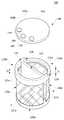
도 2는 본 발명의 예시적인 실시 형태에 따른 주사기용 필터 유닛의 사시도이다.
도 3은 본 발명의 예시적인 실시 형태에 따른 주사기의 분해 사시도이다.
도 4는 본 발명의 예시적인 실시 형태에 따른 주사기의 단면도이다.
도 5는 본 발명의 예시적인 실시 형태에 따른 주사기의 요부 확대 단면도로서, 주사액이 흡입되는 모습을 보인 단면도이다.
도 6은 본 발명의 예시적인 실시 형태에 따른 주사기의 요부 확대 단면도로서, 주사액이 배출되는 모습을 보인 단면도이다.
도 7은 본 발명의 예시적인 실시 형태에 따른 주사기를 구성하는 니들 홀더의 실시예를 보인 배면 절개 사시도이다.
도 8은 본 발명의 예시적인 실시 형태에 따른 주사기의 사시도로서, 주사 바늘의 캡핑 전 모습을 보인 사시도이다.
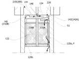
도 9는 본 발명의 예시적인 실시 형태에 따른 주사기의 단면도로서, 주사 바늘의 캡핑 전 모습을 보인 단면도이다.
도 10은 본 발명의 예시적인 실시 형태에 따른 주사기의 사시도로서, 주사 바늘의 캡핑 후 모습을 보인 사시도이다.
도 11은 본 발명의 예시적인 실시 형태에 따른 주사기의 단면도로서, 주사 바늘의 캡핑 후 모습을 보인 단면도이다.1 is a configuration diagram of a syringe according to the prior art.
2 is a perspective view of a filter unit for a syringe according to an exemplary embodiment of the present invention.
3 is an exploded perspective view of a syringe according to an exemplary embodiment of the present invention.
4 is a cross-sectional view of a syringe according to an exemplary embodiment of the present invention.
5 is an enlarged cross-sectional view of a main part of a syringe according to an exemplary embodiment of the present invention, and is a sectional view showing a state in which an injection liquid is sucked.
FIG. 6 is an enlarged cross-sectional view of a main portion of a syringe according to an exemplary embodiment of the present invention, showing a state in which an injection liquid is discharged.
7 is a rear cutaway perspective view showing an embodiment of a needle holder constituting a syringe according to an exemplary embodiment of the present invention.
8 is a perspective view of a syringe according to an exemplary embodiment of the present invention, and is a perspective view showing a state before capping of a needle.
9 is a cross-sectional view of a syringe according to an exemplary embodiment of the present invention, showing a state before capping of a needle.
10 is a perspective view of a syringe according to an exemplary embodiment of the present invention, and is a perspective view showing a state after capping of a needle.
11 is a cross-sectional view of a syringe according to an exemplary embodiment of the present invention, showing the appearance after capping of a needle.
이하, 첨부된 도면을 참조하여 본 발명을 상세히 설명한다. Hereinafter, the present invention will be described in detail with reference to the accompanying drawings.
첨부된 도면은 본 발명의 예시적인 실시 형태를 도시한 것으로, 이는 본 발명의 이해를 돕도록 하기 위해 제공되는 것일 뿐, 이에 의해 본 발명의 기술적 범위가 한정되는 것은 아니다. BRIEF DESCRIPTION OF THE DRAWINGS The accompanying drawings, which are included to provide a further understanding of the invention and are incorporated in and constitute a part of this application, illustrate embodiments of the invention and, together with the description, serve to explain the principles of the invention.
본 명세서에서 '및/또는'은 전후에 나열한 구성요소들 중 적어도 하나 이상을 포함하는 의미로 사용된다. 본 명세서에서 '상에' 설치(형성)된다 라는 것은 제1구성요소 상에 제2구성요소가 직접 설치(형성)되는 것은 물론, 상기 제1구성요소와 제2구성요소의 사이에 제3구성요소가 더 설치(형성)될 수 있다는 의미를 포함한다.In this specification, 'and / or' are used to mean at least one of the elements listed before and after. Herein, "installed" (formed) on this specification means that the second component is directly installed (formed) on the first component, and the third component is provided between the first component and the second component This implies that the element can be installed (formed) further.
본 명세서에서 "제1", "제2", "일측" 및 "타측" 등의 용어는 하나의 구성요소를 다른 구성요소로부터 구별하기 위해 사용되는 것으로서, 각 구성요소가 상기 용어들에 의해 제한되는 것은 아니다.As used herein, the terms "first", "second", "one side" and "other side" are used to distinguish one element from another, It is not.
본 명세서에서 사용되는 용어 '연결', '설치', '결합' 및 '체결' 등은, 두 개의 부재가 착탈(결합과 분리)이 가능하게 결합된 것은 물론, 일체 구조의 의미를 포함한다. 구체적으로, 본 명세서에서 사용되는 용어 '연결', '설치', '결합' 및 '체결' 등은, 예를 들어 강제 끼움 방식(억지 끼움 방식); 홈과 돌기를 이용한 끼움 방식; 및 나사, 볼트, 피스, 리벳 등의 체결 부재를 이용한 체결 방식 등을 통하여, 두 개의 부재가 결합과 분리가 가능하도록 결합되는 것은 물론, 용접이나 접착제, 열 융착 또는 일체적 성형 등을 통하여 두 개의 부재가 결합된 후, 분리가 불가능하게 구성된 의미를 포함한다. 또한, 상기 '설치'의 경우에는 별도의 결합력 없이 두 개의 부재가 적층(안착)되어 있는 의미도 포함한다.As used herein, the terms "connection", "installation", "coupling", and "fastening" mean not only that the two members are capable of being detached (combined and separated), but also include the meaning of an integral structure. Specifically, the terms 'connection', 'installation', 'coupling', and 'engagement' used in the present specification include, for example, a force fitting method (force fitting method); A fitting method using a groove and a projection; And a fastening method using screws, bolts, pieces, rivets, or the like, the two members are combined so as to be capable of being engaged and disengaged, as well as being joined together by welding, adhesive, heat fusion, After the members are combined, it is meant that the separation is impossible. Also, in the case of the 'installation,' it also includes the meaning that two members are stacked (seated) without a separate coupling force.
본 명세서에서 방향을 나타내는 용어로서, 예를 들어 '수직', '수평, '상부', 및 '하부' 등은 어느 한 방향만을 나타내거나, 완전한 '수직'이나 '수평'만을 의미하는 것은 아니다. 그리고 본 명세서에서 형상을 나타내는 용어로서, 예를 들어 '원형' 및 '원통형' 등은 완전한 원형이나 완전한 원통형만을 의미하는 것은 아니다.As used herein, the term 'vertical', 'horizontal', 'upper', and 'lower', for example, are used to denote either one direction or not only a complete 'vertical' or 'horizontal'. As used herein, the terms 'circular' and 'cylindrical' do not mean a complete circle or a complete cylinder.
본 명세서에서 각 도면의 구성요소에 참조번호를 부가함에 있어서, 동일한 구성요소들에 한해서는 비록 다른 도면에 표시되더라도 가능한 한 동일한 번호를 가지도록 하였다. 첨부된 도면에서, 각 구성요소의 영역을 명확하게 표현하기 위하여, 경우에 따라서 두께는 확대하여 나타내었다.In the drawings, the same reference numerals as used in the appended drawings denote the same elements in the drawings. In the accompanying drawings, the thickness is enlarged in some cases in order to clearly express the area of each component.
또한, 첨부된 도면에 표시된 두께, 크기 및 비율 등에 의해 본 발명의 기술적 범위가 제한되는 것은 아니다. 이하, 본 발명을 설명함에 있어서, 관련된 공지의 범용적인 기능 또는 구성에 대한 상세한 설명은 생략한다.
In addition, the technical scope of the present invention is not limited by the thickness, size and ratio shown in the attached drawings. DETAILED DESCRIPTION OF THE PREFERRED EMBODIMENTS In the following description of the present invention, a detailed description of known functions and configurations incorporated herein will be omitted.
먼저, 도 2 내지 도 6을 참조하면, 본 발명에 따른 주사기용 필터 유닛(100, filter unit)은 필터체(120)와, 상기 필터체(120) 상에 설치되는 탄성 밸브(140)를 포함한다. 이때, 상기 필터체(120)는, 주사액이 유입되는 유입부(120A); 주사액이 배출되는 배출부(120B); 상기 유입부(120A)와 배출부(120B)를 구획하는 격벽(122); 및 상기 유입부(120A)와 배출부(120B) 중에서 선택된 하나 이상에 형성된 필터(F)를 포함한다.2 to 6, a
상기 탄성 밸브(140)는 주사액의 흡입 및 배출 과정에 따라 유입부(120A)와 배출부(120B)를 개폐하여 주사액의 흐름을 제어한다. 구체적으로, 도 5를 참조하면, 상기 탄성 밸브(140)는 주사액의 흡입 시, 상기 유입부(120A) 측이 개방되게 하여 주사액이 유입부(120A)로 유입되게 하고, 상기 배출부(120B) 측은 밀폐(차단)되게 한다. 또한, 도 6을 참조하면, 상기 탄성 밸브(140)는 주사액의 배출 시, 상기 배출부(120B) 측이 개방되게 하여 주사액이 배출부(120B)를 통과하여 배출되게 하고, 상기 유입부(120A) 측은 밀폐(차단)되게 한다.The
본 발명에 따르면, 니들 홀더(200, needle holder)의 교체나 조작을 필요로 하지 않고, 주사액의 흡입 및 배출에 따라 상기 필터 유닛(100)이 주사액의 흐름(유입 및 배출)을 제어한다. 그리고 주사액에 포함된 이물질(유리 파편 등)은 흡입 과정 및 배출 과정 중에서 선택된 하나 이상의 과정에서 필터링(filtering)된다.According to the present invention, the filter unit (100) controls the flow (inflow and outflow) of the injection liquid in accordance with the suction and discharge of the injection liquid without requiring replacement or manipulation of the needle holder (200). The foreign matter (glass fragments, etc.) contained in the injection solution is filtered in at least one process selected from the suction process and the discharge process.
본 발명에 따른 필터 유닛(100)은 주사기에 설치되는 것이라면, 그 설치 위치는 특별히 제한되지 않는다. 필터 유닛(100)은, 예를 들어 니들 홀더(200)에 삽입, 설치되거나, 실린더(300, cylinder)의 네크부(310, neck part)에 삽입, 설치될 수 있다. 필터 유닛(100)은, 바람직하게는 도면에 도시한 바와 같이, 니들 홀더(200)의 내부에 삽입, 설치될 수 있다.If the
이하, 본 발명의 예시적인 실시 형태를 설명하면 다음과 같다. 이하, 본 발명의 예시적인 실시 형태를 설명함에 있어, 필터 유닛(100)이 니들 홀더(120)에 삽입, 설치되는 경우를 예로 들어 설명한다.Hereinafter, an exemplary embodiment of the present invention will be described. In the following description of an exemplary embodiment of the present invention, a case where the
상기 필터체(120)는 격벽(122)에 의해 구획된 유입부(120A)와 유출부(120B)를 포함한다. 이때, 상기 유입부(120A)와 배출부(120B) 중에서 선택된 하나 이상에는 필터(F)가 형성되어 있다. 상기 필터(F)는, 구체적으로 유입부(120A)에 형성되거나 유출부(120B)에 형성될 수 있으며, 다른 형태에 따라서는 유입부(120A)와 배출부(120B) 둘 모두에 형성될 수 있다. 상기 필터(F)는, 바람직하게는 도면에 예시한 바와 같이 유입부(120A)와 배출부(120B) 둘 모두에 형성될 수 있다.The
본 발명에서, 필터(F)는 이물질을 필터링(여과)할 수 있는 것이라면 특별히 제한되지 않는다. 상기 필터(F)는, 예를 들어 앰플(A, 도 1 참조)의 개봉 시 발생되는 유리 파편 등을 필터링할 수 있는 것이라면 좋다. 상기 필터(F)는, 예를 들어 10㎛ 이하, 7㎛ 이하, 또는 5㎛ 이하의 포어(pore)를 가지는 다공질 필터로부터 선택될 수 있다. 상기 필터(F)는, 구체적인 예를 들어 부직포 필터나 종이 필터 등으로부터 선택될 수 있으나, 이에 한정되는 것은 아니다.In the present invention, the filter (F) is not particularly limited as long as it can filter (filter) foreign matter. The filter F may be any filter capable of filtering glass fragments or the like generated when the ampule A (see Fig. 1) is opened, for example. The filter F may be selected from a porous filter having a pore of, for example, 10 mu m or less, 7 mu m or less, or 5 mu m or less. The filter F may be selected from, for example, a nonwoven filter or a paper filter, but is not limited thereto.
도 2를 참조하면, 상기 필터체(120)는 원통형의 형상을 가지는 것이 바람직하다. 상기 필터체(120)는, 본 발명의 예시적인 형태에 따라서 원통형 본체(121)와, 상기 원통형 본체(121)의 내부에 설치된 격벽(122)을 포함한다. 상기 원통형 본체(121)는, 구체적으로 도면에 예시한 바와 같이 원통형의 측벽(120a)과 원형의 바닥(120b)을 가지며, 상부는 개구되어 있다. 상기 격벽(122)은 원통형 본체(121)를 유입부(120A)와 배출부(120B)로 구획한다. 본 발명에서, '원통형'과 '원형'은 완전한 원통형과 완전한 원형만을 의미하는 것은 아니다. 이때, 상기 측벽(120a)과 바닥(120b) 중에서 선택된 하나 이상은 필터(F)로 구성된다. 구체적으로, 상기 측벽(120a)이 필터(F)로 구성되거나, 상기 바닥(120b)이 필터(F)로 구성될 수 있으며, 다른 형태에 따라서는 상기 측벽(120a)과 바닥(120b) 둘 모두가 필터(F)로 구성될 수 있다. 도면에서는, 측벽(120a)이 필터(F)로 구성된 모습을 예시하였다.Referring to FIG. 2, it is preferable that the
또한, 상기 원통형 본체(121)는 원형의 상부 프레임(121a); 원형의 하부 프레임(121b); 및 상기 상부 프레임(121a)과 하부 프레임(121b)을 연결하여 지지하는 지지 프레임(121c)을 포함할 수 있다. 그리고 상기 프레임(121a)(121b)(121c)에 필터(F)가 부착되어 측벽(120a) 및/또는 바닥(120b)이 형성될 수 있다.Further, the
본 발명에서, 상기 필터체(120)의 재질은 특별히 제한되지 않는다. 예를 들어, 상기 프레임들(121a)(121b)(121c)과 격벽(122)은 플라스틱재 또는 금속재로 구성될 수 있으며, 이들은 예시적인 형태에 따라서 비용, 경량 및 가격 등에서 유리한 플라스틱재로 구성될 수 있다. 그리고 하나의 예시에서, 상기 측벽(120a)은 필터(F)로 구성되고, 상기 바닥(120b)은 플라스틱재로 구성될 수 있다.In the present invention, the material of the
상기 상부 프레임(121a)은 니들 홀더(200)의 내부 벽면에 밀착되어 패킹(packing)된다. 이때, 상부 프레임(120a)이 니들 홀더(200)의 내부 벽면에 밀착될 수 있도록, 상기 상부 프레임(121a)의 외경은 니들 홀더(200)의 내경과 동일하거나 약간 크게 형성될 수 있다. 이에 따라, 상기 상부 프레임(121a)은 니들 홀더(200)의 내부에 강제 끼움 결합되어 패킹될 수 있다. 이와 같이, 상부 프레임(121a)이 니들 홀더(200)의 내부 벽면에 밀착 패킹되어, 필터체(120)와 니들 홀더(200)는 결합력을 가지면서 주사액은 통과되지 않는다. 즉, 니들 홀더(200)의 내부 벽면과 상부 프레임(121a)의 사이로는 주사액이 통과되지 않는다.The
또한, 상기 하부 프레임(121b)의 외경은 상부 프레임(120a)의 외경보다 작다. 구체적으로, 상기 하부 프레임(121b)의 외경은 니들 홀더(200)의 내경보다 작게 형성되어, 이들 사이에는 유로가 형성된다. 이에 따라, 니들 홀더(200)의 내부 벽면과 하부 프레임(121a)의 사이로는 주사액이 통과된다. 도 5 및 도 6에 표시된 화살표는 주사액의 흐름을 나타낸다.The outer diameter of the
또한, 상기 유입부(120A)는 주사액의 흡입 시, 탄성 밸브(140)가 휘어져 개방되게 하는 단차(124)가 형성될 수 있다. 보다 구체적으로, 상기 상부 프레임(121a)의 일측에는 주사액의 흡입 시, 탄성 밸브(140)가 휘어져 개방되게 하는 단차(124)가 형성될 수 있다. 즉, 도 2를 참조하면, 상부 프레임(121a)의 수직 방향 두께에 있어서, 유입부(120A)의 두께(TA)는 배출부(120B)의 두께(TB)보다 작게 형성되어, 유입부(120A) 측에는 단차(124)가 마련된다. 이에 따라, 주사액의 흡입 시, 유입부(120A) 측에서는 탄성 밸브(140)가 유입되는 방향(도면에서 아래쪽 방향)으로 휘어져 주사액이 유입된다.In addition, the
상기 탄성 밸브(140)는 필터체(120) 상에 설치되어 유입부(120A)와 배출부(120B)를 개폐시킨다. 상기 탄성 밸브(140)는, 예시적인 형태에 따라서 유입부(120A) 및 배출부(120B) 상에 설치되는 탄성 플레이트(142)와; 상기 탄성 플레이트의 일측에 돌출 형성된 돌출부(144)를 포함한다. 상기 돌출부(144)는 적어도 하나 이상이며, 이는 바람직하게는 복수 개이다. 이러한 돌출부(144)는 주사액의 배출 통로(143)를 형성시킨다. 구체적인 예를 들어, 상기 돌출부(144)는 탄성 플레이트(142) 상에 복수 개 돌출 형성되어, 돌출부들(144)의 사이에는 배출 통로(143)가 형성된다. 주사액의 배출 시, 주사액은 상기 배출 통로(143)를 통해 배출된다.The
본 발명에서, 상기 탄성 밸브(140)는 탄성력을 가지는 것이면, 그 재질은 특별히 제한되지 않는다. 상기 탄성 밸브(140)는, 예를 들어 실리콘, 고무, 합성수지 엘라스토머(elastomer), 및 합성수지 발포 폼(foam) 등으로부터 선택될 수 있다. 또한, 상기 탄성 플레이트(142)는, 예를 들어 원반형의 형상으로서, 이는 필터체(120)의 형상과 대응된다. 아울러, 상기 돌출부(144)는 탄성 플레이트(142)의 일측, 즉 배출부(120B) 측에 형성된다. 보다 구체적으로, 상기 탄성 플레이트(142)는 필터체(120)의 유입부(120A)에 대응되는 유입측 플레이트(142A)와, 필터체(120)의 배출부(120B)에 대응되는 배출측 플레이트(142B)로 구분되며, 이때 상기 돌출부(144)는 배출측 플레이트(142B) 상에 복수 개 형성된다. 그리고 상기 돌출부(144)는 배출측 플레이트(142B)에 형성되되, 필터체(120)와 접촉되는 면의 반대 쪽 면(도면에서 위쪽 면)에 돌출 형성된다. 이러한 돌출부(144)는 배출 통로(143)를 형성시킬 수 있는 것이라면, 그 형상이나 개수는 제한되지 않는다. 도 2는 대략 반구형의 돌출부(144)가 3개 형성된 모습을 예시한 것이다.In the present invention, the material of the
도 4 내지 6을 참조하여, 위와 같은 본 발명에 따른 필터 유닛(100)의 작동 과정을 설명하면 다음과 같다. 도 5 및 도 6은 도 4의 "A" 부분 확대 단면도로서, 도 5는 흡입 과정을 보인 것이고, 도 6은 배출 과정을 보인 것이다.The operation of the
먼저, 도 4 및 도 5를 참조하면, 플런저(400)를 잡아 당겨 흡입력을 발생시키면, 주사액은 주사 바늘(211)을 통해 흡입된다. 이때, 흡입력에 의해, 상기 탄성 밸브(140)의 유입측 플레이트(142A)는 흡입되는 방향을 향하여, 즉 필터체(120)가 있는 방향(도면에서 아래쪽)으로 휘어져 주사액이 유입된다. 보다 구체적으로, 필터체(120)의 유입부(120A)에는 전술한 바와 같이 단차(124)가 형성되어 있으므로, 탄성 밸브(140)의 유입측 플레이트(142A)는 탄성력에 의해 도면의 아래쪽 방향으로 휘어진다. 이에 따라, 유입부(120A)가 개방되어 유입 공간(S1)이 형성되고, 주사액은 상기 유입 공간(S1)을 따라 유입부(120A)로 유입된다. 이후, 주사액은 유입부(120A)를 통과하면서 필터링된다. 이때, 예를 들어 측벽(120a)이 필터(F)로 구성된 경우, 유입된 주사액은 측벽(120a)을 통과하면서 필터링된다. 그리고 측벽(120a)을 통과한 주사액은 니들 홀더(200)의 내부 벽면과 하부 프레임(121b)의 사이를 거쳐 실린더(300)로 유입, 저장된다.Referring to FIGS. 4 and 5, when the
또한, 위와 같은 흡입 과정에서, 배출부(120B) 쪽은 밀폐(차단)된다. 구체적으로, 흡입력이 발생되면, 탄성 밸브(140)는 흡입력에 의해 필터체(120) 쪽으로 밀착되는데, 이때 탄성 밸브(140)의 배출부(120B) 쪽, 즉 배출측 플레이트(142B)는 필터체(120)의 상부 프레임(121a)에 밀착되어 배출부(120B)로는 주사액이 유입되지 않는다.Further, in the suction process as described above, the
한편, 도 6을 참조하면, 플런저(400)를 밀어 토출력을 발생시키면, 주사액은 상기와는 반대의 동작으로 배출부(120B)를 통과한 후, 주사 바늘(211)을 통해 외부로 배출된다. 구체적으로, 토출력이 발생되면, 실린더(300)에 저장된 주사액은 니들 홀더(200)의 내부 벽면과 하부 프레임(121b)의 사이를 거쳐, 배출부(120B) 측의 측벽(120a)을 통과한 다음, 상기 배출 통로(143)를 따라 주사 바늘(211)로 공급된다. 보다 구체적으로, 토출력이 발생되면, 탄성 밸브(140)는 탄성력에 의해 니들 홀더(200) 쪽(도면에서 위쪽 방향)으로 밀착되는데, 이때 배출부(120B) 측에서는 탄성 밸브(140)와 필터체(120)의 사이에, 즉 배출측 플레이트(142B)와 상부 프레임(121a)의 사이에 배출 공간(S2)이 형성된다. 주사액은 상기 배출 공간(S2)을 통과한 다음, 배출 통로(143)를 따라 주사 바늘(211)로 공급되어 외부로 배출된다. 이때, 상기 배출 통로(143)는 상기한 바와 같이 배출측 플레이트(142B) 상에 돌출 형성된 복수개의 돌출부(144)에 의해 형성된 것으로서, 이러한 배출 통로(143)를 통해 주사액이 배출된다.6, when the
또한, 위와 같은 배출 과정에서, 유입부(120A) 쪽은 밀폐(차단)된다. 구체적으로, 토출력이 발생되면, 상기한 바와 같이 탄성 밸브(140)는 니들 홀더(200) 쪽으로 밀착되는데, 이때 탄성 밸브(140)의 유입부(120A) 쪽, 즉 유입측 플레이트(142A)는 차단부(220)에 밀착되어 유입부(120A) 쪽으로는 주사액이 배출되지 않는다.Further, in the above discharge process, the
본 발명에서, 상기 차단부(220)는 주사액의 배출 시, 탄성 밸브(140)의 유입측 플레이트(142A)에 밀착되어 유입부(120A)를 통해 주사액이 배출되는 것을 방지할 수 있는 것이면 좋다. 상기 차단부(220)는 필터 유닛(100)의 설치 위치에 따라, 예를 들어 도면에 도시한 바와 같이 니들 홀더(200)에 돌출, 형성된 것이나, 실린더(300)의 네크부(310)에 돌출, 형성된 것일 수 있다.In the present invention, the blocking
또한, 상기 차단부(220)는 별개의 부재로 구성될 수 있다. 이때, 예시적인 형태에 따라서, 본 발명에 따른 필터 유닛(100)은 필터체(120) 및 탄성 밸브(140)를 포함하되, 경우에 따라서 상기와 같은 차단부(220)를 가지는 별도의 유입측 밀폐 부재를 더 포함할 수 있다.Further, the blocking
상기 차단부(220)는 유입부(120A) 쪽으로 주사액이 배출되는 것을 방지할 수 있는 것이라면, 그의 구조, 형상 및 재질 등은 제한되지 않는다. 도 7에는 상기 차단부(220)의 예시적인 실시예가 도시되어 있다. 도 7에 보인 바와 같이, 상기 차단부(220)는 예를 들어 반원형의 형상으로서, 상기 니들 홀더(200)에 형성될 수 있다. 상기 차단부(220)는, 예를 들어 플라스틱재로 구성되거나, 탄성 밸브(140)와 같이 탄성력을 가지는 재질로 구성될 수 있다.The structure, shape, material, and the like of the blocking
또한, 앞서 언급한 바와 같이, 이물질(유리 파편 등)의 필터링은, 주사액의 흡입 과정에서 진행되거나, 배출 과정에서 진행될 수 있으며, 다른 형태에 따라서는 흡입 및 배출의 두 과정 모두에서 진행될 수 있다. 아울러, 상기 필터(F)는 필터체(120)의 측벽(120a) 및/또는 바닥(120b)에 형성될 수 있는데, 이때 필터(F)의 형성 위치에 따라 주사액의 흐름 경로가 다양하게 구현될 수 있다. 예를 들어, 상기 필터(F)가 측벽(120a)에 형성된 경우, 주사액은 흡입 과정에서, 유입부(120A)의 측벽(120a) --> 니들 홀더(200)의 내부 벽면과 하부 프레임(121b)의 사이 --> 실린더(300)의 흡입 경로를 따라 흡입된다. 또한, 필터(F)가 바닥(120b)에 형성된 경우, 주사액은 흡입 과정에서, 유입부(120A)의 바닥(120b) --> 실린더(300)를 흡입 경로를 따라 흡입된다. 다른 예를 들어, 상기 필터(F)가 측벽(120a) 및 바닥(120b) 둘 모두에 형성된 경우, 주사액은 상기 두 가지 모두의 흡입 경로를 통해 흡입될 수 있다. 그리고 배출 과정에서는 위와 반대되는 경로를 따라 배출된다.Further, as mentioned above, the filtering of foreign matter (glass fragments, etc.) can proceed in the process of inhalation of the injection liquid or progress in the process of discharge, and may proceed in both of the processes of inhalation and exhalation depending on other forms. The filter F may be formed on the
이상에서 설명한 본 발명에 따른 필터 유닛(100)은 주사기에 설치되어 주사액을 효과적으로 필터링한다. 본 발명에 따른 필터 유닛(100)은, 전술한 바와 같이 주사기의 니들 홀더(200)에 설치되거나, 실린더(300)의 네크부(310)에 설치되어 유용하게 사용될 수 있다. 이하, 본 발명에 따른 주사기를 설명한다.The
한편, 본 발명에 따른 주사기는 상기한 바와 같은 본 발명의 필터 유닛(100)을 포함한다. 본 발명에 따른 주사기는, 상기 본 발명의 필터 유닛(100)을 포함하는 것이라면 특별히 제한되지 않는다.Meanwhile, the syringe according to the present invention includes the
도 3 및 도 4에는 본 발명에 따른 주사기의 예시적인 실시 형태가 도시되어 있다.Figures 3 and 4 show an exemplary embodiment of a syringe according to the present invention.
도 3 및 도 4를 참조하면, 본 발명에 따른 주사기는, 상기한 바와 같은 본 발명의 필터 유닛(100)과, 주사 바늘(211)이 결합된 니들 홀더(200)를 포함할 수 있다. 또한, 본 발명에 따른 주사기는, 통상과 같이 실린더(300) 및 플런저(400)를 더 포함할 수 있다. 이때, 상기 실린더(300)와 플런저(400)는 통상과 같이 구성될 수 있다. 상기 실린더(300)는 원통형의 형상을 가지며, 일측에는 네크부(310)가 형성된 구조를 가질 수 있다. 또한, 상기 플런저(400)는 실린더(300)의 내부를 왕복(진퇴) 운동하면서 흡입력 및 토출력을 갖게 하는 것이면 좋다. 아울러, 본 발명에 따른 주사기는 마감 캡(500)을 더 포함할 수 있다. 상기 마감 캡(500)은 주사 바늘(211)을 보호하는 것으로서, 이는 도면에 도시된 바와 같이 주사 바늘(310)을 커버링(covering) 상태에서 니들 홀더(200)에 결합된다.3 and 4, the syringe according to the present invention may include the
상기 필터 유닛(100)은 전술한 바와 같이 니들 홀더(200)의 내부에 설치되거나, 실린더(300)의 네크부(310)에 설치될 수 있다. 필터 유닛(100)은, 바람직하게는 니들 홀더(200)의 내부에 삽입, 설치될 수 있다.The
상기 니들 홀더(200)는 통상과 같은 구조를 가질 수 있다. 상기 니들 홀더(200)는, 예시적인 실시 형태에 따라서 니들 결합부(210)와, 상기 니들 결합부(210)로부터 연장 형성된 조립부(230)를 포함하고, 상기 니들 결합부(210)의 일측에는 주사 바늘(211)이 결합된 구조를 가질 수 있다. 이때, 상기 조립부(230)는, 예를 들어 원통형으로서, 여기에는 필터 유닛(100)이 삽입, 설치될 수 있다. 또한, 조립부(230)에는 실린더(300)의 네크부(310)가 끼움 결합될 수 있다.The
또한, 본 발명의 예시적인 실시 형태에 따라서, 상기 니들 홀더(200)는 차단부(220)를 더 포함할 수 있다. 상기 차단부(220)는 전술한 바와 같이 주사액의 배출 시, 상기 필터 유닛(100)을 구성하는 탄성 밸브(140)의 일측에 밀착, 즉 유입측 플레이트(142A)에 밀착되는 것으로서, 이는 유입부(120A)를 통해 주사액이 배출되는 것을 방지할 수 있는 것이면 좋다. 이러한 차단부(220)는 상기 예시한 바와 같이 반원형의 형상을 가질 수 있다. 상기 차단부(220)는, 구체적으로 도 7에 도시한 바와 같이, 반원형의 형상을 가지되, 상기 니들 결합부(210)로부터 일체로 돌출, 형성될 수 있다. 상기 차단부(220)는, 다른 예를 들어 상기 조립부(230)의 내부 벽면을 따라 반원형의 형상으로 돌출, 형성될 수 있다.Further, according to an exemplary embodiment of the present invention, the
아울러, 상기 니들 홀더(200)는 경우에 따라서 필터체(120)의 이탈을 방지할 수 있는 스토퍼(232, stopper)를 더 포함할 수 있다. 구체적으로, 상기 니들 홀더(200)의 내부 벽면에는 스토퍼(232)가 형성될 수 있다. 전술한 바와 같이, 필터체(120)를 구성하는 상부 프레임(121a)은 니들 홀더(200)의 내부 벽면에 밀착, 패킹되어, 필터체(120)와 니들 홀더(200)는 결합력을 갖는다. 이에 따라, 주사액의 배출 시, 플런저(400)의 토출력이 발생하더라도 필터체(120)는 이탈되지 않는다. 그러나 경우에 따라 플런저(400)의 토출력이 너무 강한 경우, 필터체(120)는 탄성 밸브(140) 쪽(도면에서 위쪽 방향)으로 이탈될 수 있다. 이 경우, 필터체(120)의 상단과 탄성 밸브(140)의 밀착으로 인해 주사액의 배출이 용이하지 않다. 또한, 흡입 과정에서도, 경우에 따라 플런저(400)의 강한 흡입력으로 인해 필터체(120)의 이탈이 발생될 수 있다.In addition, the
상기 스토퍼(232)는 위와 같은 이탈을 방지한다. 구체적으로, 상기 스토퍼(232)는 플런저(400)의 강한 토출력 및 흡입력에 의해 발생될 수 있는 필터체(120)의 이탈을 방지한다. 도면에 예시한 바와 같이, 상기 스토퍼(232)는 니들 홀더(200)의 내부 벽면에 돌출, 형성되되, 필터체(120)의 상부 프레임(121a) 및/또는 하부 프레임(121b)에 밀착되는 구조로 형성될 수 있다.The
한편, 본 발명에 따른 주사기는 선택적인 구성요소로서, 바늘 캡핑 유닛(10, needle capping unit)을 더 포함할 수 있다. 도 8 내지 도 11에는 상기 바늘 캡핑 유닛(10)의 예시적인 실시예가 도시되어 있다.Meanwhile, the syringe according to the present invention may further include a
상기 바늘 캡핑 유닛(10)은 주사액의 투여 후에 주사 바늘(211)을 캡핑(capping)할 수 있는 것으로서, 이는 상기 니들 홀더(200)에 결합된다. 상기 바늘 캡핑 유닛(10)은, 생체(인체 등)에 주사액을 투여한 후에 주사 바늘(211)을 안전하게 캡핑할 수 있는 구조를 갖는 것이라면 특별히 제한되지 않는다. 이러한 바늘 캡핑 유닛(10)에 의해 병원균의 감염을 예방할 수 있다. 주사기의 사용자, 예를 들어 의사나 간호사 등의 의료종사자는 병원균의 감염에 노출될 수 있다. 구체적으로, 주사기는 주사액의 투여 후, 안전하게 폐기되어야 하나, 사용자의 부주의로 인해 주사 바늘(211)이 인체에 접촉되거나 찔러지는 경우, 병원균에 감염될 수 있다. 상기 바늘 캡핑 유닛(10)은 이러한 감염을 방지한다. 본 발명에서, '캡핑'은 주사 바늘(211)의 적어도 말단을 감싸 인체와의 접촉을 방지할 수 있는 것이면 좋다.The
상기 바늘 캡핑 유닛(10)은, 본 발명의 예시적인 실시 형태에 따라서, 상기 니들 홀더(200)에 결합되는 안전 캡(12); 상기 안전 캡(12)에 설치된 캡핑 부재(16); 및 상기 캡핑 부재(16)의 이탈을 방지하는 이탈 방지 부재(18)를 포함할 수 있다.The
상기 안전 캡(12)은 니들 홀더(200)의 외주연(외부 둘레)에 끼움, 결합되며, 이는 예를 들어 원통형의 형상을 갖는다. 이러한 안전 캡(12)에는 주사 바늘(211)이 관통되는 관통홀(12a)이 형성되어 있다. 또한, 상기 안전 캡(12)에는 캡핑 부재(16)가 설치되어 있다. 이때, 상기 안전 캡(12)에는 안착홈(12b)과 삽입홈(12c)이 형성될 수 있다. 상기 안착홈(12b)은 안전 캡(12)의 길이 방향(도면에서 수직 방향)을 따라 소정의 깊이로 형성될 수 있다. 이러한 안착홈(12b)에는 캡핑 부재(16)의 하측이 안착된다. 보다 구체적으로, 상기 안착홈(12b)에는 캡핑 부재(16)의 지지부(16b)가 안착된다. 상기 삽입홈(12c)은 안전 캡(12)의 폭 방향(도면에서 수평 방향)으로 형성될 수 있다. 이러한 삽입홈(12c)에는 캡핑 부재(16)의 상측이 삽입된다. 보다 구체적으로, 상기 삽입홈(12c)에는 캡핑 부재(16)의 캡핑부(16c)가 삽입된다.The
상기 안전 캡(12)의 재질은 제한되지 않는다. 상기 안전 캡(12)은, 예를 들어 플라스틱재, 금속재, 종이재 또는 펄프재 등으로 구성될 수 있다.The material of the
상기 캡핑 부재(16)는 안전 캡(12)에 설치되며, 이는 주사액의 투여 후에 주사 바늘(211)의 말단을 캡핑한다. 상기 캡핑 부재(16)는 주사 바늘(211)의 캡핑 시, 주사 바늘(211)의 말단 상에 밀착되거나, 주사 바늘(211)의 말단을 커버링(covering)하는 구조로 캡핑하여 인체와의 접촉을 방지할 수 있는 것이면 좋다.The capping
상기 캡핑 부재(16)는, 앞서 언급한 바와 같이 예를 들어 지지부(16b)와, 상기 지지부(16b)로부터 연장되어 절곡 형성된 캡핑부(16c)를 포함할 수 있다. 전술한 바와 같이, 상기 지지부(16b)는 안착홈(12b)에 안착되고, 상기 캡핑부(16c)는 삽입홈(12c)에 삽입된다. 이때, 상기 캡핑부(16c)는 삽입홈(12c)에 삽입되면서 주사 바늘(211)의 말단을 캡핑한다.The capping
상기 캡핑 부재(16)는, 일례를 들어 돌기와 홈 구조를 통해 상기 안전 캡(12)과 결합될 수 있다. 보다 구체적인 예를 들어, 상기 캡핑 부재(16)의 일측 말단(도면에서 하측)에는 돌기 형태의 결합부(16d)가 형성되고, 상기 안전 캡(12)에는 결합홈(도시하지 않음, 12d)이 형성되어, 상기 결합부(16d)와 결합홈(12d)의 끼움 결합에 의해, 캡핑 부재(16)와 안전 캡(12)의 결합력이 도모될 수 있다.The capping
또한, 상기 캡핑 부재(16)의 말단(도면에서 상측)에는 가이드 홈(16a)이 형성될 수 있다. 구체적으로, 캡핑 부재(16)의 말단은 캡핑 전에 주사 바늘(211)의 몸체에 밀착될 수 있는데, 이때 주사 바늘(211)의 몸체와 접촉되는 상측 말단, 즉 캡핑부(16c)의 말단에는 가이드 홈(16a, guide groove)이 형성될 수 있다. 이에 따라, 가이드 홈(16a)에 주사 바늘(211)이 파지되어, 캡핑 부재(16)와 주사 바늘(211)의 밀착력이 향상되고, 캡핑 조작이 용이해질 수 있다. 상기 가이드 홈(16a)은 다양한 형상을 가질 수 있으며, 이는 예를 들어 'V'자형, 'U'자형, 'C'자형 또는 'ㄷ'자형 등의 형상을 가질 수 있다. 도면에서는 'V'자형의 가이드 홈(16a)을 예시하였다.A
상기 캡핑 부재(16)는, 예를 들어 금속재 또는 플라스틱재 등으로부터 선택될 수 있으며, 이는 또한 소정의 탄성(신축성)을 가질 수 있다. 상기 캡핑 부재(16)는, 일례를 들어 소정의 탄성을 가지는 SUS 재질로 구성될 수 있다.The capping
상기 이탈 방지 부재(18)는 캡핑 부재(16)의 이탈을 방지하기 위한 것으로서, 이는 구체적으로 주사 바늘(211)의 캡핑 시, 상기 캡핑 부재(16)가 주사 바늘(211)의 말단을 이탈하는 것을 방지한다. 보다 구체적으로, 주사 바늘(211)의 캡핑 시, 캡핑 부재(16)의 말단, 즉 캡핑부(16c)는 주사 바늘(211)의 말단에 밀착되어야 하는데, 이때 상기 이탈 방지 부재(18)는 이탈 간격을 유지하여, 캡핑부(16c)가 주사 바늘(211)의 말단을 오버(over)하여 벗어나는 것을 방지한다.The
상기 이탈 방지 부재(18)는 캡핑 부재(16)의 이탈을 방지할 수 있는 것이라면, 그의 구조, 형상 및 재질 등은 제한되지 않는다. 상기 이탈 방지 부재(18)는, 예를 들어 줄(string), 밴드(band), 와이어(wire) 또는 스프링(spring) 등으로 구성될 수 있다. 상기 이탈 방지 부재(18)는, 구체적인 예를 들어 니들 홀더(200)에 감겨진 줄이 사용될 수 있으며, 보다 구체적인 일례를 들어 낚시 줄을 사용할 수 있으나, 이에 한정되는 것은 아니다. 또한, 상기 이탈 방지 조절 부재(18)는 캡핑 부재(16)의 이탈을 방지할 수 있는 것이라면, 소정의 신축성을 가져도 좋다.The structure, shape, material, etc. of the
상기 이탈 방지 부재(18)는, 예를 들어 안전 캡(12)에 연결되거나, 캡핑 부재(16)에 직접 연결될 수 있다. 보다 구체적으로, 상기 이탈 방지 부재(18)의 일측은 안전 캡(12)이나 캡핑 부재(16)에 연견되고, 타측은 니들 홀더(200)에 연결될 수 있다. 도면에서는, 이탈 방지 부재(18)의 일측은 안전 캡(12)에 연결되고, 타측은 니들 홀더(200)의 니들 결합부(210)에 연결된 모습을 예시하였다.The
또한, 상기 바늘 캡핑 유닛(10)은 선택적으로 보호 캡(14)을 더 포함할 수 있다. 상기 보호 캡(14)은 안전 캡(12)과 캡핑 부재(16)를 보호하면서 바늘 캡핑 유닛(10)의 사용성을 향상시킬 수 있다. 상기 보호 캡(14)은 안전 캡(12)의 외주연에 끼움, 결합되며, 이는 예를 들어 원통형의 형상으로서 안전 캡(12)의 형상과 대응된다. 이러한 보호 캡(14)에는 주사 바늘(211)이 관통되는 관통공(14a)이 형성되어 있다. 아울러, 상기 보호 캡(14)에는 출입홀(14b)이 형성될 수 있다. 상기 출입홀(14b)은 보호 캡(14)의 길이 방향(도면에서 수직 방향)을 따라 소정 길이로 형성될 수 있다. 상기 출입홀(14b)을 통해 캡핑 부재(16)가 출입된다. 상기 보호 캡(14)의 재질은 제한되지 않으며, 이는 안전 캡(12)과 동일한 재질로서, 예를 들어 플라스틱재, 금속재, 종이재 또는 펄프재 등으로 구성될 수 있다.In addition, the
도 8 내지 도 11을 참조하여, 상기 바늘 캡핑 유닛(10)의 사용 방법을 설명하면 다음과 같다. 도 8 및 도 9는 캡핑 전의 모습이고, 도 10 및 도 11은 캡핑 후의 모습이다.The method of using the
먼저, 도 8 및 도 9를 참조하면, 캡핑 전에, 상기 바늘 캡핑 유닛(10)은 니들 홀더(200)의 니들 결합부(210)에 설치되어 있다. 구체적으로, 니들 결합부(210)의 외주연에 안전 캡(12)이 결합되고, 상기 안전 캡(12)의 외주연에 보호 캡(14)이 결합되어 있다. 이때, 상기 주사 바늘(211)은 안전 캡(12)의 관통홀(12a)과 보호 캡(14)의 관통공(14a)을 관통하여 외부로 노출되어 있다. 즉, 도 8 및 도 9는 주사액의 투여 전의 모습이다.8 and 9, before capping, the
또한, 상기 이탈 방지 부재(18)는 안전 캡(12)의 하부에 설치된다. 보다 구체적으로, 상기 이탈 방지 부재(18)는 안전 캡(12)의 하부에 설치되되, 니들 홀더(200)의 외주연에 감겨져 있다. 아울러, 상기 캡핑 부재(16)는 안전 캡(12)에 설치되어 있되, 상기 캡핑 부재(16)의 말단, 즉 캡핑부(16c)는 안전 캡(12)의 내측에서 주사 바늘(211)의 몸체에 밀착되어 있다. 보다 구체적으로, 캡핑 부재(16)의 가이드 홈(16a)에 주사 바늘(211)의 몸체가 삽입(파지)되어 있다.Further, the
다음으로, 도 10 및 도 11을 참조하면, 주사액의 투여 후에, 상기 보호 캡(14)을 잡아당겨 주사 바늘(211)을 캡핑한다. 구체적으로, 보호 캡(14)을 잡아 당겨 안전 캡(12)이 캡핑 부재(16)와 함께 주사 바늘(211)의 말단 쪽(도면에서 위쪽)으로 이동되게 한다. 이때, 가이드 홈(16a)에 의해, 캡핑 부재(16)는 이탈됨이 없이 주사 바늘(211)의 길이 방향(도면에서 수직 방향)을 따라 가이드되면서 이동된다. 이후, 캡핑부(16c)가 주사 바늘(211)의 말단에 위치되면, 캡핑부(16c)는 안전 캡(12)의 삽입홈(12c)에 삽입되면서 주사 바늘(211)의 말단을 캡핑한다. 캡핑부(16c)는 그의 탄성력에 의해 삽입홈(12c)에 용이하게 삽입될 수 있다. 이에 따라, 주사 바늘(211)은 안전 캡(12)과 캡핑 부재(16)의 의해 감싸져 캡핑된다.Next, referring to FIGS. 10 and 11, after the administration of the injection liquid, the
전술한 바와 같이, 상기 이탈 방지 부재(18)는 캡핑 부재(16)의 이탈을 방지한다. 즉, 잡아당기는 힘이 너무 강한 경우, 상기 캡핑 부재(16)가 주사 바늘(211)의 말단을 지나칠 수 있는데, 이때 이탈 방지 부재(18)는 캡핑 부재(16)의 이동 간격(거리)을 조절하여, 지나치게 이동되는 것을 방지한다. 상기 이탈 방지 부재(18)의 길이는 주사 바늘(211)의 길이에 따라 다양하게 설계될 수 있다.As described above, the
아울러, 상기에서는 보호 캡(14)을 잡아 당겨 주사 바늘(211)을 캡핑하는 경우를 예로 들어 설명하였으나, 전술한 바와 같이 본 발명에서 보호 캡(14)은 선택적인 구성요소이다. 이러한 보호 캡(14)을 설치하지 않는 경우에는, 상기 안전 캡(12)을 잡아당겨 캡핑할 수 있다.In the above description, the
또한, 경우에 따라서, 상기 보호 캡(14)은 캡핑 후, 안전 캡(12)으로부터 분리될 수 있다. 이때, 상기 안전 캡(12)과 캡핑 부재(16)는 주사 바늘(211)과 함께 폐기될 수 있으나, 상기 보호 캡(14)은 캡핑 후, 안전 캡(12)으로부터 분리, 수거되어 재활용될 수 있다.Also, if desired, the
이상에서 설명한 본 발명에 따르면, 전술한 바와 같이 니들 홀더(200)의 교체나 조작을 필요로 하지 않고, 주사액의 흡입 및 배출에 따라 상기 필터 유닛(100)이 주사액의 흐름(유입 및 배출)을 자동으로 제어한다. 그리고 주사액에 포함된 이물질(유리 파편 등)은 흡입 과정 및/또는 배출 과정에서 효과적으로 필터링된다. 아울러, 본 발명의 상기 필터 유닛(100)은 종래의 필터링 구조에 비해 구조적으로 간단하여 제조비용이 낮다.
As described above, according to the present invention, the
10 : 바늘 캡핑 유닛 12 : 안전 캡
14 : 보호 캡 16 : 캡핑 부재
18 : 이탈 방지 부재 100 : 필터 유닛
120 : 필터체 120A : 유입부
120B : 배출부 120a : 측벽
120b : 바닥 121 : 원통형 본체
121a : 상부 프레임 121b : 하부 프레임
121c : 지지 프레임 122 : 격벽
124 : 단차 140 : 탄성 밸브
142 : 탄성 플레이트 143 : 배출 경로
144 : 돌출부 200 : 니들 홀더
210 : 니들 결합부 211 : 주사 바늘
220 : 차단부 230 : 조립부
232 : 스토퍼 300 : 실린더
310 : 네크부 400 : 플런저
500 : 마감 캡 F : 필터
S1 : 유입 공간 S2 : 배출 공간10: Needle capping unit 12: Safety cap
14: protective cap 16: capping member
18: release preventing member 100: filter unit
120:
120B: discharging
120b: bottom 121: cylindrical body
121a:
121c: support frame 122: partition wall
124: Step 140: Elastic valve
142: elastic plate 143: discharge path
144: protrusion 200: needle holder
210: Needle coupling part 211: Needle
220: breaker 230:
232: Stopper 300: Cylinder
310: neck portion 400: plunger
500: Finishing cap F: Filter
S1: inflow space S2: discharge space
Claims (13)
Translated fromKorean주사액이 배출되는 배출부,
상기 유입부와 배출부를 구획하는 격벽, 및
상기 유입부와 배출부 중에서 선택된 하나 이상에 형성된 필터를 포함하는 필터체와;
상기 필터체 상에 설치되고, 상기 유입부와 배출부를 개폐시키는 탄성 밸브를 포함하고,
상기 유입부는 주사액의 흡입 시, 상기 탄성 밸브가 휘어져 개방되게 하는 단차가 형성된 것을 특징으로 하는 주사기용 필터 유닛.
An inflow portion into which the injection liquid flows,
A discharge portion through which the injection liquid is discharged,
A partition for partitioning the inflow portion and the discharge portion, and
A filter formed on at least one of the inlet and the outlet;
And an elastic valve provided on the filter body for opening and closing the inlet portion and the outlet portion,
Wherein the inflow portion is formed with a step for allowing the elastic valve to be bent and opened when the injection liquid is sucked.
상기 필터체는,
측벽과 바닥을 가지는 원통형 본체와;
상기 원통형 본체의 내부에 설치되어, 유입부와 배출부로 구획하는 격벽을 포함하고,
상기 측벽과 바닥 중에서 선택된 하나 이상은 필터로 구성된 것을 특징으로 하는 주사기용 필터 유닛.
The method according to claim 1,
Wherein:
A cylindrical body having a side wall and a bottom;
And a partition wall provided in the cylindrical body and partitioning into an inlet portion and a discharge portion,
Wherein at least one selected from the side wall and the bottom is made of a filter.
상기 원통형 본체는,
원형의 상부 프레임;
원형의 하부 프레임; 및
상기 상부 프레임과 하부 프레임을 연결하여 지지하는 지지 프레임을 포함하고,
상기 상부 프레임의 일측에는 주사액의 흡입 시, 상기 탄성 밸브가 휘어져 개방되게 하는 단차가 형성된 것을 특징으로 하는 주사기용 필터 유닛.
The method of claim 3,
The cylindrical body includes:
A circular upper frame;
A circular bottom frame; And
And a support frame connecting and supporting the upper frame and the lower frame,
Wherein one side of the upper frame is formed with a step for allowing the elastic valve to be bent and opened when the injection liquid is sucked.
상기 탄성 밸브는,
상기 필터체의 유입부 및 배출부 상에 설치되는 탄성 플레이트와;
상기 탄성 플레이트 상에 돌출 형성되어, 주사액이 배출되는 배출 통로를 형성시키는 돌출부를 포함하는 것을 특징으로 하는 주사기용 필터 유닛.
The method according to claim 1,
The elastic valve includes:
An elastic plate provided on an inlet and an outlet of the filter body;
And protrusions formed on the elastic plate to form discharge passages through which the injection liquid is discharged.
A syringe, comprising a syringe filter unit according to any one of claims 1, 3, 4 or 5.
상기 주사기는, 주사 바늘이 결합된 니들 홀더를 포함하고, 상기 니들 홀더의 내부에 상기 필터 유닛이 설치된 것을 특징으로 하는 주사기.
The method according to claim 6,
Wherein the syringe includes a needle holder having a needle coupled therewith, and the filter unit is installed inside the needle holder.
상기 니들 홀더는,
주사 바늘이 결합된 니들 결합부;
상기 니들 결합부로부터 연장 형성되고, 상기 필터 유닛이 설치되는 조립부; 및
주사액의 배출 시, 상기 필터 유닛의 탄성 밸브의 일측이 밀착되어 유입부를 통해 주사액이 배출되는 것을 방지하는 차단부를 포함하는 것을 특징으로 하는 주사기.
8. The method of claim 7,
The needle holder
A needle coupling portion to which a needle is coupled;
An assembling part extending from the needle coupling part and provided with the filter unit; And
And a cut-off part for preventing one side of the elastic valve of the filter unit from being closely contacted with the inflow part when the injection liquid is discharged, thereby preventing the injection liquid from being discharged through the inflow part.
상기 차단부는 니들 결합부 또는 조립부에 형성된 것을 특징으로 하는 주사기.
9. The method of claim 8,
Wherein the blocking portion is formed in the needle coupling portion or the assembly portion.
상기 니들 홀더는 필터체의 이탈을 방지하는 스토퍼를 더 포함하는 것을 특징으로 하는 주사기.
9. The method of claim 8,
Wherein the needle holder further comprises a stopper to prevent the filter body from being released.
상기 주사기는 주사액의 투여 후에 주사 바늘을 캡핑(capping)하는 바늘 캡핑 유닛을 더 포함하는 것을 특징으로 하는 주사기.
8. The method of claim 7,
Wherein the syringe further comprises a needle capping unit for capping the needle after administration of the injection.
상기 바늘 캡핑 유닛은,
주사 바늘이 관통되는 관통홀이 형성되고, 상기 니들 홀더에 결합되는 안전 캡;
상기 안전 캡에 설치되고, 주사액의 투여 후에 주사 바늘의 말단을 캡핑하는 캡핑 부재; 및
상기 주사 바늘의 캡핑 시, 상기 캡핑 부재가 주사 바늘의 말단을 이탈하는 것을 방지하는 이탈 방지 부재를 포함하는 것을 특징으로 하는 주사기.
12. The method of claim 11,
The needle capping unit comprising:
A safety cap formed with a through hole through which the needle passes, and coupled to the needle holder;
A capping member installed in the safety cap and capping an end of the injection needle after administration of the injection solution; And
And a separation preventing member for preventing the capping member from separating from the distal end of the injection needle when the injection needle is capped.
상기 바늘 캡핑 유닛은, 주사 바늘이 관통되는 관통공이 형성되고, 상기 안전 캡의 외주연에 결합되는 보호 캡을 더 포함하는 것을 특징으로 하는 주사기.
13. The method of claim 12,
Wherein the needle capping unit further comprises a protective cap formed with a through-hole through which the needle passes, the protective cap being coupled to an outer circumference of the safety cap.
Priority Applications (1)
| Application Number | Priority Date | Filing Date | Title |
|---|---|---|---|
| KR1020130156738AKR101419839B1 (en) | 2013-12-16 | 2013-12-16 | Filter unit for syringe and syringe having the same |
Applications Claiming Priority (1)
| Application Number | Priority Date | Filing Date | Title |
|---|---|---|---|
| KR1020130156738AKR101419839B1 (en) | 2013-12-16 | 2013-12-16 | Filter unit for syringe and syringe having the same |
Publications (1)
| Publication Number | Publication Date |
|---|---|
| KR101419839B1true KR101419839B1 (en) | 2014-07-15 |
Family
ID=51742251
Family Applications (1)
| Application Number | Title | Priority Date | Filing Date |
|---|---|---|---|
| KR1020130156738AActiveKR101419839B1 (en) | 2013-12-16 | 2013-12-16 | Filter unit for syringe and syringe having the same |
Country Status (1)
| Country | Link |
|---|---|
| KR (1) | KR101419839B1 (en) |
Cited By (5)
| Publication number | Priority date | Publication date | Assignee | Title |
|---|---|---|---|---|
| KR101521884B1 (en)* | 2015-01-09 | 2015-05-28 | (주)엠에스디바이스 | Filtering syringe |
| KR101680211B1 (en) | 2015-12-01 | 2016-11-28 | 최숙녀 | Filter assembly for syringe interior and safety syringe using the same |
| KR101744291B1 (en) | 2016-02-25 | 2017-06-07 | 임성구 | Filering apparatus of liquid medicinal for medical treatment |
| EP3348297A4 (en)* | 2015-09-09 | 2019-04-17 | Ra, Yong-Kuk | SYRINGE WITH FILTER |
| CN114577963A (en)* | 2022-03-17 | 2022-06-03 | 常州市疾病预防控制中心 | Anti-blocking micro-syringe suction device for gas chromatograph test |
Citations (2)
| Publication number | Priority date | Publication date | Assignee | Title |
|---|---|---|---|---|
| US6117108A (en)* | 1997-08-20 | 2000-09-12 | Braun Melsungen Ag | Spring clip safety IV catheter |
| KR101222881B1 (en)* | 2011-07-11 | 2013-01-17 | 김근배 | Filter needle |
- 2013
- 2013-12-16KRKR1020130156738Apatent/KR101419839B1/enactiveActive
Patent Citations (2)
| Publication number | Priority date | Publication date | Assignee | Title |
|---|---|---|---|---|
| US6117108A (en)* | 1997-08-20 | 2000-09-12 | Braun Melsungen Ag | Spring clip safety IV catheter |
| KR101222881B1 (en)* | 2011-07-11 | 2013-01-17 | 김근배 | Filter needle |
Cited By (7)
| Publication number | Priority date | Publication date | Assignee | Title |
|---|---|---|---|---|
| KR101521884B1 (en)* | 2015-01-09 | 2015-05-28 | (주)엠에스디바이스 | Filtering syringe |
| WO2016111400A1 (en)* | 2015-01-09 | 2016-07-14 | (주)엠에스디바이스 | Syringe having filter |
| EP3348297A4 (en)* | 2015-09-09 | 2019-04-17 | Ra, Yong-Kuk | SYRINGE WITH FILTER |
| KR101680211B1 (en) | 2015-12-01 | 2016-11-28 | 최숙녀 | Filter assembly for syringe interior and safety syringe using the same |
| KR101744291B1 (en) | 2016-02-25 | 2017-06-07 | 임성구 | Filering apparatus of liquid medicinal for medical treatment |
| CN114577963A (en)* | 2022-03-17 | 2022-06-03 | 常州市疾病预防控制中心 | Anti-blocking micro-syringe suction device for gas chromatograph test |
| CN114577963B (en)* | 2022-03-17 | 2024-05-28 | 常州市疾病预防控制中心 | Anti-blocking microinjector sucking device for gas chromatograph test |
Similar Documents
| Publication | Publication Date | Title |
|---|---|---|
| KR101419839B1 (en) | Filter unit for syringe and syringe having the same | |
| CA2113953C (en) | Syringe needle isolation device | |
| KR101354451B1 (en) | A filter syringe | |
| KR101572663B1 (en) | Filter structure for syringe and syringe having the same | |
| JP5970374B2 (en) | Injection device having a sealed luer attachment | |
| KR102114848B1 (en) | Improvements to a closed drug transfer system | |
| KR101245378B1 (en) | Filter needle | |
| KR101335979B1 (en) | Filter hub assembly for aspirating and injecting liquid medicine | |
| KR101324555B1 (en) | Hub with safety filter for syringe | |
| KR101713835B1 (en) | filter needle | |
| CN106110445B (en) | Infusion system of a portable drug infusion device | |
| JP2018524108A (en) | Drug packaging | |
| KR101456378B1 (en) | Filter Assembly for Syringe | |
| KR20150114925A (en) | Filter assembly for syringe and syringe comprising the same | |
| KR101419838B1 (en) | Needle capping unit for syringe and syringe having the same | |
| CN108025140A (en) | Syringe filter assembly and syringe and infusion set assembly | |
| KR101600562B1 (en) | Filter-type syringe with stick preventive function | |
| KR101536584B1 (en) | Needle and injector thereof | |
| KR20130139807A (en) | Filter assembly for syringe | |
| KR101596941B1 (en) | Filter structure for syringe and syringe having the same | |
| KR20170046824A (en) | Filter needle | |
| US20200330698A1 (en) | Outer cap of liquid medicine-injecting device | |
| KR101830639B1 (en) | Syringe | |
| KR101474858B1 (en) | Nasal spray device having filter for keep preservative free medicament sanitary | |
| KR102032950B1 (en) | Injector having stick injury preventing fuction |
Legal Events
| Date | Code | Title | Description |
|---|---|---|---|
| A201 | Request for examination | ||
| PA0109 | Patent application | Patent event code:PA01091R01D Comment text:Patent Application Patent event date:20131216 | |
| PA0201 | Request for examination | ||
| A302 | Request for accelerated examination | ||
| PA0302 | Request for accelerated examination | Patent event date:20131217 Patent event code:PA03022R01D Comment text:Request for Accelerated Examination Patent event date:20131216 Patent event code:PA03021R01I Comment text:Patent Application | |
| E902 | Notification of reason for refusal | ||
| PE0902 | Notice of grounds for rejection | Comment text:Notification of reason for refusal Patent event date:20140320 Patent event code:PE09021S01D | |
| N231 | Notification of change of applicant | ||
| PN2301 | Change of applicant | Patent event date:20140502 Comment text:Notification of Change of Applicant Patent event code:PN23011R01D | |
| E701 | Decision to grant or registration of patent right | ||
| PE0701 | Decision of registration | Patent event code:PE07011S01D Comment text:Decision to Grant Registration Patent event date:20140626 | |
| GRNT | Written decision to grant | ||
| PR0701 | Registration of establishment | Comment text:Registration of Establishment Patent event date:20140709 Patent event code:PR07011E01D | |
| PR1002 | Payment of registration fee | Payment date:20140710 End annual number:3 Start annual number:1 | |
| PG1601 | Publication of registration | ||
| FPAY | Annual fee payment | Payment date:20170703 Year of fee payment:4 | |
| PR1001 | Payment of annual fee | Payment date:20170703 Start annual number:4 End annual number:4 | |
| FPAY | Annual fee payment | Payment date:20180515 Year of fee payment:5 | |
| PR1001 | Payment of annual fee | Payment date:20180515 Start annual number:5 End annual number:5 | |
| FPAY | Annual fee payment | Payment date:20190708 Year of fee payment:6 | |
| PR1001 | Payment of annual fee | Payment date:20190708 Start annual number:6 End annual number:6 | |
| PR1001 | Payment of annual fee | Payment date:20200706 Start annual number:7 End annual number:7 | |
| PR1001 | Payment of annual fee | Payment date:20210727 Start annual number:8 End annual number:8 | |
| PR1001 | Payment of annual fee | Payment date:20220711 Start annual number:9 End annual number:9 | |
| PR1001 | Payment of annual fee | Payment date:20230710 Start annual number:10 End annual number:10 | |
| PR1001 | Payment of annual fee | Payment date:20240716 Start annual number:11 End annual number:11 |